project 747 - garage1217
TRANSCRIPT
VERSION 1.3 USER MANUAL – February 22nd 2018WWW.GARAGE1217.COM
WARNING:Project 747 requires knowledge of AC electrical systems, repair of said systems and restoration of said systems. If proper
safety measures are not taken, severe injury or death may result. Only a qualified electronics technician should upgrade
and calibrate their tube tester. Please – BE SAFE!
GARAGE1217.COM IS NOT RESPONSIBLE OR LIABLE FOR INJURY, PROPERTY LOSS OR DAMAGE AS THE RESULT OF ASSEMBLY OR USE OF THIS “DO IT YOURSELF” KIT. PROJECT 747
IS CONSIDERED A HOBBY LEVEL PRODUCT. IT CONTAINS NO ELECTRICAL CERTIFICATIONS AND IS NOT ADVERTISED AS SUCH. USE AT YOUR OWN RISK.
Project747
Required Assembly Tools:- Soldering iron, 25W minimum – Variable temp soldering station preferred with 1.5 – 2mm wide chisel tip
- Quality solder sucker (braid not recommended)
- .032 diameter 60/40 or 63/37 Tin/Lead solder is recommended. Lead free is difficult to work with and not recommended
- We recommend a quality no-clean solder for point to point as flux cleanup is quite difficult inside a tester like this
- Magnifying glass (recommended but not required)
- Rubber Gloves (recommended but not required)
- 3M Green or Red Scotch Brite (recommended but not required)
- Flush cuts
- 90%+ Isopropyl alcohol (recommended but not required)
- Paper Towels (recommended but not required)
- Digital Multi Meter (DMM or DVOM
- #2 Phillips screwdriver (insulated)
- 3/8th nut driver
- Full set of calibration resistors & capacitor (available from us separately if you do not have a set)
- A quality digital multimeter with spring loaded IC hook leads
Thank you for purchasing the Project 747 tube tester restoration Kit. This kit requires AC electronics and soldering
knowledge as well as point to point soldering experience! Please make sure to follow the instructions outlined in
this guide and you will be enjoying your restored tester in no time! First, lets go over the tools and items required
for your project which are as follows:
Before You Start / Initial Prep: - Check functionality of your tester. We recommend you start with a working tester that powers up / meter moves. Accuracy
is not important at this stage. If tester is dead, We recommend you make proper repairs to bring the unit to a semi-working
condition prior to installing this kit so you do not waste your time with a dud
- After making sure you have a functional unit, you should blow out (with compressed air) all sockets and internals
- Once internals are blown clean, we HIGHLY recommend you clean all contacts, potentiometers, levels, switches and such
with Deoxit D5 (our personal choice)
- Take detailed photos of your tester. Photograph all wire contact points on the PCB and each section of the tester in case
issues arise. With vintage equipment like this – who knows what mods / rig jobs have happened over the years. This way, if
an issue comes up, troubleshooting will be much easier!
- Insure a clean and SAFE work area. You will need to access both sides of the tester for calibration so keep this in mind. I
personally use a pair of panavise clamps that secure testers vertically while I work on them. Last thing you want is a hot /
live tester falling over or on you or your bench!
Soldering and Solder Joints:- For best results and maximum conductivity of any component, Wipe each wire lead down using Scotch Bright. Only one
or two passes are required, making sure all of the surface has been cleaned. This removes oxidation or any other build up
on the metal that has accumulated over time. Once cleaned, it is a good idea the further clean the wire leads with 90%+
isopropyl alcohol. Make sure all alcohol has evaporated prior to soldering as alcohol is VERY FLAMMABLE.
- Do not use to much or to little solder on each joint. The idea is to create a clean joint without solder falling off into the tester
- Having to heat a component for long periods of time, especially capacitors or LED ’s is NOT a good thing. When soldering
capacitors or LED’s, heat them only long enough to ensure a quality joint and let the unit cool down before soldering the
second lead.
- The solder joint should look bright and metallic. A dull or dark gray looking joint is referred to as a
“cold solder joint” Cold solder joints may not pose a problem initially, but can show up later in the projects life.
- After every solder joint, make sure to clean the flux off your soldering iron tip with a wet sponge that should be
provided with your soldering iron kit (metallic sponge OK)
Project747
Project747

Step 1
Project747
Project747
Locate the large and small resistor(s) around socket 14. Note contact points,
remove and replace both resistors as shown
Upgrade resistor values will be:
1K RS series – black 10w (large)
2.4K RS series – black 3w (small)
Step 2
Project747
Project747
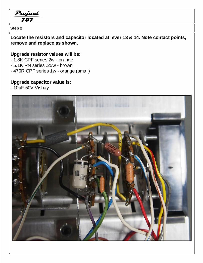
Locate the resistors and capacitor located at lever 13 & 14. Note contact points,
remove and replace as shown.
Upgrade resistor values will be:
- 1.8K CPF series 2w - orange
- 5.1K RN series .25w - brown
- 470R CPF series 1w - orange (small)
Upgrade capacitor value is:
- 10uF 50V Vishay
Step 3
Project747
Project747
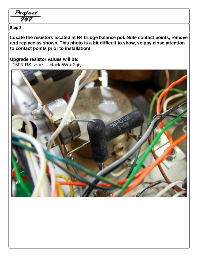
Locate the resistors located at R4 bridge balance pot. Note contact points, remove
and replace as shown. This photo is a bit difficult to show, so pay close attention
to contact points prior to installation!
Upgrade resistor values will be:
- 150R RS series – black 5W x 2qty
Step 4
Project747
Project747
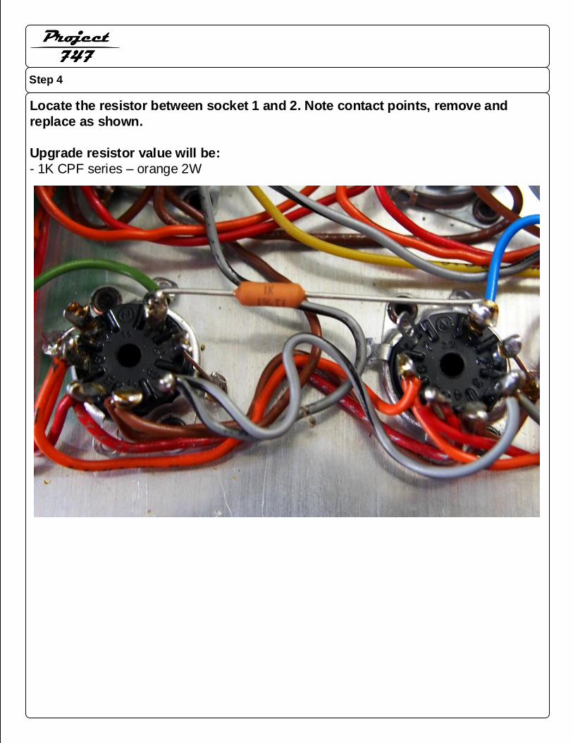
Locate the resistor between socket 1 and 2. Note contact points, remove and
replace as shown.
Upgrade resistor value will be:
- 1K CPF series – orange 2W
Step 5
Project747
Project747
1. Take extremely detailed photos of your original PCB and wiring BEFORE teardown. This will come in handy if you
get lost in the process!
2. Using a 3/8th nut driver, remove the two nuts securing the stock PCB to the meter
3. Using cutters, snip each wire lead free from the circuit board. ALWAYS leave 2-3mm of wire jacket exposed / still
attached to the PCB for color reference in case you get lost
4. Cut both wire leads connected to the eyelets & 220uF capacitor. These eyelets are the ones under the 3/8th nuts
you previously remove from the meter / PCB
5. Once the PCB is free, lift the PCB off of the meter and set aside
6. There is a terminal strip under the PCB, above the meter. This terminal strip will contain several components
including an LED or bulb power light and the shorts neon lamp. Cut the orange, yellow and white wire from this
terminal strip. Keep these three wires separate from the rest of the wire bundle. Unbolt this terminal strip and set
aside. It will not be reused.
7. Strip every wire cut from the PCB & terminal strip at approximately 3/16th”
(except large 120V wire coming from the
wall outlet). Once stripped, solder a gold female pin to each wire lead. Also, solder gold female pins onto the neon
shorts bulb and onto the provided LED with wire leads. Observe polarity on the LED when installing. The black wire
lead goes to the negative pin on the PCB
8. Solder the wall outlet wire lead which attaches to the transformer lead to a single female pin to connect to the new
PCB (shown later in photo examples)
9. Take the two #55 bulbs out of the bayonet sockets of your original PCB. Use your soldering iron and solder sucker
to remove the two bayonet sockets, R10 trimmer, R17 trimmer and R20 trimmer. These components will be re -used
unless you ordered a kit that has new versions of these parts. They are not included by default as in most all cases,
they are still perfectly good
10. Solder in the bayonet sockets and trimmers to the proper locations on the new PCB
11. Test your meters movement. The meter should read very close to 100Ω across the studs. Most will vary from 95-
100Ω, this is perfectly normal. Anymore than 5%, you should attach a series resistor equal to the percentage variance.
An example would be, if your meter reads 92Ω , add in an 8Ω resistor
12. You are now ready to install your new PCB assembly. Make sure all washers have been removed from the meter.
The PCB should sit directly on the two nuts holding the meter assembly together. Place the two lock washers on the
top side of the PCB / over the meter studs. Then tighten the 3/8th nuts over the lock washers. DO NOT
OVERTIGHTEN. Simply secure the PCB
13. Starting at the back of the PCB, attach the 3 terminal strip leads to the proper spots at the back edge of the PCB
as the terminal strip components were included on the PCB to make installation cleaner and easier
14. Attach all other wire leads to their proper locations on the PCB. All wire colors are shown on the PCB as well as
stock wire designators. The next several pages show photos of the connections.
***** CRITICAL NOTES: Very early revisions of the 747 have reversed wire colors on many of the
transformer leads. An example: Newer 747's may have an orange wire with blue stripe. On very
early revisions, the wire may be blue with an orange stripe. The wire will still be placed on the
PCB at the designator ORN/BLU *****
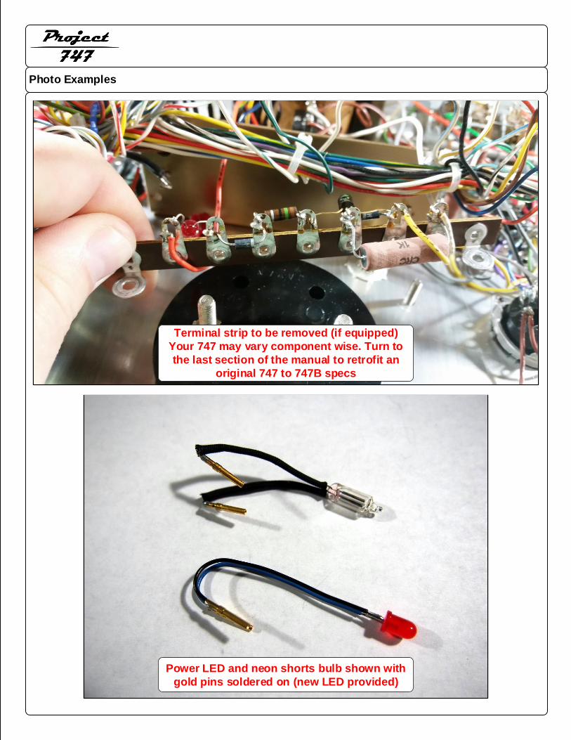
Photo Examples
Project747
Project747
Power LED and neon shorts bulb shown with
gold pins soldered on (new LED provided)
Terminal strip to be removed (if equipped)
Your 747 may vary component wise. Turn to
the last section of the manual to retrofit an
original 747 to 747B specs
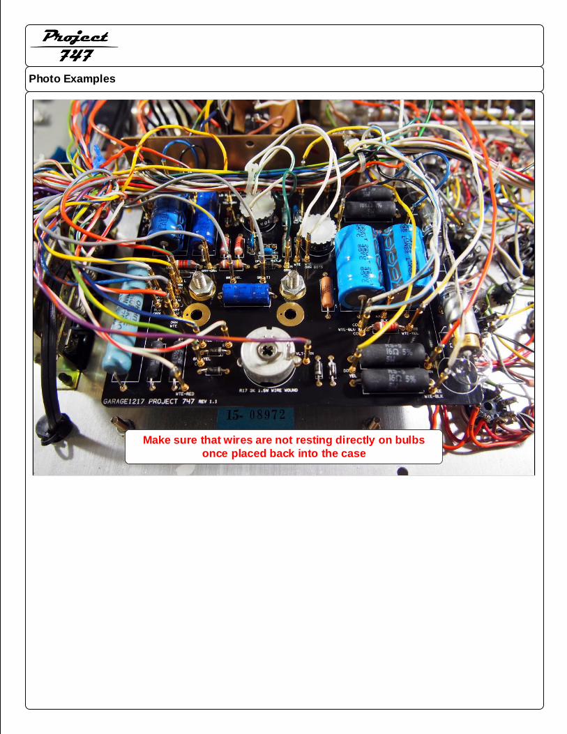
Photo Examples
Project747
Project747
Make sure that wires are not resting directly on bulbs
once placed back into the case
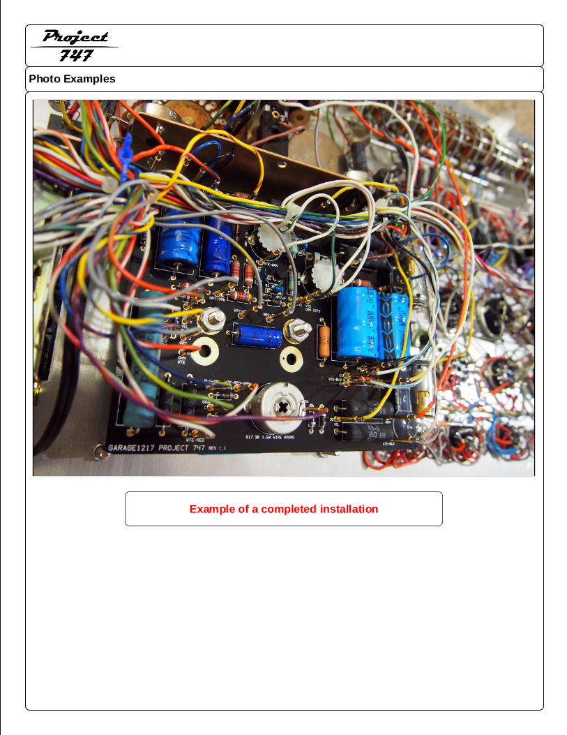
Photo Examples
Project747
Project747
Example of a completed installation
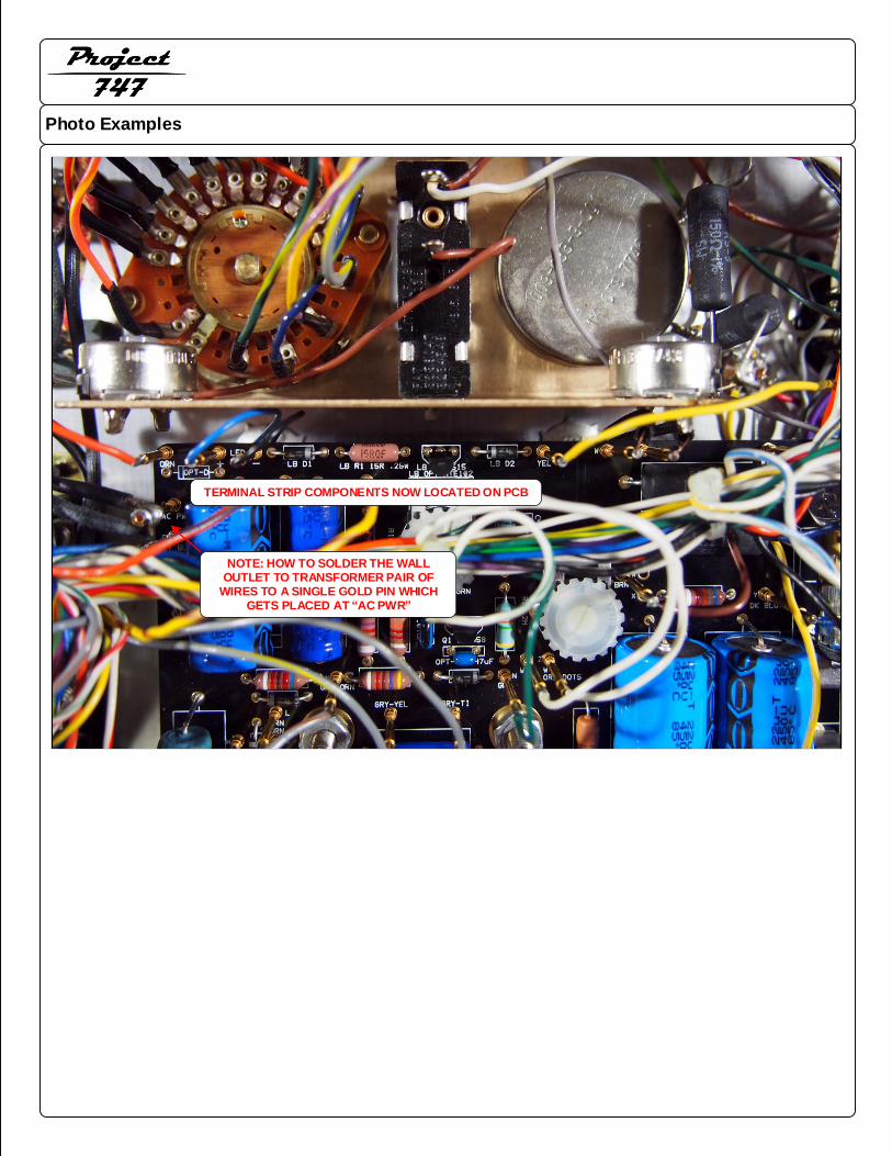
Photo Examples
Project747
Project747
TERMINAL STRIP COMPONENTS NOW LOCATED ON PCB
NOTE: HOW TO SOLDER THE WALL OUTLET TO TRANSFORMER PAIR OF
WIRES TO A SINGLE GOLD PIN WHICH GETS PLACED AT “AC PWR”
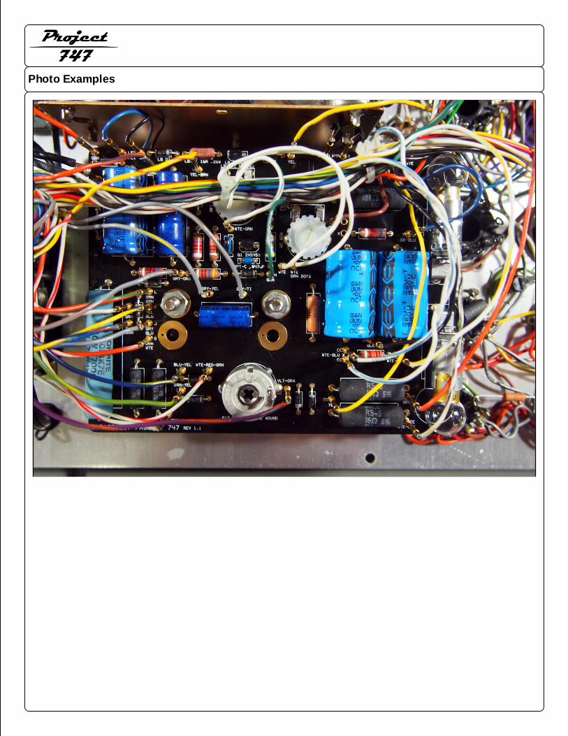
Photo Examples
Project747
Project747
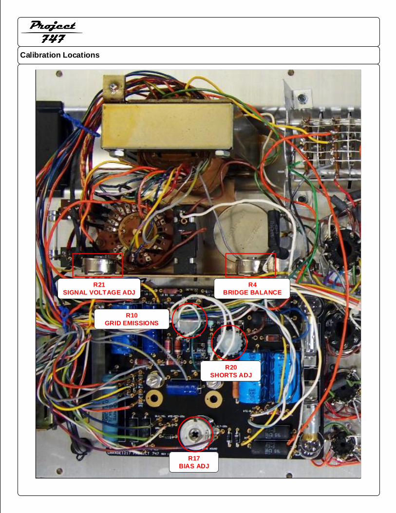
Calibration Locations
Project747
Project747
R17
BIAS ADJ
R20
SHORTS ADJ
R10
GRID EMISSIONS
R4
BRIDGE BALANCE
R21
SIGNAL VOLTAGE ADJ
Calibration Procedures
Project747
Project747
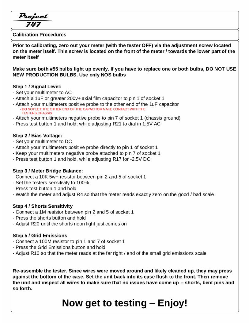
Prior to calibrating, zero out your meter (with the tester OFF) via the adjustment screw located
on the meter itself. This screw is located on the front of the meter / towards the lower part of the
meter itself
Make sure both #55 bulbs light up evenly. If you have to replace one or both bulbs, DO NOT USE
NEW PRODUCTION BULBS. Use only NOS bulbs
Step 1 / Signal Level:
- Set your multimeter to AC
- Attach a 1uF or greater 200v+ axial film capacitor to pin 1 of socket 1
- Attach your multimeters positive probe to the other end of the 1uF capacitor - DO NOT LET THE OTHER END OF THE CAPACITOR MAKE CONTACT WITH THE TESTERS CHASSIS
- Attach your multimeters negative probe to pin 7 of socket 1 (chassis ground)
- Press test button 1 and hold, while adjusting R21 to dial in 1.5V AC
Step 2 / Bias Voltage:
- Set your multimeter to DC
- Attach your multimeters positive probe directly to pin 1 of socket 1
- Keep your multimeters negative probe attached to pin 7 of socket 1
- Press test button 1 and hold, while adjusting R17 for -2.5V DC
Step 3 / Meter Bridge Balance:
- Connect a 10K 5w+ resistor between pin 2 and 5 of socket 1
- Set the testers sensitivity to 100%
- Press test button 1 and hold
- Watch the meter and adjust R4 so that the meter reads exactly zero on the good / bad scale
Step 4 / Shorts Sensitivity
- Connect a 1M resistor between pin 2 and 5 of socket 1
- Press the shorts button and hold
- Adjust R20 until the shorts neon light just comes on
Step 5 / Grid Emissions
- Connect a 100M resistor to pin 1 and 7 of socket 1
- Press the Grid Emissions button and hold
- Adjust R10 so that the meter reads at the far right / end of the small grid emissions scale
Re-assemble the tester. Since wires were moved around and likely cleaned up, they may press
against the bottom of the case. Set the unit back into its case flush to the front. Then remove
the unit and inspect all wires to make sure that no issues have come up – shorts, bent pins and
so forth.
Now get to testing – Enjoy!
CONVERSION FROM 747 TO 747B
Project747
In this portion of the manual, we discuss how to add in a circuit breaker and LED
power light / associated electronics per the last version of the 747B
CIRCUIT BREAKER INSTALLATION
Project747
Project747
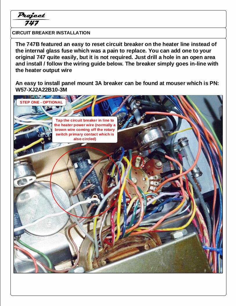
The 747B featured an easy to reset circuit breaker on the heater line instead of
the internal glass fuse which was a pain to replace. You can add one to your
original 747 quite easily, but it is not required. Just drill a hole in an open area
and install / follow the wiring guide below. The breaker simply goes in-line with
the heater output wire
An easy to install panel mount 3A breaker can be found at mouser which is PN:
W57-XJ2A22B10-3M
Tap the circuit breaker in line to
the heater power wire (normally a
brown wire coming off the rotary
switch primary contact which is
also circled)
STEP ONE - OPTIONAL
747 TO 747B WITH LED POWER INDICATOR
Project747
Project747
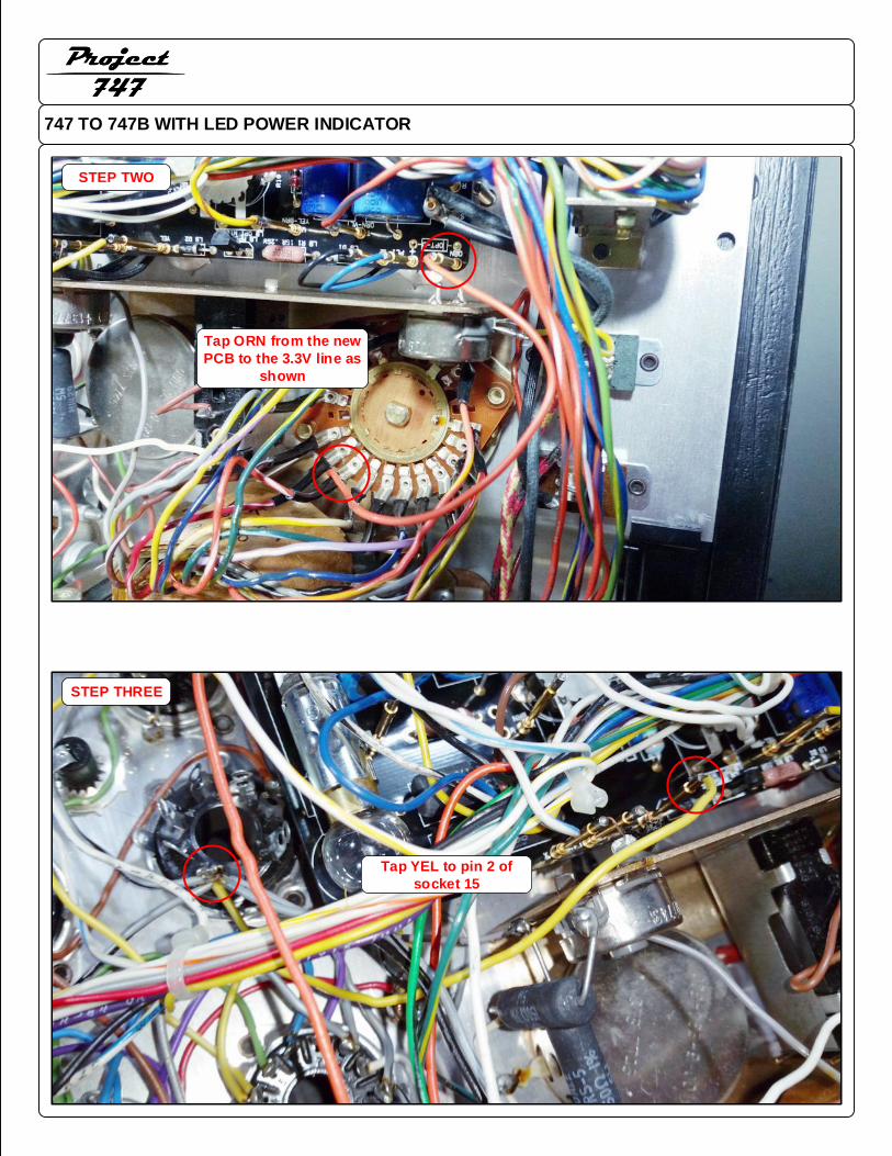
STEP THREE
Tap YEL to pin 2 of
socket 15
Tap ORN from the new
PCB to the 3.3V line as
shown
STEP TWO
747 TO 747B WITH LED POWER INDICATOR
Project747
Project747
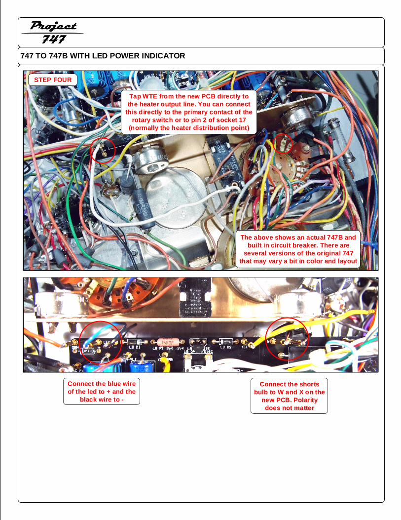
Tap WTE from the new PCB directly to
the heater output line. You can connect
this directly to the primary contact of the
rotary switch or to pin 2 of socket 17
(normally the heater distribution point)
STEP FOUR
The above shows an actual 747B and
built in circuit breaker. There are
several versions of the original 747
that may vary a bit in color and layout
Connect the blue wire
of the led to + and the
black wire to -
Connect the shorts
bulb to W and X on the
new PCB. Polarity
does not matter