project #1, part 1: breadboarding the circuit - tone fiend · diy club 1 project 1, part 1 ... diy...
TRANSCRIPT

©2011 by Joe Gore
tonefiendDIY CLUB
1
Project 1, Part 1Breadboarding a Bad-Ass Distortion Circuit
v03, 03.16.12
©2011 by Joe Gore
tonefiendDIY CLUB
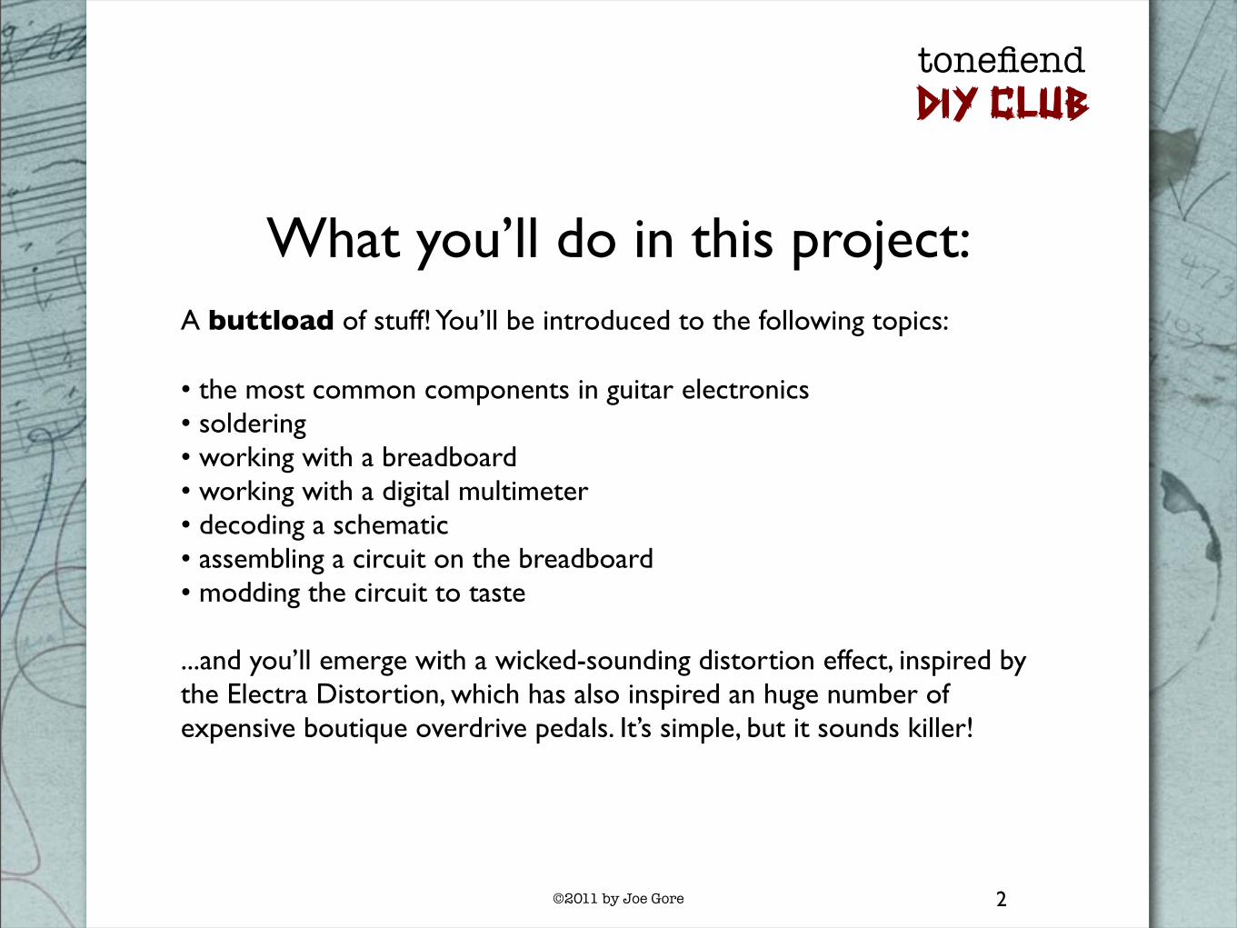
What you’ll do in this project:A buttload of stuff! You’ll be introduced to the following topics:
• the most common components in guitar electronics• soldering• working with a breadboard• working with a digital multimeter• decoding a schematic• assembling a circuit on the breadboard• modding the circuit to taste
...and you’ll emerge with a wicked-sounding distortion effect, inspired by the Electra Distortion, which has also inspired an huge number of expensive boutique overdrive pedals. It’s simple, but it sounds killer!
2

©2011 by Joe Gore
tonefiendDIY CLUB
What you need for this project:Tools and supplies:
1. Soldering iron (preferably 30 watts or more, but not a gun-type iron) 2. Lead-free solder 3. A damp sponge 4. A small electronics breadboard 5. Hookup wire, preferably 24-gauge, stranded and pre-bonded, in several colors, including black, red, and white 6. An assortment of jumper cables (you could make your own from the above wire, but the prefab kind have metal tips that don’t fray from repeated use) 7. Wire stripper 8. Wire cutter (most strippers have cutters, but you’ll probably want a separate flush-edged tool for tight, close cuts) 9. Needle-nose pliers 10. A “helping hand” vise 11. An electric guitar, an amp, and two audio cables 12. A digital multimeter with a continuity function. “Auto-ranging” is another plus.
Electronic components:
1. Four resistors. Values: 470R, 10K, 68K, 2.2M.2. Four capacitors. Values: 473 (sometimes called .047uF or 47n) 683 (AKA .068uF or 68n) and two 104 (.1uF or 100n)3. Three transistors. Values: 2N5088, 2N5089, and 2N3904.4. Two diodes. A1N4001 and a 1N914 will sound great, but you may enjoy experimenting with others.5. Two potentiometers (“pots”). Values: A100K and C10K. (You can substitute a B10K if you can’t find a C10K.)6. 9-volt battery.7. Battery snap (connector).
Not all components will be used in the final project. The extras are for auditioning purposes, so you build according to your needs and taste.
3
©2011 by Joe Gore
tonefiendDIY CLUB
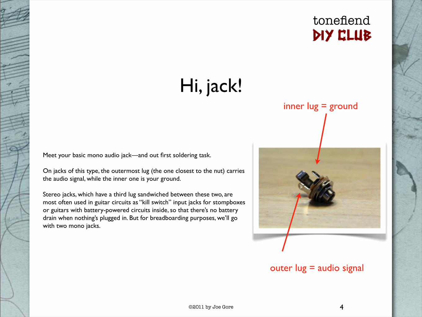
Hi, jack!
Meet your basic mono audio jack—and out first soldering task.
On jacks of this type, the outermost lug (the one closest to the nut) carries the audio signal, while the inner one is your ground.
Stereo jacks, which have a third lug sandwiched between these two, are most often used in guitar circuits as “kill switch” input jacks for stompboxes or guitars with battery-powered circuits inside, so that there’s no battery drain when nothing’s plugged in. But for breadboarding purposes, we’ll go with two mono jacks.
4
inner lug = ground
outer lug = audio signal

©2011 by Joe Gore
tonefiendDIY CLUB
It’s soldering time!
5
I’ve referenced several “intro to soldering” tutorials at www.tonefiend.com, and I recommend studying them before proceeding. These include info about choosing the right iron, and safety precautions (i.e., don’t touch the hot iron, use lead-free solder, work in a ventilated area, and wash you hands after working with this stuff).
Here’s a recap of the basics:
1. Let you iron heat up for a few minutes. 2. Keep a damp sponge handy, and swab the tip of your iron often to keep it clean. 3. “Tin” the tip by touching a bit of solder to it before starting. 4. When you work, don’t melt solder by touching it to the iron. Instead, apply the iron to the surfaces you want to bond, and then touch the solder to the hot surfaces. 5. You may want to use a “helping hands” vise to hold your work. 6. Eye protection recommended! 7. Opt for lead-free solder. Here I exposed about 1/4-inch of bare wire using the wire stripper. I threaded it through the lug, and then pinned it in place with the tip of the iron. Finally, I touched the solder to lug, next to, but not quite touching, the iron’s tip. When the solder melts, remove the iron, and then let the solder set (it only takes a couple of seconds).
As a visual aid, you may want to use black wire for the ground lug, and white for the audio lug.

©2011 by Joe Gore
tonefiendDIY CLUB
Solder both jacks
1. Attach the two wires to both your mono jacks. Snip off any extra wire.
2. Use about eight inches of wire so you have ample working room.
3. Strip about 1/4 inch from the unconnected end of all four wires.
6
Inspect your connections. Good solder jointslook smooth and shiny!

©2011 by Joe Gore
tonefiendDIY CLUB
Meet the BreadboardIt’s often a good idea to assemble circuits on a breadboard before attempting to solder them to a circuit board. That way, you can audition sounds before committing to them, and experiment with various options.
Your breadboard may not look exactly like this, but the following comments probably apply.
The outermost lines of holes are connected lengthwise across the diameter of the breadboard. They’re usually color-coded red and black, with red used for battery power and black used for ground. Any component plugged into one of these “busses” will be connected to any others plugged in to the same parallel line.
The breadboard pictured here has four busses. Some have more. Only two are needed for our purposes. Also, some breadboards split the long horizontal busses into two separate regions. If your breadboard has a physical gap midway along the bus, you may need to insert a jumper cable between the two regions to connect them.
7

©2011 by Joe Gore
tonefiendDIY CLUB
Meet the BreadboardThe large area between the power and ground busses consists of many smaller, shorter busses. There are oriented perpendicular to the longer busses.
All the components get laid out in this center area. Some of these will also connect to the longer power and ground busses.
If you run out of holes on one of these short busses, you can use jumper cables to connect multiple columns.
8

©2011 by Joe Gore
tonefiendDIY CLUB
Meet the Multimeter
9
They call it a MULTImeter because it has several functions. First, we’ll check the voltage of our 9V battery by setting the meter to its DC power function (it’ll probably say “DCV”). Touch the red tip to the battery’s positive (male) terminal and the black to the negative (female) terminal. If the battery is fresh, it’ll probably read close to 9.5 volts.

©2011 by Joe Gore
tonefiendDIY CLUB
Connect the Battery
Attach your battery snap, and connect the read wire to one of the red busses, and the black to one of the black. (The colors are just a visual aid—these busses are electronically identical.)
I could have connected the black wire to the black bus right next to the red one, but I used the one at the opposite side of the breadboard. This is because electronic schematics traditionally show power connections at toward the top of the diagram and ground connections toward the bottom. Mirroring that arrangement can make it easier to transpose a circuit from a schematic to a breadboard, as we’ll be doing shortly.
10

©2011 by Joe Gore
tonefiendDIY CLUB
Let’s Add Audio
Now let’s connect the audio wires. Plug the two ground connections into the ground bus alongside the negative battery wire. Plug one of the white wires into the upper left-most column, and the other into the lower left-most column. They are not yet connected.
Plug in both your audio cables. Plug your guitar into the jack connected to the upper-left bus. Plug your amp into the jack connected to the lower bus.
It’s a good idea to tape stray cables to your work surface. This is going to get messy.
11

©2011 by Joe Gore
tonefiendDIY CLUB
Connect the Input and OutputTo hear the guitar through this circuit, you must connect the input and output. Connect one end of a short jumper cable to the input bus, and one to the output bus. (If you don’t have prefab jumper cables, you can make you own by stripping the ends from a short piece of wire. But the prefab ones have metal pins, so they can be used over and over without fraying the ends. Trust me, you’ll appreciate this soon, if you don’t already.)
Turn on your amp. Do you hear your normal sound? Congrats! You’ve done a bunch of work, and accomplished nothing! (Yet.)
Don’t hear anything? Verify that your solder connections are solid. Check that the battery snap is firmly in place. Triple-check that all wires are in the correct holes. Make sure your audio cables are good. (FYI, the battery isn’t doing anything yet. You could disconnect it at this point and still hear your guitar.)
And use your new troubleshooting tool: the multimeter!
12

©2011 by Joe Gore
tonefiendDIY CLUB
Troubleshooting with the MultimeterSet your multimeter to its “continuity” function. This is simply a beeper that sound whenever you touch the test leads to two properly connected point in a circuit.
If you hear your guitar now as you should, try touching the leads to the “hot” lugs of the two jacks (the ones with white wire).
If you hear guitar and a beep, you’re awesome.
If you hear guitar but no beep, you haven’t set your meter properly.
If you hear a beep but no guitar, you have a bad cable, your amp isn’t on, or your guitar’s volume is turned down.
If you hear no guitar and no beep, remove the wires and components from the breadboard and use the continuity function to test the individual pieces. For example, touch one lead to a jack lug, and the other to the end of the wire connected to it.
13
Get used to this view.You’ll see it often.
©2011 by Joe Gore
tonefiendDIY CLUB
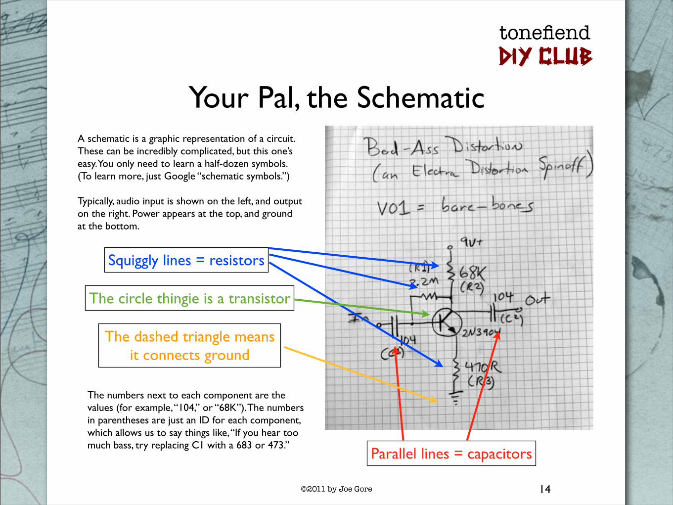
Your Pal, the SchematicA schematic is a graphic representation of a circuit. These can be incredibly complicated, but this one’s easy. You only need to learn a half-dozen symbols. (To learn more, just Google “schematic symbols.”)
Typically, audio input is shown on the left, and output on the right. Power appears at the top, and ground at the bottom.
14
Parallel lines = capacitors
Squiggly lines = resistors
The circle thingie is a transistor
The dashed triangle means it connects ground
The numbers next to each component are the values (for example, “104,” or “68K”). The numbers in parentheses are just an ID for each component, which allows us to say things like, “If you hear too much bass, try replacing C1 with a 683 or 473.”

©2011 by Joe Gore
tonefiendDIY CLUB
What Does What?
15
1
35
2
4
6
1. Your guitar signal enters here. C1 acts as a filter. A smaller capacitor removes more lows.
2. The transistor amplifies your guitar signal—so much so that it distorts. Different transistors provide different amounts of gain. The guitar signal enters at the base (the middle pin, in our case), and emerges from the collector.
3. The battery powers the transistor via its collector. R2 regulates the amount of current reaching the transistor.
4. R3 regulates the amount of current flowing from the transistor’s emitter to ground. Lower values equal more gain.
5. R1 adds some current from the battery to the pre-transistor input signal.
6. C2 converts the DC signal to AC before it hits your guitar amp (or other stompboxes).
Note: To get you up and running with minimum theorizing, these explanations are very simplified. Check out the recommended reading at the end of this article for more info.

©2011 by Joe Gore
tonefiendDIY CLUB
Here Comes Trouble: The Transistor!Here’s where the godawful noise magic happens.
In these first few projects, the transistor will work as an amplifier. In this project, it will amplify so much that it will distort. A lot.
We’re going to audition three transistors in this circuit: a 2N3904, a 2N5088, and a 2N5089. All three are of a type known as the silicon BJT (bi-junction transistor). This is just one of many types.
While our initial projects all use a single transistor, some circuits use many of them. In fact, the number of transistors is one of the defining properties of many boost/overdrive/distortion/fuzz circuits. (Fuzz Faces use two, Tone Benders usually use three, and Big Muffs have four).
More isn’t better—just different. Many great circuits use just one transistor. Examples include the mighty Dallas-ArbiterRangemaster, the crispy-clean Z. Vex Super Hard On, and the popular Electra distortion circuit, from which this project is derived.
16

©2011 by Joe Gore
tonefiendDIY CLUB
The ABCs of CBETransistors of this type have three terminals: the collector, base, and emitter, often abbreviated as C, B, and E.
The collector “collects” juice from the red power bus. Your guitar signal goes to the base. And the emitter connects to the ground bus. But in most cases, there are one or more components between the C, B, and E pins and those destinations.
Confused? Sadly, it gets worse.
The location of the C, B, and E pins can vary from one transistor type to another, even ones that look identical! This pattern is called the “pinout.” Varying pinouts are among the biggest pains in DIY electronics.
Thankfully, the three transistors used in this project share the same pinout. With the plastic part toward you, and its rounded side facing left, the pinout it C, B, E, from top to bottom.
Hint: It’s easy to check a pinout online. For example, just Google “2N5088 pinout,” and you’ll find your way to a manufacturer’s spec sheet with all the necessary info.
17
C
B
E
The above pinout applies to the three BJTs used in this project—but sadly, not all transistors.

©2011 by Joe Gore
tonefiendDIY CLUB
Place the Transistor
Even though the transistor’s terminals are shown top-to-bottom in the schematic, we must place it sideways—otherwise, the three connection would all be linked on the same bus.
The exact position on the breadboard doesn’t matter. Anything like this will work.
As positioned here, with the curved side facing up, the collector (C) is to the right, and the emitter (E) is to the left.
Use the 2N3904 transistor to start. Later we’ll audition the others.
18

©2011 by Joe Gore
tonefiendDIY CLUB
Working with Resistors
Resistors are not polarized, which means it doesn’t matter which way you insert them.
There are three ways to measure the value of resistors:
1. Read the bag it came in. This is my favorite technique.
2. Memorize the resistor color codes. This is my least favorite technique.
3. Use the multimeter’s ohmmeter function. This is usually indicated by an omega symbol (Ω). Just touch the test leads to the two terminals. (If your multimeter doesn’t have auto-ranging, you may have to manually adjust the range to get a reading.)
To test resistors, you must remove them from the circuit, as shown here. The values can vary by as much as 10%, so don’t sweat it if, say, your 10K resistor reads as 9.77K.
19
©2011 by Joe Gore
tonefiendDIY CLUB
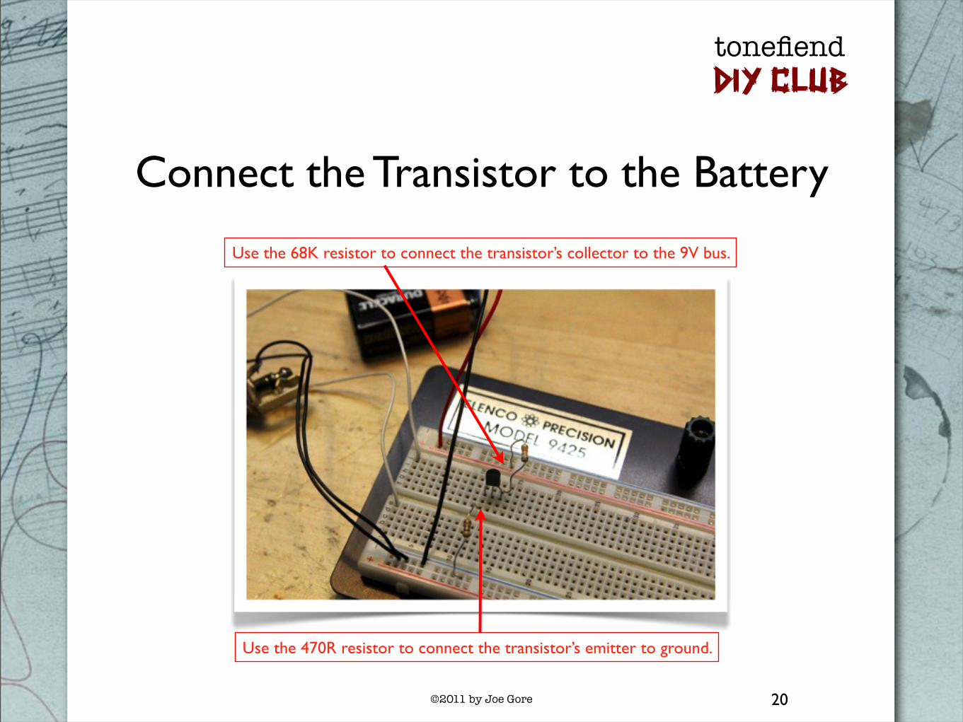
Connect the Transistor to the Battery
20
Use the 68K resistor to connect the transistor’s collector to the 9V bus.
Use the 470R resistor to connect the transistor’s emitter to ground.

©2011 by Joe Gore
tonefiendDIY CLUB
Place a Resistor Between the Transistor’s Collector and Base
21
Place the 2.2M resistor between the transistor’s collector and base. (You will now have two resistors connected to the collector.)

©2011 by Joe Gore
tonefiendDIY CLUB
Working with Capacitors
In some cases, the orientation of the capacitor (or “cap”) matters, but not with the caps we’re using here.
The value of the cap is important, but the cap type usually isn’t. Mylar, ceramic, and box-type caps all work equally well here.
Cap values are printed on the component. But sadly, there are three different ways of denoting cap values.
Here are the three ways of referring to the cap values used in this project:
104 = .1uF = 100n 683 = .068uF = 68n 473 = .047uF = 47n
Google “capacitor values” for more info.
22
Three 104 capacitors types: mylar film, ceramic, and box (also mylar, but in a slicker package). They’ll sound identical in this circuit.
©2011 by Joe Gore
tonefiendDIY CLUB
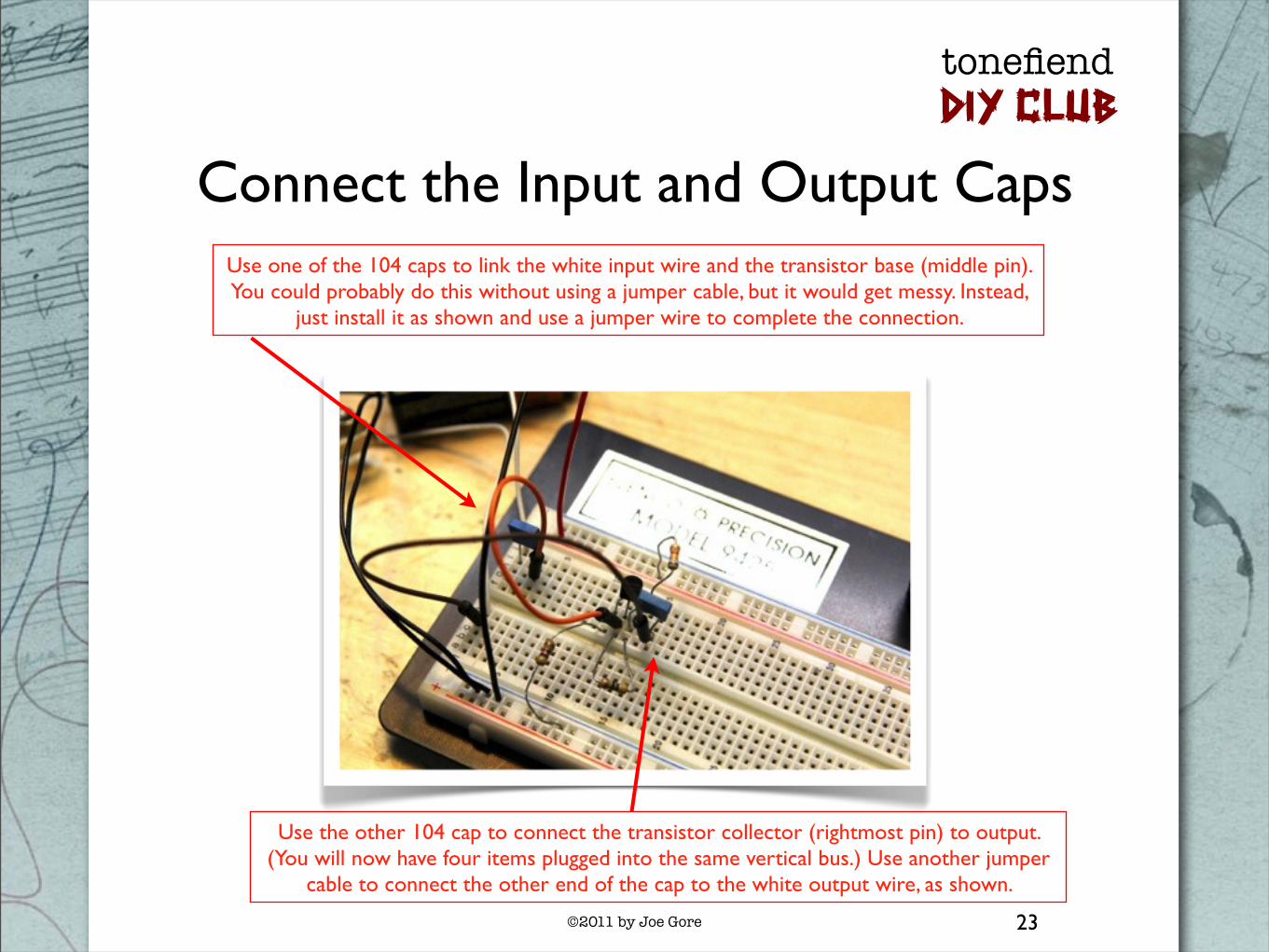
Connect the Input and Output Caps
23
Use one of the 104 caps to link the white input wire and the transistor base (middle pin). You could probably do this without using a jumper cable, but it would get messy. Instead,
just install it as shown and use a jumper wire to complete the connection.
Use the other 104 cap to connect the transistor collector (rightmost pin) to output. (You will now have four items plugged into the same vertical bus.) Use another jumper
cable to connect the other end of the cap to the white output wire, as shown.

©2011 by Joe Gore
tonefiendDIY CLUB
Hope you had your amp turned down!
You should now hear insanely loud guitar distortion.
This is the circuit at maximum loudness. We’ll be shaping and controlling it in Part 2 of this project.
If you get anything other than heavy-duty distortion, quadruple-check all connections (especially those confusing transistor pins). Compare your work to the v01 schematic, and use the multimeter’s continuity function to verify adjacent connections.
BTW, it’s extremely rare for any of these components to fail. If the circuit doesn’t work as expected, you can pretty much bet that the cause is human error. (One exception: Cheap jumper cables can be funky. Try swapping these out if necessary.)
Coming next in Part 2: Shaping and Modding the Circuit!

©2011 by Joe Gore
tonefiendDIY CLUB
Appendix: Recommended Reading
25
Here are three fine “electronics for beginners”books:
Getting Started in Electronics by Forrest M. Mimms III
Electronics for Dummies by Cathleen Shamieh and Gordon McComb
Make:Electronics Book by Charles Platt
But to be honest,most of you self-education is likely to take place online. I particularly recommend three stompbox-building sites as great places for beginners to learn.
diystombboxes is probably the largest online builders community. Their forum is a great place to ask questions,and the FAQ section of the diystompboxes wiki is so helpful you may want to print out a hard copy,if not tattoo it on your forearms.
My favorite DIY writer is Dano from Beavis Audio Research. Sadly,his site is dormant,but his many fine articles are still posted there. He’s funny and pragmatic,with a knack for zeroing in on the crucial info. I recommend everything in his Tech Section,especially this,this,this,this,this,this,this,this,and this. And be sure to archive copies,in case this resource ever vanishes.
Gaussmarkov DIY Effects is more sober than the fun-loving Beavis site. But in addition to hosting many fabulous stompbox projects,Gaussmarkov boasts a fine tech section with articles dedicated to all the key components.