progress on engine les using star-cd - siemens · progress on engine les using star-cd ... •...
TRANSCRIPT

www.cd-adapco.com
Progress on Engine LES Using STAR-CD
A D Gosman
CD-adapco
Japan STAR Conference 2012, Yokohama

1. Nature and motivation for LES of engines
2. LES modelling in STAR-CD
3. Collaborations
4. Validation studies
5. Applications
INTRODUCTION

MOTIVATION FOR ENGINE LES
ADVANTAGES OF LES OF ENGINES
• because only small scales modelled, is inherently more accurate.
• calculate individual cycles, so obtain information on cycle-to-cycle variations
➝ principal motivation
• small-scale modelling easier than RANS modelling in some, but not all areas.
COMPARISON LES AND RANS
• RANS models all scales of fluctuation
around mean
• LES models only small scales and
directly computes larger ones RAN
S
LE
S
ACTUAL
DRAWBACKS OF LES
• moderately more expensive/cycle, but need many cycles to get statistics
• more effort to set up, e.g. more detailed boundary conditions required
• puts more demands on numerical solver – both accuracy and speed.

CD-adapco ACTIVITIES IN ENGINE LES
UNIVERSITY COLLABORATION AND SPONSORSHIP
• Penn State Univ.: Professor D Haworth
• Cornel Univ: Prof S Pope
• Darmstadt Univ: Prof J Janicka
• Modena Univ: Prof S Fontanesi
• Imperial College London: Prof W P Jones
IN-HOUSE DEVELOPMENT OF LES CAPABILITIES
• several experts in LES modelling and numerics
• current focus on combustion
ENGINEERING SERVICES PROJECTS
COLLABORATIVE PROJECTS WITH INDUSTRIAL PARTNERS
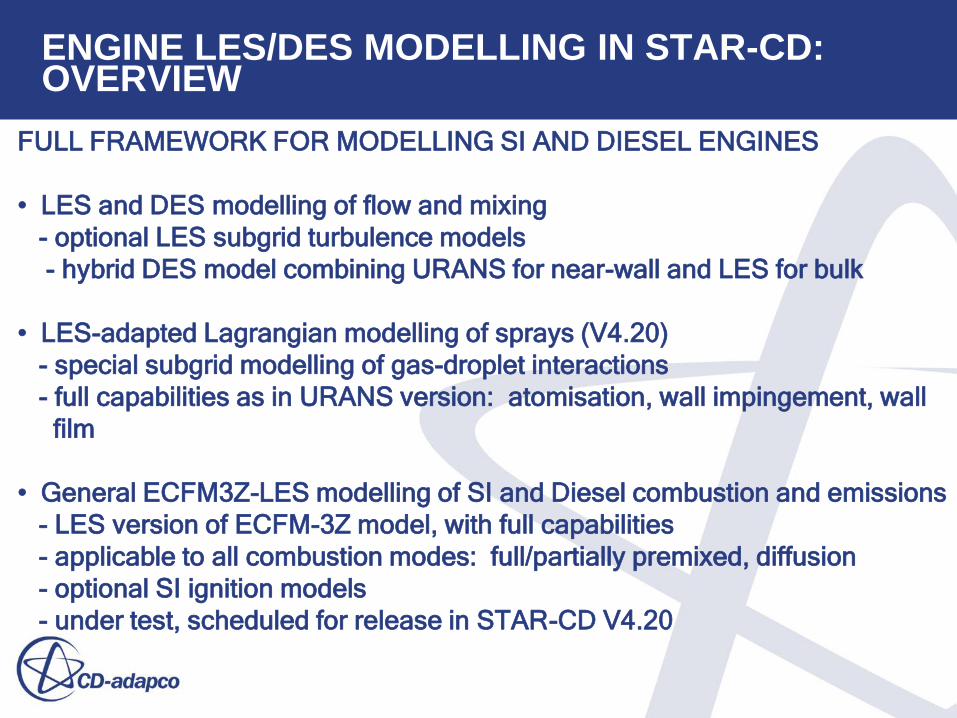
ENGINE LES/DES MODELLING IN STAR-CD: OVERVIEW
FULL FRAMEWORK FOR MODELLING SI AND DIESEL ENGINES
• LES and DES modelling of flow and mixing
- optional LES subgrid turbulence models
- hybrid DES model combining URANS for near-wall and LES for bulk
• LES-adapted Lagrangian modelling of sprays (V4.20)
- special subgrid modelling of gas-droplet interactions
- full capabilities as in URANS version: atomisation, wall impingement, wall
film
• General ECFM3Z-LES modelling of SI and Diesel combustion and emissions
- LES version of ECFM-3Z model, with full capabilities
- applicable to all combustion modes: full/partially premixed, diffusion
- optional SI ignition models
- under test, scheduled for release in STAR-CD V4.20

LES SUBGRID MODELLING OPTIONS
Filtered LES equations, subgrid viscosity modelling
Options
1. Smagorinsky
Sij =1
2
¶ui
¶x j
+¶u j
¶x i
æ
è ç ç
ö
ø ÷ ÷
2. One-equation subgrid k model
• transport equation solved for ksgs

DES MODELLING – I INTRODUCTION
• Hybrid non-zonal model:
- tends to LES in resolved flow
- tends to URANS in unresolved
• Automatic selection of length scale
according to grid:turbulence length scale
ratio
• Preferable to limit URANS to near-wall
region
• Several variants based on different URANS models
- Spalart-Almaras
- k-ω SST
- k-ε

DES MODELLING II - EXAMPLE
SPALART-ALMARAS DES MODEL
• one-equation model: both high-Re and low-Re versions
• tends to Smagorinsky-type LES model when CDESΔ/d > 1
d = wall normal distance, Ψ ≈ 1 at high Re
n =n t
fn1
®n t at high Re
• dissipation rate depends on controlling turbulent length scale
˜ d

ECFM3Z-LES COMBUSTION MODELLING – I OUTLINE
Full ECFM-3Z adapted for LES
• coherent flame model for premixed burning
• eddy dissipation model for diffusion burning
• 3-zone modelling for sub-grid mixing
• equilibrium modelling for burnt gas
• Zeldovich NOx chemistry
• range of soot models
• range of knock models
Two optional spark ignition models
1. Eulerian AKTIM
2. AKTIM adapted for LES

ECFM3Z-LES COMBUSTION MODELLING – II LES FLAME SURFACE DENSITY EQUATION
Transport equation for flame surface density
• Tres = resolved transport
• Tsgs = subgrid transport
• P = laminar propagation
• Sres = resolved strain
• Ssgs = subgrid strain
• Cres = resolved curvature
• Csgs = subgrid curvature

KEY NUMERICAL ALGORITHM FEATURES
• Implicit PISO with quasi 2nd order time differencing
• Second-order centered or MARS spatial differencing
for momentum
• MARS for species and other scalars
• Synthetic turbulence inlet conditions
• Non-reflecting inlet/outlet conditions

QUALITY ASSESSMENT CRITERIA FOR LES
1. A-priori ratio integral scale/mesh size = lint /Δ
lint = Cm
0.75k3 / 2 /e• use RANS estimate
• want ratio < 0.5
• accuracy depends on RANS solution
2. Fraction resolved kinetic energy kres/ktot
•
• want ratio > 0.8
kres 1
2u'1
2u'22u'3
2 ; ui
' ˜ u i u i; ktot kres ksgs
3. Ratio LES predicted turbulence scale/mesh size
• obtain length scale from energy spectrum
4. Ratio turbulent: laminar viscosity
• ideally close to unity, minimizes modelling error contribution
5. Other, e.g. Index of Resolution Quality

VALIDATION: MOTORED MODEL ENGINE (PENN STATE U):
Model Engine Configuration Flow during Intake
Axisymmetric, central open valve, flat piston
LES simulations, without/with swirl
• Smagorinsky, wall functions
• 1.3M cell mesh, size ~ 1 mm
• effects of mesh (170K,2.6M), time step (0.1-1.0 CAD), subgrid model (1 eqn)
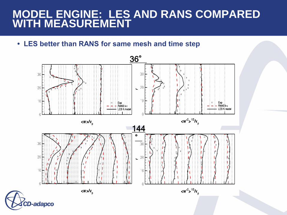
MODEL ENGINE: LES AND RANS COMPARED WITH MEASUREMENT
144°
36°
• LES better than RANS for same mesh and time step
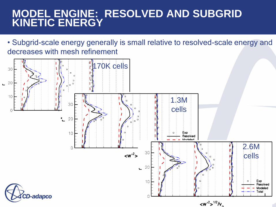
MODEL ENGINE: RESOLVED AND SUBGRID KINETIC ENERGY
• Subgrid-scale energy generally is small relative to resolved-scale energy and
decreases with mesh refinement
170K cells
1.3M
cells
2.6M
cells

MODEL ENGINE: CYCLIC VARIATIONS AND POD ANALYSIS
Cyclic variations investigated using Proper Orthogonal Decomposition (POD)
Similar study underway for the Transparent Combustion Chamber (TCC)
engine

VALIDATION: MOTORED 4-VALVE PENT-ROOF ENGINE (UNIV DARMSTADT)
exhaust intake
exhaust
intake
ENGINE
• 4-valve, pent roof, flat piston
• optical access
• measurements with laser diagnostics
COMPUTATIONAL SET-UP
• Smagorinsky, MARS, Piso
• time-dependent inlet and outlet
pressure boundary conditions
• fixed-temperature inlet
• variable time step, linked to valve motion
• mesh sizes 2.1M (base), 3.2M(refined)
• corresponding mean cell sizes1.2, 0.8mm
• up to 25 successive cycles

phase averaged mean
rms
Intake (270bTDC) Compression (90bTDC)
4-VALVE PENT-ROOF ENGINE: EFFECT OF NUMBER OF CYCLES
Total cycles = 25; phase averages over increasing periods

y (
mm
)
x ( mm
)
y (
mm
)
x ( mm )
base
y (
mm
)
x ( mm )
refined
90°
bTDC
|V| [m/s]
measured
4-VALVE PENT-ROOF ENGINE: FLOW FIELD AT 270O BTDC (INDUCTION)

4-VALVE PENT-ROOF ENGINE: VALIDATION AT 270O BTDC (INDUCTION)
RMS u velocity
y = 0mm
y = -10mm
Phase averaged u velocity

90°
bTDC
|V| [m/s]
4-VALVE PENT-ROOF ENGINE: VELOCITY FIELD AT 90O BTDC (COMPRESSION)
y (
mm
)
x ( mm
)
y (
mm
)
x ( mm )
base
y (
mm
)
x ( mm )
refined
measured

4-VALVE PENT-ROOF ENGINE: VALIDATION AT 90O BTDC (COMPRESSION)
y = 0mm
y = -10mm
Phase averaged u velocity RMS u velocity

90°
bTDC
|V| [m/s]
4-VALVE PENT-ROOF ENGINE: RESOLVED KINETIC ENERGY FRACTION
base refined

4-VALVE PENT-ROOF ENGINE: CONCLUSIONS OF STUDY
1. LES is more accurate than RANS and gives good agreement with
experiment.
2. For reasonable accuracy require:
– Grid size not more than Δ ≈ 1.0 mm to capture 80% - 95% of the TKE (except jets)
– 25 to 50 engine cycles to get accurate statistical means and fluctuations.
3. Cyclic variations most likely to be caused by random nature of turbulence.
4. Accuracy of RANS is not bad, especially for mean velocity.

COMBUSTION IN 4-VALVE HIGH-SPEED GDI TURBOCHARGED ENGINE (U.MODENA)
ENGINE
• 4-valve GDI
• pent-roof, shaped piston
• turbocharged, 10000 rpm
• test-bed measurements
COMPUTATIONAL SET-UP
• STAR-CD development version
• time-varying inlet/outlet pressures
from tuned 1D analysis
• Smagorinsky, wall functions, ECFM-LES,
‘simple’ ignition model
• 1.3M mesh, refined around spark plug
• initialisation from RANS solution
• up to 25 cycles
• research in progress

4-VALVE HIGH-SPEED GDI: CYLINDER PRESSURE PREDICTIONS AND COMPARISON

4-VALVE HIGH-SPEED GDI: CYCLIC VARIATIONS IN FLAME PROPAGATION
27

Interaction between velocity field & flame development
4-VALVE HIGH-SPEED GDI: CYCLIC VARIATIONS IN FLOW AND EQ RATIO
28
Equivalence Ratio

4-VALVE HIGH-SPEED GDI: KNOCK ONSET
PREDICTION FOR HIGH PRESSURE CYCLE
Experimental Spark
Advance
Highly Increased Spark
Advance
Spark Advance - Moderate
Increase
Yellow Isosurface - RVB=0.5
Red Isosurface - Autoigniting
Condition
Experimental Spark
Advance
Spark Advance – High
Increase
Spark Advance - Moderate
Increase
Yellow Isosurface - RVB=0.5
Red Isosurface - Autoigniting
Condition
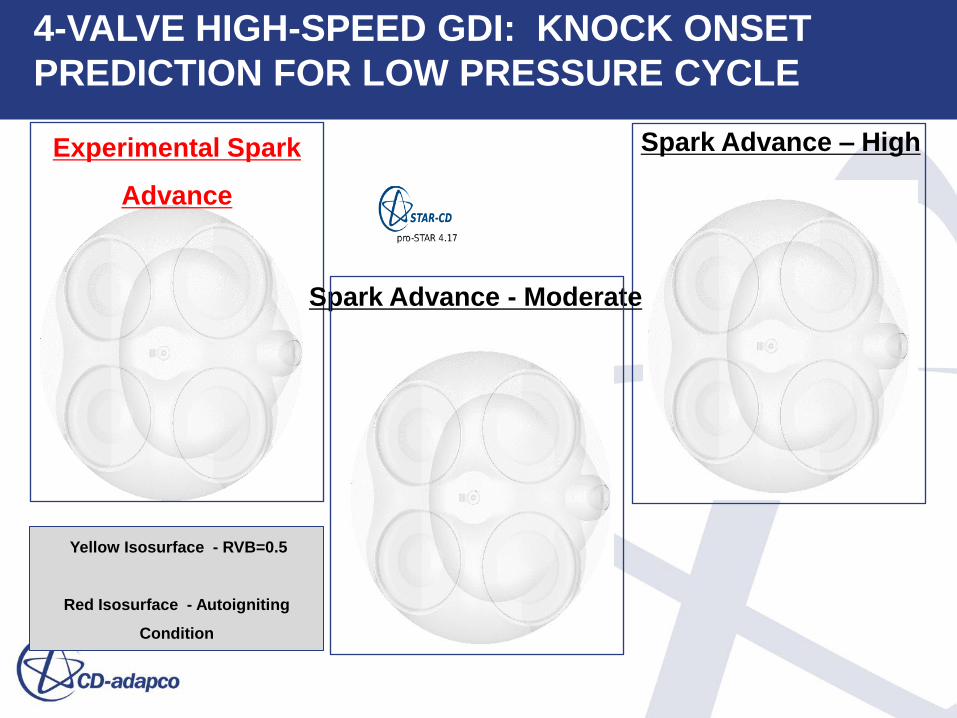
4-VALVE HIGH-SPEED GDI: KNOCK ONSET
PREDICTION FOR LOW PRESSURE CYCLE

SUMMARY
1. Adaptation of STAR-CD for LES and DES of engines is well advanced,
with involvement of internal and external experts and collaborations
with university and industrial partners.
2. Extensive validations have been performed for motored operation, with
satisfactory results.
3. Current development and validation activity for engine combustion is also
producing promising results.
4. The results confirm the clear benefits of LES in improved accuracy and
capability to predict cyclic variability.
5. The experience gained is also helping to identify best practices for LES/DES.

ECFM3Z-LES COMBUSTION MODELLING – III BASIC IGNITION MODEL
Initialise reactedness profile
• evolution of time mean surface area
• wrinkled surface area
• wrinkle factor evolution
• convert Sm into flame surface density???

•ECFM-3Z LES
Ignition (two options in STAR-CD). Basic Model [1,2]
AKTIM [4] with extensions for LES
Basic Model:
Initialise profile for burnt gases volume fraction c as:
with constraint with rk the given initial kernel radius from the RANS model
Model evolution in time of the mean flame surface area Sm(t) with:

•ECFM-3Z LES
Basic Model (continued):
The mean surface Sm will be wrinkled by the turbulence:
with Ξ the wrinkling factor given by the equation:
with S_l, a_t the laminar flame speed and the sgs strain.
Sm is converted into the Flame Surface Density FSD by:

Extensive parametric studies have been performed
Formulation LES or RAS
Computational
mesh 170K, 1.3M, or 2.6M cells
Pressure-correction
algorithm SIMPLE or PISO
LES subfilter-scale
turbulence model
Constant-coefficient Smagorinsky (CS=0.02-1.0) or 1-eqn.
subfilter-scale k model (Ck=0.05-1.5), with wall damping
RAS turbulence
model Standard high-Re k-e w/wall functions
Computational
timestep Dq= 0.1 – 1.0 CAD
Piston motion Fixed number of cells w/deformation or mesh
addition/deletion
Baseline:
LES, 1.3M cells, PISO, 1-eqn. w/Ck=0.3, Dq=0.1 CAD, fixed # of cells
In all cases:
Discard first 2 cycles (min.), average over 3 cycles (min.) + azimuthal
direction