programming spatio-temporal patterns with dna-based circuits
TRANSCRIPT

HAL Id: hal-03190181https://hal.archives-ouvertes.fr/hal-03190181
Submitted on 6 Apr 2021
HAL is a multi-disciplinary open accessarchive for the deposit and dissemination of sci-entific research documents, whether they are pub-lished or not. The documents may come fromteaching and research institutions in France orabroad, or from public or private research centers.
L’archive ouverte pluridisciplinaire HAL, estdestinée au dépôt et à la diffusion de documentsscientifiques de niveau recherche, publiés ou non,émanant des établissements d’enseignement et derecherche français ou étrangers, des laboratoirespublics ou privés.
Programming spatio-temporal patterns with DNA-basedcircuits
Marc van der Hofstadt, Guillaume Gines, Jean-Christophe Galas, AndréEstévez Torres
To cite this version:Marc van der Hofstadt, Guillaume Gines, Jean-Christophe Galas, André Estévez Torres. Programmingspatio-temporal patterns with DNA-based circuits. DNA- and RNA-Based Computing Systems, 2020.�hal-03190181�
Contents
1 Programming spatio-temporal patterns with DNA-based cir-
cuits 1
1.1 Introduction . . . . . . . . . . . . . . . . . . . . . . . . . . . . . . 2
1.1.1 What is spatial computing? . . . . . . . . . . . . . . 2
1.1.2 Digital vs. analog computing . . . . . . . . . . . . . . 3
1.1.3 Computing consumes energy . . . . . . . . . . . . . . 4
1.1.4 Molecules compute in space through reaction-diffusion
primitives . . . . . . . . . . . . . . . . . . . . . . . . . 6
1.2 Experimental implementation of DNA analog circuits . . . . . 8
1.2.1 DNA strand displacement oscillators . . . . . . . . . 8
1.2.2 DNA/enzyme oscillators . . . . . . . . . . . . . . . . 11
1.2.2.1 Genelets . . . . . . . . . . . . . . . . . . . . 11
1.2.2.2 PEN reactions . . . . . . . . . . . . . . . . 13
1.3 Time-dependent spatial patterns . . . . . . . . . . . . . . . . . . 17
1.3.1 Edge detection . . . . . . . . . . . . . . . . . . . . . . 17
1.3.2 Traveling patterns . . . . . . . . . . . . . . . . . . . . 19
1.3.2.1 Fronts . . . . . . . . . . . . . . . . . . . . . 19
1.3.2.2 Go-fetch fronts . . . . . . . . . . . . . . . . 22

1.3.2.3 Waves and spirals . . . . . . . . . . . . . . 24
1.3.3 Controlling spatio-temporal patterns . . . . . . . . . 25
1.3.3.1 Controlling diffusion coefficients . . . . . . 26
1.3.3.2 Initial and boundary conditions . . . . . . . 27
1.4 Steady-state spatial patterns . . . . . . . . . . . . . . . . . . . . 29
1.4.1 Colony formation . . . . . . . . . . . . . . . . . . . . 30
1.4.2 Patterns with positional information . . . . . . . . . 31
1.5 Conclusion and perspectives . . . . . . . . . . . . . . . . . . . . . 37
1.6 Acknowledgment . . . . . . . . . . . . . . . . . . . . . . . . . . . 39
Bibliography . . . . . . . . . . . . . . . . . . . . . . . . . . . . . . . . . 40
2
Chapter 1
Programming spatio-temporal
patterns with DNA-based
circuits
Authors:. Marc Van Der Hofstadt1, Guillaume Gines2, Jean-Christophe Galas1,
Andre Estevez-Torres∗1
1. Laboratoire Jean Perrin, Sorbonne Universite and CNRS, 4 place Jussieu, 75005,
Paris (France)
2. Laboratoire Gulliver, CNRS, ESPCI Paris, PSL Research University, 10 rue Vauquelin,
75005, Paris (France)
Common ways of computing do not use physical space to perform a sin-
gle calculation[9]. However, in the physical world, and in particular in living
systems, space has a major influence in the outcome of computations. In this
chapter we will discuss DNA programs that take spatial inputs and compute
spatial outputs. We will focus on systems that perform these calculations by
reaction-diffusion, an important mechanism to describe the spatial behavior of
large groups of molecules. We will first introduce basic concepts such as spatial
1
and analog computing and energy consumption in molecular computing. We
will then briefly review the three current experimental implementations that
allow to do so with DNA programs: DNA strand displacement, genelets and
PEN DNA reactions. We will then discuss time-dependent spatial patterns
that have been demonstrated with these systems, such as edge detection and
traveling patterns. We will next make a survey of recent methods to control
the parameters that influence the computation, in particular reaction and dif-
fusion rates and boundary conditions. We will end by describing the design of
steady-state patterns such as band patterns, which are relevant in early embryo
development, and providing some perspectives for the future.
1.1. Introduction
1.1.1. What is spatial computing?
The majority of computations in everyday life are performed by microproces-
sors made of transistors. Within microprocessors, a computation is decomposed
in operations that are carried out sequentially in time, thanks to a central clock.
The spatial position of the input information or of the computing transistors
does not influence the result. The opposite is true in many natural systems. For
instance, groups of individual living agents use algorithms where the spatial
position plays a crucial role. This is the case of herds of animals –such as birds
or bees– where collective behaviors emerge from local interactions that are
regulated by the behavior of nearby individuals[6]. It is also observed in devel-
oping embryos, where the final shape of the organism, but also the biochemical
composition of each cell, depend on position. We thus define spatial computing
2
as any form of computation that is influenced by spatial coordinates, in par-
ticular because the physical process that performs the computation depends
on space.
1.1.2. Digital vs. analog computing
Computing can be digital or analog. Digital computing works with discrete
signals while analog computing operate with continuous ones. Digital and ana-
log computing differ in two important points: the nature of the computing
primitives and the propagation of noise[47]. In digital computing the primi-
tives are based on the mathematics of boolean logic (AND, OR, etc.) and the
integration of a large number of these primitives into a complex program is a
science that can be rationalized and automated. In contrast, in analog comput-
ing the primitives are based on the physics of the computing system, such as
the charge and discharge of a capacitor or the kinetics of a chemical reaction.
Physical primitives have the advantage of being more efficient than boolean
ones to perform a given calculation. However, combining physical primitives
to perform complex calculations is an art difficult to rationalize and automate.
This is a problem for engineers, but not for natural systems that have spent
their evolutionary time trying out the most efficient ways to implement analog
computations that are useful for survival.
DNA computing can also be digital or analog. An example of digital imple-
mentation are logic gates based on DNA strand displacement (DSD) reactions[52,
42]. However, spatial computations have mainly involved analog implementa-
tions whose computing primitives are given by chemical kinetics, and we will
discuss them in section 1.2.
3
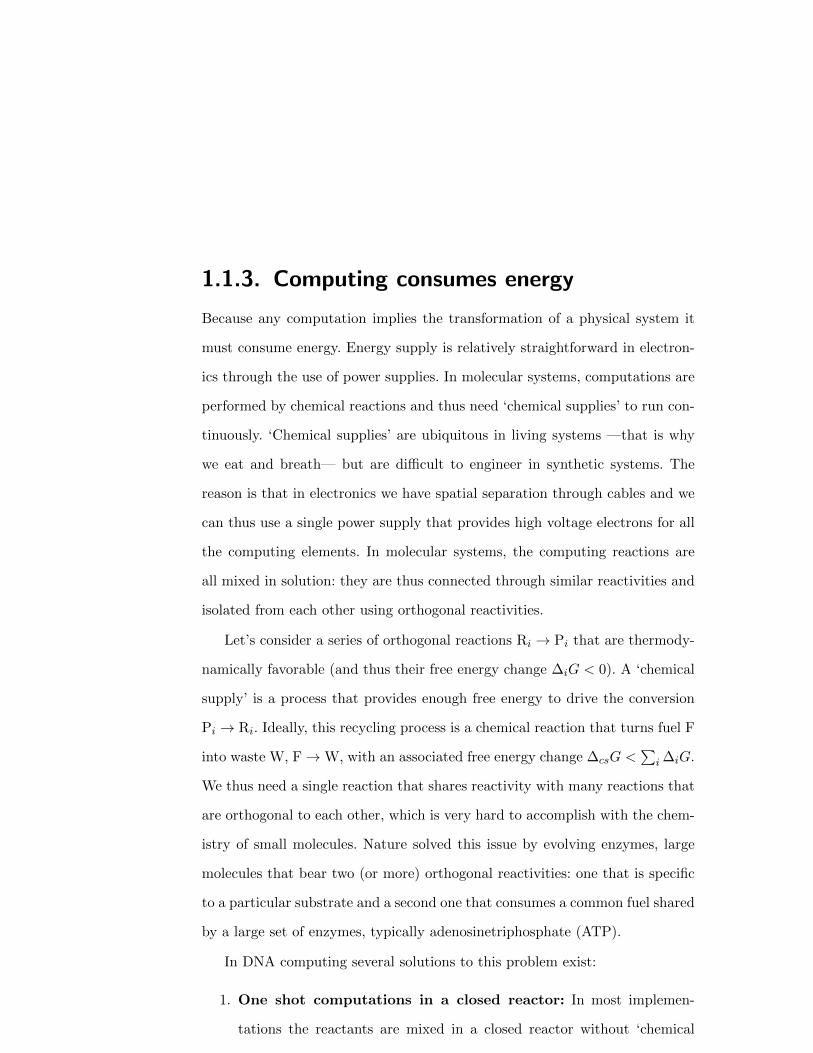
1.1.3. Computing consumes energy
Because any computation implies the transformation of a physical system it
must consume energy. Energy supply is relatively straightforward in electron-
ics through the use of power supplies. In molecular systems, computations are
performed by chemical reactions and thus need ‘chemical supplies’ to run con-
tinuously. ‘Chemical supplies’ are ubiquitous in living systems —that is why
we eat and breath— but are difficult to engineer in synthetic systems. The
reason is that in electronics we have spatial separation through cables and we
can thus use a single power supply that provides high voltage electrons for all
the computing elements. In molecular systems, the computing reactions are
all mixed in solution: they are thus connected through similar reactivities and
isolated from each other using orthogonal reactivities.
Let’s consider a series of orthogonal reactions Ri → Pi that are thermody-
namically favorable (and thus their free energy change ∆iG < 0). A ‘chemical
supply’ is a process that provides enough free energy to drive the conversion
Pi → Ri. Ideally, this recycling process is a chemical reaction that turns fuel F
into waste W, F→W, with an associated free energy change ∆csG <∑
i ∆iG.
We thus need a single reaction that shares reactivity with many reactions that
are orthogonal to each other, which is very hard to accomplish with the chem-
istry of small molecules. Nature solved this issue by evolving enzymes, large
molecules that bear two (or more) orthogonal reactivities: one that is specific
to a particular substrate and a second one that consumes a common fuel shared
by a large set of enzymes, typically adenosinetriphosphate (ATP).
In DNA computing several solutions to this problem exist:
1. One shot computations in a closed reactor: In most implemen-
tations the reactants are mixed in a closed reactor without ‘chemical
4
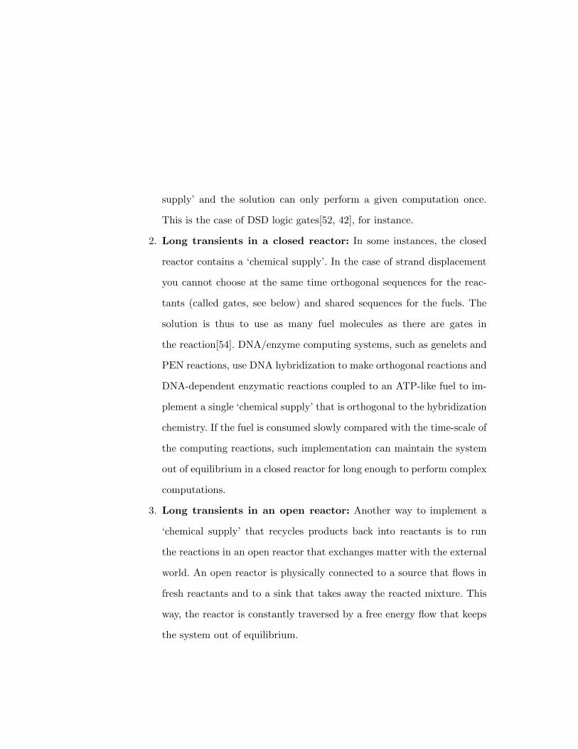
supply’ and the solution can only perform a given computation once.
This is the case of DSD logic gates[52, 42], for instance.
2. Long transients in a closed reactor: In some instances, the closed
reactor contains a ‘chemical supply’. In the case of strand displacement
you cannot choose at the same time orthogonal sequences for the reac-
tants (called gates, see below) and shared sequences for the fuels. The
solution is thus to use as many fuel molecules as there are gates in
the reaction[54]. DNA/enzyme computing systems, such as genelets and
PEN reactions, use DNA hybridization to make orthogonal reactions and
DNA-dependent enzymatic reactions coupled to an ATP-like fuel to im-
plement a single ‘chemical supply’ that is orthogonal to the hybridization
chemistry. If the fuel is consumed slowly compared with the time-scale of
the computing reactions, such implementation can maintain the system
out of equilibrium in a closed reactor for long enough to perform complex
computations.
3. Long transients in an open reactor: Another way to implement a
‘chemical supply’ that recycles products back into reactants is to run
the reactions in an open reactor that exchanges matter with the external
world. An open reactor is physically connected to a source that flows in
fresh reactants and to a sink that takes away the reacted mixture. This
way, the reactor is constantly traversed by a free energy flow that keeps
the system out of equilibrium.
5

1.1.4. Molecules compute in space through reaction-
diffusion primitives
In this chapter we will review recent examples of spatial computations per-
formed with DNA programs using reaction-diffusion primitives, because this
mechanism is pervasive to reacting molecules in solution[30]. We will not
discuss patterns created by DNA-programs in the absence of diffusion, such
as those driven by self-assembly processes in DNA nanostructures, or pat-
terned materials created from them, which are reviewed elsewhere[71, 22, 50],
nor reaction-diffusion patterns generated by protein[33, 84] or transcription-
translation networks[23, 57]. We further refer the interested reader to a recent
review on pattern generation with DNA programs[67].
In the absence of space (for instance if the reactor is well mixed), the prim-
itives of molecular computing are ruled by the kinetics of chemical reactions.
For instance, the reaction of two single-stranded DNA (ssDNA) A and B to
give the double strand C is written
A + Bk1k2
C (1.1)
where k1 and k2 are the hybridization and dehybridization kinetic rate con-
stants, respectively. Supposing mass-action law kinetics, the temporal evolution
of the concentration of species C is given by
dC
dt= k1A ·B − k2C (1.2)
where the concentration of a given species is noted in italics. Eq. 1.2, together
with similar equations for species A and B, are the computing primitives of a
6
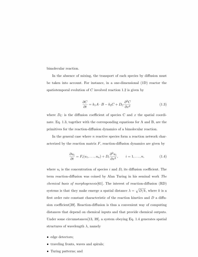
bimolecular reaction.
In the absence of mixing, the transport of each species by diffusion must
be taken into account. For instance, in a one-dimensional (1D) reactor the
spatiotemporal evolution of C involved reaction 1.2 is given by
∂C
∂t= k1A ·B − k2C +DC
∂2C
∂x2(1.3)
where DC is the diffusion coefficient of species C and x the spatial coordi-
nate. Eq. 1.3, together with the corresponding equations for A and B, are the
primitives for the reaction-diffusion dynamics of a bimolecular reaction.
In the general case where n reactive species form a reaction network char-
acterized by the reaction matrix F , reaction-diffusion dynamics are given by
∂ui∂t
= Fi(u1, . . . , un) +Di∂2ui∂x2
, i = 1, . . . , n, (1.4)
where ui is the concentration of species i and Di its diffusion coefficient. The
term reaction-diffusion was coined by Alan Turing in his seminal work The
chemical basis of morphogenesis[61]. The interest of reaction-diffusion (RD)
systems is that they make emerge a spatial distance λ =√D/k, where k is a
first order rate constant characteristic of the reaction kinetics and D a diffu-
sion coefficient[39]. Reaction-diffusion is thus a convenient way of computing
distances that depend on chemical inputs and that provide chemical outputs.
Under some circumstances[13, 39], a system obeying Eq. 1.4 generates spatial
structures of wavelength λ, namely
• edge detectors;
• traveling fronts, waves and spirals;
• Turing patterns; and
7

• stationary fronts and band patterns.
All these patterns have been observed and investigated, principally be-
tween 1970 and 2000, with reactions based on the redox chemistry of small
molecules, of which an archetypal example is the Belousov-Zhabotinsky (BZ)
oscillator[14]. However, redox chemistry is not programmable and its harsh
acidic conditions make it incompatible with biological materials. Engineering
RD patterns with DNA programs solves these two issues. In sections 1.3 to 1.4
we will see how these patterns —except Turing ones— have been engineered
with DNA programs.
1.2. Experimental implementation of DNA
analog circuits
In this section we discuss the three DNA-based experimental systems that can
currently perform analog computations coupled to a ‘chemical supply’ and that
are thus amenable to non-trivial reaction-diffusion computing: DNA strand
displacement, genelets and PEN reactions. We review them by showing how to
implement a cornerstone of non-equilibrium dynamics: a chemical oscillator.
1.2.1. DNA strand displacement oscillators
Toehold-mediated DNA strand displacement was developed by Yurke, Turber-
field and collaborators as a way to use ssDNA as a catalyst to fuel DNA-based
nanomachines[73, 59]. Their simple and powerful idea was to control the kinet-
ics of dsDNA dehybridization through a hybridization event: if the partially
8
1 2 3+
A
89
5 62 3 4
3*2*1* 6*5*
5 6
3*2*1* 6*5*
1 2 32 3 4
+
5 6
3*2*1* 6*5*
1 2 3 4 5 6
C
4*4*
4* 3*2*1* 6*5*
1 2 3 4 5 6
4*
5 6+
5 6
+
+
10 11 10 11
10 11 11
11
12 10 12
89
7*11*6*
B5
6 11
+
RACIB
IB
IBRI BB
+ A C B+ RACIB+ IB
WACIB
WACIB+
RI BB+
WI BB
WI BB+a)
b)
A C Bc)
d)
11 7 11 7
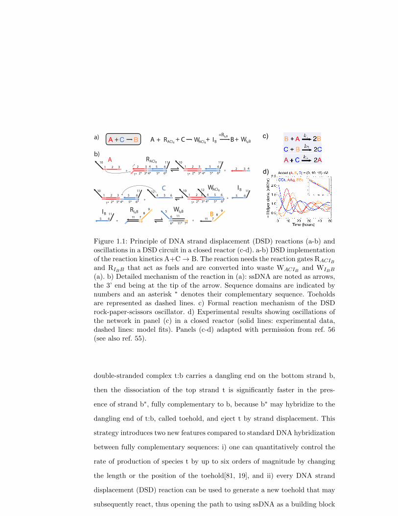
Figure 1.1: Principle of DNA strand displacement (DSD) reactions (a-b) andoscillations in a DSD circuit in a closed reactor (c-d). a-b) DSD implementationof the reaction kinetics A+C→ B. The reaction needs the reaction gates RACIB
and RIBB that act as fuels and are converted into waste WACIB and WIBB
(a). b) Detailed mechanism of the reaction in (a): ssDNA are noted as arrows,the 3’ end being at the tip of the arrow. Sequence domains are indicated bynumbers and an asterisk ∗ denotes their complementary sequence. Toeholdsare represented as dashed lines. c) Formal reaction mechanism of the DSDrock-paper-scissors oscillator. d) Experimental results showing oscillations ofthe network in panel (c) in a closed reactor (solid lines: experimental data,dashed lines: model fits). Panels (c-d) adapted with permission from ref. 56(see also ref. 55).
double-stranded complex t:b carries a dangling end on the bottom strand b,
then the dissociation of the top strand t is significantly faster in the pres-
ence of strand b∗, fully complementary to b, because b∗ may hybridize to the
dangling end of t:b, called toehold, and eject t by strand displacement. This
strategy introduces two new features compared to standard DNA hybridization
between fully complementary sequences: i) one can quantitatively control the
rate of production of species t by up to six orders of magnitude by changing
the length or the position of the toehold[81, 19], and ii) every DNA strand
displacement (DSD) reaction can be used to generate a new toehold that may
subsequently react, thus opening the path to using ssDNA as a building block
9

of chemical reaction networks.
Although DSD reactions were first applied to digital computing by Winfree
and collaborators[52, 42, 82] they can also be used in analog computations.
This was first proposed theoretically in 2010[54] and recently demonstrated
experimentally by synthesizing a DSD oscillator[55]. To design DSD analog
computations, one first chooses a suitable formal mechanism. As an example,
let’s consider the bimolecular reaction A + C → B. Species A, C and B are
encoded with ssDNA strands composed of a species-specific and a reaction-
specific domain (respectively colored and black in Fig. 1.1a). The reaction
is implemented in two steps with two gates RACIB and RIBB (Figure 1.1a),
which are DNA complexes composed of two or more partially-hybridized DNA
strands bearing reactive toeholds. First, the step A + C→ IB is implemented
by RACIB that is an AND gate that produces intermediate IB in the presence
of both A and C. A second gate RIBB takes the released species IB as an input
and produces B.
Autocatalytic reactions of the type A + B → 2A can be experimentally
implemented by using a gate that takes two different inputs and generates
two identical outputs[55]. The leak inherent to any autocatalytic reaction may
be efficiently suppressed by adding a thresholding module that suppresses the
output that detaches from the gate in the absence of the input. By connect-
ing three of these autocatalytic modules that repressed each other, Srinivas,
Soloveichick and collaborators[55] succeeded the tour-de-force of synthesizing a
DSD oscillator in a closed reactor, thus proving for the first time that complex
analog networks with feedbacks can be built and kept out of equilibrium with
DSD reactions (Figure 1.1b).
10
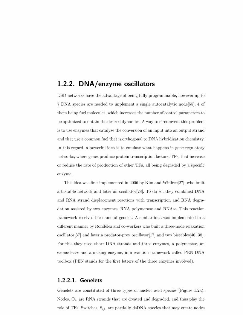
1.2.2. DNA/enzyme oscillators
DSD networks have the advantage of being fully programmable, however up to
7 DNA species are needed to implement a single autocatalytic node[55], 4 of
them being fuel molecules, which increases the number of control parameters to
be optimized to obtain the desired dynamics. A way to circumvent this problem
is to use enzymes that catalyse the conversion of an input into an output strand
and that use a common fuel that is orthogonal to DNA hybridization chemistry.
In this regard, a powerful idea is to emulate what happens in gene regulatory
networks, where genes produce protein transcription factors, TFs, that increase
or reduce the rate of production of other TFs, all being degraded by a specific
enzyme.
This idea was first implemented in 2006 by Kim and Winfree[27], who built
a bistable network and later an oscillator[28]. To do so, they combined DNA
and RNA strand displacement reactions with transcription and RNA degra-
dation assisted by two enzymes, RNA polymerase and RNAse. This reaction
framework receives the name of genelet. A similar idea was implemented in a
different manner by Rondelez and co-workers who built a three-node relaxation
oscillator[37] and later a predator-prey oscillator[17] and two bistables[40, 38].
For this they used short DNA strands and three enzymes, a polymerase, an
exonuclease and a nicking enzyme, in a reaction framework called PEN DNA
toolbox (PEN stands for the first letters of the three enzymes involved).
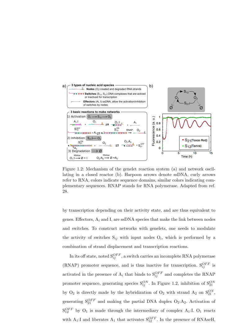
1.2.2.1. Genelets
Genelets are constituted of three types of nucleic acid species (Figure 1.2a).
Nodes, Oi, are RNA strands that are created and degraded, and thus play the
role of TFs. Switches, Sij , are partially dsDNA species that may create nodes
11
b)
++O1A1:I O1:I A1
+ A1
S12 RNAP
1) Activation
2) Inhibition
O2
O2:A2
+
Ø + IRNAse
3) Degradation
O1:I
a)
3 basic reactions to make networks
S21
S12
Flu
ores
cenc
e (
a. u
.)
3 types of nucleic acid speciesNodes (Oi) created and degraded RNA strands
Switches (S12, S21) DNA complexes that are actived or inactived for transcription
Effectors (Ai, I) ssDNA, allow the activation/inhibition of switches by nodes
O1 O2
ØØ
O2+
OFF ON
ON
OFF
Ø +A2
RNAse
O2:A2
S12
S21
S12
S21S21
Ø
O2S21
S12O1 O2
A2
Figure 1.2: Mechanism of the genelet reaction system (a) and network oscil-lating in a closed reactor (b). Harpoon arrows denote ssDNA, curly arrowsrefer to RNA, colors indicate sequence domains, similar colors indicating com-plementary sequences. RNAP stands for RNA polymerase. Adapted from ref.28.
by transcription depending on their activity state, and are thus equivalent to
genes. Effectors, Ai and I, are ssDNA species that make the link between nodes
and switches. To construct networks with genelets, one needs to modulate
the activity of switches Sij with input nodes Oi, which is performed by a
combination of strand displacement and transcription reactions.
In its off state, noted SOFFij , a switch carries an incomplete RNA polymerase
(RNAP) promoter sequence, and is thus inactive for transcription. SOFFij is
activated in the presence of Ai that binds to SOFFij and completes the RNAP
promoter sequence, generating species SONij . In Figure 1.2, inhibition of SON
21
by O2 is directly made by the hybridization of O2 with strand A2 on SON21 ,
generating SOFF21 and making the partial DNA duplex O2:A2. Activation of
SOFF12 by O1 is made through the intermediary of complex A1:I. O1 reacts
with A1:I and liberates A1 that activates SOFF12 . In the presence of RNAseH,
12
which specifically degrades RNA hybridized to DNA, species O1:I and O2:A2
continuously regenerate I and A2 and destroy the nodes Oi. The production
of RNA by consuming nucleotidetriphosphates, NTPs, and its degradation
through RNAse ensure that the network is kept out of equilibrium for 10-15
hours in a closed reactor. Genelets have been used to construct bistable[27, 51]
and oscillatory networks[28, 16].
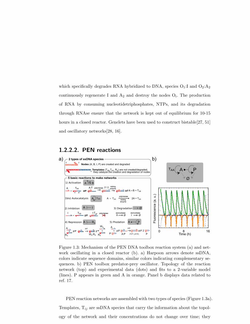
1.2.2.2. PEN reactionsF
luor
esce
nce
(a.
u.)
Time (h)0 8 16
a) b)
A Ø I Øexonuclease exonuclease
3) Degradation
4) Repression
IA Ø
AA
1) Activation
nickingenzymeTAB
B + TAB
polymerase
+ +A* B*
TCGAGTCTGTT
AGCTCAGACAATACTCAGTACG
A BTAB
Nodes (A, B, I, P) are created and degraded
Templates (TAB,TAA, RA) are not created/degraded,they catalyze the creation and degradation of nodes
5 basic reactions to make networks
5' 3'
5'3'
TAB+
I
polymeraseA:T
I:T
T*:T
2 types of ssDNA species
1bis) Autocatalysis TAAA Anickingenzyme
TAA 2A + TAA
polymerase+
RAA
+A
RA
pol
+
WA
RAWA:RA
2) Inhibition
+
A
P
pol
P:P* (=P:P)
5) Predation PA
A:P P
2
PATAA
Ø
Figure 1.3: Mechanism of the PEN DNA toolbox reaction system (a) and net-work oscillating in a closed reactor (b). a) Harpoon arrows denote ssDNA,colors indicate sequence domains, similar colors indicating complementary se-quences. b) PEN toolbox predator-prey oscillator. Topology of the reactionnetwork (top) and experimental data (dots) and fits to a 2-variable model(lines). P appears in green and A in orange. Panel b displays data related toref. 17.
PEN reaction networks are assembled with two types of species (Figure 1.3a).
Templates, Tij are ssDNA species that carry the information about the topol-
ogy of the network and their concentrations do not change over time; they
13

are equivalent to genes. Nodes (A, B, I) are shorter ssDNA strands that are
processed and created by the templates, they are both produced and degraded
over time; they play the role to TFs. These two species, together with 3 en-
zymes, can perform five types of reactions in the presence of dNTPs: activation,
inhibition, degradation, repression and predation.
Template TAB catalyses the activation reaction A→ A + B, where A and
B are nodes. TAB is typically 20-25 nt-long and it carries two sequence do-
mains, the input domain, of sequence A∗, and the output domain, noted B∗,
respectively complementary to A and B. Nodes are typically 10-15 nt-long.
During activation, A binds to the input site of TAB to form species A:TAB,
which is extended by a DNA polymerase, pol, into dsDNA species T∗AB:TAB
(T∗AB has the sequence A–B). A nicking enzyme, nick, recognizes a 5 or 6 nt-
long sequence on T∗AB:TAB and cuts the upper strand T∗AB between domains
A and B, which dehybridizes into species A, B and TAB. The temperature
is chosen in the range 37–45o such that the complex A:TAB is close to the
melting temperature but T∗AB:TAB is stable. Autocatalysis can be encoded in
an activation template TAA whose input and output domains are identical.
Note that, as it happens with any autocatalytic reaction, PEN autocataly-
sis ‘leaks’, i.e. it starts in the absence of input A, because the polymerase is
able to synthesize A in the absence of template[86]. In standard conditions
this leak happens within 100 min, but it can be simply reduced in the pres-
ence of high concentrations of nicking enzyme to reach 10 h, and even totally
suppressed in the presence of repression (see below), which turns the monos-
table autocatalytic node into a bistable one[38]. A second side-reaction of PEN
autocatalysis is the generation of autocatalytic parasites, which result from un-
templated autocatalysis[86]. This reaction generates mixtures of DNA strands
14
spanning ten to several thousands nucleotides that ultimately break the de-
signed dynamics of PEN networks at long times. Depending on the conditions,
parasites emerge after 5 to 50 h. However, these parasites may be suppressed
from functional PEN networks by adopting a three-letter encoding[63].
Inhibition of TAB is performed by strand I, typically 15 nt-long, that par-
tially hybridizes to domains A∗ and B∗ on T, forming I:T. A single-stranded
overhang on the 3’ end of I bound to TAB precludes the polymerase to extend
it, and a careful choice of its sequence, prevents nick from cutting it. Degra-
dation of nodes is performed by a single-stranded DNA exonuclease that does
not degrade templates because they are chemically modified on their 5’ end.
Repression of an autocatalytic node can be implemented by adding a template
RA that takes A as an input and adds a short sequence to its 3’ end, converting
it into a waste product, WA, unable to react with the template TAA. In this
configuration, when RA is a degradable node with palindromic sequence, noted
P, a predation reaction of the type A+P→ 2P can be implement. To construct
a network, activating and inhibiting links are selected such that the sequence of
output B is, respectively, the input or the inhibitor of a downstream template.
The continuous production and degradation of node strands, which consumes
deoxynucleotidetriphosphates, dNTPs, keeps the network out of equilibrium in
a closed reactor.
The PEN toolbox has produced so far oscillators that are significantly more
robust than those reported using genelets (Figures 1.2b and 1.3b). The two-
and three-node genelet oscillators[28, 16] oscillate for 6 periods during 20 h
and for 3 periods during 15h, respectively. In contrast, the two-node predator-
prey[17] and the three-node oligator[37] PEN oscillators oscillate for 26 periods
for 32 h and for 18 periods during 30 h, respectively. Unpublished results with
15
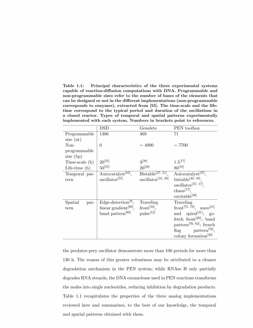
Table 1.1: Principal characteristics of the three experimental systemscapable of reaction-diffusion computations with DNA. Programmable andnon-programmable sizes refer to the number of bases of the elements thatcan be designed or not in the different implementations (non-programmablecorresponds to enzymes), extracted from [55]. The time-scale and the life-time correspond to the typical period and duration of the oscillations ina closed reactor. Types of temporal and spatial patterns experimentallyimplemented with each system. Numbers in brackets point to references.
DSD Genelets PEN toolbox
Programmablesize (nt)
1386 469 71
Non-programmablesize (bp)
0 ∼ 4000 ∼ 7700
Time-scale (h) 20[55] 3[28] 1.5[17]
Life-time (h) 50[55] 20[28] 80[18]
Temporal pat-tern
Autocatalyst[83],oscillator[55]
Bistable[27, 51],oscillator[16, 28]
Autocatalyst[37],bistable[40, 38],oscillator[37, 17],chaos[17],excitable[38]
Spatial pat-tern
Edge-detection[8],linear gradient[80],band pattern[80]
Travelingfront[53],pulse[12]
Travelingfront[75, 78], wave[41]
and spiral[41]; go-fetch front[20]; bandpattern[76, 62]; frenchflag pattern[76],colony formation[20]
the predator-prey oscillator demonstrate more than 100 periods for more than
130 h. The reason of this greater robustness may be attributed to a cleaner
degradation mechanism in the PEN system; while RNAse H only partially
degrades RNA strands, the DNA exonuclease used in PEN reactions transforms
the nodes into single nucleotides, reducing inhibition by degradation products.
Table 1.1 recapitulates the properties of the three analog implementations
reviewed here and summarizes, to the best of our knowledge, the temporal
and spatial patterns obtained with them.
16
1.3. Time-dependent spatial patterns
In this section we review experimental realizations of spatial calculations which
output is a spatial concentration pattern that depends on time. We will first
see how an incoherent feed forward loop network performs edge detection and
how an autocatalytic program generates propagating concentration fronts. We
will then describe go-fetch fronts that are able to interrogate the presence of a
particular DNA sequence at a distance, and traveling waves and spirals based
on DNA oscillators. Finally, we will review methods to control the diffusion
coefficient and the geometry of the environment where the spatial pattern
evolves.
1.3.1. Edge detection
Reaction-diffusion programs can perform some image-processing algorithms
where the input and output are images encoded as concentration patterns. This
was first demonstrated using the Belousov-Zhabotinsky reaction in 1989[31]. In
2013, Chen, Ellington and co-workers engineered DNA reaction networks that
detected the edge of an input image (Figure 1.4)[8]. The computation was
performed by a reaction network where the input I comes in the form of light,
and A, B and C are DNA strands. On the one side, I activates A and triggers
the cascade A → B → C. On the other side, I inhibits B and thus inhibits de
cascade B → C. Because I activates and inhibits C, such network is called an
incoherent feed forward loop (IFFL). In addition, A needs to diffuse faster than
B and C. Let’s now consider that we illuminate the medium with a pattern
with a border between light and no light (1/0, Figure 1.4a). The illuminated
zone will produce A and destroy B, and thus no output C will be observed in
17
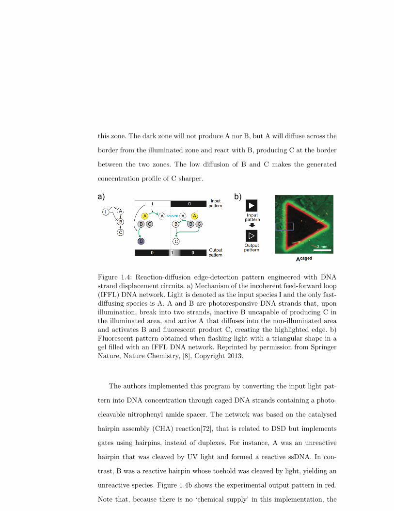
this zone. The dark zone will not produce A nor B, but A will diffuse across the
border from the illuminated zone and react with B, producing C at the border
between the two zones. The low diffusion of B and C makes the generated
concentration profile of C sharper.
a) b)
3 mm
Figure 1.4: Reaction-diffusion edge-detection pattern engineered with DNAstrand displacement circuits. a) Mechanism of the incoherent feed-forward loop(IFFL) DNA network. Light is denoted as the input species I and the only fast-diffusing species is A. A and B are photoresponsive DNA strands that, uponillumination, break into two strands, inactive B uncapable of producing C inthe illuminated area, and active A that diffuses into the non-illuminated areaand activates B and fluorescent product C, creating the highlighted edge. b)Fluorescent pattern obtained when flashing light with a triangular shape in agel filled with an IFFL DNA network. Reprinted by permission from SpringerNature, Nature Chemistry, [8], Copyright 2013.
The authors implemented this program by converting the input light pat-
tern into DNA concentration through caged DNA strands containing a photo-
cleavable nitrophenyl amide spacer. The network was based on the catalysed
hairpin assembly (CHA) reaction[72], that is related to DSD but implements
gates using hairpins, instead of duplexes. For instance, A was an unreactive
hairpin that was cleaved by UV light and formed a reactive ssDNA. In con-
trast, B was a reactive hairpin whose toehold was cleaved by light, yielding an
unreactive species. Figure 1.4b shows the experimental output pattern in red.
Note that, because there is no ‘chemical supply’ in this implementation, the
18
output pattern is transient and will fade away by diffusion after some time. To
our knowledge, this was the first experimental demonstration of RD patterns
programmed with DNA.
Complementary to edge detection, Abe et al. demonstrated the computa-
tion of a line segment equidistant from two source points[1]. These experiments
were also performed in a gel matrix. A DNA logic AND gate was anchored ev-
erywhere in the gel, and two holes made in the gel were filled with the gate
inputs. Both inputs diffused through the matrix, and activated the AND gate
only at the equidistant region from the source points; thus producing a Voronoi
pattern. More complex patterns were observed when multiple source points
were involved.
1.3.2. Traveling patterns
In the absence of reaction, the diffusion of a chemical species is quite boring:
a concentration profile will fade away until reaching a spatially homogeneous
final state, following Fick’s diffusion law. In contrast, in the presence of an
autocatalytic reaction, which is a transformation where the product cataly-
ses its own production, an inhomogeneous concentration profile will generate
concentration patterns that propagate, often with constant velocity. Traveling
patterns are an efficient way to convey chemical information across distances
where diffusion is too slow.
1.3.2.1. Fronts
The simplest traveling pattern is the front (a structure with a single low-to-high
concentration transition) that just needs a single autocatalytic loop, which we
19
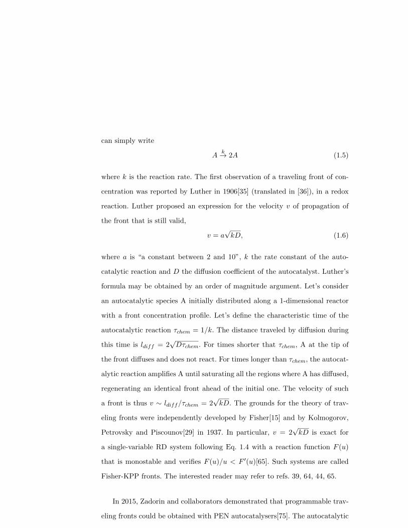
can simply write
Ak→ 2A (1.5)
where k is the reaction rate. The first observation of a traveling front of con-
centration was reported by Luther in 1906[35] (translated in [36]), in a redox
reaction. Luther proposed an expression for the velocity v of propagation of
the front that is still valid,
v = a√kD, (1.6)
where a is “a constant between 2 and 10”, k the rate constant of the auto-
catalytic reaction and D the diffusion coefficient of the autocatalyst. Luther’s
formula may be obtained by an order of magnitude argument. Let’s consider
an autocatalytic species A initially distributed along a 1-dimensional reactor
with a front concentration profile. Let’s define the characteristic time of the
autocatalytic reaction τchem = 1/k. The distance traveled by diffusion during
this time is ldiff = 2√Dτchem. For times shorter that τchem, A at the tip of
the front diffuses and does not react. For times longer than τchem, the autocat-
alytic reaction amplifies A until saturating all the regions where A has diffused,
regenerating an identical front ahead of the initial one. The velocity of such
a front is thus v ∼ ldiff/τchem = 2√kD. The grounds for the theory of trav-
eling fronts were independently developed by Fisher[15] and by Kolmogorov,
Petrovsky and Piscounov[29] in 1937. In particular, v = 2√kD is exact for
a single-variable RD system following Eq. 1.4 with a reaction function F (u)
that is monostable and verifies F (u)/u < F ′(u)[65]. Such systems are called
Fisher-KPP fronts. The interested reader may refer to refs. 39, 64, 44, 65.
In 2015, Zadorin and collaborators demonstrated that programmable trav-
eling fronts could be obtained with PEN autocatalysers[75]. The autocatalytic
20

behavior of node A growing on template TAA is demonstrated in Figure 1.5a,
where the concentration of A:TAA is measured by fluorescence in the presence
of a DNA intercalator and plotted vs. time. At short time (and thus low A) the
system behaves as A = A(0)ekt, where k is the rate constant of autocatalysis.
T+pol+ nick
Parafilm
A PropagationGreaseplug
walls
0
100
102
104
Flu
ore
sce
nce
inte
nsity
(a
.u.)
a) b) c)
200100
0 1 2 3
x (mm)
tim
e (
min
) 0
50
1000 4 8 12
x (mm)
tim
e (
min
) 0
100
200
B on TBBA on TAA
ATAA BTBB
A on TAA B on TBB
d) e)
A
A on Tt, min
ATAA
ATAA B TBBØ
TAA
Figure 1.5: PEN autocatalysers generate programmable concentration frontsthat travel at constant velocity. a) Temporal dynamics of a simple PEN auto-catalyser. The log-lin plot shows DNA intercalator fluorescence proportionalto the concentration of A, the initial linear slope indicates exponential growth.b) Sketch of the experimental setup to observe fronts. c-e) Kymographs ofthe fluorescence signal for different autocatalytic networks show a single front(c) and two counter-propagating fronts that either do not interact (d) or thatstrongly inhibit each other (e). Panels b and d reprinted with permission from[75] Copyright 2015 by the American Physical Society.
In a one-dimensional reactor such as the one depicted in Figure 1.5b —
filled homogeneously with a solution containing an TAA, pol, nick and dNTPs,
and containing an excess of autocatalytic node A on the left-hand-side— a
front propagating with uniform velocity, typically 60 µm min−1, was observed
through time-lapse fluorescence microscopy (Figure 1.5c). To check if the front
followed Luther’s equation 1.6, the velocity of the front was measured for dif-
21
ferent reaction rates k and different effective diffusion coefficients D. The rates
were controlled by changing the concentration of the template T0 (in a cer-
tain concentration range, k ∼ T0 in PEN reactions), while D was reduced
by attaching a hydrodynamic drag to the template strand (see below). In all
these cases, the measured velocities followed Luther’s scaling v = a√kD with
a = 2.6, both for k and D.
The programmability of this approach was illustrated by designing different
networks containing autocatalysis that resulted in controlled spatio-temporal
dynamics. Two autocatalysts with orthogonal sequences generated fronts that
cross-propagated with little interaction (Figure 1.5d). In contrast, two auto-
catalysts that cross-inhibited themselves created repelling cross-propagating
fronts (Figure 1.5e).
Note that traveling fronts have not yet been demonstrated with DSD net-
works even if autocatalytic networks exist[83, 72]. A possible reason is that it
is more difficult to control the leak of DSD autocatalysts compared to PEN
ones. Indeed if the autocatalytic reaction leaks, the area ahead of the front will
get triggered before the front arrives and homogeneous amplification will be
observed. However, considering that CHA autocatalysts may remain untrig-
gered for 3 h[72] and recent DSD autocatalysts are stable for tens of hours[55],
DNA-only traveling fronts may soon be observed. Finally, autocatalytic fronts
have also been observed in genelet networks[53], although it remains to be
tested that they verify Luther’s formula.
1.3.2.2. Go-fetch fronts
The above-mentioned spatiotemporal reaction networks operate with species
that freely diffuse in solution. It may also be possible to localize the reaction by
22
grafting the catalysts on different positions of a substrate. For instance, Gines
et al. used particle-bound DNA strands to spatialize the chemical reactions
in a fluidic chamber[20]. Here, the DNA templates were grafted via a biotin-
streptavidin linkage onto micrometric hydrogel particles, which results in the
localized production of output strands on the particles, while the degradation
happens in the whole reservoir.
Particles bearing a PEN autocatalyser generated a traveling front of con-
stant velocity. In addition, the authors reported a ‘go-fetch’ chemical system
that computes the distance between two specific DNA sequences through two
orthogonal traveling fronts (Figure 1.6a). This experimental implementation
uses 4 populations of DNA-programmed particles. The sender (SA) initiates
the production of strand A on the left side of the channel using a —leaky—
monostable autocatalytic loop. A first relay population (RA), grafted with
a bistable switch that amplifies A, transmits the signal across the chamber.
When the signal A comes across the receiver particle (CAB), placed on the
right side of the channel, it activates the production of strand B. This reaction
is catalysed by an activation template TAB that converts A into B. B finally
propagates through the second relay population (RB) until reaching SA, which
in turn exhibits a fluorescent signal. This system is programmed to compute
the distance between SA and CAB, which correlates with the time it takes to
the SA particles to fluoresce upon receiving the B strand. Interestingly, RD
enables long-distance communication (∼ 1cm), which is at least 3 orders of
magnitude larger than the particle size (∼ 10 µm). A limitation of this proto-
col is that the particles are randomly distributed in a microchamber, with a
poor control on the localization of the reactants. It would be interesting in the
future to implement the precise disposition of particles programmed with dif-
23

ferent sensing networks and build on these organized arrays to create tissue-like
systems.
c)
tim
e (m
in)
x (mm)
0
200
400
0 5 10
PTNN
Ø
b)
d)
a)
N
Figure 1.6: ‘Go-fetch’ fronts (a) and waves and spirals with PEN reactions(b-d). a) A ‘go-fetch’ program is implemented when PEN template strandsare attached to microparticles distributed in 4 populations: SA = sender par-ticle, RA and RB = relay particles, CAB = converter particles. When thesignal A transported by RA reaches CAB, it is converted to B that travelsback transported by RB to the initial position (top). The bottom kymographrepresents the go front in red and the reply front in green. b) Topology ofthe PEN predator-prey (PP) network. c) Kymograph of prey fluorescence ina 1-dimensional reactor. Oblique white lines correspond to traveling waves. d)Time-lapse fluorescent images of a prey (N) spiral turning around the black dot(false color). Panel (a) reprinted by permission from Springer Nature, NatureNanotechnology, [20], Copyright 2017. Panels (c,d) adapted with permissionfrom [41]. Copyright (2013) American Chemical Society.
1.3.2.3. Waves and spirals
An autocatalytic loop coupled to a delayed inhibition makes an oscillator that,
in the presence of diffusion, creates chemical waves and spirals that travel at
constant velocity[13]. Such patterns have been observed in the BZ oscillator in
the early 70s [77, 68] but have only recently been observed in DNA systems
24
with the PEN predator-prey (PP) oscillator[41].
The mechanism of the PP oscillator is simple and produces robust oscilla-
tions[17] (Figure 1.3b). Species N, the prey, grows autocatalytically on template
TNN . The trick is that species P, the predator, is both palindromic, i.e. it is
self-complementary, and contains the sequence of N (Figure 1.3a). When P and
N bind together, the polymerase extends N, yielding two P, and thus P grows
autocatalytically consuming the prey (N + P→ 2P). In addition N and P are
both degraded, mimicking the natural decay of preys and predators.
When a spatial reactor was filled with the PP mixture and the initial con-
centrations of N and P were homogeneous, traveling concentration waves of
prey, followed by predator waves were observed[41] (Figure 1.6c). The wave
velocities were in the range 80 − 400 µm min−1 and were in fair agreement
with a 2-variable model related with Eq. 1.6. When the initial condition of
prey was inhomogeneous, spirals were observed (Figure 1.6d). This was the
first report of traveling waves in a chemical reaction network built from the
bottom up. It was also the first observation of predator-prey waves in the
laboratory.
1.3.3. Controlling spatio-temporal patterns
We have seen in section 1.1.4 that the output of a reaction-diffusion computa-
tion is given by the solution to the system of partial differential equations in
Eq. 1.4. Such solution depends on four important features:
1. the topology of the reaction network, i.e. the function F in Eq. 1.4,
2. the reaction rates,
3. the diffusion coefficients,
25

4. the initial and boundary conditions.
We have just discussed some network topologies that provide different out-
puts: an incoherent feed forward loop (IFFL) that makes an edge detector or
an autocatalytic node that generates a traveling front, for instance. We have
also seen that reaction rates can be changed in DSD reactions by changing
the length of the toehold and in PEN reactions by tuning the concentration
of the template strands. Here we further discuss strategies to control diffusion
coefficients and initial and boundary conditions.
1.3.3.1. Controlling diffusion coefficients
The first strategy for reducing D is to increase the viscosity of the solution by
adding a viscous solute such as glycerol or polyethyleneglycol. The drawback
is that this method is not specific and all DNA species will be slowed down
by a similar factor. The second strategy is to perform the reaction inside a
sieving matrix, like a hydrogel, such that large DNA species will be trapped
and small ones will diffuse freely. This method was successfully used in the
edge detection network discussed above[8]. In this case the fast-diffusing strand
A was shorter than the other reagents (8 vs. 64 nt. long) and reactions were
performed in 20% crosslinked polyacrylamide gel, resulting in a striking 10-fold
difference in diffusion coefficient. The last strategy is to specifically change D
for a given species, which can be performed by attaching a DNA strand to a
hydrodynamic drag. This method was employed to modify the diffusion of PEN
autocatalysers, the drag being a triton micelle of ∼ 5 nm radius to which a
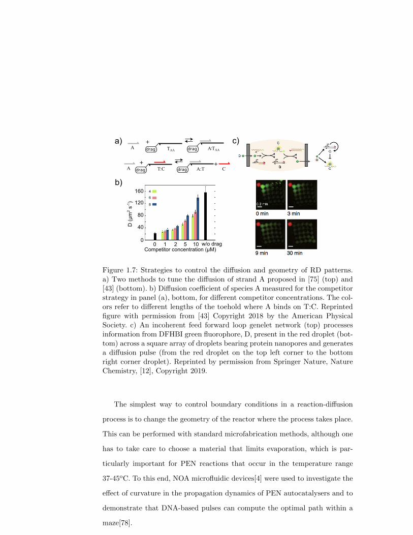
cholesteryl-modified template TAA was attached (Figure 1.7a). Autocatalyser
A needed to bind to TAA to grow and, depending on the molar fraction of
cholesteryl template, D was reduced up to 2.7-fold[75]. Importantly, not only
26

the effective diffusion of a passive solution was controlled but also the one of A
involved in a reaction-diffusion front, which was demonstrated by measuring
the velocity of the front.
An improved hydrodynamic drag was demonstrated by Rodjanapanyakul
et al. by using a linear copolymer of polyacrylamide and strand T [43], reaching
a reduction of D of 5-fold in DSD reactions, an approach also modeled by Allen
et al.[3]. With this stratefy the effective diffusion of freely-diffusing strand A,
complementary to T, could be modulated by changing the concentration of
a competitor strand C that also bound to T (Figure 1.7a,b)[43]. A similar
strategy was used to control the electrophoretic mobility of DNA involved in
DSD programs[2]. Recently, the copolymerization of DNA with polyacrylamide
was used to stablize PEN static RD patterns for more than 60 hours[62].
1.3.3.2. Initial and boundary conditions
In the aforementioned examples, the initial condition, or input signal, was in-
troduced either by adding a droplet of solution containing the input species,
which results in poor spatial resolution, or by using a light pattern, with high
spatial resolution. Other ways of controlling the initial condition include mi-
crofluidic injection using PDMS monolithic pumps[78] and electric switches[32].
In this last example, Kurylo et al. grafted an oligonucleotide on gold electrodes
embedded in microfluidic channels. They took advantage of the electrochemical
properties of the thiol-gold bond to release specific DNA localized in space and
time through a voltage pulse. In particular, the DNA release was able to trig-
ger PEN autocatalytic fronts. Without involving delicate liquid handling, this
method offers the possibility to control and interact in real time with running
DNA-based molecular systems.
27
b)
drag
+dragA TAA
a)
drag
+dragA T:C A:T
+C
Competitor concentration (µM)0 1 2 5 10 w/o drag
0
40
80
120
160
D (
µm
2 s-1
)
4
6
8
c)TAA A:
Figure 1.7: Strategies to control the diffusion and geometry of RD patterns.a) Two methods to tune the diffusion of strand A proposed in [75] (top) and[43] (bottom). b) Diffusion coefficient of species A measured for the competitorstrategy in panel (a), bottom, for different competitor concentrations. The col-ors refer to different lengths of the toehold where A binds on T:C. Reprintedfigure with permission from [43] Copyright 2018 by the American PhysicalSociety. c) An incoherent feed forward loop genelet network (top) processesinformation from DFHBI green fluorophore, D, present in the red droplet (bot-tom) across a square array of droplets bearing protein nanopores and generatesa diffusion pulse (from the red droplet on the top left corner to the bottomright corner droplet). Reprinted by permission from Springer Nature, NatureChemistry, [12], Copyright 2019.
The simplest way to control boundary conditions in a reaction-diffusion
process is to change the geometry of the reactor where the process takes place.
This can be performed with standard microfabrication methods, although one
has to take care to choose a material that limits evaporation, which is par-
ticularly important for PEN reactions that occur in the temperature range
37-45oC. To this end, NOA microfluidic devices[4] were used to investigate the
effect of curvature in the propagation dynamics of PEN autocatalysers and to
demonstrate that DNA-based pulses can compute the optimal path within a
maze[78].
28
An interesting alternative for controlling the geometry of RD patterns was
proposed by Dupin and Simmel[12] (Figure 1.7d). They distributed a genelet
reaction network inside a 2-dimensional array of microdroplets that were in-
terconnected by protein nanopores. These nanopores allowed the droplets to
exchange DFHBI, a small molecule that fluoresces when bound to the spinach
RNA aptamer, but hindered the DNA-program from leaving the DNA-imper-
meable droplets. By constructing an IFFL reaction network that takes DFHBI
as an input and produces the spinach aptamer as output, a transient pulse of
fluorescence across an array of droplets was observed in the presence of a seed
droplet with high concentration of DFHBI; which was reported both in 1 and
2 dimensions. With this clever idea, the authors obtained compartments that
displayed a certain degree of autonomy, and at the same time the capability to
exchange and process specific chemical information, mimicking cell-cell com-
munication in living tissues. For the moment, the messaging molecule, DFHBI,
cannot be amplified autocatalytically, and thus the propagation velocity v of
the fluorescent pulse was not constant, as in Luther’s formula, but is rather
expected to follow a diffusive scaling v ∼ 1/√t. We thus anticipate that devel-
oping strategies to transfer DNA-rich information across membrane droplets
will be an important question in the near future.
1.4. Steady-state spatial patterns
In the above we have discussed RD computations which output is time-dependent.
However, in many instances a time-independent output is desirable. This is
very challenging because diffusion will continuously dilute the output, so that
reaction needs to balance diffusion to create a steady-state pattern. Steady-
29
state RD patterns are observed during early embryo development, where a
robust output is needed. In addition, they can be useful to create synthetic
morphogenetic materials with a chemically-defined final shape.
1.4.1. Colony formation
Inter-cellular communication is a critical parameter to precisely orchestrate
tissue development and differentiation. In an attempt to emulate very prim-
itively these communication channels between different objects, Gines et al.
used DNA-programmed particles (cf. section 1.3.2.2) that exhibit synergism
and cooperativity (Figure 1.8). The system uses two types of particles, PAB
and PBA, that produce the output strand B from A, and conversely, using
PEN reactions. The particules are dispersed in a solution containing the PEN
exonuclease that degrades A and B, such that, when the particles are far from
each other, homogeneous degradation is stronger than local particle produc-
tion and no strand production is detected. However, when both particle types
are present in close proximity, their cross-activation outcompetes degradation
and both A and B are produced autocatalytically. The system evolves toward
a steady-state where sharp concentration profiles are drawn around clusters
of synergic particles, creating colony-like patterns in a large population of
thousands of particles, which last for over dozens of hours. Interestingly, these
colonies became more active as their density increased, suggesting long-distance
interactions between the colonies that reinforce each other, in addition to the
local synergic particle activation mechanism. Particle-based systems coupled
to RD thus enable to easily control the topography of the reactions to start
building large networks that display steady-state patterns. Although the par-
30
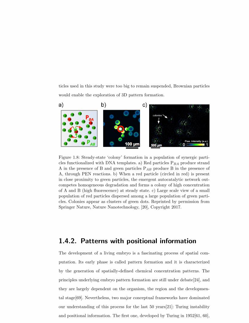
ticles used in this study were too big to remain suspended, Brownian particles
would enable the exploration of 3D pattern formation.
Figure 1.8: Steady-state ‘colony’ formation in a population of synergic parti-cles functionalized with DNA templates. a) Red particles PBA produce strandA in the presence of B and green particles PAB produce B in the presence ofA, through PEN reactions. b) When a red particle (circled in red) is presentin close proximity to green particles, the emergent autocatalytic network out-competes homogeneous degradation and forms a colony of high concentrationof A and B (high fluorescence) at steady state. c) Large scale view of a smallpopulation of red particles dispersed among a large population of green parti-cles. Colonies appear as clusters of green dots. Reprinted by permission fromSpringer Nature, Nature Nanotechnology, [20], Copyright 2017.
1.4.2. Patterns with positional information
The development of a living embryo is a fascinating process of spatial com-
putation. Its early phase is called pattern formation and it is characterized
by the generation of spatially-defined chemical concentration patterns. The
principles underlying embryo pattern formation are still under debate[24], and
they are largely dependent on the organism, the region and the developmen-
tal stage[69]. Nevertheless, two major conceptual frameworks have dominated
our understanding of this process for the last 50 years[21]: Turing instability
and positional information. The first one, developed by Turing in 1952[61, 60],
31

demonstrated that reaction-diffusion processes can form patterns. The second,
introduced by Wolpert in 1969[70], proposed a simple way to explain how cells
may compute their position within the embryo in the presence of a concen-
tration gradient. The principal difference between the two is that the Turing
instability is a symmetry-breaking mechanism that generates a heterogeneous
concentration state from a homogeneous one, while positional information is
a sharpening mechanism that amplifies a concentration heterogeneity from an
initial state where the symmetry has already been broken. While patterns of po-
sitional information have recently been engineered with DNA networks[76, 80],
DNA Turing patterns have yet to be demonstrated[79].
A BØ
Threshold M2
Threshold M
1
space (x)
A B
Morphogen
con
cen
tra
tion
Initial state Final state
con
cen
tra
tion
space
(M(x))
Figure 1.9: Illustration of Wolpert’s concept of positional information as asolution of the ‘French flag problem’ in the presence of a shallow gradient ofmorphogen concentration in a 1-dimensional embryo.
The idea of positional information was introduced by Wolpert to explain
how an embryo with a single break of symmetry could be further split into
several distinct regions[70]. He coined the term ‘French flag problem’ to illus-
trate the challenge —fundamental because it is pervasive in the development
of virtually all complex organisms— of creating three distinct regions of space
with sharp borders from an amorphous mass and a shallow concentration gra-
32
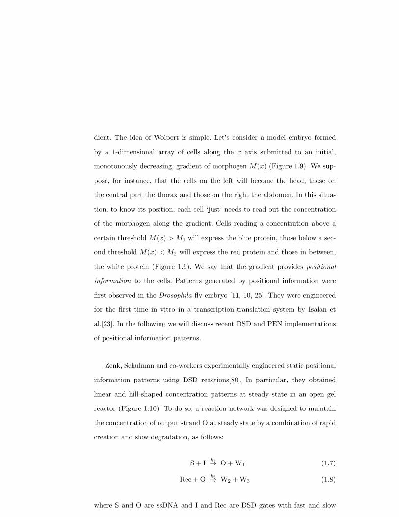
dient. The idea of Wolpert is simple. Let’s consider a model embryo formed
by a 1-dimensional array of cells along the x axis submitted to an initial,
monotonously decreasing, gradient of morphogen M(x) (Figure 1.9). We sup-
pose, for instance, that the cells on the left will become the head, those on
the central part the thorax and those on the right the abdomen. In this situa-
tion, to know its position, each cell ‘just’ needs to read out the concentration
of the morphogen along the gradient. Cells reading a concentration above a
certain threshold M(x) > M1 will express the blue protein, those below a sec-
ond threshold M(x) < M2 will express the red protein and those in between,
the white protein (Figure 1.9). We say that the gradient provides positional
information to the cells. Patterns generated by positional information were
first observed in the Drosophila fly embryo [11, 10, 25]. They were engineered
for the first time in vitro in a transcription-translation system by Isalan et
al.[23]. In the following we will discuss recent DSD and PEN implementations
of positional information patterns.
Zenk, Schulman and co-workers experimentally engineered static positional
information patterns using DSD reactions[80]. In particular, they obtained
linear and hill-shaped concentration patterns at steady state in an open gel
reactor (Figure 1.10). To do so, a reaction network was designed to maintain
the concentration of output strand O at steady state by a combination of rapid
creation and slow degradation, as follows:
S + Ik1→ O + W1 (1.7)
Rec + Ok2→ W2 + W3 (1.8)
where S and O are ssDNA and I and Rec are DSD gates with fast and slow
33
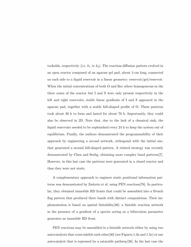
toeholds, respectively (i.e. k1 � k2). The reaction-diffusion pattern evolved in
an open reactor composed of an agarose gel pad, about 1-cm long, connected
on each side to a liquid reservoir in a linear geometry: reservoir/gel/reservoir.
When the initial concentrations of both O and Rec where homogeneous in the
three zones of the reactor but I and S were only present respectively in the
left and right reservoirs, stable linear gradients of I and S appeared in the
agarose pad, together with a stable hill-shaped profile of O. These patterns
took about 30 h to form and lasted for about 70 h. Importantly, they could
also be observed in 2D. Note that, due to the lack of a chemical sink, the
liquid reservoirs needed to be replenished every 24 h to keep the system out of
equilibrium. Finally, the authors demonstrated the programmability of their
approach by engineering a second network, orthogonal with the initial one,
that generated a second hill-shaped pattern. A related strategy was recently
demonstrated by Chen and Seelig, obtaining more complex band patterns[7].
However, in this last case the patterns were generated in a closed reactor and
thus they were not static.
A complementary approach to engineer static positional information pat-
terns was demonstrated by Zadorin et al. using PEN reactions[76]. In particu-
lar, they obtained immobile RD fronts that could be assembled into a French
flag pattern that produced three bands with distinct compositions. Their im-
plementation is based on spatial bistability[46]: a bistable reaction network
in the presence of a gradient of a species acting as a bifurcation parameter
generates an immobile RD front.
PEN reactions may be assembled in a bistable network either by using two
autocatalysts that cross-inhibit each other[40] (see Figures 1.3a and 1.5e) or one
autocatalyst that is repressed by a saturable pathway[38]. In the last case the
34
c)a)
b)
Sig
nal p
ropo
rtio
nal t
o [O
]
x (mm)
IS O
RecO
Figure 1.10: Static pattern of positional information engineered with DNAstrand displacement circuits. a) Reaction mechanism of the DSD network usedto maintain a steady-state concentration of strand O. b) Open gel reactor withliquid reservoirs on each side. The pattern is observed inside the gel pad. c)Dynamics of the hill-shaped pattern of species O obtained inside the gel reactorwhen the left reservoir contained species I, the right reservoir contained speciesS and Rec was distributed homogeneously. Adapted with permission from ref.80. Published by The Royal Society of Chemistry.
network is composed of the autocatalytic production of A by its template TAA
(as in Fig. 1.5a), the degradation of A by the exonuclease and its repression
by RA that converts it into waste (see Figures 1.3a and 1.11a). This system is
bistable because at low A, autocatalysis is slower than repression but at high
A (typically A > RA), the repression reaction saturates and shuts off. As a
result the concentration of RA acts as a bifurcation parameter.
Because PEN networks can be kept out of equilibrium for tens of hours in
a closed reactor, implementing positional information is relatively straightfor-
ward: one just needs to fill a channel with a bistable network and generate a
gradient of RA along the channel (Figure 1.11b). The authors used a 5 cm-long
glass capillary where a gradient of morphogen RA was generated using Tay-
lor dispersion[58, 62]. This way, the gradient was set up within minutes but
remained stable for tens of hours, because diffusion over centimeter scales is
very slow. With such an experimental setting, several multistable PEN net-
35

Figure 1.11: Static patterns of positional information can be engineered withPEN reactors and coupled to a simple material. a) Tetrastable network withautocatalytic nodes A, B and repressor RA-RB used to create a three bandFrench flag pattern. Enclosed in dashed lines the bistable network that createsa two-band pattern. b) Photograph of the closed reactor where the patternswhere obtained: a glass channel with a stable gradient of RA-RB (in blue). c)A tetrastable network in panel a forms a French flag pattern with three zonesof different composition in the presence of a gradient of the correspondingrepressor. The top image represents the stable underlying gradient concentra-tion profile (in blue) and a kymograph of DNA fluorescence inside the channel.When the channel is initially filled with a homogeneous dispersion of DNA-decorated colloids, the reaction-network can be designed to specifically controlthe aggregation of the beads (bottom images). Reprinted by permission fromSpringer Nature, Nature Chemistry, [76], Copyright 2017.
works were tested with different repressor gradients, and a variety of steady-
state band patterns were observed: an immobile front, two immobile fronts
that repel each other and two immobile fronts that form a French flag pat-
tern (Figure 1.11c). All the patterns self-organized in the same way: first a
reaction-only phase generated a mobile front on the side of the channel where
activation was stronger than repression, then the front(s) traveled through a
reaction-diffusion mechanism towards the repression side, slowing down until a
36

RD steady-state was obtained. In addition, the borders of the bands were one
order of magnitude sharper than the initial gradients (typically 1 mm com-
pared with 1 cm). However, PEN autocatalytic parasites (see section 1.2.2.2)
broke down the steady-state pattern after 10 h. This problem has recently
been solved by constructing parasite-robust PEN networks[63] that are able to
generate steady-state patterns that last for several days[62].
Pattern formation in the embryo is used for spatially-controlling subsequent
developmental steps, such as cell differentiation. If we consider the embryo as
a complex material and development as a self-fabrication process, the pattern
would be the self-fabricated blueprint. Zadorin et al. emulated this idea in a
very simple artificial system by coupling their PEN French flag pattern with
the conditional aggregation of DNA-decorated colloids[76]. As a result, the
DNA reaction-diffusion patterns just evoked differentiated an initially homo-
geneous material —a suspension of 1 µm colloids— into different zones with
different microscopic structures (Figure 1.11c). Recently, Urtel et al. were able
to maintain these band patterns at steady-state inside an autonomous hy-
drogel material[62], opening the way to building self-patterning autonomous
materials.
1.5. Conclusion and perspectives
We have seen in this chapter that DNA circuits are well-suited to perform ba-
sic spatial computations. We have focused on computations that use reaction-
diffusion primitives, which are the most natural operations that molecules per-
form in solution and, in particular, in illustrating their experimental implemen-
tations. The majority of DNA spatial computations involve analog circuits and
37
we have briefly discussed three of them: DNA strand displacement networks,
genelets and PEN DNA reactions, all capable of generating oscillations in a
closed reactor. DSD circuits have the advantage of being fully programmable
because there are tools to predict the thermodynamics and kinetics of DNA
hybridization reactions[85, 74, 34]. However, engineering ‘chemical supplies’
that maintain DSD networks out of equilibrium in a closed reactor is difficult.
In this regard, DNA/enzyme networks, such as genelets and PEN reactions,
are complementary to DSD: one needs to integrate the non-programmability of
enzymes in the design process but, in exchange, maintaining the system out of
equilibrium in a closed reactor is greatly facilitated. Although both DSD and
DNA/enzyme approaches are both expected to be biocompatible (they run in
aqueous buffer at pH 7 and 37 oC), the absence of enzymes in DSD networks
may make them more widely compatible with biological systems containing
biomolecules or living cells.
Autocatalytic nodes are a basic element of RD pattern formation because
the exponential growth from autocatalysis balances the dilution arising from
diffusion, creating traveling patterns. Autocatalysis can be easily implemented
in PEN circuits and this has been used to demonstrate a series of non-trivial
traveling patterns that are constructed around the principle of a traveling
front[41, 75, 78, 76, 62]. Autocatalysis has been demonstrated in DSD cir-
cuits, but not for generating patterns, probably due to undesired leak reac-
tions. However, recent strategies have succeeded in dramatically reducing leak
in DSD reactions[55, 66], and thus autocatalytic DSD patterns may soon be
observed. Instead, DSD patterns have explored other important network ele-
ments, such as incoherent feed forward loops[8] and steady-state generators[80].
In addition, the design of more complex DSD patterns[49] and of RD cellular
38
automata[48] has been illustrated through simulations, and we may soon see
these realizations in experiments.
Now that the engineering of RD patterns with DNA programs has been
thoroughly demonstrated, we see three interesting directions for future work.
Firstly, to push forward the complexity of the engineered patterns. In this re-
gard, an important objective is the engineering of Turing patterns, for which
diffusion-control strategies[75, 43] evoked above are essential, and multi-phasic
approaches[12] may also be advantageous. Secondly, the investigation of the
fundamental mechanisms of molecular self-organization with DNA patterning
systems. In particular, engineered patterns of positional information could help
to ask questions about how developing embryos form patterns[21]. To succeed,
this challenging approach will need a strong collaboration between DNA molec-
ular programmers and developmental biologists. Finally, coupled to responsive
DNA-materials[45, 16, 26, 5], DNA patterning systems could create a new gen-
eration of life-like materials capable of self-construction, communication and
healing.
1.6. Acknowledgment
We thank Yannick Rondelez, Anton Zadorin, Adrian Zambrano, Georg Urtel,
Anthony Genot and Nathanael Aubert for valuable discussions. This research
has been supported by CNRS (J.C. G. and A.E.-T.), by the European Re-
search Council (ERC) under the European’s Union Horizon 2020 programme
(grant No 770940, A.E.-T.), by the Ville de Paris Emergences programme (Mor-
phoart, A.E.-T.), by a Marie Sklodowska-Curie fellowship (grant No 795580,
M.V.D.H.) from the European Union’s Horizon 2020 programme, by a PRES-
39

TIGE grant (grant No 609102, M.V.D.H.) from the European Union’s Seventh
Framework Programme, and by a PSL Research University fellowship (G.G).
Bibliography
[1] Keita Abe, Ibuki Kawamata, Shin-ichiro M. Nomura, and Satoshi Murata.
Programmable reactions and diffusion using dna for pattern formation in
hydrogel medium. Molecular Systems Design & Engineering, 4(3):639–
643, 2019.
[2] Peter Allen, Xi Chen, and Andrew Ellington. Spatial control of dna reac-
tion networks by dna sequence. Molecules, 17(11):13390–13402, 2012.
[3] Peter B. Allen, Xi Chen, Zack B. Simpson, and Andrew D. Ellington.
Modeling scalable pattern generation in dna reaction networks. Natural
Computing, 13(4):583–595, 2014.
[4] D. Bartolo, G. Degre, P. Nghe, and V. Studer. Microfluidic stickers. Lab.
Chip, 8:274–279, 2008.
[5] Angelo Cangialosi, ChangKyu Yoon, Jiayu Liu, Qi Huang, Jingkai Guo,
Thao D. Nguyen, David H. Gracias, and Rebecca Schulman. Dna
sequence–directed shape change of photopatterned hydrogels via high-
degree swelling. Science, 357(6356):1126–1130, 2017.
[6] Andrea Cavagna, Alessio Cimarelli, Irene Giardina, Giorgio Parisi, Raf-
faele Santagati, Fabio Stefanini, and Massimiliano Viale. Scale-free corre-
lations in starling flocks. Proceedings of the National Academy of Sciences,
107(26):11865–11870, 2010.
40

[7] Sifang Chen and Georg Seelig. Programmable patterns in a dna-based
reaction-diffusion system. bioRxiv, 2019.
[8] Steven M. Chirieleison, Peter B. Allen, Zack B. Simpson, Andrew D.
Ellington, and Xi Chen. Pattern transformation with dna circuits. Nat
Chem, 5(12):1000–1005, 2013.
[9] Andre DeHon, Jean-Louis Giavitto, and Frederic Gruau. 06361 execu-
tive report – computing media languages for space-oriented computation.
In Andre DeHon, Jean-Louis Giavitto, and Fredric Gruau, editors, Com-
puting Media and Languages for Space-Oriented Computation, number
06361 in Dagstuhl Seminar Proceedings, Dagstuhl, Germany, 2007. In-
ternationales Begegnungs- und Forschungszentrum fur Informatik (IBFI),
Schloss Dagstuhl, Germany.
[10] W Driever and C Nusslein-Volhard. The bicoid protein determines posi-
tion in the drosophila embryo in a concentration-dependent manner. Cell,
54:95–104, 1988.
[11] Wolfgang Driever and Christiane Nusslein-Volhard. A gradient of bicoid
protein in drosophila embryos. Cell, 54(1):83–93, 1988.
[12] Aurore Dupin and Friedrich C. Simmel. Signalling and differentiation in
emulsion-based multi-compartmentalized in vitro gene circuits. Nature
Chemistry, 11(1):32–39, 2019.
[13] I. Epstein and J. A. Pojman. An introduction to nonlinear chemical reac-
tions. Oxford University Press, New York, 1998.
[14] I. R. Epstein and K. Showalter. Nonlinear chemical dynamics: Oscilla-
tions, patterns, and chaos. J. Phys. Chem., 100(31):13132–13147, 1996.
41

[15] R. A. Fisher. The wave of advance of advantageous genes. Ann. of Eu-
genics, 7:355–369, 1937.
[16] Elisa Franco, Eike Friedrichs, Jongmin Kim, Ralf Jungmann, Richard
Murray, Erik Winfree, and Friedrich C. Simmel. Timing molecular motion
and production with a synthetic transcriptional clock. Proc. Natl. Acad.
Sci. U.S.A., 2011.
[17] Teruo Fujii and Yannick Rondelez. Predator-prey molecular ecosystems.
ACS Nano, 7(1):27–34, 2013.
[18] A.J Genot., A. Baccouche, R. Sieskind, N. Aubert-Kato, N. Bredeche,
J.F. Bartolo, V. Taly, T. Fujii, and Y. Rondelez. High-resolution mapping
of bifurcations in nonlinear biochemical circuits. Nat. Chem., 8:760–767,
2016.
[19] Anthony J. Genot, David Yu Zhang, Jonathan Bath, and Andrew J.
Turberfield. Remote toehold: A mechanism for flexible control of dna
hybridization kinetics. J. Am. Chem. Soc., 133(7):2177–2182, 2011.
[20] G. Gines, A.S. Zadorin, J.-C. Galas, T. Fujii, A. Estevez-Torres, and
Y. Rondelez. Microscopic agents programmed by dna circuits. Nat Nano,
advance online publication:–, January 2017.
[21] J. B. Green and J. Sharpe. Positional information and reaction-diffusion:
two big ideas in developmental biology combine. Development, 142(7):
1203–11, 2015.
[22] Fan Hong, Fei Zhang, Yan Liu, and Hao Yan. Dna origami: Scaffolds for
creating higher order structures. Chemical Reviews, 117(20):12584–12640,
2017.
42
[23] M. Isalan, C. Lemerle, and L. Serrano. Engineering gene networks to
emulate drosophila embryonic pattern formation. PLoS Biol., 3(3):488–
496, 2005.
[24] J. Jaeger, D. Irons, and N. Monk. Regulative feedback in pattern for-
mation: towards a general relativistic theory of positional information.
Development, 135(19):3175–83, 2008.
[25] Daniel St Johnston and Christiane Nusslein-Volhard. The origin of pattern
and polarity in the drosophila embryo. Cell, 68(2):201–219, 1992.
[26] Matthew R. Jones, Nadrian C. Seeman, and Chad A. Mirkin. Pro-
grammable materials and the nature of the dna bond. Science, 347(6224),
2015.
[27] J. Kim, K. S. White, and E. Winfree. Construction of an in vitro bistable
circuit from synthetic transcriptional switches. Mol. Syst. Biol., 2:68,
2006.
[28] Jongmin Kim and Erik Winfree. Synthetic in vitro transcriptional oscil-
lators. Mol. Syst. Biol., 7:465, 2011.
[29] A. Kolmogoroff, I. Petrovsky, and N. Piscounoff. Etude de l’equation de
la diffusion avec croissance de la quantite de matiere et son application
a un probleme biologique. Bull. Univ. Moskou, Ser. Internat., Sec. A, 6:
1–25, 1937.
[30] Shigeru Kondo and Takashi Miura. Reaction-diffusion model as a frame-
work for understanding biological pattern formation. Science, 329(5999):
1616–1620, 2010.
43
[31] L. Kuhnert, K. I. Agladze, and V. I. Krinsky. Image-processing using
light-sensitive chemical waves. Nature, 337(6204):244–247, 1989.
[32] Ievgen Kurylo, Guillaume Gines, Yannick Rondelez, Yannick Coffinier,
and Alexis Vlandas. Spatiotemporal control of dna-based chemical re-
action network via electrochemical activation in microfluidics. Scientific
Reports, 8(1):6396, 2018.
[33] Martin Loose, Elisabeth Fischer-Friedrich, Jonas Ries, Karsten Kruse, and
Petra Schwille. Spatial regulators for bacterial cell division self-organize
into surface waves in vitro. Science, 320(5877):789–792, 2008.
[34] Ronny Lorenz, Stephan H. Bernhart, Christian Hner zu Siederdissen,
Hakim Tafer, Christoph Flamm, Peter F. Stadler, and Ivo L. Hofacker.
Viennarna package 2.0. Algorithms for Molecular Biology, 6(1):1–14, 2011.
[35] R. Luther. Space propagation of chemical reactions. Zeitschrift Fur Elek-
trochemie Und Angewandte Physikalische Chemie, 12:596–600, 1906.
[36] Robert Luther. Propagation of chemical reactions in space. J. Chem.
Educ., 64(9):740, 1987.
[37] Kevin Montagne, Raphael Plasson, Yasuyuki Sakai, Teruo Fujii, and Yan-
nick Rondelez. Programming an in vitro dna oscillator using a molecular
networking strategy. Mol. Syst. Biol., 7:466, 2011.
[38] Kevin Montagne, Guillaume Gines, Teruo Fujii, and Yannick Rondelez.
Boosting functionality of synthetic dna circuits with tailored deactivation.
Nat. Comm., 7:13474, 2016.
[39] J.D. Murray. Mathematical Biology II :Spatial Models and Biomedical
Applications. Springer, New York, 2003.
44
[40] Adrien Padirac, Teruo Fujii, and Yannick Rondelez. Bottom-up con-
struction of in vitro switchable memories. Proc. Natl. Acad. Sci. U.S.A.,
10.1073/pnas.1212069109, 2012.
[41] Adrien Padirac, Teruo Fujii, Andre Estevez-Torres, and Yannick Rondelez.
Spatial waves in synthetic biochemical networks. J. Am. Chem. Soc., 135
(39):14586–14592, 2013.
[42] Lulu Qian and Erik Winfree. Scaling up digital circuit computation with
dna strand displacement cascades. Science, 332(6034):1196–1201, 2011.
[43] Thanapop Rodjanapanyakul, Fumi Takabatake, Keita Abe, Ibuki Kawa-
mata, Shinichiro M. Nomura, and Satoshi Murata. Diffusion modulation
of dna by toehold exchange. Physical Review E, 97(5):052617, 2018.
[44] Lionel Roques. Modeles de reaction-diffusion pour l’ecologie spatiale. Edi-
tions Quae., Versailles, 2013.
[45] P. W. K. Rothemund. Folding dna to create nanoscale shapes and pat-
terns. Nature, 440(7082):297–302, 2006.
[46] Steffen Rulands, Ben Klunder, and Erwin Frey. Stability of localized wave
fronts in bistable systems. Phys. Rev. Lett., 110(3):038102, 2013.
[47] Rahul Sarpeshkar. Analog versus digital: Extrapolating from electronics
to neurobiology. Neural Comput., 10(7):1601–1638, 1998.
[48] Dominic Scalise and Rebecca Schulman. Designing modular reaction-
diffusion programs for complex pattern formation. Technology, 02(01):
55–66, 2014.
45
[49] Dominic Scalise and Rebecca Schulman. Emulating cellular automata
in chemical reaction-diffusion networks. In Satoshi Murata and Satoshi
Kobayashi, editors, DNA Computing and Molecular Programming, pages
67–83, Cham, 2014. Springer International Publishing.
[50] Dominic Scalise and Rebecca Schulman. Controlling matter at the molec-
ular scale with dna circuits. Annual Review of Biomedical Engineering,
21(1):469–493, 2019.
[51] Samuel W. Schaffter and Rebecca Schulman. Building in vitro transcrip-
tional regulatory networks by successively integrating multiple functional
circuit modules. Nature Chemistry, 11(9):829–838, 2019.
[52] Georg Seelig, David Soloveichik, David Yu Zhang, and Erik Winfree.
Enzyme-free nucleic acid logic circuits. Science, 314(5805):1585–1588,
2006.
[53] Friedrich C. Simmel and Rebecca Schulman. Self-organizing materials
built with dna. MRS Bulletin, 42(12):913919, 2017.
[54] D. Soloveichik, G. Seelig, and E. Winfree. Dna as a universal substrate
for chemical kinetics. Proc. Natl. Acad. Sci. U. S. A., 107(12):5393–5398,
2010.
[55] Niranjan Srinivas, James Parkin, Georg Seelig, Erik Winfree, and David
Soloveichik. Enzyme-free nucleic acid dynamical systems. Science, 358,
2017.
[56] Niranjan Srinivas, James Parkin, Georg Seelig, Erik Winfree, and David
Soloveichik. Enzyme-free nucleic acid dynamical systems. bioRxiv, 2017.
doi: 10.1101/138420.
46

[57] Alexandra M. Tayar, Eyal Karzbrun, Vincent Noireaux, and Roy H. Bar-
Ziv. Propagating gene expression fronts in a one-dimensional coupled
system of artificial cells. Nat. Phys., advance online publication, 2015.
[58] G. I. Taylor. Dispersion of soluble matter in solvent flowing slowly through
a tube. Proc. R. Soc. A, 219, 1953.
[59] A. J. Turberfield, J. C. Mitchell, B. Yurke, Jr. Mills, A. P., M. I. Blakey,
and F. C. Simmel. DNA fuel for free-running nanomachines. Phys. Rev.
Lett., 90(11):118102, 2003.
[60] A. Turing. The chemical basis of morphogenesis. Bull. Math. Biol., 52(1):
153–197, 1990.
[61] A. M. Turing. The chemical basis of morphogenesis. Philos. Trans. R.
Soc. Lond. B. Biol. Sci., 237(641):37–72, 1952.
[62] Georg Urtel, Andr Estevez-Torres, and Jean-Christophe Galas. Dna-based
long-lived reaction-diffusion patterning in a host hydrogel. Soft Matter,
in press, 2019.
[63] Georg Urtel, Marc Van Der Hofstadt, Jean-Christophe Galas, and Andr
Estevez-Torres. rexpar: An isothermal amplification scheme that is robust
to autocatalytic parasites. Biochemistry, 58(23):2675–2681, 2019.
[64] Wim van Saarloos. Front propagation into unstable states. Phys. Rep.,
386:29–222, 2003.
[65] V. Volpert and S. Petrovskii. Reaction–diffusion waves in biology. Physics
of Life Reviews, 6(4):267–310, 2009.
47

[66] Boya Wang, Chris Thachuk, Andrew D. Ellington, Erik Winfree, and
David Soloveichik. Effective design principles for leakless strand displace-
ment systems. Proceedings of the National Academy of Sciences, 115(52):
E12182–E12191, 2018.
[67] Siyuan S. Wang and Andrew D. Ellington. Pattern generation with nucleic
acid chemical reaction networks. Chemical Reviews, 119(10):6370–6383,
2019.
[68] A. T. Winfree. Spiral waves of chemical activity. Science, 175(4022):
634–636, 1972.
[69] C. Wolpert, L.; Tickle. Principles of development. Oxford University
Press, Oxford, 2011.
[70] L. Wolpert. Positional information and the spatial pattern of cellular
differentiation. J. Theor. Biol., 25(1):1–47, 1969.
[71] Yikang Xing, Bing Liu, Jie Chao, and Lianhui Wang. Dna-based nanoscale
walking devices and their applications. RSC Advances, 7(75):47425–47434,
2017.
[72] Peng Yin, Harry M. T. Choi, Colby R. Calvert, and Niles A. Pierce.
Programming biomolecular self-assembly pathways. Nature, 451(7176):
318–322, 2008.
[73] Bernard Yurke, Andrew J. Turberfield, Allen P. Mills, Friedrich C. Simmel,
and Jennifer L. Neumann. A dna-fuelled molecular machine made of dna.
Nature, 406(6796):605–608, 2000.
[74] Joseph N. Zadeh, Conrad D. Steenberg, Justin S. Bois, Brian R. Wolfe,
Marshall B. Pierce, Asif R. Khan, Robert M. Dirks, and Niles A. Pierce.
48

Nupack: Analysis and design of nucleic acid systems. J. Comput. Chem.,
32(1):170–173, 2011.
[75] Anton S. Zadorin, Yannick Rondelez, Jean-Christophe Galas, and Andre
Estevez-Torres. Synthesis of programmable reaction-diffusion fronts using
dna catalyzers. Phys. Rev. Lett., 114(6):068301, 2015.
[76] Anton S. Zadorin, Yannick Rondelez, Guillaume Gines, Vadim Dil-
has, Georg Urtel, Adrian Zambrano, Jean-Christophe Galas, and Andre
Estevez-Torres. Synthesis and materialization of a reaction-diffusion
french flag pattern. Nature Chemistry, 9:990, 2017.
[77] A. N. Zaikin and A. M. Zhabotinsky. Concentration wave propagation in
two-dimensional liquid-phase self-oscillating system. Nature, 225(5232):
535–537, 1970.
[78] A. Zambrano, A. S. Zadorin, Y. Rondelez, A. Estevez-Torres, and J. C.
Galas. Pursuit-and-evasion reaction-diffusion waves in microreactors with
tailored geometry. The Journal of Physical Chemistry B, 119(17):5349–
5355, 2015.
[79] Adrian Zambrano. Synthesis of reaction-diffusion patterns with DNA:
towards Turing patterns. Phd thesis, Universite Paris-Saclay, 2016.
[80] John Zenk, Dominic Scalise, Kaiyuan Wang, Phillip Dorsey, Joshua Fern,
Ariana Cruz, and Rebecca Schulman. Stable dna-based reaction-diffusion
patterns. RSC Adv., 7:18032–18040, 2017.
[81] D. Y. Zhang and E. Winfree. Control of dna strand displacement kinetics
using toehold exchange. J. Am. Chem. Soc., 131(47):17303–14, 2009.
49
[82] David Yu Zhang and Georg Seelig. Dynamic dna nanotechnology using
strand-displacement reactions. Nat Chem, 3(2):103–113, 2011.
[83] David Yu Zhang, Andrew J. Turberfield, Bernard Yurke, and Erik Win-
free. Engineering entropy-driven reactions and networks catalyzed by dna.
Science, 318(5853):1121–1125, 2007.
[84] Katja Zieske, Petra Schwille, and Mohan Balasubramanian. Reconstitu-
tion of self-organizing protein gradients as spatial cues in cell-free systems.
eLife, 3:e03949, 2014.
[85] Michael Zuker. Mfold web server for nucleic acid folding and hybridization
prediction. Nucleic Acids Res., 31(13):3406–3415, 2003.
[86] Nadezhda V. Zyrina, Valeriya N. Antipova, and Lyudmila A. Zheleznaya.
Ab initio synthesis by dna polymerases. FEMS Microbiology Letters, 351
(1):1, 2014.
50