programming manual - rockwell...
TRANSCRIPT

SetPointPS Configuration SoftwareCatalog Number 857
Programming ManualOriginal Instructions
Important User Information
Read this document and the documents listed in the additional resources section about installation, configuration, and operation of this equipment before you install, configure, operate, or maintain this product. Users are required to familiarize themselves with installation and wiring instructions in addition to requirements of all applicable codes, laws, and standards.
Activities including installation, adjustments, putting into service, use, assembly, disassembly, and maintenance are required to be carried out by suitably trained personnel in accordance with applicable code of practice.
If this equipment is used in a manner not specified by the manufacturer, the protection provided by the equipment may be impaired.
In no event will Rockwell Automation, Inc. be responsible or liable for indirect or consequential damages resulting from the use or application of this equipment.
The examples and diagrams in this manual are included solely for illustrative purposes. Because of the many variables and requirements associated with any particular installation, Rockwell Automation, Inc. cannot assume responsibility or liability for actual use based on the examples and diagrams.
No patent liability is assumed by Rockwell Automation, Inc. with respect to use of information, circuits, equipment, or software described in this manual.
Reproduction of the contents of this manual, in whole or in part, without written permission of Rockwell Automation, Inc., is prohibited
Throughout this manual, when necessary, we use notes to make you aware of safety considerations.
Labels may also be on or inside the equipment to provide specific precautions.
WARNING: Identifies information about practices or circumstances that can cause an explosion in a hazardous environment, which may lead to personal injury or death, property damage, or economic loss.
ATTENTION: Identifies information about practices or circumstances that can lead to personal injury or death, property damage, or economic loss. Attentions help you identify a hazard, avoid a hazard, and recognize the consequence.
IMPORTANT Identifies information that is critical for successful application and understanding of the product.
SHOCK HAZARD: Labels may be on or inside the equipment, for example, a drive or motor, to alert people that dangerous voltage may be present.
BURN HAZARD: Labels may be on or inside the equipment, for example, a drive or motor, to alert people that surfaces may reach dangerous temperatures.
ARC FLASH HAZARD: Labels may be on or inside the equipment, for example, a motor control center, to alert people to potential Arc Flash. Arc Flash will cause severe injury or death. Wear proper Personal Protective Equipment (PPE). Follow ALL Regulatory requirements for safe work practices and for Personal Protective Equipment (PPE).

Table of Contents
PrefaceSummary of Changes . . . . . . . . . . . . . . . . . . . . . . . . . . . . . . . . . . . . . . . . . . . 7What Is Needed to Use SetPointPS . . . . . . . . . . . . . . . . . . . . . . . . . . . . . . 7Relay Setting Files . . . . . . . . . . . . . . . . . . . . . . . . . . . . . . . . . . . . . . . . . . . . . . 8Compatibility. . . . . . . . . . . . . . . . . . . . . . . . . . . . . . . . . . . . . . . . . . . . . . . . . . 8Version. . . . . . . . . . . . . . . . . . . . . . . . . . . . . . . . . . . . . . . . . . . . . . . . . . . . . . . . 8Additional Resources . . . . . . . . . . . . . . . . . . . . . . . . . . . . . . . . . . . . . . . . . . . 8
Chapter 1Settings Menu Communication Settings . . . . . . . . . . . . . . . . . . . . . . . . . . . . . . . . . . . . . . 11
Serial Port Connection. . . . . . . . . . . . . . . . . . . . . . . . . . . . . . . . . . . . . 11Ethernet Connection (Alternative Connection Method) . . . . . 12Miscellaneous Communication Settings . . . . . . . . . . . . . . . . . . . . . 12
Program Settings . . . . . . . . . . . . . . . . . . . . . . . . . . . . . . . . . . . . . . . . . . . . . . 13Initial Reading and Group Refresh Settings . . . . . . . . . . . . . . . . . . 14View Settings. . . . . . . . . . . . . . . . . . . . . . . . . . . . . . . . . . . . . . . . . . . . . . 14Log Files . . . . . . . . . . . . . . . . . . . . . . . . . . . . . . . . . . . . . . . . . . . . . . . . . . 15Device Library . . . . . . . . . . . . . . . . . . . . . . . . . . . . . . . . . . . . . . . . . . . . 15Default Passwords . . . . . . . . . . . . . . . . . . . . . . . . . . . . . . . . . . . . . . . . . 16Read/Write Settings . . . . . . . . . . . . . . . . . . . . . . . . . . . . . . . . . . . . . . . 16
Chapter 2Communication Menu Communication . . . . . . . . . . . . . . . . . . . . . . . . . . . . . . . . . . . . . . . . . . . . . . 19
Communication Special Commands . . . . . . . . . . . . . . . . . . . . . . . . . . . . 20Connect, Disconnect, and Quick Connect. . . . . . . . . . . . . . . . . . . 20Search and Select Devices . . . . . . . . . . . . . . . . . . . . . . . . . . . . . . . . . . 21Update Firmware. . . . . . . . . . . . . . . . . . . . . . . . . . . . . . . . . . . . . . . . . . 21Update Language . . . . . . . . . . . . . . . . . . . . . . . . . . . . . . . . . . . . . . . . . . 22Exporting ICD, IID, SCD, and EDS Files . . . . . . . . . . . . . . . . . . . 24Additional Relay Configuration Commands . . . . . . . . . . . . . . . . . 24
Chapter 3Relay Configuration Window Main Window . . . . . . . . . . . . . . . . . . . . . . . . . . . . . . . . . . . . . . . . . . . . . . . . 25
Views. . . . . . . . . . . . . . . . . . . . . . . . . . . . . . . . . . . . . . . . . . . . . . . . . . . . . 25Tools . . . . . . . . . . . . . . . . . . . . . . . . . . . . . . . . . . . . . . . . . . . . . . . . . . . . . 26
Passwords . . . . . . . . . . . . . . . . . . . . . . . . . . . . . . . . . . . . . . . . . . . . . . . . . . . . 26Reading All Settings From Device. . . . . . . . . . . . . . . . . . . . . . . . . . . 26Save a SetPointPS File . . . . . . . . . . . . . . . . . . . . . . . . . . . . . . . . . . . . . 28Load a Document . . . . . . . . . . . . . . . . . . . . . . . . . . . . . . . . . . . . . . . . . 28Download to Device (Copy Settings Between Devices) . . . . . . . 28
Chapter 4Setting Groups Device Information . . . . . . . . . . . . . . . . . . . . . . . . . . . . . . . . . . . . . . . . . . . 31
Basic Groups. . . . . . . . . . . . . . . . . . . . . . . . . . . . . . . . . . . . . . . . . . . . . . . . . . 32
Rockwell Automation Publication 857-PM001C-EN-P - February 2018 3

Table of Contents
Protection Stage Groups . . . . . . . . . . . . . . . . . . . . . . . . . . . . . . . . . . . 32Phase Angle Diagrams . . . . . . . . . . . . . . . . . . . . . . . . . . . . . . . . . . . . . . . . . 33
Event Buffer . . . . . . . . . . . . . . . . . . . . . . . . . . . . . . . . . . . . . . . . . . . . . . 33Local Panel Display . . . . . . . . . . . . . . . . . . . . . . . . . . . . . . . . . . . . . . . . 34
Matrix Groups . . . . . . . . . . . . . . . . . . . . . . . . . . . . . . . . . . . . . . . . . . . . . . . . 35Output Matrix . . . . . . . . . . . . . . . . . . . . . . . . . . . . . . . . . . . . . . . . . . . . 35Block Matrix . . . . . . . . . . . . . . . . . . . . . . . . . . . . . . . . . . . . . . . . . . . . . . 36Placing a Matrix Connection . . . . . . . . . . . . . . . . . . . . . . . . . . . . . . . 37Disturbance Recorder (DR) . . . . . . . . . . . . . . . . . . . . . . . . . . . . . . . . 37
Making Relay Settings . . . . . . . . . . . . . . . . . . . . . . . . . . . . . . . . . . . . . . . . . 38Change Values . . . . . . . . . . . . . . . . . . . . . . . . . . . . . . . . . . . . . . . . . . . . 38
Change Parameter Values . . . . . . . . . . . . . . . . . . . . . . . . . . . . . . . . . . . . . . 39Automatic Restart Requested (Boot Pending). . . . . . . . . . . . . . . . 39
Communication Protocol Settings . . . . . . . . . . . . . . . . . . . . . . . . . . . . . . 40Change Protocols. . . . . . . . . . . . . . . . . . . . . . . . . . . . . . . . . . . . . . . . . . 40SPA-Bus Settings . . . . . . . . . . . . . . . . . . . . . . . . . . . . . . . . . . . . . . . . . . 41Modbus Settings. . . . . . . . . . . . . . . . . . . . . . . . . . . . . . . . . . . . . . . . . . . 41Deadband and Scaling . . . . . . . . . . . . . . . . . . . . . . . . . . . . . . . . . . . . . 42PROFIBUS Settings . . . . . . . . . . . . . . . . . . . . . . . . . . . . . . . . . . . . . . . 43
IEC 60870-5-103 Settings . . . . . . . . . . . . . . . . . . . . . . . . . . . . . . . . . . . . . 44Main Configuration . . . . . . . . . . . . . . . . . . . . . . . . . . . . . . . . . . . . . . . 44Data Configuration. . . . . . . . . . . . . . . . . . . . . . . . . . . . . . . . . . . . . . . . 45Communications Protocol for 857-RAA and 857-RAD . . . . . . 46
Events and Fault Logs . . . . . . . . . . . . . . . . . . . . . . . . . . . . . . . . . . . . . . . . . 46Enabling Events . . . . . . . . . . . . . . . . . . . . . . . . . . . . . . . . . . . . . . . . . . . 46Reading From Device . . . . . . . . . . . . . . . . . . . . . . . . . . . . . . . . . . . . . . 47Saving to Disk . . . . . . . . . . . . . . . . . . . . . . . . . . . . . . . . . . . . . . . . . . . . . 48Clearing Events . . . . . . . . . . . . . . . . . . . . . . . . . . . . . . . . . . . . . . . . . . . 48Reading Fault Logs from Device . . . . . . . . . . . . . . . . . . . . . . . . . . . . 48
Mimic Editor . . . . . . . . . . . . . . . . . . . . . . . . . . . . . . . . . . . . . . . . . . . . . . . . . 49Clearing Mimic Display . . . . . . . . . . . . . . . . . . . . . . . . . . . . . . . . . . . . 49Selecting Continuously Displayed Measurands and Status Indicators . . . . . . . . . . . . . . . . . . . . . . . . . . . . . . . . . . . . . . . . . . . . . . . . 50Working with Virtual Buttons. . . . . . . . . . . . . . . . . . . . . . . . . . . . . . 51Location Information. . . . . . . . . . . . . . . . . . . . . . . . . . . . . . . . . . . . . . 52Adding Lines. . . . . . . . . . . . . . . . . . . . . . . . . . . . . . . . . . . . . . . . . . . . . . 52Adding Objects. . . . . . . . . . . . . . . . . . . . . . . . . . . . . . . . . . . . . . . . . . . . 53Adding, Deleting, and Moving of Text Objects. . . . . . . . . . . . . . . 54Deleting Objects, Text and Lines . . . . . . . . . . . . . . . . . . . . . . . . . . . 54Sending to Device . . . . . . . . . . . . . . . . . . . . . . . . . . . . . . . . . . . . . . . . . 55
Logic Editor Fundamentals . . . . . . . . . . . . . . . . . . . . . . . . . . . . . . . . . . . . 55Adding the First Function. . . . . . . . . . . . . . . . . . . . . . . . . . . . . . . . . . 55Logic Function Properties . . . . . . . . . . . . . . . . . . . . . . . . . . . . . . . . . . 56Adding and Selecting of Input Signals . . . . . . . . . . . . . . . . . . . . . . . 57
Connections Between Functions . . . . . . . . . . . . . . . . . . . . . . . . . . . . . . . 57Add a New Connection . . . . . . . . . . . . . . . . . . . . . . . . . . . . . . . . . . . . 57Removing a connection . . . . . . . . . . . . . . . . . . . . . . . . . . . . . . . . . . . . 58
4 Rockwell Automation Publication 857-PM001C-EN-P - February 2018

Table of Contents
Adding and Selecting of Logic Output Connections . . . . . . . . . . 58Deleting Functions . . . . . . . . . . . . . . . . . . . . . . . . . . . . . . . . . . . . . . . . 59Sending Revised Logic Configurations to a Device. . . . . . . . . . . . 59
Other Functions . . . . . . . . . . . . . . . . . . . . . . . . . . . . . . . . . . . . . . . . . . . . . . 59Sending Time and Date to Device. . . . . . . . . . . . . . . . . . . . . . . . . . . 59Comparing Settings between SetPointPS and a Relay . . . . . . . . . 60
Generating a SerCom-File . . . . . . . . . . . . . . . . . . . . . . . . . . . . . . . . . . . . . 61
Chapter 5Disturbance Record Evaluator Main Window . . . . . . . . . . . . . . . . . . . . . . . . . . . . . . . . . . . . . . . . . . . . . . . . 63
Views. . . . . . . . . . . . . . . . . . . . . . . . . . . . . . . . . . . . . . . . . . . . . . . . . . . . . 64Tools . . . . . . . . . . . . . . . . . . . . . . . . . . . . . . . . . . . . . . . . . . . . . . . . . . . . . 65
Changing the Disturbance Recorder Settings . . . . . . . . . . . . . . . . . . . . 65Disturbance Recorder Channel Selection . . . . . . . . . . . . . . . . . . . . 67Selecting the Disturbance Recorder Sampling Rate . . . . . . . . . . . 67Recorder Controls . . . . . . . . . . . . . . . . . . . . . . . . . . . . . . . . . . . . . . . . . 69Trigger Settings . . . . . . . . . . . . . . . . . . . . . . . . . . . . . . . . . . . . . . . . . . . 69
Evaluating Disturbance Recordings . . . . . . . . . . . . . . . . . . . . . . . . . . . . . 70Reading from Device. . . . . . . . . . . . . . . . . . . . . . . . . . . . . . . . . . . . . . . 70Print a Disturbance Recording. . . . . . . . . . . . . . . . . . . . . . . . . . . . . . 72Open a Disturbance Recording from Disk . . . . . . . . . . . . . . . . . . . 72
Channel Displays . . . . . . . . . . . . . . . . . . . . . . . . . . . . . . . . . . . . . . . . . . . . . 73Adding . . . . . . . . . . . . . . . . . . . . . . . . . . . . . . . . . . . . . . . . . . . . . . . . . . . 73Removing . . . . . . . . . . . . . . . . . . . . . . . . . . . . . . . . . . . . . . . . . . . . . . . . . 73
Changing the Viewing Configuration . . . . . . . . . . . . . . . . . . . . . . . . . . . 73Using the Display Buttons. . . . . . . . . . . . . . . . . . . . . . . . . . . . . . . . . . 73Using the Mouse . . . . . . . . . . . . . . . . . . . . . . . . . . . . . . . . . . . . . . . . . . 74
Using Cursors . . . . . . . . . . . . . . . . . . . . . . . . . . . . . . . . . . . . . . . . . . . . . . . . 74Adding . . . . . . . . . . . . . . . . . . . . . . . . . . . . . . . . . . . . . . . . . . . . . . . . . . . 74Moving . . . . . . . . . . . . . . . . . . . . . . . . . . . . . . . . . . . . . . . . . . . . . . . . . . . 74Removing . . . . . . . . . . . . . . . . . . . . . . . . . . . . . . . . . . . . . . . . . . . . . . . . . 75Locking Together . . . . . . . . . . . . . . . . . . . . . . . . . . . . . . . . . . . . . . . . . 75
Calculations . . . . . . . . . . . . . . . . . . . . . . . . . . . . . . . . . . . . . . . . . . . . . . . . . . 76Calculations Values . . . . . . . . . . . . . . . . . . . . . . . . . . . . . . . . . . . . . . . . 76
Other Functions . . . . . . . . . . . . . . . . . . . . . . . . . . . . . . . . . . . . . . . . . . . . . . 76Finding the Trigger Point . . . . . . . . . . . . . . . . . . . . . . . . . . . . . . . . . . 76Resetting All Views . . . . . . . . . . . . . . . . . . . . . . . . . . . . . . . . . . . . . . . . 76
Chapter 6Troubleshooting Communication Configurations
Check for Current Version of SetPointPS . . . . . . . . . . . . . . . . . . . . . . . 77SetPointPS and Relay Settings . . . . . . . . . . . . . . . . . . . . . . . . . . . . . . . . . . 78
Change Communication Speed. . . . . . . . . . . . . . . . . . . . . . . . . . . . . 78Communication Port . . . . . . . . . . . . . . . . . . . . . . . . . . . . . . . . . . . . . . 79Connection Cable and Adapters . . . . . . . . . . . . . . . . . . . . . . . . . . . . 81Incorrect Configuration Password . . . . . . . . . . . . . . . . . . . . . . . . . . 81
Error Messages . . . . . . . . . . . . . . . . . . . . . . . . . . . . . . . . . . . . . . . . . . . . . . . . 81
Rockwell Automation Publication 857-PM001C-EN-P - February 2018 5

Table of Contents
Appendix AVirtual Measurement Tool Initialize Virtual Measurement Function . . . . . . . . . . . . . . . . . . . . . . . . 83
Create and Inject Profiles and Sequences . . . . . . . . . . . . . . . . . . . . . . . . 85Virtual COMTRADE Files . . . . . . . . . . . . . . . . . . . . . . . . . . . . . . . . . . . . 85
Open Virtual COMTRADE Files . . . . . . . . . . . . . . . . . . . . . . . . . . 85
Appendix BDisturbance Recording Example Evaluation . . . . . . . . . . . . . . . . . . . . . . . . . . . . . . . . . . . . . . . . . . . . . . . . . . . . 87
Import Older Recordings . . . . . . . . . . . . . . . . . . . . . . . . . . . . . . . . . . 89Retrieve Vector Data. . . . . . . . . . . . . . . . . . . . . . . . . . . . . . . . . . . . . . . 90
Index . . . . . . . . . . . . . . . . . . . . . . . . . . . . . . . . . . . . . . . . . . . . . . . . . . . . . . . . . 93
6 Rockwell Automation Publication 857-PM001C-EN-P - February 2018

Preface
Summary of Changes This table contains the changes made to this revision.
SetPointPS is a free software configuration tool for Rockwell Automation Bulletin 857 and 865 relays. All configurations are made with a user-friendly graphical interface and the created documents can easily be printed and saved for later use. You do not need to know anything about the model or hardware of the Rockwell Automation relays, SetPointPS reads all information directly from the device.
This manual is intended for qualified personnel. You must be able to program and operate a Bulletin 857 or 865 medium voltage motor protection relay. In addition, you must have an understanding of the parameter settings and functions.
What Is Needed to Use SetPointPS
SetPointPS runs on a PC with a Windows operating system. The SetPointPS software can be dowloaded for free at www.ab.com. SetPointPS connects to the Bulletin 857 and 865 via the front local port using a special serial communications cable (part no. 857-VX003-3). Cable schematics are in the 857 relay user manual, publication 857-UM001. A USB to serial adapter can also be used if a dedicated serial port is not available on your computer. The recommended adapter is a Rockwell Automation 9300-USBS or equivalent.
Depending on the relay hardware configuration, an option to use a rear remote port or Ethernet connection may also be available for communication to the SetPointPS software. Consult publications 857-UM001, 865-UM001, or Rockwell Automation customer support for further information.
Topic Page
Replaced Program Settings dialog graphic 13
Replaced View Settings dialog graphic 14
Added Folder View section and graphic 14
Added Important table 15
Added Important table 22
Added information concerning exporting DeviceNet EDS files 24
Updated the firmware version to 10.96 83
Rockwell Automation Publication 857-PM001C-EN-P - February 2018 7

Preface
Relay Setting Files SetPointPS handles the relay settings as documents, (*.vef file extension). A SetPointPS document file stores information about the device settings, events, and fault logs. A new file is created when the device is connected and settings are read from the device. Documents can be saved to a disk. The file can later be used to:
• change the settings offline. The SetPointPS file tracks changes that are made offline. Once SetPointPS is connected to the device, all changes can be transmitted to the device at once.
• copy or transfer settings to another device• store a copy of the setting files when devices are commissioned and when
they are reconfigured.
It is also possible to read and evaluate disturbance recordings from Rockwell Automation Bulletin 857 and 865 relays. The built-in evaluator uses standard COMTRADE files for saving the records.
Compatibility SetPointPS is compatible with all Microsoft Windows operating systems.
SetPointPS interacts with all Rockwell Automation Bulletin 857 and 865 Protection Relays.
Version The latest SetPointPS version can be downloaded from Rockwell Automation website, www.rockwellautomation.com
Additional Resources These documents contain additional information concerning related products from Rockwell Automation.
Resource Description
857 Protection System for Feeder and Motor Protection, Series A, publication 857-UM001
Provides information on parameters, installation, dimensions, troubleshooting, control functions, and specifications
857 Protection System for Feeder and Motor Protection Quick Start, publication 857-QS001
Provides information on mounting, wiring, and installation of the 857 relay
857 Protection System Specification Guide, publication 857-SR001
Provides specifications on protective features, measuring and monitoring, arc flash protection, and cold load pickup monitoring
857-RAA/857-RAD RTD Scanner User Manual, publication 857-UM002
Provides information on layout, wiring, installation, configurations, mounting and I/O
857-VPA3CG PROFIBUS DP Option Module, publication 857-UM003
Provides information on the PROFIBUS option modules, including installation, commissioning, dimensions, and specifications
Industrial Automation Wiring and Grounding Guidelines, publication 1770-4.1
Provides general guidelines for installing a Rockwell Automation industrial system.
Product Certifications website, http://www.rockwellautomation.com/global/certification/overview.page
Provides declarations of conformity, certificates, and other certification details.
8 Rockwell Automation Publication 857-PM001C-EN-P - February 2018

Preface
You can view or download publications athttp://www.rockwellautomation.com/global/literature-library/overview.page. To order paper copies of technical documentation, contact your local Allen-Bradley distributor or Rockwell Automation sales representative.
Rockwell Automation Publication 857-PM001C-EN-P - February 2018 9

Preface
Notes:
10 Rockwell Automation Publication 857-PM001C-EN-P - February 2018
Chapter 1
Settings Menu
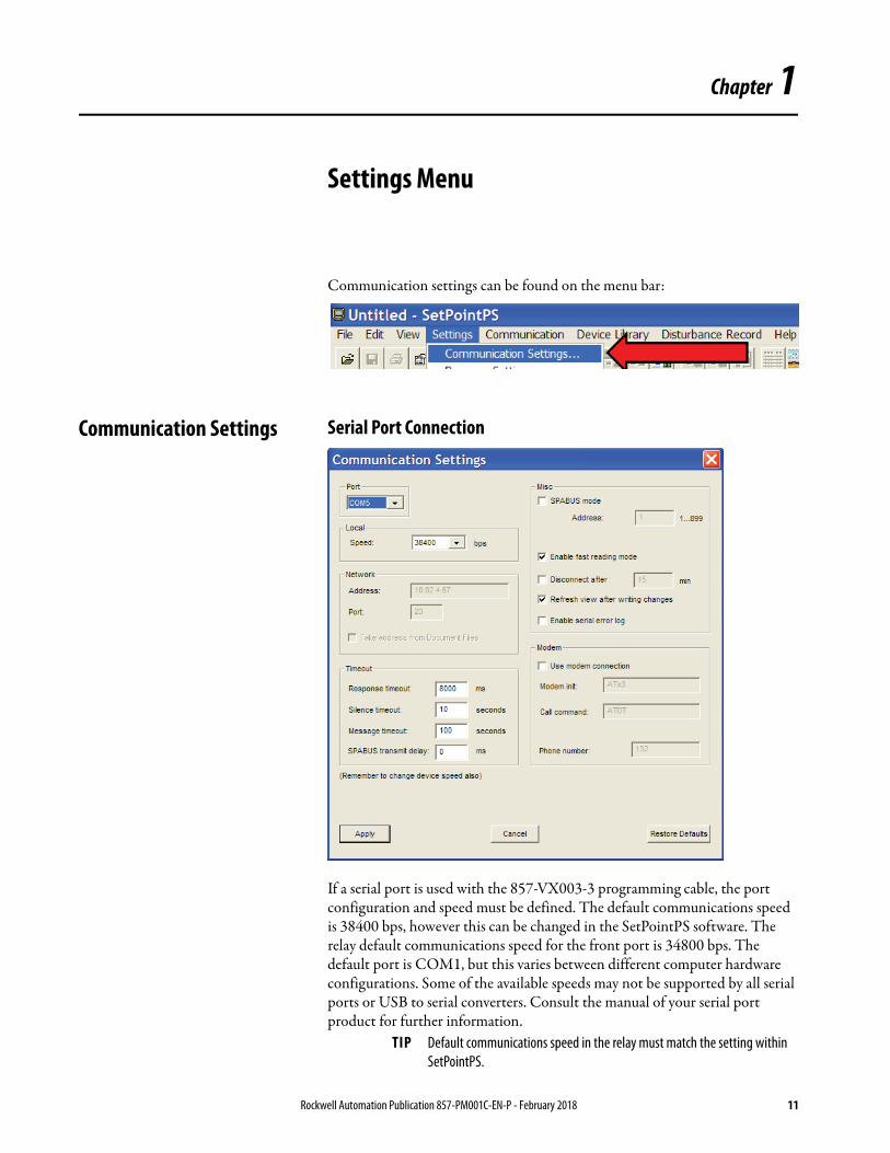
Communication settings can be found on the menu bar:
Communication Settings Serial Port Connection
If a serial port is used with the 857-VX003-3 programming cable, the port configuration and speed must be defined. The default communications speed is 38400 bps, however this can be changed in the SetPointPS software. The relay default communications speed for the front port is 34800 bps. The default port is COM1, but this varies between different computer hardware configurations. Some of the available speeds may not be supported by all serial ports or USB to serial converters. Consult the manual of your serial port product for further information.
TIP Default communications speed in the relay must match the setting within SetPointPS.
Rockwell Automation Publication 857-PM001C-EN-P - February 2018 11
Chapter 1 Settings Menu
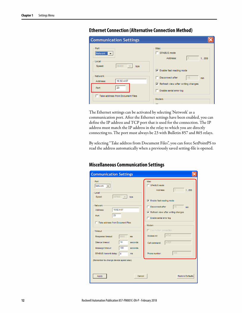
Ethernet Connection (Alternative Connection Method)
The Ethernet settings can be activated by selecting 'Network' as a communication port. After the Ethernet settings have been enabled, you can define the IP address and TCP port that is used for the connection. The IP address must match the IP address in the relay to which you are directly connecting to. The port must always be 23 with Bulletin 857 and 865 relays.
By selecting “Take address from Document Files”, you can force SetPointPS to read the address automatically when a previously saved setting-file is opened.
Miscellaneous Communication Settings
12 Rockwell Automation Publication 857-PM001C-EN-P - February 2018

Settings Menu Chapter 1
See 857 Protection System for Feeder and Motor Protection, Series A, user manual, publication 857-UM001, for details on configuring the EtherNet/IP communications interface. The network IP address must match the IP address configured in the device
Sometimes it is useful to adjust different communication timeout values. For example, the timeout values might need to be increased when using a slow and unreliable communications pathway.
Fast reading mode increases the speed of the communication, but this can be disabled if the communications pathway is unreliable.
Changing some of the parameters causes the relay to recalculate some other related parameters. By default, SetPointPS refreshes the view when changes have been made. This feature can be also disabled, if necessary.
Program Settings Program settings can be found on the menu bar:
Rockwell Automation Publication 857-PM001C-EN-P - February 2018 13

Chapter 1 Settings Menu
Initial Reading and Group Refresh Settings
These settings relate to how the SetPointPS software and the Bulletin 857 or Bulletin 865 relays interact. It is recommended to keep the default settings.
View Settings
Show parameters using boxes:• When enabled, SetPointPS draws borders around parameters that
belong together.• It is recommended to enable this setting.
Enable folder view:• When enabled, this feature provides configuration Tabs across the
display, organizing the setting functions in a more logic and organized manner. It is highly recommended that you enable this setting. An example of the Folder View display format is shown below.
PQ-diagram style:• This setting changes the axes of the PQ-diagram.
14 Rockwell Automation Publication 857-PM001C-EN-P - February 2018

Settings Menu Chapter 1
Log Files
The file path of the different kinds of logging states is enabled by checking the appropriate box. The file paths can be entered directly into the text boxes or selected by using the Browse buttons.
If the file does not exist, a new undefined file is created automatically. Log files are ASCII text so they can be opened using any text editor, for example, Windows Notepad.
Device Library
This section allows for specific indication of the location of the primary SetPointPS program (root directory) and an associated location where the software can save specific relay data (backup directory). The root directory and the backup directory must be mapped. Do not map the root directory to the file location where the SetPointPS executable file (setpointps.exe) resides.
The backup directory location is a file location where data from the relay can be stored temporarily. A backup directory must be mapped if any firmware updates to the relay are made. All database files within the relay are stored temporarily in this location and then recovered and reloaded back into the relay. Failure to map a backup directory can cause a firmware update to fail prematurely.
IMPORTANT The path and folder must already exist within your Windows directory tree or the log is not created. Double-check the file folders exist.
Events log Event logs are appended when events are read from the device.
Changes log Changes logs are updated every time that any parameter is changed in SetPointPS and saved/sent to the relay.
IMPORTANT The path and folder must already exist within your Windows directory tree or the log is not created. Double-check the file folders exist.
Rockwell Automation Publication 857-PM001C-EN-P - February 2018 15

Chapter 1 Settings Menu
If the file does not exist, a new undefined file is created automatically. Log files are ASCII text so they can be opened using any text editor, for example, Windows Notepad.
Default Passwords
It is possible to redefine the factory default passwords in SetPointPS. These passwords are automatically used with the corresponding access level when you do not manually provide a password. See Chapter 3 for additional details. If the factory default passwords have been changed in the relay, these passwords will no longer be valid.
Read/Write Settings
The write settings parameter controls when any changes you make are transferred to the relay. Check Write changes automatically after change (WAC) to transfer any change into the settings within the relay. The recommended condition is disabled to prevent accidental parameter changes within the relay.
Device Not Connected or WAC Disabled• Changed parameter values are displayed in a red font.
• New value must be transferred to the device manually, by pressing or using menu command: Communication/Write Changed Settings to Device.
• When the document is saved, any changes that are shown in red font are only be saved to the offline file. They are not transferred to the relay automatically. This makes it possible to make changes offline and to write the parameter changes to the relay later from the saved document.
16 Rockwell Automation Publication 857-PM001C-EN-P - February 2018

Settings Menu Chapter 1
Device Connected and WAC Enabled• Changed values are transferred to the device immediately and are
displayed in a black font.• Changed parameters are read back from the device after the transfer• It is recommended that the WAC feature is not enabled for the average
user. Changes are made automatically, which could cause adverse reactions in running protection situations.
ATTENTION: The WAC feature is for qualified personnel only. Unpredictable results can occur if the device is operating in a live protection and control environment with WAC enabled.
Rockwell Automation Publication 857-PM001C-EN-P - February 2018 17

Chapter 1 Settings Menu
Notes:
18 Rockwell Automation Publication 857-PM001C-EN-P - February 2018
Chapter 2
Communication Menu
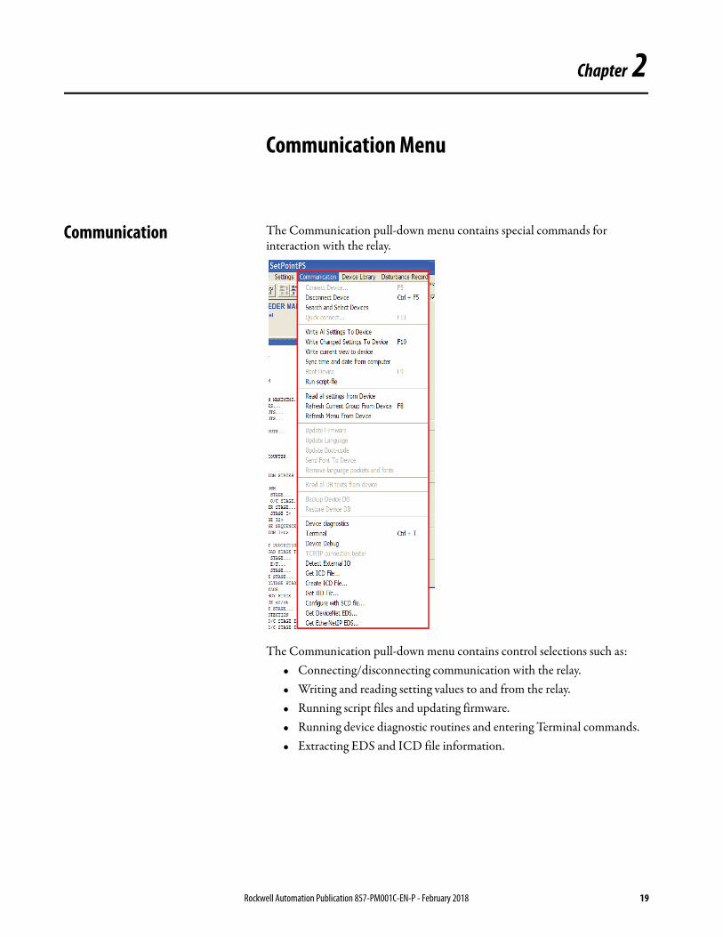
Communication The Communication pull-down menu contains special commands for interaction with the relay.
The Communication pull-down menu contains control selections such as:• Connecting/disconnecting communication with the relay.• Writing and reading setting values to and from the relay.• Running script files and updating firmware.• Running device diagnostic routines and entering Terminal commands.• Extracting EDS and ICD file information.
Rockwell Automation Publication 857-PM001C-EN-P - February 2018 19

Chapter 2 Communication Menu
Many of these commands are also using the control tabs on SetPointPS tool bar. SetPointPS toolbar commands are defined on page 26.
Communication Special Commands
Connect, Disconnect, and Quick Connect
The normal “Connect/Disconnect Device” buttons are available both in the Communication-menu and in the toolbar. Function keys also initiate these functions; F5 connects to the device downloading the relays settings and CTRL+F5 disconnects the relay from the software.
The Connect Device command causes SetPointPS to read ALL the available menus and parameters from the relay reads. Reading the full menu structure might take some time if using slower communication rates.
20 Rockwell Automation Publication 857-PM001C-EN-P - February 2018
Communication Menu Chapter 2
The menu has one additional command that can connect to the relay “Quick connect”. This command connects and reads only the menu structure and device info data. Push F11 on your keyboard to initiate the Quick connect command. The remaining parameters are read from the relay on demand only.
Search and Select Devices
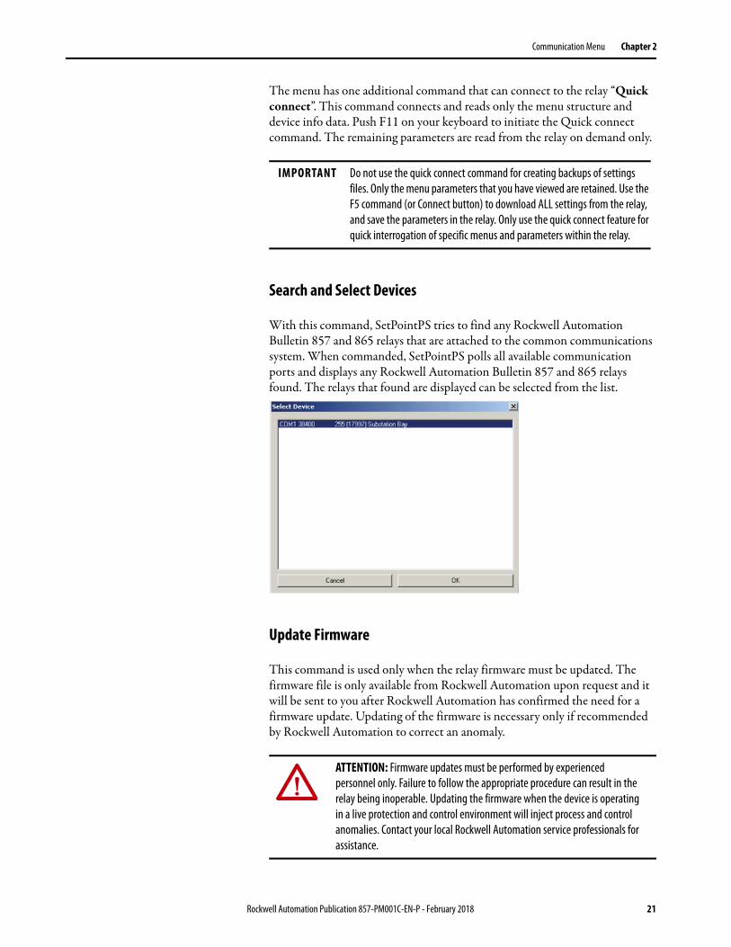
With this command, SetPointPS tries to find any Rockwell Automation Bulletin 857 and 865 relays that are attached to the common communications system. When commanded, SetPointPS polls all available communication ports and displays any Rockwell Automation Bulletin 857 and 865 relays found. The relays that found are displayed can be selected from the list.
Update Firmware
This command is used only when the relay firmware must be updated. The firmware file is only available from Rockwell Automation upon request and it will be sent to you after Rockwell Automation has confirmed the need for a firmware update. Updating of the firmware is necessary only if recommended by Rockwell Automation to correct an anomaly.
IMPORTANT Do not use the quick connect command for creating backups of settings files. Only the menu parameters that you have viewed are retained. Use the F5 command (or Connect button) to download ALL settings from the relay, and save the parameters in the relay. Only use the quick connect feature for quick interrogation of specific menus and parameters within the relay.
ATTENTION: Firmware updates must be performed by experienced personnel only. Failure to follow the appropriate procedure can result in the relay being inoperable. Updating the firmware when the device is operating in a live protection and control environment will inject process and control anomalies. Contact your local Rockwell Automation service professionals for assistance.
Rockwell Automation Publication 857-PM001C-EN-P - February 2018 21

Chapter 2 Communication Menu
Update Language
With this command, the relays language set can be updated to use other languages. The default language is English. Other languages files are available from Rockwell Automation.
1. Verify that you are using the latest SetPointPS program from the Rockwell Automation website.
2. Copy all given files to your hard disk to a place you can find them easily.
3. Connect the 857-VX003-3 cable between the PC and front port of the relay.
4. Start SetPointPS and select a communication port by selecting Settings Communication settings.
5. Select menu Communication/Update Language.
6. Choose Yes from the warning dialog.
7. Select the language file and click Open.
SetPointPS starts the update and the Serial Communication dialog is displayed. Uploading a language file takes about 5 minutes.
8. Do not disconnect the power supply from the relay. When the language update is complete, this will show in the final row of the update dialog.
9. Close the dialog window and SetPointPS.
IMPORTANT Language file updates are not supported using the Ethernet port.
22 Rockwell Automation Publication 857-PM001C-EN-P - February 2018

Communication Menu Chapter 2
10. Navigate to the LANGUAGE window. The window now shows the default language and the language which was uploaded to the relay.
11. Press INFO in the HMI.
12. Press ENTER and give the Configurator password (default 2).
Press ENTER again.
13. The currently active language is displayed with black background.
14. Select the desired language and press enter. The relay language changes to the new selection in 10…20 seconds.
Press CANCEL to return to the main display.
15. Verify that the language is changed in the relay.
16. Read a new SetPointPS setting-file from the relay using the computer and save the new settings for archiving. Do not use older setting files which were made using different languages.
Rockwell Automation Publication 857-PM001C-EN-P - February 2018 23

Chapter 2 Communication Menu
Exporting ICD, IID, SCD, and EDS Files
SetPointPS can be used for exporting a number of communication files, which is required for interfacing the relay with other systems. This functionality is found in the Communication menu of SetPointPS.
Additional Relay Configuration Commands
These commands are not used by the average relay user. These commands are only needed for special troubleshooting situations and their usage shall be by a Rockwell Automation customer support engineer, when required.
Get ICD File Reads an IEC 61850 IED capability description file from the connected relay (unconfigured IEC 61850 server device description).
Create ICD File Builds an IEC 61850 IED capability description file from SetPointPS configuration data (offline, without connecting to the relay).
Get IID File Reads an IEC 61850 instantiated IED description file / configured IED description file from the connected relay (configured IEC 61850 server device description).
Configure with SCD file Configures the IEC 61850 interface of the relay with provided System Configuration Description file.
Get DeviceNet EDS DeviceNet is not supported in this product line.
Get EtherNetIP EDS Reads the EtherNet/IP slave electronic data sheet file from the connected relay.
Run Script File. Update Boot Code and Restore Device DB
These selections are needed only in special cases. The procedure is similar to the firmware and language updates and the usage is advised by Rockwell Automation support when necessary.
Read All DB Texts from device
With this command SetPointPS reads the database of the relay into a text file. This command is used for creating language files for the relay.
Terminal This command opens a terminal window that is used to interface with the relay by using the Get/Set-protocol. The usage of the terminal method is only advised by Rockwell Automation support when necessary.
24 Rockwell Automation Publication 857-PM001C-EN-P - February 2018

Chapter 3
Relay Configuration Window
Main Window
Views
The main window of SetPointPS is divided into six parts.
A Menu Bar Contains various settings and communication menus. B Toolbar Provides shortcuts to tools used for interfacing with the relay. Toolbar buttons are
described later in this manual.C Caption View Shows information about the relay that is being configured. The contents of these
fields can be defined by you. D Group List List of available setting parameter groups. The desired setting group must be selected
to access the setting parameters. E Group View The device configurations are made in this view. The different parameters are available
after selecting a group from the group list. Right mouse button can be used to scroll this view.
F Status Bar Displays the current state of SetPointPS and valid the valid range when parameters are being modified.
Rockwell Automation Publication 857-PM001C-EN-P - February 2018 25
Chapter 3 Relay Configuration Window
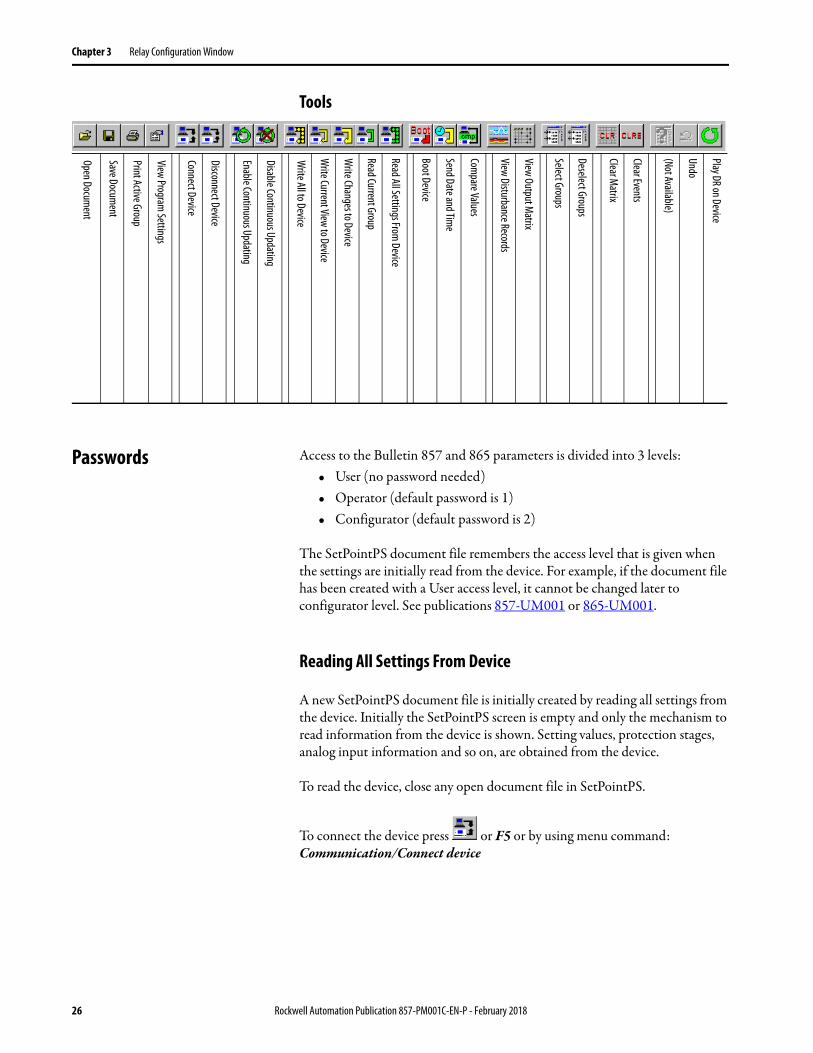
Tools
Passwords Access to the Bulletin 857 and 865 parameters is divided into 3 levels: • User (no password needed)• Operator (default password is 1)• Configurator (default password is 2)
The SetPointPS document file remembers the access level that is given when the settings are initially read from the device. For example, if the document file has been created with a User access level, it cannot be changed later to configurator level. See publications 857-UM001 or 865-UM001.
Reading All Settings From Device
A new SetPointPS document file is initially created by reading all settings from the device. Initially the SetPointPS screen is empty and only the mechanism to read information from the device is shown. Setting values, protection stages, analog input information and so on, are obtained from the device.
To read the device, close any open document file in SetPointPS.
To connect the device press or F5 or by using menu command: Communication/Connect device
Open Document
Save Document
Print Active Group
View Program Settings
Connect Device
Disconnect Device
Enable Continuous Updating
Disable Continuous Updating
Write All to Device
Write Current View to Device
Write Changes to Device
Read Current Group
Read All Settings From Device
Boot Device
Send Date and Time
Compare Values
View Disturbance Records
View Output Matrix
Select Groups
Deselect Groups
Clear Matrix
Clear Events
(Not Available)
Undo
Play DR on Device
26 Rockwell Automation Publication 857-PM001C-EN-P - February 2018

Relay Configuration Window Chapter 3
If the communication between SetPointPS and the device is successfully established, SetPointPS starts to upload the available menu parameter groups and displays this dialog.
After a few moments, SetPointPS asks for the access level. If the password field is left empty, SetPointPS tries to use a default password.
All Rockwell Automation Bulletin 857 and 865 products use the following default passwords:
• Configurator: 2 (can be entered as 0002)• Operator: 1 (can be entered as 0001)• User: no password is required
Rockwell Automation Publication 857-PM001C-EN-P - February 2018 27

Chapter 3 Relay Configuration Window
After pressing the OK button, SetPointPS starts to upload information about the settings and special features that are available in the relay. Depending on the device and communication speed, this will between 2…3 minutes. The upload can be stopped by choosing the Stop operation button on the lower left corner of the communication dialog.
Save a SetPointPS File
Press to save a SetPointPS file to a disk, or use menu command: File/Save. Save as saves the file to a specific location.
Load a Document
Press to open a SetPointPS document file, or use menu command: File/Open.
Download to Device (Copy Settings Between Devices)
Open the appropriate document file and press to connect to a device, or use menu command: Communication/Connect Device.
The whole SetPointPS document can be transmitted to the device by using menu command: Communication/Write all settings to device.
The destination device can be the same one that was used when the file was created, or any other device of the same type with a similar firmware level. This makes it easy to configure several devices with the same settings.
IMPORTANT The settings files are firmware version dependent. You can upload a settings file used in a relay with an older version of firmware to a relay that has a newer firmware version, but not vice versa.
28 Rockwell Automation Publication 857-PM001C-EN-P - February 2018

Relay Configuration Window Chapter 3
1. Open a SetPointPS document or create a new one by reading from device. The following dialog opens automatically.
2. Select the access level for the opened document from the SetPointPS shown dialog.
3. Change the settings, if necessary.
4. Save the document.
5. Connect to the device and transmit the settings to the device by using menu command: Communication/Write all settings to device or click
the Write All Settings on the tool bar.
6. Press to disconnect the device, or use menu command: Communication/Disconnect Device.
7. Connect the serial cable to the next device, or if you are using Ethernet, change the IP address in via the Protocol Configuration tab in the Group List.
8. Change the device name and location on Device Info setting group.
This step is optional but it is a recommended best practice to give individual names to different devices.
9. Save the document with a new name by using menu command: File/Save as. This step is not needed if only one document is enough for all devices.
10. Connect to the new device using menu command: Communication/Disconnect Device. SetPointPS gives a notice that the serial number differs from the currently connected device. Click OK and write all settings into the relay.
11. Return to item 6 until all devices have been configured.
IMPORTANT The specifics that are related to each connected load (full load current, CT ratios, and so forth) must still be modified.
Rockwell Automation Publication 857-PM001C-EN-P - February 2018 29

Chapter 3 Relay Configuration Window
Notes:
30 Rockwell Automation Publication 857-PM001C-EN-P - February 2018
Chapter 4
Setting Groups
The device settings are divided into several groups. There are different groups for every protection stage, communication protocol, analog output and so on. Most of the setting groups are of the basic type, which only contains a list of parameters. There are also some special groups like Matrix and PQ-diagram.
This chapter gives a short description of some of the different kinds of setting groups.
Device Information
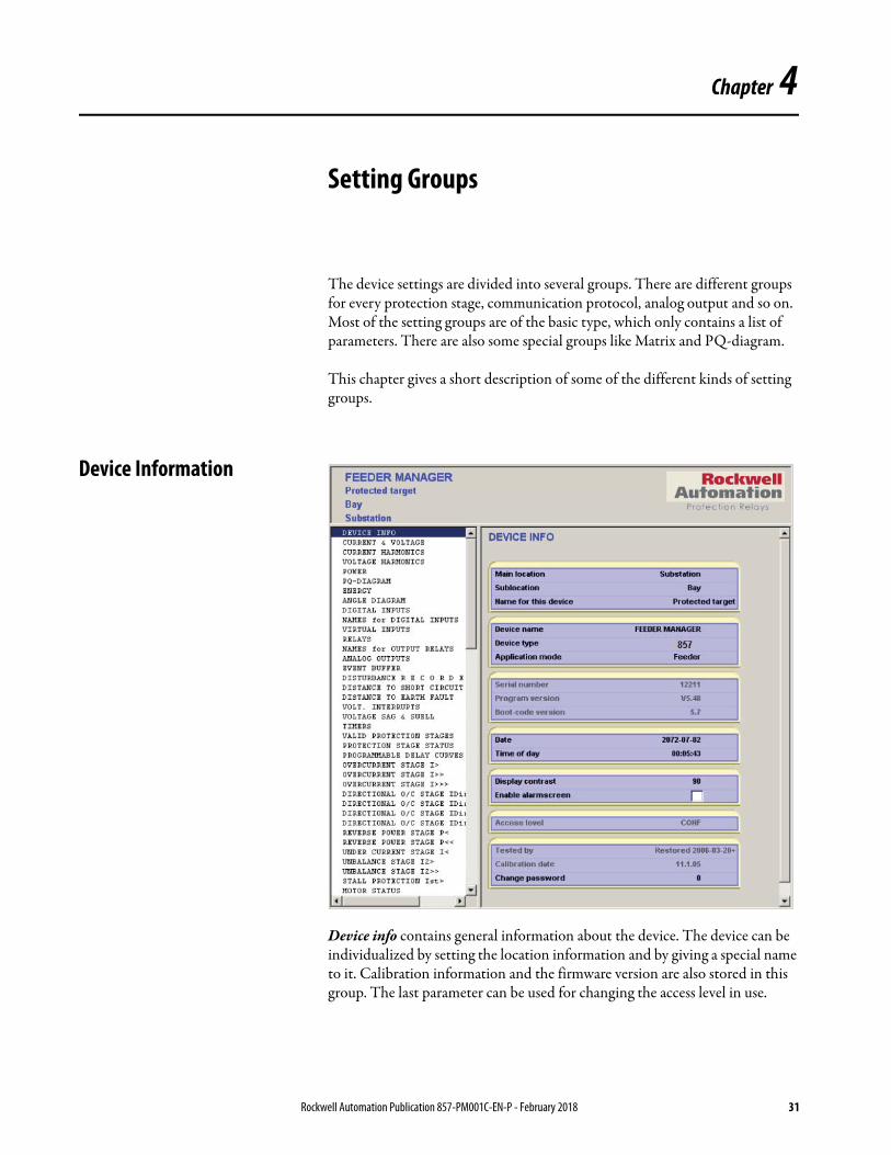
Device info contains general information about the device. The device can be individualized by setting the location information and by giving a special name to it. Calibration information and the firmware version are also stored in this group. The last parameter can be used for changing the access level in use.
Rockwell Automation Publication 857-PM001C-EN-P - February 2018 31

Chapter 4 Setting Groups
Basic Groups Protection Stage Groups
A protection stage group consists of four parts.
Stage Enabling • The protection stage can be enabled or disabled by checking or clearing the selection box.
• Configurator access level is needed for changing the parameter.
Stage Status • Shows the state of the input signals that are used by the stage.• Shows the present state of the stage, estimated time to trip and also start (alarm) and
trip counters.
Stage Settings • Contains limit and delay settings for the stage. Provides for selection of setting group (up to four) on some protection stages
• Configurator access level is needed for changing the stage settings.
Fault Log • Shows eight latest events of the stage.• The fault log is in descending order; the latest event is on the first row.
32 Rockwell Automation Publication 857-PM001C-EN-P - February 2018
Setting Groups Chapter 4
Phase Angle Diagrams
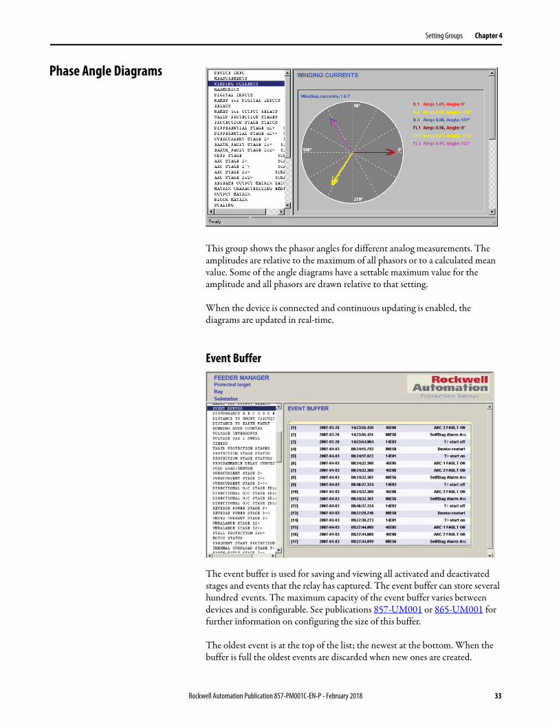
This group shows the phasor angles for different analog measurements. The amplitudes are relative to the maximum of all phasors or to a calculated mean value. Some of the angle diagrams have a settable maximum value for the amplitude and all phasors are drawn relative to that setting.
When the device is connected and continuous updating is enabled, the diagrams are updated in real-time.
Event Buffer
The event buffer is used for saving and viewing all activated and deactivated stages and events that the relay has captured. The event buffer can store several hundred events. The maximum capacity of the event buffer varies between devices and is configurable. See publications 857-UM001 or 865-UM001 for further information on configuring the size of this buffer.
The oldest event is at the top of the list; the newest at the bottom. When the buffer is full the oldest events are discarded when new ones are created.
Rockwell Automation Publication 857-PM001C-EN-P - February 2018 33

Chapter 4 Setting Groups
An event carries the following information:• full-time stamp• event code• short description
Local Panel Display
With the ‘Local panel display’ you can remotely control the relay and input front panel commands just as they would by using the physical HMI on the relay.
Click any of the operator push buttons to mimic the physical depression of the push buttons on the face of the relay.
34 Rockwell Automation Publication 857-PM001C-EN-P - February 2018

Setting Groups Chapter 4
Matrix Groups Output Matrix
There are several different settings groups under the Matrix command, including Output Matrix, Block Matrix, External Digital Output Matrix, and Object Block Matrix.
By using the Output Matrix, the output signals of the various protection stages, digital inputs, logic outputs, and other internal signals can be electronically connected to the output relays, front panel indicators, virtual outputs, and the Disturbance Recorder.
The Alarm and Trip status indicators on the front panel and the three general-purpose status indicators ("A", "B", and "C") are available for customer-specific indications. The output matrix can also be configured to trigger the disturbance recorder (DR) and four virtual outputs.
An output relay or status indicator can be configured as either being latched or non-latched. A non-latched relay follows the condition of the controlling signal. A latched relay remains activated even if the controlling signal has changed state a second time.
The output matrix can be viewed by selecting it from the group list or by
pressing . This matrix has two kinds of connections:
Matrix connection without latch• When the protection element is activated, the output tied to this signal
is activated.• When the protection element is released, the output tied to this signal is
released.
Rockwell Automation Publication 857-PM001C-EN-P - February 2018 35

Chapter 4 Setting Groups
Latched matrix connection• When the protection element signal is activated, the output is activated• When the protection element is released, the output remains active until
cleared manually. Latched outputs can be cleared from the “Release Output Matrix Latches” settings group and from the HMI of the relay by pushing Enter on the front of the relay.
• When a connection is latched, it provides a lockout protection feature (IEEE Device Number 86).
Block Matrix
The Block Matrix group inhibits protection stages from operating by using input signals from other protection stages, digital inputs, and arc sensors. Input signals are on the left side and protection stages to be blocked are displayed on the top.
36 Rockwell Automation Publication 857-PM001C-EN-P - February 2018

Setting Groups Chapter 4
Placing a Matrix Connection
Placing a connection is done by clicking the left mouse button at a crossing point of a signal and output line.
Press to clear the entire matrix.
Disturbance Recorder (DR)
All Allen-Bradley® 857 and 865 relays include a built-in disturbance recorder for evaluating all measured signals, including currents, voltages, and the status information of all of digital inputs (DI) and digital outputs (DO). The digital inputs include arc protection signals S1, S2, BI, and BO, if the optional arc protection is configured.
At maximum there can be 12 recordings, and the maximum selection of channels in one recording is also 12 (limited in waveform recording). The digital inputs reserve one channel (includes all inputs). Also the digital outputs reserve one channel (includes all outputs). If digital inputs and outputs are recorded, there are 10 channels that are left for analog waveforms.
Rockwell Automation Publication 857-PM001C-EN-P - February 2018 37

Chapter 4 Setting Groups
This subject is covered in detail in Chapter 5.
This group is used for configuring the disturbance recorder. See Changing the Disturbance Recorder Settings on page 65 for a more detailed description about the settings of disturbance recorder.
Making Relay Settings Change Values
A device parameter can have four different access types:• Read (for example, measurements)• User Write (for example, display brightness)• Operator Write (for example, I> current limit)• Configurator Write (for example, I> stage enable)
SetPointPS shows parameters in three colors depending on present access level, the access type of the parameter and if the value has been changed or not.
A parameter has one of the following colors:
Red• Parameter value has been changed in the SetPointPS software but not
downloaded to the device
Black• Parameter value in SetPointPS matches the setting in the relay
Dimmed (Greyed Out)• No write access• Parameter is either read-only or the present access level is not high
enough
38 Rockwell Automation Publication 857-PM001C-EN-P - February 2018

Setting Groups Chapter 4
Change Parameter Values Click the left mouse button on the value that must be changed. When the text input box appears, use the keyboard to type a new value and press enter. The valid setting range is displayed at the bottom left corner of the main window.
If the typed value is out of permitted the range, SetPointPS will give a warning after transmitting changes to the device and the illegal value is replaced by current device value.
Some of the parameters have a fixed set of values that can be chosen from a pull-down menu.
Click the value and choose the correct value.
Automatic Restart Requested (Boot Pending)
Some parameter changes require the relay to restart to become valid. When such a parameter has been changed and transferred to the device, the following dialog appears:
Boot Now• SetPointPS sends a restart command to the device immediately.
Rockwell Automation Publication 857-PM001C-EN-P - February 2018 39

Chapter 4 Setting Groups
Boot Later• The dialog box closes without restarting the device.• Latest changes that need restarting are not taken into account.
• The device can be restarted later by pressing or F9, by cycling control power, or by using menu command: Communication/Boot Device.
Communication Protocol Settings
Change Protocols
Remote port, Local port, and Extension port protocols are changed in the Protocol Configuration group. This group also contains message and error counters for the selected protocol and ports. See publications 857-UM001 and 865-UM001 for a description of protocol usage. Available protocols are EtherNet/IP, ModBus, ModBus TCP/IP, SPA-Bus, PROFIBUS, IEC-103, External I/O, DNP3, ANSI85 and IEC-61850.
40 Rockwell Automation Publication 857-PM001C-EN-P - February 2018

Setting Groups Chapter 4
SPA-Bus Settings
SPA-Bus protocol has following settings available:
SPA-Bus Address• Setting range 1…899.
SPA-Bus bit Rate• The available bit rates are 1200, 2400, 4800, 9600, 19200.
Modbus Settings
The first three settings in the Modbus MAIN CONFIGURATION group are used in both Modbus Master and Modbus Slave protocols. In Modbus master mode, the slave address is the destination address and in slave mode, the slave address is the device address. Setting range for bit rate is 1200…19200 bps.
Rockwell Automation Publication 857-PM001C-EN-P - February 2018 41
Chapter 4 Setting Groups
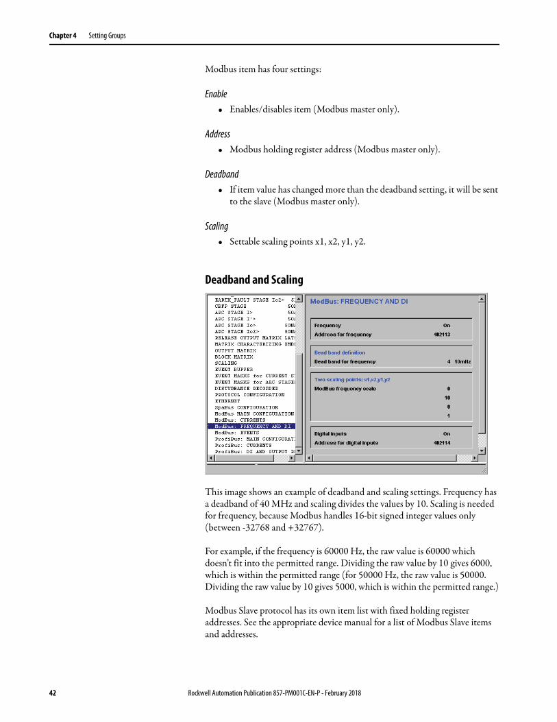
Modbus item has four settings:
Enable• Enables/disables item (Modbus master only).
Address• Modbus holding register address (Modbus master only).
Deadband• If item value has changed more than the deadband setting, it will be sent
to the slave (Modbus master only).
Scaling• Settable scaling points x1, x2, y1, y2.
Deadband and Scaling
This image shows an example of deadband and scaling settings. Frequency has a deadband of 40 MHz and scaling divides the values by 10. Scaling is needed for frequency, because Modbus handles 16-bit signed integer values only (between -32768 and +32767).
For example, if the frequency is 60000 Hz, the raw value is 60000 which doesn’t fit into the permitted range. Dividing the raw value by 10 gives 6000, which is within the permitted range (for 50000 Hz, the raw value is 50000. Dividing the raw value by 10 gives 5000, which is within the permitted range.)
Modbus Slave protocol has its own item list with fixed holding register addresses. See the appropriate device manual for a list of Modbus Slave items and addresses.
42 Rockwell Automation Publication 857-PM001C-EN-P - February 2018

Setting Groups Chapter 4
PROFIBUS Settings
PROFIBUS mode can be selected in the PROFIBUS: MAIN CONFIGURATION group.
PROFIBUS item has three settings:
On/Off• Enables/disables item• Continuous mode only
Offset• Address for item• Continuous mode only
Scaling• Settable scaling points x1, x2, y1, y2• Works the same way as Modbus scaling.
See Modbus Settings on page 41.
In request mode, all items are enabled and they have fixed offsets. See the device manual for a list of request mode items.
Rockwell Automation Publication 857-PM001C-EN-P - February 2018 43

Chapter 4 Setting Groups
IEC 60870-5-103 Settings Main Configuration
IEC-103 Slave Number• setting range 1…254 (255 is reserved for broadcasts)• this is used as link layer address and as common address of ASDU in
application layer
IEC-103 Bit Rate• 9600 bps or 19200 bps
Meas sending interval
This setting restricts measurement sending. The next measurement is not sent until the time interval has elapsed since last sending. During this time, the device responses to a class-2 poll by sending a ‘data not available’ message.
ASDU 6 Response Time Mode
This setting defines which time stamp is sent in response to a time synchronizing message. The following modes are available:
SYNC Device sends back the same time stamp that the master sent in the synchronizing message.
SYNC + PROC Device adds its internal processing time to the time stamp in the synchronizing message and sends the sum in the response message.
MSG Device sends back its internal time stamp of the first received bit of the synchronizing message from master. This mode can be useful because subtracting the time stamp found in the response message from the time stamp that the master sent in the sync message gives the time difference between the master and the device just before the new sync became valid.
MSG + PROC Otherwise the same as MSG but internal processing time is added to the time stamp
44 Rockwell Automation Publication 857-PM001C-EN-P - February 2018
Setting Groups Chapter 4
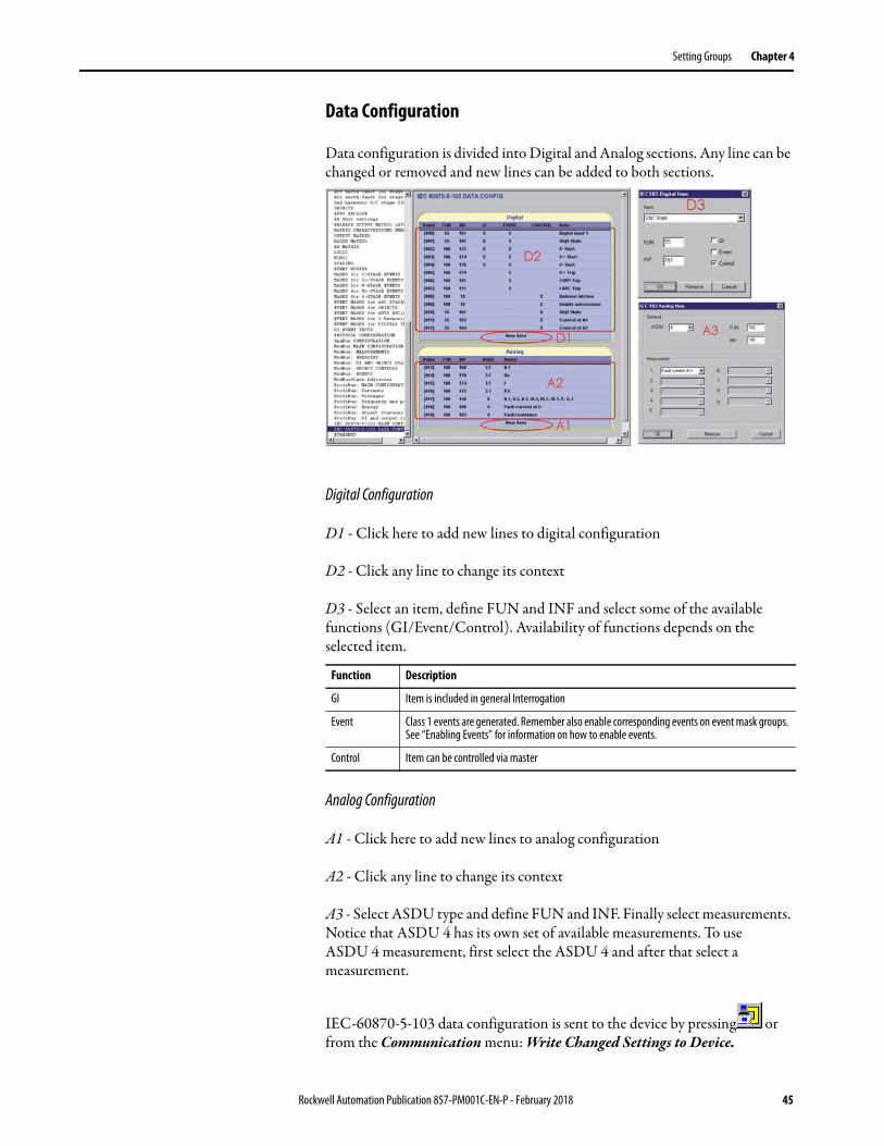
Data Configuration
Data configuration is divided into Digital and Analog sections. Any line can be changed or removed and new lines can be added to both sections.
Digital Configuration
D1 - Click here to add new lines to digital configuration
D2 - Click any line to change its context
D3 - Select an item, define FUN and INF and select some of the available functions (GI/Event/Control). Availability of functions depends on the selected item.
Analog Configuration
A1 - Click here to add new lines to analog configuration
A2 - Click any line to change its context
A3 - Select ASDU type and define FUN and INF. Finally select measurements. Notice that ASDU 4 has its own set of available measurements. To use ASDU 4 measurement, first select the ASDU 4 and after that select a measurement.
IEC-60870-5-103 data configuration is sent to the device by pressing or from the Communication menu: Write Changed Settings to Device.
Function Description
GI Item is included in general Interrogation
Event Class 1 events are generated. Remember also enable corresponding events on event mask groups. See “Enabling Events” for information on how to enable events.
Control Item can be controlled via master
Rockwell Automation Publication 857-PM001C-EN-P - February 2018 45
Chapter 4 Setting Groups
Communications Protocol for 857-RAA and 857-RAD
The 857-RAA and 857-RAD remote RTD Scanner options require specific protocol configurations. See publication 857-UM002 for complete details on the appropriate protocol settings.
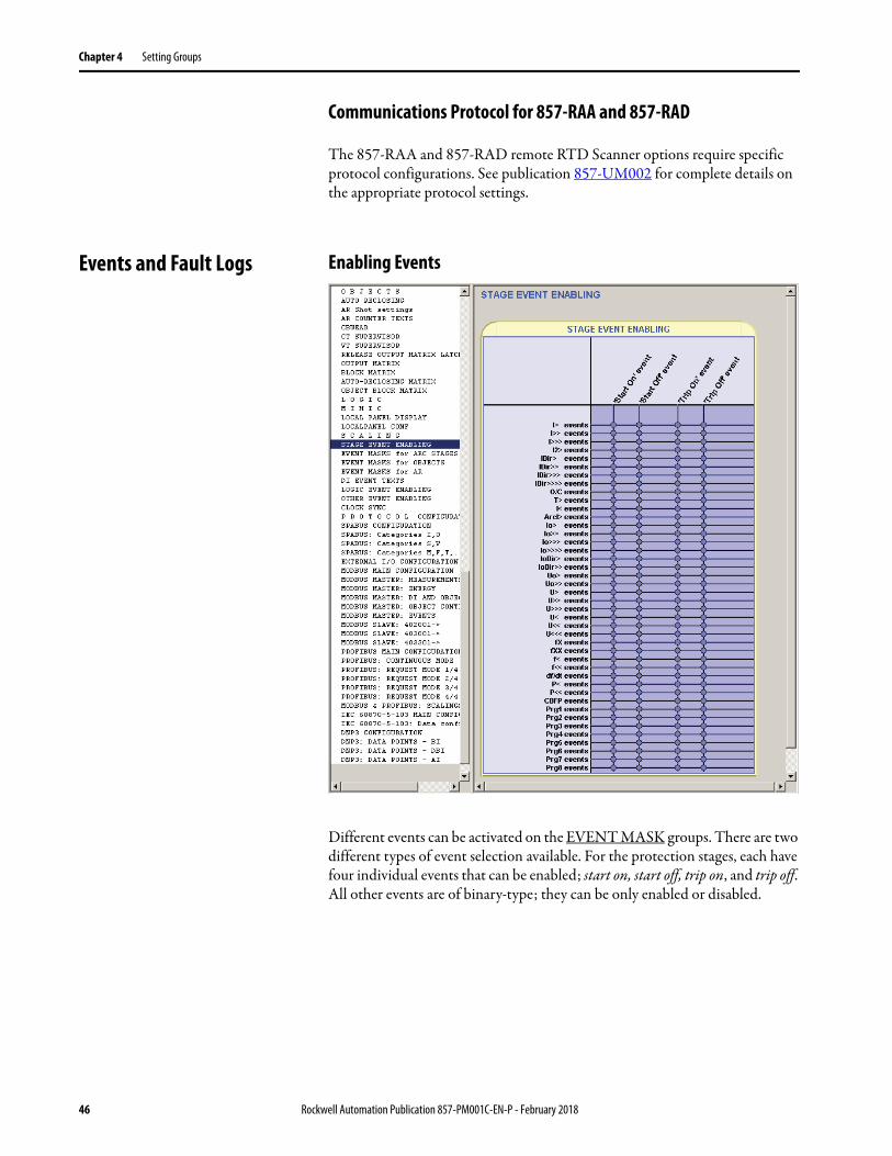
Events and Fault Logs Enabling Events
Different events can be activated on the EVENT MASK groups. There are two different types of event selection available. For the protection stages, each have four individual events that can be enabled; start on, start off, trip on, and trip off. All other events are of binary-type; they can be only enabled or disabled.
46 Rockwell Automation Publication 857-PM001C-EN-P - February 2018

Setting Groups Chapter 4
Reading From Device
Before events can be read from the device, the EVENT BUFFER group must be selected from the group list.
Events are read from the device by pressing . If Continuous updating is enabled, events are updated automatically when the EVENT BUFFER group
is selected. Continuous updating can be enabled by pressing and disabled
by pressing .
IMPORTANT SetPointPS can only read new events (which have not been read by SetPointPS earlier) from the device. Once the events have been transferred from the device, it’s not possible to read those particular events again and thus it is important to save the SetPointPS setting file.
Rockwell Automation Publication 857-PM001C-EN-P - February 2018 47
Chapter 4 Setting Groups
Saving to Disk
Events and fault logs are saved with the SetPointPS file extension (.vf2).
Events can be saved into a log file, which is updated automatically after reading events from the device. Event logs are plain ASCII files thus they can be opened with any text editor like Windows Notepad. See page 13 for information on how to enable event logging.
Clearing Events
SetPointPS event buffer can be cleared by pressing .
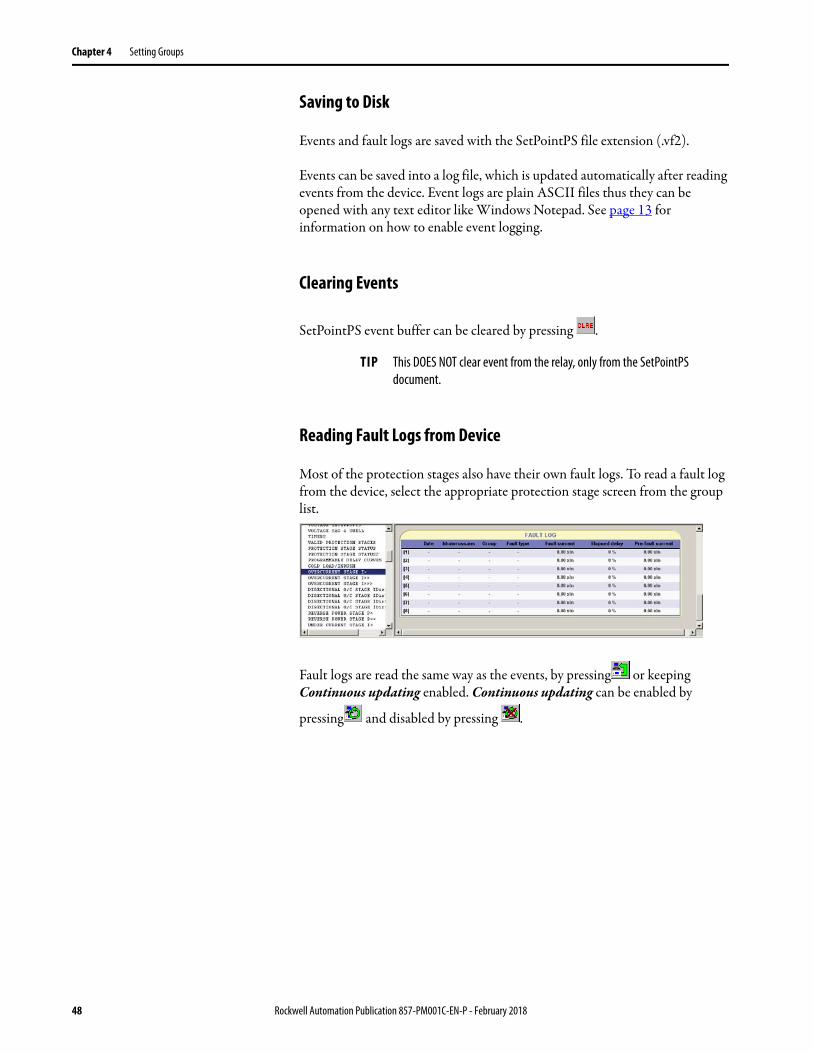
Reading Fault Logs from Device
Most of the protection stages also have their own fault logs. To read a fault log from the device, select the appropriate protection stage screen from the group list.
Fault logs are read the same way as the events, by pressing or keeping Continuous updating enabled. Continuous updating can be enabled by
pressing and disabled by pressing .
TIP This DOES NOT clear event from the relay, only from the SetPointPS document.
48 Rockwell Automation Publication 857-PM001C-EN-P - February 2018

Setting Groups Chapter 4
Mimic Editor The Mimic editor group is used for creating and editing mimic display of the relay local panel.
To show the mimic editor, select MIMIC group from the group list.
Clearing Mimic Display
1. Select the deleting tool.
2. Click left mouse button over any empty space. Confirmation window appears.
3. Press OK to clear the display.
Rockwell Automation Publication 857-PM001C-EN-P - February 2018 49

Chapter 4 Setting Groups
Selecting Continuously Displayed Measurands and Status Indicators
Maximum of 6 analog measurements or status indicators to be continuously displayed can be selected on the right side of the display.
Follow these steps to select your desired measurands and status indicators.
1. Select the General tab from the main SetPointPS screen.
2. Select MIMIC from the left-side pane.
3. Click on the desired value to access the pulldown menu.
4. Click the measurand for status indicator to select.
50 Rockwell Automation Publication 857-PM001C-EN-P - February 2018

Setting Groups Chapter 4
Working with Virtual Buttons
Depending on the device model, the local panel mimic display can contain some virtual status indicators.
• Auto-reclose ON/OFF• Remote/Local switch • Virtual outputs
Follow these steps to show/hide the virtual status buttons.
1. Select the desired virtual status button on the bottom row.
2. To move the value around the screen, click, hold, and drag the value.
3. Click the virtual status button to hide the value.
This may be necessary based on the selection of other screen display options and their default locations.
The status of the four virtual inputs can be monitored on the front display as well. The status for each individual virtual input can be independently selected and displayed by clicking on the appropriate location.
Delete Button
Virtual Status Buttons
Rockwell Automation Publication 857-PM001C-EN-P - February 2018 51

Chapter 4 Setting Groups
Location Information
Location information is displayed in the top of the display. This is the same setting as Sublocation on Device Info group and is also displayed on the caption view of SetPointPS.
To change the sublocation, follow these steps.
1. Click the Sublocation button.
2. Click on SubLoc.
3. Enter the new location information and press ENTER.
Adding Lines
1. Select one of the line characters.
2. Press and hold the left mouse button over empty space.
Short piece of line appears at mouse cursor.
3. Move the piece to desired location.
4. Release the left mouse button.
5. Continue from step 2 until the line is complete.
52 Rockwell Automation Publication 857-PM001C-EN-P - February 2018

Setting Groups Chapter 4
Adding Objects
1. Select object type from the palette.
2. Press and hold left mouse button over empty space. New object appears at mouse cursor.
3. Move the object to correct place.
4. Release the left mouse button.
5. Select correct internal object numbers by clicking the left mouse button over active parts of the object. Clicking alternates unused object numbers. Use numbers 1 and 2 for objects that are controlled by the relay. More objects can be available for these purposes, depending on the relay software version. Check the Objects group for more information.
6. Make object settings in Objects group (if not done yet).
Relationship between object numbers in the Mimic group and the object settings in Objects group.
Rockwell Automation Publication 857-PM001C-EN-P - February 2018 53

Chapter 4 Setting Groups
Adding, Deleting, and Moving of Text Objects
Adding Text
1. Select the text tool (‘A’).
2. Press and hold left mouse button over empty space. New text object appears at mouse cursor.
3. Move text object to correct place.
4. Release the left mouse button and the editing window displays.
5. Type text and press OK.
Editing Text
1. Move mouse over a text object. The text becomes green.
2. Click left mouse button to show the editing dialog.
3. Type new text and press OK.
Deleting Objects, Text and Lines
54 Rockwell Automation Publication 857-PM001C-EN-P - February 2018

Setting Groups Chapter 4
1. Select the deleting tool (an empty box).
2. Move mouse over an object you want to delete. Object becomes red.
3. To delete the object, click left mouse button .
Sending to Device
MIMIC display configuration is sent to the device by pressing or selecting from the Communication menu: Write Changed Settings to Device
Logic Editor Fundamentals Adding the First Function
If the logic display is empty, to add the first function:
1. Click left mouse button anywhere on the display. Request window is displayed (1).
2. Press OK. An AND logic gate without inputs and outputs appears on the screen.
If an AND logic gate is not the type of function wanted, see Logic Function Properties on page 56 for information on how to change function types.
Rockwell Automation Publication 857-PM001C-EN-P - February 2018 55

Chapter 4 Setting Groups
Logic Function Properties
To edit properties of a logic function:
1. Click a function.
2. Click Edit Properties..
Type• Use this setting for changing the function type.
Count Setting• This is active only for Counter (CT)-function.• Defines how many rising edges must be detected in inputs before the
output is activated.
TON - (Time On)• Defines how long it takes to activate the output.
TOF - (Time Off )• Defines how long it takes to deactivate the output.
Output Setting - Inverted• This setting can be used for inverting the output signal.
56 Rockwell Automation Publication 857-PM001C-EN-P - February 2018

Setting Groups Chapter 4
Adding and Selecting of Input Signals
Only the left-most functions can take input from signals. Inputs of other functions are outputs from functions on their left side.
1. Click the input line of a function. Some functions can have several input groups. For example, ANDINV has direct inputs and inverted inputs. With those functions click the specific group to change the inputs.
2. To add new signals: select input signals from ‘Input signals available’ list and press the Add button.
3. To remove signals: select input signals from ‘Selected input signals’ list and press the Remove button.
4. To accept the changes, press OK.
Connections Between Functions
Add a New Connection
1. Press and hold the left mouse button over function output that is going to be connected to an input of another function.
2. Move the mouse near function input and release the left mouse button.
Several functions can be connected to the same destination function. SetPointPS adds new input pins for the destination function as necessary.
IMPORTANT Only connections between consecutive functions are valid and permitted.
Rockwell Automation Publication 857-PM001C-EN-P - February 2018 57
Chapter 4 Setting Groups
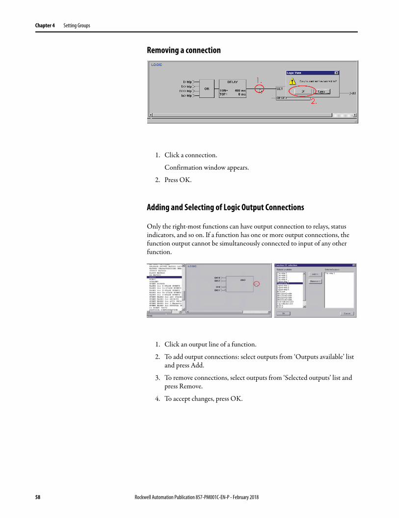
Removing a connection
1. Click a connection.
Confirmation window appears.
2. Press OK.
Adding and Selecting of Logic Output Connections
Only the right-most functions can have output connection to relays, status indicators, and so on. If a function has one or more output connections, the function output cannot be simultaneously connected to input of any other function.
1. Click an output line of a function.
2. To add output connections: select outputs from ‘Outputs available’ list and press Add.
3. To remove connections, select outputs from ‘Selected outputs’ list and press Remove.
4. To accept changes, press OK.
58 Rockwell Automation Publication 857-PM001C-EN-P - February 2018

Setting Groups Chapter 4
Deleting Functions
1. Click a function.
2. Press the Delete button.
Sending Revised Logic Configurations to a Device
The logic changes must be downloaded to the device before they become
active. Logic configurations are sent to the device by pressing or selecting from the Communication menu: Write Changed Settings to Device. This forces the relay to restart.
Other Functions Sending Time and Date to Device
SetPointPS can read time and date from the PC to synchronize the device.
Time and date is transferred by pressing or using menu command:
Transfer can be confirmed by selecting Device Info from the group list and
then pressing . Now the device time and date is the same as PCs.
Rockwell Automation Publication 857-PM001C-EN-P - February 2018 59

Chapter 4 Setting Groups
Comparing Settings between SetPointPS and a Relay
SetPointPS can compare all parameter values between a SetPointPS document
and the connected device. Comparing starts by pressing and then the following dialog is displayed:
After all settings have been compared, a new group will be added to the group list and set visible. This group shows the comparison result of the differences.
The results of the comparison are also saved with the SetPointPS document.
60 Rockwell Automation Publication 857-PM001C-EN-P - February 2018
Setting Groups Chapter 4
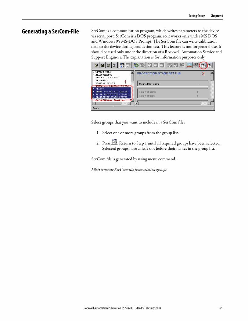
Generating a SerCom-File SerCom is a communication program, which writes parameters to the device via serial port. SerCom is a DOS program, so it works only under MS DOS and Windows 95 MS-DOS Prompt. The SerCom file can write calibration data to the device during production test. This feature is not for general use. It should be used only under the direction of a Rockwell Automation Service and Support Engineer. The explanation is for information purposes only.
Select groups that you want to include in a SerCom file:
1. Select one or more groups from the group list.
2. Press . Return to Step 1 until all required groups have been selected. Selected groups have a little dot before their names in the group list.
SerCom file is generated by using menu command:
File/Generate SerCom-file from selected groups
Rockwell Automation Publication 857-PM001C-EN-P - February 2018 61

Chapter 4 Setting Groups
62 Rockwell Automation Publication 857-PM001C-EN-P - February 2018

Chapter 5
Disturbance Record Evaluator
Main Window All Allen-Bradley 857 and 865 relays include a built-in Disturbance Recorder (DR) for evaluating all measured signals, including currents, voltages, and the status information of the digital inputs (DI) and digital outputs (DO). The digital inputs include arc protection signals S1, S2, BI, and BO, if the optional arc protection is configured.
There can be a maximum of 12 recordings, and the maximum selection of channels in one recording is also 12 (limited in waveform recording). The digital inputs reserve one channel (includes all inputs). Also the digital outputs reserve one channel (includes all outputs). If digital inputs and outputs are recorded, there will be still 10 channels left for analog waveforms. See Appendix B for an example of a Disturbance Recording.
The Disturbance Record Evaluator is displayed by pressing or using menu command: View/Disturbance Record.
Rockwell Automation Publication 857-PM001C-EN-P - February 2018 63

Chapter 5 Disturbance Record Evaluator
Views
DR Info• Shows the device type and custom name• Shows start and trig time stamps• If the device is connected, all available records are displayed on the right
side of the view
Channel List• Shows all recorded channels• Selects new channels to the upper and lower views
Distance View• Displays time between trig point and mouse cursor• Displays distances between cursors
Upper View• Displays analog and digital channels• All analog channels are added by default• The right scroll bar scrolls between displays• The left scroll bar changes the maximum number of displays, which are
shown simultaneously
Lower View• Displays analog and digital channels• All digital channels are added here by default• The right scroll bar scrolls between displays• The left scroll bar changes the maximum number of displays, which are
shown simultaneously
Time View• Displays the time axis• The scroll bar scrolls through the time
64 Rockwell Automation Publication 857-PM001C-EN-P - February 2018

Disturbance Record Evaluator Chapter 5
Tools
Changing the Disturbance Recorder Settings
The device has three types of settings that must be adjusted before making any records:
1. channel selection
2. sampling settings: mode, rate, and time
3. trigger settings: source and pre trigger rate
The following parts assume that you have a basic knowledge of setting the device via SetPointPS. See Mimic Editor on page 49 before continuing.
Before making any DR settings, the device must be connected via SetPointPS. Otherwise it’s not possible to select channels or sampling time correctly. It’s also recommended that Settings/Program Settings/Write changes automatically after change is enabled for making the channel selection easier.
All device settings, except the trigger source selection, are made in the Disturbance Record group. See page 35 for disturbance recorder trigger source selection. Select the group from the group list.
Add new display to the upper view
Add new display to the lower view
Remove Selected Views
Show the Trig Point
Zoom in Tim
e
Zoom out Tim
e
Show the Whole W
aveform
Zoom in Am
plitude
Zoom out Am
plitude
Show the Whole Am
plitude
Add New Cursor
Remove Cursors
Lock Distances between Cursors
Unlock Cursors
View Groups & Parameters
Reset Channel Views
Clear Channel Views
Connect Device
Disconnect Device
Read the oldest record from device
Clear the oldest record from device
Rockwell Automation Publication 857-PM001C-EN-P - February 2018 65

Chapter 5 Disturbance Record Evaluator
a
66 Rockwell Automation Publication 857-PM001C-EN-P - February 2018

Disturbance Record Evaluator Chapter 5
Disturbance Recorder Channel Selection
Use the following sequence to select channels:
1. Clear all recorded channels by setting ‘Clear’ to the ‘Remove all channels’ -menu
2. Use ‘Add recorder channel’ to select one channel from a list of all available channels
3. Return to 2, until all required channels have been selected.
The selected channels are shown in gray color on the ‘Ch’ view.
Selecting the Disturbance Recorder Sampling Rate
Set the recording mode according to desired operation:
Saturated• All buffers are recorded once. If there are no empty buffers, the
recording freezes.
• Buffers can be cleared manually. If new triggering occurs, the cleared buffer will be used for recording
Overflow• If new triggering occurs and there are no empty buffers, the oldest buffer
will be overwritten
IMPORTANT All buffers will be lost if:– relay is rebooted (power supply fails)– changes made to the sampling settings, excluding Pre trigger rate.
Rockwell Automation Publication 857-PM001C-EN-P - February 2018 67

Chapter 5 Disturbance Record Evaluator
Rockwell Automation 857 and 865 devices can do two different types of sampling. The sampling type is dependent on the sampling rate setting as shown in the following table.
Selectable sampling rates can vary between different devices and firmware versions.
Time setting defines the recording time. The setting cannot be more than the MAX time that is displayed in gray color in the Disturbance Record group. MAX time is total available time for all records. The following table shows the relationship between time settings and MAX time:
Maximum number of records is 12. Even if the time setting is 1/6 MAX time the number of available records remains at 12.
Sampling Type Sampling Rate Sampling Source
Analog Digital
Waveform 32 / cycle
ADC samples Instant16 / cycle
8 / cycle
Amplitude 1 / 10 ms20 ms mean
Instant
1 / 20 ms
1 / 200 ms 200 ms mean
1 / 1 s
1 s mean
1 / 5 s
1 / 10 s
1 / 15 s
1 / 30 s
1 / 1 min 1 min mean
IMPORTANT Changing the sampling rate will clear the record buffers.
Time (Less or Equal) Number of RecordsSaturated Mode
Overflow Mode
1/5 MAX time 5 9
1/4 MAX time 4 7
MAX time 3 5
1/2 MAX time 2 3
MAX time 1 1
68 Rockwell Automation Publication 857-PM001C-EN-P - February 2018

Disturbance Record Evaluator Chapter 5
Recorder Controls
• By selecting ‘Trig’ from the ‘Manual triggering’ –menu, the Disturbance recorder may be triggered to capture the waveform from the present measurements.
• Selecting ‘Clear’ from the ‘Clear oldest buffer’ –menu deletes the oldest triggered disturbance recording from the relay’s memory.
• Selecting ‘Clear’ from the ‘Clear all buffers’ –menu deletes all disturbance recordings from the relay’s memory.
Trigger Settings
Pre Trigger Rate defines how many samples are recorded before the trig. If Pre Trigger Rate is 50% and Time is 0.50 s, the device will record 0.25 s before and 0.25 s after the trig.
Trigger source is selected on Output Matrix group. Select one or more of the elements that are listed down the left side of the Output Matrix display. Click the intersection point of the DR vertical axis and the required element.
All connected signals cause a new recording when activated.
Rockwell Automation Publication 857-PM001C-EN-P - February 2018 69

Chapter 5 Disturbance Record Evaluator
Evaluating Disturbance Recordings
SetPointPS stores the disturbance records to disk in COMTRADE format (revision year 1999). Data files are saved in ASCII format (binary format is not supported).
Reading from Device
Reading starts by menu command:
Disturbance Record/Read from device or Read any from device or Read all from device depending on the desired operation.
If the menu command is disabled,• the device is not connected, or• the device does not have DR recorder, or• there are no records available.
70 Rockwell Automation Publication 857-PM001C-EN-P - February 2018
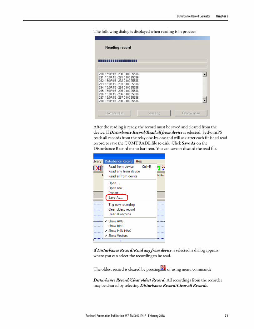
Disturbance Record Evaluator Chapter 5
The following dialog is displayed when reading is in process:
After the reading is ready, the record must be saved and cleared from the device. If Disturbance Record/Read all from device is selected, SetPointPS reads all records from the relay one-by-one and will ask after each finished read record to save the COMTRADE file to disk. Click Save As on the Disturbance Record menu bar item. You can save or discard the read file.
If Disturbance Record/Read any from device is selected, a dialog appears where you can select the recording to be read.
The oldest record is cleared by pressing or using menu command:
Disturbance Record/Clear oldest Record. All recordings from the recorder may be cleared by selecting Disturbance Record/Clear all Records.
Rockwell Automation Publication 857-PM001C-EN-P - February 2018 71
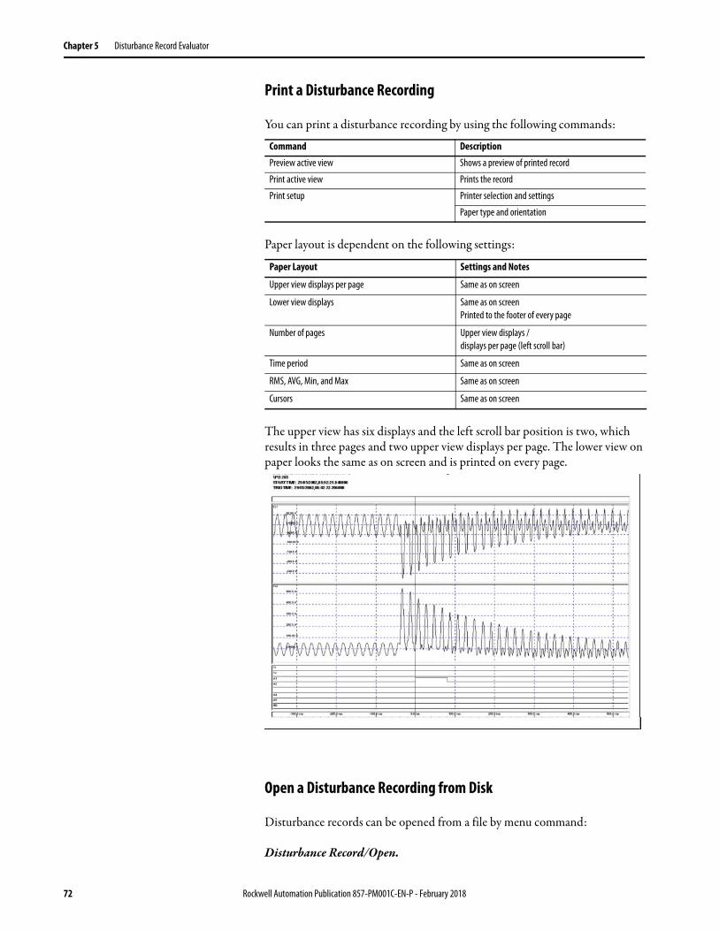
Chapter 5 Disturbance Record Evaluator
Print a Disturbance Recording
You can print a disturbance recording by using the following commands:
Paper layout is dependent on the following settings:
The upper view has six displays and the left scroll bar position is two, which results in three pages and two upper view displays per page. The lower view on paper looks the same as on screen and is printed on every page.
Open a Disturbance Recording from Disk
Disturbance records can be opened from a file by menu command:
Disturbance Record/Open.
Command Description
Preview active view Shows a preview of printed record
Print active view Prints the record
Print setup Printer selection and settings
Paper type and orientation
Paper Layout Settings and Notes
Upper view displays per page Same as on screen
Lower view displays Same as on screenPrinted to the footer of every page
Number of pages Upper view displays / displays per page (left scroll bar)
Time period Same as on screen
RMS, AVG, Min, and Max Same as on screen
Cursors Same as on screen
72 Rockwell Automation Publication 857-PM001C-EN-P - February 2018

Disturbance Record Evaluator Chapter 5
Channel Displays Adding
Use the following sequence to add a display.
1. Select one or more channels from the Channel List.
2. Press to add a display to the Upper View or to the Lower View. The display contains all selected channels.
Removing
To remove one or more displays:
1. Double-click one or more displays to select them.
2. Remove the selected displays by pressing .
Remove all displays by pressing .
Changing the Viewing Configuration
Using the Display Buttons
The following buttons are used for zooming:
Axis Direction Button Note
Time In
Out
View all
Amplitude In If displays or channels are selected, only those will be zoomed. All displays and channels are zoomed.Out
View all
Rockwell Automation Publication 857-PM001C-EN-P - February 2018 73
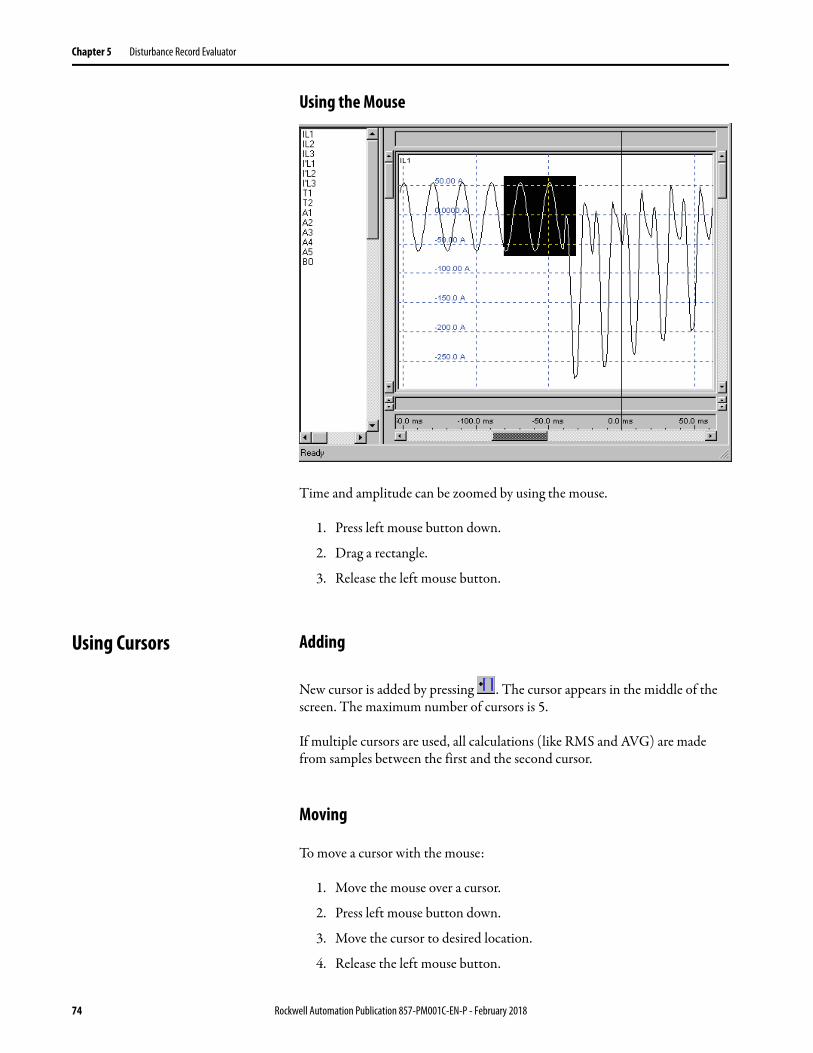
Chapter 5 Disturbance Record Evaluator
Using the Mouse
Time and amplitude can be zoomed by using the mouse.
1. Press left mouse button down.
2. Drag a rectangle.
3. Release the left mouse button.
Using Cursors Adding
New cursor is added by pressing . The cursor appears in the middle of the screen. The maximum number of cursors is 5.
If multiple cursors are used, all calculations (like RMS and AVG) are made from samples between the first and the second cursor.
Moving
To move a cursor with the mouse:
1. Move the mouse over a cursor.
2. Press left mouse button down.
3. Move the cursor to desired location.
4. Release the left mouse button.
74 Rockwell Automation Publication 857-PM001C-EN-P - February 2018

Disturbance Record Evaluator Chapter 5
Removing
All cursors are removed by pressing .
Locking Together
Distances between cursors can be locked by pressing and unlocked by .
Locking can be used, for example, to examine instant RMS values of a waveform display:
1. Add two cursors.
2. Move one cursor to one cycle distance from the other.
3. Lock the cursors together.
4. Enable RMS calculation.
The displayed RMS value is calculated from samples between the two cursors.
5. Move one cursor with the mouse.
The RMS value is updated in real time.
Rockwell Automation Publication 857-PM001C-EN-P - February 2018 75

Chapter 5 Disturbance Record Evaluator
Calculations Calculations Values
SetPointPS can calculate RMS and Average values and show min & max from recorded samples. Calculations are based on samples between the first and last sample or between two cursors, if they exist.
Calculations can be activated from the Disturbance Record menu:
Other Functions Finding the Trigger Point
The trigger point is found easily by pressing .
Resetting All Views
Press to reset all views to the initial state.
The views will look the same as after opening the record from a disk or after reading the record from device:
• analog channels are in the upper view• digital channels are in the lower view• all cursors are removed• amplitudes are zoomed to fit in the display• time is zoomed to show all record
76 Rockwell Automation Publication 857-PM001C-EN-P - February 2018

Chapter 6
Troubleshooting Communication Configurations
There are few things that can be checked and verified if there are any problems in communication between 857/865 relays and your PC running SetPointPS.
Check for Current Version of SetPointPS
The SetPointPS version is checked from the command section.
Click Help>About.
TIP Download the latest software version at: http://ab.rockwellautomation.com/circuit-and-load-protection/medium-voltage/865-medium-voltage-protection#/tab4
Rockwell Automation Publication 857-PM001C-EN-P - February 2018 77

Chapter 6 Troubleshooting Communication Configurations
SetPointPS and Relay Settings
Change Communication Speed
Communication speed must be same in the SetPointPS and in the relay. • Click Settings, and Communication settings.
The factory-default communication speed of the relay is 38400 bps. The default communication speed of SetPointPS is also 38400 bps.
The communication speed is increased or decreased via the operator interface panel, or if a Configurator password has been entered in SetPointPS and a connection is already working between SetPointPS and the relay from:
• Mimic • Local panel display • Local Panel Conf
78 Rockwell Automation Publication 857-PM001C-EN-P - February 2018

Troubleshooting Communication Configurations Chapter 6
If you haven’t set the configurators password, the following text appears:
If the screen above is displayed:
1. Press info .
2. Press Enter .
Set configurators password by using Right and UP arrow buttons. The factory default password is 0002 for the Configurator level of access (0001 is for the Operator level).
3. Press Enter .
Communication Port
The Microsoft Windows communications port must be selected in SetPointPS (see page 78). Select Settings>Communication Settings to change the communication port setting in SetPointPS.
If there are numerous communications channels shown and you don’t know which the right one is, disconnect the cable from the PC and open the Communication settings again and check which COM port disappeared from the menu.
Alternatively,
1. Click the Windows Start button, and click Control Panel.
2. Click System>Hardware>Device Manager.
3. Click Ports (COM&LPT).
Rockwell Automation Publication 857-PM001C-EN-P - February 2018 79
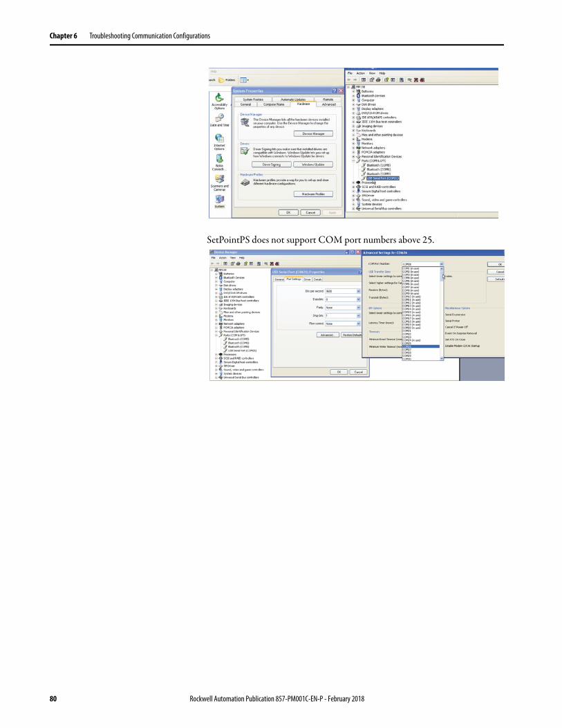
Chapter 6 Troubleshooting Communication Configurations
SetPointPS does not support COM port numbers above 25.
80 Rockwell Automation Publication 857-PM001C-EN-P - February 2018

Troubleshooting Communication Configurations Chapter 6
Connection Cable and Adapters
There is special RS-232 serial cable to connect a PC to an 857 or 865 relay: 857-VX-003.
If a USB to serial adapter is used, Rockwell Automation recommends the following adapters:
• Rockwell Automation Bulletin 9300-USBS• FTDI CHIP ES-U-1001-R100/ US232R-100• ATEN USB-to-Serial (RS-232) Converter Model UC-232A
The drivers for any USB-Serial adapter must also be up to date. Update the drivers using the device manager. You must be connected to the internet.
Incorrect Configuration Password
Sometimes a connection is successful but SetPointPS does not accept the password. If this occurs,
1. Verify that the correct password is entered.
2. Restart SetPointPS and connect to relay again.
3. Cycle power to the relay, which restarts the relay.
Error Messages An error “File is incompatible with the device. Cannot connect...” message could appear when connecting to the relay or when downloading a settings file to a relay.
There are three possible reasons for this error.
IMPORTANT If an incorrect password is tried more than three times, the relay restricts access for 30 minutes or you will need to restart the relay.
Device type is different. A file from a Rockwell Automation Bulletin 865 relay cannot be sent to a Rockwell Automation Bulletin 857 relay.
The major version number is different.
A V6.21 file cannot be sent to a device that has V10.55 firmware, because the major version numbers are different (6.xx versus10.xx).Version number can be checked from the DEVICE INFO view.
The minor version number of the file is greater than the version on device.
For example, a V10.96 file cannot be sent to device that has V10.61 firmware, because the minor version of the file is greater.
Rockwell Automation Publication 857-PM001C-EN-P - February 2018 81

Chapter 6 Troubleshooting Communication Configurations
Notes:
82 Rockwell Automation Publication 857-PM001C-EN-P - February 2018

Appendix A
Virtual Measurement Tool
Initialize Virtual Measurement Function
Virtual measurement functionality is available on 857 and 865 relays with firmware version 10.96 or later. The Virtual Measurement tool makes it possible to inject simulated currents and voltages, including 2nd, 3rd, and 5th harmonic content, into the relay. This tool permits a simple testing method of the protection settings within the relay without an external secondary injection testing device. This function validates the protection settings within the relay without applying power to the load. You must have a relay connected using the SetPointPS software to use this tool.
1. Connect to a relay via the SetPointPS program and log in to the Configurator Mode to enable the use of the virtual measurement functionality feature.
2. Click the Enable Virtual Measurement checkbox to engage and move the window.
3. If the tool is not visible, place the mouse pointer on the far right edge of the SetPointPS main window, until the cursor changes to a horizontal arrow.
4. Once the cursor changes state, hold the right mouse button and drag the border to the left.
5. Click the Enable virtual measurement checkbox. An example of the control mechanism is shown on page 84.
Rockwell Automation Publication 857-PM001C-EN-P - February 2018 83

Appendix A Virtual Measurement Tool
The length of the virtual measurement depends on the frequency used and the number of cycles. If the frequency is 60 Hz and the number of cycles is set at 300, the injected length of the virtual signals is 300/60=5 seconds
A Minimum/Maximum
Permits adjust a maximum value for all of analog signals.
B Test Level The actual setting value within the maximum range of the current, voltage, and earth fault settings.
C Phase Angle
Adjust of the phase angle of any of the used signal (0...360 degrees, positive or negative). You can also change the phasor relationships between the current and voltages using the slider bars on the right of the maximum range values.
D Sequence Create up to a maximum of 5 different sequence/profiles. To create a sequence, click one of the five numbered tabs to open another sequence window. To run a sequence, click "Run Sequence".
E Cycles You must enter a value greater than zero to enable a sequence. Enter then number of current/voltage cycles to run the test profile. To initiate the virtual measurement process, press the Go button next to where you entered the number of cycles. The time length of the virtual measurement process depends on the frequency that is used and the number of cycles entered (see Frequency).
F Frequency The default frequency that is used by the software is 50.000 Hz (50 cycles/s). To change the frequency to another value, you type in a new frequency in place of the 50.000 value. The injected time length that the virtual signals are injected in the test routine is calculated as follows:The total time of one routine is determined by dividing the number of cycles by the frequency entered. For example, 100 cycles/60.0 Hz= 1.67 s.
G Repeats The sequence or sequences are launched by pressing the Run sequence button. Any sequence tabs that have a Cycles entry greater than one will be initiated in numerical order. There is be no delay between the executions of the programmed values of each sequence window. You can also repeat the sequence without any extra delay. You can also run a specific number of sequences or one sequence by entering the number of times you want to repeat the sequence.
H Angular Offset
Normally left at 0. Can be adjusted from 0…180°.
84 Rockwell Automation Publication 857-PM001C-EN-P - February 2018

Virtual Measurement Tool Appendix A
Create and Inject Profiles and Sequences
The tool permits one current/voltage injection sequence or it permits the creation of up to five current/voltage profiles. To create a sequence, open another sequence window by clicking on one of the 5 tabs and add a value greater than zero to the Cycles field. Launch the by pressing the Run sequence button. There will be no delay between the sequence windows. You can also repeat a sequence without any extra delay by entering the number of sequences in the Repeats area.
Virtual COMTRADE Files Virtual COMTRADE files can be loaded into the device that is exercised under the conditions that are contained in the COMTRADE file. The relay behavior is analyzed by playing the recorder data repeatedly in the relay memory.
Open Virtual COMTRADE Files
1. Click "Disturbance record" on the menu bar.
2. Select Open from the pull-down menu (A).
3. Select the COMTRADE file from your hard disk or other storage media. SetPointPS is now ready to read the recording.
4. Enable the Virtual Measurement Tool (B) to send record data to therelay (C).
Profile/Sequence Tabs
Run one profile once
Run a sequence ofprofiles to be
repeated as indicated
IMPORTANT This is not applicable to the arc protection functions of the device.
Rockwell Automation Publication 857-PM001C-EN-P - February 2018 85

Appendix A Virtual Measurement Tool
5. Initiate playback of the file by pressing the GO button (D).
Clicking "Charge to control mode" returns to the virtual measurement.
A
C
B
D
TIP The sample rate of the COMTRADE file must be 32 samples/cycle. The channel names must correspond to the channel names in 857 and 865 relays: IL1, IL2, IL3, Io1, Io2, U12, U23, UL1, UL2, UL3 and Uo.
86 Rockwell Automation Publication 857-PM001C-EN-P - February 2018

Appendix B
Disturbance Recording Example
Evaluation This disturbance recording has been read from the relay. The default display shows the recording, so all the signals are in separate graphs.
The view is arranged for analyzing, so the currents and voltages are displayed in separate own graphs by following procedure:
1. To clear the view, press .
2. Hold Control and select the currents from the signal list using the mouse.
3. To plot the selected signals in the upper view, press .
Rockwell Automation Publication 857-PM001C-EN-P - February 2018 87

Appendix B Disturbance Recording Example
4. Select the voltages from the signal list and press .
The voltage waveforms plot in the lower graph.
5. To add cursors when the recording display is as desired, press .
If multiple cursors are added, SetPointPS displays the time difference between the cursors and the measurement value of each cursor.
TIP Use the zoom buttons to enlarge desired areas of the graph.
88 Rockwell Automation Publication 857-PM001C-EN-P - February 2018

Disturbance Recording Example Appendix B
Import Older Recordings
1. Read the recording from the relay or open with SetPointPS.
2. Select Disturbance Record.
3. Click Import and select the desired disturbance recording.
4. Click “Open”.
Repeat the Import procedure as necessary to retrieve all desired recordings to the SetPointPS.
The signal list for the disturbance recording is displayed on the left side of the window.
5. To clear the display, press .
6. Select the desired signals to be evaluated from the signal list by using mouse click and Control button pressed. Plot the signals to SetPointPS
by pressing button and evaluate the recordings.
Rockwell Automation Publication 857-PM001C-EN-P - February 2018 89

Appendix B Disturbance Recording Example
Retrieve Vector Data
For the waveform data, SetPointPS can show the phase vectors within the cursors.
1. Read from the relay or open the desired waveform disturbance recording.
2. Press to clear the view and plot currents and voltages to their own
graphs .
90 Rockwell Automation Publication 857-PM001C-EN-P - February 2018

Disturbance Recording Example Appendix B
3. To add the cursor to the graph, press .
The graph now shows cursor with the phasor vectors.
4. Double-click any of the curves to show detailed vector data with reference to the other waveforms.
In this example, voltage signal UB has been selected as the phasor display reference, and the signal curve is shown as bold in the upper graph. To change the reference to another signal, double-click another curve.
Phasors in the graphs shows vector relationships to the same selected reference. By moving the cursors in the recording, the phasors change according to the measurement data.
Voltage Signal UB
Rockwell Automation Publication 857-PM001C-EN-P - February 2018 91

Appendix B Disturbance Recording Example
Notes:
92 Rockwell Automation Publication 857-PM001C-EN-P - February 2018

Index
Aadapter 81average values
calculate 76
Bbasic groups 32
protection stage groups 32block matrix 36
Ccable schematics 7cata configuration 45channel displays 73
add 73remove 73
clear events 48communication protocol 40
857-RAA 46857-RAD 46change 40ModBus 41PROFIBUS 43SPA-Bus 41
communication settings 11adapters 81change speed 78connection cable 81port 79
compatibility 8connect 20
quick connect 20connection cable 81
Ddata configuration
analog 45digital 45
date 59deadband 42device
information 31library 15read events 47search 21select 21
disturbance recorder 63calculations 76controls 69example 87import older recordings 89main window 63print record 72print recording from disk 72read from device 70retriece vector data 90sample rate 67select channel 67settings 65toolbar 65trigger 69
Eerror messages 81event buffer 33event logs 46events 46
clear 48enable 46read from device 47save to sisk 48
export files 24
Ffault logs 46
read from device 48files
EDS 24export 24ICD 24IIFD 24load 28save 28SCD 24
firmware 21update 21
functions 57add connection 57add/select logic output connections 58delete 59remove connection 58
Ggroup refresh 14
IIEC 60870-5-103 44
ASDU6 response time 44bit rate 44conifgure 44meas sending interval 44slave number 44
initial reading 14
Rockwell Automation Publication 857-PM001C-EN-P - February 2018 93

Index
input signals 57
Llanguage 22
update 22local panel display 34log files 15logic editor 55
add first function 55add input signals 57function properties 56select input signals 57
logic function propertiescount setting 56output setting 56time off 56time on 56type 56
Mmain window 25
caption view 25channel list 64distance view 64DR info 64group list 25group view 25lower view 64menu bar 25status bar 25time view 64toolbar 25upper view 64
matrix groups 35block matrix 36output matrix 35place connection 37
menusettings 11
mimic editor 49add lines 52add objects 53add, delete, and move text 54clear display 49delete objects, text, and lines 54location information 52select measurement 50send to device 55virtual buttons 51
ModBus 41address 42deadband 42enable 42scaling 42
Ooperating system 8output matrix 35
Pparameter values 39
change 39passwords
configurator 26default 16incorrect password 81operator 26user 26
phase angle diagrams 33event buffer 33local panel display 34
PROFIBUS 43offset 43on/off 43scaling 43
protection stage groups 32fault log 32stage enabling 32stage status 32
Qquick connect 21
Rrampling rate 67rear remote port 7relay configuration 24RMS values
calculate 76
Ssampling rate
overflow 67saturated 67
save events to disk 48scaling 42search device 21select device 21SerCom-file 61
generate 61serial port connection 11settings 11
communication 11communication protocol 40compare 60disturbance recorder 65group refresh 14IEC 60870-5-103 44ModBus 41PROFIBUS 43program 13read all 26read/write 16reading 14SPA-Bus 41trigger 69view 14
94 Rockwell Automation Publication 857-PM001C-EN-P - February 2018

Index
SPA-Bus 41address 41bit rate 41
stage settings 32
Ttime 59trigger point
find 76troubleshooting 77
Uupdate
check version 77firmware 21language 22
Vvector data 90version
download 8view 14
reset all 76virtual comtrade files 85
open 85virtual measurement tool 83
configuration 83create profiles 85create sequences 85virtual comtrade files 85
WWAC.See settings
Rockwell Automation Publication 857-PM001C-EN-P - February 2018 95

Index
Notes:
96 Rockwell Automation Publication 857-PM001C-EN-P - February 2018


Publication 857-PM001C-EN-P - February 2018 Supersedes Publication 857-PM001B-EN-P - February 2013 Copyright © 2018 Rockwell Automation, Inc. All rights reserved. Printed in Canada.
Rockwell Automation SupportUse the following resources to access support information.
Documentation FeedbackYour comments will help us serve your documentation needs better. If you have any suggestions on how to improve this document, complete the How Are We Doing? form at http://literature.rockwellautomation.com/idc/groups/literature/documents/du/ra-du002_-en-e.pdf.
Technical Support Center Knowledgebase Articles, How-to Videos, FAQs, Chat, User Forums, and Product Notification Updates. https://rockwellautomation.custhelp.com/
Local Technical Support Phone Numbers Locate the phone number for your country. http://www.rockwellautomation.com/global/support/get-support-now.page
Direct Dial Codes Find the Direct Dial Code for your product. Use the code to route your call directly to a technical support engineer. http://www.rockwellautomation.com/global/support/direct-dial.page
Literature Library Installation Instructions, Manuals, Brochures, and Technical Data. http://www.rockwellautomation.com/global/literature-library/overview.page
Product Compatibility and Download Center (PCDC)
Get help determining how products interact, check features and capabilities, and find associated firmware. http://www.rockwellautomation.com/global/support/pcdc.page
.
Rockwell Otomasyon Ticaret A.Ş., Kar Plaza İş Merkezi E Blok Kat:6 34752 İçerenköy, İstanbul, Tel: +90 (216) 5698400
Rockwell Automation maintains current product environmental information on its website at http://www.rockwellautomation.com/rockwellautomation/about-us/sustainability-ethics/product-environmental-compliance.page.
Allen-Bradley, Rockwell Automation, and Rockwell Software are trademarks of Rockwell Automation, Inc.
Trademarks not belonging to Rockwell Automation are property of their respective companies.