programming cg-svp01b-en troubleshooting guide the manual literature change history cg-svp01b-en ......
TRANSCRIPT

Trane has a policy of continuous product and product dataimprovement and reserves the right to change design andspecifications without notice. Only qualified technicians shouldperform the installation and servicing of equipment referred toin this publication.
Programming CG-SVP01B-ENTroubleshootingGuide
Library Service Literature
Product Section Refrigeration
Product Hermetic Scroll Liquid Chillers, Air Cooled
Model CG
Literature Type Programming, Trouble Shooting Guide
Sequence 01B
Date January 2005
File No. SV-RF-CG-SVP01B-EN 1/05
Supersedes CG-SVP01A-EN 4/03
IntelliPak��Air-Cooled Cold Generator
Models"H" and Later Design Sequence CGAF-C20 CGAF-C40 CGAF-C25 CGAF-C50 CGAF-C30 CGAF-C60
With 3-DTM Scroll Compressors
��2005 American Standard Inc. All rights reservedhttp://www.trane.com

2
About The ManualLiterature Change History
CG-SVP01B-EN (January 2005)Original issue of this manual; provides specific program-ming, diagnostic, and troubleshooting information CGAFunits with “K” and later design sequence.
Overview of Manual
Note: One copy of this document ships inside thecontrol panel of each unit and is customerproperty. It must be retained by the unit’smaintenance personnel.
These units are equipped with electronic control moduleswhich provides operating functions that are significantly dif-ferent than conventional units.
The manual is divided into 6 sections. Each section pro-vides the operator with specific information about the sys-tem operating parameters and their related screens. Bycarefully following the screen layout within this manualwhile scrolling through the Human Interface, the operatorcan monitor operating status, set specific operating param-eters, and diagnose system problems.
Before attempting to operate or service this equipment, re-fer to the “Start-Up” and “Test Mode” procedures in the ap-plicable Installation, Operation and Maintenance manual,listed on the unit nameplate.
Note: The procedures discussed in this manualshould only be performed by qualified, experiencedHVAC technicians.
Refer to the Table of Contents and Index for specific topicscontained in this manual and supporting manuals.
3
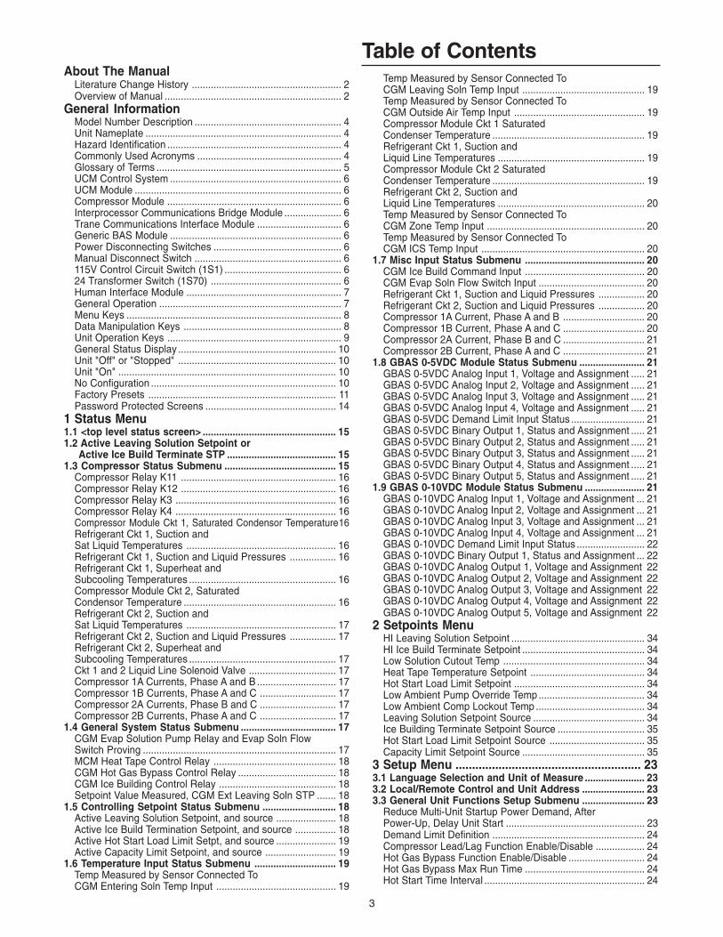
Table of ContentsAbout The Manual
Literature Change History ....................................................... 2Overview of Manual ................................................................. 2
General InformationModel Number Description ...................................................... 4Unit Nameplate ........................................................................ 4Hazard Identification ................................................................ 4Commonly Used Acronyms ..................................................... 4Glossary of Terms .................................................................... 5UCM Control System ............................................................... 6UCM Module ............................................................................ 6Compressor Module ................................................................ 6Interprocessor Communications Bridge Module ..................... 6Trane Communications Interface Module ............................... 6Generic BAS Module ............................................................... 6Power Disconnecting Switches ............................................... 6Manual Disconnect Switch ...................................................... 6115V Control Circuit Switch (1S1) ........................................... 624 Transformer Switch (1S70) ................................................ 6Human Interface Module ......................................................... 7General Operation ................................................................... 7Menu Keys ............................................................................... 8Data Manipulation Keys .......................................................... 8Unit Operation Keys ................................................................ 9General Status Display .......................................................... 10Unit "Off" or "Stopped" .......................................................... 10Unit "On" ................................................................................ 10No Configuration .................................................................... 10Factory Presets ..................................................................... 11Password Protected Screens ................................................ 14
1 Status Menu1.1 <top level status screen> ................................................. 151.2 Active Leaving Solution Setpoint or Active Ice Build Terminate STP ........................................ 151.3 Compressor Status Submenu ......................................... 15
Compressor Relay K11 ......................................................... 16Compressor Relay K12 ......................................................... 16Compressor Relay K3 ........................................................... 16Compressor Relay K4 ........................................................... 16Compressor Module Ckt 1, Saturated Condensor Temperature16Refrigerant Ckt 1, Suction andSat Liquid Temperatures ....................................................... 16Refrigerant Ckt 1, Suction and Liquid Pressures ................. 16Refrigerant Ckt 1, Superheat andSubcooling Temperatures ...................................................... 16Compressor Module Ckt 2, SaturatedCondensor Temperature ........................................................ 16Refrigerant Ckt 2, Suction andSat Liquid Temperatures ....................................................... 17Refrigerant Ckt 2, Suction and Liquid Pressures ................. 17Refrigerant Ckt 2, Superheat andSubcooling Temperatures ...................................................... 17Ckt 1 and 2 Liquid Line Solenoid Valve ................................ 17Compressor 1A Currents, Phase A and B ............................. 17Compressor 1B Currents, Phase A and C ............................ 17Compressor 2A Currents, Phase B and C ............................ 17Compressor 2B Currents, Phase A and C ............................ 17
1.4 General System Status Submenu ................................... 17CGM Evap Solution Pump Relay and Evap Soln FlowSwitch Proving ....................................................................... 17MCM Heat Tape Control Relay ............................................. 18CGM Hot Gas Bypass Control Relay .................................... 18CGM Ice Building Control Relay ........................................... 18Setpoint Value Measured, CGM Ext Leaving Soln STP ....... 18
1.5 Controlling Setpoint Status Submenu ........................... 18Active Leaving Solution Setpoint, and source ...................... 18Active Ice Build Termination Setpoint, and source ............... 18Active Hot Start Load Limit Setpt, and source ...................... 19Active Capacity Limit Setpoint, and source .......................... 19
1.6 Temperature Input Status Submenu .............................. 19Temp Measured by Sensor Connected ToCGM Entering Soln Temp Input ............................................ 19
Temp Measured by Sensor Connected ToCGM Leaving Soln Temp Input ............................................. 19Temp Measured by Sensor Connected ToCGM Outside Air Temp Input ................................................ 19Compressor Module Ckt 1 SaturatedCondenser Temperature ........................................................ 19Refrigerant Ckt 1, Suction andLiquid Line Temperatures ...................................................... 19Compressor Module Ckt 2 SaturatedCondenser Temperature ........................................................ 19Refrigerant Ckt 2, Suction andLiquid Line Temperatures ...................................................... 20Temp Measured by Sensor Connected ToCGM Zone Temp Input .......................................................... 20Temp Measured by Sensor Connected ToCGM ICS Temp Input ............................................................ 20
1.7 Misc Input Status Submenu ............................................ 20CGM Ice Build Command Input ............................................ 20CGM Evap Soln Flow Switch Input ....................................... 20Refrigerant Ckt 1, Suction and Liquid Pressures ................. 20Refrigerant Ckt 2, Suction and Liquid Pressures ................. 20Compressor 1A Current, Phase A and B .............................. 20Compressor 1B Current, Phase A and C .............................. 20Compressor 2A Current, Phase B and C .............................. 21Compressor 2B Current, Phase A and C .............................. 21
1.8 GBAS 0-5VDC Module Status Submenu ........................ 21GBAS 0-5VDC Analog Input 1, Voltage and Assignment ..... 21GBAS 0-5VDC Analog Input 2, Voltage and Assignment ..... 21GBAS 0-5VDC Analog Input 3, Voltage and Assignment ..... 21GBAS 0-5VDC Analog Input 4, Voltage and Assignment ..... 21GBAS 0-5VDC Demand Limit Input Status ........................... 21GBAS 0-5VDC Binary Output 1, Status and Assignment ..... 21GBAS 0-5VDC Binary Output 2, Status and Assignment ..... 21GBAS 0-5VDC Binary Output 3, Status and Assignment ..... 21GBAS 0-5VDC Binary Output 4, Status and Assignment ..... 21GBAS 0-5VDC Binary Output 5, Status and Assignment ..... 21
1.9 GBAS 0-10VDC Module Status Submenu ...................... 21GBAS 0-10VDC Analog Input 1, Voltage and Assignment ... 21GBAS 0-10VDC Analog Input 2, Voltage and Assignment ... 21GBAS 0-10VDC Analog Input 3, Voltage and Assignment ... 21GBAS 0-10VDC Analog Input 4, Voltage and Assignment ... 21GBAS 0-10VDC Demand Limit Input Status ......................... 22GBAS 0-10VDC Binary Output 1, Status and Assignment ... 22GBAS 0-10VDC Analog Output 1, Voltage and Assignment 22GBAS 0-10VDC Analog Output 2, Voltage and Assignment 22GBAS 0-10VDC Analog Output 3, Voltage and Assignment 22GBAS 0-10VDC Analog Output 4, Voltage and Assignment 22GBAS 0-10VDC Analog Output 5, Voltage and Assignment 22
2 Setpoints MenuHI Leaving Solution Setpoint ................................................. 34HI Ice Build Terminate Setpoint ............................................. 34Low Solution Cutout Temp .................................................... 34Heat Tape Temperature Setpoint .......................................... 34Hot Start Load Limit Setpoint ................................................ 34Low Ambient Pump Override Temp....................................... 34Low Ambient Comp Lockout Temp ........................................ 34Leaving Solution Setpoint Source ......................................... 34Ice Building Terminate Setpoint Source ................................ 35Hot Start Load Limit Setpoint Source ................................... 35Capacity Limit Setpoint Source ............................................. 35
3 Setup Menu ........................................................ 233.1 Language Selection and Unit of Measure ...................... 233.2 Local/Remote Control and Unit Address ....................... 233.3 General Unit Functions Setup Submenu ....................... 23
Reduce Multi-Unit Startup Power Demand, AfterPower-Up, Delay Unit Start ................................................... 23Demand Limit Definition ........................................................ 24Compressor Lead/Lag Function Enable/Disable .................. 24Hot Gas Bypass Function Enable/Disable ............................ 24Hot Gas Bypass Max Run Time ............................................ 24Hot Start Time Interval ........................................................... 24
4
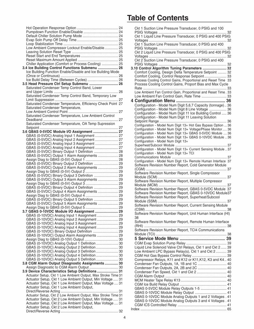
Table of ContentsCkt 1 Suction Line Pressure Transducer, 0 PSIG and 100PSIG Voltages ....................................................................... 32Ckt 1 Liquid Line Pressure Transducer, 0 PSIG and 400 PSIGVoltages ................................................................................. 32Ckt 1 Suction Line Pressure Transducer, 0 PSIG and 400PSIG Voltages ....................................................................... 32Ckt 2 Liquid Line Pressure Transducer, 0 PSIG and 400 PSIGVoltages ................................................................................. 32Ckt 2 Suction Line Pressure Transducer, 0 PSIG and 400PSIG Voltages ....................................................................... 32
3.10 Control Algorithm Tuning Parameters ......................... 32Comfort Cooling, Design Delta Temperature Setpoint ......... 32Comfort Cooling, Control Response Setpoint ....................... 33Process Cooling Control Gains, Proportional and Reset Time 33Process Cooling Control Gains, Proport Bias and Max CycleRate ....................................................................................... 33Low Ambient Fan Control Gain, Proportional and Reset Time . 33Low Ambient Fan Control Gain, Rate Time .......................... 33
4 Configuration Menu .......................................... 36Configuration - Model Num Digit 5,6,7 Capacity (tonnage) .. 36Configuration - Model Num Digit 8 Line Voltage .................. 36Configuration - Model Num Digit 11 Ice Building Control ..... 36Configuration - Model Num Digit 11 Leaving SolutionSetpoint Range ...................................................................... 36Configuration - Model Num Digit 13+ Hot Gas Bypass Option ... 36Configuration - Model Num Digit 13+ Voltage/Phase Monitor ..... 36Configuration - Model Num Digit 13+ GBAS 0-5VDC Module .... 36Configuration - Model Num Digit 13+ GBAS 0-10VDC Module .. 36Configuration - Model Num Digit 13+Superheat/Subcool Module ........................................................... 37Configuration - Model Num Digit 13+ Current Sensing Module .. 37Configuration - Model Num Digit 13+ TCICommunications Module ............................................................... 37Configuration - Model Num Digit 13+ Remote Human Interface 37Software Revision Number Report, Cold Generator Module(CGM) .................................................................................... 37Software Revision Number Report, Single CompressorModule (SCM) ........................................................................ 37Software Revision Number Report, Multiple CompressorModule (MCM) ....................................................................... 37Software Revision Number Report, GBAS 0-5VDC Module 37Software Revision Number Report, GBAS 0-10VDC Module37Software Revision Number Report, Superheat/SubcoolModule (SSM) ........................................................................ 37Software Revision Number Report, Current Sensing Module(CSM) ..................................................................................... 38Software Revision Number Report, Unit Human Interface (HI)38Software Revision Number Report, Remote Human Interface(RHI) ...................................................................................... 38Software Revision Number Report, TCI4 CommunicationsModule (TCI) .......................................................................... 385 Service Mode Menu ....................................... 39����������� ������������� ������������������������������������������ ��Liquid Line Solenoid Valve Ctrl Relays, Ckt 1 and Ckt 2 ...... 39Low Ambient LPC Bypass Relay(s), Ckt 1 and Ckt 2 ........... 39CGM Hot Gas Bypass Control Relay .................................... 39Compressor Relays, K11 and K12 or K11,K12, K3 and K4 .. 40Condenser Fan Outputs, 1A, 1B and 1C .............................. 40Condenser Fan Outputs, 2A, 2B and 2C .............................. 40Condenser Fan Speed, Ckt 1 and Ckt 2 ............................... 40CGM Alarm Output ................................................................ 40MCM Heater Tape Relay K13 ................................................ 40CGM Ice Build Relay Output ................................................. 41GBAS 0-5VDC Module Relay Outputs 1-5 ........................... 41GBAS 0-10VDC Module Relay Output ................................. 41GBAS 0-10VDC Module Analog Outputs 1 and 2 Voltages . 41GBAS 0-10VDC Module Analog Outputs 3 and 4 Voltages . 41CGM ICS Controlled Relay ................................................... 41
Index .......................................................................................... 65
Hot Operation Response Option ........................................... 24Pumpdown Function Enable/Disable .................................... 24Default Chiller Solution Pump Mode ..................................... 24Evap Soln Pump Off Delay Time ........................................... 25Loop Stabilization Time ......................................................... 25Low Ambient Compressor Lockout Enable/Disable .............. 25Leaving Solution Reset Type ................................................ 25Reset Start and End Temperatures ....................................... 25Reset Maximum Amount Applied .......................................... 25Chiller Application (Comfort or Process Cooling) ................. 25
3.4 Ice Building Control Functions Submenu ..................... 26Ice Building Function Enable/Disable and Ice Building Mode(Once or Continuous) ............................................................ 26Ice Build Delay Time (Between Cycles) ................................ 26
3.5 Head Pressure Ctrl Setup Submenu .............................. 26Saturated Condenser Temp Control Band, Lowerand Upper Limits ................................................................... 26Saturated Condenser Temp Control Band, Temporary LowLimit Suppression .................................................................. 27Saturated Condenser Temperature, Efficiency Check Point 27Saturated Condenser Temperature,Low Ambient Control Point .................................................... 27Saturated Condenser Temperature, Low Ambient ControlDeadband .............................................................................. 27Saturated Condenser Temperature, OA Temp SupressionSetpoint .................................................................................. 27
3.6 GBAS 0-5VDC Module I/O Assignment .......................... 27GBAS (0-5VDC) Analog Input 1 Assignment ........................ 27GBAS (0-5VDC) Analog Input 2 Assignment ........................ 27GBAS (0-5VDC) Analog Input 3 Assignment ........................ 27GBAS (0-5VDC) Analog Input 4 Assignment ........................ 27GBAS (0-5VDC) Binary Output 1 Definition ......................... 28GBAS (0-5VDC) Output 1 Alarm Assignments ..................... 28Assign Diag to GBAS (0-5V) Output 1 .................................. 28GBAS (0-5VDC) Binary Output 2 Definition ......................... 29GBAS (0-5VDC) Output 2 Alarm Assignments ..................... 29Assign Diag to GBAS (0-5V) Output 2 .................................. 29GBAS (0-5VDC) Binary Output 3 Definition ......................... 29GBAS (0-5VDC) Output 3 Alarm Assignments ..................... 29Assign Diag to GBAS (0-5V) Output 3 .................................. 29GBAS (0-5VDC) Binary Output 4 Definition ......................... 29GBAS (0-5VDC) Output 4 Alarm Assignments ..................... 29Assign Diag to GBAS (0-5V) Output 4 .................................. 29GBAS (0-5VDC) Binary Output 5 Definition ......................... 29GBAS (0-5VDC) Output 5 Alarm Assignments ..................... 29Assign Diag to GBAS (0-5V) Output 5 .................................. 29
3.7 GBAS 0-10VDC Module I/O Assignment ........................ 29GBAS (0-10VDC) Analog Input 1 Assignment ...................... 29GBAS (0-10VDC) Analog Input 2 Assignment ...................... 29GBAS (0-10VDC) Analog Input 3 Assignment ...................... 29GBAS (0-10VDC) Analog Input 4 Assignment ...................... 29GBAS (0-10VDC) Binary Output Definition .......................... 29GBAS (0-10VDC) Output Alarm Assignments ...................... 29Assign Diag to GBAS (0-10V) Output ................................... 30GBAS (0-10VDC) Analog Output 1 Definition ....................... 30GBAS (0-10VDC) Analog Output 2 Definition ....................... 30GBAS (0-10VDC) Analog Output 3 Definition ....................... 30GBAS (0-10VDC) Analog Output 4 Definition ....................... 30GBAS (0-10VDC) Analog Output 5 Definition ....................... 30
3.8 CGM Alarm Output Disagnostic Assignments .............. 30Assign Diagnostic to CGM Alarm Output .............................. 30
3.9 Device Characteristics Setup Definitions ...................... 31Actuator Setup, Ckt 1 Low Ambient Output, Max Stroke Time 31Actuator Setup, Ckt 1 Low Ambient Output, Min Voltage ..... 31Actuator Setup, Ckt 1 Low Ambient Output, Max Voltage .... 31Actuator Setup, Ckt 1 Low Ambient Output,Direct/Reverse Acting ............................................................ 31Actuator Setup, Ckt 2 Low Ambient Output, Max Stroke Time 31Actuator Setup, Ckt 2 Low Ambient Output, Min Voltage ..... 31Actuator Setup, Ckt 2 Low Ambient Output, Max Voltage .... 31Actuator Setup, Ckt 2 Low Ambient Output,Direct/Reverse Acting ............................................................ 32
5
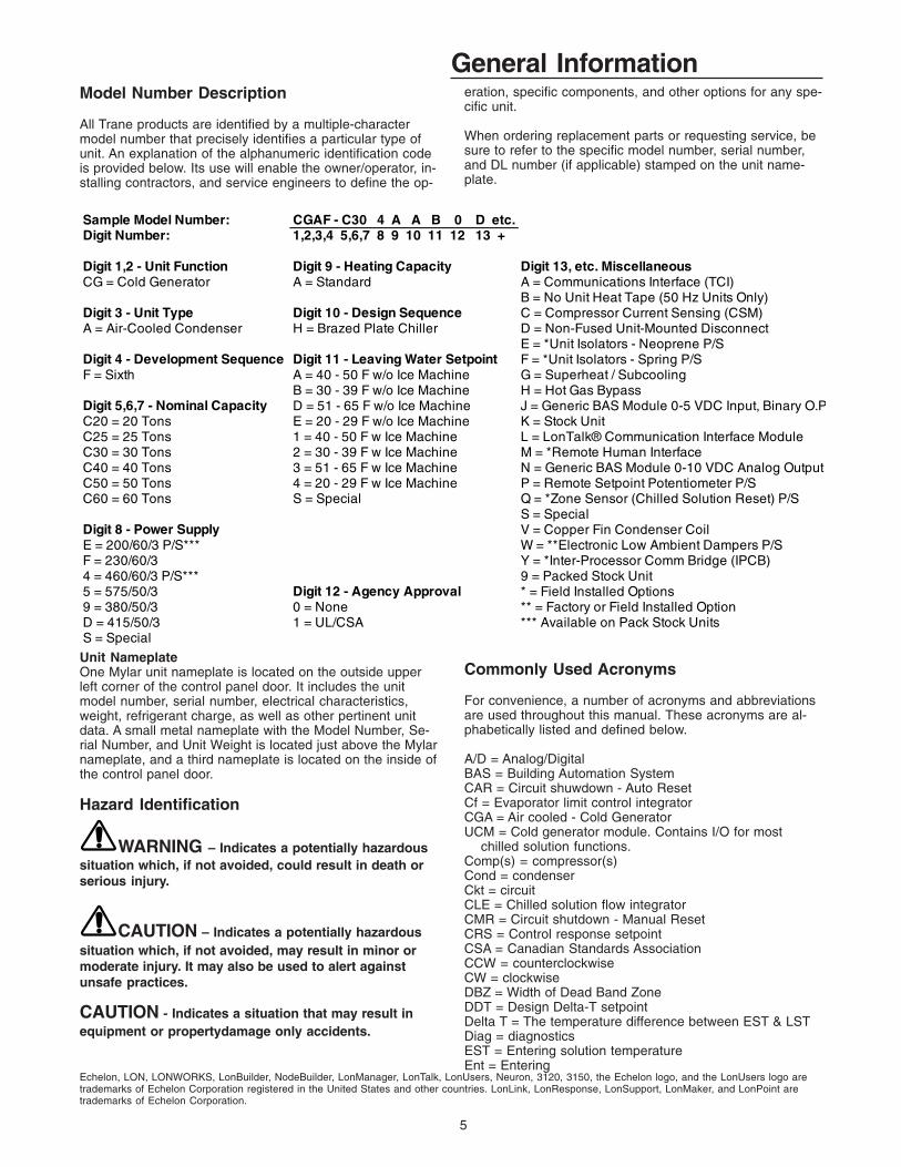
General InformationModel Number Description
All Trane products are identified by a multiple-charactermodel number that precisely identifies a particular type ofunit. An explanation of the alphanumeric identification codeis provided below. Its use will enable the owner/operator, in-stalling contractors, and service engineers to define the op-
eration, specific components, and other options for any spe-cific unit.
When ordering replacement parts or requesting service, besure to refer to the specific model number, serial number,and DL number (if applicable) stamped on the unit name-plate.
Sample Model Number: CGAF - C30 4 A A B 0 D etc.Digit Number: 1,2,3,4 5,6,7 8 9 10 11 12 13 +
Digit 1,2 - Unit Function Digit 9 - Heating Capacity Digit 13, etc. MiscellaneousCG = Cold Generator A = Standard A = Communications Interface (TCI)
B = No Unit Heat Tape (50 Hz Units Only)Digit 3 - Unit Type Digit 10 - Design Sequence C = Compressor Current Sensing (CSM)A = Air-Cooled Condenser H = Brazed Plate Chiller D = Non-Fused Unit-Mounted Disconnect
E = *Unit Isolators - Neoprene P/SDigit 4 - Development Sequence Digit 11 - Leaving Water Setpoint F = *Unit Isolators - Spring P/SF = Sixth A = 40 - 50 F w/o Ice Machine G = Superheat / Subcooling
B = 30 - 39 F w/o Ice Machine H = Hot Gas BypassDigit 5,6,7 - Nominal Capacity D = 51 - 65 F w/o Ice Machine J = Generic BAS Module 0-5 VDC Input, Binary O.PC20 = 20 Tons E = 20 - 29 F w/o Ice Machine K = Stock UnitC25 = 25 Tons 1 = 40 - 50 F w Ice Machine L = LonTalk® Communication Interface ModuleC30 = 30 Tons 2 = 30 - 39 F w Ice Machine M = *Remote Human InterfaceC40 = 40 Tons 3 = 51 - 65 F w Ice Machine N = Generic BAS Module 0-10 VDC Analog OutputC50 = 50 Tons 4 = 20 - 29 F w Ice Machine P = Remote Setpoint Potentiometer P/SC60 = 60 Tons S = Special Q = *Zone Sensor (Chilled Solution Reset) P/S
S = SpecialDigit 8 - Power Supply V = Copper Fin Condenser Coil E = 200/60/3 P/S*** W = **Electronic Low Ambient Dampers P/S F = 230/60/3 Y = *Inter-Processor Comm Bridge (IPCB)4 = 460/60/3 P/S*** 9 = Packed Stock Unit5 = 575/50/3 Digit 12 - Agency Approval * = Field Installed Options9 = 380/50/3 0 = None ** = Factory or Field Installed OptionD = 415/50/3 1 = UL/CSA *** Available on Pack Stock UnitsS = Special
Unit NameplateOne Mylar unit nameplate is located on the outside upperleft corner of the control panel door. It includes the unitmodel number, serial number, electrical characteristics,weight, refrigerant charge, as well as other pertinent unitdata. A small metal nameplate with the Model Number, Se-rial Number, and Unit Weight is located just above the Mylarnameplate, and a third nameplate is located on the inside ofthe control panel door.
Hazard Identification
WARNING – Indicates a potentially hazardoussituation which, if not avoided, could result in death orserious injury.
CAUTION – Indicates a potentially hazardoussituation which, if not avoided, may result in minor ormoderate injury. It may also be used to alert againstunsafe practices.
CAUTION - Indicates a situation that may result inequipment or propertydamage only accidents.
Commonly Used Acronyms
For convenience, a number of acronyms and abbreviationsare used throughout this manual. These acronyms are al-phabetically listed and defined below.
A/D = Analog/DigitalBAS = Building Automation SystemCAR = Circuit shuwdown - Auto ResetCf = Evaporator limit control integratorCGA = Air cooled - Cold GeneratorUCM = Cold generator module. Contains I/O for most
chilled solution functions.Comp(s) = compressor(s)Cond = condenserCkt = circuitCLE = Chilled solution flow integratorCMR = Circuit shutdown - Manual ResetCRS = Control response setpointCSA = Canadian Standards AssociationCCW = counterclockwiseCW = clockwiseDBZ = Width of Dead Band ZoneDDT = Design Delta-T setpointDelta T = The temperature difference between EST & LSTDiag = diagnosticsEST = Entering solution temperatureEnt = Entering
Echelon, LON, LONWORKS, LonBuilder, NodeBuilder, LonManager, LonTalk, LonUsers, Neuron, 3120, 3150, the Echelon logo, and the LonUsers logo aretrademarks of Echelon Corporation registered in the United States and other countries. LonLink, LonResponse, LonSupport, LonMaker, and LonPoint aretrademarks of Echelon Corporation.

6
General InformationEvap = EvaporatorExt = ExternalGBAS = Generic Building Automation System Modulegfm = gallons per minuteHGBP = Hot gas bypassHI = Human InterfaceHO = History OnlyHSLLS = Hot Start Load Limit setpointHVAC = Heating, Ventilation and Air ConditioningIAR = Information only Auto ResetIBTS = Ice Build Terminate SetpointICS = Integrated Comfort SystemIFW = Informational WarningINFO = Information Only [Diagnostic]I/O = Inputs/outputsIOM = installation/operation/maintenance manualIPC = Interprocessor communicationsIPCB Module = Interprocessor communications bridge
moduleIRDT = Ice Rebuild Delay TimerLCD = Liquid Crystal DisplayLCI = LonTalk® Communication InterfaceLCI-I = LonTalk® Communication Interface for IntellipakLED = Light Emitting DiodeLH = left-handLonTalk = An open, device networking communications
protocol for controls. This protocol is defined in ANSIapproved standard EIA/CEA-709.1-A-1999.
LSC = Low Solution Temperature Cutout SetpointLPC = Low Pressure Cutout [Switch]LST = Leaving solution temperatureMAR = Machine shutdown - Auto ResetMax = maximumMCM = Multiple circuit compressor moduleMin = minimumMisc = miscellaneousMMR = Machine shutdown - Manual ResetMod = moduleMon = monitorNCS = Number of capacity stepsnum = numberOA = Outdoor airOAT = Outdoor air TemperaturePAR = Partial System Disable, Auto Reset [Diagnostic]PMR = Partial System Disable, Manual Reset [Diagnostic]PRT = Pump Run TimerPSIG = pounds-per-square-inch gauge pressurePWM = Pulse width modulatedRAM = Random Access MemoryRTM = rooftop moduleROM = Read Only MemoryS/W = SoftwareSat - saturatedSCM = single circuit compressor moduleSCT = Saturated Condensing TemperatureSoln = solutionSTP = setpointTCI Module = Trane communications interface moduleTemp = temperatureUCM = Unit Control ModulesUL = Underwriter's LaboratoriesVFD = Variable Frequency Drivew.c. = water columnXL = across-the-line start
Glossary of TermsCarefully review these definitions since they are usedthroughout this document and the I.O.M.. Knowledge ofthese terms is essential in gaining an understanding of howthese units operate.
Active SetpointThe setpoint which is currently being used for control bythe setpoint source selection.
Comm3Trane proprietary network communication protocol.
Comm5Trane’s implementation of LonTalk (an open networkcommunication protocol.)
Chilled Solution Temperature ResetA function that shifts the Leaving Solution Temp Setpointan amount based on the value of another parameter—typically ZoneTemp, Entering Solution Temp or OutdoorAir Temp. The purpose of this function is to lower unit ca-pacity to better meet load requirements.
Compressor Protection SwitchA pressure switch installed on the suction line that pre-vents compressor operation below the switch's setpoint.
Control BandThe range of temperatures or pressures which wouldnormally be maintained by the various control functions.
Control PointThe value of a setpoint that an algorithm is using at anygiven time.
DeadbandAs applied to LST control, this refers to a range of tem-peratures equally spaced above and below the CSS inwhich the control algorithm is satisfied. There is not ad-justment of machine capacity within the deadband.
Emergency StopUCM binary input. Can be used for emergency shutdownof the unit by field-installed contacts. A diagnostic is pro-duced when this input is open.
External Auto/StopA binary input on the UCM that allows the use of a field-supplied switch to perform normal unit on/off action.
Leaving Solution SetpointActive leaving solution setpoint. This setpoint is the con-trol setpoint for process and comfort cooling.
Leaving Solution Temperature Control PointThe revised temperature setpoint after chilled solutiontemp reset has been applied.
LonTalk©An open, device networking communications protocol forcontrols. This protocol is defined in ANSI approved stan-dard EIA/CEA-709.1-A-1999.
Low Ambient Compressor LockoutA function which prevents compressor operation at lowoutdoor ambient temperatures.
Remote Human InterfaceA human interface module designed to be mounted re-motely from the unit. There will be some functional differ-ences between a unit mounted and a remote mountedhuman interface module.
Reset Amount MaximumThe maximum amount of reset allowed.
Reset End TemperatureThe temperature at which the maximum reset amountwill occur.
Reset Start TemperatureThe temperature at which reset will begin.
Unit Control ModuleThis term is used to describe the set of electronic mod-ules which make up the unit control system.
7
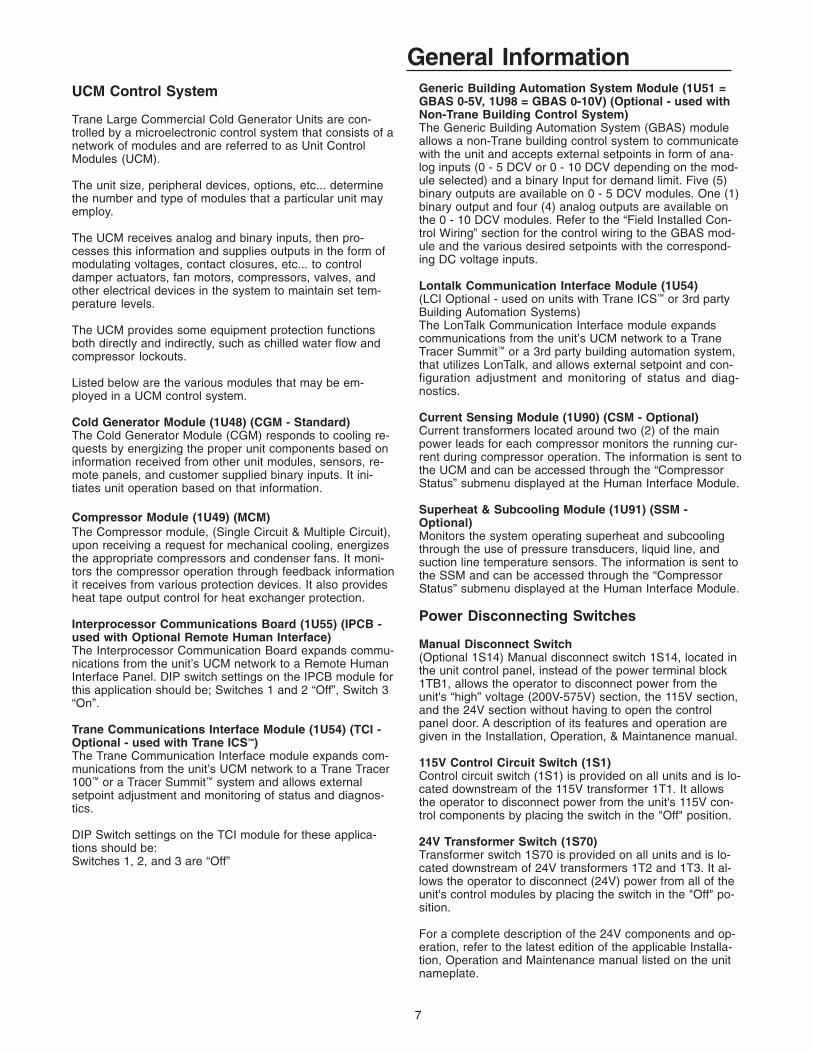
General InformationUCM Control System
Trane Large Commercial Cold Generator Units are con-trolled by a microelectronic control system that consists of anetwork of modules and are referred to as Unit ControlModules (UCM).
The unit size, peripheral devices, options, etc... determinethe number and type of modules that a particular unit mayemploy.
The UCM receives analog and binary inputs, then pro-cesses this information and supplies outputs in the form ofmodulating voltages, contact closures, etc... to controldamper actuators, fan motors, compressors, valves, andother electrical devices in the system to maintain set tem-perature levels.
The UCM provides some equipment protection functionsboth directly and indirectly, such as chilled water flow andcompressor lockouts.
Listed below are the various modules that may be em-ployed in a UCM control system.
Cold Generator Module (1U48) (CGM - Standard)The Cold Generator Module (CGM) responds to cooling re-quests by energizing the proper unit components based oninformation received from other unit modules, sensors, re-mote panels, and customer supplied binary inputs. It ini-tiates unit operation based on that information.
Compressor Module (1U49) (MCM)The Compressor module, (Single Circuit & Multiple Circuit),upon receiving a request for mechanical cooling, energizesthe appropriate compressors and condenser fans. It moni-tors the compressor operation through feedback informationit receives from various protection devices. It also providesheat tape output control for heat exchanger protection.
Interprocessor Communications Board (1U55) (IPCB -used with Optional Remote Human Interface)The Interprocessor Communication Board expands commu-nications from the unit’s UCM network to a Remote HumanInterface Panel. DIP switch settings on the IPCB module forthis application should be; Switches 1 and 2 “Off”, Switch 3“On”.
Trane Communications Interface Module (1U54) (TCI -Optional - used with Trane ICS™)The Trane Communication Interface module expands com-munications from the unit’s UCM network to a Trane Tracer100™ or a Tracer Summit™ system and allows externalsetpoint adjustment and monitoring of status and diagnos-tics.
DIP Switch settings on the TCI module for these applica-tions should be:Switches 1, 2, and 3 are “Off”
Generic Building Automation System Module (1U51 =GBAS 0-5V, 1U98 = GBAS 0-10V) (Optional - used withNon-Trane Building Control System)The Generic Building Automation System (GBAS) moduleallows a non-Trane building control system to communicatewith the unit and accepts external setpoints in form of ana-log inputs (0 - 5 DCV or 0 - 10 DCV depending on the mod-ule selected) and a binary Input for demand limit. Five (5)binary outputs are available on 0 - 5 DCV modules. One (1)binary output and four (4) analog outputs are available onthe 0 - 10 DCV modules. Refer to the “Field Installed Con-trol Wiring” section for the control wiring to the GBAS mod-ule and the various desired setpoints with the correspond-ing DC voltage inputs.
Lontalk Communication Interface Module (1U54)(LCI Optional - used on units with Trane ICS™ or 3rd partyBuilding Automation Systems)The LonTalk Communication Interface module expandscommunications from the unit’s UCM network to a TraneTracer Summit™ or a 3rd party building automation system,that utilizes LonTalk, and allows external setpoint and con-figuration adjustment and monitoring of status and diag-nostics.
Current Sensing Module (1U90) (CSM - Optional)Current transformers located around two (2) of the mainpower leads for each compressor monitors the running cur-rent during compressor operation. The information is sent tothe UCM and can be accessed through the “CompressorStatus” submenu displayed at the Human Interface Module.
Superheat & Subcooling Module (1U91) (SSM -Optional)Monitors the system operating superheat and subcoolingthrough the use of pressure transducers, liquid line, andsuction line temperature sensors. The information is sent tothe SSM and can be accessed through the “CompressorStatus” submenu displayed at the Human Interface Module.
Power Disconnecting Switches
Manual Disconnect Switch(Optional 1S14) Manual disconnect switch 1S14, located inthe unit control panel, instead of the power terminal block1TB1, allows the operator to disconnect power from theunit's “high” voltage (200V-575V) section, the 115V section,and the 24V section without having to open the controlpanel door. A description of its features and operation aregiven in the Installation, Operation, & Maintanence manual.
115V Control Circuit Switch (1S1)Control circuit switch (1S1) is provided on all units and is lo-cated downstream of the 115V transformer 1T1. It allowsthe operator to disconnect power from the unit's 115V con-trol components by placing the switch in the "Off" position.
24V Transformer Switch (1S70)Transformer switch 1S70 is provided on all units and is lo-cated downstream of 24V transformers 1T2 and 1T3. It al-lows the operator to disconnect (24V) power from all of theunit's control modules by placing the switch in the "Off" po-sition.
For a complete description of the 24V components and op-eration, refer to the latest edition of the applicable Installa-tion, Operation and Maintenance manual listed on the unitnameplate.

8
General InformationGeneral Operation
At power-up, the Human Interface LCD will display one ofthree initial screens illustrated in the "General Status" sec-tion.
1. Unit Status (Unit Off or Stopped) (The unit is configuredand operational, but is not running). This screen showsstate, mode, and function information when the unit is offor stopped.
2. Unit Status (Unit On) (The unit is configured and opera-tional, and is running). This screen shows state, mode,and function information when the unit is on.
3. No Configuration (the unit needs to be configured). Thisscreen shows that required configuration data is missing.
The LCD screen has a backlight that makes the informationeasier to read. The light will go out if no keys are pressedfor 30 minutes. If it goes out, simply press the STATUS key.
Human Interface Module
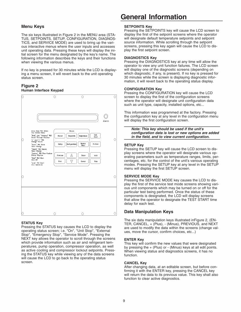
(1U65 = Local 6U66 = Remote)The Human Interface (HI) Module illustrated in Figure 1 isthe device which enables the customer, building owner, orcontractor, to communicate to the unit the necessary pa-rameters for unit operation.
The local (unit mounted) Human Interface and the RemoteHuman Interface Panels’ functions are identical, except forService mode which is not available on the Remote HumanInterface Panel.
The local HI Module is located in the unit’s main controlpanel. A small door located in the unit’s control panel doorallows access to the HI Module’s keypad and display win-dow.
There is a 2 line by 40 character LCD screen which pro-vides status information for the various unit functions aswell as menus used to set or modify the operating param-eters. There is a 16 key keypad adjacent to the LCD screenwhich allows the operator to scroll through the variousmenus and make adjustments to the setpoints, etc...
The information displayed in the LCD window will be toplevel unit status information unless the operator initiatesother displays.
Figure 1Human Interface Module
9
General InformationMenu Keys
The six keys illustrated in Figure 2 in the MENU area (STA-TUS, SETPOINTS, SETUP, CONFIGURATION, DIAGNOS-TICS, and SERVICE MODE) are used to bring up the vari-ous interactive menus where the user inputs and accessesunit operating data. Pressing these keys will display the ini-tial screen for the menu designated by the key’s name. Thefollowing information describes the keys and their functionswhen viewing the various menus.
If no key is pressed for 30 minutes while the LCD is display-ing a menu screen, it will revert back to the unit operatingstatus screen.
Figure 2Human Interface Keypad
STATUS KeyPressing the STATUS key causes the LCD to display theoperating status screen; i.e. "On", "Unit Stop", "ExternalStop", "Emergency Stop", "Service Mode". Pressing theNEXT key allows the operator to scroll through the screenswhich provide information such as air and refrigerant tem-peratures, pump operation, compressor operation, as wellas active cooling and compressor lockout setpoints. Press-ing the STATUS key while viewing any of the data screenswill cause the LCD to go back to the operating statusscreen.
SETPOINTS KeyPressing the SETPOINTS key will cause the LCD screen todisplay the first of the setpoint screens where the operatorwill designate default temperature setpoints and setpointsource information. While scrolling through the setpointscreens, pressing this key again will cause the LCD to dis-play the first setpoint screen.
DIAGNOSTICS KeyPressing the DIAGNOSTICS key at any time will allow theoperator to view any unit function failures. The LCD screenwill display one of the diagnostic screens (depending onwhich diagnostic, if any, is present). If no key is pressed for30 minutes while the screen is displaying diagnostic infor-mation, it will revert back to the operating status display.
CONFIGURATION KeyPressing the CONFIGURATION key will cause the LCDscreen to display the first of the configuration screenswhere the operator will designate unit configuration datasuch as unit type, capacity, installed options, etc...
This information was programmed at the factory. Pressingthe configuration key at any level in the configuration menuwill display the first configuration screen.
Note: This key should be used if the unit'sconfiguration data is lost or new options are addedin the field, and to view current configuration.
SETUP KeyPressing the SETUP key will cause the LCD screen to dis-play screens where the operator will designate various op-erating parameters such as temperature ranges, limits, per-centages, etc. for the control of the unit’s various operatingmodes. Pressing the SETUP key at any level in the SETUPmenu will display the first SETUP screen.
SERVICE MODE KeyPressing the SERVICE MODE key causes the LCD to dis-play the first of the service test mode screens showing vari-ous unit components which may be turned on or off for theparticular test being performed. Once the status of thesecomponents is designated, the LCD will display screensthat allow the operator to designate the TEST START timedelay for each test.
Data Manipulation Keys
The six data manipulation keys illustrated inFigure 2, (EN-TER, CANCEL, + (Plus), - (Minus), PREVIOUS, and NEXTare used to modify the data within the screens (change val-ues, move the cursor, confirm choices, etc...)
ENTER KeyThis key will confirm the new values that were designatedby pressing the + (Plus) or - (Minus) keys at all edit points.When viewing status and diagnostics screens, it has nofunction.
CANCEL KeyAfter changing data, at an editable screen, but before con-firming it with the ENTER key, pressing the CANCEL keywill return the data to its previous value. This key shall alsofunction to clear active diagnostics.
10
General InformationSTOP KeyPressing the STOP key will cause the unit to transition tothe stop state. If the current display is editable, pressing theSTOP key will cancel the desired edit.
TEST START Key (SERVICE)Pressing this key while viewing any screen in the SERVICEMode menu will start the service test. When viewing status,setup, setpoint, and diagnostics screens, it has no function.
CUSTOM KeyThe Custom menu is simply a status menu that containsscreens that the user monitors most frequently. The Custommenu can only contain five status screens. To create theCustom menu, press the STATUS key, followed by theNEXT key (this brings up the initial status screen). If youwant to add this screen to the Custom menu, press the +(Plus) key, if not, press the Next key again until a statusscreen appears that you would like to add to the Custommenu. Pressing the + (Plus) key while viewing any of thevarious status screens will add that screen to the Custommenu. Once the Custom menu is programed it can be ac-cessed by pressing the CUSTOM key. To remove a statusscreen from the Custom menu, press the CUSTOM key,then press the NEXT key until the status screen that youwant to remove appears, then press the - (Minus) key.
+ (Plus) KeyWhen viewing a setpoint screen, this key will increase thetemperature or pressure value of the setpoint. When work-ing with a status menu, it will add the current status displayto the custom menu. When viewing the setup or service testscreens, it will increase setpoints or toggle choices On orOff at each edit point.
- (Minus) KeyThis key when viewing the setpoint screen will decrease thetemperature or pressure value of the setpoint. When view-ing the setup or service test screens, it will decreasesetpoints or toggle choices On or Off at each edit point.When viewing the custom menu, pressing the - (Minus) keywill remove the status screen from the custom menu. Whenviewing diagnostics screens it has no function.
PREVIOUS KeyPressing the PREVIOUS key causes the LCD to scrollbackwards through the various displays for each menu. Atdisplays with multiple edit points, it moves the cursor fromone edit point to another.
NEXT KeyPressing the NEXT key causes the LCD to scroll forwardthrough the various displays for each menu. At displayswith multiple edit points it moves the cursor from one editpoint to another.
Unit Operation Keys
AUTO KeyPressing the AUTO key at any time will cause the display togo to the top level status display and, if the unit is shut-down, will cause the unit to begin operation in the appropri-ate mode no matter what level in the menu structure is cur-rently being displayed. If the current display is an editabledisplay, the AUTO key will confirm the desired edit.
After adding a screen to the Custom menu, the followingscreen is displayed:
“Item Added to Custom Menu”
If the + (PLUS) key is pressed and the Custom menu is full,the following screen is displayed:
“Custom Menu Is Full”
After deleting a screen from the Custom Menu, the follow-ing screen is displayed:
“Item Deleted from Custom Menu”
If the CUSTOM key is pressed and there are no entries, thefollowing screen is displayed:
No items are selected for Custom Report See Operators Manual to select entries

11
General InformationGeneral Status Display
Anytime the unit is powered up, or the STATUS, AUTO, or STOP keys are pressed, the unit mounted Human Interface willdisplay one of the following three general status display screens. The operator will then be able to enter keystrokes whichwill allow him to navigate through a set of menus and submenus in order to provide/access various monitoring, setup, andconfiguration infromation. The Human Interface will not display screens or parts of screens for which the unit is not config-ured.
Unit "Off" or "Stopped"If at power up the unit is not running, the following display will appear on the Human Interface LCD screen. When this screenis being displayed, the only functional keys are the six menu keys (STATUS, SETPOINTS, DIAGNOSTICS, SETUP, CON-FIGURATION, AND SERVICE MODE), the AUTO key, the CUSTOM key, and the STOP key.
Mode of Operation(Blank)
(On)(Off)
Top Level State(External Stop)(Emergency Stop) Trouble Indicator(Unit Shutdown) (Diagnostics)(Unit Stop) (Blank)
_______________ Solution Pump _____
Unit "On"If the unit has entered an operating state (running), the following display will appear on the Human Interface LCD screen.When this screen is being displayed, the only functional keys are the six menu keys (STATUS, SETPOINTS, DIAGNOS-TICS, SETUP, CONFIGURATION, AND SERVICE MODE), the AUTO key, the CUSTOM key, and the STOP key.
Mode of Operation(Cool 0)
(Hot Gas Bypass)(Cool 1)(Cool 2) (On)(Cool 3) (Off)(Cool 4)
(Flow SW State Fail)*
Top Level State(Service Mode On) Ice Building Complete(Comfort Cooling) Ice Rebuild Delay Trouble Indicator(Process Cooling) Unit Standby (Diagnostics)(Ice Building) (Blank)(Loop Stabilization)
*Service Test Mode Only - Flow switch failed to open after solution pump turned off.
_______________ Solution Pump _____ ____________________ ____________________
No ConfigurationIf at power up the unit has not been programmed with the necessary configuration data for normal unit operation, the follow-ing display will appear on the Human Interface LCD screen. When this screen is being displayed, the only functional key isthe CONFIGURATION key.
No Configuration Present Press Configuration Key
Note: This screen will only appear when the CGM has been field replaced. Refer to the Configuration Menu.

12
General InformationFactory Presets
The CGM controlled unit has many operating functionswhose settings are preset at the factory, but may be modi-fied to meet the unique requirements of each job. The fol-lowing list identifies each of the unit's adjustable functionsand the value assigned to it. If these factory presets matchyour application's requirements and the"System Start-Upprocedures in the Installation, Operation & Maintyenancemanual has been completed, simply press the AUTO key atthe Human Interface module to begin unit operation.
If your application requires different settings, turn to thelisted page beside the function, press the designated func-tion menu key, then press and hold the NEXT or PREVI-OUS key until its screen appears on the LCD. Once theproper screen appears, simply follow the programming in-structions given below the applicable screen in this manual.
Note: Record any changes made to the factorypreset values in the corresponding space provided.
Factory Preset Changed See page... To adjustTo to adjust Press....
SetpointsLeaving Solution Setpoint 44 deg F 34 SETPOINTSLow Ambient Compressor Lockout Temperature Setpoint 40 deg F 34 SETPOINTSHeat Tape Temperature Setpoint 40 deg F 34 SETPOINTSHot Start Load Limit Setpoint 71 deg F 34 SETPOINTSIce Building Terminate Temperature 27 deg F 34 SETPOINTSLow Solution Cutout Temperature 35 deg F 34 SETPOINTSLow Ambient Pump Override Temperature 35 deg F 34 SETPOINTSUse Leaving Solution Setpoint From: HI STP Menu 34 SETPOINTSUse Ice Building Terminate Setpoint From: HI STP Menu 34 SETPOINTSUse Hot Start Load Limit Setpoint From: HI STP Menu 35 SETPOINTSUse Capacity Limit Setpoint From: No Source Selected 35 SETPOINTS
Information formatDisplay Text in English Language 23 SETUPDisplay Units in English 23 SETUPUnit Control Local 23 SETUPUnit Address 49 23 SETUP
General Unit Functions SetupDelay unit Start 0 Seconds 23 SETUPDemand Limit Definition None 24 SETUPHot Gas Bypass Function Disabled 24 SETUPHot Gas Bypass Max Run Time 30 Minutes 24 SETUPHot Start Time Interval 60 Minutes 24 SETUPHot Operation Response Option 50% Capacity
(Auto Reset Diag.) 24 SETUPPumpdown Function Disabled 24 SETUPCompressor Lead/Lag Function Disabled 24 SETUPDefault Chiller Solution Pump Mode Auto 24 SETUPEvaporator Solution Pump Off Delay Time 30 Seconds 25 SETUPLoop Stabilization Time 120 Seconds 25 SETUPLow Ambient Compressor Lockout Enabled 25 SETUPLeaving Solution Reset Type None 25 SETUPChiller Application Comfort 25 SETUPEvaporator Solution Flow Switch Proving Disabled 25 SETUPOA Temp Reset Type: Start Temp 70 deg F 25 SETUPOA Temp Reset Type: End Temp 50 deg F 25 SETUPOA Temp Reset Type: Max Amount of Reset 5 deg F 25 SETUPZone Temp Reset Type: Start Temp 78 deg F 25 SETUPZone Temp Reset Type: End Temp 75 deg F 25 SETUPZone Temp Reset Type: Max Amount of Reset 5 deg F 25 SETUPEntering Solution Temp Reset Type: Start Temp 45 deg F 25 SETUPEntering Solution Temp Reset Type: End Temp 40 deg F 25 SETUPEntering Solution Temp Reset Type: Max Amount 5 deg F 25 SETUP

13
General InformationFactory Presets (Continued)
Factory Preset Changed See page... To adjustTo to adjust Press....
Ice Building Control FuctionsIce Building Function Disabled 26 SETUPIce Building Mode One Time 26 SETUPIce Rebuild Delay Time 360 Minutes 26 SETUP
GBAS 0-5 VDC Module I/O AssignmentsGBAS (0-5 VDC) Analog Input 1 Assignment Not Assigned 27 SETUPGBAS (0-5 VDC) Analog Input 2 Assignment Not Assigned 27 SETUPGBAS (0-5 VDC) Analog Input 3 Assignment Not Assigned 27 SETUPGBAS (0-5 VDC) Analog Input 4 Assignment Not Assigned 27 SETUPGBAS (0-5 VDC) Binary Output 1 Definition Indicate any comp
is running 28 SETUPGBAS 0-5 V Output 1 Alarm Assignments Any active diagnostic 28 SETUPGBAS (0-5 VDC) Binary Output 2 Definition Indicate selected
diagnostics 29 SETUPGBAS 0-5 V Output 2 Alarm Assignments Comp protection LPC
Open Ckt 1 29 SETUPComp protection LPC
Open Ckt 2 (40-60 Ton) 29 SETUPCompressor Trip Ckt 1 29 SETUPCompressor Trip Ckt 2
(40 - 60 Ton) 29 SETUPComp Contactor Fail Ckt 1 29 SETUPComp Contactor Fail Ckt 2
(40 - 60 Ton) 29 SETUPLow Press Control
Open - Ckt 1 29 SETUPLow Press Control
Open - Ckt 2 (40-60 Ton) 29 SETUPGBAS (0-5 VDC) Binary Output 3 Definition Indicate Unit at
Max capacity 29 SETUPGBAS (0-5 VDC) Output 3 Alarm Assignments Any active diagnostic 29 SETUPGBAS (0-5 VDC) Binary Output 4 Definition Indicate selected
diag alarms 29 SETUPGBAS (0-5 VDC) Output 4 Alarm Assignments Any active diagnostic 29 SETUPGBAS (0-5 VDC) Binary Output 5 Definition Indicate selected
diag alarms 29 SETUPGBAS (0-5 VDC) Output 5 Alarm Assignments Any active diagnostic 29 SETUP
GBAS 0-10 VDC Module I/O AssignmentsGBAS (0-10 VDC) Analog Input 1 Assignment Not Assigned 29 SETUPGBAS (0-10 VDC) Analog Input 2 Assignment Not Assigned 29 SETUPGBAS (0-10 VDC) Analog Input 3 Assignment Not Assigned 29 SETUPGBAS (0-10 VDC) Analog Input 4 Assignment Not Assigned 29 SETUPGBAS (0-10 VDC) Binary Output Definition Indicate selected
diag alarms 29 SETUPGBAS (0-10 VDC) Output Alarm Assignments Any active diagnostic 30 SETUPGBAS (0-10 VDC) Analog Output 1 Assignment Leaving solution temp 30 SETUPGBAS (0-10 VDC) Analog Output 2 Assignment Entering solution temp 30 SETUPGBAS (0-10 VDC) Analog Output 3 Assignment Active cooling capacity 30 SETUPGBAS (0-10 VDC) Analog Output 4 Assignment Outside air temperature 30 SETUP
CGM alarm output definitions Any Active Diagnostic 30 SETUP
14
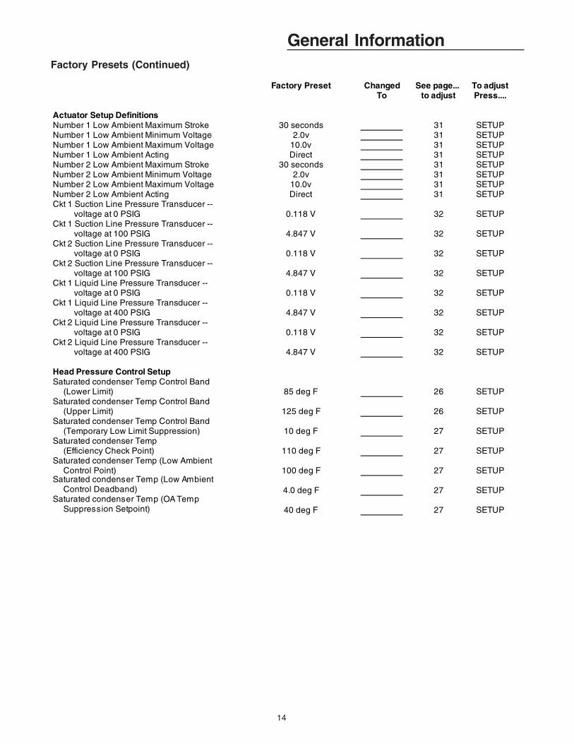
General InformationFactory Presets (Continued)
Factory Preset Changed See page... To adjustTo to adjust Press....
Actuator Setup DefinitionsNumber 1 Low Ambient Maximum Stroke 30 seconds 31 SETUPNumber 1 Low Ambient Minimum Voltage 2.0v 31 SETUPNumber 1 Low Ambient Maximum Voltage 10.0v 31 SETUPNumber 1 Low Ambient Acting Direct 31 SETUPNumber 2 Low Ambient Maximum Stroke 30 seconds 31 SETUPNumber 2 Low Ambient Minimum Voltage 2.0v 31 SETUPNumber 2 Low Ambient Maximum Voltage 10.0v 31 SETUPNumber 2 Low Ambient Acting Direct 31 SETUPCkt 1 Suction Line Pressure Transducer -- voltage at 0 PSIG 0.118 V 32 SETUPCkt 1 Suction Line Pressure Transducer -- voltage at 100 PSIG 4.847 V 32 SETUPCkt 2 Suction Line Pressure Transducer -- voltage at 0 PSIG 0.118 V 32 SETUPCkt 2 Suction Line Pressure Transducer -- voltage at 100 PSIG 4.847 V 32 SETUPCkt 1 Liquid Line Pressure Transducer -- voltage at 0 PSIG 0.118 V 32 SETUPCkt 1 Liquid Line Pressure Transducer -- voltage at 400 PSIG 4.847 V 32 SETUPCkt 2 Liquid Line Pressure Transducer -- voltage at 0 PSIG 0.118 V 32 SETUPCkt 2 Liquid Line Pressure Transducer -- voltage at 400 PSIG 4.847 V 32 SETUP
Head Pressure Control SetupSaturated condenser Temp Control Band (Lower Limit) 85 deg F 26 SETUPSaturated condenser Temp Control Band (Upper Limit) 125 deg F 26 SETUPSaturated condenser Temp Control Band (Temporary Low Limit Suppression) 10 deg F 27 SETUPSaturated condenser Temp (Efficiency Check Point) 110 deg F 27 SETUPSaturated condenser Temp (Low Ambient Control Point) 100 deg F 27 SETUPSaturated condenser Temp (Low Ambient Control Deadband) 4.0 deg F 27 SETUPSaturated condenser Temp (OA Temp Suppression Setpoint) 40 deg F 27 SETUP

15
General InformationPassword Protected Screens
Some of the operating displays on the Human Interface LCD screen are intended to be accessed by qualified users only,and require a password to change. The following screens display the various programming sections that require a passwordin order to view or to modify the preset operating parameters. The password for each screen is a different series of + (Plus)or - (Minus) key strokes in a predefined sequence. Shown below are the password protected screens, and the passwords foraccessing them.
The following screens display the various programming sections that require aspecific PASSWORD to be entered by a qualified operator in order to view or to modify the operating parameters.
The following screen will appear if the PASSWORD is not entered within approximately 15 seconds.
1. Press the NEXT key until the following screen is displayed.
2. Press the + or - keys in this sequence ( + - - - ) to access this restricted screen.3. Press the ENTER key to confirm the password and enter the menu.4. Press the NEXT key until the following screen is displayed.
1. Press the + or - keys in this sequence ( - + + ) to access this restricted screen.2. Press the ENTER key to confirm the password and Lock the definitions.3. Press the NEXT key until the following screen is displayed.
1. Press the + or - keys in this sequence ( - + + -) to access this restricted screen.2. Press the ENTER key to confirm the password and Lock the definitions.3. Press the NEXT key until the following screen is displayed.
Password Entry Time Limit Exceeded
Configuration is Password Protected Please Enter Pasword:
Diagnostic Reset is Password Protected Please Enter Pasword:
Diagnostic Log is Password Protected Please Enter Pasword: __________
16
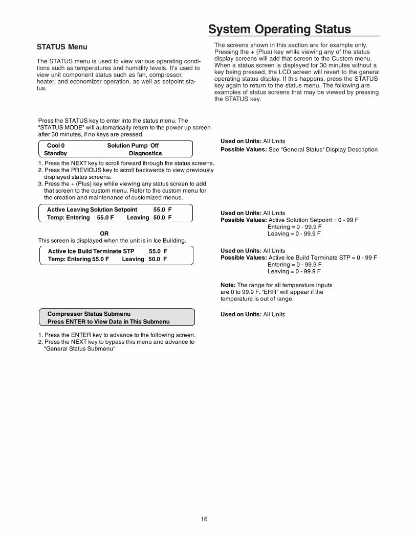
System Operating StatusSTATUS Menu
The STATUS menu is used to view various operating condi-tions such as temperatures and humidity levels. It’s used toview unit component status such as fan, compressor,heater, and economizer operation, as well as setpoint sta-tus.
The screens shown in this section are for example only.Pressing the + (Plus) key while viewing any of the statusdisplay screens will add that screen to the Custom menu.When a status screen is displayed for 30 minutes without akey being pressed, the LCD screen will revert to the generaloperating status display. If this happens, press the STATUSkey again to return to the status menu. The following areexamples of status screens that may be viewed by pressingthe STATUS key.
Press the STATUS key to enter into the status menu. The"STATUS MODE" will automatically return to the power up screenafter 30 minutes, if no keys are pressed.
Used on Units: All UnitsPossible Values: See "General Status" Display Description
1. Press the NEXT key to scroll forward through the status screens.2. Press the PREVIOUS key to scroll backwards to view previously displayed status screens. 3. Press the + (Plus) key while viewing any status screen to add that screen to the custom menu. Refer to the custom menu for the creation and maintenance of customized menus.
Used on Units: All UnitsPossible Values: Active Solution Setpoint = 0 - 99 F Entering = 0 - 99.9 F
OR Leaving = 0 - 99.9 FThis screen is displayed when the unit is in Ice Building.
Used on Units: All UnitsPossible Values: Active Ice Build Terminate STP = 0 - 99 F Entering = 0 - 99.9 F Leaving = 0 - 99.9 F
Note: The range for all temperature inputs are 0 to 99.9 F. "ERR" will appear if the temperature is out of range.
Used on Units: All Units
1. Press the ENTER key to advance to the following screen. 2. Press the NEXT key to bypass this menu and advance to "General Status Submenu"
Cool 0 Solution Pump Off Standby Diagnostics
Active Leaving Solution Setpoint 55.0 F Temp: Entering 55.0 F Leaving 50.0 F
Compressor Status Submenu Press ENTER to View Data in This Submenu
Active Ice Build Terminate STP 55.0 F Temp: Entering 55.0 F Leaving 50.0 F

17
System Operating Status
The following screens are displayed for 20 through 60 Ton units.
Used on Units: 20 thru 60 Ton UnitsPossible Values: K3 - On, Off, Locked, K4 - On, Off, Locked,
1. Press the NEXT key until the following screen is displayed. K11 - On, Off, Locked, or K12 - On, Off, Locked
1. Press the NEXT key until the following screen is displayed.
The following screens are displayed for 40 through 60 Ton units.
1. Press the NEXT key until the following screen is displayed.
Disabled By:Bad Cond Temp Sensor Hot Start OperationBad Ent Soln Sensor Low Ambient LockoutBad Leav Soln Sensor Low Leav Soln CutoutCompressor Protection Low Pressure CutoutCompressor Protect LPC LPC DelayContactor Failure Minimum Off TimeDemand/Capacity Limit Over/Under VoltageEvap Flow Protection Phase Loss/ReversalEvap Limit Control Tracer Lockout
1. Press the NEXT key until the following screen is displayed.
Used on Units: All UnitsPossible Values: -40 to 200 F
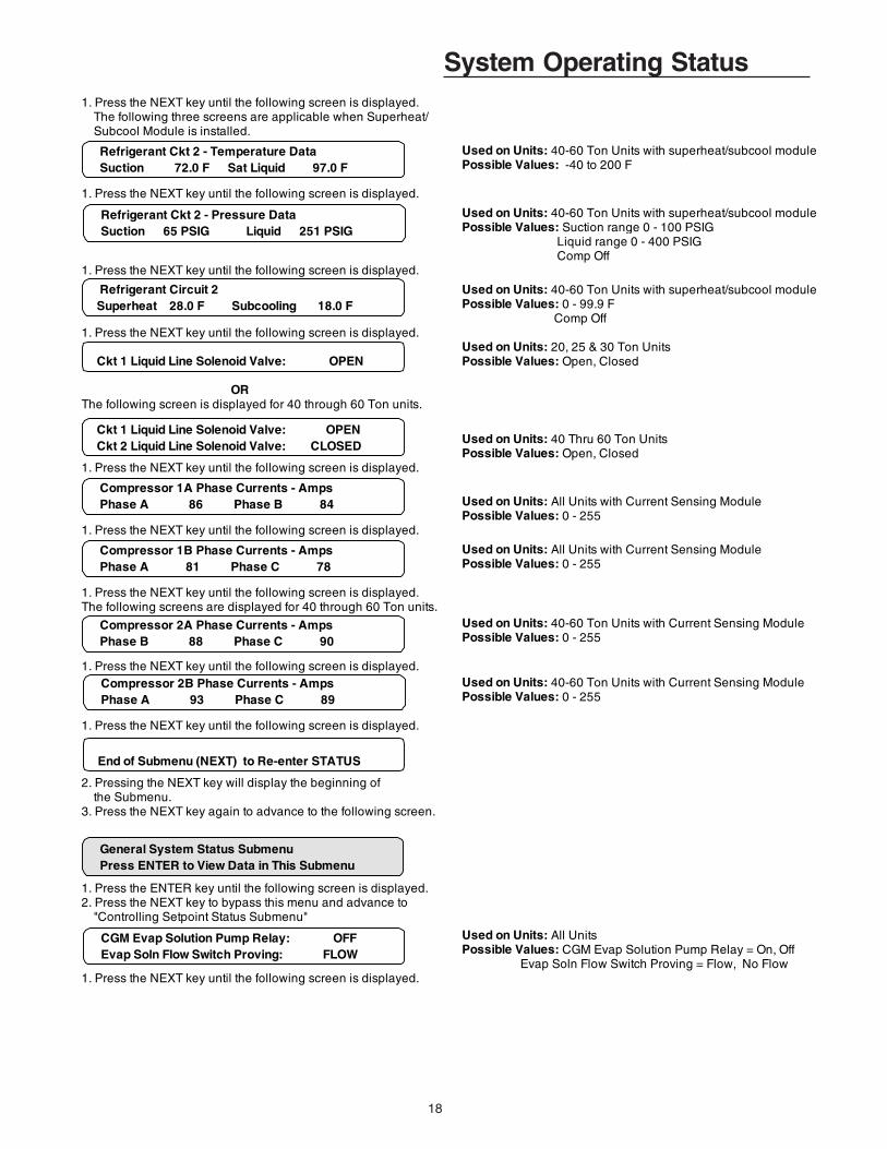
1. Press the NEXT key until the following screen is displayed. The following three screens are applicable when Superheat/ Subcool Module is installed.
Used on Units: With superheat/subcool modulePossible Values: -40 to 200 F
1. Press the NEXT key until the following screen is displayed.
Used on Units: With superheat/subcool modulePossible Values: Suction range 0 - 100 PSIG Liquid range 0 - 400 PSIG
1. Press the NEXT key until the following screen is displayed. Comp Off
Used on Units: With superheat/subcool modulePossible Values: 0 - 99.9 F Comp Off
1. Press the NEXT key until the following screen is displayed.
The following screens are displayed for 40 through 60 Ton units.Used on Units: 40 Thru 60 Ton UnitsPossible Values: -40 to 200 F
Compressor Relay K11 Off Enabled
Compressor Relay K12 Off Enabled
Compressor Relay K3 Off Enabled
Compressor Relay K4 Off Enabled
Compressor Module Ckt 1 Saturated Condensor Temperature 81.0 F
Refrigerant Ckt 1 - Temperature Data Suction 75.0 F Sat Liquid 81.0 F
Refrigerant Ckt 1 - Pressure Data Suction 72 PSIG Liquid 265 PSIG
Refrigerant Circuit 1 Superheat 28.0 F Subcooling 18.0 F
Compressor Module Ckt 2 Saturated Condenser Temperature 97.0 F
18
System Operating Status1. Press the NEXT key until the following screen is displayed. The following three screens are applicable when Superheat/ Subcool Module is installed.
Used on Units: 40-60 Ton Units with superheat/subcool modulePossible Values: -40 to 200 F
1. Press the NEXT key until the following screen is displayed.
Used on Units: 40-60 Ton Units with superheat/subcool modulePossible Values: Suction range 0 - 100 PSIG Liquid range 0 - 400 PSIG Comp Off
1. Press the NEXT key until the following screen is displayed.
Used on Units: 40-60 Ton Units with superheat/subcool modulePossible Values: 0 - 99.9 F Comp Off
1. Press the NEXT key until the following screen is displayed. Used on Units: 20, 25 & 30 Ton UnitsPossible Values: Open, Closed
ORThe following screen is displayed for 40 through 60 Ton units.
Used on Units: 40 Thru 60 Ton UnitsPossible Values: Open, Closed
1. Press the NEXT key until the following screen is displayed.
Used on Units: All Units with Current Sensing Module Possible Values: 0 - 255
1. Press the NEXT key until the following screen is displayed.
Used on Units: All Units with Current Sensing Module Possible Values: 0 - 255
1. Press the NEXT key until the following screen is displayed. The following screens are displayed for 40 through 60 Ton units.
Used on Units: 40-60 Ton Units with Current Sensing Module Possible Values: 0 - 255
1. Press the NEXT key until the following screen is displayed. Used on Units: 40-60 Ton Units with Current Sensing Module Possible Values: 0 - 255
1. Press the NEXT key until the following screen is displayed.
2. Pressing the NEXT key will display the beginning of the Submenu.3. Press the NEXT key again to advance to the following screen.
1. Press the ENTER key until the following screen is displayed. 2. Press the NEXT key to bypass this menu and advance to "Controlling Setpoint Status Submenu"
Used on Units: All UnitsPossible Values: CGM Evap Solution Pump Relay = On, Off Evap Soln Flow Switch Proving = Flow, No Flow
1. Press the NEXT key until the following screen is displayed.
General System Status Submenu Press ENTER to View Data in This Submenu
CGM Evap Solution Pump Relay: OFF Evap Soln Flow Switch Proving: FLOW
Refrigerant Ckt 2 - Temperature Data Suction 72.0 F Sat Liquid 97.0 F
Refrigerant Ckt 2 - Pressure Data Suction 65 PSIG Liquid 251 PSIG
Refrigerant Circuit 2 Superheat 28.0 F Subcooling 18.0 F
Ckt 1 Liquid Line Solenoid Valve: OPEN Ckt 2 Liquid Line Solenoid Valve: CLOSED
Compressor 1A Phase Currents - Amps Phase A 86 Phase B 84
Compressor 1B Phase Currents - Amps Phase A 81 Phase C 78
Compressor 2A Phase Currents - Amps Phase B 88 Phase C 90
Compressor 2B Phase Currents - Amps Phase A 93 Phase C 89
End of Submenu (NEXT) to Re-enter STATUS
Ckt 1 Liquid Line Solenoid Valve: OPEN
19
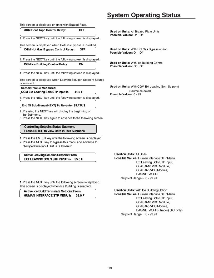
System Operating StatusThis screen is displayed on units with Brazed Plate.
Used on Units: All Brazed Plate UnitsPossible Values: On, Off
1. Press the NEXT key until the following screen is displayed.
This screen is displayed when Hot Gas Bypass is installed.Used on Units: With Hot Gas Bypass optionPossible Values: On, Off
1. Press the NEXT key until the following screen is displayed. Used on Units: With Ice Building ControlPossible Values: On, Off
1. Press the NEXT key until the following screen is displayed.
This screen is displayed when Leaving Solution Setpoint Sourceis selected.
Used on Units: With CGM Ext Leaving Soln Setpoint
Source selectedPossible Values: 0 - 99
1. Press the NEXT key until the following screen is displayed.
2. Pressing the NEXT key will display the beginning of the Submenu.3. Press the NEXT key again to advance to the following screen.
CGM Hot Gas Bypass Control Relay: OFF
End Of Sub-Menu (NEXT) To Re-enter STATUS
CGM Ice Building Control Relay: ON
Setpoint Value MeasuredCGM Ext Leaving Soln STP Input is 44.0 F
MCM Heat Tape Control Relay: OFF
1. Press the ENTER key until the following screen is displayed. 2. Press the NEXT key to bypass this menu and advance to "Temperature Input Status Submenu"
Used on Units: All UnitsPossible Values: Human Interface STP Menu, Ext Leaving Soln STP Input, GBAS 0-10 VDC Module, GBAS 0-5 VDC Module, BAS/NETWORK Setpoint Range = 0 - 99.9 F
1. Press the NEXT key until the following screen is displayed. This screen is displayed when Ice Building is enabled.
Used on Units: With Ice Building OptionPossible Values: Human Interface STP Menu, Ext Leaving Soln STP Input, GBAS 0-10 VDC Module, GBAS 0-5 VDC Module, BAS/NETWORK (Tracer) (TCI only) Setpoint Range = 0 - 99.9 F
Active Leaving Solution Setpoint From EXT LEAVING SOLN STP INPUT is 55.0 F
Active Ice Build Terminate Setpoint From HUMAN INTERFACE STP MENU is 33.0 F
Controlling Setpoint Status Submenu Press ENTER to View Data in This Submenu
20
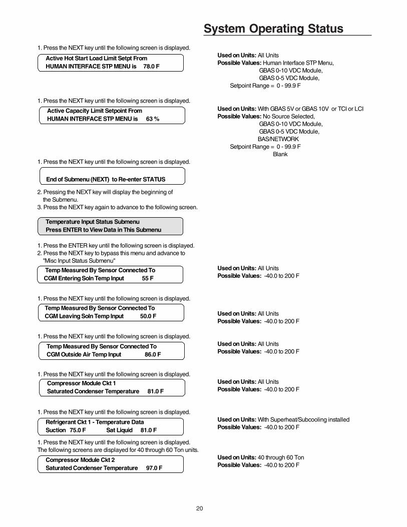
System Operating Status1. Press the NEXT key until the following screen is displayed.
Used on Units: All UnitsPossible Values: Human Interface STP Menu, GBAS 0-10 VDC Module, GBAS 0-5 VDC Module, Setpoint Range = 0 - 99.9 F
1. Press the NEXT key until the following screen is displayed. Used on Units: With GBAS 5V or GBAS 10V or TCI or LCIPossible Values: No Source Selected, GBAS 0-10 VDC Module, GBAS 0-5 VDC Module, BAS/NETWORK Setpoint Range = 0 - 99.9 F Blank
1. Press the NEXT key until the following screen is displayed.
2. Pressing the NEXT key will display the beginning of the Submenu.3. Press the NEXT key again to advance to the following screen.
1. Press the ENTER key until the following screen is displayed. 2. Press the NEXT key to bypass this menu and advance to "Misc Input Status Submenu"
Used on Units: All UnitsPossible Values: -40.0 to 200 F
1. Press the NEXT key until the following screen is displayed.
Used on Units: All UnitsPossible Values: -40.0 to 200 F
1. Press the NEXT key until the following screen is displayed. Used on Units: All UnitsPossible Values: -40.0 to 200 F
1. Press the NEXT key until the following screen is displayed. Used on Units: All UnitsPossible Values: -40.0 to 200 F
1. Press the NEXT key until the following screen is displayed. Used on Units: With Superheat/Subcooling installedPossible Values: -40.0 to 200 F
1. Press the NEXT key until the following screen is displayed. The following screens are displayed for 40 through 60 Ton units.
Used on Units: 40 through 60 TonPossible Values: -40.0 to 200 F
Active Hot Start Load Limit Setpt From HUMAN INTERFACE STP MENU is 78.0 F
Active Capacity Limit Setpoint From HUMAN INTERFACE STP MENU is 63 %
End of Submenu (NEXT) to Re-enter STATUS
Temperature Input Status Submenu Press ENTER to View Data in This Submenu
Temp Measured By Sensor Connected To CGM Entering Soln Temp Input 55 F
Temp Measured By Sensor Connected To CGM Leaving Soln Temp Input 50.0 F
Compressor Module Ckt 1 Saturated Condenser Temperature 81.0 F
Temp Measured By Sensor Connected To CGM Outside Air Temp Input 86.0 F
Compressor Module Ckt 2 Saturated Condenser Temperature 97.0 F
Refrigerant Ckt 1 - Temperature Data Suction 75.0 F Sat Liquid 81.0 F

21
System Operating StatusUsed on Units: 40-60 Ton with Superheat/Subcooling Module installedPossible Values: -40.0 to 200 F
1. Press the NEXT key until the following screen is displayed. Used on Units: All UnitsPossible Values: -40.0 to 200 F
1. Press the NEXT key until the following screen is displayed. Used on Units: With TCI Module InstalledPossible Values: -40.0 to 200 F
1. Press the NEXT key until the following screen is displayed.
2. Pressing the NEXT key will display the beginning of the Submenu.3. Press the NEXT key again to advance to the following screen.
Refrigerant Ckt 2 - Temperature Data Suction 72.0 F Sat Liquid 97.0 F
Temp Measured By Sensor Connected To CGM Zone Temp Input 75.0 F
Temp Measured By Sensor Connected To CGM ICS Temp Input 62.0 F
End of Submenu (NEXT) to Re-enter STATUS
Used on Units: With Ice Building Control OptionPossible Values: Off, Make Ice
1. Press the NEXT key until the following screen is displayed. Used on Units: All UnitsPossible Values: Flow, No Flow
1. Press the NEXT key until the following screen is displayed. Used on Units: All Units with Superheat/SubcoolingPossible Values: Suction = 0.0 to 100.0 PSIG Liquid = 0.0 to 400.0 PSIG Comp Off
1. Press the NEXT key until the following screen is displayed. Used on Units: 40 - 60 Ton Units with Superheat/CoolingPossible Values: Suction = 0.0 to 100.0 PSIG Liquid = 0.0 to 400.0 PSIG Comp Off
1. Press the NEXT key until the following screen is displayed. Used on Units: With Current Sensing ModulePossible Values: 0 to 255
1. Press the NEXT key until the following screen is displayed.
Used on Units: With Current Sensing ModulePossible Values: 0 to 255
CGM Ice Build Command Input: OFF
CGM Evap Soln Flow Switch Input: FLOW
Refrigerant Ckt 1 - Pressure Data Suction 72 PSIG Liquid 265 PSIG
Refrigerant Ckt 2 - Pressure Data Suction 65 PSIG Liquid 251 PSIG
Compressor 1A Phase Currents - Amps Phase A 86 Phase B 84
Compressor 1B Phase Currents - Amps Phase A 81 Phase C 78
1. Press the ENTER key until the following screen is displayed. 2. Press the NEXT key to bypass this menu and advance to "GBAS 0-5VDC Module Status Submenu"
Misc Input Status Submenu Press ENTER to View Data in This Submenu
22
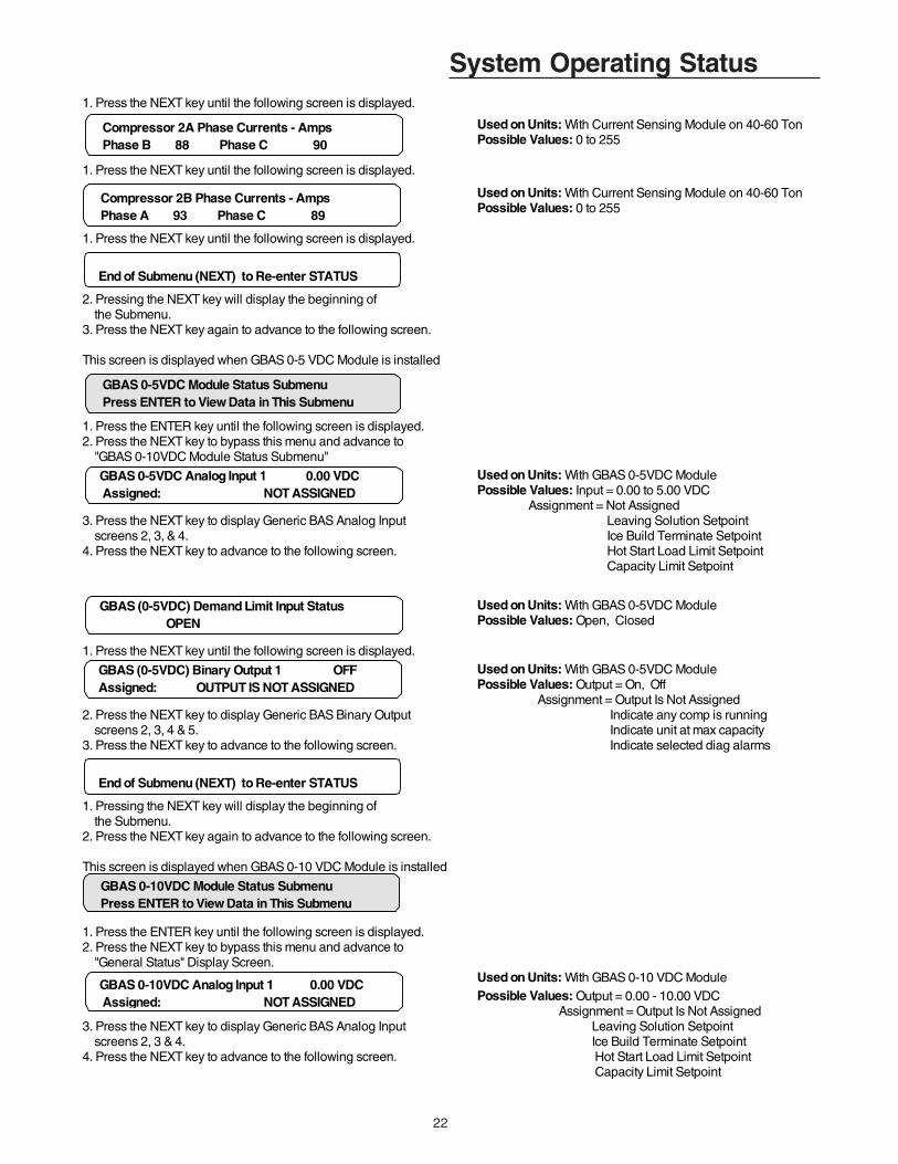
System Operating Status1. Press the NEXT key until the following screen is displayed.
Used on Units: With Current Sensing Module on 40-60 TonPossible Values: 0 to 255
1. Press the NEXT key until the following screen is displayed.
Used on Units: With Current Sensing Module on 40-60 TonPossible Values: 0 to 255
1. Press the NEXT key until the following screen is displayed.
2. Pressing the NEXT key will display the beginning of the Submenu.3. Press the NEXT key again to advance to the following screen.
This screen is displayed when GBAS 0-5 VDC Module is installed
1. Press the ENTER key until the following screen is displayed. 2. Press the NEXT key to bypass this menu and advance to "GBAS 0-10VDC Module Status Submenu"
Used on Units: With GBAS 0-5VDC ModulePossible Values: Input = 0.00 to 5.00 VDC Assignment = Not Assigned
3. Press the NEXT key to display Generic BAS Analog Input Leaving Solution Setpoint screens 2, 3, & 4. Ice Build Terminate Setpoint4. Press the NEXT key to advance to the following screen. Hot Start Load Limit Setpoint
Capacity Limit Setpoint
Used on Units: With GBAS 0-5VDC ModulePossible Values: Open, Closed
1. Press the NEXT key until the following screen is displayed. Used on Units: With GBAS 0-5VDC ModulePossible Values: Output = On, Off Assignment = Output Is Not Assigned
2. Press the NEXT key to display Generic BAS Binary Output Indicate any comp is running screens 2, 3, 4 & 5. Indicate unit at max capacity3. Press the NEXT key to advance to the following screen. Indicate selected diag alarms
1. Pressing the NEXT key will display the beginning of the Submenu.2. Press the NEXT key again to advance to the following screen.
This screen is displayed when GBAS 0-10 VDC Module is installed
1. Press the ENTER key until the following screen is displayed. 2. Press the NEXT key to bypass this menu and advance to "General Status" Display Screen.
Used on Units: With GBAS 0-10 VDC ModulePossible Values: Output = 0.00 - 10.00 VDC Assignment = Output Is Not Assigned
3. Press the NEXT key to display Generic BAS Analog Input Leaving Solution Setpoint screens 2, 3 & 4. Ice Build Terminate Setpoint4. Press the NEXT key to advance to the following screen. Hot Start Load Limit Setpoint
Capacity Limit Setpoint
Compressor 2A Phase Currents - Amps Phase B 88 Phase C 90
Compressor 2B Phase Currents - Amps Phase A 93 Phase C 89
End of Submenu (NEXT) to Re-enter STATUS
GBAS 0-5VDC Module Status Submenu Press ENTER to View Data in This Submenu
GBAS 0-5VDC Analog Input 1 0.00 VDC Assigned: NOT ASSIGNED
GBAS (0-5VDC) Demand Limit Input Status OPEN
GBAS (0-5VDC) Binary Output 1 OFF Assigned: OUTPUT IS NOT ASSIGNED
End of Submenu (NEXT) to Re-enter STATUS
GBAS 0-10VDC Module Status Submenu Press ENTER to View Data in This Submenu
GBAS 0-10VDC Analog Input 1 0.00 VDC Assigned: NOT ASSIGNED

23
System Operating StatusUsed on Units: With GBAS 0-10 VDC Module
Possible Values: Open, Closed
1. Press the NEXT key until the following screen is displayed. Used on Units: With GBAS 0-10 VDC ModulePossible Values: Output = On, Off Assignment = Output Is Not Assigned Indicate selected diag alarms Indicate unit at max capacity Indicate any comp is running
1. Press the NEXT key until the following screen is displayed. Used on Units: With GBAS 0-10 VDC Module
Possible Values: 0.0 to 10.0 VDC
Assignment = Leaving solution temperature Assignment = Ckt1 liquid line pressure Entering solution temperature Ckt2 liquid line pressure Ckt1 saturated condenser temp Ckt1 sat liquid temperature Ckt2 saturated condenser temp Ckt2 sat liquid temperature Ckt1 suction temperature ICS Defined temperature Ckt2 suction temperature Outside air temperature Ckt1 suction pressure Active Cooling Capacity Ckt2 suction pressure
2. Press the NEXT key to display Generic BAS Analog Output screens 2, 3 & 4. 3. Press the NEXT key to advance to the following screen.
4. Pressing the NEXT key will display the beginning of the Submenu.5. Press the AUTO or STOP key to return to the top level status information.
GBAS (0-10VDC) Demand Limit Input Status Open
GBAS (0-10VDC) Binary Output OFF Assigned: OUTPUT IS NOT ASSIGNED
End of Submenu (NEXT) to Re-enter STATUS
GBAS 0-10VDC Analog Output 1 0.0 VDC Assigned: NOT ASSIGNED
24
System Programming SETUPAfter the unit is installed, the CGM must be programmedwith certain setup information (chilled solution setpoints, ONand OFF times, system defaults, setpoint sources, etc...) inorder to operate and function properly. The data necessaryfor unit operation will vary depending on certain factorssuch as unit size, type, and installed options.
This section of the manual provides step by step instruc-tions for programming this information. Also provided are in-structions for checking unit operating status, accessing andclearing diagnostics, and performing service tests.
Some of the displays shown in this manual may not appearon the Human Interface (HI) LCD screen during program-ing. Only the applicable screens for the specific unit optionsand operating parameters will be displayed.
Start with the first setup screen in the SETUP menu andprogram the necessary information by completing the stepslocated below each illustrated window. Information that per-tains to when the screens are applicable, the factory presetvalues, and the possible values that may be designated islocated to the right of each programmable screen.
Ignore the steps that do not apply to your unit and applica-tion, and move on to the next applicable set of instructionsin the manual. Continue this process until all applicablescreens are programmed with the required information.
SETUP Menu
The setup menu is used to input initial operating information such as control parameters, functions enable/disable, text dis-play (language), temperature display (C or F), and system tuning parameters. When a setup screen is displayed for 30 min-utes without a key being pressed, the LCD screen will revert to the appropriate power-up display. If this happens, press theSETUP key again to return to the setup menu.
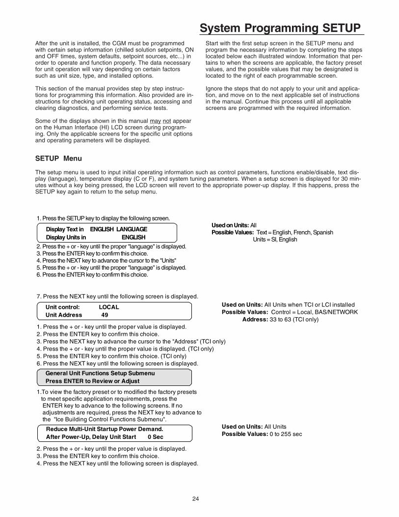
1. Press the SETUP key to display the following screen.Used on Units: AllPossible Values: Text = English, French, Spanish Units = SI, English
2. Press the + or - key until the proper "language" is displayed.3. Press the ENTER key to confirm this choice.4. Press the NEXT key to advance the cursor to the "Units"5. Press the + or - key until the proper "language" is displayed.6. Press the ENTER key to confirm this choice.
Display Text in ENGLISH LANGUAGE Display Units in ENGLISH
7. Press the NEXT key until the following screen is displayed. Used on Units: All Units when TCI or LCI installedPossible Values: Control = Local, BAS/NETWORK Address: 33 to 63 (TCI only)
1. Press the + or - key until the proper value is displayed.2. Press the ENTER key to confirm this choice.3. Press the NEXT key to advance the cursor to the "Address" (TCI only)4. Press the + or - key until the proper value is displayed. (TCI only)5. Press the ENTER key to confirm this choice. (TCI only)6. Press the NEXT key until the following screen is displayed.
1.To view the factory preset or to modified the factory presets to meet specific application requirements, press the ENTER key to advance to the following screens. If no adjustments are required, press the NEXT key to advance to the "Ice Building Control Functions Submenu".
Used on Units: All UnitsPossible Values: 0 to 255 sec
2. Press the + or - key until the proper value is displayed.3. Press the ENTER key to confirm this choice.4. Press the NEXT key until the following screen is displayed.
Unit control: LOCAL Unit Address 49
General Unit Functions Setup Submenu Press ENTER to Review or Adjust
Reduce Multi-Unit Startup Power Demand. After Power-Up, Delay Unit Start 0 Sec
25
System Programming SETUP
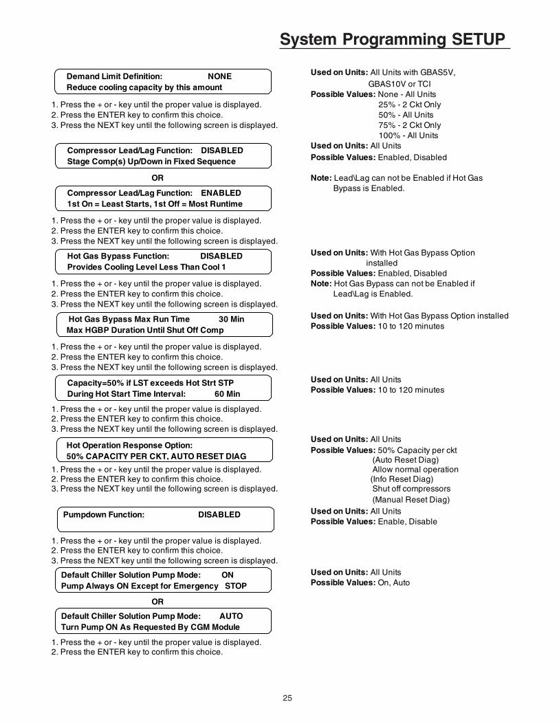
Used on Units: All Units with GBAS5V, GBAS10V or TCIPossible Values: None - All Units
1. Press the + or - key until the proper value is displayed. 25% - 2 Ckt Only 2. Press the ENTER key to confirm this choice. 50% - All Units 3. Press the NEXT key until the following screen is displayed. 75% - 2 Ckt Only
100% - All UnitsUsed on Units: All UnitsPossible Values: Enabled, Disabled
OR Note: Lead\Lag can not be Enabled if Hot Gas Bypass is Enabled.
1. Press the + or - key until the proper value is displayed.2. Press the ENTER key to confirm this choice.3. Press the NEXT key until the following screen is displayed.
Used on Units: With Hot Gas Bypass Option installedPossible Values: Enabled, Disabled
1. Press the + or - key until the proper value is displayed. Note: Hot Gas Bypass can not be Enabled if2. Press the ENTER key to confirm this choice. Lead\Lag is Enabled.3. Press the NEXT key until the following screen is displayed.
Used on Units: With Hot Gas Bypass Option installedPossible Values: 10 to 120 minutes
1. Press the + or - key until the proper value is displayed.2. Press the ENTER key to confirm this choice.3. Press the NEXT key until the following screen is displayed.
Used on Units: All UnitsPossible Values: 10 to 120 minutes
1. Press the + or - key until the proper value is displayed.2. Press the ENTER key to confirm this choice.3. Press the NEXT key until the following screen is displayed.
Used on Units: All UnitsPossible Values: 50% Capacity per ckt (Auto Reset Diag)
1. Press the + or - key until the proper value is displayed. Allow normal operation 2. Press the ENTER key to confirm this choice. (Info Reset Diag)3. Press the NEXT key until the following screen is displayed. Shut off compressors
(Manual Reset Diag)Used on Units: All UnitsPossible Values: Enable, Disable
1. Press the + or - key until the proper value is displayed.2. Press the ENTER key to confirm this choice.3. Press the NEXT key until the following screen is displayed.
Used on Units: All UnitsPossible Values: On, Auto
OR
1. Press the + or - key until the proper value is displayed.2. Press the ENTER key to confirm this choice.
Demand Limit Definition: NONE Reduce cooling capacity by this amount
Compressor Lead/Lag Function: DISABLED Stage Comp(s) Up/Down in Fixed Sequence
Capacity=50% if LST exceeds Hot Strt STP During Hot Start Time Interval: 60 Min
Hot Operation Response Option: 50% CAPACITY PER CKT, AUTO RESET DIAG
Pumpdown Function: DISABLED
Default Chiller Solution Pump Mode: ON Pump Always ON Except for Emergency STOP
Hot Gas Bypass Function: DISABLED Provides Cooling Level Less Than Cool 1
Hot Gas Bypass Max Run Time 30 Min Max HGBP Duration Until Shut Off Comp
Compressor Lead/Lag Function: ENABLED 1st On = Least Starts, 1st Off = Most Runtime
Default Chiller Solution Pump Mode: AUTO Turn Pump ON As Requested By CGM Module

26
System Programming SETUP
Used on Units: All UnitsPossible Values: 30 to 600 seconds
1. Press the + or - key until the proper value is displayed.2. Press the ENTER key to confirm this choice.3. Press the NEXT key until the following screen is displayed.
Used on Units: All UnitsPossible Values: 30 to 255 seconds
1. Press the + or - key until the proper value is displayed.2. Press the ENTER key to confirm this choice.3. Press the NEXT key until the following screen is displayed.
Used on Units: All UnitsPossible Values: Enable, Disable
1. Press the + or - key until the proper value is displayed.2. Press the ENTER key to confirm this choice.3. Press the NEXT key until the following screen is displayed.
Used on Units: All UnitsPossible Values: None - No Reset Applied Outside Air Temp Reset
1. Press the + or - key until the proper value is displayed. Zone Temp Reset2. Press the ENTER key to confirm this choice. Entering Solution Temp Reset3. Press the NEXT key until the following screen is displayed.
The following two screens will display when either OA, Zone, orENT Soln Reset is selected.
1. Press the + or - key until the proper value is displayed. Used on Units: All Units with Leaving Solution Reset2. Press the ENTER key to confirm this choice. Possible Values:3. Press the NEXT key to advance the cursor to the "End Temp" Reset Type: Outside Air Temp Reset4. Press the + or - key until the proper value is displayed. Zone Temp Reset5. Press the ENTER key to confirm this choice. Entering Soln Temp Reset6. Press the NEXT key until the following screen is displayed. Start Temp OA: 46 - 125 F
Zone: 67 - 81 F ENT Soln Temp Reset: 6 - 80 F End Temp OA: 45 - 124 F
1. Press the + or - key until the proper value is displayed. Zone: 66 - 80 F2. Press the ENTER key to confirm this choice. ENT Soln Temp Reset: 5 - 79 F3. Press the NEXT key until the following screen is displayed. Max Amount (Zone, OA, ENT Soln Temp Reset): 3 - 16 F
1. Press the + or - key until the proper value is displayed. Used on Units: All Units2. Press the ENTER key to confirm this choice. Possible Values: Comfort Cooling, Process Cooling3. Press the NEXT key until the following screen is displayed.
Evap Soln Pump Off Delay time 30 Sec Delay Pump OFF Request By This Amount
Loop Stabilization Time: 120 Sec Run Pump To Allow Soln Temp To Stabilize
Low Ambient Compressor Lockout: ENABLED Use Low Ambient Compressor Lockout STP
Leaving Solution Reset Type: NONE - NO RESET APPLIED
Select Type of Cooling Control Based On Chiller Application: PROCESS COOLING
Reset Type: Outside Air Temp Reset Start Temp 70.0 F End Temp 50.0 F
Reset Type: Outside Air Temp Reset Maximum Amount of Reset Applied 5.0 F
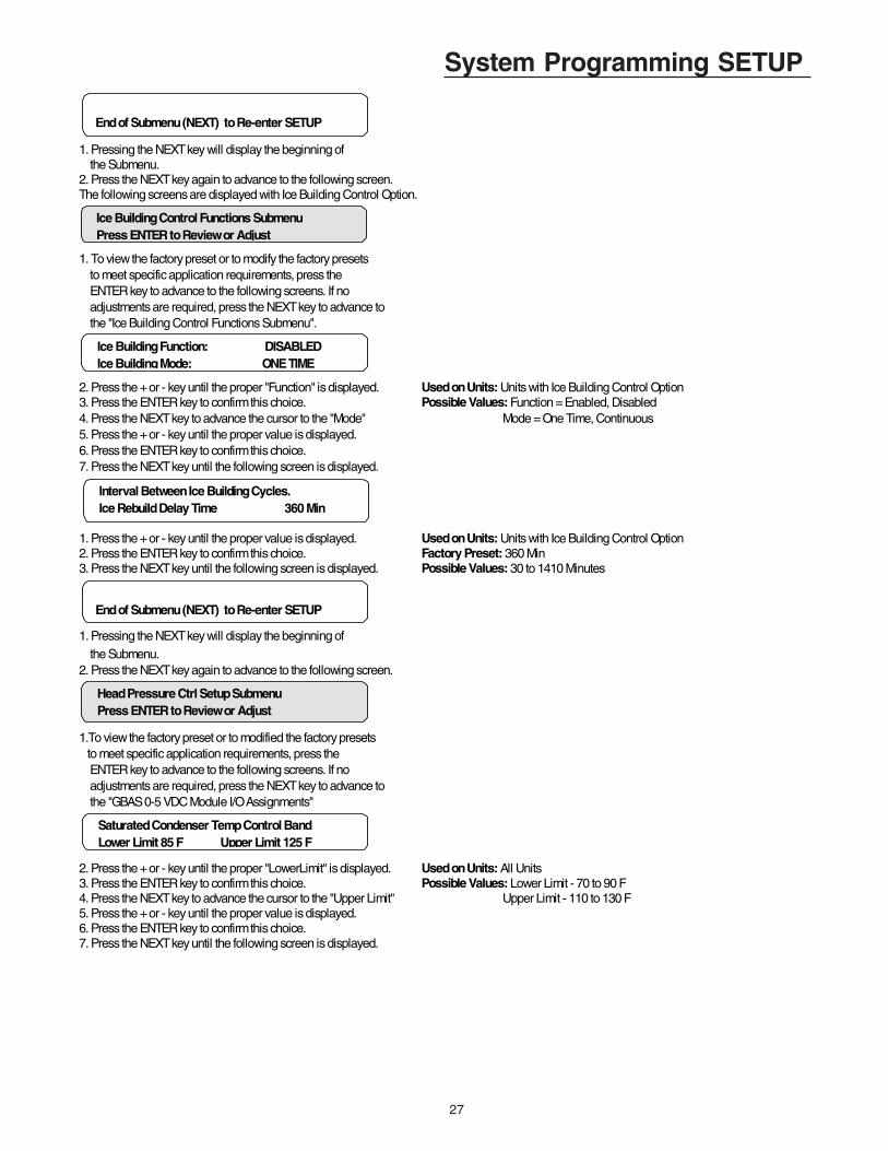
27
System Programming SETUP
1. Pressing the NEXT key will display the beginning of the Submenu.2. Press the NEXT key again to advance to the following screen.The following screens are displayed with Ice Building Control Option.
1. To view the factory preset or to modify the factory presets to meet specific application requirements, press the ENTER key to advance to the following screens. If no adjustments are required, press the NEXT key to advance to the "Ice Building Control Functions Submenu".
2. Press the + or - key until the proper "Function" is displayed. Used on Units: Units with Ice Building Control Option3. Press the ENTER key to confirm this choice. Possible Values: Function = Enabled, Disabled4. Press the NEXT key to advance the cursor to the "Mode" Mode = One Time, Continuous5. Press the + or - key until the proper value is displayed.6. Press the ENTER key to confirm this choice.7. Press the NEXT key until the following screen is displayed.
1. Press the + or - key until the proper value is displayed. Used on Units: Units with Ice Building Control Option2. Press the ENTER key to confirm this choice. Factory Preset: 360 Min3. Press the NEXT key until the following screen is displayed. Possible Values: 30 to 1410 Minutes
1. Pressing the NEXT key will display the beginning of the Submenu.2. Press the NEXT key again to advance to the following screen.
1.To view the factory preset or to modified the factory presets to meet specific application requirements, press the ENTER key to advance to the following screens. If no adjustments are required, press the NEXT key to advance to the "GBAS 0-5 VDC Module I/O Assignments"
2. Press the + or - key until the proper "LowerLimit" is displayed. Used on Units: All Units3. Press the ENTER key to confirm this choice. Possible Values: Lower Limit - 70 to 90 F4. Press the NEXT key to advance the cursor to the "Upper Limit" Upper Limit - 110 to 130 F5. Press the + or - key until the proper value is displayed.6. Press the ENTER key to confirm this choice.7. Press the NEXT key until the following screen is displayed.
Ice Building Control Functions Submenu Press ENTER to Review or Adjust
Ice Building Function: DISABLED Ice Building Mode: ONE TIME
Interval Between Ice Building Cycles. Ice Rebuild Delay Time 360 Min
End of Submenu (NEXT) to Re-enter SETUP
Head Pressure Ctrl Setup Submenu Press ENTER to Review or Adjust
Saturated Condenser Temp Control Band Lower Limit 85 F Upper Limit 125 F
End of Submenu (NEXT) to Re-enter SETUP

28
System Programming SETUPUsed on Units: All Units
Possible Values: 0 to 20 F
1. Press the + or - key until the proper value is displayed.2. Press the ENTER key to confirm this choice.3. Press the NEXT key until the following screen is displayed.
Used on Units: All UnitsPossible Values: 95 to 115 F
1. Press the + or - key until the proper value is displayed.2. Press the ENTER key to confirm this choice.3. Press the NEXT key until the following screen is displayed.
Used on Units: All UnitsPossible Values: 80 to 110 F
1. Press the + or - key until the proper value is displayed.2. Press the ENTER key to confirm this choice.3. Press the NEXT key until the following screen is displayed.
Used on Units: All UnitsPossible Values: 2.0 to 10.0 F
1. Press the + or - key until the proper value is displayed.2. Press the ENTER key to confirm this choice.3. Press the NEXT key until the following screen is displayed.
Used on Units: All UnitsPossible Values: 25 to 66 F, Disabled
1. Press the + or - key until the proper value is displayed.2. Press the ENTER key to confirm this choice.3. Press the NEXT key until the following screen is displayed.
1. Pressing the NEXT key will display the beginning of the Submenu.2. Press the NEXT key again to advance to the following screen.
This screen is displayed when GBAS 0-5 VDC Module is installed
1.To view the factory preset or to modified the factory presets to meet specific application requirements, press the ENTER key to advance to the following screens. If no adjustments are required, press the NEXT key to advance to "GBAS 0-10 VDC Module I/O Assignments"
Used on Units: With GBAS 0-5VDC ModulePossible Values: Leaving Solution Setpoint Ice Build Terminate Setpoint
2. Press the + or - key until the proper value is displayed. Hot Start Load Limit Setpoint3. Press the ENTER key to confirm this choice. Capacity Limit Setpoint4. Press the NEXT key to display Generic BAS Analog Input 2 screen. 5. Press the + or - key until the proper value is displayed.6. Press the ENTER key to confirm each choice.7. Repeat steps 1 - 4 to display Generic BAS Analog Input screens 2, 3 & 4. 8. Press the NEXT key to advance to the following screen.
Saturated Condenser Temp Control Band Temporary Low Limit Suppression 10 F
Saturated Condenser Temperature Efficiency Check Point 110 F
Saturated Condenser Temperature Low Ambient Control Point 100 F
End of Submenu (NEXT) to Re-enter STATUS
GBAS 0-5VDC Module I/O Assignment Press ENTER to Review or Adjust
GBAS (0-5VDC) Analog Input 1 Assignment NOT ASSIGNED
Saturated Condenser Temperature Low Ambient Control Deadband 4.0 F
Saturated Condenser Temperature OA Temp Supression Setpoint 40 F
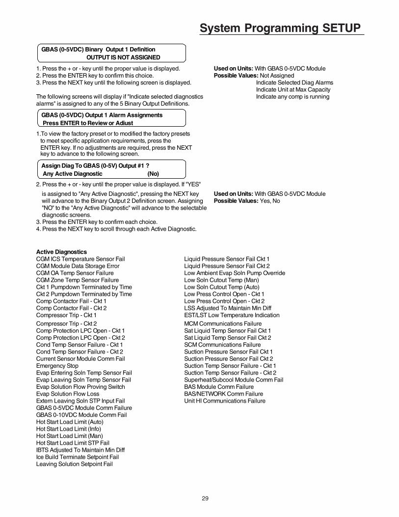
29
System Programming SETUP
1. Press the + or - key until the proper value is displayed. Used on Units: With GBAS 0-5VDC Module2. Press the ENTER key to confirm this choice. Possible Values: Not Assigned3. Press the NEXT key until the following screen is displayed. Indicate Selected Diag Alarms
Indicate Unit at Max CapacityThe following screens will display if "Indicate selected diagnostics Indicate any comp is runningalarms" is assigned to any of the 5 Binary Output Definitions.
1.To view the factory preset or to modified the factory presets to meet specific application requirements, press the ENTER key. If no adjustments are required, press the NEXT key to advance to the following screen.
2. Press the + or - key until the proper value is displayed. If "YES"
is assigned to "Any Active Diagnostic", pressing the NEXT key Used on Units: With GBAS 0-5VDC Module will advance to the Binary Output 2 Definition screen. Assigning Possible Values: Yes, No "NO" to the "Any Active Diagnostic" will advance to the selectable diagnostic screens.3. Press the ENTER key to confirm each choice.4. Press the NEXT key to scroll through each Active Diagnostic.
Active DiagnosticsCGM ICS Temperature Sensor Fail Liquid Pressure Sensor Fail Ckt 1CGM Module Data Storage Error Liquid Pressure Sensor Fail Ckt 2CGM OA Temp Sensor Failure Low Ambient Evap Soln Pump OverrideCGM Zone Temp Sensor Failure Low Soln Cutout Temp (Man)Ckt 1 Pumpdown Terminated by Time Low Soln Cutout Temp (Auto)Ckt 2 Pumpdown Terminated by Time Low Press Control Open - Ckt 1Comp Contactor Fail - Ckt 1 Low Press Control Open - Ckt 2Comp Contactor Fail - Ckt 2 LSS Adjusted To Maintain Min DiffCompressor Trip - Ckt 1 EST/LST Low Temperature IndicationCompressor Trip - Ckt 2 MCM Communications FailureComp Protection LPC Open - Ckt 1 Sat Liquid Temp Sensor Fail Ckt 1Comp Protection LPC Open - Ckt 2 Sat Liquid Temp Sensor Fail Ckt 2Cond Temp Sensor Failure - Ckt 1 SCM Communications FailureCond Temp Sensor Failure - Ckt 2 Suction Pressure Sensor Fail Ckt 1Current Sensor Module Comm Fail Suction Pressure Sensor Fail Ckt 2Emergency Stop Suction Temp Sensor Failure - Ckt 1Evap Entering Soln Temp Sensor Fail Suction Temp Sensor Failure - Ckt 2Evap Leaving Soln Temp Sensor Fail Superheat/Subcool Module Comm FailEvap Solution Flow Proving Switch BAS Module Comm FailureEvap Solution Flow Loss BAS/NETWORK Comm FailureExtern Leaving Soln STP Input Fail Unit HI Communications FailureGBAS 0-5VDC Module Comm FailureGBAS 0-10VDC Module Comm FailHot Start Load Limit (Auto)Hot Start Load Limit (Info)Hot Start Load Limit (Man)Hot Start Load Limit STP FailIBTS Adjusted To Maintain Min DiffIce Build Terminate Setpoint FailLeaving Solution Setpoint Fail
GBAS (0-5VDC) Binary Output 1 Definition OUTPUT IS NOT ASSIGNED
GBAS (0-5VDC) Output 1 Alarm Assignments Press ENTER to Review or Adjust
Assign Diag To GBAS (0-5V) Output #1 ? Any Active Diagnostic (No)
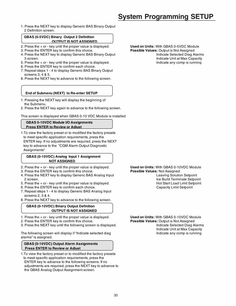
30
System Programming SETUP1. Press the NEXT key to display Generic BAS Binary Output 2 Definition screen.
2. Press the + or - key until the proper value is displayed. Used on Units: With GBAS 0-5VDC Module3. Press the ENTER key to confirm this choice. Possible Values: Output is Not Assigned4. Press the NEXT key to display Generic BAS Binary Output Indicate Selected Diag Alarms 3 screen. Indicate Unit at Max Capacity5. Press the + or - key until the proper value is displayed. Indicate any comp is running6. Press the ENTER key to confirm each choice.7. Repeat steps 1 - 4 to display Generic BAS Binary Output screens 3, 4 & 5. 8. Press the NEXT key to advance to the following screen.
1. Pressing the NEXT key will display the beginning of the Submenu.2. Press the NEXT key again to advance to the following screen.
This screen is displayed when GBAS 0-10 VDC Module is installed
1.To view the factory preset or to modified the factory presets to meet specific application requirements, press the ENTER key. If no adjustments are required, press the NEXT key to advance to the "CGM Alarm Output Diagnostic Assignments"
2. Press the + or - key until the proper value is displayed. Used on Units: With GBAS 0-10VDC Module3. Press the ENTER key to confirm this choice. Possible Values: Not Assigned4. Press the NEXT key to display Generic BAS Analog Input Leaving Solution Setpoint 2 screen. Ice Build Terminate Setpoint5. Press the + or - key until the proper value is displayed. Hot Start Load Limit Setpoint6. Press the ENTER key to confirm each choice. Capacity Limit Setpoint7. Repeat steps 1 - 4 to display Generic BAS Analog Input screens 2, 3 & 4. 8. Press the NEXT key to advance to the following screen.
1. Press the + or - key until the proper value is displayed. Used on Units: With GBAS 0-10VDC Module2. Press the ENTER key to confirm this choice. Possible Values: Output is Not Assigned3. Press the NEXT key until the following screen is displayed. Indicate Selected Diag Alarms
Indicate Unit at Max CapacityThe following screen will display if "Indicate selected diag Indicate any comp is runningalarms" is assigned.
1.To view the factory preset or to modified the factory presets to meet specific application requirements, press the ENTER key to advance to the following screens. If no adjustments are required, press the NEXT key to advance to the GBAS Analog Output Assignment screen.
End of Submenu (NEXT) to Re-enter SETUP
GBAS 0-10VDC Module I/O AssignmentsPress ENTER to Review or Adjust
GBAS (0-10VDC) Analog Input 1 Assignment NOT ASSIGNED
GBAS (0-10VDC) Binary Output Definition OUTPUT IS NOT ASSIGNED
GBAS (0-5VDC) Binary Output 2 DefinitionOUTPUT IS NOT ASSIGNED
GBAS (0-10VDC) Output Alarm Assignments Press ENTER to Review or Adjust
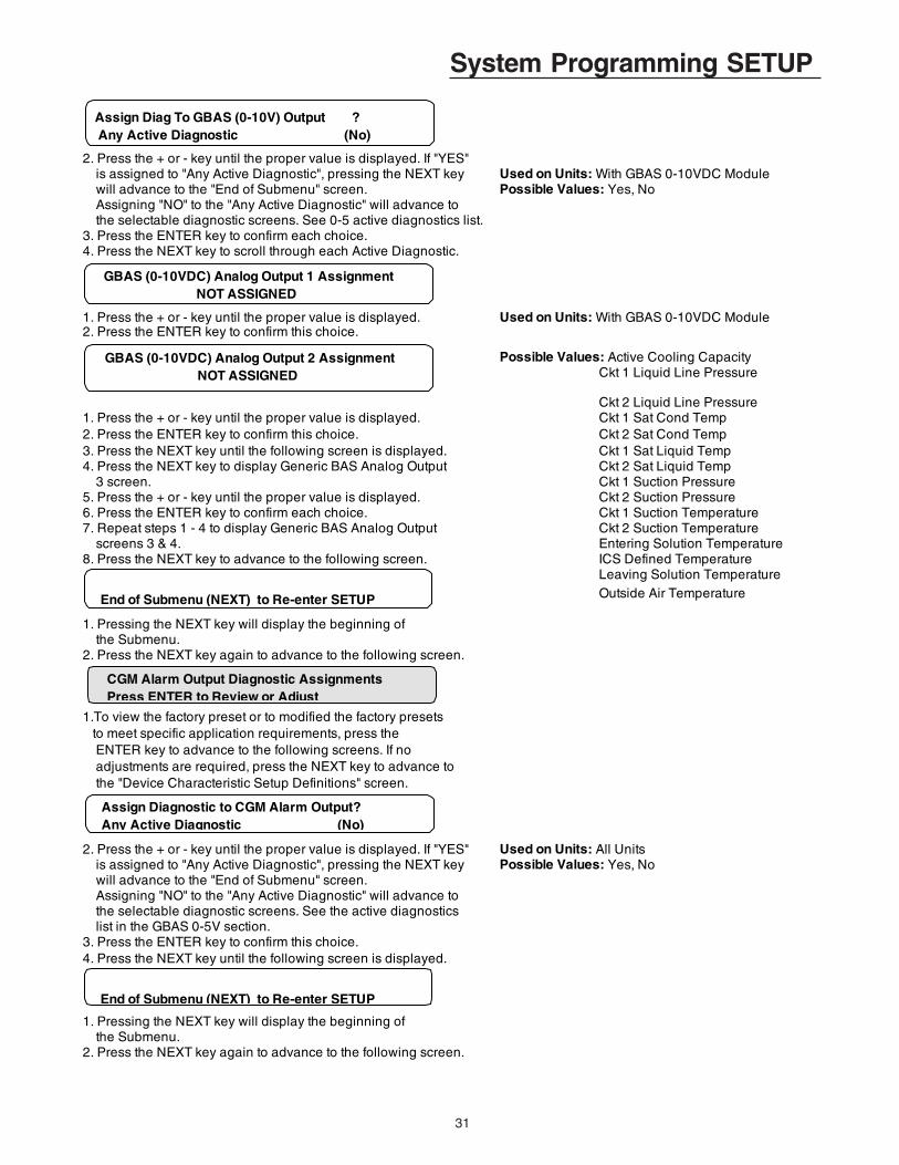
31
System Programming SETUP
2. Press the + or - key until the proper value is displayed. If "YES" is assigned to "Any Active Diagnostic", pressing the NEXT key Used on Units: With GBAS 0-10VDC Module will advance to the "End of Submenu" screen. Possible Values: Yes, No Assigning "NO" to the "Any Active Diagnostic" will advance to the selectable diagnostic screens. See 0-5 active diagnostics list.3. Press the ENTER key to confirm each choice.4. Press the NEXT key to scroll through each Active Diagnostic.
1. Press the + or - key until the proper value is displayed. Used on Units: With GBAS 0-10VDC Module2. Press the ENTER key to confirm this choice.
Possible Values: Active Cooling Capacity Ckt 1 Liquid Line Pressure
Ckt 2 Liquid Line Pressure1. Press the + or - key until the proper value is displayed. Ckt 1 Sat Cond Temp2. Press the ENTER key to confirm this choice. Ckt 2 Sat Cond Temp3. Press the NEXT key until the following screen is displayed. Ckt 1 Sat Liquid Temp4. Press the NEXT key to display Generic BAS Analog Output Ckt 2 Sat Liquid Temp 3 screen. Ckt 1 Suction Pressure5. Press the + or - key until the proper value is displayed. Ckt 2 Suction Pressure6. Press the ENTER key to confirm each choice. Ckt 1 Suction Temperature7. Repeat steps 1 - 4 to display Generic BAS Analog Output Ckt 2 Suction Temperature screens 3 & 4. Entering Solution Temperature8. Press the NEXT key to advance to the following screen. ICS Defined Temperature
Leaving Solution Temperature Outside Air Temperature
1. Pressing the NEXT key will display the beginning of the Submenu.2. Press the NEXT key again to advance to the following screen.
1.To view the factory preset or to modified the factory presets to meet specific application requirements, press the ENTER key to advance to the following screens. If no adjustments are required, press the NEXT key to advance to the "Device Characteristic Setup Definitions" screen.
2. Press the + or - key until the proper value is displayed. If "YES" Used on Units: All Units is assigned to "Any Active Diagnostic", pressing the NEXT key Possible Values: Yes, No will advance to the "End of Submenu" screen. Assigning "NO" to the "Any Active Diagnostic" will advance to the selectable diagnostic screens. See the active diagnostics list in the GBAS 0-5V section.3. Press the ENTER key to confirm this choice.4. Press the NEXT key until the following screen is displayed.
1. Pressing the NEXT key will display the beginning of the Submenu.2. Press the NEXT key again to advance to the following screen.
End of Submenu (NEXT) to Re-enter SETUP
CGM Alarm Output Diagnostic AssignmentsPress ENTER to Review or Adjust
Assign Diagnostic to CGM Alarm Output? Any Active Diagnostic (No)
End of Submenu (NEXT) to Re-enter SETUP
GBAS (0-10VDC) Analog Output 1 Assignment NOT ASSIGNED
Assign Diag To GBAS (0-10V) Output ? Any Active Diagnostic (No)
GBAS (0-10VDC) Analog Output 2 Assignment NOT ASSIGNED
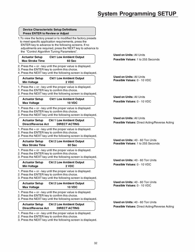
32
System Programming SETUP
1.To view the factory preset or to modified the factory presets to meet specific application requirements, press the ENTER key to advance to the following screens. If no adjustments are required, press the NEXT key to advance to the "Control Algorithm Tuning Parameters".
Used on Units: All Units
Possible Values: 1 to 255 Seconds
2. Press the + or - key until the proper value is displayed.3. Press the ENTER key to confirm this choice.4. Press the NEXT key until the following screen is displayed.
Used on Units: All UnitsPossible Values: 0 - 10 VDC
1. Press the + or - key until the proper value is displayed.2. Press the ENTER key to confirm this choice.3. Press the NEXT key until the following screen is displayed.
Used on Units: All Units
Possible Values: 0 - 10 VDC
1. Press the + or - key until the proper value is displayed.2. Press the ENTER key to confirm this choice.3. Press the NEXT key until the following screen is displayed.
Used on Units: All Units
Possible Values: Direct Acting/Reverse Acting
1. Press the + or - key until the proper value is displayed.2. Press the ENTER key to confirm this choice.3. Press the NEXT key until the following screen is displayed.
Used on Units: 40 - 60 Ton UnitsPossible Values: 1 to 255 Seconds
1. Press the + or - key until the proper value is displayed.2. Press the ENTER key to confirm this choice.3. Press the NEXT key until the following screen is displayed.
Used on Units: 40 - 60 Ton Units
Possible Values: 0 - 10 VDC
1. Press the + or - key until the proper value is displayed.2. Press the ENTER key to confirm this choice.3. Press the NEXT key until the following screen is displayed.
Used on Units: 40 - 60 Ton UnitsPossible Values: 0 - 10 VDC
1. Press the + or - key until the proper value is displayed.2. Press the ENTER key to confirm this choice.3. Press the NEXT key until the following screen is displayed.
Used on Units: 40 - 60 Ton Units
Possible Values: Direct Acting/Reverse Acting
1. Press the + or - key until the proper value is displayed.2. Press the ENTER key to confirm this choice.3. Press the NEXT key until the following screen is displayed.
Device Characteristic Setup Definitions Press ENTER to Review or Adjust
Actuator Setup Ckt1 Low Ambient Output Max Stroke Time 60 Sec
Actuator Setup Ckt1 Low Ambient Output Min Voltage 2 VDC
Actuator Setup Ckt1 Low Ambient Output Max Voltage 10 VDC
Actuator Setup Ckt 1 Low Ambient Output Direct/Reverse Act DIRECT ACTING
Actuator Setup Ckt 2 Low Ambient Output Max Stroke Time 60 Sec
Actuator Setup Ckt 2 Low Ambient Output Min Voltage 2 VDC
Actuator Setup Ckt 2 Low Ambient Output Max Voltage 10 VDC
Actuator Setup Ckt 2 Low Ambient Output Direct/Reverse Act DIRECT ACTING

33
System Programming SETUPUsed on Units: With Superheat/Subcooling OptionPossible Values: 0 PSIG - 0.000 to 4.000 VDC 100 PSIG - 1.000 to 5.000 VDC
1. Press the + or - key until the proper value is displayed.2. Press the ENTER key to confirm this choice.3. Press the NEXT key to advance the cursor to the "100 PSIG"4. Press the + or - key until the proper value is displayed.5. Press the ENTER key to confirm this choice.6. Press the NEXT key until the following screen is displayed.
Used on Units: With Superheat/Subcooling OptionPossible Values: 0 PSIG - 0.000 to 4.000 VDC 400 PSIG - 1.000 to 5.000 VDC
1. Press the + or - key until the proper value is displayed.2. Press the ENTER key to confirm this choice.3. Press the NEXT key to advance the cursor to the "400 PSIG"4. Press the + or - key until the proper value is displayed.5. Press the ENTER key to confirm this choice.6. Press the NEXT key until the following screen is displayed.
Used on Units: 40-60 Ton With Superheat/SubcoolingPossible Values: 0 PSIG - 0.000 to 4.000 VDC 100 PSIG - 1.000 to 5.000 VDC
1. Press the + or - key until the proper value is displayed.2. Press the ENTER key to confirm this choice.3. Press the NEXT key to advance the cursor to the "100 PSIG"4. Press the + or - key until the proper value is displayed.5. Press the ENTER key to confirm this choice.6. Press the NEXT key until the following screen is displayed.
Used on Units: 40-60 Ton With Superheat/SubcoolingPossible Values: 0 PSIG - 0.000 to 4.000 VDC 400 PSIG - 1.000 to 5.000 VDC
1. Press the + or - key until the proper value is displayed.2. Press the ENTER key to confirm this choice.3. Press the NEXT key to advance the cursor to the "400 PSIG"4. Press the + or - key until the proper value is displayed.5. Press the ENTER key to confirm this choice.6. Press the NEXT key until the following screen is displayed.
1. Pressing the NEXT key will display the beginning of the Submenu.2. Press the NEXT key again to advance to the following screen.
1.To view the factory preset or to modified the factory presets to meet specific application requirements, press the ENTER key to advance to the following screens. If no adjustments are required, press the NEXT key to advance to the beginning of the "Setup" menu.
Used on Units: All UnitsPossible Values: 4.0 to 20.0 F
2. Press the + or - key until the proper value is displayed.3. Press the ENTER key to confirm this choice.4. Press the NEXT key until the following screen is displayed.
End of Submenu (NEXT) to Re-enter STATUS
Control Algorithm Tuning Parameters Press ENTER to Review or Adjust
Comfort Cooling Design Delta Temperature Setpoint 10.0 F
Ckt 1 Suction Line Pressure Transducer 0 PSIG= 0.118 VDC 100 PSIG= 4.847 VDC
Ckt 1 Liquid Line Pressure Transducer 0 PSIG= 0.118 VDC 400 PSIG= 4.847 VDC
Ckt 2 Suction Line Pressure Transducer 0 PSIG= 0.118 VDC 100 PSIG= 4.847 VDC
Ckt 2 Liquid Line Pressure Transducer 0 PSIG= 0.118 VDC 400 PSIG= 4.847 VDC

34
System Programming SETUP ENTER key to advance to the following screens. If no adjustments are required, press the NEXT key to advance to the beginning of the "Setup" menu.
Used on Units: All Units
Possible Values: 4.0 to 20.0 F
2. Press the + or - key until the proper value is displayed.3. Press the ENTER key to confirm this choice.4. Press the NEXT key until the following screen is displayed.
Used on Units: All Units
Possible Values: 1 to 128
1. Press the + or - key until the proper value is displayed.2. Press the ENTER key to confirm this choice.3. Press the NEXT key until the following screen is displayed.
Used on Units: All Units
Possible Values: Proportional 2.0 to 200.0 Reset Time 30 to 3600 Sec
1. Press the + or - key until the proper value is displayed.2. Press the ENTER key to confirm this choice.3. Press the NEXT key to advance the cursor to the "Reset Time"4. Press the + or - key until the proper value is displayed.5. Press the ENTER key to confirm this choice.6. Press the NEXT key until the following screen is displayed.
Used on Units: All Units
Possible Values: Proport Bias 0 to 400% Max Cy Rate - 1.5 to 20.0 cph
1. Press the + or - key until the proper value is displayed.2. Press the ENTER key to confirm this choice.3. Press the NEXT key to advance the cursor to the "Max Cy Rate".4. Press the + or - key until the proper value is displayed.5. Press the ENTER key to confirm this choice.6. Press the NEXT key until the following screen is displayed.
Used on Units: All Units
Possible Values: Proportional 0.2 to 20.0 Reset Time 5 to 600 Sec
1. Press the + or - key until the proper value is displayed.2. Press the ENTER key to confirm this choice.3. Press the NEXT key to advance the cursor to the "Reset Time"4. Press the + or - key until the proper value is displayed.5. Press the ENTER key to confirm this choice.6. Press the NEXT key until the following screen is displayed.
Used on Units: All UnitsPossible Values: 0 to 50
1. Press the + or - key until the proper value is displayed.
Comfort Cooling Design Delta Temperature Setpoint 10.0 F
Comfort Cooling Control Response Setpoint 25
Process Cooling Control Gains Proportional 25 %/F Reset Time 90s
Process Cooling Control Gains Proport Bias 0% Max Cy Rate 15.0 cph
Low Ambient Fan Control Gain Proportional 2.0 %/F Reset Time 90 Sec
Low Ambient Fan Control Gain Rate Time 0 Sec

35
SETPOINTS Menu
The SETPOINTS menu is used to designate defaultsetpoints, low ambient compressor lockout setpoints andselect setpoint sources.
These setpoints will be active (in use) for the "SetpointSource Selection" designated as "DEFAULT" for these in-puts.
System Programming SETPOINTSWhen a setpoint screen is displayed for 30 minutes withouta key being pressed, the LCD screen will revert to the gen-eral operating status display. If this happens, press theSETPOINT key again to return to the setpoint menu.
Used on Units: All UnitsPossible Values: Based on Configured Leaving Solution STP Range: Range 51.0 - 65.0°F
1. Press the + or - key until the proper value is displayed. Range 40.0 - 50.0°F2. Press the ENTER key to confirm this choice. Range 30.0 - 39.0°F3. Press the NEXT key until the following screen is displayed. Range 20.0 - 29.0°F
Range 10.0 - 75.0°F (SPECIAL)Used on Units: Units with Ice Building Control OptionPossible Values: 20.0 to 31.0 F
1. Press the + or - key until the proper value is displayed.2. Press the ENTER key to confirm this choice.3. Press the NEXT key until the following screen is displayed.
Used on Units: All UnitsPossible Values: -10.0 to 60.0 FNote: Maximum setting may be limited by ’Hi Leaving
1. Press the + or - key until the proper value is displayed. Solution Setpoint’2. Press the ENTER key to confirm this choice.3. Press the NEXT key until the following screen is displayed.
Used on Units: All Brazed Plate UnitsPossible Values: 0 to 45.0 FNote: Maximum setting may be limited by ’Hi Leaving
1. Press the + or - key until the proper value is displayed. Solution Setpoint’2. Press the ENTER key to confirm this choice.3. Press the NEXT key until the following screen is displayed.
Used on Units: All UnitsPossible Values: 60.0 to 80.0 F
1. Press the + or - key until the proper value is displayed.2. Press the ENTER key to confirm this choice.3. Press the NEXT key until the following screen is displayed.
Used on Units: All UnitsPossible Values: -20.0 to 50.0 F
1. Press the + or - key until the proper value is displayed.2. Press the ENTER key to confirm this choice.3. Press the NEXT key until the following screen is displayed.
Used on Units: All UnitsPossible Values: -20.0 to 60.0 F
1. Press the + or - key until the proper value is displayed.2. Press the ENTER key to confirm this choice.3. Press the NEXT key until the following screen is displayed.
Used on Units: All UnitsPossible Values: Human Interface STP Menu GBAS 0-5VDC Module
1. Press the + or - key until the proper value is displayed. GBAS 0-10VDC Module2. Press the ENTER key to confirm this choice. Ext Leaving Soln STP Input
Stop Ice Making When Ent Soln Temp Below Hi Ice Build Terminate Setpoint: 27.0 F
Comp(s) OFF if Solution Temp Below Low Solution Cutout Temp: 35.0 F
HI Hot Start Load Limit Setpoint: 71.0 F
Request Pump ON When OA Temp Less Than Low Ambient Pump Override Temp: 35 F
Low Ambient Comp Lockout Temp: 40 F Comp(s) OFF if OA Temp Below This Value
Use Leaving Solution Setpoint From: HUMAN INTERFACE STP MENU
Heat Output ON When EST or LST Less Than Heat Tape Temperature Setpoint: 40.0 F
HI Leaving Solution Setpoint: 44 F
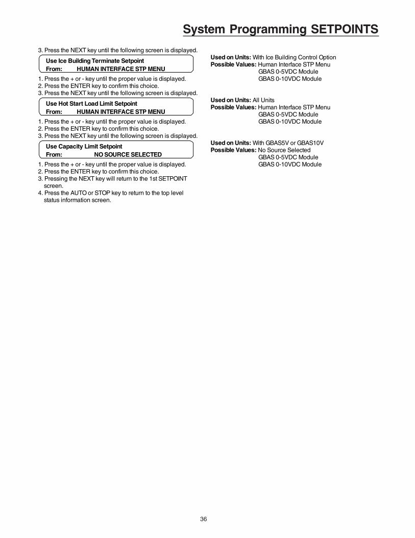
36
System Programming SETPOINTS
3. Press the NEXT key until the following screen is displayed. Used on Units: With Ice Building Control OptionPossible Values: Human Interface STP Menu GBAS 0-5VDC Module
1. Press the + or - key until the proper value is displayed. GBAS 0-10VDC Module2. Press the ENTER key to confirm this choice.3. Press the NEXT key until the following screen is displayed.
Used on Units: All UnitsPossible Values: Human Interface STP Menu GBAS 0-5VDC Module
1. Press the + or - key until the proper value is displayed. GBAS 0-10VDC Module2. Press the ENTER key to confirm this choice.3. Press the NEXT key until the following screen is displayed.
Used on Units: With GBAS5V or GBAS10VPossible Values: No Source Selected GBAS 0-5VDC Module
1. Press the + or - key until the proper value is displayed. GBAS 0-10VDC Module2. Press the ENTER key to confirm this choice.3. Pressing the NEXT key will return to the 1st SETPOINT screen. 4. Press the AUTO or STOP key to return to the top level status information screen.
Use Ice Building Terminate Setpoint From: HUMAN INTERFACE STP MENU
Use Hot Start Load Limit Setpoint From: HUMAN INTERFACE STP MENU
Use Capacity Limit Setpoint From: NO SOURCE SELECTED

37
System ConfigurationCONFIGURATION Menu
The CGM controlled unit has many operating functionswhose settings are preset at the factory. The following con-figuration programming steps are provided for those caseswhere the Human Interface module has been replaced afterthe unit has been in operation and must be reconfigured.
Refer to the Model number stamped on the unit nameplatelocated on the control panel door while scrolling through theconfiguraton screes. Certain digits of this alpha/numericmodel number provide information that must be entered atthe Human Interface (HI) in order for the CGM network tooperate properly.
Press the CONFIGURATION key to display the followingscreens. Check the unit model number and compare it to thedata that is displayed in the following screens
Used on Units: All UnitsPossible Values: 20, 25, 30, 40, 50, 60
1. Press the + or - key until the proper value is displayed.2. Press the ENTER key to confirm this choice.3. Press the NEXT key until the following screen is displayed.
Used on Units: All UnitsPossible Values: 200 VAC, 230 VAC, 380 VAC, 415 VAC, 460 VAC, 575 VAC,
1. Press the + or - key until the proper value is displayed. Special Voltage2. Press the ENTER key to confirm this choice.3. Press the NEXT key until the following screen is displayed.
Used on Units: All UnitsPossible Values: Installed, Not Installed
1. Press the + or - key until the proper value is displayed.2. Press the ENTER key to confirm this choice.3. Press the NEXT key until the following screen is displayed.
Used on Units: All UnitsPossible Values: 51-65 F, 40-50 F, 30-39 F, 20-29 F, Special
1. Press the + or - key until the proper value is displayed.2. Press the ENTER key to confirm this choice.3. Press the NEXT key until the following screen is displayed.
Used on Units: All UnitsPossible Values: Installed, Not Installed
1. Press the + or - key until the proper value is displayed.2. Press the ENTER key to confirm this choice.3. Press the NEXT key until the following screen is displayed.
Used on Units: All UnitsPossible Values: Installed, Not Installed
1. Press the + or - key until the proper value is displayed.2. Press the ENTER key to confirm this choice.3. Press the NEXT key until the following screen is displayed.
Used on Units: All UnitsPossible Values: Installed, Not Installed
1. Press the + or - key until the proper value is displayed.2. Press the ENTER key to confirm this choice.3. Press the NEXT key until the following screen is displayed.
Used on Units: All UnitsPossible Values: Installed, Not Installed
1. Press the + or - key until the proper value is displayed.2. Press the ENTER key to confirm this choice.
Configuration - Model Num Digit 5,6,7 Unit Capacity 50
Configuration - Model Num Digit 8 Line Voltage 460 VAC
Configuration - Model Num Digit 11 Ice Building Control INSTALLED
Configuration - Model Num Digit 11 Leaving Solution STP Range 40 - 50 F
Configuration - Model Num Digit 13+ Hot Gas Bypass Option INSTALLED
Configuration - Model Num Digit 13+GBAS 0-5VDC Module INSTALLED
Configuration - Model Num Digit 13+ GBAS 0-10VDC Module INSTALLED
Configuration - Model Num Digit 13+Superheat/Subcool Module INSTALLED

38
System Configuration3. Press the NEXT key until the following screen is displayed.
Used on Units: All UnitsPossible Values: Installed, Not Installed
1. Press the + or - key until the proper value is displayed.2. Press the ENTER key to confirm this choice.3. Press the NEXT key until the following screen is displayed.
Used on Units: All UnitsPossible Values: Installed, Not Installed
1. Press the + or - key until the proper value is displayed.2. Press the ENTER key to confirm this choice.3. Press the NEXT key until the following screen is displayed.
Used on Units: All UnitsPossible Values: Installed, Not Installed
1. Press the + or - key until the proper value is displayed.2. Press the ENTER key to confirm this choice.3. Press the NEXT key until the following screen is displayed.
The following displays are not editable.Used on Units: All UnitsPossible Values: 1.0 or Greater
1. Press the NEXT key until one of the following screens is displayed. Used on Units: 20 to 30 Ton UnitsPossible Values: 1.0 or Greater
ORUsed on Units: 40 to 60 Ton UnitsPossible Values: 1.0 or Greater
1. Press the NEXT key until the following screen is displayed. Used on Units: With GBAS 5VDC ModulePossible Values: 1.0 or Greater
1. Press the NEXT key until the following screen is displayed. Used on Units: With GBAS 10VDC ModulePossible Values: 1.0 or Greater
1. Press the NEXT key until the following screen is displayed. Used on Units: With SSM ModulePossible Values: 1.0 or Greater
Configuration - Model Num Digit 13+ Current Sensing Module INSTALLED
Configuration - Model Num Digit 13+ BAS Communications Module INSTALLED
Configuration - Model Num Digit 13+ Remote Human Interface INSTALLED
Software Revision Number Report: Cold Generator Module (CGM) 1.00
Software Revision Number Report: Multiple Compressor Module (MCM) 1.00
Software Revision Number Report: GBAS 0-5VDC Module 1.00
Software Revision Number Report: GBAS 0-10VDC Module 1.00
Software Revision Number Report: Superheat/Subcool Module (SSM) 1.00
Software Revision Number Report: Single Compressor Module (SCM) 1.00
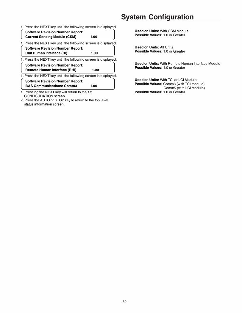
39
System Configuration1. Press the NEXT key until the following screen is displayed.
Used on Units: With CSM ModulePossible Values: 1.0 or Greater
1. Press the NEXT key until the following screen is displayed. Used on Units: All UnitsPossible Values: 1.0 or Greater
1. Press the NEXT key until the following screen is displayed. Used on Units: With Remote Human Interface ModulePossible Values: 1.0 or Greater
1. Press the NEXT key until the following screen is displayed. Used on Units: With TCI or LCI ModulePossible Values: Comm3 (with TCI module) Comm5 (with LCI module)
1. Pressing the NEXT key will return to the 1st Possible Values: 1.0 or Greater CONFIGURATION screen. 2. Press the AUTO or STOP key to return to the top level status information screen.
Software Revision Number Report: Current Sensing Module (CSM) 1.00
Software Revision Number Report: Unit Human Interface (HI) 1.00
Software Revision Number Report: BAS Communications: Comm3 1.00
Software Revision Number Report: Remote Human Interface (RHI) 1.00
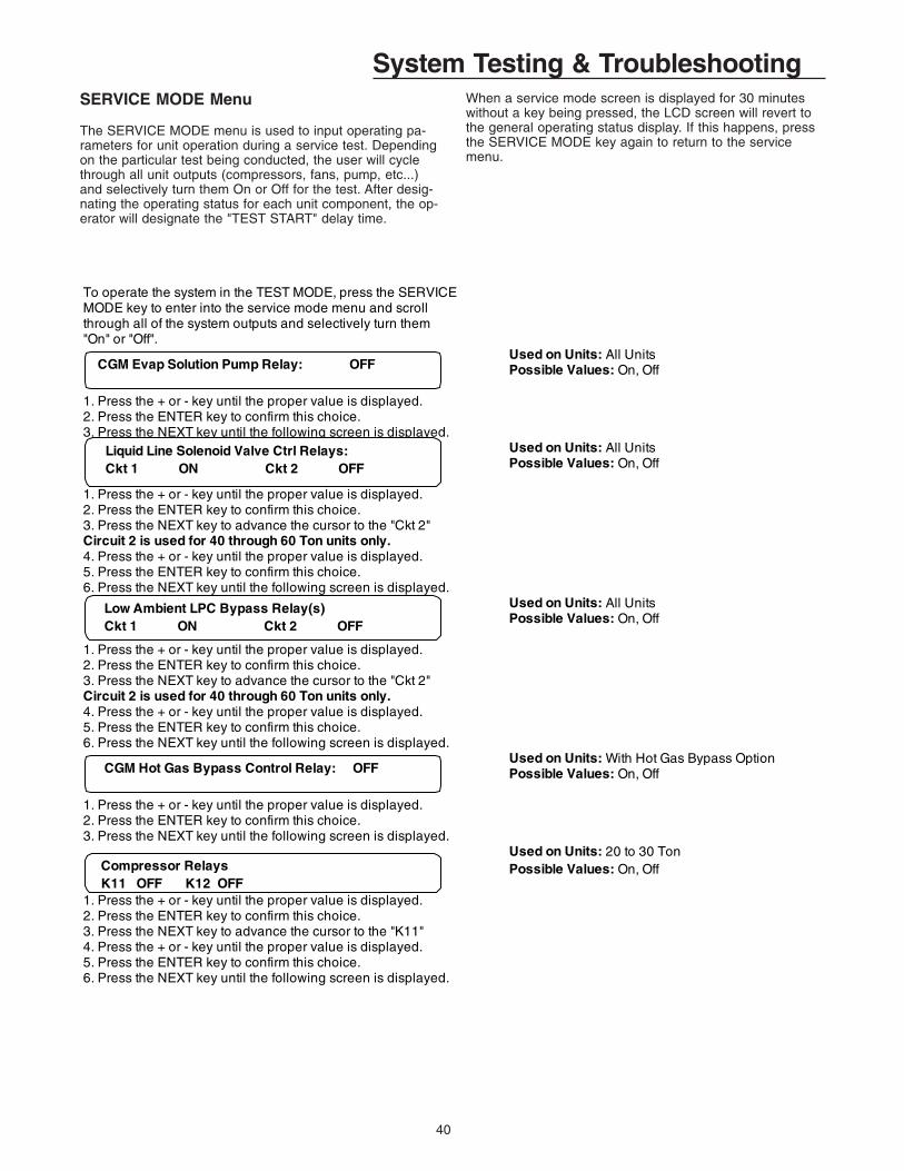
40
System Testing & Troubleshooting
To operate the system in the TEST MODE, press the SERVICEMODE key to enter into the service mode menu and scroll through all of the system outputs and selectively turn them"On" or "Off".
Used on Units: All UnitsPossible Values: On, Off
1. Press the + or - key until the proper value is displayed.2. Press the ENTER key to confirm this choice.3. Press the NEXT key until the following screen is displayed.
Used on Units: All UnitsPossible Values: On, Off
1. Press the + or - key until the proper value is displayed.2. Press the ENTER key to confirm this choice.3. Press the NEXT key to advance the cursor to the "Ckt 2"Circuit 2 is used for 40 through 60 Ton units only.4. Press the + or - key until the proper value is displayed.5. Press the ENTER key to confirm this choice.6. Press the NEXT key until the following screen is displayed.
Used on Units: With Hot Gas Bypass OptionPossible Values: On, Off
1. Press the + or - key until the proper value is displayed.2. Press the ENTER key to confirm this choice.3. Press the NEXT key until the following screen is displayed.
Used on Units: 20 to 30 TonPossible Values: On, Off
1. Press the + or - key until the proper value is displayed.2. Press the ENTER key to confirm this choice.3. Press the NEXT key to advance the cursor to the "K11"4. Press the + or - key until the proper value is displayed.5. Press the ENTER key to confirm this choice.6. Press the NEXT key until the following screen is displayed.
CGM Evap Solution Pump Relay: OFF
Liquid Line Solenoid Valve Ctrl Relays: Ckt 1 ON Ckt 2 OFF
CGM Hot Gas Bypass Control Relay: OFF
Low Ambient LPC Bypass Relay(s) Ckt 1 ON Ckt 2 OFF
Compressor Relays K11 OFF K12 OFF
SERVICE MODE Menu
The SERVICE MODE menu is used to input operating pa-rameters for unit operation during a service test. Dependingon the particular test being conducted, the user will cyclethrough all unit outputs (compressors, fans, pump, etc...)and selectively turn them On or Off for the test. After desig-nating the operating status for each unit component, the op-erator will designate the "TEST START" delay time.
When a service mode screen is displayed for 30 minuteswithout a key being pressed, the LCD screen will revert tothe general operating status display. If this happens, pressthe SERVICE MODE key again to return to the servicemenu.

41
System Testing & TroubleshootingOR
The following screen will display on 40 to 60 Ton units.Used on Units: 40 to 60 TonPossible Values: On, Off
1. Press the + or - key until the proper value is displayed.2. Press the ENTER key to confirm this choice.3. Press the NEXT key to advance the cursor to the "K12"4. Press the + or - key until the proper value is displayed.5. Press the ENTER key to confirm this choice.6. Press the NEXT key to advance the cursor to the "K3"7. Press the + or - key until the proper value is displayed.8. Press the ENTER key to confirm this choice.9. Press the NEXT key to advance the cursor to the "K4"10. Press the + or - key until the proper value is displayed.11. Press the ENTER key to confirm this choice.12. Press the NEXT key until the following screen is displayed.
Used on Units: All UnitsPossible Values: On, Off, Auto
1. Press the + or - key until the proper value is displayed.2. Press the ENTER key to confirm this choice.3. Press the NEXT key to advance the cursor to the "1B"4. Press the + or - key until the proper value is displayed.5. Press the ENTER key to confirm this choice.6. Press the NEXT key until the following screen is displayed.7. Press the + or - key until the proper value is displayed.8. Press the ENTER key to confirm this choice.9. Press the NEXT key to advance the cursor to the "2B"
The following screen will display on 40 to 60 Ton units.Used on Units: 40 to 60 TonPossible Values: On, Off, Auto
1. Press the + or - key until the proper value is displayed.2. Press the ENTER key to confirm this choice.3. Press the NEXT key to advance the cursor to the "1B"4. Press the + or - key until the proper value is displayed.5. Press the ENTER key to confirm this choice.6. Press the NEXT key to advance the cursor to the "2A"7. Press the + or - key until the proper value is displayed.8. Press the ENTER key to confirm this choice.9. Press the NEXT key to advance the cursor to the "2B"
Used on Units: All UnitsPossible Values: Auto, 0 to 100%Note: This is the low ambient damper position
1. Press the + or - key until the proper value is displayed.2. Press the ENTER key to confirm this choice.Circuit 2 is used for 40 through 60 Ton units only.3. Press the NEXT key to advance the cursor to the "Ckt 2"4. Press the + or - key until the proper value is displayed.5. Press the ENTER key to confirm this choice.6. Press the NEXT key until the following screen is displayed.
Used on Units: All Brazed Plate UnitsPossible Values: On, Off
1. Press the + or - key until the proper value is displayed.2. Press the ENTER key to confirm this choice.3. Press the NEXT key until the following screen is displayed.
1. Press the + or - key until the proper value is displayed.2. Press the ENTER key to confirm this choice.3. Press the NEXT key until the following screen is displayed.
Compressor Relays K11 OFF K12 OFF K3 OFF K4 OFF
Condenser Fan Outputs 2A OFF 2B OFF 2C OFF
Condenser Fan SpeedCkt 1 0 % Ckt 2 0%
CGM Alarm Output: OFF
Condenser Fan Outputs 1A OFF 1B OFF 1C OFF
MCM Heater Tape Relay K13: OFF Relay ON: Heat Off, Relay OFF: Heat On
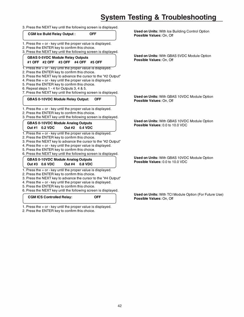
42
System Testing & Troubleshooting3. Press the NEXT key until the following screen is displayed.
Used on Units: With Ice Building Control OptionPossible Values: On, Off
1. Press the + or - key until the proper value is displayed.2. Press the ENTER key to confirm this choice.3. Press the NEXT key until the following screen is displayed.
Used on Units: With GBAS 5VDC Module OptionPossible Values: On, Off
1. Press the + or - key until the proper value is displayed.2. Press the ENTER key to confirm this choice.3. Press the NEXT key to advance the cursor to the "#2 Output"4. Press the + or - key until the proper value is displayed.5. Press the ENTER key to confirm this choice.6. Repeat steps 1 - 4 for Outputs 3, 4 & 5.7. Press the NEXT key until the following screen is displayed.
Used on Units: With GBAS 10VDC Module OptionPossible Values: On, Off
1. Press the + or - key until the proper value is displayed.2. Press the ENTER key to confirm this choice.3. Press the NEXT key until the following screen is displayed.
Used on Units: With GBAS 10VDC Module OptionPossible Values: 0.0 to 10.0 VDC
1. Press the + or - key until the proper value is displayed.2. Press the ENTER key to confirm this choice.3. Press the NEXT key to advance the cursor to the "#2 Output"4. Press the + or - key until the proper value is displayed.5. Press the ENTER key to confirm this choice.6. Press the NEXT key until the following screen is displayed.
Used on Units: With GBAS 10VDC Module OptionPossible Values: 0.0 to 10.0 VDC
1. Press the + or - key until the proper value is displayed.2. Press the ENTER key to confirm this choice.3. Press the NEXT key to advance the cursor to the "#4 Output"4. Press the + or - key until the proper value is displayed.5. Press the ENTER key to confirm this choice.6. Press the NEXT key until the following screen is displayed.
Used on Units: With TCI Module Option (For Future Use)Possible Values: On, Off
1. Press the + or - key until the proper value is displayed.2. Press the ENTER key to confirm this choice.
CGM Ice Build Relay Output : OFF
GBAS 0-5VDC Module Relay Outputs #1 OFF #2 OFF #3 OFF #4 OFF #5 OFF
GBAS 0-10VDC Module Relay Output: OFF
GBAS 0-10VDC Module Analog Outputs Out #1 0.2 VDC Out #2 0.4 VDC
GBAS 0-10VDC Module Analog Outputs Out #3 0.6 VDC Out #4 0.8 VDC
CGM ICS Controlled Relay: OFF
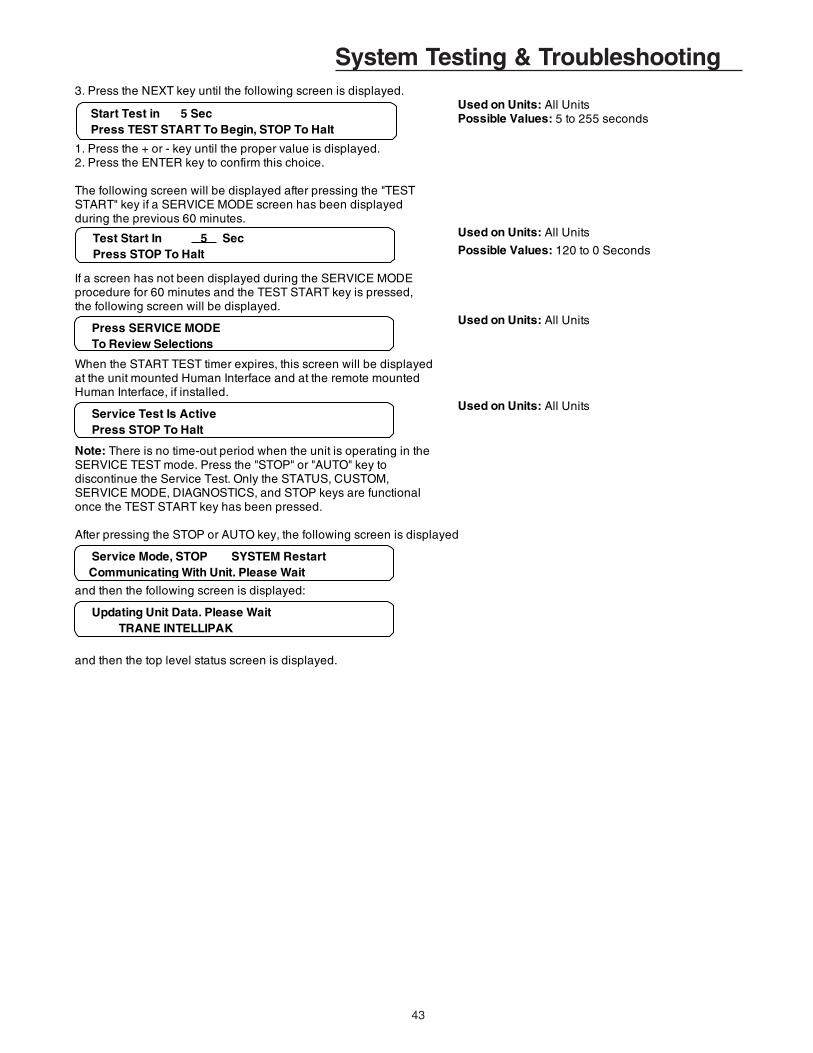
43
System Testing & Troubleshooting3. Press the NEXT key until the following screen is displayed.
Used on Units: All UnitsPossible Values: 5 to 255 seconds
1. Press the + or - key until the proper value is displayed.2. Press the ENTER key to confirm this choice.
The following screen will be displayed after pressing the "TESTSTART" key if a SERVICE MODE screen has been displayedduring the previous 60 minutes.
Used on Units: All Units
Possible Values: 120 to 0 Seconds
If a screen has not been displayed during the SERVICE MODEprocedure for 60 minutes and the TEST START key is pressed, the following screen will be displayed.
Used on Units: All Units
When the START TEST timer expires, this screen will be displayedat the unit mounted Human Interface and at the remote mountedHuman Interface, if installed.
Used on Units: All Units
Note: There is no time-out period when the unit is operating in theSERVICE TEST mode. Press the "STOP" or "AUTO" key todiscontinue the Service Test. Only the STATUS, CUSTOM, SERVICE MODE, DIAGNOSTICS, and STOP keys are functionalonce the TEST START key has been pressed.
After pressing the STOP or AUTO key, the following screen is displayed
and then the following screen is displayed:
and then the top level status screen is displayed.
Start Test in 5 Sec Press TEST START To Begin, STOP To Halt
Test Start In 5 Sec Press STOP To Halt
Press SERVICE MODE To Review Selections
Service Test Is Active Press STOP To Halt
Service Mode, STOP SYSTEM Restart Communicating With Unit. Please Wait
Updating Unit Data. Please Wait TRANE INTELLIPAK

44
System Testing & TroubleshootingDIAGNOSTICS Menu
The DIAGNOSTICS menu is used to view diagnostics thathave resulted from system failures within the unit. There aretwo lists where diagnostics reside; the Active list, and theDiagnostic Event Log.
The Active list is used for viewing all active diagnostics andfor clearing manually resetable diagnostics. This list of diag-nostics are displayed after pressing the DIAGNOSTICS keyif active diagnostics are present.
Active manual diagnostics can be cleared in batch form atthe unit mounted Human Interface. When an Active diag-nostic is manually or automatically cleared, it is removedfrom this buffer. Automatically resetting diagnostics can notbe reset by the Human Interface, because the conditionwhich caused the diagnostic has to be corrected for the di-agnostic to clear.
The word “MORE” is displayed on all screens if more thanone diagnostic exists, except for the last diagnostic. Uponreaching the last diagnostic, the word “MORE” disappears.Pressing the NEXT key at this point causes the display toadvance to the first diagnostic in the Diagnostic Event Log.
The Diagnostic Event Log screens are displayed afterscrolling through the Active list or after pressing theDIAGNOSTICS key when no active diagnostics are present.It’s used to view the past 20 diagnostics. Diagnostics in this
log are stacked in inverse chronological order, with the firstdiagnostic screen being the most recently reported diagnos-tic.
When a new diagnostic is displayed, the words “NOTVIEWED” are displayed with it. After viewing the lastunviewed diagnostic, the words "NOT VIEWED" change to"VIEWED" for every diagnostic in the log. The diagnosticwill remain this way as long as it is in the log. This allowsthe operator to distinquish between old and new diagnosticsin the Event Log.
Pressing the NEXT key after reaching the last diagnostic inthe Event Log advances the display to the first diagnostic inthe Active list if any exist. If not, the display reverts back tothe first Event Log diagnostic. If the Diagnostic Event Log isfull (20 events), and another diagnostic occurs, the oldestdiagnostic is pushed off the end of the list. If all 20 diagnos-tics in the list are active when the 21st occurs, then the old-est Active diagnostic is pushed off the end of the list. Whenan Active diagnostic is automatically or manually cleared inthe Active buffer, its status in the Diagnostic Log changesfrom Active to History. If the operator does not clear an ac-tive diagnostic in the Active log, its status will still show asActive in the Diagnostic Log.
When a diagnostic screen is displayed for more than fourhours without a key being pressed, the screen will return tothe operating status display.
One of the following screens will be the first screen displayed whenthe DIAGNOSTIC" key is pressed.
OR
1. If there are active diagnostics, pressing the "CANCEL" key to clear the diagnostics will prompt the following screen.
Used on Units: All UnitsPossible Values: + (Plus) and - (Minus)
1. Press the + (Plus) or - (Minus) keys to enter the password2. Press the ENTER key to confirm this choice. When the correct password is entered, the following screen will be displayed.
Diagnostic Reset Is Password Protected Please Enter Password:
Diagnostic Menu ---- Info No Active Diagnostics (NEXT) History Log
Press CANCEL to Clear All Active Manual Diagnostics, or Press NEXT to View

45
System Testing & Troubleshooting
and then the following screen will be displayed
and then the following screen will be displayed
OR3. Pressing the "NEXT" key to view the diagnostics will prompt the following screen if a "MANUAL RESET" failure has occurred.
Used on Units: All Units
The word MORE will only appear if more than one failure hasoccurred.
Possible Values:Comp Contactor Fail - Ckt 1 Evap Leaving Solution Temp Sensor FailComp Contactor Fail - Ckt 2 Evap Entering Solution Temp Sensor FailComp Prot - LPC Open (Ckt 1) Evap Solution Flow LossComp Prot - LPC Open (Ckt 2) Hot Start Load Limit (Man)Compressor Trip - Ckt 1 Low Solution Cutout Temp (Man)Compressor Trip - Ckt 2 Low Pressure Control Open - Ckt 1Emergency Stop Low Pressure Control Open - Ckt 2
Resetting Active Manual Diagnostics Updating Unit Data, Please Wait
Resetting Active Manual Diagnostics Sending Reset Request
Active Diagnostic ---- Info "Please Wait . . . Unit Is In Reset Mode"
Active Diagnostic ---- Manual Reset More
ORPressing the "NEXT" key to view the diagnostics will prompt the Used on Units: All Unitsfollowing screen if an "AUTO RESET" failure has occurred.
The word MORE will only appear if more than one failure has occurred.
Possible Values: CGM OA Temp Sensor Failure, IBTS Adjusted to Maintain Min DiffCGM Zone Temp Sensor Failure, Ice Build Terminate Setpoint FailCond Temp Sensor Failure - Ckt 1, Leaving Solution Setpoint FailCond Temp Sensor Failure - Ckt 2, Low Ambient Evap Solution Pump OverrideCurrent Sensing Module Comm Fail Low Solution Cutout Temp (Auto)Evap Solution Flow Proving Switch LSS Adjusted to Maintain Min DiffExt. Leaving Solution STP Input Fail MCM Communications FailureGBAS 0-5V Module Comm Failure SCM Communications FailureGBAS 0-10V Module Comm Fail BAS Module Comm FailureHot Start Load Limit (Auto) BAS/NETWORK Comm FailureHot Start Load Limit STP Fail Unit HI Communications Failure
ORPressing the "NEXT" key to view the diagnostics will prompt the following screen if an "Information Only" failure has occured.
Active Diagnostic ---- Auto Reset More

46
System Testing & TroubleshootingUsed on Units: All Units
The word MORE will only appear if more than one failure hasoccured.If additional active diagnostics are present, pressing the NEXT key will display them.Possible Values:CGM ICS Temperature Sensor Fail Sat Liquid Temp Sensor Fail Ckt 1CGM Module Data Storage Error Sat Liquid Temp Sensor Fail Ckt 2EST/LST Low Temperature Indication Suction Pressure Sensor Fail Ckt 1Hot Start Load Limit (Info) Suction Pressure Sensor Fail Ckt 2Liquid Pressure Sensor Fail Ckt 1 Suction Temp Sensor Fail Ckt 1Liquid Pressure Sensor Fail Ckt 2 Suction Temp Sensor Fail Ckt 2Pumpdown Terminated By Time Ckt 1 Superheat/Subcool Module FailPumpdown Terminated By Time Ckt 2
After viewing all active diagnostics, pressing the NEXT key will display the following screenUsed on Units: All UnitsPossible Values: Log Number 1-20, Viewed orNot Viewed, Active or History, Manual, Auto,or Info., Any diagnostic listed under the previous
Pressing the NEXT key will display each successive log entry. screens associated with the type of diagnostic.
1. Pressing the "CANCEL" key to clear the diagnostics log will display the following screen.
Used on Units: All UnitsPossible Values: + (Plus) and - (Minus)
1. Press the + (Plus) or - (Minus) keys to enter the password2. Press the ENTER key to confirm this choice. When the correct password is entered, the following screen will be displayed.
Used on Units: All Units
Possible Values: Manual, Auto, or Info
If the "DIAGNOSTIC LOG" is empty when the "CANCEL" key ispressed, the following screen will be displayed.
Used on Units: All Units
Possible Values: Manual, Auto, or Info
Press the AUTO or STOP key to return to the top level status screen.
Active Diagnostic ---- Info More
Log 1 __________
Diagnostic Log Is Password Protected Please Enter Password:
Active Diagnostics ____________________ "Please Wait . . . Updating Diagnostic Log"
Active Diagnostics ---- Info"Diagnostic Buffer Is Already Empty !"
Failure Modes
When any condition results in the unit's unability to performa normal function, it is said to have entered a failure mode.There are two types of failure modes.
1. An "Analog input out of range" failure mode.
This failure mode occurs when a sensing device such as atemperature sensor begins to transmit information that isoutside its allowable range.
2. A "Fault recognition by input logic" failure mode.This failure mode occurs when the UCM receives informa-tion that does not "make sense" or does not conform to itspredefined logic.
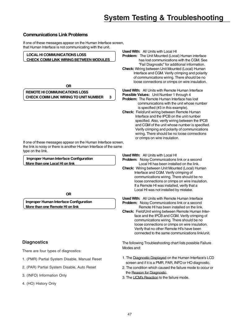
47
Communications Link Problems If one of these messages appear on the Human Interface screen,that Human Interface is not communicating with the unit.
Used With: All Units with Local HIProblem: The Unit Mounted (Local) Human interface has lost communications with the CGM. See "Fail Diagnostic" for additional information.Check: Wiring between Unit Mounted (Local) Human Interface and CGM. Verify crimping and polarity of communications wiring. There should be no loose connections or crimps on wire insulation.
ORUsed With: All Units with Remote Human InterfacePossible Values: Unit Number 1 through 4Problem: The Remote Human Interface has lost communications with the unit whose number is specified (#3 in this example).Check: Field/unit wiring between Remote Human Interface and the IPCB on the unit number specified. Also, verify wiring between the IPCB and CGM of the unit whose number is specified. Verify crimping and polarity of communications wiring. There should be no loose connections or crimps on wire insulation.
If one of these messages appear on the Human Interface screen,the link is noisy or there is another Human Interface of the sametype on the link.
Used With: All Units with Local HIProblem: Noisy Communications link or a second Local HI has been installed on the link.Check: Wiring between Unit Mounted (Local) Human Interface and CGM. Verify crimping of communications wiring. There should be no loose connections or crimps on wire insulation. If a Remote HI was installed, verify that a Local HI was not installed by mistake.
ORUsed With: All Units with Remote Human InterfaceProblem: Noisy Communications link or a second Remote HI has been installed on the link.Check: Field/Unit wiring between Remote Human Inter- face and the IPCB and CGM. Verify crimping of communications wiring. There should be no loose connections or crimps on wire insulation. Verify that no other Remote HI’s have been connected to the same communications link/unit.
The following Troubleshooting chart lists possible FailureModes and:
1. The Diagnostic Displayed on the Human Interface’s LCD screen and if it is a PMR, PAR, INFO or HO diagnostic.2. The condition which caused the failure mode to occur or the Reason for Diagnostic.3. The UCM’s Reaction to the failure mode.
LOCAL HI COMMUNICATIONS LOSSCHECK COMM LINK WIRING BETWEEN MODULES
REMOTE HI COMMUNICATIONS LOSS CHECK COMM LINK WIRING TO UNIT NUMBER 3
Improper Human Interface ConfigurationMore than one Local HI on link
Improper Human Interface Configuration More than one Remote HI on link
System Testing & Troubleshooting
Diagnostics
There are four types of diagnostics:
1. (PMR) Partial System Disable, Manual Reset
2. (PAR) Partial System Disable, Auto Reset
3. (INFO) Information Only
4. (HO) History Only

48
System Testing & TroubleshootingD
IAG
NO
ST
IC D
ISP
LA
YE
DR
EA
SO
N F
OR
DIA
GN
OS
TIC
UC
M’S
RE
AC
TIO
NR
ES
ET
RE
QU
IRE
DC
GM
ICS
Tem
pera
ture
Sen
sor
Fai
l
Pro
blem
: CG
M is
rec
eivi
ng a
sig
nal
whi
ch is
out
of r
ange
from
the
CG
M
ICS
Tem
pera
ture
Sen
sor
inpu
t.
The
uni
t is
read
ing
a si
gnal
that
is o
ut o
f ra
nge
for
the
CG
M IC
S T
empe
ratu
re
sens
or in
put o
n th
e C
GM
. (T
emp
< -
40 F
or
Tem
p >
200
F).
No
chan
ge in
uni
t ope
ratio
n oc
curs
. T
his
diag
nost
ic is
for
info
rmat
ion
only
.
(IN
FO
) A
n au
tom
atic
res
et o
ccur
s af
ter
the
CG
M IC
S T
empe
ratu
re
Sen
sor
retu
rns
to it
s al
low
able
ra
nge.
In o
rder
to p
reve
nt r
apid
cy
clin
g of
the
diag
nost
ic, t
here
is a
10
sec
ond
dela
y pr
ior
to th
e i
CG
M M
odul
e D
ata
Sto
rage
Err
or
Pro
blem
: The
re w
as a
dat
a tr
ansm
issi
on e
rror
.
Che
ck:
Thi
s ca
n be
cau
sed
by a
n in
term
itten
t pow
er lo
ss.
Tur
n th
e un
it of
f for
1-2
min
utes
, the
n ba
ck o
n ag
ain.
If d
iagn
ostic
per
sist
s, th
en
the
CG
M m
ay n
eed
to b
e re
plac
ed.
An
erro
r oc
curr
ed w
hile
the
CG
M w
as
writ
ing
data
to it
s in
tern
al n
on-v
olat
ile
mem
ory
(EE
PR
OM
).
An
info
rmat
ion
only
dia
gnos
tic w
ill
be d
ispl
ayed
at t
he H
uman
In
terf
ace.
(IN
FO
) A
man
ual r
eset
may
be
mad
e at
the
Hum
an In
terf
ace,
at
Tra
cer,
or
by c
yclin
g po
wer
to th
e C
GM
.
CG
M O
A T
emp
Sen
sor
Fai
lure
Pro
blem
: The
Out
side
Air
Tem
pera
ture
sen
sor
inpu
t is
out o
f ra
nge.
Che
ck: S
enso
r re
sist
ance
bet
wee
n 83
0 oh
ms
(200
F)
and
345.
7Koh
ms
(-
40 F
). I
f so,
che
ck fi
eld/
unit
wiri
ng
betw
een
Sen
sor
and
CG
M.
The
uni
t is
read
ing
a si
gnal
that
is o
ut o
f ra
nge
for
the
Out
side
Air
Tem
pera
ture
se
nsor
inpu
t on
the
CG
M. (
Tem
p <
-40
F
or T
emp
> 2
00 F
).
Uni
t act
ions
that
occ
ur w
hen
this
di
agno
stic
is a
ctiv
e in
clud
e;a.
Low
Am
bien
t Com
pres
sor
Lock
out f
unct
ion
is d
isab
led
b. L
ow A
mbi
ent P
ump
Ove
rrid
e fu
nctio
n is
act
ivat
ed (
ie: S
olut
ion
Pum
p O
N r
eque
st is
issu
ed).
c.
LP
C B
ypas
s T
ime
is s
et to
M
inim
um B
ypas
s T
ime
(tim
e us
ed
for
OA
Tem
p >
65 d
egF
).d.
If L
eavi
ng S
olut
ion
Res
et ty
pe
sele
cted
is O
A T
emp
Res
et, t
hen
th
e R
eset
type
rev
erts
to N
ON
E
for
the
dura
tion
of th
e fa
ilure
.
(PA
R)
An
auto
mat
ic r
eset
occ
urs
afte
r th
e O
A T
emp
inpu
t ret
urns
to
its a
llow
able
ran
ge. I
n or
der
to
prev
ent r
apid
cyc
ling
of th
e D
iagn
ostic
, the
re is
a 1
0 se
cond
de
lay
befo
re th
e au
tom
atic
res
et.
CG
M Z
one
Tem
p S
enso
r F
ailu
re
Pro
blem
: The
CG
M Z
one
Tem
pera
ture
sen
sor
inpu
t is
out o
f ra
nge.
Che
ck: S
enso
r re
sist
ance
bet
wee
n 83
0 oh
ms
(200
F)
and
345.
7Koh
ms
(-
40 F
). I
f so,
che
ck fi
eld/
unit
wiri
ng
betw
een
Sen
sor
and
CG
M.
The
Lea
ving
Sol
utio
n R
eset
type
se
lect
ed is
Zon
e T
emp
Res
et, a
nd th
e un
it is
rea
ding
a s
igna
l tha
t is
out o
f ra
nge
for
this
inpu
t (T
emp
< -
40 F
or
Tem
p >
200
F).
The
Res
et ty
pe r
ever
ts to
NO
NE
fo
r th
e du
ratio
n of
the
failu
re.
(PA
R)
An
auto
mat
ic r
eset
occ
urs
afte
r th
e de
sign
ated
Zon
e T
empe
ratu
re s
igna
l ret
urns
to it
s al
low
able
ran
ge. I
n or
der
to p
reve
nt
rapi
d cy
clin
g of
the
Dia
gnos
tic,
ther
e is
a 1
0 se
cond
del
ay b
efor
e th
e au
tom
atic
res
et.

49
System Testing & TroubleshootingD
IAG
NO
ST
IC D
ISP
LA
YE
DR
EA
SO
N F
OR
DIA
GN
OS
TIC
UC
M’S
RE
AC
TIO
NR
ES
ET
RE
QU
IRE
DC
ircui
t 1 P
umpd
own
Ter
min
ated
by
Tim
e
Pro
blem
: Uni
t wen
t thr
ough
P
umpd
own
on C
ircui
t 1 a
nd L
PC
ne
ver
trip
ped.
Pum
pdow
n w
as
term
inat
ed a
fter
30 s
econ
ds.
Che
ck: C
heck
circ
uit 1
pum
pdow
n so
leno
id v
alve
and
low
pre
ssur
e sw
itch
to v
erify
pro
per
oper
atio
n.
Uni
t rem
aine
d in
pum
pdow
n fo
r 30
se
cond
s w
ithou
t the
occ
urre
nce
of
an L
PC
eve
nt. P
umpd
own
sequ
ence
w
as te
rmin
ated
by
a 30
sec
ond
timer
.
No
Cha
nge
in u
nit o
pera
tion
occu
rs.
Thi
s di
agno
stic
is fo
r in
form
atio
n on
ly.
(IN
FO
) T
his
diag
nost
ic is
res
et w
hen
a co
mpr
esso
r on
Circ
uit 1
is s
tage
d on
due
to a
coo
ling
dem
and.
Crc
uit 2
Pum
pdow
n T
erm
inat
ed b
y T
ime
(Circ
uit #
2 40
-60
Ton
uni
ts o
nly)
Pro
blem
: Uni
t wen
t thr
ough
P
umpd
own
on C
ircui
t 2 a
nd L
PC
ne
ver
trip
ped.
Pum
pdow
n w
as
term
inat
ed a
fter
30 s
econ
ds.
Che
ck: C
heck
circ
uit 2
pum
pdow
n so
leno
id v
alve
and
low
pre
ssur
e sw
itch
to v
erify
pro
per
oper
atio
n.
Uni
t rem
aine
d in
pum
pdow
n fo
r 30
se
cond
s w
ithou
t the
occ
urre
nce
of
an L
PC
eve
nt. P
umpd
own
sequ
ence
w
as te
rmin
ated
by
a 30
sec
ond
timer
.
No
Cha
nge
in u
nit o
pera
tion
occu
rs.
Thi
s di
agno
stic
is fo
r in
form
atio
n on
ly.
(IN
FO
) T
his
diag
nost
ic is
res
et w
hen
a co
mpr
esso
r on
Circ
uit 2
is s
tage
d on
due
to a
coo
ling
dem
and.
Com
pres
sor
Con
tact
or F
ail -
Circ
uit 1
Pro
blem
: The
Com
pres
sor
Con
tact
or fo
r C
ircui
t #1
has
mal
func
tione
d.
The
circ
uit #
1 co
mpr
esso
r pr
ovin
g in
put o
n th
e S
CM
/MC
M is
det
ecte
d cl
osed
con
tinuo
usly
for
mor
e th
an 3
se
cond
s w
hile
nei
ther
com
pres
sor
outp
ut o
n C
ircui
t #1
is c
lose
d.
A "
Lock
out C
ircui
t #1"
req
uest
is
issu
ed to
the
Com
pres
sor
Sta
ging
C
ontr
ol fu
nctio
n. T
he C
ompr
esso
r R
elay
s, L
PC
Byp
ass
Rel
ay,
Liqu
id L
ine
Sol
enoi
d R
elay
, and
H
ot G
as B
ypas
s R
elay
for
C
ircui
t 1 a
re a
ll de
-ene
rgiz
ed
(PM
R)
A m
anua
l res
et is
req
uire
d af
ter
the
diag
nost
ic is
set
. It c
an b
e re
set b
y th
e H
I or
Tra
cer,
or
by
cycl
ing
pow
er to
the
CG
M.
Com
pres
sor
Con
tact
or F
ail -
Circ
uit 2
(Circ
uit #
2 40
-60
Ton
uni
ts o
nly)
Pro
blem
: The
Com
pres
sor
Con
tact
or fo
r C
ircui
t #2
has
mal
func
tione
d.
The
Circ
uit #
2 co
mpr
esso
r pr
ovin
g in
put o
n th
e M
CM
is d
etec
ted
clos
ed
cont
inuo
usly
for
mor
e th
an 3
se
cond
s w
hile
nei
ther
com
pres
sor
outp
ut o
n C
ircui
t #2
is c
lose
d.
A "
Lock
out C
ircui
t #2"
req
uest
is
issu
ed to
the
Com
pres
sor
Sta
ging
C
ontr
ol fu
nctio
n. T
he
Com
pres
sor
Rel
ays,
LP
C
Byp
ass
Rel
ay, a
nd L
iqui
d Li
ne
Sol
enoi
d R
elay
for
Circ
uit 2
are
al
l de-
ener
gize
d
PM
R)
A m
anua
l res
et is
req
uire
d af
ter
the
diag
nost
ic is
set
. It c
an b
e re
set b
y th
e H
I or
Tra
cer,
or
by
cycl
ing
pow
er to
the
CG
M.
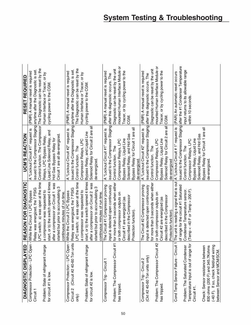
50
System Testing & TroubleshootingD
IAG
NO
ST
IC D
ISP
LA
YE
DR
EA
SO
N F
OR
DIA
GN
OS
TIC
UC
M’S
RE
AC
TIO
NR
ES
ET
RE
QU
IRE
DC
ompr
esso
r P
rote
ctio
n -
LPC
Ope
n -
Circ
uit 1
Pro
blem
: Sta
te o
f ref
riger
ant c
harg
e fo
r ci
rcui
t #1
is lo
w.
Whi
le th
e C
ircui
t 1 L
PC
Byp
ass
Rel
ay w
as e
nerg
ized
, the
7 P
SIG
LP
C s
witc
h: a
) w
as o
pen
at th
e tim
e a
com
pres
sor
was
req
uest
ed to
st
art,
or b
) th
e sw
itch
open
ed 4
tim
es
afte
r a
com
pres
sor
on C
ircui
t 1 w
as
star
ted
but p
rior
to a
ccum
ulat
ing
3 co
ntin
uous
min
utes
of r
un ti
me.
A “
Lock
out C
ircui
t #1”
req
uest
is
issu
ed to
the
Com
pres
sor
Sta
ging
C
ontr
ol fu
nctio
n. T
he C
ompr
esso
r R
elay
s, L
PC
Byp
ass
Rel
ay,
Liqu
id L
ine
Sol
enoi
d R
elay
, and
H
ot G
as B
ypas
s R
elay
for
C
ircui
t 1 a
re a
ll de
-ene
rgiz
ed.
(PM
R)
A m
anua
l res
et is
req
uire
d an
ytim
e af
ter
the
Dia
gnos
tic is
set
. T
he D
iagn
ostic
can
be
rese
t by
the
Hum
an In
terf
ace
or T
race
r, o
r by
cy
clin
g po
wer
to th
e C
GM
.
Com
pres
sor
Pro
tect
ion
- LP
C O
pen
-C
ircui
t 2
(Circ
uit #
2 40
-60
Ton
uni
ts
only
)
Pro
blem
: Sta
te o
f ref
riger
ant c
harg
e fo
r ci
rcui
t #2
is lo
w.
Whi
le th
e C
ircui
t 2 L
PC
Byp
ass
Rel
ay w
as e
nerg
ized
, the
7 P
SIG
LP
C s
witc
h: a
) w
as o
pen
at th
e tim
e a
com
pres
sor
was
req
uest
ed to
st
art,
or b
) th
e sw
itch
open
ed 4
tim
es
afte
r a
com
pres
sor
on C
ircui
t 2 w
as
star
ted
but p
rior
to a
ccum
ulat
ing
3 co
ntin
uous
min
utes
of r
un ti
me.
A “
Lock
out C
ircui
t #2”
req
uest
is
issu
ed to
the
Com
pres
sor
Sta
ging
C
ontr
ol fu
nctio
n. T
he
Com
pres
sor
Rel
ays,
LP
C
Byp
ass
Rel
ay, a
nd L
iqui
d Li
ne
Sol
enoi
d R
elay
for
Circ
uit 2
are
all
de-e
nerg
ized
.
(PM
R)
A m
anua
l res
et is
req
uire
d an
ytim
e af
ter
the
Dia
gnos
tic is
set
. T
he D
iagn
ostic
can
be
rese
t by
the
Hum
an In
terf
ace
or T
race
r, o
r by
cy
clin
g po
wer
to th
e C
GM
.
Com
pres
sor
Trip
- C
ircui
t 1
Pro
blem
: The
Com
pres
sor
Circ
uit #
1 ha
s tr
ippe
d.
The
Circ
uit #
1 C
ompr
esso
r pr
ovin
g in
put i
s de
tect
ed o
pen
cont
inuo
usly
fo
r m
ore
than
3 s
econ
ds w
hen
eith
er
or b
oth
com
pres
sor
outp
uts
on
Circ
uit #
1 ar
e en
ergi
zed
(as
desc
ribed
in th
e C
ompr
esso
r P
rote
ctio
n fu
nctio
n).
A “
Lock
out C
ircui
t #1”
req
uest
is
issu
ed to
the
Com
pres
sor
Sta
ging
C
ontr
ol fu
nctio
n. T
he
Com
pres
sor
Rel
ays,
LP
C
Byp
ass
Rel
ay, L
iqui
d Li
ne
Sol
enoi
d R
elay
, and
Hot
Gas
B
ypas
s R
elay
for
Circ
uit 1
are
all
de-e
ner g
ized
.
(PM
R)
A m
anua
l res
et is
req
uire
d af
ter
this
dia
gnos
tic o
ccur
s. T
he
Dia
gnos
tic c
an b
e re
set b
y th
e un
it m
ount
ed H
uman
Inte
rfac
e M
odul
e or
T
race
r, o
r by
cyc
ling
pow
er to
the
CG
M.
Com
pres
sor
Trip
- C
ircui
t 2(C
kt #
2 40
-60
Ton
uni
ts o
nly)
Pro
blem
: The
Com
pres
sor
Circ
uit #
2 ha
s tr
ippe
d.
The
Circ
uit #
2 C
ompr
esso
r pr
ovin
g in
put i
s de
tect
ed o
pen
cont
inuo
usly
fo
r m
ore
than
3 s
econ
ds w
hen
eith
er
or b
oth
com
pres
sor
outp
uts
on
Circ
uit #
2 ar
e en
ergi
zed
(as
desc
ribed
in th
e C
ompr
esso
r P
rote
ctio
n fu
nctio
n).
A “
Lock
out C
ircui
t #2”
req
uest
is
issu
ed to
the
Com
pres
sor
Sta
ging
C
ontr
ol fu
nctio
n. T
he
Com
pres
sor
Rel
ays,
LP
C
Byp
ass
Rel
ay, L
iqui
d Li
ne
Sol
enoi
d R
elay
for
Circ
uit 2
are
all
de-e
nerg
ized
(PM
R)
A m
anua
l res
et is
req
uire
d af
ter
this
dia
gnos
tic o
ccur
s. T
he
Dia
gnos
tic c
an b
e re
set b
y th
e un
it m
ount
ed H
uman
Inte
rfac
e M
odul
e or
T
race
r, o
r by
cyc
ling
pow
er to
the
CG
M.
Con
d T
emp
Sen
sor
Fai
lure
- C
ircui
t 1
Pro
blem
: The
Sat
urat
ed C
onde
nser
T
empe
ratu
re In
put i
s ou
t of r
ange
for
Circ
uit #
1.
Che
ck: S
enso
r re
sist
ance
bet
wee
n 83
0 oh
ms
(200
F)
and
345.
7Koh
ms
(-
40 F
). I
f so,
che
ck fi
eld/
unit
wiri
ng
betw
een
Sen
sor
and
MC
M/S
CM
.
The
uni
t is
read
ing
a si
gnal
that
is o
ut
of r
ange
for
the
circ
uit #
1 S
atur
ated
C
onde
nser
Tem
pera
ture
sen
sor.
(T
emp
< -
40 F
or
Tem
p >
200
F).
A “
Lock
out C
ircui
t # 1
” re
ques
t is
issu
ed to
the
Com
pres
sor
Sta
ging
C
ontr
ol fu
nctio
n. T
he
Com
pres
sor
Rel
ays,
LP
C
Byp
ass
Rel
ay, L
iqui
d Li
ne
Sol
enoi
d R
elay
, and
Hot
Gas
B
ypas
s R
elay
for
Circ
uit 1
are
all
de-e
nerg
ized
.
(PA
R)
An
auto
mat
ic r
eset
occ
urs
afte
r th
e #1
Con
dens
er T
empe
ratu
re
inpu
t ret
urns
to it
s al
low
able
ran
ge
with
in 1
0 se
cond
s.

51
System Testing & TroubleshootingD
IAG
NO
STIC
DIS
PLA
YED
REA
SON
FO
R D
IAG
NO
STIC
UC
M’S
REA
CTI
ON
RES
ET R
EQU
IRED
Con
d Te
mp
Sens
or F
ailu
re -
Circ
uit 2
(Circ
uit #
2 40
-60
Ton
units
onl
y)
Prob
lem
: The
Sat
urat
ed C
onde
nser
Te
mpe
ratu
re In
put i
s ou
t of r
ange
for
Circ
uit #
2.
Che
ck: S
enso
r res
ista
nce
betw
een
830
ohm
s (2
00 F
) and
345
.7Ko
hms
(-4
0 F)
. If
so,
The
unit
is re
adin
g a
sign
al th
at is
out
of
rang
e fo
r the
circ
uit #
2 Sa
tura
ted
Con
dens
er T
empe
ratu
re s
enso
r. (T
emp
< -4
0 F
or T
emp
> 20
0 F)
.
A “L
ocko
ut C
ircui
t #2”
requ
est i
s is
sued
to th
e C
ompr
esso
r Sta
ging
C
ontro
l fun
ctio
n. T
he C
ompr
esso
r R
elay
s, L
PC B
ypas
s R
elay
, and
Li
quid
Lin
e So
leno
id R
elay
for
Circ
uit 2
are
all
de-e
nerg
ized
.
(PAR
) An
auto
mat
ic re
set o
ccur
s af
ter
the
#2 C
onde
nser
Tem
p in
put r
etur
ns
to it
s al
low
able
rang
e w
ithin
10
seco
nds.
Cur
rent
Sen
sing
Mod
ule
Com
m F
ail
Prob
lem
: The
CG
M h
as lo
st
com
mun
icat
ions
with
the
Cur
rent
Se
nsin
g M
odul
e (C
SM)..
Che
ck: C
heck
fiel
d/un
it w
iring
bet
wee
n C
GM
and
CSM
.
The
CG
M h
as lo
st c
omm
unic
atio
ns
with
the
CSM
.N
o C
hang
e in
uni
t ope
ratio
n oc
curs
. Th
e C
urre
nt S
ensi
ng
Mod
ule
is u
sed
for m
onito
ring
purp
oses
onl
y, a
nd d
oes
not a
ffect
un
it op
erat
ion.
Thi
s di
agno
stic
is
for i
nfor
mat
ion
only
.
(PAR
) An
auto
mat
ic re
set o
ccur
s af
ter
com
mun
icat
ion
has
been
rest
ored
.
Emer
genc
y St
op
Prob
lem
: The
Em
erge
ncy
Stop
inpu
t on
the
CG
M is
ope
n.
An o
pen
circ
uit h
as o
ccur
red
on th
e Em
erge
ncy
Stop
inpu
t cau
sed
eith
er
by a
Hig
h D
uct T
emp
T-st
at tr
ip, o
r the
op
enin
g of
fiel
d-pr
ovid
ed c
onta
cts,
sw
itch,
etc
...
“OFF
or “
Clo
se” r
eque
sts
are
issu
ed a
s ap
prop
riate
to th
e fo
llow
ing
func
tions
;a.
Com
pres
sor S
tagi
ng c
ontro
l. (A
ll C
ompr
esso
r Rel
ays,
Liq
uid
Line
So
leno
id R
elay
s, L
PC B
ypas
s R
elay
, and
HG
BP R
elay
are
de
ener
gize
d).
b. E
vapo
rato
r Sol
utio
n Pu
mp
Con
trol.
(S
(PM
R) A
man
ual r
eset
is re
quire
d af
ter
the
Emer
genc
y St
op in
put r
eclo
ses.
Th
e D
iagn
ostic
can
be
rese
t by
the
Hum
an In
terfa
ce o
r Tra
cer o
r by
cycl
ing
pow
er to
the
CG
M.
EST/
LST
Low
Tem
pera
ture
Indi
catio
n
Prob
lem
: Eith
er th
e en
terin
g so
lutio
n te
mpe
ratu
re o
r the
leav
ing
solu
tion
tem
pera
ture
has
falle
n be
low
the
heat
ta
pe te
mpe
ratu
re s
etpo
int.
An a
bnor
mal
tem
pera
ture
read
ing
of
the
chill
ed s
olut
ion
exis
ts.
No
chan
ge in
the
unit
oper
atio
n.
This
dia
gnos
tic is
for i
nfor
mat
ion
only
.
(INFO
) An
auto
mat
ic re
set o
ccur
s af
ter
the
EST
and
LST
have
bot
h ris
en to
gr
eate
r tha
n 3o
F ab
ove
the
heat
tape
te
mpe
ratu
re s
etpo
int.
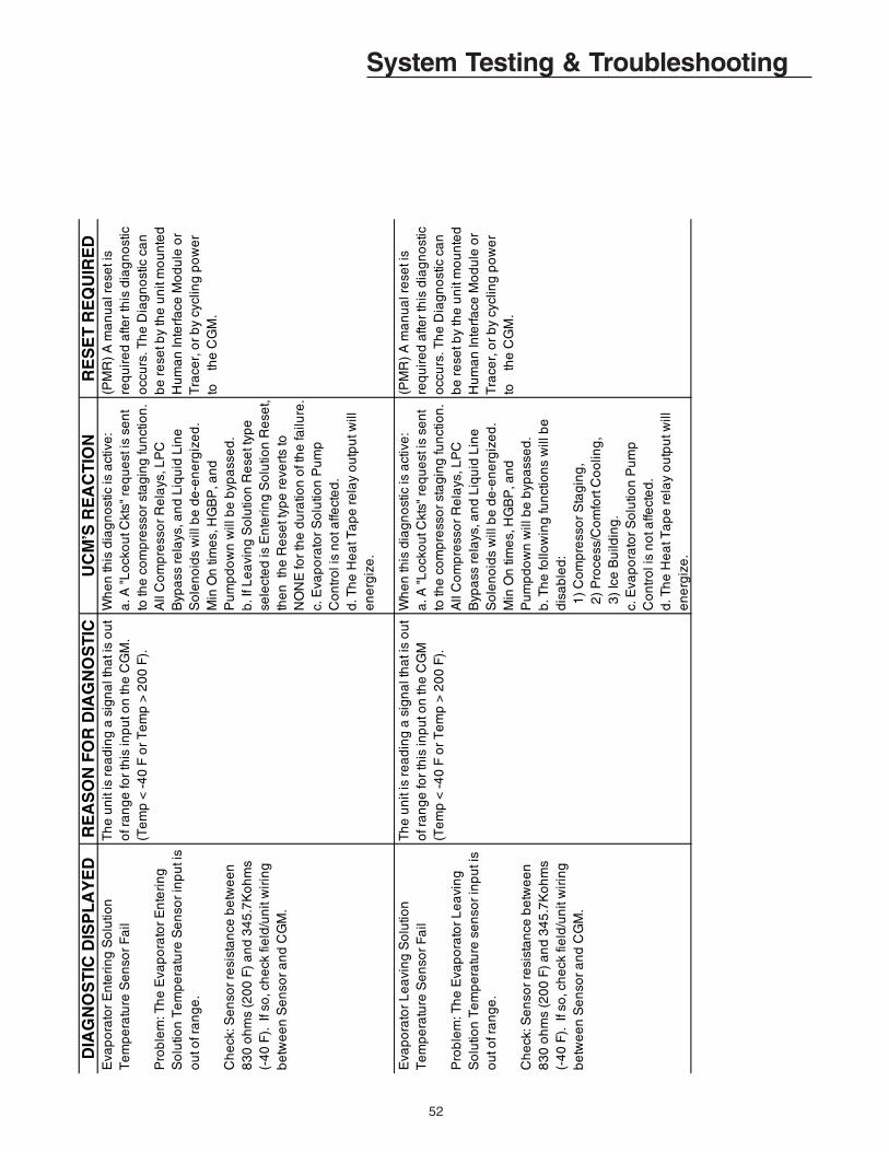
52
System Testing & TroubleshootingD
IAG
NO
ST
IC D
ISP
LA
YE
DR
EA
SO
N F
OR
DIA
GN
OS
TIC
UC
M’S
RE
AC
TIO
NR
ES
ET
RE
QU
IRE
DE
vap
ora
tor
En
teri
ng
So
lutio
n
Te
mp
era
ture
Se
nso
r F
ail
Pro
ble
m: T
he
Eva
po
rato
r E
nte
rin
g
So
lutio
n T
em
pe
ratu
re S
en
sor
inp
ut i
s o
ut o
f ra
ng
e.
Ch
eck
: Se
nso
r re
sist
an
ce b
etw
ee
n
83
0 o
hm
s (2
00
F)
an
d 3
45
.7K
oh
ms
(-4
0 F
). I
f so
, ch
eck
fie
ld/u
nit
wir
ing
b
etw
ee
n S
en
sor
an
d C
GM
.
Th
e u
nit
is r
ea
din
g a
sig
na
l th
at i
s o
ut
of r
an
ge
for
this
inp
ut o
n th
e C
GM
. (T
em
p <
-4
0 F
or
Te
mp
> 2
00
F).
Wh
en
this
dia
gn
ost
ic is
act
ive
:a
. A "
Lo
cko
ut C
kts"
re
qu
est
is s
en
t to
the
co
mp
ress
or
sta
gin
g fu
nct
ion
. A
ll C
om
pre
sso
r R
ela
ys, L
PC
B
ypa
ss r
ela
ys, a
nd
Liq
uid
Lin
e
So
len
oid
s w
ill b
e d
e-e
ne
rgiz
ed
. M
in O
n ti
me
s, H
GB
P, a
nd
P
um
pd
ow
n w
ill b
e b
ypa
sse
d.
b. I
f Le
avi
ng
So
lutio
n R
ese
t typ
e
sele
cte
d is
En
teri
ng
So
lutio
n R
ese
t, th
en
th
e R
ese
t typ
e r
eve
rts
to
NO
NE
for
the
du
ratio
n o
f th
e fa
ilure
.c.
Eva
po
rato
r S
olu
tion
Pu
mp
C
on
tro
l is
no
t affe
cte
d.
d. T
he
He
at T
ap
e r
ela
y o
utp
ut w
ill
en
erg
ize
.
(PM
R)
A m
an
ua
l re
set i
s
req
uir
ed
afte
r th
is d
iag
no
stic
o
ccu
rs. T
he
Dia
gn
ost
ic c
an
be
re
set b
y th
e u
nit
mo
un
ted
H
um
an
Inte
rfa
ce M
od
ule
or
Tra
cer,
or
by
cycl
ing
po
we
r to
th
e C
GM
.
Eva
po
rato
r L
ea
vin
g S
olu
tion
T
em
pe
ratu
re S
en
sor
Fa
il
Pro
ble
m: T
he
Eva
po
rato
r L
ea
vin
g
So
lutio
n T
em
pe
ratu
re s
en
sor
inp
ut i
s o
ut o
f ra
ng
e.
Ch
eck
: Se
nso
r re
sist
an
ce b
etw
ee
n
83
0 o
hm
s (2
00
F)
an
d 3
45
.7K
oh
ms
(-4
0 F
). I
f so
, ch
eck
fie
ld/u
nit
wir
ing
b
etw
ee
n S
en
sor
an
d C
GM
.
Th
e u
nit
is r
ea
din
g a
sig
na
l th
at i
s o
ut
of r
an
ge
for
this
inp
ut o
n th
e C
GM
(T
em
p <
-4
0 F
or
Te
mp
> 2
00
F).
Wh
en
this
dia
gn
ost
ic is
act
ive
:a
. A "
Lo
cko
ut C
kts"
re
qu
est
is s
en
t to
the
co
mp
ress
or
sta
gin
g fu
nct
ion
. A
ll C
om
pre
sso
r R
ela
ys, L
PC
B
ypa
ss r
ela
ys, a
nd
Liq
uid
Lin
e
So
len
oid
s w
ill b
e d
e-e
ne
rgiz
ed
. M
in O
n ti
me
s, H
GB
P, a
nd
P
um
pd
ow
n w
ill b
e b
ypa
sse
d.
b. T
he
follo
win
g fu
nct
ion
s w
ill b
e
dis
ab
led
: 1
) C
om
pre
sso
r S
tag
ing
, 2
) P
roce
ss/C
om
fort
Co
olin
g,
3)
Ice
Bu
ildin
g.
c. E
vap
ora
tor
So
lutio
n P
um
p
Co
ntr
ol i
s n
ot a
ffect
ed
.
d
. Th
e H
ea
t Ta
pe
re
lay
ou
tpu
t will
e
ne
rgiz
e.
(P
MR
) A
ma
nu
al r
ese
t is
req
uir
ed
afte
r th
is d
iag
no
stic
o
ccu
rs. T
he
Dia
gn
ost
ic c
an
be
re
set b
y th
e u
nit
mo
un
ted
H
um
an
Inte
rfa
ce M
od
ule
or
Tra
cer,
or
by
cycl
ing
po
we
r to
th
e C
GM
.
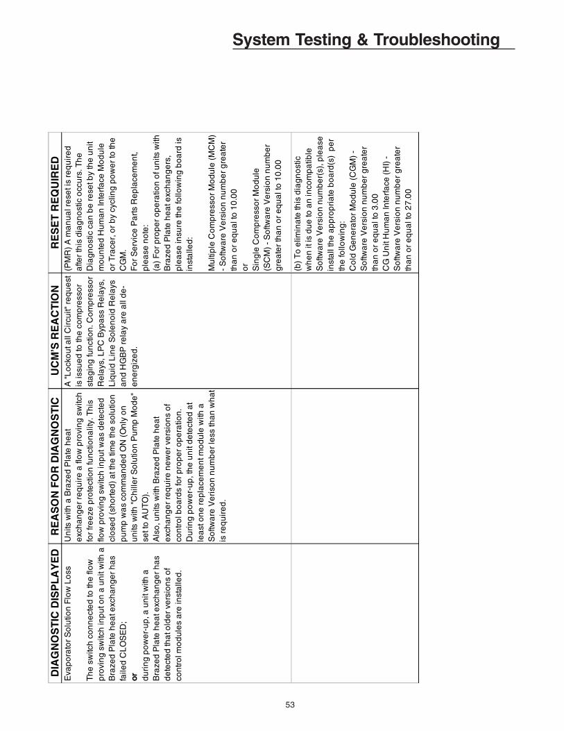
53
System Testing & TroubleshootingD
IAG
NO
ST
IC D
ISP
LA
YE
DR
EA
SO
N F
OR
DIA
GN
OS
TIC
UC
M’S
RE
AC
TIO
NR
ES
ET
RE
QU
IRE
DE
vap
ora
tor
So
lutio
n F
low
Lo
ss
Th
e s
witc
h c
on
ne
cte
d to
the
flo
w
pro
vin
g s
witc
h in
pu
t on
a u
nit
with
a
Bra
zed
Pla
te h
ea
t exc
ha
ng
er
ha
s fa
iled
CL
OS
ED
;
or
d
uri
ng
po
we
r-u
p, a
un
it w
ith a
B
raze
d P
late
he
at e
xch
an
ge
r h
as
de
tect
ed
tha
t old
er
vers
ion
s o
f co
ntr
ol m
od
ule
s a
re in
sta
lled
.
Un
its w
ith a
Bra
zed
Pla
te h
ea
t e
xch
an
ge
r re
qu
ire
a fl
ow
pro
vin
g s
witc
h
for
fre
eze
pro
tect
ion
fun
ctio
na
lity.
Th
is
flow
pro
vin
g s
witc
h in
pu
t wa
s d
ete
cte
d
clo
sed
(sh
ort
ed
) a
t th
e ti
me
the
so
lutio
n
pu
mp
wa
s co
mm
an
de
d O
N (
On
ly o
n
un
its w
ith "
Ch
ille
r S
olu
tion
Pu
mp
Mo
de
" se
t to
AU
TO
).
A
lso
, un
its w
ith B
raze
d P
late
he
at
exc
ha
ng
er
req
uir
e n
ew
er
vers
ion
s o
f co
ntr
ol b
oa
rds
for
pro
pe
r o
pe
ratio
n.
Du
rin
g p
ow
er-
up
, th
e u
nit
de
tect
ed
at
lea
st o
ne
re
pla
cem
en
t mo
du
le w
ith a
S
oftw
are
Ve
riso
n n
um
be
r le
ss th
an
wh
at
is r
eq
uir
ed
.
A "
Lo
cko
ut a
ll C
ircu
it" r
eq
ue
st
is is
sue
d to
the
co
mp
ress
or
sta
gin
g fu
nct
ion
. Co
mp
ress
or
Re
lays
, LP
C B
ypa
ss R
ela
ys,
Liq
uid
Lin
e S
ole
no
id R
ela
ys
an
d H
GB
P r
ela
y a
re a
ll d
e-
en
erg
ize
d.
(PM
R)
A m
an
ua
l re
set i
s re
qu
ire
d
afte
r th
is d
iag
no
stic
occ
urs
. Th
e
Dia
gn
ost
ic c
an
be
re
set b
y th
e u
nit
mo
un
ted
Hu
ma
n In
terf
ace
Mo
du
le
or
Tra
cer,
or
by
cycl
ing
po
we
r to
the
C
GM
.
Fo
r S
erv
ice
Pa
rts
Re
pla
cem
en
t, p
lea
se n
ote
:(a
) F
or
pro
pe
r o
pe
ratio
n o
f un
its w
ith
Bra
zed
Pla
te h
ea
t exc
ha
ng
ers
, p
lea
se in
sure
the
follo
win
g b
oa
rd is
in
sta
lled
:
Mu
ltip
le C
om
pre
sso
r M
od
ule
(M
CM
) -
So
ftwa
re V
ers
ion
nu
mb
er
gre
ate
r th
an
or
eq
ua
l to
10
.00
or
Sin
gle
Co
mp
ress
or
Mo
du
le(S
CM
) -
So
ftwa
re V
ers
ion
nu
mb
er
gre
ate
r th
an
or
eq
ua
l to
10
.00
(b)
To
elim
ina
te th
is d
iag
no
stic
w
he
n it
is d
ue
to a
n in
com
pa
tible
S
oftw
are
Ve
rsio
n n
um
be
r(s)
, ple
ase
in
sta
ll th
e a
pp
rop
ria
te b
oa
rd(s
) p
er
the
follo
win
g:
Co
ld G
en
era
tor
Mo
du
le (
CG
M)
- S
oftw
are
Ve
rsio
n n
um
be
r g
rea
ter
tha
n o
r e
qu
al t
o 3
.00
CG
Un
it H
um
an
Inte
rfa
ce (
HI)
-
So
ftwa
re V
ers
ion
nu
mb
er
gre
ate
r th
an
or
eq
ua
l to
27
.00

54
System Testing & TroubleshootingD
IAG
NO
ST
IC D
ISP
LA
YE
DR
EA
SO
N F
OR
DIA
GN
OS
TIC
UC
M’S
RE
AC
TIO
NR
ES
ET
RE
QU
IRE
DE
vap
So
lutio
n F
low
Pro
vin
g S
witc
h
Pro
ble
m: S
olu
tion
Flo
w S
witc
h is
op
en
afte
r th
e S
olu
tion
Pu
mp
is O
N.
Ch
eck
: Ve
rify
So
lutio
n P
um
po
pe
ratio
n a
nd
tha
t th
e E
vap
ora
tor
So
lutio
n F
low
Sw
itch
is w
ork
ing
pro
pe
rly.
Th
e d
iag
no
stic
ca
n o
ccu
r a
t an
y tim
ea
fter
the
Eva
po
rato
r S
olu
tion
Pu
mp
Re
lay
ha
s b
ee
n r
eq
ue
ste
d O
N, a
nd
the
So
lutio
n F
low
Sw
itch
inp
ut i
s d
ete
cte
dO
PE
N (
no
flo
w)
for
5 c
on
tinu
ou
sm
inu
tes.
Wh
en
the
So
lutio
n F
low
Sw
itch
inp
ut i
s d
ete
cte
d O
PE
N(n
o fl
ow
) fo
r 6
co
ntin
uo
us
seco
nd
s, th
e U
nit
will
de
-e
ne
rgiz
eth
e fo
llow
ing
re
lays
:C
om
pre
sso
r R
ela
ys, L
PC
Byp
ass
Re
lays
, Liq
uid
Lin
eS
ole
no
ids,
an
d H
GB
P R
ela
y.
(PA
R)
An
au
tom
atic
re
set
occ
urs
afte
r th
e E
vap
So
lutio
n F
low
Pro
vin
gS
witc
h h
as
de
tect
ed
So
lutio
n fl
ow
for
6co
ntin
uo
us
seco
nd
s.
Ext
ern
al L
ea
vin
g S
olu
tion
ST
P In
pu
t F
ail
Pro
ble
m: C
GM
is r
ece
ivin
g a
n
Ext
ern
al L
ea
vin
g S
olu
tion
Se
tpo
int
(LS
S)
Inp
ut s
ign
al w
hic
h is
ou
t of
ran
ge
. C
he
ck fi
eld
/un
it w
irin
g
be
twe
en
CG
M a
nd
Ext
ern
al
Le
avi
ng
So
lutio
n S
etp
oin
t p
ote
ntio
me
ter.
Th
e E
xte
rna
l Le
avi
ng
So
lutio
n S
etp
oin
t (L
SS
) is
de
sig
na
ted
as
the
Le
avi
ng
S
olu
tion
Se
tpo
int s
ou
rce
an
d it
is o
ut o
f ra
ng
e. O
ut o
f ra
ng
e is
de
fine
d a
s o
ne
of
the
follo
win
g:
a)
Ext
ern
al L
SS
> 6
5 d
eg
F o
r <
51
de
g
F fo
r u
nit
with
LS
S R
an
ge
51
-65
de
g F
.b
) E
xte
rna
l LS
S >
50
de
g F
or
< 4
0 d
eg
F
for
un
it w
ith L
SS
Ra
ng
e 4
0-5
0 d
eg
F.
c) E
xte
rna
l LS
S >
39
de
g F
or
< 3
0 d
eg
F
for
un
it w
ith L
SS
Ra
ng
e 3
0-3
9 d
eg
F.
d)
Ext
ern
al L
SS
> 2
9 d
eg
F o
r <
20
de
g
F fo
r u
nit
with
LS
S R
an
ge
20
-29
de
g F
.e
) E
xte
rna
l LS
S >
75
de
g F
or
< 1
0 d
eg
F
for
un
it w
ith L
SS
Ra
ng
e S
PE
CIA
L.
Wh
ile th
e d
iag
no
stic
is a
ctiv
e,
the
Le
avi
ng
So
lutio
n S
etp
oin
t w
ill r
eve
rt to
usi
ng
the
de
fau
lt (H
I) L
ea
vin
g S
olu
tion
Se
tpo
int.
(PA
R)
An
au
tom
atic
re
set o
ccu
rs
afte
r th
e E
xte
rna
l Le
avi
ng
So
lutio
n
Se
tpo
int r
etu
rns
to it
s a
llow
ab
le
ran
ge
. In
ord
er
to p
reve
nt r
ap
id
cycl
ing
of t
he
Dia
gn
ost
ic, t
he
re is
a
10
se
con
d d
ela
y b
efo
re th
e
au
tom
atic
re
set.
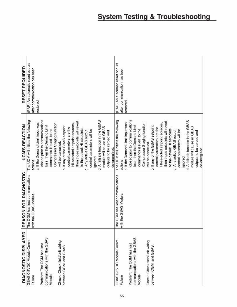
55
System Testing & TroubleshootingD
IAG
NO
ST
IC D
ISP
LA
YE
DR
EA
SO
N F
OR
DIA
GN
OS
TIC
UC
M’S
RE
AC
TIO
NR
ES
ET
RE
QU
IRE
DG
BA
S 0
-5V
DC
Mod
ule
Com
m
Fai
lure
Pro
blem
: The
CG
M h
as lo
st
com
mun
icat
ions
with
the
GB
AS
M
odul
e.
Che
ck: C
heck
fiel
d/un
it w
iring
be
twee
n C
GM
and
GB
AS
.
The
CG
M h
as lo
st c
omm
unic
atio
ns
with
the
GB
AS
Mod
ule.
The
UC
M w
ill in
itiat
e th
e fo
llow
ing
actio
ns;
a. If
the
Dem
and
Lim
it in
put w
as
clo
sed
prio
r to
com
mun
icat
ions
lo
ss, t
hen
the
Dem
and
Lim
it
com
man
ds is
sued
to
the
C
ompr
esso
r S
tagi
ng fu
nctio
n
will
be
canc
elle
d.b.
If a
ny o
f the
GB
AS
set
poin
t
con
trol
par
amet
ers
are
the
H
I-se
lect
ed s
etpo
int s
ourc
es,
th
en th
ose
setp
oint
s w
ill r
ever
t
to th
e de
faul
t HI s
etpo
ints
.c.
Any
act
ive
GB
AS
out
put
co
ntro
l par
amet
ers
will
be
ig
nore
d.d.
A fa
ilsaf
e fu
nctio
n in
the
GB
AS
m
odul
e w
ill c
ause
all
GB
AS
ou
tput
s to
be
zero
ed a
nd
de-e
ner g
ized
.
(PA
R)
An
auto
mat
ic r
eset
occ
urs
afte
r co
mm
unic
atio
n ha
s be
en
rest
ored
.
GB
AS
0-5
VD
C M
odul
e C
omm
F
ailu
re
Pro
blem
: The
CG
M h
as lo
st
com
mun
icat
ions
with
the
GB
AS
M
odul
e.
Che
ck: C
heck
fiel
d/un
it w
iring
be
twee
n C
GM
and
GB
AS
.
The
CG
M h
as lo
st c
omm
unic
atio
ns
with
the
GB
AS
Mod
ule.
The
UC
M w
ill in
itiat
e th
e fo
llow
ing
actio
ns;
a. If
the
Dem
and
Lim
it in
put w
as
clo
sed
prio
r to
com
mun
icat
ions
lo
ss, t
hen
the
Dem
and
Lim
it
com
man
ds is
sued
to
the
C
ompr
esso
r S
tagi
ng fu
nctio
n
will
be
canc
elle
d.b.
If a
ny o
f the
GB
AS
set
poin
t
con
trol
par
amet
ers
are
the
H
I-se
lect
ed s
etpo
int s
ourc
es,
th
en th
ose
setp
oint
s w
ill r
ever
t
to th
e de
faul
t HI s
etpo
ints
.c.
Any
act
ive
GB
AS
out
put
co
ntro
l par
amet
ers
will
be
ig
nore
d.d.
A fa
ilsaf
e fu
nctio
n in
the
GB
AS
m
odul
e w
ill c
ause
all
GB
AS
ou
tput
s to
be
zero
ed a
nd
de-e
nerg
ized
.
(PA
R)
An
auto
mat
ic r
eset
occ
urs
afte
r co
mm
unic
atio
n ha
s be
en
rest
ored
.

56
System Testing & TroubleshootingD
IAG
NO
ST
IC D
ISP
LA
YE
DR
EA
SO
N F
OR
DIA
GN
OS
TIC
UC
M’S
RE
AC
TIO
NR
ES
ET
RE
QU
IRE
DH
ot S
tart
Loa
d Li
mit
(Aut
o)
Pro
blem
: The
Lea
ving
Sol
utio
n T
empe
ratu
re is
too
hot.
Hot
Ope
ratio
n R
espo
nse
is s
et to
"50
%
CA
PA
CIT
Y P
ER
CK
T, A
UT
O R
ES
ET
D
IAG
". T
he L
eavi
ng S
olut
ion
Tem
p ex
ceed
ed th
e H
ot S
tart
Loa
d Li
mit
Set
poin
t afte
r th
e H
ot S
tart
Tim
e In
terv
al
expi
red.
Whi
le th
is d
iagn
ostic
is a
ctiv
e, th
e se
cond
com
pres
sor
on e
ach
refr
iger
ant c
ircui
t is
shut
off
and/
or p
reve
nted
from
sta
ging
O
N.
(PA
R)
An
auto
mat
ic r
eset
occ
urs
afte
r th
e Le
avin
g S
olut
ion
Tem
pera
ture
de
crea
ses
5 de
g F
or
mor
e be
low
the
Hot
Sta
rt L
oad
Lim
it S
etpo
int.
Hot
Sta
rt L
oad
Lim
it (I
nfo)
Pro
blem
: The
Lea
ving
Sol
utio
n T
empe
ratu
re is
too
hot.
Hot
Ope
ratio
n R
espo
nse
is s
et to
"A
LLO
W N
OR
MA
L O
PE
RA
TIO
N, I
NF
O
RE
SE
T D
IAG
". T
he L
eavi
ng S
olut
ion
Tem
p ex
ceed
ed th
e H
ot S
tart
Loa
d Li
mit
Set
poin
t afte
r th
e H
ot S
tart
Tim
e In
terv
al
expi
red.
No
chan
ge in
uni
t ope
ratio
n oc
curs
. T
his
diag
nost
ic is
for
info
rmat
ion
only
.
(IN
FO
) A
n au
tom
atic
res
et o
ccur
s af
ter
the
Leav
ing
Sol
utio
n T
empe
ratu
re
decr
ease
s 5
deg
F o
r m
ore
belo
w th
e H
ot S
tart
Loa
d Li
mit
Set
poin
t.
Hot
Sta
rt L
oad
Lim
it (M
an)
Pro
blem
: The
Lea
ving
Sol
utio
n T
empe
ratu
re is
too
hot.
Hot
Ope
ratio
n R
espo
nse
is s
et to
"S
HU
T O
FF
CO
MP
RE
SS
OR
S,
MA
NU
AL
RE
SE
T D
IAG
". T
he L
eavi
ng
Sol
utio
n T
emp
exce
eded
the
Hot
Sta
rt
Load
Lim
it S
etpo
int a
fter
the
Hot
Sta
rt
Tim
e In
terv
al e
xpire
d.
A "
lock
out a
ll C
kts"
req
uest
is
issu
ed to
the
com
pres
sor
stag
ing
func
tion.
The
Uni
t will
dee
nerg
ize
the
follo
win
g re
lays
: Com
pres
sor
Rel
ays,
LP
C B
ypas
s R
elay
s,
Liqu
id L
ine
Sol
enoi
ds, a
nd H
GB
P
Rel
ay.
Com
fort
/Pro
cess
Coo
ling,
an
d Ic
e B
uild
ing
are
term
inat
ed
and
prev
ente
d fr
om o
ccur
ring
until
the
diag
nost
ic c
ondi
tion
is
clea
red.
(PM
R)
A m
anua
l res
et is
req
uire
d af
ter
this
dia
gnos
tic o
ccur
s. T
he D
iagn
ostic
ca
n be
res
et b
y th
e un
it m
ount
ed
Hum
an In
terf
ace
Mod
ule
or T
race
r, o
r by
cyc
ling
pow
er to
the
CG
M.
Hot
Sta
rt L
oad
Lim
it S
etpo
int F
ail
Pro
blem
: The
Hot
Sta
rt L
oad
Lim
it S
etpo
int i
s ou
t of r
ange
.
Che
ck:
If H
ot S
tart
Loa
d Li
mit
Set
poin
t Sou
rce
is a
ssig
ned
to
eith
er G
BA
S m
odul
e, b
ut th
is
setp
oint
has
not
bee
n as
sign
ed to
on
e of
that
GB
AS
mod
ule’
s an
alog
inpu
ts, t
his
diag
nost
ic c
an
occu
r.
The
uni
t is
read
ing
a si
gnal
that
is o
ut o
f ra
nge
for
the
Hot
Sta
rt L
oad
Lim
it S
etpo
int.
The
def
ault
(HI)
Hot
Sta
rt L
oad
Lim
it S
etpo
int w
ill b
ecom
e th
e ac
tive
setp
oint
whi
le th
is
diag
nost
ic is
act
ive.
(PA
R)
An
auto
mat
ic r
eset
occ
urs
afte
r th
e de
sign
ated
Hot
Sta
rt L
oad
Lim
it S
etpo
int s
ourc
e se
nds
a si
gnal
that
is
with
in r
ange
for
10 c
ontin
uous
sec
onds
, or
afte
r a
diffe
rent
set
poin
t sou
rce
is
user
-def
ined
.

57
System Testing & TroubleshootingD
IAG
NO
ST
IC D
ISP
LA
YE
DR
EA
SO
N F
OR
DIA
GN
OS
TIC
UC
M’S
RE
AC
TIO
NR
ES
ET
RE
QU
IRE
DIB
TS
Adj
uste
d to
Mai
ntai
n M
in D
iff
Pro
blem
: The
act
ive
Ice
Bui
ld
Ter
min
ate
Set
poin
t (IB
TS
) is
cl
oser
to th
e Le
avin
g S
olut
ion
Cut
out T
emp
Set
poin
t tha
n th
e ca
lcul
ated
Min
imum
Diff
eren
tial.
The
act
ive
Ice
Bui
ld T
erm
inat
e S
etpo
int
and
the
Leav
ing
Sol
utio
n C
utou
t Tem
p S
etpo
int a
re to
o cl
ose
toge
ther
for
prop
er
unit
oper
atio
n.
The
act
ive
Ice
Bui
ld T
erm
inat
e S
etpo
int i
s se
t to
the
Leav
ing
Sol
utio
n C
utou
t Tem
p S
etpo
int
plus
the
larg
er o
f 1)
calc
ulat
ed
Min
imum
Diff
eren
tial v
alue
, or
2) 6
.5 d
eg F
.
(PA
R)
An
auto
mat
ic r
eset
occ
urs
afte
r th
e di
ffere
nce
betw
een
the
activ
e Ic
e B
uild
Ter
min
ate
Set
poin
t and
the
Leav
ing
Sol
utio
n C
utou
t Tem
p S
etpo
int
mee
ts th
e m
inim
um d
iffer
ence
re
quire
men
t.
Ice
Bui
ld T
erm
inat
e S
etpo
int F
ail
Pro
blem
: The
Ice
Bui
ld T
erm
inat
e S
etpo
int i
s ou
t of r
ange
.
Che
ck:
If Ic
e B
uild
Ter
min
ate
Set
poin
t Sou
rce
is a
ssig
ned
to
eith
er G
BA
S m
odul
e, b
ut th
is
setp
oint
has
not
bee
n as
sign
ed to
on
e of
that
GB
AS
mod
ule’
s an
alog
in
puts
, thi
s di
agno
stic
can
occ
ur.
The
uni
t is
read
ing
a si
gnal
that
is o
ut o
f ra
nge
for
the
Ice
Bui
ld T
erm
inat
e S
etpo
int.
The
def
ault
(HI)
Ice
Bui
ld
Ter
min
ate
Set
poin
t will
bec
ome
the
activ
e se
tpoi
nt w
hile
this
di
agno
stic
is a
ctiv
e.
(PA
R)
An
auto
mat
ic r
eset
occ
urs
afte
r th
e de
sign
ated
Ice
Bui
ld T
erm
inat
e S
etpo
int s
ourc
e se
nds
a si
gnal
that
is
with
in r
ange
for
10 c
ontin
uous
sec
onds
, or
afte
r a
diffe
rent
set
poin
t sou
rce
is
user
-def
ined
.
Leav
ing
Sol
utio
n S
etpo
int F
ail
Pro
blem
: The
des
igna
ted
Leav
ing
Sol
utio
n S
etpo
int i
s ou
t of r
ange
.
If ei
ther
GB
AS
mod
ule
is
desi
gnat
ed a
s th
e Le
avin
g S
olut
ion
Set
poin
t sou
rce,
ver
ify th
at G
BA
S
mod
ule
has
this
inpu
t ass
igne
d to
on
e of
it’s
ana
log
inpu
ts.
The
des
igna
ted
Leav
ing
Sol
utio
n S
etpo
int
sour
ce is
out
of r
ange
. O
ut o
f ran
ge is
de
fined
as
one
of th
e fo
llow
ing:
a) L
SS
> 6
5 de
g F
or
< 5
1 de
g F
for
unit
with
LS
S R
ange
51-
65 d
eg F
.b)
LS
S >
50
deg
F o
r <
40
deg
F fo
r un
it w
ith L
SS
Ran
ge 4
0-50
deg
F.
c) L
SS
> 3
9 de
g F
or
< 3
0 de
g F
for
unit
with
LS
S R
ange
30-
39 d
eg F
.d)
LS
S >
29
deg
F o
r <
20
deg
F fo
r un
it w
ith L
SS
Ran
ge 2
0-29
deg
F.
e) L
SS
> 7
5 de
g F
or
< 1
0 de
g F
for
unit
with
LS
S R
ange
SP
EC
IAL.
Whi
le th
e di
agno
stic
is a
ctiv
e,
the
Leav
ing
Sol
utio
n S
etpo
int
will
rev
ert t
o us
ing
the
defa
ult
(HI)
Lea
ving
Sol
utio
n S
etpo
int.
(PA
R)
An
auto
mat
ic r
eset
occ
urs
afte
r th
e de
sign
ated
Lea
ving
Sol
utio
n S
etpo
int r
etur
ns to
its
allo
wab
le r
ange
. In
ord
er to
pre
vent
rap
id c
yclin
g of
the
Dia
gnos
tic, t
here
is a
10
seco
nd d
elay
be
fore
the
auto
mat
ic r
eset
.
Liqu
id P
ress
ure
Sen
sor
Fai
l
Circ
uit 1
Pro
blem
: Circ
uit 1
Sat
urat
ed L
iqui
d Li
ne P
ress
ure
sens
or in
put i
s ou
t of
ran
ge.
Che
ck: C
heck
fiel
d/un
it w
iring
be
twee
n S
enso
r an
d S
SM
.
The
uni
t is
read
ing
a si
gnal
that
is o
ut o
f ra
nge
for
the
Circ
uit 1
Sat
urat
ed L
iqui
d Li
ne P
ress
ure
Sen
sor
inpu
t on
the
SS
M.
(Pre
ssur
e <
0 P
SIG
or
Pre
ssur
e >
400
P
SIG
).
The
Sup
erhe
at/S
ubco
ol
calc
ulat
ion
is in
valid
and
the
vaiu
es a
re s
et to
zer
o. N
o ot
her
chan
ge in
uni
t ope
ratio
n oc
curs
. T
his
diag
nost
ic is
for
info
rmat
ion
only
.
(IN
FO
) A
n au
tom
atic
res
et o
ccur
s af
ter
the
Circ
uit 1
Sat
urat
ed L
iqui
d P
ress
ure
Sen
sor
inpu
t ret
urns
to it
s al
low
able
ra
nge.
In
orde
r to
pre
vent
rap
id c
yclin
g of
the
Dia
gnos
tic, t
here
is a
10
seco
nd
dela
y be
fore
the
auto
mat
ic r
eset
.

58
System Testing & TroubleshootingD
IAG
NO
ST
IC D
ISP
LA
YE
DR
EA
SO
N F
OR
DIA
GN
OS
TIC
UC
M’S
RE
AC
TIO
NR
ES
ET
RE
QU
IRE
DL
iqu
id P
res
su
re S
en
so
r F
ail
Cir
cuit
2(C
ircu
it #
2 4
0-6
0 T
on
un
its o
nly
)
Pro
ble
m: C
ircu
it 2
Sa
tura
ted
Liq
uid
L
ine
Pre
ss
ure
se
ns
or
inp
ut i
s o
ut o
f ra
ng
e.
Ch
eck
: Ch
eck
fie
ld/u
nit
wir
ing
b
etw
ee
n S
en
so
r a
nd
SS
M.
Th
e u
nit
is r
ea
din
g a
sig
na
l th
at i
s o
ut
of r
an
ge
for
the
Cir
cuit
2 S
atu
rate
d
Liq
uid
Lin
e P
res
su
re S
en
so
r in
pu
t on
th
e S
SM
. (P
res
su
re <
0 P
SIG
or
Pre
ss
ure
> 4
00
PS
IG).
Th
e S
up
erh
ea
t/Su
bco
ol
calc
ula
tion
is in
valid
an
d th
e
vaiu
es
are
se
t to
ze
ro.
No
oth
er
cha
ng
e in
un
it o
pe
ratio
n o
ccu
rs.
Th
is d
iag
no
stic
is fo
r in
form
atio
n
on
ly.
(IN
FO
) A
n a
uto
ma
tic r
es
et o
ccu
rs
afte
r th
e C
ircu
it 2
Sa
tura
ted
Liq
uid
P
res
su
re S
en
so
r in
pu
t re
turn
s to
its
a
llow
ab
le r
an
ge
. In
ord
er
to p
reve
nt
rap
id c
yclin
g o
f th
e D
iag
no
stic
, th
ere
is
a 1
0 s
eco
nd
de
lay
be
fore
the
a
uto
ma
tic r
es
et.
Lo
w A
mb
ien
t Eva
po
rato
r S
olu
tion
P
um
p O
verr
ide
Pro
ble
m: O
uts
ide
Air
Te
mp
too
low
, re
qu
es
t So
lutio
n P
um
p to
ru
n to
ke
ep
So
lutio
n m
ovi
ng
.
Th
e O
uts
ide
Air
(A
mb
ien
t)
tem
pe
ratu
re is
be
low
the
Lo
w
Am
bie
nt E
vap
Pu
mp
Ove
rrid
e T
em
p
Se
tpo
int.
Th
e E
vap
ora
tor
So
lutio
n P
um
p
Re
lay
is e
ne
rgiz
ed
wh
ile th
is
con
diti
on
exi
sts
.
(PA
R)
An
au
tom
atic
re
se
t occ
urs
a
fter
the
Ou
tsid
e A
ir T
em
p
incr
ea
se
s 5
de
g F
or
mo
re a
bo
ve
the
Lo
w A
mb
ien
t Eva
po
rato
r P
um
p
Ove
rrid
e T
em
p S
etp
oin
t.
Lo
w S
olu
tion
Cu
tou
t Te
mp
era
ture
(A
uto
)
Pro
ble
m: T
he
Eva
po
rato
r L
ea
vin
g o
r E
nte
rin
g S
olu
tion
Te
mp
era
ture
is to
o
low
.
Wh
ile n
o c
om
pre
ss
ors
we
re r
un
nin
g,
the
Eva
po
rato
r S
olu
tion
T
em
pe
ratu
re(s
) w
en
t be
low
the
Lo
w
So
lutio
n C
uto
ut T
em
p S
etp
oin
t.
Wh
ile th
is d
iag
no
stic
is a
ctiv
e,
Co
mp
res
so
rs a
re p
reve
nte
d
fro
m s
tag
ing
on
. T
he
Un
it w
ill
de
en
erg
ize
the
follo
win
g:
Co
mp
res
so
r R
ela
ys, L
PC
B
ypa
ss
Re
lays
, Liq
uid
Lin
e
So
len
oid
s, a
nd
HG
BP
Re
lay.
(PA
R)
An
au
tom
atic
re
se
t occ
urs
a
fter
the
Eva
po
rato
r S
olu
tion
T
em
pe
ratu
re(s
) ri
se
s 4
de
g F
or
mo
re a
bo
ve th
e L
ow
So
lutio
n C
uto
ut
Te
mp
era
ture
Se
tpo
int.
Lo
w S
olu
tion
Cu
tou
t Te
mp
era
ture
(M
an
)
Pro
ble
m: T
he
Eva
po
rato
r L
ea
vin
g o
r E
nte
rin
g S
olu
tion
Te
mp
era
ture
is to
o
low
.
Wh
ile c
om
pre
ss
ors
we
re r
un
nin
g, t
he
E
vap
ora
tor
So
lutio
n T
em
pe
ratu
re(s
) w
en
t be
low
the
Lo
w S
olu
tion
Cu
tou
t T
em
pe
ratu
re S
etp
oin
t.
A "
Lo
cko
ut a
ll C
ircu
its"
req
ue
st i
s
iss
ue
d to
the
Co
mp
res
so
r S
tag
ing
Fu
nct
ion
. C
om
pre
ss
ors
a
re p
reve
nte
d fr
om
sta
gin
g o
n
an
d th
e U
nit
will
de
-en
erg
ize
the
fo
llow
ing
re
lays
: Co
mp
res
so
r R
ela
ys, L
PC
Byp
as
s R
ela
ys,
Liq
uid
Lin
e S
ole
no
ids
, an
d
HG
BP
Re
lay.
(PM
R)
A m
an
ua
l re
se
t is
re
qu
ire
d
afte
r th
is d
iag
no
stic
occ
urs
. Th
e
Dia
gn
os
tic c
an
be
re
se
t by
the
un
it m
ou
nte
d H
um
an
Inte
rfa
ce M
od
ule
o
r T
race
r, o
r b
y cy
clin
g p
ow
er
to th
e
CG
M.
Lo
w P
res
su
re C
on
tro
l Op
en
-
Cir
cuit
1
Pro
ble
m: T
he
re
frig
era
nt i
n C
ircu
it 1
is
co
ld a
nd
ma
y ca
us
e th
e S
olu
tion
in
the
Ch
ille
r b
arr
el t
o b
eco
me
too
co
ld.
Als
o, t
he
re m
ay
be
a s
tate
of
cha
rge
iss
ue
with
Cir
cuit
1.
With
on
e o
r m
ore
co
mp
res
so
rs
run
nin
g, t
he
hig
he
r p
res
su
re o
f th
e
two
LP
C s
witc
he
s o
n C
ircu
it 1
ha
s
op
en
ed
6 ti
me
s w
ith th
e L
PC
Byp
as
s
rela
y d
e-e
ne
rgiz
ed
, or
it w
as
op
en
at
the
tim
e th
e L
PC
Byp
as
s R
ela
y d
e-
en
erg
ize
d.
On
a s
tan
da
rd u
nit
this
is
the
45
PS
IG L
PC
sw
itch
, bu
t ca
n b
e
20
PS
IG o
r lo
we
r o
n u
nits
with
a lo
we
r L
ea
vin
g S
olu
tion
Se
tpo
int r
an
ge
.
A “
Lo
cko
ut C
ircu
it #
1”
req
ue
st i
s
iss
ue
d to
the
Co
mp
res
so
r S
tag
ing
Co
ntr
ol f
un
ctio
n.
Th
e
Co
mp
res
so
r R
ela
ys, L
PC
B
ypa
ss
Re
lay,
Liq
uid
Lin
e
So
len
oid
Re
lay,
an
d H
ot G
as
B
ypa
ss
Re
lay
for
Cir
cuit
1 a
re a
ll d
e-e
ne
rgiz
ed
.
(PM
R)
A m
an
ua
l re
se
t is
re
qu
ire
d
an
ytim
e a
fter
the
Dia
gn
os
tic is
se
t. T
he
Dia
gn
os
tic c
an
be
re
se
t by
the
H
um
an
Inte
rfa
ce o
r T
race
r, o
r b
y cy
clin
g p
ow
er
to th
e C
GM
.
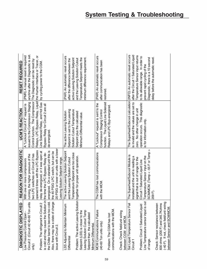
59
System Testing & TroubleshootingD
IAG
NO
ST
IC D
ISP
LA
YE
DR
EA
SO
N F
OR
DIA
GN
OS
TIC
UC
M’S
RE
AC
TIO
NR
ES
ET
RE
QU
IRE
DLo
w P
ress
ure
Con
trol
Ope
n -
C
ircui
t 2 (
Circ
uit #
2 40
-60
Ton
uni
ts
only
)
Pro
blem
: The
ref
riger
ant i
n C
ircui
t 2
is c
old
and
may
cau
se th
e S
olut
ion
in
the
Chi
ller
barr
el to
bec
ome
too
cold
. A
lso,
ther
e m
ay b
e a
stat
e of
cha
rge
issu
e w
ith C
ircui
t 2.
With
one
or
mor
e co
mpr
esso
rs
runn
ing,
the
high
er p
ress
ure
of th
e tw
o LP
C s
witc
hes
on C
ircui
t 2 h
as
open
ed 6
tim
es w
ith th
e LP
C B
ypas
s re
lay
de-e
nerg
ized
, or
it w
as o
pen
at
the
time
the
LPC
Byp
ass
Rel
ay d
e-en
ergi
zed.
On
a st
anda
rd u
nit t
his
is
the
45 P
SIG
LP
C s
witc
h, b
ut c
an b
e 20
PS
IG o
r lo
wer
on
units
with
a lo
wer
Le
avin
g S
olut
ion
Set
poin
t ran
ge.
A “
Lock
out C
ircui
t # 2
” re
ques
t is
issu
ed to
the
Com
pres
sor
Sta
ging
C
ontr
ol fu
nctio
n. T
he C
ompr
esso
r R
elay
s, L
PC
Byp
ass
Rel
ay, L
iqui
d Li
ne S
olen
oid
Rel
ay, a
nd H
ot G
as
Byp
ass
Rel
ay fo
r C
ircui
t 2 a
re a
ll de
-ene
rgiz
ed.
(PM
R)
A m
anua
l res
et is
req
uire
d an
ytim
e af
ter
the
Dia
gnos
tic is
set
. T
he D
iagn
ostic
can
be
rese
t by
the
Hum
an In
terf
ace
or T
race
r, o
r by
cyc
ling
pow
er to
the
CG
M.
LSS
Adj
uste
d to
Mai
ntai
n M
inim
um
Diff
eren
tial
Pro
blem
: The
act
ive
Leav
ing
Sol
utio
n S
etpo
int (
LSS
) is
clo
ser
to th
e Le
avin
g S
olut
ion
Cut
out T
emp
Set
poin
t tha
n th
e ca
lcul
ated
M
inim
um D
iffer
entia
l.
The
act
ive
Leav
ing
Sol
utio
n S
etpo
int
and
the
Leav
ing
Sol
utio
n C
utou
t T
empe
ratu
re S
etpo
int a
re to
o cl
ose
toge
ther
for
prop
er u
nit o
pera
tion.
The
act
ive
Leav
ing
Sol
utio
n S
etpo
int i
s se
t to
the
Leav
ing
Sol
utio
n C
utou
t Tem
pera
ture
S
etpo
int p
lus
the
calc
ulat
ed
Min
imum
Diff
eren
tial v
alue
.
(PA
R)
An
auto
mat
ic r
eset
occ
urs
afte
r th
e di
ffere
nce
betw
een
the
activ
e Le
avin
g S
olut
ion
Set
poin
t an
d th
e Le
avin
g S
olut
ion
Cut
out
Tem
pera
ture
Set
poin
t mee
ts th
e m
inim
um d
iffer
ence
req
uire
men
t.
MC
M C
omm
unic
atio
ns F
ailu
re(4
0-60
Ton
uni
ts o
nly)
Pro
blem
: The
CG
M h
as lo
st
com
mun
icat
ions
with
the
MC
M.
Che
ck: C
heck
fiel
d/un
it w
iring
be
twee
n C
GM
and
MC
M.
The
CG
M h
as lo
st c
omm
unic
atio
ns
with
the
MC
M.
A “
Lock
out”
req
uest
is s
ent t
o th
e C
ompr
esso
r S
tagi
ng C
ontr
ol
func
tion.
The
Liq
uid
Line
Sol
enoi
d R
elay
s an
d LP
C B
yp-e
nerg
ized
.
(PA
R)
An
auto
mat
ic r
eset
occ
urs
afte
r co
mm
unic
atio
n ha
s be
en
rest
ored
.
Sat
Liq
uid
Tem
pera
ture
Sen
sor
Fai
l C
ircui
t 1
Pro
blem
: Circ
uit 1
Sat
urat
ed L
iqui
d Li
ne T
empe
ratu
re s
enso
r in
put i
s ou
t of
ran
ge.
Che
ck: S
enso
r re
sist
ance
bet
wee
n 83
0 oh
ms
(200
F)
and
345.
7Koh
ms
(-
40 F
). I
f not
, che
ck fi
eld/
unit
wiri
ng
betw
een
Sen
sor
and
SC
M/M
CM
.
The
Sup
erhe
at/S
ubco
ol M
odul
e is
in
stal
led
and
the
unit
is r
eadi
ng a
si
gnal
that
is o
ut o
f ran
ge fo
r th
e C
ircui
t 1 S
atur
ated
Liq
uid
Line
T
empe
ratu
re S
enso
r in
put o
n th
e S
CM
/MC
M. (
Tem
p <
-55
F o
r T
emp
>
209
F).
The
Sup
erhe
at/S
ubco
ol c
alcu
latio
n is
inva
lid a
nd th
e va
lues
are
set
to
zero
. N
o ot
her
chan
ge in
uni
t op
erat
ion
occu
rs.
Thi
s di
agno
stic
is
for
info
rmat
ion
only
.
(IN
FO
) A
n au
tom
atic
res
et o
ccur
s af
ter
the
Circ
uit 1
Sat
urat
ed L
iqui
d T
empe
ratu
re S
enso
r in
put r
etur
ns
to it
s al
low
able
ran
ge.
In o
rder
to
prev
ent r
apid
cyc
ling
of th
e D
iagn
ostic
, the
re is
a 1
0 se
cond
de
lay
befo
re th
e au
tom
atic
res
et.

60
System Testing & TroubleshootingD
IAG
NO
ST
IC D
ISP
LA
YE
DR
EA
SO
N F
OR
DIA
GN
OS
TIC
UC
M’S
RE
AC
TIO
NR
ES
ET
RE
QU
IRE
DS
atur
ated
Liq
uid
Tem
pera
ture
S
enso
r F
ail -
Circ
uit 2
(Circ
uit #
2 40
-60
Ton
uni
ts o
nly)
Pro
blem
: Circ
uit 2
Sat
urat
ed L
iqui
d Li
ne T
empe
ratu
re s
enso
r in
put i
s ou
t of
ran
ge.
Che
ck: S
enso
r re
sist
ance
bet
wee
n 83
0 oh
ms
(200
F)
and
345.
7Koh
ms
(-
40 F
). I
f not
, che
ck fi
eld/
unit
wiri
ng
betw
een
Sen
sor
and
MC
M.
The
Sup
erhe
at/S
ubco
ol M
odul
e is
in
stal
led
and
the
unit
is r
eadi
ng a
si
gnal
that
is o
ut o
f ran
ge fo
r th
e C
ircui
t 2 S
atur
ated
Liq
uid
Line
T
empe
ratu
re S
enso
r in
put o
n th
e M
CM
. (T
emp
< -
40 F
or
Tem
p >
200
F
).
The
Sup
erhe
at/S
ubco
ol
calc
ulat
ion
is in
valid
and
the
valu
es a
re s
et to
zer
o. N
o ot
her
chan
ge in
uni
t ope
ratio
n oc
curs
. T
his
diag
nost
ic is
for
info
rmat
ion
only
.
(IN
FO
) A
n au
tom
atic
res
et o
ccur
s af
ter
the
Circ
uit 2
Sat
urat
ed L
iqui
d T
empe
ratu
re S
enso
r in
put r
etur
ns to
its
allo
wab
le r
ange
. In
ord
er to
pr
even
t rap
id c
yclin
g of
the
Dia
gnos
tic, t
here
is a
10
seco
nd
dela
y be
fore
the
auto
mat
ic r
eset
.
SC
M C
omm
unic
atio
ns F
ailu
re(2
0-30
Ton
uni
ts o
nly)
Pro
blem
: The
CG
M h
as lo
st
com
mun
icat
ions
with
the
SC
M.
Che
ck: C
heck
fiel
d/un
it w
iring
be
twee
n C
GM
and
SC
M.
The
CG
M h
as lo
st c
omm
unic
atio
ns
with
the
SC
M.
A “
Lock
out”
req
uest
is s
ent t
o th
e C
ompr
esso
r S
tagi
ng C
ontr
ol
func
tion.
The
Liq
uid
Line
S
olen
oid
Rel
ays
and
LPC
B
ypas
s R
elay
s ar
e de
-en
ergi
zed.
A fa
ilsaf
e fu
nctio
n in
th
e S
CM
will
cau
se a
ll S
CM
ou
tput
s to
be
zero
ed a
nd d
e-en
ergi
zed.
(PA
R)
An
auto
mat
ic r
eset
occ
urs
afte
r co
mm
unic
atio
n ha
s be
en
rest
ored
.
Suc
tion
Tem
p S
enso
r F
ail -
Circ
uit 1
Pro
blem
: Circ
uit 1
Suc
tion
Line
Tem
p se
nsor
inpu
t is
out o
f ran
ge.
Che
ck: S
enso
r re
sist
ance
bet
wee
n 83
0 oh
ms
(200
F)
and
345.
7Koh
ms
(-
40 F
). I
f not
, che
ck fi
eld/
unit
wiri
ng
betw
een
Sen
sor
and
SC
M/M
CM
.
The
Sup
erhe
at/S
ubco
ol M
odul
e is
in
stal
led
and
the
unit
is r
eadi
ng a
si
gnal
that
is o
ut o
f ran
ge fo
r th
e C
ircui
t 1 S
uctio
n Li
ne T
emp
Sen
sor
inpu
t on
the
SC
M/M
CM
. (T
emp
< -
40 F
or
Tem
p >
200
F).
The
Sup
erhe
at/S
ubco
ol
calc
ulat
ion
is in
valid
and
the
valu
es a
re s
et to
zer
o. N
o ot
her
chan
ge in
uni
t ope
ratio
n oc
curs
. T
his
diag
nost
ic is
for
info
rmat
ion
only
.
(IN
FO
) A
n au
tom
atic
res
et o
ccur
s af
ter
the
Circ
uit 1
Suc
tion
Line
Tem
p S
enso
r in
put r
etur
ns to
its
allo
wab
le
rang
e. I
n or
der
to p
reve
nt r
apid
cy
clin
g of
the
Dia
gnos
tic, t
here
is a
10
sec
ond
dela
y be
fore
the
auto
mat
ic r
eset
.
Suc
tion
Tem
p S
enso
r F
ail
- C
ircui
t 2(C
kt #
2 40
-60
Ton
uni
ts o
nly)
Pro
blem
: Circ
uit 2
Suc
tion
Line
Tem
p se
nsor
inpu
t is
out o
f ran
ge.
Che
ck: S
enso
r re
sist
ance
bet
wee
n 83
0 oh
ms
(200
F)
and
345.
7Koh
ms
(-
40 F
). I
f not
, che
ck fi
eld/
unit
wiri
ng
betw
een
Sen
sor
and
MC
M.
The
Sup
erhe
at/S
ubco
ol M
odul
e is
in
stal
led
and
the
unit
is r
eadi
ng a
si
gnal
that
is o
ut o
f ran
ge fo
r th
e C
ircui
t 2 S
uctio
n Li
ne T
empe
ratu
re
Sen
sor
inpu
t on
the
MC
M. (
Tem
p <
-40
F o
r T
emp
> 2
00 F
).
The
Sup
erhe
at/S
ubco
ol
calc
ulat
ion
is in
valid
and
the
valu
es a
re s
et to
zer
o. N
o ot
her
chan
ge in
uni
t ope
ratio
n oc
curs
. T
his
diag
nost
ic is
for
info
rmat
ion
only
.
(IN
FO
) A
n au
tom
atic
res
et o
ccur
s af
ter
the
Circ
uit 2
Suc
tion
Line
T
empe
ratu
re S
enso
r in
put r
etur
ns to
its
allo
wab
le r
ange
. In
ord
er to
pr
even
t rap
id c
yclin
g of
the
Dia
gnos
tic, t
here
is a
10
seco
nd
dela
y be
fore
the
auto
mat
ic r
eset
.
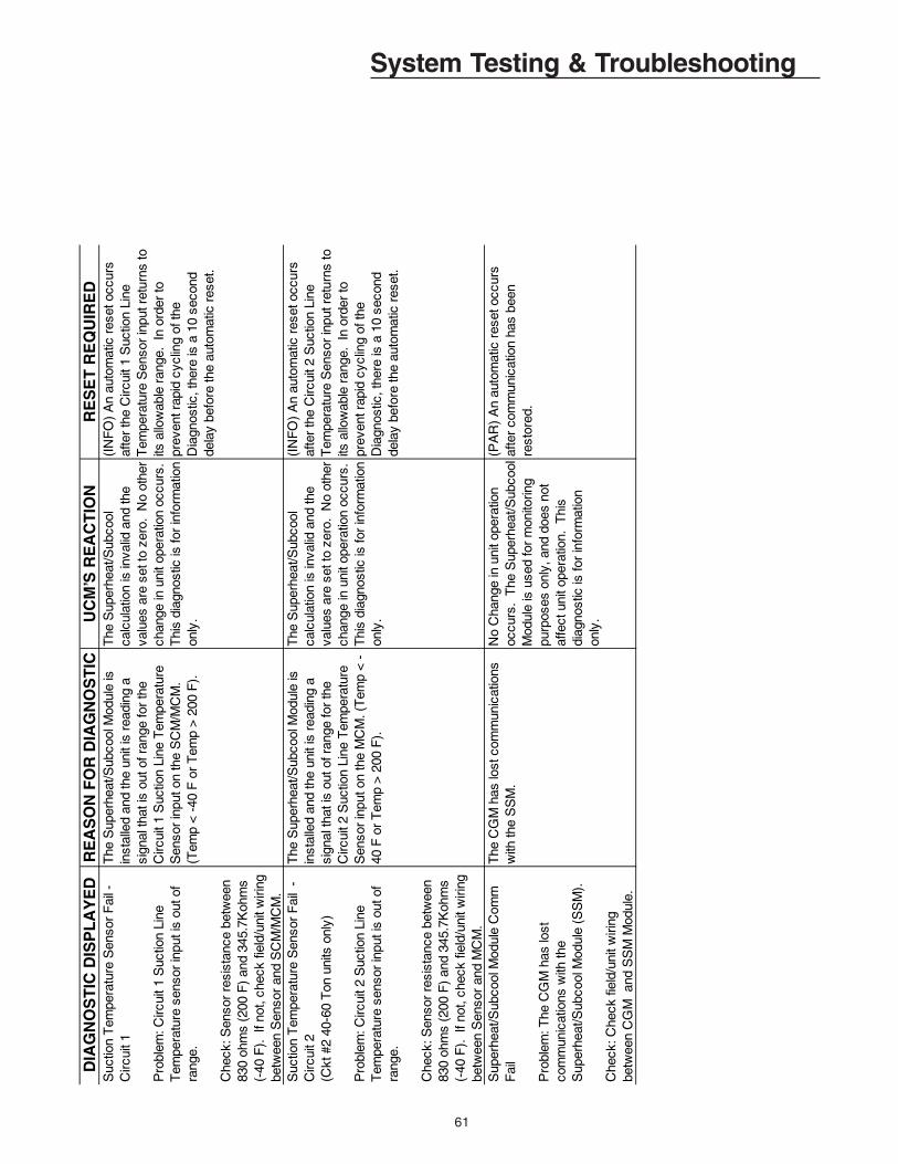
61
System Testing & TroubleshootingD
IAG
NO
ST
IC D
ISP
LA
YE
DR
EA
SO
N F
OR
DIA
GN
OS
TIC
UC
M’S
RE
AC
TIO
NR
ES
ET
RE
QU
IRE
DS
uctio
n T
empe
ratu
re S
enso
r F
ail -
C
ircui
t 1
Pro
blem
: Circ
uit 1
Suc
tion
Line
T
empe
ratu
re s
enso
r in
put i
s ou
t of
rang
e.
Che
ck: S
enso
r re
sist
ance
bet
wee
n 83
0 oh
ms
(200
F)
and
345.
7Koh
ms
(-
40 F
). I
f not
, che
ck fi
eld/
unit
wiri
ng
betw
een
Sen
sor
and
SC
M/M
CM
.
The
Sup
erhe
at/S
ubco
ol M
odul
e is
in
stal
led
and
the
unit
is r
eadi
ng a
si
gnal
that
is o
ut o
f ran
ge fo
r th
e C
ircui
t 1 S
uctio
n Li
ne T
empe
ratu
re
Sen
sor
inpu
t on
the
SC
M/M
CM
. (T
emp
< -
40 F
or
Tem
p >
200
F).
The
Sup
erhe
at/S
ubco
ol
calc
ulat
ion
is in
valid
and
the
valu
es a
re s
et to
zer
o. N
o ot
her
chan
ge in
uni
t ope
ratio
n oc
curs
. T
his
diag
nost
ic is
for
info
rmat
ion
only
.
(IN
FO
) A
n au
tom
atic
res
et o
ccur
s af
ter
the
Circ
uit 1
Suc
tion
Line
T
empe
ratu
re S
enso
r in
put r
etur
ns to
its
allo
wab
le r
ange
. In
ord
er to
pr
even
t rap
id c
yclin
g of
the
Dia
gnos
tic, t
here
is a
10
seco
nd
dela
y be
fore
the
auto
mat
ic r
eset
.
Suc
tion
Tem
pera
ture
Sen
sor
Fai
l -
Circ
uit 2
(Ckt
#2
40-6
0 T
on u
nits
onl
y)
Pro
blem
: Circ
uit 2
Suc
tion
Line
T
empe
ratu
re s
enso
r in
put i
s ou
t of
rang
e.
Che
ck: S
enso
r re
sist
ance
bet
wee
n 83
0 oh
ms
(200
F)
and
345.
7Koh
ms
(-
40 F
). I
f not
, che
ck fi
eld/
unit
wiri
ng
betw
een
Sen
sor
and
MC
M.
The
Sup
erhe
at/S
ubco
ol M
odul
e is
in
stal
led
and
the
unit
is r
eadi
ng a
si
gnal
that
is o
ut o
f ran
ge fo
r th
e C
ircui
t 2 S
uctio
n Li
ne T
empe
ratu
re
Sen
sor
inpu
t on
the
MC
M. (
Tem
p <
-40
F o
r T
emp
> 2
00 F
).
The
Sup
erhe
at/S
ubco
ol
calc
ulat
ion
is in
valid
and
the
valu
es a
re s
et to
zer
o. N
o ot
her
chan
ge in
uni
t ope
ratio
n oc
curs
. T
his
diag
nost
ic is
for
info
rmat
ion
only
.
(IN
FO
) A
n au
tom
atic
res
et o
ccur
s af
ter
the
Circ
uit 2
Suc
tion
Line
T
empe
ratu
re S
enso
r in
put r
etur
ns to
its
allo
wab
le r
ange
. In
ord
er to
pr
even
t rap
id c
yclin
g of
the
Dia
gnos
tic, t
here
is a
10
seco
nd
dela
y be
fore
the
auto
mat
ic r
eset
.
Sup
erhe
at/S
ubco
ol M
odul
e C
omm
F
ail
Pro
blem
: The
CG
M h
as lo
st
com
mun
icat
ions
with
the
Sup
erhe
at/S
ubco
ol M
odul
e (S
SM
).
Che
ck: C
heck
fiel
d/un
it w
iring
be
twee
n C
GM
and
SS
M M
odul
e.
The
CG
M h
as lo
st c
omm
unic
atio
ns
with
the
SS
M.
No
Cha
nge
in u
nit o
pera
tion
occu
rs.
The
Sup
erhe
at/S
ubco
ol
Mod
ule
is u
sed
for
mon
itorin
g pu
rpos
es o
nly,
and
doe
s no
t af
fect
uni
t ope
ratio
n. T
his
diag
nost
ic is
for
info
rmat
ion
only
.
(PA
R)
An
auto
mat
ic r
eset
occ
urs
afte
r co
mm
unic
atio
n ha
s be
en
rest
ored
.
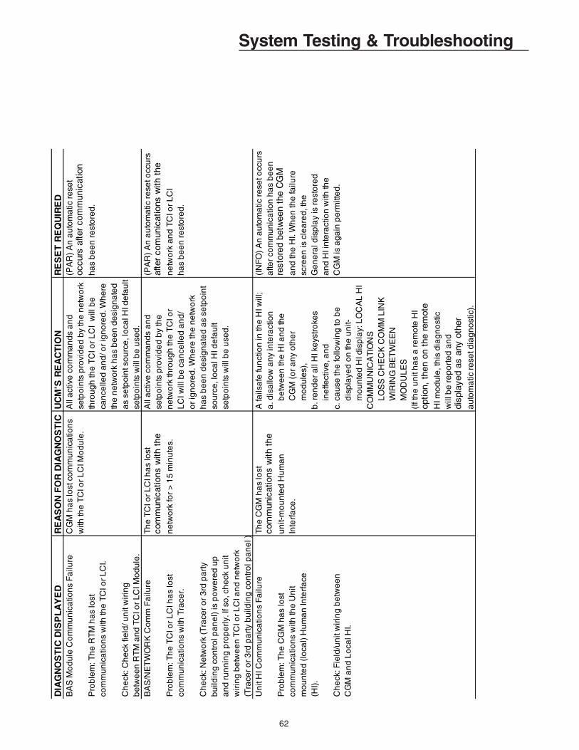
62
System Testing & TroubleshootingD
IAG
NO
ST
IC D
ISP
LA
YE
D
RE
AS
ON
FO
R D
IAG
NO
ST
IC
UC
M’S
RE
AC
TIO
N
RE
SE
T R
EQ
UIR
ED
B
AS
Mo
du
le C
om
mu
nic
atio
ns
Fa
ilure
CG
M h
as
lost
co
mm
un
ica
tion
sA
ll a
ctiv
e c
om
ma
nd
s a
nd
(PA
R)
An
au
tom
atic
re
set
with
the
TC
I or
LC
I Mo
du
le.
setp
oin
ts p
rovi
de
d b
y th
e n
etw
ork
occu
rs a
fter
com
mun
icat
ion
Pro
ble
m: T
he
RT
M h
as
lost
thro
ug
h th
e T
CI o
r L
CI
will
be
ha
s b
ee
n r
est
ore
d.
com
mu
nic
atio
ns
with
the
TC
I or
LC
I.ca
nce
lled
an
d/ o
r ig
no
red
. Wh
ere
th
e n
etw
ork
ha
s b
ee
n d
esi
gn
ate
d
Ch
eck
: Ch
eck
fie
ld/ u
nit
wir
ing
as
setp
oin
t so
urc
e, l
oca
l HI d
efa
ult
be
twe
en
RT
M a
nd
TC
I or
LC
I Mo
du
le.
setp
oin
ts w
ill b
e u
sed
.B
AS
/NE
TW
OR
K C
om
m F
ailu
reT
he
TC
I or
LC
I ha
s lo
st
All
act
ive
co
mm
an
ds
an
d(P
AR
) A
n a
uto
ma
tic r
ese
t occ
urs
com
mun
icat
ions
with
the
se
tpo
ints
pro
vid
ed
by
the
af
ter
com
unic
atio
ns w
ith t
he
Pro
ble
m: T
he
TC
I or
LC
I ha
s lo
stn
etw
ork
for
> 1
5 m
inu
tes.
ne
two
rk th
rou
gh
the
TC
I or
ne
two
rk a
nd
TC
I or
LC
I co
mm
un
ica
tion
s w
ith T
race
r.L
CI w
ill b
e c
an
celle
d a
nd
/h
as
be
en
re
sto
red
.o
r ig
no
red
. Wh
ere
the
ne
two
rk
Ch
eck
: Ne
two
rk (
Tra
cer
or
3rd
pa
rty
ha
s b
ee
n d
esi
gn
ate
d a
s se
tpo
int
bu
ildin
g c
on
tro
l pa
ne
l) is
po
we
red
up
so
urc
e, l
oca
l HI d
efa
ult
an
d r
un
nin
g p
rop
erl
y. If
so
, ch
eck
un
it se
tpo
ints
will
be
use
d.
wir
ing
be
twe
en
TC
I or
LC
I an
d n
etw
ork
(Tra
cer
or
3rd
pa
rty
bu
ildin
g c
on
tro
l pa
ne
l )
Un
it H
I Co
mm
un
ica
tion
s F
ailu
re
Th
e C
GM
ha
s lo
st
A fa
ilsa
fe fu
nct
ion
in th
e H
I will
; (I
NF
O)
An
au
tom
atic
re
set o
ccu
rs
com
mun
icat
ions
with
the
a. d
isa
llow
an
y in
tera
ctio
n
afte
r co
mm
un
ica
tion
ha
s b
ee
n
Pro
ble
m: T
he
CG
M h
as
lost
u
nit-
mo
un
ted
Hu
ma
n
b
etw
ee
n th
e H
I an
d th
ere
stor
ed b
etw
een
the
CG
Mco
mm
un
ica
tion
s w
ith th
e U
nit
Inte
rfa
ce.
C
GM
(o
r a
ny
oth
er
an
d th
e H
I. W
he
n th
e fa
ilure
m
ou
nte
d (
loca
l) H
um
an
Inte
rfa
ce
m
od
ule
s),
scre
en
is c
lea
red
, th
e
(HI)
. b
. re
nd
er
all
HI k
eys
tro
kes
Ge
ne
ral d
isp
lay
is r
est
ore
d
ine
ffect
ive
, an
d
an
d H
I in
tera
ctio
n w
ith th
e
Ch
eck
: Fie
ld/u
nit
wir
ing
be
twe
en
c.
ca
use
the
follo
win
g to
be
C
GM
is a
ga
in p
erm
itte
d.
CG
M a
nd
Lo
cal H
I.
dis
pla
yed
on
the
un
it-
m
ou
nte
d H
I dis
pla
y: L
OC
AL
HI
C
OM
MU
NIC
AT
ION
S
L
OS
S C
HE
CK
CO
MM
LIN
K
W
IRIN
G B
ET
WE
EN
M
OD
UL
ES
(If t
he
un
it h
as
a r
em
ote
HI
op
tion,
the
n on
the
rem
ote
H
I mo
du
le, t
his
dia
gn
ost
ic
will
be
re
po
rte
d a
nd
di
spla
yed
as a
ny o
ther
au
tom
atic
re
set d
iag
no
stic
).
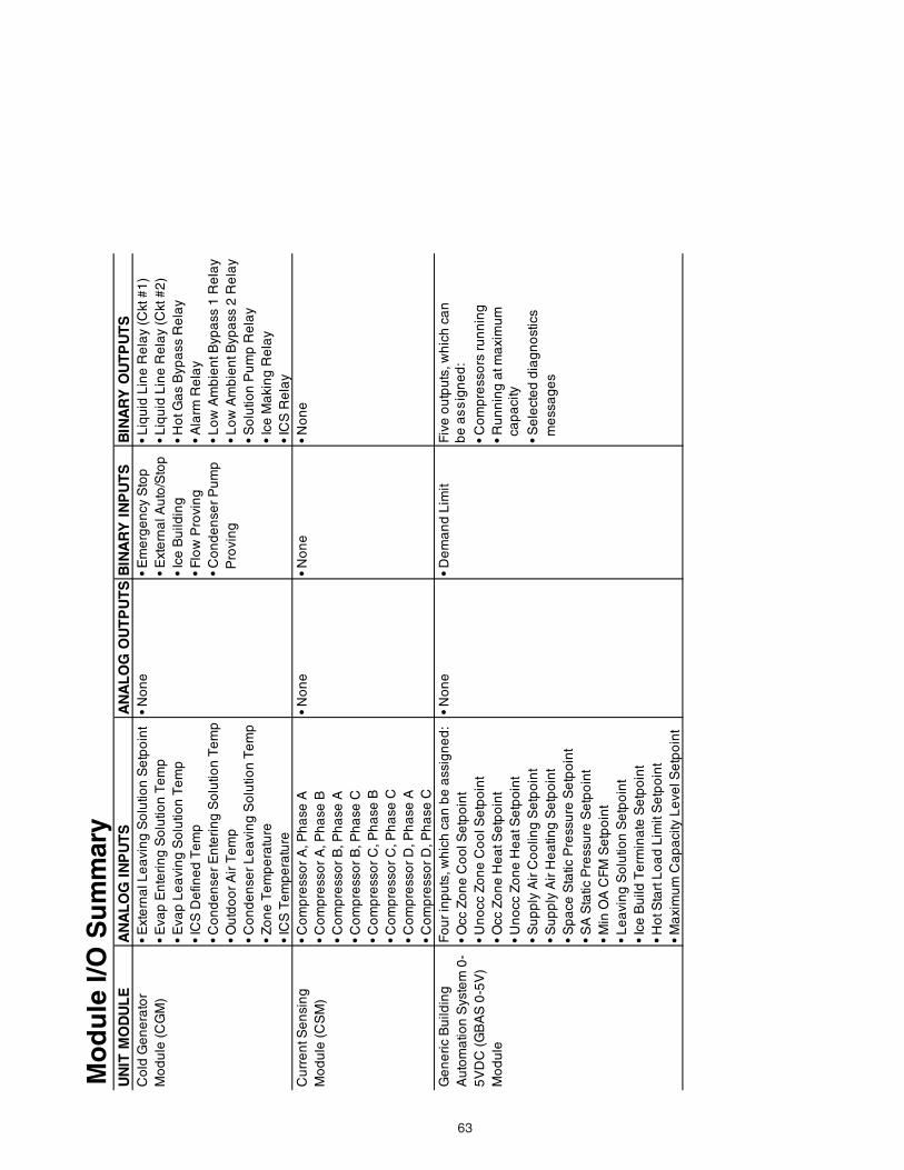
63
Mo
du
le I/
O S
um
mar
yU
NIT
MO
DU
LE
AN
AL
OG
IN
PU
TS
AN
AL
OG
OU
TP
UT
SB
INA
RY
IN
PU
TS
BIN
AR
Y O
UT
PU
TS
Co
ld G
en
era
tor
• E
xte
rna
l Le
avi
ng
So
lutio
n S
etp
oin
t•
No
ne
• E
me
rge
ncy
Sto
p•
Liq
uid
Lin
e R
ela
y (C
kt #
1)
Mo
du
le (
CG
M)
• E
vap
En
teri
ng
So
lutio
n T
em
p•
Ext
ern
al A
uto
/Sto
p•
Liq
uid
Lin
e R
ela
y (C
kt #
2)
• E
vap
Le
avi
ng
So
lutio
n T
em
p•
Ice
Bu
ildin
g•
Ho
t Ga
s B
ypa
ss R
ela
y•
ICS
De
fine
d T
em
p•
Flo
w P
rovi
ng
• A
larm
Re
lay
• C
on
de
nse
r E
nte
rin
g S
olu
tion
Te
mp
• C
on
de
nse
r P
um
p
• L
ow
Am
bie
nt B
ypa
ss 1
Re
lay
• O
utd
oo
r A
ir T
em
p P
rovi
ng
• L
ow
Am
bie
nt B
ypa
ss 2
Re
lay
• C
on
de
nse
r L
ea
vin
g S
olu
tion
Te
mp
• S
olu
tion
Pu
mp
Re
lay
• Z
on
e T
em
pe
ratu
re•
Ice
Ma
kin
g R
ela
y•
ICS
Te
mp
era
ture
• IC
S R
ela
yC
urr
en
t Se
nsi
ng
• C
om
pre
sso
r A
, Ph
ase
A•
No
ne
• N
on
e•
No
ne
Mo
du
le (
CS
M)
• C
om
pre
sso
r A
, Ph
ase
B•
Co
mp
ress
or
B, P
ha
se A
• C
om
pre
sso
r B
, Ph
ase
C•
Co
mp
ress
or
C, P
ha
se B
• C
om
pre
sso
r C
, Ph
ase
C•
Co
mp
ress
or
D, P
ha
se A
• C
om
pre
sso
r D
, Ph
ase
CG
en
eri
c B
uild
ing
Fo
ur
inp
uts
, wh
ich
ca
n b
e a
ssig
ne
d:
• N
on
e•
De
ma
nd
Lim
itF
ive
ou
tpu
ts, w
hic
h c
an
A
uto
ma
tion
Sys
tem
0-
• O
cc Z
on
e C
oo
l Se
tpo
int
be
as
sig
ne
d:
5V
DC
(G
BA
S 0
-5V
)•
Un
occ
Zo
ne
Co
ol S
etp
oin
t•
Co
mp
ress
ors
ru
nn
ing
Mo
du
le•
Occ
Zo
ne
He
at S
etp
oin
t•
Ru
nn
ing
at m
axi
mu
m
• U
no
cc Z
on
e H
ea
t Se
tpo
int
ca
pa
city
• S
up
ply
Air
Co
olin
g S
etp
oin
t•
Se
lect
ed
dia
gn
ost
ics
• S
up
ply
Air
He
atin
g S
etp
oin
t m
ess
ag
es
• S
pa
ce S
tatic
Pre
ssu
re S
etp
oin
t•
SA
Sta
tic P
ress
ure
Se
tpo
int
• M
in O
A C
FM
Se
tpo
int
• L
ea
vin
g S
olu
tion
Se
tpo
int
• Ic
e B
uild
Te
rmin
ate
Se
tpo
int
• H
ot S
tart
Lo
ad
Lim
it S
etp
oin
t•
Ma
xim
um
Ca
pa
city
Le
vel S
etp
oin
t
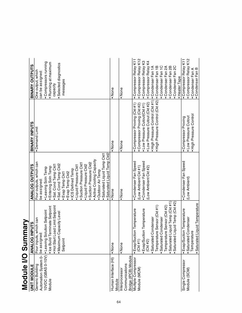
64
Mo
du
le I/
O S
um
mar
yU
NIT
MO
DU
LE
AN
AL
OG
IN
PU
TS
AN
AL
OG
OU
TP
UT
SB
INA
RY
IN
PU
TS
BIN
AR
Y O
UT
PU
TS
Ge
ne
ric
Bu
ildin
gF
ou
r in
pu
ts, w
hic
h c
an
F
ou
r o
utp
uts
, wh
ich
ca
n
• D
em
an
d L
imit
On
e o
utp
ut,
wh
ich
A
uto
ma
tion
Sys
tem
0-
be
as
sig
ne
d:
be
as
sig
ne
d:
can
be
as
sig
ne
d:
10
VD
C (
GB
AS
0-1
0V
)•
Le
avi
ng
So
lutio
n S
etp
oin
t•
Le
avi
ng
So
ln T
em
p•
Co
mp
ress
ors
ru
nn
ing
Mo
du
le•
Ice
Bu
ild T
erm
ina
te S
etp
oin
t•
En
teri
ng
So
ln T
em
p•
Ru
nn
ing
at m
axi
mu
m
• H
ot S
tart
Lo
ad
Lim
it S
etp
oin
t•
Sa
t. C
on
d T
em
p C
kt1
ca
pa
cit y
• M
axi
mu
m C
ap
aci
ty L
eve
l•
Sa
t. C
on
d T
em
p C
kt2
• S
ele
cte
d d
iag
no
stic
s S
etp
oin
t•
Eva
p T
em
p C
kt1
m
ess
ag
es
• E
vap
Te
mp
Ckt
2•
ICS
De
fine
d T
em
p•
Liq
uid
Pre
ssu
re C
kt1
• S
uct
ion
Pre
ssu
re C
kt1
• L
iqu
id P
ress
ure
Ckt
2•
Su
ctio
n P
ress
ure
Ckt
2•
Act
ive
Co
olin
g C
ap
aci
ty•
Ou
tdo
or
Air
Te
mp
• S
atu
rate
d L
iqu
id T
em
p C
kt1
• S
atu
rate
d L
iqu
id T
em
p C
kt2
Hu
ma
n In
terf
ace
(H
I)•
No
ne
•
No
ne
•
No
ne
•
No
ne
Mo
du
leIn
terp
roce
sso
r•
No
ne
•
No
ne
•
No
ne
•
No
ne
Co
mm
un
ica
tion
sB
rid
ge
(IP
CB
) M
od
ule
Mu
ltip
le C
om
pre
sso
r•
Eva
p/S
uct
ion
Te
mp
era
ture
• C
on
de
nse
r F
an
Sp
ee
d•
Co
mp
ress
or
Pro
vin
g (
Ckt
#1
)•
Co
mp
ress
or
Re
lay
K1
1M
od
ule
(M
CM
) (
Ckt
#1
)(L
ow
Am
bie
nt C
kt #
1)
• C
om
pre
sso
r P
rovi
ng
(C
kt #
2)
• C
om
pre
sso
r R
ela
y K
12
• E
vap
/Su
ctio
n T
em
pe
ratu
re•
Co
nd
en
ser
Fa
n S
pe
ed
• L
ow
Pre
ssu
re C
uto
ut(
Ckt
#1
)•
Co
mp
ress
or
Re
lay
K3
(C
kt #
2)
(Lo
w A
mb
ien
t Ckt
#2
)•
Lo
w P
ress
ure
Cu
tou
t (C
kt #
2)
• C
om
pre
sso
r R
ela
y K
4•
Sa
tura
ted
Co
nd
en
ser
• H
igh
Pre
ssu
re C
on
tro
l (C
kt #
1)
• C
on
de
nse
r F
an
1A
Te
mp
era
ture
Se
nso
r (C
kt #
1)
• H
igh
Pre
ssu
re C
on
tro
l (C
kt #
2)
• C
on
de
nse
r F
an
1B
• S
atu
rate
d C
on
de
nse
r •
Co
nd
en
ser
Fa
n 1
C T
em
pe
ratu
re S
en
sor
(Ckt
#2
)•
Co
nd
en
ser
Fa
n 2
A•
Sa
tura
ted
Liq
uid
Te
mp
(C
kt #
1)
• C
on
de
nse
r F
an
2B
• S
atu
rate
d L
iqu
id T
em
p (
Ckt
#2
)•
Co
nd
en
ser
Fa
n 2
C•
He
ate
r T
ap
eS
ing
le C
om
pre
sso
r•
Eva
p/S
uct
ion
Te
mp
era
ture
• C
on
de
nse
r F
an
Sp
ee
d•
Co
mp
ress
or
Pro
vin
g•
Co
mp
ress
or
Re
lay
K1
1M
od
ule
(S
CM
)•
Sa
tura
ted
Co
nd
en
ser
(Lo
w A
mb
ien
t)•
Lo
w P
ress
ure
Cu
tou
t•
Co
mp
ress
or
Re
lay
K1
2 T
em
pe
ratu
re•
Hig
h P
ress
ure
Co
ntr
ol
• C
on
de
nse
r F
an
A•
Sa
tura
ted
Liq
uid
Te
mp
era
ture
• C
on
de
ns
er
Fa
n B
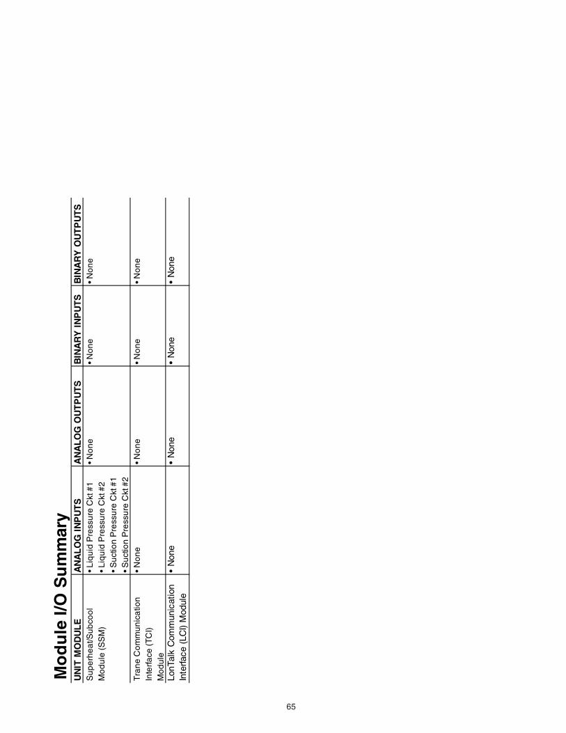
65
Mo
du
le I/
O S
um
mar
yU
NIT
MO
DU
LE
AN
AL
OG
IN
PU
TS
AN
AL
OG
OU
TP
UT
SB
INA
RY
IN
PU
TS
BIN
AR
Y O
UT
PU
TS
Su
pe
rhe
at/S
ub
coo
l•
Liq
uid
Pre
ssu
re C
kt #
1•
No
ne
• N
on
e•
No
ne
Mo
du
le (
SS
M)
• L
iqu
id P
ress
ure
Ckt
#2
• S
uct
ion
Pre
ssu
re C
kt #
1•
Su
ctio
n P
ress
ure
Ckt
#2
Tra
ne
Co
mm
un
ica
tion
• N
on
e•
No
ne
• N
on
e•
No
ne
Inte
rfa
ce (
TC
I)M
od
ule
LonT
alk
Com
mun
icat
ion
• N
one
• N
one
• N
one
• N
one
Inte
rface
(LC
I) M
odul
e

66
IndexH
Head Pressure Control ..........................................26HI module; See Human Interface ModuleHuman Interface Keypad ......................................... 8See Figure 2
Human Interface Module ......................................... 7See Figure 1
I
Ice Building ............................................................26Information Format ................................................23Interprocessor Communications Board ................... 6
Leaving Solution Setpoint ........................................ 5Leaving Solution Temperature Control Point ........... 5Literature Change History ........................................ 2Loop Stabilization ..................................................25Low Ambient Compressor Lock-out ......................... 5
L
LonTalk .............................................................. 4,5,6LonTalk Communication Interface
(LCI) module ........... 4,5,6,19,23,24,28,38,61,63
M
Manual disconnect switch 1S14 .............................. 6See Manual Disconnect Switch
Menu Keys ............................................................... 8microelectronic control system ................................ 6See UCM Control System
Model Number Description ...................................... 4Module I/O Summary .............................................62
N
NEXT Key ................................................................ 9No Configuration ...................................................... 7non-Trane building control systems; See Generic BAS
Module
Symbols
+ (Plus) Key...9+ (Plus) Key...10; See Data Manipulation Keys- (Minus) Key...9- (Minus) Key...10; See Data Manipulation Keys115V Control Circuit Switch (1S1)...7; See Power
Disconnecting Switches24V Transformer Switch (1S70)...7; See Power
Disconnecting Switches
A
Active Setpoint ......................................................... 5AUTO Key ................................................................ 9
C
CANCEL Key ........................................................... 8Cautions ................................................................... 4Cold Generator Module ........................................... 6Communications Link Problems ............................46Compressor Module ................................................ 6Compressor Protection Switch ................................ 5CONFIGURATION Key ............................................ 8CONFIGURATION Menu .......................................36Control Band ............................................................ 5Control circuit switch (1S1) ...................................... 6Control Parameters ................................................32Control Point ............................................................ 5Current Sensing Module .......................................... 6CUSTOM Key .......................................................... 9
D
Data Manipulation Keys ........................................... 8Deadband ................................................................ 5DIAGNOSTICS Key ................................................. 8Disconnect switch 1S14........................................... 6
E
Emergency Stop ...................................................... 5ENTER Key.............................................................. 8External Auto/Stop ................................................... 5
G
Generic Building Automation System ...................... 6

67
P
PREVIOUS Key ....................................................... 9
R
Remote Human Interface ........................................ 5See Interprocessor Communication Module
Reset Amount Maximum ......................................... 5Reset End Temperature ........................................... 5Reset Start Temperature .......................................... 5
S
SCM or MCM; See Compressor ModuleSERVICE MODE Key .............................................. 8SERVICE MODE Menu .........................................39Setpoint Source Selection .....................................34SETPOINTS Key ..................................................... 8SETUP Menu ........................................................23SETUP Key .............................................................. 8STATUS Key ............................................................ 8STATUS Menu .......................................................15STOP Key ................................................................ 9Superheat & Subcooling Module ............................. 6
T
TEST START Key (SERVICE) ...............................9Trane Communications Interface Module ..............6Trane integrated comfort systems; See Trane
Communications Interface ModuleTransformer switch 1S70 .......................................6
U
Unit Control Module ...............................................5Unit Nameplate ......................................................4Unit Operation Keys ...............................................9Unit Status (Unit Off or Stopped) ...........................7Unit Status (Unit On) ..............................................7
W
Warnings ................................................................4

68