programmable polyphonic synihe modulethe korg ex-8000 polyphonic synthe module. to obtain optimum...
TRANSCRIPT
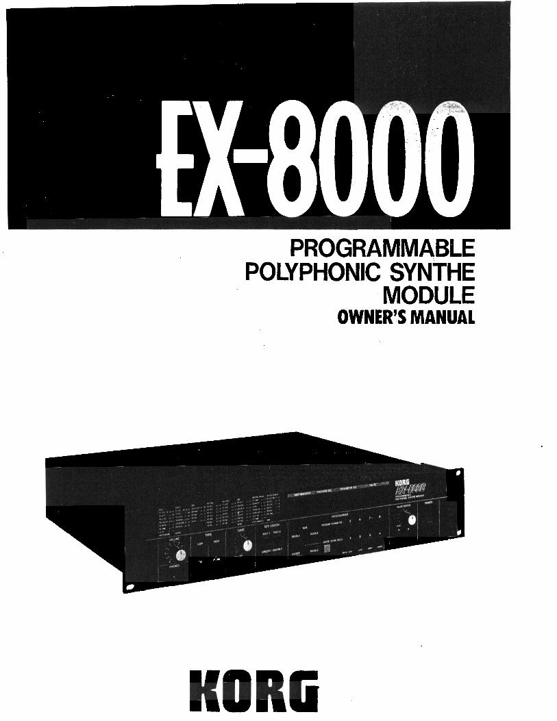
PROGRAMMABLEPOLYPHONIC SYNiHE
MODULEO W N E R ’ S M A N U A L
KORG
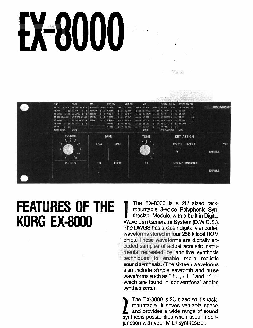
FEATURES OF THE 1 The EX-8000 is a 2U sized rack-mountable 8-voice Polyphonrc Syn-
KORG EX-8000thesizer Module, with a built-in Digital
Waveform Generator System (D.W.G.S.).The DWGS has sixteen digitally encodedwaveforms stored in four 256 kilobit ROMchips. These waveforms are digitally en-coded samples of actual acoustic instru-
. merits‘ recreated by additive synthesistechniques to enable more realisticsound synthesis: (The sixteen waveformsalso include simple sawtooth and pulsewaveforms such as “ I’Y , l-7 ” and “ TL ”which are found in conventional analogsynthesizers.)
The EX-8000 is 2U-sized so it’s rack-mountable. It saves valuable spaceand provides a wide range of sound
synthesis possibilities when used in con-junction with your MIDI synthesizer.

Thank you and congratulations on your choice ofthe KORG EX-8000 Polyphonic Synthe Module.To obtain optimum performance, please read thismanual carefully before using this synthesizer.
3 Uses two Digital Oscillators, analognoise generator, and VCF and VCAmodules for sound synthesis. You
can enjoy the uniqueness of digital soundplus quick and logical sound synthesis asin analog control.
4 The EX-8000 accepts Initial Touch(key velocity) and After Touch (chan-nel pressure) data, so real-time con-
trol of output volume, timbre and pitchmodulation is at your fingertips whenused with a synthesizer featuring thesefunctions.
5 A programmable digital delay is in-cluded to store clear stereo effects(Chorus, Doubling, Short Delay, and
Long Delay) for each of 64 tone colors inthe programmer.
6 Auto Bend is included for more real-istic synthesis of human voice andbrass sounds.
7 Key Assign mode provides two poly-phonic modes and two unisonmodes, which are effective for play-
ing solo or bass parts or using Portamen-to.
8
Built-in Portamento produces a grad-ual change in pitch from one note toanother.
9 The Key Window function limits thearea on the keyboard which one EX-8000 controls, from one point on the
keyboard to another.
IMPORTANT SAFETY PRECAUTIONS
I LOCATIONTo avoid malfunction do not use this unit in the following locations for longperiods of time:0 In direct sunlight.0 Exposed to extremes of temperature or humidity.0 In sandy or dusty places.
n POWER SUPPLY0 Use only with rated AC voltage. If you will be using this unit in a country
having a different voltage, be sure to obtain the proper transformer toconvert to rated voltage.l To help prevent noise and degraded sound quality, avoid using the
same outlet as other equipment or branching off extension cords sharedby other equipment.
llNPUT/OUTPUT JACKS AND CONNECTION CORDSBe sure to use standard “guitar” cables with phone plugs, such as thecable supplied with this instrument, for input and output connections to therear panel of the EX-8000. Never insert any other kind of plug into thesejacks.
n Preventing ELECTRICAL INTERFERENCEAs a microprocessor based device, the EX-8000 is extremely flexible inoperation, yet may possibly perform erratically if exposed to electrical in-terference from other electrical devices and fluorescent lamps. Avoid oper-ating the EX-8000 near possible sources of interference. If somethingseems to be wrong, try turning off the power, waiting about ten seconds,them turning it back on. This resets the computer circuits to their initialstate so performance should return to normal.
n HANDLE GENTLYKnobs and switches are designed to provide positive operation with a lighttouch. Excessive force may cause damage.
n MAINTENANCEWipe the exterior with a soft, dry cloth. Never use,paint thinner, benzeneor other solvents.
l KEEP THIS MANUALStore this manual in a safe place for future reference.
n MEMORY BACKUPl To protect your programmed memory contents, the EX-8000 utilizes a
built-in rechargeable backup battery power supply. Battery life is ratedat five years or more, so replacement is recommended after five years.Contact your Korg dealer or authorized service center at that time.
OFor maximum security, save your sound programs on tape, using thebuilt-in tape interface system. Then if memory contents are accidentallyerased or altered, you can simply load the data back into EX-8000 in-ternal memory in seconds!
-4
CONTENTS
FEATURES & FUNCTIONSIFRONTPANEL2 REAR PANEL/BASIC SETUP
SELECTING PROGRAMS1 PROGRAM NUMBERS2HOWTOSELECTAPROGRAMNUMBER
BASIC OPERATION1PARAMETERSANDVALUES2HOWTOEDlTVALUES3TUNlNG PROCEDURE
MIDI1 MIDI PARAMETERS2KEYWlNDOW3TRANSMITTED/RECEIVED MIDIDATAANDINDICATORS4 MIDIJACKS
CREATING SOUNDS1SOUNDSYNTHESlSTECHNlQUES2PARAMETERSSTOREDINMEMORY3WRlTlNGPROGRAMSTOMEMORY
TAPE INTERFACE1FEATURESANDFUNCTlONSFORCONTROL *2SAVlNGPROGRAMDATAONTAPE3VERlFYPROCEDURE4LOADPROCEDURE5TAPElNTERFACEPRECAUTlONS
MIDI IMPLEMENTATION1TRANSMlTTEDDATA2 RECOGNIZED RECEIVE DATA3COMMUNlCATlONBETWEEN EX-8000ANDOTHEREQUlPMENT4 EXAMPLES OFSYSTEM EXCLUSIVE MESSAGES USED IN COMMUNICATINGWITH OTHER EQUIPMENT
5 EX-8000 BIT MAP
RACK-MOUNTING THE EX-8000SPECIFICATIONS & OPTIONS ’
66a
101010
12121214
1515 .)1619 :'20
21212140
.434344464850
5151545661
65
69
70
F-
FEATURES AND FUNCTIONS
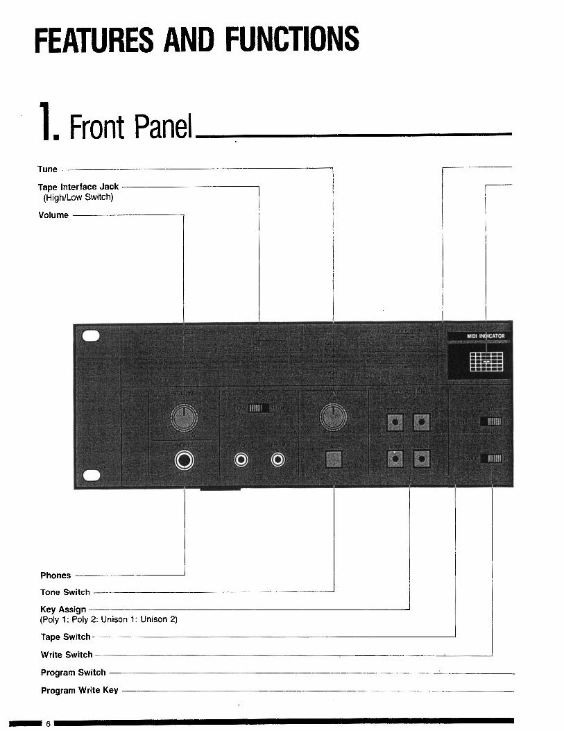
1. Front PanelTape Interface Jack
(lkgh/Low Switch)
Volume
Tune
1
Phones
Tone Switch
Key Assign(Poly 1: Poly 2: Unison 1: Unison 2)
Tape Switch
Write Switch
Program Switch
Program Write Key
-6

FEATURES&FUNCTIONS
Parameter List
MIDI Indicator
IndicatorsProgram No.Parameter No.Value
Power Switch
Value(Up/Down)
Number SelectButtons l-8
Parameter Switch
Bank Hold Switch

FEATURES & FUNCTIONS
1 .Rear Panel/Basic SetupAC Cord Receptacle I
MODEL EX-6000 UUL
AC 1OOV 50/60Hz 6W
lllllllllllllllllllllllllI AC cord

FEATURES 81 FUNCTIONS
MIDI Terminals: IN, OUT, THRU
OUTPUTfLow/High Switch, Left/Mono,kight) -
TO RAlN OR MOISTURE
0
SELECTING PROGRAMSThis explains how to select any of the 64 different sounds stored in the EX-8000’s memory. The PROGRAMMElsection on the front panel is used for this purpose.
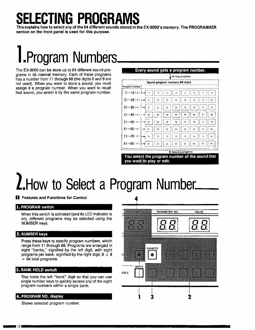
1Pn rogram NumbersThe EX-8000 can be store up to 64 different sound pro-grams in its” internal memory. Each of these programshas a number from 11 through 88 (the digits 0 and 9 are ,____----__--___-___-~ I
Writing programs- ----- - --------------- ~
not used). When you want to store a sound, you mustassign it a program number. When you want to recallthat sound, you select it by the same program number.
; - - - -I
----__--c-_- ---_____--_____ - - - - - ----_ - ------ _I
2.Hovv to Select a Program Numberq Features and Functions for Control
When this switch is activated (and its LED indicator ison), different programs may be selected using theNUMBER keys.
Press these keys to specify program numbers, whichrange from 11 through 88. Programs are arranged ineight “banks,” signified by the left digit, with eightprograms per bank, signified by the right digit; 8 x 8= 64 total programs.
This holds the left “bank” digit so that you can usesingle number keys to quickly access any of the eightprogram numbers within a single bank.
4
I I I1 3 2
Shows selected program number.
SELECTING PROGRAMS
q How to Select a Program Number
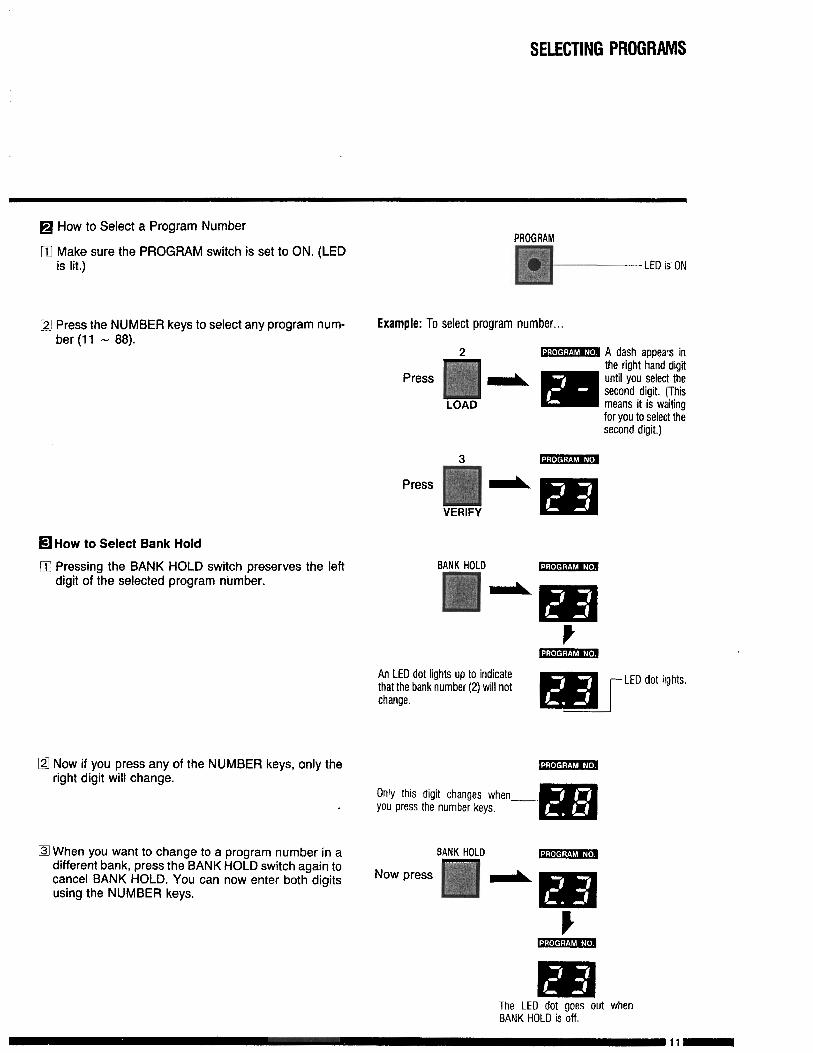
m fyi; sure the PROGRAM switch is set to ON. (LED
Q Press the NUMBER keys to select any program num-ber (11 - 88).
m How to Select Bank Hold
q Pressing the BANK HOLD switch preserves the leftdigit of the selected program number.
q Now if you press any of the NUMBER keys, only theright digit will change.
q When you want to change to a program number in adifferent bank, press the BANK HOLD switch again tocancel BANK HOLD. You can now enter both digitsusing the NUMBER keys.
PROGRAM
p+-.---LED IS ON
Example: To select program number...
3 . ‘,,V . , * A dash aooears inthe right hand digit
P ress until you select thesecond digit. (This
LOAD means it is waiting--.for you to select thesecond digit.)
BANK HOLD ..* . . ,
An LED dot lights up to indicatethat the bank number (2) will notchange.
m[LED d o t lights.
Only this digit changes whenyou press the number keys.
BANK HOLD
Now p ress
The LED dot goes out whenBANK HOLD is off.
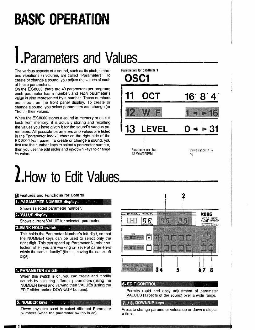
. Parameters and ValuesThe various aspects of a sound, such as its pitch, timbreand variations in volume, are called “Parameters”. Tocreate or change a sound, you adjust the values of eachof these parameters.On the EX-8000, there are 49 parameters per program;each parameter has a number, and each parameter’svalue is also represented by a number. These numbersare shown on the front panel display. To create orchange a sound, you select parameters and change (or“Edit”) their values.
When the EX-8000 stores a sound in memory or calls itback from memory, it is actually storing and recallingthe values you have given it for the sound’s various pa-rameters. All possible parameters and values are listedin the “parameter index” chart on the right side of theEX-8000 front panel. To create or change a sound, youfirst use the number keys to select a parameter number,then you use the edit slider and up/down keys to changeits value.
Parameters for oscillator 1
OSCl
16’ 8’ 4’
12 WAVEFORMValue range: 1 -16
.How to Edit Valuesq Features and Functions for Control
Shows selected parameter number.
Shows current VALUE for selected parameter.
This holds the Parameter Number’s left digit, so thatthe NUMBER keys can be used to select only theright digit. This can speed up Parameter Number se-lection when you are working on several parameterswithin the same “family” (that is, having the same leftdigit).
When this switch is on, you can create and modifysounds by selecting different parameters (using theNUMBER keys) and varying their VALUES (using theEDIT slider and/or DOWN/UP buttons). Permits rapid and easy adjustment of parameter
VALUES (aspects of the sound) over a wide range.
These keys are used to select different ParameterNumbers (when the parameter switch is on).
Press to change parameter values up or down a step ata time.
q How to Edit Values
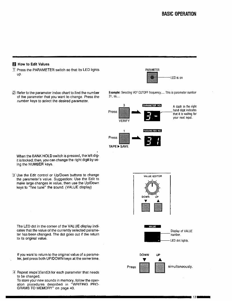
0 Press the PARAMETER switch so that its LED lightsup.
PARAMETERS
p+-LEO is on
@I Refer to the parameter index chart to find the numberof the parameter that you want to change. Press thenumber keys to select the desired parameter.
Example: Selecting VCF CUTOFF frequency.... This is parameter number31, so....
3 A dash in the right
1Press
TAPE) SAVE.
When the BANK HOLD switch is pressed, the left dig-it is locked; then, you can change the right digit by us-ing the NUMBER keys.
q Use the Edit control or Up/Down buttons to changethe parameter’s value. Suggestion: Use the Edit tomake large changes in value, then use the Up/Downkeys to “fine tune” the sound. (VALUE display)
The LED dot in the corner of the VALUE display indi-cates that the value of the currently selected parame-ter has been changed. The dot goes out if the returnto its original value.
If you want to return to the original value of a parame-~ ter, just press both UP/DOWN keys at the same time.
0 Repeat steps Band Ofor each parameter that needsto be changed.To store your new sounds in memory, follow the oper-ation procedures described in “WRITING PRO-GRAMS TO MEMORY” on page 40.
I VALUE EDITOR I
DOWN UP
v A
press :;;!I’;:-‘;m m simultaneously.
BASIC OPERATION
$.Tuning Procedureq Features and Functions for Control
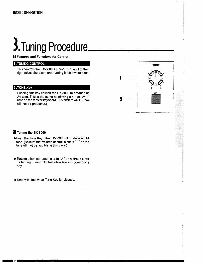
This controls the EX-8000’s tuning. Turning it to theirright raises the pitch, and turning it left lowers pitch.
1
Pushing this key causes the EX-8000 to produce anA4 tone. This is the same as playing a 4th octave Anote on the master keyboard. (A standard 440Hz tone 2will not be produced.)
q Tuning the EX-8000
0 Push the Tone Key. The EX-8000 will produce an A4tone. (Be sure that volume control is not at “0” as thetone will not be audible in this case.)
l Tune to other instruments or to “A” on a strobe tunerby turning Tuning Control while holding down ToneKey.
I
ITUNE
b tI
A 4
@Tone will stop when Tone Key is released.
MIDI
1 .MIDI ParametersThe EX-8000 operates according to MIDI data transmitted from external sources. In order to receivethis external data, it is necessary to make sure that the EX-8000 Receive channel is the same as thetransmitting channel. It is also necessary to set the EX-8000’s Key Window function. If this is notdone correctly, proper operation will be impossible. Care must be taken in setting MIDI-related pa-rameters.
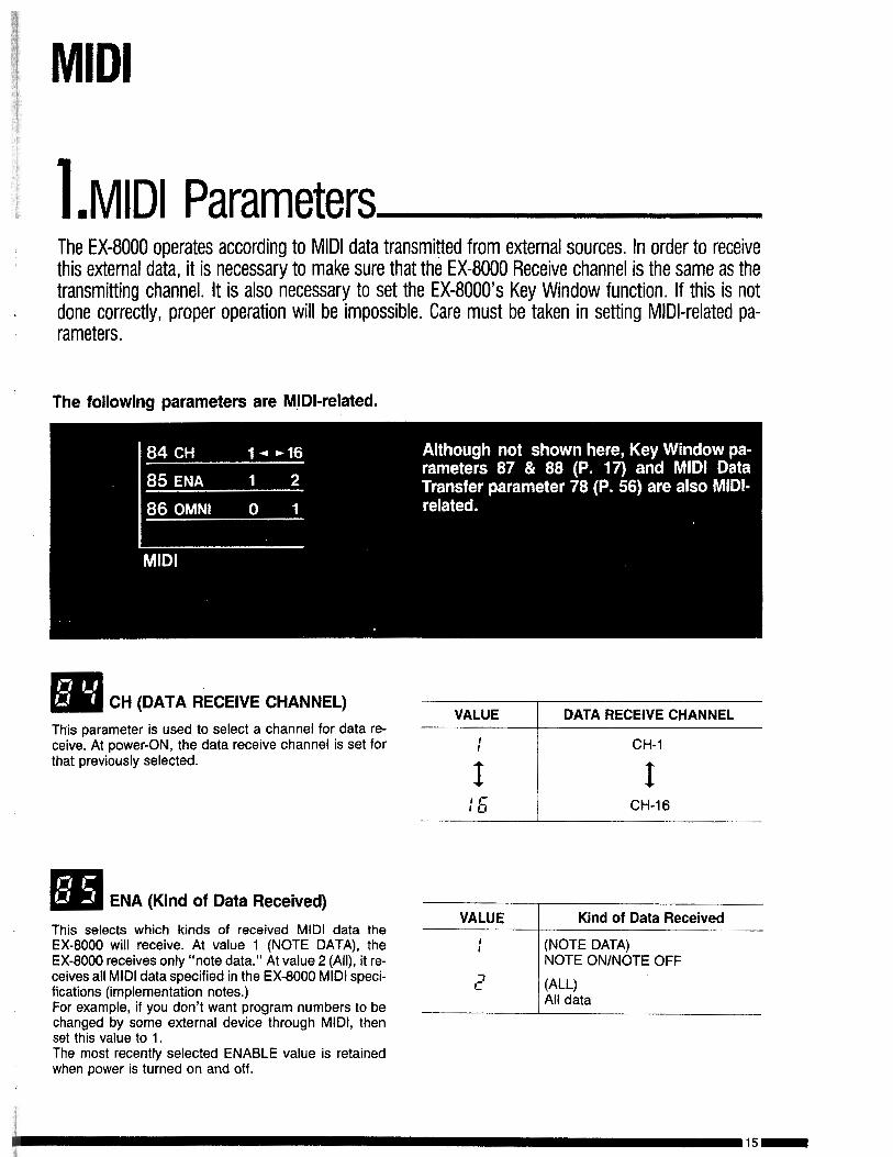
The following parameters are MIDI-related.
q CH (DATA RECEIVE CHANNEL) __VALUE 1 DATA RECEIVE CHANNEL
This parameter is used to select a channel for data re-ceive. At power-ON, the data receive channel is set forthat previously selected.
: CH-1
I I: !5 I CH-16
q ENA (Kind of Data Received)
This selects which kinds of received MIDI data theVALUE Kind of Data Received
EX-8000 will receive. At value 1 (NOTE DATA), theEX-8000 receives only “note data.” At value 2 (All), it re-ceives all MIDI data specified in the EX-8000 MIDI speci-fications (implementation notes.)For example, if you don’t want program numbers to bechanged by some external device through MIDI, thenset this value to 1.
: (NOTE DATA)NOTE ON/NOTE OFF
1: VWAll data
The most recently selected ENABLE value is retainedwhen power is turned on and off.
MIDI
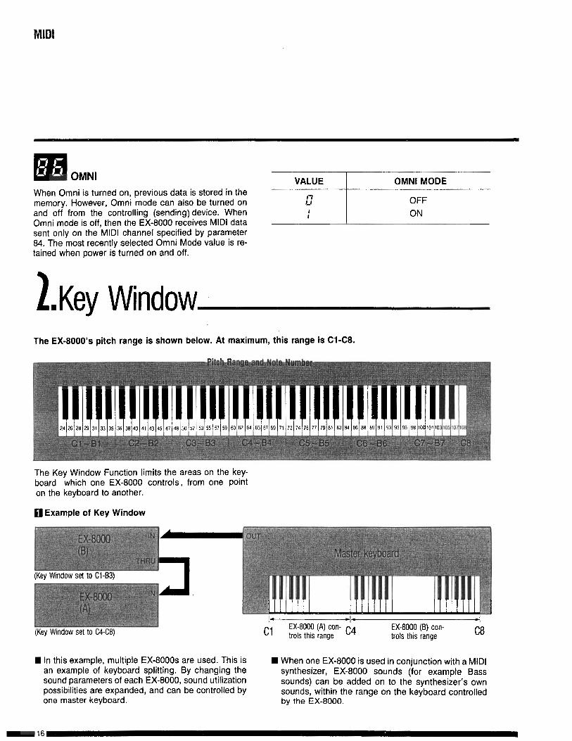
li!ill OMNI VALUE OMNI MODEWhen Omni is turned on, previous data is stored in thememory. However, Omni mode can also be turned onand off from the controlling (sending) device. WhenOmni mode is off, then the EX-8000 receives MIDI datasent only on the MIDI channel specified by parameter84. The most recently selected Omni Mode value is re-tained when power is turned on and off.
2 OFFON:
l.Key WindowThe EX-8000’s pitch range is shown below. At maximum, this range is Cl-C8.
The Key Window Function limits the areas on the key-board which one EX-8000 controls, from one pointon the keyboard to another.
fl Example of Key Window
EX-8000 (B) con-trols this range C8
n In this example, multiple EX-8000s are used. This is H When one EX-8000 is used in conjunction with a MIDIan example of keyboard splitting. By changing thesound parameters of each EX-8000, sound utilization
synthesizer, EX-8000 sounds (for example Bass
possibilities are expanded, and can be controlled bysounds) can be added on to the synthesizer’s own
one master keyboard.sounds, within the range on the keyboard controlledby the EX-8000.
MIDI
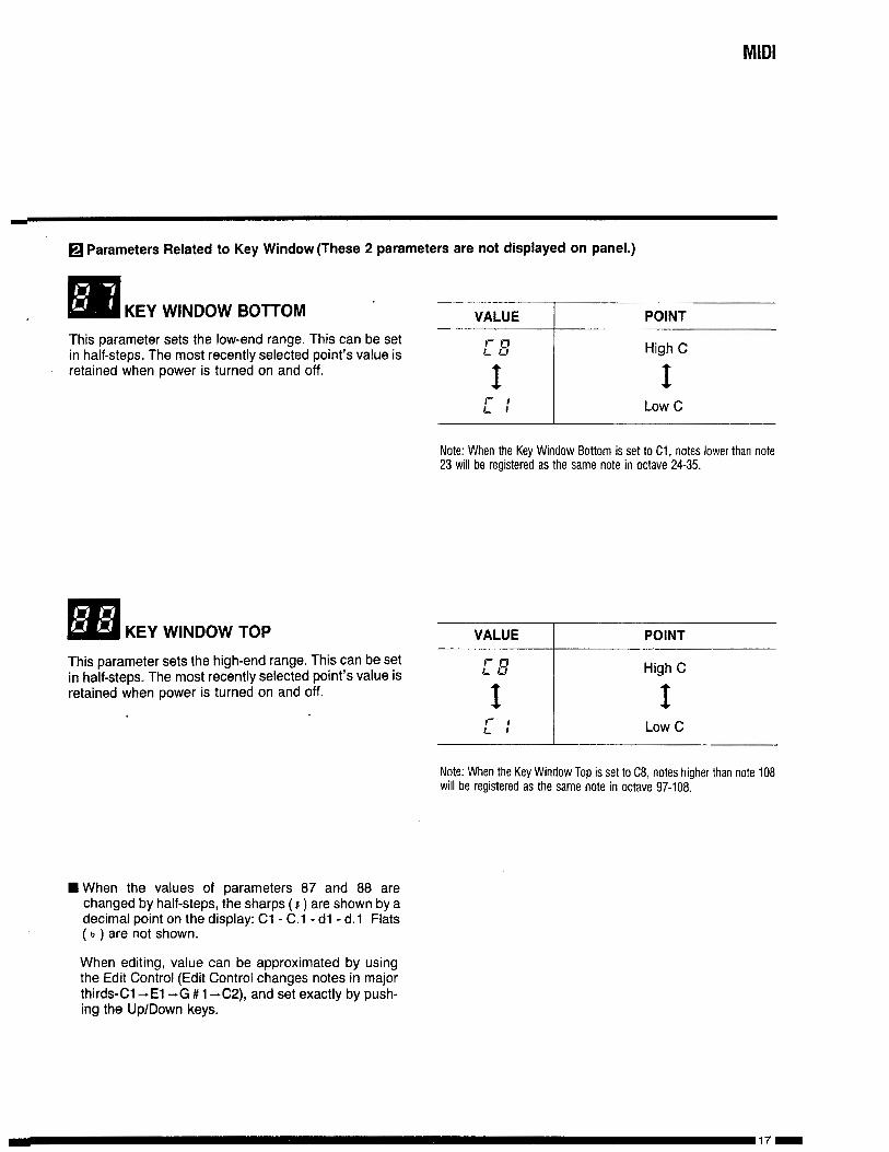
8 Parameters Related to Key Window (These 2 parameters are not displayed on panel.)
, q ’KEY WINDOW BOTTOM VALUE POINT
This parameter sets the low-end range. This can be setin half-steps. The most recently selected point’s value isretained when power is turned on and off.
q KEY WINDOW TOP VALUE I POINT
Note: When the Key Window Bottom is set to Cl, notes lower than note23 will be registered as the same note in octave 24-35.
This parameter sets the high-end range. This can be setin half-steps. The most recently selected point’s value isretained when power is turned on and off.
H i g h C
I
Note: When the Key Window Top is set to CB, notes higher than note 1013will be registered as the same note in octave 97-108.
n When the values of parameters 87 and 88 arechanged by half-steps, the sharps (1) are shown by adecimal point on the display: Cl - C.l - dl - d.1 Flats( b ) are not shown.
When editing, value can be approximated by usingthe Edit Control (Edit Control changes notes in majorthirds-Cl -El -G # 1 -C2), and set exactly by push-ing the Up/Down keys.
MIDI
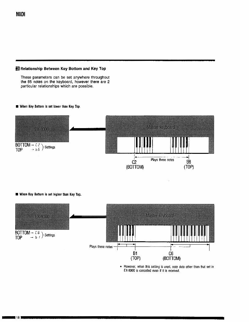
Eil Relationship Between Key Bottom and Key Top
These parameters can be set anywhere throughoutthe 85 notes on the keyboard, however there are 2particular relationships which are possible.
H When Key Bottom is set lower than Key Top.
Plays these notes
n When Key Boltom is se! higher than Key Top.
Plays these notes
* However, when this setting is used, note data other than that set inEX-BOO0 is cancelled even if it is received.
MIDI
3 .Transmitted/ReceivedMIDI Data and MIDI Indicators
0 Received MIDI Data
W Note OFFn Note ONn Control change:
No. 1 OSC modulationNo. 2 VCF modulationNo. 7 VdlumeNo. 64 Damper pedal on/offNo. 65 Portamento on/off
H Program changen Channel pressure (After Touch)W Pitch bender changen All notes OFFn Omni MODE OFFn Omni MODE ONn Active sensingH System exclusive information
q Transmitted MIDI Data
n Program ChangeWystem Exclusive Messages
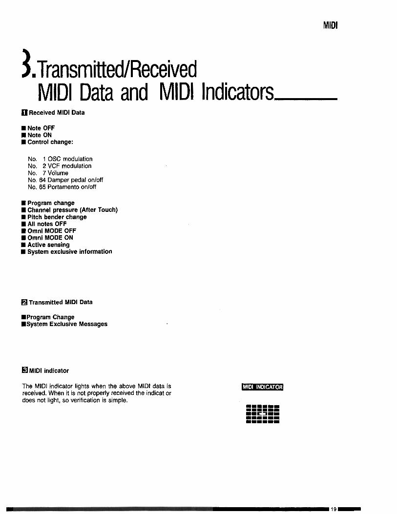
q MIDI indicator
The MIDI indicator lights when the above MIDI data isreceived. When it is not properly received the indicat ordoes not light, so verification is simple.
MIDI
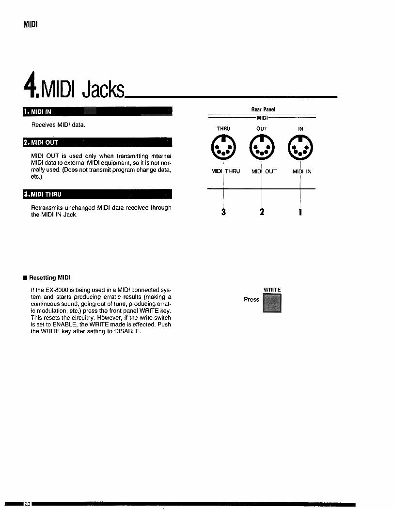
4.MIDI JacksD
Receives MIDI data.THRU
Rear PanelMIDI
OUT IN
MIDI OUT is used only when transmitting internalMIDI data to external MIDI equipment, so it is not nor-mally used. (Does not transmit program change data, I I I
MIDI, THRU MIDI OUT MIDI INetc.)
Retransmits unchanged MIDI data received throughthe MIDI IN Jack. i
q Resetting MIDI
If the EX-8000 is being used in a MIDI connected sys-tem and starts producing erratic results (making acontinuous sound, going out of tune, producing errat-ic modulation, etc.) press the front panel WRITE key.This resets the circuitry. However, if the write switchis set to ENABLE, the WRITE made is effected. Pushthe WRITE key after setting to DISABLE.
WRITE
Press

CREATING SOUNDS
1 .~ound Synthesis TechniquesTo create new sounds on the EX-8000, you change oredit old programs. You do not start with a “blank slate”.There are 64 sounds already in memory. If you have anew sound in mind, the easiest approach is to first se-lect a sound that resembles the sound you want to cre-ate. Then “edit” (change the selected sound until youget the sound you want. If you don’t find a similar sound,
it doesn’t matter; start with any sound you like.)After you finish editing your sound, you store it intomemory. At this point you can give it a different programnumber (thereby preserving the sound you started with)or the same program (thereby erasing or “overwriting”the old sound). (See page 40 Program Write)
,Z.Parameters Stored in MemoryThis section describes parameters which can be stored in the EX-8000’s memory to create yoursounds.q 0SC.l
q OCT
Here you select the basic pitch range of oscillator 1. Thehigher the value, the lower the pitch. You have threechoices which correspond to 16’ (16 foot), 8’, 4’.
CREATING SOUNDS
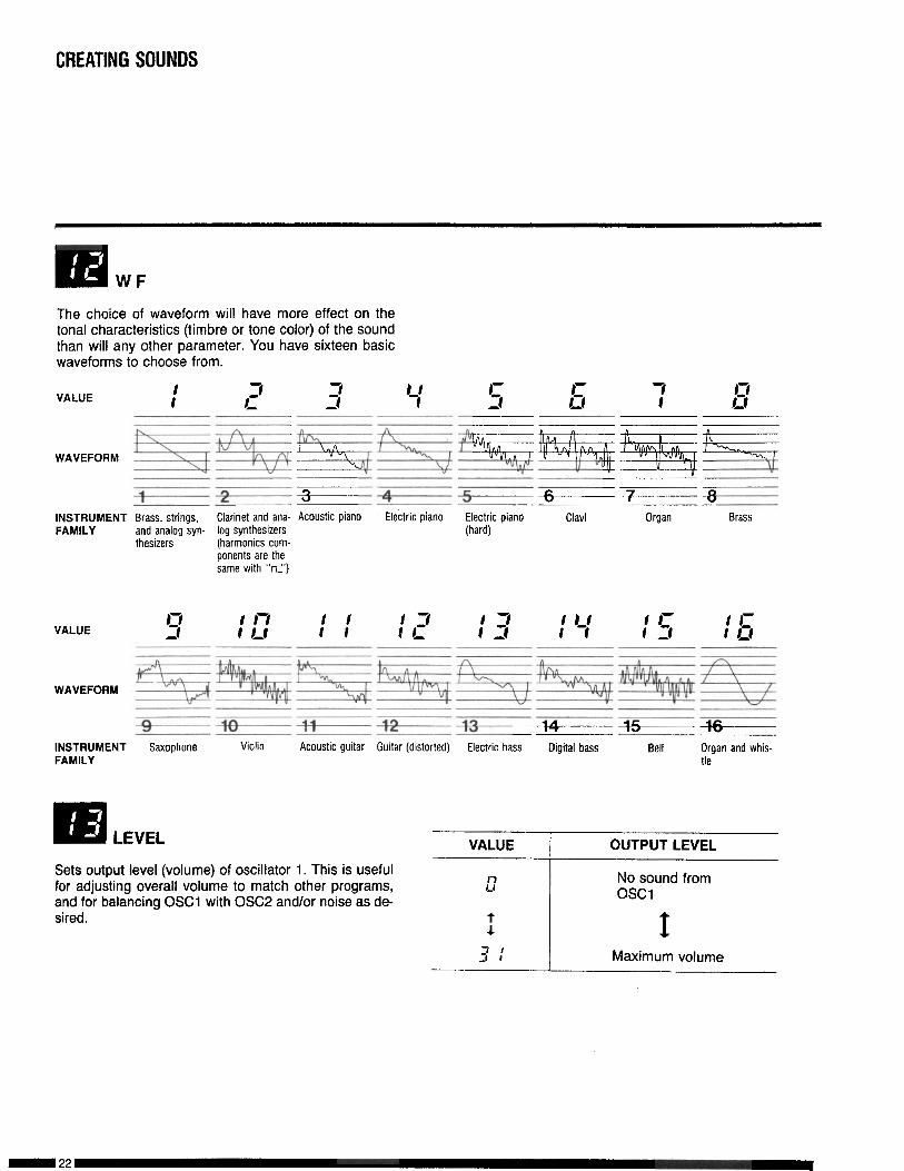
m WF
The choice of waveform will have more effect on thetonal characteristics (timbre or tone color) of the soundthan will any other parameter. You have sixteen basicwaveforms to choose from.
VALUE 3I-
n
fC-.WAVEFORM r
11
-~~zF-----+-s------+-
INSTRUMENT Brass, strings, Clarinet and ana- Acoustic piano Electric piano Electric piano Clavi Organ BrassFAMILY and analog syn- log synthesizers (hard)
thesizers (harmonics com-ponents are thesame with “nL’)
VALUE
WAVEFORM
INSTRUMENTFAMILY
+----+Saxophone Violin Acoustic guitar
+&----4++----b-Guitar (distorted) Electric bass Digital bass Bell
r’ b
Organ and whis-tle
Ra LEVEL VALUE OUTPUT LEVEL
Sets output level (volume) of oscillator 1. This is usefulfor adjusting overall volume to match other programs,and for balancing OSCl with OSC2 and/or noise as de-sired.
L7
I
3 :
No sound fromosci
IMaximum volume
CREATING SOUNDS
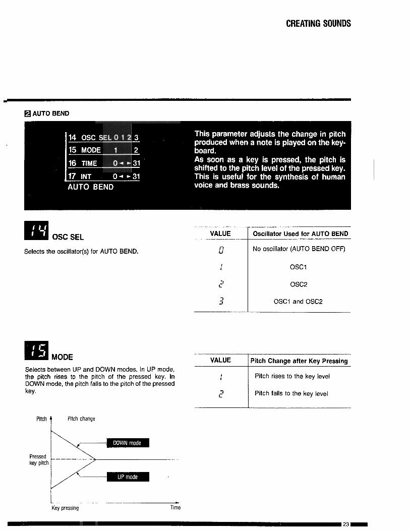
OSC SEL
Selects the oscillator(s) for AUTO BEND.
Oscillator Used for AUTO BEND
No oscillator (AUTO BEND OFF)
OSCl
osc2
OSCl and OSC2
BE! MODE VALUE Pitch Change after Key PressingSelects between UP and DOWN modes. In UP mode,the pitch rises to the pitch of the pressed key. InDOWN mode, the pitch falls to the pitch of the pressedkey.
Pitcht
Pitch change
P r e s s e dkey pitch
IKey pressing
cTime
23-

TIME
Sets a period of time from the key pressing to the timewhen the pitch reaches the pitch of the pressed key.
VALUETime Period from Key Pressingto the Pitch’s Reaching the KeyLevel
Pitch
Pressedkey pitch
Key pressing Titne
El INT
Specifies the pitch where pitch change starts.VALUE
I7l-1
I7 I3 ,
Pitch Change width
No pitch change(AUTO BEND OFF)
IMax. bend width
(2 octave)
Key pressing Time
CREATING SOUNDS
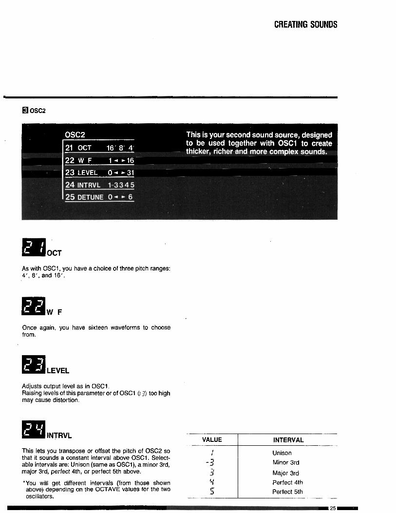
lmOCT
As with OSCl , you have a choice of three pitch ranges:4’, 8’, and 16’.
Once again, you have sixteen waveforms to choosefrom.
Adjusts output level as in OSCi.Raising levels of this parameter or of OSCl 0 3) too highmay cause distortion.
lm INTRVL VALUE INTERVAL
This lets you transpose or offset the pitch of OSC2 sothat it sounds a constant interval above OSCl. Select-able intervals are: Unison (same as OSCl), a minor 3rd,major 3rd, perfect 4th, or perfect 5th above.
*You will get different intervals (from those shownabove) depending on tne OCTAVE WUeS for the twooscillators.
UnisonMinor 3rd
Major 3rdPerfect 4thPerfect 5th
CREATING SOUNDS
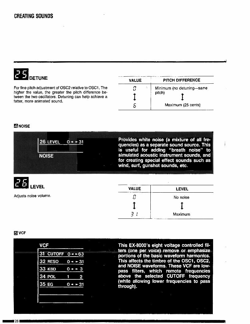
For fine pitch adjustment of OSC2 relative to OSCl. Thehigher the value, the greater the pitch difference be-tween the two oscillators. Detuning can help achieve afatter, more animated sound.
VALUE PITCH DIFFERENCE
L7 Minimum (no detuning-same
I pitch) Is Maximum (25 cents)
q NOISE
‘rn LEVEL VALUE LEVEL
Adjusts noise volume.
q VCF
CREATING SOUNDS
VALUE TIMBRE
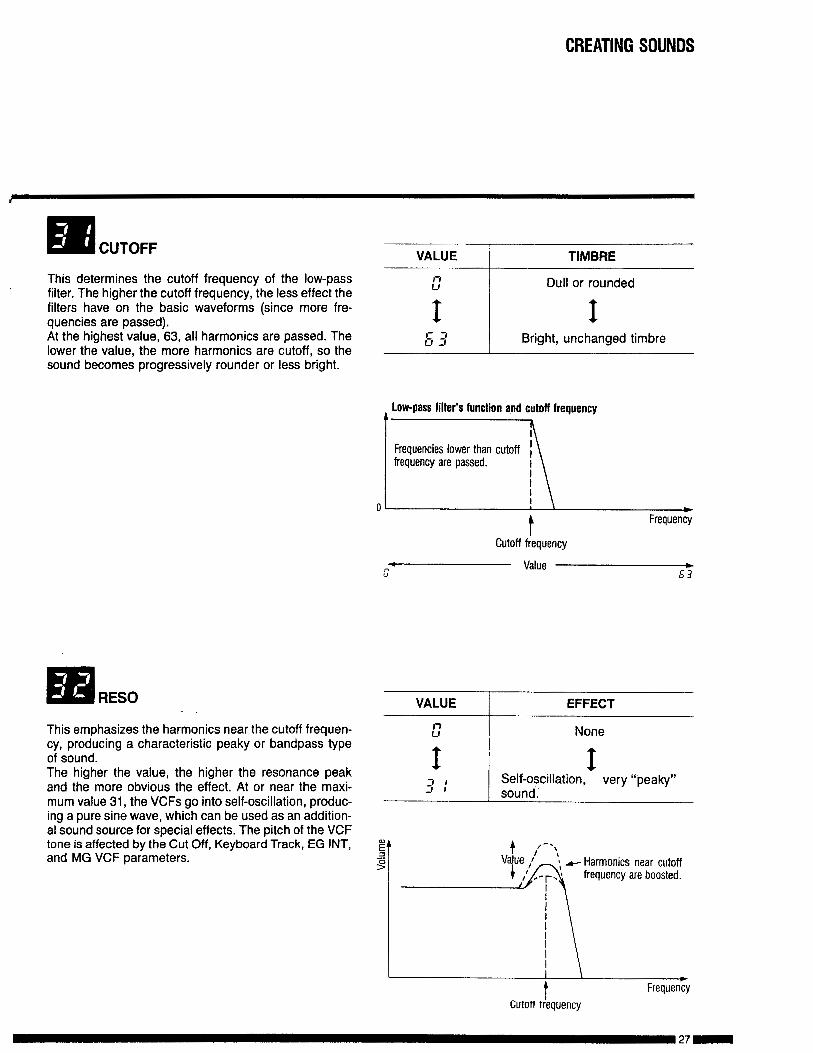
This determines the cutoff frequency of the low-passfilter. The higher the cutoff frequency, the less effect thefilters have on the basic waveforms (since more fre-quencies are passed).At the highest value, 63, all harmonics are passed. Thelower the value, the more harmonics are cutoff, so thesound becomes progressively rounder or less bright.
This emphasizes the harmonics near the cutoff frequen-cy, producing a characteristic peaky or bandpass typeof sound.The higher the value, the higher the resonance peakand the more obvious the effect. At or near the maxi-mum value 31, the VCFs go into self-oscillation, produc-ing a pure sine wave, which can be used as an addition-al sound source for special effects. The pitch of the VWtone is affected by the Cut Off, Keyboard Track, EG INT,and MG VCF parameters.
Low-pass filter’s function and cutoff frequencyta
Frequencies lower than cutoff Ifrequency are passed.
,
\
0
II
tCutoff frequency
bFrequency
Value c53
VALUE
l-lLl
EFFECT
None
;I:1 ~$fnodscillation~ v e r y “pesky”
Harmonics near cutofffrequency are boosted.
cFrequency
Cutoff frequency
CREATING SOUNDS
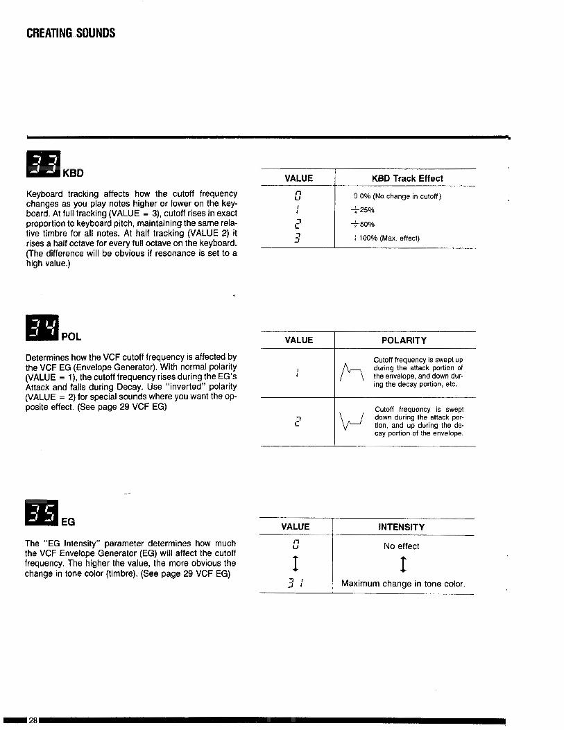
Keyboard tracking affects how the cutoff frequencychanges as you play notes higher or lower on the key-board. At full tracking (VALUE = 3), cutoff rises in exactproportion to keyboard pitch, maintaining the same rela-tive timbre for all notes. At half tracking (VALUE 2) itrises a half octave for every full octave on the keyboard.(The difference will be obvious if resonance is set to ahigh value.)
VALUE KBD Track Effect
c 0 0% (No change in cutoff)
: +25%
I? t50%
3 I 100% (Max. effect)
5lPOL
Determines how the VCF cutoff frequency is affected bythe VCF EG (Envelope Generator). With normal polarity(VALUE = l), the cutoff frequency rises during the EG’sAttack and falls during Decay. Use “inverted” polarity(VALUE = 2) for special sounds where you want the op-posite effect. (See page 29 VCF EG)
VALUE POLARITY
P-7L-J
Cutoff frequency is swept upduring the attack portion ofthe envelope, and down dur-ing the decay portion, etc.
Cutoff frequency is sweptdown during the attack por-tion, and up during the de-cay portion of the envelope.
q EG VALUE fNTENSlTY
The “EG Intensity” parameter determines how much I7U
the VCF Envelope Generator (EG) will affect the cutofffrequency. The higher the value, the more obvious thechange in tone color (timbre). (See page 29 VCF EG) I
3 :
No effect
IMaximum change in tone color.
CREATING SOUNDS
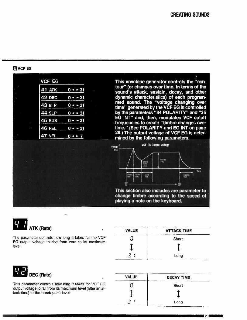
q VCF EG
q ATK (Rate) . VALUE ATTACK TIME
The parameter controls how long it takes for the VCFEG output voltage to rise from zero to its maximumlevel.
VALUE DECAY TIME
This parameter controls how long it takes for VCF EGoutput voltage to fall from its maximum level (after an at-tack time) to the break point level.
E Short
I I3 : Long
CREATING SOUNDS
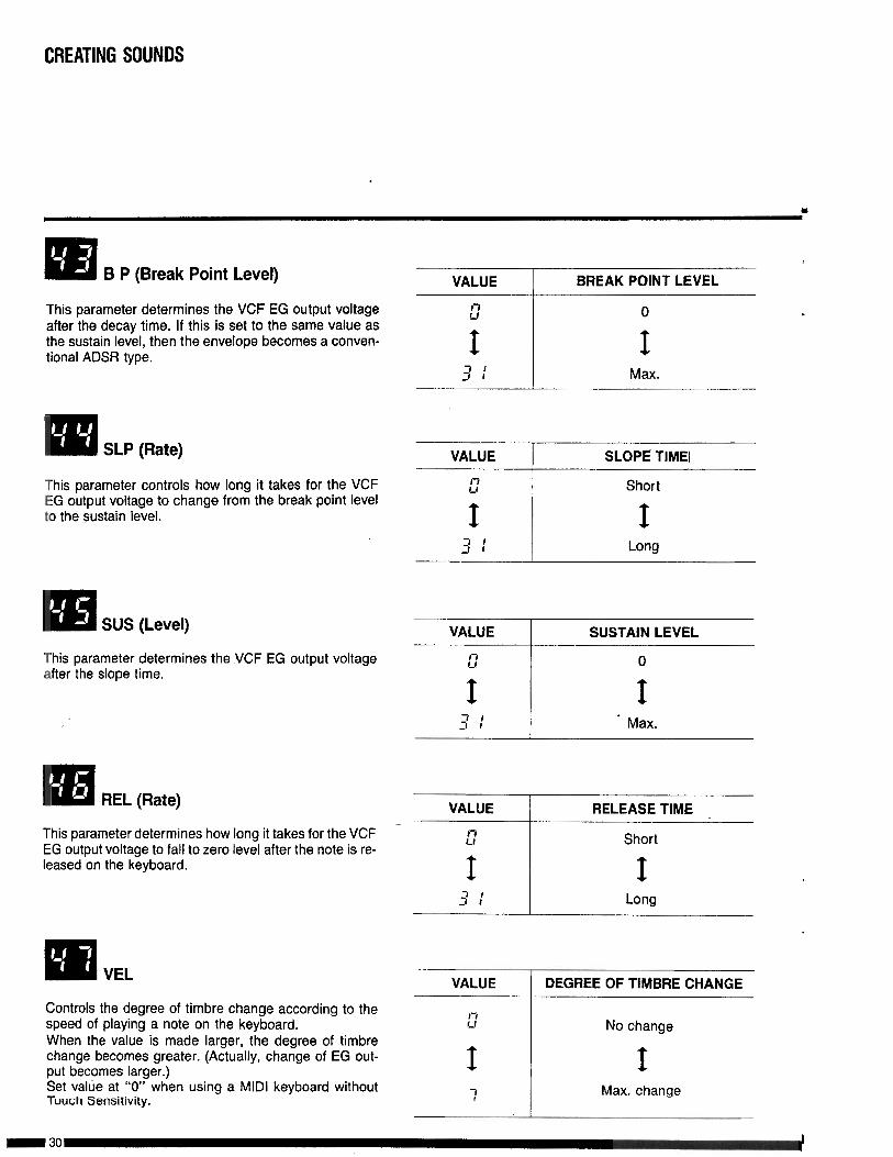
em B P (Break Point Level)
This parameter determines the VCF EG output voltageafter the decay time. If this is set to the same value asthe sustain level, then the envelope becomes a conven-tional ADSR type.
This parameter controls how long it takes for the VCFEG output voltage to change from the break point levelto the sustain level.
m SUS (Level)
This parameter determines the VCF EG output voltageafter the slope time.
This parameter determines how long it takes for the VCFEG output voltage to fall to zero level after the note is re-leased on the keyboard.
Controls the degree of timbre change according to thespeed of playing a note on the keyboard.When the value is made larger, the degree of timbrechange becomes greater. (Actually, change of EG out-put becomes larger.)Set valtie at “0” when using a MIDI keyboard withoutTouch Sensitivity.
VALUE BREAK POINT LEVEL
I7(J 0
VALUE 1 SLOPE TIME1
VALUE
l-ll-l
I3 IJ I
SUSTAIN LEVEL
0
IMax.
VALUE
::
I3:
RELEASE TIME
Short
ILong
VALUE 1 DEGREE OF TIMBRE CHANGE
Max. change
.
CREATINGSOUNDS
Ex: When the value is changed for a fixed envelope.A
~-Valve set to 7.
Valve set to 3.
Value set to “0”. (No change)
Time
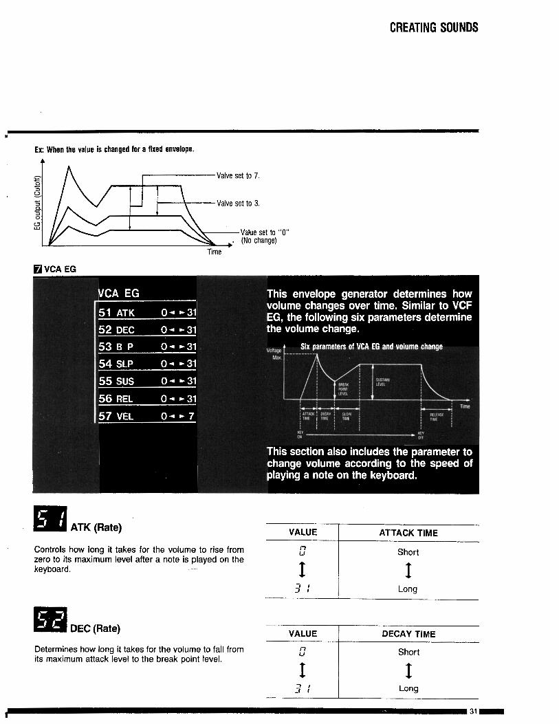
RVCA EG
m ATK (Rate) VALUE ATTACK TIME
Controls how long it takes for the volume to rise fromzero to its maximum level after a note is played on thekeyboard.
VALUE I DECAY TIME
Determines how long it takes for the volume to fall fromits maximum attack level to the break point level.
I!.: Short
t t1 13; Long
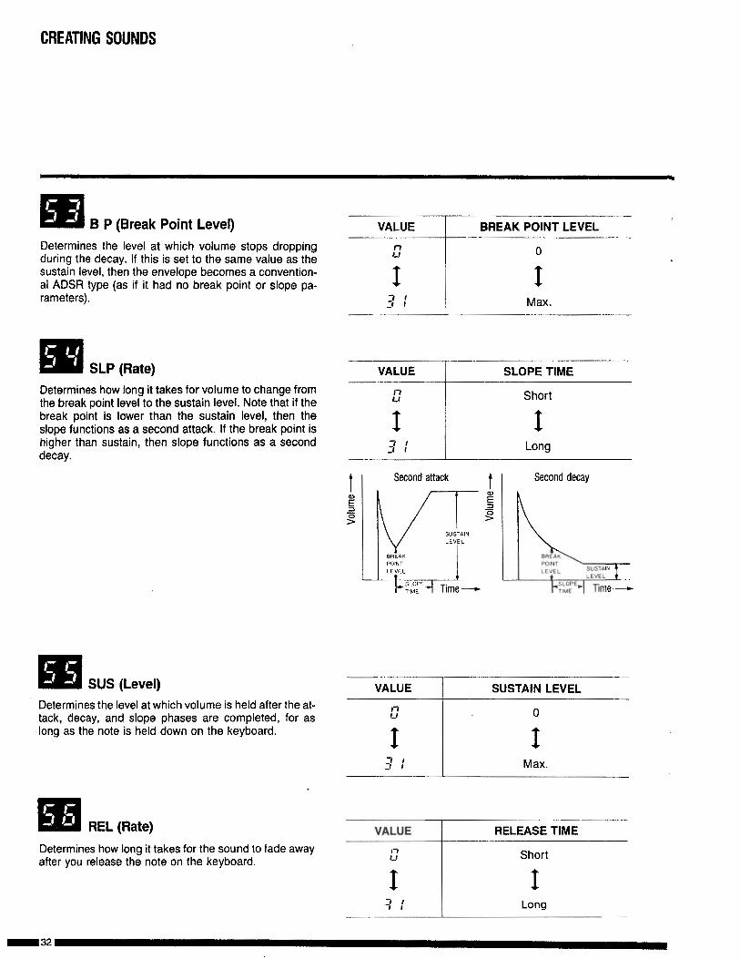
q B P (Break Point Level) VALUE BREAK POINT LEVEL
Determines the level at which volume stops droppingduring the decay. If this is set to the same value as thesustain level, then the envelope becomes a convention-al ADSR type (as if it had no break point or slope pa-rameters).
Determines how long it takes for volume to change fromthe break point level to the sustain level. Note that if thebreak point is lower than the sustain level, then theslope functions as a second attack. If the break point ishigher than sustain, then slope functions as a seconddecay.
VALUE
::
I3:
SLOPE TIME
Short
ILong
tE=t3I
Second attack Second decay
Determines the level at which volume is held after the at-tack, Uecay, and slope phases are completed, for aslong as the note is held down on the keyboard.
VALUE
::
I3 IJ I
SUSTAIN LEVEL
0
I
Max.
REL (Rate)Determines how long it takes for the sound to fade awayafter you release the note on the keyboard.
VALUE
I71-l
I-I I
3 I
RELEASE TIME
Short
ILong
CREATING SOUNDS
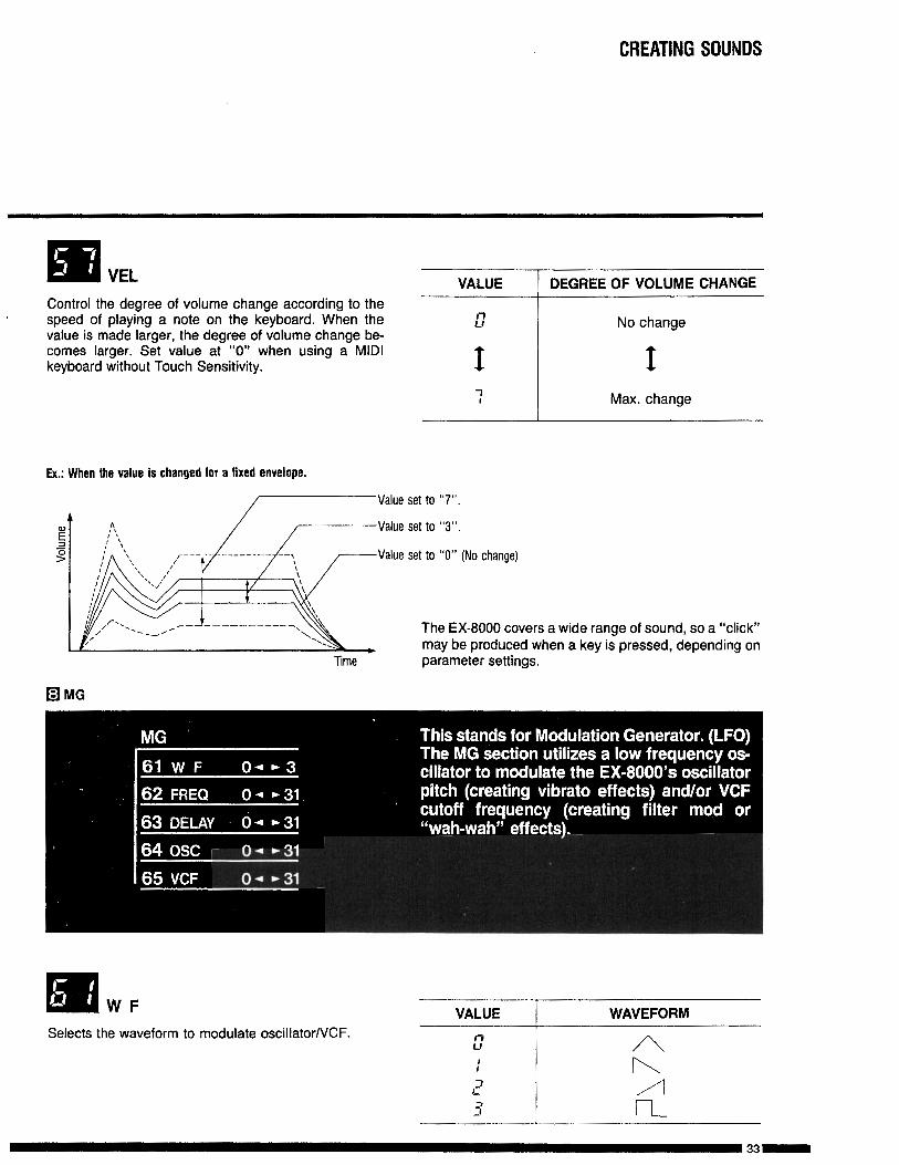
IiN VEL VALUE DEGREE OF VOLUME CHANGEControl the degree of volume change according to thespeed of playing a note on the keyboard. When thevalue is made larger, the degree of volume change be-comes larger. Set value at “0” when using a MIDIkeyboard without Touch Sensitivity.
No change
IMax. change
Ex.: When the value is changed for a fixed envelope.
Value set to “7”.
Value set to “3”.
Value set to “0” (No change)
Time
The EX-8000 covers a wide range of sound, so a “click”may be produced when a key is pressed, depending onparameter settings.
q MG
WFSelects the waveform to modulate oscillator/VCF.
VALUE I WAVEFORM
33-
CREATING SOUNDS
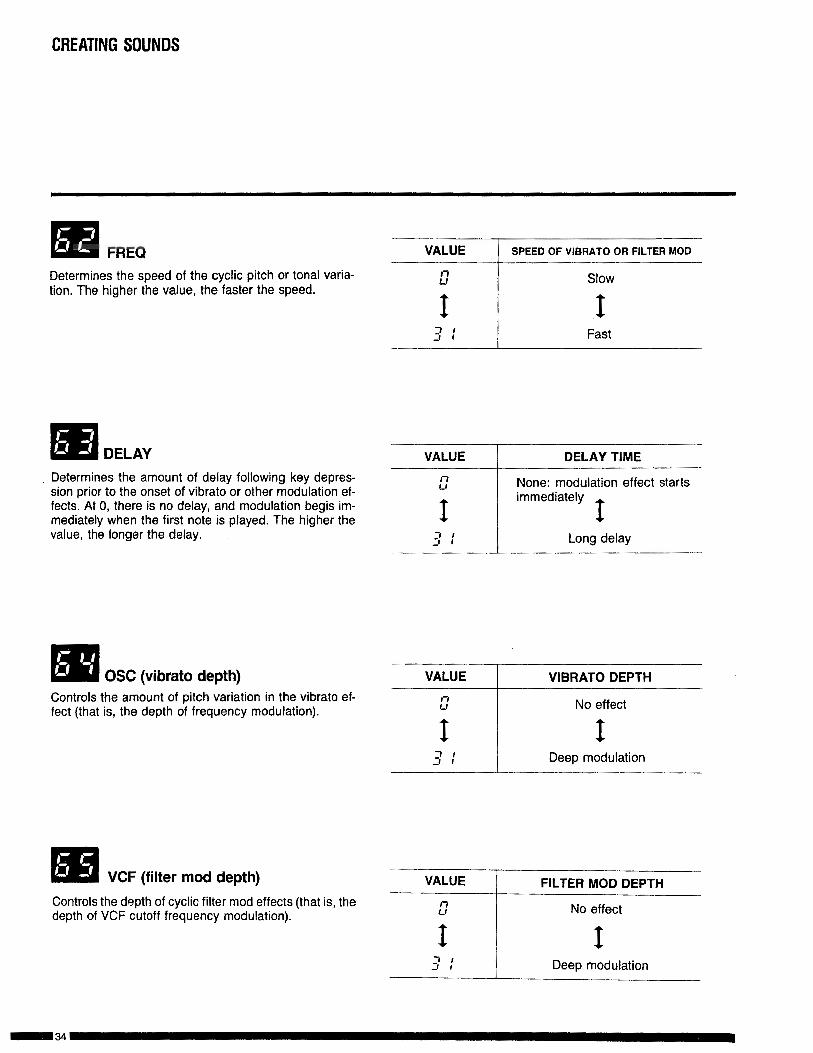
m FREQ VALUE SPEED OF VIBRATO OR FILTER MOD
Determines the speed of the cyclic pitch or tonal varia-tion. The higher the value, the faster the speed.
::
I7 I:I I
Slow
IFast
VALUE I DELAY TIME
Determines the amount of delay following key depres-sion prior to the onset of vibrato or other modulation ef-fects. At 0, there is no delay, and modulation begis im-mediately when the first note is played. The higher thevalue, the longer the delay.
None: modulation effect starts
OSC (vibrato depth)Controls the amount of pitch variation in the vibrato ef-feet (that is, the depth of frequency modulation).
VALUE
I71-l
I3:
VIBRATO DEPTH
No effect
IDeep modulation
m VCF (filter mod depth)Controls the depth of cyclic filter mod effects (that is, thedepth of VCF cutoff frequency modulation).
VALUE 1 FILTER MOD DEPTH
No effect
3 I-I I I Deep modulation
CREATING SOUNDS
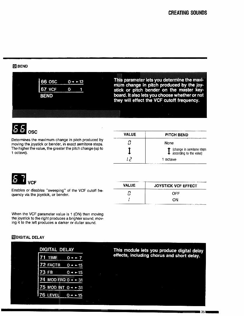
q BEND
oscDetermines the maximum change in pitch produced bymoving the joystick or bender, in exact semitone steps.The higher the value, the greater the pitch change (up to1 octave).
VALUE
2
I17I L
PITCH BEND
None
I (change in semitone stepsaccording to the value)
1 octave
Enables or disables “sweeping” of the VCF cutoff fre-quency via the joystick, or bender.
VALUE JOYSTICK VCF EFFECTl-lu OFF
: ON
When the VCF parameter value is 1 (ON) then movingthe joystick to the right produces a brighter sound; mov-ing it to the left produces a darker or duller sound.
fIl DIGITAL DELAY

CREATING SOUNDS
m TIME (Delay time) \VALUE DELAY TIME RANGE
Adjusts delay time coarsely. Fine adjustment is per-formed by using the FACTOR parameter.
About 2 - 4msAbout 4 - 8ms
About 8 - 16ms
About 16 - 32ms
About 32 - 64ms
About 64 - 128ms
About 128 - 256ms
About 256 - 512ms
!
FACTRPerforms fine adjustment of delay time in a range speci-fied by the TIME parameter (71).
: :I I (xl) Long
Controls feedback quantity.VALUE
l-l1-1
I: 5
FEEDBACK QUANTITY
0% (No feedback)
I100%
Ic1&l MOD FRQ (Modulation frequency) VALUE FREQUENCYDetermines the speed of the low-frequency oscillatoroutput used to modulate delay time. :: Slow
I3 1J 1I
Fast

CREATING SOUNDS
‘I! • a MOD INT (Modulation intensity)
6 Determines the modulation depth for delay time modula-tion.
VALUE MODULATION DEPTH
No modulation
ILarge
b
m LEVEL VALUE I LEVEL
Control the volume of effect sounds mixed in directsound (the sound without delay effect). I f
q PORTAMENTO
TIME (Portamento) VALUE PORTAMENTO TIMEDetermines how gradual the change in pitch is.
l-l!A
No portamento effect (instantchange)
3 :Slow change in pitch from onenote to the next.
CREATING SOUNDS
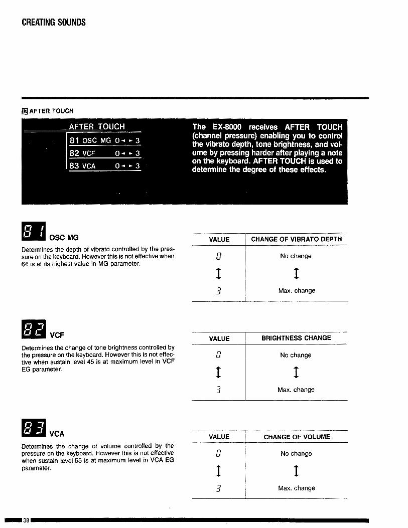
•j AFTER ToucH
q OSC MGDetermines the depth of vibrato controlled by the pres-sure on the keyboard. However this is not effective when64 is at its highest value in MG parameter.
3J Max. changeI
q VCF
Determines the change of tone brightness controlled bythe pressure on the keyboard. However this is not effec-tive when sustain level 45 is at maximum level in VCFEG parameter.
VALUE BRIGHTNESS CHANGE
I71-f
INo change
I3 ! Max. change
VALUE CHANGE OF VOLUMEDetermines the change of volume controlled by thepressure on the keyboard. However this is not effectivewhen sustain level 55 is at maximum level in VCA EGparameter.
3 I Max. change
7-7-.-.~--,
CREATING SOUNDS
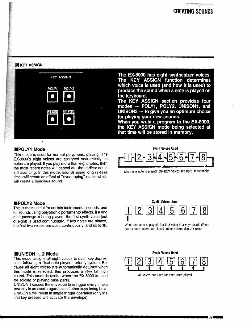
@ KEY ASSIGN
IIPOLYl ModeThis mode is used for normal polyphonic playing. TheEX-8000’s eight voices are assigned sequentially asnotes are played. If you play more than eight notes, thenthe most recent notes will cancel out the earliest notesstill sounding. In this mode, sounds using long releasetimes will create an effect of “overlapping” notes, whichwill create a spacious sound.
n POLY2 ModeThis is most useful for certain instrumental sounds, andfor sounds using polyphonic portamento effects. If a onenote passage is being played, the first synth voice (outof eight) is used continuously. If two notes are played,the first two voices are used continuously, and so forth.
WNISON 1,2 ModeThis mode assigns all eight voices to each key depres-sion, following a “last note played” priority system. Be-cause all eight voices are automatically detuned whenthis mode is selected, this produces a very fat, richsound. This mode is useful when the EX-8000 is usedfor soloing or playing bass parts.UNISON 1 causes the envelope to retrigger every time anew key is pressed, regardless of other keys being held.UNISON 2 wilt result in single trigger operation (only thefirst key pressed will activate the envelope).
Synth Voices Used
When one note is played, the eight voices are used sequentially.
Synth Voices Used
When one note is played, the first voice is always used. Whentwo or more notes are played, other voices also are used.
Synth Voices Used
All voices are used for each note played
CREATING SOUNDS
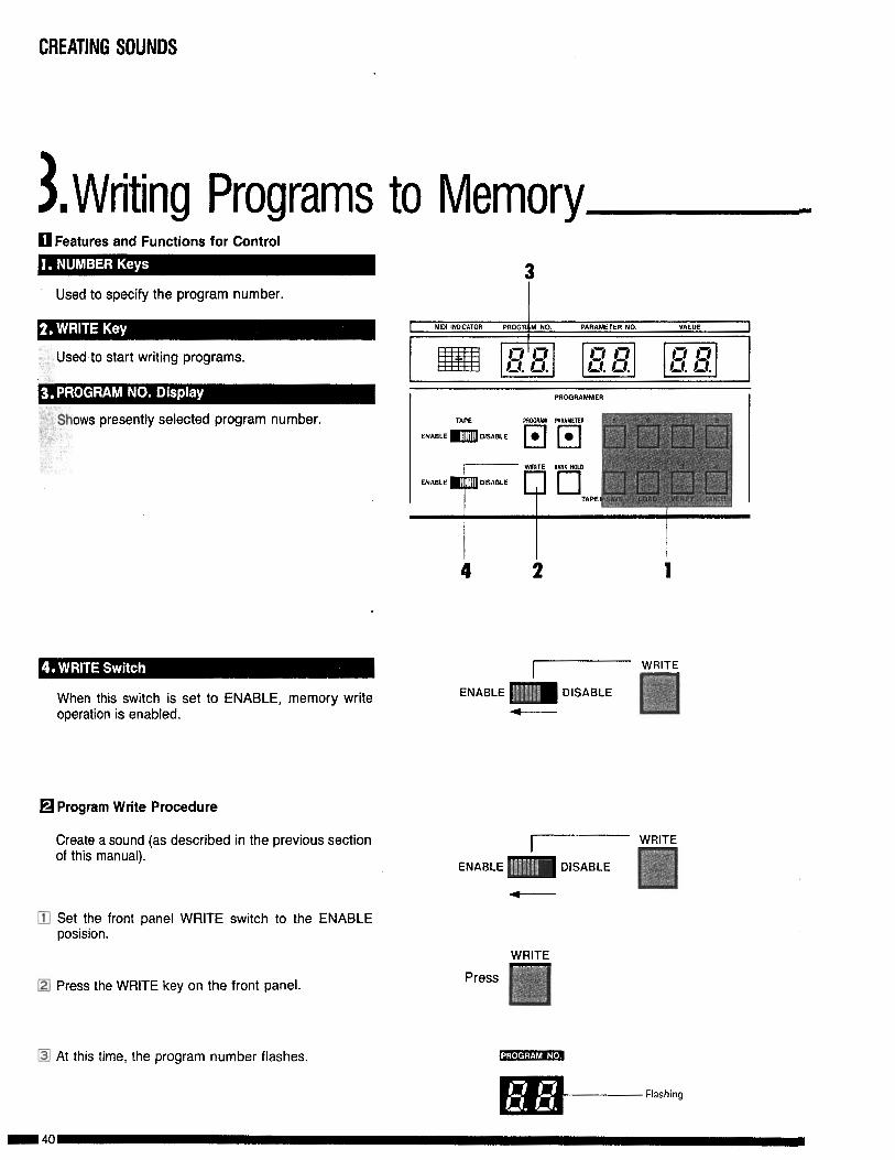
3, Writing Programs to MemoryJfl Features and Functions for Control
Used to specify the program number.
I
Used to start writing programs.
Shows presently selected program number.
When this switch is set to ENABLE, memory writeoperation is enabled.
q Program Write Procedure
Create a sound (as described in the previous sectionof this manual).
q Set the front panel WRITE switch to the ENABLEposision.
q Press the WRITE key on the front panel.
4
I----ENABLE m DISABLE
WRITE
m At this time, the program number flashes.
Flashing
CREATING SOUNDS
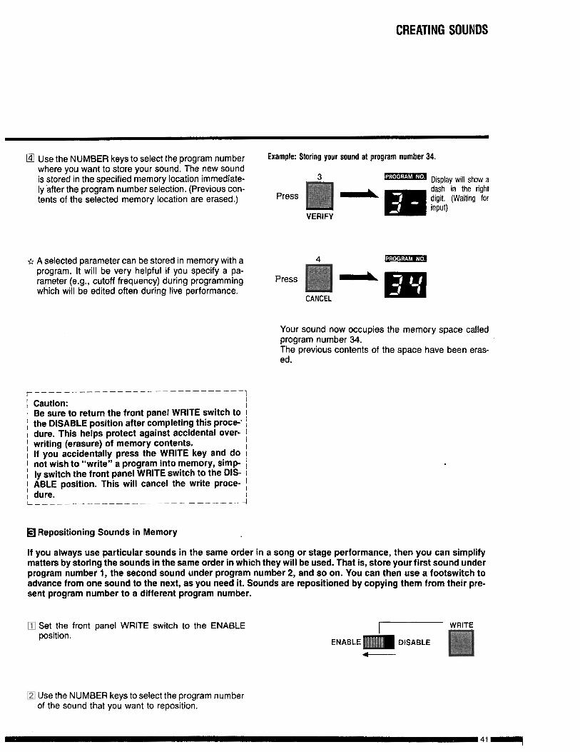
@I Use the NUMBER keys to select the program number Example: Storing your sound at program number 34.where you want to store your sound. The new soundis stored in the specified memory location immediate- 3 .‘, . . ,m Display will show aly after the program number selection. (Previous con-
- m
dash in the righttents of the selected memory location are erased.) Press digit. (Waiting for
input)VERIFY
sr A selected parameter can be stored in memory with aprogram. It will be very helpful if you specify a pa-rameter (e.g., cutoff frequency) during programmingwhich will be edited often during live performance.
4
Press
CANCEL
Your sound now occupies the memory space calledprogram number 34.The previous contents of the space have been eras-ed.
r - - - - - _ _ _ _ _ _ _ _ _ _ - _ _ _ - _ - - - _ - - -
[ Caution:1 Be sure to return the front panel WRITE switch to1 the DISABLE position after completing this proce-’I dure. This helps protect against accidental over-; writing (erasure) of memory contents.I If you accidentally press the WRITE key and do1 not wish to “write” a program into memory, simp-i ly switch the front panel WRITE switch to the DIS-; ABLE position. This will cancel the write proce-, dure.L-- --____-______ ---_-. --_----
‘1
-I
q Repositioning Sounds in Memory
If you always use particular sounds in the same order in a song or stage performance, then you can simplifymatters by storing the sounds in the same order in which they will be used. That is, store your first sound underprogram number 1, the second sound under program number 2, and so on. You can then use a footswitch toadvance from one sound to the next, as you need it. Sounds are repositioned by copying them from their pre-sent program number to a different program number.
0 Set the front panel WRITE switch to the ENABLEposition.
7
ENABLE m DISABLE4
D Use the NUMBER keys to select the program numberof the sound that you want to reposition.
CREATING SOUNDS
,
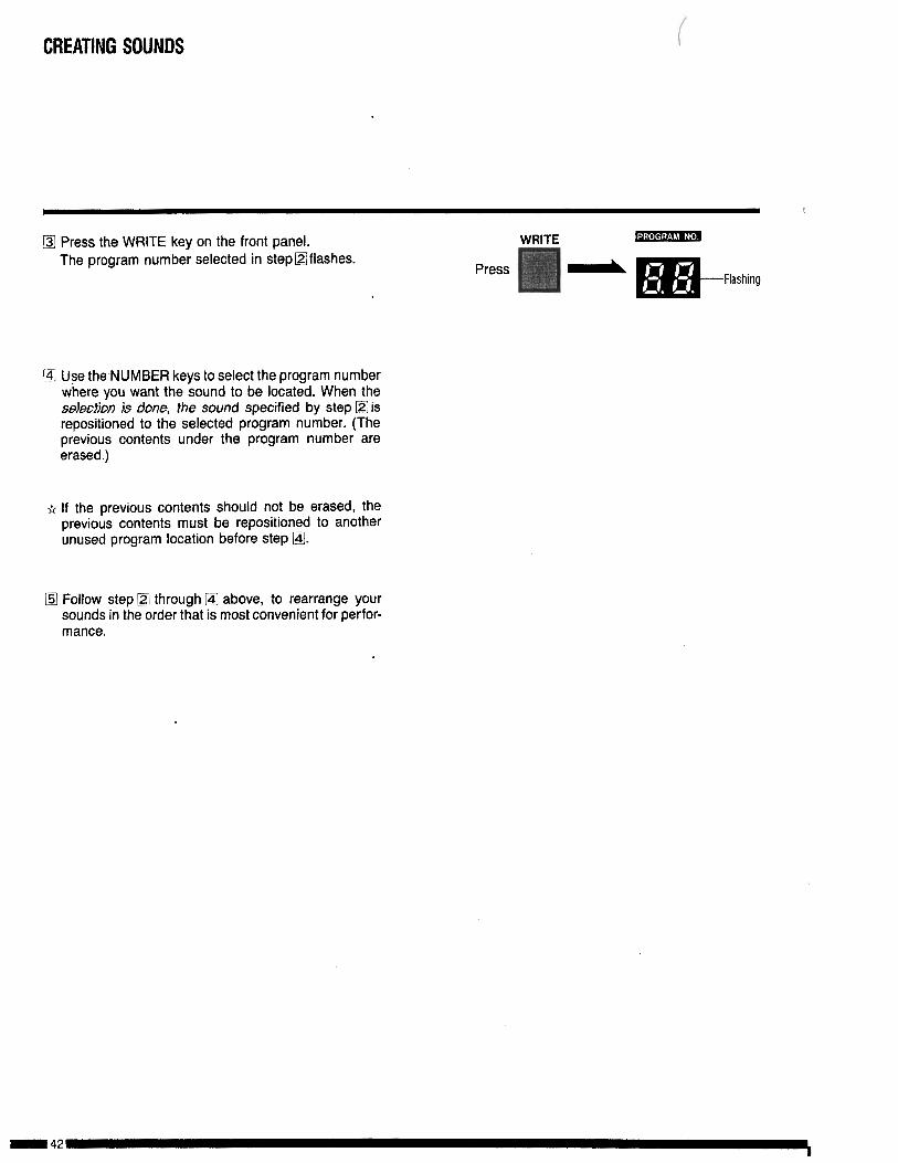
a Press the WRtTE key on the front panel.The program number selected in stepOflashes.
WRITE
Press-
1~ Use the,NUMBER keys to select the program numberwhere you want the sound to be located. When thes.electiDn j.s done, the sound specified by step m isrepositioned to the selected program number. (Theprevious contents under the program number areerased.)
fi If the previous contents should not be erased, theprevious contents must be repositioned to anotherunused program location before step @J.
L!Z Follow step @ through @ above, to rearrange yoursounds in the order that is most convenient for perfor-mance.

TAPE INTERFACE
The EX-8000 is equipped with a tape interface that lets you SAVE all sound data stored in memory oncassette tape. Later you can LOAD the data from the tape back into the EX-8000’s internal memory.,A wide variety of sound data can be stored on cassette tape. The LOAD operation is so fast (a littlemore than 10 seconds) that you can even change your programs during a performance.
1 Jeatures and Functions for Control-5
TAPE TUNE KEY ASSIGN PROGRAMMER
PRM;RAM PARAMETER
DISABLE q q f-, fj 0 fj
Press this key to write EX-8000 program memorycontents to your connected tape recorder.
This gives you messages to keep you informed oftape interface operations and possible problems.
Press this button to read data from your tape recorderwhile playing back a tape.
This is used to check recorded data (immediatelyafter the SAVE or LOAD procedure) to make sure thatit has been properly performed.
If an error occurs during SAVE or LOAD operation,pressing this key lets you start over again, if youpress the CANCEL key during SAVE, LOAD, or VER-IFY operation, it will immediately interrupt and cancelthe operation.
This is set to ENABLE to enable LOAD operation.
This switch is set to ENABLE to make tape interfacepossible.
This switch is used to make the EX-8000 match theoutput level of the connected tape recorder duringVERIFY or LOAD operation.
TAPE INTERFACE
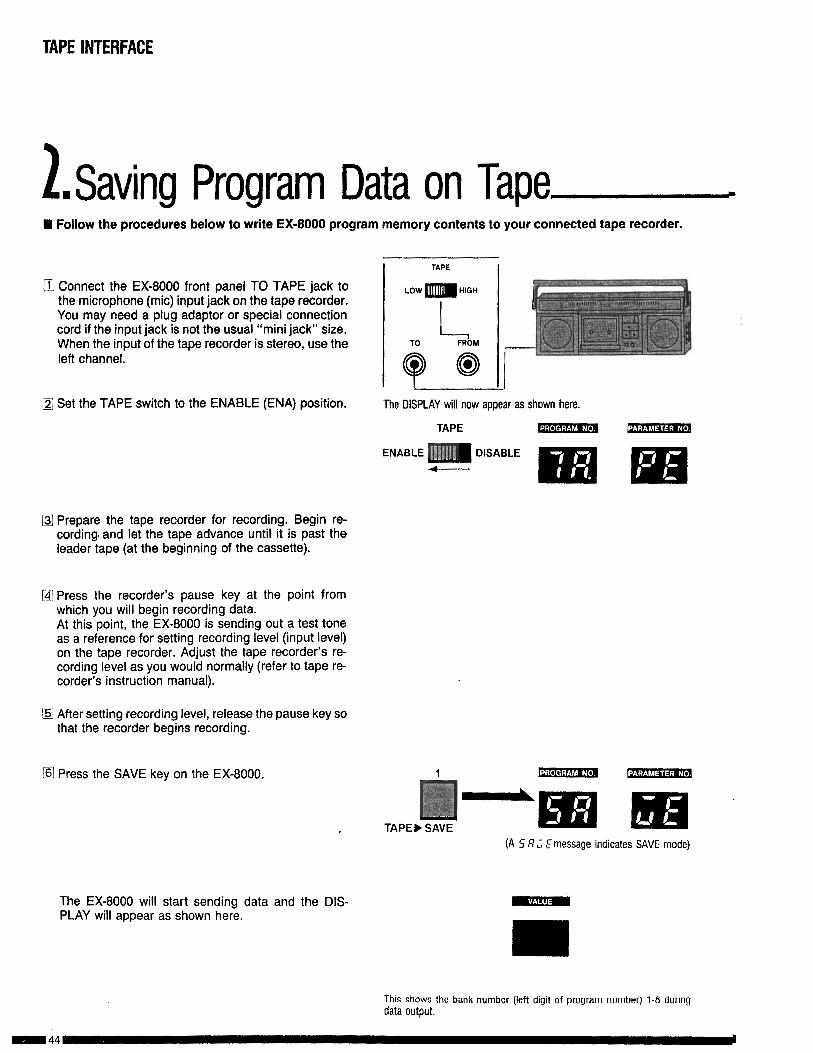
1Saving Program Data on Tape.W Follow the procedures below to write EX-8000 program memory contents to your connected tape recorder.
q Connect the EX-8000 front panel TO TAPE jack tothe microphone (mic) input jack on the tape recorder.You may need a plug adaptor or special connectioncord if the input jack is not the usual “mini jack” size.When the input of the tape recorder is stereo, use theleft channel.
/ZJ Set the TAPE switch to the ENABLE (ENA) position.
I TAPE I
The DISPLAY will now appear as shown here.
TAPE
ENABLE m DISABLE
m
q Prepare the tape recorder for recording. Begin re-cording. and let the tape advance until it is past theleader tape (at the beginning of the cassette).
@I Press the recorder’s pause key at the point fromwhich you will begin recording data.At this point, the EX-8000 is sending out a test toneas a reference for setting recording level (input level)on the tape recorder. Adjust the tape recorder’s re-cording level as you would normally (refer to tape re-corder’s instruction manual).
q After setting recording level, release the pause key sothat the recorder begins recording.
q Press the SAVE key on the EX-8000.
TAPE b SAVE(A 5 8; E message indicates SAVE mode)
The EX-8000 will start sending data and the DIS-PLAY will appear as shown here.
This shows the bank number (left digit of program number) 1-8 dungdata output.

TAPE INTERFACE
q When the DISPLAY again shows TAPE, then you canstop the tape recorder.This completes the SAVE procedure. However, it isgood practice to repeat the SAVE procedure severaltimes, as a hedge against the possibility of losingdata because of tape dropouts.
B Reset the EX-8000 front panel TAPE switch to theDISABLE position.
a Do not change any settings on the EX-8000 until youcomplete the VERIFY procedure (in the followingsection).
TAPE
ENABLE DISABLE
e
n If you listen to a tape of recorded data, you willhear the following tones:
-.I. * . . , -a -._ Leader tone: Indicates the start of VERIFY and LOADoperations.
Data tone: The actual digital data from EX-8000 soundprogram memory.
End tone: Indicates the end of the operation.

TAPE INTERFACE
3n VERlFY Proceduren The VERIFY procedure should always be used immediately after you finish a SAVE (or LOAD) operation. This
is to make sure that data has been properly recorded. It is also useful for determining the best playback levelsetting for your recorder.
q Connect the EX-8000 front panel FROM TAPE jack tothe output jack (earphone, line out, etc.) of yourrecorder. Set the High/Low switch to match your taperecorder’s output signal level.
B Set the EX-8000 panel TAPE switch to the ENABLEposition.
l3l Set the tape recorder’s playback volume a bit higherthan usual. If the recorder has tone controls, set themto the center positions.
q Rewind the tape. Begin tape playback. Stop the tape(using the stop or pause key) when you reach the be-ginning of the leader tone.
q Press the VERIFY key on the EX-8000.The DISPLAY will show “VERIFY” to confirm theVERIFY mode.
q Start the tape recorder (press the play key or releasethe pause key). The DISPLAY will show “VERIFY” toconfirm the VERIFY mode.
TAPE
LOW m HIGH
TO FROM
Recorder output lack HIGH/LOW
- From recorder
This shows the EX-8000 is in the tape interface mode.
TAPE
VERIFY
The DISPLAY will
L show the banknumber (l-8) forthe VERIFY opera-tion.
TAPE INTERFACE
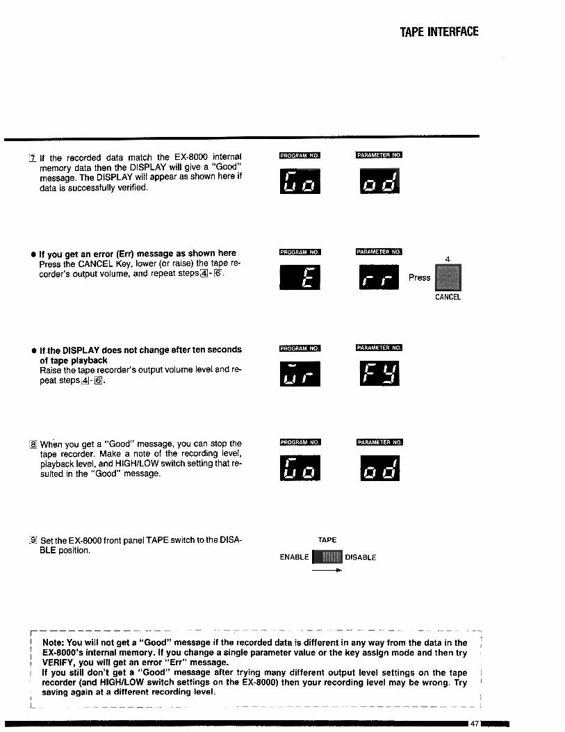
q If the recorded data match the EX-8000 internalmemory data then the DISPLAY will give a “Good”message. The DISPLAY will appear as shown here ifdata is successfully verified.
0 If you get an error (Err) message as shown herePress the CANCEL Key, lower (or raise) the tape re-corder’s output volume, and repeat steps&$l- lj$J
CANCEL
0 If the DISPLAY does not change after ten secondsof tape playbackRaise the tape recorder’s output volume level and re-peat steps m- @I.
q When you get a “Good” message, you can stop the mtape recorder. Make a note of the recording level,playback level, and HIGH/LOW switch setting that re-sulted in the “Good” message.
•I Set the EX-8000 front panel TAPE switch to the DISA-BLE position.
TAPE
ENABLE DISABLE
w
r ______ -__------ ------ --------------------------,
1 Note: You will not get a “Good” message if the recorded data is different in any way from the data in the /, EX-8000’s internal memory. If you change a single parameter value or the key assign mode and then try 11 VERIFY, you will get an error “Err” message. I( If you still don’t get a “Good” message after trying many different output level settings on the tape I) recorder (and HIGH/LOW switch settings on the EX-8000) then your recording level may be wrong. Try
saving again at a different recording level.1
IL ________ ------ -..--- ~~-----.-- ----- - ---- -----------_I

TAPE INTERFACE
4. LOAD ProcedurecH This procedure is used to put recorded data back into the EX-8000’s internal memory.
q Connect the EX-8000 front panel FROM TAPE jack tothe output jack (earphone, line out, etc.) of your re-corder. Set the HlGHlLOWswitch to match your taperecorder’s output signal level.
q Set the EX-8000 front panel WRITE switch and TAPEswitch to the ENABLE (ENA) positions.
TAPEENABLE m DISABLE-
The DISPLAY will now appear as shown here.m m
q Set the tape recorder’s playback volume to the levelthat produced a “Good” message when you use theVERIFY procedure. If the recorder has tone controls,set them to the center positions.
i!$ Rewind the tape. Begin tape playback. Stop the tape(using the stop or pause key) when you reach the be-ginning of the leader tone.
0 Press the LOAD key.
@ Start tape playback (press the play key or release thepause key). The Display will appear as shown here.
LOAD
This shows thebank number (1- 8) if data isloading.
TAPE INTERFACE
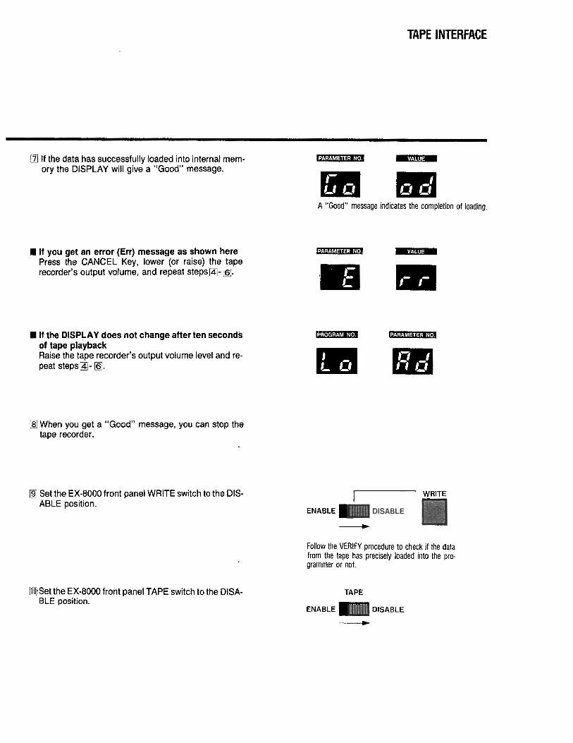
q If the data has successfully loaded into internal mem-ory the DISPLAY will give a “Good” message.
I If you get an error (Err) message as shown herePress the CANCEL Key, lower (or raise) the taperecorder’s output volume, and repeat steps@- q .
n If the DISPLAY does not change after ten second&of tape playbackRaise the tape recorder’s output volume level and re-peat steps@- q J.
181 When you get a “Good” message, you can stop thetape recorder.
@ Set the EX-8000 front panel WRITE switch to the DIS-ABLE position.
@Set the EX-8000 front panel TAPE switch to the DISA-BLE position.
m mA “Good” message indicates the completion of loading.
m m
ENABLE
Follow the VERIFY procedure to check if the datafrom the tape has precisely loaded into the pro-grammer or not.
TAPE
TAPE INTERFACE
s.Tape Interface Precautions
1
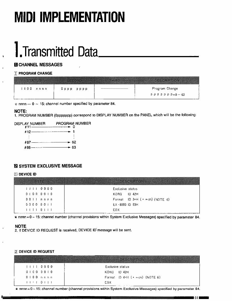
, 1 ‘Transmitted Dataq CHANNEL MESSAGES* I
q PROGRAMCHANGE
,
1100 n n n n O P P P P P P P P r o g r a m C h a n g e
P P P P P P P=O-63
* nnnn - 0 - 15: channel number specified by parameter 84.
NOTE:1. PROGRAM NUMBER (Oppppppp) correspond to DISPLAY NUMBER on the PANEL which will be the following:
DISPL$;,NUMBER PROGRAY NUMBER.
#12 ,l
#87 * 62#88 e 63
q SYSTEM EXCLUSIVE MESSAGE
q DEVICE ID
IIII 0 0 0 0 E x c l u s i v e s t a t u s
0100 0 0 1 0 K O R G ID 42l-l
0011 n n n n F o r m a t ID 3*H ( * =ch) ( N O T E 6 )
0 0 0 0 001 I EX -8000 ID 03H
IIll OIlI E O X
* nnnn = 0 - 15: channel number (channel provisions within System Exclusive Messages) specified by parameter 84.
NOTE2. If DEVICE ID REQUEST is received, DEVICE ID message will be sent.
q DEVICE ID REQUEST
Illi 0 0 0 0 Excluswe stat us
0100 0010 K O R G I D 4 2 H
0 1 0 0 n n n n F o r m a t I D 4*H (* =ch) (NOTE 6)
III1 OIlI E O X
* nnnn = 0 - 15: channel number (channel provisions within System Exclusive Messages) specified by parameter 84.
I 51-

3 DATA DUMP
III1 0 0 0 0
0 1 0 0 0 0 1 0
0 0 1 I n n n n
0 0 0 0 0 0 1 I
0 1 0 0 0 0 0 0
o v u v v v v u
o v v v v v v vIllI 0111
E x c l u s i v e s t a t u s
K O R G ID 42H
F o r m a t I D 3*H (* =ch) (NOTE 6 )
EX -8000 ID 03H
D a t a D u m p 4 0 H
D a t a 51 B y t e s
( S e e E X -.8000 B I T M A P )
E O X
* nnnn = 0 - 15: channel number (channel provisions within System Exclusive Messages) specified by parameter 84.
NOTE3. If DATA DUMP REQUEST is received, DATA DUMP will be sent.
/-4J DATA DUMP REQUEST
III1 0 0 0 0
0 1 0 0 0010
001 I n n n n
0 0 0 0 001 I
0 0 0 1 0 0 0 0
IIII 0111
Exclus ive s ta tus
K O R G I D 42H
F o r m a t I D 3*H ( * =ch) ( N O T E 6 )
EX -8000 ID 03H
D a t a Save R e q u e s t IOH
E O XI-
* nnnn = 0 - 15:channel number (channel provisions within System Exclusive Messages) specified by parameter 84.
q WRITE COMPLETED
IIll 0 0 0 0 E x c l u s i v e s t a t u s
0 1 0 0 0 0 1 0 K O R G ID 42H
0 0 1 I n n n n F o r m a t I D 3*~ ( * =ch) (NOTE 6)
0 0 1 0 001 I EX -8000 ID 03H
0 0 0 0 0 0 0 1 Write C o m p l e t e d 2lH
IllI 0111 E O X
* nnnn = 0 - 15: channel number (channel provisions within System Exclusive Messages) specified by parameter 34.
NOTE4. If WRITE REQUEST is received and program write is completed, a WRITE COMPLETED message will be sent.
MIDI IMPLEMENTATION
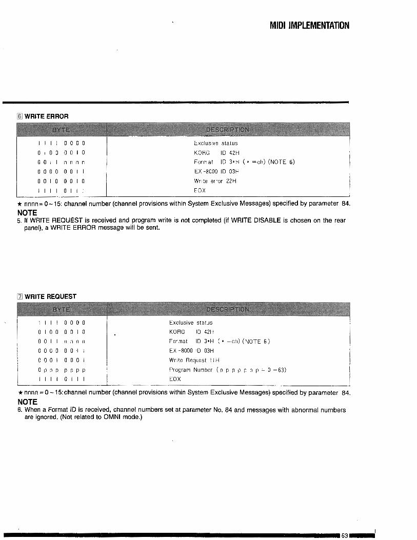
a WRITE ERROR
III1 0 0 0 0
0 1 0 0 0 0 1 0
0011 n n n n
0 0 0 0 001 I
0 0 1 0 0 0 1 0
IIII 0111
Excluslue s t a t u s
KORG ID 42H
F o r m a t I D 3*H (* =ch) ( N O T E 6 )
E X - 6 0 0 0 I D 0 3 H
Write e r r o r 2 2 H
E O X
* nnnn= O-15: channel number (channel provisions within System Exclusive Messages) specified by parameter 84.NOTE5. If WRITE REQUEST is received and program write is not completed (if WRITE DISABLE is chosen on the rear
panel), a WRITE ERROR message will be sent.
[51 WRITE REQUEST
III1 0 0 0 0
0 1 0 0 0 0 1 0
0011 n n n n
0 0 0 0 00-I I
0 0 0 1 0 0 0 1
O P P P P P P P
III1 OIlI
Excluswe s t a t u s
K O R G ID 42H
F o r m a t I D 3*H (* =ch) ( N O T E 6 )
EX -8000 ID 03H
Write Request I IH
Program Number ( p p p p p p p = 0 -63)
E O X
+ nnnn = 0 - 15: channel number (channel provisions within System Exclusive Messages) specified by parameter 84.
NOTE6. When a Format ID is received, channel numbers set at parameter No. 84 and messages with abnormal numbers
are ignored. (Not related to OMNI mode.)
MIDI IMPLEMENTATION
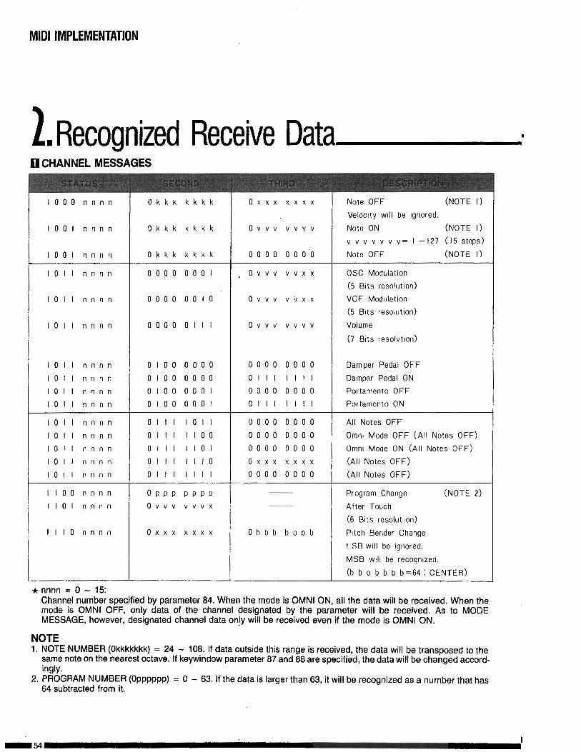
1RI ecognized Receive Data I0 CHANNEL MESSAGES
1 0 0 0 n n n n
1 0 0 1 n n n n
1 0 0 1 n n n n
O k k k k k k k o x x x x x x x
O k k k k k k k
O k k k k k k k
N o t e O F F (NOTE I)
Velocrty WIII b e I g n o r e d .
o v v v v v v v N o t e O N ( N O T E I)
v v v v v v v= I -127 (I5 steps)
0 0 0 0 0 0 0 ’ 0 N o t e O F F ( N O T E I)
1011 n n n n 0 0 0 0 0 0 0 1 . o v v v v v x x 0% Modulatton
( 5 Btts resolutron)
1011 n n n n 0 0 0 0 0 0 1 0 o v v v v v x x V C F M o d u l a t i o n
( 5 Bits resolutron)
1011 n n n n 0000 01 I I o v v v v v v v Volume
( 7 Brts resolvtron)
1011 n n n n 0 1 0 0 0 0 0 0 0 0 0 0 0 0 0 0 D a m p e r P e d a l O F F
1011 n n n n 0100 0 0 0 0 0111 III1 D a m p e r P e d a l O N
1011 n n n n 0 1 0 0 0 0 0 1 0 0 0 0 0 0 0 0 P o r t a m e n t o O F F
loll n n n n 0 1 0 0 0 0 0 1 OIlI Iill P o r t a m e n t o O N
I011 n n n n OIlI 1011 0 0 0 0 0 0 0 0 A l l N o t e s O F F
1011 n n n n 0111 1100 0 0 0 0 0 0 0 0 Omm M o d e O F F ( A l l N o t e s O F F )
1011 n n n n OIlI II01 0 0 0 0 0 0 0 0 Omnr M o d e O N ( A l l N o t e s O F F )
1011 n n n n 0111 Ill0 o x x x x x x x ( A l l N o t e s O F F )
1011 n n n n OIlI III1 0 0 0 0 0 0 0 0 ( A l l N o t e s O F F )
1 1 0 0 n n n n O P P P P P P P P r o g r a m C h a n g e ( N O T E 2)
I101 n n n n o v v v v v v x A f t e r T o u c h
( 6 Bits r e s o l u t Ion)
I I I O n n n n o x x x x x x x O b b b b b b b P i t c h B e n d e r C h a n g e
L S B will b e I g n o r e d .
M S B WIII b e r e c o g n i z e d .
(b b b b b b b=64 : C E N T E R )
* nnnn = 0 - 15:Channel number specified by parameter 84. When the mode is OMNI ON, all the data will be received. When themode is OMNI OFF, only data of the channel designated by the parameter will be received. As to MODEMESSAGE, however, designated channel data on!y will be received even if the mode is OMNI ON.
NOTE1. NOTE NUMBER (Okkkkkkk) = 24 - 108. If data outside this range is received, the data will be transposed to the
same note on the nearest octave. If keywindow parameter 87 and 88 are specified, the data will be changed accord-ingly.
2. PROGRAM NUMBER (Opppppp) = 0 - 63. If the data is larger than 63, it will be recognized as a number that has64 subtracted from it.
-54I

MIDI IMPLEMENTATION
q SYSTEM EXCLUSIVE MESSAGES
q DEVICE ID
q DEVICE ID REQUEST
K?j DATA DUMP
@ DATA DUMP REQUEST
q WRITE COMPLETED
q WRITE ERROR
q WRITE REQUEST‘\
The above system exclusive messages are the same as Transmitted Data. Refer to page 51.
[81 PARAMETER CHANGE
III/ 0 0 0 0
0 1 0 0 0 0 1 0
001 I n n n n
0 0 0 0 001 I
0 1 0 0 0 0 0 1
o v v v v v v v
o v v v v v v v
IIII OIlI
Exclusive s t a t u s
K O R G ID 42H
F o r m a t I D 3*H ( 8 =ch) (NOTE 3 )
EX -8000 ID 03H
Paramet,er C h a n g e 4 1 H
P a r a m e t e r O f f s e t ( S e e E X - 8 0 0 0 B I T M A P )
P a r a m e t e r V a l u e ( S e e E X - 8 0 0 0 B I T M A P )
E O X
* nnnn = 0 - 15: channel .number (channel provisions within System Exclusive Messages) specified by parameter 84.NOTE3. Messages with channel numbers different from those specified by parameter 84 are ignored.
(This has no relation to OMNI mode setting.)
q SYSTEM REAL TIME MESSAGE
A C T I V E SENSING(440ms)

Jommunication BetweenEX-8000 and Other Equipment c
El ‘EX-8000 Transmits/Receives information in the form of the following System ExclusiveMessages.
Transmitted/Received Messages
DEVICE ID : Data regarding type of equipment being used. Transmits this data when a DEVICE ID isreceived.
DEVICE ID REQUEST : Requests data on what type of equipment EX-8000 is communicating with.DATA DUMP : Information on sound data. Transmits this data when a DATA DUMP REQUEST is
received.DATA DUMP REQUEST : Information requesting sound data.WRITE COMPLETED : Verifies that Program Write has been performed correctly. Responds to WRITE RE-
QUEST.WRITE ERROR : Informs that WRITE switch is set to DISABLE and Program Write cannot be performed.
Responds to WRITE REQUEST.WRITE REQUEST : Information used to write received data in EX-8000 programmer.
Received OnlyPARAMETER CHANGE : Information used to change value of sound parameters.
n By using these System Exclusive Messages, the EX-8000 can communicate with other MIDI capable equipmentsuch as the DW-8000, and computers. (Proper software is necessary in the case of computer communication.)
H Sound Data TransferMIDI Data Transfer allows sound data to be passed be-tween multiple EX-8000’s, DW-8000’s, etc. via systemexclusive messages. In addition, particular sounds canbe transferred to open Program numbers. To accom-plish this, MIDI channels of relative equipment must bethe same as the EX-8000’s.
As shown above, connect the EX-8000’s MIDI OUT to MIDI IN of otherMIDI equipment and EX-8000 MIDI IN to other equipment’s MIDI OUT.
MIDI Data Transfer-Related Parameters
MIDI DATA TRANSFERThis parameter controls data transfer modes. (notshown on panel)
VALUE- -
2
Single Program Load(Receives one sound only)
All Program Load(Receives all 64 sounds)
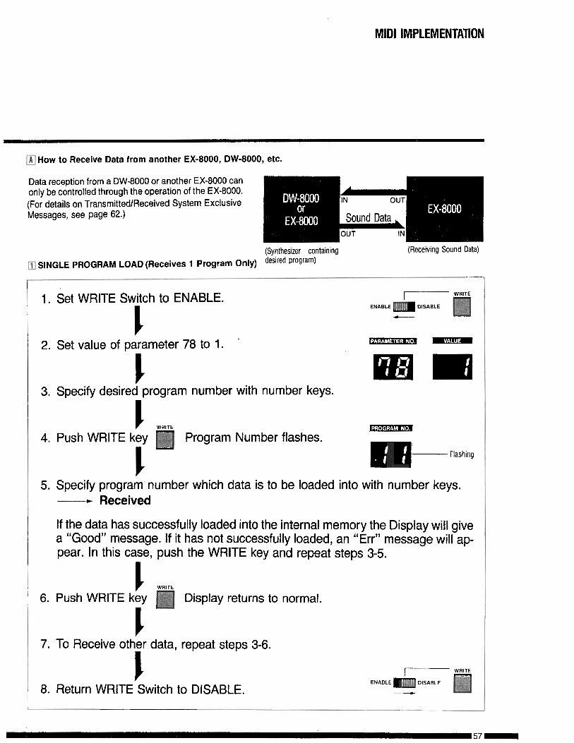
q How to Receive Data from another EX-8000, DW-8000, etc.
(Synthesizer containing (Receiving Sound Data)
m SINGLE PROGRAM LOAD (Receives 1 Program Only) desired program)
1. Set WRITE Switch to ENABLE.c2. Set value of parameter 78 to 1. ’
WRlTFI _
ENABLE m DISABLE
3. Specify desired program number with number keys.
I WRlTE4. Push WRITE key q Program Number flashes.
cFlashing
5. Specify program number which data is to be loaded into with number keys.------+ R e c e i v e d
If the data has successfully loaded into the internal memory the Display will givea “Good” message. If it has not successfully loaded, an “Err” message will ap-pear. In this case, push the WRITE key and repeat steps 3-5.
c WRITE6. Push WRITE key q Display returns to normal.
I7. To Receive other data, repeat steps 3-6.
I8. Return WRITE Switch to DISABLE. -
MlDi IMPLEMENTATION
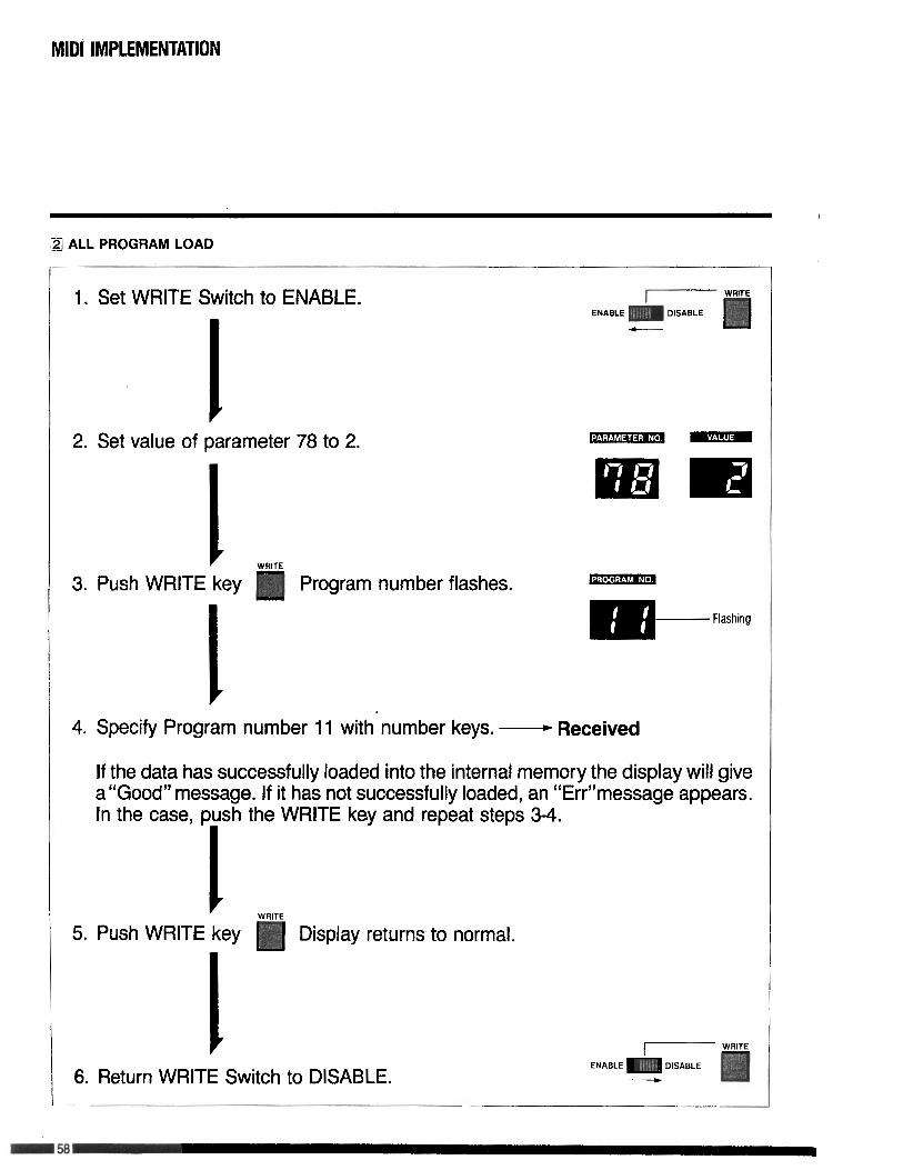
q ALL PROGRAM LOAD
1. Set WRITE Switch to ENABLE.
I2. Set value of parameter 78 to 2.
I3. Push WRITE key Program number flashes.
I
Flashing
4. Specify Program number 11 with number keys,- Received
If the data has successfully loaded into the internal memory the display will givea “Good” message. If it has not successfully loaded, an “Err”message appears.In the case, push the WRITE key and repeat steps 3-4.
1 WRITE5. Push WRITE key Display returns to normal.
I I------- WRITE
6. Return WRITE Switch to DISABLE.ENABLE m DISABLE
__c
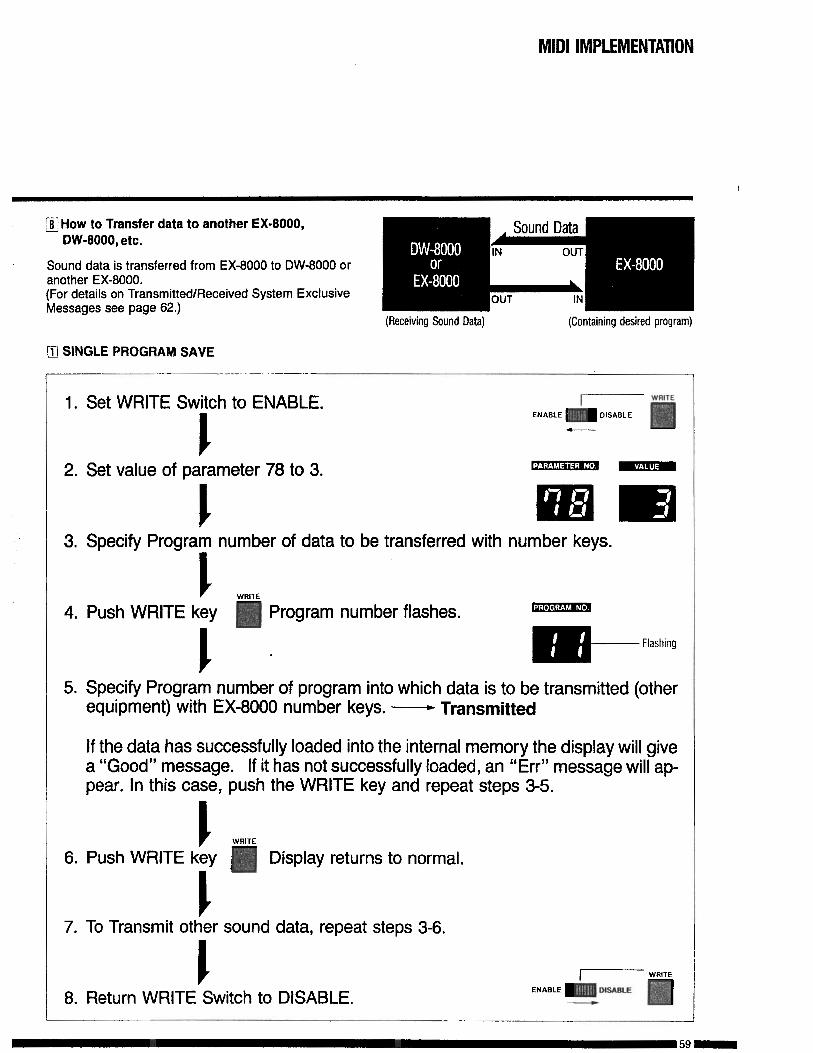
q How to Transfer data to another EX-8000,DW-8000, etc.
Sound data is transferred from EX-8000 to DW-8000 oranother EX-8000.(For details on Transmitted/Received System ExclusiveMessages see page 62.)
(Receiving Sound Data) (Containing desired program)
m SINGLE PROGRAM SAVE
1. Set WRITE Switch to ENABLE.
I2. Set value of parameter 78 to 3.
3. Specify Program number of data to be transferred with number keys.
I WRITE4. Push WRITE key Program number flashes.
IFlashing
5. Specify Program number of program into which data is to be transmitted (otherequipment) with EX-8000 number keys. - Transmitted
If the data has successfully loaded into the internal memory the display will givea “Good” message. If it has not successfully loaded, an “Err” message will ap-pear. In this case, push the WRITE key and repeat steps 3-5.
I WRITE6. Push WRITE key Display returns to normal.
I7. To Transmit other sound data, repeat steps 3-6.
8. Return WRITE Switch to DISABLE.
59-
MIDI IMPLEMENTATION
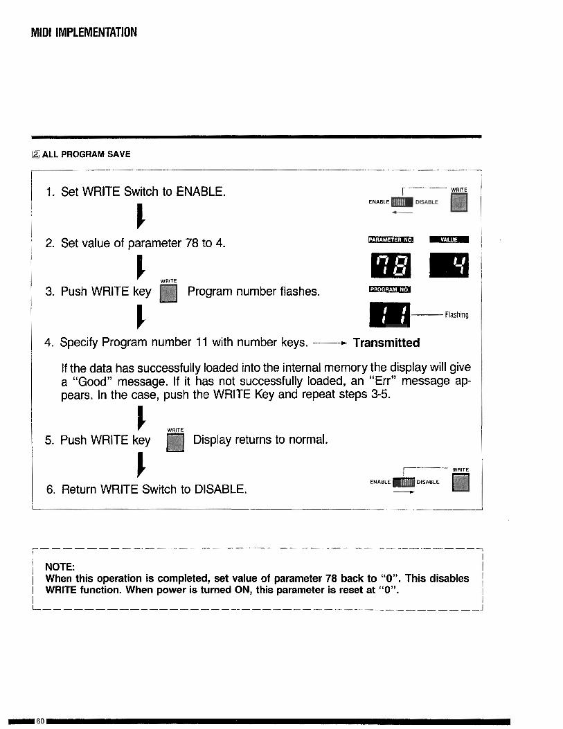
!Z’ ALL PROGRAM SAVE
1. Set WRITE Switch to ENABLE.
2. Set value of parameter 78 to 4.
WRITE3. Push WRITE key q Program number flashes. m
m-Flashing
4. Specify Program number 11 with number keys, --- Transmitted
If the data has successfully loaded into the internal memory the display will givea “Good” message. If it has not successfully loaded, an “Err” message ap-pears. In the case, push the WRITE Key and repeat steps 3-5.
WRITE5. Push WRITE key Display returns to normal.
f6. Return WRITE Switch to DISABLE.
r---- ____ --------- ---- ------------------1\ NOTE: ;1 When this operation is completed, set value of parameter 78 back to “0”. This disables1 WRITE function. When power is turned ON, this parameter is reset at “0”.
1I
L-------------------------- - - - - -----_- _ _ _ _ _ _ _ _ J
MIDI IMPLEMENTATION
. Examples of System ExclusiveMessages Used in Communicatingwith Other Equipment ,
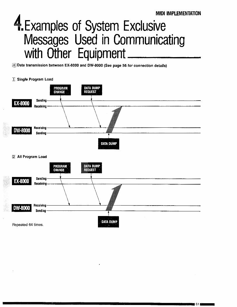
@ Data transmission between EX-8000 and DW-8000 (See page 56 for connection details)
q Single Program Load
Sending
Receiving
Receiving
Sending
H All Program Load
Repeated 64 times.
61-
MIDI IMPLEMENTATION
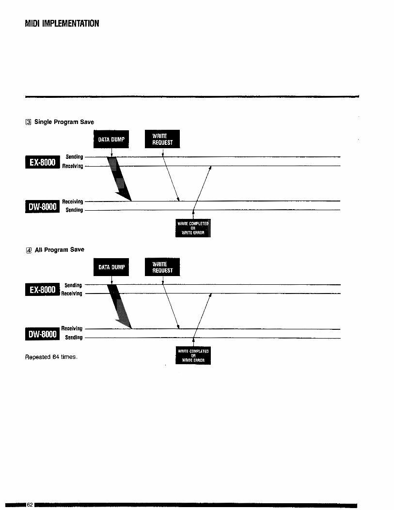
q Single Program Save
(&I All Program Save
Repeated 64 times.
MIDI IMPLEMENTATlON
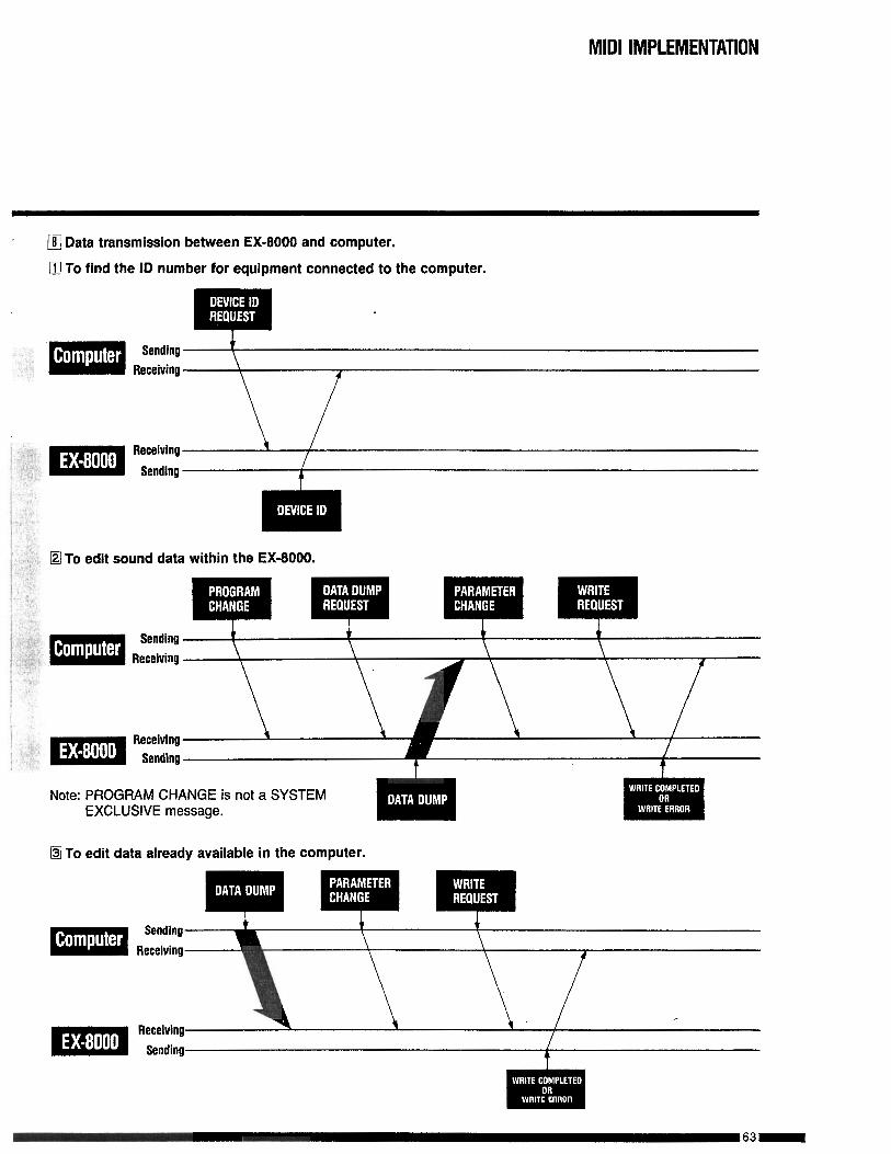
m Data transmission between EX-8000 and computer.
0 To find the ID number for equipment connected to the computer.
Sending t
Receiving
Iq To edit sound data within the EX-8000.
Note: PROGRAM CHANGE is not a SYSTEMEXCLUSIVE message.
@ To edit data already available in the computer.
Sending
Receiving

MIDI IMPLEMENTATION
M To load all 64 sound programs from the computer to the EX-8000.
SendingReceiving
Receiving
Sending
Repeated 64 times.
m To save all 64 sound programs from the EX-8000 to the computer.
Sending
Receiving
Repeated 64 times.

MIDI IMPLEMENTATION
5HEX-8000 BIT MAPq EX-8000 BIT MAP
0 0 0 0 0 0 0 OSC I OCTAVE
I 0 0 0 0 O S C I W A V E F O R M
2 0 0 0 O S C I L E V E L
A U T O B E N D3 0 0 0 0 0 0
S E L E C T
A B E N D4 0 0 0 0 0 0 0
M O D E
5 0 0
6 0 0
1 0 0
a 0 0
9 0 0
IO 0 0
I I 0 0
12 0 0
13 0 0
14 0 0
15 0 0
16 0 0
17 0 0
18 0 0
0
0
0
0
0
0
0
0
0
0
0
0
A. B E N D T I M E
A . B E N D I N T E N S I T Y
0 0 0 OSC 2 OCTAVE
0 O S C 2 W A V E F O R M
O S C 2 L E V E L
0 0 INTERVAL
0 0 DETUNE
N O I S E L E V E L
0 0 0 ASSIGN MODE
P A R A M E T E R N O . M E M O R Y
C U T O F F
R E S O N A N C E
0 0 0 KBD. TRACK
0 0 0 0P O L A -
R I T Y
19 0 0 0 E G . I N T E N S I T Y
20 0 0 0 V C F A T T A C K
21 0 0 0 V C F D E C A Y
22 0 0 0 V C F B R E A K P .
23 0 0 0 V C F S L O P E
24 0 0 0 VCF SUSTAIN

MIDI IMPLEMENTATION
2 5 0 0
26 0 0
27 0 0
28 0 0
29 0 0
30 0 0
31 0 0
32 0 0
33 0 0
34 0 0
35 0 0
36 0 0
3 1 0 0
38 0 0
38 0 0
40 0 0
0 V C F R E L E A S E
0 0 0 V C F V E L O C I T Y S E N S
0 V C A A T T A C K
0 V C A D E C A Y
0 V C A B R E A K P
0 V C A S L O P E
0 V C A S U S T A I N
0 V C A R E L E A S E
0 0 0 V C A V E L O C I T Y S E N S
0 0 0 0 MG WAVE FORM
0 M G F R E Q U E N C Y
0 M G D E L A Y
0 M C O S C
0 M G V C F
0 0 B E N D O S C
.
0 0 0 0 0B E N D
V C F
46 0 0 0 0 D E L A Y E F F E C T L E V E L
4 1 0 0 0 P O R T A M E N T O
48 0 0 0 0 0 0 AFTER J.OSC MG
49 0 0 0 0 0 0 AFTER T VCF
50 0 0 0 0 0 0 AFTER T VCA

MIDI IMPLEMENTATION
Q EX-8000 BIT MAP AND CORRESPONDING PARAMETER VALUES
-O S C I Cctave 0 bl - b O OO= 16 01=8 IO=4 I I =INHIBIT II
OSC I Wave Form I b3-b0 OOOO-IIIl=I-I6 I2
O S C I L e v e l 2 b4-b0 ooooo-IIIIl=O-31 I3
A. B. Select ( 3 ( bl-b0 I ~~=OFF 0 1 =OSCI 1o=osc2 II=BOTH 1 14
A. B. Mode I 4 I b0 O=UP I =DOWN I 15
A. 9. Time I 5 I b4-b0 ooooo-IIIII=O-31 I I6
A. B. ht. I 6 I b4-b0 ooooo-IIIII=O-31 I I7
OSC 2 Octave I 7 I b l -bO OO=l6 Ol=8 IO=4 II=INHIBIT 1 21
O S C 2 Wave F o r m 8 b3-b0 OOOO-IIII=i-I6 22
O S C 2 Level 9 b4-b0 ooooo-11111=0-31 23
o s c 2In terva l
IO b2-b0OOO=l ooi=-3 OlO=3 Oll=4 loo=5IO1 - I I I =INHIBIT
24
O S C 2 Detune
N o i s e L e v e l
C u t o f f
,II b2-b0 OOO-IIO=O-6 III=INHIBIT 25
I2 b4-b0 ooooo- I I I I I =o-31 26
I5 b5-b0 OOOOOO-IIIIII=O-63 31
Resonance
KBO T r a c k
I6
17
b4-b0 ooooo-IIIII=O-31 32
bl-b000=(O) Ol=l(l/4) 10=2(1/2)I I = 3 ( l )
33
Polar i ty I I8 I b0 O=l(h) 1=2&J) I 34
V C F E G I n t . I 19 I b4-b0 ooooo-IIIII=O-31 I 35
V C F A t t a c k
V C F D e c a y
20 b4-b0 ooooo-I1III=0-31 41
21 b4-b0 ’ ooooo-IIIII=O-31 42
V C F B r e a k P .
V C F S l o p e
22 b4-b0
23 b4-b0
ooooo-IIIII=O-31 43
ooooo-IIIII=O-31 44
V C F S u s t a i n 24
8b4-b0 ooooo-IIIII=O-31 4 5
V C F R e l e a s e I 25 I b4-b0 ooooo-11111=0-31 I 4 6
VCF V. Sens I 26 I b2-b0 1 ooo- I I I =o-7 I 47
V C A A t t a c k 27 b4-b0 ooooo-IIIII=O-31 51
MIDI IMPLEMENTATION
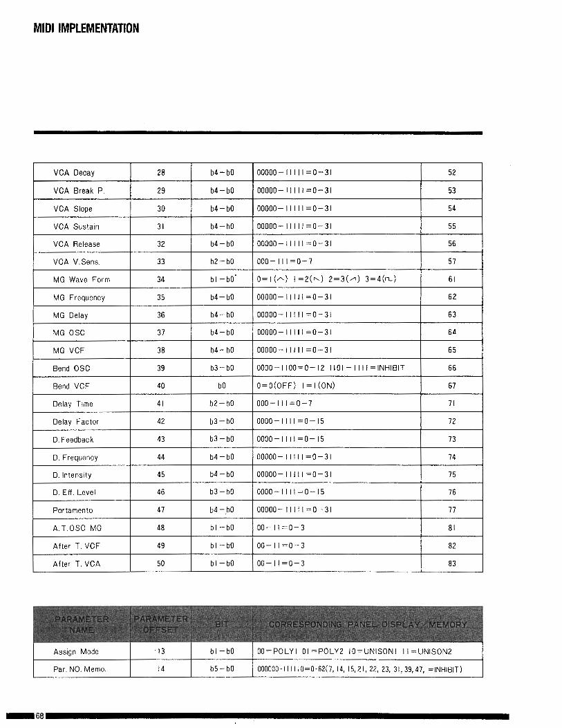
V C A D e c a y 28
V C A B r e a k P . 29
V C A S l o p e 30
V C A S u s t a m 31
V C A R e l e a s e 32
V C A V.Sens 33
M G W a v e F o r m 34
M G F r e q u e n c y 35
M G D e l a y 36
M G O S C 37
M G V C F 38
B e n d O S C 39
B e n d V C F 40
D e l a y Time 41
D e l a y F a c t o r 42
D. Feedback 43
D. Frequency 44
D. lntenslty 45
D. Eff. Level 46
P o r t a m e n t o 47
A.T.OSC M G 48
A f t e r T . V C F 49
A f t e r T . V C A 50
b4-b0
b4-b0
b4-b0
b4-b0
b4-b0
b2-b0
bl -bO’
b4-b0
b4-b0
b4-b0
b4-b0
b3-b0
b0
b2-b0
b3-b0
b3-b0
b4-b0
b4-b0
b3-b0
b4 -,bO
bl -bO
bl -bO
bl-bO
ooooo-IIII1=0-31 52
ooooo- I I I I I =o-31 53
ooooo-IIIII=O-31 54
ooooo-IIIII=O-31 55
ooooo-IIIII=O-31 56
ooo-III=O-7 57
O= I(A) I =2(h) 2=3(/l 3=4(m) 61
ooooo-IIIII=O-31 6 2
ooooo-11111=0-31 6 3
ooooo-11111=0-31 6 4
ooooo-11111=0-31 6 5
OOOO-llOO=O-I2 IIOI-llII=INHIBIT 6 6
O=O(OFF) I = I (ON) 67
ooo-III=O-7 71
oooo-IIII=O-I5 72
oooo-IIIl=O-I5 73
ooooo-1II11=0-31 74
ooooo-IIIII=O-31 75
oooo-IIII=O-I5 76
ooooo-IIIII=O-31 77
oo-ll=O-3 81
oo-ll=O-3 82
oo-ll=O-3 8 3
I-- A s s i g n M o d e I3 I b l -bO OO=POLYl 01 =P0LY2 IO=UNISONI I I =UNISON2
)o. 1 14 1 b5-bO 1 000000-1 I I I lO=O-62(7, 14, 15,21, 22, 23, 31,39,47, =lNHIBIT)l
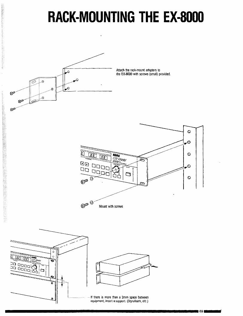
RACK-MOUNTING THE EX-8000
Attach the rack-mount adapters tothe EX-8000 with screws (small) provided.
Mount with screws
If there is more than a 3mm space betweenequipment, insert a support. (Styrofoam, etc.)
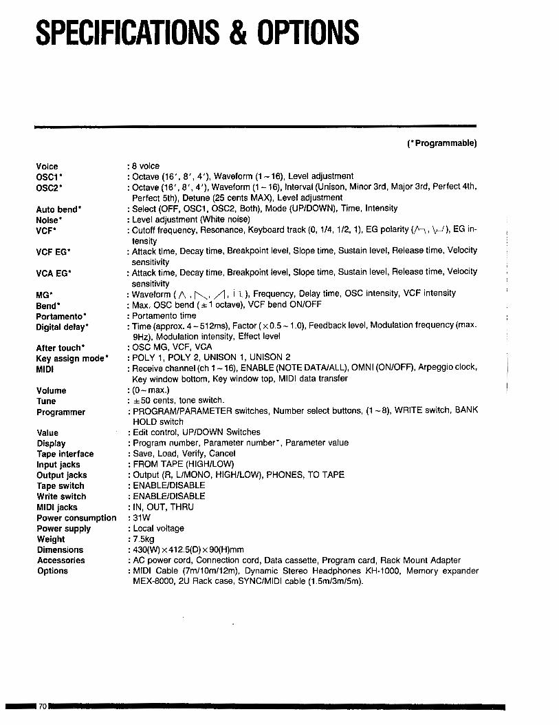
SPECIFICATIONS & OPTIONS
VoiceOSCl losc2 l
Auto bend*Noise*VCY
VCF EG’
VCA EG*
MG*Bend*Portamento’Digital delay*
After touch*Key assign mode’MIDI
VolumeTuneProgrammer
ValueDisplayTape interfaceInput jacksOutput jacksTape switchWrite switchMIDI jacksPower consumptionPower supplyWeightDimensionsAccessoriesOptions
( l Programmable)
: 8 voice: Octave (16’, 8’, 40, Waveform (1 - 16), Level adjustment: Octave (16’, 8’, 4’), Waveform (1 - 16), Interval (Unison, Minor 3rd, Major 3rd, Perfect 4th,Perfect 5th), Detune (25 cents MAX), Level adjustment
: Select (OFF, OSCl, OSC2, Both), Mode (UP/DOWN), Time, intensity: Level adjustment (White noise): Cutoff frequency, Resonance, Keyboard track (0, l/4, l/2, l), EG polarity (k, \/-/), EG in-
tensity: Attack time, Decay time, Breakpoint level, Slope time, Sustain level, Release time, Velocitysensitivity
: Attack time, Decay time, Breakpoint level, Slope time, Sustain level, Release time, Velocitysensitivity
: Waveform ( A , [\, /) , i-L ), Frequency, Delay time, OSC intensity, VCF intensity: Max; OSC bend ( f 1 octave), VCF bend ON/OFF: Portamento time: Time (approx. 4 -512ms), Factor ( x 0.5 - 1 .O), Feedback level, Modulation frequency (max.
9Hz), Modulation intensity, Effect level: OSC MG, VCF, VCA: POLY 1, POLY 2, UNISON 1, UNISON 2: Receive channel (ch 1 - 16), ENABLE (NOTE DATAIALL), OMNI (ON/OFF), Arpeggio clock,
Key window bottom, Key window top, MIDI data transfer: (0 - max.): *50 cents, tone switch.: PROGRAM/PARAMETER switches, Number select buttons, (1 -8), WRITE switch, BANK
HOLD switch: Edit control, UP/DOWN Switches: Program number, Parameter number*, Parameter value: Save, Load, Verify, Cancel: FROM TAPE (HIGH/LOW): Output (R, L/MONO, HIGH/LOW), PHONES, TO TAPE: ENABLE/DISABLE: ENABLE/DISABLE: IN, OUT, THRU: 3lW: Local voltage: 7.5kg: 430(W) x 4125(D) x SO(H)mm: AC power cord, Connection cord, Data cassette, Program card, Rack Mount Adapter: MIDI Cable (7m110m/l2m), Dynamic Stereo Headphones KH-1000, Memory expander
MEX-8000, 2U Rack case, SYNC/MIDI cable (lB5m/3m/5m).

!II1.
1
ill..
,.
-..
.” ,.
.,
:
.”
N 0 1 I C EKorg products are manufactured under strict specifications and voltagesrequired by each country. These products are warranted by the Korg distri.butor only in each counlry. Any Korg product not sold with a warranty cardor carrying a serial number disqualifies the product sold from the manufac-turer’sldistributor’s warranty and liability. This requirement is for your ownorotection and safety.
I 71 -