programmable control products pacsystems* rx3i ge intelligent platforms programmable control...
TRANSCRIPT

GE Intelligent Platforms
Programmable Control Products
PACSystems* RX3i Serial Communications Modules User’s Manual, GFK-2460E June 2010

GFL-002
Warnings, Cautions, and Notes as Used in this Publication
Warning
Warning notices are used in this publication to emphasize that hazardous voltages, currents, temperatures, or other conditions that could cause personal injury exist in this equipment or may be associated with its use.
In situations where inattention could cause either personal injury or damage to equipment, a Warning notice is used.
Caution
Caution notices are used where equipment might be damaged if care is not taken.
Note: Notes merely call attention to information that is especially significant to understanding and operating the equipment.
This document is based on information available at the time of its publication. While efforts have been made to be accurate, the information contained herein does not purport to cover all details or variations in hardware or software, nor to provide for every possible contingency in connection with installation, operation, or maintenance. Features may be described herein which are not present in all hardware and software systems. GE Intelligent Platforms assumes no obligation of notice to holders of this document with respect to changes subsequently made.
GE Intelligent Platforms makes no representation or warranty, expressed, implied, or statutory with respect to, and assumes no responsibility for the accuracy, completeness, sufficiency, or usefulness of the information contained herein. No warranties of merchantability or fitness for purpose shall apply.
* indicates a trademark of GE Intelligent Platforms, Inc. and/or its affiliates. All other trademarks are the property of their respective owners.
©Copyright 2010 GE Intelligent Platforms, Inc.
All Rights Reserved

Contact Information
iii PACSystems* RX3iSerial Communications Modules User’s Manual–June 2010 GFK-2460E
If you purchased this product through an Authorized Channel Partner, please contact the seller directly.
General Contact Information Online technical support and GlobalCare
http://support.ge-ip.com
Additional information http://www.ge-ip.com/
Solution Provider [email protected]
Technical Support If you have technical problems that cannot be resolved with the information in this guide, please contact us by telephone or email, or on the web at www.ge-ip.com/support
Americas Online Technical Support http://support.ge-ip.com
Phone 1-800-433-2682
International Americas Direct Dial 1-780-420-2010 (if toll free 800 option is unavailable)
Technical Support Email [email protected]
Customer Care Email [email protected]
Primary language of support English
Europe, the Middle East, and Africa Online Technical Support 9Hhttp://support.ge-ip.com
Phone +800-1-433-2682
EMEA Direct Dial +352-26-722-780 (if toll free 800 option is unavailable or if dialing from a mobile telephone)
Technical Support Email [email protected]
Customer Care Email [email protected]
Primary languages of support English, French, German, Italian, Czech, Spanish
Asia Pacific Online Technical Support 14Hhttp://support.ge-ip.com
+86-400-820-8208 Phone
+86-21-3217-4826 (India, Indonesia, and Pakistan)
[email protected] (China)
[email protected] (Japan)
Technical Support Email
[email protected] (remaining Asia customers)
[email protected] Customer Care Email
[email protected] (China)


Contents
GFK-2460E v
Introduction....................................................................................................................1-1 Introduction to PACSystems RX3i Serial Communications Modules ............................... 1-2
Module Specifications .............................................................................................. 1-3 Communications Standards ..................................................................................... 1-4
Introduction to Installing Serial Communications Modules............................................... 1-5 MODBUS Multidrop RS-485 .................................................................................... 1-5
Introduction to Serial Communications Module Configuration ......................................... 1-6 Introduction to Serial Communications Module Data ....................................................... 1-7
Status and Control Data........................................................................................... 1-7 Serial Communications Data.................................................................................... 1-7
Introduction to MODBUS Communications ...................................................................... 1-8 Supported MODBUS Functions ............................................................................... 1-8 Supported Transmission Mode ................................................................................ 1-8
Introduction to Serial I/O Communications ....................................................................... 1-9 Monitoring and Controlling Serial I/O Communications ........................................... 1-9
Introduction to CCM Slave Communications.................................................................. 1-10 Introduction to DNP3 Communications .......................................................................... 1-11 Introduction to Serial Protocol Language (SPL) ............................................................. 1-12
SPL Summary ........................................................................................................ 1-12
Installation and Wiring ..................................................................................................2-1 Installation in Hazardous Locations.................................................................................. 2-2 LEDs ................................................................................................................................. 2-3
Module LEDs............................................................................................................ 2-3 Serial Ports ....................................................................................................................... 2-4
Port Pin Assignments............................................................................................... 2-4 Termination ....................................................................................................................... 2-5
User-Supplied Termination for RS-485.................................................................... 2-5 Built-in 120-Ohm Termination for RS-485................................................................ 2-5
Connecting a Serial Communications Module to a Series 90-30 CPU363 or External PACSystems CPU ............................................................................................................ 2-6 Point to Point Serial Connections ..................................................................................... 2-7
RS-232 MODBUS .................................................................................................... 2-7 MODBUS Multidrop Connections ..................................................................................... 2-8
Grounding and Ground Loops ................................................................................. 2-9 Multidrop Connections for Four-Wire MODBUS .................................................... 2-10 Multidrop Connections for Two-Wire MODBUS..................................................... 2-12
Configuration.................................................................................................................3-1 Configuring Basic Module Settings................................................................................... 3-2
I/O Settings .............................................................................................................. 3-2 General Settings ...................................................................................................... 3-2
Configuring a Port for Serial I/O Protocol ......................................................................... 3-3 Serial Port Settings .................................................................................................. 3-3
Contents
vi PACSystems* RX3iSerial Communications Modules User’s Manual–June 2010 GFK-2460E
Serial I/O Port Data .................................................................................................. 3-4 Configuring a Port for MODBUS Master Protocol ............................................................ 3-8
Serial Port Settings .................................................................................................. 3-8 Configuring MODBUS Master Exchanges ............................................................. 3-10
Configuring a Port for MODBUS Slave Protocol ............................................................ 3-13 Serial Port Settings ................................................................................................ 3-13 Automatic MODBUS Slave Exchanges ................................................................. 3-15 Customizing MODBUS Slave Exchanges.............................................................. 3-15 Setting Up MODBUS Slave Data Exchanges........................................................ 3-16
Configuring a Port for CCM Slave Protocol .................................................................... 3-18 Serial Port Settings ................................................................................................ 3-18 Setting Up CCM Slave Data Exchanges................................................................ 3-20
Configuring a Port for DNP3 Master Protocol................................................................. 3-24 Serial Port Settings ................................................................................................ 3-24 Port Config ID......................................................................................................... 3-25 Setting Up DNP3 Master Data Exchanges ............................................................ 3-27
Configuring a Port for DNP3 Slave Protocol................................................................... 3-35 Serial Port Settings ................................................................................................ 3-35 Port Config ID......................................................................................................... 3-36 Setting Up DNP3 Slave Data Exchanges .............................................................. 3-39
Configuring a Port for Serial Protocol Language (SPL).................................................. 3-45 Serial Port Settings ................................................................................................ 3-45 SPL Port Settings................................................................................................... 3-46 Port Config ID......................................................................................................... 3-46 Attaching and Downloading the SPL Script ........................................................... 3-50 Viewing the SPL Script Attached to a Target......................................................... 3-51 Editing an SPL Script ............................................................................................. 3-52 SPL Validation Errors............................................................................................. 3-52
Port Status and Control Data .......................................................................................4-1 Transfer of Status and Control Data................................................................................. 4-2 Port Status Input Data ...................................................................................................... 4-3
Input Data Definitions............................................................................................... 4-7 Port Control Output Data ................................................................................................ 4-11
Output Data Definitions .......................................................................................... 4-12 Error Status Handling ..................................................................................................... 4-16 Using DO I/O and Suspend I/O ...................................................................................... 4-17
DO I/O Function Block Format............................................................................... 4-17
MODBUS Communications ..........................................................................................5-1 MODBUS Communications Overview .............................................................................. 5-2
Unicast or Broadcast Messages .............................................................................. 5-2 Messages and Responses....................................................................................... 5-2 MODBUS Message Formats.................................................................................... 5-4 MODBUS Data Addressing...................................................................................... 5-5

Contents
GFK-2460E Contents vii
MODBUS Communications for RX3i Serial Communications Modules ........................... 5-6 Supported MODBUS Functions ............................................................................... 5-6 Supported Transmission Mode ................................................................................ 5-6 How MODBUS Functions are Implemented ............................................................ 5-7
MODBUS Master Operation for RX3i Serial Communications Modules .......................... 5-8 How the Module Handles a Write Request in Master Mode.................................... 5-9 How the Module Handles a Read Request in Master Mode.................................... 5-9 MODBUS Master Diagnostics................................................................................ 5-10
MODBUS Slave Operation for RX3i Serial Communications Modules .......................... 5-11 How the Module Handles a Read Request in Slave Mode.................................... 5-11 How the Module Handles a Write Request in Slave Mode.................................... 5-11
MODBUS Functions for RX3i Serial Communications Modules .................................... 5-12 Read Coil Status (Read Output Table), MODBUS Function 01 ............................ 5-12 Read Input Status (Read Input Table), MODBUS Function 02 ............................. 5-13 Read Holding Registers (Read Registers), MODBUS Function 03....................... 5-14 Read Input Registers (Read Analog Inputs), MODBUS Function 04 .................... 5-15 Force Single Coil, MODBUS Function 05 .............................................................. 5-16 Preset/Write Single Register, MODBUS Function 06 ............................................ 5-17 Read Exception Status, MODBUS Function 07..................................................... 5-18 Diagnostics, Return Query Data, MODBUS Function 08 ...................................... 5-19 Write Multiple Coils (Force Multiple Outputs), MODBUS Function 15................... 5-20 Preset/Write Multiple Registers, MODBUS Function 16........................................ 5-21 Report Slave ID, MODBUS Function 17 ................................................................ 5-22 Mask Write 4x Memory (Register Table), MODBUS Function 22.......................... 5-23 Read/Write 4x (Register Table) Memory, MODBUS Function 23.......................... 5-24
Serial I/O Communications...........................................................................................6-1 Serial I/O Communications for RX3i Serial Communications Modules ............................ 6-2
Serial I/O Features of Serial Communications Modules .......................................... 6-2 Local Serial I/O Operations............................................................................................... 6-3
Initializing (Resetting) the Port ................................................................................. 6-3 Managing Hardware Flow Control for RS-232 Communications ............................. 6-3
Reading Serial I/O Data.................................................................................................... 6-4 Reading the Port Status ........................................................................................... 6-4 Flushing the Input Buffer .......................................................................................... 6-4 Reading Input Data .................................................................................................. 6-5
Writing Serial I/O Data ...................................................................................................... 6-6 Dialing a Modem ...................................................................................................... 6-7
CCM Communications ..................................................................................................7-1 CCM Overview.................................................................................................................. 7-2 CCM Commands for RX3i Serial Communications Modules ........................................... 7-3
CCM Memory Types ................................................................................................ 7-4

Contents
viii PACSystems* RX3iSerial Communications Modules User’s Manual–June 2010 GFK-2460E
CCM Slave Operations for the Serial Communications Module....................................... 7-5 Write Request from the CCM Master....................................................................... 7-5 Normal Read Request from the CCM Master .......................................................... 7-6 Quick Read Request from the CCM Master ............................................................ 7-6
Scratchpad Data ............................................................................................................... 7-7 Diagnostics Data for CCM Slave Ports............................................................................. 7-8
Transmission Errors ................................................................................................. 7-9
DNP3 Communications ....................................................................................................8-1 DNP3 for the RX3i Serial Communications Module ......................................................... 8-2 DNP3 Master Operation of a Serial Communications Module Port.................................. 8-3
Serial Communications Module DNP V3.0 Master Device Profile........................... 8-4 Serial Communications Module DNP V3.0 Master Implementation Table .............. 8-6 Implementing DNP3 Master Functions .................................................................. 8-11 Reading Static Data from an Outstation ................................................................ 8-15 Reading IIN Data from an Outstation..................................................................... 8-17 Reading Change Event Data of Any Class from an Outstation ............................. 8-18 Reading Class 1, 2, 3 Data from an Outstation ..................................................... 8-19 Writing Binary or Analog Output Data to an Outstation: Direct Operate................ 8-30 Writing Output Data to an Outstation: Select then Operate................................... 8-31 Writing Analog Input Deadband Data to an Outstation.......................................... 8-32 Reading Time and Date from an Outstation .......................................................... 8-33 Writing Time and Date to an Outstation................................................................. 8-34 Sending a Cold Restart Command to an Outstation.............................................. 8-35 Clearing the Device Restart IIN Bit in an Outstation.............................................. 8-36 Enabling or Disabling Unsolicited Responses in an Outstation............................. 8-37
DNP3 Slave Operation of a Serial Communications Module Port.................................. 8-38 Serial Communications Module DNP V3.0 Slave Device Profile........................... 8-39 Serial Communications Module DNP V3.0 Slave Implementation Table .............. 8-41 Serial Communications Module DNP3 Slave Point Lists....................................... 8-46 Implementing DNP3 Slave Functions .................................................................... 8-50
Serial Protocol Language (SPL)...................................................................................9-1 SPL Overview ................................................................................................................... 9-2
Configuring a Port for SPL ....................................................................................... 9-2 Creating an SPL Script............................................................................................. 9-2 Operation of the SPL Script ..................................................................................... 9-3 Exchanging Status and Control Data with the PLC CPU......................................... 9-4
SPL Summary................................................................................................................... 9-5 Serial Protocol Language Description .............................................................................. 9-7
Reserved Symbols ................................................................................................... 9-7 Syntax rules and requirements ................................................................................ 9-7 SPL Statements ....................................................................................................... 9-8 Global Variables....................................................................................................... 9-9

Contents
GFK-2460E Contents ix
Defining User Variables .................................................................................................. 9-10 Variable Names...................................................................................................... 9-10 Variable Reference and Assignment ..................................................................... 9-10 Integer Variables .................................................................................................... 9-11 Array Variables....................................................................................................... 9-12
SPL Statements for Script Control.................................................................................. 9-13 Script Control Statements: GOTO ......................................................................... 9-13 Script Control Statements: FOR – TO – NEXT...................................................... 9-14 Script Control Statements: IF - THEN - <ELSE> – ENDIF .................................... 9-15 Script Control Statements: GOSUB – RETURN.................................................... 9-16 Script Control Statements: STOP .......................................................................... 9-17
Error Handling in the SPL Script..................................................................................... 9-18 Functional Errors.................................................................................................... 9-18 Fatal Errors............................................................................................................. 9-18
SPL Statements and Global Variable for CPU Data Exchanges.................................... 9-20 Statements to Exchange CPU Data: EXNEXT ...................................................... 9-21 Statements to Exchange CPU Data: EXSTAT....................................................... 9-23 Statements to Exchange CPU Data: EXREAD...................................................... 9-26 Statements to Exchange CPU Data: EXWRITE ................................................... 9-27
SPL Statements and Global Variables for Serial Communications................................ 9-29 SPL Statements for Exchanging Serial Port Data: GETB...................................... 9-29 SPL Statements for Exchanging Serial Port Data: PUTB...................................... 9-30 Global Variable for Serial Communications: SERIAL ............................................ 9-31 Optional Global Variables for Serial Communications........................................... 9-32
Checksum Statements.................................................................................................... 9-33 Checksum Statements: BCC ................................................................................. 9-33 Checksum Statements: CRC ................................................................................. 9-33
Mathematical and Logical Operators .............................................................................. 9-34 Precedence of Operators ....................................................................................... 9-34 Logical Operators: AND ......................................................................................... 9-35 Logical Operators: OR ........................................................................................... 9-35 Logical Operators: XOR......................................................................................... 9-36 Logical Operators: MOD ........................................................................................ 9-36
SPL Statements for ASCII Conversions ......................................................................... 9-37 ASCII Conversion Statements: ASCTOVAL.......................................................... 9-37 ASCII Conversion Statements: VALTOASC.......................................................... 9-38
SPL Statements to Read Time ....................................................................................... 9-39 Time Statements: TIMER....................................................................................... 9-39 Time Statements: ELAPSED ................................................................................. 9-39
Downloading the SPL Script ........................................................................................... 9-40 Debugging the SPL Script...................................................................................... 9-40
Using the Command Line Interface ................................................................................ 9-41 Control SPL Script Execution from the Command Line Interface Port .................. 9-42
Printing from the SPL Script or Command Line Interface............................................... 9-45 Sample SPL Script.......................................................................................................... 9-46


GFK-2460E 1-1
Introduction
This chapter is an introduction to the PACSystems RX3i Serial Communications modules:
Introduction to PACSystems RX3i Serial Communications Modules Introduction to Installing Serial Communications Modules Introduction to Serial Communications Module Configuration Introduction to Serial Communications Module Data Introduction to MODBUS Communications Introduction to Serial I/O Communications Introduction to CCM Slave Communications Introduction to DNP3 Communications Introduction to SPL Custom Protocol
Additional Documentation
PACSystems Serial Communications Modules IC695CMM002 and IC695CMM004, GFK-2461. This datasheet-type document contains the same module descriptions and specifications found in this user manual, plus the most up-to-date release information for both modules.
PACSystems RX3i System Manual, GFK-2314. This manual details system and module installation procedures, and includes descriptions and specifications of PACSystems RX3i I/O and option modules. PACSystems RX3i user manuals, module datasheets, and other important product documents are available online at on the Support website. They are also included in the Infolink for PLC documentation library on CDs, catalog number IC690CDR002.
Chapter
1

1-2 PACSystems* RX3iSerial Communications Modules – June 2010 GFK-2460E
1
Introduction to PACSystems RX3i Serial Communications Modules
PACSystems RX3i Serial Communications modules expand the serial communications capabilities of an RX3i system.
Serial Communications module IC695CMM002 provides two independent, isolated serial ports. Serial Communications module IC695CMM004, illustrated at right, provides four independent, isolated serial ports. Up to six Serial Communications modules can be located in the main PACSystems RX3i backplane.
Each port can be configured for MODBUS Master, MODBUS Slave, CCM Slave, DNP3 Master, DNP3 Slave, or Serial I/O protocol. In addition, for modules that that have firmware version 1.10 or later, each port can be configured for CCM Slave protocol. For modules that have version 1.20 or later, each port can be configured for DNP3 Master or DNP3 Slave protocol using Machine Edition 5.6 SIM 10 or later. If any port is configured for DNP3 Master or Slave, the other ports on the module can only be configured for DNP3 Master or Slave.
For modules with firmware version 1.32 or later, half-duplex flow control can be configured. Otherwise, flow control defaults to full-duplex.
Additional module features include: Port-to-port isolation and port-to-backplane isolation. RS-232, RS-485/422 communication, software-selected Hardware handshake: RTS/CTS for RS-232 Selectable Baud Rates: 1200, 2400, 4800, 9600, 19.2K, 38.4K,
57.6K, 115.2K Module fault status reporting (Watchdog, Ram Fail, Flash Fail) Module identity and status reporting, including LED status indicators Meets CE, UL/CUL 508 and 1604, and ATEX requirements Flash memory for future upgrades
These modules must be located in an RX3i Universal Backplane. An RX3i CPU with firmware version 3.83 or later is required. Machine Edition 5.5 with Service Pack 2 SIM 4 or later is required for configuration. Machine Edition 5.6 SIM 6 or later is required for CCM Slave protocol. Machine Edition 5.6 SIM10 or later is required for DNP3 protocol. Machine Edition 5.8 SIM 2 or later is required for SPL protocol.
RX3i Serial Communications Modules can be hot-inserted and removed following the instructions in the PACSystems RX3i System Manual, GFK-2314.
IC695CMM004
MODULE OK PORT FAULT
P1 P2: P3: P4:
STATUS
PORT 1
STATUS
PORT 2
STATUS
PORT 3
STATUS
PORT 4

GFK-2460E Chapter 1 Introduction 1-3
1
Module Specifications Number of Serial Ports IC695CMM002: two independent serial ports
IC695CMM004: four independent serial ports Connectors RJ-45 Number of Serial Communications Modules per CPU
Six in the main CPU backplane
IC695CMM002 0.7 Amps maximum @ 3.3 VDC 0.115 Amps maximum @ 5.0 VDC
Backplane power requirements
IC695CMM004 0.7 Amps maximum @ 3.3 VDC 0.150 Amps maximum @ 5.0 VDC
Internal clock accuracy Maximum drift +/- 0.0105% (±9.072 seconds per day) from 0 - 60 C. LEDs Module OK, Port Fault, Port Status (2 or 4) Port Type RS-232 or RS-485/22,
4-wire (full duplex) or 2-wire (half-duplex) operation for RS-485/422
Flow Control for RS-232 Selectable: Hardware (RTS/CTS, RFR/CTS) with Half Duplex or Full Duplex, or None
Turnaround Delay 6mS minimum enforced by module. External devices must hold off response for at least 6ms after the last character received.
Baud rates 1200, 2400, 4800, 9600, 19.2K, 38.4K, 57.6K, 115.2K Parity Even, odd, none Data bits 7, 8 Stop bits 1, 2 Operating Temperature 0°C to + 60°C Input Impedance Zin > 96 kOhm for RS-485/422
3 kOhm < Zin < 7 kOhm for RS-232 Max Overvoltage +/- 25V Channel-Channel Crosstalk
-55 dB minimum
Isolation Port to Backplane and to frame ground: 250 VAC continuous; 1500 VAC for 1 minute, 2550VDC for one second. Port to port: 500VDC continuous, 710VDC for one minute.
In order to meet emission and immunity requirements for the EMC directive (CE mark), shielded cable must be used with this module.

1-4 PACSystems* RX3iSerial Communications Modules – June 2010 GFK-2460E
1
Communications Standards Each port on an RX3i Serial Communications module supports the RS-232, RS-422, and RS-485 standards for asynchronous serial communications. RS-485 has largely replaced RS-422, because it guarantees multidrop capability.
RS-232
In RS-232 mode, a port transmits and receives data and control signals on unbalanced circuits, with one Signal Common (or Signal Ground) wire serving as the return path for all the data and control circuits. RS-232 is suitable for point-to-point connections up to about 25 meters in length. It is not suitable for longer lines or multidrop connections. The RS-232 specification recommends limiting the data rate to 19,200 bits per second (bps) or less, but rates up 115,200 bps are sometimes used with short cables (typically about 2 meters).
RS-485
In RS-485 mode, line drivers in the data circuits are required to switch to a high-impedance state except when transmitting, and the control and status circuits are rarely connected through the cable in multidrop applications. Consequently, multiple data line drivers can be connected in parallel to each data circuit. The port firmware guarantees only one port at a time will attempt to transmit on each circuit.
RS-485 uses 120-ohm cable and terminating resistors. Because transmitters are not always connected to the line, terminating resistors must be used at both ends of each circuit.
Some RS-485 serial devices require pull-up and pull-down resistors to polarize (bias) receive-data circuits to the mark state when all transmitters are in the high-impedance state. The ports on RX3i Serial Communications modules do not require pull-up and pull-down resistors.
In a multidrop network, slave devices must all use RS-485-compatible serial ports so that their transmitters are disabled except when transmitting. The master may use either RS-422 or RS-485 because it is the only transmitter on that pair.

GFK-2460E Chapter 1 Introduction 1-5
1
Introduction to Installing Serial Communications Modules
Up to six RX3i Serial Communications modules can be installed in the PACSystems Universal Backplane. Modules are installed following the general installation instructions in the PACSystems RX3i System Manual, GFK-2314.
Chapter 2 of this manual, Installation and Wiring, describes the module LEDs and communications ports, and gives port pin assignments. Note that RX3i Serial Communications modules require custom cables for MODBUS communications; their port pin assignments do not match the MODBUS specification.
RX3i Serial Communications modules can be connected to one serial device for either RS-232 or RS-422/485 communications. Connections to multiple devices require RS-422 or RS-485 communications. Each port is easily set up for either RS-232 or RS-485 communications in the module configuration.
MODBUS Multidrop RS-485 For multidrop MODBUS connections in an RS-485 system, either two-wire or four-wire:
At least 32 devices can be connected to an RS-485 network without a repeater. Repeaters can be used if more devices are required.
An RS-485 MODBUS serial line without a repeater has one trunk cable. Devices can be either connected directly, or using short branch cables (up to 20 meters).
In multidrop mode, MODBUS slave devices must all use RS-485-compatible serial ports so that their transmitters are disabled except when transmitting. Although some RS-422 devices disable outputs when not transmitting, the RS-422 specification does not require it. The master may use either RS-422 or RS-485 because it is the only transmitter on that pair.
If a multi-port tap is used, each branch has a maximum length of 40 meters divided by the number of branches fed by that tap.
Two-wire devices can be connected to a four-wire network and vice-versa, following the instructions in chapter 2.

1-6 PACSystems* RX3iSerial Communications Modules – June 2010 GFK-2460E
1
Introduction to Serial Communications Module Configuration
Chapter 3, Configuration, describes the configurable parameters of PACSystems RX3i Serial Communications modules. Configuration with Proficy* Machine Edition software is an important part of setting up module communications, because RX3i Serial Communications modules do not use COMMREQs for communications between the CPU and the module. A module’s configuration determines all of its communications capabilities, from the basic setup of each port:
To the details of reading and writing data:
For some slave protocols, pre-configured default data exchanges are provided that can be used as-is or customized for the application..
For other protocols, such as MODBUS master, the configuration of a port includes defining all of the data exchanges that will be read or written by the port. Up to 64 exchanges can be defined.

GFK-2460E Chapter 1 Introduction 1-7
1
Introduction to Serial Communications Module Data During system operation, an RX3i Serial Communications module exchanges two basic types of data with the system CPU: Status and Control data, and Serial Communications data. Data formats are detailed in chapter 4, Port Status and Control Data.
Status and Control Data
The module exchanges status (input) and control (output) data for each port with the CPU during the CPU’s I/O Scan. Transfer of this data is controlled by the CPU. Status and control data for each port uses reference addresses that are assigned during module configuration:
The application logic monitors the status data for each port in the input references, and sends commands to the port in the output references. Those commands control the port’s communications, which result in the communications data described below. While the CPU is stopped, it does not read Port Status (input) data from the module. When the CPU goes back into Run mode, it starts reading the Status data again.
Serial Communications Data
Serial communications data is exchanged separately and stored separately from the Port Status and Port Control Data. Transfer of this data to and from the RX3i CPU is controlled by the module and is not synchronized with the I/O Scan. When the CPU is stopped or outputs are disabled, the module continues exchanging serial communications data with the CPU. Communications data uses another set of CPU reference addresses that are assigned during port configuration, as shown below for a port in MODBUS Master mode:

1-8 PACSystems* RX3iSerial Communications Modules – June 2010 GFK-2460E
1
Introduction to MODBUS Communications Each port on an RX3i Serial Communications module can be set up for either MODBUS Master or MODBUS Slave operation.
RX3i Serial Communications modules handle MODBUS master or slave communications without the need for COMMREQ commands in the application program. Chapter 5, MODBUS Communications, explains how RX3i Serial Communications modules handle each supported MODBUS function, in master or slave mode. The following MODBUS functions are supported:
Supported MODBUS Functions Function Code
Function MODBUS Master
MODBUS Slave
01 Read Coil Status (Read Output Table) Yes Yes 02 Read Input Status (Read Input Table) Yes Yes 03 Read Holding Registers Yes Yes 04 Read Input Registers (Read Registers) Yes Yes 05 Force Single Coil (Force Single Output) Yes Yes 06 Preset/Write Single Register Yes Yes 07 Read Exception Status No Yes
Diagnostics (Loopback Maintenance) Yes Yes 08 Diagnostic Code 00: Return Query Data: Reads query data from one slave.
Yes Yes
15 Write Multiple Coils (Force Multiple Outputs) Yes Yes 16 Preset/Write Multiple Registers Presets a group of contiguous
registers to a specified value. Yes Yes
17 Report Slave ID(Report Device Type). No Yes 20 Mask 4x Registers No Yes 23 Read/Write 4x Registers No Yes
Supported Transmission Mode RX3i Serial Communications modules execute MODBUS communications in RTU (Remote Terminal Unit) transmission mode. The entire message is transmitted as a continuous stream of characters. Between characters, the line is held in the 1 state. In RTU transmission mode, gaps of silence are used to frame a message. Because message frames must be separated by the intervals of silence, MODBUS RTU is not recommended for use with modems, which can compress or change the gaps between frames and interfere with message timing.
GFK-2460E Chapter 1 Introduction 1-9
1
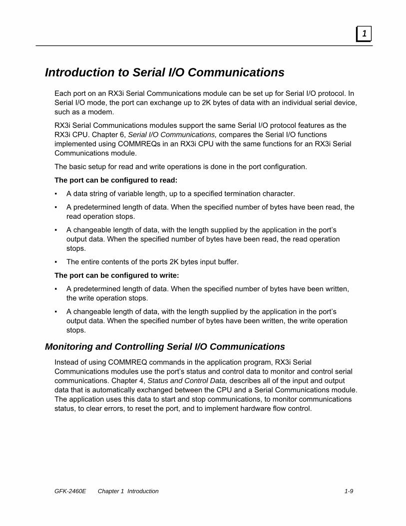
Introduction to Serial I/O Communications Each port on an RX3i Serial Communications module can be set up for Serial I/O protocol. In Serial I/O mode, the port can exchange up to 2K bytes of data with an individual serial device, such as a modem.
RX3i Serial Communications modules support the same Serial I/O protocol features as the RX3i CPU. Chapter 6, Serial I/O Communications, compares the Serial I/O functions implemented using COMMREQs in an RX3i CPU with the same functions for an RX3i Serial Communications module.
The basic setup for read and write operations is done in the port configuration.
The port can be configured to read:
A data string of variable length, up to a specified termination character.
A predetermined length of data. When the specified number of bytes have been read, the read operation stops.
A changeable length of data, with the length supplied by the application in the port’s output data. When the specified number of bytes have been read, the read operation stops.
The entire contents of the ports 2K bytes input buffer.
The port can be configured to write:
A predetermined length of data. When the specified number of bytes have been written, the write operation stops.
A changeable length of data, with the length supplied by the application in the port’s output data. When the specified number of bytes have been written, the write operation stops.
Monitoring and Controlling Serial I/O Communications Instead of using COMMREQ commands in the application program, RX3i Serial Communications modules use the port’s status and control data to monitor and control serial communications. Chapter 4, Status and Control Data, describes all of the input and output data that is automatically exchanged between the CPU and a Serial Communications module. The application uses this data to start and stop communications, to monitor communications status, to clear errors, to reset the port, and to implement hardware flow control.

1-10 PACSystems* RX3iSerial Communications Modules – June 2010 GFK-2460E
1
Introduction to CCM Slave Communications Each port on an RX3i Serial Communications module (revision 1.10 or later, and Proficy Machine Edition 5.6 SIM 6 or later) can be set up for CCM Slave protocol. CCM Slave protocol makes RX3i CPU data accessible to a variety of devices, such as Series 90-30 and Series 90-70 CCM and PCM modules. RX3i Serial Communications modules do not support CCM Master or peer-to-peer operation.
CCM Networks use the RS-232 / RS-422 communication standards. RS-422 is necessary for a multi-drop Master-Slave network. Communication is asynchronous, half-duplex at speeds up to 115.2K baud.
As a CCM Slave, an RX3i Serial Communications Module will respond to the CCM Master commands listed below. The Command Numbers listed in the left column are used in the Master’s application program to identify the command to be executed; they are not part of the CCM communication itself, and they are not relevant to the RX3i Serial Communications Module.
Master Command Number
Command Description
6101 Read from target to source register table
6102 Read from target to source input table
6103 Read from target to source output table
6109 Read Q-Response to source register table
6110 Single bit write.
6111 Write to target from source register table
6112 Write to target from source input table
6113 Writeto target from source Output Table
CCM Protocol defines additional commands that can be used by Masters or by other CCM devices. However, any CCM command that is not listed above cannot be processed by an RX3i Serial Communications module. That includes Local CCM commands that might be sent in COMMREQs by the RX3i CPU. The functions performed using Local CCM commands for other types of CCM modules are not used for RX3i Serial Communications Modules.
Implementation of CCM functions for an RX3i Serial Communications module is different from the implementation for other CCM devices. Chapter 7, CCM Communications, describes CCM for an RX3i Serial Communications module.

GFK-2460E Chapter 1 Introduction 1-11
1
Introduction to DNP3 Communications Distributed Network Protocol 3.0 (DNP3) Master and Slave protocols allow a PACSystems RX3i Serial Communications module to communicate with a variety of DNP3 devices.
Each port on an RX3i Serial Communications module (revision 1.20 or later, and Proficy Machine Edition 5.6 SIM 10 or later) can be set up for either DNP3 Slave or Master operation. When any port is configured for a DNP3 protocol, no other protocol can be used on the module. The other ports on the module can only be configured for DNP3 master or slave, or disabled.
DNP3 allows a master device to acquire information from and send control commands to slaves using relatively small-sized packets. A single change in any state or value can be exchanged between the master and slave without transferring the large amounts of unchanged data.
An RX3i Serial Communications Module DNP3 Master port or DNP3 Slave port supports the DNP3 functions listed below. See chapter 8 for specific details.
Function Master Port may issue
Slave Port will process
Slave Port may issue
Confirm
Read
Write
Select
Operate
Direct Operate
Direct Operate – No Acknowledgement
Cold Restart
Enable Unsolicited Reponses
Disable Unsolicited Reponses
Assign Class
Delay Measurement
Response
Unsolicited Response

1-12 PACSystems* RX3iSerial Communications Modules – June 2010 GFK-2460E
1
Introduction to Serial Protocol Language (SPL) Serial Protocol Language (SPL) is a simple, flexible scripting language designed for writing custom protocols. Each port on an RX3i Serial Communications module (revision 1.30 or later, and Proficy Machine Edition 5.8 SIM 2 or later) can be set up for SPL. The SPL custom protocol can be run concurrently with any of the module’s built-in protocols except DNP3. See chapter 9 for more information about Serial Protocol Language.
SPL Summary 32k bytes available for SPL script storage per port. 64 declarable integer variables per port.
variable name length may be up to 15 characters 32-bit signed integer
8 array variables per port. array variable name length may be up to 15 characters 1024 bytes in length
Integer math (signed) SPL script downloaded to the module from Proficy programmer One millisecond resolution timer supported per port. Immediate Command Line Interface commands – commands executed from the
command line to interact with the module and for debugging. Syntax to print to Command Line Interface port. The command prompt will display the port that it is controlling. ( Example: 2> ) Commands to facilitate debugging.
Program control statements – such as FOR, IF, GOTO Data manipulation statements – clearing variables, setting variables, etc… Serial port statements - reading, writing, etc… Checksum statements – syntax for CRC and BCC Logical and Math operators – OR, XOR, AND Syntax specifically for writing serial protocols. Exchange access – syntax to support getting and setting data in CPU registers.

GFK-2460E 2-1
Installation and Wiring
This chapter provides installation information for RX3i Serial Communications modules.
LEDs Module LEDs Port LEDs
Serial Ports Port Pin Assignments Built-in Termination
Point to Point Serial Connections RS-232 MODBUS
MODBUS Multidrop Connections Grounding and Ground Loops Multidrop Connections for Four-Wire MODBUS Multidrop Connections for Two-Wire MODBUS
For additional module installation and system installation information, please refer to the PACSystems RX3i System Manual, GFK-2314.
Chapter
2

2-2 PACSystems* RX3iSerial Communications Modules – June 2010 GFK-2460E
2
Installation in Hazardous Locations The information below applies to modules that are installed in hazardous locations. For more information about standards compliance, please refer to Appendix A of the PACSystems RX3i System Manual, GFK-2314.
EQUIPMENT LABELED WITH REFERENCE TO CLASS I, GROUPS A, B, C & D, DIV. 2 HAZARDOUS LOCATIONS IS SUITABLE FOR USE IN CLASS I, DIVISION 2, GROUPS A, B, C, D OR NON-HAZARDOUS LOCATIONS ONLY
WARNING - EXPLOSION HAZARD - SUBSTITUTION OF COMPONENTS MAY IMPAIR SUITABILITY FOR CLASS I, DIVISION 2;
WARNING - EXPLOSION HAZARD - WHEN IN HAZARDOUS LOCATIONS, TURN OFF POWER BEFORE REPLACING OR WIRING MODULES; AND
WARNING - EXPLOSION HAZARD - DO NOT CONNECT OR DISCONNECT EQUIPMENT UNLESS POWER HAS BEEN SWITCHED OFF OR THE AREA IS KNOWN TO BE NONHAZARDOUS.

GFK-2460E Chapter 2 Installation and Wiring 2-3
2
LEDs RX3i Serial Communications provide visual indication of module and port status with the LEDs described below.
Module LEDs
MODULE OK PORT FAULT
The Module OK LED indicates the status of the module. Off: The module is not receiving power from the RX3i
backplane, or the module has failed self test. Solid green: The module has been configured. Blinking green, rapidly: The module is executing powerup
diagnostics. Blinking green, slowly: The module has not received
configuration from the CPU. If configuration is not successful, the module will continue to flash in this mode.
Blinking amber: If a problem occurs, the Module OK LED flashes amber. The blink code indicates the cause of the error.
1 = watchdog expired 2 = RAM error 6 = Invalid CPU Master Interface version 7 = CPU heartbeat failure 8 = Failed to get semaphore
The Port Fault LED indicates the status of all ports. Green: There are no faults present on any enabled port. Amber: There is a fault on at least one port.
Port LEDs
STATUS
PORT 1
A port’s STATUS LED blinks green when there is activity on the port and the data rate matches the port configuration.
Recording Port Assignments
P1 P2: P3: P4:
The front of the module has an area where identifying information about each port should be written.

2-4 PACSystems* RX3iSerial Communications Modules – June 2010 GFK-2460E
2
Serial Ports RX3i Serial Communications modules provide either 2 or 4 identical serial ports that can be individually configured for RS-232 or RS-485 operation.
Port Pin Assignments Each port is a standard RJ-45 female connector with the following pin assignments. For MODBUS applications, note that these pin assignments are different than the standard MODBUS pin assignments. If the port is configured for MODBUS master or slave operation, custom cables are needed.
Pinouts RJ-45
Pin RS-232 DTE
RS-485/422 Two-Wire
RS-485/422 Four-Wire
8 COM GND GND 7 Termination 2 6 CTS Rx- (Input) 5 COM GND GND 4 Termination 1 3 RxD Rx+ (Input) 2 TxD Tx- / Rx Tx- (Output)
8
1
1 RTS/RFR Tx+ / Rx+ Tx+ (Output)
Note: There is no shield or frame ground pin on this connector.
GFK-2460E Chapter 2 Installation and Wiring 2-5
2
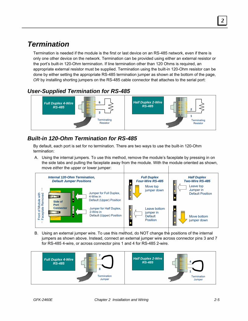
Termination Termination is needed if the module is the first or last device on an RS-485 network, even if there is only one other device on the network. Termination can be provided using either an external resistor or the port’s built-in 120-Ohm termination. If line termination other than 120 Ohms is required, an appropriate external resistor must be supplied. Termination using the built-in 120-Ohm resistor can be done by either setting the appropriate RS-485 termination jumper as shown at the bottom of the page, OR by installing shorting jumpers on the RS-485 cable connector that attaches to the serial port:
User-Supplied Termination for RS-485
6 3
Terminating Resistor
Full Duplex 4-Wire RS-485
2 1 Terminating
Resistor
Half Duplex 2-Wire RS-485
Built-in 120-Ohm Termination for RS-485 By default, each port is set for no termination. There are two ways to use the built-in 120-Ohm termination: A. Using the internal jumpers. To use this method, remove the module’s faceplate by pressing in on
the side tabs and pulling the faceplate away from the module. With the module oriented as shown, move either the upper or lower jumper:
Jumper for Full Duplex, 4-Wire in Default (Upper) Position
Jumper for Half Duplex, 2-Wire in Default (Upper) Position
Fron
t of M
odul
e w
ith
Face
plat
e R
emov
ed
Side of Port Connector
Move top jumper down
Leave bottom jumper in Default Position
Move bottom jumper down
Leave top Jumper in Default Position
Full Duplex Four-Wire RS-485
Half Duplex Two-Wire RS-485
Internal 120-Ohm Termination, Default Jumper Positions
B. Using an external jumper wire. To use this method, do NOT change the positions of the internal
jumpers as shown above. Instead, connect an external jumper wire across connector pins 3 and 7 for RS-485 4-wire, or across connector pins 1 and 4 for RS-485 2-wire.
7
3
Termination Jumper
Full Duplex 4-Wire RS-485
Termination Jumper
Half Duplex 2-Wire RS-485 4
1

2-6 PACSystems* RX3iSerial Communications Modules – June 2010 GFK-2460E
2
Connecting a Serial Communications Module to a Series 90-30 CPU363 or External PACSystems CPU
Rx- Rx+
RX3i CMM002/004 Module Built-in RS-485 Port
8GND
7NC5GND
4NC
3Rx+
2Tx-
1Tx+
6Rx-
9
1415
11
12 Tx-
13 Tx+
10
1
2
4
5
6
7
8
3
SIGNAL GROUNDNote: The same ground is required at each unit. Use either or both GND connectors (pins 8 and 5.)
* To provide termination using an external resistor, connect a user-supplied resistor across pins 10 and 11.** To provide termination using the built-in 120Ω resistor,
install a jumper between pins 9 and 10.
For additional port details, refer to the documentation for the CPU.
If the CMM002/004 module is the first or last device on the RS-485 network, termination must be provided using an external resistor or the port’s built-in 120-Ohm termination. For details, see “Termination” in this document.
*
**
Signal Name Description Direction
Tx+ Transmitted Data + Output Tx- Transmitted Data - Output Rx+ Received Data + Input Rx- Received Data - Input

GFK-2460E Chapter 2 Installation and Wiring 2-7
2
Point to Point Serial Connections When the network has only one slave device, a point-to-point connection between the master and slave is used. The cable connection may be either RS-232 or RS-485.
RS-232 MODBUS RS-232 MODBUS should only be used for shorter distances, typically less than 20 meters. MODBUS Devices that use an RS-232 interface define the following connections:
Signal Description For DCE Required for MODBUS
Common Signal Common -- yes
CTS Clear to Send In
RTS Request to Send Out
RxD Received Data In yes
TxD Transmitted Data Out yes
Each TxD must be wired with the RxD of the other device.
RS-232 bus cable should not be terminated.
RS-232 Compliant Device RX3i, RX7i, Series 90, VersaMax Modular VersaMax
Micro/Nano
DB-9 Male Connector
DB-25 Male
Connector
DB-9 Female
Connector
DB-25 Female
Connector (CMM)
RJ-11 Connector
RJ-45 Connector
RJ-45 Connector
5 7 5 7 4 8 8
7 4 8 4 6 1 1 5 7 5 7 3 5 8
3 2 2 2 2 2 4 2 3 3 3 5 3 3 8 5 7 5 1 6 2
Use these optional connections if hardware handshaking is required
COM (GND) CTS COM (GND) RxD TxD RTS
COM (GND)
RTS COM (GND)
TxD RxD CTS
8
1
RJ-45 Connector
8 7 6 5 4 3 2 1
RX3i Serial Communications Module
(RS-232)
Can use either or both of these COM
connections

2-8 PACSystems* RX3iSerial Communications Modules – June 2010 GFK-2460E
2
MODBUS Multidrop Connections For a multidrop MODBUS connections in an RS-485 system, either two-wire or four-wire:
At least 32 devices can be used without a repeater. Depending on the load and the line polarization (see below), more devices may be possible without a repeater. Repeaters can be used when more devices are required.
An RS-485 MODBUS serial line without a repeater has one trunk table. Devices can be connected either directly or using short branch cables (up to 20 meters).
If a multi-port tap is used, each branch has a maximum length of 40 meters divided by the number of branches fed by that tap.
The length of the bus cable depends on the baud rate, the number of loads, the type of cable, and the network configuration. For a maximum 9600 baud rate and AWG28 or larger cable, the maximum length is 1000 meters. AWG24 is always sufficient for MODBUS data. Category 5 cables may be used up to a maximum length of 600 meters. In a system where four-wire cabling is used in a two-wire system as shown in this section, the maximum cable length must be divided by 2.
For the balanced pairs in an RS-485 system, a characteristic impedance above 100 Ohms is preferred, especially for baud rates of 19200 and above.
The line must be terminated near both ends of the bus trunk cable, between the D0 and D1 conductors of the balanced line. Termination must not be placed on a branch cable. 150 Ohm, 1/2W resistors can be used for termination. In a four-wire system, each pair must be terminated at each end of the bus.
The signal and optional power supply common signal must be connected directly to protective ground, preferably at one point only. This is usually done at the master or its tap.

GFK-2460E Chapter 2 Installation and Wiring 2-9
2
Grounding and Ground Loops Proper grounding of the cable shield requires careful planning of the network and its power wiring. To avoid data errors from intermittent electrical noise, the cable shield must be grounded to earth ground at every device on the network. Unfortunately, this introduces at least N-1 ground loops, where N is the number of devices on the network. Each ground loop path comprises the shield and drain wire on the cable segment between two devices and a ground return path. The return paths start at the frame ground point of one device, pass through its ground conductor to the common ground, and then pass through the ground conductor of the other device to its frame ground point.
Ground loop currents must be kept within acceptable limits by careful grounding. Otherwise, common-mode noise induced on the data pair by the ground loop currents can cause data errors.
When designing ground wiring, consider these requirements:
1. There must be one common ground point in the system with an extremely low impedance path to earth.
2. The conductor from the frame ground point of each device to the common ground must have extremely low impedance.
3. The recommended frame ground wire sizes, lengths and proper wiring practices must be observed in designing the connections between frame ground points and the common ground.
4. The data cable and ground wire routing must be physically isolated from other wiring that could couple noise onto the data cable or ground wiring.
5. If disconnecting the cable shield from earth ground at any device reduces data errors, the network has a ground loop issue. Connecting cable shields at one end only to eliminate ground loop currents is not recommended because it increases the network’s susceptibility to intermittent data errors from electromagnetic interference (EMI). Such errors can be difficult to detect and costly to correct.
If data errors caused by ground loops cannot be avoided (for example, because the cable run is too long for all devices to use a common ground point), add one or more optically isolated RS-485 repeaters to the network. Partition the network into segments so that each segment has a common ground. Isolate the segments with repeaters.

2-10 PACSystems* RX3iSerial Communications Modules – June 2010 GFK-2460E
2
Multidrop Connections for Four-Wire MODBUS Four-wire bus cable includes two pairs of communications lines and a common line. Data on the master pair (RxD1-RxD0) is received by only the master. Data on the slave pair (TxD1-TxD0) is received by only the slaves. Only one driver at a time has the right to transmit.
The MODBUS slave devices must all use RS-485-compatible serial ports so that their transmitters are disabled except when transmitting. Although some RS-422 devices disable outputs when not transmitting, the RS-422 specification does not require it. The master may use either RS-422 or RS-485 because it is the only transmitter on that pair.
Any high-quality shielded twisted-pair cable with two pairs is suitable for short cable runs (up to about 15 meters) without repeaters. Longer runs require a cable with a suggested nominal impedance of 120 ohms.
Both signal pairs must be terminated at both ends by a suggested 120-ohm, ¼ watt resistor across the RxD signal pair.
MODBUS Master
Slave Slave
Slave Pair
Common
Termination
Termination
TxD1
TxD0
Master Pair Termination
Termination
RxD1
RxD0
RxD
1 R
xD0
TxD
1 Tx
D0
RxD
1 Tx
D1
RxD
0 Tx
D0
RxD
1 Tx
D1
RxD
0 Tx
D0

GFK-2460E Chapter 2 Installation and Wiring 2-11
2
Connecting the Master Using a Passive Tap Four-wire cable must cross the two pairs on the bus between the bus interface and the passive bus tap on the master. This may be done with crossed cables, but the recommended way to connect a 4-wire master device is to use a tap that provides a crossing capability.
Signal on Master Interface to Passive Tap Type RS-485 Signal on
Trunk Interface
RxD1 In B’ TxD1 Slave Pair
RxD0 In A’ TxD0
TxD1 Out B RxD1 Master Pair
TxD0 Out A RxD0
Connecting Two-Wire Devices in a Four-Wire System Two-wire devices can be connected to a four-wire system as shown below. In this example, the master and slave 1 use a four-wire interface. Slaves 2 and 3 use a two-wire interface.
MODBUS
Master
Slave 1
Slave 2
Slave Pair
Common
Termination
TxD1
TxD0
Master Pair Termination
RxD1
RxD0
Slave3
RxD
1 Tx
D1
RxD
0 Tx
D0
D1 D0
D1 D0
RxD
1 R
xD0
TxD
1 Tx
D0
The TxD0 signal must be wired to the RxD0 signal, turning them into the D0 signal.
The TxD1 signal must be wired to the RxD1 signal, turning them into the D1 signal.

2-12 PACSystems* RX3iSerial Communications Modules – June 2010 GFK-2460E
2
Multidrop Connections for Two-Wire MODBUS On a two-wire network, the Transmit Data (TxD) and Receive Data (RxD) pairs of all devices are connected in parallel to a single pair of wires. Both ends of the pair must be terminated with 120-ohm resistors. All devices must be RS-485-compatible, in order to disable their transmitters except when transmitting. All devices must disable their receivers while transmitting.
The signal pair must be terminated at both ends. If either end device lacks a built-in terminator, a recommended 120-ohm, ¼ watt resistor must be wired across the signal pair inside the connector shell.
Any high-quality shielded twisted-pair cable is suitable for short cable runs (up to about 15 meters). Longer runs require a cable with a suggested nominal impedance of 120 ohms. Use a cable designed for RS-485 transmission.
Serial ports on all devices should be configured for Flow Control NONE.
RS-485 repeaters can also be used on 2-wire networks.
Connections for Two-Wire Devices Two-wire bus cable includes two communications lines and a common line. Only one driver at a time has the right to transmit.
MODBUS Master
Slave Slave
Balanced Pair
Common
Termination
Termination
D1
D0

GFK-2460E Chapter 2 Installation and Wiring 2-13
2
Connecting Four-Wire Devices to a Two-Wire Network Four-wire devices can be connected to a two-wire network as shown below. In this example, the master and slave 1 use a two-wire interface. Slaves 2 and 3 use a four-wire interface.
MODBUS Master
Slave 1
Balanced Pair
Common
Termination
Termination
D1
D0
Slave2
Slave3
RxD
1 R
xD0
TxD
1 Tx
D0
RxD
1 R
xD0
TxD
1 Tx
D0
For each four-wire device:
The TxD0 signal must be wired with the RxD0 signal, then connected to the D0 signal on the trunk.
The TxD1 signal must be wired with the RxD1 signal, then connected to the D1 signal on the trunk.


GFK-2460E 3-1
Configuration
This chapter describes the configurable parameters of PACSystems RX3i Serial Communications modules.
Configuring Basic Module Settings
I/O Settings
General Settings
Configuring a Port for Serial I/O Protocol
Configuring a Port for MODBUS Master Protocol
Configuring a Port for MODBUS Slave Protocol
Configuring a Port for CCM Slave Protocol
Configuring a Port for DNP3 Master Protocol
Configuring a Port for DNP3 Slave Protocol
Configuring a Port for Serial Protocol Language (SPL)
Chapter
3

3-2 PACSystems* RX3iSerial Communications Modules – June 2010 GFK-2460E
3
Configuring Basic Module Settings Machine Edition version 5.5 with Service Pack 2 SIM 4 or later is required for basic configuration of an RX3i Serial Communications Module. Some protocols require later programmer versions, as noted in the individual protocol configuration sections in this chapter. It is strongly recommended that the latest version of Machine Edition be used.
Click on the slot, and right-click to Add a Module. From the module catalog, select either of the following from the list of Communications Modules: IC695CMM002: RX3i Serial Communications Module (2 ports) IC695CMM004: RX3i Serial Communications Module (4 ports)
For the module, configure the following settings:
I/O Settings These parameters assign CPU reference memory for the port’s status and control data, which is used to monitor and control communications activities on the port. This CPU reference memory is not used for the actual communications data. CPU reference memory for that data is assigned in a separate step. Port [1, 2, 3, 4] Status Data Reference and Length: This reference location can be %I, %M, or %T memory. For each port, the length is fixed at 224 bits. Port [1, 2, 3, 4] Control Data Reference and Length: The reference location can be %Q, %M, or %T memory. For each port, the length is fixed at 128 bits. If retentive memory (%Q or %M may optionally be set up to be retentive, %T is non-retentive) is used for Port Control Data, when a power cycle with battery or hot swap occurs, the control data remains in memory and is executed by the module on the next PLC output scan or output DO I/O unless that data is cleared by application logic.
General Settings I/O Scan Set: Selecting I/O Scan 1 guarantees that the module’s Port Status and Port Control data will be exchanged every I/O Scan. However, any scan set from 1 to 32 can be chosen.

GFK-2460E Chapter 3 Configuration 3-3
3
Configuring a Port for Serial I/O Protocol To set up a port for Serial I/O protocol, on the Port tab, set Protocol to Serial I/O, then configure the additional port parameters for Serial I/O as described below.
Serial Port Settings Data Rate: Default: 19.2k. Choices are 1200, 2400, 4800, 9600, 19.2k, 38.4k , 57.6k, and 115.2k Baud.
Data bits: Choices 7, 8.
Parity: None, Odd, Even.
Stop Bits: Default is 1. Choices: 1, 2.
Timeout (mS): Defaults to 100. Range is 0 to 65535ms. If the module is expecting to receive data and it hasn’t received data before this assigned timeout period, a receive timeout error occurs for the exchange being processed. If there is data to be transmitted and the hardware handshaking isn’t allowing data to be transmitted (CTS not asserted when in RS232 mode with Hardware Control configured) for the assigned timeout value, a transmit error occurs for the exchange being processed.
Port Type: RS232, RS485 (2 wire), RS485 (4 wire).
Flow Control: (for RS232 only): Default is none. If Hardware Control is selected, RTS and CTS will be used to control serial transmission flow, and the module will be able to control the flow of data without losing any data bytes. See chapter 6 for more information about managing Hardware Flow Control for RS232 communications.
Flow Control Duplex: (for RS232 only). Default is Full Duplex. Choices are Full Duplex or Half Duplex.
Tx/RTS Drop Delay: defaults to 0. Range 0 to 15. This is the time from the end of the last transmitted character to the time when RTS is turned off (dropped). A Drop Delay may be needed for some modem communication with RTS and long-distance RS485 connections. For RS232 with Flow Control, a suitable Drop Delay should be configured.

3-4 PACSystems* RX3iSerial Communications Modules – June 2010 GFK-2460E
3
Port Config ID Setting User Config ID: Default is 1, range is 0 to 255. Use of a configuration ID is optional. If a User Config ID is configured, the module returns it to the CPU in each sweep of its Port Status data (see chapter 4, Port Status and Control Data). This feature might be used in an application where the same application logic is used with different configurations.
Serial I/O Port Data If the protocol selected for a port is Serial I/O, configure the following parameters on the corresponding PortData_Serial I/O tab.
Checksum Configuration Validate Receive Checksum: the default is No Receive Checksum. If Validate Checksum is configured, the module will automatically calculate a checksum on the data. If the calculated checksum does not match the checksum at the end of the received data, the module will not pass the data to the CPU. The checksum byte(s) are not sent with the data to the CPU if a checksum is calculated.
Append Transmit Checksum: the default is No Transmit Checksum. If the message should have a transmit checksum, select Append Transmit Checksum to End of Message, and specify the checksum type below.
Checksum Type: The default is CRC16. The module will calculate a 16-bit Cyclic Redundancy Check across all data, not including any end delimiters. If BCC is selected, the module will calculate a Block Check Character by doing an XOR of all data bytes.
Note: The CMM module calculates the CRC16 value based on the polynomial x16+x15+x2+1 and returns it in byte swapped format. For example, for the hex value 01 07, the CMM returns the CRC16 value 41 E2.

GFK-2460E Chapter 3 Configuration 3-5
3
Serial I/O Read Configuration Read Control Operation. The default is Receiving Disabled. The other choices are: Read Delimiter, Byte Count.
Receiving Disabled: prevents Serial I/O read operations through the port. If Receiving Disabled is selected, a receive transaction will only read data bytes that are already in the port’s internal Receive Buffer (up to 2KB). The number of bytes actually read will be indicated in the byte 24 (bits 177 – 192) of the port’s input status data.
Read Delimiter: if Read Delimiter is selected, the data in the port’s Input Buffer will be searched for the first occurrence of the configured Read End Delimiter terminating character(s). When the Read End Delimiters are found, the data is transferred to the CPU without the terminating characters. If the terminating characters cannot be found, the receive operation will be terminated after the timeout period has expired. The module will set the Exchange Error Report bit (bit 65 of the port’s status data) to 1 and byte 24 (bits 177 – 192) of the port’s input status data to 0.
Byte Count: if Byte Count is selected, a static or dynamic number of bytes will be read, depending on the additional choices below. Once the number of bytes selected is received, the data is transferred to the CPU.
Read Serial I/O Memory Area: the CPU reference area for data read from the serial device. Possible memory types are: %AI, %AQ, %R, %M, %Q, or %I.
Read Serial I/O Data Length: the length in 8-bit increments or 16-bit words, as appropriate, for the CPU reference area that will be used for Serial I/O read data. The length must accommodate the largest amount of data that may be read in one transaction.

3-6 PACSystems* RX3iSerial Communications Modules – June 2010 GFK-2460E
3
Read Length Source: If Read Control Operation is set to Byte Count, and the length of the data will not always be the same, select Dynamic Read Length. When Dynamic Read Length is selected, the application program must supply the read length in bits 97-112 of the Port Control output data it sends to the module each I/O Scan. If the data length to read will always be the same, select Static Read Length.
Static Read Length: If Read Control Operation is set to Byte Count, and the length of data to be read using Serial I/O Protocol will always be the same, enter the number of bytes to be read. The range is 0 to 2048 (2K bytes), which is the total amount of data in the buffer. If the length is set to 0, the module will send the CPU all of the data in the port’s input buffer.
Read End Delimiters: If Read Control Operation is set to Read Delimiter, configure the end delimiters using up to 4 ASCII characters separated by commas or spaces. During operation, the module will scan the incoming data for this combination of characters, and will receive the data once the terminating characters are found. The terminating characters may be any combination of individual characters: a-z, A-Z, 0-9, or as hexadecimal characters. For example:
0x41,a,b,c
a a
0x41
0x41 0x42 0x43 0x44
Because either commas or spaces can be used to separate characters when configuring the values, if a comma is desired as a delimiter, its ASCII hex code should be used.
When the hardware configuration is validated, any non-hexadecimal characters that have been entered in the configuration are automatically converted to their hexadecimal equivalents as shown below for the example values:
0x41,a,b,c is converted to: 0x41 0x61 0x62 0x63
a a is converted to: 0x61 0x61
0x41 remains: 0x41
0x41 0x42 0x43 0x44 remains: 0x41 0x42 0x43 0x44

GFK-2460E Chapter 3 Configuration 3-7
3
Serial I/O Write Configuration Write Control Operation: Default is Transmitting Disabled. Alternative is Transmitting Enabled.
For Transmitting Enabled, configure the additional parameters shown.
Write Serial I/O Memory Area: Specify the beginning reference in CPU memory for the data that will be written to the serial device. Memory types are: %AI, %AQ, %R,%M, %Q, %I.
Write Serial I/O Data Length: Default is 0. Range is 0 to 1024. The length in 8-bit increments or 16-bit words, as appropriate, for the CPU reference area that will be used for Serial I/O transmitted data. The length must accommodate the largest amount of data that may be sent in one transaction.
Write Length Source: If the same length of data will always be written, choose Static Write Length and enter a value below. If the write length may change, choose Dynamic Write Length (Found in Output Scan Data). The CPU must then provide the data length in bits 113-128 of the Port Control output data it sends to the module each I/O Scan.
Static Write Length: Default is 0. Range is 0 to 2048 (2K bytes), which is the maximum amount of data the write buffer can contain.

3-8 PACSystems* RX3iSerial Communications Modules – June 2010 GFK-2460E
3
Configuring a Port for MODBUS Master Protocol On the port tab, set Protocol to MODBUS Master, then configure the additional port parameters as described below.
Serial Port Settings Data Rate: Default: 19.2k Baud. Choices are 1200, 2400, 4800, 9600, 19.2k, 38.4k , 57.6k, 115.2k Baud.
Data bits: Always 8 for MODBUS Master.
Parity: None, Odd, Even. When parity = ODD or EVEN, the character length used by MODBUS Master is 10 bits: one start bit, 8 data bits, one parity bit and one stop bit. There is no parity bit when parity = NONE, and the character length is 9 bits. The selection should match the parity used by other devices on the network.
Stop Bits: Default is 1. Choices: 1, 2. If Parity is set to Odd/Even, the number of Stop Bits should be 1. If Parity is set to None, the number of Stop Bits should be set to 2 for most applications. Some non-conforming MODBUS slaves may require the stop bits to be set to 1 for compatibility.
Timeout (mS): Range is 0 to 65535ms. An error will be reported to the status location if this timeout expires before a complete response is received. MODBUS requires a timeout in all cases. A 500 milliseconds timeout is recommended by the MODBUS standard. If no valid response from the slave is detected after the configured timeout period, an error code is returned to the status location.
Port Type: RS232, RS485 (2 wire), RS485 (4 wire)

GFK-2460E Chapter 3 Configuration 3-9
3
Flow Control: (for RS232 only) Default is none. Choices are None, Hardware Control (RTS/CTS). If Hardware Control is specified, the port will assert RTS, then wait for CTS to become active before transmitting. If CTS does not become active within 2 seconds, a time-out error code is returned to the status location.
If CTS becomes active and then is de-asserted while the port is transmitting, up to 5 milliseconds may elapse before transmission stops. The maximum number of characters transmitted after CTS is de-asserted is proportional to the data rate. These values are in addition to the character that is being transmitted at the time CTS is de-asserted.
Flow Control Duplex: (for RS232 only). Default is Full Duplex. Choices are Full Duplex or Half Duplex.
Tx/RTS Drop Delay (bit times), defaults to 0. Range 0 to 15 bit times. This is the time from the end of the last transmitted character to the time when RTS is turned off (dropped).
The receiver is disabled during transmission and remains disabled during the RTS drop delay time. If the specified delay is longer than the MODBUS Slave’s silent interval between the query and its response, the master will ignore all or part of the response.
Outputs Disabled Control: Default is Stop Processing Exchanges. Alternative is Continue Processing Exchanges. This option applies to continuous read and write exchanges. It does not apply to bit-controlled continuous exchanges or to single exchanges.
Port Config ID Setting User Config ID: Default is 1, range is 0 to 255.

3-10 PACSystems* RX3iSerial Communications Modules – June 2010 GFK-2460E
3
Configuring MODBUS Master Exchanges If the protocol selected for a port is MODBUS Master, configure up to 64 data exchanges on the corresponding PortData_Modbus Master tab. Based on the selections made on this screen, the Serial Communications module will execute the appropriate, standard MODBUS functions.
When configuring master exchanges, remember that read exchanges will read data from the slave target and write it to the specified reference address. Write exchanges will read data from the specified reference address and write it to the slave target. Looking at the fields on the exchange configuration screen, read data “flows” from the target memory to the configured reference address. Write data “flows” from the configured reference address to the target memory.
Operation: This parameter sets up how the MODBUS Master function will be performed. The default for each exchange is Disabled. Options are described below.
1. Read Continuous: This type of exchange repeatedly reads the specified data from the target slave and places it into the assigned CPU reference addresses. The CPU does not control this exchange. It only stops when PLC outputs are disabled (if the Outputs Disabled parameter on the Port tab is set to disable continuous exchanges when outputs are disabled.
2. Read Continuous Bit-Control: This type of exchange must be started by setting a bit in the CPU (see chapter 4 for details). The module then periodically reads the specified data from the slave until commanded to stop by clearing the same bit.

GFK-2460E Chapter 3 Configuration 3-11
3
3. Read Single Bit-Control: This type of exchange must be initiated by setting a bit in the CPU (see chapter 4 for details). The module reads the specified data once each time the control bit transitions.
4. Write Continuous: This type of exchange repeatedly writes the specified bit or word data from the assigned CPU references to the slave’s Coils (0x) or Holding Registers (4x) table. The CPU does not control this exchange. It only stops when PLC outputs are disabled (if the Outputs Disabled parameter on the Port tab is set to disable continuous exchanges when outputs are disabled.
5. Write Continuous Bit-Control: This type of exchange must be started by setting a bit in the CPU (see chapter 4 for details). The module then periodically writes the specified data to the slave until commanded to stop by clearing the same bit.
6. Write Single Bit-Control: This type of exchange must be initiated by setting a bit in the CPU (see chapter 4 for details). The module writes the specified data once each time the control bit transitions.
Station Address: Specify the MODBUS Device ID from of the slave associated with the exchange. For Read operations, the range of Device IDs is 1 to 247. For Write operations, the range of Device IDs is 0 to 247. If the MODBUS query should be broadcast to all slaves, enter 0 as the Device ID.
Target Type: Select the type of data to be exchanged: MODBUS Coils (0x), MODBUS Discrete Inputs (1x), MODBUS Holding Registers (3x), MODBUS Input Registers (4x), MODBUS Query data, or Diagnostic Status data.
If Diagnostic Status is selected, the CPU can use this exchange to read from the Serial Communications Module a set of Diagnostic Status words for the port. See chapter 4 for details of the Diagnostic Status words.
If Return Query Data is selected, the CPU will use this exchange to automatically perform MODBUS function 08, Subfunction 00, Read Query Data. The module sends two bytes of data to the specified Slave Address, Target Type and Target Address, to see whether the slave echoes the data back. The data that is sent will be two bytes from the configured Reference Address. The content of the data is not meaningful.

3-12 PACSystems* RX3iSerial Communications Modules – June 2010 GFK-2460E
3
Target Address: For MODBUS data, this is the starting address in the MODBUS table selected as the Target Type.
For Diagnostic Status Data, this is the first word of Diagnostic Status data to be read from the module. For example, entering a Target Address of 1 would access Word 1 of the Diagnostic Status data, which is the MODBUS Errors status word, as detailed in chapter 4.
Reference Address: Specify the CPU memory type and starting address for the data to be read or written in the Data Exchange. To select a memory type and starting address, double-click on the Ref Address field or right-click and select Data Entry Tool.
Select a
starting address
Select a memory type
Available references
If the Data Exchange Target Type is Return Query, this reference should specify the start of two bytes of data to be sent to the specified slave. The content of the data is not meaningful, its purpose is to verify the slave’s data to return the query.
Reference Length: Specify the length of the memory area selected above in bits or 16-bit words (registers). The default is 0. Range is 1 to 127 words or 1 to 2040 bits. For Diagnostic Status, this is fixed at 18 words (240 bits). For a Return Data Query, the length of this data area should be 16 bits (1 word).
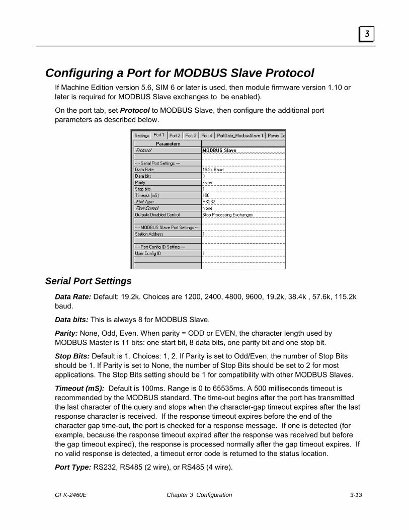
GFK-2460E Chapter 3 Configuration 3-13
3
Configuring a Port for MODBUS Slave Protocol If Machine Edition version 5.6, SIM 6 or later is used, then module firmware version 1.10 or later is required for MODBUS Slave exchanges to be enabled).
On the port tab, set Protocol to MODBUS Slave, then configure the additional port parameters as described below.
Serial Port Settings Data Rate: Default: 19.2k. Choices are 1200, 2400, 4800, 9600, 19.2k, 38.4k , 57.6k, 115.2k baud.
Data bits: This is always 8 for MODBUS Slave.
Parity: None, Odd, Even. When parity = ODD or EVEN, the character length used by MODBUS Master is 11 bits: one start bit, 8 data bits, one parity bit and one stop bit.
Stop Bits: Default is 1. Choices: 1, 2. If Parity is set to Odd/Even, the number of Stop Bits should be 1. If Parity is set to None, the number of Stop Bits should be set to 2 for most applications. The Stop Bits setting should be 1 for compatibility with other MODBUS Slaves.
Timeout (mS): Default is 100ms. Range is 0 to 65535ms. A 500 milliseconds timeout is recommended by the MODBUS standard. The time-out begins after the port has transmitted the last character of the query and stops when the character-gap timeout expires after the last response character is received. If the response timeout expires before the end of the character gap time-out, the port is checked for a response message. If one is detected (for example, because the response timeout expired after the response was received but before the gap timeout expired), the response is processed normally after the gap timeout expires. If no valid response is detected, a timeout error code is returned to the status location.
Port Type: RS232, RS485 (2 wire), or RS485 (4 wire).

3-14 PACSystems* RX3iSerial Communications Modules – June 2010 GFK-2460E
3
Flow Control: (for RS232 only) Default is none. Choices are None, or Hardware Control (RTS/CTS). If Hardware Control is specified, the port will assert RTS, then wait for CTS to become active before transmitting. If CTS does not become active within 2 seconds, a time-out error code is returned to the status location.
If CTS becomes active and then is de-asserted while the port is transmitting, up to 5 milliseconds may elapse before transmission stops. The maximum number of characters transmitted after CTS is de-asserted is proportional to the data rate. These values are in addition to the character that is being transmitted at the time CTS is de-asserted.
Flow Control Duplex: (for RS232 only). Default is Full Duplex. Choices are Full Duplex or Half Duplex.
Tx/RTS Drop Delay (bits). For RS485, or RS232 with Flow Control, defaults to 0. Range 0 to 15 bits. RS232This is the time from the end of the last transmitted character to the time when RTS is turned off (dropped).
Outputs Disabled Control: Default is Stop Processing Exchanges. Alternative is Continue Processing Exchanges.
MODBUS Slave Port Settings If the Protocol Type is Modbus Slave only, select the Station Address of the slave (port). Range is 1 to 247
Port Config ID Setting User Config ID: Default is 1, range is 0 to 255.

GFK-2460E Chapter 3 Configuration 3-15
3
Automatic MODBUS Slave Exchanges Proficy™ Machine Edition 5.6 SIM 6 or later provides a set of default Data Exchanges that will automatically accommodate all supported MODBUS queries from the master. By default, when the port is set up for MODBUS Slave operation, a set of predefined Data Exchanges map MODBUS addresses to PACSystems CPU reference addresses. When the default Data Exchanges are used, no additional slave exchanges need to be configured. Following are the RX3i addresses that correspond to MODBUS functions that may be received by the slave port:
Read Input Registers: %AI Read Holding Registers: %R Preset Single Register: %R Preset Multiple Registers: %R Mask 4X Registers: %R Read/Write 4X Registers: %R Read Input Status: %I Read Coils Status: %Q Force Single Coil: %Q Force Multiple Coils: %Q
Changed Implementation of MODBUS Slave Exchanges Earlier versions of Machine Edition, such as Machine Edition 5.5 with Service Pack 2 SIM 4, implemented MODBUS Slave Exchanges using the Preconfigured Exchanges field on the port configuration tab. Selecting Preconfigured Exchanges set up the automatic mapping described above, but prevented configuration of additional Data Exchanges for the port. With Machine Edition 5.6 SIM 6 or later, the Preconfigured Exchanges field is no longer available. The function is replaced by the preconfigured Data Exchanges, which provide greater configuration flexibility, as described below.
Customizing MODBUS Slave Exchanges The default Data Exchanges in Machine Edition 5.6 SIM 6 or later permit the MODBUS Master to read all of the %I, %AI, %Q, and %R references and to write all of the %Q and %R references in the PACSystems RX3i CPU.
The default exchanges can be edited, and new Data Exchanges can be defined, in order to:
Read or write additional reference types: %AI, %AQ, %R, %W, %M, %Q, %T, %I
Prevent the MODBUS Master from writing to some or all memory in the RX3i CPU
Limit MODBUS Master access to certain memory areas and types
Target specific data items to be read or written.
The process of creating custom Data Exchanges is explained in this chapter.
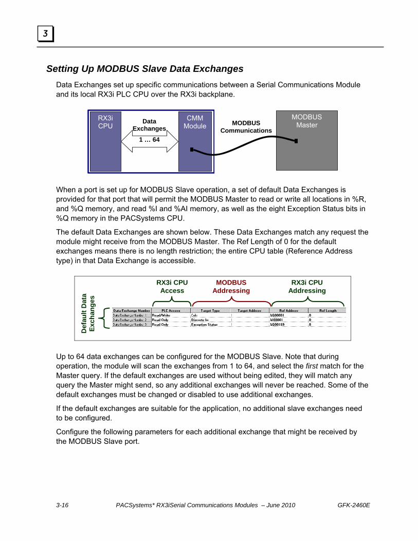
3-16 PACSystems* RX3iSerial Communications Modules – June 2010 GFK-2460E
3
Setting Up MODBUS Slave Data Exchanges Data Exchanges set up specific communications between a Serial Communications Module and its local RX3i PLC CPU over the RX3i backplane.
RX3i CPU
CMM Module
Data Exchanges
1 … 64
MODBUS Master MODBUS
Communications
When a port is set up for MODBUS Slave operation, a set of default Data Exchanges is provided for that port that will permit the MODBUS Master to read or write all locations in %R, and %Q memory, and read %I and %AI memory, as well as the eight Exception Status bits in %Q memory in the PACSystems CPU.
The default Data Exchanges are shown below. These Data Exchanges match any request the module might receive from the MODBUS Master. The Ref Length of 0 for the default exchanges means there is no length restriction; the entire CPU table (Reference Address type) in that Data Exchange is accessible.
MODBUS Addressing
RX3i CPU Addressing
RX3i CPU Access
Def
ault
Dat
a Ex
chan
ges
Up to 64 data exchanges can be configured for the MODBUS Slave. Note that during operation, the module will scan the exchanges from 1 to 64, and select the first match for the Master query. If the default exchanges are used without being edited, they will match any query the Master might send, so any additional exchanges will never be reached. Some of the default exchanges must be changed or disabled to use additional exchanges.
If the default exchanges are suitable for the application, no additional slave exchanges need to be configured.
Configure the following parameters for each additional exchange that might be received by the MODBUS Slave port.
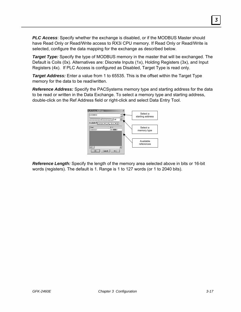
GFK-2460E Chapter 3 Configuration 3-17
3
PLC Access: Specify whether the exchange is disabled, or if the MODBUS Master should have Read Only or Read/Write access to RX3i CPU memory. If Read Only or Read/Write is selected, configure the data mapping for the exchange as described below.
Target Type: Specify the type of MODBUS memory in the master that will be exchanged. The Default is Coils (0x). Alternatives are: Discrete Inputs (1x), Holding Registers (3x), and Input Registers (4x). If PLC Access is configured as Disabled, Target Type is read only.
Target Address: Enter a value from 1 to 65535. This is the offset within the Target Type memory for the data to be read/written.
Reference Address: Specify the PACSystems memory type and starting address for the data to be read or written in the Data Exchange. To select a memory type and starting address, double-click on the Ref Address field or right-click and select Data Entry Tool.
Select a
starting address
Select a memory type
Available references
Reference Length: Specify the length of the memory area selected above in bits or 16-bit words (registers). The default is 1. Range is 1 to 127 words (or 1 to 2040 bits).

3-18 PACSystems* RX3iSerial Communications Modules – June 2010 GFK-2460E
3
Configuring a Port for CCM Slave Protocol Machine Edition 5.6 SIM 6 or later is required for CCM Slave protocol configuration. On the port tab, set Protocol to CCM Slave, then configure the additional port parameters as described below.
Serial Port Settings Data Rate: Default: 19.2k. Choices are 1200, 2400, 4800, 9600, 19.2k, 38.4k , 57.6k, 115.2k baud. Choose a baud rate that matches that used by the CCM Master. Note that RX3i Serial Communications modules do not support the 300 and 600 baud data rates of CCM hardware modules, such as the Series 90-30 CMM311, and CCM hardware modules do not support the faster data rates that are available on RX3i Serial Communications modules. Data rates of 1200 baud through 19.2K baud should be compatible with all modules.
Data bits: CCM protocol always uses eight data bits and one stop bit.
Parity: None, Odd, Even. Default is odd.
Stop Bits: Default is 1. CCM protocol always uses eight data bits and one stop bit.
Timeout: For CCM, there are eight predefined timeouts (see chapter 7) conditions. The overall timeout period is the sum of these eight timeouts, plus the configured Turn Around Delay, plus the Timeout in milliseconds configured here. If the Timeout value for CCM protocol is set to 0, timeouts are NOT disabled.
Port Type: RS232, RS485 (2 wire), or RS485 (4 wire). CCM Hardware Modules use the RS232 or RS422 communication standards. An RX3i Communications Module can be configured for RS232 or RS485. RS485(4-wire mode) is backward compatible to RS422

GFK-2460E Chapter 3 Configuration 3-19
3
allowing the RX3i Communications Module to be used on CCM RS422 networks. Refer to the hardware specification for more information.
Flow Control: (for RS232 only) Default is none. Choices are None, or Hardware Control (RTS/CTS). If Hardware Control is specified, the port will assert RTS, then wait for CTS to become active before transmitting. If CTS does not become active before the timeout period expires, an error code (0x1A) is set in the Diagnostic Status data. If the exchange number is known when the error occurs, error code 0x1A is also set in the Exchange Error location.
If CTS becomes active and then is de-asserted while the port is transmitting, up to 5 milliseconds may elapse before transmission stops. The maximum number of characters transmitted after CTS is de-asserted is proportional to the data rate. These values are in addition to the character that is being transmitted at the time CTS is de-asserted.
Flow Control Duplex: (for RS232 only). Default is Full Duplex. Choices are Full Duplex or Half Duplex.
Tx/RTS Drop Delay (bits), defaults to 0. Range 0 to 15 bit times. For RS485, or RS232 with Flow Control. This is the time from the end of the last transmitted character to the time when the transmitter is turned off (dropped). For RS232 with Hardware Flow Control enabled, this is the time from the end of the last transmitted character to the time when RTS is turned off.
Outputs Disabled Control: Default is Stop Processing Exchanges. Alternative is Continue Processing Exchanges.
CCM Slave Port Settings Station Address: The CCM Slave ID used for the port. Default is 1. Range is 1 to 90.
Header Retries: Number of times the CCM Slave will allow the Master to resend a header before sending EOT. Default is 3. Range is 0 to 5. If Header Retries is set to 0, the CCM slave will immediately end a transaction if a header is not valid.
Data Block Retries: Number of times the Slave will allow the Master to resend a data block before sending EOT. Default is 3, range is 0 to 5. If Data Block Retries is set to 0, the CCM slave will immediately end a transaction if a data block is not valid.
Turn Around Delay: Default is 0. Range is 0 to 65535mS. This is a time to be added to the CCM protocol’s base timeout period. Setting Turn Around Delay to 0 does NOT disable timeouts. For CCM, there are eight predefined timeouts (see chapter 7) conditions. The overall timeout period is the sum of these eight timeouts, plus the Turn Around Delay configured here, plus the configured Timeout in milliseconds.

3-20 PACSystems* RX3iSerial Communications Modules – June 2010 GFK-2460E
3
Setting Up CCM Slave Data Exchanges Data Exchanges set up specific communications between a Serial Communications Module and its local RX3i PLC CPU over the RX3i backplane.
RX3i CPU
CMM Module
Data Exchanges
1 … 64
CCM Master CCM
Communications
When a port is set up for CCM Slave operation, a set of default Data Exchanges is provided for that port that will permit the CCM Master to read or write all locations in %R, %I, and %Q memory, and to set and clear all bits %I and %Q memory in the PACSystems CPU.
The default Data Exchanges are shown below. These Data Exchanges match any CCM request the module might receive from the CCM Master. The Ref Length of 0 means there is no length restriction; the entire CPU table (Reference Address type) in that Data Exchange is accessible.
CCM Addressing
RX3i CPU Addressing
RX3i CPU Access
Def
ault
Dat
a Ex
chan
ges

GFK-2460E Chapter 3 Configuration 3-21
3
Configuring Custom Data Exchanges If the Master should NOT be permitted to read or write part or all of %R, %I, or %Q memory, or if the Master should be permitted access to other memory areas, the configuration can be customized on this tab. Also, by default the module will NOT automatically send its CCM Diagnostics Status data to the local RX3i CPU. If that data should be provided to the CPU, a new Data Exchange can be set up for that purpose, as described in this section.
When customizing the CCM Slave Data Exchanges, it helps to know how the Serial Communications Module will process the exchanges. The module maintains an internal record of up to 64 of Data Exchange definitions. When the module receives a CCM request from the Master, the module scans the Data Exchanges from 1 to 64. The module compares the Target Type, Starting Target Address, and Reference Length parameters of the request against the configured Data Exchanges until a match is found. If no match is found, an error is returned to the requesting master. If a match is found, the requested exchange is carried out. The first match found while scanning from exchange 1 to 64 is always used.
Data Exchange Parameters The following parameters can be defined for each Data Exchange type.
PLC Access
Disabled: the exchange is not defined.
Read Continuous, Read Continuous Bit-Control, Read Single Bit-Control. These three PLC Access Types set up local data exchange between the Serial Communications Module and its RX3i CPU. The RX3i CPU will read the module’s seven CCM Status Words, and place them into the specified Reference Address. The format of this data is shown in chapter 7. Depending on the PLC Access selected, CCM Status Words can be read continuously, continuously with application program control, or once with application program control.

3-22 PACSystems* RX3iSerial Communications Modules – June 2010 GFK-2460E
3
Here, the port is set up for continuous reading of its CCM Status Words, which will be placed into RX3i CPU memory starting at Reference Address %R00065.
The CCM Master can always access seven Diagnostic Status Words using a CCM Read command to that target memory type. The CCM Master can also clear the CCM Status Words in the PLC CPU by writing zeros to that target memory type.
Read Only, Read/Write, Write Only. These three PLC Access Types define how the application program can access the CCM Diagnostic Status Words. To read the seven Diagnostic Status words in the local RX3i CPU directly from the slave, an exchange of this type must be used. The local RX3i CPU can always clear these Diagnostic Status words through a control bit described in chapter 7.
Target Type: The CCM memory type. These types can be mapped to any RX3i CPU memory type in the Reference Address field.
If PLC Access is configured as Disabled, Target Type is read only.
For the local data exchanges Read Continuous, Read Continuous-Bit Control, or Read Single-Bit Control, the only Diagnostic Status can be chosen.
If PLC Access is configured as Read Only or Read/Write, Target Type can be Register Table, Input Table, or Output Table.
If PLC Access is configured as Write Only, Target Type can be Input Table Bit Set, Input Table Bit Clear, Output Table Bit Set, or Output Table Bit Clear.
Target Address: Enter a value from 1 to 65535. This is the offset within the Target Type memory for the data to be read/written.
Reference Address: Specify the RX3i CPU memory type and starting address for the data to be read or written in the Data Exchange. To select a memory type and starting address, double-click on the Ref Address field or right-click and select Data Entry Tool.
Select a
starting address
Select a memory type
Available references

GFK-2460E Chapter 3 Configuration 3-23
3
Reference Length: Specify the length of the memory area selected above in bits or 16-bit words (registers). The default is 0, which means there is no restriction and the entire table (starting at the Reference Address offset) is available for access by the CCM Master.
For example, here Data Exchange Number 5 has been edited so that the master can set only 16 bits beginning at %I00049 in the Input Table:
More exchanges can be defined to allow the Master access to additional ranges within a memory type. For example, here Data Exchange Number 8 will allow the Master to set input bits from %I00257 to the end of the Input Table. In this example:
Input table bit 1 is written to %I00257 Input table bit 2 is written to %I00258 . . . .
Input table bit 400 is written to %I00656:
Access to other memory types can be provided by either editing the default exchanges, or defining additional exchanges. For example, here Data Exchange Number 9 will allow the Master to Read/Write the RX3i Analog Input Table:
Data Exchange Number 9 includes both bit-type and word-type memories. For this exchange, the slave has 64 x 16 (1024)) bits of Input Table data mapped to the first 64 words of %AI memory for the Master to access.

3-24 PACSystems* RX3iSerial Communications Modules – June 2010 GFK-2460E
3
Configuring a Port for DNP3 Master Protocol Machine Edition 5.6 SIM 10 or later is required for DNP3 protocol configuration.
On the port tab, set Protocol to DNP3 Master, then configure the additional port parameters as described below. Note that when a port on the module is configured for either DNP3 Slave or DNP3 Master, the other port(s) must either be configured for DNP3 or disabled.
Serial Port Settings Data Rate: Default: 19.2k. Choices are 1200, 2400, 4800, 9600, 19.2k, 38.4k, 57.6k, 115.2k baud.
Data bits: DNP3 protocol always uses eight data bits.
Parity: None, Odd, Even. Default is Odd. The selection should match that used by other devices on the network.
Stop Bits: Default is 1. Choices: 1, 2. DNP3 protocol uses eight data bits and one stop bit.
Port Type: RS232, RS485 (2 wire), or RS485 (4 wire).

GFK-2460E Chapter 3 Configuration 3-25
3
Flow Control: (for RS232 only). Default is none. Choices are None, or Hardware Control (RTS/CTS). If Hardware Control is specified, the port will assert RTS, then wait for CTS to become active before transmitting.
If CTS becomes active and then is de-asserted while the port is transmitting, up to 5 milliseconds may elapse before transmission stops. The maximum number of characters transmitted after CTS is de-asserted is proportional to the data rate. These values are in addition to the character that is being transmitted at the time CTS is de-asserted.
Flow Control Duplex: (for RS232 only). Default is Full Duplex. Choices are Full Duplex or Half Duplex.
Tx/RTS Drop Delay (bits), defaults to 0. Range 0 to 15 bit times. For RS485 (4 wire), or RS232 with Flow Control. This is the time from the end of the last transmitted character to the time when the transmitter is turned off (dropped). For RS232 with Hardware Flow Control enabled, this is the time from the end of the last transmitted character to the time when RTS is turned off.
Outputs Disabled Control: Default is Stop Processing Exchanges. Alternative is Continue Processing Exchanges. This option applies to continuous read and write exchanges. It does not apply to bit-controlled continuous exchanges or to single exchanges.
Port Config ID User Config ID: The Configuration ID used for the port. Default is 1. Range is 0 to 255.
Master Address: Default is 1. The link address of this master. Range is 0 to 65519.
Application Response Timeout: Default is 10,000. Range is 0 to 65535. This is the length of time in milliseconds after which an abort will occur if the receipt of an application layer fragment is not responded to. This time should be longer than Link Confirmation Timeout multiplied by the Link Maximum Retry Count.
Link Layer Confirmation: Determines whether link layer fragments are sent with the Confirmation Required command bit set. Default is Never. Choices are Always, Never, Sometimes. As the physical layer receives bytes, it passes them to the link layer. The link layer validates the error detection, removes the link header, and sends the received data frames to the transport layer. Only select Sometimes for multi-fragment responses of vital data.
Link Confirmation Timeout: If Link Layer Confirmation is set to Always or Sometimes, select a timeout period in milliseconds. Default is 2000. Range is 0 to 65535.This is the period after which a retry will occur if the link layer does not confirm receipt of a frame and the Link Maximum Retry Count has not been exceeded.
Link Max Retry Count: If Link Layer Confirmation is set to Always or Sometimes, specify a maximum number of times to retry the same message at the link layer before passing a failure message to the application layer. Default is 3. Range is 0 to 255.

3-26 PACSystems* RX3iSerial Communications Modules – June 2010 GFK-2460E
3
Process Unsolicited Responses: Default is Disabled.
If Process Unsolicited Responses is Enabled, the Master handles an unsolicited response from an outstation in much the same way that it handles an outstation response to a read request. If Process Unsolicited Response is Enabled, the change event data received is used to update local data as defined in the first matching exchange. A matching exchange has its 'Function' field defined as 'Slave Response' and the 'Target Object' is the closest match of the object and variation of the change event received with the point index contained within as defined by 'Target Index' and 'Ref Length'.
Note: This feature is supported in firmware versions 1.34 and later. If your Serial Communications module has an earlier firmware version, Process Unsolicited Responses must be set to Disabled. If a configuration with this feature enabled is downloaded to the earlier version, a System Configuration Mismatch fault will occur for the slot containing the communications module.
Check Slave IIN: Default is Disabled. Can be set to Enabled. An outstation sets these bits to alert the master of any errors, current states, or event data availability. The definition for each IIN bit is provided in the DNP V3.00 Application Layer. Implementation rules and recommendations for IIN bits can be found in DNP V3.00 Subset Definitions P009-01G.SUB, Version 2.00. When enabled, the slave IIN bits will create errors in the port’s Error Status. See chapter 4 for details.
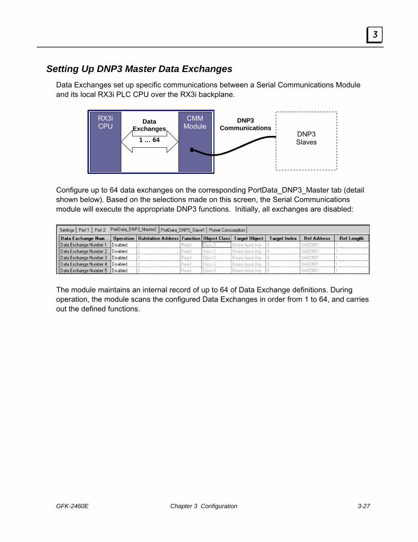
GFK-2460E Chapter 3 Configuration 3-27
3
Setting Up DNP3 Master Data Exchanges Data Exchanges set up specific communications between a Serial Communications Module and its local RX3i PLC CPU over the RX3i backplane.
RX3i CPU
CMM Module
Data Exchanges
1 … 64
DNP3 Communications
DNP3 Slaves
Configure up to 64 data exchanges on the corresponding PortData_DNP3_Master tab (detail shown below). Based on the selections made on this screen, the Serial Communications module will execute the appropriate DNP3 functions. Initially, all exchanges are disabled:
The module maintains an internal record of up to 64 of Data Exchange definitions. During operation, the module scans the configured Data Exchanges in order from 1 to 64, and carries out the defined functions.

3-28 PACSystems* RX3iSerial Communications Modules – June 2010 GFK-2460E
3
Data Exchange Parameters Define a Data Exchange for each unique DNP3 Master function the module should perform.
Operation
The Operation parameter sets up a Data Exchange between the Serial Communications Module and the RX3i PLC CPU. The default for each exchange is Disabled. Options are described below.
Select the appropriate Operation type for the type of DNP3 Master function to be performed. Note that some operations will require the configuration of multiple exchanges, as described on the next page.
Read Continuous: Select this type of Operation to set up a DNP3 Read (DNP3 Function 1) in which the DNP3 master port will repeatedly read the specified data from the target slave. The CPU does not control this exchange. The exchange only stops when PLC outputs are disabled (if the Outputs Disabled parameter on the Port tab is set to Stop Processing Exchanges).
Read Continuous Bit-Control: Select this type of Operation to set up a DNP3 Read (DNP3 Function 1) in which the DNP3 master port will repeatedly read the specified data from the target slave. The CPU starts or stops the operation by setting or clearing a bit in the port’s control output data (see chapter 4 for details).
Read Single Bit-Control: Select this type of Operation to set up a single DNP3 Read (DNP3 Function 1) in which the DNP3 master port will read the specified data from the target slave only when the CPU transitions the appropriate port control bit (see chapter 4 for details).
Write Continuous: Select this type of Operation to set up a DNP3 Write (DNP3 Function 2) in which the DNP3 master port will repeatedly read the the specified data from the assigned CPU references and then write the data to the slave’s Target Object and Target Index. The CPU does not control this exchange. The exchange only stops when PLC outputs are disabled (if the Outputs Disabled parameter on the Port tab is set to Stop Processing Exchanges).
Write Continuous Bit-Control: Select this type of Operation to set up either a DNP3 Write (DNP3 Function 2) or a Select operation (DNP3 Function 3) in which the DNP3 master port will begin writing to the slave when commanded by the CPU setting a bit in the port’s control output data (see chapter 4 for details). The master port will repeatedly write to the slave until commanded to stop by clearing the same bit.

GFK-2460E Chapter 3 Configuration 3-29
3
Write Single Bit-Control: Select this type of Operation to set up a single execution of any of the following DNP3 functions: Write (DNP3 Function 2), Select (DNP3 Function 3), Operate (DNP3 Function 4), Direct Operate w/wo Acknowledgement (DNP3 Function 5 or 6), Cold Restart (DNP3 Function 13), Enable or Disable Unsolicited Responses (DNP3 Function 20 or 21), or Assign Class (DNP3 Function 22). The master port will write to the slave once each time the CPU transitions the associated control bit (see chapter 4 for details).
Write Only: Select this type of exchange to set up CPU reference memory for Unsolicited Slave Response data. In addition, this type of exchange is to be used for slave responses to Any Variation Target Objects or 0 Ref Length (all points) DNP3 Master Read function issued.
For this DNP3 Master Function
Select this Exchange Operation
Read Continuous
Read Continuous Bit-Control
Read (DNP3 Function 1) Use this Function to read static or class data. See the Example Master Exchanges later in this section. Some reads will require configuring more than one exchange. Read Single Bit-Control
Write Continuous
Write Continuous Bit-Control Write (DNP3 Function 2)
Write Single Bit-Control
Write Continuous Bit-Control Select (DNP3 Function 3)
Write Single Bit-Control
Operate (DNP3 Function 4)
Direct Operate (DNP3 Function 5)
Direct Operate – No Acknowledgement (DNP3 Function 6)
Cold Restart (DNP3 Function 13)
Enable Unsolicited Responses (DNP3 Function 20)
Disable Unsolicited Responses (DNP3 Function 21)
Assign Class (DNP3 Function 22)
Delay Measurement (DNP3 Function 23)
Write Single Bit-Control
Slave Response (DNP3 Functions 129 and 130) Write Only
Outstation Address: Default is 0. The link address of the slave associated with the exchange. Range is 0 to 65535.

3-30 PACSystems* RX3iSerial Communications Modules – June 2010 GFK-2460E
3
Function: Select the type of DNP3 Function to be performed by the Data Exchange as listed above. As mentioned previously, the Functions that can be selected depend upon the previously-configured Operation type.
Read Read inputs, output status, time and date, class data, or internal indicators.
Write Write analog input deadband data, time and date, or internal indicators. Select Set up a Select before Operate write operation of discrete or analog output
data. In Select Before Operate mode, an output must first be selected by the master before operating on it. If the slave’s Select before Operate timeout expires, another Select Command must be issued to the data point before an Operate command will be honored.
Operate Execute a Select before Operate write operation of discrete or analog output data
Direct Operate with Acknowledge
Write discrete or analog output data to the slave, with acknowledgement.
Direct Operate no Acknowledge
Write discrete or analog output data to the slave, with no acknowledgement.
Cold Restart Issue a Cold Restart DNP3 Function to the slave. Enable Unsolicited Responses
Set up the slave to send unsolicited messages
Disable Unsolicited Responses
Set up the slave to disable sending unsolicited messages
Assign Class Assign binary or analog inputs to class 0, 1, 2, or 3. The data can then be read as a group using a Read command, The module uses the Reference Address and Length to tell the slave which points to assign to the class. If the Reference Length is 0, the module tells the slave to assign all of the data points for the given group the specified class.
Slave Response
Assign CPU memory addresses to binary or analog inputs or output status data that is received from the slave in response to a Read request with a data type of Any Variation or all points (Ref Length = 0), as well as unsolicited responses.

GFK-2460E Chapter 3 Configuration 3-31
3
Object Class: Object Class is an attribute of a data point or event object that the data point reports. The class attribute can be assigned to the change events that are generated when a significant variation in value is detected for the given static data point or any other notable event occurs. The change event is a historical record of a static data point's past value. It will have the same data point index as the associated static data point.
This configuration parameter is always Class 0 except when using a Write Single Bit-Control Data Exchange with the Function set to Assign Class. A class can be assigned to any binary or analog input. Assign classes 1, 2, and 3 to event data objects. Assign Class 0 only to data that formerly generated change events, but that should no longer generate change events.
During operation, a DNP3 master can read class 1, 2, or 3 change events that have been generated in relation to specific static data points. The slave devices themselves define what they will report back in a class 0 poll. If the slave is an RX3i Serial Communications Module DNP3 slave port, it will respond to a Class 0 poll with all of the defined points in their default variations for objects 1, 10, 30, and 40.
Target Object: The type of DNP3 data the master port will read or write using the Data Exchange. The configured Operation and DNP3 Function determine which of the Target Object Types listed on the next page are available.
Some DNP3 slaves do not support requests for specific data type variations. The DNP3 Master port can request a read from such slaves using one of the “… any variation” Target Objects. The slave will report back the value in its default variation. The reply includes an object header that defines its actual data format. The Serial Communications Module uses that information to convert the data into a format that can be written to CPU memory. Because the data format is not known until the module receives a reply from the DNP3 slave, the CPU Reference Address and Length cannot be set up in the same Data Exchange. For any read operation with a Target Object type of “… any variation”, a write-type Data Exchange must also be set up to define a Reference Address and Length for the data. The Reference Length specified in that exchange must accommodate all of the data from the external slave. Refer to the documentation for the external slave to help determine the correct size.

3-32 PACSystems* RX3iSerial Communications Modules – June 2010 GFK-2460E
3
Target Object Type DNP3 Object
DNP3 Variation
RX3i Data Type
Binary input any variation 1 0 Not known initially Binary input 1 1 Discrete input bits Binary input event any variation 2 0 Not known initially Binary output any variation 10 0 Not known initially Binary output status 10 2 Discrete output bits Analog input any variation 30 0 Not known initially 32-bit analog input 30 1 32-bit signed integer 16-bit analog input 30 2 16-bit signed integer 32-bit analog input w/o flag 30 3 32-bit signed integer 16-bit analog input w/o flag 30 4 16-bit signed integer Short floating point analog input 30 5 32-bit floating point analog input Long floating point analog input 30 6 64-bit floating point analog input Analog change event any variation 32 0 Not known initially Analog input deadband, any variation 34 0 Not known initially 16-bit analog input deadband 34 1 16-bit integer 32-bit analog input deadband 34 2 32-bit integer Short floating point analog input
deadband 34 3 32-bit floating point
Analog output status any variation 40 0 Not known initially 32-bit analog output status 40 1 32-bit integer analog output 16-bit analog output status 40 2 16-bit integer analog output Short floating point analog output status 40 3 32-bit floating point analog output Long floating point analog output status 40 4 64-bit floating point analog output Time and date 50 1 6-bytes. See chapter 8 for details Class 0 data 60 1 Class 1 data 60 2 Class 2 data 60 3 Class 3 data 60 4
Discrete input bits Analog inputs
Internal indicators 80 1 The slave’s IIN data. 16 bits. See chapter 8 for bit assignments. It is not necessary to write all 16 bits.
Control relay output block 12 1 Discrete output bits 32-bit analog output block 41 1 32-bit integer analog output 16-bit analog output block 41 2 16-bit integer analog output Short floating point analog output block 41 3 32-bit floating point analog output Long floating point analog output block 41 4 64-bit floating point analog output
Target Index: This is the offset (1 to 65535) within the slave’s Target Type memory for the data to be read/written.
Reference Address: The RX3i CPU memory type and starting address for the data to be read or written in the Data Exchange.
If the Target Object for the exchange is for one of the “… any variation” data types, no Reference Address or Length can be configured for the exchange because the format of the

GFK-2460E Chapter 3 Configuration 3-33
3
data is not known. A second Data Exchange must be configured to set up the CPU Reference Address and Length, as mentioned above.
For a Write Single Bit-Control with a Function of Assign Class, the module uses the Reference Address and Length to tell the slave which points to assign to the given class. If the Reference Length is 0, the module will tell the slave to assign all of the data points for the given group the specified class.
To select a memory type and starting address, double-click on the Ref Address field or right-click and select Data Entry Tool.
Select a
starting address
Select a memory type
Available references
Reference Length: the length of the memory area selected above in bits or 16-bit words (registers). Depending on the configured Target Object type, the Reference Length automatically shows the length of one Target Object. For example, if the configured Target Object type is Long Floating Point Analog Input, the Reference Length automatically changes to 4 (registers). The configuration software increments the Reference Length to be divisible by the size of the selected Target Object type.
An exchange that is configured with a reference length of 0 means that the master will issue a request to the Outstation for any or all points of the type defined by the Target Object parameter.

3-34 PACSystems* RX3iSerial Communications Modules – June 2010 GFK-2460E
3
Select then Operate on Slave Outputs Select then Operate requires two Data Exchanges to the same slave. Create a Write Single Bit-Control exchange to perform the Select function, and one or more additional Write Single Bit-Control exchange(s) to perform the Operate function:
When the CPU sets the appropriate bit in the port’s output control data, as defined in chapter 4, the Serial Communications Module DNP3 Master port sends a DNP3 Select function to the slave.
The Select operation remains active for the Select before Operate Timeout period specified on the Port configuration tab. Within this period, if the CPU sets the appropriate bit in the port’s output control data, the module sends the DNP3 Operate function to the slave.

GFK-2460E Chapter 3 Configuration 3-35
3
Configuring a Port for DNP3 Slave Protocol Machine Edition version 5.6 SIM 6 or later is required for DNP3 protocol configuration.
On the port tab, set Protocol to DNP3 Slave, then configure the additional port parameters as described below. Note that when a port on the module is configured for either DNP3 Slave or DNP3 Master, the other port(s) must either be configured for DNP3 or disabled.
Serial Port Settings Data Rate: Default: 19.2k. Choices are 1200, 2400, 4800, 9600, 19.2k, 38.4k, 57.6k, 115.2k baud. Choose a baud rate that matches that used by the DNP3 Master. Data bits: DNP3 protocol always uses eight data bits. Parity: None, Odd, Even. Default is Odd. Should match the other devices on the network. Stop Bits: Default is 1. Choices: 1, 2. DNP3 protocol uses eight data bits and one stop bit.

3-36 PACSystems* RX3iSerial Communications Modules – June 2010 GFK-2460E
3
Port Type: RS232, RS485 (2 wire), or RS485 (4 wire).
Flow Control: (for RS232 only) Default is none. Choices are None, or Hardware Control (RTS/CTS, RFR/CTS). If Hardware Control is specified, the port will assert RTS, then wait for CTS to become active before transmitting.
If CTS becomes active and then is de-asserted while the port is transmitting, up to 5 milliseconds may elapse before transmission stops. The maximum number of characters transmitted after CTS is de-asserted is proportional to the data rate. These values are in addition to the character that is being transmitted at the time CTS is de-asserted.
Flow Control Duplex: (for RS232 only) Default is Full Duplex. Choices are Full Duplex or Half Duplex.
Tx/RTS Drop Delay (bits), defaults to 0. Range 0 to 15 bit times. For RS485, or RS232 with Flow Control. This is the time from the end of the last transmitted character to the time when the transmitter is turned off (dropped). For RS232 with Hardware Flow Control enabled, this is the time from the end of the last transmitted character to the time when RTS is turned off.
Outputs Disabled Control: Default is Stop Processing Exchanges. Alternative is Continue Processing Exchanges. This option applies to continuous read and write exchanges. It does not apply to bit-controlled continuous exchanges or to single exchanges.
Port Config ID User Config ID: The Configuration ID used for the port. Default is 1. Range is 0 to 255.
Out Station Address: Default is 0. The link address of this slave. Range is 0 to 65519.
Application Response Timeout: Default is 10,000. Range is 0 to 65535. This is the length of time in milliseconds after which an abort will occur if the receipt of an application layer fragment is not responded to. This time should be longer than Link Confirmation Timeout multiplied by the Link Maximum Retry Count.
Select Before Operate Timeout: This parameter defines the maximum time in milliseconds after receiving a Select command from the master that the slave port will honor an Operate command from the master. Default is 5,000. Range is 0 to 65535mS. If the timeout expires, the slave port must receive another Select Command for the data point from the master before it will honor an Operate command.
Link Layer Confirmation: Determines when link layer fragments are sent with the Confirmation Required bit set. Default is Never. Choices are Always, Never, Sometimes. As the physical layer receives bytes, it passes them to the link layer. The link layer validates the error detection, removes the link header, and sends the received data frames to the transport layer. Only select Sometimes for multi-fragment responses of vital data.
Link Confirmation Timeout: If Link Layer Confirmation is set to Always or Sometimes, select a timeout period in milliseconds. Default is 2000. Range is 0 to 65535.This is the period after which a retry will occur if the link layer does not confirm receipt of a frame and the Link Maximum Retry Count has not been exceeded.

GFK-2460E Chapter 3 Configuration 3-37
3
Link Max Retry Count: If Link Layer Confirmation is set to Always or Sometimes, specify a maximum number of times the link layer will attempt to send the message at the link layer before passing a failure message to the application layer. Default is 3. Range is 0 to 255.
Periodic Sync Timeout Required: Default is False. If this is set to true and the Clock Valid Period has elapsed, IIN-4 (Need Time) will be set.
Clock Valid Period: If Period Sync Timeout Required is set to True, select the timeout period in minutes. Default is 30. Range is 1 to 3600. If this timeout expires, the slave must indicate that it needs Time Synchronization data from the Master.
Send Unsolicited Responses: Default is Disabled.
When this feature is enabled, the outstation can spontaneously transmit a response without first receiving a request for data. This feature provides the ability for the outstation to notify the Master as soon as possible after a change occurs. Use of this feature reduces communication traffic.
Note: This feature is supported in firmware versions 1.34 and later. If your Serial Communications module has an earlier firmware version, Send Unsolicited Responses must be set to Disabled. If a configuration with this feature enabled is downloaded to the earlier version, a System Configuration Mismatch fault will occur for the slot containing the communications module.
Unsolicited Response Destination Address: If Send Unsolicited Responses is Enabled, select the destination address of the Master device to which the unsolicited responses are to be sent. Default is 65519. Range is 0 to 65519.
Max Unsolicited Response Delay: If Send Unsolicited Responses is Enabled, select the amount of time that the transmission of an unsolicited response, containing all classes, 1, 2 and 3, of change events, will be delayed. The delay applies to each class that has been assigned separately.
For example, if Max Unsolicited Response Delay is set to 60,000 milliseconds, and one class 1 event is created and another change event of class 2 is created 30 seconds later, both will be transmitted in another 30 seconds. If a master requests a read of class 1 data within that last 30 seconds, the class 2 change event that is still buffered will be transmitted a full 1 minute and 30 seconds after the class 1 change event was created. When the class 1 change events are read, the timer for class 1 events is disabled, the class 2 Max Unsolicited Response Delay is still counting down and causes an unsolicited response to be transmitted when it expires.
Additionally, if a total of five change events of a single class are buffered, all currently buffered change events will be transmitted in an unsolicited response. If four class 1 change events have been created and two class 2 events exists as well, the creation of a fifth class 1 event will cause an unsolicited response to be transmitted that contains all of the class 1 and class 2 events, even if the class 1 or class 2 Max Unsolicited Response Delay has not expired.
After the outstation sends the unsolicited response message to the slave, a retry timer starts. The retry timer expires once the application timeout period has elapsed. At that point the retry

3-38 PACSystems* RX3iSerial Communications Modules – June 2010 GFK-2460E
3
timer is set to the retry delay time, after this expires, the unsolicited response message is sent again.
The Unsolicited Response Retry Delay controls when unsolicited responses can be transmitted. This parameter is used in conjunction with the application layer confirmation timeout: While waiting for confirmation of an unsolicited message, the outstation buffers and defers the response to these read function requests from the connected DNP Master. However, once the unsolicited message is confirmed, or once the confirmation timeout has expired, and once any buffered read request are responded to, it is possible for another unsolicited message to be immediately transmitted.
If the unsolicited message is not confirmed, it is not possible for another unsolicited message to be transmitted until the timer, as specified by the Unsolicited Response Retry Delay, expires.
This behavior allows the outstation (DNP3 slave) to respond to other commands in between unsolicited response retries.
Default is 5000ms. Range is 0 to 65535ms.
Unsolicited Response Retry Mode: If Send Unsolicited Responses is Enabled, specify the retry mode. Default is None. Choices are None, Limited or Indefinite.
If Limited is selected, the maximum number of retries is specified by Unsolicited Response Max Retry Count. If Indefinite is selected, the number of retries is unlimited.
Unsolicited Response Retry Delay: If Unsolicited Response Retry Mode is Limited or Indefinite, select the amount of time the outstation waits before resending an unacknowledged unsolicited response.
Default is 5000ms. Range is 0 to 65535ms.
Unsolicited Response Max Retry Count: If Unsolicited Response Retry Mode is Limited, specify the maximum number of times the outstation will attempt to send an unsolicited response if it does not receive an acknowledgement from the Master. Default is 3. Range is 0 to 255.
Analog Input Event Variation: Default setting is Variation 2 (16-bit w/o Time) When Variation 0 Requested. Select the format for sending analog input event data when variation 0 (“Any”) is requested. If variation 2 is selected, the Slave device sends the data as 16-bit integer with flag. If variation 4 is selected, the Slave device sends the data as 16-bit integer with flag and event time stamp.
Note: Only firmware versions 1.34 and later support variation 4 for reporting of analog input events. If your Serial Communications module has an earlier firmware version, the default setting (Variation 2) must be selected. If a configuration with Variation 4 selected is downloaded to an earlier version, a System Configuration Mismatch fault will occur for the slot containing the communications module.
Floating Point: Default is Disabled. Set to Enabled if the slave port will exchange floating point data with the DNP3 master.

GFK-2460E Chapter 3 Configuration 3-39
3
Setting Up DNP3 Slave Data Exchanges Data Exchanges set up specific communications between a Serial Communications Module and its local RX3i PLC CPU over the RX3i backplane.
RX3i CPU
CMM Module
Data Exchanges
1 … 64
DNP3 Master DNP3
Communications
Configure up to 64 data exchanges on the corresponding PortData_DNP3_Slave tab (detail shown below). Based on the selections made on this screen, the Serial Communications module will execute the appropriate DNP3 functions. Initially, all exchanges are disabled:
The module maintains an internal record of the Data Exchange definitions. When the module receives a DNP3 request from the Master, the module scans the Data Exchanges from 1 to 64. The module compares the request against the configured Data Exchanges until a match is found.
If a match is found, the requested exchange is carried out. The first match found while scanning from exchange 1 to 64 is always used. For PLC Access Types Read Only, Read / Write and Write Only, only one Data Exchange should be defined per DNP3 Object type (for example, Object 30, variation 1, 2, 5, or 6). The module will only execute the first configured exchange of that type. If additional exchanges of the same type are defined, they will be ignored by the module.
If no match is found, an error is returned to the requesting Master.

3-40 PACSystems* RX3iSerial Communications Modules – June 2010 GFK-2460E
3
Data Exchange Parameters Define a Data Exchange for each DNP3 Slave function the module should perform. Some functions require setting up more than one Data Exchange as described below.
PLC Access
The PLC Access parameter sets up each Data Exchange between the Serial Communications Module and the RX3i PLC CPU. The default for each exchange is Disabled. Options are described below.
Select the appropriate PLC Access type for the type of operation to be performed.
For this DNP3 Master Operation
Select this PLC Access Type for the DNP3 Slave Port
Read binary input, analog input , or binary status data from a range of PLC memory.
Read Only
Write static discrete or analog output data to a specified range of PLC memory.
Write Only
Read or write analog deadband values from a location in PLC memory.
Read / Write
Monitor a class of one or more data points in the RX3i PLC CPU for change events.
Create two (or more) Data Exchanges with these Access Types: 1. Read Only:
define the points to be monitored for change. 2. Write Single Bit-Control;
Write Continuous Bit-Control, or Write Continuous: set up the CPU’s reporting of some or all of the defined change events to the module.
3. (optional) If a deadband is required for determining change events, a Read/Write exchange should be defined with the Target Object being the type of analog input deadband needed. The application logic can use this value to determine whether a change event should be triggered.

GFK-2460E Chapter 3 Configuration 3-41
3
For each exchange that is enabled, specify the type of access the DNP3 Master will have. Choices are described below.
Write Continuous, Write Continuous Bit-Control, Write Single Bit-Control: On a Serial Communications Module DNP3 slave port, the write exchanges create change events. These change events will result in data being written to the external master's memory. The master has to poll for change events by issuing a read for class 1, 2 or 3 data to get these values "written" by the slave port.
Each Write Continuous, Write Continuous Bit-Control, or Write Single Bit-Control exchange defines a class of one or more data points within a range of static data points defined by a Read Only PLC exchange (see below) to be monitored for change events. The application logic in the PLC CPU is responsible for continually monitoring the data points defined by the Read Only exchange for change events. If a change event occurs, the application logic must report the change event data to the Reference Addresses assigned for the Write exchange. As configured in the Write exchange, the module reads this data from the PLC CPU and places change events in its internal event queue, where they are available to the DNP3 master. The change event queue has a maximum length of 25 change binary input events and 25 analog input events. On overflow, the least recent change event is discarded and the Buffer Overflow bit in the port’s IIN data is set. Any response to any master will include this IIN data, with the Buffer Overflow bit set.
a. Write Continuous: Starting at powerup, the module will continually read this data from the PLC CPU and place change events in its internal event queue, where they are available to the DNP3 master. The CPU has no control over this type of exchange.
b. Write Continuous Bit-Control: After receiving a command from the PLC CPU (using the port’s assigned control bits, as described in chapter 4), the module will continually read this data from the PLC CPU and place change events in its internal event queue, where they are available to the DNP3 master.
c. Write Single Bit-Control: After receiving a command from the PLC CPU (using the port’s assigned control bits, as described in chapter 4), the module will read this data once from the PLC CPU and place change events in its internal event queue, where they are available to the DNP3 master.
Read Only: Select this type of PLC Access to map static points that may be read by the DNP3 master. The CPU does not control this exchange. Use this type of exchange to allow the DNP3 Master to read all data within a specified range. There is no indication of change status in this static data.
Also select Read Only PLC Access as the first step in setting up change event reporting for a group of data.
Read /Write: Select this type of PLC Access to set up reading / writing 16-bit or 32-bit analog input deadband values by the DNP3 Master. The application logic in the RX3i PLC determines when to create change events for individual data points. A deadband can be used to avoid reporting of minor fluctuations in the input values as events. The Target Index for each Analog Input Deadband should be the same as the Target Index specified

3-42 PACSystems* RX3iSerial Communications Modules – June 2010 GFK-2460E
3
for the corresponding analog input point. To report the change events to the Serial Communications module, configure a Write Continuous, Write Continuous Bit-Control, or Write Single Bit-Control exchange as described above.
Write Only: Select this type of PLC Access to allow an external DNP3 master to write discrete or analog output data to the assigned CPU reference addresses.
The status of the outputs can be read back using Read Only exchanges with their Target Object type (see next page) set to the appropriate output status data type. The output status data types can be the commanded values or the current values of the output. By configuring the same reference addresses for both, the commanded value can be obtained.
Object Class: Default is No Change, which specifies Class 0 data (Read Only, returns all static points). If the PLC Access type for the exchange is Write Continuous, Write Continuous Bit-Control, or Write Single Bit-Control, the Object Class can remain No Change or be set to Class 1, Class 2, or Class 3. The Object Class on these exchanges defines the default class assignment at powerup or after a cold restart of the slave port. If the Object Class is set to No Change, the module will not start creating change objects for the points associated with that exhange until the DNP3 master assigns a class to the points.
An external DNP3 master can change these classes by sending an Assign Class function to the port. The master can disable change events by assigning the data points to Class 0 (static data).
Target Object: Selections depend on the PLC Access Type, as listed below. The exchange should include all of the data points of that Target Object type that might be required by the DNP3 Master. The master can access any point or set of points defined for the exchange. If the DNP3 Master requests an operation on a data point that is not present in the first configured exchange of the appropriate type, the module will reply that the point does not exist.
Note that in DNP3, data is expected to begin at offset 0 and data points are expected to be contiguous. The application logic in the PLC CPU may need to manipulate PLC data to accommodate this DNP3 requirement.
For PLC Access types Write Continuous, Write Continuous Bit-Control, and Write Single Bit-Control, multiple Data Exchanges can be set up for the same Target Object type, as Iisted in the table below.
For PLC Access Types Read Only, Read / Write and Write Only, only one Data Exchange should be defined per DNP3 Object type (for example, Object 30, variation 1, 2, 5, or 6). The module will only execute the first configured exchange of that type. If additional exchanges of the same type are defined, they will be ignored by the module.

GFK-2460E Chapter 3 Configuration 3-43
3
PLC Access Types Target Object (DNP3 Object and Variation Numbers shown for reference)
Write Continuous, Write Continuous Bit-Control, Write Single Bit-Control
Binary Input (Object 1,variation 1) 32-Bit Analog Input (Object 30, variation 1) 16-Bit Analog Input (Object 30, variation 2) Short Floating Point Analog Input * (Object 30, variation 5) Long Floating Point Analog Input * (Object 30, variation 6)
Binary Input (Object 1,variation 1) Binary Output Status (Object 10,variation 2) 32-Bit Analog Input Without Flag (Object 30, variation 3) 16-Bit Analog Input Without Flag (Object 30, variation 4) Short Floating Point Analog Input * (Object 30, variation 5) Long Floating Point Analog Input * (Object 30, variation 6)
Read Only For each Target Object type (for example Object 30, variation 3, 4, 5, or ) at right, only one Read Only exchange should be defined. 32-Bit Analog Output Status (Object 40, variation 1)
16-Bit Analog Output Status (Object 40, variation 2) Short Floating Point Analog Output Status* (Object 40, variation 3) Long Floating Point Analog Output Status* (Object 40, variation 4)
Read / Write Only one exchange should be defined.
16-Bit Analog Input Deadband (Object 34, variation 1)) 32-Bit Analog Input Deadband (Object 34, variation 2) Short Floating Point Analog Input Deadband * (Object 34, variation 3)
Control Relay Block (Object 12, variation 1) Write Only For each Target Object type at right, only one Write Only exchange should be defined.
32-Bit Analog Output Block (Object 41, variation 1) 16-Bit Analog Output Block (Object 41, variation 2) Short Floating Point Anaog Output Block * (Object 41, variation 3) Long Floating Point Analog Output Block * Object 41, variation 4)
* if enabled
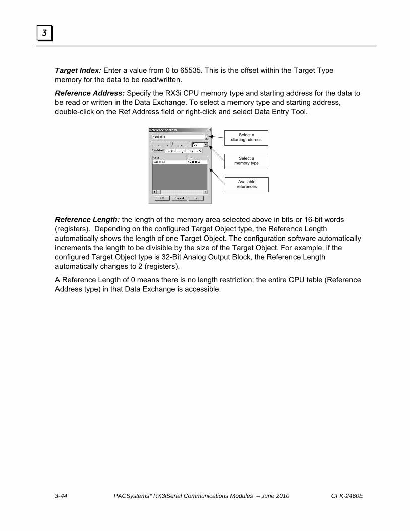
3-44 PACSystems* RX3iSerial Communications Modules – June 2010 GFK-2460E
3
Target Index: Enter a value from 0 to 65535. This is the offset within the Target Type memory for the data to be read/written.
Reference Address: Specify the RX3i CPU memory type and starting address for the data to be read or written in the Data Exchange. To select a memory type and starting address, double-click on the Ref Address field or right-click and select Data Entry Tool.
Select a
starting address
Select a memory type
Available references
Reference Length: the length of the memory area selected above in bits or 16-bit words (registers). Depending on the configured Target Object type, the Reference Length automatically shows the length of one Target Object. The configuration software automatically increments the length to be divisible by the size of the Target Object. For example, if the configured Target Object type is 32-Bit Analog Output Block, the Reference Length automatically changes to 2 (registers).
A Reference Length of 0 means there is no length restriction; the entire CPU table (Reference Address type) in that Data Exchange is accessible.

GFK-2460E Chapter 3 Configuration 3-45
3
Configuring a Port for Serial Protocol Language (SPL) Machine Edition version 5.8 SIM 2 or later is required for SPL protocol configuration.
On the port tab, set Protocol to SPL, configure the additional port parameters described below. (If a port’s protocol is set to disabled, and that port has been set up to serve as the Command Line Interface (CLI) port for another port on the module, its communications parameters are fixed at 9600 baud, 8 bits, no parity, and 1 stop bit).
Serial Port Settings Data Rate: Default: 19.2k. Choices are 1200, 2400, 4800, 9600, 19.2k, 38.4k, 57.6k, 115.2k baud. Data bits:. Choices 7, 8. Parity: None, Odd, Even. Default is Odd. Stop Bits: Default is 1. Choices: 1, 2. Port Type: RS232, RS485 (2 wire), or RS485 (4 wire).
Flow Control: (for RS232 only) Default is none. Choices are None, or Hardware Control (RTS/CTS). If Hardware Control is specified, the port will assert RTS, then wait for CTS to become active before transmitting.
Flow Control Duplex: (for RS232 only). Default is Full Duplex. Choices are Full Duplex or Half Duplex. Tx/RTS Drop Delay (bits), defaults to 0. Range 0 to 15 bit times. For RS485, or RS232 with Flow Control. This is the time that will be used by the module to calculate the time (in bit-times) to wait before dropping RTS.

3-46 PACSystems* RX3iSerial Communications Modules – June 2010 GFK-2460E
3
SPL Port Settings CLI Port: This defaults to disabled. If selected, it displays a list of all ports that currently have their protocol set to disabled. To use a Command Line Interface port, it is recommended that at least one port be left disabled in the configuration (rather than disabling a port for use with the Command Line Interface after previously configuring it for another purpose).
Typically, the assignment of a port for use with the Command Line Interface is temporary. After the SPL script is debugged, the Command Line Interface can be reassigned for use by any module protocol except DNP3, or set to disabled (for example, to allow the same port to subsequently be selected as the Command Line Interface port for another SPL port on the module).
Auto Run Program: If Command Line Interface is set to Enabled, choose whether or not the SPL script on the port will start running automatically. If this is set to disabled, the SPL script in the module must be started/controlled using the Command Line Interface Run command.
Port Config ID User Config ID: The Configuration ID used for the port. Default is 1. Range is 0 to 255.

GFK-2460E Chapter 3 Configuration 3-47
3
Setting Up SPL Data Exchanges Data Exchanges allow the Serial Communications Module to read or write controller data over the RX3i backplane.
RX3i CPU
CMM Module
Data Exchanges
1 … 64
External Device Communications
Protocol
Configure up to 64 data exchanges on the corresponding PortData tab (detail shown below). Initially, all exchanges are disabled:
The module maintains an internal record of the Data Exchange definitions. When the module encounters an appropriate command in the SPL script, or an appropriate command from the Command Line Interface port, it executes the requested CPU read or write.
Data Exchange Parameters
Exchange Type Controlled: Select Controlled if the execution of the exchange will be triggered by an EXNEXT statement and monitored by an EXSTAT statement in the SPL script. Controlled exchanges provide the RX3i PLC CPU with master-like control of the port’s reads and writes.
Validated: Select Validated if execution of the exchange will be triggered by a EXREAD or EXWRITE statement in the SPL script. Validated exchanges allow the module to read or write the associated areas of CPU memory without action by the application logic.
Print Exchange: Select Print Exchange if the output of a PRINT command should be sent to this exchange’s Reference Address. When Exchange Type is set to Print Exchange, the other exchange parameters are automatically set to: Operation: Write Only, Target ID: 0, Target Type: 255, Target Address: 0, Ref Length = 128 Words (or 2048 bits). There may only be one print exchange for the port.
Disabled: the exchange number is not defined.

3-48 PACSystems* RX3iSerial Communications Modules – June 2010 GFK-2460E
3
Operation The Operation parameter sets up each Data Exchange between the Serial Communications Module and the RX3i PLC CPU.
If the Exchange Type (previous page) is set to Controlled, the Operation can be Read Continuous, Read Continuous Bit-Control, Read Single Bit-Control, Write Continuous, Write Continuous Bit-Control, or Write Single Bit-Control. These exchanges are used by EXNEXT commands in the SPL script.
1. Read Continuous: This type of exchange repeatedly reads the specified data from the module and places it into the assigned CPU reference addresses. The CPU does not control the execution of exchange. Execution stops only when PLC outputs are disabled.
2. Read Continuous Bit-Control: This type of exchange must be started by setting a bit in the CPU (see chapter 4 for details). The CPU then periodically reads the specified data from the module until commanded to stop by clearing the same bit.
3. Read Single Bit-Control: This type of exchange must be initiated by setting a bit in the CPU (see chapter 4 for details). The CPU reads the specified data once each time the control bit transitions.
4. Write Continuous: This type of exchange repeatedly writes the specified bit or word data from the assigned CPU references to the module. The CPU does not control the execution of exchange. Execution stops only when PLC outputs are disabled (if the Outputs Disabled parameter on the Port tab is set to disable continuous exchanges when outputs are disabled.
5. Write Continuous Bit-Control: This type of exchange must be started by setting a bit in the CPU (see chapter 4 for details). The module then periodically writes the specified data to the slave until commanded to stop by clearing the same bit.
6. Write Single Bit-Control: This type of exchange must be initiated by setting a bit in the CPU (see chapter 4 for details). The module writes the specified data once each time the control bit transitions.
If the Exchange Type (above) is set to Validated, the Operation can be Read Only, Read/Write, or Write only. These exchanges are used by EXREAD and EXWRITE commands in the SPL script. For each EXREAD and EXWRITE command, the EXCHANGE global variable will specify the Exchange ID, type, buffer, offset, and length.

GFK-2460E Chapter 3 Configuration 3-49
3
Read Only: Select this type of Operation to set up an area of CPU memory to be read by the module when it encounters an EXREAD command in the SPL script.
Read /Write: Select this type of Operation to set up an area of CPU memory that will be available for access by either EXREAD or EXWRITE in the SPL script.
Write Only: Select this type of Operation to set up an area of CPU memory to be written by the module when it encounters an EXWRITE command in the SPL script.
Target ID: A value from 0-255. This represents the communications ID of the external device on its LAN.
Target Type: A value from 0-254. These numbers can be assigned functions by the SPL script. For example, the Target Type 27 might be used to represent MODBUS coil data. The SPL script would then make the translation between this generic number and the actual protocol data type it represents. Using generic Target Type data makes it possible to exchange any type of data.
Target Type 255 is reserved for the Print Exchange. When the Target Type is set to 255, PRINT statement output will be sent to this exchange’s defined Reference Address (below). There may only be one print exchange per port.
Target Address: A value from 0-65535. Only allowed for Controlled exchanges. When Target Type (above) is set to 255 (Print), the Target Address is automatically set to 0.
Reference Address: Specify the RX3i CPU memory type and starting address for the data to be read or written in the Data Exchange. To select a memory type and starting address, double-click on the Ref Address field or right-click and select Data Entry Tool.
Reference Length: Length: 0 to 512 words for validated Exchange Type, 1 to 512 words for controlled Exchange Type, 128 words or 2048 bits for a Print Exchange. 0 indicates all of the reference memory specified by the Ref Address. When Target Type is set to 255 (print), Reference Length is automatically set to 128 words (2048 bits).

3-50 PACSystems* RX3iSerial Communications Modules – June 2010 GFK-2460E
3
Attaching and Downloading the SPL Script To attach an SPL script to the Target containing the Serial Communications Module, the SPL script must be accessible in the computer’s file system.
With the module configured as described previously and one or more ports set to SPL, click on the module in the Navigator window.
In the Inspector window, scroll down to “File for Port”.
Click in the right-hand box, then click on the select button.

GFK-2460E Chapter 3 Configuration 3-51
3
In the File for Port dialog box, navigate to the location of the SPL file:
Select the file to attach (one per port), and click open.
The script is now attached to the Target.
Viewing the SPL Script Attached to a Target In Navigator, scroll down to “Supplemental files > AUP files”:
Double-click on “AUP Files” to display all SPL files associated with the Target. In the example below, three ports have been configured for SPL protocol, and an SPL file has been attached for each of the three ports:

3-52 PACSystems* RX3iSerial Communications Modules – June 2010 GFK-2460E
3
Editing an SPL Script To edit an SPL file that is already attached to a Target, double-click on the file in the AUP Files window shown on the previous page. In the Open With window, select Notepad or a similar text editor to open the file. An example file is shown below.
If you edit an SPL file that is already attached, it does not need to be re-attached to the Target. If you edit an SPL file in its original location, the new version must be re-attached to the Target.
Caution
If multiple SPL ports are set up to use the same SPL filename, any changes to the file with that name will be sent to every port that uses it, when the hardware configuration is downloaded. If that operation is not appropriate for the application, make sure that different SPL filenames are used.
SPL Validation Errors Each port on a Serial Communications Module that is configured for SPL protocol must have an SPL file attached as described above. The following errors may occur when the target is Validated:
12249 SPL file is present but larger than 32k bytes 12250 No file configured, or missing from AUP file directory.
If an error occurs, double-click on the error to jump to the error location in the Inspector window.
GFK-2460E 4-1
Port Status and Control Data
This chapter describes status, control, diagnostics, and communications data for PACSystems RX3i Serial Communications modules. It also explains how the DO I/O and Suspend I/O functions can be used with these modules.
Transfer of Status and Control Data
Port Status Input Data
Port Control Output Data
Error Status Handling
Using DO I/O and Suspend I/O
Module Status and Control data does not include the serial communications data that is exchanged between the module and one or more serial devices. That data uses a different set of assigned CPU references, and is written to or read from the CPU outside of the CPU’s normal I/O Scan.
Because each protocol handles serial communications data differently, serial communications data is covered in the chapters of this manual that describe the individual port protocols.
Chapter
4

4-2 PACSystems* RX3iSerial Communications Modules – June 2010 GFK-2460E
4
Transfer of Status and Control Data Module configuration reserves CPU memory for the module’s Port Status and Control data. Each port’s status and control data references are configured separately; lengths are fixed.
Data Type Total Data Length Memory Type Port Status Data 224 bits per port
CMM002: 448 bits CMM004: 896 bits
%I, %M, %T, or discrete I/O variables
Port Control Data 128 bits per port
CMM002: 256 bits CMM004: 512 bits
%Q, %M, %T, or discrete I/O variables
During system operation, Port Status and Port Control data is transferred between the RX3i CPU and a Serial Communications module during the CPU’s I/O Scan.
CPU Sweep
Read Inputs
Execute Application Program
Write Outputs
CPU
Port Status Data
Serial Communications Module
Port Control Data
IC695CMM004
MODULE OK
PORT FAULT
P1P2:P3:P4:
STATUS
PORT 1
STATUS
PORT 2
STATUS
PORT 3
STATUS
PORT 4
If the CPU is stopped with outputs disabled, it stops exchanging Port Status and Control data with the module. When the CPU goes back into Run mode, it resumes reading Port Status data and module status information.
The application should monitor the Port Status input data for information about serial communications status, and use the Port Control output data to send the module commands, acknowledge faults, or reset a port.
In addition to being transferred during the I/O Scan, transfer of status and control data can be controlled using the DO I/O and Suspend I/O program functions as described in this chapter.

GFK-2460E Chapter 4 Port Status and Control Data 4-3
4
Port Status Input Data The Port Status input data format for each port is shown below. The byte and bit values used in the table represent relative offsets from the start of each port’s status data.
Bytes Bits Description Exchange Response Report (module sets all bits to 0 on startup)
MODBUS Master, DNP3 Master
One bit per exchange: bit 1 = exchange 1 to bit 64 = exchange 64 For continuous exchanges: Last exchange completed successfully. For single bit-control exchanges: Last exchange completed
successfully when this matches the corresponding control bit. DNP3 Master only:
Write only exchanges: Last exchange completed successfully.
MODBUS Slave
One bit per exchange: bit 1 = exchange 1 to bit 64 = exchange 64 0 = Last Exchange Execution Failed or has yet to be executed 1 = Last exchange execution completed successfully
Serial I/O
Bit 1 indicates a new Serial I/O receive has completed when this bit matches the corresponding control bit Bit 2 indicates a new Serial I/O transmit has completed when this bit matches the corresponding control bit Bits 3–64 are reserved
CCM Slave, DNP3 Slave
One bit per exchange: bit 1 = exchange 1 to bit 64 = exchange 64 If PLC Access is configured as Read Only, Read/Write, or Write Only:
0 = Last Exchange Execution Failed or has yet to be executed 1 = Last exchange execution completed successfully
DNP3 Slave Only: If PLC Access Type is Write Continuous: not used If PLC Access Type is Write Continuous Bit-Control: Last exchange
completed successfully. If PLC Access Type is Write Single Bit-Control: Last exchange
completed successfully when this matches the corresponding control bit.
If PLC Access is configured as any other type: For continuous exchanges: Last exchange completed successfully For single bit-control exchanges: Last exchange completed
successfully when this matches the corresponding control bit
1 - 8 1 - 64
SPL
One bit per exchange: bit 1 = exchange 1 to bit 64 = exchange 64 If Exchange Type is configured as Controlled,
For continuous exchanges: Last exchange completed successfully. For single bit-control exchanges: Last exchange completed
successfully when this matches the corresponding control bit. If Exchange Type is configured as Validated:
0 = Last Exchange Execution Failed or has yet to be executed 1 = Last exchange execution completed successfully

4-4 PACSystems* RX3iSerial Communications Modules – June 2010 GFK-2460E
4
Bytes Bits Description Exchange Error Report MODBUS CCM Slave DNP3 SPL
One bit per exchange: bit 65 = exchange 1 to bit 128 = exchange 64 0 = no error detected 1 = error detected. This bit remains 1 until errors are acknowledged.
9 - 16 65 - 128
Serial I/O Bit 65 = 1 indicates a receive error has occurred Bit 66 = 1 indicates a transmit error has occurred Bits 67 – 128: Reserved
Port Status Bit 129 Port Ready = 1 Bit 130 Configuration underway = 1 Bit 131 1 = Control Bit Ready. The Exchange Control bit is being used for bit-
controlled operations. Set to 0 if outputs are disabled. 132 – 136 Reserved
17 - 18
129 - 144
137 – 144 (Byte 18) Configuration ID from the Port configuration tab Protocol Status MODBUS Master / Slave: this data not used. Serial I/O Bit 145: CTS Status for RS232 when HW Control Disabled: 0 = Not CTS,
1 = CTS Bits 146 – 160: Spare Bits 161 – 176 (Word): Number of input buffer characters (bytes) availableBits 177 – 192 (Word): Number of characters(bytes) received
CCM Slave Not used Bits 145 – 160: Reserved. Bits 161 – 176: If bits 201 – 208 contain the value 20, (14h), this word contains the slave’s IIN bits. Otherwise, this data is not applicable. 161 All stations; broadcast
message received 169 Function code not supported
162 Class 1 events available 170 Object unknown 163 Class 2 events available 171 Parameter error 164 Class 3 events available 172 Event buffer overflow 165 Need time: write time and
date to slave 173 Already executing requested
operation 166 Local control 174 Configuration corrupt 167 Device trouble 176 Reserved, always 0 168 Device restart 176 Reserved, always 0
DNP3 Master
Bits 177 – 192: Spare. DNP3 Slave Not used
19 - 24
145 – 192
SPL Byte 19 (Bits 145 – 152): SPL Port Status.

GFK-2460E Chapter 4 Port Status and Control Data 4-5
4
Bytes Bits Description 20 = invalid syntax 21 = invalid argument 22 = invalid operator 23 = invalid expression 24 = invalid tag reference 25 = invalid reference index 26 = unknown identifier 27 = identifier previously defined 28 = range of variable exceeded 29 = missing quote in string or character declaration 30 = missing argument 31 = divide by zero error 32 = end of file unexpectedly encountered 33 = internal interpreter error 34 = search error line of label not found35 = maximum concatenation arguments exceeded 36 = maximum nesting limit exceeded 37 = maximum variable declarations exceeded
38 = internal stack failure 39 = calculation > 2,147,483,647 or < -2,147,483,648 40 = expression result < 0 or > 255 41 = internal exchange error 42 = EXSTAT must be executed for the previous EXNEXT 43 = EXNEXT must be executed prior to EXSTAT 44 = EXCHANGE.buffer must be assigned prior to command 45 = label found in nested statement 46 = control statement found without match 47 = missing assignment of value to a variable 48 = assignment to read only variable 49 = maximum label limit exceeded 50 = Program download failed 51 = No program loaded 53 = Program loaded but stopped
Bytes 20 – 25: IOSTAT available in SPL program Error Status Exchange Number MODBUS, CCM Slave, DNP3, SPL
Master / Slave: Exchange number of the error in the Error Status field (below)
25 193- 200
Serial I/O Value of 1 = receive error; 2 = transmit error

4-6 PACSystems* RX3iSerial Communications Modules – June 2010 GFK-2460E
4
Bytes Bits Description Error Status General Errors
0 = no error 1 = generic port error or module error 2 = receive overflow 3 = parity error 4 = framing error 5 = receive timeout
6 = transmit timeout 7 = module failed to send to CPU 8 = sent to CPU, but failure response 9 = not able to send to CPU, module timed out
MODBUS 20 = unrecognized exception 21 = illegal function 22 = illegal data address 23 = illegal data value 24 = slave device failure 25 = acknowledge 26 = slave device busy 27 = negative acknowledge 28 = memory parity error
29 through 35 reserved 36 = CRC error on response 37 = unexpected slave address 38 = unexpected function code 39 =unexpected response length 40 = exchange register type is bad 41 = exchange register address is bad 42 =returned query data does not match
Serial I/O 20 = data requested exceeds assigned memory 21 = bad checksum. Message discarded
22 = Data buffer overflow. New data discarded until characters have been removed from the buffer 23 = transmit command cancelled 24 = receive command cancelled 25 = data size exceeds 2k limit
CCM Slave No additional error codes defined. DNP3 Master 20 = Slave IIN bits. Bit values are in DNP3 Master Protocol Status (above)
21 = No Data (Valid for Class Read Requests) DNP3 Slave 20 = Invalid function code received.
26 201 – 208
SPL Defined by SPL script . Should start at 20. Period Time 27 -
28 209 – 224 The time to execute all Master exchanges, in milliseconds. 0 for slave protocols, 0 –
65535 for master protocols. Exchange times above 65535mS appear as 65535mS.

GFK-2460E Chapter 4 Port Status and Control Data 4-7
4
Input Data Definitions
Exchange Response Report, Input Bits 1-64 (Bytes 1-8) The Exchange Response Report bits reflect the execution status of the configured communications.
MODBUS Master, DNP3 Master:
For Read or Write Continuous exchanges, if this bit is 1, the last execution of the exchange completed successfully. If this bit is 0, the last attempt has either failed or not yet completed.
For Read or Write Continuous Bit-Controlled exchanges, if this bit is 1, the last exchange attempt completed successfully. If this bit is 0, the last attempt has either failed or not yet completed, or the control bit was set to 0 during the last output scan, causing no exchange to be attempted.
For a read or write single (one-shot) exchange, if this bit matches the corresponding Exchange Control output bit in the output status data, the exchange has completed successfully. If this bit does not match the output data, the exchange is still pending. When the bit changes to match the commanded state, the exchange is complete.
For a DNP3 Write Only exchange, if this bit is 1, the last execution of the exchange completed successfully. If this bit is 0, the last attempt has either failed or not yet completed.
MODBUS Slave: If this bit is 0, the exchange failed or has not yet executed. If this bit is 1, the last execution of the exchange completed successfully.
Serial I/O: only the first two Exchange Response bits are used. If bit 1 matches the corresponding Control bit, a new Serial I/O receive has completed. If this bit does not match the output data, the receive is still pending. When the bit changes to match the commanded state, the receive is complete. If bit 2 matches the corresponding Control bit, a new Serial I/O transmit has completed. If this bit does not match the output data, the transmit is still pending. When the bit changes to match the commanded state, the transmit is complete.
CCM Slave, DNP3 Slave:
For PLC Access of Read Only , Read/Write or Write Only, if this bit is 1, the last exchange attempt completed successfully. If this bit is 0, the last attempt has either failed or not yet completed, or the control bit was set to 0 during the last output scan, causing no exchange to be attempted.
DNP3 Only: for a Write Continuous, not used.

4-8 PACSystems* RX3iSerial Communications Modules – June 2010 GFK-2460E
4
DNP3 Only: Write Continuous Bit-Control or Write Single Bit-Control, if this bit is 1, the last exchange attempt completed successfully. If this bit is 0, the last attempt has either failed or not yet completed, or the control bit was set to 0 during the last output scan, causing no exchange to be attempted.
For all other types of PLC Access, if this bit is 1, the last execution of the exchange completed successfully. If this bit is 0, the last attempt has either failed or not yet completed.
SPL
If Operation Type is Controlled, for Read or Write Continuous exchanges, if this bit is 1, the last execution of the exchange completed successfully. If this bit is 0, the last attempt has either failed or not yet completed.
If Operation Type is Controlled, for Read or Write Continuous Bit-Controlled exchanges, if this bit is 1, the last exchange attempt completed successfully. If this bit is 0, the last attempt has either failed or not yet completed, or the control bit was set to 0 during the last output scan, causing no exchange to be attempted.
If Operation Type is Validated, if this bit matches the corresponding Exchange Control output bit in the output status data, the exchange has completed successfully. If this bit does not match the output data, the exchange is still pending. When the bit changes to match the commanded state, the exchange is complete.
Exchange Error Report, Input Bits 65-128 (Bytes 9-16) The Exchange Error Report input bits reflect the error status of the configured communications.
For DNP3 and MODBUS Master or Slave,CCM Slave, and SPL: the 64 Exchange Error Report bits report the error status of the configured exchanges. For each exchange, if the corresponding bit is = 1, an error occurred for that exchange. The bit remains set until one of the following occurs:
The error is acknowledged by the application setting the Port Error Exchange Selector to the exchange number (Port Control bits 73-80) and the Port Command bit 65 to 1.
All errors are cleared by the application setting Port Command bit 66. The port is reset by the application setting Port Command bit 67. The module receives a new configuration.
For Serial I/O: only the first two Exchange Error Report bits are used. If bit 65 = 1. a Serial I/O receive error has occurred. If bit 66 = 1, a transmit error has occurred.

GFK-2460E Chapter 4 Port Status and Control Data 4-9
4
Port Status, Input Bits 129-144 (Bytes 17, 18) These two bytes provide information about the status of the port for all protocols.
Bit 129 indicates whether or not the port is ready for communications Bit 130 indicates whether or not the port is currently being configured Bit 131 indicates whether or not the exchange Control bits are ready to control
exchanges. Bits 132 to 136 are reserved. Byte 18 (bits 137 – 144) contains the Configuration ID that was configured for the
port. If the application includes multiple configurations, this bit can be used to check which configuration is being used for the port.
Protocol Status, Input Bits 145-192 (Bytes 19 – 24) Not used for MODBUS or CCM.
For Serial I/O, these bits provide the following information.
CTS Status, Bit 145 is used for RS-232 communication, when the port’s Flow Control parameter has been configured for Hardware Control (RTS/CTS). Before transmitting, the CPU should set output bit 84 (Activate RTS) in the port’s Port Control Data to 1 to force RTS on the port. The CPU should then check input bit 145 (CTS active). When this bit is 1, the port can safely transmit. If CTS does not become active within 2 seconds, the module returns a timeout error to the status location.
After the last transmit character is sent, the CPU must set the RTS bit to 0. If CTS becomes active and then is de-asserted while the port is transmitting, up to 5 milliseconds may elapse before transmission stops. The maximum number of bytes transmitted after CTS is de-asserted is proportional to the data rate. These values are in addition to the byte that is being transmitted at the time CTS is de-asserted.
Data Rate Maximum Number of Characters Received after CTS is De-asserted
Data Rate Maximum Number of Characters Received after CTS is De-asserted
1200 2400 4800 9600
1 2 3 5
19200 38400 57600
115200
10 20 29 58
Bits 161 to 176, ”number of input buffer characters available” is a data word containing the number of input buffer bytes available in the module to receive data from the serial device. If there are no characters in the port’s input buffer, the module ends the receive operation immediately. The module then sets the port’s Exchange Error Report bit to 1 and the “received character count” (next item) to 0. The CPU is responsible for reading serial data out of the buffer to make room for new data.
Bits 177 to 192, “number of characters received” is a word of data that contains the number of bytes received by the module.

4-10 PACSystems* RX3iSerial Communications Modules – June 2010 GFK-2460E
4
For DNP3 Master, these bits provide the following information.
Bits 145 to 160 and 177 to 192 are reserved or spare. Bits 161 through 176 are only meaningful if the value in bits 201 to 208 is 20 decimal (14 hex). In that case, these bits are the DNP3 IIN bits of the slave that responded to the exchange. These bits are discussed in more detail in chapter 8.
For Serial Protocol Language (SPL):
Byte 19 contains the SPL Port Status. The value in byte 19 is the protocol status of the port.
Bytes 20 to 24 can be used by the program variable IOSTAT. The content of this data depends on the application. The application logic in the controller can monitor these bytes for changes that have been made by the SPL script. The SPL script can use this data to pass information to the CPU about errors or protocol conditions. See chapter 9 for more information.
Error Status Exchange Number, Input Bits 193 – 200 (Byte 25)
For SPL, MODBUS and DNP3 Master or Slave: When an error occurs on a port, this byte identifies the exchange number that had the error. If the Error Exchange Number Selector (output bits 73-80) is 0, this byte contains the last processed exchange number, whether or not that exchange had an error. To retrieve the error status of a specific exchange, the CPU must send the module its exchange number in the Port Control output data.
For Serial I/O: A value of 1 in this byte indicates a receive error, and a value of 2 indicates a transmit error.
Error Status, Input Bits 201 – 208 (Byte 26) When an error occurs on a port, this byte contains a number representing the error type (for example, 2 = receive overflow). See the previous table for a list of error numbers. If the Error Exchange Number Selector (output bits 73-80) is 0, this byte contains the error status of the last processed exchange, whether or not that exchange had an error. To retrieve the error status of a specific exchange, the CPU must send the module its exchange number in the Port Control output data.
Period Time, Input Bits 209 – 224 (Bytes 27, 28) For MODBUS Master, these two bytes contain the time required to execute all master exchanges, in milliseconds. Each time all exchanges have been scanned (either processed or passed over) this value is updated, indicating the time it took for the Exchange scan to complete.
For MODBUS Slave and Serial I/O, these bytes are reserved.

GFK-2460E Chapter 4 Port Status and Control Data 4-11
4
Port Control Output Data The Port Control output data for each port is shown below. The byte and bit values used in the table represent relative offsets from the start of each port’s control data.
Byte Bit Description Exchange Control Bits MODBUS Master, DNP3 Master, SPL
One bit per exchange. Used if the Operation type is one of the Bit-Control choices (such as Read Single, Bit-Control).
Serial I/O Bit 1 = Receive Packet Bit 2 – Transmit Packet
1 - 8 1 - 64
CCM Slave One bit per exchange. Used if the PLC Access type is one of the Bit-Control choices (such as Read Single, Bit-Control). Not used for other PLC Access types.
Port Command 9
65 - 72 Bit 65: 1 = Acknowledge the error indicated in the Error Status and Error
Status Exchange Number input data fields. Bit 66: 1 = Clear All Errors Bit 67: 1 = Port Reset Bits 68 - 72: spare Port Exchange Error Selector 10 73 – 80
(byte) Specifies the Exchange Number for which the Error Status and Error Status Exchange Number will be returned by the module in the input data. Output Commands to the Module MODBUS Master / Slave: this data not used. Serial I/O Bit 81: 1 = cancel pending receive operation
Bit 82: 1 = cancel pending transmit operation Bit 83: 1 = flush input buffer Bit 84: 1 = activate RTS (RS232 only, with HW Control disabled Bits 85–96: not used Bits 97 – 112 (word): Number of characters to read when Dynamic Read is configured Bits 113 – 128 (word): Number of characters to write when Dynamic Write is configured
CCM Slave
Bytes 11-14: Used for data to be sent when module receives Quick Response (Q) sequence from Master. Byte 15, Bit 0: the Clear CCM Errors Control bit. Used to select automatic clearing of CCM Diagnostic Status Words. 0 = CCM errors will be accumulated. 1 = CCM errors are cleared each time CCM port is processed. Byte 15 bits 1-15 and Byte 16: not used.
DNP3 Reserved
11 - 16 81 - 128
SPL Byte 11: not used Bytes 12-16: IOCTRL available in SPL program.
4-12 PACSystems* RX3iSerial Communications Modules – June 2010 GFK-2460E
4
Output Data Definitions Exchange Control, Output Bits 1 – 64
For MODBUS Master (not used for MODBUS Slave), DNP3, and SPL: The CPU must set these bits to start execution of bit-controlled read and write exchanges (such has Read Single Bit-Control). Non-bit-control exchanges are executed regardless of the state of the corresponding control bits.
The module automatically provides success or error status for the exchange in the Port Status input data as described earlier in this chapter.
Read Continuous or Read Continuous, Bit-Control: This type of exchange executes repeatedly, for as long as the corresponding Exchange Control Bit is set to a 1.
Read Single, Bit-Control: This type of exchange executes once when the corresponding Exchange Control Bit transitions to 1. To be sure the exchange is not missed or unintentionally repeated, the Control Bit should remain set to 1 until the module has completed the exchange and notified the CPU by setting the corresponding input Exchange Success Report or Exchange Error Report bits to 1. This type of exchange is controlled by a toggle bit. Note that if Input Status bit 131, Control Bit Ready, transitions to 0, all Exchange Control outputs bits must be reset to 0 to guarantee that the exchange is not processed. If the exchange should be processed after the control bits are ready again (Input Status bit 131 goes to 1), set the Exchange Control bit to 1.
For example, if the Input Status bit for Exchange Number 4 is currently 0, to execute the exchange on the next output scan, the application logic should set the control bit to 1. The exchange is complete when the Input Status bit also becomes 1. To execute exchange 4 a second time, set the control bit to 0. The second execution is complete when the input status bit becomes 0 again.
Write Continuous or Write Continuous, Bit-Control: This type of exchange executes repeatedly, for as long as the corresponding Exchange Control Bit is set to 1.
Write Single, Bit-Control: Uses toggle bit operation as described above for Read Single, Bit-Control. This type of exchange executes only once when the Exchange Control Bit transitions to 1. To be sure the exchange is not missed or unintentionally repeated, the Control Bit should remain set to 1 until the module has completed the exchange and notified the CPU by setting the corresponding input Exchange Success Report or Exchange Error Report bits to 1.

GFK-2460E Chapter 4 Port Status and Control Data 4-13
4
For Serial I/O: Only the first two bits are used. Receive and Transmits use toggle bits, as described for MODBUS Master, Read Single, Bit-Control. The CPU can set either of these bits to initiate a new Serial I/O packet transmission. The CPU must first check state of the corresponding Port Status input bit.
Bit 1, Receive Packet: If the state of the first bit in the Port’s Status input data is the same as the current state of the first output bit (Receive Packet), it means that the previous Serial I/O receive has completed. The CPU can begin a new receive operation by setting this bit to its opposite state (if the Receive Packet output bit is 1, set it to 0, or vice-versa).
Bit 2, Transmit Packet: If the state of the second bit in the Port’s Status input data is the same as the current state of the second output bit (Transmit Packet), it means that the previous Serial I/O transmission has completed. The CPU can begin a new transmission by setting this bit to its opposite state (if the Transmit Packet output bit is 1, set it to 0, or vice-versa).
Port Command, Output Bits 65-72 (Byte 9) The CPU can set individual the Port Command output bits to acknowledge or clear errors, or reset the port.
Acknowledge Current Error, Output Bit 65: The CPU can set this bit to 1 to acknowledge the error that is currently indicated by the Error Status and Error Status Exchange Number input data fields. The module responds by mirroring the Port Exchange Error Selector value in the port’s Error Status Exchange Number field (input bits 193-200), and by setting the Error Status field (input bits 201-208) to 0.
The CPU can acknowledge multiple exchange errors by sending the module a sequence of commands and updating the Port Exchange Error Selector value (output bits 73-80) without toggling the Acknowledge Current Error bit (output bit 65) from 1 to 0 to 1 for each acknowledgement.
Clear All Errors, Output Bit 66: The CPU can set output bit 66 to 1 to acknowledge all exchange errors and reset their error status to 0.
Port Reset, Output Bit 67: Setting the Port Reset bit to 1 stops processing on that port and restarts operation as though the port just received another configuration. All port operations and data are initialized and reset according to the configuration. The port will only be reset again if the module sees a transition from the Port Reset bit from a 0 to a 1. The port remains in Reset if the CPU is not in Run mode.
4-14 PACSystems* RX3iSerial Communications Modules – June 2010 GFK-2460E
4
For SPL, the action of the Port Reset bit depends on whether or not the SPL Command Line Interface feature is currently in use.
If the configuration parameter Command Line Interface is set to enabled and the parameter Auto-Run Program is set to enabled, the SPL script will restart.
If the configuration parameter Command Line Interface is set to enabled but the parameter Auto Run Program is set to disabled, the SPL Port Status field in the Input Status Data is set to “Program Loaded but Stopped”, and the port remains idle until a RUN command is received via the Command Line Interface port.
If the configuration parameter Command Line Interface is set to disabled, the SPL script will restart.
Port Exchange Error Selector, Output Bits 73 - 80 The value in byte 10 (output bits 73 – 80) of the port Output Data is the Port Exchange Error Selector. Initially there are no errors for any exchange on a port, so this value can be set to 0. As long as the Error Exchange Number Selector value is 0, the Error Status (input bits 201-208) and Error Status Exchange Number (input bits 193-200) fields contain the last processed exchange error status and the exchange number respectively.
If the number of a specific exchange is entered in this byte, the module will return its error status in the Port Status input data.
Output Commands to the Module, Output Bits 81 – 128 For Serial I/O: The CPU can use output bytes 11-16 (bits 81 – 128) for each port to control Serial I/O Protocol operations.
Cancel Pending Receive Operation, Output Bit 81: Setting this bit to 1 stops a pending Serial I/O receive. If this bit is set when a Receive is ongoing, the Receive stops and the error code is changed to 24. The data is not flushed from the buffer when this occurs Subsequent Receive attempts are canceled while this bit is set. If this bit is set and then reset before the next Receive, error code 24 is written and the next Receive operation will not be cancelled. If this bit is set when a Receive is not ongoing, the error code switches to 24 and no Receives can occur until this bit is reset.
Cancel Pending Transmit Operation, Output Bit 82: Setting this bit to 1 stops a pending Serial I/O transmission. If this bit is set when a Transmit is ongoing, the Transmit stops and the error code changes to 23. Subsequent Transmit attempts are cancelled while this bit is set. If this bit is set and then reset before the next Transmit, there is no effect. If this bit is set and then reset before the next Transmit, error code 23 is written and the next Transmit operation will not be cancelled. If this bit is set when a Transmit is not ongoing, the error code switches to 23 and no Transmits can occur until this bit is reset.

GFK-2460E Chapter 4 Port Status and Control Data 4-15
4
Flush Input Buffer, Output Bit 83: Setting this bit to 1 clears the port’s input buffer of all characters that have been received but not read by the CPU. If a read buffer is pending at the same time a flush buffer operation is requested, the read buffer operation will be executed first, before clearing the contents of the buffer.
Activate RTS, Output Bit 84: If the port is configured for RS232 operation and Flow Control is configured for HW Control (RTS/CTS), the CPU should set output bit 84 to 1 to force RTS on the port. The CPU should then check input bit 145 (CTS active). When that bit is 1, the port can safely transmit. If CTS does not become active within 2 seconds, the module returns a timeout error to the status location. After the last transmit character is sent, the CPU must set the RTS bit to 0.
Dynamic Read Length (bytes 13-14, bits 97 – 112 (word)): If the Read Control Operation parameter is set to Dynamic Read Length, the CPU must specify the length of data in bytes to be read here.
Dynamic Write Length (bytes 15 – 16, bits 113 – 128 (word)): If the Write Length Source parameter is set to Dynamic Write Length, the CPU must specify the length of data in bytes to be written here.
For CCM Slave: bytes 11 through 14 of the Port Control Output data are used for CCM Quick Response data. As described in chapter 7, the CCM Master can request four bytes of data directly from the Serial Communications Module using a Quick Read request. The Serial Communications Module automatically receives this data from the RX3i CPU in its output data, and stores it internally. The RX3i application program is responsible for maintaining the content of these four bytes in the CPU.
The least significant bit of byte 15 of the Port Control Output data can be used to control whether or not the CCM Diagnostic Status Words will be cleared automatically. If this bit is set to 1, CCM errors will be cleared continuously on the module until it is cleared to 0. If this bit is set to 0, CCM errors are accumulated in the module, and could still be cleared by the CCM Master using a Write command to the Diagnostic Status Words.
For Serial Protocol Language (SPL): Byte 11 is not used. Bytes 12-16 are written by the IOCTRL variable in the SPL script. The content of this data is defined by the application. See chapter 9 for details.
4-16 PACSystems* RX3iSerial Communications Modules – June 2010 GFK-2460E
4
Error Status Handling The module automatically returns the error status of an exchange in the Port Status input data. The Error Status field contains the exchange status. The Error Status Exchange Number contains the exchange number. For DNP3 and MODBUS Master or Slave protocol, this bit corresponds to the exchange number where the error occurred. For Serial I/O protocol, bit 1 is set if there is a receive error. Bit 2 is set if there is a transmit error.
To retrieve the status of a specific exchange, specify the exchange number in the Port Exchange Error Selector field (output bits 73-80), and clear the Acknowledge Current Error bit (output bit 65) to 0. The module responds by setting the Error Status Exchange Number field (input bits 193-200) to match the selected exchange number. If there is no current error for the exchange, the exchange number is returned in the Error Status Exchange Number (inputs 193-200) and the Error Status value (inputs 201-208) is 0.
If the Port Exchange Error Selector value is set to 0, the module returns the error status and exchange number of the most recently-completed exchange.
If an error has occurred, the module also sets the corresponding Exchange Error Report bit in the Port Status input data to 1. When an error bit is set, it remains set until the application has:
acknowledged the error
cleared all errors
reset the port
downloaded a new configuration
For a Read Single or Write Single Bit controlled exchange, the Exchange Error Report bit will automatically be cleared if the next exchange has no errors.
Acknowledging Errors To acknowledge one error, specify the error number in the Port Exchange Error Selector (output bits 73-80), and set the Acknowledge Current Error bit (output bit 65) to 1. Multiple exchange errors can be acknowledged by sending the module a sequence of commands, updating the Port Exchange Error Selector value without toggling the Acknowledge Current Error for each acknowledgement.
The module responds by mirroring the Port Exchange Error Selector value in the port’s Error Status Exchange Number field (input bits 193-200), and by setting the Error Status field (input bits 201-208) to 0.
Clearing All Errors on a Port All exchange errors are acknowledged and reset to 0 by setting the Clear All Errors bit, setting the Port Reset bit, or downloading a new configuration.

GFK-2460E Chapter 4 Port Status and Control Data 4-17
4
Using DO I/O and Suspend I/O Both the DO I/O and Suspend I/O program functions can be used with PACSystems RX3i Serial Communications modules. Suspend I/O suspends I/O updates for the module. DO I/O immediately updates the module’s I/O data when the function executes in the application program. Both of these functions operate according to the standard for PACSystems controllers and modules.
The data that is updated by DO I/O is the data that is the Port Status Data and Port Control Data described in this chapter. DO I/O cannot be used with serial communications data, which is not part of the normal I/O Scanning process.
The PLC CPU and Serial Communications modules do not permit back-to-back DO I/O commands or normal output scans to overwrite output data before the module can read it. If output DO I/O will overwrite the previous output data that has not yet been consumed by the module, the DO I/O will discard the outputs and NOT pass power flow. The application must retry output DO I/O until successful, or retry later.
DO I/O Function Block Format The DO I/O function has four input parameters and one output parameter. When the function receives power flow and input references are specified, the input points starting at the reference ST and ending at END are scanned. If an input reference is specified, with no alternate destination, all of the module’s input data is updated. Overwriting of all previous input data is only supported when no alternate location is specified. If a reference is specified for ALT, a copy of the new input values is placed in memory beginning at the alternate reference, and the regular input points are not updated; however only inputs from the specified reference table are copied.
%T00200 %T00201 ——] [—— DO_IO ————————————————————————————————————————(S)—— %I00001– ST %I00032– END – ALT |
The example DO I/O function block above will update both the bit and word data for a module with a %I starting reference of %I00001. When the DO I/O function receives power flow and output references are specified, the output points starting at the reference ST and ending at END are written to the referenced module(s).

4-18 PACSystems* RX3iSerial Communications Modules – June 2010 GFK-2460E
4
If outputs should be written to the output modules from internal memory other than %Q or %AQ, the beginning reference can be specified using the ALT input. If a discrete (%Q) reference is specified with no alternate source both the control (%Q) and command (%AQ) data are updated using the module’s %Q and %AQ data.
The example DO IO function block below will transfer 32 bits of discrete data from the alternate source location starting at %T1 to the module configured with %Q starting reference of %Q00001.
%T00200 %T00201 ——] [—— DO_IO ————————————————————————————————————————(S)—— %I00001– ST %I00032– END %T00001– ALT |
If previous outputs have not been consumed because DO I/O has been attempted within less than one module sweep since outputs were last written, then DO I/O terminates and does not pass power flow.

GFK-2460E 5-1
MODBUS Communications
MODBUS communications are set up primarily within the module’s configuration as described in chapter 3, Configuration. Chapter 4, Port Status and Control Data, details the data that is automatically exchanged between the module and the RX3i CPU each I/O Scan. The application uses that automatic data transfer to control and monitor communications through each port.
This chapter describes MODBUS Master and MODBUS Slave operations for RX3i Serial Communications modules.
MODBUS Communications Overview Messages and Responses MODBUS Message Formats MODBUS Data Addressing
MODBUS Communications for RX3i Serial Communications Modules Supported MODBUS Functions Supported Transmission Mode How MODBUS Functions are Implemented
MODBUS Master Operation for RX3i Serial Communications Modules How the Module Handles a Write Request in Master Mode How the Module Handles a Read Request in Master Mode MODBUS Master Diagnostics
MODBUS Slave Operation for RX3i Serial Communications Modules How the Module Handles a Read Request in Slave Mode How the Module Handles a Write Request in Slave Mode
MODBUS Functions for RX3i Serial Communications Modules - This section describes each MODBUS function that is supported by RX3i Serial Communications modules, and explains how to implement the function for a Serial Communications module in master or slave mode.
Chapter
5

5-2 PACSystems* RX3iSerial Communications Modules – June 2010 GFK-2460E
5
MODBUS Communications Overview This section is a quick reference to MODBUS communications. For a Serial Communications module port configured as a MODBUS Slave, refer to the documentation for the MODBUS Master system for information on implementing MODBUS communications.
On a MODBUS serial line, the Master operates as the client and the slaves operate as servers. The Master issues explicit commands to one of the slaves and processes responses. Slaves do not typically transmit data without a request from the master, and they do not communicate with other slaves.
The MODBUS Master does not have a specific address on the bus; only slaves have addresses.
A MODBUS network has one master device and one or more (up to 247) slave devices. A serial network interconnects all these devices. If there is only one slave, a point-to-point connection is used. A multidrop connection is needed for two or more slaves.
Unicast or Broadcast Messages The master can issue requests in two modes:
Unicast: the master sends a message to a single slave by specifying its unique address (1 –247) on the serial bus. After receiving and processing the request, the slave returns a reply message to the master. In unicast mode, a MODBUS transaction consists of two messages: a request from the master and a reply from the slave.
Broadcast: the master sends a message to all slaves by specifying the broadcast address 0. Broadcast requests are always write messages. Slaves do not respond to a broadcast message.
The MODBUS Master does not have a specific address on the bus; only slaves have addresses.
Messages and Responses MODBUS is a query-response protocol. The MODBUS Master sends a query to a MODBUS Slave, which responds. A slave cannot send a query; it can only respond.
After powerup, the Master goes into idle mode. The Master can only send messages while it is in idle mode. After sending a request, the Master waits for a reply. A Response timeout starts. If no reply is received within this time, an error is generated and the Master goes back to the idle state. The response timeout must be set long enough for any slave to process the request and return the response. A timeout can be configured for the port as described in chapter 3, Configuration.
The query/response transaction completes when the master receives a well-formed response. After receiving a reply from the slave, the Master checks the reply.

GFK-2460E Chapter 5 MODBUS Communications 5-3
5
Normal Response After the slave performs the function requested by the query, it sends back a normal response for that function. This indicates that the request was successful.
Error Response If the slave receives a query, but for some reason it cannot perform the requested function, it sends back an error response to the master, indicating the reason the request could not be processed. No error message is sent for certain types of errors. See chapter 4 for a list of error codes.
Broadcast Messages
The MODBUS master sends a broadcast message addressed to all slaves by using address 0.
Slaves do not respond to broadcast messages. However, the Master expects a delay so that the slaves can process the request. This delay is called the Turnaround Delay. The master goes into a Waiting Turnaround Delay state.
The Turnaround Delay must be long enough for any slave to be able to process the request and receive a new one. Therefore, the Turnaround Delay should be shorter than the Response Timeout. Typically, the response timeout is 1s to several seconds at 9800 bps and the turnaround delay is 100ms to 200ms.
All slaves that receive the broadcast message perform the requested function. When a broadcast message is sent to all slaves, they do not send responses. Instead of waiting for a response, the master instead waits a specified length of time for the slaves to process the request, before the master sends another message.
Master
Slaves
Broadcast Message
(No Response)Slave Turn–around Time

5-4 PACSystems* RX3iSerial Communications Modules – June 2010 GFK-2460E
5
MODBUS Message Formats
Each MODBUS serial message consists of a sequence of message fields: a Device Address, a Function Code, optional Data fields and an error check field. The diagram below shows the basic format of a MODBUS message frame.
Data (optional)
Device Address
Function Code
Error Check
MODBUS Frame on Serial Line
Automatically Supplied by RX3i Serial Communications Module
In MODBUS Master mode, an RX3i Serial Communications module automatically supplies the Device Address, Function Code, and Error Check portions of the basic MODBUS message, as indicated in the diagram. Only the optional data portion of the message, highlighted above and in the individual message descriptions in this chapter, must be handled by the application logic in the CPU.
The Device Address field identifies the slave that will receive the data transfer. An RX3i Serial Communications module automatically supplies this portion of a MODBUS message from the Station Address that is configured as part of each exchange that is set up for the port in MODBUS Master mode.
The Function Code field is a predefined number that identifies the MODBUS query type. In MODBUS Master mode, an RX3i Serial Communications module automatically determines the correct Function Code to use, based on the configured parameters of the exchange. No application programming is needed to provide this information.
The module also automatically performs the error-checking function. A 16-bit error check (Cyclic Redundancy Check) is included as the final field of each MODBUS query and response to ensure accurate transmission of data. This error check is applied to the entire message frame, as shown above. It is independent of any parity checking that is done, if configured, on the individual characters within the message.

GFK-2460E Chapter 5 MODBUS Communications 5-5
5
MODBUS Data Addressing The MODBUS protocol’s reference table definition is different from the internal structure of the PACSystems reference tables. MODBUS terminology refers to Holding Register, Input Register, Input Discrete and Coil tables; PACSystems terminology refers to Discrete Input (%I), Discrete Output (%Q), Analog Input (%AI), Register (%R), and Word (%W) reference tables.
The following table compares MODBUS data types and lengths with equivalent PACSystems reference tables.
PACSystems Reference Tables
MODBUS Holding Register Table
(4xxxx)
MODBUS Input Register Table
(3xxxx)
MODBUS Input Discrete Table
(1xxxx)
MODBUS Coil Table
(0xxxx)
%I1 – 32768 (bits)
--- --- 1 – 32768 (bits)
---
%AI1 – 32640 (16-bit words)
--- 1 – 32640 (16-bit words)
--- ---
%Q1 – 32768 (bits)
--- --- --- 1 – 32768 (bits)
%R1 – 32640 (16-bit words)
1 – 32640 (16-bit words)
--- --- ---

5-6 PACSystems* RX3iSerial Communications Modules – June 2010 GFK-2460E
5
MODBUS Communications for RX3i Serial Communications Modules
PACSystems RX3i Serial Communications modules IC695CMM002 and IC695CMM004 use the standard MODBUS Function codes listed below to communicate with MODBUS devices.
Supported MODBUS Functions Function Code
Function MODBUS Master
MODBUS Slave
01 Read Coil Status (Read Output Table) Yes Yes 02 Read Input Status (Read Input Table) Yes Yes 03 Read Holding Registers Yes Yes 04 Read Input Registers (Read Registers) Yes Yes 05 Force Single Coil (Force Single Output) Yes Yes 06 Preset/Write Single Register Yes Yes 07 Read Exception Status No Yes
Diagnostics (Loopback Maintenance) Yes Yes 08 Diagnostic Code 00: Return Query Data: Reads query data from one slave.
Yes Yes
15 Write Multiple Coils (Force Multiple Outputs) Yes Yes 16 Preset/Write Multiple Registers Presets a group of contiguous
registers to a specified value. Yes Yes
17 Report Slave ID(Report Device Type). No Yes 20 Mask 4x Registers No Yes 23 Read/Write 4x Registers No Yes
Supported Transmission Mode RX3i Serial Communications modules execute MODBUS communications in RTU (Remote Terminal Unit) transmission mode. The entire message is transmitted as a continuous stream of characters. Between characters, the line is held in the 1 state. In RTU transmission mode, gaps of silence are used to frame a message. Because message frames must be separated by intervals of silence, MODBUS RTU is not recommended for use with modems, which can compress or change the gaps between frames and interfere with message timing.

GFK-2460E Chapter 5 MODBUS Communications 5-7
5
How MODBUS Functions are Implemented PACSystems RX3i Serial Communications modules handle MODBUS Master and Slave communications without the need for COMMREQ commands in the application program. For reference, the table below lists in the left column MODBUS functions that are done using COMMREQs for RX3i CPUs. For RX3i Serial Communications modules in MODBUS Master mode, the same functions are handled by configuring Data Exchanges, as shown in the center column.
When used in MODBUS Slave mode, Serial Communications modules can handle all MODBUS communications automatically, with no need to configure Data Exchanges. Additional Data Exchanges can be configured as suitable for the application.
PACSystems RX3i CPU, use COMMREQ to Perform
MODBUS Function:
RX3i Serial Communications Module in Master Mode, Configure
a Data Exchange to:
RX3i Serial Communications Module in Slave Mode:
Read Coil Status (01) Read up to 254 bytes from the slave’s Coils (0x) table.
Read Input Status (02) Read up to 254 bytes from the slave’s Discrete Input (1x) table
Read Holding Registers (03) Read up to 127 words from the slave’s Holding Registers (4x) table.
Read Input Registers (04) Read up to 127 words from the slave’s Input Registers (3x) table.
Force Single Coil (05) Not available in Master mode. Preset Single Register (06) Write one register (two bytes) of
data to the slave’s register memory. Read Exception Status (07) Read the exception status of the
slave by configuring a Target Type of “Diagnostic Status”.
Diagnostics (08), diagnostic code 00
Read or write, with a Target Type of “Return Query Data”.
Write Multiple Coils (15) Write up to 254 bytes of data to the slave’s Coils (0x) table.
Preset/Write Multiple Registers (16)
Write one or more registers of data to a slave’s Registers (4x) table.
Report Slave ID (17) Not available in Master mode. Mask 4x Registers (22) Not available in Master mode. Read/Write 4x Registers (23) Not available in Master mode.
Handled automatically by default

5-8 PACSystems* RX3iSerial Communications Modules – June 2010 GFK-2460E
5
MODBUS Master Operation for RX3i Serial Communications Modules
When a port is configured for MODBUS Master operation, the module acts on behalf of the CPU to exchange data with MODBUS Slaves on the network. Because the RX3i Serial Communications modules handle the details of MODBUS communications automatically, it is only necessary to set up MODBUS device addresses, exchange types and memory addresses in the hardware configuration. The application program only needs to handle any data that is sent to MODBUS devices, or received from them, and the sending and receiving of MODBUS data that is controlled by the exchange control bits. The module automatically forms a complete MODBUS message around the data to be read or written.
For both Master and Slave protocols, the Exchange information includes an address to reference memory locations with the RX3i CPU and an address to MODBUS memory locations with the externally-connected Slave. Both addresses are selected in the Machine Edition configuration.
The maximum data length that can be exchanged between the master and the slave is 254 bytes. The length is configured in each exchange.
When the module is started up, it receives its configuration from the CPU.
The module processes each exchange in order from 1 to 64. An exchange is processed if it is enabled and the control operation indicates it is ready to be processed. Processing the exchange consists of a single read or write operation with an externally-connected slave.
For a read operation, the module requests data from the specified slave. When the module has received all of the requested data, it writes the data to the configured reference addresses in CPU memory.
For a write operation, the module reads CPU memory and sends the data it to one or more slave device(s). Upon completion of processing the exchange, status information is set. Once all enabled exchanges have been processed, operation continues with exchange number 1.

GFK-2460E Chapter 5 MODBUS Communications 5-9
5
How the Module Handles a Write Request in Master Mode The module forms a standard MODBUS write request for each Write Continuous, Write Continuous Bit Control, or Write Single Bit Control exchange that has been set up in the port configuration.
At startup, or after the application turns on or toggles the control bit associated with the exchange, the module follows these steps:
1. The module sends the appropriate write query via the MODBUS serial port.
2. For a directed write request, the module then waits for a positive acknowledge response from the slave.
3. The module will make up to 3 attempts to send the message before declaring failure if a response is not received.
4. The module updates the exchange completion status.
How the Module Handles a Read Request in Master Mode The module forms a standard MODBUS read request for each Read Continuous, Read Continuous, Bit Control, or Read Single, Bit Control exchange that has been set up in the port configuration.
At startup, or after the application turns on the control bit associated with the exchange, the module follows these steps:
1. The module sends the read query via the MODBUS serial port.
2. The module waits for positive acknowledge response.
3. The module will make up to 3 attempts to send the message before declaring failure if a response is not received.
4. After receiving data from the slave, the module immediately sends the data to the CPU.
5. The module updates the exchange completion status.

5-10 PACSystems* RX3iSerial Communications Modules – June 2010 GFK-2460E
5
MODBUS Master Diagnostics The module automatically tracks the status of each MODBUS Master exchange. This data is not provided to the CPU automatically. If the application will monitor this data, the port configuration should include a Data Exchange with a Target Type of Diagnostic Status. The Reference Length is always 18 words (288 bits), the length of the status data. Additional configuration setup includes selecting an Operation type for the Data Exchange. It can be: Read Continuous: to read the data continually, without having to set the exchange’s Control Bit. Read Continuous Bit-Control: to read the data continually after triggering the operation using the exchange’s Control Bit. Read Single Bit-Control: to read the diagnostic data each time the Control Bit is toggled.
Word Offset Description Most recent internal error or MODBUS exception. Hexadecimal error codes include: 0000 No error 0001 Illegal function: function code not supported by slave. 0002 Illegal data address: address is not available in slave, or diagnostic code not supported 0003 Illegal value: data format incorrect or data length specified is longer than data received. 0004 Slave device failure: query processing failure in the slave. 0005 Acknowledge 0006 Slave device busy 0007 Negative acknowledge 0008 Memory Parity error 8xxx Internal errors:
8001 Query timeout: 8002 Response timeout 8003 UART response error 8004 Response length invalid 8005 Response CRC invalid 8006 Response slave ID invalid
1
8007 Response received after timeout 2 Number of queries failed due to timeout.
3, 4 Number of queries sent on the MODBUS port. 5 Number of normal responses received. 6 Number of exception responses received. 7 Number of responses failed due to timeout. 8 Number of responses failed due to UART errors. 9 Number of responses failed due to invalid length received. 10 Number of responses failed due to invalid CRC received. 11 Number of responses failed due to invalid slave address. 12 Number of responses failed due to invalid function code. 13 Number of responses failed due to invalid query data. 14 Number of responses received after timeout.
15, 16, 17, 18 The first 8 bytes of the most recent query.

GFK-2460E Chapter 5 MODBUS Communications 5-11
5
MODBUS Slave Operation for RX3i Serial Communications Modules
For a port in MODBUS Slave mode, the module acts on behalf of the CPU to respond to queries from the MODBUS Master over the serial bus, as they are received.
How the Module Handles a Read Request in Slave Mode If the module receives a request to read RX3i CPU data from a MODBUS Master, the module follows these steps:
1. Each configured exchange is checked for a match. If the requested MODBUS Address (Target Type and Target Address from Master) is not mapped or not valid, the module automatically sends a MODBUS exception response on the bus. Otherwise:
2. If the requested exchange is enabled and valid, the module immediately requests the specified data from the CPU.
3. After receiving the data from the CPU, the module replies to the request by sending a response to the master.
4. The module updates the exchange completion status. The module sets an Exchange Status Report bit to 1 if the exchange was successful. If the exchange was unsuccessful, the module sets the Exchange Status Report bit to 0, and updates additional status information for the exchange as detailed in chapter 4, Port Status and Control Data.
How the Module Handles a Write Request in Slave Mode If the module receives a request to write RX3i CPU data from a MODBUS Master, the module follows these steps:
1. Each exchange is checked for a match. If the requested MODBUS Address (Target Type and Target Address from Master) is not mapped or not valid, the module automatically sends a MODBUS exception response on the bus. Otherwise:
2. If the requested exchange is enabled and valid, the module immediately sends the data to the CPU.
3. The module sends a normal response to the master.
4. The module updates the exchange completion status as detailed in chapter 4, Port Status and Control Data.

5-12 PACSystems* RX3iSerial Communications Modules – June 2010 GFK-2460E
5
MODBUS Functions for RX3i Serial Communications Modules
This section describes each MODBUS function that is supported by RC3i Serial Communications modules, and explains how to implement the function for a Serial Communications module in master or slave mode.
Read Coil Status (Read Output Table), MODBUS Function 01 The master can direct a MODBUS Read Coil Status message to a specified slave to read up to 254 bytes of data from the slave’s discrete outputs (coils, 0x) table. The query and normal response formats are:
Error Check
Device Address
Function Code
01Master Query
Data Byte
Count
Slave Normal
Response Device
Address Function
Code 01
Point No.Starting
Error Check Number ofPoints
RX3i Serial Communications Module, Port in MODBUS Master Mode An RX3i Serial Communications module automatically forms a Read Coil Status query (function code 01) from a Read exchange that has a Target Type of Coils (0x). The module directs the query to the device address (configured Station Address) of the slave. The starting point number (configured exchange Target Address) can be any value less
than the highest output point number available in the slave.
The number of points (configured exchange Reference Length) specifies the number of output bits requested. The sum of the starting point number value and the number of points value must be less than or equal to the highest output point number in the slave.
When all the data has been received from the MODBUS Slave, the module automatically writes the data (highlighted above) to the configured CPU Reference Address area, and updates the exchange status information.
RX3i Serial Communications Module, Port in MODBUS Slave Mode Using the default Data Exchanges, the module automatically requests from the CPU an
area of the %Q reference table. The starting reference address and length are specified in the master’s query.
If a new exchange is configured, the PLC Access mode may be Read Only or Read/Write. The Target Type must be Coils (0x). The Target Address is the offset from the start of the Master’s Coils table. The configured Reference Address and Reference Length specify the CPU location of the data available to be read.
The module requests the data from the CPU. After receiving the data, the module immediately sends it to the MODBUS Master using a Normal Response as shown above.

GFK-2460E Chapter 5 MODBUS Communications 5-13
5
Read Input Status (Read Input Table), MODBUS Function 02 The master can direct a MODBUS Read Input Status message to a specified slave to read up to 254 bytes of data from the slave’s discrete inputs (1x) table. The query and normal response formats are:
Error Check
Device Address
Function Code
02Master Query
Data Byte
Count
Slave Normal
Response Device
Address Function
Code 02
Point No.Starting
Error Check Number ofPoints
RX3i Serial Communications Module, Port in MODBUS Master Mode An RX3i Serial Communications module automatically forms a Read Input Status query (function code 02) from a Read exchange that has a Target type of Discrete In (1x). The module directs the query to the device address (configured Station Address) of the slave.
The starting point number (configured Target Address) can be any value less than the highest input point number available in the slave.
The number of points (configured Reference Length) specifies the number of input bits requested. The sum of the starting point number value and the number of points value must be less than or equal to the highest output point number in the slave.
When all the data has been received from the MODBUS Slave, the module automatically writes the data (highlighted above) from the configured CPU Reference Address area, and updates the exchange status information.
RX3i Serial Communications Module, Port in MODBUS Slave Mode Using the default Data Exchanges, the module automatically requests from the CPU an
area of the %I reference table. The starting reference address and length are specified in the master’s query.
If a new exchange is configured, the PLC Access mode may be either Read Only or Read/Write. The Target Type must be Discrete In (1x). The Target Address is the offset from the start of the Master’s Discrete Inputs table. The configured Reference Address and Reference Length specify the CPU location of the data available to be read.
The module receives the requested data from the CPU, then immediately sends it to the MODBUS Master using a Normal Response as shown above.

5-14 PACSystems* RX3iSerial Communications Modules – June 2010 GFK-2460E
5
Read Holding Registers (Read Registers), MODBUS Function 03 The master can direct a MODBUS Read Holding Registers message to a specified slave to read up to 254 bytes (127 registers) from the slave’s registers (holding registers, 4x) table. The query and normal response formats are:
Error Check
Device Address
Function Code
03MasterQuery
Data Byte
Count
Slave Normal
Response
Device Address
Function Code
03
Register No.Starting
Error Check Number ofRegisters
RX3i Serial Communications Module, Port in MODBUS Master Mode An RX3i Serial Communications Module automatically forms a Read Holding Registers query (function code 03) from a Read exchange that has a Target Type of Holding Registers (4x). The module directs the query to the device address (configured Station Address) of the slave.
The starting register (configured Target Address) can be any value less than the highest holding register number available in the slave.
The number of registers (configured exchange Reference Length) specifies the number of registers requested. The sum of the starting register number value and the number of registers value must be less than or equal to the highest register number in the slave.
When all the data has been received from the MODBUS Slave, the module automatically writes the data (highlighted above) to the configured CPU Reference Address area, and updates the exchange status information.
RX3i Serial Communications Module, Port in MODBUS Slave Mode Using the default Data Exchanges, the module automatically requests from the CPU an
area of the %R reference table. The starting reference address and length are specified in the master’s query.
If a new exchange is configured, the PLC Access mode may be either Read Only or Read/Write. The Target Type must be Holding Regs (4x). The Target Address is the offset from the start of the Master’s Holding Registers table. The configured Reference Address and Reference Length specify the CPU location of the data available to be read.
The module receives the requested data from the CPU, then immediately sends it to the MODBUS Master using a Normal Response as shown above.
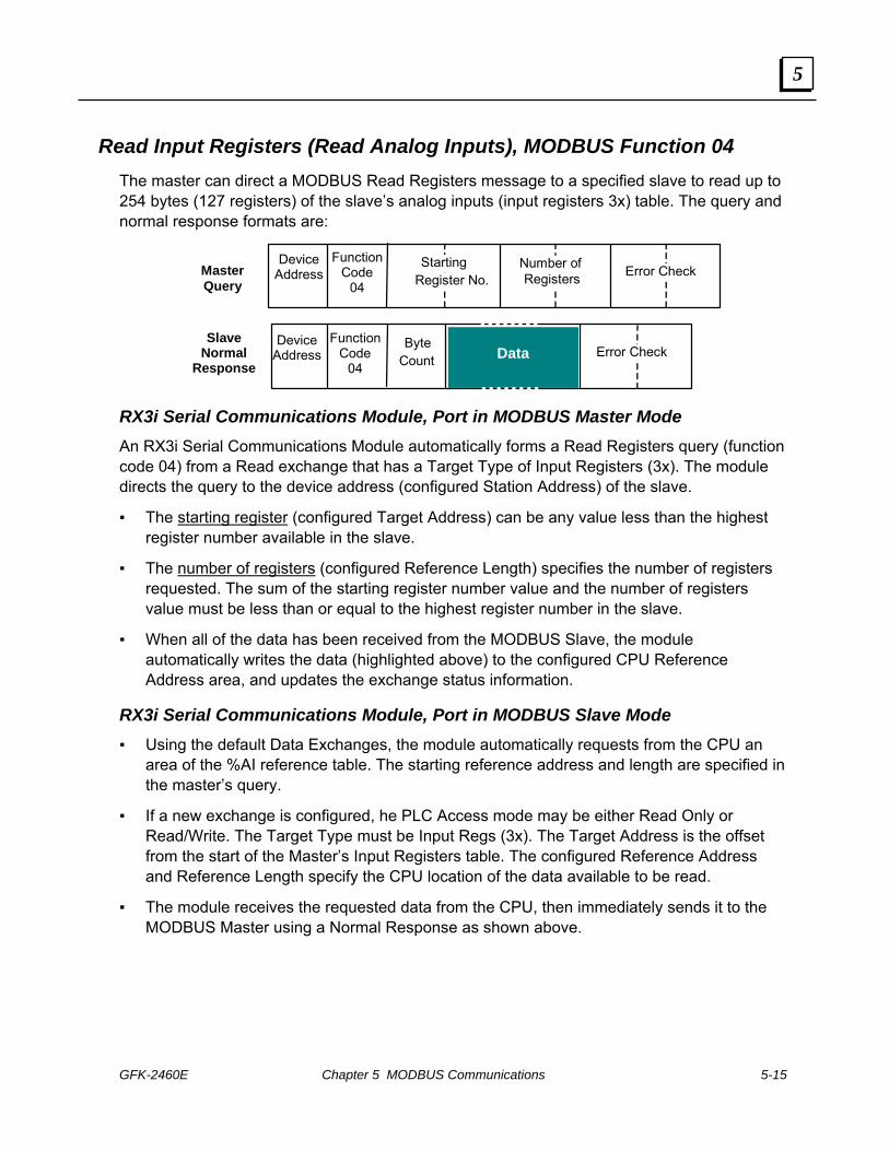
GFK-2460E Chapter 5 MODBUS Communications 5-15
5
Read Input Registers (Read Analog Inputs), MODBUS Function 04 The master can direct a MODBUS Read Registers message to a specified slave to read up to 254 bytes (127 registers) of the slave’s analog inputs (input registers 3x) table. The query and normal response formats are:
Error Check
Device Address
Function Code
04Master Query
Data ByteCount
Slave Normal
Response Device
Address Function
Code 04
Register No.Starting
Error Check Number ofRegisters
RX3i Serial Communications Module, Port in MODBUS Master Mode An RX3i Serial Communications Module automatically forms a Read Registers query (function code 04) from a Read exchange that has a Target Type of Input Registers (3x). The module directs the query to the device address (configured Station Address) of the slave.
The starting register (configured Target Address) can be any value less than the highest register number available in the slave.
The number of registers (configured Reference Length) specifies the number of registers requested. The sum of the starting register number value and the number of registers value must be less than or equal to the highest register number in the slave.
When all of the data has been received from the MODBUS Slave, the module automatically writes the data (highlighted above) to the configured CPU Reference Address area, and updates the exchange status information.
RX3i Serial Communications Module, Port in MODBUS Slave Mode Using the default Data Exchanges, the module automatically requests from the CPU an
area of the %AI reference table. The starting reference address and length are specified in the master’s query.
If a new exchange is configured, he PLC Access mode may be either Read Only or Read/Write. The Target Type must be Input Regs (3x). The Target Address is the offset from the start of the Master’s Input Registers table. The configured Reference Address and Reference Length specify the CPU location of the data available to be read.
The module receives the requested data from the CPU, then immediately sends it to the MODBUS Master using a Normal Response as shown above.

5-16 PACSystems* RX3iSerial Communications Modules – June 2010 GFK-2460E
5
Force Single Coil, MODBUS Function 05 The master can issue a MODBUS Force Single Coil message to a specified slave or to all slaves to change the state of one point in the discrete outputs (coils 0x) table. The specified output is forced automatically. This command is not an output override command. The output is guaranteed to be forced only once.
Device Address
Function Code
05Master Query
Slave Normal
Response
NumberPoint
Error Check Data
00H
Device Address
Function Code
05 NumberPoint
Error Check Data
00H
RX3i Serial Communications Module, Port in MODBUS Master Mode This function is not available for an RX3i Serial Communications module port in MODBUS Master mode.
RX3i Serial Communications Module, Port in MODBUS Slave Mode Using the default Data Exchanges, the Serial Communications module automatically
writes to the CPU %Q reference table. The starting reference address and length are specified in the master’s query.
A new exchange can be configured that maps some amount of %Q memory to coils. The PLC Access mode must be Read/Write. The Target Type must Coils (0x). The Target Address is the offset from the start of the Master’s Input Registers table. The configured Reference Address and Reference Length specify the CPU location of the coils available to be forced by the master.
After writing the received data to the CPU, the module replies to the MODBUS Master using a normal response as shown above. The normal response to a force single output query is identical to the query.

GFK-2460E Chapter 5 MODBUS Communications 5-17
5
Preset/Write Single Register, MODBUS Function 06 The master can issue a MODBUS Preset/Write Single Register message to one slave or to all slaves, to set a single register in the registers (holding registers, 4x) table. The register is written automatically.
DataHigh Low
Device Address
Function Code
06Master Query
Slave Normal
Response
NumberRegister
Error Check DataHigh Low
Device Address
Function Code
06 NumberRegister
Error Check
High Low
High Low
RX3i Serial Communications Module, Port in MODBUS Master Mode An RX3i Serial Communications Module automatically forms a Preset/Write Single Register query (function code 06) from a Write exchange that has a Target Type of Holding Registers (4x) and a length of 1 register. The module directs the query to the device address (configured Station Address) of the slave
The register number (configured Target Address) can be any register available in the slave.
The data field is two bytes in length. The module supplies this data from the register value received from the CPU.
As soon as the module receives the data from the CPU, it writes the query to the MODBUS Slave.
RX3i Serial Communications Module, Port in MODBUS Slave Mode Using the default Data Exchanges, the Serial Communications module automatically
writes to the CPU %R reference table. The starting reference address and length are specified in the master’s query.
If a new exchange is configured, the PLC Access mode must be Read/Write. The Target Type must Holding Registers (4x). The configured Reference Address and Reference Length specify the CPU location of the data available to be written to.
The module writes the received data to the CPU, then immediately replies to the MODBUS Master using a normal response as shown above. The normal response to a preset single register query is identical to the query.

5-18 PACSystems* RX3iSerial Communications Modules – June 2010 GFK-2460E
5
Read Exception Status, MODBUS Function 07 The master can direct a Read Exception Status MODBUS message to a specified slave to read the first eight output points.
Device Address
Function Code
07Master Query
Slave Normal
Response
Error Check
Device Address
Function Code
07Error CheckData
RX3i Serial Communications Module, Port in MODBUS Master Mode The Read Exception Status function (function code 07) is not explicitly supported by RX3i Serial Communications modules RX3i Serial Communications Module, Port in MODBUS Master mode. Configuring a Read exchange with a length of Target Type of Coils (0x) and a Target Address of 1 will accomplish the same function.
The module automatically forms a Read Coils query from the configured exchange, and directs it to the slave.
The data field of the normal response is one byte in length. It contains the states of output points one through eight. The output states are packed in order of number with output point one’s state in the least significant bit and output point eight’s state in the most significant bit. As soon as all of the data has been received, the module automatically writes it to the configured CPU Reference Address area.
RX3i Serial Communications Module, Port in MODBUS Slave Mode Using the default Data Exchanges, the Serial Communications module automatically
requests the first 8 bits in the CPU’s %Q reference table.
If a new exchange is configured, the PLC Access mode may be either Read Only or Read/Write. The Target Type must be Coils (0x). The Target Address is the offset from the start of the Master’s Coils table. The configured Reference Address and Reference Length specify the CPU location of the data available to be read.
The module receives the requested data from the CPU, then immediately sends it to the MODBUS Master using a Normal Response as shown above.

GFK-2460E Chapter 5 MODBUS Communications 5-19
5
Diagnostics, Return Query Data, MODBUS Function 08 The master can direct a MODBUS Diagnostic (Loopback Maintenance) query to a specified slave to test the slave’s ability to mirror the same data back to the master. The query and normal response formats are:
Device Address
Function Code
08Master Query
Slave Normal
Response
Code 00Diagnostic
Error Check
Device Address
Function Code
08Error Check
Code 00Diagnostic
Data
Data
RX3i Serial Communications Module, Port in MODBUS Master Mode An RX3i Serial Communications Module automatically forms a Diagnostics query (function code 08) with a Diagnostic Code of 00 from a Read Exchange that has a Target Type of Return Query Data.
The module requests from the CPU two bytes of data from the configured Reference Address location. The values of the two data field bytes in the query are arbitrary.
After receiving the data from the CPU, the module directs the query to the slave
The module waits for the slave to return a copy of the query.
RX3i Serial Communications Module, Port in MODBUS Slave Mode No exchange configuration is needed. The Serial Communications module automatically responds with a copy of the master’s query, regardless of whether or not it is configured for Preconfigured Exchanges This command does not cause the module to exchange any data with the CPU.

5-20 PACSystems* RX3iSerial Communications Modules – June 2010 GFK-2460E
5
Write Multiple Coils (Force Multiple Outputs), MODBUS Function 15 The MODBUS Master can issue a Write Multiple Coils message to force up to 254 contiguous points in one slave’s or all slaves’ discrete outputs (coils 0x) table. The specified outputs are forced automatically. Write Multiple Coils is not an output override command. The outputs are guaranteed to be forced only once. The query and normal response formats are:
Error Check
Device Address
Function Code
15
Master Query
Data Byte
Count
Slave Normal
Response
Device Address
Function Code
15
Point NumberStarting
Error Check Number ofPoints
Point NumberStarting Number of
Points
RX3i Serial Communications Module, Port in MODBUS Master Mode An RX3i Serial Communications module automatically forms a Write Multiple Coils query (function code 15) from a Write exchange that has a Target Type of Coils (0x).
The module requests the content of the configured CPU reference address. The values for the output points must be ordered by number starting with the LSB of the first byte.
The number of points is based on the configured reference length.
As soon as the module receives the data from the CPU, it directs the query to the device address (configured Station Address) of the slave.
The starting point number configured as the Target Address can be any value less than the highest output point number available in the slave. The sum of the starting point number and the number of points value must be less than or equal to the highest output point number available in the slave. If the number of points is not a multiple of 8, the last data byte contains zeros in its higher order bits.
RX3i Serial Communications Module, Port in MODBUS Slave Mode Using the default Data Exchanges, the Serial Communications module automatically
writes to the CPU %Q discrete outputs. The starting reference address and length are specified in the master’s query.
If a new exchangeis configured, the PLC Access mode must be Read/Write. The Target Type must Coils (0x). The configured Reference Address and Reference Length specify the CPU location of the data to be written.
The module writes the received data to the CPU, then immediately replies to the MODBUS Master using a normal response as shown above.

GFK-2460E Chapter 5 MODBUS Communications 5-21
5
Preset/Write Multiple Registers, MODBUS Function 16 The master can issue a MODBUS Preset/Write Multiple Registers message to preset a group of up to 127 contiguous registers in one slave or all slaves to a specified value.
RX3i Serial Communications Module, Port in MODBUS Master Mode An RX3i Serial Communications module automatically forms a Preset/Write Multiple Registers query (function code 16) from a Write exchange that has a Target Type of Holding Registers (4x).
The module requests the content of the configured CPU references addresses, to be written in the query.
The starting register number (configured Target Address) can be any value less than the highest register number available in the slave.
The number of registers (configured Reference Length) specifies the number of registers to write. The sum of the starting register number (configured Target Address) and the configured Reference Length must be less than or equal to the highest register number available in the slave.
As soon as the module receives the data (highlighted above) from the CPU, it directs the query to the device address (configured Station Address) of the slave.
RX3i Serial Communications Module, Port in MODBUS Slave Mode Using the default Data Exchanges, the Serial Communications module automatically
writes to the CPU %R registers. The starting reference address and length are specified in the master’s query.
If a new exchange is configured, the PLC Access mode must be Read/Write. The Target Type must Registers (4x). The configured Reference Address and Reference Length specify the CPU location of the data to be written.
The module writes the received data to the RX3i CPU, then immediately replies to the MODBUS Master using a normal response as shown above.
Device Address
Function Code
16 Error CheckMaster
Query
Slave Normal
Response
Starting Register Number
Device Address
Function Code
16
Byte Count
Error Check
Number of
Registers
Starting Register Number
Number of
Registers
Data
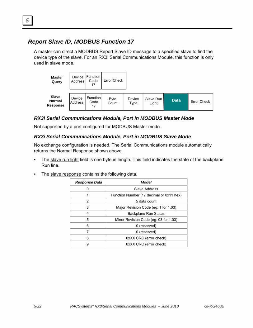
5-22 PACSystems* RX3iSerial Communications Modules – June 2010 GFK-2460E
5
Report Slave ID, MODBUS Function 17 A master can direct a MODBUS Report Slave ID message to a specified slave to find the device type of the slave. For an RX3i Serial Communications Module, this function is only used in slave mode.
Device Address
Function Code
17 Error Check
Master Query
Slave Normal
Response Byte
Count
Data
Device Address
Function Code
17
Slave Run Light
Error Check
Device Type
RX3i Serial Communications Module, Port in MODBUS Master Mode Not supported by a port configured for MODBUS Master mode.
RX3i Serial Communications Module, Port in MODBUS Slave Mode No exchange configuration is needed. The Serial Communications module automatically returns the Normal Response shown above.
The slave run light field is one byte in length. This field indicates the state of the backplane Run line.
The slave response contains the following data.
Response Data Model
0 Slave Address 1 Function Number (17 decimal or 0x11 hex) 2 5 data count 3 Major Revision Code (eg: 1 for 1.03) 4 Backplane Run Status 5 Minor Revision Code (eg: 03 for 1.03) 6 0 (reserved) 7 0 (reserved) 8 0xXX CRC (error check) 9 0xXX CRC (error check)

GFK-2460E Chapter 5 MODBUS Communications 5-23
5
Mask Write 4x Memory (Register Table), MODBUS Function 22 The master can issue MODBUS message Mask Write 4x Memory (function code 22) to modify the content of a specified register in slave Register (Holding Registers, 4x) memory. The query and response formats are:
Device Address
Function Code
22 Error Check
Master Query
Slave Normal
Response
Register Number
Device Address
Function Code
22 Error Check
Register Number
OR Mask
AND Mask
OR Mask
AND Mask
RX3i Serial Communications Module, Port in MODBUS Master Mode This function is not supported by an RX3i Serial Communications module port configured for MODBUS Master mode.
RX3i Serial Communications Module, Port in MODBUS Slave Mode Using the default Data Exchanges, the module automatically requests from the CPU an
area of the %R reference table. The starting reference address and length are specified in the master’s query.
If a new exchange is configured, the PLC Access mode must be Read/Write. The Target Type must be Holding Regs (4x). The Target Address is the offset from the start of the Master’s Holding Registers table. The configured Reference Address and Reference Length specify the CPU location of the data available to be written
When the module receives a query with function code 22, it automatically reads the contents of the two CPU registers that have been defined in the exchange. The module uses the query’s AND mask and OR values mask to change the register's current content:
Result = (Current Content AND And_Mask) OR (Or_Mask AND And_Mask )
Example Hex Binary
Current Contents 12 0001 0010 And_Mask F2 1111 0010 Or_Mask 25 0010 0101 And_Mask 0D 0000 1101 Result 17 0001 0111
The module returns the revised data to the same CPU registers, then replies to the master using the normal response shown above.
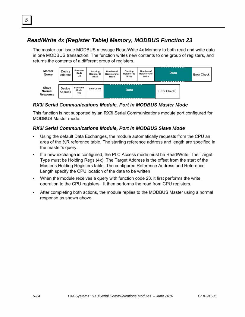
5-24 PACSystems* RX3iSerial Communications Modules – June 2010 GFK-2460E
5
Read/Write 4x (Register Table) Memory, MODBUS Function 23 The master can issue MODBUS message Read/Write 4x Memory to both read and write data in one MODBUS transaction. The function writes new contents to one group of registers, and returns the contents of a different group of registers.
Device
Address Function
Code 23 Error Check
Master Query
Slave Normal
Response
Starting Register to
Read
Device Address
Function Code 23 Error Check
Byte Count
Number of Registers to
Read
Starting Register to
Write
Number of Registers to
Write
Data
Data
RX3i Serial Communications Module, Port in MODBUS Master Mode This function is not supported by an RX3i Serial Communications module port configured for MODBUS Master mode.
RX3i Serial Communications Module, Port in MODBUS Slave Mode Using the default Data Exchanges, the module automatically requests from the CPU an
area of the %R reference table. The starting reference address and length are specified in the master’s query.
If a new exchange is configured, the PLC Access mode must be Read/Write. The Target Type must be Holding Regs (4x). The Target Address is the offset from the start of the Master’s Holding Registers table. The configured Reference Address and Reference Length specify the CPU location of the data to be written
When the module receives a query with function code 23, it first performs the write operation to the CPU registers. It then performs the read from CPU registers.
After completing both actions, the module replies to the MODBUS Master using a normal response as shown above.

GFK-2460E 6-1
Serial I/O Communications
This chapter describes the Serial I/O feature of RX3i Serial Communications modules. Serial I/O communications can be used to exchange up to 2K bytes of data with an individual serial device, such as a modem, that is connected to one of the module’s ports.
Serial I/O Communications for RX3i Serial Communications Modules
Serial I/O Features of Serial Communications Modules
Local Serial I/O Operations
Initializing (Resetting) the Port
Managing Hardware Flow Control for RS-232 Communications
Reading Serial I/O Data
Reading the Port Status
Flushing the Input Buffer
Reading Input Data
Writing Serial I/O Data
Dialing a Modem
Chapter
6

6-2 PACSystems* RX3iSerial Communications Modules – June 2010 GFK-2460E
6
Serial I/O Communications for RX3i Serial Communications Modules
PACSystems RX3i Serial Communications modules support the same Serial I/O protocol as the RX3i CPU. Serial I/O protocol can be used to communicate with a serial device, such as a modem, connected to one of the module’s ports. The module has a 2048-byte buffer to receive data from a serial device.
Serial I/O Features of Serial Communications Modules PACSystems RX3i Serial Communications modules provide the Serial I/O protocol features listed below. Unlike the PACSystems RX3i CPU, RX3i Serial Communications modules do NOT use Communication Request (COMMREQ) commands for Serial I/O. Instead, the CPU sets up data communications in the port’s configuration parameters, and controls communications through the status and control data that it exchanges with the module each I/O Scan (detailed in chapter 5, Status and Control Data).
For reference, the table below compares the Serial I/O functions implemented using COMMREQs in an RX3i CPU with the same functions for an RX3i Serial Communications module.
PACSystems RX3i CPU RX3i Serial Communications Module
Local functions – do not receive or transmit data through the serial port.
Initialize Port Set bit 67 (port reset) in the Port’s Control Data to 1.
Set Up Input Buffer No action necessary. The module automatically maintains a 2K memory buffer for Serial I/O data.
Flush Input Buffer Set bit 83 (flush input buffer) in the Port’s Control Data to 1.
Read Port Status Check the status bits in the Port’s Status Data.
Write Port Control Set bit 84 (activate RTS) in the Port’s Control Data to 1.
Cancel COMMREQ Operation
Not needed; you can cancel a pending receive or transmit by using bit 81 to cancel a receive or bit 82 to cancel a pending transmit.
Remote functions – receive and/or transmit data through the serial port.
Autodial Use multiple write operations of different lengths to dial the modem, send the data, and send the hang up sequence.
Write bytes Toggle bit 2 of the Port’s Control Data to initiate write.
Read bytes Toggle bit 1 of the Port’s Control Data to initiate read of specific data length.
Read String Toggle bit 1 of the Port’s Control Data to initiate read up to specified termination sequence.

GFK-2460E Chapter 6 Serial I/O Communications 6-3
6
Local Serial I/O Operations Local Serial I/O operations are performed by the CPU using the port’s control output data. The CPU automatically sends this data to the module each CPU sweep. It can also be sent using a DO I/O block in the application program. Details of the Port Control Output data are provided in chapter 4, Port Status and Control Data.
Initializing (Resetting) the Port Resetting a port stops processing on that port and restarts operation as though the port just received another configuration. Resetting the port initializes all port operations according to the port’s configuration.
To reset a port, the application logic sets bit 67 (Port Reset) in the port’s Port Control Data to 1. The port will only be reset again if the module sees another scan of the Port Reset bit still set to 1. The port remains in Reset if the CPU is not in Run mode. The port will reset again every time this bit is not set back to 0 for an output scan.
Managing Hardware Flow Control for RS-232 Communications RTS/CTS (Request to Send/Clear to Send) For RS-232 communication, if the port’s Flow Control parameter has been configured for Hardware Flow Control (RTS/CTS), the application should set output bit 84 (Activate RTS) in the port’s Port Control Data to 1 to force RTS on the port before transmitting.
The application should then check input bit 145 (CTS active). When this bit is 1, the port can safely transmit. If CTS does not become active within 2 seconds, the module returns a timeout error to the status location. If CTS becomes active and then de-asserts, additional data transmission must stop until CTS reasserts. After the last transmit character is sent, the application must set the RTS bit to 0.
RFR/CTS (Ready for Receiving/Clear to Send) If RFR/CTS is used, the application should check that CTS is active prior to any transmission. The application should assert CTS (which is handled as RFR) while it is ready to receive data. CTS should remain asserted until the application can no longer handle receiving. At that time it should de-assert CTS until it is ready to receive again.

6-4 PACSystems* RX3iSerial Communications Modules – June 2010 GFK-2460E
6
Reading Serial I/O Data When the module receives Serial I/O input data, it automatically stores the data in the 2048-byte input buffer. If the buffer becomes full, any additional data received from the serial port is lost. The application logic can monitor port status to see how much space is used in the input buffer. The application logic is responsible for reading data out of the buffer in a timely manner, so that incoming data will not be lost. The application can also flush the input buffer, which removes input data that has not yet been read.
Reading the Port Status Each CPU sweep, the module automatically informs the CPU of the status of the Serial I/O input buffer in the Port Status input data. The application logic should monitor this status to be sure input data is not lost.
Port input bits 161-176 (word data) contain the number of input buffer characters that have been received.
Port input bits 177-192 (word data) contain the number of input buffer characters that were last transferred from the input buffet to PLC memory. This makes it possible to determine how many bytes of the last received data are new.
Flushing the Input Buffer The port’s Serial I/O input buffer can be cleared by setting bit 83 (flush input buffer) in the Port Control output data to 1. This operation empties the input buffer of any characters received through the serial port but not yet read by the CPU. If the application tries to flush the buffer while a read operation is pending, the read buffer operation is executed first, then the buffer is cleared of all remaining data.

GFK-2460E Chapter 6 Serial I/O Communications 6-5
6
Reading Input Data The application logic in the RX3i CPU is responsible for reading data from the input buffer into its assigned CPU reference area.
1. To read Serial I/O data from the RX3i Serial Communications module’s input buffer, the application program toggles bit 1 of the Port’s Control output data to the opposite state.
2. The module reads the requested data from its internal buffer. The amount of data transferred depends on the parameters that were chosen for the Serial I/O Read configuration:
Read Input Buffer Only: If the Read Control Operation configuration parameter is set to Receiving Disabled, the receive transaction will only read data bytes that are already in the port’s input buffer. The number of bytes actually read is indicated in the word of data between bits 177 – 192 of the port’s input status data
Read a Data String: If the Read Control Operation parameter is configured for Read Delimiter, the module reads data until the specified termination sequence occurs, or until an error is detected. If a Timeout value has been configured and a timeout occurs before the termination sequence is received, any data collected before the timeout is discarded. If the terminating character cannot be found, the receive operation terminates immediately.
Read Fixed Byte Count: If the port’s Read Control Operation is configured for Byte Count, the module will return all data from the serial channel up to the specified number of bytes. If the length is set to 0, all bytes in the port’s input buffer will be received. The word of data between bits 177 – 192 of the port’s input status data indicates the number of bytes read. If there are no characters in the port’s input buffer, the module terminates the receive operation immediately. The module sets the port’s Exchange Error Report bit to 1 and the “received character count” to 0.
Read Dynamic Byte Count: If the port’s Read Control Operation is configured for Dynamic Read Length, the application sends the number of bytes to be read in the word between bits 97-112 of the Port Control Data. The module then reads the data as described above for Read Fixed Byte Count.
3. The module immediately sends the serial data to the CPU.
4. The module updates the port’s error status, received character count, and input buffer characters available information in the Port Status data, and sets input bit 1 to match the state of output bit 1. When these two bits match, it indicates that the Serial I/O read has been completed.

6-6 PACSystems* RX3iSerial Communications Modules – June 2010 GFK-2460E
6
Writing Serial I/O Data The CPU references to be used for serial data and the length of data that will be written in each transmission are set up in the port configuration. The application logic controls transmission of serial data using the port’s status and communications data, which is explained in more detail in chapter 4.
To write data to a Serial I/O device, the application should:
1. Application program toggles Port Control output bit 2 to the opposite state to initiate the next packet transfer.
2. The Serial Communications module responds by immediately requesting the contents of the configured Serial I/O transmit references from the CPU (the data should not be changed until the operation is complete). For example:
Data Values 6568 ‘h’ (68h), ‘e’ (65h)
6C6C ‘l’ (6Ch), ‘l’ (6Ch)
006F ‘o’ (6Fh)
Although printable ASCII characters are used in this example, there is no restriction on the values of the characters that can be transmitted.
3. The amount of data transferred depends on the parameters that were chosen for the Serial I/O Write configuration:
Write Fixed Byte Count: If the port’s Write Length Source is configured for Static Write Length, the module will write the configured number of bytes.
Write Dynamic Byte Count: If the port’s Write Length Source is configured for Dynamic Write Length, the application sends the number of bytes to be read in the word between bits 113-128 (word 16) of the Port Control Data.
4. The CPU provides the requested data to the module.
5. The status of the operation is not complete until all of the characters have been transmitted or until a timeout occurs (for example, if hardware flow control is being used and the remote device never enables the transmission). After transmitting all of the data, the module updates any error status in the Port Status Data, and sets bit 2 of the Port Status input data to the same state as output bit 2.
6. The application logic should monitor status bit 2. When input bit 2 and output bit 2 are the same, it indicates that the last transmission was completed successfully.

GFK-2460E Chapter 6 Serial I/O Communications 6-7
6
Dialing a Modem Serial I/O writes can be used to dial a modem and send a specified byte string. For example, pager enunciation can be implemented by three commands, requiring three commands:
Dial the modem.
Specify an ASCII string to be sent from the serial port.
Sending the hang-up command string. It is the responsibility of the application logic to hang up the connection..
Command Strings to Dial or Hang Up a Modem
Commonly-used command strings for Hayes-compatible modems are listed below:
Command String Length Function
ATDP15035559999<CR> 16 (10h) Pulse dial the number 1-503-555-9999 ATDT15035559999<CR> 16 (10h) Tone dial the number 1-503-555-9999 ATDT9,15035559999<CR> 18 (12h) Tone dial using outside line with pause ATH0<CR> 5 (05h) Hang up the phone ATZ <CR> 4 (04h) Restore modem configuration to internally
saved values
For example, these strings tone-dial the number 234-5678 using a Hayes-compatible modem.
Data Values 5441h A (41h), T (54h) 5444h D (44h), T (54h) 3332h Phone number: 2 (32h), 3 (33h) 3534h 4 (34h), 5 (35h) 3736h 6 (36h), 7 (37h) 0D38h 8 (38h) <CR> (0Dh)


GFK-2460E 7-1
CCM Communications
Built-in CCM slave protocol allows a PACSystems RX3i Serial Communications module (revision 1.10 or later) to communicate with a variety of devices. Communications characteristics are set up primarily within the module’s configuration as described in chapter 3, Configuration. Chapter 4, Port Status and Control Data, details the data that is automatically exchanged between the module and the RX3i CPU each I/O Scan. The application uses that automatic data transfer to control and monitor communications through each port.
This chapter describes CCM Slave operations for RX3i Serial Communications modules.
CCM Overview
CCM Commands Supported by RX3i Serial Communications Modules
CCM Slave Operations for the Serial Communications Module Write Request from the CCM Master Normal Read Request from the CCM Master Quick Read Request from the CCM Master
Scratchpad Data
Diagnostics Data for CCM Slave Ports
Chapter
7

7-2 PACSystems* RX3iSerial Communications Modules – June 2010 GFK-2460E
7
CCM Overview CCM protocol is a serial communications protocol used by GE Intelligent Platforms Programmable Logic Controllers (PLCs) to share data between PLCs, or between PLCs and a host computer.
Master
Slaves
Multi-Drop Network Point-to-Point Connection
Master Slave
The Master may download data to the slave stations, or upload data from the Slave stations. Slave stations only respond to requests from the Master station and cannot initiate communications. Masters cannot "broadcast" a message to all Slaves.
CCM Networks use the RS-232 / RS-422 communication standards. RS-422/485 is necessary for a multi-drop Master-Slave network. Communication is asynchronous, half-duplex at speeds up to 115.2K baud. To avoid data collisions on a multi-drop network, slaves only “speak when spoken to”.
A PACSystems Serial Communications Module port can be used as a CCM Slave only, on either a point-to-point or multidrop link. The link may include other CCM-compatible devices: Series 90-70 Communications Coprocessor Module, IC697CMM711 Series 90-70 Programmable Coprocessor Module, IC697PCM711 Series 90-30 Communications Coprocessor Module, IC693CMM311 Series 90-30 Programmable Coprocessor Module, IC693PCM300, 301, or 311
CCM protocol is NOT available on Series 90 CPU serial ports.
CCM protocol was originally developed for Series Six Communications Control Modules (CCMs), such as IC600CB536, IC600CB537, and IC600BF948.
Instructions for using CCM protocol on other modules are not included here. For Series 90 CCM applications, refer to the Series 90 PLC Serial Communications Manual, GFK-0582D. For Series 90 PCM applications, refer to the Series 90 Programmable Coprocessor Module Manual, GFK-0255K. For Series Six CCM applications, refer to the Series Six PLC CCM Communications Manual, GFK-25386A. These documents are available on the Support website, and on the Infolink CD documentation library.

GFK-2460E Chapter 7 CCM Communications 7-3
7
CCM Commands for RX3i Serial Communications Modules As a CCM Slave, an RX3i Serial Communications Module supports the CCM Master commands listed below. The Command Numbers listed in the left column are used in the Master’s application program to identify the command to be executed; they are not part of the CCM communication itself, and they are not relevant to the RX3i Serial Communications Module.
Master Command Number
Command Description for CCM Masters
Implementation for RX3i Serial Communications Modules
[6001] Set Q Response. Local command, which passes four bytes of data from the CPU to the CCM interface.
CCM Command number not supported. This function is automatically handled in the module’s Port Control Output data, as described in chapter 4.
[6002] Clear CCM Status Words. Local command
CCM Command number not supported. This function is handled with the Clear CCM Errors Control bit.
[6003]
Read CCM Diagnostic Status Words. Local command, which reads CCM Diagnostic Status Words from CCM interface to CPU.
CCM Command number not supported. This function is handled by configuring a Data Exchange to read Diagnostic Status data from the module to a memory location in the RX3i CPU.
[6004] Software Configuration. Local command. CCM Command number not supported. This function is handled by port configuration in Machine Edition.
6101 Read from Target (slave) to Source (CCM Master) Register Table
6102 Read from Target (slave) to Source (CCM Master) Input Table
6103 Read from Target (slave) to Source (CCM Master) Output Table
Read/Write Register Table Data Exchange sets up CCM Master reads to any specified RX3i memory area, as configured. Multiple memory areas and types can be configured.
6109 Read Q-Response to Source Output Table.
The module returns the requested data to the Master.
6110
Single Bit Write. This function writes one bit to %I or %Q. Bit may be set to 1 or cleared to 0, depending on the memory type specified, as explained in the CCM Master documentation.
Configured Data Exchanges in the Serial Communications Module define Input Table B set and/or clear, and Output Table Bit set and/or clear. Multiple memory areas and types can be configured.
6111
Write to Target from Source Register Table. This function writes a specified number of words from Master to %R Register Table
6112 Write to Target from Source Input Table. This function writes a specified number of bits from Master to %I Input Table
6113
Write to Target from Source Output Table. This function writes a specified number of bits from Master to %Q Output Table
Read/Write Register Table Data Exchange sets up CCM Master writes to any specified RX3i memory area, as configured. Multiple memory areas and types can be configured.

7-4 PACSystems* RX3iSerial Communications Modules – June 2010 GFK-2460E
7
CCM Memory Types RX3i Serial Communications modules permit the CCM Master to perform the following read or write operations. By default, CCM Memory Types 1-3 and 13-18 are set up in the Serial Communications Module to access the conventional CCM Memory Types. However, the CCM Master can also access other memory types, as described in chapter 3.
CCM MemoryType
Description Memory Type in RX3i Slave accessed by CCM
Read Write
1 CPU Register Table Defaults to %R – Register Table * yes yes
2 CPU Input Table Defaults to %I – Input Table * yes yes 3 CPU Output Table Defaults to %Q – Output Table * yes yes 6 CCM Scratchpad * * CCM Scratchpad in module Yes no 9 CCM Diagnostic Status
Words * * CCM Diagnostic Status Words *** yes yes
13 Input Table Bit Set Defaults to %I – Input Table * yes
14 Output Table Bit Set Defaults to %Q – Output Table * yes
17 Input Table Bit Clear Defaults to %I – Input Table * yes
18 Output Table Bit Clear Defaults to %Q – Output Table *
Not applicable
yes
* can be configured in Serial Communications Module to access any RX3i CPU memory type: %R, %AI, %AQ, %W, %M, %Q, %T, %I.
** These types are stored internally in the RX3i Serial Communications module; they are not mapped to PLC memory by default. A Read Exchange can be programmed in the exchange table to allow local access to the CCM Diagnostic Status Words only (not Scratchpad).
*** The Master can clear the CCM Diagnostic Status Words by writing zeros to the seven Diagnostic Status words.

GFK-2460E Chapter 7 CCM Communications 7-5
7
CCM Slave Operations for the Serial Communications Module Because an RX3i Serial Communications Module can only be used as a CCM Slave, this manual does not include detailed information about implementing CCM communications. CCM Slave operation for the RX3i Serial Communications Module is summarized below.
Write Request from the CCM Master The Master can write up to 2K bytes of data to the RX3i CPU.
A Write Request from the Master starts with a “Normal” (N) Enquiry, which has the ASCII character N as its first byte. The Slave acknowledges the Enquiry with an ACK character (or a NAK if the Slave port is busy). The Master then sends the slave a 17-byte Header message that specifies the type of communication being requested (write, target memory address, data length).
Master
Slave
N
Slav
e ID
E
NQ
N
Sla
ve ID
A
CK
SO
H
17 B
yte
Hea
der
ETB
LR
C
AC
K
STX
Fu
ll D
ata
Blo
ck
ETB
LR
C
AC
K
STX
La
st D
ata
Blo
ck
ETB
LR
C
AC
K
EO
T
Module sends All Data to RX3i
CPU
After the Slave acknowledges receiving the Header, the Master sends the data. If there are more than 256 bytes of data, the data is sent in multiple blocks, each with the format shown above. All data blocks except the last have 256 data bytes. The Slave returns an ACK response after successfully receiving each individual data block.
The Serial Communications Module buffers the incoming data. After successfully receiving all of the data blocks, the Serial Communications Module transfers all of the data to the RX3i CPU in a single backplane communication. The transfer of data is generally completed within 4-16mS. However, if the module is running processor-intensive protocols on the other ports, it may take longer. The Serial Communications Module Slave then responds to the Master with an ACK character. Because it first must transfer the data to the CPU, the module takes longer to send ACK/NAK for the last block than the preceding data blocks. The Master responds with an End-of-Transmission character and the transaction is completed.
If the Serial Communications Module is not able to successfully transfer all of the data to the RX3i CPU, the Slave port sends an EOT character instead of ACK after the last data block, then goes to an idle state. If the CCM Master receives an EOT instead of an ACK after a Write Request, it should interpret the EOT as an indication that the write to the RX3i CPU did not occur.

7-6 PACSystems* RX3iSerial Communications Modules – June 2010 GFK-2460E
7
Normal Read Request from the CCM Master The Master can read up to 2K bytes of data from the RX3i CPU. The Read Request starts start with a “Normal” (N) Enquiry, which has the ASCII character N as its first byte. The Slave ACKnowledges the Enquiry (it sends a NAK if it is busy). The Master then sends the slave a 17-byte Header that specifies the type of communication being requested (read, target memory address, data length).
Master
Slave
N
Sla
ve ID
E
NQ
N
Sla
ve ID
A
CK
SO
H
17 B
yte
Hea
der
ETB
LR
C
AC
K
STX
Fu
ll D
ata
Blo
ck
ETB
LR
C
AC
K
STX
La
st D
ata
Blo
ck
ETB
LR
C
AC
K
EO
T
EO
T
After receiving a data read request, the Serial Communications module requests the data from the RX3i CPU. The CPU transfers all of the requested data to the module in a single backplane write. The transfer is generally completed within 4-16mS. However, if the module is running processor-intensive protocols on the other ports, it may take longer.
The Serial Communications Module Slave starts returning the data to the Master immediately after Acknowledging the Header. If the Master has requested more than 256 bytes of data, the data is returned in multiple blocks, each with the format shown above. All blocks except the last have 256 data bytes. The Master returns an ACK response after receiving each data block. After the Master acknowledges the last data block, the Slave returns an End of Transmission character to the Master. The Master responds with an End of Transmission character, ending the communication.
Quick Read Request from the CCM Master The Master can use a Quick Read request to read bytes 11 through 14 of the Port Control Output Data directly from the module. The application program is responsible for supplying appropriate content for these four bytes in the CPU. See chapter 4 for information about Port Control Output Data. A Quick Read Enquiry starts with the ASCII character Q as its first byte.
Master
Slave
Q
Sla
ve ID
E
NQ
STX
Fu
ll D
ata
Blo
ck
ETB
LR
C
After receiving a Quick Read Enquiry, the module immediately sends the 4 bytes of requested data from its internal memory. The Slave response ends the communication.

GFK-2460E Chapter 7 CCM Communications 7-7
7
Scratchpad Data Read-only Scratchpad memory in the Serial Communications Module can be read by the CCM Master. It is not accessible from the application program in the local CPU. Any element within the 256 byte range may be read. If the read request extends beyond the length of the scratchpad memory, the module replies with an NAK. The information within this memory is limited to a few parameters (see table). Valid Target Memory address range is 0 - 255.
Scratchpad Address
(Byte Offset) Field Identifier Definition/Bits
0x00 Outputs Enabled Status 1=Outputs enabled 0=Outputs disabled
0x01-0x0D Reserved Always 0. 0x0E CMM Firmware Revision Major 0x0F CMM Firmware Revision Minor 0x10-0x15 Reserved Always 0. 0x16 CCM CPU ID Number Slave: 1-90 (Decimal) 0x17-0xFF Reserved Always 0.

7-8 PACSystems* RX3iSerial Communications Modules – June 2010 GFK-2460E
7
Diagnostics Data for CCM Slave Ports The RX3i Communications Module keep a running total of errors. Diagnostic Status Words are independent for each port.
Word Offset Description
0 Byte 1: Spare Byte 2: Most Recent Error Code -see next page
1 Number of Successful Conversations (serial communications via the port)
2 Number of Aborted Conversations
3 Number of Header Retries
4 Number of Block Retries
5 Number of Non-Existent Exchanges Requests Received
6 RX3i Comms FW Version, MSB = Major, LSB = Minor (read only)
Diagnostic Status Words can be accessed in two ways:
From the Master, by reading the Diagnostic Status Words Target Memory Type through the serial port.
From the local CPU, using the Read Data Exchange in the Port Data – CCM Slave tab (not through the serial port)
.
Diagnostic status words can be cleared in two ways:
From the Master, by writing zeros over the Diagnostic Status Words Target Memory Type through the serial port.
From the local CPU, by setting the Clear CCM Errors bit (not through the serial port).

GFK-2460E Chapter 7 CCM Communications 7-9
7
Error Codes in the Diagnostic Status Words
Error Code
Hex Dec
Description
00 0 Successful Transfer
01 1 A time out occurred on the serial link
03 3 An external device attempted to read or write a non-existent I/O point (bit)
04 4 An external device attempted to access more data than is available in a particular memory type
05 5 An external device attempted to read or write an odd number of bytes to Register memory or the Diagnostic Status Words
06 6 An external device attempted to read or write one or more a non-existent Registers
07 7 An external device specified the transfer of zero data bytes
09 9 An external device attempted to transfer data to or from an invalid memory type or absolute source address
0A 10 An external device attempted to read or write one or more a non-existent Diagnostic Status Words
0C 12 Serial communication was aborted after a data block was retried three times, or more times than permitted
14 20 One or more of the following errors occurred during a data block transfer: An invalid STX (Start of Text) character was received An invalid ETB (End of Block) character was received An invalid ETX (End of Text) character was received An invalid LRC (Longitudinal Redundancy Check) character was received A parity, framing, or overrun error occurred
15 21 An EOT (End of Transmission) character was expected and not received
16 22 An ACK (Acknowledge) or NAK (Negative Acknowledge) character was expected and not received
1A 26 A timeout occurred during an attempt to transmit on a port due to CTS being in an inactive state too long
1D 29 An error occurred when data was being transferred between the Module and Backplane (Mail system error)
1E 30 A parity, framing, or overrun error occurred during a Header transfer
1F 31 A parity, framing, or overrun error occurred during a data block transfer
Transmission Errors CCM uses parity checking and LRC (longitudinal redundancy checking).
Parity checking is used to detect errors within a character. It can be configured as even, odd, or none. The parity bit is derived by the sender and monitored by the receiver.
LRC checking is used to detect errors in an entire block. The sending device inserts the LRC at the end of the header block and each block of data text. The receiving device generates its own block check character based on the incoming data and compares it to the transmitted

7-10 PACSystems* RX3iSerial Communications Modules – June 2010 GFK-2460E
7
LRC to detect errors. This is handled automatically by the Serial Communications Modules, if set up in the configuration.
Transmission Timing Errors
Timing problems between transmitter and receiver can produce transmission errors such as overrun, framing, and time-out errors. Overrun An Overrun error is reported if timing problems between the transmitter and receiver cause characters to be sent faster than the receiver can handle them. If that happens, the previous character is overwritten and an error is indicated. Framing Errors A Framing error is reported if the receiver mistakes a logic 0 data bit or a noise burst for a start bit. The error is detected because the receiver knows which bit after the start bit must be a logic 1 stop bit. If the start bit is really a data bit, and the expected stop bit is not the stop bit but a start or data bit the framing error will be reported. Timeout Errors Time-outs are used to ensure that a good link exists between devices during a communication. When a source device initiates a communication, the target must respond within a certain amount of time or a time-out will occur causing the communication to be aborted.
For an RX3i Serial Communications Module, timeouts are the sum of the base value shown below plus the configured Timeout (mS), plus the configured Turnaround Delay of 0 to 65,535 milliseconds. If the sum of the base timeout and the configured turnaround delay are greater than 65,535 (0xFFFF), 65,535 is used. Setting the Timeout parameter to 0 does not disable timeouts for the CCM Slave.
Condition Base Timeout in mSec Wait on ACK/NAK following ENQ 800
Wait on start of header following ACK of ENQ 800
Wait on header to finish 670
Wait on ACK/NAK following header 2000
Wait on start of data following ACK of header 20000
Wait on ACK/NAK following data block 20000
Wait on data block to finish 8340
Wait on EOT to close link 800

GFK-2460E 8-1
DNP3 Communications
For technical information about the DNP3 Master and Slave protocols, please refer to the documentation that is available at www.dnp.org. This chapter describes the specific implementation of DNP3 Master and DNP3 Slave for RX3i Serial Communications modules:
DNP3 for the RX3i Serial Communications Module DNP3 Master Operation of a Serial Communications Module Port
Serial Communications Module DNP V3.0 Master Device Profile Serial Communications Module DNP V3.0 Master Implementation Table Implementing DNP3 Master Functions
Reading Static Data from an Outstation Reading IIN Data from an Outstation Reading Change Event Data of Any Class from an Outstation Reading Class 1, 2, 3 Data from an Outstation Writing Binary or Analog Output Data to an Outstation: Direct Operate Writing Binary or Analog Output Data to an Outstation: Select then Operate
Issuing a Select Function to an Outstation Issuing an Operate Function to an Outstation
Writing Analog Input Deadband Data to an Outstation Reading Time and Date from an Outstation Writing Time and Date to an Outstation Sending a Cold Restart Command to an Outstation Clearing the Device Restart IIN Bit in an Outstation Enabling or Disabling Unsolicited Responses in an Outstation
DNP3 Slave Operation of a Serial Communications Module Port Serial Communications Module DNP V3.0 Slave Device Profile Serial Communications Module DNP V3.0 Slave Implementation Table Serial Communications Module DNP3 Slave Point Lists Implementing DNP3 Slave Functions
Creating Change Events for a DNP3 Slave Port Reporting Commanded Values Back to the Master Reporting Current Values to the Master
Chapter
8

8-2 PACSystems* RX3iSerial Communications Modules – June 2010 GFK-2460E
8
DNP3 for the RX3i Serial Communications Module Distributed Network Protocol Version 3.0 (DNP 3.0) is an open SCADA (system control and data acquisition) protocol.
DNP3 allows a master device to acquire information from and send control commands to remote devices using relatively small-sized packets. A single change in any state or value can be exchanged between the master and slave without transferring the large amounts of unchanged data. This is done by defining two different types of data a master can acquire from a slave; static data objects and change objects. The data that isn’t changing is represented by static data objects. These are the current values of the data points on the slave. Event objects are the historical values of data points that are associated with either a relative or absolute time stamp.
PACSystems RX3i Serial Communications modules (revision 1.20 or later) provide DNP3 Master and DNP3 Slave Level 1 operation. Either or both DNP3 protocols can be configured using Proficy Machine Edition. When either DNP3 protocol is enabled on any port on the module, other ports on the module can only be configured for DNP3 Master or DNP3 slave, or disabled. An RX3i Serial Communications Module supports these DNP3 features: DNP3 object types:
Binary Input Binary Output Status Control Relay Output Block 16-bit Analog Input Block 32-bit Analog Input Block Short Floating Point Long Floating Point 16-bit Analog Output Block Time and Date
DNP3 event object types (can also be reported with absolute or relative time): Binary Input Event 16-bit Analog Input Event 32-bit Analog Input Event Short Floating Point Change Long Floating Point Change
Time synchronization Polled report-by-exception (RBE) operation Unsolicited report-by-exception (URBE) operation Supports function codes for confirm, read, write, select, operate, direct operate (with or
without acknowledgement), assign class, cold restart and delay measurement Qualifier codes for start-stop index (0x0, 0x01), all points (0x06), limited quantity (0x07,
0x08) and indexed (0x17, 0x27, 0x28)

GFK-2460E Chapter 8 DNP3 Communications 8-3
8
DNP3 Master Operation of a Serial Communications Module Port
When a port on the Serial Communications Module is configured for DNP3 Master operation, it provides the following features: Up to 64 slave devices Supports the following DNP3 Function Codes:
Confirm (Function Code 0) Read (Function Code 1) Write (Function Code 2) Select (Function Code 3) Operate (Function Code 4) Direct Operate (Function Code 5) Direct Operate – No Response (Function Code 6) Cold Restart (Function Code 13) Enable Unsolicited Reponses (Function Code 20) Disable Unsolicited Reponses (Function Code 21) Assign Class (Function Code 22) Delay Measurement (Function Code 23) Response (Function Code 129, response from slave) Unsolicited Response (Function Code 130, response from slave)
Not all functions apply to all data objects. For a complete description of the function codes that apply to each supported object, please refer to the DNP Implementation Tables for a DNP3 Master, next in this chapter.
Module handles DNP3 functions automatically; user interface to DNP3 entirely through configuration of Data Exchanges and through the module’s Status and Control data.
Commands can be executed continuously or triggered by application logic
Updates assigned RX3i CPU memory based on change data received in slave responses, as well as from class report polls
Each master exchange can map up to 2K bytes of contiguous CPU memory to the selected object type
Up to 2k bytes of contiguous CPU memory can be assigned to a selected object type in each “slave like” exchange

8-4 PACSystems* RX3iSerial Communications Modules – June 2010 GFK-2460E
8
Serial Communications Module DNP V3.0 Master Device Profile DNP V3.00 DEVICE PROFILE DOCUMENT
Vendor Name: GE Intelligent Platforms Device Name: PACSystems RX3i Serial Communications Module Highest DNP Level Supported: For Requests: Level 1 For Responses: Level 1
Device Function: Master Slave
Notable objects, functions, and/or qualifiers supported in addition to the Highest DNP Levels Supported (the complete list is described in the attached table): Additional objects supported: 16-bit Analog Change Event with Time (Object 32, Variation 4) Can issue read requests for most objects. Can issue Assign Class function on the following objects:
Binary Input – Any Variation (Object 1, Variation 0) Analog Input – Any Variation (Object 30, Variation 0)
Maximum Data Link Frame Size (octets):
Transmitted: 292 Received 292
Maximum Application Fragment Size (octets):
Transmitted: 2048 Received: 2048
Maximum Data Link Re-tries:
None Fixed at ____ Configurable from 0 to 255 via Link
Maximum Retry Count field in port configuration
Maximum Application Layer Re-tries:
None Configurable
Requires Data Link Layer Confirmation:
Never Always Sometimes Configurable as: Never, Only for multi-frame messages, or Always via Link Layer Confirmation Mode in
port configuration. Requires Application Layer Confirmation:
Never Always When reporting Event Data When sending multi-fragment responses Sometimes Configurable
Timeouts while waiting for: Data Link Confirm: None Fixed at ____ Variable Configurable1 Complete Appl. Fragment: None Fixed at ____ Variable Configurable Application Confirm: None Fixed at ____ Variable Configurable 2 Complete Appl. Response: None Fixed at ____ Variable Configurable
Note 1: Data Link Confirm Timeout configurable via Link Confirmation Timeout field in port configuration.
Note 2: Application Confirm Timeout configurable via Application Response Timeout field in port configuration.

GFK-2460E Chapter 8 DNP3 Communications 8-5
8
DNP V3.00 DEVICE PROFILE DOCUMENT
Sends Control Operations: WRITE Binary Outputs Never Always Sometimes Configurable SELECT/OPERATE Never Always Sometimes Configurable DIRECT OPERATE Never Always Sometimes Configurable DIRECT OPERATE – NO ACK Never Always Sometimes Configurable Count > 1 Never Always Sometimes Configurable Pulse On Never Always Sometimes Configurable Pulse Off Never Always Sometimes Configurable Latch On Never Always Sometimes Configurable Latch Off Never Always Sometimes Configurable Queue Never Always Sometimes Configurable Clear Queue Never Always Sometimes Configurable Expects Binary Input Events:
Either time-tagged or non-time-tagged for a single event Both time-tagged and non-time-tagged for a single event Configurable
Sequential File Transfer Support: Append File Mode Yes No Custom Status Code Strings Yes No Permissions Field Yes No File Events Assigned to Class Yes No File Events Poll Specifically Yes No Multiple Blocks in a Fragment Yes No Max Number of Files Open N/A

8-6 PACSystems* RX3iSerial Communications Modules – June 2010 GFK-2460E
8
Serial Communications Module DNP V3.0 Master Implementation Table As a DNP3 Master, the RX3i Serial Communications module may receive responses from slaves that contain Change Event objects or static objects that it does not support. The module will parse all objects that any Level 1 slave may respond with.
The following table identifies the object variations, function codes, and qualifiers supported by a Serial Communications Module as a DNP3 Master. In the table, text shaded as 17, 28 indicates subset Level 2, 00, 01 indicates subset level 3 and 07, 08 indicates beyond level 3 functionality.
Object Request (Master may send)
Response (Master will parse)
Obj Var Description Func Codes (dec)
QualCodes (hex)
Func Codes (dec)
Qual Codes (hex)
1 06 1 0 Binary Input – Any Variation
22 01 06 07,08 17, 27, 28
1 1
Binary Input 129 00, 01 17, 28
1 2
Binary Input with Status 1 00,01 06 07,08 17, 27, 28
129 00, 01 17. 28
2 0 Binary Input Event – Any Variation 1 07 (limited qty = 1)
2 1 Binary Input Event without Time 129, 130 17, 28 2 2 Binary Input Event with Time 129, 130 17, 28 2 3 Binary Input Event with Relative
Time 129, 130 17, 28
10 0 Binary Output – Any Variation 1 06 10 1
Binary Output 129 00, 01
17, 28 10 2
Binary Output Status 1 00, 01
06 07, 08 17, 27, 28
129 00, 01 17,28
12 0 Control Relay Output Block
12 1 Control Relay Output Block 3 4 5 6
17, 28 129 echo of request
20 0 Binary Counter – Any Variation
20 1
32-Bit Binary Counter (with Flag)
20 2
16-Bit Binary Counter (with Flag)
20 5
32-Bit Binary Counter without Flag

GFK-2460E Chapter 8 DNP3 Communications 8-7
8
Object Request (Master may send)
Response (Master will parse)
Obj Var Description Func Codes (dec)
QualCodes (hex)
Func Codes (dec)
Qual Codes (hex)
20 6
16-Bit Binary Counter without Flag
21 0 Frozen Counter – Any Variation
21 1
32-Bit Frozen Counter (with Flag)
21 2
16-Bit Frozen Counter (with Flag)
21 5
32-Bit Frozen Counter with Time Of Freeze
21 6
16-Bit Frozen Counter with Time Of Freeze
21 9
32-Bit Frozen Counter without Flag
21 10
16-Bit Frozen Counter without Flag
22 0 Counter Change Event – Any Variation
22 1
32-Bit Counter Change Event without Time
129, 130 (see note 1)
17, 28
22 2
16-Bit Counter Change Event without Time
129, 130 (see note 1)
17, 28
22 5 32-Bit Counter Change Event with Time
22 6 16-Bit Counter Change Event with Time
23 0 Frozen Counter Event (Variation 0 is used to request default variation)
23 1 32-Bit Frozen Counter Event
23 2 16-Bit Frozen Counter Event
23 5 32-Bit Frozen Counter Event with Time
23 6 16-Bit Frozen Counter Event with Time
1 06
30 0 Analog Input - Any Variation
22 06 30 1
32-Bit Analog Input 1 00,01
06 07,08 17,27, 28
129 00, 01 17, 28
30 2
16-Bit Analog Input 1 00,01 06 07,08 17,27,28
129 00, 01 17, 28
30 3
32-Bit Analog Input without Flag 1 00,01 06 07,08 17,27, 28
129 00, 01 17, 28
30 4
16-Bit Analog Input without Flag 1 00,01 06
129 00, 01 17, 28

8-8 PACSystems* RX3iSerial Communications Modules – June 2010 GFK-2460E
8
Object Request (Master may send)
Response (Master will parse)
Obj Var Description Func Codes (dec)
QualCodes (hex)
Func Codes (dec)
Qual Codes (hex)
07,08 17,27, 28
30 5 short floating point
1 00,01 06 07,08 17, 27, 28
129 00, 01 17, 28
30 6 long floating point
1 00,01 06 07,08 17,27, 28
129 00, 01 17, 28
32 0 Analog Change Event – Any Variation
1 07 (limited quantity = 1)
32 1 32-Bit Analog Change Event without Time
129, 130 17, 28
32 2
16-Bit Analog Change Event without Time
129, 130 17, 28
32 3 32-Bit Analog Change Event with Time
129, 130 17, 28
32 4 16-Bit Analog Change Event with Time
129, 130 17, 28
32 5 Short Floating Point Analog Change Event without Time
129, 130 17, 28
32 6 Long Floating Point Analog Change Event without Time
129, 130 17, 28
32 7 Short Floating Point Analog Change Event with Time
129, 130 17, 28
32 8 Long Floating Point Analog Change Event with Time
129, 130 17, 28
34 0 Analog Input Deadband (Variation 0 is used to request default variation)
1
00, 01 06 07, 08 17, 28
129 00, 01 17, 28
34 1 16 bit Analog Input Deadband
2 17, 28 1 00, 01
06 07, 08 17, 28
129 00, 01 17, 28
34 2 32 bit Analog Input Deadband
2 17, 28 1
00, 01 06 07, 08 17, 28
129 00, 01 17, 28
34 3 Short Floating Point Analog Input Deadband
2 17, 28

GFK-2460E Chapter 8 DNP3 Communications 8-9
8
Object Request (Master may send)
Response (Master will parse)
Obj Var Description Func Codes (dec)
QualCodes (hex)
Func Codes (dec)
Qual Codes (hex)
40 0 Analog Output Status (Variation 0 is used to request default variation)
1
06
40 1
32-Bit Analog Output Status 1 00,01 06 07,08 17,27, 28
129 00, 01 17,28
40 2
16-Bit Analog Output Status 1 00, 01 06 07, 08 17, 27, 28
129 00, 01 17, 28
40 3 Short Floating Point Analog Output Status
1 00,01 06 07,08 17,27, 28
129 00, 01 17,28
40 4 Long Floating Point Analog Output Status
1 00,01 06 07,08 17,27,28
129 00, 01 17,28
41 0 Analog Output Block
41 1 32-Bit Analog Output Block 3 4 5 6
17, 28 129 echo of request
41
2
16-Bit Analog Output Block
3 4 5 6
17, 28 129 echo of request
41 3 Short Floating Point Analog Output Block
3 4 5 6
17, 28 129 echo of request
41 4 Long Floating Point Analog Output Block
3 4 5 6
17, 28 129 echo of request
50
0
Time and Date
1 07(limited qty = 1)
129 07(limited qty) (qty = 1)
50 1
Time and Date
2 07 (limited qty = 1)
50 3 Time and Date Last Recorded Time
51 1 Time and Date Common Time Object (CTO)
129, 130
07(limited qty) (qty = 1)
51 2 Unsynchronized Time and Date CTO
129, 130
07(limited qty) (qty = 1)
52 1 Time Delay Coarse 129 07(limited qty) (qty = 1)
52 2 Time Delay Fine 129 07(limited qty) (qty = 1)

8-10 PACSystems* RX3iSerial Communications Modules – June 2010 GFK-2460E
8
Object Request (Master may send)
Response (Master will parse)
Obj Var Description Func Codes (dec)
QualCodes (hex)
Func Codes (dec)
Qual Codes (hex)
60 0 Not Defined
60 1 Class 0 Data
1 22
06
1
06 07, 08(limited qty)
60 2 Class 1 Data
20 21 22
06
1
06 07, 08(limited qty)
60 3 Class 2 Data
20 21 22
06
1 06 07, 08 (limited qty)
60
4
Class 3 Data
20 21 22
06
1 00, 01 129 00, 01 80 1 Internal Indications 2 00
Index = 7
No Object (function code only) 13(cold restart) No Object (function code only) 23(delay
meas.)
Note 1: Object header in response will be parsed. The value will be ignored as and the CPU resident database will not be updated with the value since because the database does not support the object.

GFK-2460E Chapter 8 DNP3 Communications 8-11
8
Implementing DNP3 Master Functions Data Exchanges define DNP3 communications for the port, and map DNP3 data to CPU reference addresses. Up to 64 Data Exchanges can be configured for each port. Some sample Data Exchanges are shown below as they appear on the configuration screen.
For this Master DNP3 Function Use this Operation With this Function Possible Target Objects
Static Data, Time & Date, Internal Indicators.
Read (1)
Read Continuous, Read Continuous Bit-Control, or Read Single Bit-Control
Read Event Data, Class Data, Response Data can be read using multiple exchanges.
Write (2)
Write Continuous, Write Continuous Bit-Control, or Write Single Bit-Control
Write
16-bit Analog Input Deadband, 32-bit Analog Input Deadband, Short Floating Pt Alg In Deadbd, Time and Date, Internal Indicators
Select (3) Write Single Bit-Control, Write Continuous Bit-Control
Select
Operate (4) Write Single-Bit Control Operate Direct Operate with Acknowledge (5) Write Single-Bit Control Operate Direct with
ACK
Direct Operate w/o Acknowledge (6) Write Single-Bit Control Operate Direct No ACK
Control Relay Block, 32-Bit Analog Output Block, 16-Bit Analog Output Block, Short Floating Pt Alg Output Blk, Long Floating Pt Alg Output Blk
Cold Restart (13) Write Single-Bit Control Cold Restart none Enable Unsolicited Responses (20) Write Single-Bit Control Enable Unsolicited
Responses none
Disable Unsolicited Responses (21) Write Single-Bit Control Disable Unsolicited
Responses none
Assign Class (22) Write Single-Bit Control Assign Class (Requires subsequent Read function.)
Binary Input Any Variation, Analog Input Any Variation
Delay Measurement (23)
[none; module handles this automatically]
Response (129) Write Only
Slave Response (Requires subsequent Read function to read the data.)
Binary Input, Binary Output Status, 32-bit Analog Input, 16-bit Analog Input, 32-bit Analog Input without Flag, 16-bit Analog Input without Flag Short Floating Pt Analog Input, Long Floating Pt Analog Input, 32-bit Analog Output Status, 16-bit Analog Output Status, Short Floating Pt Analog Output,Long Floating Pt Analog Output

8-12 PACSystems* RX3iSerial Communications Modules – June 2010 GFK-2460E
8
Processing of Data Exchanges During Operation The Serial Communications module automatically translates the parameters of Data Exchanges into DNP3 functions. Some DNP3 functions require multiple Data Exchanges to implement, as explained in this section. The module stores a port’s configured Data Exchanges in its internal memory. During operation, the module scans the port’s Data Exchanges in order from 1 to 64, and carries out the defined functions.
If the Function of the Data Exchange is Slave Response (which is used to set up CPU data mapping but which does not generate a DNP3 action), the module skips to the next exchange.
If the Function is Cold Restart, the module issues a DNP3 Cold Restart command to the outstation (slave) having the specified Outstation Address.
If the Function is Select, the module retrieves the current data in the RX3i CPU Reference Addresses specified by that exchange and issues a DNP3 Select command for the data point(s) defined by the Outstation Address and Target Index fields of the Data Exchange.
If the Function is Read and the Target Object Type indicates a static data point or points, the module issues a DNP3 Read command to the outstation. When the module receives the data from the outstation, it automatically updates the CPU Reference Address area assigned in that Data Exchange.
If the Function is Read and the Target Object type indicates a single change event data object, the module requests the change event data from the outstation and updates the assigned data point(s) or the static data in the correct Write Only exchange.
If the Function is either Write or Operate, the module automatically retrieves the current data in the RX3i CPU Reference Addresses specified by that exchange. It then automatically sends the data to the outstation using a DNP3 Write or Operate command.
After executing an exchange, the module automatically:
1. Receives and parses the outstation slave's response. The values of DNP3 objects in the slave's response are written to the corresponding reference addresses in the CPU as defined in the executed exchange. If the slave's response was to a Read function of "Any Variation" target objects or a Read function with the Ref Length set to zero, denoting “all data points,” the master updates the corresponding references in the CPU as configured in the matching exchange with the function of Slave Response
2. If the slave needs time, the module will measure the delay and set the time on the slave.
3. Updates the exchange completion status. If the slave's application response had any IIN bits set and the configuration parameter 'Check Slave IIN' is enabled, the module sets the master exchange error code to 20 decimal. See chapter 4 for more information.

GFK-2460E Chapter 8 DNP3 Communications 8-13
8
Handling of Unsolicited Responses The slave attempts to send unsolicited responses containing change events in the way in which it is configured to do so. For additional information, see “Unsolicited Responses” on page 8-54.
If the master is configured to process unsolicited responses, it handles an unsolicited response from an outstation in much the same way that it handles an outstation response to a read request.
When the master receives an Unsolicited Response the CPU memory Reference Address, as configured in a matching exchange, is updated with the new value. An exchange is considered to be a match when it has a function of Slave Response, the same Outstation Address as the source of the Unsolicited Response, a Target Object that is the corresponding static DNP3 object for the received event object and a Target index range that is defined such that it contains the index of the static data point that the event object addresses.
Note: If any master (it doesn't have to be the master to which the slave sends the unsolicited responses), issues a read class 1, 2 or 3 command to the slave that reads all of the buffered change events, an unsolicited response will not be sent.
Programming Required for Data Exchanges The application logic in the RX3i CPU needs to handle the data that is read or written by a Serial Communications Module just like any other input, output, status, and control data. Data that will be written to outstations must be available in the assigned CPU reference address locations. Data received from outstations must be accessed from its assigned references and handled appropriately.
For DNP3 Master exchanges with an Operation type of Read Continuous, Write Continuous, or Write Only, the application logic does not need to do anything special to control the operation. For these exchanges, the module handles all data transfers with the CPU and with outstations automatically.
However, for DNP Master exchanges with an Operation type of Read Continuous Bit-Control, Read Single Bit-Control, Write Continuous Bit-Control or Write Single Bit-Control, the application program must control execution of the function. Each of the 64 potential Data Exchanges for a DNP3 Master port has a corresponding Port Control Output bit. The application program must initiate each execution of an exchange with an Operation type of Read Single Bit-Control or Write Single Bit-Control by toggling its Port Control Output bit. The application program must also start continuous execution of any exchange with an Operation type of Read Continuous Bit-Control or Write Continuous Bit-Control by setting its Port Control Output bit to 1. The application program can stop the continuous execution of any exchange with an Operation type of Read Continuous Bit-Control or Write Continuous Bit-Control by clearing its Port Control Output bit to 0.

8-14 PACSystems* RX3iSerial Communications Modules – June 2010 GFK-2460E
8
In addition the application logic should monitor DNP3 communications by:
1. Checking the Port Input Status Exchange Response data (see chapter 4).
2. Checking the Exchange Error Report bit that corresponds to the exchange to determine whether an error occurred.
3. Writing the Port Output Control Port Error Exchange Selector to obtain the Error Status for the given exchange.
4. If the Error Status is a DNP3 protocol specific status, such as the Master Exchange Error 'Slave IIN bits set', the application logic should check the DNP3 Exchange Error Status in the Port Input Status.
5. Acknowledging the error using the Port Output Control's Acknowledge Port Command. After acknowledging an error, the module is ready for the next exchange.
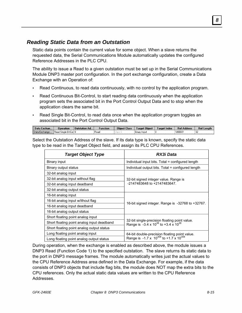
GFK-2460E Chapter 8 DNP3 Communications 8-15
8
Reading Static Data from an Outstation Static data points contain the current value for some object. When a slave returns the requested data, the Serial Communications Module automatically updates the configured Reference Addresses in the PLC CPU.
The ability to issue a Read to a given outstation must be set up in the Serial Communications Module DNP3 master port configuration. In the port exchange configuration, create a Data Exchange with an Operation of:
Read Continuous, to read data continuously, with no control by the application program.
Read Continuous Bit-Control, to start reading data continuously when the application program sets the associated bit in the Port Control Output Data and to stop when the application clears the same bit.
Read Single Bit-Control, to read data once when the application program toggles an associated bit in the Port Control Output Data.
Select the Outstation Address of the slave. If its data type is known, specify the static data type to be read in the Target Object field, and assign its PLC CPU References.
Target Object Type RX3i Data Binary input Individual input bits. Total = configured length Binary output status Individual output bits. Total = configured length 32-bit analog input 32-bit analog input without flag 32-bit analog input deadband 32-bit analog output status
32-bit signed integer value. Range is -2147483648 to +2147483647.
16-bit analog input 16-bit analog input w/ithout flag 16-bit analog input deadband 16-bit analog output status
16-bit signed integer. Range is -32768 to +32767.
Short floating point analog input Short floating point analog input deadband Short floating point analog output status
32-bit single-precision floating point value. Range is -3.4 x 1038 to +3.4 x 1038
Long floating point analog input Long floating point analog output status
64-bit double-precision floating point value. Range is -1.7 x 10308 to +1.7 x 10308
During operation, when the exchange is enabled as described above, the module issues a DNP3 Read (Function Code 1) to the specified outstation. The slave returns its static data to the port in DNP3 message frames. The module automatically writes just the actual values to the CPU Reference Address area defined in the Data Exchange. For example, if the data consists of DNP3 objects that include flag bits, the module does NOT map the extra bits to the CPU references. Only the actual static data values are written to the CPU Reference Addresses.

8-16 PACSystems* RX3iSerial Communications Modules – June 2010 GFK-2460E
8
Reading Floating Point Analog Data Short floating point analog in/output is a 32-bit floating point value, IEEE-754, The first bit is the sign bit, S, the next eight bits are the exponent bits, 'E', and the final 23 bits are the fraction 'F':
S EEEEEEEE FFFFFFFFFFFFFFFFFFFFFFF
Long floating point analog in/output is a 64-bit floating point value, IEEE-754. The first bit is the sign bit, S, the next eleven bits are the exponent bits, 'E', and the final 52 bits are the fraction 'F':
S EEEEEEEEEEE FFFFFFFFFFFFFFFFFFFFFFFFFFFFFFFFFFFFFFFFFFFFFFFFFFFF
Reading Static Data Using the “Any Variation” Types To read data from an outstation that does not support requests for specific data type variations, or if the exact Variation of the outstation’s data is not known, setting up the ability to read the data requires two Data Exchanges in the port configuration:
First, create a Data Exchange with an Operation of:
Read Continuous, to read data continuously, with no control by the application program.
Read Continuous Bit-Control, to start reading data continuously when the application program sets the associated bit in the Port Control Output Data and to stop when the application clears the same bit.
Read Single Bit-Control, to read data once when the application program toggles the associated bit in the Port Control Output Data.
Select the appropriate ‘Any Variation’ Target Object, for example: Binary Input Any Variation. Because the configuration does yet know the Object Variation, CPU Reference Addresses cannot be assigned for this type of exchange.
Then create a second, Write Only Data Exchange with the same Outstation Address, a Function of Slave Response, a suitable Target Object type, and CPU references for the data. The Reference Length specified in the Write Only exchange must accommodate all of the data from the outstation. Refer to the documentation for the outstation to help determine the correct size.
When the Read exchange is executed, the outstation will report back the value in its default variation. The reply includes an object header that defines its actual Object Variation. The Serial Communications Module uses that information to convert the data into a format that can be written to CPU memory. The module will automatically write the data into the assigned CPU references. If the selected data type includes a status flag, the status data is NOT mapped to the CPU references. Only actual static data values are written to the CPU.

GFK-2460E Chapter 8 DNP3 Communications 8-17
8
Reading IIN Data from an Outstation The ability to issue a Read to a given outstation must be set up in the Serial Communications Module DNP3 master port configuration. In the port exchange configuration, create a Data Exchange with an Operation of:
Read Continuous, to read data continuously, with no control by the application program.
Read Continuous Bit-Control, to start reading data continuously when the application program sets the associated bit in the Port Control Output Data and to stop when the application clears the same bit..
Read Single Bit-Control, to read data once when the application program toggles the associated bit in the Port Control Output Data.
Select the Outstation Address of the slave. As Target Object, choose Internal Indicators, and assign PLC CPU References where the data will be written.
During operation, when the exchange is enabled as described above, the module issues a DNP3 Read (Function Code 1) to the specified outstation. The slave returns its IIN data to the port. The module automatically writes the IIN data to the CPU Reference Address area defined in the Data Exchange.
IIN data consists of one word of bit-flags that indicate error conditions as well as general status.
15 14 13 12 11 10 9 8 7 6 5 4 3 2 1 0
MSB LSB
Reserved, always 0Configuration corrupt
Already executing requested operationEvent buffer overflow
Parameter errorObject unknown
Function code not supported
All Stations: broadcase message receivedClass 1 events available Class 2 events available Class 3 events available Need time: write time and date to slave Local control Device Trouble Device Restart

8-18 PACSystems* RX3iSerial Communications Modules – June 2010 GFK-2460E
8
Reading Change Event Data of Any Class from an Outstation If the application wants to read any change event data from an outstation (without specifying class 1, 2, or 3), and update the data in CPU memory, configure the exchanges described below.
First, create a Data Exchange with an Operation of:
Read Continuous, to read data continuously, with no control by the application program.
Read Continuous Bit-Control, to start reading data continuously when the application program sets the associated bit in the Port Control Output Data and to stop when the application clears the same bit.
Read Single Bit-Control, to read data once when the application program toggles the associated bit in the Port Control Output Data.
Select the Outstation Address of the slave. As Target Object, choose either Binary Input Event Any Variation or Analog Change Event Change Any Variation.
Then create a second, Write Only Data Exchange with the same Outstation Address, a Function of Slave Response, a suitable Target Object type (for example Binary Input), and CPU references for the data. The Reference Length should be 1.
During operation, when the Read exchange is enabled as described above, the DNP3 master port sends a request to the outstation for one binary input event or one analog input event of any variation. If there is a response, the module automatically maps the data to the RX3i CPU Reference Address location specified in the Slave Response exchange. The Slave Response exchange does not require any additional action to execute. The slave response is used to set up CPU data mapping of responses from Any Variation and All Points read requests as well as unsolicited responses.
If the selected data type from the outstation includes a status flag, the status data is not mapped to the CPU references. Only actual data values are written to the CPU.
In this example, if the Master is configured to process unsolicited responses, the outstation at address 4 responds as if the Master has issued the Read Single Bit-Control function shown. That outstation will send the change event with function 130 (unsolicited response), instead of 129 and the value in the change event will be written to %I0193.
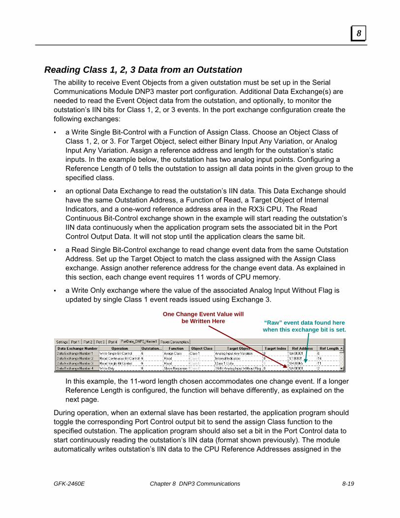
GFK-2460E Chapter 8 DNP3 Communications 8-19
8
Reading Class 1, 2, 3 Data from an Outstation The ability to receive Event Objects from a given outstation must be set up in the Serial Communications Module DNP3 master port configuration. Additional Data Exchange(s) are needed to read the Event Object data from the outstation, and optionally, to monitor the outstation’s IIN bits for Class 1, 2, or 3 events. In the port exchange configuration create the following exchanges:
a Write Single Bit-Control with a Function of Assign Class. Choose an Object Class of Class 1, 2, or 3. For Target Object, select either Binary Input Any Variation, or Analog Input Any Variation. Assign a reference address and length for the outstation’s static inputs. In the example below, the outstation has two analog input points. Configuring a Reference Length of 0 tells the outstation to assign all data points in the given group to the specified class.
an optional Data Exchange to read the outstation’s IIN data. This Data Exchange should have the same Outstation Address, a Function of Read, a Target Object of Internal Indicators, and a one-word reference address area in the RX3i CPU. The Read Continuous Bit-Control exchange shown in the example will start reading the outstation’s IIN data continuously when the application program sets the associated bit in the Port Control Output Data. It will not stop until the application clears the same bit.
a Read Single Bit-Control exchange to read change event data from the same Outstation Address. Set up the Target Object to match the class assigned with the Assign Class exchange. Assign another reference address for the change event data. As explained in this section, each change event requires 11 words of CPU memory.
a Write Only exchange where the value of the associated Analog Input Without Flag is updated by single Class 1 event reads issued using Exchange 3.
One Change Event Value will be Written Here “Raw” event data found here
when this exchange bit is set.
In this example, the 11-word length chosen accommodates one change event. If a longer Reference Length is configured, the function will behave differently, as explained on the next page.
During operation, when an external slave has been restarted, the application program should toggle the corresponding Port Control output bit to send the assign Class function to the specified outstation. The application program should also set a bit in the Port Control data to start continuously reading the outstation’s IIN data (format shown previously). The module automatically writes outstation’s IIN data to the CPU Reference Addresses assigned in the

8-20 PACSystems* RX3iSerial Communications Modules – June 2010 GFK-2460E
8
Read-Internal Indicators exchange. The application program should monitor the data for changes to the Class 1, 2, or 3 data event flag bits.
When a Change Event occurs, the application must request the data from the outstation by toggling the Output Control bit associated with the Read Data Exchange. The outstation always responds with the oldest change event first. If more than one class 1 change event is available, the outstation sets the appropriate IIN bit to let the master know that it should request additional data.
When the Reference Address length configured in the Read Data exchange is 11 (for one change event), the module automatically writes the change event for the point to the CPU Reference Address location set up in the Assign Class exchange (%AI00001 for this example). In addition, the module writes the raw data for the Change Event into the assigned Class 1 data reference (%R00065 in this example). One Change Event Value will
be Written Here One ‘Raw’ Class 1,2,3 Value
will be Written Here
The CPU should continue to monitor the outstation’s IIN bits for additional change events, and continue to request the data until the IIN bits indicate that no more event data is available.
Using this approach the values in reference memory are updated in the same order that the events occurred on the outstation.
This is the normal mode of polled update by exception. Most applications do not utilize the raw class 1, 2, or 3 data. However, it is accessible if needed; for example, to decode the timestamp, or to forward to another DNP3 master. The module updates the references (set up in the Assign Class data exchange) for each event in turn. The application logic can evaluate the values as they occur and make decisions based on the values.
If the Reference Address length configured for the Read exchange is more than 11 (for reading multiple change events), the module does NOT write the change event data for the points into the CPU Reference Address locations assigned in the Assigned Class exchange. It only writes the raw data for the change events into the assigned Class 1 data references. No Change Event Data
will be Written Here Two ‘Raw’ Class 1, 2, 3
Values will be Written Here

GFK-2460E Chapter 8 DNP3 Communications 8-21
8
Assigning Multiple Data Classes to an Outstation An outstation can be assigned to multiple data classes if its Event Objects should have different priorities. For example, some points could be assigned to Class 1 and others to Class 2. When assigning multiple classes to an outstation, remember that:
A given point can only be assigned to one class at a time. It is not possible, for example, to assign the first 8 points on an outstation to class 1, then to assign one of the points within that range to class 2. You would need to use multiple Assign Class functions to assign contiguous points to their intended classes.
It is possible to dynamically change the class assignments of contiguous points. That also requires multiple bit-controlled Assign Class and Read functions as shown in the next example. The application logic is responsible for triggering the Data Exchanges correctly.
Discontinuing Change Event Reporting for Class 1, 2, or 3 Points Points that are set up for Class 1, 2, or 3 event reporting can be commanded to stop reporting change events to the DNP3 master by configuring an Assign Class function with a function of Class 0.
Each outstation defines what constitutes its Class 0 data. For some outstations, Class 0 data is configurable at the outstation. Sending an Assign Class function with a class of 0 does not change that definition. It merely instructs the outstation to discontinue sending data which was formerly assigned to Class 1, 2, or 3.

8-22 PACSystems* RX3iSerial Communications Modules – June 2010 GFK-2460E
8
Data Formats for Class 1, 2, or 3 Data The format of the Class 1, 2, or 3 (change event) data written by the module to the CPU is similar to the format of a DNP3 application fragment. The module removes the response header from the incoming message. The data written to the CPU starts with the object header for the first data object(s) followed by any additional object headers and data objects. The maximum data for each point is:
(3 bytes of object header + 2 byte index + 2 byte range + 15 byte change event = 22 bytes).
The object header (3 bytes) includes, in order, the object group, variation, and qualifier. The qualifier determines what size the byte range and index that follows will be as shown below. For each point, any CPU memory space that is not occupied by change event data is padded out with zeros.
Object Header
Object Data zeros
11 words / 176 bits per point
Index Range
Object Group
Variation Qualifier
7 6 5 4 3 2 1 0
0 = 1 octet start/stop indexes 1 = 2 octet start/stop indexes 2 = 4 octet start/stop indexes 3 = 1 octet start/stop virtual address 4 = 2 octet start/stop virtual address 5 = 4 octet start/stop virtual address 6 = No range specified implies all objects 7 = 1 octet count of objects 8 = 2 octet count of objects 9 = 4 octet count of objects A = Reserved B = 1 octet count of objects, variable format C – F = Reserved
0 = Objs packed without prefix 1 = Objs prefixed with1 octet index 2 = Objs prefixed with 2 octet index 3 = Objs prefixed with 4 octet index 4 = Objs prefixed with 1 octet object size 5 = Objs prefixed with 2 octet object size 6 = Objs prefixed with 4 octet object size 7 = Reserved

GFK-2460E Chapter 8 DNP3 Communications 8-23
8
Event Object Data Groups and Variations
The module returns the following Event Object data types to the CPU in response to a request for Class 1, 2, or 3 data. Each Event Object type has an equivalent static data type. For example, Group 1 data is binary input data, while group 2 data is binary input event data. Data formats for Event Object data types are shown on the following pages.
Group Variation Name Group Variation Name
1 Binary input Event 1 Frozen Analog Input Event: 32-bit w/o time 2
2 “ :with Absolute Time 2 “ :16-bit w/o time
1 Double-bit Binary Input Event: w/o time 3 “ :32-bit with time
2 “ :with Absolute Time 4 “ :16-bit with time
4
3 “ :with Relative Time 5 “ :Single-precision floating pt w/o time
1 Counter Event: 32-bit with flag 6 “ :Dbl-precision floating pt w/o time
2 “ :16-bit with flag 7 “ :Single-precision floating pt with time
3 “ :32-bit with flag, delta *
33
8 “ :Dbl-precision floating pt with time
4 “ :16-bit with flag, delta * 1 Analog Output Event: 32-bit w/o time
5 “ :32-bit with flag and time 2 “ :16-bit w/o time
6 “ :16-bit with flag and time 3 “ :32-bit with time
7 “ :32-bit with flag and time, delta * 4 “ :16-bit with time
22
8 “ :16-bit with flag and time, delta * 5 “ :Single-precision, floating pt w/o time
1 Frozen Counter Event: 32-bit with flag 6 “ :Dbl-precision, floating pt w/o time
2 “ :16-bit with flag 7 “ :Sngl-precision, floating pt with time
3 “ :32-bit with flag, delta *
42
8 “ :Dbl-precision, floating pt with time
4 “ :16-bit with flag, delta * 1 Analog Output Command Event: 32-bit w/o time
5 “ :32-bit with flag and time 2 “ :16-bit w/o time
6 “ :16-bit with flag and time 3 “ :32-bit with time
7 “ :32-bit with flag and time, delta * 4 “ :16-bit with time
23
8 “ :16-bit with flag and time, delta * 5 “ :Single-precision floating pt w/o time
1 Analog Input Event: 32-bit w/o time 6 “ :Dbl-precision floating pt w/o time
2 “ :16-bit w/o time 7 “ :Single-precision floating pt with time
3 “ :32-bit with time
43
8 “ :Dbl-precision floating pt with time
4 “ :16-bit with time 1 Time and Date Common Time of Occurrence, Absolute Time, Synchronized
5 “ :Single-precision floating pt w/o time
51
2 “ :Absokute Time, Unsynchronized
6 “ :Dbl-precision floating pt w/o time
7 “ :Single-precision floating pt with time
32
8 “ :Dbl-precision floating pt with time
* Delta format data is obsolete. Included for information only.

8-24 PACSystems* RX3iSerial Communications Modules – June 2010 GFK-2460E
8
Group 2, Binary Input Data: Variations 1 and 2 Group 2 reports events related to a binary input point. Variation 1 contains the point state and the status bits. Variation 2 contains the point state and status bits, plus a 48-bit unsigned integer containing the absolute time when the event occurred. Absolute time is reported as milliseconds since the start of January 1, 1970.
7 6 5 4 3 2 1 0
On lineRestart
Communication lostRemote forced data
Local forced dataChatter filter
Reserved, always 0State of input: 0 or 1
Bit position
Octet transmission order
b0
b47
Group 2 Variation 2: State + Flag Bits (8-bit string)+ Time as ms since start of Jan. 1 1970
(48-bit unsigned integer)
Group 2 Variation 1: State + Flag Bits (8-bit string)
Group 4, Double-Bit Binary Input Data: Variations 1, 2, and 3 Group 4 reports events related to a binary input point. All variations report the point state as a 2-bit unsigned integer with the possible values shown below. Variation 1 contains the point state and the status bits. Variation 2 contains the point state and status bits, plus a 48-bit unsigned integer containing the absolute time when the event occurred. Absolute time is reported as milliseconds since the start of January 1, 1970. Variation 3 contains the point state and status bits, plus a 16-bit unsigned integer containing the time in milliseconds since the previous relative time of occurrence.
7 6 5 4 3 2 1 0
On lineRestart
Communication lostRemote forced data
Local forced dataChatter filter
Bit position
Octet transmission order
b0
b47Group 4 Variation 2: State + Flag Bits
+ Time as ms since start of Jan. 1 1970 (48-bit UINT)
Group 4 Variation 1: State (2-bit UNIT)+ 6 Flag Bits
State of input:
0 = Intermediate 1 = Off 2 = On 3 = Indeterminate
b15Group 4 Variation 3: State + Flag Bits+ Time as ms since previous relative time of occurrence (16-bit UINT)

GFK-2460E Chapter 8 DNP3 Communications 8-25
8
Group 22, Counter Event Data: Variations 1 to 8 Group 23, Frozen Counter Event Data: Variations 1 to 8 Group 22 reports the value of a counter after the count has changed. Group 23 reports as an event the value of a counter at the moment when the count was frozen. Data formats for both groups are the same, as represented below.
For both groups, the delta variations (Variations 3, 4 ) are obsolete and should not be used in new applications; they are shown for reference only.
Variations 1, 3, 5, and 7 begin with a flag octet followed by a 32-bit unsigned integer count value in the range 0 to +4294967295.
Variations 2, 4, 6, and 8 begin with a flag octet followed by a 16-bit unsigned integer count value in the range 0 to +65535.
Variations 5 to 8 also include a 48-bit unsigned integer containing the absolute time when the event occurred. Absolute time is reported as milliseconds since the start of January 1, 1970.
7 6 5 4 3 2 1 0
On lineRestart
Communication lostRemote forced data
Local forced dataRollover
Variation 1, 2, 5, 6 = DiscontinuityVariation 3, 4, 7, 8 = Reserved (0)
Reserved, always 0
Bit position
Octet transmission order b0 Group 22 / 23,Variations 1, 3, 5, 7: Flag Octet + 32-bit Count ValueVariations 2, 4, 6, 8: Flag Octet + 16-bit Count Value
b15 / 31 b0
b47
Group 22 / 23, Variations 5, 6, 7, 8Add 48-bit UNIT Absolute Time in ms

8-26 PACSystems* RX3iSerial Communications Modules – June 2010 GFK-2460E
8
Group 32, Analog Input Event Data: Variations 1 to 8 Group 33, Frozen Analog Input Event Data: Variations 1 to 8 Group 32 reports events related to an analog input point. The class data reports the most recent value of the input.
Group 33 reports frozen value change events related to an analog input point.
For these groups:
Variations 1 and 3 begin with a flag octet followed by a 32-bit signed integer value in the range –2147483648 to +2147483647.
Variations 2 and 4 begin with a flag octet followed by a 16-bit signed integer value in the range 0 to –32768 to +32767.
Variations 5 and 7 begin with a flag octet followed by a 32-bit single-precision, floating-point value in the range –3.4 x 1038 to +3.4 x 1038.
Variations 6 and 8 begin with a flag octet followed by a 64-bit double-precision, floating-point value in the range –1.7 x 10308 to +1.7 x 10308.
Variations 3, 4, 7, and 8 also include a 48-bit unsigned integer containing the absolute time when the event occurred. Absolute time is reported as milliseconds since the start of January 1, 1970.
7 6 5 4 3 2 1 0
On lineRestart
Communication lostRemote forced data
Local forced dataOverrange
Reference errorReserved, always 0
Bit position
Octet transmission order b0 Group 32 / 33, Variations 2, 4: Flag Octet + 16-bit Analog Value
Variations 1, 3, 5, 7: Flag Octet + 32-bit Analog ValueVariations 6, 8: Flag Octet + 64-bit Analog Value
b15 / 31 / 63 b0
b47
Group 32 / 33, Variations 3, 4, 7, 8Add 48-bit UNIT Absolute Time in ms

GFK-2460E Chapter 8 DNP3 Communications 8-27
8
Group 42, Analog Output Event Data: Variations 1 to 8 Group 42 reports events that correspond to Analog Output Status objects (object group 40). A point index in object group 42 corresponds to the physical or logical point at the same index in object groups 40, 41, and 43.
An analog output event is generated for a point if the outstation returns an output status point for that object in response to a static (Class 0) data request. The outstation may generate an event if it detects that something of interest has occurred, such as a change in the value or status of the output point, a point being overridden by local control, or a change in the output object flags.
Group 42 events are assigned to a specific event class using the Assign Class function with objects from object group 40 and the respective indexes. Outstations that implement this object should support the Assign Class function (function code 22) for Object Group 40, Variation 0. In addition, the outstation must be configured to generate change events on output points.
Group 42 objects should not be generated to report that a command was received; Group 43 objects should be used for that purpose.
For all variations, the flag octet and point value represent the output point’s value and status at the time the event occurred. The format of this group’s object data is the same as the format for Group 32/33 data, shown on the previous page.
Variations 1 and 3 begin with a flag octet followed by a 32-bit signed integer value in the range –2147483648 to +2147483647.
Variations 2 and 4 begin with a flag octet followed by a 16-bit signed integer value in the range 0 to –32768 to +32767.
Variations 5 and 7 begin with a flag octet followed by a 32-bit single-precision, floating-point value in the range –3.4 x 1038 to +3.4 x 1038.
Variations 6 and 8 begin with a flag octet followed by a 64-bit double-precision, floating-point value in the range –1.7 x 10308 to +1.7 x 10308.
Variations 3, 4, 7, and 8 also include a 48-bit unsigned integer containing the absolute time when the event occurred. Absolute time is reported as milliseconds since the start of January 1, 1970.

8-28 PACSystems* RX3iSerial Communications Modules – June 2010 GFK-2460E
8
Group 43, Analog Output Command Event Data: Variations 1 to 8 Group 43 reports that a command (for example, from another master, internal application, or external device) has been attempted on an outstation’s corresponding Analog Output point. A point index in object group 43 corresponds to the same physical or logical point as the same index in object groups 40, 41, and 42. This object group’s events are assigned to a specific event class using the Assign Class function with objects from object group 40 and the respective indexes. Outstations that implement this object should support the Assign Class function (function code 22) for Object Group 40, Variation 0. In addition, the outstation must be configured to generate output command events on output points. Additional outstation requirements are detailed in the DNP3 specification. Group 43 objects should not be generated to report that an output value or status changed; Group 42 objects should be used for that purpose. For all variations, the flag octet contains a status value. The point value represents the value that has been commanded, not the actual value of the output point. Variations 1 and 3 begin with a flag octet followed by a 32-bit signed integer value in the
range –2147483648 to +2147483647. Variations 2 and 4 begin with a flag octet followed by a 16-bit signed integer value in the
range 0 to –32768 to +32767. Variations 5 and 7 begin with a flag octet followed by a 32-bit single-precision, floating-
point value in the range –3.4 x 1038 to +3.4 x 1038. Variations 6 and 8 begin with a flag octet followed by a 64-bit double-precision, floating-
point value in the range –1.7 x 10308 to +1.7 x 10308. Variations 3, 4, 7, and 8 also include a 48-bit unsigned integer containing the absolute
time when the event occurred. Absolute time is reported as milliseconds since the start of January 1, 1970.
7 6 5 4 3 2 1 0
DNP3 Status Code
Reserved, always 0
Bit position
Octet transmission order
b0
Variations 2, 4: Flag Octet + 16-bit Commanded ValueVariations 1, 3, 5, 7: Flag Octet + 32-bit Commanded Value
Variations 6, 8: Flag Octet + 64-bit Commanded Value
b15 / 31 / 63 b0
b47
Variations 3, 4, 7, 8 Add 48-bit UINT Absolute Time in ms
1 = success, 2 = timeout, 3 = no select, 4 = not supported, 5 = already active, 6 = hardware error, 7 = local, 8 = too many objs, 9 = not authorized, 10 = automation inhibit, 11 = processing limited, 12 = out of range, 126 = non-participating, 127 = undefined

GFK-2460E Chapter 8 DNP3 Communications 8-29
8
Group 51, Time and Date Common Time of Occurrence: Variations 1 and 2 Group 51 objects provide the absolute time as a reference from which subsequent objects can compute their absolute time. The relative time included with a subsequent object is compared against this time to calculate the absolute time for the subsequent object.
Group 51 Variation 1 requires the time in the outstation to be accurately synchronized with a knwn time reference, such as the DNP3 Master.
Group 51 Variation 2 may appear in a response if the time in the outstation has not been set or has not been updated within its predetermined limit, use Group 2 Variation 2.
Both variations report time as a 48-bit unsigned integer that represents the number of milliseconds since January 1, 1970.
Bit position
Octet transmission order b0
b47
Variations 1 and 2 48-bit UNIT Absolute Time in ms

8-30 PACSystems* RX3iSerial Communications Modules – June 2010 GFK-2460E
8
Writing Binary or Analog Output Data to an Outstation: Direct Operate A DNP3 Direct Operate with Acknowledgement function (Function Code 5) immediately writes binary (control relay block) or analog output data from the RX3i CPU to an outstation slave. The slave returns an acknowledgement to the master port. Direct Operate-No Response (Function Code 6) does the same thing, with no slave acknowledgement.
The ability to issue a Direct Operate to a given outstation must be set up in the Serial Communications Module DNP3 master port configuration. Create a Data Exchange with an Operation of Write Single Bit-Control, the Outstation Address of the slave, and a Function of either Operate Direct with ACK or Operate Direct No ACK.
As Target Object, choose the type of binary or analog output data for the Operate function, and assign its PLC CPU References:
Target Object Description Range
Control Relay Block Binary 0 or 1 16-Bit Analog Output 16-bit signed integer -32768 to +32767 32-Bit Analog Input Output 32-bit signed integer -2147483648 to +2147483647
Short Floating Point Analog Output 32-bit single-precision floating point -3.4 x 1038 to +3.4 x 1038 Long Floating Point Analog Input 64-bit double-precision floating point -1.7 x 10308 to +1.7 x 10308
During operation, the application should update the output references with data to be sent to the slave. The application must trigger execution of the Data Exchange by toggling the corresponding bit in the Port Control Output Data (see chapter 4 for details). Then, the module automatically obtains the data from the RX3i CPU Reference Address area and sends the data to the outstation in a DNP3 Direct Operate (Function Code 5 or 6) message.
After sending the data, the module automatically updates the exchange completion status in the port’s status data (see chapter 4). If the slave's application response had any IIN bits set and the configuration parameter 'Check Slave IIN' is enabled, the module sets the master exchange error code to 20 decimal.

GFK-2460E Chapter 8 DNP3 Communications 8-31
8
Writing Output Data to an Outstation: Select then Operate The DNP3 Select function (Function Code 3) sets up an outstation slave for a subsequent Operate function that will write binary or analog output data to the slave. The Operate function must be executed before the port’s Select Before Operate Timeout period (set on the port configuration tab as illustrated below) has elapsed.
Issuing a Select Function to an Outstation In the Serial Communications Module DNP3 Master port exchange configuration, create a Data Exchange with an Operation of Write Single Bit-Control, the Outstation Address of the slave, and a Function of Select. As Target Object, choose the type of binary or analog output data for the Operate function, and assign its PLC CPU References.
During operation, the application should toggle the appropriate bit in the Port Control Output Data to trigger execution of the Data Exchange. For example, to execute Data Exchange 2, toggle bit 2 in the Port Control Output Data. When the exchange executes, the module will issue a DNP3 Select (Function Code 3) to the outstation.
Issuing an Operate Function to an Outstation In the port configuration, create a Data Exchange with an Operation of Write Single Bit-Control, the Outstation Address of the slave, and a Function of Operate. As Target Object, choose the type of binary or analog output data to be written to the outstation, and assign it the same PLC CPU Reference address and Reference Length that were assigned in the Select exchange.
During operation, the application should update the output references with data to be sent to the slave. The application must trigger execution of the Data Exchange by toggling the corresponding bit in the Port Control Output Data. When the exchange executes, the module automatically obtains the data from the RX3i CPU Reference Address area and sends it to the outstation in a DNP3 Operate (Function Code 4) message.
After sending the data, the module automatically updates the exchange completion status in the port’s status data (see chapter 4). If the slave's application response had any IIN bits set and the configuration parameter 'Check Slave IIN' is enabled, the module sets the master exchange error code to 20 decimal (14 hex) See chapter 4 for information.

8-32 PACSystems* RX3iSerial Communications Modules – June 2010 GFK-2460E
8
Writing Analog Input Deadband Data to an Outstation The ability to write analog input deadband data to an outstation must be set up In the Serial Communications Module DNP3 master port exchange configuration. In the port exchange configuration, create a Data Exchange with an Operation of: Write Continuous, to write data continuously, with no control by the application program. Write Continuous Bit-Control, to start writing data continuously when the application
program sets the associated bit in the Port Control Output Data and to stop when the application clears the same bit.
Write Single Bit-Control, to write data once when the application program toggles the associated bit in the Port Control Output Data.
Select the Outstation Address of the slave and a Function of Write. As Target Object, choose the analog input deadband data format, CPU Reference Address, and Length.
Target Object Description Range
16-Bit Analog Input Deadband 16-bit signed integer -32768 to +32767 32-Bit Analog Input Deadband 32-bit signed integer -2147483648 to +2147483647
Short Floating Pt Analog Input Deadband 32-bit single-precision floating point -3.4 x 1038 to +3.4 x 1038 Long Floating Pt Analog Input Deadband 64-bit double-precision floating point -1.7 x 10308 to +1.7 x 10308
During operation, the application should update the output references with data to be sent to the slave. If the Data Exchange is bit-controlled, the application must trigger its execution by setting or toggling the corresponding bit in the Port Control Output Data (see chapter 4). When the exchange executes, the module automatically obtains the data from the CPU Reference Address and sends it to the outstation in a DNP3 Write (function code 2) message.
After sending the data, the module automatically updates the exchange completion status in the port’s status data (see chapter 4). If the slave's application response had any IIN bits set and the configuration parameter 'Check Slave IIN' is enabled, the module sets the master exchange error code to 20 decimal (14 hex) and the slave’s IIN bits are available in the Port Status Data. See chapter 4 for details.

GFK-2460E Chapter 8 DNP3 Communications 8-33
8
Reading Time and Date from an Outstation The ability to read the Time and Date from an outstation must be set up in the Serial Communications Module DNP3 master port configutation. In the port exchange configuration create a Data Exchange with an Operation of:
Read Continuous, to read data continuously, with no control by the application program.
Read Continuous Bit-Control, to start reading data continuously when the application program sets the associated bit in the Port Control Output Data and to stop when the application clears the same bit..
Read Single Bit-Control, as shown in the example below, to read data once when the application program toggles the associated bit in the Port Control Output Data.
Select the Outstation Address of the slave, and a Target Object type of Time and Date. Also set up a CPU Reference Address for the data. The Reference Length will always be 3 words.
During operation, when the exchange is enabled as described above, the module issues a DNP3 Read (function code 1) to the specified outstation. The slave returns its time and data information to the port. The module automatically writes the data ot the CPU Reference Address area defined in the Data Exchange. Time is reported as milliseconds since the start of January 1, 1970.
b0
b47Time as ms since start of Jan. 1 1970
(48-bit unsigned integer)
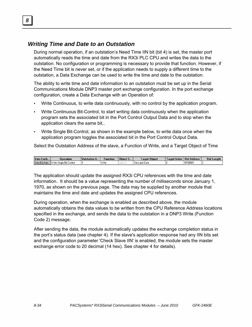
8-34 PACSystems* RX3iSerial Communications Modules – June 2010 GFK-2460E
8
Writing Time and Date to an Outstation During normal operation, if an outstation’s Need Time IIN bit (bit 4) is set, the master port automatically reads the time and date from the RX3i PLC CPU and writes the data to the outstation. No configuration or programming is necessary to provide that function. However, if the Need Time bit is never set, or if the application needs to supply a different time to the outstation, a Data Exchange can be used to write the time and date to the outstation.
The ability to write time and date information to an outstation must be set up in the Serial Communications Module DNP3 master port exchange configuration. In the port exchange configuration, create a Data Exchange with an Operation of:
Write Continuous, to write data continuously, with no control by the application program.
Write Continuous Bit-Control, to start writing data continuously when the application program sets the associated bit in the Port Control Output Data and to stop when the application clears the same bit..
Write Single Bit-Control, as shown in the example below, to write data once when the application program toggles the associated bit in the Port Control Output Data.
Select the Outstation Address of the slave, a Function of Write, and a Target Object of Time
The application should update the assigned RX3i CPU references with the time and date information. It should be a value representing the number of milliseconds since January 1, 1970, as shown on the previous page. The data may be supplied by another module that maintains the time and date and updates the assigned CPU references.
During operation, when the exchange is enabled as described above, the module automatically obtains the data values to be written from the CPU Reference Address locations specified in the exchange, and sends the data to the outstation in a DNP3 Write (Function Code 2) message.
After sending the data, the module automatically updates the exchange completion status in the port’s status data (see chapter 4). If the slave's application response had any IIN bits set and the configuration parameter 'Check Slave IIN' is enabled, the module sets the master exchange error code to 20 decimal (14 hex). See chapter 4 for details).

GFK-2460E Chapter 8 DNP3 Communications 8-35
8
Sending a Cold Restart Command to an Outstation The ability to send a Cold Restart command to an outstation must be set up in the Serial Communications Module DNP3 Master port exchange configuration. In the port exchange configuration, create a Data Exchange with an Operation of: Write Continuous, to write data continuously, with no control by the application program. Write Continuous Bit-Control, to start writing data continuously when the application
program sets the associated bit in the Port Control Output Data and to stop when the application clears the same bit.
Write Single Bit-Control, to write data once when the application program toggles the associated bit in the Port Control Output Data.
Select the Outstation Address of the slave, and a Function of Cold Restart. This exchange has no other selectable fields.
When the exchange executes, the module will issue DNP3 function code 13 to the outstation. The module responds with a Delay Measurement that provides the length of time the port will need to re-initialize. This is transparent to the RX3i application. After sending the data, the module automatically updates the exchange completion status in the port’s status data (see chapter 4). If the slave's application response had any IIN bits set and the configuration parameter 'Check Slave IIN' is enabled, the module sets the master exchange error code to 20 decimal (14 hex). See chapter 4 for details.

8-36 PACSystems* RX3iSerial Communications Modules – June 2010 GFK-2460E
8
Clearing the Device Restart IIN Bit in an Outstation Because most slaves do not store settings such as assignment of data classes that have been made by a DNP3 master, when an outstation is restarted, the DNP3 master must restore any settings it previously made. An outstation sets its Device Restart bit (index 7) to 1 when it restarts. By monitoring the outstation’s IIN data as described earlier, the DNP3 master port knows if the outstation has restarted. The master must clear the outstation’s Device Restart bit to 0, then restore any settings that have been lost when the outstation restarted.
15 14 13 12 11 10 9 8 7 6 5 4 3 2 1 0
MSB LSB
Device Restart
The ability to restart an outstation must be set up In the Serial Communications Module DNP3 master port exchange configuration. Create a Data Exchange with an Operation of: Write Continuous, to write data continuously, with no control by the application program. Write Continuous Bit-Control, to start writing data continuously when the application
program sets the associated bit in the Port Control Output Data and to stop when the application clears the same bit.
Write Single Bit-Control, to write data once when the application program toggles the associated bit in the Port Control Output Data.
Select the Outstation Address of the slave, and a Function of Write. As Target Object, choose Internal Indicators, and as Target Index select 7 (the offset of the Device Restart bit). Assign the data’s PLC CPU Reference Address. The length is always 1 word.
During operation, bit 7 of the CPU Reference Address location assigned in the Write exchange must be set to 0. When the exchange executes, the module obtains the data from the CPU Reference Address area and sends it to the outstation in a DNP3 Write (Function Code 2) message to clear the outstation’s reset bit.
After sending the data, the module automatically updates the exchange completion status in the port’s status data (see chapter 4). If the slave's application response had any IIN bits set and the configuration parameter 'Check Slave IIN' is enabled, the module sets the master exchange error code to 20 decimal.
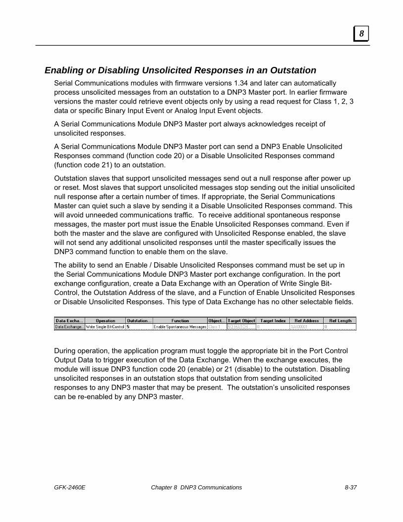
GFK-2460E Chapter 8 DNP3 Communications 8-37
8
Enabling or Disabling Unsolicited Responses in an Outstation Serial Communications modules with firmware versions 1.34 and later can automatically process unsolicited messages from an outstation to a DNP3 Master port. In earlier firmware versions the master could retrieve event objects only by using a read request for Class 1, 2, 3 data or specific Binary Input Event or Analog Input Event objects.
A Serial Communications Module DNP3 Master port always acknowledges receipt of unsolicited responses.
A Serial Communications Module DNP3 Master port can send a DNP3 Enable Unsolicited Responses command (function code 20) or a Disable Unsolicited Responses command (function code 21) to an outstation.
Outstation slaves that support unsolicited messages send out a null response after power up or reset. Most slaves that support unsolicited messages stop sending out the initial unsolicited null response after a certain number of times. If appropriate, the Serial Communications Master can quiet such a slave by sending it a Disable Unsolicited Responses command. This will avoid unneeded communications traffic. To receive additional spontaneous response messages, the master port must issue the Enable Unsolicited Responses command. Even if both the master and the slave are configured with Unsolicited Response enabled, the slave will not send any additional unsolicited responses until the master specifically issues the DNP3 command function to enable them on the slave.
The ability to send an Enable / Disable Unsolicited Responses command must be set up in the Serial Communications Module DNP3 Master port exchange configuration. In the port exchange configuration, create a Data Exchange with an Operation of Write Single Bit-Control, the Outstation Address of the slave, and a Function of Enable Unsolicited Responses or Disable Unsolicited Responses. This type of Data Exchange has no other selectable fields.
During operation, the application program must toggle the appropriate bit in the Port Control Output Data to trigger execution of the Data Exchange. When the exchange executes, the module will issue DNP3 function code 20 (enable) or 21 (disable) to the outstation. Disabling unsolicited responses in an outstation stops that outstation from sending unsolicited responses to any DNP3 master that may be present. The outstation’s unsolicited responses can be re-enabled by any DNP3 master.

8-38 PACSystems* RX3iSerial Communications Modules – June 2010 GFK-2460E
8
DNP3 Slave Operation of a Serial Communications Module Port
When a port on the Serial Communications Module is configured for DNP3 Slave operation, it provides the following features: Change event class assignable for each point from Master via Assign Class command Up to 25 events total object type (25 binary input events and 25 analog input events) Up to 64 configured Data Exchanges.
Each exchange can map of up to 2K bytes of contiguous CPU memory to a selected object type (for example, binary inputs). Configurable read and write access to specified references in RX3i CPU memory by
DNP3 master.

GFK-2460E Chapter 8 DNP3 Communications 8-39
8
Serial Communications Module DNP V3.0 Slave Device Profile DNP V3.00 DEVICE PROFILE DOCUMENT Vendor Name: GE Intelligent Platforms Device Name: PACSystems RX3i Serial Communications Module Highest DNP Level Supported:
For Requests: Level 1 For Responses: Level 1
Device Function: 변 Master
Slave Notable objects, functions, and/or qualifiers supported in addition to the Highest DNP Levels Supported (the complete list is described in the attached table): Will process read requests for most objects. Will process Assign Class function for the following objects:
Binary Input – Any Variation (Object 1, Variation 0) Analog Input – Any Variation (Object 30, Variation 0)
Maximum Data Link Frame Size (octets): Transmitted: 292 Received 292
Maximum Application Fragment Size (octets): Transmitted: 2048 Received: 2048
Maximum Data Link Re-tries: 변 None 변 Fixed at ____
Configurable from 0 to 255 via Link Maximum Retry Count field in port configuration
Maximum Application Layer Re-tries: None 변 Configurable
Requires Data Link Layer Confirmation: 변 Never 변 Always 변 Sometimes
Configurable as: Never, Only for multi-frame messages, or Always via Link Layer Confirmation mode bits in port configuration.
Requires Application Layer Confirmation: 변 Never 변 Always
When reporting Event Data When sending multi-fragment responses 변 Sometimes 변 Configurable
Timeouts while waiting for: Data Link Confirm: None Fixed at ____ Variable Configurable1 Complete Appl. Fragment: None Fixed at ____ Variable Configurable Application Confirm: None Fixed at ____ Variable Configurable 2 Complete Appl. Response: None Fixed at ____ Variable Configurable
Others: Select/Operate Arm Timeout, configurable via Select Before Operate Timeout field in port configuration.
Need Time Interval, configurable via Clock Valid Period field in port configuration. Note 1: Data Link Confirm Timeout configurable via Link Confirmation Timeout field. Note 2: Application Confirm Timeout configurable via Application Response Timeout field in port configuration.
Executes Control Operations: WRITE Binary Outputs Never Always Sometimes Configurable SELECT/OPERATE Never Always Sometimes Configurable DIRECT OPERATE Never Always Sometimes Configurable DIRECT OPERATE – NO ACK Never Always Sometimes Configurable Count > 1 Never Always Sometimes Configurable Pulse On Never Always Sometimes Configurable Pulse Off Never Always Sometimes Configurable Latch On Never Always Sometimes Configurable Latch Off Never Always Sometimes Configurable Queue Never Always Sometimes Configurable Clear Queue Never Always Sometimes Configurable

8-40 PACSystems* RX3iSerial Communications Modules – June 2010 GFK-2460E
8
DNP V3.00 DEVICE PROFILE DOCUMENT Reports Binary Input Events when no specific variation requested:
Never Only time-tagged Only non-time-tagged Configurable to send one or the other
Reports time-tagged Binary Input Events when no specific variation requested:
Never Binary Input Event With Time Binary Input Event With Relative Time Configurable
Sends Slave responses:
Never Configurable Only certain objects Sometimes ENABLE/DISABLE UNSOLICITED Function
codes supported
Sends Static Data in Slave responses:
Never When Device Restarts When Status Flags Change
No other options are permitted.
Default Counter Object/Variation:
No Counters Reported Configurable Default Object
Default Variation: Point-by-point list attached
Counters Roll Over at:
No Counters Reported Configurable 16 Bits 32 Bits Other Value: _____ Point-by-point list attached
Sends Multi-Fragment Responses: Yes No
Sequential File Transfer Support: Append File Mode Yes No Custom Status Code Strings Yes No Permissions Field Yes No File Events Assigned to Class Yes No File Events Poll Specifically Yes No Multiple Blocks in a Fragment Yes No Max Number of Files Open N/A

GFK-2460E Chapter 8 DNP3 Communications 8-41
8
Serial Communications Module DNP V3.0 Slave Implementation Table The following table identifies the object variations, function codes, and qualifiers supported by a Serial Communications Module as a DNP3 Slave. In the table, text shaded as 17, 28 indicates subset Level 2, 00, 01 indicates subset level 3 and 07, 08 indicates beyond level 3 functionality.
Object Request
(Slave will parse)
Response
(Slave will respond with)
Obj Var Description Func Codes (dec)
Qual Codes (hex)
Func Codes (dec)
Qual Codes (hex)
1 0 Binary Input – Any Variation
1 22
00,01 06 07,08 17,27,28
1 1
Binary Input 1 00,01 06 07,08 17, 27, 28
129 00, 01 17, 28
1 2
Binary Input with Status 1 00,01 06 07,08 17, 27, 28
129 00, 01 17, 28
2 0 Binary Input Event – Any Variation 1 06 07,08
2 1 Binary Input Event without Time 1 06 07,08
129
17, 28
2 2
Binary Input Event with Time 1 06 07,08
129 130
17, 28
2 3
Binary Input Event with Relative Time
1 06 07,08
129
17, 28
10 0 Binary Output – Any Variation 1 00, 01 06 07, 08 17, 27, 28
10 1
Binary Output 1 00, 01 06 07, 08 17, 27, 28
129 00, 01 17, 28
10 2
Binary Output Status 1 00, 01 06 07, 08 17, 27, 28
129 00, 01 17, 28
12 0 Control Relay Output Block 12 1 Control Relay Output Block 3
4 5 6
17, 28 129 echo of request
12 2 Pattern Control Block 12 3 Pattern Mask 20 0 Binary Counter – Any Variation 20 1 32-Bit Binary Counter (with Flag) 20 2 16-Bit Binary Counter (with Flag) 20 5 32-Bit Binary Counter without Flag 20 6 16-Bit Binary Counter without Flag

8-42 PACSystems* RX3iSerial Communications Modules – June 2010 GFK-2460E
8
Object Request
(Slave will parse)
Response
(Slave will respond with)
Obj Var Description Func Codes (dec)
Qual Codes (hex)
Func Codes (dec)
Qual Codes (hex)
21 0 Frozen Counter – Any Variation 21 1 32-Bit Frozen Counter (with Flag) 21 2 16-Bit Frozen Counter (with Flag) 21 5 32-Bit Frozen Counter with Time Of
Freeze
21 6
16-Bit Frozen Counter with Time Of Freeze
21 9 32-Bit Frozen Counter without Flag 21 10 16-Bit Frozen Counter without Flag 22 0 Counter Change Event – Any
Variation
22 1
32-Bit Counter Change Event without Time
22 2
16-Bit Counter Change Event without Time
22 5 32-Bit Counter Change Event with Time
22 6 16-Bit Counter Change Event with Time
23 0 Frozen Counter Event (Variation 0 is used to request default variation)
23 1 32-Bit Frozen Counter Event 23 2 16-Bit Frozen Counter Event 23 5 32-Bit Frozen Counter Event with
Time
23 6 16-Bit Frozen Counter Event with Time
30 0 Analog Input - Any Variation 1 22
00,01 06 07,08 17,27, 28
30 1 32-Bit Analog Input
1 00,01 06 07,08 17,27, 28
129 00, 01 17, 28
30 2
16-Bit Analog Input 1 00,01 06 07,08 17,27,28
129 00, 01 17, 28
30 3 32-Bit Analog Input without Flag
1 00,01 06 07,08 17,27, 28
129 00, 01 17, 28
30 4 16-Bit Analog Input without Flag 1 00,01 06 07,08 17,27, 28
129 00, 01 17, 28

GFK-2460E Chapter 8 DNP3 Communications 8-43
8
Object Request
(Slave will parse)
Response
(Slave will respond with)
Obj Var Description Func Codes (dec)
Qual Codes (hex)
Func Codes (dec)
Qual Codes (hex)
30 5 short floating point
1 00,01 06 07,08 17, 27, 28
129 00, 01 17, 28
30 6 long floating point
1 00,01 06 07,08 17,27, 28
129 00, 01 17, 28
32 0 Analog Change Event – Any Variation
1 06,07,08
32 1 32-Bit Analog Change Event without Time
1 06,07,08 129
17, 28
32 2
16-Bit Analog Change Event without Time
1 06,07,08 129 130
17, 28
32 3 32-Bit Analog Change Event with Time
1 06,07,08 129
17, 28
32 4 16-Bit Analog Change Event with Time
1 06,07,08 129 130
17, 28
32 5 Short Floating Point Analog Change Event without Time
1 06,07,08 129
17, 28
32 6 Long Floating Point Analog Change Event without Time
1 06,07,08 129
17, 28
32 7 Short Floating Point Analog Change Event with Time
1 06,07,08 129
17, 28
32 8 Long Floating Point Analog Change Event with Time
1 06,07,08 129 17, 28
34 0 Analog Input Deadband (Variation 0 is used to request default variation)
1
00, 01 06 07, 08 17, 28
1
00, 01 06 07, 08 17, 28
129 00, 01 17, 28
34 1 16 bit Analog Input Deadband
2 17, 28 1
00, 01 06 07, 08 17, 28
129 00, 01 17, 28
34 2 32 bit Analog Input Deadband
2 17, 28 1 00, 01
06 07, 08 17, 28
129 00, 01 17, 28
34 3 Short Floating Point Analog Input Deadband
2 17, 28 40 0 Analog Output Status (Variation 0 is
used to request default variation) 1
00,01 06 07,08 17,27, 28

8-44 PACSystems* RX3iSerial Communications Modules – June 2010 GFK-2460E
8
Object Request
(Slave will parse)
Response
(Slave will respond with)
Obj Var Description Func Codes (dec)
Qual Codes (hex)
Func Codes (dec)
Qual Codes (hex)
40 1 32-Bit Analog Output Status
1 00,01 06 07,08 17,27, 28
129 00, 01 17,28
40 2
16-Bit Analog Output Status 1 00,01 06 07,08 17,27, 28
129 00, 01 17,28
40 3 Short Floating Point Analog Output Status
1 00,01 06 07,08 17,27, 28
129 00, 01 17,28
40 4 Long Floating Point Analog Output Status
1 00,01 06 07,08 17,27,28
129 00, 01 17,28
41 0 Analog Output Block 41 1 32-Bit Analog Output Block
3 4 5 6
17, 28 129 echo of request
41 2 16-Bit Analog Output Block 3 4 5 6
17, 28 129 echo of request
41 3 Short Floating Point Analog Output Block
3 4 5 6
17, 27, 28 129 echo of request
41 4 Long Floating Point Analog Output Block
3 4 5 6
17, 27, 28 129 echo of request
50 0 Time and Date 1 07, 08 1
07(limited qty = 1)
129 07 50 1
Time and Date
2 07(limited qty = 1)
50 3 Time and Date Last Recorded Time
51 1 Time and Date CTO 129, 130
07(limited qty) (qty = 1)
51 2 Unsynchronized Time and Date CTO 129, 130
07(limited qty) (qty = 1)
52 1 Time Delay Coarse 129 07(limited qty) (qty = 1)
52 2 Time Delay Fine 129 07(limited qty) (qty = 1)
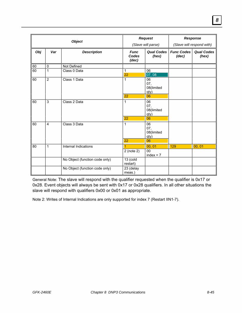
GFK-2460E Chapter 8 DNP3 Communications 8-45
8
Object Request
(Slave will parse)
Response
(Slave will respond with)
Obj Var Description Func Codes (dec)
Qual Codes (hex)
Func Codes (dec)
Qual Codes (hex)
60 0 Not Defined 60 1 Class 0 Data 1
22 06 07, 08
1
06 07, 08(limited qty)
60 2 Class 1 Data
22 06
1
06 07, 08(limited qty)
60 3 Class 2 Data
22 06
1 06 07, 08(limited qty)
60 4 Class 3 Data
22 06
1 00, 01 129 00, 01 80 1 Internal Indications 2 (note 2) 00
index = 7
No Object (function code only) 13 (cold restart)
No Object (function code only) 23 (delay meas.)
General Note: The slave will respond with the qualifier requested when the qualifier is 0x17 or 0x28. Event objects will always be sent with 0x17 or 0x28 qualifiers. In all other situations the slave will respond with qualifiers 0x00 or 0x01 as appropriate.
Note 2: Writes of Internal Indications are only supported for index 7 (Restart IIN1-7).

8-46 PACSystems* RX3iSerial Communications Modules – June 2010 GFK-2460E
8
Serial Communications Module DNP3 Slave Point Lists
Binary Input Points The default binary input event buffer size is set to allow 25 events.
Binary Input Points Static (Steady-State) Object Number: 1 Change Event Object Number: 2 Static Variation reported when variation 0 requested: 1 (Binary Input 2 without status) Change Event Variation reported when variation 0 requested: 2 (Binary Input Event with Time)
Point Index
Name/Description Default Change Event Assigned Class (1, 2, 3 or none)
0-16,383 (determined by implementation) (determined by implementation)

GFK-2460E Chapter 8 DNP3 Communications 8-47
8
Binary Output Status Points and Control Relay Output Blocks Binary Output Status Points
Object Number: 10 Default Variation reported when variation 0 requested: 2 (Binary Output Status)
Control Relay Output Blocks Object Number: 12
Point Index
Name/Description Supported Control Relay Output Block Fields
0-16,383 (determined by implementation) All
Binary Output Status points are not often polled by DNP3 masters. It is recommended that Binary Output Status points be used to represent the most recent DNP commanded value for the corresponding Control Relay Output Block point. Because many Control Relay Output Block points are controlled through pulse mechanisms, the value of the output status may not be meaningful. Binary Output Status points are not recommended for inclusion in class 0 polls.
Instead, the actual status values of Control Relay Output Block points should be looped around and mapped as Binary Inputs. The actual status value, as opposed to the commanded status value, is the value of the actuated control. For example, a DNP control command may be blocked through hardware or software mechanisms; in that case, the actual status value would indicate the control failed because of the blocking. Looping Control Relay Output Block actual status values as Binary Inputs allows: Actual status values to be included in class 0 polls. Change event reporting of the actual status. Reporting of time-based information associated with controls, including any delays before
controls are actuated, and any durations if the controls are pulsed. The default select/control buffer size is large enough to hold one of the largest possible select requests.

8-48 PACSystems* RX3iSerial Communications Modules – June 2010 GFK-2460E
8
Analog Inputs Analog Inputs
Static (Steady-State) Object Number: 30 Change Event Object Number: 32 Static Variation reported when variation 0 requested: 2 (16-Bit Analog Input ) Change Event Variation reported when variation 0 requested: 2 (16-Bit Analog Change Event w/o Time) or 4 (16‐Bit Analog Change Event with Time) when so configured
Point Index
Name/Description Default Deadband Default Change Event Assigned Class (1, 2, 3 or none)
0-1,023 (determined by implementation)
(determined by implementation)
(determined by implementation)
The 16-bit and 32-bit variations of Analog Inputs, Analog Output Control Blocks, and Analog Output Status are transmitted as signed numbers.
The “Default Deadband” and “Default Change Event Assigned Class” columns indicate the absolute amount by which the point must change before an analog change event will be generated, and once generated in which class poll (1, 2, 3, or none) the change event will be reported.
The default analog input event buffer size is set to 25.
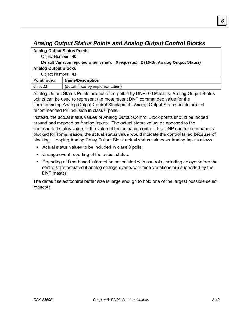
GFK-2460E Chapter 8 DNP3 Communications 8-49
8
Analog Output Status Points and Analog Output Control Blocks Analog Output Status Points Object Number: 40 Default Variation reported when variation 0 requested: 2 (16-Bit Analog Output Status) Analog Output Blocks Object Number: 41 Point Index Name/Description 0-1,023 (determined by implementation)
Analog Output Status Points are not often polled by DNP 3.0 Masters. Analog Output Status points can be used to represent the most recent DNP commanded value for the corresponding Analog Output Control Block point. Analog Output Status points are not recommended for inclusion in class 0 polls. Instead, the actual status values of Analog Output Control Block points should be looped around and mapped as Analog Inputs. The actual status value, as opposed to the commanded status value, is the value of the actuated control. If a DNP control command is blocked for some reason, the actual status value would indicate the control failed because of blocking. Looping Analog Relay Output Block actual status values as Analog Inputs allows: Actual status values to be included in class 0 polls, Change event reporting of the actual status. Reporting of time-based information associated with controls, including delays before the
controls are actuated if analog change events with time variations are supported by the DNP master.
The default select/control buffer size is large enough to hold one of the largest possible select requests.

8-50 PACSystems* RX3iSerial Communications Modules – June 2010 GFK-2460E
8
Implementing DNP3 Slave Functions Data Exchanges define DNP3 communications for the slave port, and map DNP3 data to CPU reference addresses. Up to 64 Data Exchanges can be configured for each port. Some example Data Exchanges are shown below as they appear on the configuration screen.
For this DNP3 Master
Operation PLC Access Target Object
Binary Input (Object 1, variation 1) Binary Output Status (Object 10, variation 2) Analog Input (Object 30, variation 3, 4, 5, or 6)
Read binary input, analog input , or binary status data from a range of PLC memory.
Read Only; only one Exchange for each Target Object Group
Analog Output Status (Object 40, var. 1, 2, 3, or 4)
Control Relay Block (Object 12, variation 1)
Write static discrete or analog output data to a specified range of PLC memory.
Write Only; only one Exchange for each Target Object Group Analog Output Block (Object
41, var. 1, 2 .3, or 4)
Read or write analog deadband values from a location in PLC memory.
Read / Write; only one Exchange for each Target Object Group
Analog Input Deadband (Object 34, var. 1, 2, or 3)
Monitor a class of one or more data points in the RX3i PLC CPU for change events.
Create two (or more) Data Exchanges with these Access Types: 1. Read Only: define the points to be
monitored for change. 2. Write Single Bit-Control or Write
Continuous Bit-Control: set up the CPU’s reporting of some or all of the defined change events to the module.
3. (optional) Read/Write exchange for analog deadband value from master.
Binary Input (Object 1 variation 1) Analog Input (Object 30 variation 1 2, 5, or 6)

GFK-2460E Chapter 8 DNP3 Communications 8-51
8
Processing of Data Exchanges During Operation The DNP3 Slave port responds to master requests as they are received.
1. If the port receives a Delay Measurement function, the module returns that value to the master in a DNP3 Slave Response. No programming or Data Exchange configuration is required for this operation.
2. If the port receives a Cold Restart function, the module responds with a 'Delay Measurement' that contains the duration of time the port will need to re-initialize. No programming or Data Exchange configuration is required for this operation.
3. If the port receives an Assign Class function, the module processes the request for the given data point(s), and stores the assignment in its internal memory. No programming or Data Exchange configuration is required for this operation.
4. For all other requests from the DNP3 master, the module scans the Data Exchanges that have been configured for the DNP3 Slave port, from 1 to 64. The module compares the request against the configured Data Exchanges until a match containing the object is found.
The first match found while scanning from exchange 1 to 64 is always used. That means for PLC Access Types Read Only, Read / Write and Write Only, only one Data Exchange should be defined per DNP3 Object type (for example, Object 30, variation 1, 2, 5, or 6). If additional exchanges of the same type were defined, they would be ignored by the module.
If the object is not found, the module sets the Object Unknown bit (bit 9) in its IIN data and returns that to the master.
If the object’s function is a valid Select (DNP3 function code 3), the module buffers the Select and records the time. The specified data point is then in an armed state. A subsequent Operate (function code 4) will be honored for this data point.
If the object’s function is a valid Operate, the module checks its Select buffer for a Select for the same object. If none is present, the module sets its IIN bits to indicate the error and returns the IN bits to the master in the response to the command.
The module checks the time of the Select. If the Select Before Operate Timeout value is not exceeded, it executes the Operate.
The module updates the data in the CPU memory Reference Address assigned in the Data Exchange.
The module clears the Select from its internal Select buffer.

8-52 PACSystems* RX3iSerial Communications Modules – June 2010 GFK-2460E
8
If the command on the object is a valid Read (DNP3 function code 1), the module automatically obtains the data from its assigned CPU Reference Address location and returns the value to the master in a DNP3 slave response.
If the command on the object is a valid Direct Operate (DNP3 function code 5 or 6) or Write (DNP3 function code 2), the module automatically updates the data point Reference Address in CPU memory.
5. The module updates the port’s Exchange Completion status in the CPU. The module is then ready for the next master request.
6. The application logic can optionally monitor the Port Input Status Exchange Error Report bits and the DNP3 Slave Port Status. These bits report errors that can occur if a DNP3 master is not correctly configured to interact with the Serial Communications Module slave port. For example, the master may request data points that are not defined, or issue unsupported functions.

GFK-2460E Chapter 8 DNP3 Communications 8-53
8
Creating Change Events for a DNP3 Slave Port A Serial Communications Module port configured as a DNP3 slave supports the DNP3 Slave response function, which allows slaves to report Change Event data to the master without the master first requesting the data. It is possible to define and implement Change Events for data objects for a DNP3 Slave port as described below. The application must evaluate the data being exchanged, and if it determines a change event should be created, it must initiate the creation by setting the bit associated with the exchange.
Configuration for Monitoring and Reporting Change Events The ability to read change events for RX3i CPU points must be set up in the Serial Communications Module DNP3 slave port configuration.
1. Define a group of contiguous static data points to be monitored for change. Create a Data Exchange with a PLC Access type of Read Only. Specify the type of binary or analog input data to be monitored for change (by the PLC application program logic).
In the example below, the Read Only exchange sets up inputs %I00001 to %I00032 as static data points to be monitored for change.
2. Set up the CPU’s reporting of some or all of the defined change events to the Serial Communications module. Create one or more of the following Data Exchange types: Write Single Bit-Control or Write Continuous Bit-Control.
In each exchange, set up one or more of the points that are being monitored for reporting changes to the module. In these exchanges, the Object Class field defines the powerup default class assignment for the points. This can be changed by the master using an Assign Class function. The Target Index field specifies the offset within the specified group of data where reporting to the CPU should start. If the Target Index is 0, reporting is enabled for all points in the configured range.
In same example, below, two Write Single Bit-Control exchanges are set up. The first Write Single Bit-Control exchange reports changes to inputs %I00001 through %I00016 as event objects. The second Write Single Bit-Control exchange in this example reports changes to inputs %I00017 through %I00032 as Class 1 data.

8-54 PACSystems* RX3iSerial Communications Modules – June 2010 GFK-2460E
8
Configuration to Use Analog Input Deadband Values from the DNP3 Master In evaluating analog input data for changes, the application program can compare static analog values against predefined deadband values. A deadband value can be internal to the PLC CPU, or supplied by the DNP3 Master. If the master will read or write an analog deadband value, create an additional Data Exchange with the Target Object being the type of analog input deadband needed, as shown in this example.
Application Logic for Change Events During operation, the application logic in the RX3i CPU must check for changes to the static points that are being monitored. In the case of analog inputs, predefined deadband values can be used as references to determine whether a change event has occurred.
When RX3i CPU detects a change in the static data, the application logic must trigger the write-type Data Exchange to report the change, by setting the bit associated with the exchange in the Port Output Control data. For example, to trigger Data Exchange Number 4, the application logic would set or toggle Port Control Output bit #4.
When the application logic triggers the bit-controlled exchange, the Serial Communications module automatically reads the changed data from the configured PLC CPU Reference Address locations and stores the data in its internal Change Event queue. The module automatically creates a DNP3 change event for each point in the data based on the information provided in the Data Exchange as well as master assigned class information stored by the module. For example, the module stores binary input changes as Binary Input with Change data (Object 2 variation 0). The module stores data assigned to Class 1 as Object 60, variation 2.
After completing the exchange, the Serial Communications Module updates the exchange completion status in the Port Status Data. The application logic can check the Port Status Exchange Error Report bits (see chapter 4) and read the Error Status, if valid, for the given exchange from the Port Input Status data. If an error has occurred, the error code 0x14 is generated. The application may be set up to attempt to clear the error code and create the change event again.
Unsolicited Responses When unsolicited responses are enabled, the slave port manages the delay and retries of transmitting the change event as an unsolicited response to the address defined in that port's configuration. If the Max Unsolicited Response Delay is zero, the slave immediately sends an unsolicited response. If the value is larger than zero, it waits until the timeout expires, or until five events are waiting to be sent.

GFK-2460E Chapter 8 DNP3 Communications 8-55
8
DNP3 Master Reading Static or Event Data During operation, the DNP3 Master can read static data, class data, and change event data by sending the module a DNP3 a Read function with the appropriate data type. If the master requests a static data type, the module obtains the requested data from the PLC CPU and automatically reports it back to the DNP3 Master.
If the master requests class or event data, that data is read directly from the module’s internal Change Event buffer. A change event stays in the module’s internal Change Event buffer until the module receives a request to read the data from the Master. The data can be read as either Class data or as Change Event data. A change event can only be read once. After the master reads the data and confirms that it has received the data, the module removes the event from its Change Event buffer. The module can store up to 25 binary input events and 25 analog input change events. If either the binary or analog Change Event buffer overflows, the Serial Communications Module removes the oldest change from that buffer and sets the buffer overflow bit in its IIN data. The master should poll for change events often enough that change events are not lost. If Change Events have been lost, the master should perform an integrity scan to obtain the current state of all data points on the Serial Communications Module slave port.

8-56 PACSystems* RX3iSerial Communications Modules – June 2010 GFK-2460E
8
Reporting Commanded Values Back to the Master The DNP3 Master can write binary or analog output data to the RX3i CPU, then read back the contents of the same references to determine whether the commanded output values are present in the assigned PLC CPU references.
The ability to report commanded values back to the DNP3 Master requires setting up two associated Data Exchanges in the Serial Communications Module DNP3 slave port configuration.
1. Create a Write Only exchange that defines the Target Object type (Control Relay Block for discrete outputs or one of the Analog Output Block types for analog outputs) and RX3i CPU Reference Address location of the output data that will be written by the DNP3 master.
As explained in chapter 3, only one Write Only Data Exchange can be set up per Target Object Type (including all variations of that object type). For example, the slave port can be configured with a Write Only exchange having a Target Object of 16-Bit Analog Output Block and another Write Only exchange having a Target Object of Control Relay Block. However, the slave port should NOT be configured for two Write Only exchanges having a Target Object of Control Relay Block, even if different CPU Reference Addresses are assigned to the data. Please refer to the DNP3 Slave Configuration section of chapter 3 for details.
2. Create a Read Only exchange with a Target Object of Binary Output Status or analog output status (corresponding to the Target Object type set up in the Write Only exchange). As with the Write Only exchange, there can only be one Read Only exchange per Target Object Type.
Assign the same Reference Address and Reference Length as the Write Only exchange.
This second exchange is needed to read the output status because Binary Output Status data is not reported back to a master in a response to a class 0 poll.
During operation, the Master will write the output data to the DNP3 slave port. The module will automatically write the data to the configured Reference Addresses in the RX3i CPU. When the port subsequently receives a DNP3 Read function requesting Output Status data of the specified Target Object type, the module will automatically read the contents of the requested references within the configured range, and return the data to the master as the specified DNP3 Object and Variation.
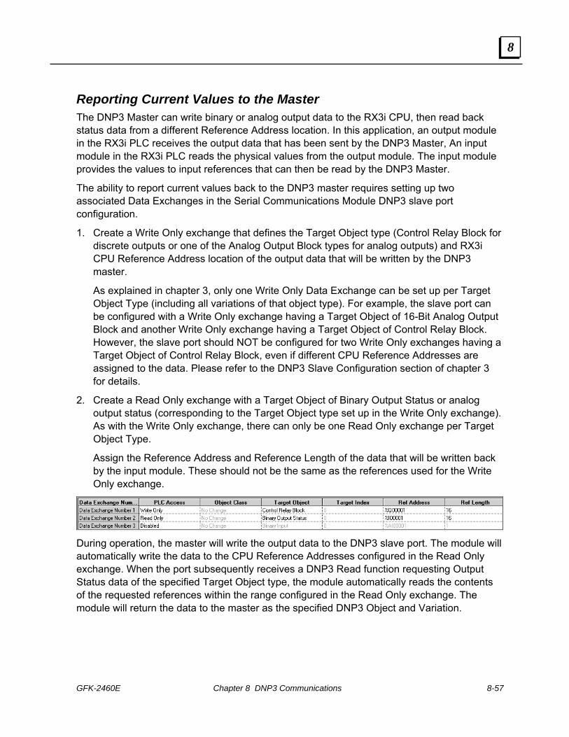
GFK-2460E Chapter 8 DNP3 Communications 8-57
8
Reporting Current Values to the Master The DNP3 Master can write binary or analog output data to the RX3i CPU, then read back status data from a different Reference Address location. In this application, an output module in the RX3i PLC receives the output data that has been sent by the DNP3 Master, An input module in the RX3i PLC reads the physical values from the output module. The input module provides the values to input references that can then be read by the DNP3 Master.
The ability to report current values back to the DNP3 master requires setting up two associated Data Exchanges in the Serial Communications Module DNP3 slave port configuration.
1. Create a Write Only exchange that defines the Target Object type (Control Relay Block for discrete outputs or one of the Analog Output Block types for analog outputs) and RX3i CPU Reference Address location of the output data that will be written by the DNP3 master.
As explained in chapter 3, only one Write Only Data Exchange can be set up per Target Object Type (including all variations of that object type). For example, the slave port can be configured with a Write Only exchange having a Target Object of 16-Bit Analog Output Block and another Write Only exchange having a Target Object of Control Relay Block. However, the slave port should NOT be configured for two Write Only exchanges having a Target Object of Control Relay Block, even if different CPU Reference Addresses are assigned to the data. Please refer to the DNP3 Slave Configuration section of chapter 3 for details.
2. Create a Read Only exchange with a Target Object of Binary Output Status or analog output status (corresponding to the Target Object type set up in the Write Only exchange). As with the Write Only exchange, there can only be one Read Only exchange per Target Object Type.
Assign the Reference Address and Reference Length of the data that will be written back by the input module. These should not be the same as the references used for the Write Only exchange.
During operation, the master will write the output data to the DNP3 slave port. The module will automatically write the data to the CPU Reference Addresses configured in the Read Only exchange. When the port subsequently receives a DNP3 Read function requesting Output Status data of the specified Target Object type, the module automatically reads the contents of the requested references within the range configured in the Read Only exchange. The module will return the data to the master as the specified DNP3 Object and Variation.

8-58 PACSystems* RX3iSerial Communications Modules – June 2010 GFK-2460E
8
Example 1: Exchanges for a DNP3 Slave Port As a DNP3 slave, the Serial Communications Module provides flexible access to the RX3i CPU. In the simple example below, the DNP3 master writes one binary output and one analog output data to the RX3i CPU, then reads back the contents of the same references to determine whether the commanded output values are present in the assigned PLC CPU references. This example also includes two exchanges that the application logic can use to create change events for one binary input and one analog input.
Data Exchange 1: allows the DNP3 master to read one Binary Input from CPU Reference Address %I00001. This input is assigned to Class 1 in Data Exchange 7. Data Exchange 2: allows the DNP3 master to write 1 bit of Control Relay Block (binary output) data to CPU Reference Address %Q00001. Data Exchange 3: allows the DNP3 master to read the commanded value (Binary Output Status) of the data it has previously written to %Q00001. Data Exchange 4: allows the DNP3 master to read the value of one analog input from CPU Reference Address %AI0001. Data Exchange 5: allows the DNP3 master to write one 16-Bit Analog Output to CPU Reference Address %AQ0001. Data Exchange 6: allows the DNP3 master to read the commanded value (16-Bit Analog Output Status) of the data it has previously written to %AQ0001. Data Exchange 7: assigns the Binary Input point at %I00001 to Object Class 1 (the master can change this at run time). If the point changes, the application logic in the RX3i CPU must trigger Data Exchange 7 by setting bit 7 in the Port Output Control data (see chapter 4 for more information). The Serial Communications module then automatically reads the changed data from %I00001 and writes the data to its internal Change Event queue where it can be read by the master. Data Exchange 8: assigns the 16-Bit Analog Input value at %AI0001 to Object Class 2 (the master can change this at run time) (the master can change this at run time). If the value changes, the application logic in the RX3i CPU must trigger Data Exchange 8 by setting bit 8 in the Port Output Control data (see chapter 4 for more information). The Serial Communications module then automatically reads the changed data from %I00001 and writes the data to its internal Change Event queue where it can be read by the master.

GFK-2460E Chapter 8 DNP3 Communications 8-59
8
Example 2: Data Exchanges for Outputs Mapped to Inputs In this example, the commanded values are mapped back directly as inputs. This allows the application logic to create change events when a commanded value is detected as having been processed. This slave only has a binary output and an analog output. The ‘inputs’ are really the currently-commanded values to those outputs. In this example application, an output module uses the values stored in reference memory at %Q0001 and %AQ0001 to drive physical outputs to the commanded values.
Binary Output Status Points are not often polled by DNP 3.0 Masters. It is recommended that binary or analog output status points represent the most recent DNP3 commanded value for the corresponding control output points. Neither Binary Output Status points nor Analog Output Status points are recommended for inclusion in class 0 polls.
As an alternative, actual status values (the values of the actuated controls as opposed to the commanded status values), can be looped around and mapped as inputs. Looping output actual status values back as inputs allows:
Actual status data to be included in class 0 polls,
Change event reporting of the actual status information.
Reporting of time-based information associated with controls, including any delays before controls are actuated, and any durations if controls are pulsed.


GFK-2460E 9-1
Serial Protocol Language (SPL)
This chapter describes the Serial Protocol Language feature of PACSystems RX3i Serial Communications Modules. Serial Protocol Language (SPL) is a simple, flexible scripting language for writing custom serial protocols.
SPL Overview Serial Protocol Language Description Defining User Variables Statements for Script Control: GOTO, FOR-TO-NEXT, IF-THEN-ELSE-ENDIF, GOSUB-
RETURN, STOP Error Handling in the SPL Script
Global Variable: ERROR Statements and Global Variable for CPU Data Exchanges
Statements: EXNEXT, EXSTAT, EXREAD, EXWRITE Global Variable: EXCHANGE
Statements for Serial Communications: GETB, PUTB Statements to Calculate Checksums: BCC, CRC Mathematical and Logical Operators: AND, OR, XOR, MOD Statements for ASCII Conversions: ASCTOVAL, VALTOASC Statements to Read Time: TIMER, ELAPSED Downloading an SPL Script to the Port Using the Command Line Interface
Commands: RUN, STEP, CONT, LIST Printing from the SPL Script or Command Line Interface Sample SPL Script In the sample SPL logic in this chapter:
Parameters in […] are required Parameters in <…> are optional
Chapter
9

9-2 PACSystems* RX3iSerial Communications Modules – June 2010 GFK-2460E
9
SPL Overview Serial Protocol Language (SPL), which is similar to BASIC, can be used to easily and quickly create a custom protocol for a PACSystems RX3i Serial Communications Module.
The custom protocol can be run concurrently with the module’s built-in MODBUS, CCM, or Serial I/O protocol. (DNP3 protocol, which is described in chapter 8, cannot be used at the same time as any other protocol.) An SPL script running on one port with the other ports disabled will execute faster than it would with SPL scripts or protocols also running on the other ports. For example, the time it takes to execute a FOR-NEXT loop on a given port will vary based on the execution of the protocols on the other ports.
Configuring a Port for SPL During module configuration, any port can be set up for SPL operation. Port configuration for SPL is similar to configuration for one of the module’s built-in protocols. The serial communications parameters for the port must be specified, and data exchanges must be set up. The data exchanges allow the Serial Communications Module to read and write CPU data. Chapter 3 describes the steps for configuring data exchanges.
Creating an SPL Script Each port on the module that will use SPL protocol must receive an SPL script from the CPU. The SPL script is an ASCII file that can be created and edited using any text editing program. The completed file, which must have the filename extension .spl, is easily added to the RX3i project as described later in this chapter. The CPU automatically downloads the SPL script to the module along with the port configuration.

GFK-2460E Chapter 9 Serial Protocol Language (SPL) 9-3
9
Operation of the SPL Script The statements, operators, global variables and other elements of the Serial Protocol Language are used for reading and writing serial port data, and for exchanging that data with the RX3i CPU in the appropriate format.
For Controlled Exchanges (controlled by the PLC CPU), EXNEXT statements in the SPL script read data from the PLC CPU using configured write exchanges, or write data to the CPU using configured read exchanges. The SPL script will perform any data manipulation necessary (ASCII conversion, logical operations, math operations etc…). Note that Controlled Exchanges are controlled by the CPU. They read data from, or write data to, the module from the CPU’s perspective.
RX3i CPU
CMM Module
Serial Device
Write Exchange
Read Exchange
RX3i Backplane
For Validated Exchanges (controlled by the CMM Module), EXREAD statements in the SPL script read data from the PLC CPU using configured Read Only or Read/Write exchanges EXWRITE statements in the SPL script write data to the CPU using configured Read/Write or Write Only exchanges. The SPL script will perform any data manipulation necessary (ASCII conversion, logical operations, math operations etc…). Note that Validated Exchanges are controlled by the Serial Communications module. They read data from, or write data to, the CPU from the module’s perspective.
RX3i CPU
CMM Module
Serial Device
Read Only
Write Only
RX3i Backplane
Read / Write

9-4 PACSystems* RX3iSerial Communications Modules – June 2010 GFK-2460E
9
To communicate on the serial bus, the SPL script can either transmit the data using a PUTB statement, or receive data using a GETB statement. The SPL script will perform error-handling, and provide error information to the PLC CPU in its status data, as described below.
RX3i CPU
CMM Module
Serial Device
PUTB Statement
GETB Statement
RX3i Backplane
Exchanging Status and Control Data with the PLC CPU In addition to reading and writing port data using the configured data exchanges, the Serial Communications Module automatically reads port control data from the CPU and writes port status data to the CPU using the port’s configured input and output reference addresses. This data is transferred between the R3i CPU and the Serial Communications Module during each I/O scan of the CPU.
The application program in the PLC CPU can use the port’s Output Control Data to: Enable individual data reads and writes with the port by setting their associated data
exchange control bits. Acknowledge and clear port errors. Reset the SPL script by setting the Port Reset bit to 1. Optionally write custom information to the port using bytes 12-16 of the Output Control
Data. The meaning of this data must be defined by the user. It is accessible within the SPL script using the global variable IOCTRL.
The application program in the PLC CPU can use the Input Status Data to: Monitor the exchange response report bits, exchange error report bits, the port status, the
exchange error status, and the SPL port status in the port’s Input Status Data. Optionally, use the information from the port in bytes 20-25. The meaning of this data is
defined by the user. If is accessible within the SPL script using the global variable IOSTAT.
Chapter 4 provides a detailed description of the content of the status and control data.

GFK-2460E Chapter 9 Serial Protocol Language (SPL) 9-5
9
SPL Summary This section is a summary of configuration, CPU operations, and script operations for Serial Protocol Language scripts.
Task How to Implement Declare a User Variable SPL: Use the SPL statement DIM [variablename]
INTEGER, or DIM [variablename] ARRAY Jump to label in script SPL: GOTO statement Interative loop in script SPL: FOR-TO-NEXT statements Conditional execution of code SPL: IF-THEN-<ELSE>-ENDIF statements Jump to label then return to same place
SPL: GOSUB-RETURN statements
Calculate checksum SPL: BCC statement or CRC statement Perform Mathematical and Logical operation on data
SPL: <, >, =, <=, >=, < >, +, -, *, /, AND, OR, XOR, MOD.
Convert ASCII to decimal or hex SPL: ASCTOVAL statement Convert decimal or hex to ASCII SPL: VALTOASC statement Read timer SPL: TIMER statement Read elapsed time SPL: ELAPSED statement Use SPL Command Line Interface Set port’s SPL configuration to enabled Assign Command Line Interface port
Choose CLI port in the module configuration
Set up SPL script to auto-run Enable Auto-Run Program in SPL configuration Stop script and return to Command Interface Port
SPL: STOP statement in SPL script
Test for errors in SPL script SPL: ERROR global variable with user variable Monitor error status CPU: Check Input Status byte 26 Acknowledge error CPU: Set Output Status bit 65 Clear all errors CPU: Set Output Status bit 66 Start SPL script from beginning RUN command from Command Line Interface Reset port and restart SPL script CPU: Set Output Status bit 67 Step through script to debug STEP command from Command Line Interface Start SPL script from current line CONT command from Command Line Interface Display script and statistics LIST command from Command Line Interface Print to Command Line Interface PRINT statement in SPL script or from Command Line
Interface Print to PLC CPU PRINT statement in SPL script or from Command Line
Interface . (Print exchange must be configured). Read or write CPU data using next Controlled data exchange
Configure data changes with Exchange Type of Controlled

9-6 PACSystems* RX3iSerial Communications Modules – June 2010 GFK-2460E
9
Task How to Implement CPU: Set Output Status bits 1-64 to trigger bit-controlled data exchanges
SPL: EXNEXT statement in conjunction with EXCHANGE global variable followed by EXSTAT statement. Configure data exchanges with Exchange Type of Validated with Read Only or Read/Write Operation
Read CPU data under CPU control using Validated data exchange
SPL: EXREAD statement in conjunction with EXCHANGE global variable Configure data exchanges with Exchange Type of Validated with Read/Write or Write Only Operation
Write data to CPU under SPL script control using Validated data exchange SPL: EXWRITE statement in conjunction with
EXCHANGE global variable Monitor status of data exchanges with port
CPU: Check Input Status bits 1-64
Monitor error status of data exchanges with the port
CPU: Check Input Status bits 65-128
Select exchange to report errors CPU: Write exchange number to Output Status byte 10 Set up port data rate Serial port configuration Set up port data bits Serial port configuration Set up communications parity Serial port configuration Set up communications stop bits Serial port configuration Set up port type Serial port configuration Set up flow control Serial port configuration Monitor port configuration status CPU: Check Input Status bits 129-144 Set value of RTS line SPL: SERIAL global variable Obtain value of CTS line SPL: SERIAL global variable Check for idle/transmitting SPL: SERIAL global variable Transmit serial data SPL: PUTB statement Clear transmit buffer SPL: SERIAL global variable Receive serial data SPL: GETB statement Clear receive buffer SPL: SERIAL global variable Monitor serial port status CPU: Check Input Status byte 19 Check overrun and receive errors SPL: SERIAL global variable
SPL: Read from IOCTRL global variable Transfer up to 5 bytes of data to the module CPU: Write to IOCTRL using Output Status bytes 12-16.
SPL: Write to IOSTAT global variable Read up to 5 bytes of data from the module CPU: Monitor IOSTAT using input Status byte 20-24

GFK-2460E Chapter 9 Serial Protocol Language (SPL) 9-7
9
Serial Protocol Language Description Serial Protocol Language defines a set of operators, reserved symbols, and commands that can be used in programs to control serial operations.
Reserved Symbols Symbol Description
! <exclamation> Comment or remark designator. Anything after this character until end of line is ignored.
: <colon> Label designator ( :jumptohere )
. <period> Variable subscript reference ( i.e. variable.2 = 5 )
“ ” <quote pair> used to define strings constant for PRINT statement
( ) <Parenthesis pair> used to force precedence
‘ ’ Single quote used to specify single ASCII character (i.e. msg.5 = ‘Q’ )
& Used to concatenate arguments for PRINT statement
Syntax rules and requirements All syntax must be separated by a space.
Syntax must be in uppercase.
Function calls cannot be embedded in print or control statements
One statement per line (not including comments )
Maximum of three operators per expression.

9-8 PACSystems* RX3iSerial Communications Modules – June 2010 GFK-2460E
9
SPL Statements An SPL script can include the following statements:
Statements For Declaring Variables and Data Types DIM Declare a variable ( requires type: integer, array ) ARRAY Data type declaration INTEGER Data type declaration ( 32 bit signed )
Statements For Exchanging Data with the PLC CPU EXNEXT Next exchange to process if a controlled exchange was
triggered. EXSTAT Sets the exchange status. Required to be called after an
EXNEXT. EXREAD Reads data from CPU memory via a Validated exchange. EXWRITE Writes data to CPU reference memory via a Validated
exchange. Statements For Exchanging Data with the Serial Port
GETB Returns up to N char(s) from serial port PUTB Sends N char(s) to serial port
Statements For Controlling Logic Execution GOTO Jump to new location in program and begins execution FOR – TO – NEXT Iterative loop control IF - THEN - ELSE - ENDIF
Conditional control statement ( ELSE not required )
GOSUB – RETURN Jump to subroutine and return STOP Causes program to stop and returns focus to Command
Line Interface terminal Statements For Logical Operations
AND Bitwise AND of integer or array element OR Bitwise OR of integer or array element XOR Bitwise XOR of integer or array element MOD Returns remainder of division
Statements For Converting ASCII ASCTOVAL Converts ASCII characters to a value VALTOASC Converts value to ASCII characters
Statements For Calculating Checksums BCC Calculate BCC of data array( Same as serial I/O) CRC Calculate 16 bit CRC of data array (Same as serial I/O)
Statements For Reading the Time TIMER Returns the port’s mS timer value. Timer set to 0 on RUN. ELAPSED Returns elapsed mS (pass timestamp arg for calc )

GFK-2460E Chapter 9 Serial Protocol Language (SPL) 9-9
9
Global Variables
Global variables are an important part of an SPL script. Global variables for SPL are listed below and described in detail in the referenced sections. Global variables do not need to be declared using DIM statements in the script.
ERROR Provides status information about the SPL script, which is accessible to the script and mirrored in the port’s PLC CPU reference addresses. See Error Handling.
EXCHANGE Used in conjunction with the EXNEXT, EXREAD, and EXWRITE commands, which are used to read and write data in PLC CPU memory. See Exchanging Data with the PLC CPU.
IOCTRL A 5-byte array that represents part of the port’s configured Output Control Data CPU memory references. Can optionally be used to provide CPU control of protocol features. See Application Program Interface to the Serial Protocol.
IOSTAT A 5-byte array that represents part of the port’s configured Input Status Data CPU memory references. Can optionally be used to report protocol information to the PLC CPU. See Application Program Interface to the Serial Protocol.
SERIAL Provides a set of status and transaction information about serial communications (between the port and an external LAN). The SERIAL global variable is used by the GETB and PUTB commands in the SPL script. See Serial Data.

9-10 PACSystems* RX3iSerial Communications Modules – June 2010 GFK-2460E
9
Defining User Variables In addition to the global variables that are an integral part of SPL, user variables will be required in the script. All variables have global scope per port. They can be read or modified at any point in the program.
All variables must be declared as type INTEGER or type ARRAY using the DIM statement before they can be used. Each variable can be declared only once.
Variable Names Variables names can have a maximum of 15 characters, consisting of upper- and lower-case letters and numbers. Variable names are case-sensitive; when a variable name is used in the SPL script, it must match the declared variable exactly. Variable names:
Cannot use reserved SPL statements or symbols Must start with an alphabetic character can only contain upper and lower case letters and numbers
Valid: Index index2 forIndex
Not valid: _index begins with ‘_’ FOR reserved SPL syntax. 2nd Index starts with number and contains space.
Variable Reference and Assignment Variables can be referenced or assigned values using the full range of the variable or on an individual byte level using dot (‘.’) notation.
For example, an integer could be assigned a whole value: somevar = 01020304H !Hex notation somevar = 16909060 !Decimal notation
The variable can also be byte-modified: somevar.0 = 4H !LSB Byte notation somevar.1 = 3H somevar.2 = 2H somevar.3 = 1H !MSB

GFK-2460E Chapter 9 Serial Protocol Language (SPL) 9-11
9
Integer Variables Integers are 32-bit signed values with a length of 4 bytes. Integer variables have a valid range of (2,147,483,647 to -2,147,483,646). Values can be assigned to the variables as base10 whole numbers or hexadecimal values. Hexadecimal numbers in an SPL script must begin with a digit (0-9) and end with an ‘H’. The hexadecimal value for -1 is 0FFFFFFFFH.
somevar = 0ABF3H PRINT somevar somevar = 10 * 20
somevar.0 = 1 somevar.1 = 3 somevar.2 = 5 somevar.3 = 7
Declaring Integer Variables Each integer variable must be declared using a DIM statement before it can be used in the SPL script. The DIM statement reserves storage in the system and associates a name with the variable. An error will occur if a variable is dimensioned more than once. One variable can be declared per DIM statement. One DIM statement allowed per line. The DIM statement can be used at any point in the program. DIM statements are executed during runtime as they are encountered, they are not pre-allocated.
The INTEGER statement must be used in conjunction with the DIM statement. INTEGER declares an 32-bit signed integer variable. The variable can either be accessed one byte at a time using the sub-reference dot (‘.’) notation, or assigned a whole signed value. Integer sub-elements are indexed from 0 to 3, with index 0 the least significant byte and index 3 the most significant byte. An attempt to de-reference an integer using a sub-element index larger than 3 will result in a "range of variable exceeded" error. When declared, the variable is automatically initialized to 0.
Syntax:
[DIM] [variable name] INTEGER
Example:
DIM somevar INTEGER
somevar = 1020304H
somevar.0 = 4 (LSB) somevar.1 = 3 somevar.2 = 2 somevar.3 = 1 (MSB)

9-12 PACSystems* RX3iSerial Communications Modules – June 2010 GFK-2460E
9
Array Variables An array variable is a one-dimensional series of 8-bit unsigned values. Elements in the array must be accessed individually using the dot (‘.’) notation. If an array member is printed the decimal value will be printed.
DIM buffer ARRAY
FOR i = 0 TO 50 buffer.i = i PRINT buffer.i NEXT
Declaring Array Variables Each user variable must be declared using the DIM statement before it can be used in the SPL script. The DIM statement reserves storage in the system and associates a name with the variable. The DIM statement can be used at any point in the program. An error will occur if a variable is dimensioned more than once. One variable can be declared per DIM statement. One DIM statement allowed per line. DIM statements are executed during runtime as they are encountered; they are not pre-allocated.
The ARRAY statement must be used in conjunction with the DIM statement. ARRAY declares a one dimensional array variable with a length of 1k (1024 bytes). Array elements are indexed from 0 to 1023. All elements are initialized to 0 on declaration.
Syntax:
[DIM] [variable name] ARRAY
Example:
DIM somearray ARRAY
somearray.0 = 55 somearray.indexvar = 22

GFK-2460E Chapter 9 Serial Protocol Language (SPL) 9-13
9
SPL Statements for Script Control This section describes statements that can be used in an SPL script to control its execution:
GOTO Jump to new location in program and begins execution FOR – TO – NEXT Iterative loop control IF - THEN - ELSE - ENDIF Conditional control statement ( ELSE not required ) GOSUB – RETURN Jump to subroutine and return STOP Causes program to stop and return focus to Command Line Interface
Script Control Statements: GOTO The GOTO statement causes the SPL script execution to immediately shift to the line after the label (see below) and keep running. The port resets all stacks when GOTO is encountered.
Syntax:
GOTO [label]
Example: GOTO myerror ….. ….. :myerror PRINT ”There was an error” …..
Labels are used (instead of line numbers) to identify a specific line within an SPL script to be referenced by the GOTO and GOSUB statements. For example:
GOTO Label3 … :Label3 …
Labels: Cannot use reserved SPL syntax May only contain uppercase and lowercase letters and numbers Must be on a separate line and start with a colon then an alphabetic character Cannot be declared in nested statements (FOR/NEXT, IF/THEN, etc.) SPL scripts may contain no more than 100 unique labels Each label must be unique; no duplicates are allowed. No more than 15 characters in length Labels are case-sensitive. For example, Label2 is not the same as label2.

9-14 PACSystems* RX3iSerial Communications Modules – June 2010 GFK-2460E
9
Script Control Statements: FOR – TO – NEXT The FOR-TO-NEXT statements allow a block of SPL script to be executed a specified number of times.
Syntax:
FOR [variable] = [start count] TO [end count] .... NEXT
The variable must be an integer type and it must be declared before it is used. The start count must be a variable or constant. The maximum range is full positive integer range -1 The end-count must be a variable or constant. The FOR-TO-NEXT loop has (+1) step count per iteration through the loop. The maximum loop count value equals the full range of the variable type used. On completion of the FOR statement, the variable will have a value that is 1 greater than
the final TO [end count] if the loop was executed. The enclosed block of SPL script will not execute when the evaluated start count is larger
than the end count. If the loop wasn’t executed (because the end count was less than the start count) the
variable will equal the start count. Variable names are not allowed after the NEXT statement. Nesting is limited to a depth of eight FOR loops. Start count is only evaluated on the first iteration. End count is evaluated on every iteration.
Example:
DIM index INTEGER
FOR index = 1 TO 10
PRINT index
NEXT

GFK-2460E Chapter 9 Serial Protocol Language (SPL) 9-15
9
Script Control Statements: IF - THEN - <ELSE> – ENDIF The IF-THEN-ELSE statements allow for conditional execution of code blocks based on the evaluation of [expression]. If [expression] evaluates to true, the first code block is executed. Execution continues following the enclosing ENDIF. If the optional ELSE is used and [expression] evaluates to false, the code block between the ELSE and ENDIF statements is executed.
ENDIF is required for all IF statements
ELSE is optional
The [expression] cannot be a function, it must be a single level comparison of variables and/or discrete numbers.
Nesting is limited to a depth of eight IF statements.
Syntax:
IF [expression] THEN …. true statements <ELSE> …. false statements> ENDIF
Example:
DIM intvar INTEGER Intvar = 5
IF intvar >= 5 THEN
PRINT “intvar >= 5”
ELSE PRINT “intvar < 5”
ENDIF

9-16 PACSystems* RX3iSerial Communications Modules – June 2010 GFK-2460E
9
Script Control Statements: GOSUB – RETURN The GOSUB statement transfers control to a specified label (not a line number). Execution begins at that point and continues until a RETURN is encountered. Control then returns to the line after the GOSUB statement. If the [label] is not found or if the GOSUB statements are nested more than eight deep, an error is generated and the script stops executing.
Syntax:
GOSUB [label]
Example:
GOSUB subfunction PRINT “gosub return line” ….. :subfunction PRINT “gosub test” ….. RETURN
Labels are used to identify a specific line within an SPL script to be referenced by the GOTO and GOSUB statements. For example:
GOSUB Label4 …
:Label4 …
Labels:
Cannot use reserved SPL syntax
May only contain uppercase and lowercase letters and numbers
Must be on a separate line and start with a colon then an alphabetic character
Cannot be declared in nested statements (FOR/NEXT, IF/THEN, etc.)
SPL scripts may contain no more than 100 unique labels
Each label must be unique; no duplicates are allowed.
No more than 15 characters in length
Labels are case-sensitive. For example, Label2 is not the same as label2.

GFK-2460E Chapter 9 Serial Protocol Language (SPL) 9-17
9
Script Control Statements: STOP The STOP statement in the SPL script causes the script to stop running. Control returns to the Command Line Interface port.
If the Command Line Interface is not enabled (see chapter 3, configuration), a STOP command in the SPL script causes a fatal error.
During the port configuration, a special Print Exchange can be set up to receive messages about the SPL script. If the Print Exchange has been configured and a STOP command occurs in the SPL script, the line that was being executed when the error occurred is sent to the Print Exchange. In addition, the port’s Input Status Data byte contains an error number indicating the problem.
Placing a comment after the STOP command in the SPL logic, as shown in the example below, can help identify the reason for the stop.
Syntax:
STOP
Example:
STOP !stop number 5

9-18 PACSystems* RX3iSerial Communications Modules – June 2010 GFK-2460E
9
Error Handling in the SPL Script If an error is encountered during the execution of the SPL script, the ERROR global variable is set with the numeric value of the error. Error numbers are listed in the next table.
The SPL script can use the value of the ERROR global variable to detect when a function has returned an error, by assigning a user variable immediately after any command that should be tested for errors.
If the SPL script is running, the value in the ERROR global variable is automatically mirrored in the port’s Input Status Data in the PLC CPU (see chapter 4 for more information). By monitoring the Input Status Data, the application program can detect the same errors that the SPL script is seeing. However, if the SPL logic is not running, the data in the port status byte no longer matches the value of the ERROR global variable.
Functional Errors If a non-fatal error occurs while the SPL script is executing, the ERROR global variable can be used to make decisions on how to handle the error condition. Non-fatal errors are not printed to the Command Line Interface or the Print Exchange, and they are also not sent to the SPL Port Status Byte.
Fatal Errors If a fatal error or condition is encountered that stops the SPL script or keeps it from running, the port sends a descriptive message is sent to the Command Line Interface terminal and/or Print Exchange (if either is configured). The line that was being executed when the error occurred is printed, along with the position where the error was detected. For example:
Error: line 17 GOSUB [GOSUBTST] Reason: Bad label reference
Fatal errors are also reported to the SPL Port Status byte, which indicates the error number associated with the error condition.

GFK-2460E Chapter 9 Serial Protocol Language (SPL) 9-19
9
Global Variable: ERROR The ERROR global variable reports the status of the SPL operation. If an error is encountered during the execution of the SPL script, whether the SPL script is allowed to continue running or not, the ERROR global variable is set with the numeric value (decimal) of the error:
0 Program running, no error 31 divide by zero error
1 generic port error or module error 32 end of file unexpectedly encountered
2 receive overflow 33 internal interpreter error 3 parity error 34 search error line or label not found
4 framing error 35 maximum concatenation arguments exceeded
5 receive timeout (n/a) 36 maximum nesting limit exceeded
6 transmit timeout (n/a) 37 maximum variable declarations exceeded
7 Mail send failure ( sem fail, allocation fail, etc… ) 38 internal stack failure
8 Mail succeeded w/failure response 39 calculation > 2,147,483,647 or
< -2,147,483,648
9 Mail failed to respond and module timed out 40 expression result < 0 or > 255
10-19 Reserved 41 internal exchange error
20 invalid syntax 42 EXSTAT must be executed for the previous EXNEXT
21 invalid argument 43 EXNEXT must be executed prior to EXSTAT
22 invalid operator 44 EXCHANGE.buffer must be assigned prior to command
23 invalid expression 45 label found in nested statement 24 invalid tag reference 46 control statement found without match
25 invalid reference index 47 missing assignment of value to a variable
26 unknown identifier 48 assignment to read only variable 27 identifier previously defined 49 maximum label limit exceeded 28 range of variable exceeded 50 Program download failed
29 missing quote in string or character declaration 51 No program loaded
30 missing argument 52 Program loaded but stopped

9-20 PACSystems* RX3iSerial Communications Modules – June 2010 GFK-2460E
9
SPL Statements and Global Variable for CPU Data Exchanges
This section describes the statements and global variable that are used in an SPL script to control data exchanges. Data exchanges are the mechanism used by the Serial Communications Module to exchange data with the RX3i PLC CPU. Up to 64 exchanges can be defined per port. Exchange types and parameters that can be configured are described in chapter 3.
During operation, data exchanges can be accessed in the SPL script using the statements listed below.
EXNEXT Process the next exchange whose Operation type is configured as Controlled.
EXSTAT Set the exchange status ( 0 = no error, 1 -255 user defined ). Required to be called after an EXNEXT.
EXREAD Read data from CPU reference memory via a Validated exchange.
EXWRITE Write data to CPU reference memory via a Validated exchange.
During port configuration, data is assigned to a generic Target Type using numbers ranging from 0-254. The SPL script must then make the translation between the protocol data type and the generic Target Type that represents it. For example, a MODBUS coil data type might be assigned to generic Target Type 27. Generic Target Types allow exchange matching and abstraction of any data type.

GFK-2460E Chapter 9 Serial Protocol Language (SPL) 9-21
9
Statements to Exchange CPU Data: EXNEXT The EXNEXT statement process the next Controlled data exchange that is ready. EXNEXT can provide master-like protocol behavior. EXSTAT must always be called after EXNEXT, except when EXNEXT returns 0. If EXNEXT returns 0, no exchange is ready for execution, so EXSTAT should not be called.
Data exchanges that will be handled by EXNEXT statements in the SPL script must be set up in the port configuration to have an Exchange Type of Controlled. Controlled Exchanges can be configured for the following types of Operation:
Read Continuous Read Continuous Bit-Control Read Single Bit-Control Write Continuous Write Continuous Bit-Control Write Single Bit-Control
Bit-controlled exchanges must be triggered by the PLC CPU application program to be ready for reading or writing by the SPL script. The Read Continuous and Write Continuous exchanges are always ready for reading or writing by the SPL script.
When the EXNEXT statement is encountered in the SPL script, the module evaluates the configured Controlled Exchanges in numerical order. It executes the first Controlled Exchange that is ready. The next time an EXNEXT occurs in the SPL script, the module starts its evaluation with the next exchange after the one that was just performed. Because the exchanges are evaluated in order, starting with the least recently-evaluated exchange, each exchange is processed if it is ready. That means a read or write continuous exchange will not dominate the SPL script's processing time. In the example below, EXNEXT first executes Exchange 1, which has an operation type of Write Continuous. The next time EXNEXT is encountered in the SPL script, it first evaluates exchange 2, but it is not ready (its CPU control bit is not set). EXNEXT skips exchanges 3 and 4 because their Exchange Type is Validated. It then executes exchange 5. The next occurrence of EXNEXT would execute exchange 6 if it is still ready.
Exchange 1: Commanded, Write Continuous
Exchange 2: Commanded, Read Single Bit-Control
Exchange 3: Validated, Read
Exchange 4: Validated, Read
Exchange 5: Commanded, Read Continuous
Exchange 6: Commanded, Write Continuous Bit-Control
Exchange 7: Validated, Read/Write
Exchange 8: Validated, Write
EXNEXT
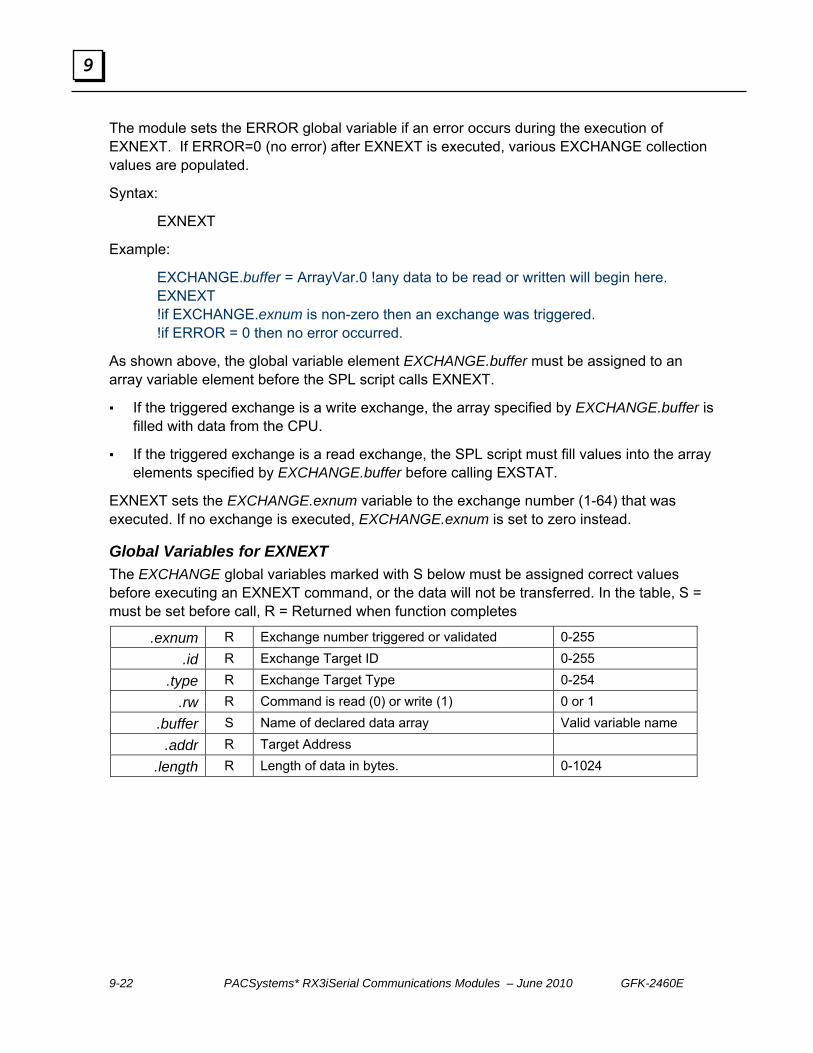
9-22 PACSystems* RX3iSerial Communications Modules – June 2010 GFK-2460E
9
The module sets the ERROR global variable if an error occurs during the execution of EXNEXT. If ERROR=0 (no error) after EXNEXT is executed, various EXCHANGE collection values are populated.
Syntax:
EXNEXT
Example:
EXCHANGE.buffer = ArrayVar.0 !any data to be read or written will begin here. EXNEXT !if EXCHANGE.exnum is non-zero then an exchange was triggered. !if ERROR = 0 then no error occurred.
As shown above, the global variable element EXCHANGE.buffer must be assigned to an array variable element before the SPL script calls EXNEXT.
If the triggered exchange is a write exchange, the array specified by EXCHANGE.buffer is filled with data from the CPU.
If the triggered exchange is a read exchange, the SPL script must fill values into the array elements specified by EXCHANGE.buffer before calling EXSTAT.
EXNEXT sets the EXCHANGE.exnum variable to the exchange number (1-64) that was executed. If no exchange is executed, EXCHANGE.exnum is set to zero instead.
Global Variables for EXNEXT The EXCHANGE global variables marked with S below must be assigned correct values before executing an EXNEXT command, or the data will not be transferred. In the table, S = must be set before call, R = Returned when function completes
.exnum R Exchange number triggered or validated 0-255
.id R Exchange Target ID 0-255
.type R Exchange Target Type 0-254
.rw R Command is read (0) or write (1) 0 or 1
.buffer S Name of declared data array Valid variable name
.addr R Target Address
.length R Length of data in bytes. 0-1024

GFK-2460E Chapter 9 Serial Protocol Language (SPL) 9-23
9
Statements to Exchange CPU Data: EXSTAT EXSTAT must be called upon completing an exchange returned by the EXNEXT command. EXSTAT provides the application program with status of the exchange processed by the SPL script. Error codes 0 to 19 are predefined. Error codes can be set up to suit the application, using values from 20 to 255 to indicate specific error conditions. For example, the following values are used in the SPL script shown at the end of this chapter:
!*** Exchange Errors: !*** 0=no error !*** 20=no ACK from slave !*** 21=invalid type !*** 22=failed to get ACK to header !*** 23=NAK'd 3 header retries !*** 24=not ACK or NAK following header !*** 25=timeout waiting for 1st char from slave data block !*** 26=timeout waiting for rest of data block from slave !*** 27=rcvd more chars than expected for data block !*** 28=rcvd data block failed 3 times !*** 29=EOT timeout from Slave !*** 30=not an EOT from Slave !*** 31=timeout waiting for ACK/NAK from slave !*** 32=xmit data block failed 3 times !*** 33=not ACK or NAK following data block
Syntax:
EXSTAT [value]
Example:
ErrorCode = 0 EXSTAT ErrorCode !Exchange complete without error
EXSTAT Errors
EXSTAT does not set the ERROR global variable with the value of the argument that follows it (that is, the script-defined error number like the examples shown above).

9-24 PACSystems* RX3iSerial Communications Modules – June 2010 GFK-2460E
9
Using EXNEXT and EXSTAT Operation of EXNEXT and EXSTAT when reading and writing data is described below. First, EXCHANGE.buffer is assigned to an array variable. Then EXNEXT is encountered.
EXCHANGE.buffer = arrayVar.0 EXNEXT
The module looks for the next Controlled Exchange that is ready. In this example, that is Data Exchange 32, a write exchange. The following values are now available to the SPL script:
EXCHANGE.exnum =32 EXCHANGE.id = Exchange #32’s target ID. EXCHANGE.type = Exchange #32’s target type. EXCHANGE.rw = 1 (write) EXCHANGE.addr = Exchange #32’s Target Address. EXCHANGE.length = Exchange #32’s Ref length in bytes. arrayVar.0 – arrayVar.[EXCHANGE.length-1] filled with the bytes from the CPU reference memory specified for exchange #32.
If ERROR is not zero after the EXNEXT command, there was an error. In that case, EXCHANGE.length is 0 and no data is written into arrayVar. If ERROR is zero, the SPL script processes the arrayVar data.
EXSTAT 0 (exchange completed successfully)
The response bit for exchange 32 in the port’s Input Status Data is set to indicate completion.
The next time EXNEXT is encountered in the SPL script, the exchanges are evaluated beginning at 33. Data Exchange 33 is a read exchange that is ready to execute. The following values are now available to the SPL script:
EXCHANGE.exnum =33 EXCHANGE.id = Exchange #33’s target ID. EXCHANGE.type = Exchange #33’s target type. EXCHANGE.rw = 0 (read) EXCHANGE.addr = Exchange #33’s Target Address. EXCHANGE.length = Exchange #33’s Ref length in bytes.
SPL fills arrayVar.0 – arrayVar.[EXCHANGE.length-1] with data to be sent to the CPU reference memory specified for exchange #33.
EXSTAT 0
The module sends the data in arrayVar.0 to the CPU reference memory and tells the application logic that the exchange completed successfully

GFK-2460E Chapter 9 Serial Protocol Language (SPL) 9-25
9
After the EXSTAT command, if ERROR is not zero an error has occurred and data is sent to the CPU for the exchange that was just triggered. Values above 20 are user-defined. Values 0 through 19 are reserved for general errors.
The module sets Exchange 33’s response bit in the port status data to indicate exchange complete.
If EXNEXT is called and no exchange has been triggered, EXCHANGE.exnum will be 0. The script should check the value of EXCHANGE.exnum after a call to EXNEXT to determine whether an exchange is ready to be processed. The value 0 means no exchange was found.
EXSTAT should not be called when EXCHANGE.exnum = 0. If the script calls EXSTAT when EXCHANGE.exnum =0, a fatal error occurs.
On the Command Line Interface, the following display would indicate the error:
[EXSTAT]
Reason: code [43] EXNEXT must be executed prior to EXSTAT
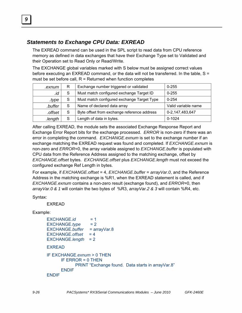
9-26 PACSystems* RX3iSerial Communications Modules – June 2010 GFK-2460E
9
Statements to Exchange CPU Data: EXREAD The EXREAD command can be used in the SPL script to read data from CPU reference memory as defined in data exchanges that have their Exchange Type set to Validated and their Operation set to Read Only or Read/Write. The EXCHANGE global variables marked with S below must be assigned correct values before executing an EXREAD command, or the data will not be transferred. In the table, S = must be set before call, R = Returned when function completes
.exnum R Exchange number triggered or validated 0-255
.id S Must match configured exchange Target ID 0-255
.type S Must match configured exchange Target Type 0-254
.buffer S Name of declared data array Valid variable name
.offset S Byte offset from exchange reference address 0-2,147,483,647
.length S Length of data in bytes. 0-1024
After calling EXREAD, the module sets the associated Exchange Response Report and Exchange Error Report bits for the exchange processed. ERROR is non-zero if there was an error in completing the command. EXCHANGE.exnum is set to the exchange number if an exchange matching the EXREAD request was found and completed. If EXCHANGE.exnum is non-zero and ERROR=0, the array variable assigned to EXCHANGE.buffer is populated with CPU data from the Reference Address assigned to the matching exchange, offset by EXCHANGE.offset bytes. EXCHANGE.offset plus EXCHANGE.length must not exceed the configured exchange Ref Length in bytes. For example, if EXCHANGE.offset = 4, EXCHANGE.buffer = arrayVar.0, and the Reference Address in the matching exchange is %R1, when the EXREAD statement is called, and if EXCHANGE.exnum contains a non-zero result (exchange found), and ERROR=0, then arrayVar.0 & 1 will contain the two bytes of %R3, arrayVar.2 & 3 will contain %R4, etc.
Syntax: EXREAD
Example: EXCHANGE.id = 1 EXCHANGE.type = 2 EXCHANGE.buffer = arrayVar.8 EXCHANGE.offset = 4 EXCHANGE.length = 2
EXREAD
IF EXCHANGE.exnum > 0 THEN IF ERROR = 0 THEN PRINT “Exchange found. Data starts in arrayVar.8” ENDIF ENDIF
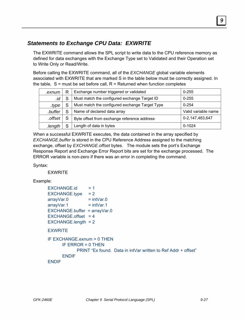
GFK-2460E Chapter 9 Serial Protocol Language (SPL) 9-27
9
Statements to Exchange CPU Data: EXWRITE The EXWRITE command allows the SPL script to write data to the CPU reference memory as defined for data exchanges with the Exchange Type set to Validated and their Operation set to Write Only or Read/Write.
Before calling the EXWRITE command, all of the EXCHANGE global variable elements associated with EXWRITE that are marked S in the table below must be correctly assigned. In the table, S = must be set before call, R = Returned when function completes
.exnum R Exchange number triggered or validated 0-255
.id S Must match the configured exchange Target ID 0-255
.type S Must match the configured exchange Target Type 0-254
.buffer S Name of declared data array Valid variable name
.offset S Byte offset from exchange reference address· 0-2,147,483,647
.length S Length of data in bytes 0-1024
When a successful EXWRITE executes, the data contained in the array specified by EXCHANGE.buffer is stored in the CPU Reference Address assigned to the matching exchange, offset by EXCHANGE.offset bytes. The module sets the port’s Exchange Response Report and Exchange Error Report bits are set for the exchange processed. The ERROR variable is non-zero if there was an error in completing the command.
Syntax: EXWRITE
Example: EXCHANGE.id = 1 EXCHANGE.type = 2 arrayVar.0 = intVar.0 arrayVar.1 = intVar.1 EXCHANGE.buffer = arrayVar.0 EXCHANGE.offset = 4 EXCHANGE.length = 2
EXWRITE
IF EXCHANGE.exnum > 0 THEN IF ERROR = 0 THEN PRINT “Ex found. Data in intVar written to Ref Addr + offset” ENDIF ENDIF

9-28 PACSystems* RX3iSerial Communications Modules – June 2010 GFK-2460E
9
Global Variable: EXCHANGE The EXCHANGE global variable is used with the SPL statements that exchange data with the RX3i PLC CPU: EXNEXT, EXREAD, and EXWRITE.
EXCHANGE has several sub-elements described below, which use dot (‘.’) notation, i.e. EXCHANGE.length.
Description Values .addr Controlled Exchange: Target Address 0-65535
.buffer Name of declared data array Valid variable name .exnum Exchange number triggered or validated 0-255
.id Generic target ID 0-255 .length Length of data in bytes 0-1024 .offset Byte offset from exchange reference address·
EXCHANGE.offset plus EXCHANGE.length must be less than or equal to the Configured exchange Ref Length when converted to bytes.
0-2,147,483,647
.rw Command is read(0) or write(1) 0, 1 .type Generic data type identifier 0-254
Depending on the statement being executed, these sub-elements either supply required information or receive information about the action, as listed below. Sub-elements that supply information must be set before the statement in the SPL script. Sub-elements that receive information must be located after the statement in the SPL script.
EXNEXT EXREAD EXWRITE .addr Returned after Not used Not used
.buffer Set before Set before Set before .exnum Returned after Returned after Returned after
.id Returned after Set before Set before .length Returned after Set before Set before .offset Not used Set before Set before
.rw Returned after Not used Not used .type Returned after Set before Set before
EXCHANGE.buffer sets up the buffer in the module for data that will be read or written. EXCHANGE.buffer must be assigned to an array variable element before the SPL script calls EXNEXT, EXREAD, or EXWRITE. For a write exchange, the array specified by EXCHANGE.buffer must be filled with data to be written to the CPU. For a read exchange, the array specified by EXCHANGE.buffer is filled with data from the CPU.
See the descriptions of EXNEXT, EXREAD, and EXWRITE in this chapter for details.

GFK-2460E Chapter 9 Serial Protocol Language (SPL) 9-29
9
SPL Statements and Global Variables for Serial Communications
This section describes the SPL statements and global variables that can be used in the SPL script to send and receive serial data:
GETB Returns up to N char(s) from serial port
PUTB Sends N char(s) to serial port
In addition to using these two statements for serial data transfer, the SPL script should use the SERIAL global variable to control and monitor serial communications on the port.
SPL Statements for Exchanging Serial Port Data: GETB The GETB statement returns up to [count] bytes of data from the serial port subsystem to [array ref] and returns the total number of bytes copied into [array ref].
Syntax:
variable = GETB [array ref] [count]
Example:
DIM msg ARRAY DIM count INTEGER
count = GETB msg.5 10
All available data is returned if there are fewer than [count] data bytes in serial buffer. If an error occurs, the module sets the ERROR variable in the SPL script. The value of the ERROR variable is mirrored in the port’s input status data.
If a line error is encountered, the corrupt data is discarded and the SERIAL.rxerror global variable is incremented. The error id is reported in the ERROR variable the next time GETB is called.
If the buffer overflows, all new data is discarded, the overrun count increments and the ERROR variable is set the next time GETB is called. All runtime errors, such as not enough space for data requested, generate an error at the time GETB is called, and will set ERROR and cause a fatal fault

9-30 PACSystems* RX3iSerial Communications Modules – June 2010 GFK-2460E
9
SPL Statements for Exchanging Serial Port Data: PUTB The PUTB statement transfers [count] bytes of data from [array reference] to the serial port transmit buffer and returns number of bytes that have been queued for transmit.
Syntax:
variable = PUTB [array reference] [count]
If the SPL script transfers data to the serial port transmit buffer too quickly, it can cause an overflow of the transmit buffer. The SPL script can prevent a buffer overflow by monitoring the state of the SERIAL.txstate variable. SERIAL.txstate should be 0 (idle).
If an error occurs, the ERROR global variable is set.
Example:
DIM count INTEGER DIM msg ARRAY
msg.0 = ‘S’ msg.1 = ‘P’ msg.2 = ‘L’
count = PUTB msg.0 3

GFK-2460E Chapter 9 Serial Protocol Language (SPL) 9-31
9
Global Variable for Serial Communications: SERIAL The SPL script uses the GETB and PUTB statements to write bytes or read bytes of data using serial communications.
Those statements are used in conjunction with the SERIAL global variable, which is central to the port’s serial communications. It provides the SPL script with both control over serial communications, and status information about them. The SERIAL global variable has several sub-elements, which may be accessed using dot (‘.’) notation, for example: SERIAL.inlen.
The SPL script uses the SERIAL global variable sub-elements to: set the value of the RTS line obtain the value of the CTS line clear the transmit and receive buffer clear the serial status variables check the state of serial communications check the number of overrun errors and receive errors
Variable Description R/W Range
.txstate State of serial system (Idle, Transmitting ) 0 = Idle 1 = Turn around time wait or CTS wait in Full Duplex 2 = RTS on and waiting the TX RTS Min Drop Delay Time 3 = TX_IN_PROGRESS 4 = RTS on, transmission completed and waiting the TX RTS Min Drop Delay Time
R 0-4
.overrun Number of overrun errors since variable last cleared R 0-65535
.rxerror Number of receive errors since variable last cleared R 0-65535
.inlen Number of bytes currently in receive buffer ( 0 – 2k ) R 0-2048
.rts Sets the value of the RTS line ( 0, 1 ) W 0,1
.cts Returns the value of the CTS line ( 0, 1 ) R 0,1
Clears or resets variables or buffers in serial system W 1-4
1 Clears Tx buffer
2 Clears Rx buffer
3 Clears status variables
.clear
4 Clears Tx buffer, Rx buffer and Status variables
All counts are held at maximum value until cleared, all state variables change as state changes.

9-32 PACSystems* RX3iSerial Communications Modules – June 2010 GFK-2460E
9
Optional Global Variables for Serial Communications SPL provides two global variables that can be used by the RX3i CPU to send communications information to the SPL port, and to read communications status information from the port. If either of these global variables is used, its meaning must be defined in the SPL script.
Global Variables: IOCTRL The global variable IOCTRL is a 5-byte array that represents the content of bytes 12 through 16 of the port’s Output Control Data in the PLC CPU. The CPU application program is responsible for supplying the content of the Output Control Data to the assigned reference addresses. The entire set of port Output Control Data is automatically written to the port during the CPU’s regular I/O scan. Output Control Data is described in detail in chapter 4.
The use of bytes 12 through 16 of the Output Control Data is optional, and not all protocols will require it. For example, the module’s built-in MODBUS protocol does not use these Output Control Data CPU memory references, while the Serial I/O protocol uses them for commands from the CPU, such as activate RTS and cancel pending operation (detailed in chapter 4).
The SPL script can read each element of the 5-byte IOCTRL array using dot notation. For example:
Var = IOCTRL.3
Global Variables: IOSTAT The global variable IOSTAT is a 5-byte array that represents the content of bytes 20 through 25 of the port’s Input Status Data in the PLC CPU. The entire set of port Input Status Data is automatically read by the CPU during its regular I/O scan, and placed into its assigned reference addresses. The CPU application program is responsible for monitoring the content of the port’s Input Status Data. Input Status Data is described in detail in chapter 4.
The use of bytes 20 through 25 of the Input Status Data is optional, and not all protocols will require it. For example, the module’s built-in MODBUS protocol does not use these Input Status Data CPU memory references, while the Serial I/O protocol uses the references for CTS status, number of input buffer characters available, and number of characters received (detailed in chapter 4).
The SPL script can write each element of IOSTAT using dot notation. For example:
IOSTAT.4 = 3

GFK-2460E Chapter 9 Serial Protocol Language (SPL) 9-33
9
Checksum Statements SPL includes two statements that can be used to calculate checksums in the SPL script:
BCC Calculate BCC of data array
CRC Calculate 16 bit CRC of data array
Checksum Statements: BCC The BCC statement calculates the Block Check Character (BCC) of data starting at [array reference] for [length] bytes . This 8-bit value is calculated by taking the eXclusive OR (XOR) of the data. If an error occurs, the module sets the ERROR variable.
Syntax:
variable = BCC [array reference] [length]
Example:
DIM msgbcc INTEGER DIM msg ARRAY
Msg.0 = 5 ……
!calculate BCC for bytes 0-9 and put in byte 10 msgbcc = BCC msg.0 10 msg.10 = msgbcc
Checksum Statements: CRC The CRC statement calculates a 16-bit Cyclic Redundancy Check of a series of data starting at [data reference] for [length] bytes. CRC16 is based on the polynomial x^16+x^15+x^2+1 and uses 0xFFFF as the seed value. If an error occurs, the module sets the ERROR variable.
Syntax:
variable = CRC [array reference] [length]
Example:
DIM msg ARRAY DIM crcvar INTEGER
! Compute the CRC for bytes 3-21 and put in bytes 22 and 23. crcvar = CRC msg.3 19 msg.22 = crcvar.0 msg.23 = crcvar.1

9-34 PACSystems* RX3iSerial Communications Modules – June 2010 GFK-2460E
9
Mathematical and Logical Operators The following logical operators can be used in an SPL script. The data types used in a logical operation must match (two integers or two array elements(bytes)).
Operator Description
< Less than > Greater than = Equals or assign ( meaning in context ) + Plus ( add 2 values ) - Minus * Multiply / Divide
<= Less than or equal >= Greater than or equal <> Not equal
AND AND OR OR
XOR Exclusive OR MOD Modulus – remainder of division
Precedence of Operators Mathematical and logical operations are performed with the following precedence:
1. Operators that are contained in parentheses ( )
2. Negation (-)
3. Multiplication (*), Division (/), MOD
4. Addition (+) and Subtraction (-)
5. Relational Expressions (=, <>, >, <, >=, <=)
6. Bitwise AND
7. Bitwise OR
8. Bitwise XOR

GFK-2460E Chapter 9 Serial Protocol Language (SPL) 9-35
9
Logical Operators: AND The AND operator performs a bitwise AND of two integers or array elements. The module sets the ERROR variable if an error occurs. The possible results of the AND operation are:
EXP1 EXP2 Result
0 0 0 0 1 0 1 0 0 1 1 1
Syntax:
exp1 AND exp2
Example:
DIM intvar INTEGER DIM intvar2 INTEGER intvar = intvar2 AND 55H
Logical Operators: OR The OR operator performs a bitwise OR of two integers or array elements. The module sets the ERROR variable if an error occurs. The possible results of the OR operation are:
EXP1 EXP2 Result
0 0 0 0 1 1 1 0 1 1 1 1
Syntax:
exp1 OR exp2
Example:
DIM intvar INTEGER DIM intvar2 INTEGER intvar = intvar2 OR 55H

9-36 PACSystems* RX3iSerial Communications Modules – June 2010 GFK-2460E
9
Logical Operators: XOR The XOR operator performs a bitwise XOR of two integers or array elements. The module sets the ERROR variable if an error occurs. The possible results of the OR operation are:
EXP1 EXP2 Result
0 0 0 0 1 1 1 0 1 1 1 0
Syntax:
exp1 XOR exp2
Example:
DIM intvar INTEGER DIM intvar2 INTEGER intvar = intvar2 XOR 55H
Logical Operators: MOD The MOD operator returns the remainder of [variable1] divided by [variable2]. The module sets the ERROR variable if the value of variable2 is zero.
Syntax:
variable = [variable1] MOD [variable2]
Example:
DIM intvar INTEGER DIM intvar2 INTEGER intvar = intvar2 MOD 100

GFK-2460E Chapter 9 Serial Protocol Language (SPL) 9-37
9
SPL Statements for ASCII Conversions Two conversion statements can be used in the SPL script to convert an ASCII character to a numeric value or to convert a numeric value to ASCII.
ASCTOVAL Converts characters to a value
VALTOASC Converts value to characters
ASCII Conversion Statements: ASCTOVAL The ASCTOVAL statement converts characters in an array variable to a numeric value. It returns the converted value.
[array reference] = starting position of the array at which to begin the conversion.
[length] = how many characters to include in the conversion.
[type] = how to interpret the characters. ‘D’ = decimal. ’H’= hexadecimal.
The module sets the ERROR variable if an error occurs. Possible errors include overflow and invalid characters for the conversion. Invalid characters include: ‘0x’, ‘H’, ‘+’, ‘-‘, ‘.’. Hexadecimal characters may be either uppercase or lowercase.
Syntax:
variable = ASCTOVAL [array reference] [length] [type]
Example1:
ArrayVar.2 = ‘1’ ArrayVar.3 = ‘A’ ArrayVar.4 = ‘6’
! IntVar will equal 422 after the next line execution, Hex 1A6 = 422 decimal.
IntVar = ASCTOVAL ArrayVar.2 3 H !convert 3 hex chars to integer
Example 2:
ArrayVar.2 = ‘-’ ArrayVar.3 = ‘6’ ArrayVar.4 = ‘4’
! IntVar will equal -64 after the next line execution.
IntVar = ASCTOVAL ArrayVar.2 3 D !convert 3 decimal chars to integer

9-38 PACSystems* RX3iSerial Communications Modules – June 2010 GFK-2460E
9
ASCII Conversion Statements: VALTOASC The VALTOASC statement converts a value to characters stored within an array variable. Returns the number of characters that were converted.
[variable reference] = integer value to convert
[array reference] = starting position to put converted ASCII values
[type] = conversion format. ‘D’ = decimal. ’H’ = hexadecimal.
Syntax:
length = VALTOASC [variable reference] [array reference] [type]
Example1:
IntVar = 422 ! ArrayVar.2, 3, and 4 will equal ‘1’, ‘A’, ‘6’ and ! IntLength will equal 3 after the next line execution. ! Hex 1A6 = 422 decimal. IntLength = VALTOASC IntVal ArrayVar.2 H !convert integer to 3 hex chars
Example 2:
IntVar = -422 ! ArrayVar.2, 3, 4 and 5 will equal ‘-’, ‘4’, ‘2’ , ‘2’ and ! IntLength will equal 4 after the next line execution. IntLength = VALTOASC IntVal ArrayVar.2 D !convert integer to 4 dec chars
Example 3:
IntVar = 0FFFFFFFH !Integers are stored in 2’s complement ! ArrayVar.2 & 3will equal ‘-’, ‘1’and ! IntLength will equal 2 after the next line execution. IntLength = VALTOASC IntVal ArrayVar.2 D !convert integer to 2 dec chars

GFK-2460E Chapter 9 Serial Protocol Language (SPL) 9-39
9
SPL Statements to Read Time SPL provides two statements that can be used to read the value of a timer, or the elapsed time:
TIMER Returns mS timer value. Timer set to 0 on RUN. A separate timer is maintained for each SPL port.
ELAPSED Returns elapsed mS ( pass timestamp arg for calc )
Time Statements: TIMER The TIMER statement can be used in the SPL logic to read the current value of a free-running timer in milliseconds. The timer restarts at 0 at the beginning of Run mode. Range is 0 to 3,599,999 (1 hour ) after which it rolls back to 0.
Syntax:
IntegerVar = TIMER
Example:
StartTime = TIMER
Time Statements: ELAPSED The ELAPSED statement can be used in the SPL logic to read the elapsed time. ELAPSED returns the elapsed time in milliseconds since the timestamp in [integer variable]. Range is 0 to 3,600,000 (1 hour). This statement automatically handles rollover.
Syntax:
IntegerVar1 = ELAPSED [integer variable]
Example:
elapsed = ELAPSED EarlierTime

9-40 PACSystems* RX3iSerial Communications Modules – June 2010 GFK-2460E
9
Downloading the SPL Script The SPL script must be attached to the Target in Logic Developer, and downloaded to the CPU, as described in chapter 3. When the module is started up, it goes through its normal startup process then downloads from the CPU the module configuration, plus the SPL scripts for any ports that have been configured for SPL. While the module is receiving an SPL script, the Port Status word for that port remains in the configuring state, the SPL Port Status byte indicates “No program loaded”, and the port is not operational.
After the SPL script has been downloaded it begins to run if configured to do so (see chapter 3 for details). The SPL port sets the Port Status word in its Input Status Data (see chapter 4) to Port Ready. It also sets the SPL Port Status byte in its Input Status Data to the appropriate status for the current state of the SPL script, and the port begins to operate.
Debugging the SPL Script The SPL Script can be debugged using the SPL Command Line Interface, as described on the following pages. Using the Command Line Interface feature requires a computer running a terminal emulator, connected to a second port on the Serial Communications Module.
The Command Line Interface can issue commands to control the execution of the SPL script, but the Command Line Interface cannot be used to edit the SPL script. Any changes to the SPL script must be made using a text editor such as Notepad, and the file must again be saved with the extension: .spl, added to the target in Proficy Machine Edition, then downloaded as described above.
This can be done by connecting a computer to both the RX3i CPU and to the designated Command Line Interface port on the Serial Communications Module at the same time. If the computer is using a serial cable to connect to the CPU through the programmer, it must have two serial ports (one to connect to the CPU and one to connect to the Serial Communications Module.) If the computer is using Ethernet to connect to the CPU, it will only need one serial port to connect to the Serial Communications Module. The communications parameters of the Command Line Interface port are:
Port Type: RS232
Baud Rate: 9600
Data Bits: 8
Parity: None
Stop Bits: 1
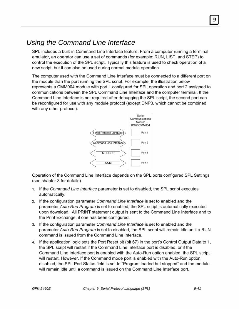
GFK-2460E Chapter 9 Serial Protocol Language (SPL) 9-41
9
Using the Command Line Interface SPL includes a built-in Command Line Interface feature. From a computer running a terminal emulator, an operator can use a set of commands (for example: RUN, LIST, and STEP) to control the execution of the SPL script. Typically this feature is used to check operation of a new script, but it can also be used during normal module operation.
The computer used with the Command Line Interface must be connected to a different port on the module than the port running the SPL script. For example, the illustration below represents a CMM004 module with port 1 configured for SPL operation and port 2 assigned to communications between the SPL Command Line Interface and the computer terminal. If the Command Line Interface is not required after debugging the SPL script, the second port can be reconfigured for use with any module protocol (except DNP3, which cannot be combined with any other protocol).
Serial Communications
Module IC695CMM004
Serial Protocol Language
Command Line Interface
MODBUS
CCM
Port 1
Port 2
Port 3
Port 4
Operation of the Command Line Interface depends on the SPL ports configured SPL Settings (see chapter 3 for details).
1. If the Command Line Interface parameter is set to disabled, the SPL script executes automatically.
2. If the configuration parameter Command Line Interface is set to enabled and the parameter Auto-Run Program is set to enabled, the SPL script is automatically executed upon download. All PRINT statement output is sent to the Command Line Interface and to the Print Exchange, if one has been configured.
3. If the configuration parameter Command Line Interface is set to enabled and the parameter Auto-Run Program is set to disabled, the SPL script will remain idle until a RUN command is issued from the Command Line Interface.
4. If the application logic sets the Port Reset bit (bit 67) in the port’s Control Output Data to 1, the SPL script will restart if the Command Line Interface port is disabled, or if the Command Line Interface port is enabled with the Auto-Run option enabled, the SPL script will restart. However, If the Command mode port is enabled with the Auto-Run option disabled, the SPL Port Status field is set to “Program loaded but stopped” and the module will remain idle until a command is issued on the Command Line Interface port.

9-42 PACSystems* RX3iSerial Communications Modules – June 2010 GFK-2460E
9
Control SPL Script Execution from the Command Line Interface Port The following commands can be entered manually on a terminal connected to a module port that is configured as the Command Line Interface. Except for the PRINT command, these commands may not be included in an SPL script.
RUN Causes SPL script to begin running from start of program
STEP Execute one line of SPL and stop
CONT Causes SPL script to begin running from current line
LIST List program
Commands: RUN The RUN command can only be issued via the Command Line Interface. If RUN is issued, the SPL script re-initializes user variables, global variables and stacks, and starts running from the beginning. The script executes until stopped by entering <CTRL-C> from the terminal, or until it reaches a STOP statement in the logic.
To instead restart the SPL script at the current point in the logic without re-initializing variables and stacks use the CONT command.
Syntax:
RUN
Example (in these examples, 2> represents the Command Line Interface prompt for port 2):
2> RUN

GFK-2460E Chapter 9 Serial Protocol Language (SPL) 9-43
9
Commands: STEP The STEP command can only be issued via the Command Line Interface.
When the module receives the STEP command, it executes one line of the SPL script, then returns control to the Command Line Interface port. The line that was executed is printed. You can enter either STEP or S; they are equivalent.
Syntax:
STEP S
Example:
<CTRL-C> 2> STEP somevar = 6 2> S PRINT somevar 6 2>
Commands: CONT The CONT command can only be issued via the Command Line Interface. When the module receives the CONT command, an SPL script that has been stopped by a <CTRL-C> from the Command Line Interface or by a STOP statement in the script will restart at the current location in the script. All user variables, global variables and stacks are preserved.
To instead restart the SPL script from the beginning and reinitialize all variables and stacks, use the RUN command.
Syntax:
CONT
Example:
2> RUN 2> <CTRL-C> ….. 2> CONT

9-44 PACSystems* RX3iSerial Communications Modules – June 2010 GFK-2460E
9
Commands: LIST The LIST command can only be executed via the Command Line Interface. This command displays the SPL script, plus the following information about the program:
1. the number of lines in the program.
2. the size in bytes of the program.
3. the amount of memory remaining for program storage.
Syntax:
LIST
Example:
1> LIST
00001 DIM i INTEGER
00002 i = 35
00003 PRINT i
Total program Lines: 3
Total program length: 33
Available storage: 32735
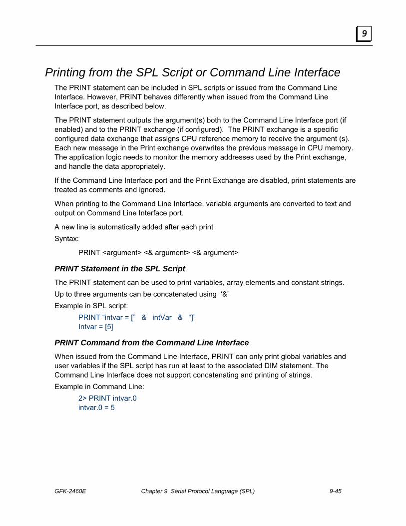
GFK-2460E Chapter 9 Serial Protocol Language (SPL) 9-45
9
Printing from the SPL Script or Command Line Interface The PRINT statement can be included in SPL scripts or issued from the Command Line Interface. However, PRINT behaves differently when issued from the Command Line Interface port, as described below.
The PRINT statement outputs the argument(s) both to the Command Line Interface port (if enabled) and to the PRINT exchange (if configured). The PRINT exchange is a specific configured data exchange that assigns CPU reference memory to receive the argument (s). Each new message in the Print exchange overwrites the previous message in CPU memory. The application logic needs to monitor the memory addresses used by the Print exchange, and handle the data appropriately.
If the Command Line Interface port and the Print Exchange are disabled, print statements are treated as comments and ignored.
When printing to the Command Line Interface, variable arguments are converted to text and output on Command Line Interface port.
A new line is automatically added after each print Syntax:
PRINT <argument> <& argument> <& argument>
PRINT Statement in the SPL Script The PRINT statement can be used to print variables, array elements and constant strings. Up to three arguments can be concatenated using ‘&’ Example in SPL script:
PRINT “intvar = [” & intVar & “]” Intvar = [5]
PRINT Command from the Command Line Interface When issued from the Command Line Interface, PRINT can only print global variables and user variables if the SPL script has run at least to the associated DIM statement. The Command Line Interface does not support concatenating and printing of strings. Example in Command Line:
2> PRINT intvar.0 intvar.0 = 5

9-46 PACSystems* RX3iSerial Communications Modules – June 2010 GFK-2460E
9
Sample SPL Script The SPL script that makes up the rest of this chapter is intended only as an example. It has not been tested, and should not be used as-is. !**************************************** !*** Sample protocol written !*** using Serial Protocol Language (SPL) !*** Assume 9600 baud (about 1ms per char) !*** with 10mS turn around !*** N sequence Only, no Q sequence !*** Handles all types but only passes full bytes !*** and allows R/W to any type !*** Exchange Errors: !*** 0=no error !*** 20=no ACK from slave !*** 21=invalid type !*** 22=failed to get ACK to header !*** 23=NAK'd 3 header retries !*** 24=not ACK or NAK following header !*** 25=timeout waiting for 1st char from slave data block !*** 26=timeout waiting for rest of data block from slave !*** 27=rcvd more chars than expected for data block !*** 28=rcvd data block failed 3 times !***29=EOT timeout from Slave !*** 30=not an EOT from Slave !*** 31=timeout waiting for ACK/NAK from slave !*** 32=xmit data block failed 3 times !*** 33=not ACK or NAK following data block !**************************************** DIM Msg ARRAY DIM CpuMem ARRAY DIM tempArray ARRAY DIM DataPtr INTEGER DIM CurrentState INTEGER DIM ExFound INTEGER DIM i INTEGER DIM Retry INTEGER DIM temp INTEGER DIM temp1 INTEGER DIM flag INTEGER DIM BeginLrc INTEGER DIM EndLrc INTEGER DIM lrc INTEGER DIM BlocksLeft INTEGER DIM LastBlockLen INTEGER DIM ExpectedLen INTEGER

GFK-2460E Chapter 9 Serial Protocol Language (SPL) 9-47
9
DIM ErrorCode INTEGER DIM Time INTEGER DIM ENQ INTEGER DIM ACK INTEGER DIM STX INTEGER DIM ETB INTEGER DIM EOT INTEGER DIM ETX INTEGER DIM NAK INTEGER DIM SOH INTEGER DIM BResult INTEGER ! temporary variable to store results from GETB and PUTB DIM LastCurState INTEGER ACK = 6 ENQ = 5 EOT = 4 ETB = 23 ETX = 3 NAK = 21 SOH = 1 STX = 2 CurrentState = 0 !Init :top !only print current state if changed IF CurrentState <> LastCurState THEN LastCurState = CurrentState PRINT "CurrentState=" & CurrentState ENDIF GOTO JumpTable !*** 0 INIT :State0 CurrentState = 10 !send ENQ Retry = 0 GOTO top !*** 10 CHECK FOR EXCHANGE :State10 EXCHANGE.buffer = CpuMem.0 !where to put the CPU data EXNEXT ExFound = EXCHANGE.exnum IF ExFound > 0 THEN !Exchange triggered
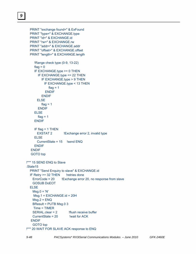
9-48 PACSystems* RX3iSerial Communications Modules – June 2010 GFK-2460E
9
PRINT "exchange found=" & ExFound PRINT "type=" & EXCHANGE.type PRINT "id=" & EXCHANGE.id PRINT "rw=" & EXCHANGE.rw PRINT "addr=" & EXCHANGE.addr PRINT "offset=" & EXCHANGE.offset PRINT "length=" & EXCHANGE.length !Range check type (0-9, 13-22) flag = 0 IF EXCHANGE.type >= 0 THEN IF EXCHANGE.type <= 22 THEN IF EXCHANGE.type > 9 THEN IF EXCHANGE.type < 13 THEN flag = 1 ENDIF ENDIF ELSE flag = 1 ENDIF ELSE flag = 1 ENDIF IF flag = 1 THEN EXSTAT 2 !Exchange error 2, invalid type ELSE CurrentState = 15 !send ENQ ENDIF ENDIF GOTO top !*** 15 SEND ENQ to Slave :State15 PRINT "Send Enquiry to slave" & EXCHANGE.id IF Retry >= 32 THEN !retries done ErrorCode = 20 !Exchange error 20, no response from slave GOSUB DoEOT ELSE Msg.0 = 'N' Msg.1 = EXCHANGE.id + 20H Msg.2 = ENQ BResult = PUTB Msg.0 3 Time = TIMER SERIAL.clear = 2 !flush receive buffer CurrentState = 20 !wait for ACK ENDIF GOTO top !*** 20 WAIT FOR SLAVE ACK response to ENQ

GFK-2460E Chapter 9 Serial Protocol Language (SPL) 9-49
9
:State20 temp = ELAPSED Time IF temp > 810 THEN !ACK following ENQ !*** timeout Retry = Retry + 1 CurrentState = 15 !Send another ENQ ELSE !*** hasn't timed out, look for ACK IF SERIAL.inlen >= 3 THEN BResult = GETB Msg.0 3 flag = 0 IF Msg.0 <> 'N' THEN flag = 1 ENDIF temp1 = EXCHANGE.id + 20H IF Msg.1 <> temp1 THEN flag = 1 ENDIF IF Msg.2 <> ACK THEN flag = 1 ENDIF IF flag = 1 THEN Retry = Retry + 1 Time = TIMER CurrentState = 25 !delay ELSE CurrentState = 30 !received ACK Retry = 0 !for header retries ENDIF ENDIF ENDIF GOTO top !*** 25 DELAY BEFORE ANOTHER ENQ :State25 temp = ELAPSED Time IF temp >= 810 THEN CurrentState = 15 ENDIF GOTO top !*** 30 BUILD & SEND MASTER HEADER :State30 Msg.1 = SOH !*** Target ID

9-50 PACSystems* RX3iSerial Communications Modules – June 2010 GFK-2460E
9
temp = EXCHANGE.id + 100H !100-1FE temp = VALTOASC temp tempArray.0 H !convert to hex characters Msg.2 = tempArray.1 !Target ID Msg.3 = tempArray.2 !*** Date Flow IF EXCHANGE.rw = 0 THEN !read Msg.4 = '0' ELSE !write IF EXCHANGE.type > 15 THEN Msg.4 = '9' ELSE Msg.4 = '8' ENDIF ENDIF !*** Target Mem type temp = EXCHANGE.type AND 0FH !get LS nibble temp = VALTOASC temp tempArray.0 H !convert to hex characters Msg.5 = tempArray.0 !lsb of type in ASCII coded hex !*** Target Mem address temp = EXCHANGE.addr + 10000H temp = VALTOASC temp tempArray.0 H !convert to hex characters Msg.6 = tempArray.1 !msb of addr Msg.7 = tempArray.2 Msg.8 = tempArray.3 Msg.9 = tempArray.4 !lsb of addr !*** complete blocks temp = EXCHANGE.length + 10000H !length in bytes temp = VALTOASC temp tempArray.0 H !convert to hex characters Msg.10 = tempArray.1 !msb of length Msg.11 = tempArray.2 !*** bytes in last block Msg.12 = tempArray.3 Msg.13 = tempArray.4 !lsb of length !*** Source ID (90) Msg.14 = '9' Msg.15 = '0' Msg.16 = ETB BeginLrc = 2 EndLrc = 15 GOSUB DoLRC Msg.17 = lrc SERIAL.clear = 2 !flush receive buffer

GFK-2460E Chapter 9 Serial Protocol Language (SPL) 9-51
9
BResult = PUTB Msg.1 17 !send header !*** calc number of data blocks temp = EXCHANGE.length BlocksLeft = temp.1 !number of full blocks DataPtr = 0 !point to 1st data element IF temp.0 > 0 THEN LastBlockLen = temp.0 BlocksLeft = BlocksLeft + 1 !partial block ELSE LastBlockLen = 0 !multiple of 256 bytes ENDIF Retry = Retry + 1 Time = TIMER CurrentState = 40 !wait for slave ACK to header GOTO top !*** 40 WAIT FOR SLAVE ACK TO HEADER :State40 temp = ELAPSED Time IF temp >= 2010 THEN ErrorCode = 22 !No ack to header GOSUB DoEOT ELSE IF SERIAL.inlen > 0 THEN BResult = GETB Msg.0 1 IF Msg.0 = NAK THEN IF Retry >= 3 THEN ErrorCode = 23 !>3 header retries GOSUB DoEOT ELSE CurrentState = 30 !retry header ENDIF ELSE IF Msg.0 = ACK THEN IF EXCHANGE.rw = 0 THEN !read CurrentState = 100 !read data from slave Time = TIMER Retry = 0 ELSE CurrentState = 200 !write data to slave Retry = 0 ENDIF ELSE !not ACK or NAK ErrorCode = 24 !not ACK or NAK following header GOSUB DoEOT ENDIF

9-52 PACSystems* RX3iSerial Communications Modules – June 2010 GFK-2460E
9
ENDIF ENDIF ENDIF GOTO top !**************************** !*** READ DATA FROM SLAVE !**************************** !*** 100 WAIT FOR 1ST CHAR OF DATA BLOCK :State100 temp = ELAPSED Time IF temp >= 20010 THEN ErrorCode = 25 !timeout on 1st char GOSUB DoEOT ELSE IF SERIAL.inlen > 0 THEN CurrentState = 110 !wait for rest of block ENDIF ENDIF GOTO top !*** 110 WAIT FOR ALL OF DATA BLOCK :State110 temp = ELAPSED Time IF temp >= 8350 THEN ErrorCode = 26 !timeout on data block GOSUB DoEOT ELSE !chars expecting to receive IF BlocksLeft > 1 THEN ExpectedLen = 259 !STX, 256, ETB, LRC ELSE IF LastBlockLen = 0 THEN ExpectedLen = 259 !STX, 256, ETB, LRC ELSE ExpectedLen = LastBlockLen + 3 !STX, data, ETX, LRC ENDIF ENDIF IF SERIAL.inlen > ExpectedLen THEN PRINT "ERROR 8:" & SERIAL.inlen & ExpectedLen ErrorCode = 27 !too many chars GOSUB DoEOT STOP ENDIF !received data block IF SERIAL.inlen = ExpectedLen THEN BResult = GETB Msg.0 ExpectedLen
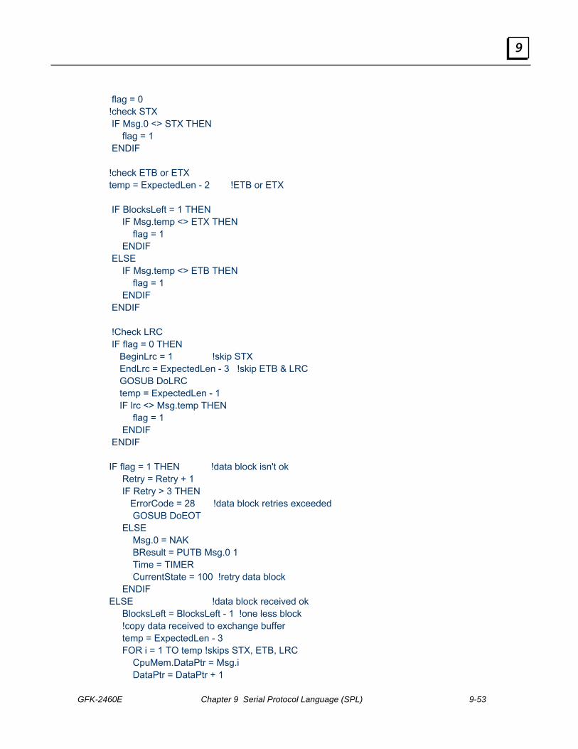
GFK-2460E Chapter 9 Serial Protocol Language (SPL) 9-53
9
flag = 0 !check STX IF Msg.0 <> STX THEN flag = 1 ENDIF !check ETB or ETX temp = ExpectedLen - 2 !ETB or ETX IF BlocksLeft = 1 THEN IF Msg.temp <> ETX THEN flag = 1 ENDIF ELSE IF Msg.temp <> ETB THEN flag = 1 ENDIF ENDIF !Check LRC IF flag = 0 THEN BeginLrc = 1 !skip STX EndLrc = ExpectedLen - 3 !skip ETB & LRC GOSUB DoLRC temp = ExpectedLen - 1 IF lrc <> Msg.temp THEN flag = 1 ENDIF ENDIF IF flag = 1 THEN !data block isn't ok Retry = Retry + 1 IF Retry > 3 THEN ErrorCode = 28 !data block retries exceeded GOSUB DoEOT ELSE Msg.0 = NAK BResult = PUTB Msg.0 1 Time = TIMER CurrentState = 100 !retry data block ENDIF ELSE !data block received ok BlocksLeft = BlocksLeft - 1 !one less block !copy data received to exchange buffer temp = ExpectedLen - 3 FOR i = 1 TO temp !skips STX, ETB, LRC CpuMem.DataPtr = Msg.i DataPtr = DataPtr + 1

9-54 PACSystems* RX3iSerial Communications Modules – June 2010 GFK-2460E
9
NEXT Msg.0 = ACK BResult = PUTB Msg.0 1 !check if last data block Time = TIMER IF BlocksLeft > 0 THEN CurrentState = 100 !retry data block ELSE CurrentState = 120 !wait for EOT ENDIF ENDIF ENDIF ENDIF GOTO top !*** 120 WAIT FOR SLAVE EOT :State120 temp = ELAPSED Time IF temp > 810 THEN ErrorCode = 29 !timeout waiting for EOT GOSUB DoEOT ELSE temp = SERIAL.inlen IF temp >= 1 THEN BResult = GETB Msg.0 1 IF Msg.0 = EOT THEN !*** SUCCESSFUL TRANSACTION !Data in CpuMem is passed back to CPU !When EXSTAT is called with no error PRINT "<<< Successful read from slave" ErrorCode = 0 !successful transaction GOSUB DoEOT !end session ELSE ErrorCode = 30 !not EOT GOSUB DoEOT !end session ENDIF ENDIF ENDIF GOTO top !**************************** !*** WRITE DATA TO SLAVE *** !**************************** !*** 200 WRITE DATA BLOCK :State200 !chars expecting to send IF BlocksLeft > 1 THEN ExpectedLen = 259 !STX, 256, ETB, LRC

GFK-2460E Chapter 9 Serial Protocol Language (SPL) 9-55
9
ELSE IF LastBlockLen = 0 THEN ExpectedLen = 259 !STX, 256, ETB, LRC ELSE ExpectedLen = LastBlockLen + 3 !STX, data, ETX, LRC ENDIF ENDIF Msg.0 = STX !copy exchange buffer to serial buffer temp = ExpectedLen - 3 FOR i = 1 TO temp !skips STX, ETB, LRC Msg.i = CpuMem.DataPtr DataPtr = DataPtr + 1 NEXT IF BlocksLeft = 1 THEN Msg.i = ETX ELSE Msg.i = ETB ENDIF BeginLrc = 1 !skip STX EndLrc = ExpectedLen - 3 !skip ETB & LRC GOSUB DoLRC i = i + 1 Msg.i = lrc SERIAL.clear = 2 !flush receive buffer BResult = PUTB Msg.0 ExpectedLen !send block Time = TIMER CurrentState = 210 GOTO top !*** 210 WAIT FOR SLAVE ACK :State210 temp = ELAPSED Time IF temp > 20010 THEN ErrorCode = 31 !timeout waiting for ACK GOSUB DoEOT ELSE IF SERIAL.inlen >= 1 THEN BResult = GETB Msg.0 1 flag = 0 IF Msg.0 = ACK THEN !slave liked data BlocksLeft = BlocksLeft - 1 IF BlocksLeft <= 0 THEN !no more blocks Msg.0 = EOT BResult = PUTB Msg.0 1 Time = TIMER GOSUB DoEOT !end session
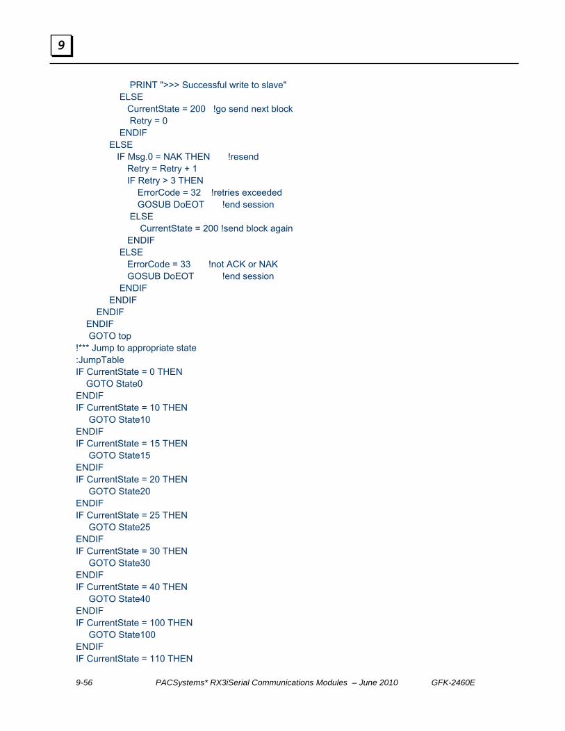
9-56 PACSystems* RX3iSerial Communications Modules – June 2010 GFK-2460E
9
PRINT ">>> Successful write to slave" ELSE CurrentState = 200 !go send next block Retry = 0 ENDIF ELSE IF Msg.0 = NAK THEN !resend Retry = Retry + 1 IF Retry > 3 THEN ErrorCode = 32 !retries exceeded GOSUB DoEOT !end session ELSE CurrentState = 200 !send block again ENDIF ELSE ErrorCode = 33 !not ACK or NAK GOSUB DoEOT !end session ENDIF ENDIF ENDIF ENDIF GOTO top !*** Jump to appropriate state :JumpTable IF CurrentState = 0 THEN GOTO State0 ENDIF IF CurrentState = 10 THEN GOTO State10 ENDIF IF CurrentState = 15 THEN GOTO State15 ENDIF IF CurrentState = 20 THEN GOTO State20 ENDIF IF CurrentState = 25 THEN GOTO State25 ENDIF IF CurrentState = 30 THEN GOTO State30 ENDIF IF CurrentState = 40 THEN GOTO State40 ENDIF IF CurrentState = 100 THEN GOTO State100 ENDIF IF CurrentState = 110 THEN

GFK-2460E Chapter 9 Serial Protocol Language (SPL) 9-57
9
GOTO State110 ENDIF IF CurrentState = 120 THEN GOTO State120 ENDIF IF CurrentState = 200 THEN GOTO State200 ENDIF IF CurrentState = 210 THEN GOTO State210 ENDIF PRINT "Illegal State =" & CurrentState CurrentState = 0 GOTO top !*** LRC subroutine *** ! BeginLrc first byte of Msg array ! EndLrc last byte of Msg Array ! lrc resultant LRC calculated. ! NOTE Could have used the BCC function. Wanted to ! do manually for showing XOR :DoLRC !lrc = 0 !FOR temp = BeginLrc TO EndLrc ! lrc = lrc.0 XOR Msg.temp !NEXT temp = 1 + EndLrc - BeginLrc lrc = BCC Msg.BeginLrc temp RETURN !*** Send EOT subroutine *** ! ErrorCode Error to send to exchange status :DoEOT Msg.0 = EOT BResult = PUTB Msg.0 1 EXSTAT ErrorCode !set exchange status CurrentState = 0 !back to init RETURN


Index
GFK-2460E Index-1
A Acknowledge Current Error, 4-13 Acknowledging Errors, 4-16 Application Response Timeout, DNP3, 3-
25, 3-36 Assignn Class, 3-30
B Baud Rates, 1-2 Bit Control, 3-11, 3-48
C Cancel Pending Operation, 4-14 Catalog Numbers, 1-2 CCM Commands, 7-3 CCM Memory Types, 7-4 CCM Protocol, 7-2 CCM Slave Communications, 1-10 CCM Slave Operations, 7-5 Change Event Data, 8-18
buffer, 8-55 format, 8-22 reading, 8-55
Change Event Reporting discontinuing, 8-21
Change Events for a DNP3 Slave Port, 8-53
Check Slave IIN, 3-26 Checksum, 3-4
Serial port, 3-4 SPL statements, 9-33
Class 1, 2, 3 Data, 8-19 Clear All Errors, 4-13 Clearing All Errors on a Port, 4-16 Clock Valid Period, 3-37 Clocks
time-of-day clock, 1-3 Cold Restart Command, 8-35 Cold Restart DNP3 function, 3-30 Command Line Interface, 9-41 COMMREQs, 1-6 Communications Standards, 1-4 Configuration ID, 3-4, 3-9, 3-14, 3-19 CPU Stopped, 4-2 CTS, 3-14, 3-19, 3-25, 3-36, 3-45 Current specifications, 1-3
D Data Bits, 1-3, 3-8, 3-13, 3-18, 3-24, 3-35,
3-45 Data Exchanges, 8-12 Data Rate, 3-8, 3-13, 3-18, 3-24, 3-35, 3-
45 Data Rates, 1-2 Debugging the SPL Script, 9-40 Delimiters, 3-6 Device Restart IIN Bit, 8-36 Diagnostics Data for CCM Slave Ports, 7-8 Diagnostics, Return Query Data, 5-19 Dial or Hang Up a Modem, 6-7 Distributed Network Protocol, 8-2 Distributed Network Protocol (DNP)
introduction, 1-11 DNP V3.0 Master Device Profile, 8-4 DNP V3.0 Master Implementation Table,
8-6 DNP V3.0 Slave Device Profile, 8-39 DNP V3.0 Slave Implementation Table, 8-
41 DNP3 event object types, 8-2 DNP3 Function Codes, 8-3 DNP3 Master Configuration, 3-24 DNP3 Master Data Exchanges, 3-27 DNP3 Master function configuration, 3-30 DNP3 Master Operation, 8-3 DNP3 object types, 8-2 DNP3 Slave Configuration, 3-35 DNP3 Slave Data Exchanges, 3-39, 3-47 DNP3 Slave Operation, 8-38 DNP3 Slave Point Lists, 8-46 DO I/O and Suspend I/O, 4-17 Documentation, 1-1 Downloading the SPL Script, 9-40 Drop Delay, 3-3, 3-9, 3-14, 3-19, 3-25, 3-
36, 3-45
E Error Selector, 4-14 Error Status Handling, 4-16
F Faults Reported, 1-2 Features, 1-2 Floating Point Support DNP3 Slave, 3-38 Flow Control, 3-3, 3-9, 3-14, 3-19, 3-25, 3-
36, 3-45 Flushing the Input Buffer, 4-15, 6-4

Index
Index-2 PACSystems* RX3iSerial Communications Modules User’s Manual–June 2010 GFK-2460E
Force Single Coil, 5-16 Four-Wire MODBUS, 2-10
G Grounding and Ground Loops, 2-9
H Hardware Flow Control, 6-3 Hazardous Locations, 2-2
I IIN Data, 8-17 Infolink, 1-1 Initializing (Resetting) the Port, 6-3 Input Buffer, 6-4 Input Buffer, 3-5 Input Data, 6-5 Input Data, 4-7 Isolation, 1-3
L LEDs, 2-3 Link Layer Confirmation, 3-25, 3-36 Link Max Retry Count, 3-25, 3-37 Loopback Maintenance, 5-19
M Machine Edition, 1-2 Mask Write 4x Memory, 5-23 Master Address, DNP3, 3-25 Modbus
reference tables, 5-5 MODBUS Cable, 2-8 MODBUS Communications Overview, 5-2 MODBUS Functions, 1-8, 5-6 MODBUS Master Configuration, 3-8 MODBUS Master Diagnostics, 5-10 MODBUS Master Operation, 5-8 MODBUS Message Formats, 5-4 MODBUS Multidrop Connections, 2-8 MODBUS Multidrop RS-485, 1-5 MODBUS Slave Configuration, 3-13, 3-18 MODBUS Slave Operation, 5-11 Modem, 6-7
Hayes-compatible, 6-7 Module LEDs, 2-3
N Normal Read Request from the CCM
Master, 7-6 Number of Modules, 1-2
O Object Class DNP3 Master, 3-31 Object Class DNP3 Slave, 3-42 Operate, DNP3 function, 3-30 Order Numbers, 1-2 Output Data, 4-11 Outputs Disabled, 4-2 Outputs Disabled Control, 3-25, 3-36 Outstation Address, 3-29, 3-36
P Parity, 1-3, 3-3, 3-8, 3-24, 3-35, 3-45 Periodic Sync Timeout Required, 3-37 PLC Access, 3-16 Point to Point Serial Connections, 2-7 Port configuration for SPL, 9-2 Port LEDs, 2-3 Port Pin Assignments, 2-4 Port Reset, 4-13 Port Status, 6-4 Port Status Input Data, 4-3 Port Type, 3-3, 3-8 Port Type, 3-36, 3-45 Preconfigured Exchanges, 3-15, 3-16, 3-
20 Preset/Write Multiple Registers, 5-21 Preset/Write Single Register, 5-17 Printing, SPL, 9-45 Proficy Machine Edition, 1-2
Q Quick Read Request from the CCM
Master, 7-6
R Read Coil Status, 5-12 Read Continuous, 3-10, 3-28, 3-48 Read Continuous Bit-Control, 3-28 Read Control Operation, 3-5 Read Delimiter, 3-5 Read Delimiters, 3-6 Read Exception Status, 5-18 Read Holding Registers, 5-14 Read Input Registers, 5-15

Index
GFK-2460E Index Index-3
Read Input Status, 5-13 Read Length, 3-6, 4-15 Read Only, 3-41, 3-49 Read Periodic, Bit-Control, 4-12 Read Single Bit Control, 3-11, 3-48 Read Single Bit-Control, 3-28 Read Single, Bit-Control, 4-12 Read/Write 4x (Register Table) Memory,
5-24 Read/Write NP3 Slave exchange, 3-41, 3-
49 Receive Checksum, 3-4 Receive Packet, 4-13 Receiving Disabled, 3-5 Reference Address, 3-17, 3-22, 3-33, 3-44 Reference Address Assignment, 3-2 Report Slave ID, 5-22 Return Query Data, 3-11 RS-232, 1-2, 1-4 RS-232 MODBUS, 2-7 RS-485, 1-2, 1-4 RS-485 MODBUS, 2-8 RTS, 3-14, 3-19, 3-25, 3-36, 3-45, 4-15 RTU, 1-8 RTU Message Types
Broadcast, 5-3
S Scan Set, 3-2 Scratchpad Data, 7-7 Select Before Operate Timeout, DNP3, 3-
36 Select DNP3 function, 3-30 Serial Communications Data, 1-7 Serial I/O Communications, 1-9 Serial I/O Configuration, 3-4 Serial I/O Data, 6-6 Serial I/O Features, 6-2 Serial I/O Memory Area, 3-5 Serial Protocol Language (SPL), 9-2 Slave Response DNP3 function, 3-30 Specifications, 1-3 SPL Reserved Symbols, 9-7 SPL script, 9-2, 9-3 SPL script error handling, 9-18 SPL Statements, 9-8 SPL Summary, 9-5 Spontaneous messages. See Unsolicited
responses Standards, 1-2 Static Data, 8-15 Station Address, 3-11 Status and Control Data, 1-7, 4-2
Stop Bits, 1-3, 3-3, 3-8, 3-24, 3-35, 3-45 Suspend I/O, 4-17
T Target Address, 3-11, 3-17, 3-22 Target Index DNP3 Master, 3-32 Target Index DNP3 Slave, 3-44 Target Object DNP3 Master, 3-31 Target Object DNP3 Slave, 3-42 Target Type, 3-11, 3-17, 3-22 Technical Support. See page iii Termination, 2-5, 2-8 Time and Date, 8-33, 8-34 Time-of-day clock
accuracy, 1-3 Timeout, 3-3, 3-8, 3-13 Transmission Mode, 1-8, 5-6 Transmit Checksum, 3-4 Transmit Packet, 4-13 Turnaround Delay, 1-3 Two-Wire MODBUS, 2-12
U Unsolicited responses
Master configuration, 3-26 Master handling of, 8-13 Slave configuration, 3-37 Slave handling of, 8-54
Unsolicited Responses, 8-37 Unsolicited Responses DNP3 function, 3-
30 Upgrades, 1-2 User Config ID, 3-25, 3-36, 3-46
V Validate Receive Checksum, 3-4 Voltage specifications, 1-3
W Write Continuous, 3-11, 3-28, 3-41, 3-48 Write Continuous Bit-Control, 3-28, 3-41 Write Control Operation, 3-7 Write Data Length, 3-7 Write Length, 4-15 Write Multiple Coils, 5-20 Write Only exchange for DNP3, 3-29 Write Periodic, Bit-Control, 4-12 Write Single Bit Control, 3-11, 3-29, 3-41 Write Single, Bit-Control, 4-12 Writing Serial I/O Data, 6-6