profinet system design - andy verwer
TRANSCRIPT
PROFINET
System Design
Andy Verwer,
Verwer Training
& Consultancy
Ltd
Accredited PI
Training Centre
PROFINET,
PROFIBUS and
IO-Link Seminar
Siemens
Manchester, 9th
November 2016

PROFINET System Design, Andy Verwer, page 2Practical Aspects of PROFIBUS, PROFINET and IO-Link
System costs
System designers and project managers look at the project
procurement, installation and deployment costs when they
price a project.
However, the costs of an automation system spread over the
life cycle of the plant and should include maintenance, fault-
finding and health-checking.
Perhaps most important is the cost in terms of loss of
production should faults develop during the lifetime of the
plant. Spending a little more at procurement time can repay
many times over.
Good fault tolerant design need not be more expensive.
Sometimes fault tolerance can be achieved with just a little
thought at no additional cost.

PROFINET System Design, Andy Verwer, page 3Practical Aspects of PROFIBUS, PROFINET and IO-Link
Life cycle costs
The procurement,
installation and
commissioning
costs are only
incurred at the start
of the project.
Costs from device
failures increase as
equipment gets
older.
When system
overhaul is
undertaken this can
partially reset the
increasing cost of
failures.
System
overhaul

PROFINET System Design, Andy Verwer, page 4Practical Aspects of PROFIBUS, PROFINET and IO-Link
Control system design
Control system design normally proceeds by building on the
experience obtained from previous designs.
But, designs which are based on badly designed systems will be
bad!
Only by using experience from operations and maintenance
staff can we develop good system designs.
In my experience it is rare for such feedback mechanisms to be
present. Particularly when design is carried out by sub-
contractors.
Designers need to know about mistakes that have been made
in the past.
Feedback from operations and maintenance is essential.

PROFINET System Design, Andy Verwer, page 5Practical Aspects of PROFIBUS, PROFINET and IO-Link
System costs
Maximising plant availability is critical in reducing the total
costs of the system. It is essential that the System Designer
understands:
That minimising plant down time when faults inevitably
occur (i.e. maximising plant availability) is a key
requirement.
The impact of the network layout on plant reliability.
That the incorporation of network health checking and
fault finding facilities are essential.
How to appropriately use features such as redundancy and
network monitoring and rapid fault location and repair to
improve plant availability.
PROFINET System Design, Andy Verwer, page 6Practical Aspects of PROFIBUS, PROFINET and IO-Link
Minimising the failure footprint
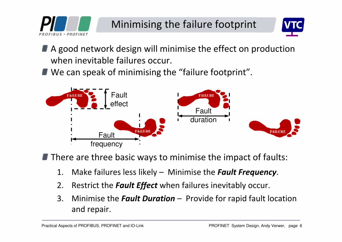
There are three basic ways to minimise the impact of faults:
1. Make failures less likely – Minimise the Fault Frequency.
2. Restrict the Fault Effect when failures inevitably occur.
3. Minimise the Fault Duration – Provide for rapid fault location
and repair.
A good network design will minimise the effect on production
when inevitable failures occur.
We can speak of minimising the “failure footprint”.
Fault
frequency
Fault
effectFault
duration

PROFINET System Design, Andy Verwer, page 7Practical Aspects of PROFIBUS, PROFINET and IO-Link
Minimising the failure footprint
Understand and implement the design and installation rules.
Improve reliability - use good quality well tested and reliable
devices, connectors and network components.
Use manufacturers who carry out burn-in testing on devices.
1. How can we minimise Fault Frequency?
Fault Frequency

PROFINET System Design, Andy Verwer, page 8Practical Aspects of PROFIBUS, PROFINET and IO-Link
Minimising the failure footprint
2. How can we minimise the Fault Effect?
Analyse the effects of failures on plant operation.
Use well thought out network layout and design.
Think about:
� Using separate networks or different controllers
(distributed control),
� Isolating sections of the network,
� Dealing with common cause failures.
Fault
Effect
PROFINET System Design, Andy Verwer, page 9Practical Aspects of PROFIBUS, PROFINET and IO-Link
Minimising the failure footprint
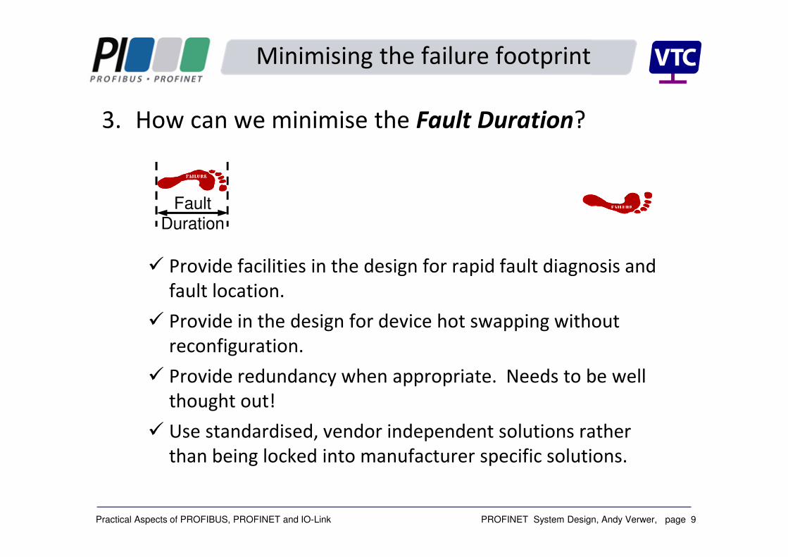
3. How can we minimise the Fault Duration?
� Provide facilities in the design for rapid fault diagnosis and
fault location.
� Provide in the design for device hot swapping without
reconfiguration.
� Provide redundancy when appropriate. Needs to be well
thought out!
� Use standardised, vendor independent solutions rather
than being locked into manufacturer specific solutions.
Fault
Duration
PROFINET System Design, Andy Verwer, page 10Practical Aspects of PROFIBUS, PROFINET and IO-Link
Minimising fault impact in design
Use pluggable devices that can be removed/replaced without
impinging on network operation.
Use appropriate network layout so that critical plant operation
can continue in the event of failure or device replacement.
Provide facilities for rapid troubleshooting and simple fault
isolation.
Use appropriate solutions for redundancy.
PROFINET System Design, Andy Verwer, page 11Practical Aspects of PROFIBUS, PROFINET and IO-Link
System Monitoring and Fault Finding
PROFIBUS systems have been around for over 25 years and
successful methods of health checking and troubleshooting
are well established. This is often based on the use of an
analyser with waveform visualisation facilities connected via a
piggy-back socket.
In the early days of PROFINET a similar approach was adopted
where an analyser (typically WireShark) is used to monitor
communications.
However, such methods are limited because:
We need a switch with a mirror port set up to monitor all
the traffic. Or an expensive “Tap” must be incorporated.
Further, such monitoring ports cannot be used for active
problem investigation.
1
1

PROFINET System Design, Andy Verwer, page 12Practical Aspects of PROFIBUS, PROFINET and IO-Link
System Monitoring and Fault Finding
A more modern approach is to incorporate
monitoring and engineering tools into the network at
the design stage.
These tools provide 24/7 remote monitoring and
active network access via a simple web-based
interface.
1
2
Softing’s TH Link
Indu-Sol’s
PROFINET
INspektorIba’s PROFINET
monitor

PROFINET System Design, Andy Verwer, page 13Practical Aspects of PROFIBUS, PROFINET and IO-Link
System Monitoring and Fault Finding
PROFINET systems can use unmanaged switches.
However, managed switches provide a number of major
advantages for engineering and trouble shooting on PROFINET
systems.
Managed switches can provide valuable network topology and
performance data that is centrally accessible using standard
engineering tools (via LLDP and SNMP).
1
3

PROFINET System Design, Andy Verwer, page 14Practical Aspects of PROFIBUS, PROFINET and IO-Link
The parts of a control system
will fail whilst in service.
The consequences of failures
are often predictable, but the
failures themselves are
unpredictable.
The design of a reliable
control system is not simple.
… and should be
accompanied by analysis of
how parts fail and of the
consequences of these
failures.
Cost of failures
PROFINET System Design, Andy Verwer, page 15Practical Aspects of PROFIBUS, PROFINET and IO-Link
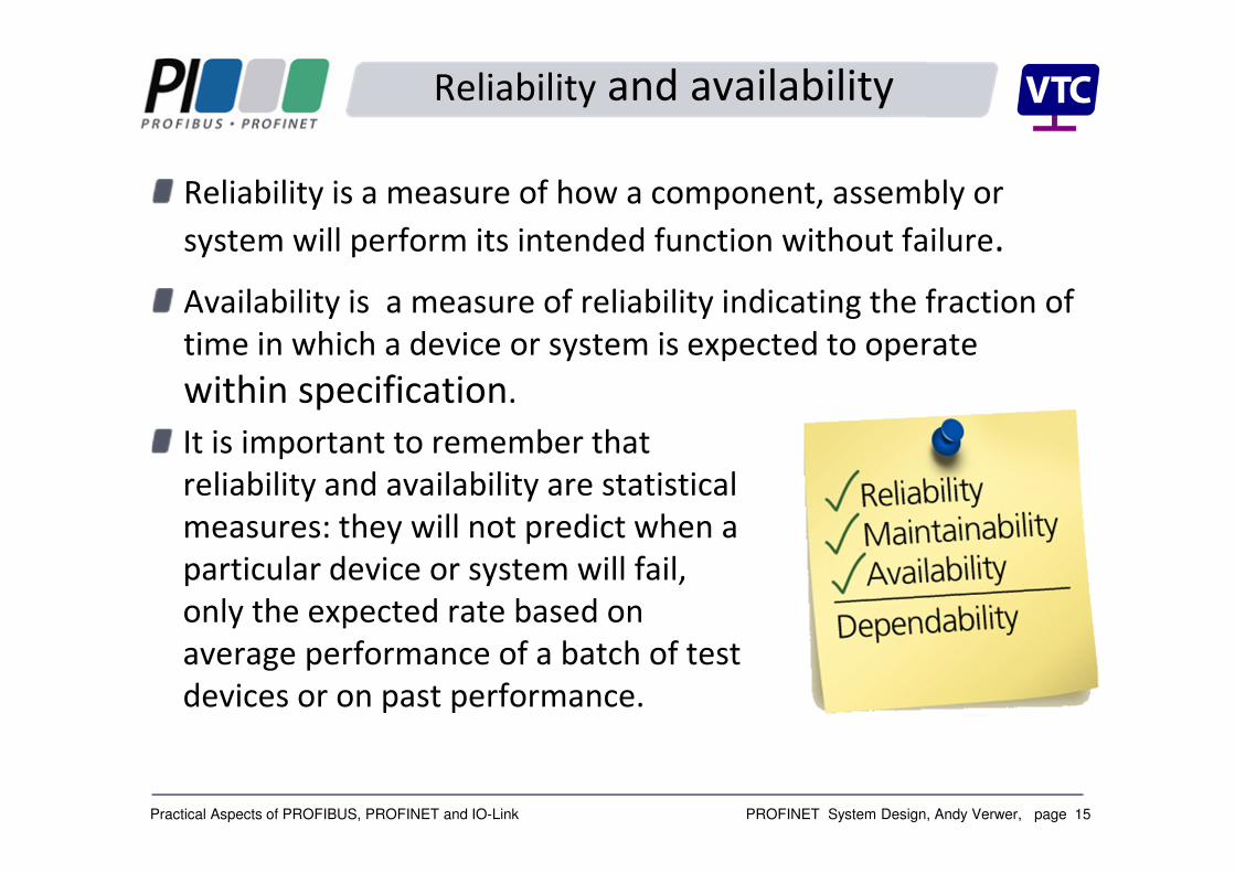
Reliability and availability
Reliability is a measure of how a component, assembly or
system will perform its intended function without failure.
Availability is a measure of reliability indicating the fraction of
time in which a device or system is expected to operate
within specification.
It is important to remember that
reliability and availability are statistical
measures: they will not predict when a
particular device or system will fail,
only the expected rate based on
average performance of a batch of test
devices or on past performance.
PROFINET System Design, Andy Verwer, page 16Practical Aspects of PROFIBUS, PROFINET and IO-Link
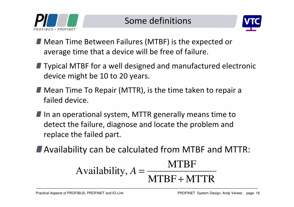
Some definitions
Mean Time Between Failures (MTBF) is the expected or
average time that a device will be free of failure.
Typical MTBF for a well designed and manufactured electronic
device might be 10 to 20 years.
Mean Time To Repair (MTTR), is the time taken to repair a
failed device.
In an operational system, MTTR generally means time to
detect the failure, diagnose and locate the problem and
replace the failed part.
Availability can be calculated from MTBF and MTTR:
MTTRMTBF
MTBF ty,Availabili
+
=A
PROFINET System Design, Andy Verwer, page 17Practical Aspects of PROFIBUS, PROFINET and IO-Link
Availability and downtime
Note that the availability of a device or system can be improved
by decreasing the MTTR.
This can be accomplished in several ways:
Faster detection and location of faults.
Accomplished by monitoring and fault reporting facilities.
Availability of fault finding tools.
Training of maintenance personnel.
Faster repair of the fault.
Accomplished by availability of spares and all of the
above.
Fault tolerant design achieved using well thought out
layout and design and/or redundancy where appropriate.

PROFINET System Design, Andy Verwer, page 18Practical Aspects of PROFIBUS, PROFINET and IO-Link
Example
Consider a device with a MTBF of 10 years.
When the device fails, it could take several days to
recognise, diagnose and locate the fault. And then, if not
held as a spare, several more days to obtain a replacement.
The MTTR could be one week, giving an availability of:
998.073650
3650
736510
36510=
+
=
+×
×=
+
=
MTTRMTBF
MTBFA
This represents a downtime of about 16 hours/year.
Consider the availability when the MTTR is reduced to ½ day:
0.999865.036510
36510=
+×
×=A
The downtime has reduced to about 1hour/year.

PROFINET System Design, Andy Verwer, page 19Practical Aspects of PROFIBUS, PROFINET and IO-Link
Reliability modelling
The system designer must understand the methods of
modelling and analysis of reliability and availability in systems.
In particular how system availability can be predicted from the
individual parts.
Also understand how standby systems, redundant solutions
and common cause failures impact the overall system
reliability.
We often find that redundancy is inappropriately used and
sometimes results in no real improvement in system
availability.
Careful network layout can have a major effect on the fault
footprint and significantly improve the overall availability of
the plant.

PROFINET System Design, Andy Verwer, page 20Practical Aspects of PROFIBUS, PROFINET and IO-Link
Standby and redundant systems
We often see standby or redundant systems used to try to
improve plant availability.
Here we have two or more devices working in parallel.
Should a fault occur in the operational device then the standby
device can take over.
The switch over can be manually activated or can be
automatic. The switching time should be considered when
estimating the overall system availability.
This scheme achieves high availability because the system
function is maintained whilst repairing the failed device.
PROFINET System Design, Andy Verwer, page 21Practical Aspects of PROFIBUS, PROFINET and IO-Link
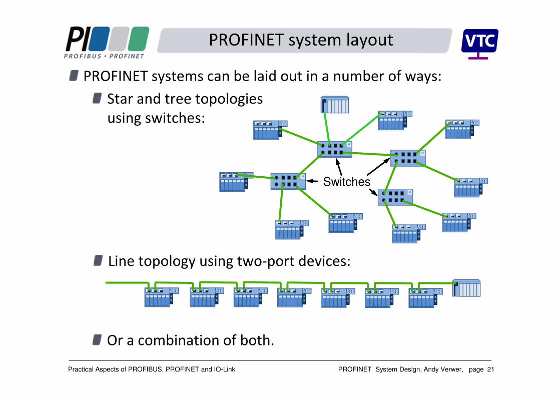
PROFINET system layout
PROFINET systems can be laid out in a number of ways:
Star and tree topologies
using switches:
Line topology using two-port devices:
Or a combination of both.
Switches

PROFINET System Design, Andy Verwer, page 22Practical Aspects of PROFIBUS, PROFINET and IO-Link
PROFINET system layout
There is a clear advantage of the star topology in terms of
system availability in that any device can be replaced without
affecting the other devices.
However, the system cost will be significantly greater because
of the number of switches required.
The line topology is much lower cost, because separate
switches are not required.
But removal or replacement of any device will cause all
downstream devices to fail.
In practice a cost effective solution is to appropriately combine
both topologies into your design. However, a proper risk and
effects study needs to be carried out.
PROFINET System Design, Andy Verwer, page 23Practical Aspects of PROFIBUS, PROFINET and IO-Link
Redundancy solutions for PROFINET
One of the big advantages of PROFINET is that it incorporates
a standard specification for media redundancy.
The standardised Media Redundancy Protocol (MRP) provides
manufacturer independent redundancy which can be used
over copper or fibre cables.
PROFINET redundancy can provide:
• Controller redundancy.
• Transmission media and switch redundancy.
• IO device redundancy.
Redundant PROFINET systems are relatively easy to implement
and can be used across different manufacturers.
PROFINET System Design, Andy Verwer, page 24Practical Aspects of PROFIBUS, PROFINET and IO-Link
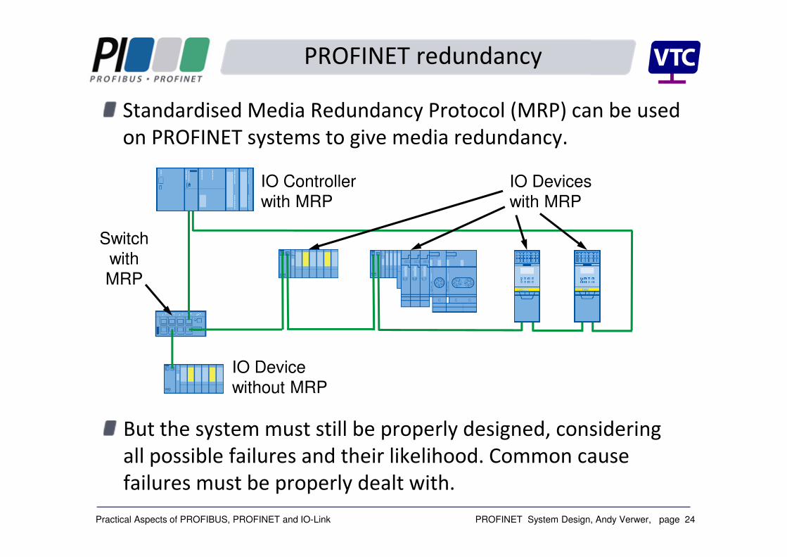
PROFINET redundancy
Standardised Media Redundancy Protocol (MRP) can be used
on PROFINET systems to give media redundancy.
IO Controller
with MRPIO Devices
with MRP
Switch
with
MRP
IO Device
without MRP
But the system must still be properly designed, considering
all possible failures and their likelihood. Common cause
failures must be properly dealt with.
PROFINET System Design, Andy Verwer, page 25Practical Aspects of PROFIBUS, PROFINET and IO-Link
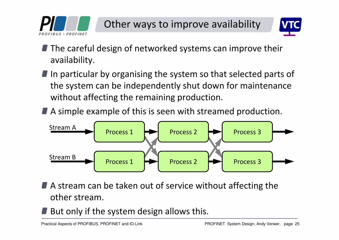
Other ways to improve availability
The careful design of networked systems can improve their
availability.
In particular by organising the system so that selected parts of
the system can be independently shut down for maintenance
without affecting the remaining production.
A simple example of this is seen with streamed production.
A stream can be taken out of service without affecting the
other stream.
But only if the system design allows this.
Process 1 Process 2 Process 3Stream A
Process 1 Process 2 Process 3Stream B

PROFINET System Design, Andy Verwer, page 26Practical Aspects of PROFIBUS, PROFINET and IO-Link
Certified System Design course
A new Certified PROFIBUS System Design course was
developed and accredited by PI last year.
This 2½-day training course is available at selected locations
and on-site at company’s premises. The course is suitable for
system designers, project managers and decision makers.
Plans are in place to develop a Certified PROFINET System
Design course.

PROFINET System Design, Andy Verwer, page 27Practical Aspects of PROFIBUS, PROFINET and IO-Link
Training
Certified PROFIBUS and PROFINET training including the
Certified PROFIBUS System Design course is available from the
UK’s accredited training centres:
PROFIBUS International Competence Centre
Manchester Metropolitan University.
in Manchester, or a location of your choice.
(www.sci-eng.mmu.ac.uk/ascent/).
PROFIBUS International Training Centre
Verwer Training & Consultancy Ltd
In Manchester or on-site.
(www.VerwerTraining.com)