professional surveillance system
DESCRIPTION
User ManualTRANSCRIPT

Professional Surveillance System
User’s Manual
Version 4.02
10125 NW 116th Way , Suite 5. Medley, FL 33178 Toll Free : 1.866.797.8XTSwww.xtscorp.com

2
Table of Contents
1 OVERVIEW AND ENVIRONMENT.....................................................................6
1.1 Overview ................................................................................................................................................6
1.2 Environment..........................................................................................................................................6
2 INSTALLATION AND UPGRADE.......................................................................7
2.1 Installation .............................................................................................................................................7
2.2 Un-installallation ................................................................................................................................ 102.2.1 Windows Menu ................................................................................................................................ 102.2.2 Start Menu........................................................................................................................................ 112.2.3 Resource CD ...................................................................................................................................11
2.3 Upgrade................................................................................................................................................ 112.3.1 Software of the same version........................................................................................................ 112.3.2 Software of different version.......................................................................................................... 13
3 INTERFACE......................................................................................................14
3.1 Login Interface ...................................................................................................................................14
3.2 Initialization Interface ....................................................................................................................... 14
3.3 Main Interface .....................................................................................................................................15
3.4 Interface Button .................................................................................................................................17
3.5 Video Control Zone ........................................................................................................................... 17
3.6 Screen Display Mode ........................................................................................................................ 18

3
3.7 Function Button .................................................................................................................................183.7.1 Task .................................................................................................................................................. 193.7.2 Alarm................................................................................................................................................. 193.7.3 Playback ........................................................................................................................................... 20
3.7.3.1 Device Record ....................................................................................................................... 203.7.3.2 Link Record (Activation Record) ......................................................................................... 203.7.3.3 Local Record .......................................................................................................................... 213.7.3.4 Download ................................................................................................................................ 213.7.3.5 Dav to Avi ............................................................................................................................... 22
3.7.4 E-map ............................................................................................................................................... 233.7.5 Configuration ...................................................................................................................................27
3.7.5.1 Password Modification .......................................................................................................... 273.7.5.2 Option ......................................................................................................................................27
3.8 Right Tool Bar ....................................................................................................................................303.8.1 Device List........................................................................................................................................ 303.8.2 PTZ Direction Control ..................................................................................................................... 323.8.3 PTZ Advanced .................................................................................................................................323.8.4 Tool ................................................................................................................................................... 34
3.8.4.1 Begin/Stop record plan ......................................................................................................... 343.8.4.2 NVD Control ........................................................................................................................... 343.8.4.3 Health Report ......................................................................................................................... 373.8.4.4 Log Query ............................................................................................................................... 383.8.4.5 Alarm Link Video (Alarm Activation Video) ........................................................................ 393.8.4.6 Color Configuration ............................................................................................................... 393.8.4.7 Volume ....................................................................................................................................39
3.8.5 Setting Manage ............................................................................................................................... 403.8.5.1 Scheme and Task (Task and Project) ................................................................................ 403.8.5.2 Record Plan Configuration ...................................................................................................433.8.5.3 Alarm Manage........................................................................................................................ 453.8.5.4 Alarm Record Plan ................................................................................................................ 483.8.5.5 E-map ......................................................................................................................................483.8.5.6 Decode Card Configuration .................................................................................................533.8.5.7 User Management ................................................................................................................. 543.8.5.8 Device Manager..................................................................................................................... 553.8.5.9 NVD Manage.......................................................................................................................... 573.8.5.10 SNVD Manage ....................................................................................................................... 583.8.5.11 User Configuration ................................................................................................................ 58
3.9 Device Health Status......................................................................................................................... 59
3.10 Full Menu ............................................................................................................................................. 603.10.1 Modify Password ........................................................................................................................ 603.10.2 Device .......................................................................................................................................... 603.10.3 Alarm ............................................................................................................................................ 603.10.4 Record Manage .......................................................................................................................... 613.10.5 Scheme Task .............................................................................................................................. 61

4
3.10.6 E-map........................................................................................................................................... 613.10.7 Configuration............................................................................................................................... 623.10.8 Log Query....................................................................................................................................623.10.9 Log out ......................................................................................................................................... 623.10.10 Exit................................................................................................................................................ 63
3.11 Tray Menu ............................................................................................................................................ 633.11.1 Modify Password ........................................................................................................................ 633.11.2 Alarm ............................................................................................................................................ 643.11.3 E-map View .................................................................................................................................643.11.4 Color Default Setup.................................................................................................................... 643.11.5 Scheme Task .............................................................................................................................. 643.11.6 Begin/Stop Record Plan ............................................................................................................ 643.11.7 Log Query....................................................................................................................................643.11.8 Close Alarm Sound .................................................................................................................... 643.11.9 Log out ......................................................................................................................................... 643.11.10 Exit................................................................................................................................................ 64
4 OPERATION INSTRUCTION............................................................................65
4.1 Monitor Operation ............................................................................................................................. 65
4.2 Monitor Task and Monitor Project .................................................................................................66
4.3 PTZ Control ......................................................................................................................................... 66
4.4 Playback............................................................................................................................................... 674.4.1 Device Record Playback ................................................................................................................ 674.4.2 Local Record Playback .................................................................................................................. 674.4.3 Download ......................................................................................................................................... 684.4.4 Record Play Control........................................................................................................................ 684.4.5 Others ............................................................................................................................................... 68
4.5 Snapshot and Manual Record ........................................................................................................ 68
4.6 E-map.................................................................................................................................................... 68
4.7 Log out ................................................................................................................................................. 68
5 PERIPHERAL DEVICE OPERATION............................................................... 70
5.1 Decode Card ....................................................................................................................................... 70
5.2 NVD ....................................................................................................................................................... 705.2.1 Menu ................................................................................................................................................. 705.2.2 NVD Control Principle .................................................................................................................... 705.2.3 Audio talk.......................................................................................................................................... 72

5
WelcomeThank you for using our Professional Surveillance System (PSS)!This user’s manual is designed to be a reference tool for operation of your system.Here you can find detailed operation information about PSS.

6
1 Overview and Environment
1.1 OverviewPSS is an abbreviation for Professional Surveillance System.It is software to manage small quantity security surveillance devices. It releases with the deviceand does not support the products from other manufacturers.It can view several camera channels from various devices, and it can view the recorded videofiles from various devices. PSS can support multiple scheduled arms to realize auto PC guard.PSS supports e-map; you can clearly view all device locations.It can create individual configuration files for each user, which allows you maintain your own habitand style.Please note, there is only one running PSS in one PC.The PSS can send out the device alarm information to the peripheral applications for extensionuse.
1.2 Environment OS: Windows 2000 / Windows XP / Windows 2003/ Windows Vista/Windows 7. CPU: 2.4GHz or higher. Display card: Independent car and support directX 8.0c or higher. Memory: 1GB or higher for XP OS. Displayer: 1024*768 or higher.

7
2 Installation and Upgrade
2.1 InstallationPlease check the installation CD and make sure it includes the following files:Setup.exe Pro Surveillance System.msiDouble click the setup.exe to begin installation. See Figure 2-1.
Figure 2-1
Click next button to go to installation interface. See Figure 2-2.
Figure 2-2
Click next button, you can see an interface is shown as in Figure 2-3. Please input user nameand organization name.

8
Figure 2-3
Click next button, you can see an interface is shown as below. Please select installation folder.Default folder is C:\Program Files\Pro Surveillance System\. See Figure 2-4.
Figure 2-4
Click next button, you can see there is an interface asking you to confirm the installation. SeeFigure 2-5.

9
Figure 2-5
Click next button, system begins installation. The interface is shown as in Figure 2-6.
Figure 2-6
During the installation process, you can click cancel button to exit.After installation, you can see an interface is shown as below. See Figure 2-7.

10
Figure 2-7
Click close button, you can complete the installation.
2.2 Un-installationThere are two ways for you to remove the PSS.2.2.1 Windows MenuFrom the control panel to the add/remove program, you can see an interface is shown as inFigure 2-8.
Figure 2-8
Click remove button, you can see a dialogue box is shown as in Figure 2-9.

11
Figure 2-9
Click Yes button to remove PSS.2.2.2 Start MenuFrom Start menu-> All programs->PSS, select PSS uninstall item.System pops up the following dialogue box. See Figure 2-10. Please click yes to remove PSS.
Figure 2-10
2.2.3 Resource CDYou can click the PSS Setup.ms in the installation CD, system pops up the following dialoguebox.Please select remove PSS item to delete it. See Figure 2-11.
Figure 2-11
2.3 Upgrade2.3.1 Software of the same version

12
If there is PSS software of the same version in the PC, you can see a dialogue box is shown asin Figure 2-12. Please click repair PSS setup to update the PSS.
Figure 2-12
During the repair process, the interface is shown as in Figure 2-13.
Figure 2-13
During the process, you can click cancel button to exit.After installation, you can see an interface is shown as below. See Figure 2-14.

13
Figure 2-14
Click close button, you can complete the installation.
2.3.2 Software of different versionIf your PC has installed different version, please uninstall the PSS first and then install the latestversion. For detailed installation steps, please refer to chapter 2.1 Installation.

14
3 Interface
Double click PSS icon , you can go to the login interface.
3.1 Login InterfaceLogin interface is shown as in Figure 3-1. User name: Input the user account Password: Please input corresponding password to log in. OK: Click this button, system can verify the account and then enter the software main
interface. Cancel: Click this button to exit login interface.Note: If it is your first time to run the PSS program, default user name is admin. Admin is a super
administrator and can not be removed. It can add, modify or delete other user. For security reason, please modify your password after first log in. You can memory your password, so that when you can log in the next time, you do not need
to input user name and password. Please note this function is for your convenient only. Donot enable this function in public PC.
Figure 3-1
3.2 Initialization InterfaceClick OK button, system begins verifying user name and password and then go to theinitialization interface. See Figure 3-2.Please note it may take a little bit longer to initialize decode card, please be patient.If it is your first time to use PSS, please go to chapter 3.7.5.2 Option to implement setup.

15
Figure 3-2
3.3 Main InterfaceIn the main interface, there are real-time monitor interface and other operation and function menu.See Figure 3-3.
Figure 3-3
1 2 3
4 5 6

16
Section 1: Current display window. It is circled by a green boundary. For video controlinformation, please refer to chapter 3.5 Video control zone.
Section 2: Right tool bar. Here you can view the five buttons: Device list (chapter 3.8.1).PTZdirection (Chapter 3.8.2), PTZ advanced (chapter 3.8.3), Tool (chapter 3.8.4), SettingManage (chapter 3.8.5).
Section 3: There are five buttons. Lock/Close/Minimize/Switch/Full menu. Forclose/Minimize/Switch button information, please refer to chapter 3.4 interface button. Clickfull menu button; you can view a menu tree shown as in Figure 3-4. For detail full menuinformation, please refer to chapter 3.11.
Figure 3-4
Section 4: Screen display mode. Please refer to chapter 3.6 for detailed information. Section 5: Function buttons. Here you can view the following buttons: Task (chapter 3.7.1),
Alarm (chapter 3.7.2), Playback (chapter 3.7.3), E-map (chapter 3.7.4), and Configuration(chapter 3.7.5).
Section 6: Device health status. Please refer to chapter 3.9 for detailed information.When PSS is running, you can also see there is a littlie icon on your right tray menu. See Figure3-5.
Figure 3-5
Right click mouse, you can see an interface is shown as in Figure 3-6.Please go to chapter 3.11 for detailed tray menu information.
Figure 3-6
17
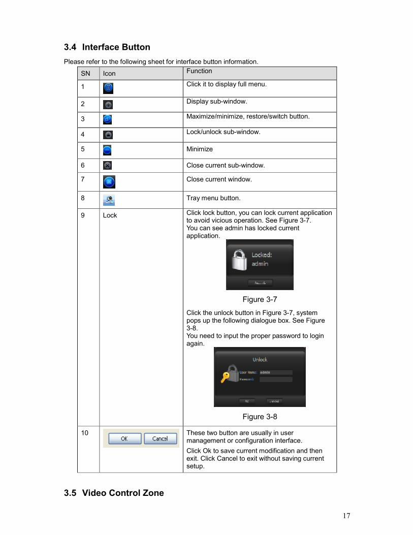
3.4 Interface ButtonPlease refer to the following sheet for interface button information.
SN Icon Function
1 Click it to display full menu.
2 Display sub-window.
3 Maximize/minimize, restore/switch button.
4 Lock/unlock sub-window.
5 Minimize
6 Close current sub-window.
7 Close current window.
8 Tray menu button.
9 Lock Click lock button, you can lock current applicationto avoid vicious operation. See Figure 3-7.You can see admin has locked currentapplication.
Figure 3-7
Click the unlock button in Figure 3-7, systempops up the following dialogue box. See Figure3-8.You need to input the proper password to loginagain.
Figure 3-8
10 These two button are usually in usermanagement or configuration interface.Click Ok to save current modification and thenexit. Click Cancel to exit without saving currentsetup.
3.5 Video Control Zone

18
On the video upper right, there are six icons. See Figure 3-9.
Figure 3-9
Please refer to the following sheet for detail information.
1 Digitalzoom
Click this button and then left drag the mouse in the zone tozoom in. Right click mouse system restores original status.
2 Changeshowmode
Resize or switch to full screen mode. You can double clickmouse to change the mode.
3 Localrecord
When you click local record button, the system begins recording.The recorded file is saved to system folder.
4 Capturepicture
You can snapshoot important video. All images are memorized insystem folder.
5 Audio Turn on or off audio.(It has no relationship with system audiosetup )
6 Closevideo
Close video in current window.
3.6 Screen Display ModeScreen display mode interface is shown as in Figure 3-10.
Figure 3-10
From the left to the right, there are video quality, real-time/fluent button, full-screen button and 1-36 screen modes.Note:In full-screen mode or the window is maximized, sometimes you may notice the height and widthof small window can adjust according to the displayer.
3.7 Function ButtonFunction button is show as in Figure 3-11.It consists of the five buttons: Task/Alarm/Playback/E-map/Config.
12 3 4 5 6
1 2 3 4

19
Figure 3-11
3.7.1 TaskClick Task button, the interface is shown as below See Figure 3-12.Here you can enable/disable the task or project item.Pause/restore button: Once you enabled one task/project, system display pause button.Circle means current task is in progress.
Figure 3-12
3.7.2 AlarmAlarm manage interface is shown as in Figure 3-13.
Figure 3-13
Please refer to the following sheet for detail information.SN Name Function1 Alarm Type The alarm consists of xis
types: All alarms/Externalalarm/Motion detection/Videoloss/Camera masking/other
20
alarms.
2 All Devices You can select a device fromthe dropdown list.
3 Alarm record You can see alarm time andalarm detail information.
Please go to chapter 3.7.5.2 Option to set “alarm record max amount”. Once the record is full,system automatically overwrites the previous one.In chapter 3.7.5.2 Option, you can also set alarm information management operation.
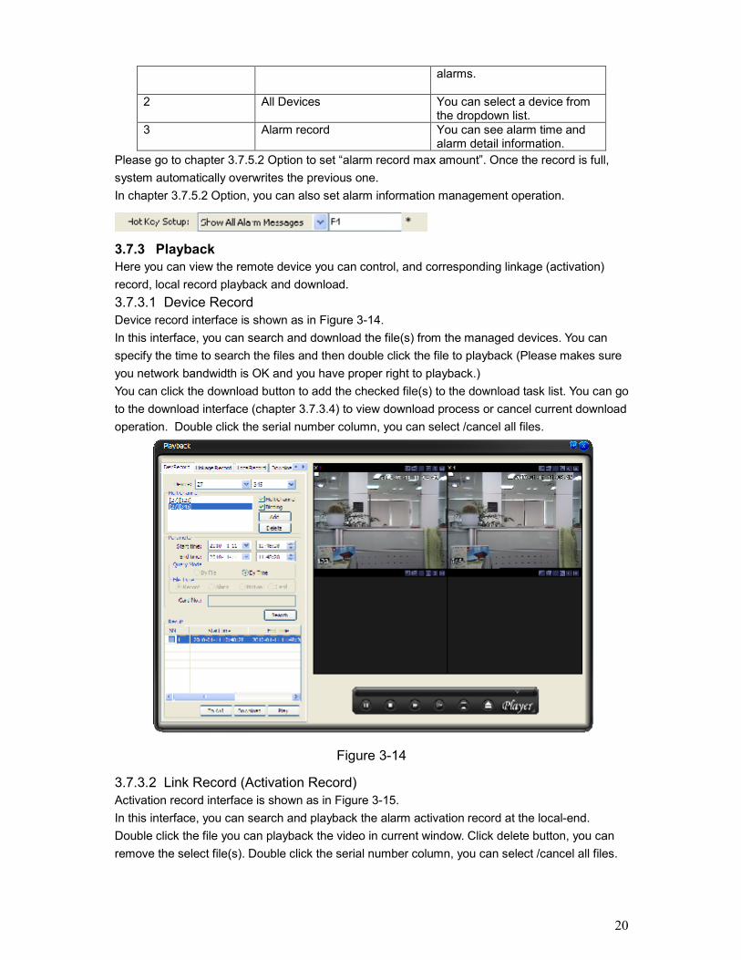
3.7.3 PlaybackHere you can view the remote device you can control, and corresponding linkage (activation)record, local record playback and download.3.7.3.1 Device RecordDevice record interface is shown as in Figure 3-14.In this interface, you can search and download the file(s) from the managed devices. You canspecify the time to search the files and then double click the file to playback (Please makes sureyou network bandwidth is OK and you have proper right to playback.)You can click the download button to add the checked file(s) to the download task list. You can goto the download interface (chapter 3.7.3.4) to view download process or cancel current downloadoperation. Double click the serial number column, you can select /cancel all files.
Figure 3-14
3.7.3.2 Link Record (Activation Record)Activation record interface is shown as in Figure 3-15.In this interface, you can search and playback the alarm activation record at the local-end.Double click the file you can playback the video in current window. Click delete button, you canremove the select file(s). Double click the serial number column, you can select /cancel all files.

21
Figure 3-15
3.7.3.3 Local RecordLocal record interface is shown as in Figure 3-16.Here you can search and playback all files at the local-end. Double click the file name you canopen the video in current window. If you select the image file, then system open the image. Clickdelete button, you can remove the select file(s). Double click the serial number column, you canselect /cancel all files.
Figure 3-16
3.7.3.4 DownloadDownload interface is shown as in Figure 3-17.

22
In this interface you can see the download task process and record file information. You can clickstop button to cancel current operation.
Figure 3-17
3.7.3.5 Dav to AviDav to AVI interface is shown as in Figure 3-18.In this interface, you can convert the Dav file to AVI file so that these recorded files can play ingeneral player.
Figure 3-18
Please refer to the following sheet for detailed information.
Parameter Function
Type Search general record, alarm record, motion detectionrecord and card record.

23
Parameter Function
Alarm Search alarm record.
MotionDetection
Search motion detection record.
Card Search card record.
Start time Set the file start time.
End time Set the file end time.
Channel Select the channel from the dropdown list.
Search Click this button you can view the recorded file matchedyour requirements.
Playback Select the file first and then click playback button to viewthe video.Double click serial number (SN) column you can select tall files.
Downloadtype
Download by file: Select the file(s) and then clickdownload button.
Download by time: Download the recorded file(s) withinyour specified period.
Download Select the file you need (multiple choices) and thenclick download button, you can see system pops up adialogue box, please specify file name and path todownload the file(s) to your local pc.
Input the downloaded file name, specify the path andthen click OK button. You can see system beginsdownload and the download becomes stop button.There is a progress bar for your reference.
Linkagerecord
You can search the alarm activated record in the localend. Double click the file name you can open the video incurrent window.
Localrecord
Select local record to play.Double click serial number (SN) column you can selectall files.
Please note, for playback function, sometimes, due to network factor or device right factor, youcan not playback some files.Please note record save path and download save path are not the same. Please refer to chapter3.7.5.2 Option.
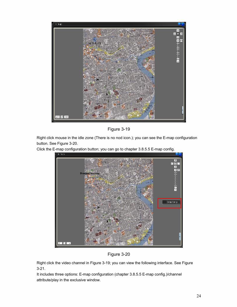
3.7.4 E-mapClick E-map button, the interface is shown as in Figure 3-19.
24
Figure 3-19
Right click mouse in the idle zone (There is no nod icon.); you can see the E-map configurationbutton. See Figure 3-20.Click the E-map configuration button; you can go to chapter 3.8.5.5 E-map config.
Figure 3-20
Right click the video channel in Figure 3-19; you can view the following interface. See Figure3-21.It includes three options: E-map configuration (chapter 3.8.5.5 E-map config.)/channelattribute/play in the exclusive window.

25
Figure 3-21
Click channel attribute, you can see the device name and channel title. See Figure 3-22.
Figure 3-22
Click the play in exclusive window; you can see the system pops up the following window todisplay the video. See Figure 3-23.
Figure 3-23

26
On the top right, there are five direction keys. . You can click it to move e-map
position. The centre button is to go to the e-map centre. It is valid when e-map is zooming in.
The left button is to view previous browser image and the next browser image.
The middle button is to go back to the main e-map and clear browser history.Double click sub e-map to go to the next e-map. Double click camera to open the monitor video.
Figure 3-24
In Figure 3-24, you can see you can use the buttons to zoom in or zoom out the e-map. Roll themouse you can also zoom the e-map.In Figure 3-24, click the button on the top right, system pops up the node information. Here youcan view the e-map organization and its node information. See Figure 3-25.
Figure 3-25
On the bottom right, there is a small e-map button (See Figure 3-26). You can click it to displayor hide the small e-map. System hides the button when it is to display the small e-map. You canleft click the e-map to display the button again.System displays a red circle in the small e-map to represent the node. The green column in thesmall e-map is to represent the current displayed zone.
Click here you can view the nodeinformation (Figure 3-15).

27
Figure 3-26
If you have armed the camera or alarm channel, when alarm occurs, the corresponding cameraor alarm device will flash.For detailed E-map setup and implement, please refer to chapter 3.8.5.5 E-map.
3.7.5 ConfigurationClick Config button, you can see an interface is shown as below. See Figure 3-27.
Figure 3-27
3.7.5.1 Password ModificationClick password modification button, system pops up the following interface. See Figure 3-28.
Figure 3-28
Please input the old password and then input new password twice to change the password.3.7.5.2 OptionClick option button, the interface is shown as in Figure 3-29. System basic setup Language: PSS support various languages. Please select from the dropdown list. Login all devices: User automatically logged in all devices after PSS booted up. Load decode card when system boots up: Load the decode card automatically after you
logged in.
Click the button here to display orhide the small e-map.
Here is to represent the displayedzone. The red icons are the nodes.

28
Auto start record plan: System automatically enables all record plans once you logged in. Auto pop up alarm information dialogue box: PSS pop up the alarm recode when alarm
occurred. Auto login the PSS: When PSS booted up, system uses the previous account to login the
PSS. Auto runs PSS when system boots up: After you PC completely booted up, system
automatically runs PSS. Hotkey Setup: Here you can set hot key for the operation button. Please note system default
debug hot key is F12. Do not set the debug key when you set the hotkey button. Displayed items in the right bar: System show which operation button by default. Preview picture: Open image mode when preview. If you check the box, then the picture will
be displayed in the system default program. If you do not check the box then it will displayedin the PSS.
Display alarm item in the interface: Here you can specify you most concern alarm items.Please refer to chapter 3.9 device health status for detail information.
Automatically register service listening port: You can input listening port value here. Get all devices health report enable: You can check the box to get all devices health report
(chapter 3.8.4.3.. Record basic setup Snapshot picture path: You can specify image save default path. Device free minimum space (MB): You can specify a value here. Once the capacity reaches
the specified threshold, system can stop record. Picture file name rule: You can specify image name rule in the dialogue box. Record Time (M): Please select from the dropdown list. Recorded file path: You can specify the file save path. Recorded file name rule: You can specify file name rule in the dialogue box. Downloaded file path: You can specify the download file Auto start monitor setup Auto start project: The project to be run. Project name: please input the project you wan to run automatically. Auto start task: The task to be run. Task name: Please input the task you wan to run automatically. Last run: The previous task and project will become active after you successfully logged in
the PSS. Save last monitor status: System will restore the previous monitor status when it boots up
the next time. Synchronization time setup Auto synchronizes the PC time to the device: System automatically synchronizes the time of
the front-end device. Sync time: You can set the time for the synchronization function operation. (Please make
sure you have enabled synchronization function.) Auto restart device: Once the local PC time is earlier than the front-end device time, after the
synchronization, front-end device needs to reboot to get the new time activated. Alarm record basic setup Alarm record max amount: Motion detection alarm display the max save records.

29
Refresh interval: Here you can specify device health status update interval. Please refer toChapter 3.9 device health status.
Use pop-up window for alarm activation video: Once you check the box, system will pop upa new window to display the alarm activation video (not in the main interface). Please referto chapter 3.8.4.5 alarm activation video for detail information.
Alarm video window amount: You can specify the window amount for the pop-pup alarmactivation video window. Please refer to chapter 3.8.4.5 alarm activation video for detailinformation.
Add disarming alarm message to the alarm record: Enable this function, system can add thedisarming alarm message to the alarm record interface. Otherwise, system only displays thearmed alarm message.
Alarm information output port: After you checked the box here, all the alarm information fromthe devices will be communicated with the peripheral applications via the port you set here.
Figure 3-29
Note:You need to reboot the system to activate the items with *!Click OK button, you can see a dialogue box shown as in Figure 3-30.Click Ok to reboot the PSS.
Figure 3-30

30
3.8 Right Tool BarSystem right tool bar is shown as in Figure 3-31.
Figure 3-31
3.8.1 Device ListHere you can view all the devices information you can configure. All logged in device channelhave open. See Figure 3-32.
Figure 3-32
Select one device and then right click mouse, you can see device operation menu. It consists offour items: Log out/attribute/Audio talk mode/Advance. Please note the audio talk format andadvanced is valid for logged in device only. Log out: log out current device. Attribute: Here you can view some basic device information such as title, IP and etc. See
Figure 3-33.

31
Figure 3-33
In Figure 3-33, check the “Show device running status” item, the interface is shown as below.See Figure 3-34.
Figure 3-34
Important
Once you have checked the in Option interface (Chapter
3.7.5.2 Option), you can not enable function here.
Audio talk format: System pops up the audio encode mode it supported. You can select theaudio encode mode. The circle means there is audio talk in process. You can also right clickmouse in one window to select the audio talk mode system supported.
Advanced: It consists of synchronization PC/reboot/Device configuration. Synchronization device time: it is to synchronize device time with the PC. Reboot: It is to reboot current device.

32
Device configuration: Please refer to corresponding device user’s manual forconfiguration information. Please note SVR does not support configuration function.
ImportantPlease note one device supports only one audio talk operation. Once you have enabled audiotalk function in decode device, you can not enable audio talk in device operation.Audio talk mode G711U is for special device only.
3.8.2 PTZ Direction ControlIf you want to use PTZ function, please make sure: Current device has PTZ function. You have proper right to control the PTZ.If you still can not use PTZ function, please check device PTZ protocol is right or not.
Click the lock icon , the PTZ interface becomes independent and can overlay the specified
screen as you desire.The PTZ direction interface is shown as in Figure 3-35.The step value ranges from 1 to 8. There are eight direction keys.In the middle of the eight direction arrows, Click this button, system goes back to the singlescreen mode. Drag the mouse in the screen to adjust section size. When the mouse move fromthe up to the down, you can see the screen zoom in. When the mouse from the down to the up,you can see the screen zoom out. Please note you need to use mouse to operate this function.Here is a sheet for you reference.
Name Functionkey
function Function key
function
Zoom Near FarFocus Near FarIris close Open
Figure 3-35
3.8.3 PTZ AdvancedClick PTZ advanced, the interface is shown as in Figure 3-36.
3D intelligent Positioningbutton

33
Figure 3-36
Parameter FunctionScan Click auto scan button, the interface is shown as below.
You can set scan left limit and right limit and then start a scan.Move the camera to you desired location and then click left limitbutton.Then move the camera again and then click right limit button to set aright limit.
Preset Use direction keys to move the camera to your desired location andthen input preset value. Click add button, you have set one preset.
Tour Click auto tour button, the interface is shown as in below.
Input auto tour value and preset value. Click add button, you haveadded one preset in the tour.Repeat the above procedures you can add more presets in one tour.Or you can click delete button to remove one preset from the tour.

34
Parameter FunctionPattern Click pattern button, the interface is shown as below.
You can input pattern value and then click start record button tobegin PTZ movement. Please implement camera operation. Thenyou can click stop record button. Now you have set one pattern.
Aux For some special functions, you need to use Aux button.System can return aux enable/disable command to the front-endPTZ device.
Flip For camera supports flip function, system can turn video upsidedown and then collect.
Light For most fixed cameras, it has its own light.
Wiper For most fixed cameras, it has its own wiper.
3.8.4 ToolClick tool button, you can see the following interface. See Figure 3-37.
Figure 3-37
3.8.4.1 Begin/Stop record planAfter you set the record plan, you can click this button to enable it. Once there is running recordplan, the item becomes “stop record plan” button.
3.8.4.2 NVD ControlNVD is a product of our company. You can use NVD to output the video to the video wall orother devices. The interface is shown as in Figure 3-38.It consists of five sections. Section 1: NVD device list. Section2: It consist of two buttons:

35
Log in/Log out: You can click it to log in or log out the device. NVD manage: Please refer to Chapter 3.8.5.9 for NVD manage information.
Section3: Video device list. Open the video and then drag the corresponding channel to thedecoder output channel, the decoder can output the video from current channel to thespecified device.
Section 4: NVD operation consists of three sections: operation, tour and decode tour. All theoperations become active when NVD is running normally.
Section5: It is decoder control zone. It is the four output channels. You can double click sub-window to switch to 1/4 window display mode.
Figure 3-38
TourClick the tour button, the interface is shown as below. See Figure 3-39. Search: Search the selected TV output tour setup of current NVD device. Add: Add current tour information to the TV output channel of current device. Delete: Click it to remove the selected tour setup information. Delete all: Click it to remove all tour setups of current TV output channel. Tour: Click it to begin the tour setup. Interval: The operation interval between the tour setups.
②
①
③
④
⑤

36
Figure 3-39
Decode TourClick decode tour button, the interface is shown as in Figure 3-40. NVD device: Here you can view the NVD device you selected from the NVD device tree. Decode channel: Here you can select the decode tour channel of the NVD device. Stay time (s): Here you can select the interval between the decode tour. It is the video stay
time in each channel. Video channel: You can drag the video channel on the left corner to the column here and
then release to set the video channel information. Add: Click it a odd current video channel tour information to the list. Update: Update the list to the latest information. Cancel: Restore the video channel information. Do not save current modification. Delete: Click it to delete the selected item in the list. Delete all: Click it to delete all the items in the list. Save: Save the latest setup information in the remote NVD device. Pause: Pause the decode tour operation of the remote NVD device. Resume: Restore the decode tour operation of the remote NVD device. Stop: Stop the decode tour operation of the remote NVD device. Start: Begin the decode tour operation of the remote NVD device.

37
Figure 3-40
3.8.4.3 Health ReportPlease note, you need to go to chapter 3.7.5.2 Option to check the “Get all devices health reportenable”. Otherwise you can not see the following interface.Health report interface is shown as below. See Figure 3-41.There are four sections. Section1: Detail running information of all devices. Section2: Once you enable auto refresh function, system can auto update list regularly. Section3 Refresh: Click refresh button to view latest running status. Export: click it to export current running status to the specified file. Section4: Record status icon samples.
38
Figure 3-41
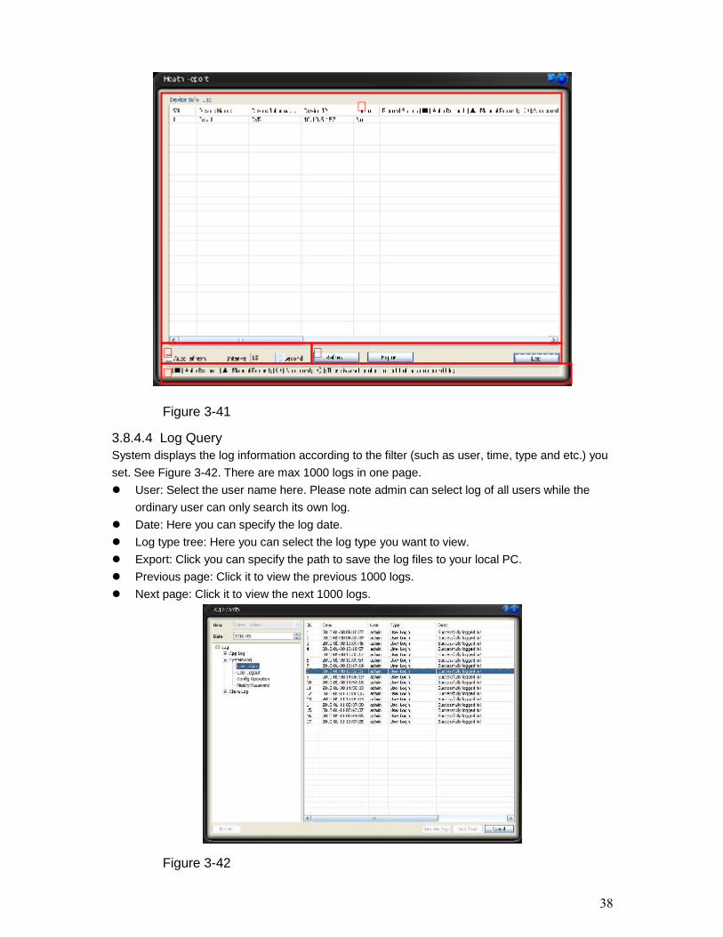
3.8.4.4 Log QuerySystem displays the log information according to the filter (such as user, time, type and etc.) youset. See Figure 3-42. There are max 1000 logs in one page. User: Select the user name here. Please note admin can select log of all users while the
ordinary user can only search its own log. Date: Here you can specify the log date. Log type tree: Here you can select the log type you want to view. Export: Click you can specify the path to save the log files to your local PC. Previous page: Click it to view the previous 1000 logs. Next page: Click it to view the next 1000 logs.
Figure 3-42
①
② ③④

39
3.8.4.5 Alarm Link Video (Alarm Activation Video)Please note the following interface is a pop-up window to display the alarm activation video. SeeFigure 3-43.
Figure 3-43
Please go to chapter 3.7.5.2 Option to enable this function and set the corresponding windowamount.See
If current function is invalid, the alarm activation video is displayed in the main window.
3.8.4.6 Color ConfigurationColor setup interface is shown as in Figure 3-44.You can click default button to restore default color setup.Please note, color setup function only applies to the selected video.
Figure 3-44
3.8.4.7 VolumeThe volume interface is shown as in Figure 3-45.There are three function buttons:Sound box volume control, microphone volume control and close alarm audio.
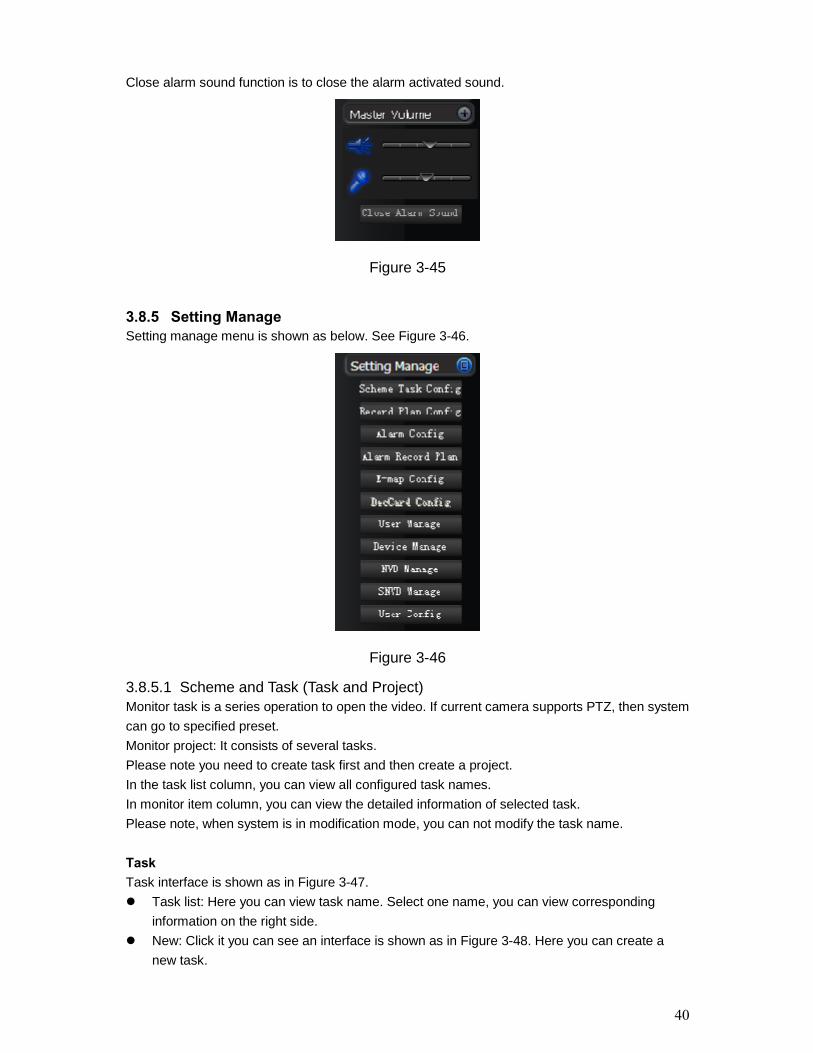
40
Close alarm sound function is to close the alarm activated sound.
Figure 3-45
3.8.5 Setting ManageSetting manage menu is shown as below. See Figure 3-46.
Figure 3-46
3.8.5.1 Scheme and Task (Task and Project)Monitor task is a series operation to open the video. If current camera supports PTZ, then systemcan go to specified preset.Monitor project: It consists of several tasks.Please note you need to create task first and then create a project.In the task list column, you can view all configured task names.In monitor item column, you can view the detailed information of selected task.Please note, when system is in modification mode, you can not modify the task name.
TaskTask interface is shown as in Figure 3-47. Task list: Here you can view task name. Select one name, you can view corresponding
information on the right side. New: Click it you can see an interface is shown as in Figure 3-48. Here you can create a
new task.

41
Modify: Modification interface is shown as in Figure 3-48. Please note you can not edit taskname.
Delete: You can click it to remove one task. Import: You can import task from specified XML file. Export: You can export current task to a XML file.
Figure 3-47
Task edit interface is shown as in Figure 3-48. Task Name: Please input task name here if you want to create a new task. Please note, if
you are going to edit the task. You can not modify the name. Window amount: Here you can input the window amount you want to see in the monitor
interface when you enabled current task. Window: Window serial number. It means the current monitor item is in which window. Camera name (can not be modified.) and camera ID: You can drag the channel name in the
device list section to the current column. Stay time(s): You can input stay value here. Preset: When you open the monitor, system can go to the specified preset. The default
preset value is N/A Bit stream type: if device supports extra stream, you can set the bit stream when open the
video. Monitor item: Here you can view task detail information. System begins task from number 1
to number 2 and then go on. You can use Up/Down button to adjust the monitor tasksequence.

42
Figure 3-48
ProjectMonitor project interface is shown as in Figure 3-49. Project list: Here you can view all set project names. Project item: Here you can view selected task detailed information. New: Click it you can see an interface is shown as in Figure 3-50. Here you can create a
new project. Modify: Modification interface is shown as in Figure 3-50. Please note you can not edit
project name. Delete: You can click it to remove one project. Import: Import the saved project XML file to current list. Export: Export current project list to specified xml file.
Figure 3-49

43
Click modify button, the interface is shown as in Figure 3-50.Please note, in modification mode, you can not modify project name. Monitor project name: Current project name (you can modify project name when adding a
new project.) Task name: Please select the task to be run. Start time: Please select the task start time. Up and down button is to adjust the monitor task sequence.Please click save button to exit.
Figure 3-50
3.8.5.2 Record Plan ConfigurationThe record manage interface is shown as below. See Figure 3-51. Pack duration (m): System can generate a recorded file when record plan is running. You
can input pack duration here. Record plan list: The record schedule in the record plan.In the below, you can view the valid record period of current camera.Double click time bar or the list column, you can modify schedule period for current camera.Please note, if you want to modify the plan, you can not modify the device information andchannel information

44
Figure 3-51
Edit Schedule TemplateIn Figure 3-51, click edit schedule template, you can see an interface is shown as below. SeeFigure 3-52.You can select schedule template here. Please note you can not modify or remove emptytemplate/all day template.You can view detail template information on the left side.
Figure 3-52
In Figure 3-51, click add button, the interface is shown as in Figure 3-53. Device: You can select from the dropdown list. Channel: You can select from the dropdown list. “<-one week” is to apply the selected schedule setup to the whole week. “<-” is to apply the selected schedule to the corresponding date(Sun to Sat.)You can select one template on the right and then click edit schedule template button to modify it.

45
Figure 3-53
3.8.5.3 Alarm ManageHere you can set corresponding alarm setup. You can go to chapter 3.7.5.2 Option to set themax alarm record amount. See Figure 3-54.
Figure 3-54
Global ConfigurationGlobal Configuration interface is shown as in Figure 3-54. Enable sound: Please draw a circle to enable sound function and then click browser button
to select corresponding sound file. Add to alarm manage: Display in alarm information window: You can enable this function to
add alarm message to alarm record window (Chapter 3.7.2 Alarm).

46
Alarm activation has the higher priority: Please note once there is new alarm, alarmactivation video will be switched to display the new one no matter the previous alarm displayinterval is over or not. You can check the box to enable current function.
Modify the amount of the video window when alarm activates the video: When the alarmactivation window index is more than the monitor window amount, system cam automaticallychange the window amount to display the activation video.
Alarm arm enable: You can enable this function to use alarm setup. Otherwise the alarmsetup is null.
Import/Export: Import/export the global configuration to current interface( XML file),
Arm/DisarmArm/disarm interface is shown as in Figure 3-55.The arm has four types: Motion detection/video loss/Camera masking/External alarm.You can select corresponding setup to the specified channel.
Figure 3-55
Activation Strategy
Activation interface is shown as below. See Figure 3-56.
Alarm device: In the alarm device list, you can view the alarm sourcing device. You can setseveral activation operations for one alarm sourcing device.
Type: You can select the activated alarm type from the dropdown list. Resume previous video after alarm ended: The activation alarm can open the video in the
specified window. The video stays for the specified time and then restore previous video.
Display alarm prompt in the video window: The icon pops in current alarm windowwhen alarm occurs. (On the top left).
Channel: You can select the activated channel when alarm occurs.
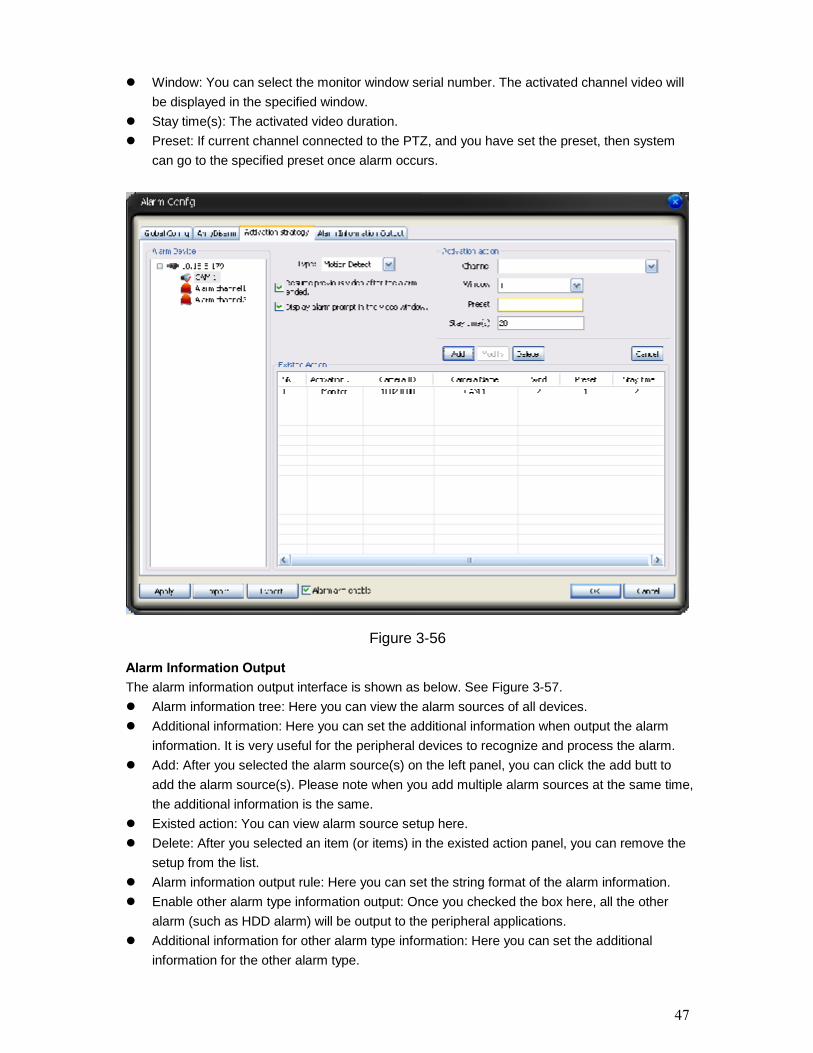
47
Window: You can select the monitor window serial number. The activated channel video willbe displayed in the specified window.
Stay time(s): The activated video duration. Preset: If current channel connected to the PTZ, and you have set the preset, then system
can go to the specified preset once alarm occurs.
Figure 3-56
Alarm Information OutputThe alarm information output interface is shown as below. See Figure 3-57. Alarm information tree: Here you can view the alarm sources of all devices. Additional information: Here you can set the additional information when output the alarm
information. It is very useful for the peripheral devices to recognize and process the alarm. Add: After you selected the alarm source(s) on the left panel, you can click the add butt to
add the alarm source(s). Please note when you add multiple alarm sources at the same time,the additional information is the same.
Existed action: You can view alarm source setup here. Delete: After you selected an item (or items) in the existed action panel, you can remove the
setup from the list. Alarm information output rule: Here you can set the string format of the alarm information. Enable other alarm type information output: Once you checked the box here, all the other
alarm (such as HDD alarm) will be output to the peripheral applications. Additional information for other alarm type information: Here you can set the additional
information for the other alarm type.

48
Figure 3-57
3.8.5.4 Alarm Record PlanAlarm record plan interface is shown as in Figure 3-58.Here you can set various alarm activation record for he same arm period. You can use theschedule template to set continently. You can view there is a circle for the selected channel.Please go to playback interface to search the alarm record (chapter 3.7.3 Playback-linkagerecord.).
Figure 3-58
3.8.5.5 E-map

49
System provides three modes to display E-map node: Thumbnail /Device tree/E-map.If it is you first to use e-map, you need to create one first. Please refer to chapter 3.7.5.2 Optionfor e-map loading path.The e-map interface is shown as below. See Figure 3-59.
Figure 3-59
In Figure 3-59, click picture edit button, you can see the following interface. See Figure 3-60.
Figure 3-60
Click add button, you can see an interface is shown as in Figure 3-61. Here you can input picturename (such as Shanghai Map), picture description and then select picture path. Please click OKbutton to save current setup.
Preview
E-map List
E-map Display Window

50
Figure 3-61
After you completed the above steps, the interface is shown as below. See Figure 3-62.Please click OK to exit.
Figure 3-62
Now please click picture button, then you can see you have added an e-map. See Figure 3-63.
Figure 3-63

51
In Figure 3-63, left click e-map name and then drag it to the display section. Now you can see aninterface is shown as in Figure 3-64.
Figure 3-64
In Figure 3-64 click device button, and then drag the channel number to the e-map and thenrelease. You can see the following interface. See Figure 3-65.You can see you have added a camera in the e-map (CAM4)
Figure 3-65
Click device button here.
Select a camera here.Drag your mouse to the e-mapand then release.

52
Click clear map button, system pops up a dialogue interface. See Figure 3-66.Click Yes button to remove current e-map.
Figure 3-66
Tip:Move the green rectangle icon in the preview section; you can view different e-map content indisplay section.You can repeat the above procedures to add a sub-map.If you want to implement multiple sub-e-maps setup, you can follow the procedures below: Open one map such as map1. Click picture button and drag map 2 to anywhere in map1. Click map button and click map 2 to open current map Double click device name on your right side to add one device to map 2. You can view newly added e-map and device list in the map list section. Click save button, now you have added one sub-map and its device.Please note, you can not use remove or modify the E-map that you set to use right now.
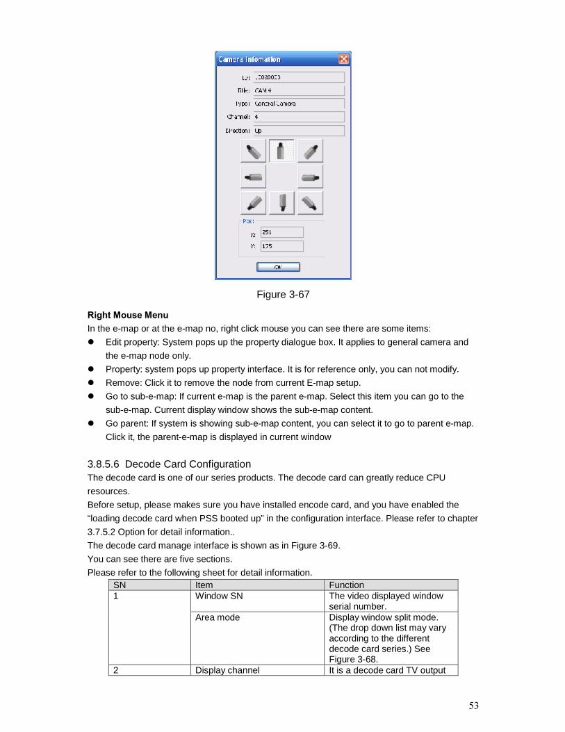
Camera PropertyRight click the camera in the e-map, you can view there are three options: Editproperty/property/remove.Click property button, you can see an interface is shown as in Figure 3-67. ID: Camera ID. Title: Camera description information Type: Camera type. Channel: The channel serial number in the device. Direction: This item is for general camera. It can be modified. IPC, speed dome and alarm
device do not have this item.
53
Figure 3-67
Right Mouse MenuIn the e-map or at the e-map no, right click mouse you can see there are some items: Edit property: System pops up the property dialogue box. It applies to general camera and
the e-map node only. Property: system pops up property interface. It is for reference only, you can not modify. Remove: Click it to remove the node from current E-map setup. Go to sub-e-map: If current e-map is the parent e-map. Select this item you can go to the
sub-e-map. Current display window shows the sub-e-map content. Go parent: If system is showing sub-e-map content, you can select it to go to parent e-map.
Click it, the parent-e-map is displayed in current window
3.8.5.6 Decode Card ConfigurationThe decode card is one of our series products. The decode card can greatly reduce CPUresources.Before setup, please makes sure you have installed encode card, and you have enabled the“loading decode card when PSS booted up” in the configuration interface. Please refer to chapter3.7.5.2 Option for detail information..The decode card manage interface is shown as in Figure 3-69.You can see there are five sections.Please refer to the following sheet for detail information.
SN Item FunctionWindow SN The video displayed window
serial number.1
Area mode Display window split mode.(The drop down list may varyaccording to the differentdecode card series.) SeeFigure 3-68.
2 Display channel It is a decode card TV output

54
serial number.Binding Binding decode card TV
output serial number and PCvideo displayed window.
TV/VGA There are two options. Youcan output to the TV device orVGA device.
3 Output video offset When decode card is output,sometimes the image mayoffset. Please adjust the leftand right limit to locate it in themiddle. The pan value rangesfrom 0 to 800 and the tilevalue ranges from 0 to 600.
4 Decode card bindinginformation list
This interface is for referenceonly.
5 Brightness You can adjust decode cardbright value.
Figure 3-68
ImportantThe limit setup and the brightness setup become active immediately!You need to reboot to view the binding setup.
Figure 3-69
3.8.5.7 User ManagementImportant
① ②
③
⑤
④

55
Only the admin can go to the following interface.User manage interface is shown as below. See Figure 3-70. User information list Here you can view all user information. ID: The account name you log in the PSS. Password: The password you input to log in. Confirm password: Please input password again to verify. Name: User name information or other. Sex: female or male. Information User note information. System path: Here you can specify use configuration save path. Right: You can draw a circle to enable corresponding information.
Figure 3-70
Click OK button, system pops up the following dialogue box, please click yes button to savecurrent information. See Figure 3-71.
Figure 3-71
3.8.5.8 Device ManagerThe device manage interface can be divided into two parts. The device information list part isshown as in Figure 3-72.In the device information list, you can view the added device information.You can select a user to see different devices since various users have different rights. Admincan view all devices.

56
Figure 3-72
Search device: You can click it to view all the devices available. See Figure 3-73.Please noteif the device does not support search function, you can not view it in the list.
Figure 3-73
Import/Export: Export current device information to the xml file or import device xml file tocurrent list.
Device information: When you select one device in the list, you can view and modify thedetailed device information. See Figure 3-74.
Please note, the user name, password in the following figure (Figure 3-74) are for you to login the device. It has no relationship with the PSS. If you have enabled the automatically loginfunction, you need to input the channel amount here.

57
Card SN: It is for mobile DVR only. You need to input the card number if you have enabledthe automatically login function.
Figure 3-74
About DDNS and IP addressIf you enabled DDNS function, the IP address information is invalid. That is to say, Figure 3-75and Figure 3-76 can not be active at the same time.Please note, in Figure 3-75, you can input IP address such as 10.7.5.11 or you can input domainname such as www.yahoo.com.
Figure 3-75
Figure 3-76
3.8.5.9 NVD ManageNVD manage interface is shown as in Figure 3-77.Please refer to chapter 3.8.5.7 for operation information.
58
Figure 3-77
3.8.5.10 SNVD ManageSNVD manage interface is shown as below. See Figure 3-78.Please refer to chapter 3.8.5.10 for operation information.
Figure 3-78
ImportantUser name and password here is for you to login the device. It has no relationship with oursoftware operation!
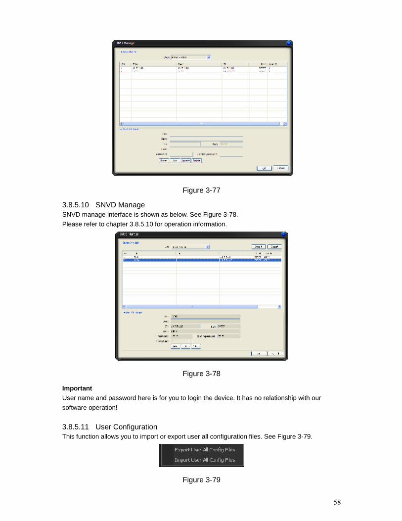
3.8.5.11 User ConfigurationThis function allows you to import or export user all configuration files. See Figure 3-79.
Figure 3-79

59
3.9 Device Health StatusHere you can update device status regularly, view disk health status; decode alarm, record andthe alarm information you most concern.Please go to chapter 3.7.5.2 Option to set the alarm information you most concern. See Figure3-80.
Figure 3-80
Device health status interface is shown as inFigure 3-81. Please refer to the following sheet for detail information.SN Note1 It is device name and its channel number.
In Figure 3-81, you can view the device nameis GBE and it has 16 channels.
2 HDD status. In Figure 3-81, HDD is runningproperly.
3 HDD is full or not. In Figure 3-81, HDD isrunning properly.
4 Decode or encoder alarm.5 Device record status. Green light means
current channel is recording.Please go to chapter 3.7.5.2 Option to setrefresh interval.
6 It is the first alarm item you set in Figure 3-80.So, in Figure 3-81, you can see the externalalarm information. Red light means there is analarm.Please go to chapter 3.7.5.2 Option to setrefresh interval.
7 It is the first alarm item you set in Figure 3-80.So, in Figure 3-81, you can see the externalalarm information. Blue light means there is analarm.Please go to chapter 3.7.5.2 Option to setrefresh interval.
8 Device IP.
Figure 3-81
In Figure 3-81, double click mouse, you can go to alarm record interface. Please refer to chapter3.7.2 Alarm for alarm record interface information.
1 2 3 4
567
8

60
Once there are HDD alarm and encode/decode alarm, the interface is shown as below. SeeFigure 3-82.You can see there is HDD error, HDD is full and the encode/decode alarm.
Figure 3-82
3.10 Full MenuThe full menu interface is shown as below. See Figure 3-83.
Figure 3-83
3.10.1 Modify PasswordPlease refer to chapter 3.7.5.1.
3.10.2 DeviceIt has the following sub-menu. See Figure 3-84. Device management: Please refer to chapter 3.8.5.8. Health report: Please refer to chapter 3.8.4.3. NVD manage: Please refer to chapter 3.8.5.9. NVD control: Please refer to chapter 3.8.4.2. SNVD manage: Please refer to chapter 3.8.5.10.
Figure 3-84
3.10.3 AlarmIt has the following sub-menu. See Figure 3-85. Alarm link (activation) video: Please refer to chapter 3.8.4.5. Alarm record plan: Please refer to chapter 3.8.5.4.
61
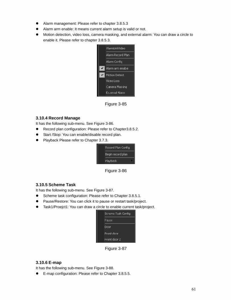
Alarm management: Please refer to chapter 3.8.5.3 Alarm arm enable: It means current alarm setup is valid or not. Motion detection, video loss, camera masking, and external alarm: You can draw a circle to
enable it. Please refer to chapter 3.8.5.3.
Figure 3-85
3.10.4 Record ManageIt has the following sub-menu. See Figure 3-86. Record plan configuration: Please refer to Chapter3.8.5.2. Start /Stop: You can enable/disable record plan. Playback Please refer to Chapter 3.7.3.
Figure 3-86
3.10.5 Scheme TaskIt has the following sub-menu. See Figure 3-87. Scheme task configuration: Please refer to Chapter 3.8.5.1. Pause/Restore: You can click it to pause or restart task/project. Task1/Proejct1: You can draw a circle to enable current task/project.
Figure 3-87
3.10.6 E-mapIt has the following sub-menu. See Figure 3-88. E-map configuration: Please refer to Chapter 3.8.5.5.

62
E-map view: Please refer to Chapter 3.7.4.
Figure 3-88
3.10.7 ConfigurationIt has the following sub-menu. See Figure 3-89. Option: Please refer to Chapter 3.7.5.2. Scheme task configuration: Please refer to Chapter 3.8.5.1. Alarm management: Please refer to Chapter 3.8.5.3. Record plan configuration: Please refer to Chapter 3.8.5.2. E-map configuration: Please refer to Chapter 3.8.5.5. User manage: Please refer to Chapter 3.8.5.7. Device management: Please refer to Chapter 3.8.5.8. NVD management: Please refer to Chapter 3.8.5.9. SNVD management: Please refer to Chapter 3.8.5.10. User configuration: Please refer to Chapter 3.8.5.11.
Figure 3-89
3.10.8 Log QueryPlease refer to chapter 3.8.4.4 for detail information.
3.10.9 Log outClick log out button, system pops up the following dialogue box. See Figure 3-90. Please inputthe proper password to exit PSS application. You can see the system goes back to login interface.You need to input user name and password to login again. Please refer to chapter 3.1.

63
Figure 3-90
3.10.10 ExitClick exit button, system pops up the following dialogue box. See Figure 3-91.Please input proper password and then click OK button to exit PSS.
Figure 3-91
3.11Tray MenuClick tray menu, it is shown as in Figure 3-92.
Figure 3-92
3.11.1 Modify PasswordPlease refer to chapter 3.7.5.1.

64
3.11.2 AlarmIt has the following sub-menu. See Figure 3-93.Please refer to Chapter 3.10.3.
Figure 3-93
3.11.3 E-map ViewPlease refer to chapter 3.7.4.
3.11.4 Color Default SetupPlease refer to chapter 3.8.4.4.
3.11.5 Scheme TaskIt has the following sub-menu. See Figure 3-94.Please refer to chapter 3.10.5.
Figure 3-94
3.11.6 Begin/Stop Record PlanYou can click it to enable/disable current record plan.
3.11.7 Log QueryPlease refer to chapter 3.8.4.4 for detail information.
3.11.8 Close Alarm SoundPlease refer to chapter 3.8.4.5.
3.11.9 Log outPlease refer to chapter 3.10.8.
3.11.10 ExitPlease refer to chapter 3.10.9.
65
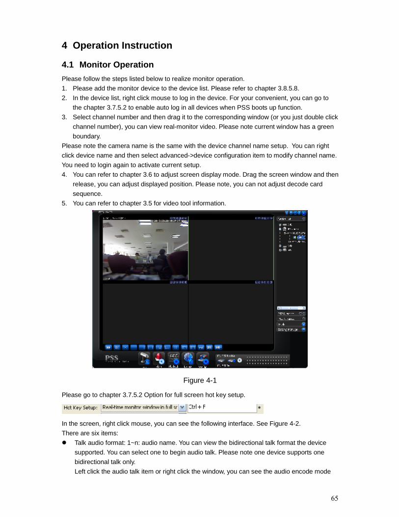
4 Operation Instruction
4.1 Monitor OperationPlease follow the steps listed below to realize monitor operation.1. Please add the monitor device to the device list. Please refer to chapter 3.8.5.8.2. In the device list, right click mouse to log in the device. For your convenient, you can go to
the chapter 3.7.5.2 to enable auto log in all devices when PSS boots up function.3. Select channel number and then drag it to the corresponding window (or you just double click
channel number), you can view real-monitor video. Please note current window has a greenboundary.
Please note the camera name is the same with the device channel name setup. You can rightclick device name and then select advanced->device configuration item to modify channel name.You need to login again to activate current setup.4. You can refer to chapter 3.6 to adjust screen display mode. Drag the screen window and then
release, you can adjust displayed position. Please note, you can not adjust decode cardsequence.
5. You can refer to chapter 3.5 for video tool information.
Figure 4-1
Please go to chapter 3.7.5.2 Option for full screen hot key setup.
In the screen, right click mouse, you can see the following interface. See Figure 4-2.There are six items: Talk audio format: 1~n: audio name. You can view the bidirectional talk format the device
supported. You can select one to begin audio talk. Please note one device supports onebidirectional talk only.Left click the audio talk item or right click the window, you can see the audio encode mode

66
the device supported.Please check the item to enable audio talk function, click it again you can disable currentoperation. Or you can click another item to begin a new operation.
Add current window to the task: You can view task name from the dropdown list. Click it youcan add current window to the Monitor task. If current window is in the task, tthe operationfailed.
Add all windows to the task: You can view the task name from the dropdown list. Click it youcan add all windows to the Monitor task. If current window has been in the task, then theoperation failed.
Copy video information: You can click it to copy current video information. After you click thebutton, you can see "paste video information" button.
Paste video information: Click it you can paste selected video to current window. SNVD output: :( Important: Please make sure you have logged in the SNVD, otherwise you
can not see this item.)You can view the logged in SNVD name: You can go to SNVDmanagement to add the device, and then you can go to the Device list to login the device.SNVD monitor name: Click it, you can open the same video in the SNVD specified monitor.
Video attribute: Click the video attribute button, you can see device name/channeltitle/stream type/video quality/real-time(fluent ) level.
For detailed video control zone information, please refer to chapter 3.5.
Figure 4-2
4.2 Monitor Task and Monitor Project1. Pease refer to chapter 3.8.5.1 to establish task and project.2. Please refer to chapter 3.7.1 to enable monitor task and monitor project.
4.3 PTZ ControlBefore operation, please make sure current channel supports PTZ control.Select step and then use the 8 direction buttons, you can realize PTZ control.You can click the 3D intelligent positioning button to realize 3D intelligent positioning function.Please note, during the whole process, other buttons are all invalid.

67
Click the lock icon , the PTZ interface becomes independent and can overlay the specified
screen as you desire.
You can go to chapter 3.7.5.2 Option for hotkey setup.
For detail operation information, please refer to chapter 3.8.2 and chapter 3.8.3.
Figure 4-3
4.4 Playback4.4.1 Device Record Playback1. Please log in the device you want to search.2. Click playback button3. Select the device name and then select selected channel.4. Select record type: Record/Alarm/Motion detection/card number.5. Set search period or cad number.6. Click search button.7. You can draw a circle to select the corresponding result and then click download button to
download to the local end.8. Select one video window and then double click search result, you can playback the record.
4.4.2 Local Record Playback1. Click playback button.2. Select local record3. Select the device name (if you want to search all devices, you can select unknown.). Then
you can select channel number.4. Select the record type: Record/Alarm/Card number and others.5. Set search period or cad number.6. Click search button.7. In the searched results, click remove button you can delete local record. Select one video
window and then double click search result, you can playback the record.
68
4.4.3 DownloadSelect the file(s) you want to download and then click download button.During the download process, you can click cancel button to terminate current operation.The download files information is automatically added to the local record. You can search fromthe local record.Please note, the download process will pause if current channel is playback device record/ Thedownload resume after playback completes.
4.4.4 Record Play ControlSystem maximally supports 4-ch playback.Please refer to chapter 3.7.3 for playback information.Double click video window you can adjust display mode.You can enable snapshot function during playback.
4.4.5 OthersPlease refer to chapter 3.7.3 for playback information.Record playback can download the specified record to the local end.The download files information is automatically added to the local record. You can search fromthe local record.
4.5 Snapshot and Manual RecordIn real-time monitor or playback mode, you can enable snapshot or manual record function.Please click snapshot to save current image to specified path.You can click manual record button to enable recode function. Click it again, you can stopmanual record.The snapshot file or manual recorded file is automatically added to the local record. You cansearch to playback.
4.6 E-mapPlease go to chapter 3.8.5.5 to establish E-map.Please go to chapter 3.7.4 to view the detail e-map information.E-map window can be displayed independently.Double click the camera name in the E-map; you can enable real-time monitor function in thevideo window.When alarm occurs, corresponding node becomes flashing.
4.7 Log outPlease refer to chapter 3.10.8 or chapter 3.11.9 for log out information.Click log out button, the interface is shown as below. See Figure 4-4. You need to input theproper password and then click OK button to logout the PSS.

69
Figure 4-4
Now you can see system goes back to log in interface. See Figure 4-5. Current operation andconfiguration all stopped. You need to input user name and password to log in. The record plan,task and project, shortcut key, and right information are all for logged in user.
Figure 4-5

70
5 Peripheral Device Operation
5.1 Decode CardThe decode card is one of our series product. The decode card can greatly reduce CPUresources.Before setup, please makes sure you have installed encode card, and you have enabled the“loading decode card when PSS booted up” in the Option interface (chapter 3.7.5.2).The decode card can outputs video to the TV or VGA device. You can just select the videochannel and then drag it to the decode card binding monitor channel.For decode card configuration operation, please refer to chapter 3.8.5.6.
5.2 NVD5.2.1 MenuNVD is a network video decoder. It is one of our series products. It can connect to the videosourcing device. It has TV output and TV video split.You can go to the NVD manage interface from the right tool button. See Figure 5-1.
Figure 5-1
NVD is a network device, you need to add NVD device first and then use it.Please refer to chapter 3.8.5.9 for NVD device managePlease refer to chapter 3.8.4.2 for NVD control operation.
5.2.2 NVD Control PrinciplePlease read the following principles so that you can understand how the PSS control the NVD. PSS logged in NVD and then control NVD. PSS transfer the device information and channel information to the NVD and then NVD can
log in the other devices to enable video. PSS control NVD to enable video and split video NVD can output the video data after split. (The data here can be the input video of the other
device.) NVD has four video outputs and each vide output can integrate video from four channels to
a four-channel video window.

71
Please note you need to log in the NVD if you want to use it.NVD operation consists of three sections: operation, tour and decode tour. All the operationsbecome active when NVD is running normally.On the top left, you can view the added NVD device. On the top button, you can view other videosourcing devices.Remotely control the NVD to open the video and then switch the split mode. The operation is thesame as the general video zone. But the video window only displays current connected device IPand channel serial number, the NVD video is not in the window. See Figure 5-2.
Figure 5-2
If you see the following dialogue box, you can see the NVD has reached the max decodecapacity. See Figure 5-3.
Figure 5-3
Please close the video channel, until you see the following dialogue box. See Figure 5-4.Now the NVD has restored capacity and can run properly.

72
Figure 5-4
ImportantDo not connect the PAL format device and NTSC device to the same NVD!
5.2.3 Audio talkThis function is for G6 special series only.The audio talk is the audio transmission between the video sourcing device and NVD.In the NVD interface, right click mouse to open the channel window. System pops up the audioencoded mode system supported, you can select to enable audio talk mode.Please note if the video sourcing device and NVD has no common audio encode mode, then theaudio talk function can not be enabled.Note: One device supports one audio function only.Tour interface is shown as in below. See Figure 5-5. Search: Search the selected TV output tour setup of current NVD device. Add: Add current tour information to the TV output channel of current device. Delete: Click it to remove the selected tour setup information. Delete all: Click it to remove all tour setups of current TV output channel. Tour: Click it to begin the tour setup. Interval: The operation interval between the tour setups.
Figure 5-5

73
Tour: Remotely control NVD to distribute the video souring to realize remote tour function (TVoutput).Video mode: Now system supports 1/4 window split. Double click one video window, you canswitch video display mode, it can display in the NVD output device immediately. See Figure 5-6.
Figure 5-6
The decode tour interface is shown as in Figure 5-7. NVD device: Here you can view the NVD device you selected from the NVD device tree. Decode channel: Here you can select the decode tour channel of the NVD device. Stay time (s): Here you can select the interval between the decode tour. It is the video stay
time in each channel. Video channel: You can drag the video channel on the left corner to the column here and
then release to set the video channel information. Add: Click it a odd current video channel tour information to the list. Update: Update the list to the latest information. Cancel: Restore the video channel information. Do not save current modification. Delete: Click it to delete the selected item in the list. Delete all: Click it to delete all the items in the list. Save: Save the latest setup information in the remote NVD device. Pause: Pause the decode tour operation of the remote NVD device. Resume: Restore the decode tour operation of the remote NVD device. Stop: Stop the decode tour operation of the remote NVD device. Start: Begin the decode tour operation of the remote NVD device.Please note, the add/delete operation only becomes valid when the NVD connection is OK.

74
Figure 5-7
Note: This user’s manual is for reference only. Slight difference may be found in the user
interface. All the designs and software here are subject to change without prior written notice. Please visit our website for more information.