professional solar mounting systems open area...
TRANSCRIPT

Professional solar mounting systemsOpen area systems

2
The Schletter Open area system has been designed in order to provide an economic and convenient mounting solution that allows open area plants in always any landscape situation.
In many cases, Schletter could con-siderably reduce the overall cost for large photovoltaic plants by using pile-driven metal foundations. These metal supports that are pile-driven into the ground make the utilization of concrete foundations redundant and thus save both work and material cost.
The measurements and the design of the system depend on the exact and detailed analysis of every specifi c area, including a soil analysis and pressure tests and also on the wind and snow loads onto the specifi c area. Thus, we are able to install photovoltaic plants with verifi ed long-term structural safety at fair prices!
Alternatively, the PvMax3 system al-lows open area mounting onto concrete foundations in cases in which the FS system is not economic due to the size of the plant or is not feasible because of the soil structure. The PvMax3 system (page 14) is mainly used for plant sizes up to about 100 kW. For big plants start-ing from about 100 kW, we recommend the utilization of pile-driven foundations.
State-of-the-art production proce-dures grant effi cient manufacturing of standard components as well as quick and fl exible realization of special constructions on customers' request. The quality of our products is supervised according to DIN ISO 9001:2008. Being a founding member of RAL-Solar, we campaign for the further development of quality standards and for professional seperation of the areas of competence and responsibility.
FS systems - innovations ...that´s the way to build big solar plants...that´s the way to build big solar plants

3
FS systems - innovations ...that´s the way to build big solar plants
Project procedure From planning to completion
Check list
In order to be able to prepare the planning of an open area plant in an optimum manner, we offer our custom-ers project-specifi c check lists that can be downloaded at www.schletter.eu. This fi rst step is decisive for the further procedure and enables us to work out an individual offer for your location and your plant parameters.
Digitalized check lists for all systems are available for download in 8 lan-guages on our website.
Project procedure
1) Complete the project check list and send it back to us2) Creation of a guiding price offer
3) Geological analysis and creation of the soil survey4) Planning and offer of the most economic rack size5) Final offer and scheduling of the mounting operations6) Customized production of the system components7) Material delivery of the complete system to the installation site8) Mounting of the plant up to the level of completetion that was agreed before
1-3 days
2-3 weeks
4-6 weeks
Individual

4
Your advantages
• No soil sealing • High durability due to ideal material combinations• Extremely short mounting time• Considerably reduced effort for planning and mounting due to the use of GPS technology• Unapproachably fast and effi cient with large plants• Fewer screws• Maximum level of pre-fabrication• Optimized material utilization• Perfectly synchronized system components• Optimum setting options• Optimum accessibility for site maintenance (central support)• Filed for patent at the European Patent Offi ce
• 10-year durability warranty*
*Further information and warranty conditions at www.schletter.eu
Open area mounting system FS
The FS system has been optimized in order to allow for a fast and economic realization of large photovoltaic plants with any desired kind of photovoltaic module. Pile-driven steel profi les with optimized geometry are the foundation of all systems of this design series and gurarantee long-term durability, opti-mum anchoring in the soil, minimum soil sealing and good accessibility for later maintenance operations on the installation site. The module bearing construction is made up of aluminum and is pre-fabricated to 100%, it can be delivered to the installation site just in time in any desired quantity. Unfold it − put it on − screw it − that´s it.The mounting of the foundation, of the load-bearing structure and also the mounting of the modules can be inte-grated in the offer on customer request. A complete machinery park with more than 20 hydraulic pile-drivers and our experienced staff make short mounting times possilble, even with large projects.
Examples for mounting variants
With a total capacity of more than 2GW, the open area mounting system FS is the fi gure-head of our Schletter open area systems.Projects like Brandis (40MW), Lieberose (53MW) or San Alberto & Alfonsine (70MW) show that an unobjectionably verifi ed structural safety, high-value materials and economic prices are no confl icting targets!
FS systemGeneration 6
FS2V
FS3H FS4H
FS5H FS6H
With a total capacity of more
fi gure-head of our Schletter
Projects like Brandis (40MW),
Alberto & Alfonsine (70MW) show that an unobjectionably verifi ed structural safety, high-value materials and economic prices
Generation 6
2 vertical modules
3 horizontal modules
5 horizontal modules
4 horizontal modules
6 horizontal modules

5
Your advantages
The stable and price-worthy system on the basis of the well-proven FS open area system Gen5 stands for.
• Additional yields due to seasonal optimization of the module angle• Perfectly synchronized system components• Optimum accessibility for terrain maintenance (central support)• No soil sealing• High durability due to ideal material combinations• Extremely short mounting time
• 10-year durability warranty*
*Further information and warranty conditions at www.schletter.eu
Adjustable system FSVario
The FSVario system is the logical further development of the FS open area system series. Especially if there is a regular staff on the site, continuous optimization of the module angle is a welcome possibility to gain consider-ably higher yields.
The minimization of mechnical inter-faces and the purposeful abdication of automatic control systems results in a very price-effi cient construction made of high-value materials and also very short mounting times. Due to the adaption of FSVario to Gen5, now the same confi guration of the racks like for the usual FS system can be used. This means considerably more power per rack (for example FS2V-Vario).
Adjustable system FSVarioAdjustable system FSVario

6
o
o
o
–
Steel girder in main bearing direction, e.g. IPE
Bending stiffness x-direction (maindirection of loading in installation position)
Effective contact surface for soil fricition (determines the maximum tensile force in the soil and the most economic rack size)
The effective counterforce of the soilanchoring determines the maximum admissible moment of load and thus the most economic rack size
Uninterrupted profi le without interface No corrosive action, no interfaces close to the ground
Steel girder90° in main bearing direction, e.g. IPE
Bending stiffness x-direction (maindirection of loading in installation position)
Effective contact surface for soil friciton (determines the maximum tensile force in the soil and thus the most economic rack size)
The effective counterforce of the soilanchoring determines the maximum admissible moment of load and thus the most economic rack size
Uninterrupted profi le without interface No corrosive action, no interfaces close to the ground
Round tube (for example screw foundation)
Bending stiffness x-direction (maindirection of loading in installation position)
Only the outer side is relevant regard-ing soil friction; Thus, the material is only partially economically utilized! In comparison to pile-driven founda-tions, threads on the foundation only negibly increase the soil area that is important and effective for the tensile strength.
(The counterforce is limited by the wedge effect)
Interfaces (welding seams, contactpoints, different material combinations are potential weak spots at the critical spot above the ground (vegetation, dampness, etc.)
–
+
+
++
Important characteristics Comparison of different pile driven profi les
+
+
–
++
Effective soil anchoring in load direction Effective contact surface for soil friction

7
Load-bearing profi le, roll-formed Developed by the Schletter GmbH
High bending stiffness,economic material utilization.
Regarding soil friction, both inner and outer side are relevant optimum soil anchoring means economic material utilization
Reliable soil anchoring even in case of problematic soil compositions
Avoidance of interfaces (welding joints, contact points, different mate-rial combinations)
++
++
++
++
Summary
The choice of the right foundation profi le shape is decisive for a safe and at the same time economic soil anchoring respectively foun-dation of the plant.
A technical comparison of the advantages and disadvantages shows: The trapezoidal profi le shape combines most technical advantages and optimum material utilization.

8
Extruded aluminum profi le
Corrosion resistance
Material utilization, costs
Stable value
Constructional optimization of the mounting characteristics due tocustomized shaping
Optimum structural characteristics due to a closed cross section
Optimum structural characteristics due to a optimization of the material distribution
Optimum structural characteristics by adaption of the profi le shape to the setting angle
Rolled steel profi le, thick-wall
Corrosion-resistant, because hot dip galvanizing is possible
Material utilization, costs
Scrap value >0
Only certain shapings are possible
Open cross sections
Only one wall thickness is possible
In most cases, there are only rectangular cross sections
Rolled steel profi le, thin-wall
Prone to corrosion (Hot dip galvaniz-ing of thin metal sheets is not pos-sible, the cutting edges are bare)
Material utilization, costs
Scrap value >0
Only certain shapings are possible
Open cross sections
Only one wall thickness is possible
In most cases, there are only rectangular cross sections
The characteristics of the module bearing profi le decisively determine the economic effi ciency of the complete load-bearing system. Optimum material utilization and optimum adaption of the profi le shape to the application case are especially important!
++
o
++
++
++
++
++
–
+
o
o
o
–
–
+
–
o
o
o
–
–
Important characteristics Comparison of load-bearing profi le shapes

9
Hydraulic pile driversSimple and effi cient
Your advantages
• Economically priced• Structural safety verifi able by 100%• Quick and effi cient for large plants• Optimum accessibility for site maintenance• No interfaces close to the ground• Effi cient corrosion protection• No painstaking screwing close to the ground• No complicated fl ange components
Foundation
Generally, the foundation procedure determines the maximum mounting speed – especially with diffi cult soil conditions. Hot-dip galvanized pile- driven profi les in different size cat-egories are used for the foundation. The specially developed kind of pile driving grants an optimum anchor-ing in the soil and maximum bending stiffness at the same time. Thus, the anchoring forces can also be transmitted up to the upper connec-tion point, so that the plant will have optimum structural safety against wind and snow loads.
Pile driving technology with disperser equipping
Pile-driving with disperser-equipping opens up a new dimension in the eco-nomically optimized mounting of large open area plants!
Special pile-driving procedure
The anchoring of the pile driven profi les in the soil is carried out using special terrain-friendly hydraulic pile drivers. This pile-driving technique is especially suitable for very big plants. Depending on the terrain, a pile-driving performance of 250 piles/day can be achieved. Pile-driving on diffi cult terrain (stones, etc.) is also possible. In case of rocky subsoils, the machine can be additionally equipped with a drilling unit. Mounting on slopes is also pos-sible.
Important characteristics Comparison of load-bearing profi le shapes
GPS pile driving - GPS-aided surveying, software-aided planning, driverless pile-driving systems including software-aided planning of lightning protection systems
A completely integrated soft-ware-aided concept of site measuring up to a driverless machine operation with straight to the point positioning allows for further advantages regarding work speed and prices. Lightning protection programs complete the range of services.

10
System characteristics
For elevations in open areas with metal foundations (pile-driven piles), it is indis-pensable to carry out geological surveys to determine the accordant pile forces. The geological survey is the basis for the creation of the structural analysis of the foundation. In order to get the most exact picture of the situation on location, the following surveys are carried out by our specialists:
• Inclined pull tests in the effective load direction• Horizontal pressure tests• Creation of soil profi les• Chemical analysis in a laboratory
Evaluation
The results of these examinations are compiled in a comprehensive report (German, English, Italian, French, or Spanish) and evaluated in a structural analysis (determination of the anchor-ing depth). A geological survey only gives an impression of the soil on the installation site. An evaluation can only be carried out by a specialized soil structural engineer. In order to get a testable evaluation, this structural engi-neer must be entitled to offi cially submit documents.
FS systemGeological analysis
Mechanical background of inclined pulling
The basic idea of horizontal pull tests is the fact that the wind does not act in an isolated manner in vertical or horizontal direction, but almost perpendicular to the modulde surface. Thus, a surface pressure is created from the transmission of the bending moment in the form of a pair of forces. In case of inclinations of more than 15°, the frictional resistance between the pile and the surrounding ground is usually higher than the jacket friction, which leads to a higher pull-out resistance.

11
Cross beams
The cross beam always has a profi le geometry that is aligned to the fl ow of forces (Schletter protection of utility models). Thus, the required structural features are achieved with minimum material utilization. Accordant fi xation grooves are integrated in all profi les in order to make simple mounting pos-sible. The cross beams are fastened to the supporting units by means of special mounting claws.
Module clamps
For any kind of module, especially for the very damageable thin-fi lm modules, suitable clamps are available. In order to optimize the clamping geometry, we cooperate with the producers of thin-fi lm modules and also carry out structural FEM-simulations.
Ideal surface utilization
Module mounting is carried out quickly and cost-savingly – according to the desired module laying either from the ground or with respective aid devices. Framed modules are usually mounted vertically above each other, unframed thin-fi lm modules usually are mounted horizontally above each other, because like this the structural characteristics of the can be used in an optimum manner.
Comprehensive structural calcula-tions according to the standards
A standard for "roofs of station plat-forms" with a maximum inclination of 10° simply is not applicable for pho-tovoltaic plants with an inclination of 30°. This structural analysis based on an inapplicable standard may require only a lower material effort, but it will be irrelevant in case of emergency and does not safeguard the contin-ued existence of the plant!
FS systemThe universal unit assembly system

12
Lightning protection
On request, the complete plant can be equipped with an exterior lightning pro-tection by adding just a few additional components. For this purpose, the Schletter GmbH offers you a special planning program.
Cable guiding
For an optimized cable guiding, we can offer you the following accessories:
• Cable duct• Cable clip for purlin• Cable clip for girder• Pipe clamp for foundation• Cable tray for AC cabling
SecuFix / SecuFix2
Schletter SecuFix is an extended anti-theft device for your valuable modules!
• Can be upgraded anytime• Almost unbreakable• Unrivalled value for money
For ordinary socket head or Torx screws, we will deliver a quality steel ball with the exact diameter as an accessory on request. After the put-ting into operation of the plant, simply secure all screws by driving in the SecuFix ball − that´s it!
SecuFix2 is an ideal completion of Se-cuFix and an additional safety device to make the removal of modules really diffi -cult. For this purpose, the fi rst module of a row is fi xed from below using a special additional kit. Thus, we can provide ex-tra protection for your photovoltaic plant!
Individual extensions Optional accessories
Cable clip for purlin
Cable duct
Lightning protection
Cable clip for girder
Pipe clamp for foundation
Cable tray for AC cabling
SecuFix

13
OptiBond gluing technology
Your advantages
• Structurally optimized for big module surfaces• Minimum mounting time• with anti-theft device
• 10-year durability warranty*
*Further information and warranty conditions at www.schletter.eu
Due to the cost pressure caused by the annual decrease of the compensation for electricity fed into the grid, there is a tendency towards thin-fi lm modules especially with big plants in open areas. Thus, the aim of many module produc-ers are often very big-surfaced modules in double glass-design, as they are likely to bring about a cost reduction both in the process of production and in the photovoltaic plant itself.
An increase of the bearing capacity and thereby an enlargement of the module measurements is only possible by suit-able fi xations within the module area. The Schletter GmbH has developed an appropriate glue procedure with numer-ous module manufacturers to connect also these big surface modules me-chanically optimal to the substructure.
OptiBond product sheet OptiBond mounting movie (in the solar area on our website www.schletter.eu)
able fi xations within the module area. The Schletter GmbH has developed an appropriate glue procedure with numer-ous module manufacturers to connect also these big surface modules me-chanically optimal to the substructure.
(in the solar area on our website www.schletter.eu)
OptiBond gluing technology
14
Your advantages
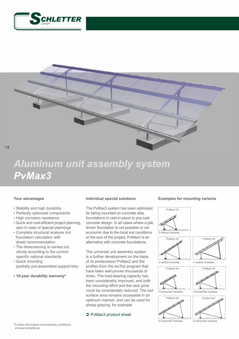
• Stability and high durability• Perfectly optimized components• High corrosion resistance • Quick and cost-effi cient project planning, also in case of special plannings• Complete structural analysis incl. foundation calculation with dowel recommendation• The dimensioning is carried out strictly according to the current specifi c national standards• Quick mounting (partially pre-assembled support kits)
• 10-year durability warranty*
*Further information and warranty conditions at www.schletter.eu
Individual special solutions
The PvMax3 system has been optimized for being mounted on concrete strip foundations in cast-in-place or pre-cast concrete design. In all cases where a pile driven foundation is not possible or not economic due to the local soil conditions or the size of the project, PvMax3 is an alternative with concrete foundations.
The universal unit assembly system is a further development on the basis of its predecessor PvMax2 and the profi les from the IsoTop program that have been well-proven thousands of times. The load-bearing capacity has been considerably improved, and both the mounting effort and the rack price could be considerably reduced. The soil surface area remains accessible in an optimum manner, and can be used for sheep grazing, for example.
PvMax3 product sheet
Examples for mounting variants
Aluminum unit assembly system PvMax3
PvMax3 3H PvMax3 4H
PvMax3 5H PvMax3 6H
PvMax3 2V
PvMax3 3V PvMax3 4V
14
2 vertical modules
3 vertical modules
3 horizontal modules
5 horizontal modules
4 vertical modules
4 horizontal modules
6 horizontal modules

15
Your advantages
The well-proven modular system for open areas with optimized superim-posed loads!
• Minimum loading is suffi cient due to a multi-row construction• Especially designed for application on landfi ll sites• Well-proven unit assembly compo- nents based on PvMax2 / PvMax3• Reduced soil pressings by minimized foundation weights
• 10-year durability warranty*
*Further information and warranty conditions at www.schletter.eu
Optimum structural safety
Especially on waste disposal sites, it is mostly not possible to use grounding piles because there is a foil sealing that would be perforated by driven piles. The systems with the PvCombi design are especially optimized for these ap-plication cases by interconnecting the rows (see picture at the top). Due to the enlarged base contact area and the smaller moment of tilt resulting from this, the structural safety of the plant can be reached with less weight loads.
PvCombi product sheet
Unit assembly system PvCombi
15

16
FsIn The inlay system by Schletter
Mounting without clamps
The FsIn system has been designed especially for modules with an addition-al certifi cation for "inlay mounting". In comparison to conventional mounting, this makes a more price-effi cient rack dimensioning and also shorter mount-ing times possible. Thus, an improved overall economic effi ciency of the plants is achieved.
• 10-year durability warranty*
*Further information and warranty conditions at www.schletter.eu
Information
Crystalline modules without additonal certifi ca-tion usually are installed on two horizontal purlins, both on roofs and in open areas, thus it is safeguarded that the module is mounted to the substructure correctly, as tested and certifi ed in the certifi cation procedure according to IEC 61215.
Modules with a special frame dimensioning can be alternatively mounted in inlay systems, as far as there is a special certifi cation. But with these systems, the module frame has to be designed for bigger loads, as the unsup-ported span is much bigger if the modules are mounted vertically.

17
Material
Fastening elements, bolts: Quality steel 1.4301; Profi les: Aluminium MgSi05 /EN AW 6063, EN AW 6005Pile driven foundations: Steel S380, hot-dip galvanized• High life-expectancy, high residual value, no disposal costs• Simple plant repowering due to modular design
Logistics
• Quick and simple mounting• Maximum level of pre-fabrication• Optimized transport to the construction site
Construction
• Adjustment options to equalize ground unevennesses• Cost-optimized overall construction on the basis of structural optimization• For framed and unframed modules
Site maintenance
• Optimum terrain maintenance due to central support• Sheep grazing
Structural calculation
• Individual structural analysis of the site on the basis of a soil survey (for pile driven design)• Individual structural analysis of the system on the basis of regional load values • Load assumptions according to DIN 1055 Part 4 (03/2006), part 5 (06/2005), part 100 (03/2001), Eurocode 1 (06/2002), DIN 4113, DIN 18800, Eurocode 9 and others, respec- tively the accordant specifi c national standards• Patented profi le geometries with optimum material utilization• Verifi cation of all construction components based on FEM-calculation• Vibration simulation of wind loads, optional• Earth quake simulation, optional
Accessories
• Lightning protection system (FSProtect system)• Cable channels, cable ducts• Anti-theft device (SecuFix / SecuFix2) • Components for internal potential equalization • Clamps for different types of modules• Fastening systems for big-surface laminated modules (OptiBond system)
Delivery and services
• Soil survey and soil structural analysis• Individual structural analysis of the site on the basis of regional data• Pile-driving of the foundations and delivery of the complete mounting material• Starting from 100kWp, free of transportation charges on the European mainland• Creation of all rack drawings• Optional: Rack mounting• Optional: Complete module mounting
Lightning protection, earthing, potential equalization
• Extension with exterior lightning protection systems is possible • Components for internal potential equalization certifi ed according to VDE 0100, part 712
Warranty and Certifi cations
• 10-year durability warranty on all Schletter solar mounting systems• Optional: Extension of the durability warranty to 20-25 years - on the basis of a maintenance contract
Technical data Open area systems

18
FS 5HProject: HolzgünzModule type: 1200 x 600Plant size: 4.7 MWpCustomer: JUWI
FS 2VProject: Sierra de YeguasModule type: 1600 x 980Plant size: 2.2 MWpCustomer: ESA
Reference examples Open area systems
FS 5HProject: EhekirchenModule type: 1200 x 600Plant size: 1.2 MWpCustomer: JUWI
FS 3HProject: Antolin & GuadalinModule type: 1673 x 983Plant size: 11.2 MWpCustomer: Systaic

19
FS 2VProject: BoveraModule type: 1650 x 992Plant size: 1.1 MWpCustomer: Wirsol
FS 2VProject: LobosilloModule type: 1650 x 990Plant size: 2.6 MWpCustomer: Ecostream
FS 5HProject: El CuraModule type: 1200 x 600Plant size: 2 MWpCustomer: JUWI
FS 2VProject: AlfonsineModule type: 1650 x 992Plant size: 36 MWpCustomer: TRE Tozzi
Total power
together with
San Alberto:
70MW!
With a delivery quantity of components for solar plants of about 5MW/day, the Schletter GmbH is your partner with experience in safe and cost-effi cient system dimensioning!

20
Reference examples Open area systems
FS 2VProject: LobosilloModule type: Top Solar/YingliPlant size: 14 MWpCustomer: Ecostream
FS 1V – special design VarioProject: Muga IIModule type: 1667 x 1000Plant size: 5 MWpCustomer: Alfa
FS 5HProject: EckendorfModule type: 1200 x 600Plant size: 1.62 MWpCustomer: Solarpark Eckendorf
FS 5HProject: LieberoseModule type: 1200 x 600Plant size: 53 MWpCustomer: JUWI

21
FS 2VProject: RotthalmünsterModule type: 1580 x 808Plant size: 1.5 MWpCustomer: EEPro
FS 5HProject: Rote JahneModule type: 1200 x 600Plant size: 6 MWpCustomer: JUWI
FS 5HProject: BrandisModule type: 1200 x 600Plant size: 40 MWpCustomer: JUWI
FS 3HProject: MenorcaModule type: 1680 x 990Plant size: 3.2 MWpCustomer: SunEnergy

22
„We don´t get any discount for wind and snow loads"(Dr. Cedrik Zapfe; structural engineer with Schletter)
Necessary cost reductions (in view of the cutting of the compensation for electricity fed into the grid) are achieved by optimi-zed mounting. Especially for photovoltaic plants in open areas, the mounting structures are completely pre-assembled in our factory and delivered and installed "just in time" according to an exact delivery schedule.
Comprehensive structural calcula-tions according to the standards
Some of our competitors often do not apply satisfactory structural standards for the structural analysis and the veri-fi cation of structural safety of mounting systems. So, a technical standard for "station platform roofs with an inclina-tion of max. 10 degrees" is just not applicable for photovoltaic plants with an inclination of 30 degrees.
This structural analysis may require only a lower material effort, but it will be irrelevant in case of emergency and does not safeguard the continued existence of the plant!
Statistics of refi ttings - especially with open area plants
Experiences gained in the last years show that mounting structures are per-manently reinforced and re-fi tted due to further technical developments. The fact that ever stronger dimensionings, re-fi ttings and bracings are added in each new generation of product series by some of our competitors show that maybe insuffi cient load assumptions were used when the fi rst generation was designed.
This raises several questions:
• Who has to pay for these refi ttings?• Who can compensate the (non-material) loss of trust of the end customer?• If there is a recall, will all products be completely re-fi tted or will only the most urgent problems be taken care of?• Has the risk to the enormous overall plant value been underestimated just for the sake of a cost reduction on a scale of a few percent?
The fi rst open area systems by Schlet-ter were already installed in 2005. Ever since, there have been no refi tting ac-tions due to insuffi cient system dimen-sioning. Thus, you can confi de in our long-term experience!
Our service Pre-assembly in our factory

23
Anemograph
Time
Win
d ve
loci
ty
Material supervision and component analyses Safety based on certifi ed quality
Vibrations and resonance
Especially one-support open area sys-tems are prone to vibrations. Vibrations that are too strong can lead to material fatigue and failure. Thus, we do not only carry out structural, but also dy-namic calculations for our systems. The vibration frequency is determined and compared to the excitation frequency. By a suffi cient stiffness and a vibration frequency of about 10Hz, a suffi cient distance to the wind excitation frequen-cy (about 0.5Hz) is achieved. Thus, no resonance effect can occur, vibrations are minimized.
Comparison of aluminum and steel girders
The prices of aluminum and steel fl oat independently of each other and will al-ways shift the cost comparison in one or the other direction. Generally, aluminum is of higher value (no corrosion, stable value, etc.), but it can be a bit more expensive.
Structures made of hot-dip-galvanized steel are of comparable high value, but almost as expensive as aluminum in most cases. For hot-dip galvanizing, the steel profi les must have a minimum wall thick-ness, because otherwise they will deform in the hot-dip galvanizing process.Thus, structures are often built using thin, rolled profi les. Those are only electrolytically galvanized (limited dura-bilitiy in the exterior area) and some-times even only strip-galvanized (thus, they have bare cutting edges)!
FEM simulation
Vibration analysis of the module rack

© S
chle
tter G
mbH
, 201
1, I4
0014
9GB
, V1
How to contact us
Order processingPhone: +49 8072 9191 – 205Fax: +49 8072 9191 – 9205E-mail: [email protected]
Logistics servicePhone: +49 8072 9191 – 206Fax: +49 8072 9191 – 9206E-mail: [email protected]
Training informationPhone: +49 8072 9191 – 209Fax: +49 8072 9191 – 9209E-mail: [email protected]
Sales and distributionPhone: +49 8072 9191 – 480Fax: +49 8072 9191 – 9480E-mail: [email protected]
Technical advice and inquiriesPhone: +49 8072 9191 – 201Fax: +49 8072 9191 – 9201E-mail: [email protected]
For a comprehensive and competent consulting in the planning of your plant and for questions concerning logistics and order processing, our members of staff are available from Monday to Friday from 7 am to 5 pm.
Schletter GmbHAlustraße 183527 Kirchdorf/Haag in OB, GERMANY
www.schletter.eu