professional screw technology - wielandinc.com · wk 4 tkg... dist din rail terminal blocks with...
TRANSCRIPT

selos
selos
selos
DIN Rail Terminal Blockswith Screw Connection
Professional Screw Technology
Headquarters:
Wieland Electric GmbH
Brennerstraße 10 - 14
96052 Bamberg, Germany
Sales and Marketing Center:
Wieland Electric GmbH
Benzstraße 9
96052 Bamberg, Germany
Phone +49 (0951) 9324-0
Fax +49 (0951) 9324-198
www.wieland-electric.com
www.gesis.com
Industrial technology Solutions for the control cabinet • DIN rail terminal blocks – Screw, tension spring or push-in connection technology – Wire cross sections up to 240 mm2
– Numerous special functions – Software solutions interfacing to CAE systems • Safety – Safe signal acquisition – Safety switching devices – Modular safety modules – Compact safety controllers – Applicative consultancy and training • Network engineering and fi eldbus systems – Remote maintenance via VPN industrial router and VPN service portal – Industrial Ethernet switches – PLC and I/O systems, standard and increased
environmental conditions • Interface – Power supply units – Overvoltage protection – Coupling relays, semiconductor switches – Timer relays, measuring and monitoring relays – Analog coupling and converter modules – Passive interfaces
Solutions for fi eld applications • Decentralized installation and automation technology – Electrical installation for wind tower – Fieldbus interfaces and motor starters • Connectors for industrial applications – Rectangular and round connectors – Aluminum or plastic housings – Degree of protection up to IP 68 – Current-carrying capacity up to 100 A – Connectors for hazardous areas – Modular, application-specifi c technology
PC board terminals and connectors – Screw or spring clamp connection technology – Spacings: 3.5 mm to 10.16 mm – Refl ow or wave soldering process
Building and installation technology • Building installation systems – Main power supply connectors IP 20/IP 65 ... IP 68 – Bus connectors – Low-voltage connectors – Power distribution system with fl at cables – Distribution systems – Bus systems in KNX, LON and radio technology – DIN rail terminal blocks for electrical installations – Overvoltage protection
0125.0 B 04/12

22
automation
building
electronics
One company group,
a thousand opportunities
The philosophy of the Wieland Group with its headquarters in Bamberg can be summarized that simply. The independent subsidiaries, Wieland Electric and STOCKO Contact, are active beneath Wieland Holding.
Together they cover an extraordinarily wide product portfolio in the field of electrical engineering and electronics. It comprises control cabinet engineering, industrial multipole connectors as well as overvoltage technology and building system technology.
Wieland Electric is active in most areas of automation technology and delivers as the industry’s driver for innovation. Safety first – Wieland Electric is ideally positioned with its modular system solutions such as
With its staff of almost 2,200 employees,
the Wieland Group is at home on all continents.
Subsidiaries in Great Britain, France, Spain,
Italy, Poland, Canada, the USA, China and
Denmark speak for themselves. With a great
number of representatives, Wieland Holding
is active in almost all strategically important
countries. Just a medium-size global player
with a clear commitment to the German
location where most of the products are still
manufactured.
ACTIVE WORLDWIDE
G Photo of the Bamberg
headquarters
G Sales and
Marketing Center
in Bamberg
G STOCKO headquarters in
Wuppertal

33
Series 4000, samos®, samos®PRO and the new sensor PRO safety sensors.
podis®, the solution-oriented system for remote power distribution, and ricos TP, the latest development in the field of automation systems for heavy duty industrial requirements, are only two examples.
In the building installation system sector, Wieland Electric, with its gesis® system, is the world market leader in pluggable electrical installation. With good reason do planners and architects of the tallest and most interesting construction projects worldwide, such as the Petronas Towers in Kuala Lumpur, rely on gesis® components from Wieland. Wieland is the pioneer ona path toward the intelligent home by consistently developing its
gesis® product range, especially with regards to the demands of electronic networking.
Wieland Electric was founded in 1910 in Bamberg. With 800 staff members it is the largest subsidiary within the company group of Wieland Holding. With its numerous innovations, Wieland Electric has become a major supplier of electrical connection technology. Export share is currently at 58 %.
STOCKO Contact is located in North Rhine-Westphalia’s Wuppertal and has been a member of the Wieland Group since 2001. The company can look back at a history of more than 100 years. STOCKO Contact is one of the biggest European manufacturers of connector systems and crimp contacts.
100 years young and
full of innovative energy ...
this is the foundation of our company philosophy.From this statement Wieland Electric will not just maintain, but expand its social responsibility into the future. Eco-friendly high-tech products, manufactured according to state-of-the-art production standards, an audited environmental management system and extensive investments in our facilities with cutting-edge environmental technologies are a matter of fact. A company policy that also commits us to the long term responsibility for the future of our families and children, as well as for the city of Bamberg, in addition to innovative system solutions for our customers. In our opinion, worldwide action and regional responsibility are united.
contacts are green
4
selos
WK 4 E/U WK 4 E/rot
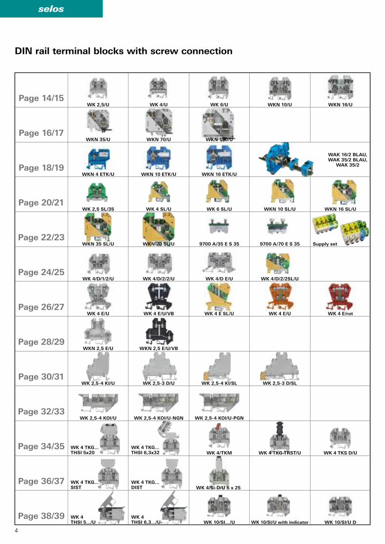
WK 2,5/U WK 4/U WK 6/U WKN 10/U WKN 16/U
WKN 35/U WKN 70/U WKN 150/U
WKN 4 ETK/U WKN 10 ETK/U WKN 16 ETK/U
WAK 16/2 BLAU, WAK 35/2 BLAU,
WAK 35/2
WK 2,5 SL/35 WK 4 SL/U WK 6 SL/U WKN 10 SL/U WKN 16 SL/U
WKN 35 SL/U WKN 70 SL/U 9700 A/35 E S 35 9700 A/70 E S 35
WK 4/D/1/2/U WK 4/D/2/2/U WK 4/D E/U WK 4/D/2/2SL/U
WK 4 E/U WK 4 E/U/VB WK 4 E SL/U
WKN 2,5 E/U WKN 2,5 E/U/VB
WK 2,5-4 KI/U WK 2,5-3 D/U WK 2,5-4 KI/SL WK 2,5-3 D/SL
WK 2,5-4 KOI/U WK 2,5-4 KOI/U-NGN WK 2,5-4 KOI/U-PGN
WK 4 TKG...THSI 5x20
WK 4 TKG...THSI 6,3x32 WK 4/TKM WK 4 TKG-TRST/U WK 4 TKS D/U
WK 4 THSI 5.../U
WK 4 THSI 6,3.../U WK 10/SI…/U WK 10/SI/U D
WK 4/Si-D/U 5 x 25
WK 4 TKG...SIST
WK 4 TKG... DIST
DIN rail terminal blocks with screw connection
Page 14/15
Page 16/17
Page 18/19
Page 32/33
Page 20/21
Page 22/23
Page 24/25
Page 26/27
Page 28/29
Page 30/31
Page 34/35
Page 36/37
Page 38/39
Supply set
WK 10/SI/U with indicator
5
selos
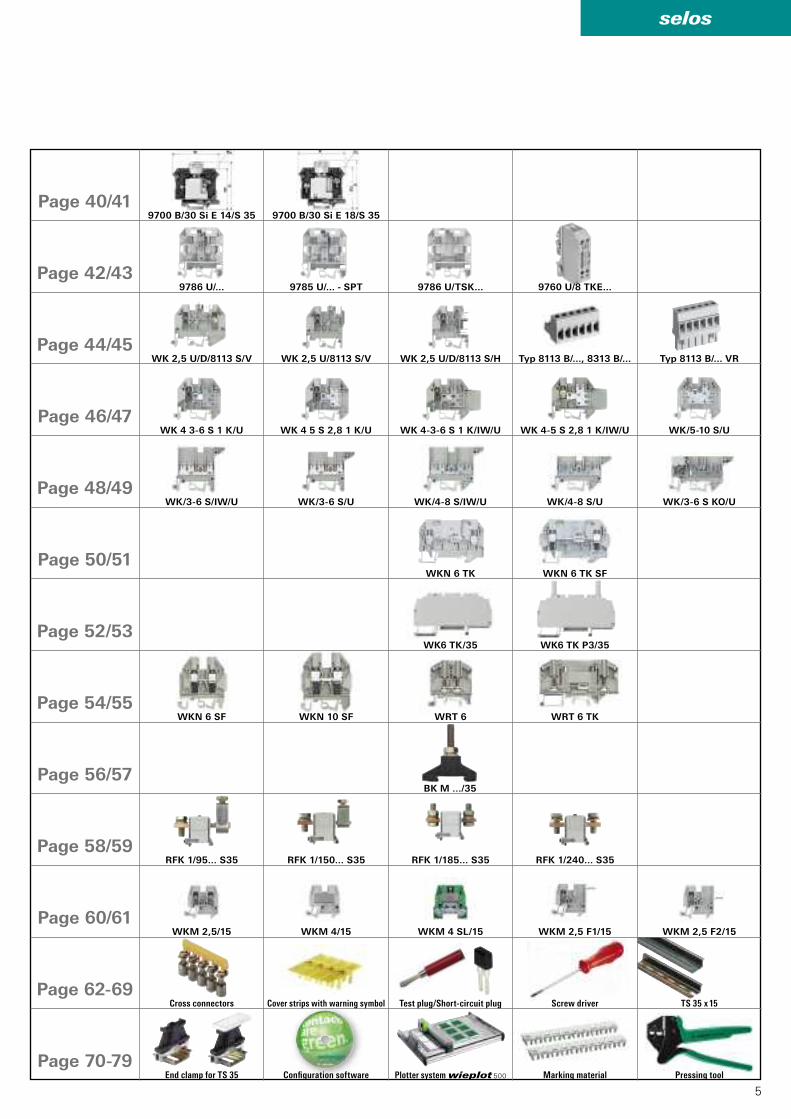
9700 B/30 Si E 18/S 359700 B/30 Si E 14/S 35
9786 U/... 9785 U/... - SPT 9786 U/TSK... 9760 U/8 TKE...
WK 2,5 U/D/8113 S/V WK 2,5 U/8113 S/V WK 2,5 U/D/8113 S/H Typ 8113 B/..., 8313 B/... Typ 8113 B/... VR
WK 4 3-6 S 1 K/U WK 4 5 S 2,8 1 K/U WK 4-3-6 S 1 K/IW/U WK 4-5 S 2,8 1 K/IW/U WK/5-10 S/U
WK/3-6 S/IW/U
WKN 6 SF WKN 10 SF WRT 6 WRT 6 TK
WK/3-6 S/U WK/4-8 S/IW/U WK/4-8 S/U WK/3-6 S KO/U
WKN 6 TK WKN 6 TK SF
WK6 TK/35 WK6 TK P3/35
BK M .../35
RFK 1/95... S35 RFK 1/150... S35 RFK 1/240... S35RFK 1/185... S35
WKM 2,5 F1/15 WKM 2,5 F2/15WKM 2,5/15 WKM 4/15 WKM 4 SL/15
Page 40/41
Page 42/43
Page 44/45
Page 46/47
Page 48/49
Page 60/61
Page 50/51
Page 52/53
Page 54/55
Page 56/57
Page 58/59
Page 62-69
Page 70-79
Cross connectors Test plug/Short-circuit plugCover strips with warning symbol Screw driver TS 35 x 15
End clamp for TS 35 Confi guration software Marking material Pressing toolPlotter system wieplot 500
6
selos
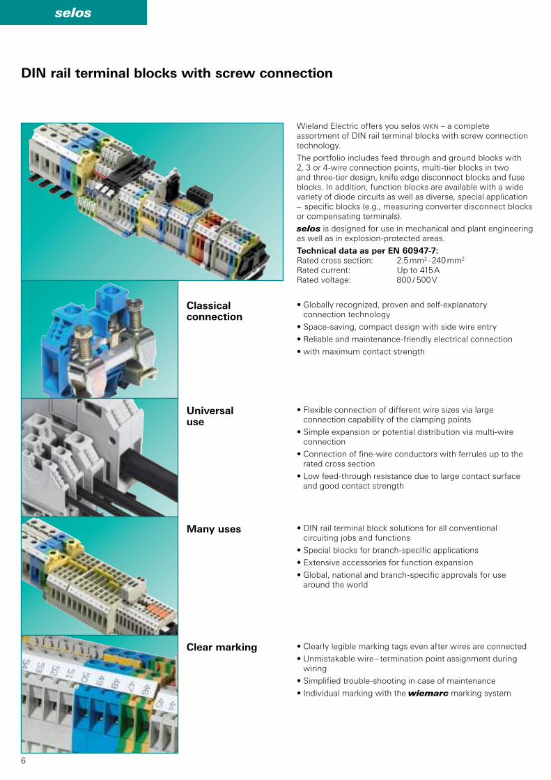
DIN rail terminal blocks with screw connection
Wieland Electric offers you selos WKN – a complete assortment of DIN rail terminal blocks with screw connection technology.
The portfolio includes feed through and ground blocks with 2, 3 or 4-wire connection points, multi-tier blocks in two and three-tier design, knife edge disconnect blocks and fuse blocks. In addition, function blocks are available with a wide variety of diode circuits as well as diverse, special application – specific blocks (e.g., measuring converter disconnect blocks or compensating terminals).
selos is designed for use in mechanical and plant engineering as well as in explosion-protected areas.
Technical data as per EN 60947-7:Rated cross section: 2.5 mm2 - 240 mm2
Rated current: Up to 415 ARated voltage: 800 / 500 V
Classical connection
• Globally recognized, proven and self-explanatory connection technology
• Space-saving, compact design with side wire entry
• Reliable and maintenance-friendly electrical connection
• with maximum contact strength
Universal use
• Flexible connection of different wire sizes via large connection capability of the clamping points
• Simple expansion or potential distribution via multi-wire connection
• Connection of fine-wire conductors with ferrules up to the rated cross section
• Low feed-through resistance due to large contact surface and good contact strength
Many uses • DIN rail terminal block solutions for all conventional circuiting jobs and functions
• Special blocks for branch-specific applications
• Extensive accessories for function expansion
• Global, national and branch-specific approvals for use around the world
Clear marking • Clearly legible marking tags even after wires are connected
• Unmistakable wire – termination point assignment during wiring
• Simplified trouble-shooting in case of maintenance
• Individual marking with the wiemarc marking system
7
selos
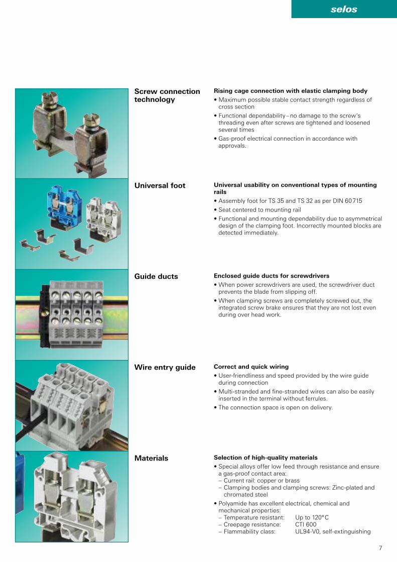
Universal foot
Guide ducts
Wire entry guide
Materials
Screw connection technology
Selection of high-quality materials
• Special alloys offer low feed through resistance and ensure a gas-proof contact area:– Current rail: copper or brass– Clamping bodies and clamping screws: Zinc-plated and
chromated steel
• Polyamide has excellent electrical, chemical and mechanical properties:– Temperature resistant: Up to 120° C– Creepage resistance: CTI 600– Flammability class: UL94-V0, self-extinguishing
Enclosed guide ducts for screwdrivers
• When power screwdrivers are used, the screwdriver duct prevents the blade from slipping off.
• When clamping screws are completely screwed out, the integrated screw brake ensures that they are not lost even during over head work.
Correct and quick wiring
• User-friendliness and speed provided by the wire guide during connection
• Multi-stranded and fine-stranded wires can also be easily inserted in the terminal without ferrules.
• The connection space is open on delivery.
Rising cage connection with elastic clamping body
• Maximum possible stable contact strength regardless of cross section
• Functional dependability – no damage to the screw‘s threading even after screws are tightened and loosened several times
• Gas-proof electrical connection in accordance with approvals.
Universal usability on conventional types of mounting rails
• Assembly foot for TS 35 and TS 32 as per DIN 60 715
• Seat centered to mounting rail
• Functional and mounting dependability due to asymmetrical design of the clamping foot. Incorrectly mounted blocks are detected immediately.
8
selos
DIN rail terminal blocks with screw connection
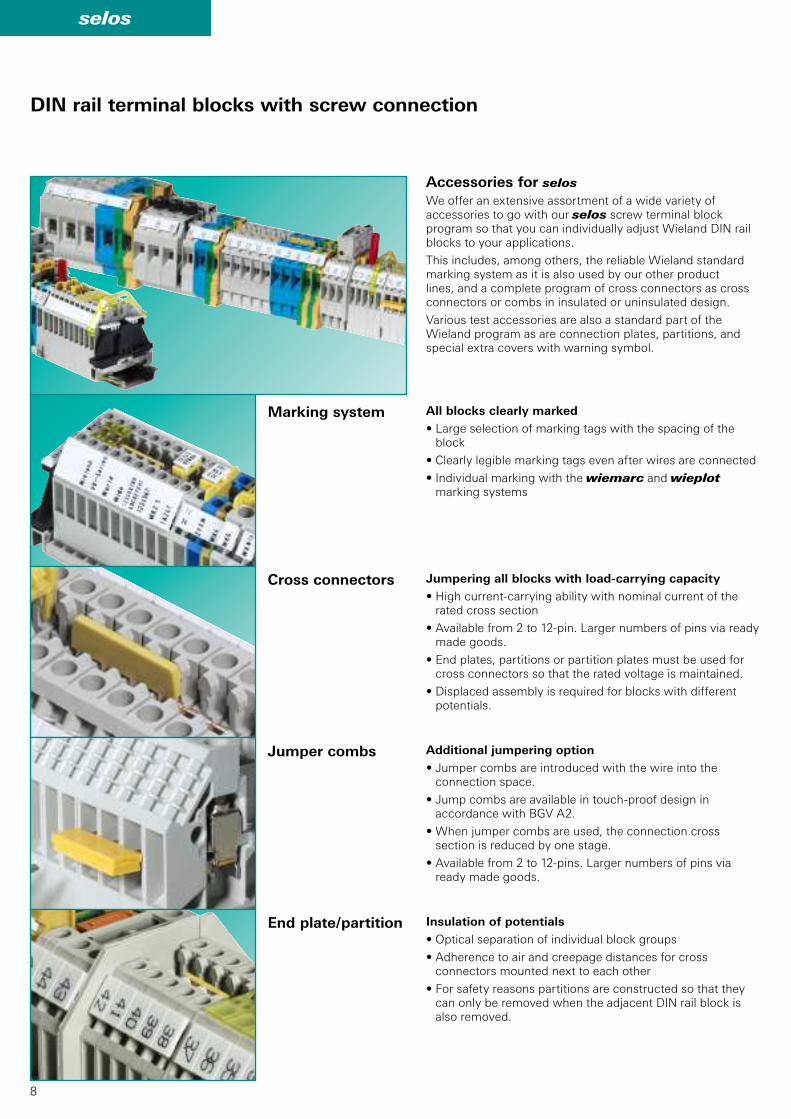
Accessories for selos
We offer an extensive assortment of a wide variety of accessories to go with our selos screw terminal block program so that you can individually adjust Wieland DIN rail blocks to your applications.
This includes, among others, the reliable Wieland standard marking system as it is also used by our other product lines, and a complete program of cross connectors as cross connectors or combs in insulated or uninsulated design.
Various test accessories are also a standard part of the Wieland program as are connection plates, partitions, and special extra covers with warning symbol.
Marking system
Cross connectors
Jumper combs
End plate / partition
All blocks clearly marked
• Large selection of marking tags with the spacing of the block
• Clearly legible marking tags even after wires are connected
• Individual marking with the wiemarc and wieplot marking systems
Jumpering all blocks with load-carrying capacity
• High current-carrying ability with nominal current of the rated cross section
• Available from 2 to 12-pin. Larger numbers of pins via ready made goods.
• End plates, partitions or partition plates must be used for cross connectors so that the rated voltage is maintained.
• Displaced assembly is required for blocks with different potentials.
Additional jumpering option
• Jumper combs are introduced with the wire into the connection space.
• Jump combs are available in touch-proof design in accordance with BGV A2.
• When jumper combs are used, the connection cross section is reduced by one stage.
• Available from 2 to 12-pins. Larger numbers of pins via ready made goods.
Insulation of potentials
• Optical separation of individual block groups
• Adherence to air and creepage distances for cross connectors mounted next to each other
• For safety reasons partitions are constructed so that they can only be removed when the adjacent DIN rail block is also removed.
9
selos
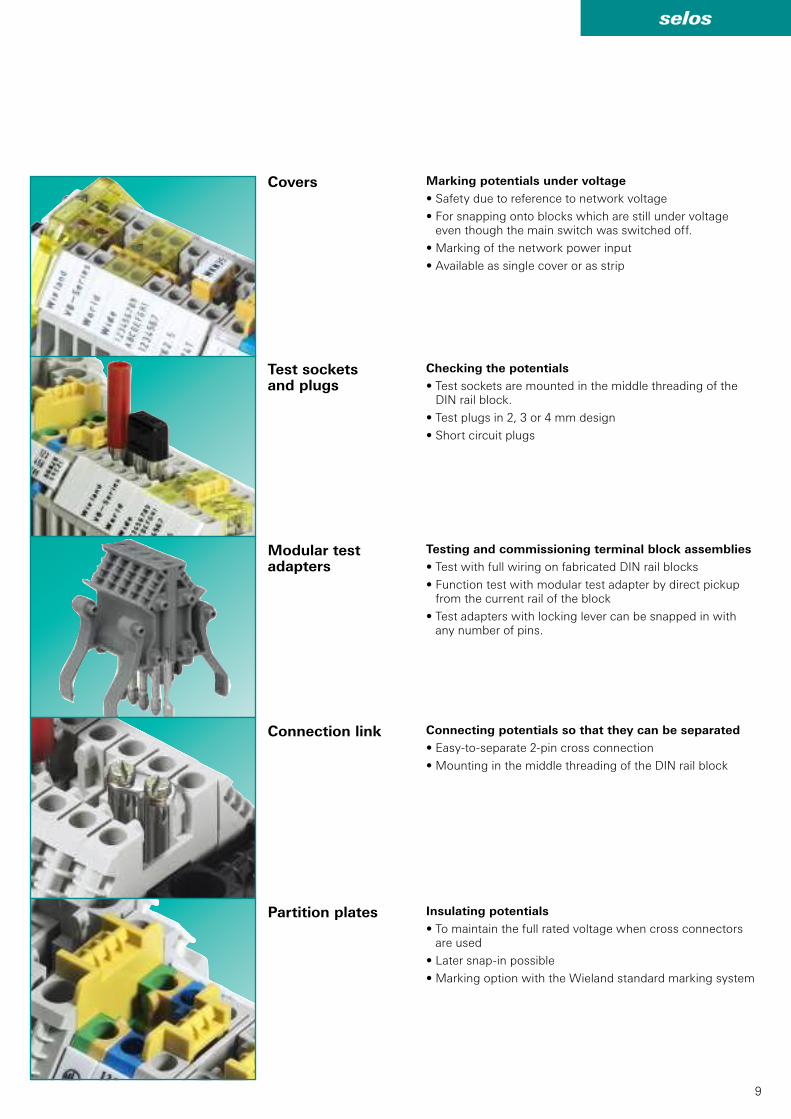
Marking potentials under voltage
• Safety due to reference to network voltage
• For snapping onto blocks which are still under voltage even though the main switch was switched off.
• Marking of the network power input
• Available as single cover or as strip
Test sockets and plugs
Checking the potentials
• Test sockets are mounted in the middle threading of the DIN rail block.
• Test plugs in 2, 3 or 4 mm design
• Short circuit plugs
Modular test adapters
Testing and commissioning terminal block assemblies
• Test with full wiring on fabricated DIN rail blocks
• Function test with modular test adapter by direct pickup from the current rail of the block
• Test adapters with locking lever can be snapped in with any number of pins.
Connection link Connecting potentials so that they can be separated
• Easy-to-separate 2-pin cross connection
• Mounting in the middle threading of the DIN rail block
Partition plates Insulating potentials
• To maintain the full rated voltage when cross connectors are used
• Later snap-in possible
• Marking option with the Wieland standard marking system
Covers
10
selos
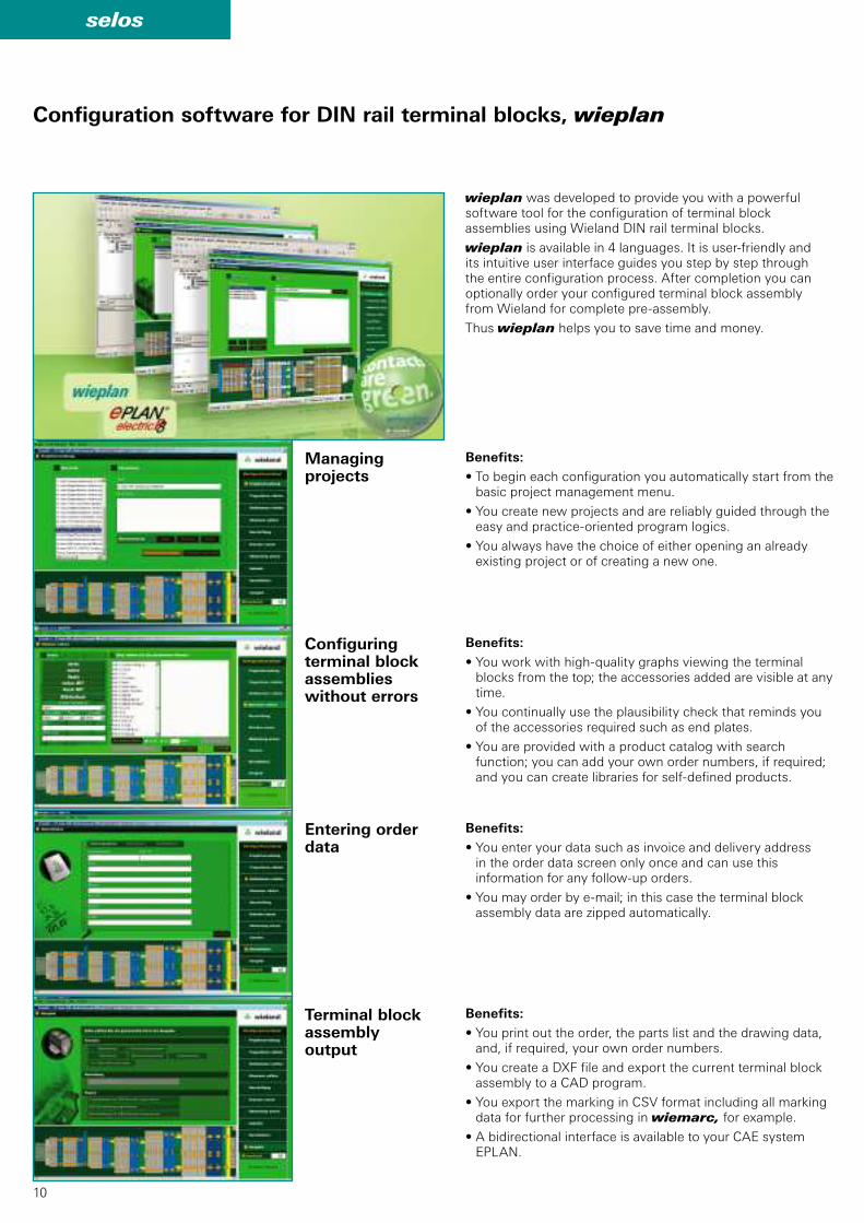
Configuration software for DIN rail terminal blocks, wieplan
wieplan was developed to provide you with a powerful software tool for the configuration of terminal block assemblies using Wieland DIN rail terminal blocks.
wieplan is available in 4 languages. It is user-friendly and its intuitive user interface guides you step by step through the entire configuration process. After completion you can optionally order your configured terminal block assembly from Wieland for complete pre-assembly.
Thus wieplan helps you to save time and money.
Benefits:
• To begin each configuration you automatically start from the basic project management menu.
• You create new projects and are reliably guided through the easy and practice-oriented program logics.
• You always have the choice of either opening an already existing project or of creating a new one.
Benefits:
• You work with high-quality graphs viewing the terminal blocks from the top; the accessories added are visible at any time.
• You continually use the plausibility check that reminds you of the accessories required such as end plates.
• You are provided with a product catalog with search function; you can add your own order numbers, if required; and you can create libraries for self-defined products.
Benefits:
• You enter your data such as invoice and delivery address in the order data screen only once and can use this information for any follow-up orders.
• You may order by e-mail; in this case the terminal block assembly data are zipped automatically.
Benefits:
• You print out the order, the parts list and the drawing data, and, if required, your own order numbers.
• You create a DXF file and export the current terminal block assembly to a CAD program.
• You export the marking in CSV format including all marking data for further processing in wiemarc, for example.
• A bidirectional interface is available to your CAE system EPLAN.
Managingprojects
Configuring terminal block assemblies without errors
Entering order data
Terminal block assembly output
11
selos
selos – fasis
wieplot
wiemarc
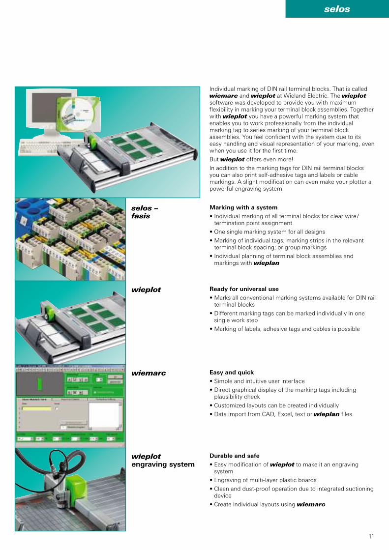
Individual marking of DIN rail terminal blocks. That is called wiemarc and wieplot at Wieland Electric. The wieplot software was developed to provide you with maximum flexibility in marking your terminal block assemblies. Together with wieplot you have a powerful marking system that enables you to work professionally from the individual marking tag to series marking of your terminal block assemblies. You feel confident with the system due to its easy handling and visual representation of your marking, even when you use it for the first time.
But wieplot offers even more!
In addition to the marking tags for DIN rail terminal blocks you can also print self-adhesive tags and labels or cable markings. A slight modification can even make your plotter a powerful engraving system.
Marking with a system
• Individual marking of all terminal blocks for clear wire /termination point assignment
• One single marking system for all designs
• Marking of individual tags; marking strips in the relevant terminal block spacing; or group markings
• Individual planning of terminal block assemblies and markings with wieplan
Ready for universal use
• Marks all conventional marking systems available for DIN rail terminal blocks
• Different marking tags can be marked individually in one single work step
• Marking of labels, adhesive tags and cables is possible
Easy and quick
• Simple and intuitive user interface
• Direct graphical display of the marking tags including plausibility check
• Customized layouts can be created individually
• Data import from CAD, Excel, text or wieplan files
Durable and safe
• Easy modification of wieplot to make it an engraving system
• Engraving of multi-layer plastic boards
• Clean and dust-proof operation due to integrated suctioning device
• Create individual layouts using wiemarc
wieplot engraving system

selos
12
29
321
17
4
18
5
96
8
7
12
11
10
13
16
15
14
30
23
19
24
20
21
2627
22
25
28
DIN rail terminal blocks with screw connection
13
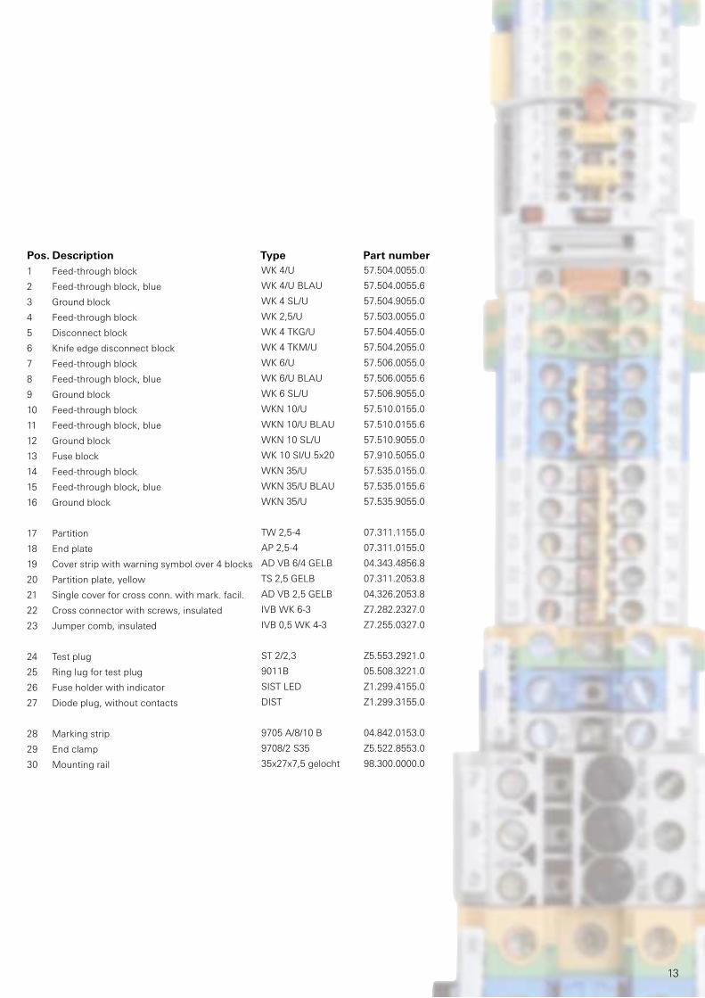
WK 4/U 57.504.0055.0
WK 4/U BLAU 57.504.0055.6
WK 4 SL/U 57.504.9055.0
WK 2,5/U 57.503.0055.0
WK 4 TKG/U 57.504.4055.0
WK 4 TKM/U 57.504.2055.0
WK 6/U 57.506.0055.0
WK 6/U BLAU 57.506.0055.6
WK 6 SL/U 57.506.9055.0
WKN 10/U 57.510.0155.0
WKN 10/U BLAU 57.510.0155.6
WKN 10 SL/U 57.510.9055.0
WK 10 SI/U 5x20 57.910.5055.0
WKN 35/U 57.535.0155.0
WKN 35/U BLAU 57.535.0155.6
WKN 35/U 57.535.9055.0
TW 2,5-4 07.311.1155.0
AP 2,5-4 07.311.0155.0
AD VB 6/4 GELB 04.343.4856.8
TS 2,5 GELB 07.311.2053.8
AD VB 2,5 GELB 04.326.2053.8
IVB WK 6-3 Z7.282.2327.0
IVB 0,5 WK 4-3 Z7.255.0327.0
ST 2/2,3 Z5.553.2921.0
9011B 05.508.3221.0
SIST LED Z1.299.4155.0
DIST Z1.299.3155.0
9705 A/8/10 B 04.842.0153.0
9708/2 S35 Z5.522.8553.0
35x27x7,5 gelocht 98.300.0000.0
Pos. Description Type Part number
1 Feed-through block
2 Feed-through block, blue
3 Ground block
4 Feed-through block
5 Disconnect block
6 Knife edge disconnect block
7 Feed-through block
8 Feed-through block, blue
9 Ground block
10 Feed-through block
11 Feed-through block, blue
12 Ground block
13 Fuse block
14 Feed-through block
15 Feed-through block, blue
16 Ground block
17 Partition
18 End plate
19 Cover strip with warning symbol over 4 blocks
20 Partition plate, yellow
21 Single cover for cross conn. with mark. facil.
22 Cross connector with screws, insulated
23 Jumper comb, insulated
24 Test plug
25 Ring lug for test plug
26 Fuse holder with indicator
27 Diode plug, without contacts
28 Marking strip
29 End clamp
30 Mounting rail
14
selos
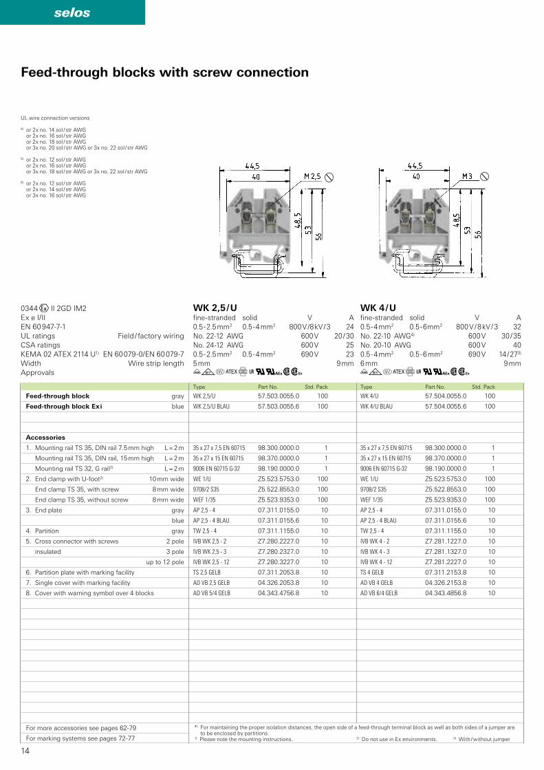
WK 4/U 57.504.0055.0 100
WK 4/U BLAU 57.504.0055.6 100
35 x 27 x 7,5 EN 60715 98.300.0000.0 1
35 x 27 x 15 EN 60715 98.370.0000.0 1
9006 EN 60715 G-32 98.190.0000.0 1
WE 1/U Z5.523.5753.0 100
9708/2 S35 Z5.522.8553.0 100
WEF 1/35 Z5.523.9353.0 100
AP 2,5 - 4 07.311.0155.0 10
AP 2,5 - 4 BLAU 07.311.0155.6 10
TW 2,5 - 4 07.311.1155.0 10
IVB WK 4 - 2 Z7.281.1227.0 10
IVB WK 4 - 3 Z7.281.1327.0 10
IVB WK 4 - 12 Z7.281.2227.0 10
TS 4 GELB 07.311.2153.8 10
AD VB 4 GELB 04.326.2153.8 10
AD VB 6/4 GELB 04.343.4856.8 10
WK 2,5/U 57.503.0055.0 100
WK 2,5/U BLAU 57.503.0055.6 100
35 x 27 x 7,5 EN 60715 98.300.0000.0 1
35 x 27 x 15 EN 60715 98.370.0000.0 1
9006 EN 60715 G-32 98.190.0000.0 1
WE 1/U Z5.523.5753.0 100
9708/2 S35 Z5.522.8553.0 100
WEF 1/35 Z5.523.9353.0 100
AP 2,5 - 4 07.311.0155.0 10
AP 2,5 - 4 BLAU 07.311.0155.6 10
TW 2,5 - 4 07.311.1155.0 10
IVB WK 2,5 - 2 Z7.280.2227.0 10
IVB WK 2,5 - 3 Z7.280.2327.0 10
IVB WK 2,5 - 12 Z7.280.3227.0 10
TS 2,5 GELB 07.311.2053.8 10
AD VB 2,5 GELB 04.326.2053.8 10
AD VB 5/4 GELB 04.343.4756.8 10
ügoCf+q#wh ügoCf+q#wh
0344OII 2GD IM2
Ex e I/II
EN 60 947-7-1
KEMA 02 ATEX 2114 U1) EN 60 079-0/EN 60 079-7
Feed-through blocks with screw connection
Type Part No. Std. PackType Part No. Std. Pack
Feed-through block gray
Feed-through block Ex i blue
Accessories
1. Mounting rail TS 35, DIN rail 7.5 mm high L = 2 m
Mounting rail TS 35, DIN rail, 15 mm high L = 2 m
Mounting rail TS 32, G rail2) L = 2 m
2. End clamp with U-foot2) 10 mm wide
End clamp TS 35, with screw 8 mm wide
End clamp TS 35, without screw 8 mm wide
3. End plate gray
blue
4. Partition gray
5. Cross connector with screws 2 pole
insulated 3 pole
up to 12 pole
6. Partition plate with marking facility
7. Single cover with marking facility
8. Cover with warning symbol over 4 blocks
For more accessories see pages 62-79
For marking systems see pages 72-77
*) For maintaining the proper isolation distances, the open side of a feed-through terminal block as well as both sides of a jumper are to be enclosed by partitions.
1) Please note the mounting instructions. 2) Do not use in Ex environments. 3) With / without jumper
UL wire connection versions
4) or 2x no. 14 sol / str AWG or 2x no. 16 sol / str AWG or 2x no. 18 sol / str AWG or 3x no. 20 sol / str AWG or 3x no. 22 sol / str AWG
5) or 2x no. 12 sol / str AWG or 2x no. 16 sol / str AWG or 3x no. 18 sol / str AWG or 3x no. 22 sol / str AWG
6) or 2x no. 12 sol / str AWG or 2x no. 14 sol / str AWG or 3x no. 16 sol / str AWG
UL ratings Field / factory wiring
CSA ratings
Width Wire strip length
Approvals
WK 2,5 / Ufine-stranded solid V A
0.5 - 2.5 mm2 0.5 - 4 mm2 800 V /8 kV / 3 24
No. 22-12 AWG 600 V 20 / 30
No. 24-12 AWG 600 V 25
0.5 - 2.5 mm2 0.5 - 4 mm2 690 V 23
5 mm 9 mm
WK 4 / Ufine-stranded solid V A
0.5 - 4 mm2 0.5 - 6 mm2 800 V / 8 kV / 3 32
No. 22-10 AWG4) 600 V 30 / 35
No. 20-10 AWG 600 V 40
0.5 - 4 mm2 0.5 - 6 mm2 690 V 14 / 273)
6 mm 9 mm
15
selos
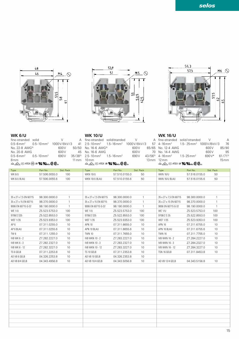
WKN 16/U 57.516.0155.0 50
WKN 16/U BLAU 57.516.0155.6 50
35 x 27 x 7,5 EN 60715 98.300.0000.0 1
35 x 27 x 15 EN 60715 98.370.0000.0 1
9006 EN 60715 G-32 98.190.0000.0 1
WE 1/U Z5.523.5753.0 100
9708/2 S 35 Z5.522.8553.0 100
WEF 1/35 Z5.523.9353.0 100
APN 16 07.311.6755.0 10
APN 16 BLAU 07.311.6755.6 10
TWN 16 07.311.7755.0 10
IVB WKN 16 - 2 Z7.284.2227.0 10
IVB WKN 16 - 3 Z7.284.2327.0 10
IVB WKN 16 - 12 Z7.284.3227.0 10
TSN 16 GELB 07.311.8453.8 10
AD VB 12/4 GELB 04.343.5156.8 10
WKN 10/U 57.510.0155.0 50
WKN 10/U BLAU 57.510.0155.6 50
35 x 27 x 7,5 EN 60715 98.300.0000.0 1
35 x 27 x 15 EN 60715 98.370.0000.0 1
9006 EN 60715 G-32 98.190.0000.0 1
WE 1/U Z5.523.5753.0 100
9708/2 S35 Z5.522.8553.0 100
WEF 1/35 Z5.523.9353.0 100
APN 10 07.311.6655.0 10
APN 10 BLAU 07.311.6655.6 10
TWN 10 07.311.7655.0 10
IVB WKN 10 - 2 Z7.283.2227.0 10
IVB WKN 10 - 3 Z7.283.2327.0 10
IVB WKN 10 - 12 Z7.283.3227.0 10
TS 10 GELB 07.311.2353.8 10
AD VB 10 GELB 04.326.2353.8 10
AD VB 10/4 GELB 04.343.5056.8 10
WK 6/U 57.506.0055.0 100
WK 6/U BLAU 57.506.0055.6 100
35 x 27 x 7,5 EN 60715 98.300.0000.0 1
35 x 27 x 15 EN 60715 98.370.0000.0 1
9006 EN 60715 G-32 98.190.0000.0 1
WE 1/U Z5.523.5753.0 100
9708/2 S35 Z5.522.8553.0 100
WEF 1/35 Z5.523.9353.0 100
AP 6 07.311.0255.0 10
AP 6 BLAU 07.311.0255.6 10
TW 6 07.311.1255.0 10
IVB WK 6 - 2 Z7.282.2227.0 10
IVB WK 6 - 3 Z7.282.2327.0 10
IVB WK 6 - 12 Z7.282.3227.0 10
TS 6 GELB 07.311.2253.8 10
AD VB 6 GELB 04.326.2253.8 10
AD VB 8/4 GELB 04.343.4956.8 10
ügoC+q#wh ügoC+q#whügoCf+q#whType Part No. Std. PackType Part No. Std. PackType Part No. Std. Pack
WK 10 / U fine-stranded solid/standed V A
2.5 - 10 mm2 1.5 - 16 mm2 1000 V / 8 kV / 3 57
No. 16-6 AWG6) 600 V 65 / 65
No. 16-6 AWG 600 V 70
2.5 - 10 mm2 1.5 - 16 mm2 690 V 43 / 563)
10 mm 13 mm
WK 16 / Ufine-stranded solid / stranded V A
4 - 16 mm2 1.5 - 25 mm2 1000 V /8 kV / 3 76
No. 12-4 AWG 600 V 85 / 90
No. 14-4 AWG 600 V 95
4 - 16 mm2 1.5 - 25 mm2 690 V* 61 / 713)
12 mm 15 mm
WK 6 / Ufine-stranded solid V A
0.5 - 6 mm2 0.5 - 10 mm2 1000 V / 8 kV / 3 41
No. 22-8 AWG5) 600 V 50 / 50
No. 20-8 AWG 600 V 45
0.5 - 6 mm2 0.5 - 10 mm2 690 V 35 / 383)
8 mm 11 mm
16
selos
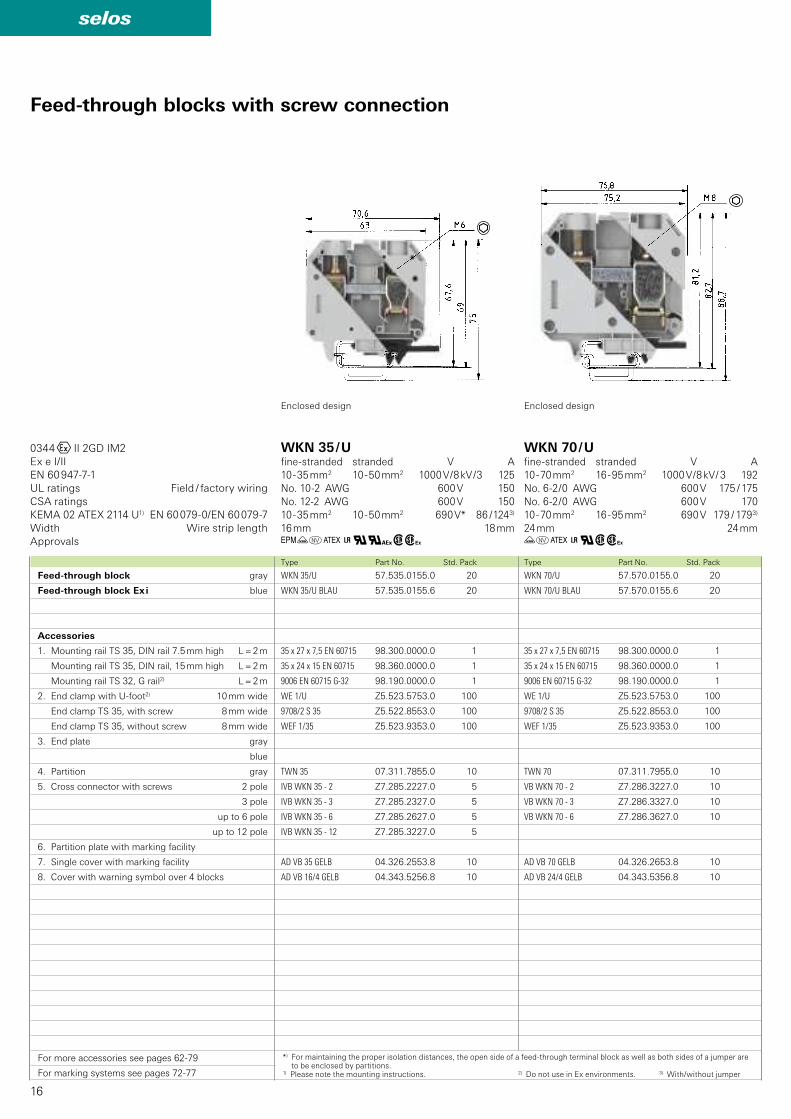
WKN 70/U 57.570.0155.0 20
WKN 70/U BLAU 57.570.0155.6 20
35 x 27 x 7,5 EN 60715 98.300.0000.0 1
35 x 24 x 15 EN 60715 98.360.0000.0 1
9006 EN 60715 G-32 98.190.0000.0 1
WE 1/U Z5.523.5753.0 100
9708/2 S 35 Z5.522.8553.0 100
WEF 1/35 Z5.523.9353.0 100
TWN 70 07.311.7955.0 10
VB WKN 70 - 2 Z7.286.3227.0 10
VB WKN 70 - 3 Z7.286.3327.0 10
VB WKN 70 - 6 Z7.286.3627.0 10
AD VB 70 GELB 04.326.2653.8 10
AD VB 24/4 GELB 04.343.5356.8 10
WKN 35/U 57.535.0155.0 20
WKN 35/U BLAU 57.535.0155.6 20
35 x 27 x 7,5 EN 60715 98.300.0000.0 1
35 x 24 x 15 EN 60715 98.360.0000.0 1
9006 EN 60715 G-32 98.190.0000.0 1
WE 1/U Z5.523.5753.0 100
9708/2 S 35 Z5.522.8553.0 100
WEF 1/35 Z5.523.9353.0 100
TWN 35 07.311.7855.0 10
IVB WKN 35 - 2 Z7.285.2227.0 5
IVB WKN 35 - 3 Z7.285.2327.0 5
IVB WKN 35 - 6 Z7.285.2627.0 5
IVB WKN 35 - 12 Z7.285.3227.0 5
AD VB 35 GELB 04.326.2553.8 10
AD VB 16/4 GELB 04.343.5256.8 10
GüoC+q#wh üoC+qwh
0344OII 2GD IM2
Ex e I/II
EN 60 947-7-1
KEMA 02 ATEX 2114 U1) EN 60 079-0/EN 60 079-7
Type Part No. Std. PackType Part No. Std. Pack
Feed-through blocks with screw connection
Feed-through block gray
Feed-through block Ex i blue
Accessories
1. Mounting rail TS 35, DIN rail 7.5 mm high L = 2 m
Mounting rail TS 35, DIN rail, 15 mm high L = 2 m
Mounting rail TS 32, G rail2) L = 2 m
2. End clamp with U-foot2) 10 mm wide
End clamp TS 35, with screw 8 mm wide
End clamp TS 35, without screw 8 mm wide
3. End plate gray
blue
4. Partition gray
5. Cross connector with screws 2 pole
3 pole
up to 6 pole
up to 12 pole
6. Partition plate with marking facility
7. Single cover with marking facility
8. Cover with warning symbol over 4 blocks
For more accessories see pages 62-79
For marking systems see pages 72-77
UL ratings Field / factory wiring
CSA ratings
Width Wire strip length
Approvals
WKN 35 / Ufine-stranded stranded V A
10 - 35 mm2 10 - 50 mm2 1000 V / 8 kV / 3 125
No. 10-2 AWG 600 V 150
No. 12-2 AWG 600 V 150
10 - 35 mm2 10 - 50 mm2 690 V* 86 / 1243)
16 mm 18 mm
WKN 70 / Ufine-stranded stranded V A
10 - 70 mm2 16 - 95 mm2 1000 V / 8 kV / 3 192
No. 6-2 / 0 AWG 600 V 175 / 175
No. 6-2 / 0 AWG 600 V 170
10 - 70 mm2 16 - 95 mm2 690 V 179 / 1793)
24 mm 24 mm
*) For maintaining the proper isolation distances, the open side of a feed-through terminal block as well as both sides of a jumper are to be enclosed by partitions.
1) Please note the mounting instructions. 2) Do not use in Ex environments. 3) With/without jumper
Enclosed design Enclosed design
17
selos
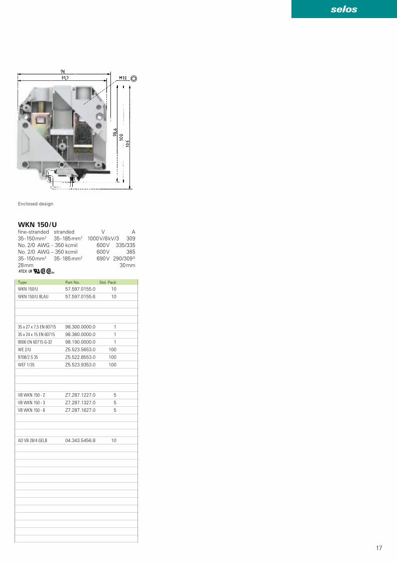
WKN 150/U 57.597.0155.0 10
WKN 150/U BLAU 57.597.0155.6 10
35 x 27 x 7,5 EN 60715 98.300.0000.0 1
35 x 24 x 15 EN 60715 98.360.0000.0 1
9006 EN 60715 G-32 98.190.0000.0 1
WE 2/U Z5.523.5653.0 100
9708/2 S 35 Z5.522.8553.0 100
WEF 1/35 Z5.523.9353.0 100
VB WKN 150 - 2 Z7.287.1227.0 5
VB WKN 150 - 3 Z7.287.1327.0 5
VB WKN 150 - 6 Z7.287.1627.0 5
AD VB 28/4 GELB 04.343.5456.8 10
C+qwhType Part No. Std. Pack
WKN 150 / Ufine-stranded stranded V A
35 - 150 mm2 35 - 185 mm2 1000 V / 8 kV /3 309
No. 2/0 AWG – 350 kcmil 600 V 335 / 335
No. 2/0 AWG – 350 kcmil 600 V 365
35 - 150 mm2 35 - 185 mm2 690 V 290 /3093)
28 mm 30 mm
Enclosed design
18
selos
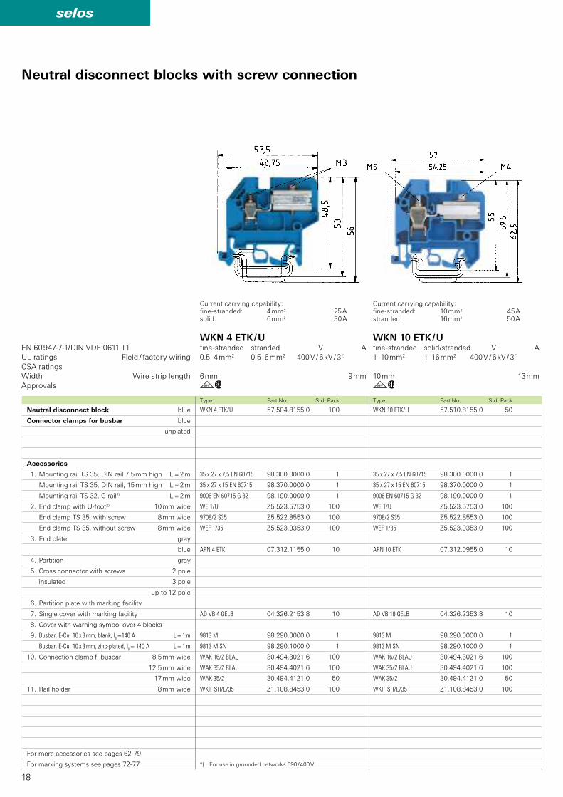
WKN 10 ETK/U 57.510.8155.0 50
35 x 27 x 7,5 EN 60715 98.300.0000.0 1
35 x 27 x 15 EN 60715 98.370.0000.0 1
9006 EN 60715 G-32 98.190.0000.0 1
WE 1/U Z5.523.5753.0 100
9708/2 S35 Z5.522.8553.0 100
WEF 1/35 Z5.523.9353.0 100
APN 10 ETK 07.312.0955.0 10
AD VB 10 GELB 04.326.2353.8 10
9813 M 98.290.0000.0 1
9813 M SN 98.290.1000.0 1
WAK 16/2 BLAU 30.494.3021.6 100
WAK 35/2 BLAU 30.494.4021.6 100
WAK 35/2 30.494.4121.0 50
WKIF SH/E/35 Z1.108.8453.0 100
WKN 4 ETK/U 57.504.8155.0 100
35 x 27 x 7,5 EN 60715 98.300.0000.0 1
35 x 27 x 15 EN 60715 98.370.0000.0 1
9006 EN 60715 G-32 98.190.0000.0 1
WE 1/U Z5.523.5753.0 100
9708/2 S35 Z5.522.8553.0 100
WEF 1/35 Z5.523.9353.0 100
APN 4 ETK 07.312.1155.0 10
AD VB 4 GELB 04.326.2153.8 10
9813 M 98.290.0000.0 1
9813 M SN 98.290.1000.0 1
WAK 16/2 BLAU 30.494.3021.6 100
WAK 35/2 BLAU 30.494.4021.6 100
WAK 35/2 30.494.4121.0 50
WKIF SH/E/35 Z1.108.8453.0 100
gw gw
EN 60 947-7-1/DIN VDE 0611 T1
Type Part No. Std. PackType Part No. Std. Pack
Neutral disconnect blocks with screw connection
Neutral disconnect block blue
Connector clamps for busbar blue
unplated
Accessories
1. Mounting rail TS 35, DIN rail 7.5 mm high L = 2 m
Mounting rail TS 35, DIN rail, 15 mm high L = 2 m
Mounting rail TS 32, G rail2) L = 2 m
2. End clamp with U-foot2) 10 mm wide
End clamp TS 35, with screw 8 mm wide
End clamp TS 35, without screw 8 mm wide
3. End plate gray
blue
4. Partition gray
5. Cross connector with screws 2 pole
insulated 3 pole
up to 12 pole
6. Partition plate with marking facility
7. Single cover with marking facility
8. Cover with warning symbol over 4 blocks
9. Busbar, E-Cu, 10 x 3 mm, blank, IN=140 A L = 1 m
Busbar, E-Cu, 10 x 3 mm, zinc-plated, IN= 140 A L = 1 m
10. Connection clamp f. busbar 8.5 mm wide
12.5 mm wide
17 mm wide
11. Rail holder 8 mm wide
For more accessories see pages 62-79
For marking systems see pages 72-77
UL ratings Field / factory wiring
CSA ratings
Width Wire strip length
Approvals
WKN 4 ETK / Ufine-stranded stranded V A
0.5 - 4 mm2 0.5 - 6 mm2 400 V / 6 kV / 3*)
6 mm 9 mm
WKN 10 ETK / Ufine-stranded solid/stranded V A
1 - 10 mm2 1 - 16 mm2 400 V / 6 kV / 3*)
10 mm 13 mm
*) For use in grounded networks 690 / 400 V
Current carrying capability:fine-stranded: 10 mm2 45 Astranded: 16 mm2 50 A
Current carrying capability:fine-stranded: 4 mm2 25 Asolid: 6 mm2 30 A
19
selos
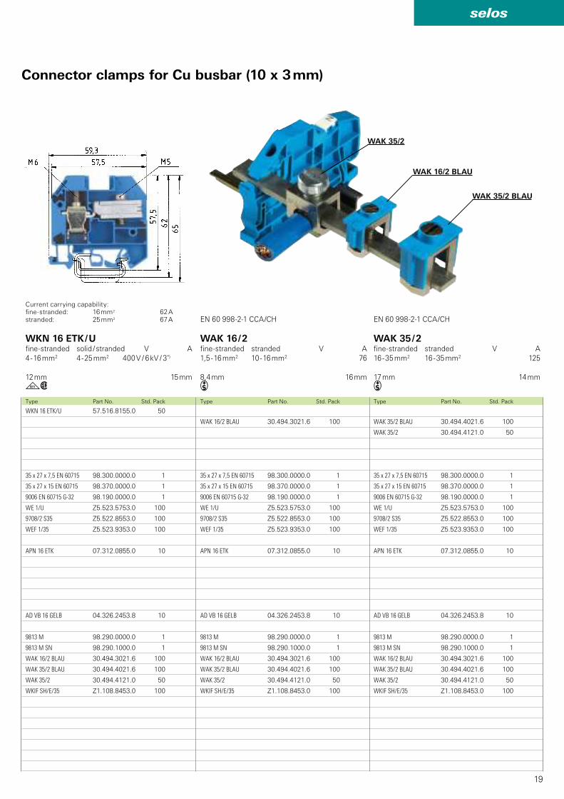
WAK 35/2 BLAU 30.494.4021.6 100
WAK 35/2 30.494.4121.0 50
35 x 27 x 7,5 EN 60715 98.300.0000.0 1
35 x 27 x 15 EN 60715 98.370.0000.0 1
9006 EN 60715 G-32 98.190.0000.0 1
WE 1/U Z5.523.5753.0 100
9708/2 S35 Z5.522.8553.0 100
WEF 1/35 Z5.523.9353.0 100
APN 16 ETK 07.312.0855.0 10
AD VB 16 GELB 04.326.2453.8 10
9813 M 98.290.0000.0 1
9813 M SN 98.290.1000.0 1
WAK 16/2 BLAU 30.494.3021.6 100
WAK 35/2 BLAU 30.494.4021.6 100
WAK 35/2 30.494.4121.0 50
WKIF SH/E/35 Z1.108.8453.0 100
WAK 16/2 BLAU 30.494.3021.6 100
35 x 27 x 7,5 EN 60715 98.300.0000.0 1
35 x 27 x 15 EN 60715 98.370.0000.0 1
9006 EN 60715 G-32 98.190.0000.0 1
WE 1/U Z5.523.5753.0 100
9708/2 S35 Z5.522.8553.0 100
WEF 1/35 Z5.523.9353.0 100
APN 16 ETK 07.312.0855.0 10
AD VB 16 GELB 04.326.2453.8 10
9813 M 98.290.0000.0 1
9813 M SN 98.290.1000.0 1
WAK 16/2 BLAU 30.494.3021.6 100
WAK 35/2 BLAU 30.494.4021.6 100
WAK 35/2 30.494.4121.0 50
WKIF SH/E/35 Z1.108.8453.0 100
WAK 16/2 BLAU
WAK 35/2
WKN 16 ETK/U 57.516.8155.0 50
35 x 27 x 7,5 EN 60715 98.300.0000.0 1
35 x 27 x 15 EN 60715 98.370.0000.0 1
9006 EN 60715 G-32 98.190.0000.0 1
WE 1/U Z5.523.5753.0 100
9708/2 S35 Z5.522.8553.0 100
WEF 1/35 Z5.523.9353.0 100
APN 16 ETK 07.312.0855.0 10
AD VB 16 GELB 04.326.2453.8 10
9813 M 98.290.0000.0 1
9813 M SN 98.290.1000.0 1
WAK 16/2 BLAU 30.494.3021.6 100
WAK 35/2 BLAU 30.494.4021.6 100
WAK 35/2 30.494.4121.0 50
WKIF SH/E/35 Z1.108.8453.0 100
i igw
WAK 35/2 BLAU
EN 60 998-2-1 CCA/CHEN 60 998-2-1 CCA/CH
Type Part No. Std. PackType Part No. Std. PackType Part No. Std. Pack
WAK 16 / 2fine-stranded stranded V A
1,5 - 16 mm2 10 - 16 mm2 76
8,4 mm 16 mm
WAK 35 / 2fine-stranded stranded V A
16 - 35 mm2 16 - 35 mm2 125
17 mm 14 mm
WKN 16 ETK / Ufine-stranded solid / stranded V A
4 - 16 mm2 4 - 25 mm2 400 V / 6 kV / 3*)
12 mm 15 mm
Current carrying capability:fine-stranded: 16 mm2 62 Astranded: 25 mm2 67 A
Connector clamps for Cu busbar (10 x 3 mm)
20
selos
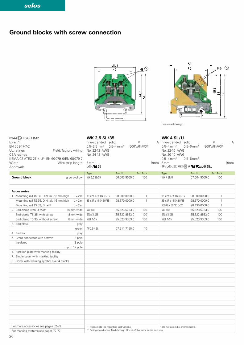
WK 4 SL/U 57.504.9055.0 100
35 x 27 x 7,5 EN 60715 98.300.0000.0 1
35 x 27 x 15 EN 60715 98.370.0000.0 1
9006 EN 60715 G-32 98.190.0000.0 1
WE 1/U Z5.523.5753.0 100
9708/2 S35 Z5.522.8553.0 100
WEF 1/35 Z5.523.9353.0 100
WK 2,5 SL/35 56.503.9055.0 100
35 x 27 x 7,5 EN 60715 98.300.0000.0 1
35 x 27 x 15 EN 60715 98.370.0000.0 1
WE 1/U Z5.523.5753.0 100
9708/2 S35 Z5.522.8553.0 100
WEF 1/35 Z5.523.9353.0 100
AP 2,5-4 SL 07.311.7155.0 10
gqw GgoCf+q#wh
0344OII 2GD IM2
Ex e I/II
EN 60 947-7-2
KEMA 02 ATEX 2114 U1) EN 60 079-0/EN 60 079-7
Type Part No. Std. PackType Part No. Std. Pack
Ground blocks with screw connection
Ground block green/yellow
Accessories
1. Mounting rail TS 35, DIN rail 7.5 mm high L = 2 m
Mounting rail TS 35, DIN rail, 15 mm high L = 2 m
Mounting rail TS 32, G rail2) L = 2 m
2. End clamp with U-foot2) 10 mm wide
End clamp TS 35, with screw 8 mm wide
End clamp TS 35, without screw 8 mm wide
3. End plate gray
green
4. Partition gray
5. Cross connector with screws 2 pole
insulated 3 pole
up to 12 pole
6. Partition plate with marking facility
7. Single cover with marking facility
8. Cover with warning symbol over 4 blocks
For more accessories see pages 62-79
For marking systems see pages 72-77
UL ratings Field / factory wiring
CSA ratings
Width Wire strip length
Approvals
WK 2,5 SL / 35fine-stranded solid V A
0.5 - 2.5 mm2 0,5 - 4 mm2 500 V/6 kV/33)
No. 22-12 AWG
No. 24-12 AWG
5 mm 9 mm
WK 4 SL / Ufine-stranded solid V A
0.5 - 4 mm2 0.5 - 6 mm2 800 V/8 kV/33)
No. 22-10 AWG
No. 20-10 AWG
0.5 - 4 mm2 0.5 - 6 mm2
6 mm 9 mm
1) Please note the mounting instructions. 2) Do not use in Ex environments.3) Ratings to adjacent feed-through blocks of the same series and size.
Enclosed design
21
selos
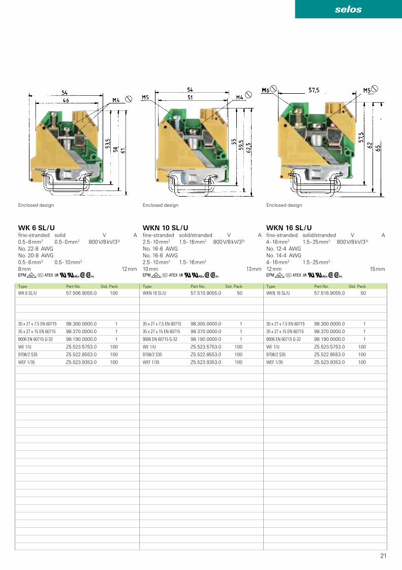
WKN 16 SL/U 57.516.9055.0 50
35 x 27 x 7,5 EN 60715 98.300.0000.0 1
35 x 27 x 15 EN 60715 98.370.0000.0 1
9006 EN 60715 G-32 98.190.0000.0 1
WE 1/U Z5.523.5753.0 100
9708/2 S35 Z5.522.8553.0 100
WEF 1/35 Z5.523.9353.0 100
WKN 10 SL/U 57.510.9055.0 50
35 x 27 x 7,5 EN 60715 98.300.0000.0 1
35 x 27 x 15 EN 60715 98.370.0000.0 1
9006 EN 60715 G-32 98.190.0000.0 1
WE 1/U Z5.523.5753.0 100
9708/2 S35 Z5.522.8553.0 100
WEF 1/35 Z5.523.9353.0 100
WK 6 SL/U 57.506.9055.0 100
35 x 27 x 7,5 EN 60715 98.300.0000.0 1
35 x 27 x 15 EN 60715 98.370.0000.0 1
9006 EN 60715 G-32 98.190.0000.0 1
WE 1/U Z5.523.5753.0 100
9708/2 S35 Z5.522.8553.0 100
WEF 1/35 Z5.523.9353.0 100
GgoC+q#wh GgoC+q#whGgoC+q#whType Part No. Std. PackType Part No. Std. PackType Part No. Std. Pack
WKN 10 SL / Ufine-stranded solid/stranded V A
2.5 - 10 mm2 1.5 - 16 mm2 800 V/8 kV/33)
No. 16-6 AWG
No. 16-6 AWG
2.5 - 10 mm2 1.5 - 16 mm2
10 mm 13 mm
WKN 16 SL / Ufine-stranded solid/stranded V A
4 - 16 mm2 1.5 - 25 mm2 800 V/8 kV/33)
No. 12-4 AWG
No. 14-4 AWG
4 - 16 mm2 1.5 - 25 mm2
12 mm 15 mm
WK 6 SL / Ufine-stranded solid V A
0.5 - 6 mm2 0.5 - 0 mm2 800 V/8 kV/33)
No. 22-8 AWG
No. 20-8 AWG
0.5 - 6 mm2 0.5 - 10 mm2
8 mm 12 mm
Enclosed design Enclosed design Enclosed design
22
selos
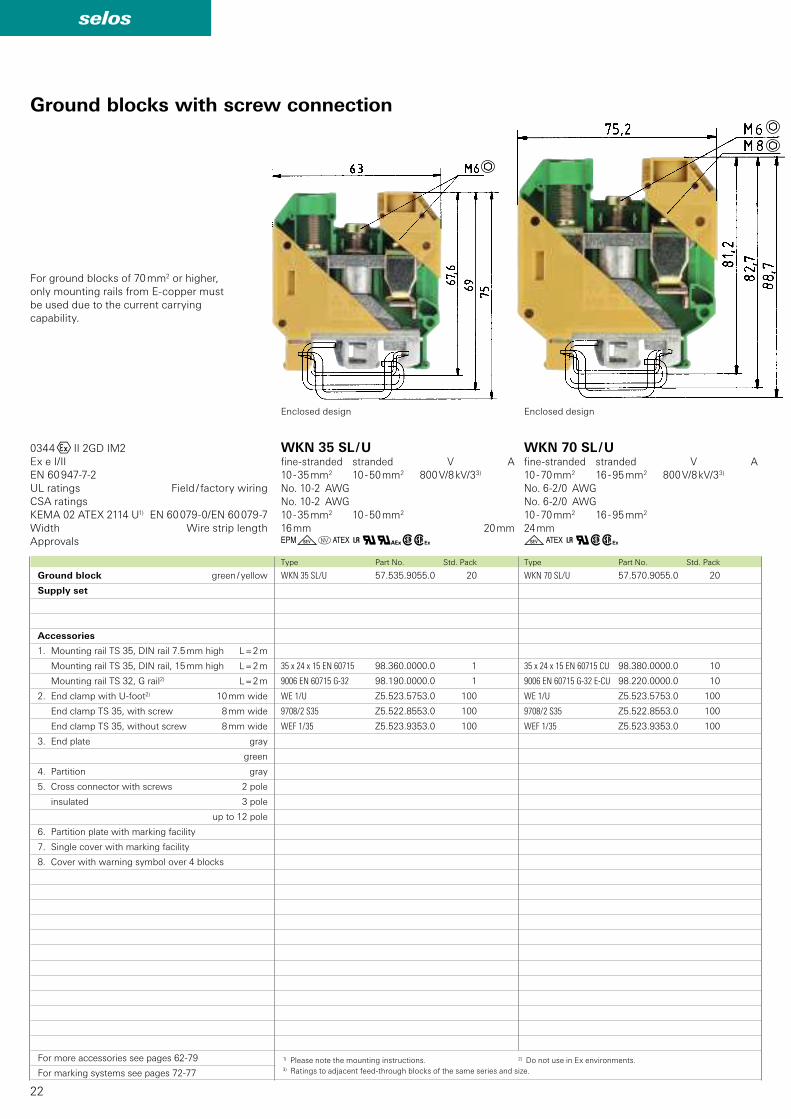
WKN 70 SL/U 57.570.9055.0 20
35 x 24 x 15 EN 60715 CU 98.380.0000.0 10
9006 EN 60715 G-32 E-CU 98.220.0000.0 10
WE 1/U Z5.523.5753.0 100
9708/2 S35 Z5.522.8553.0 100
WEF 1/35 Z5.523.9353.0 100
WKN 35 SL/U 57.535.9055.0 20
35 x 24 x 15 EN 60715 98.360.0000.0 1
9006 EN 60715 G-32 98.190.0000.0 1
WE 1/U Z5.523.5753.0 100
9708/2 S35 Z5.522.8553.0 100
WEF 1/35 Z5.523.9353.0 100
GgoC+q#wh gC+qwh
0344OII 2GD IM2
Ex e I/II
EN 60 947-7-2
KEMA 02 ATEX 2114 U1) EN 60 079-0/EN 60 079-7
Type Part No. Std. PackType Part No. Std. Pack
Ground blocks with screw connection
For ground blocks of 70 mm2 or higher,
only mounting rails from E-copper must
be used due to the current carrying
capability.
UL ratings Field / factory wiring
CSA ratings
Width Wire strip length
Approvals
WKN 35 SL / Ufine-stranded stranded V A
10 - 35 mm2 10 - 50 mm2 800 V/8 kV/33)
No. 10-2 AWG
No. 10-2 AWG
10 - 35 mm2 10 - 50 mm2
16 mm 20 mm
WKN 70 SL / Ufine-stranded stranded V A
10 - 70 mm2 16 - 95 mm2 800 V/8 kV/33)
No. 6-2/0 AWG
No. 6-2/0 AWG
10 - 70 mm2 16 - 95 mm2
24 mm
Ground block green / yellow
Supply set
Accessories
1. Mounting rail TS 35, DIN rail 7.5 mm high L = 2 m
Mounting rail TS 35, DIN rail, 15 mm high L = 2 m
Mounting rail TS 32, G rail2) L = 2 m
2. End clamp with U-foot2) 10 mm wide
End clamp TS 35, with screw 8 mm wide
End clamp TS 35, without screw 8 mm wide
3. End plate gray
green
4. Partition gray
5. Cross connector with screws 2 pole
insulated 3 pole
up to 12 pole
6. Partition plate with marking facility
7. Single cover with marking facility
8. Cover with warning symbol over 4 blocks
For more accessories see pages 62-79
For marking systems see pages 72-77
Enclosed design Enclosed design
1) Please note the mounting instructions. 2) Do not use in Ex environments.3) Ratings to adjacent feed-through blocks of the same series and size.
23
selos
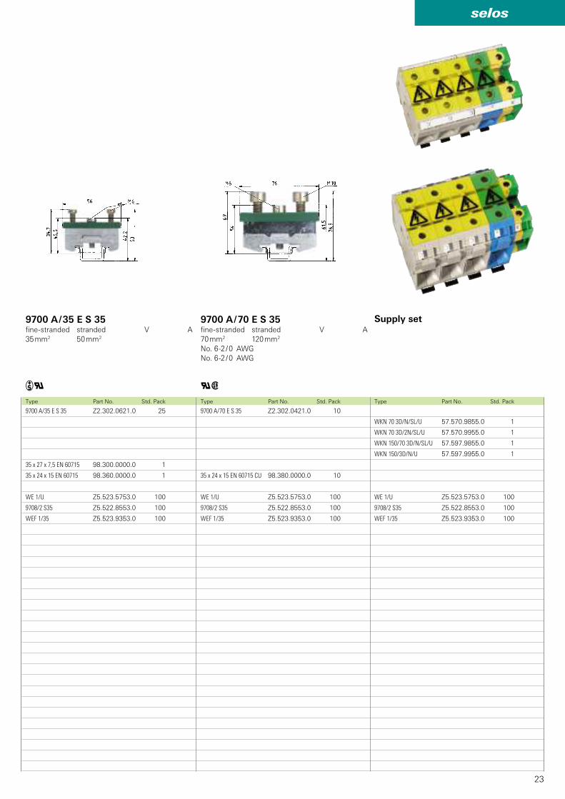
WKN 70 3D/N/SL/U 57.570.9855.0 1
WKN 70 3D/2N/SL/U 57.570.9955.0 1
WKN 150/70 3D/N/SL/U 57.597.9855.0 1
WKN 150/3D/N/U 57.597.9955.0 1
WE 1/U Z5.523.5753.0 100
9708/2 S35 Z5.522.8553.0 100
WEF 1/35 Z5.523.9353.0 100
9700 A/70 E S 35 Z2.302.0421.0 10
35 x 24 x 15 EN 60715 CU 98.380.0000.0 10
WE 1/U Z5.523.5753.0 100
9708/2 S35 Z5.522.8553.0 100
WEF 1/35 Z5.523.9353.0 100
9700 A/35 E S 35 Z2.302.0621.0 25
35 x 27 x 7,5 EN 60715 98.300.0000.0 1
35 x 24 x 15 EN 60715 98.360.0000.0 1
WE 1/U Z5.523.5753.0 100
9708/2 S35 Z5.522.8553.0 100
WEF 1/35 Z5.523.9353.0 100
qwiqType Part No. Std. PackType Part No. Std. PackType Part No. Std. Pack
9700 A / 70 E S 35fine-stranded stranded V A
70 mm2 120 mm2
No. 6-2 / 0 AWG
No. 6-2 / 0 AWG
9700 A / 35 E S 35fine-stranded stranded V A
35 mm2 50 mm2
Supply set
24
selos
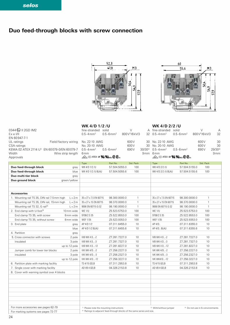
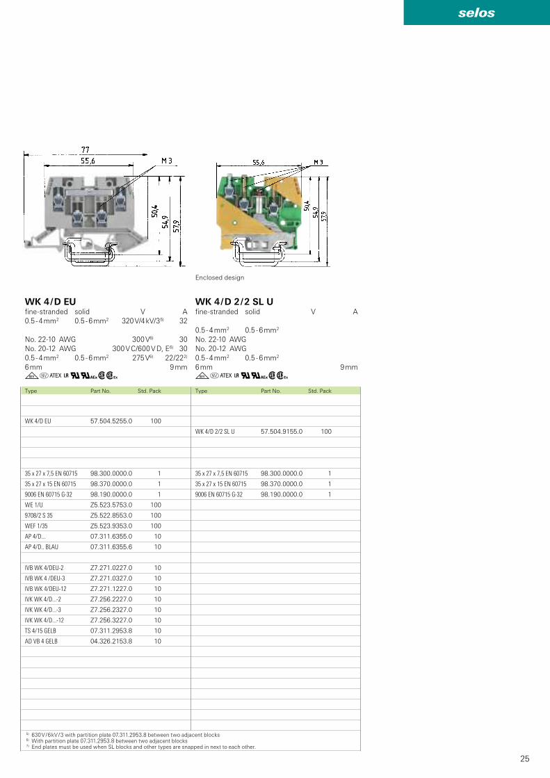
WK 4/D 2/2 /U 57.504.5155.0 100
WK 4/D 2/2 /U BLAU 57.504.5155.6 100
35 x 27 x 7,5 EN 60715 98.300.0000.0 1
35 x 27 x 15 EN 60715 98.370.0000.0 1
9006 EN 60715 G-32 98.190.0000.0 1
WE 1/U Z5.523.5753.0 100
9708/2 S 35 Z5.522.8553.0 100
WEF 1/35 Z5.523.9353.0 100
AP 4/D.. 07.311.6355.0 10
AP 4/D.. BLAU 07.311.6355.6 10
IVB WK 4 D...-2 Z7.281.7227.0 10
IVB WK 4 D...-3 Z7.281.7327.0 10
IVB WK 4 D...-12 Z7.281.8227.0 10
IVK WK 4/D...-2 Z7.256.2227.0 10
IVK WK 4/D...-3 Z7.256.2327.0 10
IVK WK4/D...-12 Z7.256.3227.0 10
TS 4/15 GELB 07.311.2953.8 10
AD VB 4 GELB 04.326.2153.8 10
WK 4/D 1/2 /U 57.504.5055.0 100
WK 4/D 1/2 /U BLAU 57.504.5055.6 100
35 x 27 x 7,5 EN 60715 98.300.0000.0 1
35 x 27 x 15 EN 60715 98.370.0000.0 1
9006 EN 60715 G-32 98.190.0000.0 1
WE 1/U Z5.523.5753.0 100
9708/2 S 35 Z5.522.8553.0 100
WEF 1/35 Z5.523.9353.0 100
AP 4/D 1/2 07.311.6455.0 10
AP 4/D 1/2 BLAU 07.311.6455.6 10
IVB WK 4 D...-2 Z7.281.7227.0 10
IVB WK 4 D...-3 Z7.281.7327.0 10
IVB WK 4 D...-12 Z7.281.8227.0 10
IVK WK 4/D...-2 Z7.256.2227.0 10
IVK WK 4/D...-3 Z7.256.2327.0 10
IVK WK 4/D...-12 Z7.256.3227.0 10
TS 4/15 GELB 07.311.2953.8 10
AD VB 4 GELB 04.326.2153.8 10
goC+q#wh goC+q#wh
0344OII 2GD IM2
Ex e I/II
EN 60 947-7-1
KEMA 02 ATEX 2114 U1) EN 60 079-0/EN 60 079-7
Type Part No. Std. PackType Part No. Std. Pack
UL ratings Field / factory wiring
CSA ratings
Width Wire strip length
Approvals
WK 4 / D 1 / 2 / Ufine-stranded solid V A
0.5 - 4 mm2 0.5 - 6 mm2 800 V7)/6 kV/3 32
No. 22-10 AWG 600 V 30
No. 20-10 AWG 600 V 30
0.5 - 4 mm2 0.5 - 6 mm2 690 V 30/302)
6 mm 9 mm
WK 4 / D 2 / 2 / Ufine-stranded solid V A
0.5 - 4 mm2 0.5 - 6 mm2 800 V7)/6 kV/3 32
No. 22-10 AWG 600 V 30
No. 20-10 AWG 600 V 30
0.5 - 4 mm2 0.5 - 6 mm2 690 V 29/302)
6 mm 9 mm
Duo feed-through blocks with screw connection
Duo feed-through block gray
Duo feed-through block blue
Duo multi-tier block gray
Duo ground block green / yellow
Accessories
1. Mounting rail TS 35, DIN rail 7.5 mm high L = 2 m
Mounting rail TS 35, DIN rail, 15 mm high L = 2 m
Mounting rail TS 32, G rail3) L = 2 m
2. End clamp with U-foot3) 10 mm wide
End clamp TS 35, with screw 8 mm wide
End clamp TS 35, without screw 8 mm wide
3. End plate gray
blue
4. Partition gray
5. Cross connector with screws 2 pole
insulated 3 pole
up to 12 pole
Jumper comb for lower tier blocks 2 pole
insulated 3 pole
up to 12 pole
6. Partition plate with marking facility
7. Single cover with marking facility
8. Cover with warning symbol over 4 blocks
For more accessories see pages 62-79
For marking systems see pages 72-77
1) Please note the mounting instructions. 2) With/without jumper 3) Do not use in Ex environments. 4) Ratings to adjacent feed-through blocks of the same series and size.
25
selos
WK 4/D 2/2 SL U 57.504.9155.0 100
35 x 27 x 7,5 EN 60715 98.300.0000.0 1
35 x 27 x 15 EN 60715 98.370.0000.0 1
9006 EN 60715 G-32 98.190.0000.0 1
WK 4/D EU 57.504.5255.0 100
35 x 27 x 7,5 EN 60715 98.300.0000.0 1
35 x 27 x 15 EN 60715 98.370.0000.0 1
9006 EN 60715 G-32 98.190.0000.0 1
WE 1/U Z5.523.5753.0 100
9708/2 S 35 Z5.522.8553.0 100
WEF 1/35 Z5.523.9353.0 100
AP 4/D... 07.311.6355.0 10
AP 4/D.. BLAU 07.311.6355.6 10
IVB WK 4/DEU-2 Z7.271.0227.0 10
IVB WK 4 /DEU-3 Z7.271.0327.0 10
IVB WK 4/DEU-12 Z7.271.1227.0 10
IVK WK 4/D...-2 Z7.256.2227.0 10
IVK WK 4/D...-3 Z7.256.2327.0 10
IVK WK 4/D...-12 Z7.256.3227.0 10
TS 4/15 GELB 07.311.2953.8 10
AD VB 4 GELB 04.326.2153.8 10
goC+q#whgoC+q#whType Part No. Std. PackType Part No. Std. Pack
WK 4 / D 2 / 2 SL Ufine-stranded solid V A
0.5 - 4 mm2 0.5 - 6 mm2
No. 22-10 AWG
No. 20-12 AWG
0.5 - 4 mm2 0.5 - 6 mm2
6 mm 9 mm
WK 4 / D EUfine-stranded solid V A
0.5 - 4 mm2 0.5 - 6 mm2 320 V/4 kV/35) 32
No. 22-10 AWG 300 V6) 30
No. 20-12 AWG 300 V C/600 V D, E6) 30
0.5 - 4 mm2 0.5 - 6 mm2 275 V6) 22/222)
6 mm 9 mm
5) 630 V / 6 kV / 3 with partition plate 07.311.2953.8 between two adjacent blocks6) With partition plate 07.311.2953.8 between two adjacent blocks7) End plates must be used when SL blocks and other types are snapped in next to each other.
Enclosed design
26
selos
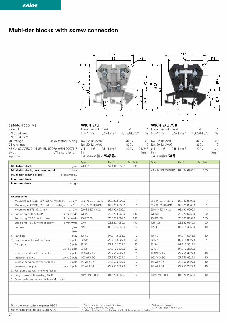
WK 4 E/U/VB SCHWARZ 57.404.6955.1 100
35 x 27 x 7,5 EN 60715 98.300.0000.0 1
35 x 27 x 15 EN 60715 98.370.0000.0 1
9006 EN 60715 G-32 98.190.0000.0 1
WE 1/U Z5.523.5753.0 100
9708/2 S 35 Z5.522.8553.0 100
WEF 1/35 Z5.523.9353.0 100
AP 4 E 07.311.4055.0 10
TW 4 E 07.311.5055.0 10
9215-2 07.210.3227.0 1
9215-3 07.210.3327.0 1
9215-6 07.210.3627.0 1
IVBS WK 4 E-2 Z7.256.4227.0 10
IVBS WK 4 E-6 Z7.256.4627.0 10
IVB WK 4 E-2 Z7.255.2227.0 10
IVB WK 4 E-6 Z7.255.2627.0 10
AD VB 4/15 GELB 04.326.2953.8 10
WK 4 E/U 57.404.7055.0 100
35 x 27 x 7,5 EN 60715 98.300.0000.0 1
35 x 27 x 15 EN 60715 98.370.0000.0 1
9006 EN 60715 G-32 98.190.0000.0 1
WE 1/U Z5.523.5753.0 100
9708/2 S 35 Z5.522.8553.0 100
9708 Z5.522.7053.0 100
AP 4 E 07.311.4055.0 10
TW 4 E 07.311.5055.0 10
9215-2 Z7.210.3227.0 50
9215-3 Z7.210.3327.0 50
9215-6 Z7.210.3627.0 50
IVBS WK 4 E-2 Z7.256.4227.0 10
IVBS WK 4 E-6 Z7.256.4627.0 10
IVB WK 4 E-2 Z7.255.2227.0 10
IVB WK 4 E-6 Z7.255.2627.0 10
AD VB 4/15 GELB 04.326.2953.8 10
goCf+qwh gof+qw
0344OII 2GD IM2
Ex e I/II
EN 60 947-7-1
EN 60 947-7-2
KEMA 02 ATEX 2114 U1) EN 60 079-0/EN 60 079-7
Type Part No. Std. PackType Part No. Std. Pack
Multi-tier blocks with screw connection
UL ratings Field / factory wiring
CSA ratings
Width Wire strip length
Approvals
WK 4 E / Ufine-stranded solid V A
0.5 - 4 mm2 0.5 - 4 mm2 400 V/6 kV/33) 32
No. 22-10 AWG 300 V 20
No. 20-12 AWG 300 V 10
0.5 - 4 mm2 0.5 - 4 mm2 275 V 24 / 242)
6 mm 9 mm
WK 4 E / U / VBfine-stranded solid V A
0.5 - 4 mm2 0.5 - 4 mm2 400 V/6 kV/3 32
No. 22-10 AWG 300 V 20
No. 20-12 AWG 300 V 10
0.5 - 4 mm2 0.5 - 4 mm2 275 V 24
6 mm 9 mm
Multi-tier block gray
Multi-tier block, vert. connected black
Multi-tier ground block green / yellow
Function block red
Function block orange
Accessories
1. Mounting rail TS 35, DIN rail 7.5 mm high L = 2 m
Mounting rail TS 35, DIN rail, 15 mm high L = 2 m
Mounting rail TS 32, G rail* L = 2 m
2. End clamp with U-foot* 10 mm wide
End clamp TS 35, with screw 8 mm wide
End clamp TS 35, without screw 8 mm wide
3. End plate gray
blue
4. Partition gray
5. Cross connector with screws 2 pole
for top tier 3 pole
up to 6 pole
Jumper comb for lower tier block 2 pole
insulated, angled up to 6 pole
Jumper comb for lower tier block 2 pole
insulated, straight up to 6 pole
6. Partition plate with marking facility
7. Single cover with marking facility
8. Cover with warning symbol over 4 blocks
For more accessories see pages 62-79
For marking systems see pages 72-77
1) Please note the mounting instructions. 2) With/without jumper3) With end plates 500 V/6 kV/3. * Do not use in Ex environments.4) Ratings to adjacent feed-through blocks of the same series and size.

27
selos
WK 4 E/U... 57.404.XX55.9 100
WK 4 E/U... 57.404.XX55.5 100
35 x 27 x 7,5 EN 60715 98.300.0000.0 1
35 x 27 x 15 EN 60715 98.370.0000.0 1
9006 EN 60715 G-32 98.190.0000.0 1
WE 1/U Z5.523.5753.0 100
9708/2 S 35 Z5.522.8553.0 100
WEF 1/35 Z5.523.9353.0 100
AP 4 E 07.311.4055.0 10
TW 4 E 07.311.5055.0 10
IVBS WK 4 E-2 Z7.256.4227.0 10
IVBS WK 4 E-6 Z7.256.4627.0 10
IVB WK 4 E-2 Z7.255.2227.0 10
IVB WK 4 E-6 Z7.255.2627.0 10
AD VB 4/15 GELB 04.326.2953.8 10
400 V
1 A/1000 V
400 V
1 A/1000 V
24 V DC
R = 4,7 K0,4 W
24 V DC
R = 4,7 K 0,4 W
1 A/400 V
42 V AC1 A/1000 VR = 6,8 K 0,6 W
24 V DC
1 AR = 4,7 K 0,4 W
57.404.8355.5
57.404.8055.9
57.404.8255.5
57.404.8155.9
57.404.7255.5
57.404.8755.5
57.404.7455.9
57.404.7955.5
57.404.8855.9
57.404.8455.5
57.404.6255.9
WK 4 E SL/U 57.504.9255.0 100
35 x 27 x 7,5 EN 60715 98.300.0000.0 1
35 x 27 x 15 EN 60715 98.370.0000.0 1
9006 EN 60715 G-32 98.190.0000.0 1
WE 1/U Z5.523.5753.0 100
9708/2 S 35 Z5.522.8553.0 100
9708 Z5.522.7053.0 100
AD VB 4/15 GELB 04.326.2953.8 10
gCqwh gof+qwType Part No. Std. PackType Part No. Std. Pack
WK 4 E SL / Ufine-stranded solid V A
0.5 - 4 mm2 0.5 - 6 mm2 500 V/6 kV/34)
No. 22-12 AWG
No. 22-10 AWG
0.5 - 4 mm2 0.5 - 6 mm2
6,2 mm 9 mm
WK 4 E / U...fine-stranded solid V A
0.5 - 4 mm2 0.5 - 4 mm2
No. 22-10 AWG
No. 20-12 AWG
6 mm 9 mm
with inverted diode
with inverted diode
LED red
LED green
LED red
with inverted diodes
The multi-tier block is available on request
as a function block for a wide variety of
switching tasks.
Examples of functions
Enclosed design
28
selos
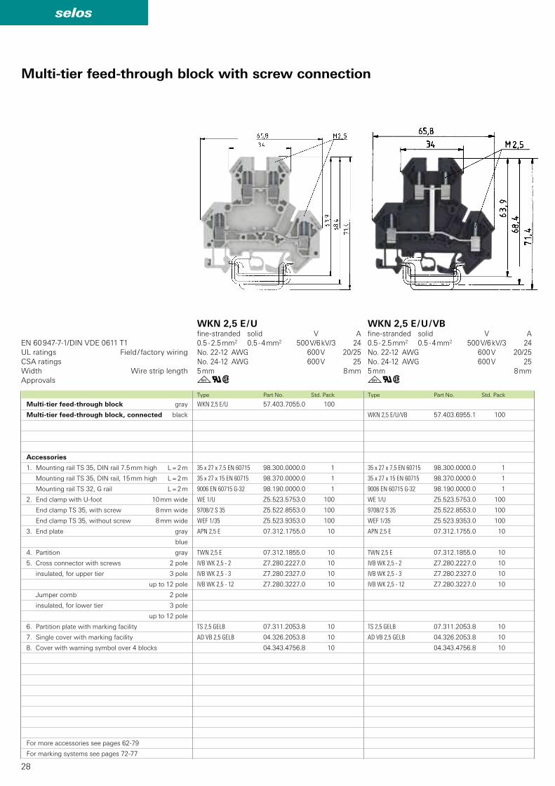
WKN 2,5 E/U/VB 57.403.6955.1 100
35 x 27 x 7,5 EN 60715 98.300.0000.0 1
35 x 27 x 15 EN 60715 98.370.0000.0 1
9006 EN 60715 G-32 98.190.0000.0 1
WE 1/U Z5.523.5753.0 100
9708/2 S 35 Z5.522.8553.0 100
WEF 1/35 Z5.523.9353.0 100
APN 2,5 E 07.312.1755.0 10
TWN 2,5 E 07.312.1855.0 10
IVB WK 2,5 - 2 Z7.280.2227.0 10
IVB WK 2,5 - 3 Z7.280.2327.0 10
IVB WK 2,5 - 12 Z7.280.3227.0 10
TS 2,5 GELB 07.311.2053.8 10
AD VB 2,5 GELB 04.326.2053.8 10
04.343.4756.8 10
WKN 2,5 E/U 57.403.7055.0 100
35 x 27 x 7,5 EN 60715 98.300.0000.0 1
35 x 27 x 15 EN 60715 98.370.0000.0 1
9006 EN 60715 G-32 98.190.0000.0 1
WE 1/U Z5.523.5753.0 100
9708/2 S 35 Z5.522.8553.0 100
WEF 1/35 Z5.523.9353.0 100
APN 2,5 E 07.312.1755.0 10
TWN 2,5 E 07.312.1855.0 10
IVB WK 2,5 - 2 Z7.280.2227.0 10
IVB WK 2,5 - 3 Z7.280.2327.0 10
IVB WK 2,5 - 12 Z7.280.3227.0 10
TS 2,5 GELB 07.311.2053.8 10
AD VB 2,5 GELB 04.326.2053.8 10
04.343.4756.8 10
gqw gqw
EN 60 947-7-1/DIN VDE 0611 T1
Type Part No. Std. PackType Part No. Std. Pack
Multi-tier feed-through block gray
Multi-tier feed-through block, connected black
Accessories
1. Mounting rail TS 35, DIN rail 7.5 mm high L = 2 m
Mounting rail TS 35, DIN rail, 15 mm high L = 2 m
Mounting rail TS 32, G rail L = 2 m
2. End clamp with U-foot 10 mm wide
End clamp TS 35, with screw 8 mm wide
End clamp TS 35, without screw 8 mm wide
3. End plate gray
blue
4. Partition gray
5. Cross connector with screws 2 pole
insulated, for upper tier 3 pole
up to 12 pole
Jumper comb 2 pole
insulated, for lower tier 3 pole
up to 12 pole
6. Partition plate with marking facility
7. Single cover with marking facility
8. Cover with warning symbol over 4 blocks
For more accessories see pages 62-79
For marking systems see pages 72-77
UL ratings Field / factory wiring
CSA ratings
Width Wire strip length
Approvals
WKN 2,5 E / Ufine-stranded solid V A
0.5 - 2.5 mm2 0.5 - 4 mm2 500 V/6 kV/3 24
No. 22-12 AWG 600 V 20/25
No. 24-12 AWG 600 V 25
5 mm 8 mm
WKN 2,5 E / U / VBfine-stranded solid V A
0.5 - 2.5 mm2 0.5 - 4 mm2 500 V/6 kV/3 24
No. 22-12 AWG 600 V 20/25
No. 24-12 AWG 600 V 25
5 mm 8 mm
Multi-tier feed-through block with screw connection

29
selos
30
selos
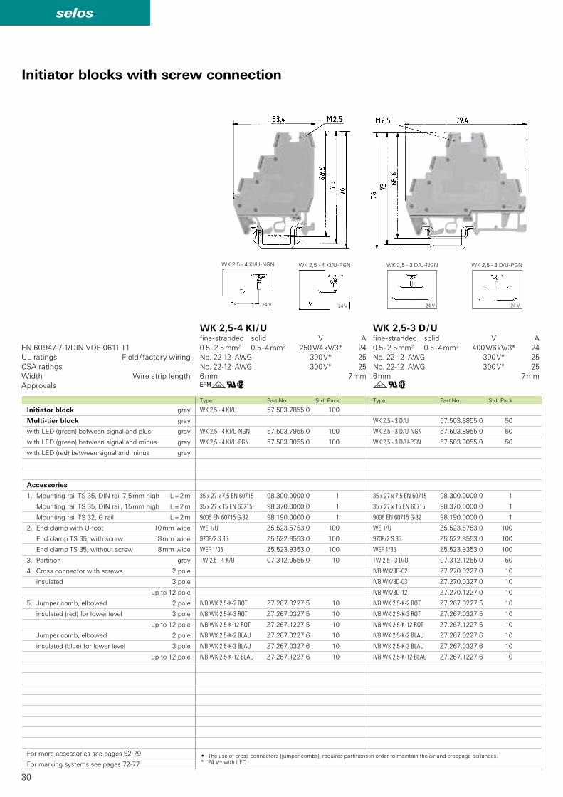
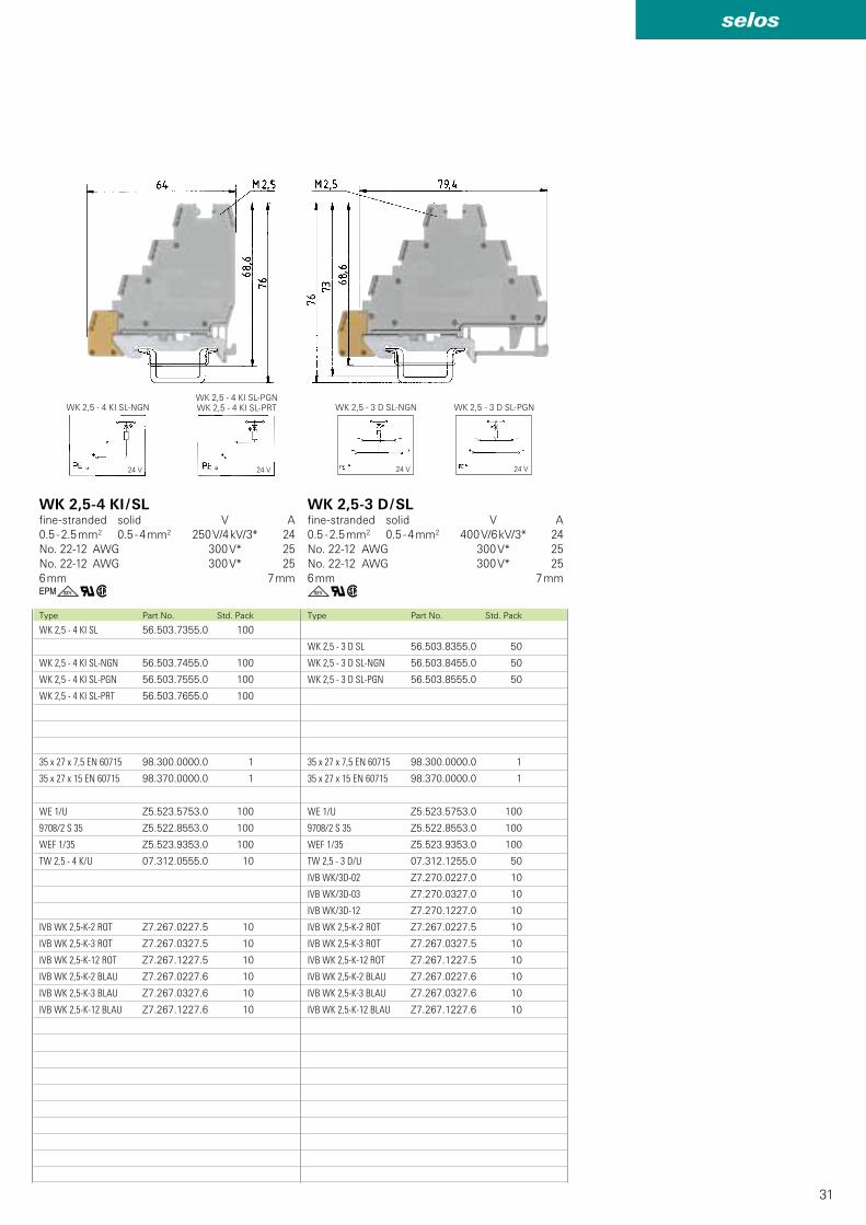
WK 2,5 - 4 KI/U-NGN
24 V
WK 2,5 - 4 KI/U-PGN
24 V
WK 2,5 - 3 D/U-NGN
24 V
WK 2,5 - 3 D/U-PGN
24 V
WK 2,5 - 3 D/U 57.503.8855.0 50
WK 2,5 - 3 D/U-NGN 57.503.8955.0 50
WK 2,5 - 3 D/U-PGN 57.503.9055.0 50
35 x 27 x 7,5 EN 60715 98.300.0000.0 1
35 x 27 x 15 EN 60715 98.370.0000.0 1
9006 EN 60715 G-32 98.190.0000.0 1
WE 1/U Z5.523.5753.0 100
9708/2 S 35 Z5.522.8553.0 100
WEF 1/35 Z5.523.9353.0 100
TW 2,5 - 3 D/U 07.312.1255.0 50
IVB WK/3D-02 Z7.270.0227.0 10
IVB WK/3D-03 Z7.270.0327.0 10
IVB WK/3D-12 Z7.270.1227.0 10
IVB WK 2,5-K-2 ROT Z7.267.0227.5 10
IVB WK 2,5-K-3 ROT Z7.267.0327.5 10
IVB WK 2,5-K-12 ROT Z7.267.1227.5 10
IVB WK 2,5-K-2 BLAU Z7.267.0227.6 10
IVB WK 2,5-K-3 BLAU Z7.267.0327.6 10
IVB WK 2,5-K-12 BLAU Z7.267.1227.6 10
WK 2,5 - 4 KI/U 57.503.7855.0 100
WK 2,5 - 4 KI/U-NGN 57.503.7955.0 100
WK 2,5 - 4 KI/U-PGN 57.503.8055.0 100
35 x 27 x 7,5 EN 60715 98.300.0000.0 1
35 x 27 x 15 EN 60715 98.370.0000.0 1
9006 EN 60715 G-32 98.190.0000.0 1
WE 1/U Z5.523.5753.0 100
9708/2 S 35 Z5.522.8553.0 100
WEF 1/35 Z5.523.9353.0 100
TW 2,5 - 4 K/U 07.312.0555.0 10
IVB WK 2,5-K-2 ROT Z7.267.0227.5 10
IVB WK 2,5-K-3 ROT Z7.267.0327.5 10
IVB WK 2,5-K-12 ROT Z7.267.1227.5 10
IVB WK 2,5-K-2 BLAU Z7.267.0227.6 10
IVB WK 2,5-K-3 BLAU Z7.267.0327.6 10
IVB WK 2,5-K-12 BLAU Z7.267.1227.6 10
Ggqw gqw
EN 60 947-7-1/DIN VDE 0611 T1
Type Part No. Std. PackType Part No. Std. Pack
Initiator blocks with screw connection
Initiator block gray
Multi-tier block gray
with LED (green) between signal and plus gray
with LED (green) between signal and minus gray
with LED (red) between signal and minus gray
Accessories
1. Mounting rail TS 35, DIN rail 7.5 mm high L = 2 m
Mounting rail TS 35, DIN rail, 15 mm high L = 2 m
Mounting rail TS 32, G rail L = 2 m
2. End clamp with U-foot 10 mm wide
End clamp TS 35, with screw 8 mm wide
End clamp TS 35, without screw 8 mm wide
3. Partition gray
4. Cross connector with screws 2 pole
insulated 3 pole
up to 12 pole
5. Jumper comb, elbowed 2 pole
insulated (red) for lower level 3 pole
up to 12 pole
Jumper comb, elbowed 2 pole
insulated (blue) for lower level 3 pole
up to 12 pole
For more accessories see pages 62-79
For marking systems see pages 72-77
UL ratings Field / factory wiring
CSA ratings
Width Wire strip length
Approvals
WK 2,5-4 KI / Ufine-stranded solid V A
0.5 - 2.5 mm2 0.5 - 4 mm2 250 V/4 kV/3* 24
No. 22-12 AWG 300 V* 25
No. 22-12 AWG 300 V* 25
6 mm 7 mm
WK 2,5-3 D / Ufine-stranded solid V A
0.5 - 2.5 mm2 0.5 - 4 mm2 400 V/6 kV/3* 24
No. 22-12 AWG 300 V* 25
No. 22-12 AWG 300 V* 25
6 mm 7 mm
• The use of cross connectors (jumper combs), requires partitions in order to maintain the air and creepage distances.* 24 Vy with LED
31
selos
WK 2,5 - 4 KI SL-NGN
24 V
WK 2,5 - 4 KI SL-PGNWK 2,5 - 4 KI SL-PRT
24 V
WK 2,5 - 3 D SL-PGN
24 V
WK 2,5 - 3 D SL-NGN
24 V
WK 2,5 - 3 D SL 56.503.8355.0 50
WK 2,5 - 3 D SL-NGN 56.503.8455.0 50
WK 2,5 - 3 D SL-PGN 56.503.8555.0 50
35 x 27 x 7,5 EN 60715 98.300.0000.0 1
35 x 27 x 15 EN 60715 98.370.0000.0 1
WE 1/U Z5.523.5753.0 100
9708/2 S 35 Z5.522.8553.0 100
WEF 1/35 Z5.523.9353.0 100
TW 2,5 - 3 D/U 07.312.1255.0 50
IVB WK/3D-02 Z7.270.0227.0 10
IVB WK/3D-03 Z7.270.0327.0 10
IVB WK/3D-12 Z7.270.1227.0 10
IVB WK 2,5-K-2 ROT Z7.267.0227.5 10
IVB WK 2,5-K-3 ROT Z7.267.0327.5 10
IVB WK 2,5-K-12 ROT Z7.267.1227.5 10
IVB WK 2,5-K-2 BLAU Z7.267.0227.6 10
IVB WK 2,5-K-3 BLAU Z7.267.0327.6 10
IVB WK 2,5-K-12 BLAU Z7.267.1227.6 10
WK 2,5 - 4 KI SL 56.503.7355.0 100
WK 2,5 - 4 KI SL-NGN 56.503.7455.0 100
WK 2,5 - 4 KI SL-PGN 56.503.7555.0 100
WK 2,5 - 4 KI SL-PRT 56.503.7655.0 100
35 x 27 x 7,5 EN 60715 98.300.0000.0 1
35 x 27 x 15 EN 60715 98.370.0000.0 1
WE 1/U Z5.523.5753.0 100
9708/2 S 35 Z5.522.8553.0 100
WEF 1/35 Z5.523.9353.0 100
TW 2,5 - 4 K/U 07.312.0555.0 10
IVB WK 2,5-K-2 ROT Z7.267.0227.5 10
IVB WK 2,5-K-3 ROT Z7.267.0327.5 10
IVB WK 2,5-K-12 ROT Z7.267.1227.5 10
IVB WK 2,5-K-2 BLAU Z7.267.0227.6 10
IVB WK 2,5-K-3 BLAU Z7.267.0327.6 10
IVB WK 2,5-K-12 BLAU Z7.267.1227.6 10
gqwGgqwType Part No. Std. PackType Part No. Std. Pack
WK 2,5-3 D / SLfine-stranded solid V A
0.5 - 2.5 mm2 0.5 - 4 mm2 400 V/6 kV/3* 24
No. 22-12 AWG 300 V* 25
No. 22-12 AWG 300 V* 25
6 mm 7 mm
WK 2,5-4 KI / SLfine-stranded solid V A
0.5 - 2.5 mm2 0.5 - 4 mm2 250 V/4 kV/3* 24
No. 22-12 AWG 300 V* 25
No. 22-12 AWG 300 V* 25
6 mm 7 mm
32
selos
WK 2,5-4 KOI/U-NGN 57.503.7155.0 50
35 x 27 x 7,5 EN 60715 98.300.0000.0 1
35 x 27 x 15 EN 60715 98.370.0000.0 1
9006 EN 60715 G-32 98.190.0000.0 1
WE 1/U Z5.523.5753.0 100
9708/2 S 35 Z5.522.8553.0 100
WEF 1/35 Z5.523.9353.0 100
AP 2,5-4 KO 07.310.9355.0 50
TW 2,5-4 KO 07.310.9455.0 50
VB WK 2,5 KO-2 07.257.0227.0 100
VB WK 2,5 KO-3 07.257.0327.0 100
VB WK 2,5 KO-20 07.257.2027.0 50
TS 2,5 GELB 07.311.2053.8 10
AD VB 2,5 GELB 04.326.2053.8 10
AD VB 5/10 04.342.0556.0 10
9705 A/5/10 B + ROT 04.855.0253.5 25
9705 A/5/10 B - BLAU 04.855.0353.6 25
WK 2,5-4 KOI/U 57.503.7055.0 50
35 x 27 x 7,5 EN 60715 98.300.0000.0 1
35 x 27 x 15 EN 60715 98.370.0000.0 1
9006 EN 60715 G-32 98.190.0000.0 1
WE 1/U Z5.523.5753.0 100
9708/2 S 35 Z5.522.8553.0 100
WEF 1/35 Z5.523.9353.0 100
AP 2,5-4 KO 07.310.9355.0 50
TW 2,5-4 KO 07.310.9455.0 50
VB WK 2,5-2 Z7.280.0227.0 10
VB WK 2,5-3 Z7.280.0327.0 10
VB WK 2,5-6 Z7.280.0627.0 10
VB WK 2,5 KO-2 07.257.0227.0 100
VB WK 2,5 KO-3 07.257.0327.0 100
VB WK 2,5 KO-20 07.257.2027.0 50
TS 2,5 GELB 07.311.2053.8 10
AD VB 2,5 GELB 04.326.2053.8 10
AD VB 5/10 04.342.0556.0 10
9705 A/5/10 B + ROT 04.855.0253.5 25
9705 A/5/10 B - BLAU 04.855.0353.6 25
gqw gqw
EN 60 947-7-1/DIN VDE 0611 T1
Type Part No. Std. PackType Part No. Std. Pack
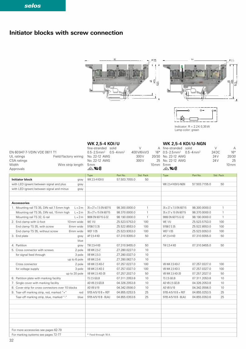
Indicator: R = 2.2 K 0,35 WLamp color: green
Initiator blocks with screw connection
Initiator block gray
with LED (green) between signal and plus gray
with LED (green) between signal and minus gray
Accessories
1. Mounting rail TS 35, DIN rail 7.5 mm high L = 2 m
Mounting rail TS 35, DIN rail, 15 mm high L = 2 m
Mounting rail TS 32, G rail L = 2 m
2. End clamp with U-foot 10 mm wide
End clamp TS 35, with screw 8 mm wide
End clamp TS 35, without screw 8 mm wide
3. End plate gray
blue
4. Partition gray
5. Cross connector with screws 2 pole
for signal feed through 3 pole
up to 6 pole
Cross connector 2 pole
for voltage supply 3 pole
up to 20 pole
6. Partition plate with marking facility
7. Single cover with marking facility
8. Cover strip for cross connectors over 10 blocks
9. Tear-off marking strip, red, marked “+” red
Tear-off marking strip, blue, marked “-” blue
For more accessories see pages 62-79
For marking systems see pages 72-77
UL ratings Field / factory wiring
CSA ratings
Width Wire strip length
Approvals
WK 2,5-4 KOI / Ufine-stranded solid V A
0.5 - 2.5 mm2 0.5 - 4 mm2 400 V/6 kV/3 16*
No. 22-12 AWG 300 V 20/30
No. 22-12 AWG 300 V 25
5 mm 10 mm
WK 2,5-4 KOI / U-NGNfine-stranded solid V A
0.5 - 2.5 mm2 0.5 - 4 mm2 24 DC 16*
No. 22-12 AWG 24 V 20/30
No. 22-12 AWG 24 V 25
5 mm 10 mm
* Feed-through 16 A
33
selos
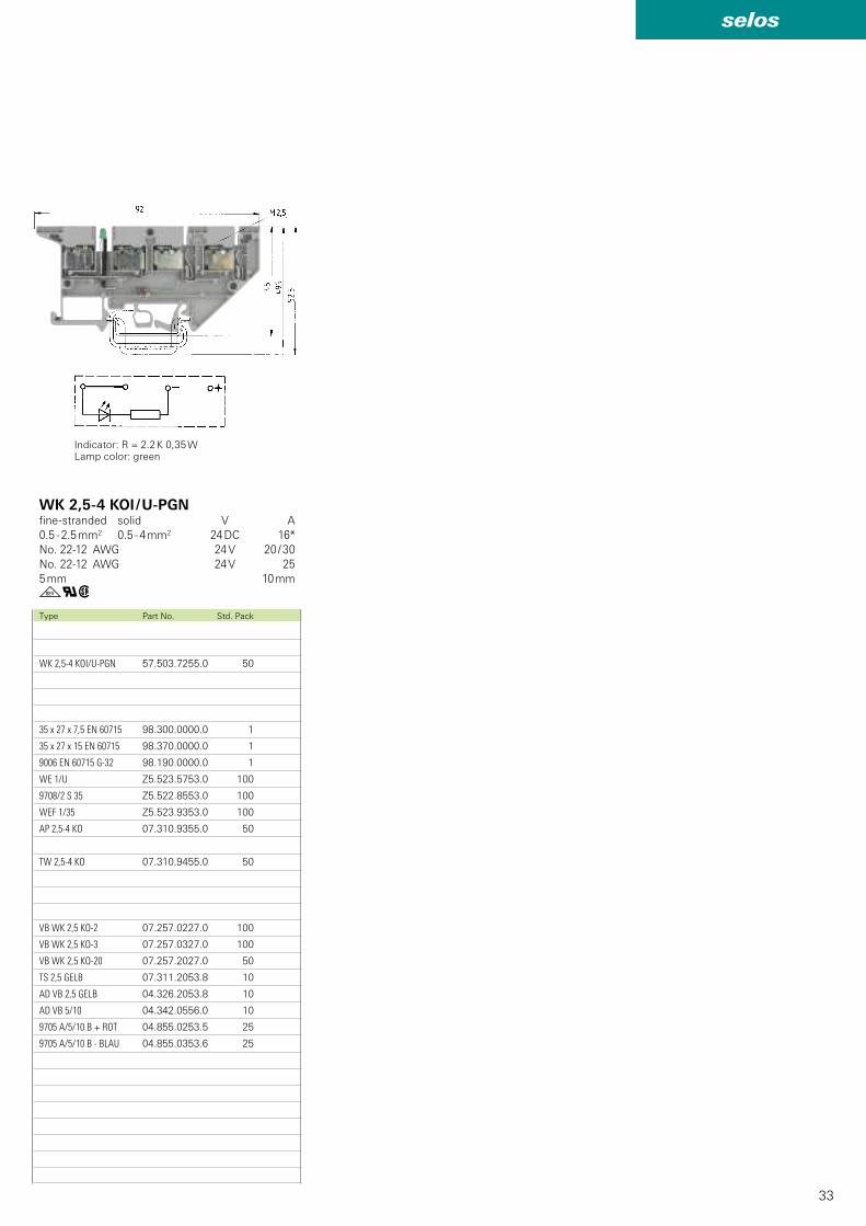
WK 2,5-4 KOI/U-PGN 57.503.7255.0 50
35 x 27 x 7,5 EN 60715 98.300.0000.0 1
35 x 27 x 15 EN 60715 98.370.0000.0 1
9006 EN 60715 G-32 98.190.0000.0 1
WE 1/U Z5.523.5753.0 100
9708/2 S 35 Z5.522.8553.0 100
WEF 1/35 Z5.523.9353.0 100
AP 2,5-4 KO 07.310.9355.0 50
TW 2,5-4 KO 07.310.9455.0 50
VB WK 2,5 KO-2 07.257.0227.0 100
VB WK 2,5 KO-3 07.257.0327.0 100
VB WK 2,5 KO-20 07.257.2027.0 50
TS 2,5 GELB 07.311.2053.8 10
AD VB 2,5 GELB 04.326.2053.8 10
AD VB 5/10 04.342.0556.0 10
9705 A/5/10 B + ROT 04.855.0253.5 25
9705 A/5/10 B - BLAU 04.855.0353.6 25
gqwType Part No. Std. Pack
Indicator: R = 2.2 K 0,35 WLamp color: green
WK 2,5-4 KOI / U-PGNfine-stranded solid V A
0.5 - 2.5 mm2 0.5 - 4 mm2 24 DC 16*
No. 22-12 AWG 24 V 20 / 30
No. 22-12 AWG 24 V 25
5 mm 10 mm
34
selos
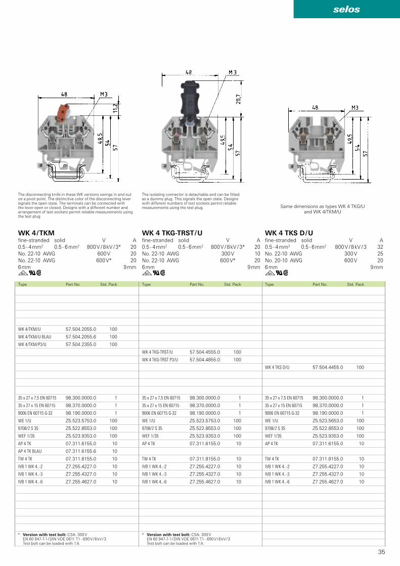
WK 4 TKG/U 57.504.4055.0 100
THSI 6,3x32 Z1.298.1653.0 10
THSI 6,3x32 LED24 Z1.298.1753.0 10
THSI 6,3x32 LED60 Z1.298.1853.0 10
THSI 6,3x32 GL250 Z1.298.1953.0 10
35 x 27 x 7,5 EN 60715 98.300.0000.0 1
35 x 27 x 15 EN 60715 98.370.0000.0 1
9006 EN 60715 G-32 98.190.0000.0 1
WE 1/U Z5.523.5753.0 100
9708/2 S 35 Z5.522.8553.0 100
WEF 1/35 Z5.523.9353.0 100
AP 4 TK 07.311.6155.0 10
TW 4 TK 07.311.8155.0 10
IVB 1 WK 4..-2 Z7.255.4227.0 10
IVB 1 WK 4..-3 Z7.255.4327.0 10
IVB 1 WK 4..-6 Z7.255.4627.0 10
WK 4 TKG/U 57.504.4055.0 100
THSI 5x20 Z1.298.1053.0 10
THSI 5x20 LED24 Z1.298.1153.0 10
THSI 5x20 LED60 Z1.298.1253.0 10
THSI 5x20 GL250 Z1.298.1353.0 10
35 x 27 x 7,5 EN 60715 98.300.0000.0 1
35 x 27 x 15 EN 60715 98.370.0000.0 1
9006 EN 60715 G-32 98.190.0000.0 1
WE 1/U Z5.523.5753.0 100
9708/2 S 35 Z5.522.8553.0 100
WEF 1/35 Z5.523.9353.0 100
AP 4 TK 07.311.6155.0 10
TW 4 TK 07.311.8155.0 10
IVB 1 WK 4..-2 Z7.255.4227.0 10
IVB 1 WK 4..-3 Z7.255.4327.0 10
IVB 1 WK 4..-6 Z7.255.4627.0 10
gqw gqw
EN 60 947-7-1/DIN VDE 0611 Teil 1
EN 60 127-6/DIN VDE 0820 T6
Type Part No. Std. PackType Part No. Std. Pack
UL ratings Field / factory wiring
CSA ratings
Width Wire strip length
Approvals
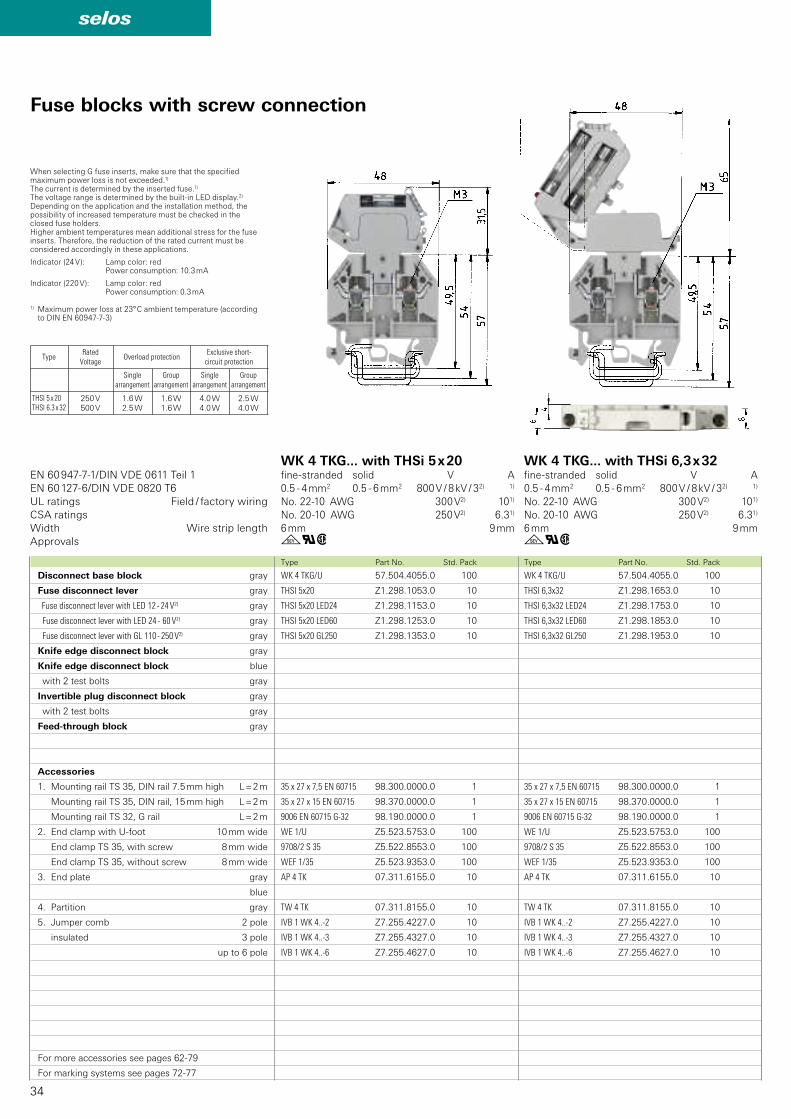
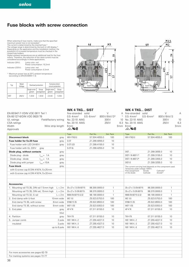
Fuse blocks with screw connection
Disconnect base block gray
Fuse disconnect lever gray
Fuse disconnect lever with LED 12 - 24 V2) gray
Fuse disconnect lever with LED 24 - 60 V2) gray
Fuse disconnect lever with GL 110 - 250 V2) gray
Knife edge disconnect block gray
Knife edge disconnect block blue
with 2 test bolts gray
Invertible plug disconnect block gray
with 2 test bolts gray
Feed-through block gray
Accessories
1. Mounting rail TS 35, DIN rail 7.5 mm high L = 2 m
Mounting rail TS 35, DIN rail, 15 mm high L = 2 m
Mounting rail TS 32, G rail L = 2 m
2. End clamp with U-foot 10 mm wide
End clamp TS 35, with screw 8 mm wide
End clamp TS 35, without screw 8 mm wide
3. End plate gray
blue
4. Partition gray
5. Jumper comb 2 pole
insulated 3 pole
up to 6 pole
For more accessories see pages 62-79
For marking systems see pages 72-77
When selecting G fuse inserts, make sure that the specified maximum power loss is not exceeded.1)
The current is determined by the inserted fuse.1) The voltage range is determined by the built-in LED display.2)
Depending on the application and the installation method, the possibility of increased temperature must be checked in the closed fuse holders.Higher ambient temperatures mean additional stress for the fuse inserts. Therefore, the reduction of the rated current must be considered accordingly in these applications.
Indicator (24 V): Lamp color: red Power consumption: 10.3 mA
Indicator (220 V): Lamp color: red Power consumption: 0.3 mA
1) Maximum power loss at 23° C ambient temperature (according to DIN EN 60947-7-3)
WK 4 TKG... with THSi 5 x 20fine-stranded solid V A
0.5 - 4 mm2 0.5 - 6 mm2 800 V / 8 kV / 32) 1)
No. 22-10 AWG 300 V2) 101)
No. 20-10 AWG 250 V2) 6.31)
6 mm 9 mm
WK 4 TKG... with THSi 6,3 x 32fine-stranded solid V A
0.5 - 4 mm2 0.5 - 6 mm2 800 V / 8 kV / 32) 1)
No. 22-10 AWG 300 V2) 101)
No. 20-10 AWG 250 V2) 6.31)
6 mm 9 mm
TypeRated
VoltageOverload protection
Exclusive short-circuit protection
Single arrangement
Group arrangement
Single arrangement
Group arrangement
THSI 5 x 20THSI 6.3 x 32
250 V
500 V
1.6 W
2.5 W
1.6 W
1.6 W
4.0 W
4.0 W
2.5 W
4.0 W
35
selos
WK 4 TKS D/U 57.504.4455.0 100
35 x 27 x 7,5 EN 60715 98.300.0000.0 1
35 x 27 x 15 EN 60715 98.370.0000.0 1
9006 EN 60715 G-32 98.190.0000.0 1
WE 1/U Z5.523.5653.0 100
9708/2 S 35 Z5.522.8553.0 100
WEF 1/35 Z5.523.9353.0 100
AP 4 TK 07.311.6155.0 10
TW 4 TK 07.311.8155.0 10
IVB 1 WK 4..-2 Z7.255.4227.0 10
IVB 1 WK 4..-3 Z7.255.4327.0 10
IVB 1 WK 4..-6 Z7.255.4627.0 10
WK 4 TKG-TRST/U 57.504.4555.0 100
WK 4 TKG-TRST P3/U 57.504.4855.0 100
35 x 27 x 7,5 EN 60715 98.300.0000.0 1
35 x 27 x 15 EN 60715 98.370.0000.0 1
9006 EN 60715 G-32 98.190.0000.0 1
WE 1/U Z5.523.5753.0 100
9708/2 S 35 Z5.522.8553.0 100
WEF 1/35 Z5.523.9353.0 100
AP 4 TK 07.311.6155.0 10
TW 4 TK 07.311.8155.0 10
IVB 1 WK 4..-2 Z7.255.4227.0 10
IVB 1 WK 4..-3 Z7.255.4327.0 10
IVB 1 WK 4..-6 Z7.255.4627.0 10
WK 4/TKM/U 57.504.2055.0 100
WK 4/TKM/U BLAU 57.504.2055.6 100
WK 4/TKM/P3/U 57.504.2355.0 100
35 x 27 x 7,5 EN 60715 98.300.0000.0 1
35 x 27 x 15 EN 60715 98.370.0000.0 1
9006 EN 60715 G-32 98.190.0000.0 1
WE 1/U Z5.523.5753.0 100
9708/2 S 35 Z5.522.8553.0 100
WEF 1/35 Z5.523.9353.0 100
AP 4 TK 07.311.6155.0 10
AP 4 TK BLAU 07.311.6155.6 10
TW 4 TK 07.311.8155.0 10
IVB 1 WK 4..-2 Z7.255.4227.0 10
IVB 1 WK 4..-3 Z7.255.4327.0 10
IVB 1 WK 4..-6 Z7.255.4627.0 10
gqw gqwgqwType Part No. Std. PackType Part No. Std. PackType Part No. Std. Pack
WK 4 TKG-TRST / Ufine-stranded solid V A
0.5 - 4 mm2 0.5 - 6 mm2 800 V / 8 kV / 3* 20
No. 22-10 AWG 300 V 10
No. 22-10 AWG 600 V* 20
6 mm 9 mm
WK 4 TKS D / Ufine-stranded solid V A
0.5 - 4 mm2 0.5 - 6 mm2 800 V / 8 kV / 3 32
No. 22-10 AWG 300 V 25
No. 20-10 AWG 600 V 20
6 mm 9 mm
WK 4 / TKMfine-stranded solid V A
0.5 - 4 mm2 0.5 - 6 mm2 800 V / 8 kV / 3* 20
No. 22-10 AWG 600 V 20
No. 22-10 AWG 600 V* 20
6 mm 9 mm
The disconnecting knife in these WK versions swings in and out on a pivot point. The distinctive color of the disconnecting lever signals the open state. The terminals can be connected with the lever open or closed. Designs with a different number and arrangement of test sockets permit reliable measurements using the test plug.
The isolating connector is detachable and can be fitted as a dummy plug. This signals the open state. Designs with different numbers of test sockets permit reliable measurements using the test plug. Same dimensions as types WK 4 TKG/U
and WK 4/TKM/U
* Version with test bolt: CSA: 300 V EN 60 947-7-1 / DIN VDE 0611 T1 – 690 V / 6 kV / 3 Test bolt can be loaded with 1 A
* Version with test bolt: CSA: 300 V EN 60 947-7-1 / DIN VDE 0611 T1 – 690 V / 6 kV / 3 Test bolt can be loaded with 1 A
36
selos
WK 4 TKG/U 57.504.4055.0 100
DIST ... Z1.299.3055.0 10
DIST-1 N 4007-13) Z1.299.3155.0 10
DIST-1 N 4007-24) Z1.299.3355.0 10
DIST-D Z1.299.3255.0 10
35 x 27 x 7,5 EN 60715 98.300.0000.0 1
35 x 27 x 15 EN 60715 98.370.0000.0 1
9006 EN 60715 G-32 98.190.0000.0 1
WE 1/U Z5.523.5753.0 100
9708/2 S 35 Z5.522.8553.0 100
WEF 1/35 Z5.523.9353.0 100
AP 4 TK 07.311.6155.0 10
TW 4 TK 07.311.8155.0 10
IVB 1 WK 4..-2 Z7.255.4227.0 10
IVB 1 WK 4..-3 Z7.255.4327.0 10
IVB 1 WK 4..-6 Z7.255.4627.0 10
WK 4 TKG/U 57.504.4055.0 100
Si ST Z1.299.4055.0 10
Si ST LED Z1.299.4155.0 10
Si ST GL Z1.299.4255.0 10
35 x 27 x 7,5 EN 60715 98.300.0000.0 1
35 x 27 x 15 EN 60715 98.370.0000.0 1
9006 EN 60715 G-32 98.190.0000.0 1
WE 1/U Z5.523.5753.0 100
9708/2 S 35 Z5.522.8553.0 100
WEF 1/35 Z5.523.9353.0 100
AP 4 TK 07.311.6155.0 10
TW 4 TK 07.311.8155.0 10
IVB 1 WK 4..-2 Z7.255.4227.0 10
IVB 1 WK 4..-3 Z7.255.4327.0 10
IVB 1 WK 4..-6 Z7.255.4627.0 10
gqw gqw
EN 60 947-7-1/DIN VDE 0611 Teil 1
EN 60 127-6/DIN VDE 0820 T6
Type Part No. Std. PackType Part No. Std. Pack
UL ratings Field/factory wiring
CSA ratings
Width Wire strip length
Approvals
Fuse blocks with screw connection
Disconnect block gray
Fuse holder for 5 x 20 fuse gray
Fuse holder with LED 24-60 V gray
Fuse holder with GL 220 V gray
Diode plug, without contacts gray
Diode plug - diode Imax
= 1 A gray
Diode plug - diode Imax
= 1 A gray
Diode plug with jumper Imax
= 10 A gray
Fuse block gray
with G-screw cap B DIN 41674, 5 x 25 mm
with G-screw cap A DIN 41674, 5 x 20 mm
Accessories
1. Mounting rail TS 35, DIN rail 7.5 mm high L = 2 m
Mounting rail TS 35, DIN rail, 15 mm high L = 2 m
Mounting rail TS 32, G rail L = 2 m
2. End clamp with U-foot 10 mm wide
End clamp TS 35, with screw 8 mm wide
End clamp TS 35, without screw 8 mm wide
3. End plate gray
blue
4. Partition gray
5. Jumper comb 2 pole
insulated 3 pole
up to 6 pole
For more accessories see pages 62-79
For marking systems see pages 72-77
WK 4 TKG... SISTfine-stranded solid V A
0.5 - 4 mm2 0.5 - 6 mm2 800 V / 8 kV / 32) 1)
No. 22-10 AWG 300 V 10
No. 20-10 AWG 250 V 6.3
6 mm 9 mm
WK 4 TKG... DISTfine-stranded solid V A
0.5 - 4 mm2 0.5 - 6 mm2 800 V / 8 kV / 3
No. 22-10 AWG 300 V 10
No. 20-10 AWG 250 V 6,3
6 mm 9 mm
When selecting G fuse inserts, make sure that the specified maximum power loss is not exceeded.1)
The current is determined by the inserted fuse.1) The voltage range is determined by the built-in LED display.2)
Depending on the application and the installation method, the possibility of increased temperature must be checked in the closed fuse holders.Higher ambient temperatures are an additional load for the fuse inserts. Therefore, the reduction of the rated current must be considered accordingly in these applications.
Indicator (24 V): Lamp color: red Power consumption: 10,3 mA
Indicator (220 V): Lamp color: red Power consumption: 0.3 mA
1) Maximum power loss at 23° C ambient temperature (according to DIN EN 60947-7-3)
The current carrying load depends on the component used. Temporary peak voltage 1000 V.Pole assignment Anode Cathode3)
of the diode: Cathode Anode4)
TypRated
VoltageOverload protection
Exclusive short-circuit protection
Single arran-gement
Group arrangement
Single arran-gement
Group arrangement
SIST 250 V 1.6 W 1.6 W 2.5 W 1.6 W
37
selos
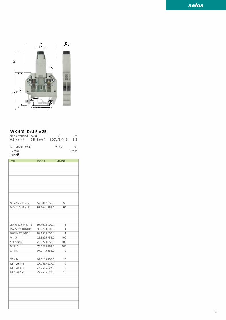
WK 4/Si-D/U 5 x 25 57.504.1655.0 50
WK 4/Si-D/U 5 x 20 57.504.1755.0 50
35 x 27 x 7,5 EN 60715 98.300.0000.0 1
35 x 27 x 15 EN 60715 98.370.0000.0 1
9006 EN 60715 G-32 98.190.0000.0 1
WE 1/U Z5.523.5753.0 100
9708/2 S 35 Z5.522.8553.0 100
WEF 1/35 Z5.523.9353.0 100
AP 4 TK 07.311.6155.0 10
TW 4 TK 07.311.8155.0 10
IVB 1 WK 4..-2 Z7.255.4227.0 10
IVB 1 WK 4..-3 Z7.255.4327.0 10
IVB 1 WK 4..-6 Z7.255.4627.0 10
gwType Part No. Std. Pack
WK 4 / Si-D / U 5 x 25fine-stranded solid V A
0.5 - 4 mm2 0.5 - 6 mm2 800 V / 8 kV / 3 6,3
No. 20-10 AWG 250 V 10
12 mm 9 mm
38
selos
WK 4/THSi 6,3 ... U 57.904.6355.0 50
WK 4/THSi 6,3 LED 12 U 57.904.6455.0 50
WK 4/THSi 6,3 LED 24 U 57.904.6555.0 50
WK 4/THSi 6,3 LED 60 U 57.904.6655.0 50
WK 4/THSi 6,3 GL 250 U 57.904.6755.0 50
WK 4/THSi 6,3 GL 500 U 57.904.6855.0 50
35 x 27 x 7,5 EN 60715 98.300.0000.0 1
35 x 27 x 15 EN 60715 98.370.0000.0 1
9006 EN 60715 G-32 98.190.0000.0 1
WE 1/U Z5.523.5753.0 100
9708/2 S 35 Z5.522.8553.0 100
WEF 1/35 Z5.523.9353.0 100
WK 4/THSi 5 ... U 57.904.5355.0 50
WK 4/THSi 5 LED 12 U 57.904.5455.0 50
WK 4/THSi 5 LED 24 U 57.904.5555.0 50
WK 4/THSi 5 LED 60 U 57.904.5655.0 50
WK 4/THSi 5 GL 250 U 57.904.5755.0 50
WK 4/THSi 5 GL 500 U 57.904.5855.0 50
35 x 27 x 7,5 EN 60715 98.300.0000.0 1
35 x 27 x15 EN 60715 98.370.0000.0 1
9006 EN 60715 G-32 98.190.0000.0 1
WE 1/U Z5.523.5753.0 100
9708/2 S 35 Z5.522.8553.0 100
WEF 1/35 Z5.523.9353.0 100
gqw gqw
EN 60 947-7-1, EN 60 127-6
Type Part No. Std. PackType Part No. Std. Pack
UL ratings Field / factory wiring
CSA ratings
Width Wire strip length
Approvals
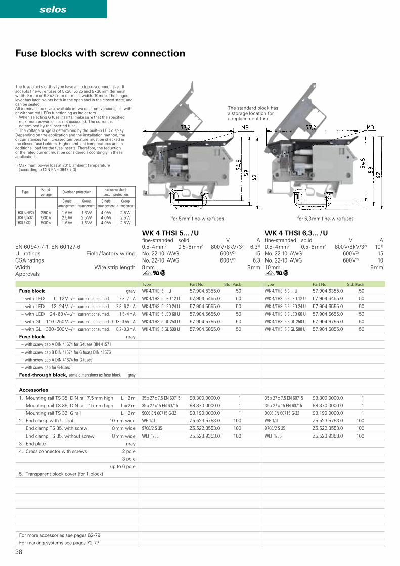
Fuse blocks with screw connection
Fuse block gray
– with LED 5 - 12 V~/y current consumed. 2.3 - 7 mA
– with LED 12 - 24 V~/y current consumed. 2.8 - 6,2 mA
– with LED 24 - 60 V~,/y current consumed. 1.5 - 4 mA
– with GL 110 - 250 V~/y current consumed. 0.13 - 0.55 mA
– with GL 380 - 500 V~/y current consumed. 0.2 - 0.3 mA
Fuse block gray
– with screw cap A DIN 41674 for G-fuses DIN 41571
– with screw cap B DIN 41674 for G fuses DIN 41576
– with screw cap A DIN 41674 for G-fuses
– with screw cap for G-fuses
Feed-through block, same dimensions as fuse block gray
Accessories
1. Mounting rail TS 35, DIN rail 7.5 mm high L = 2 m
Mounting rail TS 35, DIN rail, 15 mm high L = 2 m
Mounting rail TS 32, G rail L = 2 m
2. End clamp with U-foot 10 mm wide
End clamp TS 35, with screw 8 mm wide
End clamp TS 35, without screw 8 mm wide
3. End plate gray
4. Cross connector with screws 2 pole
3 pole
up to 6 pole
5. Transparent block cover (for 1 block)
For more accessories see pages 62-79
For marking systems see pages 72-77
WK 4 THSI 5... / Ufine-stranded solid V A
0.5 - 4 mm2 0.5 - 6 mm2 800 V / 8 kV / 32) 6.31)
No. 22-10 AWG 600 V2) 15
No. 22-10 AWG 600 V2) 6.3
8 mm 8 mm
WK 4 THSI 6,3... / Ufine-stranded solid V A
0.5 - 4 mm2 0.5 - 6 mm2 800 V / 8 kV / 32) 101)
No. 22-10 AWG 600 V2) 15
No. 22-10 AWG 600 V2) 10
10 mm 8 mm
The fuse blocks of this type have a flip top disconnect lever. It accepts fine-wire fuses of 5 x 20, 5 x 25 and 5 x 30 mm (terminal width: 8 mm) or 6.3 x 32 mm (terminal width: 10 mm). The hinged lever has latch points both in the open and in the closed state, and can be sealed.All terminal blocks are available in two different versions, i.e. with or without red LEDs functioning as indicators.1) When selecting G fuse inserts, make sure that the specified
maximum power loss is not exceeded. The current is determined by the inserted fuse.
2) The voltage range is determined by the built-in LED display.Depending on the application and the installation method, the circumstances for increased temperature must be checked in the closed fuse holders. Higher ambient temperatures are an additional load for the fuse inserts. Therefore, the reduction of the rated current must be considered accordingly in these applications.
1) Maximum power loss at 23° C ambient temperature (according to DIN EN 60947-7-3)
for 5 mm fine-wire fuses
The standard block has a storage location for a replacement fuse.
for 6,3 mm fine-wire fuses
TypeRated-voltage
Overload protectionExclusive short-
circuit protection
Single arrangement
Group arrangement
Single arrangement
Group arrangement
THSI 5 x 20 / 25THSI 6,3 x 32THSI 5 x 30
250 V
500 V
500 V
1.6 W
2.5 W
1.6 W
1.6 W
2.5 W
1.6 W
4.0 W
4.0 W
4.0 W
2.5 W
2.5 W
2.5 W
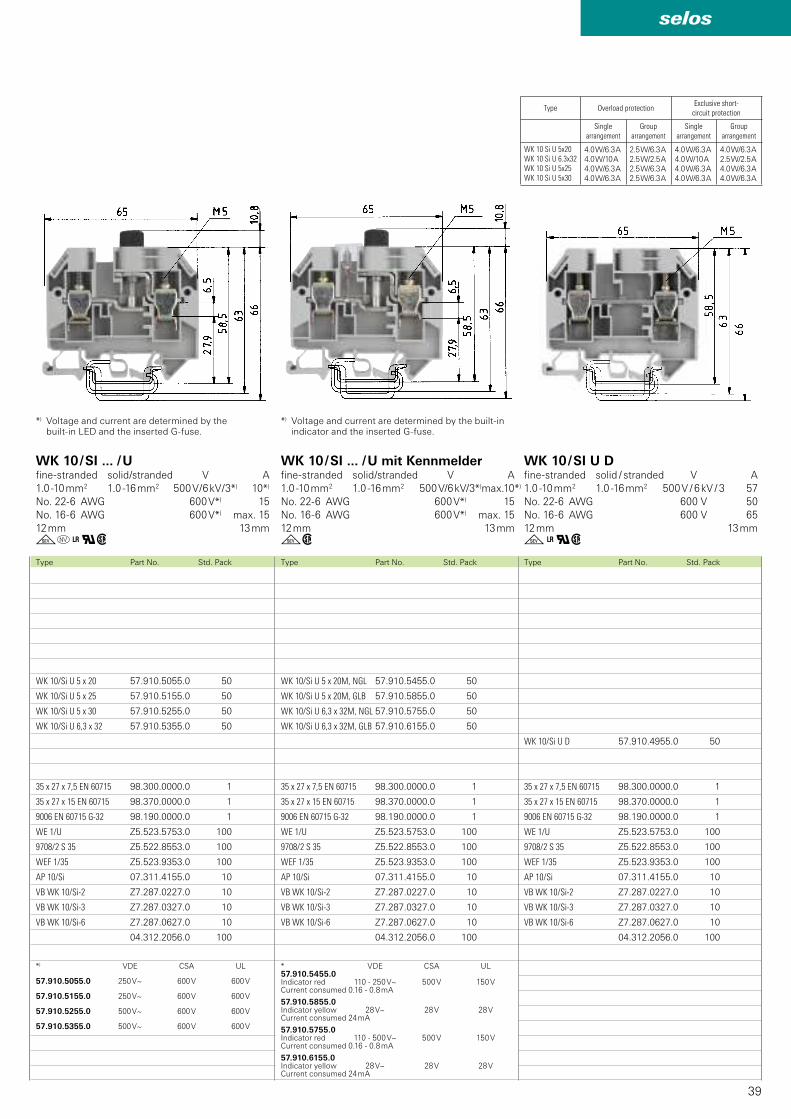
39
selos
WK 10/Si U D 57.910.4955.0 50
35 x 27 x 7,5 EN 60715 98.300.0000.0 1
35 x 27 x 15 EN 60715 98.370.0000.0 1
9006 EN 60715 G-32 98.190.0000.0 1
WE 1/U Z5.523.5753.0 100
9708/2 S 35 Z5.522.8553.0 100
WEF 1/35 Z5.523.9353.0 100
AP 10/Si 07.311.4155.0 10
VB WK 10/Si-2 Z7.287.0227.0 10
VB WK 10/Si-3 Z7.287.0327.0 10
VB WK 10/Si-6 Z7.287.0627.0 10
04.312.2056.0 100
WK 10/Si U 5 x 20M, NGL 57.910.5455.0 50
WK 10/Si U 5 x 20M, GLB 57.910.5855.0 50
WK 10/Si U 6,3 x 32M, NGL 57.910.5755.0 50
WK 10/Si U 6,3 x 32M, GLB 57.910.6155.0 50
35 x 27 x 7,5 EN 60715 98.300.0000.0 1
35 x 27 x 15 EN 60715 98.370.0000.0 1
9006 EN 60715 G-32 98.190.0000.0 1
WE 1/U Z5.523.5753.0 100
9708/2 S 35 Z5.522.8553.0 100
WEF 1/35 Z5.523.9353.0 100
AP 10/Si 07.311.4155.0 10
VB WK 10/Si-2 Z7.287.0227.0 10
VB WK 10/Si-3 Z7.287.0327.0 10
VB WK 10/Si-6 Z7.287.0627.0 10
04.312.2056.0 100
WK 10/Si U 5 x 20 57.910.5055.0 50
WK 10/Si U 5 x 25 57.910.5155.0 50
WK 10/Si U 5 x 30 57.910.5255.0 50
WK 10/Si U 6,3 x 32 57.910.5355.0 50
35 x 27 x 7,5 EN 60715 98.300.0000.0 1
35 x 27 x 15 EN 60715 98.370.0000.0 1
9006 EN 60715 G-32 98.190.0000.0 1
WE 1/U Z5.523.5753.0 100
9708/2 S 35 Z5.522.8553.0 100
WEF 1/35 Z5.523.9353.0 100
AP 10/Si 07.311.4155.0 10
VB WK 10/Si-2 Z7.287.0227.0 10
VB WK 10/Si-3 Z7.287.0327.0 10
VB WK 10/Si-6 Z7.287.0627.0 10
04.312.2056.0 100
* VDE CSA UL57.910.5455.0 110 - 250 V~ 500 V 150 V
57.910.5855.0 28 V~ 28 V 28 V
57.910.5755.0 110 - 500 V~ 500 V 150 V
57.910.6155.0 28 V~ 28 V 28 V
*) VDE CSA UL
57.910.5055.0 250 V~ 600 V 600 V
57.910.5155.0 250 V~ 600 V 600 V
57.910.5255.0 500 V~ 600 V 600 V
57.910.5355.0 500 V~ 600 V 600 V
gw g+qwgo+qw
Type Part No. Std. PackType Part No. Std. PackType Part No. Std. Pack
WK 10 / SI ... / U mit Kennmelderfine-stranded solid/stranded V A
1.0 -10 mm2 1.0 -16 mm2 500 V/6 kV/3*) max.10*)
No. 22-6 AWG 600 V*) 15
No. 16-6 AWG 600 V*) max. 15
12 mm 13 mm
WK 10 / SI U Dfine-stranded solid / stranded V A
1.0 -10 mm2 1.0 -16 mm2 500 V / 6 kV / 3 57
No. 22-6 AWG 600 V 50
No. 16-6 AWG 600 V 65
12 mm 13 mm
WK 10 / SI ... / Ufine-stranded solid/stranded V A
1.0 -10 mm2 1.0 -16 mm2 500 V / 6 kV / 3*) 10*)
No. 22-6 AWG 600 V*) 15
No. 16-6 AWG 600 V*) max. 15
12 mm 13 mm
*) Voltage and current are determined by the built-in LED and the inserted G-fuse.
*) Voltage and current are determined by the built-in indicator and the inserted G-fuse.
Indicator redCurrent consumed 0.16 - 0.8 mA
Indicator yellowCurrent consumed 24 mA
Indicator redCurrent consumed 0.16 - 0.8 mA
Indicator yellowCurrent consumed 24 mA
Type Overload protectionExclusive short-
circuit protection
Single arrangement
Group arrangement
Single arrangement
Group arrangement
WK 10 Si U 5x20WK 10 Si U 6.3x32WK 10 Si U 5x25WK 10 Si U 5x30
4.0 W/6.3 A
4.0 W/10 A
4.0 W/6.3 A
4.0 W/6.3 A
2.5 W/6.3 A
2.5 W/2.5 A
2.5 W/6.3 A
2.5 W/6.3 A
4.0 W/6.3 A
4.0 W/10 A
4.0 W/6.3 A
4.0 W/6.3 A
4.0 W/6.3 A
2.5 W/2.5 A
4.0 W/6.3 A
4.0 W/6.3 A
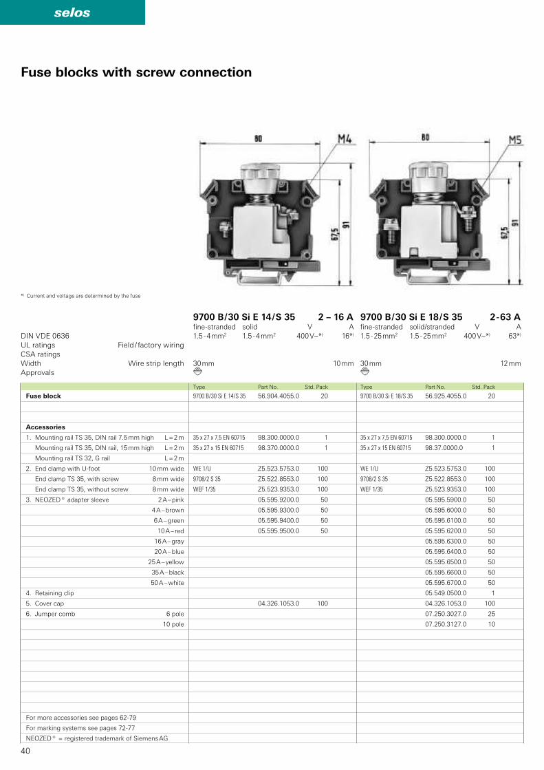
40
selos
9700 B/30 Si E 18/S 35 56.925.4055.0 20
35 x 27 x 7,5 EN 60715 98.300.0000.0 1
35 x 27 x 15 EN 60715 98.37.0000.0 1
WE 1/U Z5.523.5753.0 100
9708/2 S 35 Z5.522.8553.0 100
WEF 1/35 Z5.523.9353.0 100
05.595.5900.0 50
05.595.6000.0 50
05.595.6100.0 50
05.595.6200.0 50
05.595.6300.0 50
05.595.6400.0 50
05.595.6500.0 50
05.595.6600.0 50
05.595.6700.0 50
05.549.0500.0 1
04.326.1053.0 100
07.250.3027.0 25
07.250.3127.0 10
9700 B/30 Si E 14/S 35 56.904.4055.0 20
35 x 27 x 7,5 EN 60715 98.300.0000.0 1
35 x 27 x 15 EN 60715 98.370.0000.0 1
WE 1/U Z5.523.5753.0 100
9708/2 S 35 Z5.522.8553.0 100
WEF 1/35 Z5.523.9353.0 100
05.595.9200.0 50
05.595.9300.0 50
05.595.9400.0 50
05.595.9500.0 50
04.326.1053.0 100
d d
DIN VDE 0636
Type Part No. Std. PackType Part No. Std. Pack
UL ratings Field / factory wiring
CSA ratings
Width Wire strip length
Approvals
Fuse blocks with screw connection
9700 B / 30 Si E 14 / S 35 2 – 16 Afine-stranded solid V A
1.5 - 4 mm2 1.5 - 4 mm2 400 V~*) 16*)
30 mm 10 mm
9700 B / 30 Si E 18 / S 35 2 - 63 Afine-stranded solid/stranded V A
1.5 - 25 mm2 1.5 - 25 mm2 400 V~*) 63*)
30 mm 12 mm
Fuse block
Accessories
1. Mounting rail TS 35, DIN rail 7.5 mm high L = 2 m
Mounting rail TS 35, DIN rail, 15 mm high L = 2 m
Mounting rail TS 32, G rail L = 2 m
2. End clamp with U-foot 10 mm wide
End clamp TS 35, with screw 8 mm wide
End clamp TS 35, without screw 8 mm wide
3. NEOZED® adapter sleeve 2 A – pink
4 A – brown
6 A – green
10 A – red
16 A – gray
20 A – blue
25 A – yellow
35 A – black
50 A – white
4. Retaining clip
5. Cover cap
6. Jumper comb 6 pole
10 pole
For more accessories see pages 62-79
For marking systems see pages 72-77
NEOZED® = registered trademark of Siemens AG
*) Current and voltage are determined by the fuse

41
selos
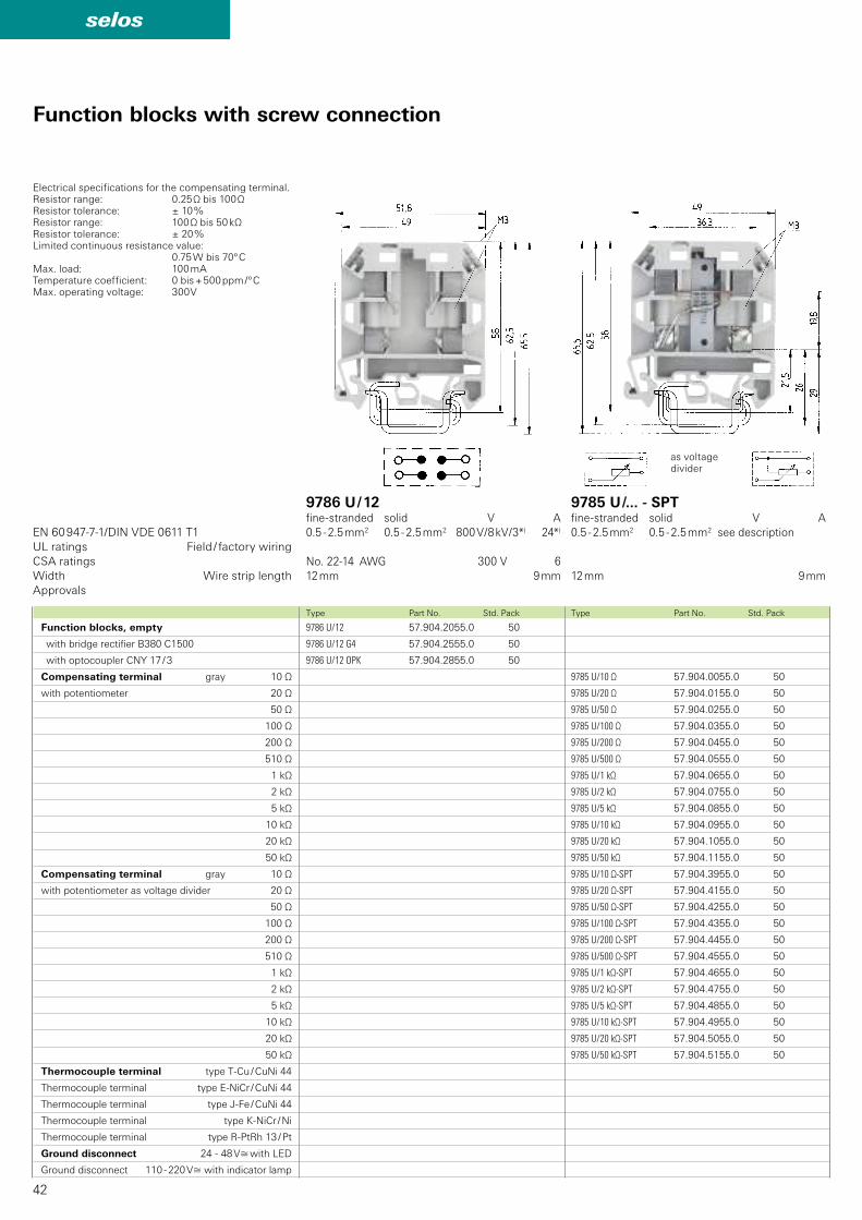
42
selos
9785 U/10 Ω 57.904.0055.0 50
9785 U/20 Ω 57.904.0155.0 50
9785 U/50 Ω 57.904.0255.0 50
9785 U/100 Ω 57.904.0355.0 50
9785 U/200 Ω 57.904.0455.0 50
9785 U/500 Ω 57.904.0555.0 50
9785 U/1 kΩ 57.904.0655.0 50
9785 U/2 kΩ 57.904.0755.0 50
9785 U/5 kΩ 57.904.0855.0 50
9785 U/10 kΩ 57.904.0955.0 50
9785 U/20 kΩ 57.904.1055.0 50
9785 U/50 kΩ 57.904.1155.0 50
9785 U/10 Ω-SPT 57.904.3955.0 50
9785 U/20 Ω-SPT 57.904.4155.0 50
9785 U/50 Ω-SPT 57.904.4255.0 50
9785 U/100 Ω-SPT 57.904.4355.0 50
9785 U/200 Ω-SPT 57.904.4455.0 50
9785 U/500 Ω-SPT 57.904.4555.0 50
9785 U/1 kΩ-SPT 57.904.4655.0 50
9785 U/2 kΩ-SPT 57.904.4755.0 50
9785 U/5 kΩ-SPT 57.904.4855.0 50
9785 U/10 kΩ-SPT 57.904.4955.0 50
9785 U/20 kΩ-SPT 57.904.5055.0 50
9785 U/50 kΩ-SPT 57.904.5155.0 50
9786 U/12 57.904.2055.0 50
9786 U/12 G4 57.904.2555.0 50
9786 U/12 OPK 57.904.2855.0 50
EN 60 947-7-1/DIN VDE 0611 T1
Type Part No. Std. PackType Part No. Std. Pack
UL ratings Field / factory wiring
CSA ratings
Width Wire strip length
Approvals
Function blocks with screw connection
Function blocks, empty
with bridge rectifier B380 C1500
with optocoupler CNY 17 / 3
Compensating terminal gray 10 Ω
with potentiometer 20 Ω
50 Ω
100 Ω
200 Ω
510 Ω
1 kΩ
2 kΩ
5 kΩ
10 kΩ
20 kΩ
50 kΩ
Compensating terminal gray 10 Ω
with potentiometer as voltage divider 20 Ω
50 Ω
100 Ω
200 Ω
510 Ω
1 kΩ
2 kΩ
5 kΩ
10 kΩ
20 kΩ
50 kΩ
Thermocouple terminal type T-Cu / CuNi 44
Thermocouple terminal type E-NiCr / CuNi 44
Thermocouple terminal type J-Fe / CuNi 44
Thermocouple terminal type K-NiCr / Ni
Thermocouple terminal type R-PtRh 13 / Pt
Ground disconnect 24 - 48 Vù with LED
Ground disconnect 110 - 220 Vù with indicator lamp
9786 U / 12fine-stranded solid V A
0.5 - 2.5 mm2 0.5 - 2.5 mm2 800 V / 8 kV / 3*) 24*)
No. 22-14 AWG 300 V 6
12 mm 9 mm
9785 U /... - SPTfine-stranded solid V A
0.5 - 2.5 mm2 0.5 - 2.5 mm2 see description
12 mm 9 mm
as voltage divider
Electrical specifications for the compensating terminal.Resistor range: 0.25 Ω bis 100 ΩResistor tolerance: ± 10 %Resistor range: 100 Ω bis 50 kΩResistor tolerance: ± 20 %Limited continuous resistance value: 0.75 W bis 70º CMax. load: 100 mATemperature coefficient: 0 bis + 500 ppm /º CMax. operating voltage: 300 V
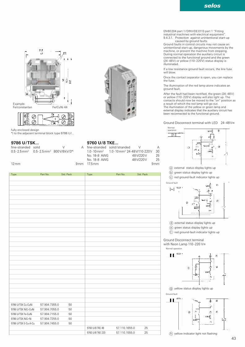
43
selos
9760 U/8 TKE 48 57.110.1655.0 25
9760 U/8 TKE 220 57.110.1555.0 25
9786 U/TSK Cu-CuNi 57.904.7355.0 50
9786 U/TSK NiCr-CuNi 57.904.7055.0 50
9786 U/TSK Fe-CuNi 57.904.7155.0 50
9786 U/TSK NiCr-Ni 57.904.7255.0 50
9786 U/TSK E-Cu-A-Cu 57.904.7455.0 50
Type Part No. Std. PackType Part No. Std. Pack
9760 U / 8 TKE...fine-stranded solid / stranded V A
1.0 - 10 mm2 1.0 - 10 mm2 24-48 V/110-220 V 30
No. 18-8 AWG 48 V/220 V 25
No. 18-8 AWG 48 V/220 V 25
17.5 mm 9 mm
9786 U / TSK...fine-stranded solid V A
0.5 - 2.5 mm2 0.5 - 2.5 mm2 800 V / 8 kV / 3*)
12 mm 9 mm
Example:Fe / constantan Fe / CuNi 44
fully enclosed design*) to the adjacent terminal block type 9786 U /...
EN 60 204 part 1 / DIN VDE 0113 part 1 “Fitting industrial machines with electrical equipment”.9.4.3.1. Protection against unintentional start-up
caused by ground faults. Ground faults in control circuits may not cause an unintentional start-up, dangerous movements by the machine, or prevent the machine from stopping.During normal operation the auxiliary circuit is connected to the functional ground and the green (24 - 48 V) or yellow (110 - 220 V) status display is illuminated.
If a low resistance ground fault occurs, the line fuse will blow.
Once the contact separator is open, you can replace the fuse.
The illumination of the red lamp alone indicates an ground fault.
After the fault had been rectified, the green (24 - 48 V) or yellow (110 - 220 V) display will also light up. The contacts should now be moved to the “on” position as a result of which the red lamp will go out.The illumination of the yellow or green lamp and external display indicates that the auxiliary circuit has been reconnected to the functional ground.
a external status display lights up
b green status display lights up
c red ground-fault indicator lights up
Ground Disconnect terminal
with Neon Lamp 110 - 220 Vù
Ground Disconnect terminal with LED 24 - 48 Vù
Ground fault
Ground fault
Normal operation
d external status display lights up
e green status display lights up
f red ground-fault indicator lights up
g yellow status display lights up
h yellow indicator light not flashing
Normal
operation
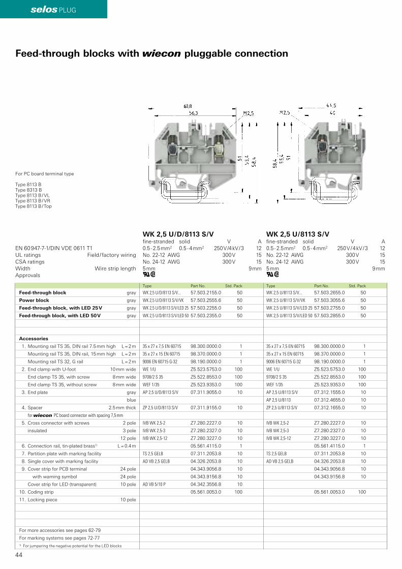
44
selos PLUG
WK 2,5 U/8113 S/V... 57.503.2655.0 50
WK 2,5 U/8113 S/V/VK 57.503.3055.6 50
WK 2,5 U/8113 S/V/LED 25 57.503.2755.0 50
WK 2,5 U/8113 S/V/LED 50 57.503.2855.0 50
35 x 27 x 7,5 EN 60715 98.300.0000.0 1
35 x 27 x 15 EN 60715 98.370.0000.0 1
9006 EN 60715 G-32 98.190.0000.0 1
WE 1/U Z5.523.5753.0 100
9708/2 S 35 Z5.522.8553.0 100
WEF 1/35 Z5.523.9353.0 100
AP 2,5 U/8113 S/V 07.312.1555.0 10
AP 2,5 U/8113 07.312.4655.0 10
ZP 2,5 U/8113 S/V 07.312.1655.0 10
IVB WK 2,5-2 Z7.280.2227.0 10
IVB WK 2,5-3 Z7.280.2327.0 10
IVB WK 2,5-12 Z7.280.3227.0 10
05.561.4115.0 1
TS 2,5 GELB 07.311.2053.8 10
AD VB 2,5 GELB 04.326.2053.8 10
04.343.9056.8 10
04.343.9156.8 10
05.561.0053.0 100
WK 2,5 U/D/8113 S/V... 57.503.2155.0 50
WK 2,5 U/D/8113 S/V/VK 57.503.2555.6 50
WK 2,5 U/D/8113 S/V/LED 25 57.503.2255.0 50
WK 2,5 U/D/8113 S/V/LED 50 57.503.2355.0 50
35 x 27 x 7,5 EN 60715 98.300.0000.0 1
35 x 27 x 15 EN 60715 98.370.0000.0 1
9006 EN 60715 G-32 98.190.0000.0 1
WE 1/U Z5.523.5753.0 100
9708/2 S 35 Z5.522.8553.0 100
WEF 1/35 Z5.523.9353.0 100
AP 2,5 U/D/8113 S/V 07.311.9055.0 10
ZP 2,5 U/D/8113 S/V 07.311.9155.0 10
IVB WK 2,5-2 Z7.280.2227.0 10
IVB WK 2,5-3 Z7.280.2327.0 10
IVB WK 2,5-12 Z7.280.3227.0 10
05.561.4115.0 1
TS 2,5 GELB 07.311.2053.8 10
AD VB 2,5 GELB 04.326.2053.8 10
04.343.9056.8 10
04.343.9156.8 10
AD VB 5/10 P 04.342.3556.8 10
05.561.0053.0 100
qw qw
EN 60 947-7-1/DIN VDE 0611 T1
Type Part No. Std. PackType Part No. Std. Pack
UL ratings Field / factory wiring
CSA ratings
Width Wire strip length
Approvals
Feed-through blocks with wiecon pluggable connection
WK 2,5 U / D / 8113 S / Vfine-stranded solid V A
0.5 - 2.5 mm2 0.5 - 4 mm2 250 V /4 kV / 3 12
No. 22-12 AWG 300 V 15
No. 24-12 AWG 300 V 15
5 mm 9 mm
WK 2,5 U / 8113 S / Vfine-stranded solid V A
0.5 - 2.5 mm2 0.5 - 4 mm2 250 V / 4 kV / 3 12
No. 22-12 AWG 300 V 15
No. 24-12 AWG 300 V 15
5 mm 9 mm
For PC board terminal type
Type 8113 BType 8313 BType 8113 B / VLType 8113 B / VRType 8113 B / Top
Feed-through block gray
Power block gray
Feed-through block, with LED 25 V gray
Feed-through block, with LED 50 V gray
Accessories
1. Mounting rail TS 35, DIN rail 7.5 mm high L = 2 m
Mounting rail TS 35, DIN rail, 15 mm high L = 2 m
Mounting rail TS 32, G rail L = 2 m
2. End clamp with U-foot 10 mm wide
End clamp TS 35, with screw 8 mm wide
End clamp TS 35, without screw 8 mm wide
3. End plate gray
blue
4. Spacer 2.5 mm thick
for wiecon PC board connector with spacing 7,5 mm
5. Cross connector with screws 2 pole
insulated 3 pole
12 pole
6. Connection rail, tin-plated brass1) L = 0.4 m
7. Partition plate with marking facility
8. Single cover with marking facility
9. Cover strip for PCB terminal 24 pole
with warning symbol 24 pole
Cover strip for LED (transparent) 10 pole
10. Coding strip
11. Locking piece 10 pole
For more accessories see pages 62-79
For marking systems see pages 72-77
1) For jumpering the negative potential for the LED blocks
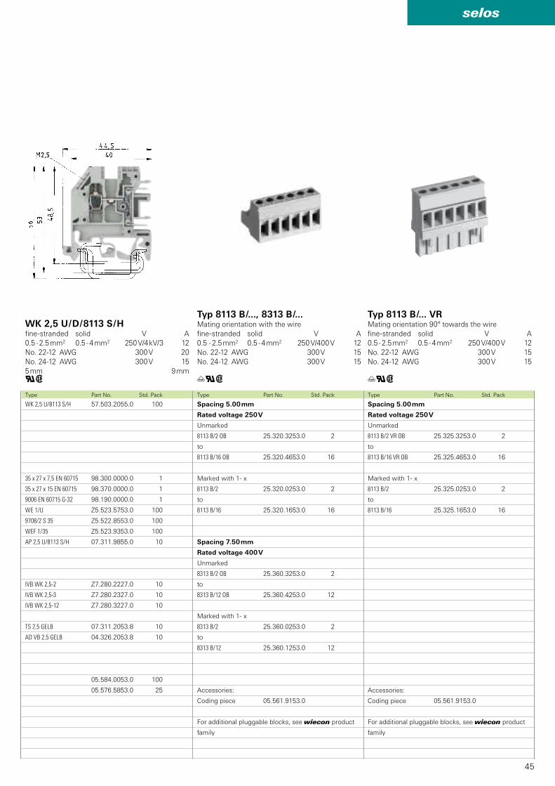
45
selos
8113 B/2 VR OB 25.325.3253.0 2
8113 B/16 VR OB 25.325.4653.0 16
8113 B/2 25.325.0253.0 2
8113 B/16 25.325.1653.0 16
05.561.9153.0
8113 B/2 OB 25.320.3253.0 2
8113 B/16 OB 25.320.4653.0 16
8113 B/2 25.320.0253.0 2
8113 B/16 25.320.1653.0 16
8313 B/2 OB 25.360.3253.0 2
8313 B/12 OB 25.360.4253.0 12
8313 B/2 25.360.0253.0 2
8313 B/12 25.360.1253.0 12
05.561.9153.0
WK 2,5 U/8113 S/H 57.503.2055.0 100
35 x 27 x 7,5 EN 60715 98.300.0000.0 1
35 x 27 x 15 EN 60715 98.370.0000.0 1
9006 EN 60715 G-32 98.190.0000.0 1
WE 1/U Z5.523.5753.0 100
9708/2 S 35 Z5.522.8553.0 100
WEF 1/35 Z5.523.9353.0 100
AP 2,5 U/8113 S/H 07.311.9855.0 10
IVB WK 2,5-2 Z7.280.2227.0 10
IVB WK 2,5-3 Z7.280.2327.0 10
IVB WK 2,5-12 Z7.280.3227.0 10
TS 2,5 GELB 07.311.2053.8 10
AD VB 2,5 GELB 04.326.2053.8 10
05.584.0053.0 100
05.576.5853.0 25
üqw üqwqwType Part No. Std. PackType Part No. Std. PackType Part No. Std. Pack
Typ 8113 B /..., 8313 B /...Mating orientation with the wire
fine-stranded solid V A
0.5 - 2.5 mm2 0.5 - 4 mm2 250 V/400 V 12
No. 22-12 AWG 300 V 15
No. 24-12 AWG 300 V 15
Typ 8113 B /... VRMating orientation 90° towards the wire
fine-stranded solid V A
0.5 - 2.5 mm2 0.5 - 4 mm2 250 V/400 V 12
No. 22-12 AWG 300 V 15
No. 24-12 AWG 300 V 15
WK 2,5 U / D / 8113 S / Hfine-stranded solid V A
0.5 - 2.5 mm2 0.5 - 4 mm2 250 V/4 kV/3 12
No. 22-12 AWG 300 V 20
No. 24-12 AWG 300 V 15
5 mm 9 mm
Spacing 5.00 mm
Rated voltage 250 V
Unmarked
to
Marked with 1- x
to
Spacing 7.50 mm
Rated voltage 400 V
Unmarked
to
Marked with 1- x
to
Accessories:
Coding piece
For additional pluggable blocks, see wiecon product
family
Spacing 5.00 mm
Rated voltage 250 V
Unmarked
to
Marked with 1- x
to
Accessories:
Coding piece
For additional pluggable blocks, see wiecon product
family
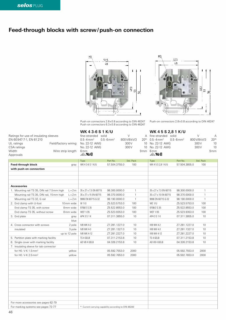
46
selos PLUG
WK 4 5 S 2,8 1 K/U 57.504.3855.0 100
35 x 27 x 7,5 EN 60715 98.300.0000.0 1
35 x 27 x 15 EN 60715 98.370.0000.0 1
9006 EN 60715 G-32 98.190.0000.0 1
WE 1/U Z5.523.5753.0 100
9708/2 S 35 Z5.522.8553.0 100
WEF 1/35 Z5.523.9353.0 100
AP4 3 S 1 K 07.311.3855.0 10
IVB WK 4-2 Z7.281.1227.0 10
IVB WK 4-3 Z7.281.1327.0 10
IVB WK 4-12 Z7.281.2227.0 10
TS 4 GELB 07.311.2153.8 10
AD VB 4 GELB 04.326.2153.8 10
05.592.7553.0 2000
05.592.7653.0 2000
WK 4 3-6 S 1 K/U 57.504.3755.0 100
35 x 27 x 7,5 EN 60715 98.300.0000.0 1
35 x 27 x 15 EN 60715 98.370.0000.0 1
9006 EN 60715 G-32 98.190.0000.0 1
W 1/U Z5.523.5753.0 100
9708/2 S 35 Z5.522.8553.0 100
WEF 1/35 Z5.523.9353.0 100
AP4 3 S 1 K 07.311.3855.0 10
IVB WK 4-2 Z7.281.1227.0 10
IVB WK 4-3 Z7.281.1327.0 10
IVB WK 4-12 Z7.281.2227.0 10
TS 4 GELB 07.311.2153.8 10
AD VB 4 GELB 04.326.2153.8 10
05.592.7553.0 2000
05.592.7653.0 2000
gqw gqw
EN 60 947-7-1, EN 61 210
Type Part No. Std. PackType Part No. Std. Pack
Ratings for use of insulating sleeves
UL ratings Field/factory wiring
CSA ratings
Width Wire strip length
Approvals
Feed-through blocks with screw / push-on connection
Feed-through block gray
with push-on connection
Accessories
1. Mounting rail TS 35, DIN rail 7.5 mm high L = 2 m
Mounting rail TS 35, DIN rail, 15 mm high L = 2 m
Mounting rail TS 32, G rail L = 2 m
2. End clamp with U-foot 10 mm wide
End clamp TS 35, with screw 8 mm wide
End clamp TS 35, without screw 8 mm wide
3. End plate gray
blue
4. Cross connector with screws 2 pole
insulated 3 pole
up to 12 pole
5. Partition plate with marking facility
6. Single cover with marking facility
7. Insulating sleeve for tab connector
for H0. V-K 1.5 mm2 yellow
for H0. V-K 2.5 mm2 yellow
For more accessories see pages 62-79
For marking systems see pages 72-77
WK 4 3-6 S 1 K / Ufine-stranded solid V A
0.5 - 4 mm2 0.5 - 6 mm2 800 V/8 kV/3 20*)
No. 22-12 AWG 300 V 10
No. 22-12 AWG 300 V 10
6 mm 9 mm
WK 4 5 S 2,8 1 K / Ufine-stranded solid V A
0.5 - 4 mm2 0.5 - 6 mm2 800 V/8 kV/3 20*)
No. 22-12 AWG 300 V 10
No. 22-12 AWG 300 V 10
6 mm 9 mm
Push-on connectors 2.8 x 0.8 according to DIN 46247Push-on connectors 6.3 x 0.8 according to DIN 46247
Push-on connectors 2.8 x 0.8 according to DIN 46247
*) Current carrying capability according to DIN 46249
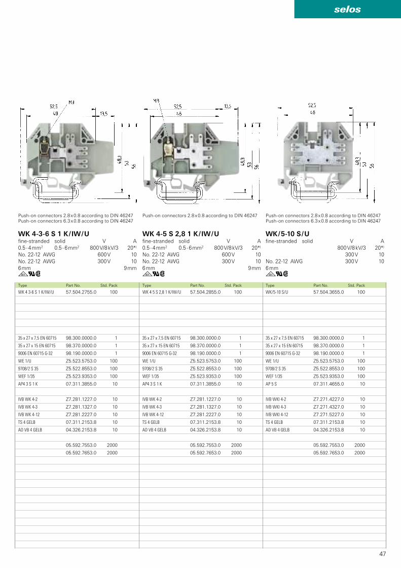
47
selos
WK/5-10 S/U 57.504.3655.0 100
35 x 27 x 7,5 EN 60715 98.300.0000.0 1
35 x 27 x 15 EN 60715 98.370.0000.0 1
9006 EN 60715 G-32 98.190.0000.0 1
WE 1/U Z5.523.5753.0 100
9708/2 S 35 Z5.522.8553.0 100
WEF 1/35 Z5.523.9353.0 100
AP 5 S 07.311.4655.0 10
IVB WKI 4-2 Z7.271.4227.0 10
IVB WKI 4-3 Z7.271.4327.0 10
IVB WKI 4-12 Z7.271.5227.0 10
TS 4 GELB 07.311.2153.8 10
AD VB 4 GELB 04.326.2153.8 10
05.592.7553.0 2000
05.592.7653.0 2000
WK 4 5 S 2,8 1 K/IW/U 57.504.2855.0 100
35 x 27 x 7,5 EN 60715 98.300.0000.0 1
35 x 27 x 15 EN 60715 98.370.0000.0 1
9006 EN 60715 G-32 98.190.0000.0 1
WE 1/U Z5.523.5753.0 100
9708/2 S 35 Z5.522.8553.0 100
WEF 1/35 Z5.523.9353.0 100
AP4 3 S 1 K 07.311.3855.0 10
IVB WK 4-2 Z7.281.1227.0 10
IVB WK 4-3 Z7.281.1327.0 10
IVB WK 4-12 Z7.281.2227.0 10
TS 4 GELB 07.311.2153.8 10
AD VB 4 GELB 04.326.2153.8 10
05.592.7553.0 2000
05.592.7653.0 2000
WK 4 3-6 S 1 K/IW/U 57.504.2755.0 100
35 x 27 x 7,5 EN 60715 98.300.0000.0 1
35 x 27 x 15 EN 60715 98.370.0000.0 1
9006 EN 60715 G-32 98.190.0000.0 1
WE 1/U Z5.523.5753.0 100
9708/2 S 35 Z5.522.8553.0 100
WEF 1/35 Z5.523.9353.0 100
AP4 3 S 1 K 07.311.3855.0 10
IVB WK 4-2 Z7.281.1227.0 10
IVB WK 4-3 Z7.281.1327.0 10
IVB WK 4-12 Z7.281.2227.0 10
TS 4 GELB 07.311.2153.8 10
AD VB 4 GELB 04.326.2153.8 10
05.592.7553.0 2000
05.592.7653.0 2000
gqw gqwgqwType Part No. Std. PackType Part No. Std. PackType Part No. Std. Pack
WK 4-5 S 2,8 1 K / IW / Ufine-stranded solid V A
0.5 - 4 mm2 0.5 - 6 mm2 800 V/8 kV/3 20*)
No. 22-12 AWG 600 V 10
No. 22-12 AWG 300 V 10
6 mm 9 mm
WK / 5-10 S / Ufine-stranded solid V A
800 V/8 kV/3 20*)
300 V 10
No. 22-12 AWG 300 V 10
6 mm
WK 4-3-6 S 1 K / IW / Ufine-stranded solid V A
0.5 - 4 mm2 0.5 - 6 mm2 800 V/8 kV/3 20*)
No. 22-12 AWG 600 V 10
No. 22-12 AWG 300 V 10
6 mm 9 mm
Push-on connectors 2.8 x 0.8 according to DIN 46247Push-on connectors 6.3 x 0.8 according to DIN 46247
Push-on connectors 2.8 x 0.8 according to DIN 46247 Push-on connectors 2.8 x 0.8 according to DIN 46247Push-on connectors 6.3 x 0.8 according to DIN 46247
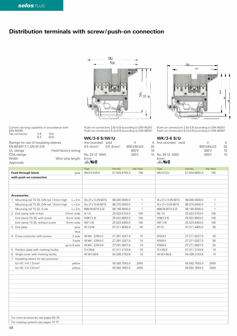
48
selos PLUG
WK/3-6 S/U 57.504.6655.0 100
35 x 27 x 7,5 EN 60715 98.300.0000.0 1
35 x 27 x 15 EN 60715 98.370.0000.0 1
9006 EN 60715 G-32 98.190.0000.0 1
WE 1/U Z5.523.5753.0 100
9708/2 S 35 Z5.522.8553.0 100
WEF 1/35 Z5.523.9353.0 100
AP 3 S 07.311.4455.0 50
9703/6-2 Z7.211.0227.0 50
9703/6-3 Z7.211.0327.0 50
9703/6-6 Z7.211.0627.0 50
TS 4 GELB 07.311.2153.8 10
AD VB 4 GELB 04.326.2153.8 10
05.592.7553.0 2000
05.592.7653.0 2000
WK/3-6 S/IW/U 57.504.6755.0 100
35 x 27 x 7,5 EN 60715 98.300.0000.0 1
35 x 27 x 15 EN 60715 98.370.0000.0 1
9006 EN 60715 G-32 98.190.0000.0 1
W 1/U Z5.523.5753.0 100
9708/2 S 35 Z5.522.8553.0 100
WEF 1/35 Z5.523.9353.0 100
AP 3 S/IW 07.311.4555.0 50
VB WK/...S/IW/U-2 Z7.281.3227.0 10
VB WK/...S/IW/U-3 Z7.281.3327.0 10
VB WK/...S/IW/U-6 Z7.281.3627.0 10
TS 4 GELB 07.311.2153.8 10
AD VB 4 GELB 04.326.2153.8 10
05.592.7553.0 2000
05.592.7653.0 2000
gqwgqw
EN 60 947-7-1, EN 61 210
Type Part No. Std. PackType Part No. Std. Pack
Ratings for use of insulating sleeves
UL ratings Field / factory wiring
CSA ratings
Width Wire strip length
Approvals
WK / 3-6 S / Ufine-stranded solid V A
800 V/8 kV/3 20
300 V 10
No. 24-12 AWG 300 V 10
6 mm
WK / 3-6 S / IW / Ufine-stranded solid V A
0.5 - 4 mm2 0.5 - 6 mm2 800 V/8 kV/3 20
600 V 10
No. 22-12 AWG 300 V 10
6 mm
Push-on connectors 2.8 x 0.8 according to DIN 46247Push-on connectors 6.3 x 0.8 according to DIN 46247
Push-on connectors 2.8 x 0.8 according to DIN 46247Push-on connectors 6.3 x 0.8 according to DIN 46247
Distribution terminals with screw / push-on connection
Feed-through block gray
with push-on connection
Accessories
1. Mounting rail TS 35, DIN rail 7.5 mm high L = 2 m
Mounting rail TS 35, DIN rail, 15 mm high L = 2 m
Mounting rail TS 32, G rail L = 2 m
2. End clamp with U-foot 10 mm wide
End clamp TS 35, with screw 8 mm wide
End clamp TS 35, without screw 8 mm wide
3. End plate gray
blue
4. Cross connector with screws 2 pole
3 pole
up to 6 pole
5. Partition plate with marking facility
6. Single cover with marking facility
7. Insulating sleeve for tab connector
for H0. V-K 1.5 mm2 yellow
for H0. V-K 2.5 mm2 yellow
For more accessories see pages 62-79
For marking systems see pages 72-77
Current carrying capability in accordance with DIN 46249Tab connector 2.8 10 A 6.3 20 A
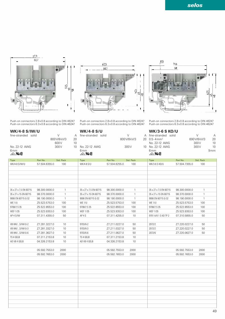
49
selos
WK/3-6 S KO/U 57.504.7355.0 100
35 x 27 x 7,5 EN 60715 98.300.0000.0 1
35 x 27 x 15 EN 60715 98.370.0000.0 1
9006 EN 60715 G-32 98.190.0000.0 1
WE 1/U Z5.523.5753.0 100
9708/2 S 35 Z5.522.8553.0 100
WEF 1/35 Z5.523.9353.0 100
9701 A/6 1 S KO TP 2 07.310.5855.0 50
2072/2 Z7.220.0227.0 50
2072/2 Z7.220.0227.0 50
2072/6 Z7.220.0627.0 50
05.592.7553.0 2000
05.592.7653.0 2000
WK/4-8 S/U 57.504.6255.0 100
35 x 27 x 7,5 EN 60715 98.300.0000.0 1
35 x 27 x 15 EN 60715 98.370.0000.0 1
9006 EN 60715 G-32 98.190.0000.0 1
WE 1/U Z5.523.5753.0 100
9708/2 S 35 Z5.522.8553.0 100
WEF 1/35 Z5.523.9353.0 100
AP 4 S 07.311.4255.0 10
9703/6-2 Z7.211.0227.0 50
9703/6-3 Z7.211.0327.0 50
9703/6-6 Z7.211.0627.0 50
TS 4 GELB 07.311.2153.8 10
AD VB 4 GELB 04.326.2153.8 10
05.592.7553.0 2000
05.592.7653.0 2000
WK/4-8 S/IW/U 57.504.6355.0 100
35 x 27 x 7,5 EN 60715 98.300.0000.0 1
35 x 27 x 15 EN 60715 98.370.0000.0 1
9006 EN 60715 G-32 98.190.0000.0 1
WE 1/U Z5.523.5753.0 100
9708/2 S 35 Z5.522.8553.0 100
WEF 1/35 Z5.523.9353.0 100
AP 4 S/IW 07.311.4355.0 50
VB WK/...S/IW/U-2 Z7.281.3227.0 10
VB WK/...S/IW/U-3 Z7.281.3327.0 10
VB WK/...S/IW/U-6 Z7.281.3627.0 10
TS 4 GELB 07.311.2153.8 10
AD VB 4 GELB 04.326.2153.8 10
05.592.7553.0 2000
05.592.7653.0 2000
gqw gqwgqwType Part No. Std. PackType Part No. Std. PackType Part No. Std. Pack
WK / 4-8 S / Ufine-stranded solid V A
800 V/8 kV/3 20
No. 22-12 AWG 300 V 10
6 mm
WK / 3-6 S KO / Ufine-stranded solid V A
0.5 - 4 mm2 690 V/8 kV/3 20
No. 22-12 AWG 300 V 10
No. 22-12 AWG 300 V 10
6 mm 9 mm
WK / 4-8 S / IW / Ufine-stranded solid V A
800 V/8 kV/3 20
600 V 10
No. 22-12 AWG 300 V 10
6 mm
Push-on connectors 2.8 x 0.8 according to DIN 46247Push-on connectors 6.3 x 0.8 according to DIN 46247
Push-on connectors 2.8 x 0.8 according to DIN 46247Push-on connectors 6.3 x 0.8 according to DIN 46247
Push-on connectors 2.8 x 0.8 according to DIN 46247Push-on connectors 6.3 x 0.8 according to DIN 46247
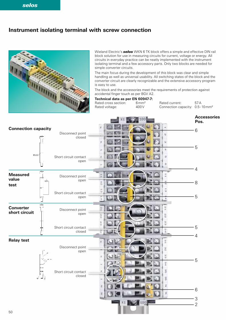
50
selos
6
5
4
8
5
5
5
6
32
4
Instrument isolating terminal with screw connection
AccessoriesPos.
Short circuit contactopen
Connection capacity
Measured value
test
Convertershort circuit
Relay test
Short circuit contactopen
Short circuit contactclosed
Short circuit contactclosed
Disconnect pointclosed
Disconnect pointopen
Disconnect pointopen
Disconnect pointopen
Wieland Electric‘s selos WKN 6 TK block offers a simple and effective DIN rail block solution for use in measuring circuits for current, voltage or energy. All circuits in everyday practice can be neatly implemented with the instrument isolating terminal and a few accessory parts. Only two blocks are needed for simple converter circuits.
The main focus during the development of this block was clear and simple handling as well as universal usability. All switching states of the block and the converter circuit are clearly recognizable and the extensive accessory program is easy to use.
The block and the accessories meet the requirements of protection against accidental finger touch as per BGV A2.
Technical data as per EN 60947-7:Rated cross section: 6 mm² Rated current: 57 ARated voltage: 400 V Connection capacity: 0.5 - 10 mm²
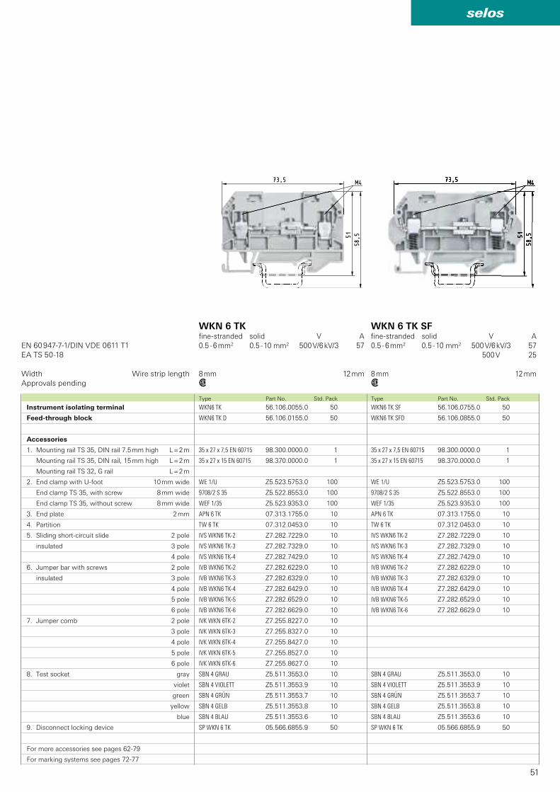
51
selos
WKN6 TK 56.106.0055.0 50
WKN6 TK D 56.106.0155.0 50
35 x 27 x 7,5 EN 60715 98.300.0000.0 1
35 x 27 x 15 EN 60715 98.370.0000.0 1
WE 1/U Z5.523.5753.0 100
9708/2 S 35 Z5.522.8553.0 100
WEF 1/35 Z5.523.9353.0 100
APN 6 TK 07.313.1755.0 10
TW 6 TK 07.312.0453.0 10
IVS WKN6 TK-2 Z7.282.7229.0 10
IVS WKN6 TK-3 Z7.282.7329.0 10
IVS WKN6 TK-4 Z7.282.7429.0 10
IVB WKN6 TK-2 Z7.282.6229.0 10
IVB WKN6 TK-3 Z7.282.6329.0 10
IVB WKN6 TK-4 Z7.282.6429.0 10
IVB WKN6 TK-5 Z7.282.6529.0 10
IVB WKN6 TK-6 Z7.282.6629.0 10
IVK WKN 6TK-2 Z7.255.8227.0 10
IVK WKN 6TK-3 Z7.255.8327.0 10
IVK WKN 6TK-4 Z7.255.8427.0 10
IVK WKN 6TK-5 Z7.255.8527.0 10
IVK WKN 6TK-6 Z7.255.8627.0 10
SBN 4 GRAU Z5.511.3553.0 10
SBN 4 VIOLETT Z5.511.3553.9 10
SBN 4 GRÜN Z5.511.3553.7 10
SBN 4 GELB Z5.511.3553.8 10
SBN 4 BLAU Z5.511.3553.6 10
SP WKN 6 TK 05.566.6855.9 50
WKN6 TK SF 56.106.0755.0 50
WKN6 TK SFD 56.106.0855.0 50
35 x 27 x 7,5 EN 60715 98.300.0000.0 1
35 x 27 x 15 EN 60715 98.370.0000.0 1
WE 1/U Z5.523.5753.0 100
9708/2 S 35 Z5.522.8553.0 100
WEF 1/35 Z5.523.9353.0 100
APN 6 TK 07.313.1755.0 10
TW 6 TK 07.312.0453.0 10
IVS WKN6 TK-2 Z7.282.7229.0 10
IVS WKN6 TK-3 Z7.282.7329.0 10
IVS WKN6 TK-4 Z7.282.7429.0 10
IVB WKN6 TK-2 Z7.282.6229.0 10
IVB WKN6 TK-3 Z7.282.6329.0 10
IVB WKN6 TK-4 Z7.282.6429.0 10
IVB WKN6 TK-5 Z7.282.6529.0 10
IVB WKN6 TK-6 Z7.282.6629.0 10
SBN 4 GRAU Z5.511.3553.0 10
SBN 4 VIOLETT Z5.511.3553.9 10
SBN 4 GRÜN Z5.511.3553.7 10
SBN 4 GELB Z5.511.3553.8 10
SBN 4 BLAU Z5.511.3553.6 10
SP WKN 6 TK 05.566.6855.9 50
w w
EN 60 947-7-1/DIN VDE 0611 T1EA TS 50-18
Type Part No. Std. Pack Type Part No. Std. Pack
Instrument isolating terminal
Feed-through block
Accessories
1. Mounting rail TS 35, DIN rail 7.5 mm high L = 2 m
Mounting rail TS 35, DIN rail, 15 mm high L = 2 m
Mounting rail TS 32, G rail L = 2 m
2. End clamp with U-foot 10 mm wide
End clamp TS 35, with screw 8 mm wide
End clamp TS 35, without screw 8 mm wide
3. End plate 2 mm
4. Partition
5. Sliding short-circuit slide 2 pole
insulated 3 pole
4 pole
6. Jumper bar with screws 2 pole
insulated 3 pole
4 pole
5 pole
6 pole
7. Jumper comb 2 pole
3 pole
4 pole
5 pole
6 pole
8. Test socket gray
violet
green
yellow
blue
9. Disconnect locking device
For more accessories see pages 62-79
For marking systems see pages 72-77
Width Wire strip lengthApprovals pending
WKN 6 TK fine-stranded solid V A0.5 - 6 mm2 0.5 - 10 mm2 500 V/6 kV/3 57
8 mm 12 mm
WKN 6 TK SFfine-stranded solid V A0.5 - 6 mm2 0.5 - 10 mm2 500 V/6 kV/3 57 500 V 25
8 mm 12 mm
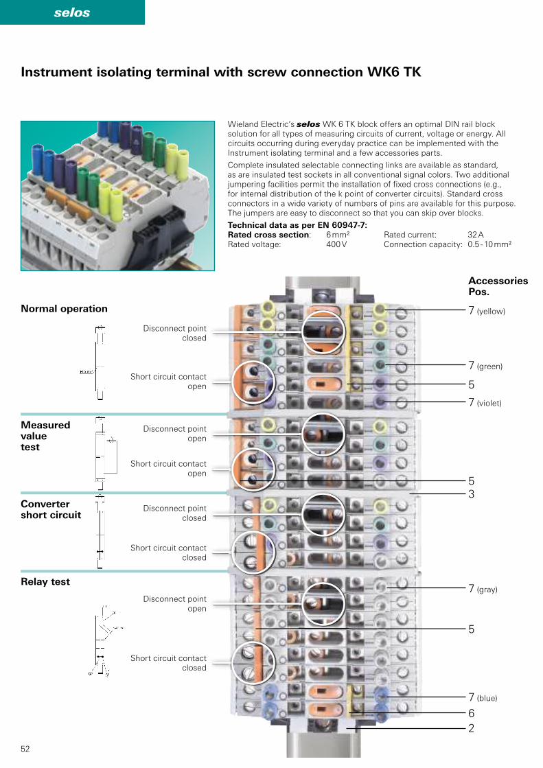
52
selos
7
7
7
53
5
7
7
62
5
Instrument isolating terminal with screw connection WK6 TK
(yellow)
(green)
(violet)
(gray)
(blue)
AccessoriesPos.
Wieland Electric‘s selos WK 6 TK block offers an optimal DIN rail block solution for all types of measuring circuits of current, voltage or energy. All circuits occurring during everyday practice can be implemented with the Instrument isolating terminal and a few accessories parts.
Complete insulated selectable connecting links are available as standard, as are insulated test sockets in all conventional signal colors. Two additional jumpering facilities permit the installation of fixed cross connections (e.g., for internal distribution of the k point of converter circuits). Standard cross connectors in a wide variety of numbers of pins are available for this purpose. The jumpers are easy to disconnect so that you can skip over blocks.
Technical data as per EN 60947-7:Rated cross section: 6 mm² Rated current: 32 ARated voltage: 400 V Connection capacity: 0.5 - 10 mm²
Short circuit contactopen
Normal operation
Measured valuetest
Convertershort circuit
Relay test
Short circuit contactopen
Short circuit contactclosed
Short circuit contactclosed
Disconnect pointclosed
Disconnect pointopen
Disconnect pointclosed
Disconnect pointopen
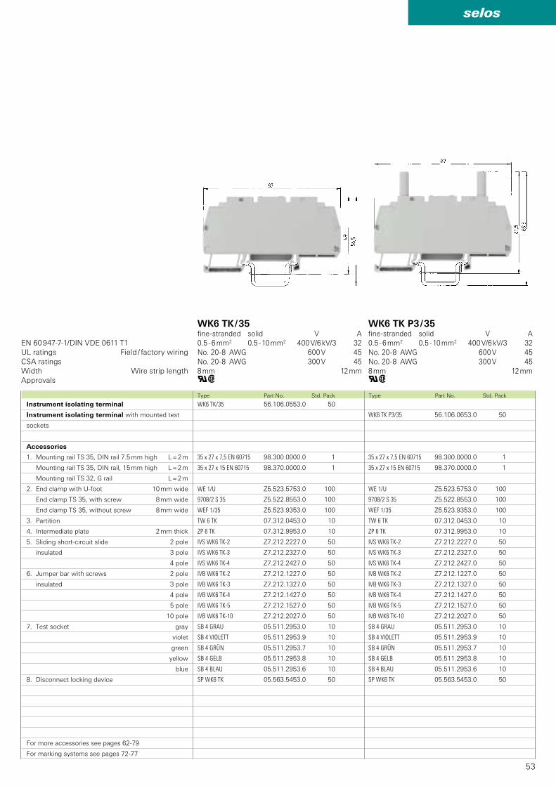
53
selos
WK6 TK P3/35 56.106.0653.0 50
35 x 27 x 7,5 EN 60715 98.300.0000.0 1
35 x 27 x 15 EN 60715 98.370.0000.0 1
WE 1/U Z5.523.5753.0 100
9708/2 S 35 Z5.522.8553.0 100
WEF 1/35 Z5.523.9353.0 100
TW 6 TK 07.312.0453.0 10
ZP 6 TK 07.312.9953.0 10
IVS WK6 TK-2 Z7.212.2227.0 50
IVS WK6 TK-3 Z7.212.2327.0 50
IVS WK6 TK-4 Z7.212.2427.0 50
IVB WK6 TK-2 Z7.212.1227.0 50
IVB WK6 TK-3 Z7.212.1327.0 50
IVB WK6 TK-4 Z7.212.1427.0 50
IVB WK6 TK-5 Z7.212.1527.0 50
IVB WK6 TK-10 Z7.212.2027.0 50
SB 4 GRAU 05.511.2953.0 10
SB 4 VIOLETT 05.511.2953.9 10
SB 4 GRÜN 05.511.2953.7 10
SB 4 GELB 05.511.2953.8 10
SB 4 BLAU 05.511.2953.6 10
SP WK6 TK 05.563.5453.0 50
WK6 TK/35 56.106.0553.0 50
35 x 27 x 7,5 EN 60715 98.300.0000.0 1
35 x 27 x 15 EN 60715 98.370.0000.0 1
WE 1/U Z5.523.5753.0 100
9708/2 S 35 Z5.522.8553.0 100
WEF 1/35 Z5.523.9353.0 100
TW 6 TK 07.312.0453.0 10
ZP 6 TK 07.312.9953.0 10
IVS WK6 TK-2 Z7.212.2227.0 50
IVS WK6 TK-3 Z7.212.2327.0 50
IVS WK6 TK-4 Z7.212.2427.0 50
IVB WK6 TK-2 Z7.212.1227.0 50
IVB WK6 TK-3 Z7.212.1327.0 50
IVB WK6 TK-4 Z7.212.1427.0 50
IVB WK6 TK-5 Z7.212.1527.0 50
IVB WK6 TK-10 Z7.212.2027.0 50
SB 4 GRAU 05.511.2953.0 10
SB 4 VIOLETT 05.511.2953.9 10
SB 4 GRÜN 05.511.2953.7 10
SB 4 GELB 05.511.2953.8 10
SB 4 BLAU 05.511.2953.6 10
SP WK6 TK 05.563.5453.0 50
qw qw
EN 60 947-7-1/DIN VDE 0611 T1
Type Part No. Std. Pack
Instrument isolating terminal
Instrument isolating terminal with mounted test
sockets
Accessories
1. Mounting rail TS 35, DIN rail 7.5 mm high L = 2 m
Mounting rail TS 35, DIN rail, 15 mm high L = 2 m
Mounting rail TS 32, G rail L = 2 m
2. End clamp with U-foot 10 mm wide
End clamp TS 35, with screw 8 mm wide
End clamp TS 35, without screw 8 mm wide
3. Partition
4. Intermediate plate 2 mm thick
5. Sliding short-circuit slide 2 pole
insulated 3 pole
4 pole
6. Jumper bar with screws 2 pole
insulated 3 pole
4 pole
5 pole
10 pole
7. Test socket gray
violet
green
yellow
blue
8. Disconnect locking device
For more accessories see pages 62-79
For marking systems see pages 72-77
UL ratings Field / factory wiringCSA ratingsWidth Wire strip lengthApprovals
WK6 TK / 35fine-stranded solid V A0.5 - 6 mm2 0.5 - 10 mm2 400 V/6 kV/3 32No. 20-8 AWG 600 V 45No. 20-8 AWG 300 V 458 mm 12 mm
WK6 TK P3 / 35fine-stranded solid V A0.5 - 6 mm2 0.5 - 10 mm2 400 V/6 kV/3 32No. 20-8 AWG 600 V 45No. 20-8 AWG 300 V 458 mm 12 mm
Type Part No. Std. Pack
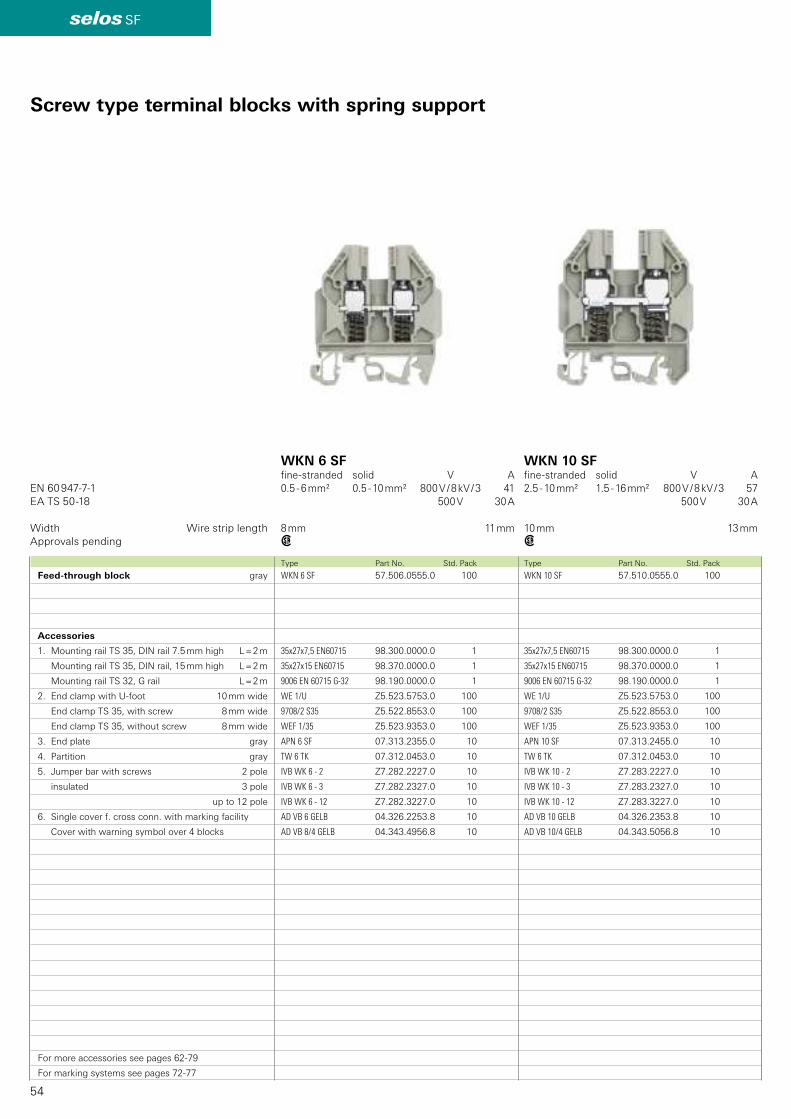
54
selos SF
WKN 10 SF 57.510.0555.0 100
35x27x7,5 EN60715 98.300.0000.0 1
35x27x15 EN60715 98.370.0000.0 1
9006 EN 60715 G-32 98.190.0000.0 1
WE 1/U Z5.523.5753.0 100
9708/2 S35 Z5.522.8553.0 100
WEF 1/35 Z5.523.9353.0 100
APN 10 SF 07.313.2455.0 10
TW 6 TK 07.312.0453.0 10
IVB WK 10 - 2 Z7.283.2227.0 10
IVB WK 10 - 3 Z7.283.2327.0 10
IVB WK 10 - 12 Z7.283.3227.0 10
AD VB 10 GELB 04.326.2353.8 10
AD VB 10/4 GELB 04.343.5056.8 10
WKN 6 SF 57.506.0555.0 100
35x27x7,5 EN60715 98.300.0000.0 1
35x27x15 EN60715 98.370.0000.0 1
9006 EN 60715 G-32 98.190.0000.0 1
WE 1/U Z5.523.5753.0 100
9708/2 S35 Z5.522.8553.0 100
WEF 1/35 Z5.523.9353.0 100
APN 6 SF 07.313.2355.0 10
TW 6 TK 07.312.0453.0 10
IVB WK 6 - 2 Z7.282.2227.0 10
IVB WK 6 - 3 Z7.282.2327.0 10
IVB WK 6 - 12 Z7.282.3227.0 10
AD VB 6 GELB 04.326.2253.8 10
AD VB 8/4 GELB 04.343.4956.8 10
EN 60 947-7-1EA TS 50-18
w w
Screw type terminal blocks with spring support
Feed-through block gray
Accessories
1. Mounting rail TS 35, DIN rail 7.5 mm high L = 2 m
Mounting rail TS 35, DIN rail, 15 mm high L = 2 m
Mounting rail TS 32, G rail L = 2 m
2. End clamp with U-foot 10 mm wide
End clamp TS 35, with screw 8 mm wide
End clamp TS 35, without screw 8 mm wide
3. End plate gray
4. Partition gray
5. Jumper bar with screws 2 pole
insulated 3 pole
up to 12 pole
6. Single cover f. cross conn. with marking facility
Cover with warning symbol over 4 blocks
For more accessories see pages 62-79
For marking systems see pages 72-77
WKN 6 SF fine-stranded solid V A0.5 - 6 mm² 0.5 - 10 mm² 800 V / 8 kV / 3 41 500 V 30 A
8 mm 11 mm
WKN 10 SFfine-stranded solid V A2.5 - 10 mm² 1.5 - 16 mm² 800 V / 8 kV / 3 57 500 V 30 A
10 mm 13 mm
Type Part No. Std. Pack Type Part No. Std. Pack
Width Wire strip lengthApprovals pending
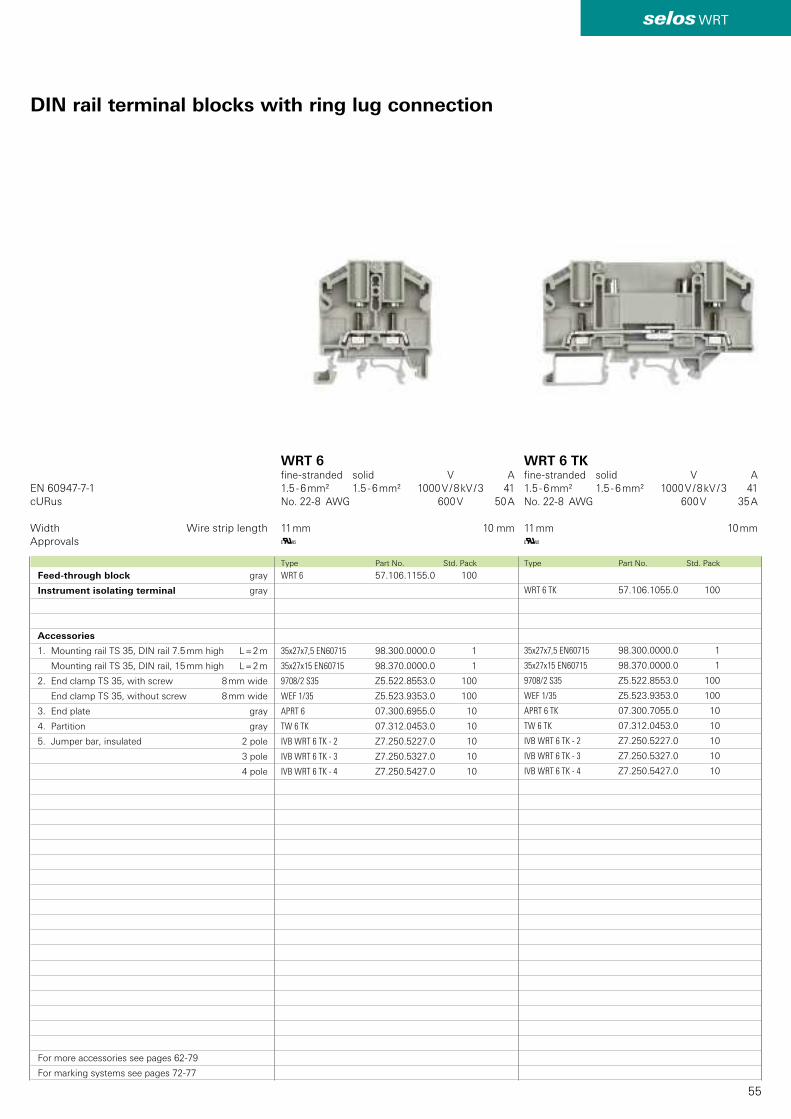
55
selos WRT
WRT 6 TK 57.106.1055.0 100
35x27x7,5 EN60715 98.300.0000.0 1
35x27x15 EN60715 98.370.0000.0 1
9708/2 S35 Z5.522.8553.0 100
WEF 1/35 Z5.523.9353.0 100
APRT 6 TK 07.300.7055.0 10
TW 6 TK 07.312.0453.0 10
IVB WRT 6 TK - 2 Z7.250.5227.0 10
IVB WRT 6 TK - 3 Z7.250.5327.0 10
IVB WRT 6 TK - 4 Z7.250.5427.0 10
WRT 6 57.106.1155.0 100
35x27x7,5 EN60715 98.300.0000.0 1
35x27x15 EN60715 98.370.0000.0 1
9708/2 S35 Z5.522.8553.0 100
WEF 1/35 Z5.523.9353.0 100
APRT 6 07.300.6955.0 10
TW 6 TK 07.312.0453.0 10
IVB WRT 6 TK - 2 Z7.250.5227.0 10
IVB WRT 6 TK - 3 Z7.250.5327.0 10
IVB WRT 6 TK - 4 Z7.250.5427.0 10
EN 60947-7-1 cURus
K K
Feed-through block gray
Instrument isolating terminal gray
Accessories
1. Mounting rail TS 35, DIN rail 7.5 mm high L = 2 m
Mounting rail TS 35, DIN rail, 15 mm high L = 2 m
2. End clamp TS 35, with screw 8 mm wide
End clamp TS 35, without screw 8 mm wide
3. End plate gray
4. Partition gray
5. Jumper bar, insulated 2 pole
3 pole
4 pole
For more accessories see pages 62-79
For marking systems see pages 72-77
WRT 6 TKfine-stranded solid V A1.5 - 6 mm² 1.5 - 6 mm² 1000 V / 8 kV / 3 41No. 22-8 AWG 600 V 35 A 11 mm 10 mm
DIN rail terminal blocks with ring lug connection
Width Wire strip lengthApprovals
Type Part No. Std. Pack Type Part No. Std. Pack
WRT 6 fine-stranded solid V A1.5 - 6 mm² 1.5 - 6 mm² 1000 V / 8 kV / 3 41No. 22-8 AWG 600 V 50 A 11 mm 10 mm
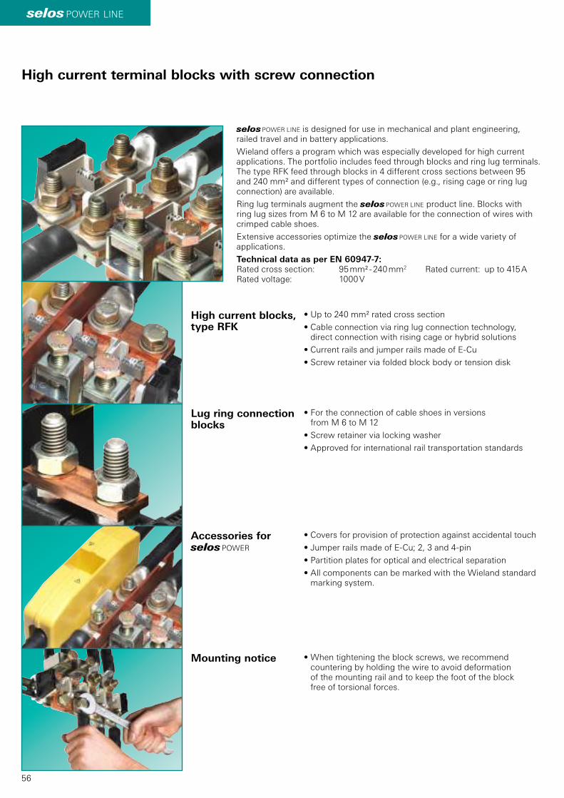
56
selos POWER LINE
High current terminal blocks with screw connection
• Up to 240 mm² rated cross section
• Cable connection via ring lug connection technology, direct connection with rising cage or hybrid solutions
• Current rails and jumper rails made of E-Cu
• Screw retainer via folded block body or tension disk
• For the connection of cable shoes in versions from M 6 to M 12
• Screw retainer via locking washer
• Approved for international rail transportation standards
• Covers for provision of protection against accidental touch
• Jumper rails made of E-Cu; 2, 3 and 4-pin
• Partition plates for optical and electrical separation
• All components can be marked with the Wieland standard marking system.
• When tightening the block screws, we recommend countering by holding the wire to avoid deformation of the mounting rail and to keep the foot of the block free of torsional forces.
High current blocks, type RFK
Lug ring connection blocks
Accessories for selos POWER
Mounting notice
selos POWER LINE is designed for use in mechanical and plant engineering, railed travel and in battery applications.
Wieland offers a program which was especially developed for high current applications. The portfolio includes feed through blocks and ring lug terminals. The type RFK feed through blocks in 4 different cross sections between 95 and 240 mm² and different types of connection (e.g., rising cage or ring lug connection) are available.
Ring lug terminals augment the selos POWER LINE product line. Blocks with ring lug sizes from M 6 to M 12 are available for the connection of wires with crimped cable shoes.
Extensive accessories optimize the selos POWER LINE for a wide variety of applications.
Technical data as per EN 60947-7:Rated cross section: 95 mm² - 240 mm2 Rated current: up to 415 ARated voltage: 1000 V
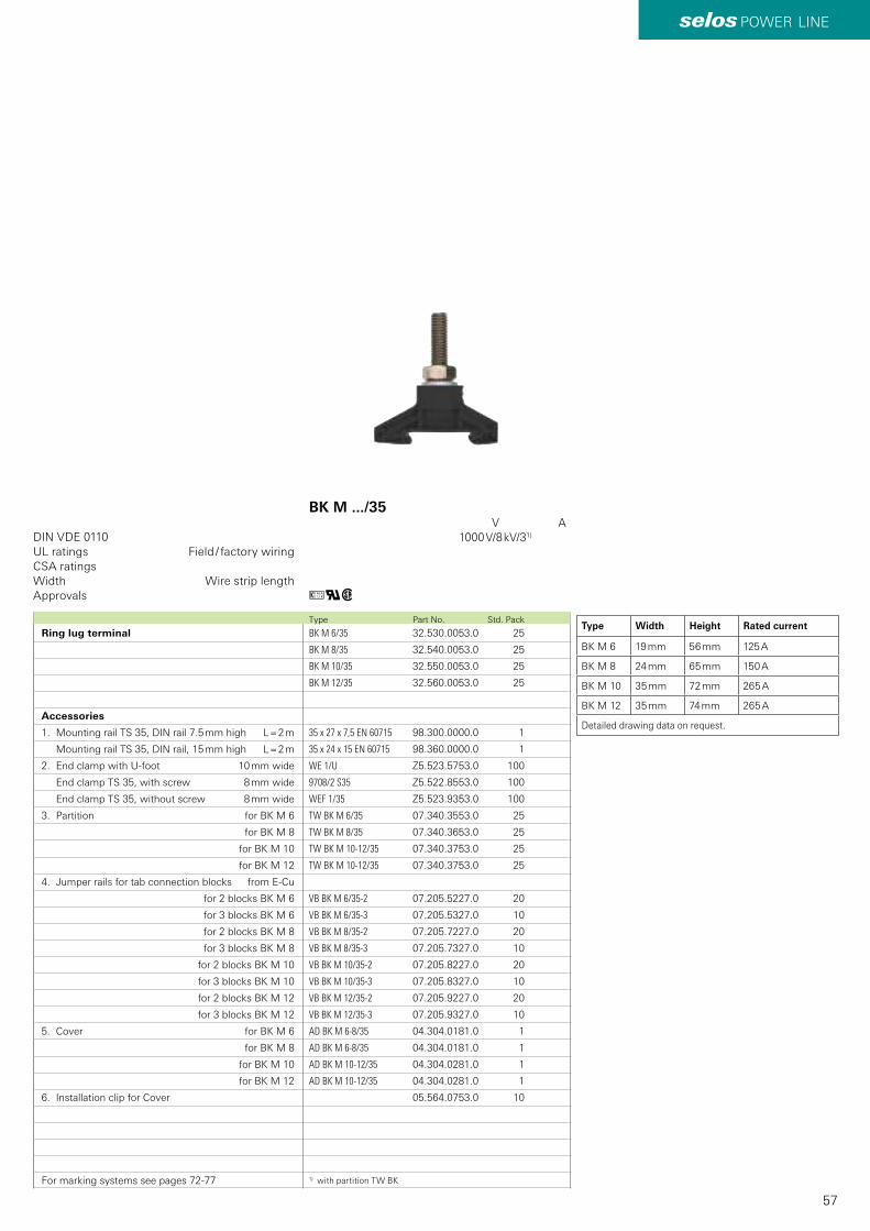
57
selos POWER LINE
BK M 6/35 32.530.0053.0 25
BK M 8/35 32.540.0053.0 25
BK M 10/35 32.550.0053.0 25
BK M 12/35 32.560.0053.0 25
35 x 27 x 7,5 EN 60715 98.300.0000.0 1
35 x 24 x 15 EN 60715 98.360.0000.0 1
WE 1/U Z5.523.5753.0 100
9708/2 S35 Z5.522.8553.0 100
WEF 1/35 Z5.523.9353.0 100
TW BK M 6/35 07.340.3553.0 25
TW BK M 8/35 07.340.3653.0 25
TW BK M 10-12/35 07.340.3753.0 25
TW BK M 10-12/35 07.340.3753.0 25
VB BK M 6/35-2 07.205.5227.0 20
VB BK M 6/35-3 07.205.5327.0 10
VB BK M 8/35-2 07.205.7227.0 20
VB BK M 8/35-3 07.205.7327.0 10
VB BK M 10/35-2 07.205.8227.0 20
VB BK M 10/35-3 07.205.8327.0 10
VB BK M 12/35-2 07.205.9227.0 20
VB BK M 12/35-3 07.205.9327.0 10
AD BK M 6-8/35 04.304.0181.0 1
AD BK M 6-8/35 04.304.0181.0 1
AD BK M 10-12/35 04.304.0281.0 1
AD BK M 10-12/35 04.304.0281.0 1
05.564.0753.0 10
BK M 6 19 mm 56 mm 125 A
BK M 8 24 mm 65 mm 150 A
BK M 10 35 mm 72 mm 265 A
BK M 12 35 mm 74 mm 265 A
uqw
DIN VDE 0110
Type Part No. Std. Pack
Ring lug terminal
Accessories
1. Mounting rail TS 35, DIN rail 7.5 mm high L = 2 m
Mounting rail TS 35, DIN rail, 15 mm high L = 2 m
2. End clamp with U-foot 10 mm wide
End clamp TS 35, with screw 8 mm wide
End clamp TS 35, without screw 8 mm wide
3. Partition for BK M 6
for BK M 8
for BK M 10
for BK M 12
4. Jumper rails for tab connection blocks from E-Cu
for 2 blocks BK M 6
for 3 blocks BK M 6
for 2 blocks BK M 8
for 3 blocks BK M 8
for 2 blocks BK M 10
for 3 blocks BK M 10
for 2 blocks BK M 12
for 3 blocks BK M 12
5. Cover for BK M 6
for BK M 8
for BK M 10
for BK M 12
6. Installation clip for Cover
For marking systems see pages 72-77
UL ratings Field / factory wiringCSA ratingsWidth Wire strip lengthApprovals
BK M .../35 V A 1000 V/8 kV/31)
1) with partition TW BK
Type Width Height Rated current
Detailed drawing data on request.
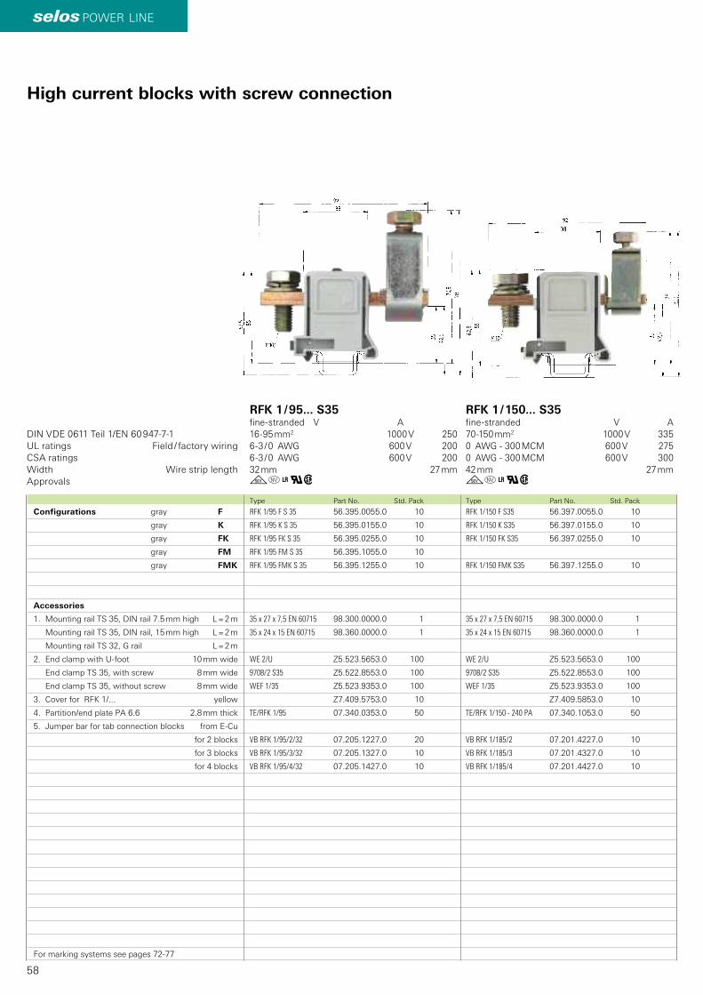
58
selos POWER LINE
RFK 1/150 F S35 56.397.0055.0 10
RFK 1/150 K S35 56.397.0155.0 10
RFK 1/150 FK S35 56.397.0255.0 10
RFK 1/150 FMK S35 56.397.1255.0 10
35 x 27 x 7,5 EN 60715 98.300.0000.0 1
35 x 24 x 15 EN 60715 98.360.0000.0 1
WE 2/U Z5.523.5653.0 100
9708/2 S35 Z5.522.8553.0 100
WEF 1/35 Z5.523.9353.0 100
Z7.409.5853.0 10
TE/RFK 1/150 - 240 PA 07.340.1053.0 50
VB RFK 1/185/2 07.201.4227.0 10
VB RFK 1/185/3 07.201.4327.0 10
VB RFK 1/185/4 07.201.4427.0 10
RFK 1/95 F S 35 56.395.0055.0 10
RFK 1/95 K S 35 56.395.0155.0 10
RFK 1/95 FK S 35 56.395.0255.0 10
RFK 1/95 FM S 35 56.395.1055.0 10
RFK 1/95 FMK S 35 56.395.1255.0 10
35 x 27 x 7,5 EN 60715 98.300.0000.0 1
35 x 24 x 15 EN 60715 98.360.0000.0 1
WE 2/U Z5.523.5653.0 100
9708/2 S35 Z5.522.8553.0 100
WEF 1/35 Z5.523.9353.0 100
Z7.409.5753.0 10
TE/RFK 1/95 07.340.0353.0 50
VB RFK 1/95/2/32 07.205.1227.0 20
VB RFK 1/95/3/32 07.205.1327.0 10
VB RFK 1/95/4/32 07.205.1427.0 10
go+qw go+qw
DIN VDE 0611 Teil 1/EN 60 947-7-1
Type Part No. Std. PackType Part No. Std. Pack
High current blocks with screw connection
Configurations gray F
gray K
gray FK
gray FM
gray FMK
Accessories
1. Mounting rail TS 35, DIN rail 7.5 mm high L = 2 m
Mounting rail TS 35, DIN rail, 15 mm high L = 2 m
Mounting rail TS 32, G rail L = 2 m
2. End clamp with U-foot 10 mm wide
End clamp TS 35, with screw 8 mm wide
End clamp TS 35, without screw 8 mm wide
3. Cover for RFK 1/... yellow
4. Partition/end plate PA 6.6 2.8 mm thick
5. Jumper bar for tab connection blocks from E-Cu
for 2 blocks
for 3 blocks
for 4 blocks
For marking systems see pages 72-77
UL ratings Field / factory wiringCSA ratingsWidth Wire strip lengthApprovals
RFK 1 / 95... S35fine-stranded V A16-95 mm2 1000 V 2506-3 / 0 AWG 600 V 2006-3 / 0 AWG 600 V 20032 mm 27 mm
RFK 1 / 150... S35fine-stranded V A70-150 mm2 1000 V 3350 AWG - 300 MCM 600 V 2750 AWG - 300 MCM 600 V 30042 mm 27 mm
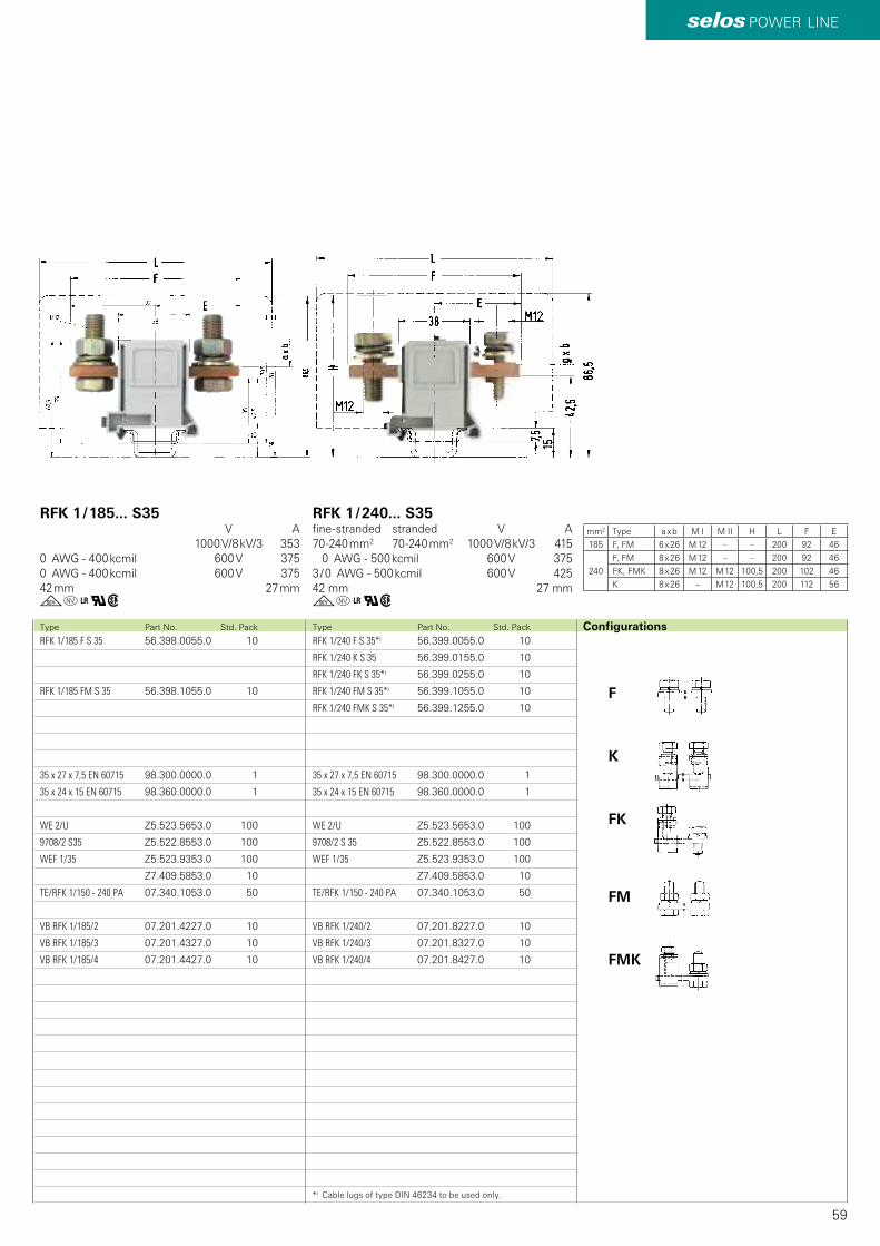
59
selos POWER LINE
RFK 1/240 F S 35*) 56.399.0055.0 10
RFK 1/240 K S 35 56.399.0155.0 10
RFK 1/240 FK S 35*) 56.399.0255.0 10
RFK 1/240 FM S 35*) 56.399.1055.0 10
RFK 1/240 FMK S 35*) 56.399.1255.0 10
35 x 27 x 7,5 EN 60715 98.300.0000.0 1
35 x 24 x 15 EN 60715 98.360.0000.0 1
WE 2/U Z5.523.5653.0 100
9708/2 S 35 Z5.522.8553.0 100
WEF 1/35 Z5.523.9353.0 100
Z7.409.5853.0 10
TE/RFK 1/150 - 240 PA 07.340.1053.0 50
VB RFK 1/240/2 07.201.8227.0 10
VB RFK 1/240/3 07.201.8327.0 10
VB RFK 1/240/4 07.201.8427.0 10
RFK 1/185 F S 35 56.398.0055.0 10
RFK 1/185 FM S 35 56.398.1055.0 10
35 x 27 x 7,5 EN 60715 98.300.0000.0 1
35 x 24 x 15 EN 60715 98.360.0000.0 1
WE 2/U Z5.523.5653.0 100
9708/2 S35 Z5.522.8553.0 100
WEF 1/35 Z5.523.9353.0 100
Z7.409.5853.0 10
TE/RFK 1/150 - 240 PA 07.340.1053.0 50
VB RFK 1/185/2 07.201.4227.0 10
VB RFK 1/185/3 07.201.4327.0 10
VB RFK 1/185/4 07.201.4427.0 10
F
K
FK
FM
FMK
go+qwgo+qw
mm2 a x b M I M II H L F E
185 F, FM 6 x 26 M 12 – – 200 92 46
240
F, FM 8 x 26 M 12 – – 200 92 46
FK, FMK 8 x 26 M 12 M 12 100,5 200 102 46
K 8 x 26 – M 12 100,5 200 112 56
Type Part No. Std. PackType Part No. Std. Pack Configurations
RFK 1 / 240... S35fine-stranded stranded V A70-240 mm2 70-240 mm2 1000 V/8 kV/3 415 0 AWG - 500 kcmil 600 V 3753 / 0 AWG - 500 kcmil 600 V 42542 mm 27 mm
RFK 1 / 185... S35 V A 1000 V/8 kV/3 3530 AWG - 400 kcmil 600 V 3750 AWG - 400 kcmil 600 V 37542 mm 27 mm
*) Cable lugs of type DIN 46234 to be used only.
Type
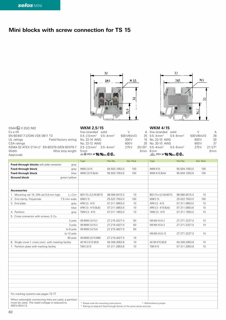
60
selos MINI
WKM 4/15 55.504.1053.0 100
WKM 4/15 BLAU 55.504.1053.6 100
9021/15 x 5,5 EN 60715 98.090.0015.0 10
9208 S 15 Z5.522.7553.0 100
APM 2,5 - 4/15 07.311.0853.0 10
APM 2,5 - 4/15 BLAU 07.311.0853.6 10
TWM 2,5 - 4/15 07.311.1853.0 10
IVB WK 4 E/U-2 Z7.271.2227.0 10
IVB WK 4 E/U-3 Z7.271.2327.0 10
IVB WK 4 E/U-12 Z7.271.3227.0 10
AD VB 4/15 GELB 04.326.2953.8 10
TSM 4/15 07.311.2953.8 10
WKM 2,5/15 55.503.1053.0 100
WKM 2,5/15 BLAU 55.503.1053.6 100
9021/15 x 5,5 EN 60715 98.090.0015.0 10
9208 S 15 Z5.522.7553.0 100
APM 2,5 - 4/15 07.311.0853.0 10
APM 2,5 - 4/15 BLAU 07.311.0853.6 10
TWM 2,5 - 4/15 07.311.1853.0 10
VB WKM 2,5/15-2 Z7.215.4227.0 50
VB WKM 2,5/15-3 Z7.215.4327.0 50
VB WKM 2,5/15-6 Z7.215.4627.0 50
VB WKM 2,5/15 M60 Z7.215.4027.0 10
AD VB 2,5/15 GELB 04.326.3053.8 10
TSM 2,5/15 07.311.2853.8 10
üzC+q#wh gC+q#wh
0344OII 2GD IM2Ex e I/IIEN 60 947-7-2/DIN VDE 0611 T3
KEMA 02 ATEX 2114 U1) EN 60 079-0/EN 60 079-7
Type Part No. Std. PackType Part No. Std. Pack
Mini blocks with screw connection for TS 15
Feed-through blocks with solder connection gray
Feed-through block gray
Feed-through block blue
Ground block green / yellow
Accessories
1. Mounting rail 15, DIN rail 5,5 mm high L = 2 m
2. End clamp, Polyamide 7.5 mm wide
3. End plate gray
blue
4. Partition gray
5. Cross connector with screws, E-Cu
2 pole
3 pole
to 6 pole
to 12 pole
60 pole
6. Single cover f. cross conn. with marking facility
7. Partition plate with marking facility
For marking systems see pages 72-77
When selectable connecting links are used, a partition must be used. The rated voltage is reduced to 400 V / 6 kV / 3.
UL ratings Field / factory wiringCSA ratings
Width Wire strip lengthApprovals
WKM 2,5 / 15fine-stranded solid V A0.5 - 2.5 mm2 0.5 - 4 mm2 500 V/6 kV/3 25No. 22-14 AWG 300 V 10No. 22-12 AWG 600 V 250.5 - 2,5 mm2 0.5 - 4 mm2 275 V 20 / 202)
5 mm 9 mm
WKM 4 / 15fine-stranded solid V A0.5 - 4 mm2 0.5 - 6 mm2 500 V/6 kV/3 28No. 22-10 AWG 600 V 30No. 20-10 AWG 600 V 370.5 - 4 mm2 0.5 - 6 mm2 275 V 21 / 272)
6 mm 9 mm
1) Please note the mounting instructions. 2) With/without jumper3) Ratings to adjacent feed-through blocks of the same series and size.
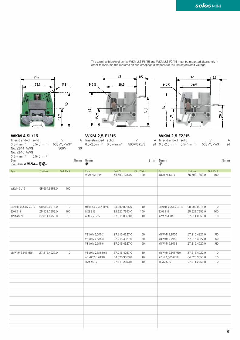
61
selos MINI
WKM 2,5 F2/15 55.503.1353.0 100
9021/15 x 5,5 EN 60715 98.090.0015.0 10
9208 S 15 Z5.522.7553.0 100
APM 2,5 F./15 07.311.0653.0 10
VB WKM 2,5/15-2 Z7.215.4227.0 50
VB WKM 2,5/15-3 Z7.215.4327.0 50
VB WKM 2,5/15-6 Z7.215.4627.0 50
VB WKM 2,5/15 M60 Z7.215.4027.0 10
AD VB 2,5/15 GELB 04.326.3053.8 10
TSM 2,5/15 07.311.2853.8 10
WKM 2,5 F1/15 55.503.1253.0 100
9021/15 x 5,5 EN 60715 98.090.0015.0 10
9208 S 15 Z5.522.7553.0 100
APM 2,5 F./15 07.311.0653.0 10
VB WKM 2,5/15-2 Z7.215.4227.0 50
VB WKM 2,5/15-3 Z7.215.4327.0 50
VB WKM 2,5/15-6 Z7.215.4627.0 50
VB WKM 2,5/15 M60 Z7.215.4027.0 10
AD VB 2,5/15 GELB 04.326.3053.8 10
TSM 2,5/15 07.311.2853.8 10
WKM 4 SL/15 55.504.9153.0 100
9021/15 x 5,5 EN 60715 98.090.0015.0 10
9208 S 15 Z5.522.7553.0 100
APM 4 SL/15 07.311.0753.0 10
VB WKM 2,5/15 M60 Z7.215.4027.0 10
z zgC+q#whType Part No. Std. PackType Part No. Std. PackType Part No. Std. Pack
WKM 2,5 F1 / 15fine-stranded solid V A0.5 - 2.5 mm2 0.5 - 4 mm2 500 V/6 kV/3 24
5 mm 9 mm
WKM 2,5 F2 / 15fine-stranded solid V A0.5 - 2.5 mm2 0.5 - 4 mm2 500 V/6 kV/3 24
5 mm 9 mm
WKM 4 SL / 15 fine-stranded solid V A0.5 - 4 mm2 0.5 - 6 mm2 500 V/6 kV/33)
No. 22-14 AWG 300 V 30No. 22-10 AWG 0.5 - 4 mm2 0.5 - 6 mm2 6 mm 9 mm
The terminal blocks of series WKM 2,5 F1 / 15 and WKM 2,5 F2 / 15 must be mounted alternately in order to maintain the required air and creepage distances for the indicated rated voltage.

62
selos
IVB WK 2,5-2 Z7.280.2227.0 10
IVB WK 2,5-3 Z7.280.2327.0 10
IVB WK 2,5-4 Z7.280.2427.0 10
IVB WK 2,5-12 Z7.280.3227.0 10
IVB WK 4-2 Z7.281.1227.0 10
IVB WK 4-3 Z7.281.1327.0 10
IVB WK 4-4 Z7.281.1427.0 10
IVB WK 4-12 Z7.281.2227.0 10
IVB WK 6-2 Z7.282.2227.0 10
IVB WK 6-3 Z7.282.2327.0 10
IVB WK 6-12 Z7.282.3227.0 10
IVB WKN 10-2 Z7.283.2227.0 10
IVB WKN 10-3 Z7.283.2327.0 10
IVB WKN 10-12 Z7.283.3227.0 10
IVB WKN 16-2 Z7.284.2227.0 10
IVB WKN 16-3 Z7.284.2327.0 10
IVB WKN 16-12 Z7.284.3227.0 10
IVB WKN 16 M-30 Z7.284.2027.0 10
IVB WKN 35-2 Z7.285.2227.0 10
IVB WKN 35-3 Z7.285.2327.0 10
IVB WKN 35-12 Z7.285.3227.0 10
IVB WKN 35 M-20 Z7.285.2027.0 10
VB WK 2,5-2 Z7.280.0227.0 10
VB WK 2,5-3 Z7.280.0327.0 10
VB WK 2,5-6 Z7.280.0627.0 10
VB WK 2,5 M-80 Z7.280.0027.0 10
Z7.280.1027.0 10
VB WK 4-2 Z7.281.0227.0 10
VB WK 4-3 Z7.281.0327.0 10
VB WK 4-6 Z7.281.0627.0 10
VB WK 4 M-70 Z7.281.0027.0 10
Z7.281.1027.0 10
VB WK 6-2 Z7.282.0227.0 10
VB WK 6-3 Z7.282.0327.0 10
VB WK 6-6 Z7.282.0627.0 10
VB WK 6 M-70 Z7.282.0027.0 10
VB WKN 10-2 Z7.283.6227.0 10
VB WKN 10-3 Z7.283.6327.0 10
VB WKN 10-6 Z7.283.6627.0 10
VB WKN 10 M-40 Z7.283.6027.0 10
VB WKN 70-2 Z7.286.3227.0 10
VB WKN 70-3 Z7.286.3327.0 10
VB WKN 70-4 Z7.286.3427.0 10
VB WKN 70-5 Z7.286.3527.0 10
VB WKN 70-6 Z7.286.3627.0 10
VB WKN 150-2 Z7.287.1227.0 5
VB WKN 150-3 Z7.287.1327.0 5
Z7.269.4023.0 50
05.509.6021.0 10
Z7.269.4123.0 50
05.508.8921.0 10
Z7.269.4223.0 50
Accessories for DIN rail terminal blocks with screw connection
Cross connectors, uninsulatedRated voltage reduced to 50 VCross connectors, insulated
Selectable connecting linkWhen selectable connecting links are used, therated voltage is reduced to 380 V!
Type Part No. Std. Pack Type Part No. Std. Pack Type Part No. Std. Pack
WK 2,5 / U, Spacing 5 mm, Screw M2,5
: :
WK 4 / U, Spacing 6 mm, Screw M3
: :
WK 6 / U, Spacing 8 mm, Screw M3,5
: :
WKN 10 / U, Spacing 10 mm, Screw M3,5
: :
WKN 16 / U, Spacing 12 mm, Screw M4
WKN 35 / U, Spacing 16 mm, Screw M5
WKN 70 / U, Spacing 24 mm, Screw M6
WKN 150 / U, Spacing 28 mm, Screw M8
WK 2,5 / U, Spacing 5 mm, Screw M2,5
every 2nd pol (40 pole)
WK 4 / U, Spacing 6 mm, Screw M3
every 2nd pol (30 pole)
WK 6 / U, Spacing 8 mm, Screw M3,5
WKN 10 / U, Spacing 10 mm, Screw M3,5
WKN 16 / U, Spacing 12 mm, Screw M4
WKN 35 / U, Spacing 16 mm, Screw M5
WKN 70 / U, Spacing 24 mm, Screw M6
WKN 150 / U, Spacing 28 mm, Screw M8
WK 2,5 / U, Spacing 5 mm, Screw M2,5
Select. connecting link
Test socket
WK 4 / U, Spacing 6 mm, Screw M3
Select. connecting link
Test socket
WK 6 / U, Spacing 8 mm, Screw M3,5
Select. connecting link
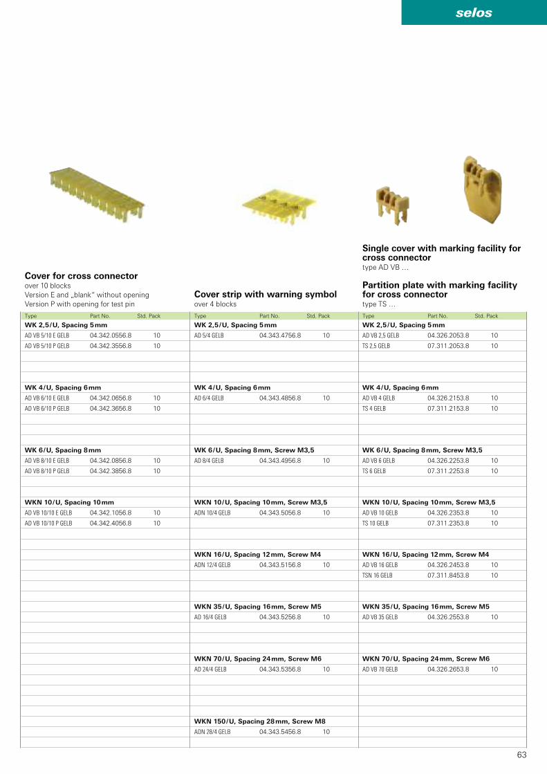
63
selos
AD VB 5/10 E GELB 04.342.0556.8 10
AD VB 5/10 P GELB 04.342.3556.8 10
AD VB 6/10 E GELB 04.342.0656.8 10
AD VB 6/10 P GELB 04.342.3656.8 10
AD VB 8/10 E GELB 04.342.0856.8 10
AD VB 8/10 P GELB 04.342.3856.8 10
AD VB 10/10 E GELB 04.342.1056.8 10
AD VB 10/10 P GELB 04.342.4056.8 10
AD 5/4 GELB 04.343.4756.8 10
AD 6/4 GELB 04.343.4856.8 10
AD 8/4 GELB 04.343.4956.8 10
ADN 10/4 GELB 04.343.5056.8 10
ADN 12/4 GELB 04.343.5156.8 10
AD 16/4 GELB 04.343.5256.8 10
AD 24/4 GELB 04.343.5356.8 10
ADN 28/4 GELB 04.343.5456.8 10
AD VB 2,5 GELB 04.326.2053.8 10
TS 2,5 GELB 07.311.2053.8 10
AD VB 4 GELB 04.326.2153.8 10
TS 4 GELB 07.311.2153.8 10
AD VB 6 GELB 04.326.2253.8 10
TS 6 GELB 07.311.2253.8 10
AD VB 10 GELB 04.326.2353.8 10
TS 10 GELB 07.311.2353.8 10
AD VB 16 GELB 04.326.2453.8 10
TSN 16 GELB 07.311.8453.8 10
AD VB 35 GELB 04.326.2553.8 10
AD VB 70 GELB 04.326.2653.8 10
Cover strip with warning symbolover 4 blocks
Cover for cross connectorover 10 blocks Version E and „blank“ without openingVersion P with opening for test pin
Single cover with marking facility for cross connectortype AD VB …
Partition plate with marking facility for cross connectortype TS …
Type Part No. Std. Pack Type Part No. Std. PackType Part No. Std. Pack
WK 2,5 / U, Spacing 5 mm
WK 4 / U, Spacing 6 mm
WK 6 / U, Spacing 8 mm
WKN 10 / U, Spacing 10 mm
WK 2,5 / U, Spacing 5 mm
WK 4 / U, Spacing 6 mm
WK 6 / U, Spacing 8 mm, Screw M3,5
WKN 10 / U, Spacing 10 mm, Screw M3,5
WKN 16 / U, Spacing 12 mm, Screw M4
WKN 35 / U, Spacing 16 mm, Screw M5
WKN 70 / U, Spacing 24 mm, Screw M6
WKN 150 / U, Spacing 28 mm, Screw M8
WK 2,5 / U, Spacing 5 mm
WK 4 / U, Spacing 6 mm
WK 6 / U, Spacing 8 mm, Screw M3,5
WKN 10 / U, Spacing 10 mm, Screw M3,5
WKN 16 / U, Spacing 12 mm, Screw M4
WKN 35 / U, Spacing 16 mm, Screw M5
WKN 70 / U, Spacing 24 mm, Screw M6
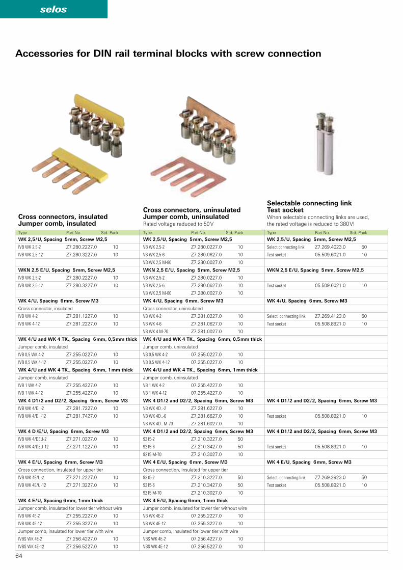
64
selos
IVB WK 2,5-2 Z7.280.2227.0 10
IVB WK 2,5-12 Z7.280.3227.0 10
IVB WK 2,5-2 Z7.280.2227.0 10
IVB WK 2,5-12 Z7.280.3227.0 10
IVB WK 4-2 Z7.281.1227.0 10
IVB WK 4-12 Z7.281.2227.0 10
IVB 0,5 WK 4-2 Z7.255.0227.0 10
IVB 0,5 WK 4-12 Z7.255.0227.0 10
IVB 1 WK 4-2 Z7.255.4227.0 10
IVB 1 WK 4-12 Z7.255.4227.0 10
IVB WK 4/D..-2 Z7.281.7227.0 10
IVB WK 4/D..-12 Z7.281.7427.0 10
IVB WK 4/DEU-2 Z7.271.0227.0 10
IVB WK 4/DEU-12 Z7.271.1227.0 10
IVB WK 4E/U-2 Z7.271.2227.0 10
IVB WK 4E/U-12 Z7.271.3227.0 10
IVB WK 4E-2 Z7.255.2227.0 10
IVB WK 4E-12 Z7.255.3227.0 10
IVBS WK 4E-2 Z7.256.4227.0 10
IVBS WK 4E-12 Z7.256.5227.0 10
VB WK 2,5-2 Z7.280.0227.0 10
VB WK 2,5-6 Z7.280.0627.0 10
VB WK 2,5 M-80 Z7.280.0027.0 10
VB WK 2,5-2 Z7.280.0227.0 10
VB WK 2,5-6 Z7.280.0627.0 10
VB WK 2,5 M-80 Z7.280.0027.0 10
VB WK 4-2 Z7.281.0227.0 10
VB WK 4-6 Z7.281.0627.0 10
VB WK 4 M-70 Z7.281.0027.0 10
VB 0,5 WK 4-2 07.255.0227.0 10
VB 0,5 WK 4-12 07.255.0227.0 10
VB 1 WK 4-2 07.255.4227.0 10
VB 1 WK 4-12 07.255.4227.0 10
VB WK 4D..-2 Z7.281.6227.0 10
VB WK 4D..-6 Z7.281.6627.0 10
VB WK 4D.. M-70 Z7.281.6027.0 10
9215-2 Z7.210.3227.0 50
9215-6 Z7.210.3427.0 50
9215 M-70 Z7.210.3027.0 10
9215-2 Z7.210.3227.0 50
9215-6 Z7.210.3427.0 50
9215 M-70 Z7.210.3027.0 10
VB WK 4E-2 07.255.2227.0 10
VB WK 4E-12 07.255.3227.0 10
VBS WK 4E-2 07.256.4227.0 10
VBS WK 4E-12 07.256.5227.0 10
Z7.269.4023.0 50
05.509.6021.0 10
05.509.6021.0 10
Z7.269.4123.0 50
05.508.8921.0 10
05.508.8921.0 10
05.508.8921.0 10
Z7.269.2923.0 50
05.508.8921.0 10
Accessories for DIN rail terminal blocks with screw connection
Cross connectors, uninsulatedJumper comb, uninsulatedRated voltage reduced to 50 V
Cross connectors, insulatedJumper comb, insulated
Selectable connecting linkTest socketWhen selectable connecting links are used,the rated voltage is reduced to 380 V!
Type Part No. Std. Pack Type Part No. Std. Pack Type Part No. Std. Pack
WK 2,5 / U, Spacing 5 mm, Screw M2,5
WKN 2,5 E / U, Spacing 5 mm, Screw M2,5
WK 4 / U, Spacing 6 mm, Screw M3
Cross connector, insulated
WK 4 / U and WK 4 TK., Spacing 6 mm, 0,5 mm thick
Jumper comb, insulated
WK 4 / U and WK 4 TK., Spacing 6 mm, 1 mm thick
Jumper comb, insulated
WK 4 D1 / 2 and D2 / 2, Spacing 6mm, Screw M3
WK 4 D /E / U, Spacing 6 mm, Screw M3
WK 4 E / U, Spacing 6 mm, Screw M3
Cross connection, insulated for upper tier
WK 4 E / U, Spacing 6 mm, 1 mm thick
Jumper comb, insulated for lower tier without wire
Jumper comb, insulated for lower tier with wire
WK 2,5 / U, Spacing 5 mm, Screw M2,5
WKN 2,5 E / U, Spacing 5 mm, Screw M2,5
WK 4 / U, Spacing 6 mm, Screw M3
Cross connector, uninsulated
WK 4 / U and WK 4 TK., Spacing 6 mm, 0,5 mm thick
Jumper comb, uninsulated
WK 4 / U and WK 4 TK., Spacing 6 mm, 1 mm thick
Jumper comb, uninsulated
WK 4 D1 / 2 and D2 / 2, Spacing 6 mm, Screw M3
WK 4 D1 / 2 and D2 / 2, Spacing 6 mm, Screw M3
WK 4 E / U, Spacing 6 mm, Screw M3
Cross connection, insulated for upper tier
WK 4 E / U, Spacing 6 mm, 1 mm thick
Jumper comb, insulated for lower tier without wire
Jumper comb, insulated for lower tier with wire
WK 2,5 / U, Spacing 5 mm, Screw M2,5
Select.connecting link
Test socket
WKN 2,5 E / U, Spacing 5 mm, Screw M2,5
Test socket
WK 4 / U, Spacing 6 mm, Screw M3
Select. connecting link
Test socket
WK 4 D1 / 2 and D2 / 2, Spacing 6 mm, Screw M3
Test socket
WK 4 D1 / 2 and D2 / 2, Spacing 6 mm, Screw M3
Test socket
WK 4 E / U, Spacing 6 mm, Screw M3
Select. connecting link
Test socket
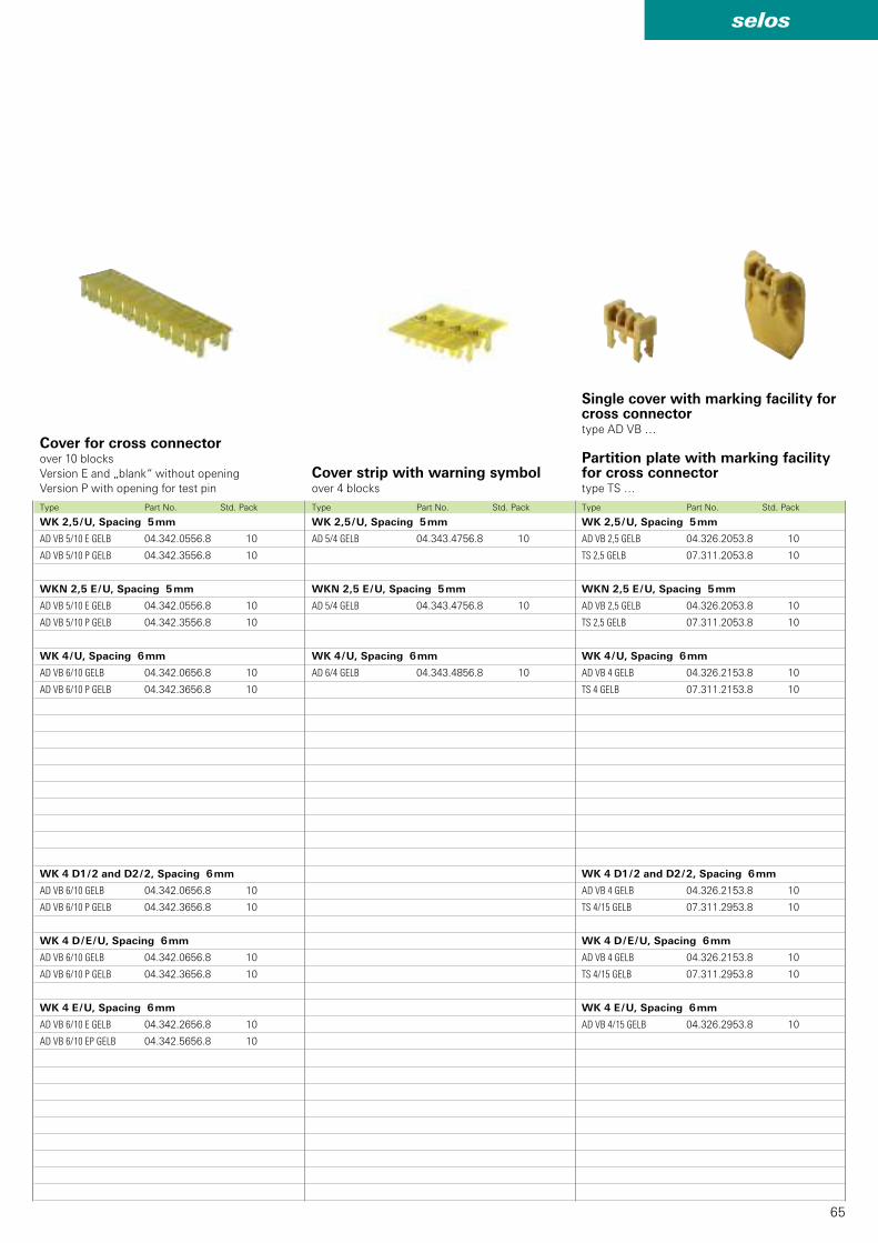
65
selos
AD VB 5/10 E GELB 04.342.0556.8 10
AD VB 5/10 P GELB 04.342.3556.8 10
AD VB 5/10 E GELB 04.342.0556.8 10
AD VB 5/10 P GELB 04.342.3556.8 10
AD VB 6/10 GELB 04.342.0656.8 10
AD VB 6/10 P GELB 04.342.3656.8 10
AD VB 6/10 GELB 04.342.0656.8 10
AD VB 6/10 P GELB 04.342.3656.8 10
AD VB 6/10 GELB 04.342.0656.8 10
AD VB 6/10 P GELB 04.342.3656.8 10
AD VB 6/10 E GELB 04.342.2656.8 10
AD VB 6/10 EP GELB 04.342.5656.8 10
AD 5/4 GELB 04.343.4756.8 10
AD 5/4 GELB 04.343.4756.8 10
AD 6/4 GELB 04.343.4856.8 10
AD VB 2,5 GELB 04.326.2053.8 10
TS 2,5 GELB 07.311.2053.8 10
AD VB 2,5 GELB 04.326.2053.8 10
TS 2,5 GELB 07.311.2053.8 10
AD VB 4 GELB 04.326.2153.8 10
TS 4 GELB 07.311.2153.8 10
AD VB 4 GELB 04.326.2153.8 10
TS 4/15 GELB 07.311.2953.8 10
AD VB 4 GELB 04.326.2153.8 10
TS 4/15 GELB 07.311.2953.8 10
AD VB 4/15 GELB 04.326.2953.8 10
Cover strip with warning symbolover 4 blocks
Cover for cross connectorover 10 blocks Version E and „blank“ without openingVersion P with opening for test pin
Single cover with marking facility for cross connectortype AD VB …
Partition plate with marking facility for cross connectortype TS …
Type Part No. Std. Pack Type Part No. Std. PackType Part No. Std. Pack
WK 2,5 / U, Spacing 5 mm
WKN 2,5 E / U, Spacing 5 mm
WK 4 / U, Spacing 6 mm
WK 4 D1 / 2 and D2 / 2, Spacing 6 mm
WK 4 D / E / U, Spacing 6 mm
WK 4 E / U, Spacing 6 mm
WK 2,5 / U, Spacing 5 mm
WKN 2,5 E / U, Spacing 5 mm
WK 4 / U, Spacing 6 mm
WK 2,5 / U, Spacing 5 mm
WKN 2,5 E / U, Spacing 5 mm
WK 4 / U, Spacing 6 mm
WK 4 D1 / 2 and D2 / 2, Spacing 6 mm
WK 4 D / E / U, Spacing 6 mm
WK 4 E / U, Spacing 6 mm
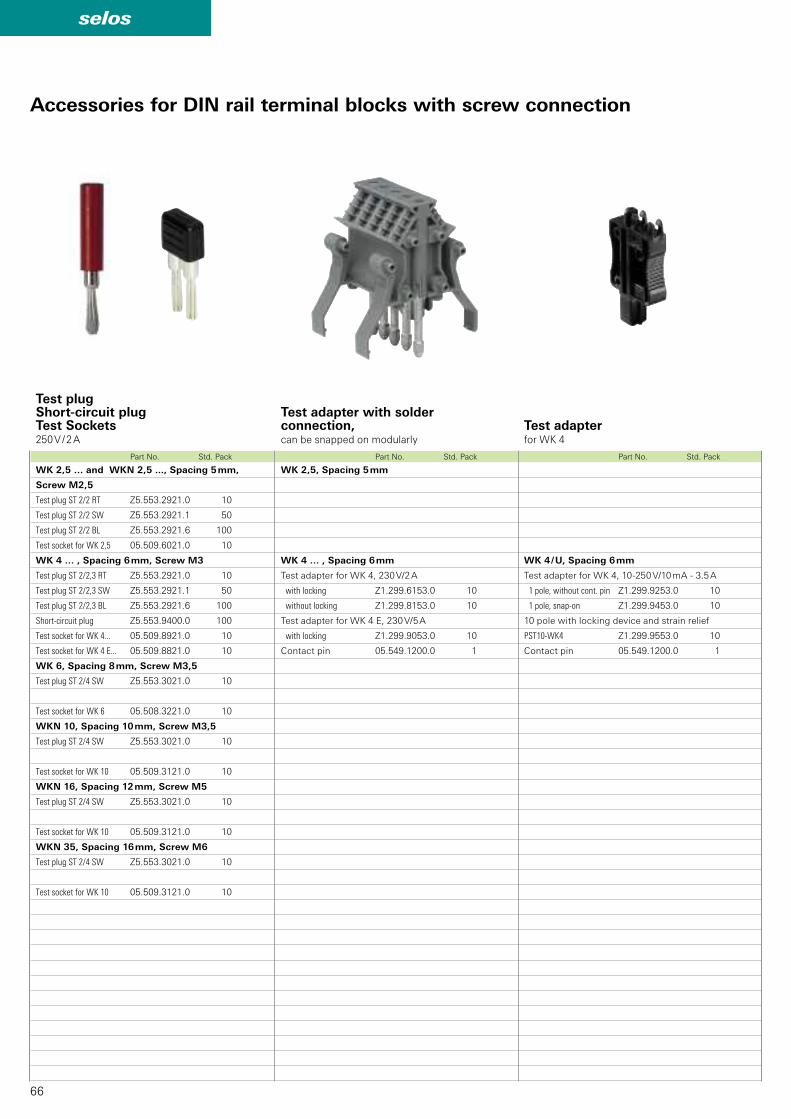
66
selos
Z5.553.2921.0 10
Z5.553.2921.1 50
Z5.553.2921.6 100
05.509.6021.0 10
Z5.553.2921.0 10
Z5.553.2921.1 50
Z5.553.2921.6 100
Z5.553.9400.0 100
05.509.8921.0 10
05.509.8821.0 10
Z5.553.3021.0 10
05.508.3221.0 10
Z5.553.3021.0 10
05.509.3121.0 10
Z5.553.3021.0 10
05.509.3121.0 10
Z5.553.3021.0 10
05.509.3121.0 10
Z1.299.6153.0 10
Z1.299.8153.0 10
Z1.299.9053.0 10
05.549.1200.0 1
Z1.299.9253.0 10
Z1.299.9453.0 10
PST10-WK4 Z1.299.9553.0 10
05.549.1200.0 1
Test adapter with solderconnection, can be snapped on modularly
Test plugShort-circuit plugTest Sockets250 V / 2 A
Test adapter for WK 4
Accessories for DIN rail terminal blocks with screw connection
Part No. Std. Pack Part No. Std. Pack Part No. Std. Pack
WK 2,5 … and WKN 2,5 ..., Spacing 5 mm,
Screw M2,5
Test plug ST 2/2 RT
Test plug ST 2/2 SW
Test plug ST 2/2 BL
Test socket for WK 2,5
WK 4 … , Spacing 6 mm, Screw M3
Test plug ST 2/2,3 RT
Test plug ST 2/2,3 SW
Test plug ST 2/2,3 BL
Short-circuit plug
Test socket for WK 4...
Test socket for WK 4 E...
WK 6, Spacing 8 mm, Screw M3,5
Test plug ST 2/4 SW
Test socket for WK 6
WKN 10, Spacing 10 mm, Screw M3,5
Test plug ST 2/4 SW
Test socket for WK 10
WKN 16, Spacing 12 mm, Screw M5
Test plug ST 2/4 SW
Test socket for WK 10
WKN 35, Spacing 16 mm, Screw M6
Test plug ST 2/4 SW
Test socket for WK 10
WK 2,5, Spacing 5 mm
WK 4 … , Spacing 6 mm
Test adapter for WK 4, 230 V/2 A
with locking
without locking
Test adapter for WK 4 E, 230 V/5 A
with locking
Contact pin
WK 4 / U, Spacing 6 mm
Test adapter for WK 4, 10-250 V/10 mA - 3.5 A
1 pole, without cont. pin
1 pole, snap-on
10 pole with locking device and strain relief
Contact pin
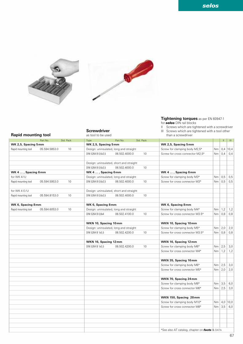
67
selos
05.594.5853.0 10
05.594.5953.0 10
05.594.8153.0 10
05.594.6053.0 10
DIN 5264 B 0,6x3,5 06.502.4000.0 10
DIN 5264 B 0,6x3,5 06.502.4000.0 10
DIN 5264 B 0,6x3,5 06.502.4000.0 10
DIN 5264 B 0,6x3,5 06.502.4000.0 10
DIN 5264 B 0,8x4 06.502.4100.0 10
DIN 5264 B 1x5,5 06.502.4200.0 10
DIN 5264 B 1x5,5 06.502.4200.0 10
Nm 0,4 10,4
Nm 0,4 0,4
Nm 0,5 0,5
Nm 0,5 0,5
Nm 1,2 1,2
Nm 0,8 0,8
Nm 2,0 2,0
Nm 0,8 0,8
Nm 2,5 3,0
Nm 1,2 1,2
Nm 2,5 3,0
Nm 2,0 2,0
Nm 3,5 6,0
Nm 2,5 3,0
Nm 4,0 10,0
Nm 3,5 6,0
Screwdriver as tool to be usedRapid mounting tool
Tightening torques as per EN 60947-1for selos DIN rail blocksII Screws which are tightened with a screwdriverIII Screws which are tightened with a tool other
than a screwdriver
Type Part No. Std. Pack II III Part No. Std. Pack
WK 2,5, Spacing 5 mm
Screw for clamping body M2,5*
Screw for cross connector M2,5*
WK 4 … , Spacing 6 mm
Screw for clamping body M3*
Screw for cross connector M3*
WK 6, Spacing 8 mm
Screw for clamping body M4*
Screw for cross connector M3.5*
WKN 10, Spacing 10 mm
Screw for clamping body M5*
Screw for cross connector M3.5*
WKN 16, Spacing 12 mm
Screw for clamping body M6*
Screw for cross connector M4*
WKN 35, Spacing 16 mm
Screw for clamping body M6*
Screw for cross connector M5*
WKN 70, Spacing 24 mm
Screw for clamping body M8*
Screw for cross connector M6*
WKN 150, Spacing 28 mm
Screw for clamping body M10*
Screw for cross connector M8*
*See also AT catalog, chapter on facts & DATA
WK 2,5, Spacing 5 mm
Rapid mounting tool
WK 4 … , Spacing 6 mm
for WK 4 / U
Rapid mounting tool
for WK 4 E / U
Rapid mounting tool
WK 6, Spacing 8 mm
Rapid mounting tool
WK 2,5, Spacing 5 mm
Design: uninsulated, long and straight
Design: uninsulated, short and straight
WK 4 … , Spacing 6 mm
Design: uninsulated, long and straight
Design: uninsulated, short and straight
WK 6, Spacing 8 mm
Design: uninsulated, long and straight
WKN 10, Spacing 10 mm
Design: uninsulated, long and straight
WKN 16, Spacing 12 mm
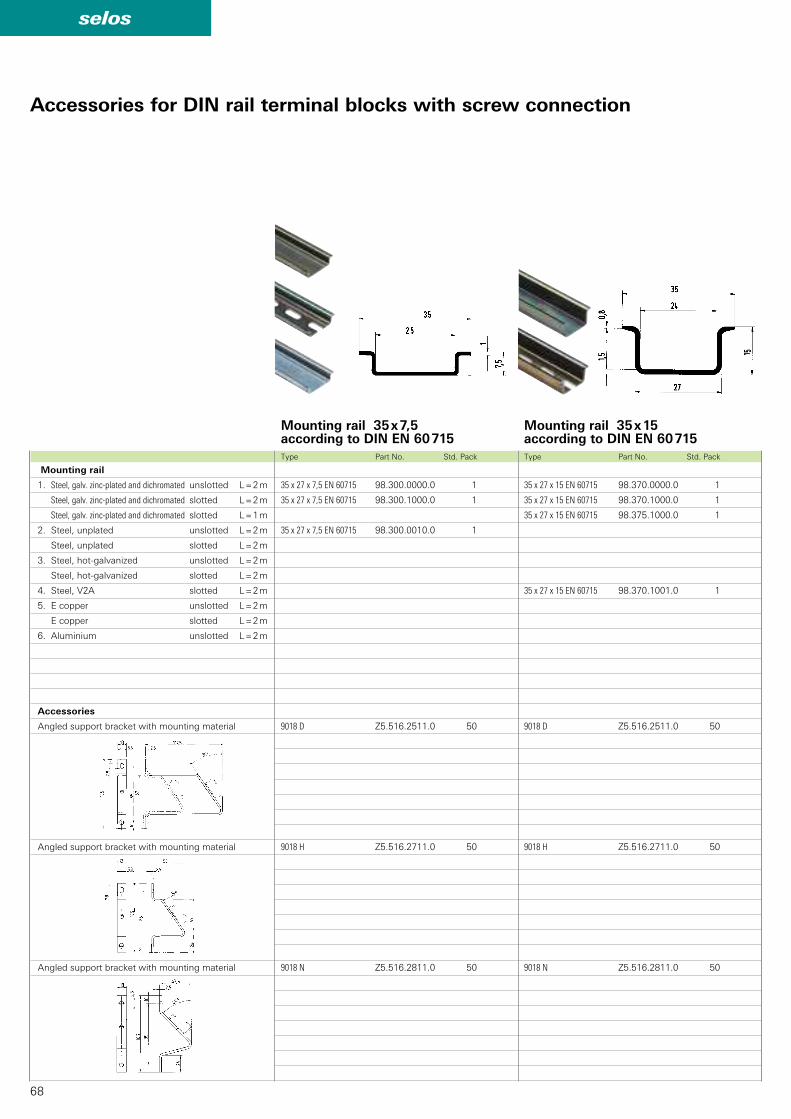
68
selos
35 x 27 x 15 EN 60715 98.370.0000.0 1
35 x 27 x 15 EN 60715 98.370.1000.0 1
35 x 27 x 15 EN 60715 98.375.1000.0 1
35 x 27 x 15 EN 60715 98.370.1001.0 1
9018 D Z5.516.2511.0 50
9018 H Z5.516.2711.0 50
9018 N Z5.516.2811.0 50
35 x 27 x 7,5 EN 60715 98.300.0000.0 1
35 x 27 x 7,5 EN 60715 98.300.1000.0 1
35 x 27 x 7,5 EN 60715 98.300.0010.0 1
9018 D Z5.516.2511.0 50
9018 H Z5.516.2711.0 50
9018 N Z5.516.2811.0 50
Mounting rail
1. Steel, galv. zinc-plated and dichromated unslotted L = 2 m
Steel, galv. zinc-plated and dichromated slotted L = 2 m
Steel, galv. zinc-plated and dichromated slotted L = 1 m
2. Steel, unplated unslotted L = 2 m
Steel, unplated slotted L = 2 m
3. Steel, hot-galvanized unslotted L = 2 m
Steel, hot-galvanized slotted L = 2 m
4. Steel, V2A slotted L = 2 m
5. E copper unslotted L = 2 m
E copper slotted L = 2 m
6. Aluminium unslotted L = 2 m
Accessories
Angled support bracket with mounting material
Angled support bracket with mounting material
Angled support bracket with mounting material
Accessories for DIN rail terminal blocks with screw connection
Mounting rail 35 x 7,5according to DIN EN 60 715
Mounting rail 35 x 15according to DIN EN 60 715
Type Part No. Std. Pack Type Part No. Std. Pack
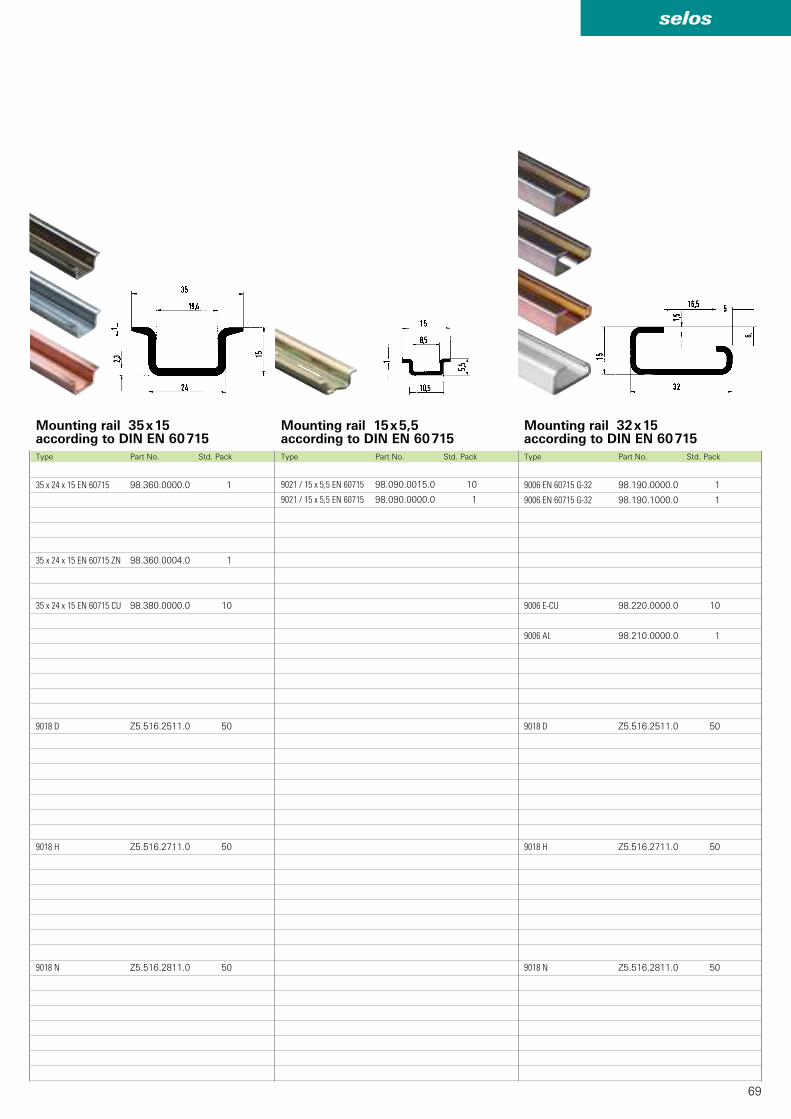
69
selos
9021 / 15 x 5,5 EN 60715 98.090.0015.0 10
9021 / 15 x 5,5 EN 60715 98.090.0000.0 1
35 x 24 x 15 EN 60715 98.360.0000.0 1
35 x 24 x 15 EN 60715 ZN 98.360.0004.0 1
35 x 24 x 15 EN 60715 CU 98.380.0000.0 10
9018 D Z5.516.2511.0 50
9018 H Z5.516.2711.0 50
9018 N Z5.516.2811.0 50
9006 EN 60715 G-32 98.190.0000.0 1
9006 EN 60715 G-32 98.190.1000.0 1
9006 E-CU 98.220.0000.0 10
9006 AL 98.210.0000.0 1
9018 D Z5.516.2511.0 50
9018 H Z5.516.2711.0 50
9018 N Z5.516.2811.0 50
Mounting rail 35 x 15according to DIN EN 60 715
Type Part No. Std. PackType Part No. Std. Pack Type Part No. Std. Pack
Mounting rail 15 x 5,5according to DIN EN 60 715
Mounting rail 32 x 15according to DIN EN 60 715

70
selos
WEF 1 /35 Z5.523.9353.0 100
WEF 1 BS /35 69.920.1053.0 100
WEF 1 BSS /35 69.920.1253.0 100
BS/R 69.920.1053.0 10
04.019.0289.0 10
04.243.8550.0 10
04.019.1189.0 10
WEF 2 /35 Z5.523.9453.0 100
Accessories for DIN rail terminal blocks with screw connection
End clamp for TS 35no-screw mounting
End clamp for TS 35no-screw mounting
End clamp
1. End clamp TS 35 without screws 5 mm wide
2. End clamp TS 35 without screws 8 mm wide
3. End clamp TS 35 without screws 17.5 mm wide
with marking facilities
4. End clamp TS 35 without screws 8 mm wide
with marking facilities
5. End clamp TS 35 with screws 8 mm wide
6. End clamp TS 35 with screws 17.5 mm wide
with marking facilities
7. End clamp TS 15 with screws 7.5 mm wide
End clamp, steel (without picture) 5 mm wide
8. End clamp with U-foot 10 mm wide
9. End clamp with U-foot 17.5 mm wide
with marking facilities
10. End clamp with U-foot 10 mm wide
11. End clamp with U-foot 17.5 mm wide
with marking facilities
Accessories
Marking tag for WEF 1 / 35 wide
Marking cardboard in perforated sheets 100 tags / sheet
Marking tag for WEF 1 / 35 small
Marking cardboard in perforated sheets small
Type Part No. Std. Pack Type Part No. Std. Pack
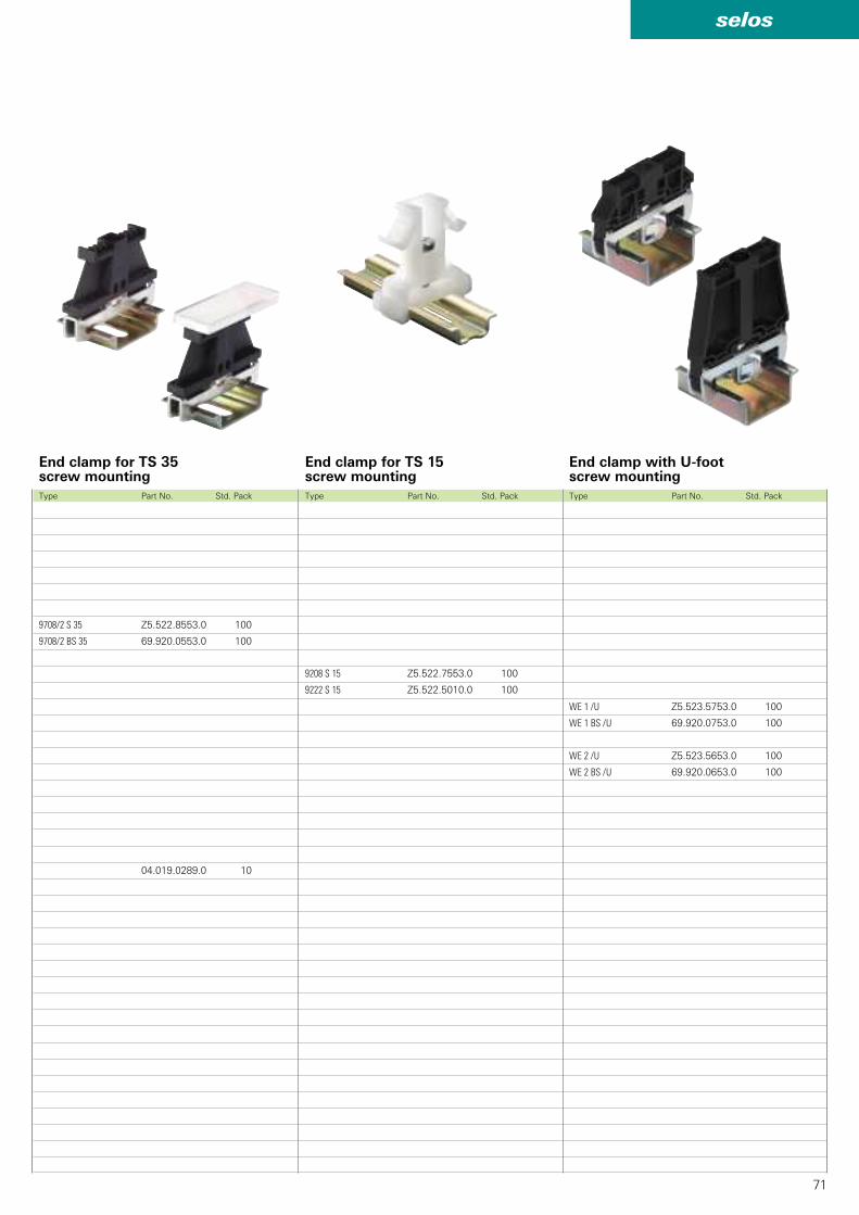
71
selos
9208 S 15 Z5.522.7553.0 100
9222 S 15 Z5.522.5010.0 100
9708/2 S 35 Z5.522.8553.0 100
9708/2 BS 35 69.920.0553.0 100
04.019.0289.0 10
WE 1 /U Z5.523.5753.0 100
WE 1 BS /U 69.920.0753.0 100
WE 2 /U Z5.523.5653.0 100
WE 2 BS /U 69.920.0653.0 100
End clamp for TS 35screw mounting
End clamp for TS 15screw mounting
Type Part No. Std. PackType Part No. Std. Pack Type Part No. Std. Pack
End clamp with U-footscrew mounting
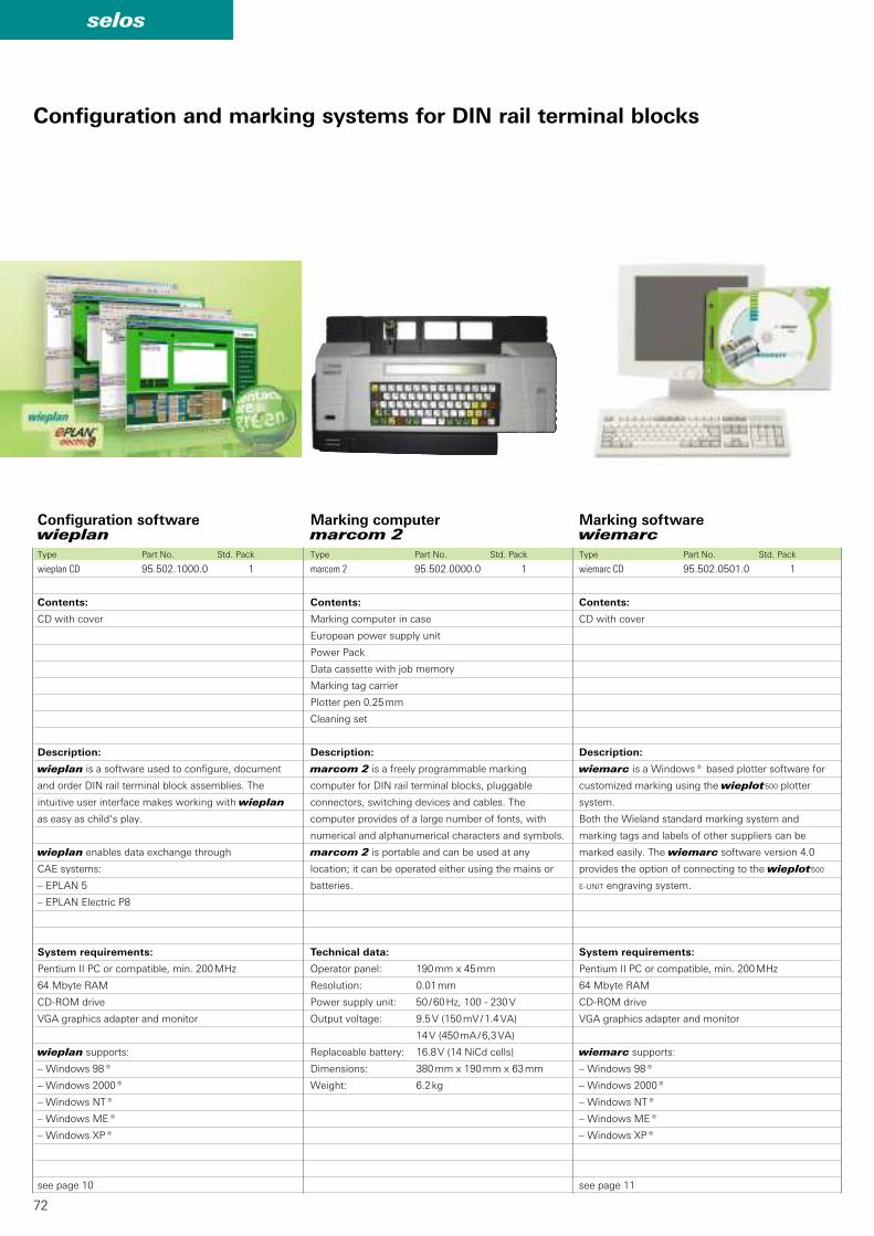
72
selos
wieplan CD 95.502.1000.0 1 marcom 2 95.502.0000.0 1 wiemarc CD 95.502.0501.0 1
Marking computermarcom 2
Marking software wiemarc
Type Part No. Std. Pack Type Part No. Std. PackType Part No. Std. Pack
Configuration softwarewieplan
Contents:
CD with cover
Description:
wieplan is a software used to configure, document
and order DIN rail terminal block assemblies. The
intuitive user interface makes working with wieplan
as easy as child‘s play.
wieplan enables data exchange through
CAE systems:
– EPLAN 5
– EPLAN Electric P8
System requirements:
Pentium II PC or compatible, min. 200 MHz
64 Mbyte RAM
CD-ROM drive
VGA graphics adapter and monitor
wieplan supports:
– Windows 98®
– Windows 2000®
– Windows NT®
– Windows ME®
– Windows XP®
see page 10
Contents:
Marking computer in case
European power supply unit
Power Pack
Data cassette with job memory
Marking tag carrier
Plotter pen 0.25 mm
Cleaning set
Description:
marcom 2 is a freely programmable marking
computer for DIN rail terminal blocks, pluggable
connectors, switching devices and cables. The
computer provides of a large number of fonts, with
numerical and alphanumerical characters and symbols.
marcom 2 is portable and can be used at any
location; it can be operated either using the mains or
batteries.
Technical data:
Operator panel: 190 mm x 45 mm
Resolution: 0.01 mm
Power supply unit: 50 / 60 Hz, 100 - 230 V
Output voltage: 9.5 V (150 mV / 1.4 VA)
14 V (450 mA / 6,3 VA)
Replaceable battery: 16.8 V (14 NiCd cells)
Dimensions: 380 mm x 190 mm x 63 mm
Weight: 6.2 kg
Contents:
CD with cover
Description:
wiemarc is a Windows® based plotter software for
customized marking using the wieplot 500 plotter
system.
Both the Wieland standard marking system and
marking tags and labels of other suppliers can be
marked easily. The wiemarc software version 4.0
provides the option of connecting to the wieplot 500
E-UNIT engraving system.
System requirements:
Pentium II PC or compatible, min. 200 MHz
64 Mbyte RAM
CD-ROM drive
VGA graphics adapter and monitor
wiemarc supports:
– Windows 98®
– Windows 2000®
– Windows NT®
– Windows ME®
– Windows XP®
see page 11
Configuration and marking systems for DIN rail terminal blocks
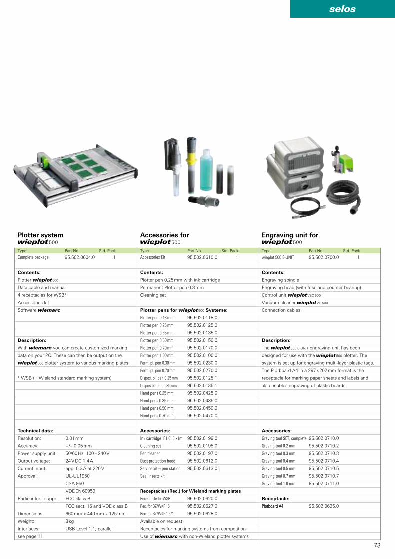
73
selos
95.502.0604.0 1 95.502.0610.0 1 wieplot 500 E-UNIT 95.502.0700.0 1
95.502.0118.0
95.502.0125.0
95.502.0135.0
95.502.0150.0
95.502.0170.0
95.502.0100.0
95.502.0230.0
95.502.0270.0
95.502.0125.1
95.502.0135.1
95.502.0425.0
95.502.0435.0
95.502.0450.0
95.502.0470.0
95.502.0199.0
95.502.0198.0
95.502.0197.0
95.502.0612.0
95.502.0613.0
95.502.0620.0
95.502.0627.0
95.502.0628.0
95.502.0710.0
95.502.0710.2
95.502.0710.3
95.502.0710.4
95.502.0710.5
95.502.0710.7
95.502.0711.0
Plotboard A4 95.502.0625.0
Plotter system wieplot 500
Accessories for wieplot 500
Engraving unit for wieplot 500
Type Part No. Std. PackType Part No. Std. Pack Type Part No. Std. Pack
Contents:
Plotter wieplot 500
Data cable and manual
4 receptacles for WSB*
Accessories kit
Software wiemarc
Description:
With wiemarc you can create customized marking
data on your PC. These can then be output on the
wieplot 500 plotter system to various marking plates.
* WSB (= Wieland standard marking system)
Technical data:
Resolution: 0.01 mm
Accuracy: +/– 0.05 mm
Power supply unit: 50/60 Hz, 100 - 240 V
Output voltage: 24 V DC 1.4 A
Current input: app. 0,3 A at 220 V
Approval: UL-UL1950
CSA 950
VDE EN 60950
Radio interf. suppr.: FCC class B
FCC sect. 15 and VDE class B
Dimensions: 660 mm x 440 mm x 125 mm
Weight: 8 kg
Interfaces: USB Level 1.1, parallel
see page 11
Contents:
Plotter pen 0,25 mm with ink cartridge
Permanent Plotter pen 0.3 mm
Cleaning set
Accessories:
Ink cartridge P1.0, 5 x1ml
Cleaning set
Pen cleaner
Dust protection hood
Service kit – pen station
Seal inserts kit
Receptacles (Rec.) for Wieland marking plates
Receptacle for WSB
Rec. for BZ/WKF 15,
Rec. for BZ/WKF 1,5/10
Available on request:
Receptacles for marking systems from competition
Use of wiemarc with non-Wieland plotter systems
Contents:
Engraving spindle
Engraving head (with fuse and counter bearing)
Control unit wieplot VEC 500
Vacuum cleaner wieplot VC 500
Connection cables
Description:
The wieplot 500 E-UNIT engraving unit has been
designed for use with the wieplot 500 plotter. The
system is set up for engraving multi-layer plastic tags.
The Plotboard A4 in a 297 x 202 mm format is the
receptacle for marking paper sheets and labels and
also enables engraving of plastic boards.
Accessories:
Receptacle:
Plotter pens for wieplot 500 Systeme:
Plotter pen 0.18 mm
Plotter pen 0.25 mm
Plotter pen 0.35 mm
Plotter pen 0.50 mm
Plotter pen 0.70 mm
Plotter pen 1.00 mm
Perm. pl. pen 0.30 mm
Perm. pl. pen 0.70 mm
Dispos. pl. pen 0.25 mm
Dispos.pl. pen 0.35 mm
Hand pens 0.25 mm
Hand pens 0.35 mm
Hand pens 0.50 mm
Hand pens 0.70 mm
Complete package Accessories Kit
Plotboard A4
Graving tool SET, complete
Graving tool 0.2 mm
Graving tool 0.3 mm
Graving tool 0.4 mm
Graving tool 0.5 mm
Graving tool 0.7 mm
Graving tool 1.0 mm
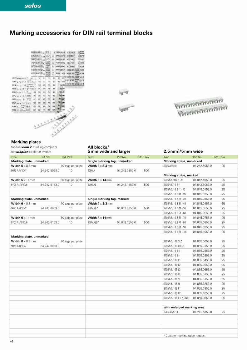
74
selos
9075 A/5/10/11 Z4.242.5053.0 10
9705 AL/5/10/6 Z4.242.5153.0 10
9075 A/6/10/11 Z4.242.6053.0 10
9705 AL/6/10/6 Z4.242.6153.0 10
9075 A/8/10/7 Z4.242.8053.0 10
9705 A 04.242.0850.0 500
9705 AL 04.242.1553.0 500
9705 AB 04.842.0850.0 500
9705 ALB 04.842.1553.0 500
9705 A/5/10 04.242.5053.0 25
9705A/5/9 B 1 - 9 04.842.4953.0 25
9705A/5/10 B 04.842.5053.0 25
9705A/5/10 B 1 - 10 04.845.0153.0 25
9705A/5/10 B 11 - 20 04.845.0253.0 25
9705A/5/10 B 21 - 30 04.845.0353.0 25
9705A/5/10 B 31 - 40 04.845.0453.0 25
9705A/5/10 B 41 - 50 04.845.0553.0 25
9705A/5/10 B 51 - 60 04.845.0653.0 25
9705A/5/10 B 61 - 70 04.845.0753.0 25
9705A/5/10 B 71 - 80 04.845.0853.0 25
9705A/5/10 B 81 - 90 04.845.0953.0 25
9705A/5/10 B 91 - 100 04.845.1053.0 25
9705A/5/10B SLZ 04.855.0053.0 25
9705A/5/10B ERDZ 04.855.0153.0 25
9705A/5/10 B + 04.855.0253.0 25
9705A/5/10 B - 04.855.0353.0 25
9705A/5/10B L1 04.855.0453.0 25
9705A/5/10B L2 04.855.0553.0 25
9705A/5/10B L3 04.855.0653.0 25
9705A/5/10B PE 04.855.0753.0 25
9705A/5/10B SL 04.855.3153.0 25
9705A/5/10B N 04.855.3253.0 25
9705A/5/10B F1 04.855.0953.0 25
9705A/5/10B F2 04.855.1053.0 25
9705A/5/10B L1L2L3NPE.. 04.855.0853.0 25
9705 AL/5/10 04.242.5153.0 25
Marking plates for marcom 2 marking computer
for wieplot 500 plotter system
All blocks /5 mm wide and larger
Type Part No. Std. Pack Type Part No. Std. Pack
Marking plate, unmarked
Width 5 x 8.3 mm 110 tags per plate
Width 5 x 14 mm 60 tags per plate
Marking plate, unmarked
Width 6 x 8.3 mm 110 tags per plate
Width 6 x 14 mm 60 tags per plate
Marking plate, unmarked
Width 8 x 8.3 mm 70 tags per plate
Single marking tag, unmarked
Width 5 x 8.3 mm
Width 5 x 14 mm
Single marking tag, marked
Width 5 x 8.3 mm
*
Width 5 x 14 mm
*
Marking accessories for DIN rail terminal blocks
2.5 mm2 / 5 mm wide
Type Part No. Std. Pack
Marking strips, unmarked
Marking strips, marked
*
with enlarged marking area
* Custom marking upon request

75
selos
9705 A/5/10/5 B 04.842.5553.0 25
9705 A/6/10 04.242.6053.0 25
9705A/6/9 B 1 - 9 04.842.5953.0 25
9705A/6/10 B 04.842.6053.0 25
9705A/6/10 B 1 - 10 04.846.0153.0 25
9705A/6/10 B 11 - 20 04.846.0253.0 25
9705A/6/10 B 21 - 30 04.846.0353.0 25
9705A/6/10 B 31 - 40 04.846.0453.0 25
9705A/6/10 B 41 - 50 04.846.0553.0 25
9705A/6/10 B 51 - 60 04.846.0653.0 25
9705A/6/10 B 61 - 70 04.846.0753.0 25
9705A/6/10 B 71 - 80 04.846.0853.0 25
9705A/6/10 B 81 - 90 04.846.0953.0 25
9705A/6/10 B 91 - 100 04.846.1053.0 25
9705A/6/10 B SLZ 04.856.0053.0 25
9705A/6/10 B ERDZ 04.856.0153.0 25
9705A/6/10 B + 04.856.0253.0 25
9705A/6/10 B - 04.856.0353.0 25
9705A/6/10 B L1 04.856.0453.0 25
9705A/6/10 B L2 04.856.0553.0 25
9705A/6/10 B L3 04.856.0653.0 25
9705A/6/10 B PE 04.856.0753.0 25
9705A/6/10 B SL 04.856.3153.0 25
9705A/6/10 B N 04.856.3253.0 25
9705A/6/10 B F1 04.856.0953.0 25
9705A/6/10 B F2 04.856.1053.0 25
9705A/6/10 B L1L2L3NPE.. 04.856.0853.0 25
9705 AL/6/10 04.242.6353.0 25
9705 A/8/10 04.242.8053.0 25
9705A/8/9 B 1 - 9 04.842.7953.0 25
9705A/8/10 B 04.842.8053.0 25
9705A/8/10 B 1 - 10 04.848.0153.0 25
9705A/8/10 B 11 - 20 04.848.0253.0 25
9705A/8/10 B 21 - 30 04.848.0353.0 25
9705A/8/10 B 31 - 40 04.848.0453.0 25
9705A/8/10 B 41 - 50 04.848.0553.0 25
9705A/8/10 B 51 - 60 04.848.0653.0 25
9705A/8/10 B 61 - 70 04.848.0753.0 25
9705A/8/10 B 71 - 80 04.848.0853.0 25
9705A/8/10 B 81 - 90 04.848.0953.0 25
9705A/8/10 B 91 - 100 04.848.1053.0 25
9705A/8/10 B SLZ 04.858.0053.0 25
9705A/8/10 B ERDZ 04.858.0153.0 25
9705A/8/10 B + 04.858.0253.0 25
9705A/8/10 B - 04.858.0353.0 25
9705A/8/10 B L1 04.858.0453.0 25
9705A/8/10 B L2 04.858.0553.0 25
9705A/8/10 B L3 04.858.0653.0 25
9705A/8/10 B PE 04.858.0753.0 25
9705A/8/10 B SL 04.858.3153.0 25
9705A/8/10 B N 04.858.3253.0 25
9705A/8/10 B F1 04.858.0953.0 25
9705A/8/10 B F2 04.858.1053.0 25
9705A/8/10 B L1L2L3NPE.. 04.858.0853.0 25
9705 A/6/10/5 B 04.842.6553.0 25
9705 A/8/10/5 B 04.842.8553.0 25
9705 A/8/10/5 B 04.842.8553.0 25
4 mm2 / 6 mm wide
Type Part No. Std. PackType Part No. Std. Pack Type Part No. Std. Pack
6 mm2 / 8 mm wide
10 mm2 / 10 mm wide
16 mm2 / 12 mm wide
35 mm2 / 16 mm wide
70 mm2 / 24 mm wide
10 mm2 / 10 mm Baubreite
for 5 blocks
Marking strips, unmarked
Marking strips, marked
*
with enlarged marking area
* Custom marking upon request
Marking strips, unmarked
Marking strips, marked
*
* Custom marking upon request
16 mm2 / 12 mm wide
for 5 blocks
35 mm2 / 16 mm wide
for 5 blocks
70 mm2 / 24 mm wide
for 4 blocks

76
selos
9704 A 04.241.1150.0 25
9704 A/1 B 04.841.1150.0 25
9704 A/2 B 04.841.1250.0 25
9704 A/3 B 04.841.1350.0 25
9704 A/4 B 04.841.1450.0 25
9704 A/5 B 04.841.1550.0 25
9704 A/6 B 04.841.1650.0 25
9704 A/7 B 04.841.1750.0 25
9704 A/8 B 04.841.1850.0 25
9704 A/9 B 04.841.1950.0 25
9704 A/0 B 04.841.2050.0 25
9704 A/1-0 B 04.841.2150.0 25
9704 A /AG B 04.841.2250.0 25
9704 A /BG B 04.841.2350.0 25
9704 A /CG B 04.841.2450.0 25
9704 A /DG B 04.841.2550.0 25
9704 A /EG B 04.841.2650.0 25
9704 A /FG B 04.841.2750.0 25
9704 A /GG B 04.841.2850.0 25
9704 A /HG B 04.841.2950.0 25
9704 A /IG B 04.841.3050.0 25
9704 A /JG B 04.841.3150.0 25
9704 A /KG B 04.841.3250.0 25
9704 A /LG B 04.841.3350.0 25
9704 A /MG B 04.841.3450.0 25
9704 A /NG B 04.841.3550.0 25
9704 A /OG B 04.841.3650.0 25
9704 A /PG B 04.841.3750.0 25
9704 A /QG B 04.841.3850.0 25
9704 A /RG B 04.841.3950.0 25
9704 A /SG B 04.841.4050.0 25
9704 A /TG B 04.841.4150.0 25
9704 A /UG B 04.841.4250.0 25
9704 A /VG B 04.841.4350.0 25
9704 A /WG B 04.841.4450.0 25
9704 A /XG B 04.841.4550.0 25
9704 A /YG B 04.841.4650.0 25
9704 A /ZG B 04.841.4750.0 25
9704 A/+ 04.841.7450.0 25
9704 A/- 04.841.7550.0 25
9704 A// 04.841.7650.0 25
9704 A/. 04.841.7750.0 25
04.841.9050.0 1 04.841.9150.0 1
9704 A /AK B 04.841.4850.0 25
9704 A /BK B 04.841.4950.0 25
9704 A /CK B 04.841.5050.0 25
9704 A /DK B 04.841.5150.0 25
9704 A /EK B 04.841.5250.0 25
9704 A /FK B 04.841.5350.0 25
9704 A /GK B 04.841.5450.0 25
9704 A /HK B 04.841.5550.0 25
9704 A /IK B 04.841.5650.0 25
9704 A /JK B 04.841.5750.0 25
9704 A /KK B 04.841.5850.0 25
9704 A /JK B 04.841.5950.0 25
9704 A /MK B 04.841.6050.0 25
9704 A /NK B 04.841.6150.0 25
9704 A /OK B 04.841.6250.0 25
9704 A /PK B 04.841.6350.0 25
9704 A /QK B 04.841.6450.0 25
9704 A /RK B 04.841.6550.0 25
9704 A /SK B 04.841.6650.0 25
9704 A /TK B 04.841.6750.0 25
9704 A /UK B 04.841.6850.0 25
9704 A /VK B 04.841.6950.0 25
9704 A /WK B 04.841.7050.0 25
9704 A /XK B 04.841.7150.0 25
9704 A /YK B 04.841.7250.0 25
9704 A /ZK B 04.841.7350.0 25
04.841.9250.0 1
1
2
3
4
5
6
7
8
9
0
1-0
+
–
/
.
A
B
C
D
E
F
G
H
I
J
K
L
M
N
O
P
Q
R
S
T
U
V
W
X
Y
Z
a
b
c
d
e
f
g
h
i
j
k
l
m
n
o
p
q
r
s
t
u
v
w
x
y
z
Tear-off marking stripswith 10 marking tagsFor single symbol marking
Tear-off marking stripswith 10 marking tagsFor single symbol marking
Tear-off marking stripswith 10 marking tagsFor single symbol marking
Marking accessories for DIN rail terminal blocks
Type Part No. Std. Pack Type Part No. Std. Pack Type Part No. Std. Pack
Tear-off marking strips, unmarked
Tear-off marking strips
marked with the same number
Tear-off marking strips
marked with consecutive numbers
Tear-off marking strips
marked with the same symbols
Set of tear-off marking tags
marked with same numbers
= 10 x 25 strips = 2.500 numbers
111 up to 000
Tear-off marking strips
marked with the same upper case letters
Set of tear-off marking tags
marked with same upper case letters
= 26 x 25 strips = 6.500 numbers
A up to Z GB
Tear-off marking strips
marked with the same lower case letters
Set of tear-off marking tags
marked with same lower case letters
= 26 x 25 strips = 6.500 numbers
A up to Z KB
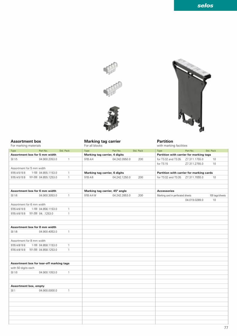
77
selos
S0 1/5 04.900.2053.0 1
9705 A/5/10 B 04.855.1153.0 1
9705 A/5/10 B 04.855.1253.0 1
9705 A/4 04.242.0950.0 200
9705 A/6 04.242.1250.0 200
S0 1/6 04.900.3053.0 1
9705 A/6/10 B 04.856.1153.0 1
9705 A/6/10 B 04. .1253.0 1
S0 1/8 04.900.4053.0 1
9705 A/8/10 B 04.858.1153.0 1
9705 A/8/10 B 04.858.1253.0 1
S0 1/0 04.900.1053.0 1
S0 1 04.900.0000.0 1
1-100
101-200
1-100
101-200
1-100
101-200
9705 A/4 W 04.242.2853.0 200
Z7.311.1755.0 10
Z7.311.2755.0 10
Z7.311.7055.0 10
04.019.0289.0 10
Assortment boxFor marking materials
Marking tag carrierFor all blocks
Partitionwith marking facilities
Type Part No. Std. PackType Part No. Std. Pack Type Part No. Std. Pack
Assortment box for 5 mm width Marking tag carrier, 4 digits
Assortment for 5 mm width
Assortment box for 6 mm width
Assortment for 6 mm width
Assortment box for 8 mm width
Assortment for 8 mm width
Assortment box for tear-off marking tags
with 50 digits each
Assortment box, empty
Marking tag carrier, 6 digits
Marking tag carrier, 45° angle
Partition with carrier for marking tags
for TS 32 and TS 35
for TS 15
Partition with carrier for marking cards
for TS 32 and TS 35
Accessories
Marking card in perforated sheets 100 tags/sheets
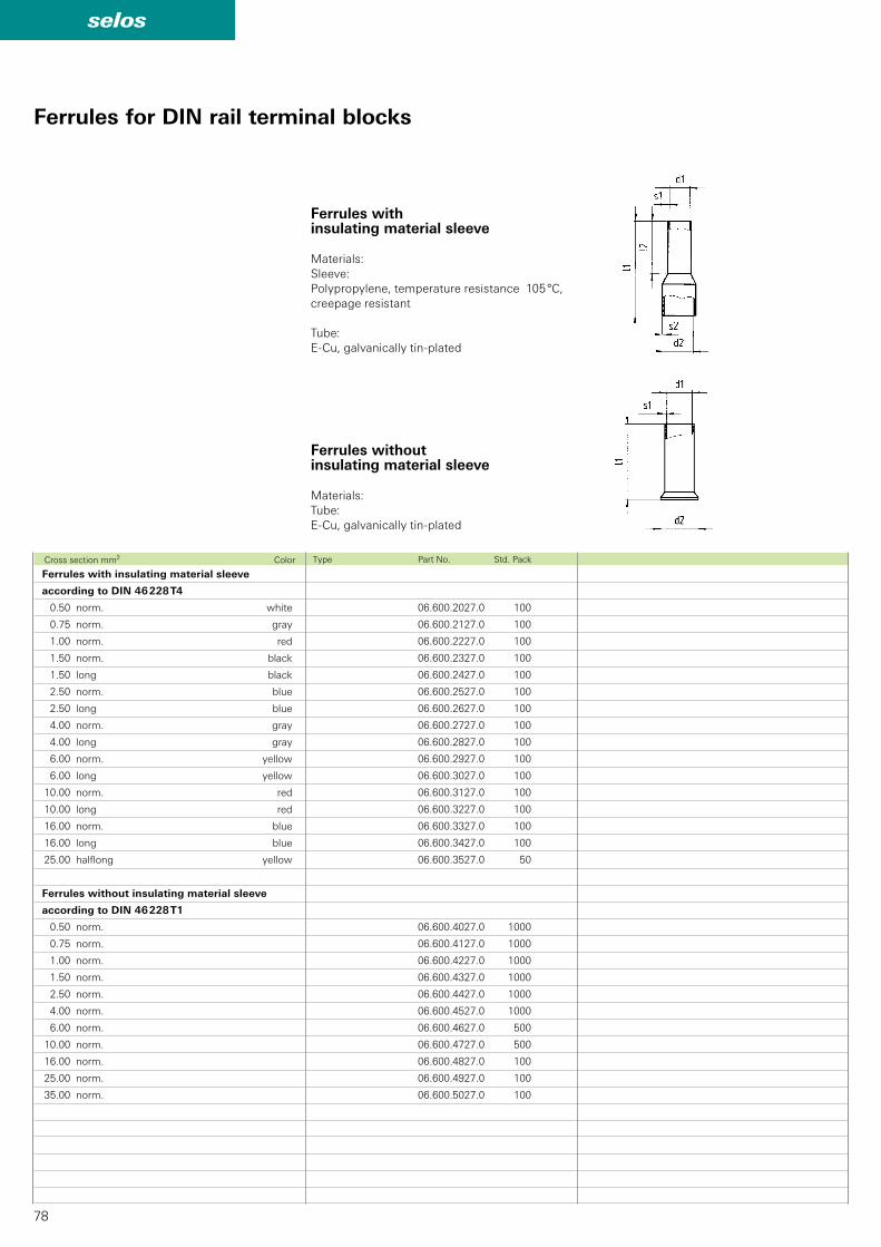
78
selos
06.600.2027.0 100
06.600.2127.0 100
06.600.2227.0 100
06.600.2327.0 100
06.600.2427.0 100
06.600.2527.0 100
06.600.2627.0 100
06.600.2727.0 100
06.600.2827.0 100
06.600.2927.0 100
06.600.3027.0 100
06.600.3127.0 100
06.600.3227.0 100
06.600.3327.0 100
06.600.3427.0 100
06.600.3527.0 50
06.600.4027.0 1000
06.600.4127.0 1000
06.600.4227.0 1000
06.600.4327.0 1000
06.600.4427.0 1000
06.600.4527.0 1000
06.600.4627.0 500
06.600.4727.0 500
06.600.4827.0 100
06.600.4927.0 100
06.600.5027.0 100
Ferrules with insulating material sleeve
Materials:Sleeve:Polypropylene, temperature resistance 105 °C, creepage resistant
Tube: E-Cu, galvanically tin-plated
Ferrules without insulating material sleeve
Materials: Tube: E-Cu, galvanically tin-plated
Type Part No. Std. Pack
Ferrules with insulating material sleeve
according to DIN 46 228 T4
0.50 norm. white
0.75 norm. gray
1.00 norm. red
1.50 norm. black
1.50 long black
2.50 norm. blue
2.50 long blue
4.00 norm. gray
4.00 long gray
6.00 norm. yellow
6.00 long yellow
10.00 norm. red
10.00 long red
16.00 norm. blue
16.00 long blue
25.00 halflong yellow
Ferrules without insulating material sleeve
according to DIN 46 228 T1
0.50 norm.
0.75 norm.
1.00 norm.
1.50 norm.
2.50 norm.
4.00 norm.
6.00 norm.
10.00 norm.
16.00 norm.
25.00 norm.
35.00 norm.
Cross section mm2 Color
Ferrules for DIN rail terminal blocks
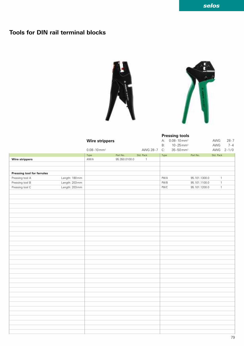
79
selos
AIW/A 95.350.0100.0 1
PW/A 95.101.1300.0 1
PW/B 95.101.1100.0 1
PW/C 95.101.1200.0 1
Type Part No. Std. Pack Type Part No. Std. Pack
Wire strippers
0.08 - 10 mm2 AWG 28 - 7
Pressing toolsA: 0.08 - 10 mm2 AWG 28 - 7
B: 10 - 25 mm2 AWG 7 - 4
C: 35 - 50 mm2 AWG 2 - 1 / 0
Wire strippers
Pressing tool for ferrules
Pressing tool A Length: 180 mm
Pressing tool B Length: 203 mm
Pressing tool C Length: 203 mm
Tools for DIN rail terminal blocks
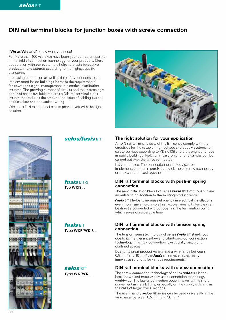
80
selos BIT
selos/fasis BIT
O
DIN rail terminal blocks for junction boxes with screw connection
fasis BIT-STyp WKIS...
fasis BITType WKF / WKIF...
selos BITType WK / WKI...
„We at Wieland” know what you need!
For more than 100 years we have been your competent partner in the field of connection technology for your products. Close cooperation with our customers helps to create innovative products manufactured according to the highest quality standards.
Increasing automation as well as the safety functions to be implemented inside buildings increase the requirements for power and signal management in electrical distribution systems. The growing number of circuits and the increasingly confined space available requires a DIN rail terminal block system that reduces the amount and costs of cabling but still enables clear and convenient wiring.
Wieland’s DIN rail terminal blocks provide you with the right solution.
The right solution for your application
All DIN rail terminal blocks of the BIT series comply with the directives for the setup of high-voltage and supply systems for safety services according to VDE 0108 and are designed for use in public buildings. Isolation measurement, for example, can be carried out with the wires connected.
It‘s your choice. The connection technology can be implemented either in purely spring clamp or screw technology or they can be mixed together.
DIN rail terminal blocks with push-in spring connection
The new installation blocks of series fasis BIT-S with push-in are an outstanding addition to the existing product range.
fasis BIT-S helps to increase efficiency in electrical installations even more, since rigid as well as flexible wires with ferrules can be directly connected without opening the termination point which saves considerable time.
DIN rail terminal blocks with screw connection
The screw connection technology of series selos BIT is the best known and most widely used connection technology worldwide. The lateral connection option makes wiring more convenient in installations, especially on the supply side and in the case of larger cross sections.
The user-friendly selos BIT series can be used universally in the wire range between 0.5 mm2 and 50 mm2.
DIN rail terminal blocks with tension spring connection
The tension spring technology of series fasis BIT stands out due to its maintenance-free and vibration-proof connection technology. The TOP connection is especially suitable for confined spaces.
Due to its great product variety and a wire range between 0.5 mm2 and 16 mm2 the fasis BIT series enables many innovative solutions for various requirements.
selos
81
O
Information about EX e
Technical information
• The information regarding cross sectional area and connection types pertains to unprepared wires without ferrules! Ferrules are not necessary for secure connection. Whenever ferrules are used, make sure that the tools specified by the manufacturer are used exclusively.
• The voltage ratings apply to the terminals in their intended application. When different products are mounted adjacent to each other, the proper isolation distances must be adhered to.
• If the ground blocks of the selos product family are not used in block assemblies, but are mounted to the rail as single terminal blocks, end clamps have to be used.
• A detailed description of technical data, the standards requirements, and the application conditions are available under facts & DATA.
ATEX regulation
• For the use of DIN rail terminal blocks in Ex areas, the regulations of EN 60079-0 apply; whereas for increased safety Ex e the regulations of EN 60079-7 must be followed. For an approximation of the laws of the EU member states, directive 94/9/EG was created, which is generally known as ATEX 100a and which is the basis for harmonization in this field. ATEX stands for ”atmoshpere explosive” while 100a refers to the corresponding article of the EC contract.
• Directive ATEX 100a applies for protection against dust and gas explosions in all industrial Ex areas and in mining.The testing and certificating institutes named in directive ATEX 100a must follow accreditation procedures which are the same throughout Europe.
• In accordance with EN 60070-0/60079-7 and ATEX 100a, these certifying institutes write out EC certificates for prototype tests. These prototype test certificates for components together with the corresponding quality system certification of the supplier are required to obtain the so-called ATEX approval.
• In combination with theO mark, the markings of the Wieland terminal blocks have the following meaning: O Identification II Device group 2 Category G D Areas KEMA Name of testing institute ATEX... Certifcate, year of testing, number
Mounting instructions for Ex e applications
• If feed-through blocks are mounted directly adjacent to other feed-through blocks of a different size, or directly adjacent to ground blocks, the open side of the block group of the same type must be covered by an end plate or partition.
• If adjacent DIN rail terminal blocks are jumpered or if jumpered DIN rail terminal blocks are positioned next to unjumpered DIN rail terminal blocks, a partition plate must be inserted between the individual terminal block groups or at the beginning and end of a laterally or longitudinally connected terminal block (group) in order to meet the specified isolation distances. Notched out and jumpering cross connectors can not be used in Ex areas.
• If the terminal blocks are combined with other certified series and sizes and when their accessories are used, the required creepage distances and clearances must be adhered to.
• The feed through terminal blocks and protective conductor terminal blocks are suitable for enclosures for use in explosive gas atmospheres or for use in the presence of combustible dust. For explosive gas atmospheres these enclosures must satisfy the requirements of EN 60079-0 and EN 60079-7. For combustible dust these enclosures must satisfy the requirements of EN 61241-0 and EN 61241-1 rather EN 50281-1-1.
• The indicated values for the current carrying capability refer to a maximum ambient temperature of 40 °C. When the terminal blocks are loaded with the maximum rated current the temperature rise will be max. 45 K.
• Operating temperature range: -40° C ... +80° C.
DQS certification for all company sectors
• Quality standard as per DIN ISO 9001 in Development, Production and Assembly
• Continued control of the quality standard by means of regular internal and external quality audits
• Compatible with certificates of other countries:– BSI Certificate, Great Britain– SQS Certificate, Switzerland– Aib-Vincotte Certificate, Belgium– ÖQS Certificate, Austria

82
Hotline • advice
Additional information
Technical support
Automation technology:
• Safety technology safety Phone: +49 951 9324-999 e-mail: [email protected]
• Remote power distribution podis® Phone: +49 951 9324-998
• interface: Power supply, industrial Ethernet switches, timer relays, measuring and monitoring relays, coupling relays, analog modules, remote I/O, surge protection, passive interfacesPhone: +49 951 9324-995
• DIN rail terminal blocks fasis, selos Phone: +49 951 9324-991
• Industrial multipole connectors revos Phone: +49 951 9324-992
• PCB terminals and connectors wiecon
Appliance terminals, european terminal strips,housings for electronic components Phone: +49 951 9324-993
Fax: +49 951 9326-991
e-mail: [email protected]
General information and news:
www.wieland-electric.com
Visit our eCAT at
http://eshop.wieland-electric.com
Support
Technical Support
Building services engineering:
• System connectors for building installation gesis CON, gesis RAN, gesis ELECTRONIC Phone: +49 951 9324-996
• DIN rail terminal blocks fasis BIT, selos BIT Phone: +49 951 9324-991
Fax: +49 951 9326-996e-mail: [email protected]
Sales service:
• To contact our sales department regarding availability, delivery schedules, and pricing please callPhone: +49 951 9324-990
Technical Support
Photovoltaics/solar technology:
• Photovoltaics gesis SOLAR Phone: +49 951 9324-972
Fax: +49 951 9326-977e-mail: [email protected]

contacts are green
83Subject to technical modifications!gesis®, podis®, samos® are registered trademarks of Wieland Electric GmbH
Our subsidiaries... and the addresses of our representations worldwide are available at:
www.wieland-electric.com
CANADA
Wieland Electric Inc.
2889 Brighton RoadOakville, Ontario L6H 6C9Phone +1-905-829 8414 Fax +1-905-829 8413 [email protected]
SPAIN
Wieland Electric S.L.
C/ Maria Auxiliadora 2 bajosE-08017 BarcelonaPhone +34-93-252 3820Fax +34-93-252 [email protected]
GREAT BRITAIN
Wieland Electric Ltd.
Riverside Business Centre, Walnut Tree CloseGB-Guildford /Surrey GU1 4UGPhone +44-1483-531 213Fax +44-1483-505 [email protected]
CHINA
Wieland Electric Trading
Unit 2703 International Soho City889 Renmin Rd., Huang Pu DistrictPRC- Shanghai 200010Phone +86-21-63 555 833Fax +86-21-63 550 [email protected]
CZECH REPUBLIC
(Production)Wieland Electric s.r.o.
Nadražni 1557356 01 SokolovPhone +420-352 302 011Fax +420-352 302 027
ITALY
Wieland Electric S.r.l.
Via Edison, 209I-20019 Settimo MilanesePhone +39-02-48 91 63 57Fax +39-02-48 92 06 [email protected]
USA
Wieland Electric Inc.
49 International RoadBurgaw, N.C. 28425Phone +1-910-259 5050Fax +1-910-259 [email protected]
FRANCE
Wieland Electric SARL.
Le Céramê Hall 647, avenue des GenottesCS 4831395803 Cergy-Pontoise CedexPhone +33-1-30 32 07 07Fax +33-1-30 32 07 [email protected]
DENMARK
Wieland Electric A/S
Vallørækken 26DK-4600 KøgePhone +45-70-26 66 35Fax +45-70-26 66 [email protected]
F Informational material for
ordering and for downloading
from our websites
POLAND
Wieland Electric Sp. Zo.o.
Św. Antoniego 8
62-080 Swadzim
Phone +48-61-2 22 54 00
Fax +48-61-8 40 71 66

selos
selos
selos
DIN Rail Terminal Blockswith Screw Connection
Professional Screw Technology
Headquarters:
Wieland Electric GmbH
Brennerstraße 10 - 14
96052 Bamberg, Germany
Sales and Marketing Center:
Wieland Electric GmbH
Benzstraße 9
96052 Bamberg, Germany
Phone +49 (0951) 9324-0
Fax +49 (0951) 9324-198
www.wieland-electric.com
www.gesis.com
Industrial technology Solutions for the control cabinet • DIN rail terminal blocks – Screw, tension spring or push-in connection technology – Wire cross sections up to 240 mm2
– Numerous special functions – Software solutions interfacing to CAE systems • Safety – Safe signal acquisition – Safety switching devices – Modular safety modules – Compact safety controllers – Applicative consultancy and training • Network engineering and fi eldbus systems – Remote maintenance via VPN industrial router and VPN service portal – Industrial Ethernet switches – PLC and I/O systems, standard and increased
environmental conditions • Interface – Power supply units – Overvoltage protection – Coupling relays, semiconductor switches – Timer relays, measuring and monitoring relays – Analog coupling and converter modules – Passive interfaces
Solutions for fi eld applications • Decentralized installation and automation technology – Electrical installation for wind tower – Fieldbus interfaces and motor starters • Connectors for industrial applications – Rectangular and round connectors – Aluminum or plastic housings – Degree of protection up to IP 68 – Current-carrying capacity up to 100 A – Connectors for hazardous areas – Modular, application-specifi c technology
PC board terminals and connectors – Screw or spring clamp connection technology – Spacings: 3.5 mm to 10.16 mm – Refl ow or wave soldering process
Building and installation technology • Building installation systems – Main power supply connectors IP 20/IP 65 ... IP 68 – Bus connectors – Low-voltage connectors – Power distribution system with fl at cables – Distribution systems – Bus systems in KNX, LON and radio technology – DIN rail terminal blocks for electrical installations – Overvoltage protection
0125.0 B 04/12