prof. samit raychaudhari , dept ofce (co pi) dr. kk … -5.pdf · eucenter report, 2016 precast...
TRANSCRIPT

Development of draft protocol for testing of structural components and systems for use in schemes under ‘Housing for all’ project of the Government of India
Prof. Sudhir Misra, Dept of CE (PI)Prof. Samit Raychaudhari , Dept of CE (Co‐PI)
Dr. KK Bajpai, Dept of CE (Co‐PI)
1MHUPA- Protocol for testing, HFA23/11/2016
Department of Institute of Technology Kanpur, KANPUR

Systemleveltestingmeansthatthetestingisdoneforthecompleteassemblyortheproductlikecustomeratthetoplevellookingfortheharmonyamongdifferentcomponents
Componentleveltesting(orUnittesting)isfocussedonthefunctionalityofaparticularpartwithoutconsideringmuchonhowitworkswithothers.
Systemvs.ComponentLevelTesting
System MasonryStructure RCStructure SteelStructure TimberStructure PrecastconcreteStructure
Component Slab WallPanel beam Column Beam‐columnconnection

ForSystems&Components:Teststandardsforperformanceofdifferentconstructionpracticese.g.masonrywalls,Precastslabsandbeams,RCBeam‐columnsetc.
• Subjectedtoin‐planeandout‐of‐planebending• Cyclicloading• WindLoading
Typesofcomponentinclude‐Cast‐in‐situcomponentPrecastorPrefabricatedcomponent
Protocolsfortestingofstructuralcomponentsandsystems

Cast‐in‐Situ Precast
Cast‐in‐situvs.Precast• precastconcretestructuresareabletoresisttoearthquakeloadingasreliablyasanalogouscast‐inplaceones.
• Energydissipationinprefabricatedcolumnsoccurswithinavolumeofmaterialwhichisequaltothattopandbottomedgesectionsofcast‐in‐placecolumnsdesignedtowithstandthesamebaseshearforce.
Ferraraetal.2004

Precast concrete structures are traditionally designed as moment resistingframes with plastic hinges occurring at the column base, and beams hingedto the columns.
Replacement with Precast system gives the advantage of designingcontinuous beams with a reduced beam depth, or with an increase of eitherspan length or carried load.
Precastbeam‐columnconnection

ExperimentalSetUpforJointTesting
CyclicLoadingProtocol InstrumentationSet‐UpEUCENTERReport,2016
Precastbeam‐columnconnection

Inputmotion,scaledtoPGAof1g.
ModifiedResponseSpectrabyEC8soilFactorB
(Negro et al. 2013)
Precastbeam‐columnconnection
PseudodynamicTesting

A.Shearwallsandhingedbeam–columnjoints
B.Hingedbeam–columnjoints
• Thepresenceoftwostiffprecastwallunitsinprototype1wasquiteeffectiveinlimitingthemaximuminter‐storeydriftratiosforboththeserviceabilityandultimatelimitstates.
(T=0.3Sec)
Theseismicresponseofprototype2washighlyinfluencedbytheeffectsofhighermodes. Thisresultsintolargeforcedemandsin
theconnectionsinthenonlinearregime. The1%driftlimitationwasexceeded,
precastsystemwithhingedbeam‐tocolumnjointswascharacterizedbyexcessivedeformability.
Nosignificantdamageinitsstructuralmembers.(T=1.09Sec)
(Negro et al. 2013)
Precastbeam‐columnconnection

C.Hingedbeam–columnatthe1stand2ndfloorandemulativeatthe3rd
D.Emulativebeam–columnjoints
After the seismic test results of prototype 3,the concept of emulative beam–column jointsat the top floor only was not much effective.• The effect of higher modes is also
significant.(T=1.08 Sec)
Finally, when activated at all the floors, theproposed connection system is quite effectiveas a means of implementing dry precast(quasi) emulative moment‐resisting frames. Dense flexural cracking at the base of the
ground floor columns, but again withoutconsiderable damage.(T=0.66 Sec)
(Negro et al. 2013)
Precastbeam‐columnconnection

Category1:connectionsisthatbetweenadjacentfloororroofelements.Category2:connectionsbetweenfloororroofpanelsandsupportingbeams.Category3:connectionsbetweencolumnsandbeams.Category4:connectionsusedtojoincolumnsandfoundationsCategory5:connectionsbetweenwall(orcladdingpanels)andslabelements.
(Bournas et al. 2013)
Precastbeam‐columnconnection
Behaviorofconnection

(Bournas et al. 2013)
(a) Seatingofasecondarybeamonthecolumncapital.
(b) Acentralbeam–columnjoint.(c) Detailofapinnedbeam–columnjoint
connection.(d) Specialdowelswithincreased
diameteratthecriticalsection.
PinnedJointConnection:• It is able to transfer shear and axial
forces both for the gravity and seismicforces and possible uplifting forces dueto overturning.
• Bydefinition,theycannottransfermomentandtorsion,althoughinrealitytheydotransferasmallamountofbendingmoment.
• Thehorizontalconnectionbetweenthebeamandthecolumnwasestablishedbymeansoftwoverticalsteeldowelswhichwereprotrudingfromthecolumnintospecialbeamsleeves.
Precastbeam‐columnconnection

(Bournas et al. 2013)
(a) Connectorusedtorealizedryemulativebeam–columnjoints.
(b) Testset‐upadoptedtoassessthetensilecapacityoftheconnectionsystem.
• The second beam–column connectiontype, which emulates fixed beam–columnjoints.
• In order to provide continuity to thelongitudinal reinforcement crossing thejoint, an innovative ductile connectionsystem, embedded in the precastelements, was activated.
• This connection system comprises foursteel rebars slightly enlarged at theirends, two thick steel plates and a bolt thatconnects the two steel plates
(c)Typicalloadversusdisplacementcurveofthebareconnectionsystem.(d)Ductileruptureofthelongitudinalrebars.
Precastbeam‐columnconnection
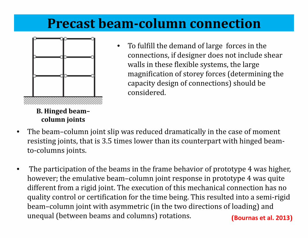
B.Hingedbeam–columnjoints
• Tofulfillthedemandoflargeforcesintheconnections,ifdesignerdoesnotincludeshearwallsintheseflexiblesystems,thelargemagnificationofstorey forces(determiningthecapacitydesignofconnections)shouldbeconsidered.
• Thebeam–columnjointslipwasreduceddramaticallyinthecaseofmomentresistingjoints,thatis3.5timeslowerthanitscounterpartwithhingedbeam‐to‐columnsjoints.
• Theparticipationofthebeamsintheframebehaviorofprototype4washigher,however;theemulativebeam–columnjointresponseinprototype4wasquitedifferentfromarigidjoint.Theexecutionofthismechanicalconnectionhasnoqualitycontrolorcertificationforthetimebeing.Thisresultedintoasemi‐rigidbeam–columnjointwithasymmetric(inthetwodirectionsofloading)andunequal(betweenbeamsandcolumns)rotations. (Bournas et al. 2013)
Precastbeam‐columnconnection
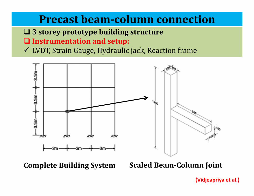
3storey prototypebuildingstructure Instrumentationandsetup: LVDT,StrainGauge,Hydraulicjack,Reactionframe
CompleteBuildingSystem ScaledBeam‐ColumnJoint
Precastbeam‐columnconnection
(Vidjeapriya et al.)

Experimentalsetupandmodels 3experimentalmodels• Monolithic(cast‐in‐situ)(ML)• Precastmemberswithsinglestiffener(PC‐SS)• Precastmemberswithdoublestiffener(PC‐DS)
Reversecyclicdisplacementcontrolled
loading
Precastbeam‐columnconnection
(Vidjeapriya et al.)

SampleResultsPrecastbeam‐columnconnection
(Vidjeapriya et al.)

PerformanceEvaluation(Cast‐in‐situvs.Precast)• Columndamageisminimalinprecastsystems• Doublestiffenerprecastsystememulatesperformanceofcastinsitumonolithicsectionconsideringstrengthanddamping
• PC‐DShasbetterductilitythanthatofSpecimenPC‐SSandMLspecimen
CracksinPCjointCracksinMLjoint
Precastbeam‐columnconnection
(Vidjeapriya et al.)

PrecastDiaphragmwallpanelAprecastwallpanelsystemcanbecomprisedof:
Flatorcurvedpanels(solid,hollow‐core,orinsulated) Windowormullionpanels Ribbedpanels Double‐tee

Excessivegapopeningbetweenpanels
Shearslip
Undesirabledeformationsalonghorizontaljoints
WallandHorizontalLoading
TypicalWallDeformation:• DuetoShear• DuetoFlexure
EUCENTERReport,2016
PrecastDiaphragmwallpanelHorizontalloaddeformationScenarios:

CantileverWallCoupledWall
RockingWall
• Cantileverwallsresisttheoverturningmomentresultingfromthelateralforcesbybending.
• Coupledwallsresisttheoverturningmomentnotonlybybendingoftheindividualwallsbutalsothroughanaxialforcecouple.
• Rockingwallsresistoverturningmomentatthebaseofthewallsthroughthecouplearisingfromtheeccentricitybetweentheactinggravityloadandthereactionatthewall‐foundationinterface.
EUCENTERReport,2016
PrecastDiaphragmwallpanel
Horizontalloadcarryingmechanism

• 3storey Precastboxstructure.• SymmetricStructuretoavoidthetwist.• Instrumentation:LVDT,StrainGauge,Potentiometer,Accelerometer.
• ShakeTableMovement:WhiteNoiseofdifferentintensity.
Leeetal.1996
PrecastDiaphragmwallpanel

Results:• ModelwastakeninNon‐linearrangeduringthe0.8gwithrocking
motion.• CracksappearedinHorizontaljointsin0.12gandwerepropagatedinthe
horizontaldirection.• In1.4g,thejointboxwascrushedinHorizontaljointswithoutanycrack
inwallpanelsandverticaljoints.
Leeetal.1996
PrecastDiaphragmwallpanel

PrecastDiaphragmwallpanel
In‐planeloadingsetups
Instrumentation HydraulicJack LVDT Straingauges Loadcell Shearactuator

Thetestthusprovidesanestimateofaverage connectoryield,peakstrength,andthedeformationcapacity.
Monotonicshearprotocolconsistsofthreecyclesto0.01inch
Out‐of‐planemonotonicsheartests
Instrumentation HydraulicJack LVDT Straingauges Loadcell
PrecastDiaphragmwallpanel

Forcecontrolled MonotonicIn‐planeShear CyclicIn‐planeShear MonotonicIn‐planeTension CyclicIn‐planeTensionandCompression
MonotonicIn‐planeShearwithProportionalTension
DisplacementcontrolledMonotonicandCyclicShearDeformationwithaTargetAxialLoadof0kips;
CyclicShearDeformationwithaTargetAxialLoadof10kips
Inplaneloadingprotocols
Forcecontrolled
Displacementcontrolled
PrecastDiaphragmwallpanel
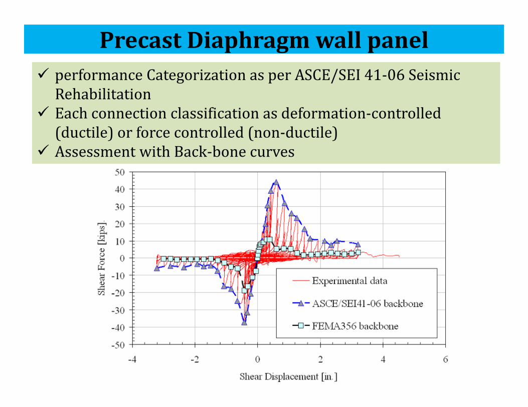
performanceCategorizationasperASCE/SEI41‐06SeismicRehabilitation
Eachconnectionclassificationasdeformation‐controlled(ductile)orforcecontrolled(non‐ductile)
AssessmentwithBack‐bonecurves
PrecastDiaphragmwallpanel

Thepurposeofthetest‐Thesystemcanhandleaboveandbeyondthetypicaldesignloadsweworkwith,whileofferingadvantagesoverothersystems– advantagessuchaslighterweightandinsulation
PrecastBeams
Precast.org

loadtestingofnewprecastconcretefloorplanksystem
DeadloadtestonPre‐stressedPrecastBeams‐fordifferentmagnitudeofstaticloads
Precast.org
PrecastBeams

deflectionatmid‐spanofplank Crackingatmid‐span
StaticDeflectionsweremeasuredanddeadloadonthecomponentissimulated.• Deflectionismeasuredimmediatelyafterloading.• Deflectionismeasured136hoursafterloading.• Crackpropagationismonitoredfordifferentdeadloads
Precast.org
PrecastBeams
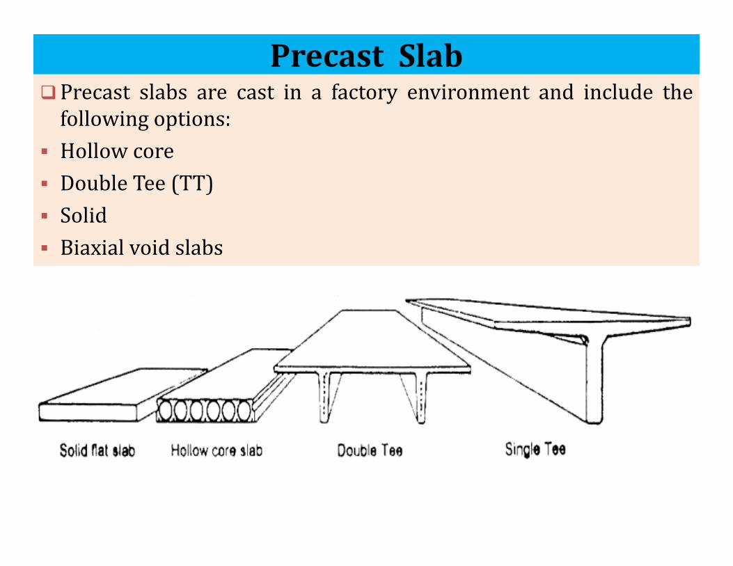
PrecastSlabPrecast slabs are cast in a factory environment and include thefollowing options:
Hollow core Double Tee (TT) Solid Biaxial void slabs

PrecastSlabDepending on the position of slab following slab panels areconsidered for testing
Externaldiaphragm
Intermediatediaphragmsupport
Diaphragmpaneltopanelinteraction
Externaldiaphragm
Internaldiaphragmconnection
(Fleischman et al.)

PrecastSlabLoadingprotocols
Instrumentation Shearactuator LVDT Straingauges
(Fleischman et al.)

ReinforcedConcreteBeam‐ColumnJoint Since their constituent materials have limited strengths, the jointshave limited force carrying capacity.
Repairing damaged joints is difficult, and so damage must beavoided.
Thus, beam‐column joints must be designed to resist earthquakeeffects.
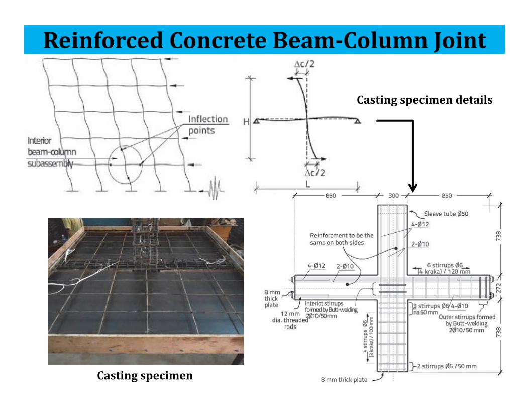
Castingspecimen
Castingspecimendetails
ReinforcedConcreteBeam‐ColumnJoint

The displacement at the ends of the beams wasincreased by steps from 0.25 % up to a drift of 1.0 %per drift amplitude, then two cycles for each driftamplitude greater than 1 %
A total of twelve displacement cycles were applied upto 5 % drift cycle
Instrumentation HydraulicJack LVDT LaserSensor Straingauges Loadcell
ReinforcedConcreteBeam‐ColumnJoint
Loadingprotocols

ReinforcedConcreteBeam‐ColumnJoint PerformanceofspecimenCrackpropagation
RecordedStrain

SteelBeam‐ColumnJoint Steel beam‐column joints are vulnerable to brittle fracture duringseismic events
There are higher chances of formation of plastic hinges near thebeam‐column joint during nonlinear response of structure
Thus, beam‐column joints must be designed to resist earthquakeeffects.

SteelBeam‐ColumnJointPossibleTestSetups

SampleTestSetup
Instrumentation HydraulicJack LVDT Straingauges Loadcell
SteelBeam‐ColumnJoint

SteelBeam‐ColumnJointLoadingProtocol InitialStage
DeformedStage

Realisticearthquaketypeloadingforprototypicalstructuralsystems
IITKPseudoDynamicsTestingFacility

IITKPseudoDynamicsTestingFacility• Equationsof
motionsaresolvedon‐linefordisplacementstobeappliedinrealtimewhileupdatingthesystemparametersfromon‐linemeasurementsofforcesanddisplacements.
• Effectofinertiaforceisaccountedforinapproximatesenseandstrainrateeffectsarenotconsideredastestiscarriedoutatslowrate.PseudoDynamic(PsD)Test

IITKPseudoDynamicsTestingFacility
• Synthesisofnumericalmodeling andexperimentaltesting.
• Requireadequatesimulationofboundaryconditionsattheinterface
HybridPsD usingSubstructures

Characteristics:TableSize 1.2mx1.8mWeightofTable 8kNMaximumPayload 40kNMaximumDisplacement 75mmMaximumVelocity 1.5m/sMaximumAcceleration 5gFrequencyRange upto 50Hz
IITKShakeTableTestingFacility
• Forsmallscaledynamicmodeltestingi.e.componenttesting

ISMB600sectionsforallmembersHeight:4.2m,Lateralload:4000kN andOverturningmomentcapacity:6000kNm
IITKCyclicTestingFacility
ReactionFrame
ForWallTestingor
FrameTesting(SmallScale)

IITKWindTunnelFacility
TallChimney TallBuilding
CivilEngineeringApplicationofWindTunnel

References• Naito, Clay, and Ruirui Ren. "Evaluation Methodology for Precast Concrete Diaphragm
Connectors Based on Structural Testing." (2008).• Fleischman, Robert B., et al. "Development of a seismic design methodology for
precast diaphragms." (2004).• Ahmed, Saddam M., and Umarani Gunasekaran. "Testing and evaluation of reinforced
concrete beam‐column‐slab joint." Građevinar 66.01. (2014): 21‐36.• Lee, Cheol‐Ho, et al. "Cyclic seismic testing of steel moment connections reinforced
with welded straight haunch." Engineering Structures 25.14 (2003): 1743‐1753.• “SAC ‐ Nonlinear Structural Dynamics And Control Research” by SACJ Venture• Lee, HL., et al. “Shake Table Test of Precast Concrete Wall Structure”. 11th World
conference on Earthquake Engineering, Elsevier Science, 1996.• Ferrara, L., et al. "Precast vs. cast‐in‐situ reinforced concrete industrial buildings
under earthquake loading: an assessment via pseudo‐dynamic tests." Proceedings ofthe 13thWCEE. 2004.
• Northeast Precast company blogs‐ By Peter Gorgas (Precast.org)• “Numerical and experimental evaluation of the seismic response of precast wall
connections”, EUCENTER Report, 2016• Negro, Paolo, Dionysios A. Bournas, and Francisco J. Molina. "Pseudodynamic tests on
a full‐scale 3‐storey precast concrete building: global response." EngineeringStructures 57 (2013): 594‐608.
• Bournas, Dionysios A., Paolo Negro, and Francisco J. Molina. "Pseudodynamic tests ona full‐scale 3‐storey precast concrete building: behavior of the mechanicalconnections and floor diaphragms." Engineering Structures 57 (2013): 609‐627.

ThankYou