prof. dr.-ing. jochen schiller, ss057.1 mobile communications chapter 7: wireless lans ...
TRANSCRIPT
Prof. Dr.-Ing. Jochen Schiller, http://www.jochenschiller.de/ MC SS05 7.1
Mobile Communications Chapter 7: Wireless LANs
Characteristics IEEE 802.11
PHY MAC Roaming .11a, b, g, h, i …
HIPERLAN Bluetooth / IEEE 802.15.x IEEE 802.16/.20/.21/.22 RFID Comparison

Prof. Dr.-Ing. Jochen Schiller, http://www.jochenschiller.de/ MC SS05 7.2
Mobile Communication Technology according to IEEE
Local wireless networksWLAN 802.11
802.11a
802.11b802.11i/e/…/w
802.11g
WiFi802.11h
Personal wireless nwWPAN 802.15
802.15.4
802.15.1 802.15.2
Bluetooth
802.15.4a/bZigBee
802.15.3
Wireless distribution networksWMAN 802.16 (Broadband Wireless Access)
802.20 (Mobile Broadband Wireless Access)
+ Mobility
WiMAX
802.15.3a/b
802.15.5

Prof. Dr.-Ing. Jochen Schiller, http://www.jochenschiller.de/ MC SS05 7.3
Characteristics of wireless LANs
Advantages very flexible within the reception area Ad-hoc networks without previous planning possible (almost) no wiring difficulties (e.g. historic buildings, firewalls) more robust against disasters like, e.g., earthquakes, fire - or users pulling
a plug...
Disadvantages typically very low bandwidth compared to wired networks
(1-10 Mbit/s) due to shared medium many proprietary solutions, especially for higher bit-rates, standards take
their time (e.g. IEEE 802.11) products have to follow many national restrictions if working wireless, it
takes a vary long time to establish global solutions like, e.g., IMT-2000

Prof. Dr.-Ing. Jochen Schiller, http://www.jochenschiller.de/ MC SS05 7.4
Design goals for wireless LANs
global, seamless operation low power for battery use no special permissions or licenses needed to use the LAN robust transmission technology simplified spontaneous cooperation at meetings easy to use for everyone, simple management protection of investment in wired networks security (no one should be able to read my data), privacy (no one should
be able to collect user profiles), safety (low radiation) transparency concerning applications and higher layer protocols, but also
location awareness if necessary

Prof. Dr.-Ing. Jochen Schiller, http://www.jochenschiller.de/ MC SS05 7.5
Comparison: infrared vs. radio transmission
Infrared uses IR diodes, diffuse light,
multiple reflections (walls, furniture etc.)
Advantages simple, cheap, available in
many mobile devices no licenses needed simple shielding possible
Disadvantages interference by sunlight, heat
sources etc. many things shield or absorb IR
light low bandwidth
Example IrDA (Infrared Data Association)
interface available everywhere
Radio typically using the license free
ISM band at 2.4 GHz
Advantages experience from wireless WAN
and mobile phones can be used coverage of larger areas
possible (radio can penetrate walls, furniture etc.)
Disadvantages very limited license free
frequency bands shielding more difficult,
interference with other electrical devices
Example Many different products
Prof. Dr.-Ing. Jochen Schiller, http://www.jochenschiller.de/ MC SS05 7.6
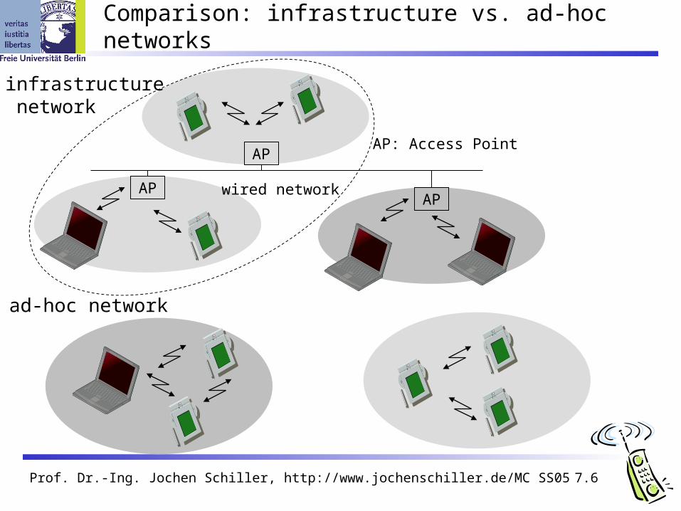
Comparison: infrastructure vs. ad-hoc networks
infrastructure network
ad-hoc network
APAP
AP
wired network
AP: Access Point

Prof. Dr.-Ing. Jochen Schiller, http://www.jochenschiller.de/ MC SS05 7.7
802.11 - Architecture of an infrastructure network
Station (STA) terminal with access mechanisms
to the wireless medium and radio contact to the access point
Basic Service Set (BSS) group of stations using the same
radio frequency
Access Point station integrated into the wireless
LAN and the distribution system
Portal bridge to other (wired) networks
Distribution System interconnection network to form
one logical network (EES: Extended Service Set) based on several BSS
Distribution System
Portal
802.x LAN
Access Point
802.11 LAN
BSS2
802.11 LAN
BSS1
Access Point
STA1
STA2 STA3
ESS

Prof. Dr.-Ing. Jochen Schiller, http://www.jochenschiller.de/ MC SS05 7.8
802.11 - Architecture of an ad-hoc network
Direct communication within a limited range
Station (STA):terminal with access mechanisms to the wireless medium
Independent Basic Service Set (IBSS):group of stations using the same radio frequency
802.11 LAN
IBSS2
802.11 LAN
IBSS1
STA1
STA4
STA5
STA2
STA3

Prof. Dr.-Ing. Jochen Schiller, http://www.jochenschiller.de/ MC SS05 7.9
IEEE standard 802.11
mobile terminal
access point
fixedterminal
application
TCP
802.11 PHY
802.11 MAC
IP
802.3 MAC
802.3 PHY
application
TCP
802.3 PHY
802.3 MAC
IP
802.11 MAC
802.11 PHY
LLC
infrastructurenetwork
LLC LLC
Prof. Dr.-Ing. Jochen Schiller, http://www.jochenschiller.de/ MC SS05 7.10
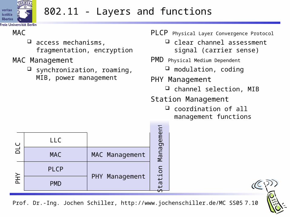
802.11 - Layers and functions
PLCP Physical Layer Convergence Protocol
clear channel assessment signal (carrier sense)
PMD Physical Medium Dependent
modulation, coding
PHY Management channel selection, MIB
Station Management coordination of all management
functions
PMD
PLCP
MAC
LLC
MAC Management
PHY Management
MAC access mechanisms, fragmentation,
encryption
MAC Management synchronization, roaming, MIB,
power management
PH
YD
LC
Sta
tion
Man
agem
ent

Prof. Dr.-Ing. Jochen Schiller, http://www.jochenschiller.de/ MC SS05 7.11
802.11 - Physical layer (classical)
3 versions: 2 radio (typ. 2.4 GHz), 1 IR data rates 1 or 2 Mbit/s
FHSS (Frequency Hopping Spread Spectrum) spreading, despreading, signal strength, typ. 1 Mbit/s min. 2.5 frequency hops/s (USA), two-level GFSK modulation
DSSS (Direct Sequence Spread Spectrum) DBPSK modulation for 1 Mbit/s (Differential Binary Phase Shift Keying),
DQPSK for 2 Mbit/s (Differential Quadrature PSK) preamble and header of a frame is always transmitted with 1 Mbit/s, rest
of transmission 1 or 2 Mbit/s chipping sequence: +1, -1, +1, +1, -1, +1, +1, +1, -1, -1, -1 (Barker code) max. radiated power 1 W (USA), 100 mW (EU), min. 1mW
Infrared 850-950 nm, diffuse light, typ. 10 m range carrier detection, energy detection, synchronization
Prof. Dr.-Ing. Jochen Schiller, http://www.jochenschiller.de/ MC SS05 7.12
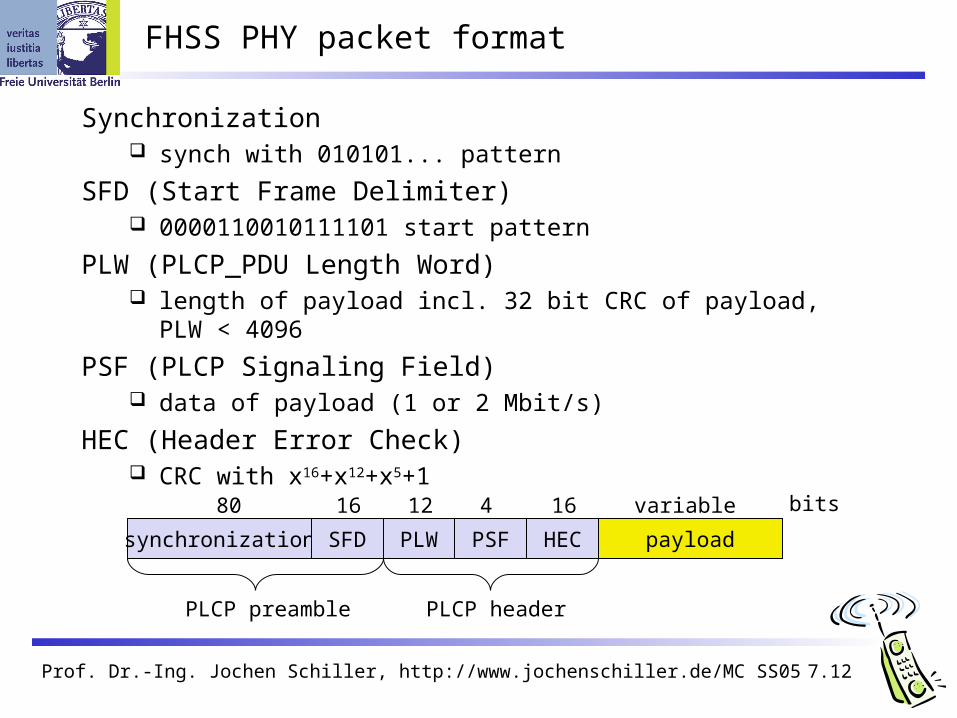
FHSS PHY packet format
synchronization SFD PLW PSF HEC payload
PLCP preamble PLCP header
80 16 12 4 16 variable bits
Synchronization synch with 010101... pattern
SFD (Start Frame Delimiter) 0000110010111101 start pattern
PLW (PLCP_PDU Length Word) length of payload incl. 32 bit CRC of payload, PLW < 4096
PSF (PLCP Signaling Field) data of payload (1 or 2 Mbit/s)
HEC (Header Error Check) CRC with x16+x12+x5+1

Prof. Dr.-Ing. Jochen Schiller, http://www.jochenschiller.de/ MC SS05 7.13
DSSS PHY packet format
synchronization SFD signal service HEC payload
PLCP preamble PLCP header
128 16 8 8 16 variable bits
length
16
Synchronization synch., gain setting, energy detection, frequency offset compensation
SFD (Start Frame Delimiter) 1111001110100000
Signal data rate of the payload (0A: 1 Mbit/s DBPSK; 14: 2 Mbit/s DQPSK)
Service Length future use, 00: 802.11 compliant length of the payload
HEC (Header Error Check) protection of signal, service and length, x16+x12+x5+1
Prof. Dr.-Ing. Jochen Schiller, http://www.jochenschiller.de/ MC SS05 7.14
802.11 - MAC layer I - DFWMAC
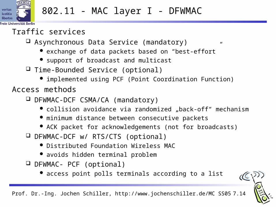
Traffic services Asynchronous Data Service (mandatory)
exchange of data packets based on “best-effort” support of broadcast and multicast
Time-Bounded Service (optional) implemented using PCF (Point Coordination Function)
Access methods DFWMAC-DCF CSMA/CA (mandatory)
collision avoidance via randomized „back-off“ mechanism minimum distance between consecutive packets ACK packet for acknowledgements (not for broadcasts)
DFWMAC-DCF w/ RTS/CTS (optional) Distributed Foundation Wireless MAC avoids hidden terminal problem
DFWMAC- PCF (optional) access point polls terminals according to a list
Prof. Dr.-Ing. Jochen Schiller, http://www.jochenschiller.de/ MC SS05 7.15
802.11 - MAC layer II
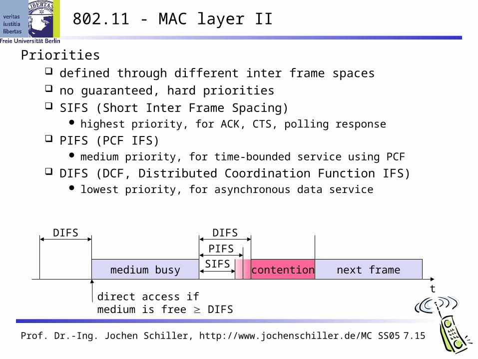
Priorities defined through different inter frame spaces no guaranteed, hard priorities SIFS (Short Inter Frame Spacing)
highest priority, for ACK, CTS, polling response PIFS (PCF IFS)
medium priority, for time-bounded service using PCF DIFS (DCF, Distributed Coordination Function IFS)
lowest priority, for asynchronous data service
t
medium busySIFS
PIFS
DIFSDIFS
next framecontention
direct access if medium is free DIFS

Prof. Dr.-Ing. Jochen Schiller, http://www.jochenschiller.de/ MC SS05 7.16
t
medium busy
DIFSDIFS
next frame
contention window(randomized back-offmechanism)
802.11 - CSMA/CA access method I
station ready to send starts sensing the medium (Carrier Sense based on CCA, Clear Channel Assessment)
if the medium is free for the duration of an Inter-Frame Space (IFS), the station can start sending (IFS depends on service type)
if the medium is busy, the station has to wait for a free IFS, then the station must additionally wait a random back-off time (collision avoidance, multiple of slot-time)
if another station occupies the medium during the back-off time of the station, the back-off timer stops (fairness)
slot timedirect access if medium is free DIFS

Prof. Dr.-Ing. Jochen Schiller, http://www.jochenschiller.de/ MC SS05 7.17
802.11 - competing stations - simple version
t
busy
boe
station1
station2
station3
station4
station5
packet arrival at MAC
DIFSboe
boe
boe
busy
elapsed backoff time
bor residual backoff time
busy medium not idle (frame, ack etc.)
bor
bor
DIFS
boe
boe
boe bor
DIFS
busy
busy
DIFSboe busy
boe
boe
bor
bor

Prof. Dr.-Ing. Jochen Schiller, http://www.jochenschiller.de/ MC SS05 7.18
802.11 - CSMA/CA access method II
Sending unicast packets station has to wait for DIFS before sending data receivers acknowledge at once (after waiting for SIFS) if the packet was
received correctly (CRC) automatic retransmission of data packets in case of transmission errors
t
SIFS
DIFS
data
ACK
waiting time
otherstations
receiver
senderdata
DIFS
contention

Prof. Dr.-Ing. Jochen Schiller, http://www.jochenschiller.de/ MC SS05 7.19
802.11 - DFWMAC
Sending unicast packets station can send RTS with reservation parameter after waiting for DIFS
(reservation determines amount of time the data packet needs the medium) acknowledgement via CTS after SIFS by receiver (if ready to receive) sender can now send data at once, acknowledgement via ACK other stations store medium reservations distributed via RTS and CTS
t
SIFS
DIFS
data
ACK
defer access
otherstations
receiver
senderdata
DIFS
contention
RTS
CTSSIFS SIFS
NAV (RTS)NAV (CTS)

Prof. Dr.-Ing. Jochen Schiller, http://www.jochenschiller.de/ MC SS05 7.20
Fragmentation
t
SIFS
DIFS
data
ACK1
otherstations
receiver
senderfrag1
DIFS
contention
RTS
CTSSIFS SIFS
NAV (RTS)NAV (CTS)
NAV (frag1)NAV (ACK1)
SIFSACK2
frag2
SIFS

Prof. Dr.-Ing. Jochen Schiller, http://www.jochenschiller.de/ MC SS05 7.21
DFWMAC-PCF I
PIFS
stations‘NAV
wirelessstations
point coordinator
D1
U1
SIFS
NAV
SIFSD2
U2
SIFS
SIFS
SuperFramet0
medium busy
t1

Prof. Dr.-Ing. Jochen Schiller, http://www.jochenschiller.de/ MC SS05 7.22
DFWMAC-PCF II
tstations‘NAV
wirelessstations
point coordinator
D3
NAV
PIFSD4
U4
SIFS
SIFSCFend
contentionperiod
contention free period
t2 t3 t4
Prof. Dr.-Ing. Jochen Schiller, http://www.jochenschiller.de/ MC SS05 7.23
802.11 - Frame format
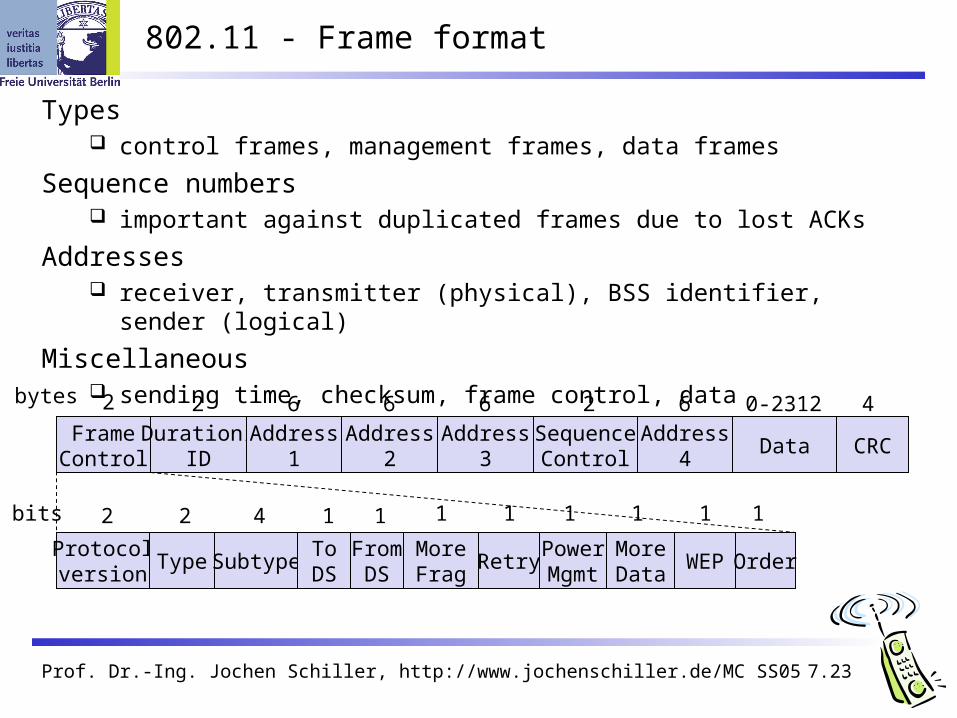
Types control frames, management frames, data frames
Sequence numbers important against duplicated frames due to lost ACKs
Addresses receiver, transmitter (physical), BSS identifier, sender (logical)
Miscellaneous sending time, checksum, frame control, data
FrameControl
Duration/ID
Address1
Address2
Address3
SequenceControl
Address4
Data CRC
2 2 6 6 6 62 40-2312bytes
Protocolversion
Type SubtypeToDS
MoreFrag
RetryPowerMgmt
MoreData
WEP
2 2 4 1
FromDS
1
Order
bits 1 1 1 1 1 1

Prof. Dr.-Ing. Jochen Schiller, http://www.jochenschiller.de/ MC SS05 7.24
MAC address format
scenario to DS fromDS
address 1 address 2 address 3 address 4
ad-hoc network 0 0 DA SA BSSID -infrastructurenetwork, from AP
0 1 DA BSSID SA -
infrastructurenetwork, to AP
1 0 BSSID SA DA -
infrastructurenetwork, within DS
1 1 RA TA DA SA
DS: Distribution SystemAP: Access PointDA: Destination AddressSA: Source AddressBSSID: Basic Service Set IdentifierRA: Receiver AddressTA: Transmitter Address

Prof. Dr.-Ing. Jochen Schiller, http://www.jochenschiller.de/ MC SS05 7.25
Special Frames: ACK, RTS, CTS
Acknowledgement
Request To Send
Clear To Send
FrameControl
DurationReceiverAddress
TransmitterAddress
CRC
2 2 6 6 4bytes
FrameControl
DurationReceiverAddress
CRC
2 2 6 4bytes
FrameControl
DurationReceiverAddress
CRC
2 2 6 4bytes
ACK
RTS
CTS

Prof. Dr.-Ing. Jochen Schiller, http://www.jochenschiller.de/ MC SS05 7.26
802.11 - MAC management
Synchronization try to find a LAN, try to stay within a LAN timer etc.
Power management sleep-mode without missing a message periodic sleep, frame buffering, traffic measurements
Association/Reassociation integration into a LAN roaming, i.e. change networks by changing access points scanning, i.e. active search for a network
MIB - Management Information Base managing, read, write
Prof. Dr.-Ing. Jochen Schiller, http://www.jochenschiller.de/ MC SS05 7.27
Synchronization using a Beacon (infrastructure)
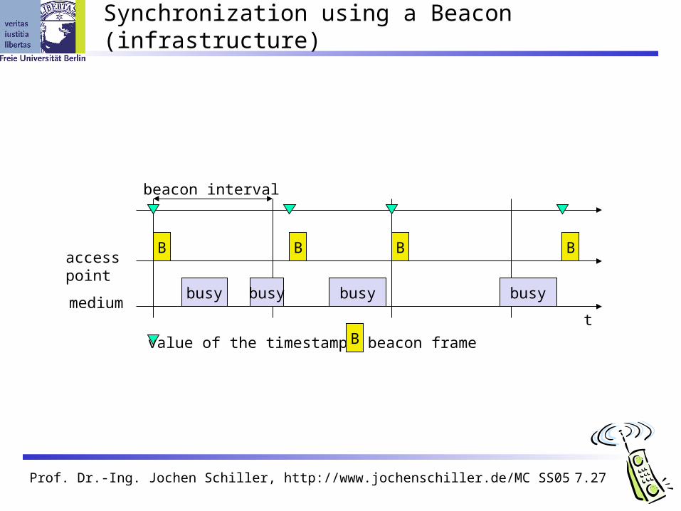
beacon interval
tmedium
accesspoint
busy
B
busy busy busy
B B B
value of the timestamp B beacon frame

Prof. Dr.-Ing. Jochen Schiller, http://www.jochenschiller.de/ MC SS05 7.28
Synchronization using a Beacon (ad-hoc)
tmedium
station1
busy
B1
beacon interval
busy busy busy
B1
value of the timestamp B beacon frame
station2
B2 B2
random delay

Prof. Dr.-Ing. Jochen Schiller, http://www.jochenschiller.de/ MC SS05 7.29
Power management
Idea: switch the transceiver off if not needed
States of a station: sleep and awake
Timing Synchronization Function (TSF) stations wake up at the same time
Infrastructure Traffic Indication Map (TIM)
list of unicast receivers transmitted by AP Delivery Traffic Indication Map (DTIM)
list of broadcast/multicast receivers transmitted by AP
Ad-hoc Ad-hoc Traffic Indication Map (ATIM)
announcement of receivers by stations buffering frames more complicated - no central AP collision of ATIMs possible (scalability?)

Prof. Dr.-Ing. Jochen Schiller, http://www.jochenschiller.de/ MC SS05 7.30
Power saving with wake-up patterns (infrastructure)
TIM interval
t
medium
accesspoint
busy
D
busy busy busy
T T D
T TIM D DTIM
DTIM interval
BB
B broadcast/multicast
station
awake
p PS poll
p
d
d
d data transmissionto/from the station
Prof. Dr.-Ing. Jochen Schiller, http://www.jochenschiller.de/ MC SS05 7.31
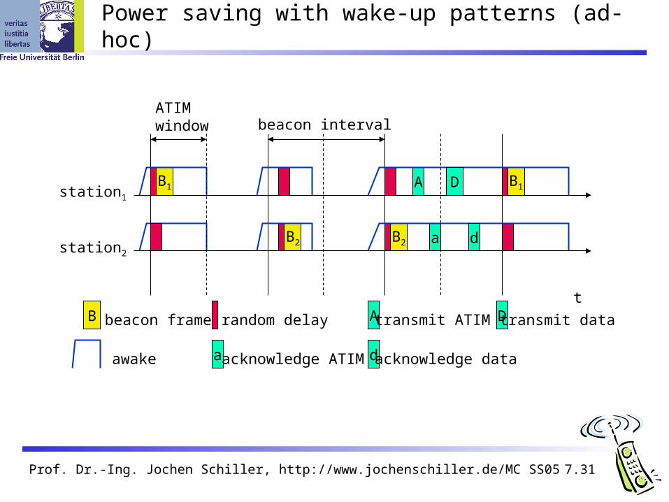
Power saving with wake-up patterns (ad-hoc)
awake
A transmit ATIM D transmit data
t
station1
B1 B1
B beacon frame
station2
B2 B2
random delay
A
a
D
d
ATIMwindow beacon interval
a acknowledge ATIM d acknowledge data
Prof. Dr.-Ing. Jochen Schiller, http://www.jochenschiller.de/ MC SS05 7.32
802.11 - Roaming
No or bad connection? Then perform:
Scanning scan the environment, i.e., listen into the medium for beacon signals or
send probes into the medium and wait for an answer
Reassociation Request station sends a request to one or several AP(s)
Reassociation Response success: AP has answered, station can now participate failure: continue scanning
AP accepts Reassociation Request signal the new station to the distribution system the distribution system updates its data base (i.e., location information) typically, the distribution system now informs the old AP so it can release
resources

Prof. Dr.-Ing. Jochen Schiller, http://www.jochenschiller.de/ MC SS05 7.33
WLAN: IEEE 802.11b
Data rate 1, 2, 5.5, 11 Mbit/s, depending on
SNR User data rate max. approx. 6
Mbit/s
Transmission range 300m outdoor, 30m indoor Max. data rate ~10m indoor
Frequency Free 2.4 GHz ISM-band
Security Limited, WEP insecure, SSID
Availability Many products, many vendors
Connection set-up time Connectionless/always on
Quality of Service Typ. Best effort, no guarantees
(unless polling is used, limited support in products)
Manageability Limited (no automated key
distribution, sym. Encryption)
Special Advantages/Disadvantages Advantage: many installed systems,
lot of experience, available worldwide, free ISM-band, many vendors, integrated in laptops, simple system
Disadvantage: heavy interference on ISM-band, no service guarantees, slow relative speed only

Prof. Dr.-Ing. Jochen Schiller, http://www.jochenschiller.de/ MC SS05 7.34
IEEE 802.11b – PHY frame formats
synchronization SFD signal service HEC payload
PLCP preamble PLCP header
128 16 8 8 16 variable bits
length
16
192 µs at 1 Mbit/s DBPSK 1, 2, 5.5 or 11 Mbit/s
short synch. SFD signal service HEC payload
PLCP preamble(1 Mbit/s, DBPSK)
PLCP header(2 Mbit/s, DQPSK)
56 16 8 8 16 variable bits
length
16
96 µs 2, 5.5 or 11 Mbit/s
Long PLCP PPDU format
Short PLCP PPDU format (optional)
Prof. Dr.-Ing. Jochen Schiller, http://www.jochenschiller.de/ MC SS05 7.35
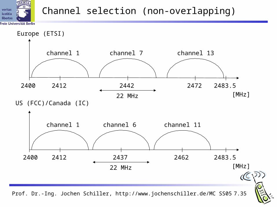
Channel selection (non-overlapping)
2400
[MHz]
2412 2483.52442 2472
channel 1 channel 7 channel 13
Europe (ETSI)
US (FCC)/Canada (IC)
2400
[MHz]
2412 2483.52437 2462
channel 1 channel 6 channel 11
22 MHz
22 MHz

Prof. Dr.-Ing. Jochen Schiller, http://www.jochenschiller.de/ MC SS05 7.36
WLAN: IEEE 802.11a
Data rate 6, 9, 12, 18, 24, 36, 48, 54 Mbit/s,
depending on SNR User throughput (1500 byte packets): 5.3
(6), 18 (24), 24 (36), 32 (54) 6, 12, 24 Mbit/s mandatory
Transmission range 100m outdoor, 10m indoor
E.g., 54 Mbit/s up to 5 m, 48 up to 12 m, 36 up to 25 m, 24 up to 30m, 18 up to 40 m, 12 up to 60 m
Frequency Free 5.15-5.25, 5.25-5.35, 5.725-5.825
GHz ISM-band
Security Limited, WEP insecure, SSID
Availability Some products, some vendors
Connection set-up time Connectionless/always on
Quality of Service Typ. best effort, no guarantees (same as
all 802.11 products)
Manageability Limited (no automated key distribution,
sym. Encryption)
Special Advantages/Disadvantages Advantage: fits into 802.x standards, free
ISM-band, available, simple system, uses less crowded 5 GHz band
Disadvantage: stronger shading due to higher frequency, no QoS

Prof. Dr.-Ing. Jochen Schiller, http://www.jochenschiller.de/ MC SS05 7.37
IEEE 802.11a – PHY frame format
rate service payload
variable bits
6 Mbit/s
PLCP preamble signal data
symbols12 1 variable
reserved length tailparity tail pad
616611214 variable
6, 9, 12, 18, 24, 36, 48, 54 Mbit/s
PLCP header

Prof. Dr.-Ing. Jochen Schiller, http://www.jochenschiller.de/ MC SS05 7.38
Operating channels for 802.11a / US U-NII
5150 [MHz]5180 53505200
36 44
16.6 MHz
center frequency = 5000 + 5*channel number [MHz]
channel40 48 52 56 60 64
149 153 157 161
5220 5240 5260 5280 5300 5320
5725 [MHz]5745 58255765
16.6 MHz
channel
5785 5805
Prof. Dr.-Ing. Jochen Schiller, http://www.jochenschiller.de/ MC SS05 7.39
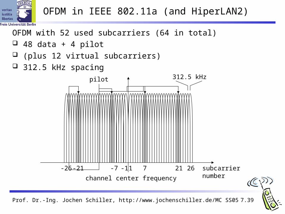
OFDM in IEEE 802.11a (and HiperLAN2)
OFDM with 52 used subcarriers (64 in total) 48 data + 4 pilot (plus 12 virtual subcarriers) 312.5 kHz spacing
subcarriernumber
1 7 21 26-26 -21 -7 -1
channel center frequency
312.5 kHzpilot

Prof. Dr.-Ing. Jochen Schiller, http://www.jochenschiller.de/ MC SS05 7.40
WLAN: IEEE 802.11 – future developments (03/2005)
802.11c: Bridge Support Definition of MAC procedures to support bridges as extension to 802.1D
802.11d: Regulatory Domain Update Support of additional regulations related to channel selection, hopping sequences
802.11e: MAC Enhancements – QoS Enhance the current 802.11 MAC to expand support for applications with Quality of
Service requirements, and in the capabilities and efficiency of the protocol Definition of a data flow (“connection”) with parameters like rate, burst, period… Additional energy saving mechanisms and more efficient retransmission
802.11f: Inter-Access Point Protocol Establish an Inter-Access Point Protocol for data exchange via the distribution
system Currently unclear to which extend manufacturers will follow this suggestion
802.11g: Data Rates > 20 Mbit/s at 2.4 GHz; 54 Mbit/s, OFDM Successful successor of 802.11b, performance loss during mixed operation with 11b
802.11h: Spectrum Managed 802.11a Extension for operation of 802.11a in Europe by mechanisms like channel
measurement for dynamic channel selection (DFS, Dynamic Frequency Selection) and power control (TPC, Transmit Power Control)

Prof. Dr.-Ing. Jochen Schiller, http://www.jochenschiller.de/ MC SS05 7.41
WLAN: IEEE 802.11– future developments (03/2005)
802.11i: Enhanced Security Mechanisms Enhance the current 802.11 MAC to provide improvements in security. TKIP enhances the insecure WEP, but remains compatible to older WEP systems AES provides a secure encryption method and is based on new hardware
802.11j: Extensions for operations in Japan Changes of 802.11a for operation at 5GHz in Japan using only half the channel
width at larger range802.11k: Methods for channel measurements
Devices and access points should be able to estimate channel quality in order to be able to choose a better access point of channel
802.11m: Updates of the 802.11 standards802.11n: Higher data rates above 100Mbit/s
Changes of PHY and MAC with the goal of 100Mbit/s at MAC SAP MIMO antennas (Multiple Input Multiple Output), up to 600Mbit/s are currently
feasible However, still a large overhead due to protocol headers and inefficient mechanisms
802.11p: Inter car communications Communication between cars/road side and cars/cars Planned for relative speeds of min. 200km/h and ranges over 1000m Usage of 5.850-5.925GHz band in North America

Prof. Dr.-Ing. Jochen Schiller, http://www.jochenschiller.de/ MC SS05 7.42
WLAN: IEEE 802.11– future developments (03/2005)
802.11r: Faster Handover between BSS Secure, fast handover of a station from one AP to another within an ESS Current mechanisms (even newer standards like 802.11i) plus incompatible devices from
different vendors are massive problems for the use of, e.g., VoIP in WLANs Handover should be feasible within 50ms in order to support multimedia applications efficiently
802.11s: Mesh Networking Design of a self-configuring Wireless Distribution System (WDS) based on 802.11 Support of point-to-point and broadcast communication across several hops
802.11t: Performance evaluation of 802.11 networks Standardization of performance measurement schemes
802.11u: Interworking with additional external networks802.11v: Network management
Extensions of current management functions, channel measurements Definition of a unified interface
802.11w: Securing of network control Classical standards like 802.11, but also 802.11i protect only data frames, not the control
frames. Thus, this standard should extend 802.11i in a way that, e.g., no control frames can be forged.
Note: Not all “standards” will end in products, many ideas get stuck at working group levelInfo: www.ieee802.org/11/, 802wirelessworld.com, standards.ieee.org/getieee802/
Prof. Dr.-Ing. Jochen Schiller, http://www.jochenschiller.de/ MC SS05 7.43
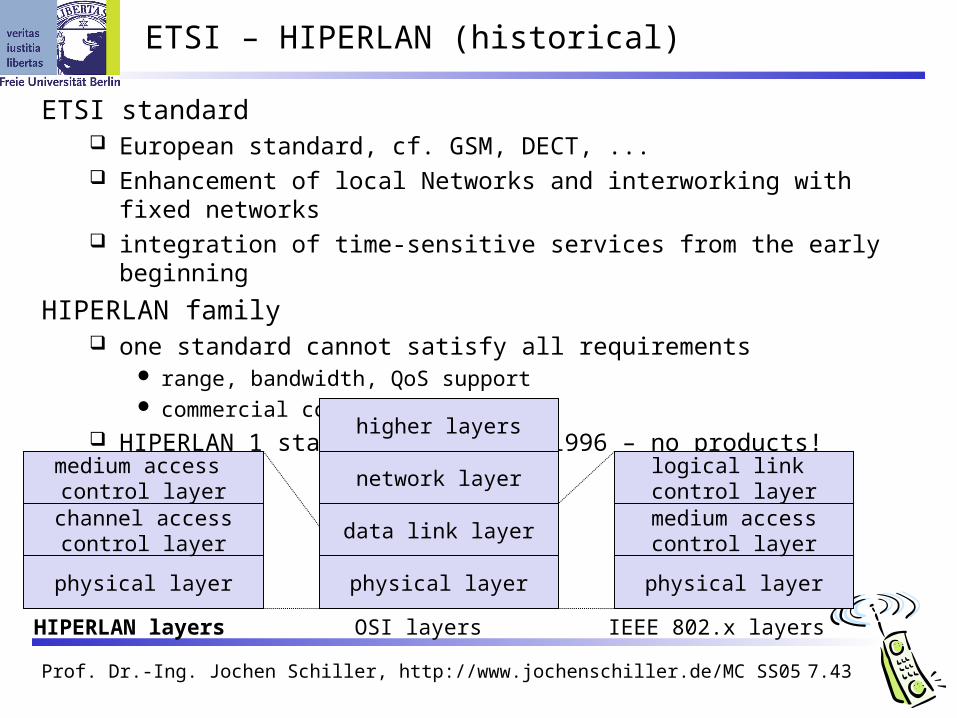
ETSI – HIPERLAN (historical)
ETSI standard European standard, cf. GSM, DECT, ... Enhancement of local Networks and interworking with fixed networks integration of time-sensitive services from the early beginning
HIPERLAN family one standard cannot satisfy all requirements
range, bandwidth, QoS support commercial constraints
HIPERLAN 1 standardized since 1996 – no products!
physical layer
channel accesscontrol layer
medium access control layer
physical layer
data link layer
HIPERLAN layers OSI layers
network layer
higher layers
physical layer
medium accesscontrol layer
logical link control layer
IEEE 802.x layers

Prof. Dr.-Ing. Jochen Schiller, http://www.jochenschiller.de/ MC SS05 7.44
Overview: original HIPERLAN protocol family
HIPERLAN 1 HIPERLAN 2 HIPERLAN 3 HIPERLAN 4
Application wireless LAN access to ATMfixed networks
wireless localloop
point-to-pointwireless ATMconnections
Frequency 5.1-5.3GHz 17.2-17.3GHz
Topology decentralized ad-hoc/infrastructure
cellular,centralized
point-to-multipoint
point-to-point
Antenna omni-directional directionalRange 50 m 50-100 m 5000 m 150 mQoS statistical ATM traffic classes (VBR, CBR, ABR, UBR)Mobility <10m/s stationaryInterface conventional LAN ATM networks
Data rate 23.5 Mbit/s >20 Mbit/s 155 Mbit/sPowerconservation
yes not necessary
HIPERLAN 1 never reached product status, the other standards have been renamed/modfied !
Prof. Dr.-Ing. Jochen Schiller, http://www.jochenschiller.de/ MC SS05 7.45
HIPERLAN 1 - Characteristics
Data transmission point-to-point, point-to-multipoint, connectionless 23.5 Mbit/s, 1 W power, 2383 byte max. packet size
Services asynchronous and time-bounded services with hierarchical priorities compatible with ISO MAC
Topology infrastructure or ad-hoc networks transmission range can be larger then coverage of a single node
(„forwarding“ integrated in mobile terminals)
Further mechanisms power saving, encryption, checksums

Prof. Dr.-Ing. Jochen Schiller, http://www.jochenschiller.de/ MC SS05 7.46
HIPERLAN 1 - Physical layer
Scope modulation, demodulation, bit and frame synchronization forward error correction mechanisms measurements of signal strength channel sensing
Channels 3 mandatory and 2 optional channels (with their carrier frequencies) mandatory
channel 0: 5.1764680 GHz channel 1: 5.1999974 GHz channel 2: 5.2235268 GHz
optional channel 3: 5.2470562 GHz channel 4: 5.2705856 GHz
Prof. Dr.-Ing. Jochen Schiller, http://www.jochenschiller.de/ MC SS05 7.47
HIPERLAN 1 - Physical layer frames
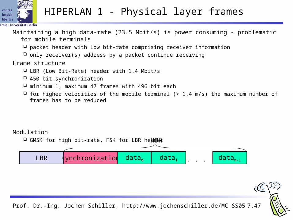
Maintaining a high data-rate (23.5 Mbit/s) is power consuming - problematic for mobile terminals packet header with low bit-rate comprising receiver information only receiver(s) address by a packet continue receiving
Frame structure LBR (Low Bit-Rate) header with 1.4 Mbit/s 450 bit synchronization minimum 1, maximum 47 frames with 496 bit each for higher velocities of the mobile terminal (> 1.4 m/s) the maximum number of frames has to be
reduced
Modulation GMSK for high bit-rate, FSK for LBR header
LBR synchronization data0 data1 datam-1. . .
HBR
Prof. Dr.-Ing. Jochen Schiller, http://www.jochenschiller.de/ MC SS05 7.48
HIPERLAN 1 - CAC sublayer
Channel Access Control (CAC) assure that terminal does not access forbidden channels priority scheme, access with EY-NPMA
Priorities 5 priority levels for QoS support QoS is mapped onto a priority level with the help of the packet
lifetime (set by an application) if packet lifetime = 0 it makes no sense to forward the packet to the
receiver any longer standard start value 500ms, maximum 16000ms if a terminal cannot send the packet due to its current priority, waiting
time is permanently subtracted from lifetime based on packet lifetime, waiting time in a sender and number of hops to
the receiver, the packet is assigned to one out of five priorities the priority of waiting packets, therefore, rises automatically
Prof. Dr.-Ing. Jochen Schiller, http://www.jochenschiller.de/ MC SS05 7.49
prioritization
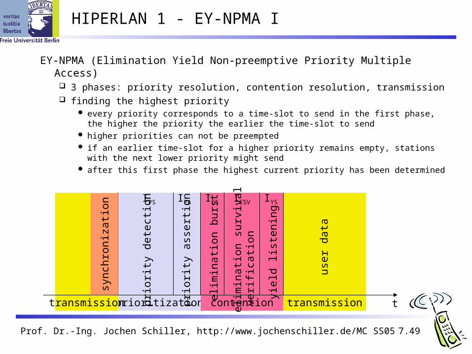
HIPERLAN 1 - EY-NPMA I
EY-NPMA (Elimination Yield Non-preemptive Priority Multiple Access) 3 phases: priority resolution, contention resolution, transmission finding the highest priority
every priority corresponds to a time-slot to send in the first phase, the higher the priority the earlier the time-slot to send
higher priorities can not be preempted if an earlier time-slot for a higher priority remains empty, stations with the
next lower priority might send after this first phase the highest current priority has been determined
contention transmissiontransmission
sync
hron
izat
ion
prio
rity
dete
ctio
n
prio
rity
asse
rtio
n
t
user
dat
a
elim
inat
ion
burs
t
elim
inat
ion
surv
ival
ver
ifica
tion
yiel
d lis
teni
ng
IYSIPS IPA IES IESV
Prof. Dr.-Ing. Jochen Schiller, http://www.jochenschiller.de/ MC SS05 7.50
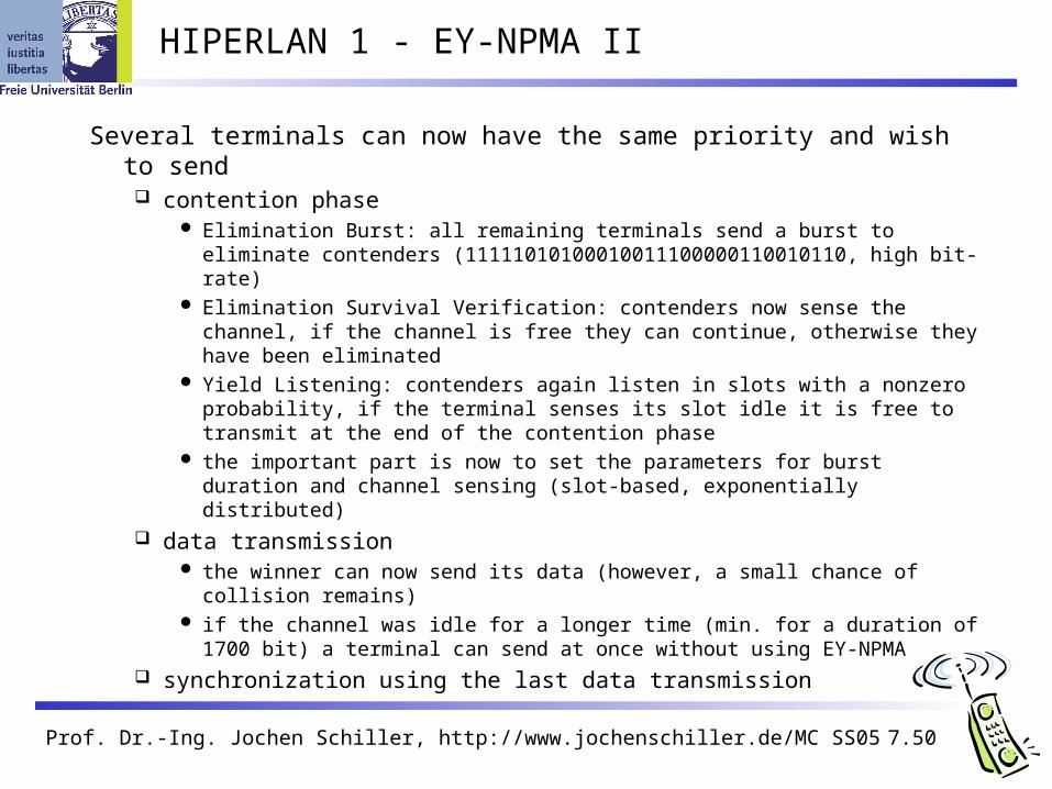
HIPERLAN 1 - EY-NPMA II
Several terminals can now have the same priority and wish to send contention phase
Elimination Burst: all remaining terminals send a burst to eliminate contenders (11111010100010011100000110010110, high bit- rate)
Elimination Survival Verification: contenders now sense the channel, if the channel is free they can continue, otherwise they have been eliminated
Yield Listening: contenders again listen in slots with a nonzero probability, if the terminal senses its slot idle it is free to transmit at the end of the contention phase
the important part is now to set the parameters for burst duration and channel sensing (slot-based, exponentially distributed)
data transmission the winner can now send its data (however, a small chance of collision
remains) if the channel was idle for a longer time (min. for a duration of 1700 bit) a
terminal can send at once without using EY-NPMA synchronization using the last data transmission
Prof. Dr.-Ing. Jochen Schiller, http://www.jochenschiller.de/ MC SS05 7.51
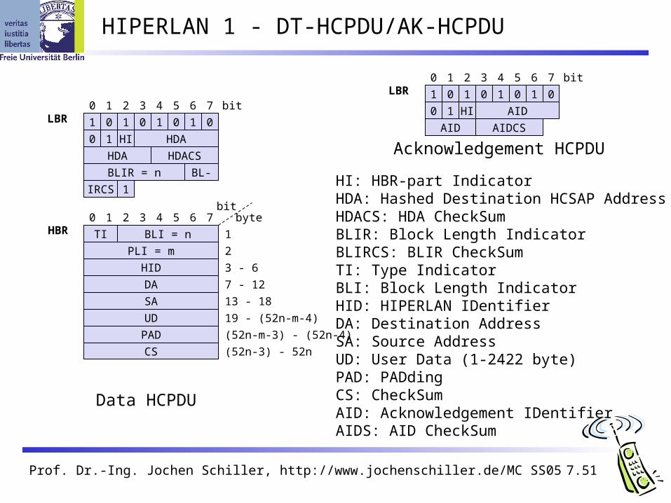
HIPERLAN 1 - DT-HCPDU/AK-HCPDU
1 0 1 0 1 0 1 0
0 1 HI HDA
HDA HDACS
BLIR = n
1
BL-
IRCS
LBR0 1 2 3 4 5 6 7 bit
HBR0 1 2 3 4 5 6 7
bit
TI BLI = n
byte
1
PLI = m
HID
2
3 - 6
DA 7 - 12
SA 13 - 18
UD 19 - (52n-m-4)
PAD (52n-m-3) - (52n-4)
CS (52n-3) - 52n
1 0 1 0 1 0 1 0
0 1 HI AID
AID AIDCS
LBR0 1 2 3 4 5 6 7 bit
Data HCPDU
Acknowledgement HCPDU
HI: HBR-part IndicatorHDA: Hashed Destination HCSAP AddressHDACS: HDA CheckSumBLIR: Block Length IndicatorBLIRCS: BLIR CheckSumTI: Type IndicatorBLI: Block Length IndicatorHID: HIPERLAN IDentifierDA: Destination AddressSA: Source AddressUD: User Data (1-2422 byte)PAD: PADdingCS: CheckSumAID: Acknowledgement IDentifierAIDS: AID CheckSum
Prof. Dr.-Ing. Jochen Schiller, http://www.jochenschiller.de/ MC SS05 7.52
HIPERLAN 1 - MAC layer
Compatible to ISO MAC
Supports time-bounded services via a priority scheme
Packet forwarding support of directed (point-to-point) forwarding and broadcast forwarding (if
no path information is available) support of QoS while forwarding
Encryption mechanisms mechanisms integrated, but without key management
Power conservation mechanisms mobile terminals can agree upon awake patterns (e.g., periodic wake-ups
to receive data) additionally, some nodes in the networks must be able to buffer data for
sleeping terminals and to forward them at the right time (so called stores)
Prof. Dr.-Ing. Jochen Schiller, http://www.jochenschiller.de/ MC SS05 7.53
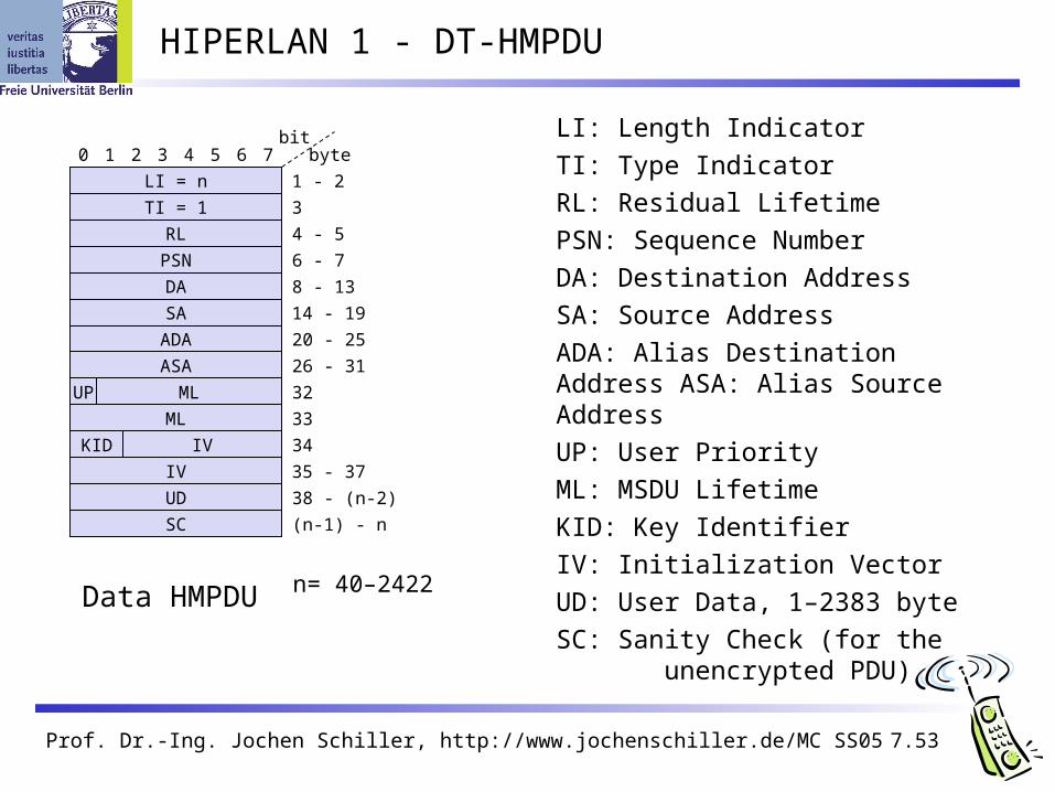
HIPERLAN 1 - DT-HMPDU
LI: Length Indicator
TI: Type Indicator
RL: Residual Lifetime
PSN: Sequence Number
DA: Destination Address
SA: Source Address
ADA: Alias Destination Address ASA: Alias Source Address
UP: User Priority
ML: MSDU Lifetime
KID: Key Identifier
IV: Initialization Vector
UD: User Data, 1–2383 byte
SC: Sanity Check (for the unencrypted PDU)
n= 40–2422
0 1 2 3 4 5 6 7bit
LI = n
byte
1 - 2
TI = 1
RL
3
4 - 5
PSN 6 - 7
DA 8 - 13
SA 14 - 19
ADA 20 - 25
ASA 26 - 31
UP ML
ML
KID
IV
IV
UD
SC
32
33
34
35 - 37
38 - (n-2)
(n-1) - n
Data HMPDU
Prof. Dr.-Ing. Jochen Schiller, http://www.jochenschiller.de/ MC SS05 7.54
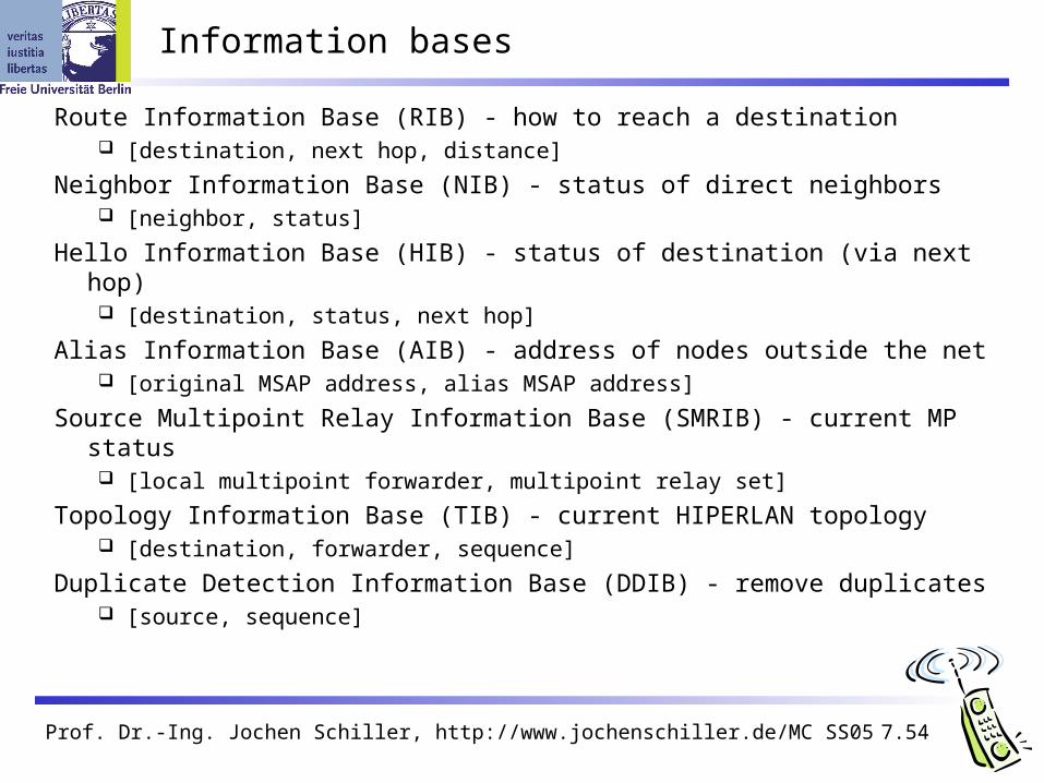
Information bases
Route Information Base (RIB) - how to reach a destination [destination, next hop, distance]
Neighbor Information Base (NIB) - status of direct neighbors [neighbor, status]
Hello Information Base (HIB) - status of destination (via next hop) [destination, status, next hop]
Alias Information Base (AIB) - address of nodes outside the net [original MSAP address, alias MSAP address]
Source Multipoint Relay Information Base (SMRIB) - current MP status [local multipoint forwarder, multipoint relay set]
Topology Information Base (TIB) - current HIPERLAN topology [destination, forwarder, sequence]
Duplicate Detection Information Base (DDIB) - remove duplicates [source, sequence]

Prof. Dr.-Ing. Jochen Schiller, http://www.jochenschiller.de/ MC SS05 7.55
Ad-hoc networks using HIPERLAN 1
neighborhood(i.e., within radio range)
Information Bases (IB):RIB: RouteNIB: Neighbor HIB: Hello AIB: AliasSMRIB: Source Multipoint RelayTIB: TopologyDDIB: Duplicate Detection
RIBNIBHIBAIBSMRIBTIBDDIB
RIBNIBHIBAIBSMRIBTIBDDIB
RIBNIBHIBAIBSMRIBTIBDDIB
RIBNIBHIBAIBDDIB
RIBNIBHIBAIBDDIB
RIBNIBHIBAIBDDIB
12
34
5
6
Forwarder
Forwarder
Forwarder
Prof. Dr.-Ing. Jochen Schiller, http://www.jochenschiller.de/ MC SS05 7.56
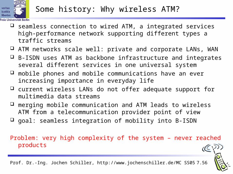
Some history: Why wireless ATM?
seamless connection to wired ATM, a integrated services high-performance network supporting different types a traffic streams
ATM networks scale well: private and corporate LANs, WAN B-ISDN uses ATM as backbone infrastructure and integrates several
different services in one universal system mobile phones and mobile communications have an ever increasing
importance in everyday life current wireless LANs do not offer adequate support for multimedia
data streams merging mobile communication and ATM leads to wireless ATM from a
telecommunication provider point of view goal: seamless integration of mobility into B-ISDN
Problem: very high complexity of the system – never reached products

Prof. Dr.-Ing. Jochen Schiller, http://www.jochenschiller.de/ MC SS05 7.57
ATM - basic principle
favored by the telecommunication industry for advanced high-performance networks, e.g., B-ISDN, as transport mechanism
statistical (asynchronous, on demand) TDM (ATDM, STDM) cell header determines the connection the user data belongs to mixing of different cell-rates is possible
different bit-rates, constant or variable, feasible interesting for data sources with varying bit-rate:
e.g., guaranteed minimum bit-rate additionally bursty traffic if allowed by the network
ATM cell: 5 48 [byte]
connection identifier, checksum etc.
cell header user data
Prof. Dr.-Ing. Jochen Schiller, http://www.jochenschiller.de/ MC SS05 7.58
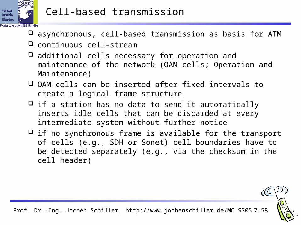
Cell-based transmission
asynchronous, cell-based transmission as basis for ATM continuous cell-stream additional cells necessary for operation and maintenance of the network
(OAM cells; Operation and Maintenance) OAM cells can be inserted after fixed intervals to create a logical frame
structure if a station has no data to send it automatically inserts idle cells that can be
discarded at every intermediate system without further notice if no synchronous frame is available for the transport of cells (e.g., SDH or
Sonet) cell boundaries have to be detected separately (e.g., via the checksum in the cell header)
Prof. Dr.-Ing. Jochen Schiller, http://www.jochenschiller.de/ MC SS05 7.59
physical layer
ATM layer
ATM adaptation layer
higherlayers
higherlayers
control plane
layer managem
ent
plane managem
ent
user plane
planes
layers
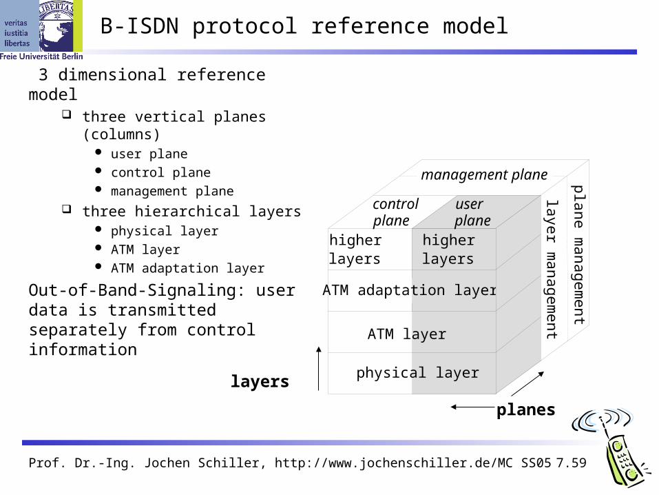
B-ISDN protocol reference model
3 dimensional reference model three vertical planes (columns)
user plane control plane management plane
three hierarchical layers physical layer ATM layer ATM adaptation layer
Out-of-Band-Signaling: user data is transmitted separately from control information
management plane

Prof. Dr.-Ing. Jochen Schiller, http://www.jochenschiller.de/ MC SS05 7.60
ATM layers
Physical layer, consisting of two sub-layers physical medium dependent sub-layer
coding bit timing transmission
transmission convergence sub-layer HEC (Header Error Correction) sequence generation and verification transmission frame adaptation, generation, and recovery cell delineation, cell rate decoupling
ATM layer cell multiplexing/demultiplexing VPI/VCI translation cell header generation and verification GFC (Generic Flow Control)
ATM adaptation layer (AAL)

Prof. Dr.-Ing. Jochen Schiller, http://www.jochenschiller.de/ MC SS05 7.61
ATM adaptation layer (AAL)
Provides different service classes on top of ATM based on: bit rate:
constant bit rate: e.g. traditional telephone line variable bit rate: e.g. data communication, compressed video
time constraints between sender and receiver: with time constraints: e.g. real-time applications, interactive voice and video without time constraints: e.g. mail, file transfer
mode of connection: connection oriented or connectionless
AAL consists of two sub-layers: Convergence Sublayer (CS): service dependent adaptation
Common Part Convergence Sublayer (CPCS) Service Specific Convergence Sublayer (SSCS)
Segmentation and Reassembly Sublayer (SAR) sub-layers can be empty

Prof. Dr.-Ing. Jochen Schiller, http://www.jochenschiller.de/ MC SS05 7.62
ATM and AAL connections
ATM layer: service independent transport of ATM cells multiplex and demultiplex functionality
AAL layer: support of different services
physicallayer
ATM
AAL
physicallayer
ATM
AAL
end-system A end-system B
ATM network
service dependentAAL connections
service independentATM connections
application

Prof. Dr.-Ing. Jochen Schiller, http://www.jochenschiller.de/ MC SS05 7.63
ATM Forum Wireless ATM Working Group
ATM Forum founded the Wireless ATM Working Group June 1996 Task: development of specifications to enable the use of ATM
technology also for wireless networks with a large coverage of current network scenarios (private and public, local and global)
compatibility to existing ATM Forum standards important it should be possible to easily upgrade existing ATM networks with
mobility functions and radio access two sub-groups of work items
Mobile ATM Protocol Extensions handover signaling location management mobile routing traffic and QoS Control network management
Radio Access Layer (RAL) Protocols radio access layer wireless media access control wireless data link control radio resource control handover issues

Prof. Dr.-Ing. Jochen Schiller, http://www.jochenschiller.de/ MC SS05 7.64
WATM services
Office environment multimedia conferencing, online multimedia database access
Universities, schools, training centers distance learning, teaching
Industry database connection, surveillance, real-time factory management
Hospitals reliable, high-bandwidth network, medical images, remote monitoring
Home high-bandwidth interconnect of devices (TV, CD, PC, ...)
Networked vehicles trucks, aircraft etc. interconnect, platooning, intelligent roads

Prof. Dr.-Ing. Jochen Schiller, http://www.jochenschiller.de/ MC SS05 7.65
WATM components
WMT (Wireless Mobile ATM Terminal)
RAS (Radio Access System)
EMAS-E (End-user Mobility-supporting ATM Switch - Edge)
EMAS-N (End-user Mobility-supporting ATM Switch - Network)
M-NNI (Network-to-Network Interface with Mobility support)
LS (Location Server)
AUS (Authentication Server)

Prof. Dr.-Ing. Jochen Schiller, http://www.jochenschiller.de/ MC SS05 7.66
Reference model
WMT
WMT
EMAS-E
EMAS-N
EMAS-N
M-NNI
RAS
RAS
LSAUS

Prof. Dr.-Ing. Jochen Schiller, http://www.jochenschiller.de/ MC SS05 7.67
User plane protocol layers
WATMterminaladapter
MATMtermi-
nalRAS
EMAS-E
EMAS-N
ATM-Switch
fixedend
system
radio segment fixed network segment
RAL
ATM
PHY PHY
ATM
PHY
AAL
userprocess
ATM
AAL
user process
ATM-CL
ATM
RAL PHY
ATM-CL
ATM
PHY PHY
ATM
PHY PHY

Prof. Dr.-Ing. Jochen Schiller, http://www.jochenschiller.de/ MC SS05 7.68
Control plane protocol layers
ATM
PHY
SAAL
SIG,UNI
RAL
M-ATM
SAAL
SIG,M-UNI
ATM-CL
ATM
RAL PHY
ATM-CL
ATM
PHY PHY
SAAL
SIG,M-UNI,M-PNNI
ATM
PHY PHY
SAAL
SIG,M-PNNI
ATM
PHY PHY
SAAL
SIG,PNNI,UNI
WATMterminaladapter
MATMtermi-
nalRAS
EMAS-E
EMAS-N
ATM-Switch
fixedend
system
radio segment fixed network segment

Prof. Dr.-Ing. Jochen Schiller, http://www.jochenschiller.de/ MC SS05 7.69
Reference model with further access scenarios I
1: wireless ad-hoc ATM network
2: wireless mobile ATM terminals
3: mobile ATM terminals
4: mobile ATM switches
5: fixed ATM terminals
6: fixed wireless ATM terminals
WMT: wireless mobile terminal
WT: wireless terminal
MT: mobile terminal
T: terminal
AP: access point
EMAS: end-user mobility supporting ATM switch (-E: edge, -N: network)
NMAS: network mobility supporting ATM switch
MS: mobile ATM switch

Prof. Dr.-Ing. Jochen Schiller, http://www.jochenschiller.de/ MC SS05 7.70
Reference model with further access scenarios II
RAS ACT WMT
WMT
NMAS
RAS
RASMS
T
EMAS-EMT
WTRAS
EMAS-N TRAS
EMAS-EWMT
1
2
3
4
5
6

Prof. Dr.-Ing. Jochen Schiller, http://www.jochenschiller.de/ MC SS05 7.71
BRAN – Broadband Radio Access Networks
Motivation deregulation, privatization, new companies, new services How to reach the customer?
alternatives: xDSL, cable, satellite, radio
Radio access flexible (supports traffic mix, multiplexing for higher efficiency, can be
asymmetrical) quick installation economic (incremental growth possible)
Market private customers (Internet access, tele-xy...) small and medium sized business (Internet, MM conferencing, VPN)
Scope of standardization access networks, indoor/campus mobility, 25-155 Mbit/s, 50 m-5 km coordination with ATM Forum, IETF, ETSI, IEEE, ....

Prof. Dr.-Ing. Jochen Schiller, http://www.jochenschiller.de/ MC SS05 7.72
Broadband network types
Common characteristics ATM QoS (CBR, VBR, UBR, ABR)
HIPERLAN/2 short range (< 200 m), indoor/campus, 25 Mbit/s user data rate access to telecommunication systems, multimedia applications, mobility
(<10 m/s)
HIPERACCESS wider range (< 5 km), outdoor, 25 Mbit/s user data rate fixed radio links to customers (“last mile”), alternative to xDSL or cable
modem, quick installation Several (proprietary) products exist with 155 Mbit/s plus QoS
HIPERLINK – currently no activities intermediate link, 155 Mbit/s connection of HIPERLAN access points or connection between
HIPERACCESS nodes

Prof. Dr.-Ing. Jochen Schiller, http://www.jochenschiller.de/ MC SS05 7.73
BRAN and legacy networks
Independence BRAN as access network independent from the fixed network Interworking of TCP/IP and ATM under study
Layered model Network Convergence Sub-layer as superset of all requirements for IP and
ATM
core networkATM
core networkIP
network convergence sublayer
BRAN data link control
BRAN PHY-1 BRAN PHY-2 ...
Coordination IETF (TCP/IP) ATM forum (ATM) ETSI (UMTS) CEPT, ITU-R, ... (radio frequencies)

Prof. Dr.-Ing. Jochen Schiller, http://www.jochenschiller.de/ MC SS05 7.74
HiperLAN2 (historical)
Official name: BRAN HIPERLAN Type 2 H/2, HIPERLAN/2 also used
High data rates for users More efficient than 802.11a
Connection oriented
QoS support
Dynamic frequency selection
Security support Strong encryption/authentication
Mobility support
Network and application independent convergence layers for Ethernet, IEEE 1394, ATM, 3G
Power save modes
Plug and PlayNo products – but several mechanisms have beenAdopted by other standards (e.g. 802.11a)

Prof. Dr.-Ing. Jochen Schiller, http://www.jochenschiller.de/ MC SS05 7.75
2
3
1
AP
HiperLAN2 architecture and handover scenarios
APT APC CoreNetwork
(Ethernet,Firewire,
ATM,UMTS)APT
APT
APC
AP
MT4
MT3
MT2
MT1

Prof. Dr.-Ing. Jochen Schiller, http://www.jochenschiller.de/ MC SS05 7.76
Centralized vs. direct mode
MT1
AP/CCAP
MT2
data
control control
MT1 MT2
data
control
Centralized Direct
MT1 MT2 +CCdata
control

Prof. Dr.-Ing. Jochen Schiller, http://www.jochenschiller.de/ MC SS05 7.77
HiperLAN2 protocol stack
Higher layers
Convergence layer
Data link control - basic data
transport functionScope of HiperLAN2standards
DLC controlSAP
DLC userSAP
Radio link control sublayer
Physical layer
Radioresourcecontrol
Assoc.control
DLCconn.
controlError
controlRadio link control
Medium access control

Prof. Dr.-Ing. Jochen Schiller, http://www.jochenschiller.de/ MC SS05 7.78
Physical layer reference configuration
scrambling FEC coding interleaving
mapping OFDMPHY bursts
(PPDU)
PDU train from DLC(PSDU)
radiotransmitter
Prof. Dr.-Ing. Jochen Schiller, http://www.jochenschiller.de/ MC SS05 7.79
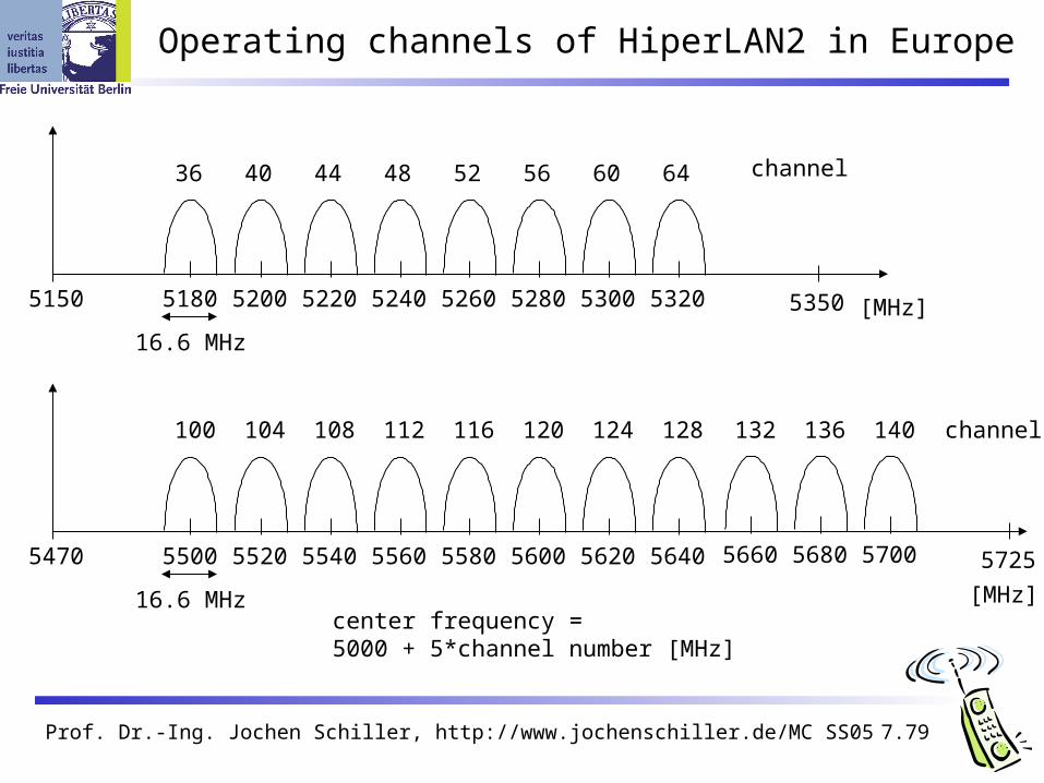
Operating channels of HiperLAN2 in Europe
5150 [MHz]5180 53505200
36 44
16.6 MHz
center frequency = 5000 + 5*channel number [MHz]
channel40 48 52 56 60 64
5220 5240 5260 5280 5300 5320
5470
[MHz]
5500 57255520
100 108
16.6 MHz
channel104 112 116 120 124 128
5540 5560 5580 5600 5620 5640
132 136 140
5660 5680 5700
Prof. Dr.-Ing. Jochen Schiller, http://www.jochenschiller.de/ MC SS05 7.80
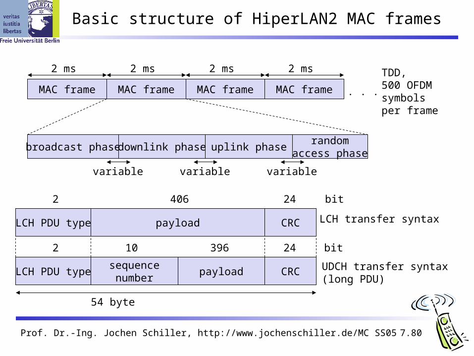
Basic structure of HiperLAN2 MAC frames
MAC frame MAC frame MAC frame MAC frame
2 ms 2 ms 2 ms 2 ms
broadcast phase downlink phase uplink phaserandom
access phase
. . .
TDD, 500 OFDMsymbolsper frame
variable variable variable
LCH PDU typesequencenumber
payload CRC UDCH transfer syntax(long PDU)
54 byte
2 10 396 24 bit
LCH PDU type payload CRC
2 406 24
LCH transfer syntax
bit
Prof. Dr.-Ing. Jochen Schiller, http://www.jochenschiller.de/ MC SS05 7.81
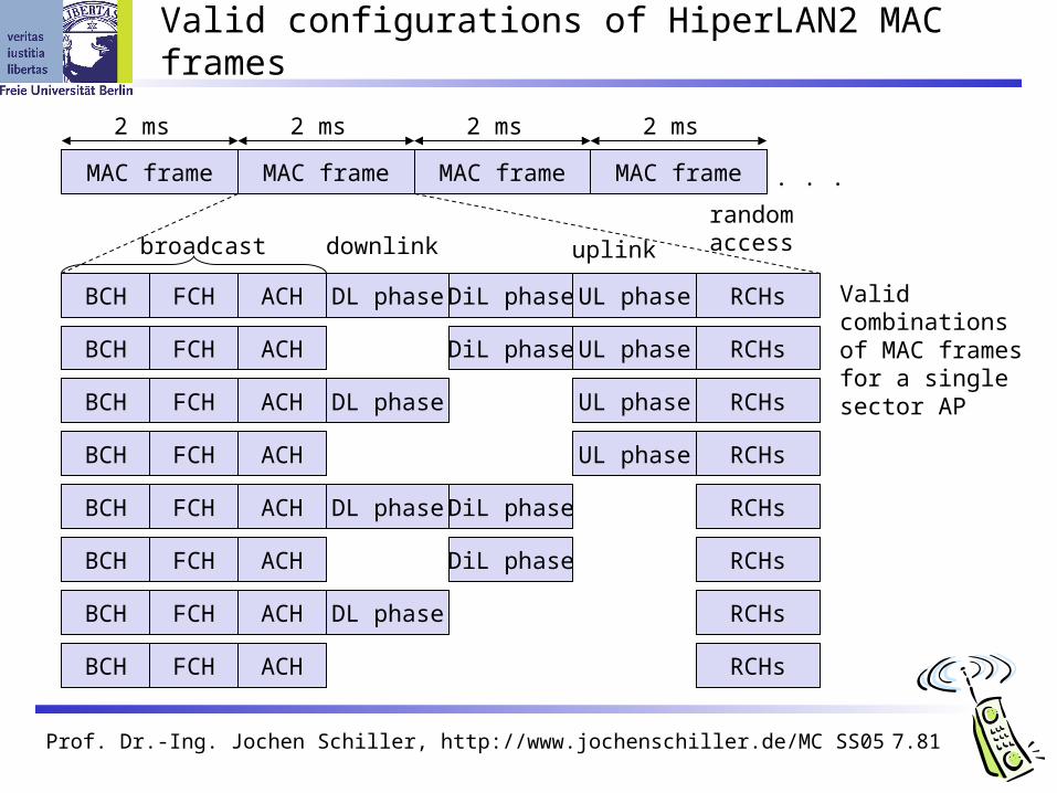
Valid configurations of HiperLAN2 MAC frames
MAC frame MAC frame MAC frame MAC frame
2 ms 2 ms 2 ms 2 ms
BCH FCH ACH DL phase DiL phase UL phase RCHs
. . .
BCH FCH ACH DiL phase UL phase RCHs
BCH FCH ACH DL phase UL phase RCHs
BCH FCH ACH UL phase RCHs
BCH FCH ACH DL phase DiL phase RCHs
BCH FCH ACH DiL phase RCHs
BCH FCH ACH DL phase RCHs
BCH FCH ACH RCHs
Validcombinationsof MAC framesfor a single sector AP
broadcast downlink uplink
randomaccess

Prof. Dr.-Ing. Jochen Schiller, http://www.jochenschiller.de/ MC SS05 7.82
Mapping of logical and transport channels
BCCH FCCH RFCH LCCH RBCH DCCH UDCH UBCH UMCH
BCH FCH ACH SCH LCH
downlink
UDCH DCCH LCCH ASCH
SCHLCH RCH
uplink
UDCH UBCH UMCH
LCH
DCCH RBCH
SCH
LCCH
direct link
Prof. Dr.-Ing. Jochen Schiller, http://www.jochenschiller.de/ MC SS05 7.83
Bluetooth
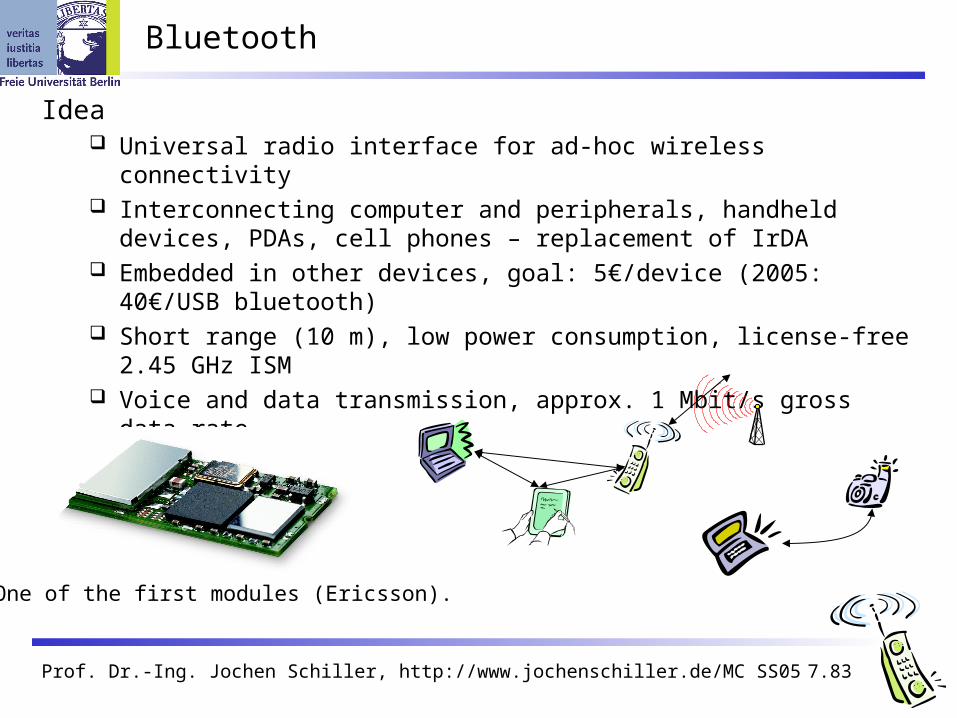
Idea Universal radio interface for ad-hoc wireless connectivity Interconnecting computer and peripherals, handheld devices, PDAs, cell
phones – replacement of IrDA Embedded in other devices, goal: 5€/device (2005: 40€/USB bluetooth) Short range (10 m), low power consumption, license-free 2.45 GHz ISM Voice and data transmission, approx. 1 Mbit/s gross data rate
One of the first modules (Ericsson).
Prof. Dr.-Ing. Jochen Schiller, http://www.jochenschiller.de/ MC SS05 7.84
Bluetooth
History 1994: Ericsson (Mattison/Haartsen), “MC-link” project Renaming of the project: Bluetooth according to Harald “Blåtand” Gormsen
[son of Gorm], King of Denmark in the 10th century 1998: foundation of Bluetooth SIG, www.bluetooth.org 1999: erection of a rune stone at Ercisson/Lund ;-) 2001: first consumer products for mass market, spec. version 1.1 released 2005: 5 million chips/week
Special Interest Group Original founding members: Ericsson, Intel, IBM, Nokia, Toshiba Added promoters: 3Com, Agere (was: Lucent), Microsoft, Motorola > 2500 members Common specification and certification of products
(was: )

Prof. Dr.-Ing. Jochen Schiller, http://www.jochenschiller.de/ MC SS05 7.85
History and hi-tech…
1999:Ericsson mobile communications AB reste denna sten till minne av Harald Blåtand, som fick ge sitt namn åt en ny teknologi för trådlös, mobil kommunikation.

Prof. Dr.-Ing. Jochen Schiller, http://www.jochenschiller.de/ MC SS05 7.86
…and the real rune stone
Located in Jelling, Denmark,erected by King Harald “Blåtand”in memory of his parents.The stone has three sides – one sideshowing a picture of Christ.
This could be the “original” colors of the stone.Inscription:“auk tani karthi kristna” (and made the Danes Christians)
Inscription:"Harald king executes these sepulchral monuments after Gorm, his father and Thyra, his mother. The Harald who won the whole of Denmark and Norway and turned the Danes to Christianity."
Btw: Blåtand means “of dark complexion”(not having a blue tooth…)

Prof. Dr.-Ing. Jochen Schiller, http://www.jochenschiller.de/ MC SS05 7.87
Characteristics
2.4 GHz ISM band, 79 (23) RF channels, 1 MHz carrier spacing Channel 0: 2402 MHz … channel 78: 2480 MHz G-FSK modulation, 1-100 mW transmit power
FHSS and TDD Frequency hopping with 1600 hops/s Hopping sequence in a pseudo random fashion, determined by a master Time division duplex for send/receive separation
Voice link – SCO (Synchronous Connection Oriented) FEC (forward error correction), no retransmission, 64 kbit/s duplex, point-
to-point, circuit switched
Data link – ACL (Asynchronous ConnectionLess) Asynchronous, fast acknowledge, point-to-multipoint, up to 433.9 kbit/s
symmetric or 723.2/57.6 kbit/s asymmetric, packet switched
Topology Overlapping piconets (stars) forming a scatternet

Prof. Dr.-Ing. Jochen Schiller, http://www.jochenschiller.de/ MC SS05 7.88
Piconet
Collection of devices connected in an ad hoc fashion
One unit acts as master and the others as slaves for the lifetime of the piconet
Master determines hopping pattern, slaves have to synchronize
Each piconet has a unique hopping pattern
Participation in a piconet = synchronization to hopping sequence
Each piconet has one master and up to 7 simultaneous slaves (> 200 could be parked)
M=MasterS=Slave
P=ParkedSB=Standby
M
S
P
SB
S
S
P
P
SB
Prof. Dr.-Ing. Jochen Schiller, http://www.jochenschiller.de/ MC SS05 7.89
Forming a piconet
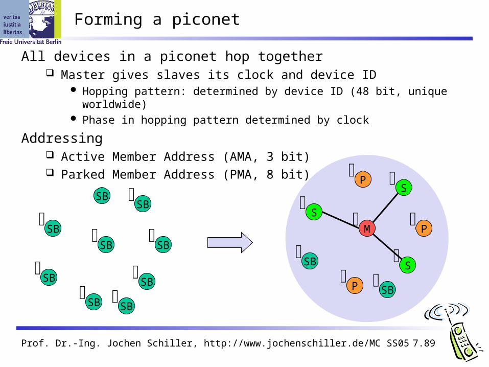
All devices in a piconet hop together Master gives slaves its clock and device ID
Hopping pattern: determined by device ID (48 bit, unique worldwide) Phase in hopping pattern determined by clock
Addressing Active Member Address (AMA, 3 bit) Parked Member Address (PMA, 8 bit)
SB
SB
SB
SB
SB
SB
SB
SB
SB
M
S
P
SB
S
S
P
P
SB
Prof. Dr.-Ing. Jochen Schiller, http://www.jochenschiller.de/ MC SS05 7.90
Scatternet
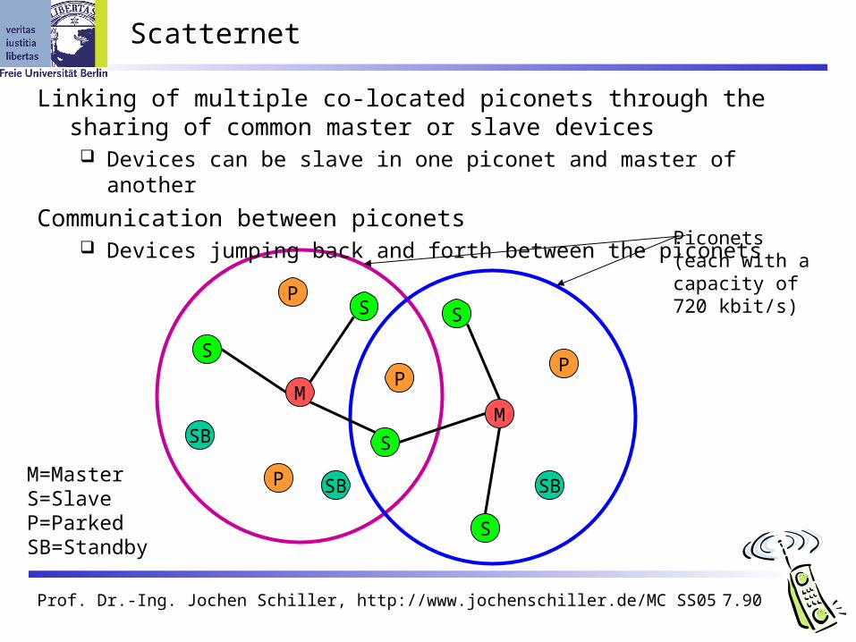
Linking of multiple co-located piconets through the sharing of common master or slave devices Devices can be slave in one piconet and master of another
Communication between piconets Devices jumping back and forth between the piconets
M=MasterS=SlaveP=ParkedSB=Standby
M
S
P
SB
S
S
P
P
SB
M
S
S
P
SB
Piconets(each with a capacity of 720 kbit/s)
Prof. Dr.-Ing. Jochen Schiller, http://www.jochenschiller.de/ MC SS05 7.91
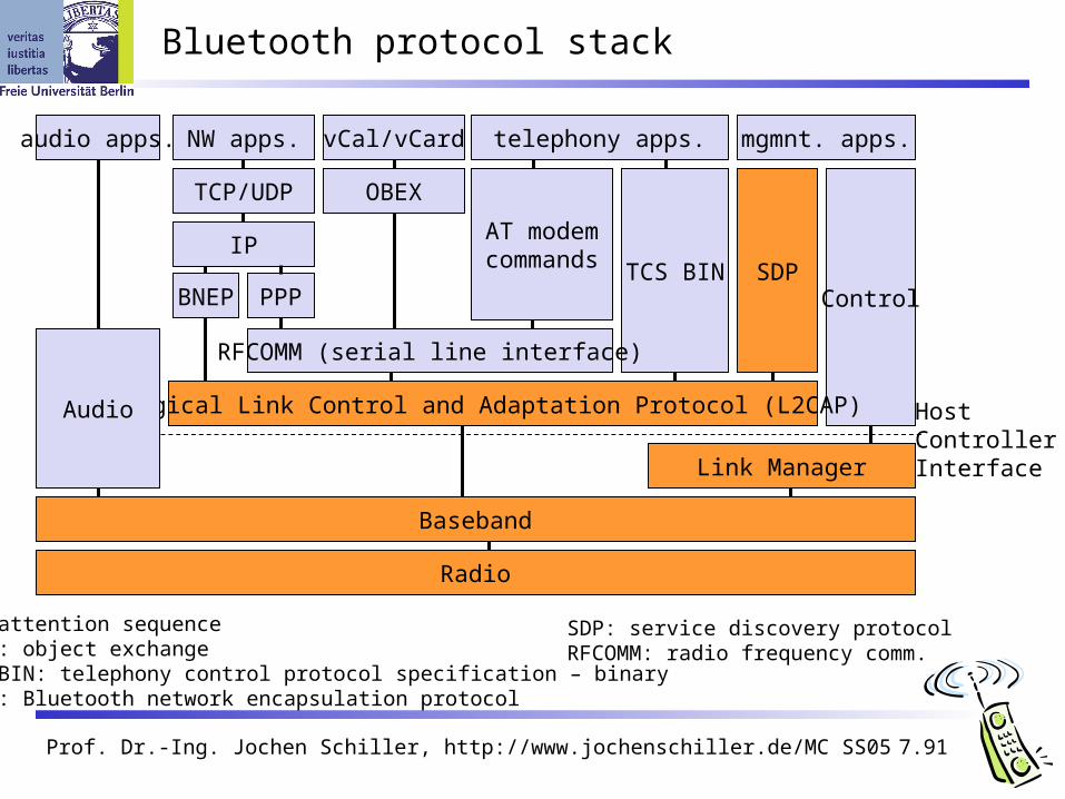
Bluetooth protocol stack
Radio
Baseband
Link Manager
Control
HostControllerInterface
Logical Link Control and Adaptation Protocol (L2CAP)Audio
TCS BIN SDP
OBEX
vCal/vCard
IP
NW apps.
TCP/UDP
BNEP
RFCOMM (serial line interface)
AT modemcommands
telephony apps.audio apps. mgmnt. apps.
AT: attention sequenceOBEX: object exchangeTCS BIN: telephony control protocol specification – binaryBNEP: Bluetooth network encapsulation protocol
SDP: service discovery protocolRFCOMM: radio frequency comm.
PPP

Prof. Dr.-Ing. Jochen Schiller, http://www.jochenschiller.de/ MC SS05 7.92
S
Frequency selection during data transmission
fk
625 µs
fk+1 fk+2 fk+3 fk+4
fk+3 fk+4fk
fk
fk+5
fk+5
fk+1 fk+6
fk+6
fk+6
MM M M
M
M M
M M
t
t
t
S S
S S
S

Prof. Dr.-Ing. Jochen Schiller, http://www.jochenschiller.de/ MC SS05 7.93
Baseband
Piconet/channel definition
Low-level packet definition Access code
Channel, device access, e.g., derived from master Packet header
1/3-FEC, active member address (broadcast + 7 slaves), link type, alternating bit ARQ/SEQ, checksum
access code packet header payload
68(72) 54 0-2745 bits
AM address type flow ARQN SEQN HEC
3 4 1 1 1 8 bits
preamble sync. (trailer)
4 64 (4)

Prof. Dr.-Ing. Jochen Schiller, http://www.jochenschiller.de/ MC SS05 7.94
SCO payload types
payload (30)
audio (30)
audio (10)
audio (10)
HV3
HV2
HV1
DV
FEC (20)
audio (20) FEC (10)
header (1) payload (0-9) 2/3 FEC CRC (2)
(bytes)

Prof. Dr.-Ing. Jochen Schiller, http://www.jochenschiller.de/ MC SS05 7.95
ACL Payload types
payload (0-343)
header (1/2) payload (0-339) CRC (2)
header (1) payload (0-17) 2/3 FEC
header (1) payload (0-27)
header (2) payload (0-121) 2/3 FEC
header (2) payload (0-183)
header (2) payload (0-224) 2/3 FEC
header (2) payload (0-339)DH5
DM5
DH3
DM3
DH1
DM1
header (1) payload (0-29)AUX1
CRC (2)
CRC (2)
CRC (2)
CRC (2)
CRC (2)
CRC (2)
(bytes)
Prof. Dr.-Ing. Jochen Schiller, http://www.jochenschiller.de/ MC SS05 7.96
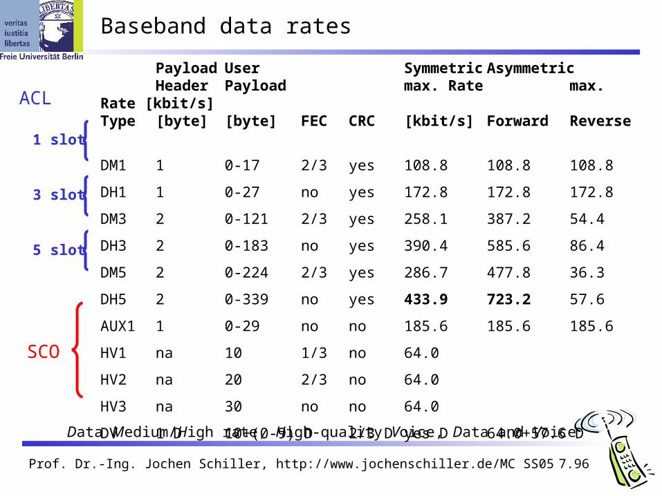
Baseband data rates
Payload User Symmetric AsymmetricHeader Payload max. Rate max. Rate [kbit/s]
Type [byte] [byte] FEC CRC [kbit/s] Forward Reverse
DM1 1 0-17 2/3 yes 108.8 108.8 108.8
DH1 1 0-27 no yes 172.8 172.8 172.8
DM3 2 0-121 2/3 yes 258.1 387.2 54.4
DH3 2 0-183 no yes 390.4 585.6 86.4
DM5 2 0-224 2/3 yes 286.7 477.8 36.3
DH5 2 0-339 no yes 433.9 723.2 57.6
AUX1 1 0-29 no no 185.6 185.6 185.6
HV1 na 10 1/3 no 64.0
HV2 na 20 2/3 no 64.0
HV3 na 30 no no 64.0
DV 1 D 10+(0-9) D 2/3 D yes D 64.0+57.6 D
ACL
1 slot
3 slot
5 slot
SCO
Data Medium/High rate, High-quality Voice, Data and Voice

Prof. Dr.-Ing. Jochen Schiller, http://www.jochenschiller.de/ MC SS05 7.97
Baseband link types
Polling-based TDD packet transmission 625µs slots, master polls slaves
SCO (Synchronous Connection Oriented) – Voice Periodic single slot packet assignment, 64 kbit/s full-duplex, point-to-point
ACL (Asynchronous ConnectionLess) – Data Variable packet size (1,3,5 slots), asymmetric bandwidth, point-to-multipoint
MASTER
SLAVE 1
SLAVE 2
f6f0
f1 f7
f12
f13 f19
f18
SCO SCO SCO SCOACL
f5 f21
f4 f20
ACLACLf8
f9
f17
f14
ACL
Prof. Dr.-Ing. Jochen Schiller, http://www.jochenschiller.de/ MC SS05 7.98
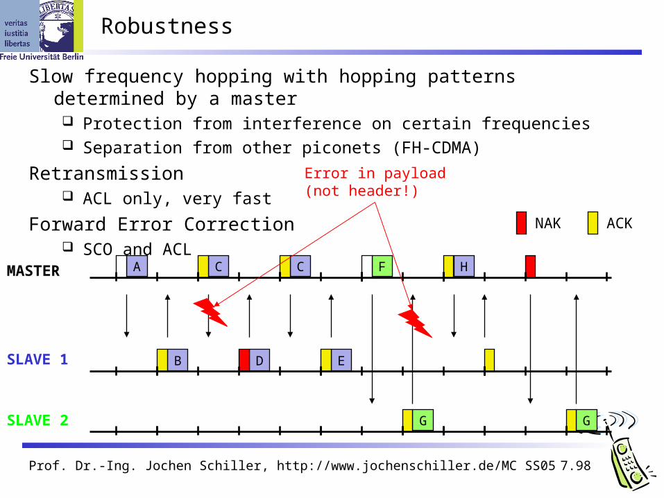
Robustness
Slow frequency hopping with hopping patterns determined by a master Protection from interference on certain frequencies Separation from other piconets (FH-CDMA)
Retransmission ACL only, very fast
Forward Error Correction SCO and ACL
MASTER
SLAVE 1
SLAVE 2
A C C HF
G G
B D E
NAK ACK
Error in payload(not header!)

Prof. Dr.-Ing. Jochen Schiller, http://www.jochenschiller.de/ MC SS05 7.99
Baseband states of a Bluetooth device
standby
inquiry page
connectedAMA
transmitAMA
parkPMA
holdAMA
sniffAMA
unconnected
connecting
active
low power
Standby: do nothingInquire: search for other devicesPage: connect to a specific deviceConnected: participate in a piconet
detach
Park: release AMA, get PMA Sniff: listen periodically, not each slotHold: stop ACL, SCO still possible, possibly
participate in another piconet

Prof. Dr.-Ing. Jochen Schiller, http://www.jochenschiller.de/ MC SS05 7.100
Example: Power consumption/CSR BlueCore2
Typical Average Current Consumption (1)VDD=1.8V Temperature = 20°CMode SCO connection HV3 (1s interval Sniff Mode) (Slave) 26.0 mASCO connection HV3 (1s interval Sniff Mode) (Master) 26.0 mASCO connection HV1 (Slave) 53.0 mASCO connection HV1 (Master) 53.0 mAACL data transfer 115.2kbps UART (Master) 15.5 mAACL data transfer 720kbps USB (Slave) 53.0 mAACL data transfer 720kbps USB (Master) 53.0 mAACL connection, Sniff Mode 40ms interval, 38.4kbps UART 4.0 mAACL connection, Sniff Mode 1.28s interval, 38.4kbps UART 0.5 mAParked Slave, 1.28s beacon interval, 38.4kbps UART 0.6 mAStandby Mode (Connected to host, no RF activity) 47.0 µADeep Sleep Mode(2) 20.0 µANotes:(1) Current consumption is the sum of both BC212015A and the flash.(2) Current consumption is for the BC212015A device only.(More: www.csr.com )
Prof. Dr.-Ing. Jochen Schiller, http://www.jochenschiller.de/ MC SS05 7.101
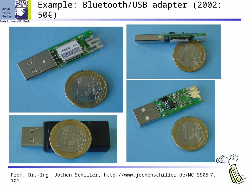
Example: Bluetooth/USB adapter (2002: 50€)
Prof. Dr.-Ing. Jochen Schiller, http://www.jochenschiller.de/ MC SS05 7.102
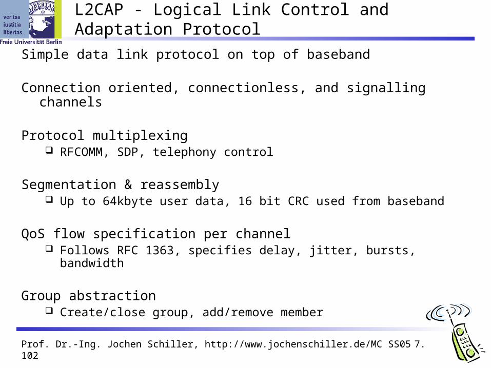
L2CAP - Logical Link Control and Adaptation Protocol
Simple data link protocol on top of baseband
Connection oriented, connectionless, and signalling channels
Protocol multiplexing RFCOMM, SDP, telephony control
Segmentation & reassembly Up to 64kbyte user data, 16 bit CRC used from baseband
QoS flow specification per channel Follows RFC 1363, specifies delay, jitter, bursts, bandwidth
Group abstraction Create/close group, add/remove member

Prof. Dr.-Ing. Jochen Schiller, http://www.jochenschiller.de/ MC SS05 7.103
L2CAP logical channels
baseband
L2CAP
baseband
L2CAP
baseband
L2CAP
Slave SlaveMaster
ACL
2 d 1 d d 1 1 d 21
signalling connectionless connection-oriented
d d d
Prof. Dr.-Ing. Jochen Schiller, http://www.jochenschiller.de/ MC SS05 7.104
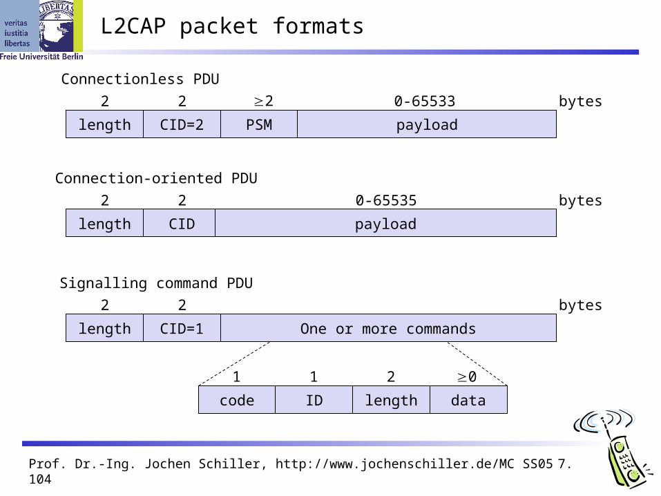
L2CAP packet formats
length
2 bytes
CID=2
2
PSM
2
payload
0-65533
length
2 bytes
CID
2
payload
0-65535
length
2 bytes
CID=1
2
One or more commands
Connectionless PDU
Connection-oriented PDU
Signalling command PDU
code ID length data
1 1 2 0

Prof. Dr.-Ing. Jochen Schiller, http://www.jochenschiller.de/ MC SS05 7.105
Security
E3
E2
link key (128 bit)
encryption key (128 bit)
payload key
Keystream generator
Data DataCipher data
Authentication key generation(possibly permanent storage)
Encryption key generation(temporary storage)
PIN (1-16 byte)User input (initialization)
Pairing
Authentication
Encryption
Ciphering
E3
E2
link key (128 bit)
encryption key (128 bit)
payload key
Keystream generator
PIN (1-16 byte)

Prof. Dr.-Ing. Jochen Schiller, http://www.jochenschiller.de/ MC SS05 7.106
SDP – Service Discovery Protocol
Inquiry/response protocol for discovering services Searching for and browsing services in radio proximity Adapted to the highly dynamic environment Can be complemented by others like SLP, Jini, Salutation, … Defines discovery only, not the usage of services Caching of discovered services Gradual discovery
Service record format Information about services provided by attributes Attributes are composed of an 16 bit ID (name) and a value values may be derived from 128 bit Universally Unique Identifiers (UUID)

Prof. Dr.-Ing. Jochen Schiller, http://www.jochenschiller.de/ MC SS05 7.107
Additional protocols to support legacy protocols/apps.
RFCOMM Emulation of a serial port (supports a large base of legacy applications) Allows multiple ports over a single physical channel
Telephony Control Protocol Specification (TCS) Call control (setup, release) Group management
OBEX Exchange of objects, IrDA replacement
WAP Interacting with applications on cellular phones
Prof. Dr.-Ing. Jochen Schiller, http://www.jochenschiller.de/ MC SS05 7.108
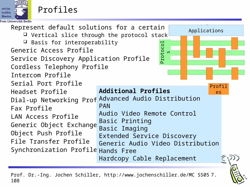
Profiles
Represent default solutions for a certain usage model Vertical slice through the protocol stack Basis for interoperability
Generic Access ProfileService Discovery Application ProfileCordless Telephony ProfileIntercom ProfileSerial Port ProfileHeadset ProfileDial-up Networking ProfileFax ProfileLAN Access ProfileGeneric Object Exchange ProfileObject Push ProfileFile Transfer ProfileSynchronization Profile
Additional ProfilesAdvanced Audio DistributionPANAudio Video Remote ControlBasic PrintingBasic ImagingExtended Service DiscoveryGeneric Audio Video DistributionHands FreeHardcopy Cable Replacement
Profiles
Pro
toco
ls
Applications

Prof. Dr.-Ing. Jochen Schiller, http://www.jochenschiller.de/ MC SS05 7.109
WPAN: IEEE 802.15-1 – Bluetooth
Data rate Synchronous, connection-oriented:
64 kbit/s Asynchronous, connectionless
433.9 kbit/s symmetric 723.2 / 57.6 kbit/s asymmetric
Transmission range POS (Personal Operating Space)
up to 10 m with special transceivers up to 100
m
Frequency Free 2.4 GHz ISM-band
Security Challenge/response (SAFER+),
hopping sequence
Availability Integrated into many products,
several vendors
Connection set-up time Depends on power-mode Max. 2.56s, avg. 0.64s
Quality of Service Guarantees, ARQ/FEC
Manageability Public/private keys needed, key
management not specified, simple system integration
Special Advantages/Disadvantages Advantage: already integrated into
several products, available worldwide, free ISM-band, several vendors, simple system, simple ad-hoc networking, peer to peer, scatternets
Disadvantage: interference on ISM-band, limited range, max. 8 devices/network&master, high set-up latency

Prof. Dr.-Ing. Jochen Schiller, http://www.jochenschiller.de/ MC SS05 7.110
WPAN: IEEE 802.15 – future developments 1
802.15-2: Coexistance Coexistence of Wireless Personal Area Networks (802.15) and Wireless
Local Area Networks (802.11), quantify the mutual interference
802.15-3: High-Rate Standard for high-rate (20Mbit/s or greater) WPANs, while still
low-power/low-cost Data Rates: 11, 22, 33, 44, 55 Mbit/s Quality of Service isochronous protocol Ad hoc peer-to-peer networking Security Low power consumption Low cost Designed to meet the demanding requirements of portable consumer
imaging and multimedia applications

Prof. Dr.-Ing. Jochen Schiller, http://www.jochenschiller.de/ MC SS05 7.111
WPAN: IEEE 802.15 – future developments 2
Several working groups extend the 802.15.3 standard
802.15.3a: Alternative PHY with higher data rate as extension to 802.15.3 Applications: multimedia, picture transmission
802.15.3b: Enhanced interoperability of MAC Correction of errors and ambiguities in the standard
802.15.3c: Alternative PHY at 57-64 GHz Goal: data rates above 2 Gbit/s
Not all these working groups really create a standard, not all standards will be found in products later …
Prof. Dr.-Ing. Jochen Schiller, http://www.jochenschiller.de/ MC SS05 7.112
WPAN: IEEE 802.15 – future developments 3
802.15-4: Low-Rate, Very Low-Power Low data rate solution with multi-month to multi-year battery life and very
low complexity Potential applications are sensors, interactive toys, smart badges, remote
controls, and home automation Data rates of 20-250 kbit/s, latency down to 15 ms Master-Slave or Peer-to-Peer operation Up to 254 devices or 64516 simpler nodes Support for critical latency devices, such as joysticks CSMA/CA channel access (data centric), slotted (beacon) or unslotted Automatic network establishment by the PAN coordinator Dynamic device addressing, flexible addressing format Fully handshaked protocol for transfer reliability Power management to ensure low power consumption 16 channels in the 2.4 GHz ISM band, 10 channels in the 915 MHz US ISM
band and one channel in the European 868 MHz band
Basis of the ZigBee technology – www.zigbee.org

Prof. Dr.-Ing. Jochen Schiller, http://www.jochenschiller.de/ MC SS05 7.113
ZigBee
Relation to 802.15.4 similar to Bluetooth / 802.15.1
Pushed by Chipcon, ember, freescale (Motorola), Honeywell, Mitsubishi, Motorola, Philips, Samsung
More than 150 members Promoter (40000$/Jahr), Participant (9500$/Jahr), Adopter (3500$/Jahr)
No free access to the specifications (only promoters and participants)
ZigBee platforms comprise IEEE 802.15.4 for layers 1 and 2 ZigBee protocol stack up to the applications

Prof. Dr.-Ing. Jochen Schiller, http://www.jochenschiller.de/ MC SS05 7.114
WPAN: IEEE 802.15 – future developments 4
Several working groups extend the 802.15.4 standard
802.15.4a: Alternative PHY with lower data rate as extension to 802.15.4 Properties: precise localization (< 1m precision), extremely low power consumption,
longer range Two PHY alternatives
UWB (Ultra Wideband): ultra short pulses, communication and localization CSS (Chirp Spread Spectrum): communication only
802.15.4b: Extensions, corrections, and clarifications regarding 802.15.4 Usage of new bands, more flexible security mechanisms
802.15.5: Mesh Networking Partial meshes, full meshes Range extension, more robustness, longer battery live
Not all these working groups really create a standard, not all standards will be found in products later …

Prof. Dr.-Ing. Jochen Schiller, http://www.jochenschiller.de/ MC SS05 7.115
Some more IEEE standards for mobile communications
IEEE 802.16: Broadband Wireless Access / WirelessMAN / WiMax Wireless distribution system, e.g., for the last mile, alternative to DSL 75 Mbit/s up to 50 km LOS, up to 10 km NLOS; 2-66 GHz band Initial standards without roaming or mobility support 802.16e adds mobility support, allows for roaming at 150 km/h
Unclear relation to 802.20, 802.16 started as fixed system…
IEEE 802.20: Mobile Broadband Wireless Access (MBWA) Licensed bands < 3.5 GHz, optimized for IP traffic Peak rate > 1 Mbit/s per user Different mobility classes up to 250 km/h and ranges up to 15 km
IEEE 802.21: Media Independent Handover Interoperability Standardize handover between different 802.x and/or non 802 networks
IEEE 802.22: Wireless Regional Area Networks (WRAN) Radio-based PHY/MAC for use by license-exempt devices on a non-
interfering basis in spectrum that is allocated to the TV Broadcast Service

Prof. Dr.-Ing. Jochen Schiller, http://www.jochenschiller.de/ MC SS05 7.116
WLAN: Home RF – yet another standard, no success
Data rate 0.8, 1.6, 5, 10 Mbit/s
Transmission range 300m outdoor, 30m indoor
Frequency 2.4 GHz ISM
Security Strong encryption, no open access
Cost Adapter 130€, base station 230€
Availability Several products from different
vendors, no more support
Connection set-up time 10 ms bounded latency
Quality of Service Up to 8 streams A/V, up to 8 voice
streams, priorities, best-effort
Manageability Like DECT & 802-LANs
Special Advantages/Disadvantages Advantage: extended QoS support,
host/client and peer/peer, power saving, security
Disadvantage: future uncertain due to DECT-only devices plus 802.11a/b for data

Prof. Dr.-Ing. Jochen Schiller, http://www.jochenschiller.de/ MC SS05 7.117
RF Controllers – ISM bands
Data rate Typ. up to 115 kbit/s (serial
interface)
Transmission range 5-100 m, depending on power (typ.
10-500 mW)
Frequency Typ. 27 (EU, US), 315 (US), 418
(EU), 426 (Japan), 433 (EU), 868 (EU), 915 (US) MHz (depending on regulations)
Security Some products with added
processors
Cost Cheap: 10€-50€
Availability Many products, many vendors
Connection set-up time N/A
Quality of Service none
Manageability Very simple, same as serial
interface
Special Advantages/Disadvantages Advantage: very low cost, large
experience, high volume available Disadvantage: no QoS, crowded
ISM bands (particularly 27 and 433 MHz), typ. no Medium Access Control, 418 MHz experiences interference with TETRA
Prof. Dr.-Ing. Jochen Schiller, http://www.jochenschiller.de/ MC SS05 7.118
RFID – Radio Frequency Identification (1)
Data rate Transmission of ID only (e.g., 48 bit,
64kbit, 1 Mbit) 9.6 – 115 kbit/s
Transmission range Passive: up to 3 m Active: up to 30-100 m Simultaneous detection of up to, e.g.,
256 tags, scanning of, e.g., 40 tags/s
Frequency 125 kHz, 13.56 MHz, 433 MHz, 2.4 GHz,
5.8 GHz and many others
Security Application dependent, typ. no crypt. on
RFID device
Cost Very cheap tags, down to 1€ (passive)
Availability Many products, many vendors
Connection set-up time Depends on product/medium access
scheme (typ. 2 ms per device)
Quality of Service none
Manageability Very simple, same as serial interface
Special Advantages/Disadvantages Advantage: extremely low cost, large
experience, high volume available, no power for passive RFIDs needed, large variety of products, relative speeds up to 300 km/h, broad temp. range
Disadvantage: no QoS, simple denial of service, crowded ISM bands, typ. one-way (activation/ transmission of ID)
Prof. Dr.-Ing. Jochen Schiller, http://www.jochenschiller.de/ MC SS05 7.119
RFID – Radio Frequency Identification (2)
Function Standard: In response to a radio interrogation signal from a reader (base
station) the RFID tags transmit their ID Enhanced: additionally data can be sent to the tags, different media access
schemes (collision avoidance)
Features No line-of sight required (compared to, e.g., laser scanners) RFID tags withstand difficult environmental conditions (sunlight, cold, frost,
dirt etc.) Products available with read/write memory, smart-card capabilities
Categories Passive RFID: operating power comes from the reader over the air which is
feasible up to distances of 3 m, low price (1€) Active RFID: battery powered, distances up to 100 m
Prof. Dr.-Ing. Jochen Schiller, http://www.jochenschiller.de/ MC SS05 7.120
RFID – Radio Frequency Identification (3)
Applications Total asset visibility: tracking of goods during manufacturing, localization of
pallets, goods etc. Loyalty cards: customers use RFID tags for payment at, e.g., gas stations,
collection of buying patterns Automated toll collection: RFIDs mounted in windshields allow commuters
to drive through toll plazas without stopping Others: access control, animal identification, tracking of hazardous
material, inventory control, warehouse management, ...
Local Positioning Systems GPS useless indoors or underground, problematic in cities with high
buildings RFID tags transmit signals, receivers estimate the tag location by
measuring the signal‘s time of flight

Prof. Dr.-Ing. Jochen Schiller, http://www.jochenschiller.de/ MC SS05 7.121
RFID – Radio Frequency Identification (4)
Security Denial-of-Service attacks are always possible
Interference of the wireless transmission, shielding of transceivers IDs via manufacturing or one time programming Key exchange via, e.g., RSA possible, encryption via, e.g., AES
Future Trends RTLS: Real-Time Locating System – big efforts to make total asset visibility
come true Integration of RFID technology into the manufacturing, distribution and
logistics chain Creation of „electronic manifests“ at item or package level (embedded
inexpensive passive RFID tags) 3D tracking of children, patients

Prof. Dr.-Ing. Jochen Schiller, http://www.jochenschiller.de/ MC SS05 7.122
RFID – Radio Frequency Identification (5)
Devices and Companies AXCESS Inc., www.axcessinc.com Checkpoint Systems Group, www.checkpointsystems.com GEMPLUS, www.gemplus.com/app/smart_tracking Intermec/Intellitag, www.intermec.com I-Ray Technologies, www.i-ray.com RF Code, www.rfcode.com Texas Instruments, www.ti-rfid.com/id WhereNet, www.wherenet.com Wireless Mountain, www.wirelessmountain.com XCI, www.xci-inc.com
Only a very small selection…
Prof. Dr.-Ing. Jochen Schiller, http://www.jochenschiller.de/ MC SS05 7.123
RFID – Radio Frequency Identification (6)
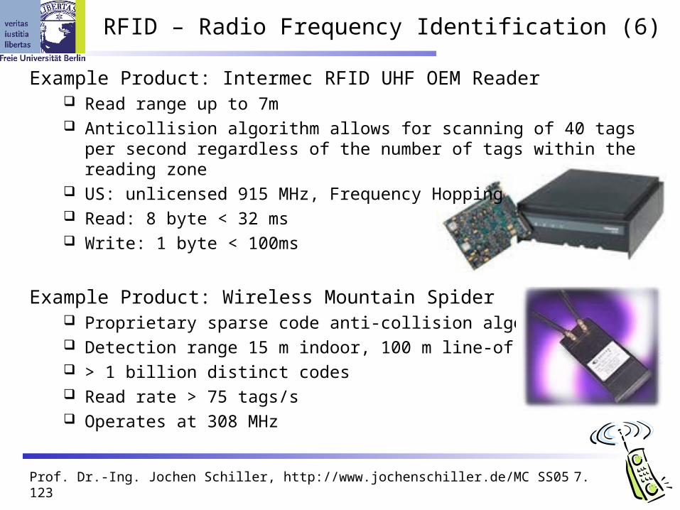
Example Product: Intermec RFID UHF OEM Reader Read range up to 7m Anticollision algorithm allows for scanning of 40 tags per second regardless
of the number of tags within the reading zone US: unlicensed 915 MHz, Frequency Hopping Read: 8 byte < 32 ms Write: 1 byte < 100ms
Example Product: Wireless Mountain Spider Proprietary sparse code anti-collision algorithm Detection range 15 m indoor, 100 m line-of-sight > 1 billion distinct codes Read rate > 75 tags/s Operates at 308 MHz

Prof. Dr.-Ing. Jochen Schiller, http://www.jochenschiller.de/ MC SS05 7.124
RFID – Radio Frequency Identification (7)
Relevant Standards American National Standards Institute
ANSI, www.ansi.org, www.aimglobal.org/standards/rfidstds/ANSIT6.html Automatic Identification and Data Capture Techniques
JTC 1/SC 31, www.uc-council.com/sc31/home.htm, www.aimglobal.org/standards/rfidstds/sc31.htm
European Radiocommunications Office ERO, www.ero.dk, www.aimglobal.org/standards/rfidstds/ERO.htm
European Telecommunications Standards Institute ETSI, www.etsi.org, www.aimglobal.org/standards/rfidstds/ETSI.htm
Identification Cards and related devices JTC 1/SC 17, www.sc17.com, www.aimglobal.org/standards/rfidstds/sc17.htm,
Identification and communication ISO TC 104 / SC 4, www.autoid.org/tc104_sc4_wg2.htm,
www.aimglobal.org/standards/rfidstds/TC104.htm Road Transport and Traffic Telematics
CEN TC 278, www.nni.nl, www.aimglobal.org/standards/rfidstds/CENTC278.htm Transport Information and Control Systems
ISO/TC204, www.sae.org/technicalcommittees/gits.htm, www.aimglobal.org/standards/rfidstds/ISOTC204.htm

Prof. Dr.-Ing. Jochen Schiller, http://www.jochenschiller.de/ MC SS05 7.125
RFID – Radio Frequency Identification (8)
ISO Standards ISO 15418
MH10.8.2 Data Identifiers EAN.UCC Application Identifiers
ISO 15434 - Syntax for High Capacity ADC Media ISO 15962 - Transfer Syntax ISO 18000
Part 2, 125-135 kHz Part 3, 13.56 MHz Part 4, 2.45 GHz Part 5, 5.8 GHz Part 6, UHF (860-930 MHz, 433 MHz)
ISO 18047 - RFID Device Conformance Test Methods ISO 18046 - RF Tag and Interrogator Performance Test Methods

Prof. Dr.-Ing. Jochen Schiller, http://www.jochenschiller.de/ MC SS05 7.126
ISM band interference
Many sources of interference Microwave ovens, microwave lightning 802.11, 802.11b, 802.11g, 802.15, Home RF Even analog TV transmission, surveillance Unlicensed metropolitan area networks …
Levels of interference Physical layer: interference acts like noise
Spread spectrum tries to minimize this FEC/interleaving tries to correct
MAC layer: algorithms not harmonized E.g., Bluetooth might confuse 802.11
OLD
© Fusion Lighting, Inc.
NEW

Prof. Dr.-Ing. Jochen Schiller, http://www.jochenschiller.de/ MC SS05 7.127
Bluetooth may act like a rogue member of the 802.11 network Does not know anything about gaps, inter frame spacing etc.
IEEE 802.15-2 discusses these problems Proposal: Adaptive Frequency Hopping
a non-collaborative Coexistence Mechanism
Real effects? Many different opinions, publications, tests, formulae, … Results from complete breakdown to almost no effect Bluetooth (FHSS) seems more robust than 802.11b (DSSS)
802.11 vs.(?) 802.15/Bluetooth
t
f [MHz]
2402
2480 802.11b 3 channels(separated by installation)
AC
K
DIF
S
DIF
S
SIF
S
1000 byte
SIF
S
DIF
S
500 byteA
CK
DIF
S
500 byte
SIF
SA
CK
DIF
S
500 byte
DIF
S 100byte S
IFS
AC
K
DIF
S 100byte S
IFS
AC
K
DIF
S 100byte S
IFS
AC
K
DIF
S 100byte S
IFS
AC
K
DIF
S 100byte S
IFS
AC
K
802.15.1 79 channels(separated by hopping pattern)