products redesign development and management methodology ... · products redesign development and...
TRANSCRIPT

Products redesign development and management methodology in engineering- a
case study Sanket Sharad Chaudhari
Department of Mechanical Engineering Sardar Patel College of Engineering
Mumbai, India [email protected]
Abstract
The purpose of writing this paper is to understand design methodology and management in engineering. The paper objects exploring how effective and more reliable product may be designed. Designing an optimized new product is an important challenge in itself and is of significant practical and research interest. The paper summarizes and expands upon product design concepts as they appear in development processes and their effect on management. Keywords - Conceptual design, product design, design for manufacturing and assembly, human factor engineering, product development
1) Introduction In this paper a detail study of design in an Indian company is done. Design engineering is set of the principles of designing of the product for maker to established best suitable combination of it so that the user gets satisfied. Engineers are expected to understand change in requirement of customers and to develop new principles for satisfaction of customers in machine redesign. A complete study of all design stages are explained in this paper. The case presented here is redesigning a machine used for making milk pouch. Case study is carried out in a company called ‘Samarpan Fabricators PVT LTD’. The new machine development can be studied by following stages shows in table 1 (1)
Table I Design stages sequence with concept detail in respective domain
Stage no.
Stage Name
Concept Used
Conceptual design
1 Defining problem
QFD FMEA Fish bone diagram PDS NPD
2 Concept generation
Morphological chart
3 Evaluation of concept
Pugh concept selection decision
Embodiment design
4 Product architecture
Arrangement of the physical elements to carry out function
5 Configuration design
Modeling and sizing of the parts
6 Parametric design
DFM,DFA, DFE
7 Detail design Detail drawing and specification
(2)
Sanket Sharad Chaudhari / International Journal of Advances in Engineering, Science and Technology (IJAEST)
ISSN : 2249-913X Vol. 3 No. 1 Feb-Apr 2013 7

2) Design Stages A. Stage 1: Define Problem
There have been estimations made which tell us that approximately 90% of all good technical products are not a success in the marketplace (3). Note that a product itself can be technically advanced according to function, materials selection, etc., but for many reasons the product is a market failure (4). Hence defining problem is the most valuable and critical task.
i) Failure mode and effect analysis Failure mode effect analysis is a team-based methodology for identifying potential problems with new or exisitng design(5).It is an analysis tool for evaluating reliability by examining expected failure modes to find the effects of failure on equipment and system. The FMEA is shown in table no. 2
ii) Quality Function Deployment Qality function deployment is a planning and problem solving tool that is finding growing acceptance for translating customer requirements into the engineering characteristic of a product(6). QFD is shown below
iii) Product design specification
The product design specification (PDS) is the basic control and reference document for the design and manufacturing of product(7). The PDS is a document contains all of the fact related to the outcome of the product development. Product design specification for the machine is shown in table no 3
Table II failure mode effect analysis
Process description
Potential Failure mode
Potential cause of failure
Potential effect of failure
Current control
For Old Machine Recommendations
For New Machine
Occ
urr
ence
Sev
erit
y
Det
ecti
on
RP
N
Occ
urr
ence
Sev
erit
y
Det
ecti
on
RP
N
Packing of pouch
Short pouch 1. Film jammed in back of machine 2. Bad Teflon tape on vertical seal bar.
Short pouch Short pouch
100% Visual 100% Visual
2 1
1 1
1 1
2 1
Place additional support roller Replace Teflon tape.
0 1
- 1
- 1
- 1
Transmission Disassembly of gear element.
1. Internal misalignment in gear box. 2. Noisy worn out bearing
Gear box failure Gear box failure
Machine stops Machine stops
2 1
9 9
2 2
36 18
Use helical gear box with self-aligning ball bearings
1 1
9 9
1 1
9 9
Liquid filling Injection valves leaks
1. Damaged Valve seats at bottom of fill tube. 2.Foreign body wedged in end of injection tube like rubber
Improper fill of milk Improper fill of milk
100% Visual 100% Visual
2 2
4 4
3 2
24 16
Introduce Separate Supports Keep position of injector inside the film tube.
1 1
4 4
1 1
4 4
Sealing Element overheat (smoke) during operation
1. Heat setting potentiometer dial set too high. 2. Improperly mounted sealing element.
Teflon burns Teflon burns
Temp. sensor Temp. sensor
1 2
3 3
2 2
6 12
Lock the potentiometer rating. Provide extra attachment.
1 1
3 3
1 1
3 3
Sanket Sharad Chaudhari / International Journal of Advances in Engineering, Science and Technology (IJAEST)
ISSN : 2249-913X Vol. 3 No. 1 Feb-Apr 2013 8

Figure 1 Quality function deployment
Sanket Sharad Chaudhari / International Journal of Advances in Engineering, Science and Technology (IJAEST)
ISSN : 2249-913X Vol. 3 No. 1 Feb-Apr 2013 9

Table III Product design specification
SR. NO PARAMETER EXPLANATION
1 Product title Sampre-6 2 Purpose To facilitate better packing of milk 3 New or special feature 1. High performance
2. Less power 3. Improved ergonomics
4 Competition All seal packing machine companies. 5 Intended market Sell to direct dairies. Secondary market will be oil, shampoo, sauce
companies. 6 Need for product Feedback from the customers has shown more interest in new features. Less
power consuming and high performance machines are strongly expected by customers.
7 Relationship with existing product line Very close and strong relationship with old customers. 8 Market demand 4,36,000 litres of milk packets everyday 9 Functional performance 1. Able to pack a 1 litre milk pack within 0.68 second
2. Allows easy handling 3. Able to consume power even less than 3.5 KW/ hr 4. Follows Noise pollution standards of ISO 14001 EMS
10 Physical requirement Materials: Stainless steel, Aluminium, Plastic, rubber, glass. Size : 1600 765 3000 Transparent front door
11 Legal requirement 1. Only Stainless steel and Aluminium should be used. 2. The machine should satisfy Standards of weight and measures
(Enforcement) Act, 1985 (INDIA) 3. No toxic material should be associated with milk packing and
storage. 4. The machine should satisfy ISO 14001 EMS standards
Failures and problems observed in old machines are – 1. Machine consumes high power 2. Film jamming take places 3. It has bulky gear box 4. Noise pollution is uncomfortable 5. Packing speed is low
Above problems are itself tasks for the new project. These problems should be eliminated for new machine. i) New product development
New product were seen to be the result of a proactive research and development (R&D) effort, with the marketplace viewed as a mere receptacle for the fruits of the development process (8). Good practice has been characterized by team-based organization and product champions (9) (10). Check figure no 1 As organizational success often depends on the timely and consistent introduction of new products, it is unsurprising that the new product development (NPD) literature contains many prescriptions for high-performance product development (11; 12) (13) (14-17) Few of the points are mentioned here.
1. Top Management Support for Innovation Principle - Assigning the best managers to the role of developing new products Action taken by company - Previous research reports that the project manager is the pivotal figure in the development process (11)and that project leadership critically affects both the process performance and the effectiveness of the product (11).
Sanket Sharad Chaudhari / International Journal of Advances in Engineering, Science and Technology (IJAEST)
ISSN : 2249-913X Vol. 3 No. 1 Feb-Apr 2013 10
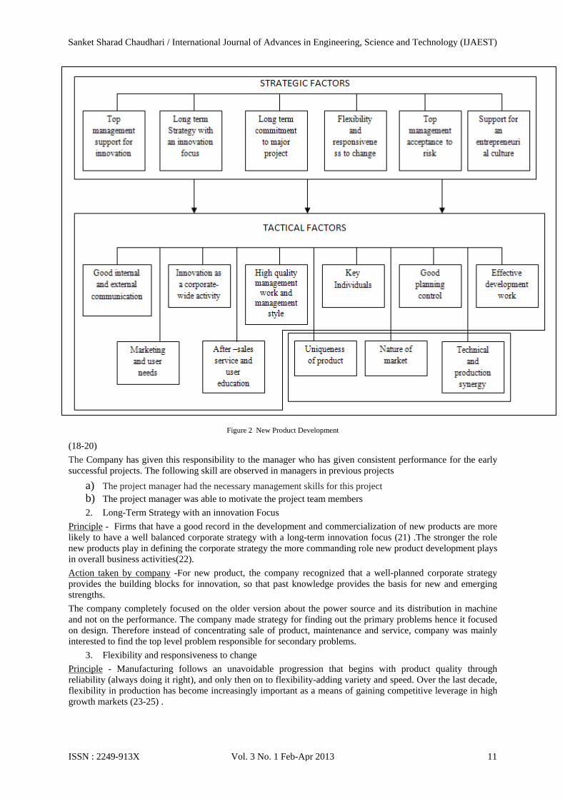
Figure 2 New Product Development
(18-20) The Company has given this responsibility to the manager who has given consistent performance for the early successful projects. The following skill are observed in managers in previous projects
a) The project manager had the necessary management skills for this project b) The project manager was able to motivate the project team members 2. Long-Term Strategy with an innovation Focus
Principle - Firms that have a good record in the development and commercialization of new products are more likely to have a well balanced corporate strategy with a long-term innovation focus (21) .The stronger the role new products play in defining the corporate strategy the more commanding role new product development plays in overall business activities(22). Action taken by company -For new product, the company recognized that a well-planned corporate strategy provides the building blocks for innovation, so that past knowledge provides the basis for new and emerging strengths. The company completely focused on the older version about the power source and its distribution in machine and not on the performance. The company made strategy for finding out the primary problems hence it focused on design. Therefore instead of concentrating sale of product, maintenance and service, company was mainly interested to find the top level problem responsible for secondary problems.
3. Flexibility and responsiveness to change Principle - Manufacturing follows an unavoidable progression that begins with product quality through reliability (always doing it right), and only then on to flexibility-adding variety and speed. Over the last decade, flexibility in production has become increasingly important as a means of gaining competitive leverage in high growth markets (23-25) .
Sanket Sharad Chaudhari / International Journal of Advances in Engineering, Science and Technology (IJAEST)
ISSN : 2249-913X Vol. 3 No. 1 Feb-Apr 2013 11

Action taken by company- The Company works with only projects, hence according to customers’ requirement the projects are made and products are manufactured. For this reason company has already accepted flexibility concept and for model SAMPRE-6 company went through the same concept.
B. Stage 2: Concept generation
Morphological chart The morphological chart arranges the functions and sub functions in logical order, and for each sub function lists the possible hows (26). The morphological word means the study of shape or form; so morphological analysis is a way of creating new forms, i.e., design concept (27)check table no. 4
Table IV Morphological Chart
Sr. no
Sub function
s
Concepts
1 2 3
1 Reduce dial
setting
By hand By Jaw pressure
By unwrapping
sealing 2 Film
jamming Decrease
length between
roller
Provide extra roller
Place film spool at the
top
3 Placement of film
roller
By hand By hanger
4 Power Pneumatic within built compressor
Electric motor
5 Indicator lights
Bulb LED
6 Gear Helical Spur
7 Film feed
Nip rollers Threads on film
8 Switch control panel
Separate sections with in machine
Wired Remote
controller
9 Quantity measuri
ng
By Discharge
By weight
C. Stage 3: Evaluation of concept
Pugh’s Concept selection method - individual methods are developed for assessing novelty and usefulness of products, and then combine these into a method for assessing creativity of product (28). A particularly good method for deciding on the most prominent design concept at all the concept stage is the Pugh’s Concept selection method (29-31). The method is conducted within the concept and design phase during product development (32). The method compares each concept relative to reference or datum concept and for each criterion determines whether the concept in question is better than, poorer than, or about same as reference concept (33). Company work: Shown in table 5 Pugh concept selection is not used by the company because it does not evaluate the concept about its achievement.
Table V Pugh concept selection method
Criterion Concept 1 Concept 2 Concept 3 Min I/P and max O/P machine
Gear box + S - D A T U M
Power Source S + Film Jamming S + - Switch control panel S - Overload control + S S ∑+ 2 2 0 ∑- 0 1 2 ∑S 3 2 1
Sanket Sharad Chaudhari / International Journal of Advances in Engineering, Science and Technology (IJAEST)
ISSN : 2249-913X Vol. 3 No. 1 Feb-Apr 2013 12

D Stage 4: Product architecture
Product architecture is the arrangement of the physical elements of a product to carry put its required function. The product architecture begins to emerge in the conceptual design phase with such things as diagrams of functions, rough sketches of the concepts, and perhaps a proof-of-concept model (34) . Ulrich and Eppinger (35) propose a four step for establishing the product architecture.
1. Create a schematic diagram of the product 2. Cluster the element of the schematic 3. Create a rough geometric layout
Product architecture stepwise progress is shown in Figure 2, 3, 4.
Figure 3 Schematic diagram of the product Figure 4 Clustered element of the schematic
Sanket Sharad Chaudhari / International Journal of Advances in Engineering, Science and Technology (IJAEST)
ISSN : 2249-913X Vol. 3 No. 1 Feb-Apr 2013 13
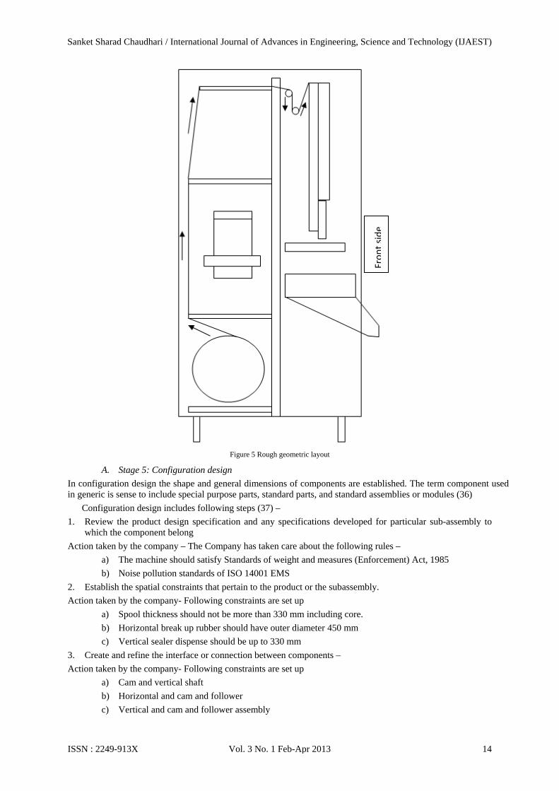
Figure 5 Rough geometric layout
A. Stage 5: Configuration design
In configuration design the shape and general dimensions of components are established. The term component used in generic is sense to include special purpose parts, standard parts, and standard assemblies or modules (36) Configuration design includes following steps (37) – 1. Review the product design specification and any specifications developed for particular sub-assembly to
which the component belong Action taken by the company – The Company has taken care about the following rules –
a) The machine should satisfy Standards of weight and measures (Enforcement) Act, 1985 b) Noise pollution standards of ISO 14001 EMS
2. Establish the spatial constraints that pertain to the product or the subassembly. Action taken by the company- Following constraints are set up
a) Spool thickness should not be more than 330 mm including core. b) Horizontal break up rubber should have outer diameter 450 mm c) Vertical sealer dispense should be up to 330 mm
3. Create and refine the interface or connection between components – Action taken by the company- Following constraints are set up
a) Cam and vertical shaft b) Horizontal and cam and follower c) Vertical and cam and follower assembly
Fron
tsid
e
Sanket Sharad Chaudhari / International Journal of Advances in Engineering, Science and Technology (IJAEST)
ISSN : 2249-913X Vol. 3 No. 1 Feb-Apr 2013 14

d) PLC and actuator interface are established 4. Before spending much time on the design, answer the following
a) Can the part be eliminated or combined with another part? Ans. - Yes, most of parts are eliminated and common parts are used.
b) Can a standard part or module be used? Ans. – Yes, Electric motor and shaft of standard specifications are used.
B. Stage 6: Parametric design
Design for Manufacturing and Design for Assembly Design for Manufacturing (DFM) and design for assembly (DFA) are the integration of product design and process planning into one common activity. The goal is to design a product that is easily and economically manufactured. The basis of design for manufacture and assembly is a systematic procedure for analyzing product designs based on the application of quantifiable data(38).
I. Reduction of the total number of parts Principle-A part is good candidate for elimination if there is no need for relative motion, no need for subsequent adjustment between parts, and no need for materials to be different (39). Hence procurement and manufacturing cost decreases. At the same time as no. of parts decreases system possesses less inertia hence less power is required to run the system and friction also decreases. Action taken by company– the company removed the air pipes and the corresponding kinematic chain is removed. In new machine power is transmitted with the help of only one shaft i.e. one-piece structures and movements of valves is done by cam and follower. It is shown in figure 5
Figure 6 Cam and follower
II. Use of standard components – Principle – Costs are minimized and quality is enhanced when standard commercially available components are used in design (39). The high availability of these components reduces product lead times. Also, their reliability factors are well ascertained Action taken by company- The Company selected motor of following standard specifications. Power: 3 phase 415 volts motor with 1000 rpm (960 rpm) Load no each phase: R Phase – 1.2 KVA Y Phase – 5 KVA B Phase – 5 KVA
Follower
Cam
Sanket Sharad Chaudhari / International Journal of Advances in Engineering, Science and Technology (IJAEST)
ISSN : 2249-913X Vol. 3 No. 1 Feb-Apr 2013 15
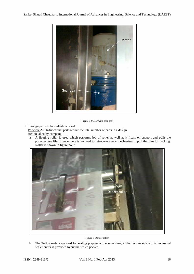
Figure 7 Motor with gear box
III.Design parts to be multi-functional. Principle-Multi-functional parts reduce the total number of parts in a design. Action taken by company – a. A floating roller is used which performs job of roller as well as it floats on support and pulls the
polyethylene film. Hence there is no need to introduce a new mechanism to pull the film for packing. Roller is shown in figure no. 7
Figure 8 Dancer roller
b. The Teflon sealers are used for sealing purpose at the same time, at the bottom side of this horizontal sealer cutter is provided to cut the sealed packet.
Gear box
Motor
Dancer roller
Motor
Gear box
Sanket Sharad Chaudhari / International Journal of Advances in Engineering, Science and Technology (IJAEST)
ISSN : 2249-913X Vol. 3 No. 1 Feb-Apr 2013 16
IV. Minimize assembly directions (40) Principle - All parts should be assembled from one direction. This reduces the complexity during assembly.
Action taken by company– The Company had chosen the direction to assemble the part from top to bottom in a vertical direction parallel to gravity. In this way, the effects of gravity help the assembly process, contrary to having to compensate for its effect when their directions are chosen
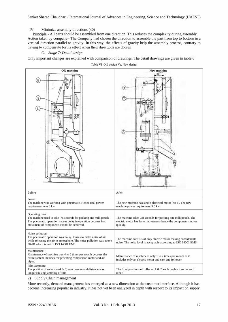
C. Stage 7: Detail design
Only important changes are explained with comparison of drawings. The detail drawings are given in table 6 Table VI Old design Vs. New design
Old machine
New machine
Before After
Power: The machine was working with pneumatic. Hence total power requirement was 8 kw.
The new machine has single electrical motor (no 3). The new machine power requirement 3.5 kw.
Operating time: The machine used to take .75 seconds for packing one milk pouch. The pneumatic operation causes delay in operation because fast movement of components cannot be achieved.
The machine takes .68 seconds for packing one milk pouch. The electric motor has faster movements hence the components moves quickly.
Noise pollution: The pneumatic operation was noisy. It uses to make noise of air while releasing the air to atmosphere. The noise pollution was above 80 dB which is not fit ISO 14001 EMS.
The machine consists of only electric motor making considerable noise. The noise level is acceptable according to ISO 14001 EMS.
Maintenance: Maintenance of machine was 4 to 5 times per month because the entire system includes reciprocating compressor, motor and air pipes.
Maintenance of machine is only 1 to 2 times per month as it includes only an electric motor and cam and follower.
Film Jamming: The position of roller (no.4 & 6) was uneven and distance was longer causing jamming of film
The front positions of roller no.1 & 2 are brought closer to each other.
2) Supply Chain management More recently, demand management has emerged as a new dimension at the customer interface. Although it has become increasing popular in industry, it has not yet been analyzed in depth with respect to its impact on supply
Sanket Sharad Chaudhari / International Journal of Advances in Engineering, Science and Technology (IJAEST)
ISSN : 2249-913X Vol. 3 No. 1 Feb-Apr 2013 17

chain performance (41). Effect of new design on performance of supply chain management is shown in table no 7
Table VII Supply chain management before and after
Sr. No.
Cycle of Supply Chain
Affected Parameters Related design criteria
Change Scenario justification
Before After
1
Customer Order Cycle
Reduction in Power DFM power requirement was 8 kw
power requirement is 3.5 kw
Customer Satisfaction Index DFA/DFM
Based on mail, questionnaires with customers, it was rated at 5/10
Based on mail, questionnaires interviews with customers, it was rated at 9/10
Reduction in Operating time DFM 0.75 seconds per milk pouch
0.68 seconds per milk pouch
Reduction in Maintenance DFM 4 to 5 times per month 1 to 2 times per month
Ergonomics DFE As per index, it was rated 6/10
Ergonomics rating was improved 9/10
2
Procurement Cycle
Reduction of purchased inventory DFM No reduction in purchased inventory
Due to standardization of parts, inventory reduction is high
Transportation time DFM Very high due to more number of parts
Reduced due to compact design and less number of parts
Loading and unloading time DFM More due to variety and more number of parts
Less due to less number of parts and standardization of parts
3 Manufacturing Cycle Reduction in in-house inventory DFM
More inventory due to variety of parts used
Reduced inventory due to standardization of parts
3) Human Factor Design Human factor is the study of the interactions between people and the products and systems they use and the environments in which they work and live. This field is described by the terms human factors engineering and ergonomics. Different people have different body measurements that must be allowed for when producing products such as chairs, clothes, doors and so on (1). Measurements for 95% of the population can be obtained from standard ergonomic tables (42; 43). To be attractive for the market, a product must also feel good to use and have an appealing design (1). During the further development of the ‘ergonomics’ and ‘human factors’ disciplines, many new definitions of work appeared in an attempt to accomplish the different goals of these disciplines.
A. Name: control switch panel Primary task: Increasing reach of control panel and proper arrangement Description: Control panels are brought near to worker’s position. The arrangement of switch is changed to avoid wrong selection. Comparison of old and new switch arrangement is shown in table no 8
Sanket Sharad Chaudhari / International Journal of Advances in Engineering, Science and Technology (IJAEST)
ISSN : 2249-913X Vol. 3 No. 1 Feb-Apr 2013 18

Table VIII Control panel switch comparison
Task Description Before 1. During failure of machine or for adjusting speed of machine
worker needs to stand up every time because switches are in vertical line.
2. As all switches are close to each other mistakenly wrong switch is operated
After 1. Switches are arranged at bottom level so that worker doesn’t
need to leave the seat. 2. For each head five switches are designed in two different
groups and kept away from each other.
B. Name: space availability for each head Primary task: Providing enough space for working on both heads. Description: Length of machine is increased for providing more space for worker. Comparison is shown in table no 9
Table IX Space availability comparison
Task Description Before Only 1420 mm length was given but 700 mm length is require for a human to work comfortably with each head.
After To make more spacious extra 200 mm length is provided. Hence each worker will get 800 mm for working.
Conclusions After meeting to the company and the customers following conclusions are made - 1. Defining problem is critical task. If problem is not incorrectly defined, efforts on subsequent steps will be
valueless. Design improvement on the basis of problems defined was improved considerably. The growth is shown in figure 8
Sanket Sharad Chaudhari / International Journal of Advances in Engineering, Science and Technology (IJAEST)
ISSN : 2249-913X Vol. 3 No. 1 Feb-Apr 2013 19
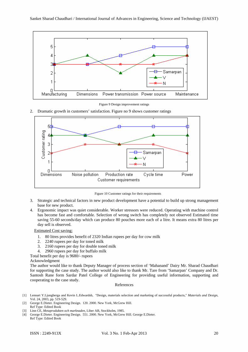
Figure 9 Design improvement ratings
2. Dramatic growth in customers’ satisfaction. Figure no 9 shows customer ratings
Figure 10 Customer ratings for their requirements
3. Strategic and technical factors in new product development have a potential to build up strong management base for new product.
4. Ergonomic impact was quiet considerable. Worker stressors were reduced. Operating with machine control has become fast and comfortable. Selection of wrong switch has completely not observed Estimated time saving 55-60 seconds/day which can produce 80 pouches more each of a litre. It means extra 80 litres per day sell is observed.
Estimated Cost saving: 1. 80 litres provides benefit of 2320 Indian rupees per day for cow milk 2. 2240 rupees per day for toned milk 3. 2160 rupees per day for double toned milk 4. 2960 rupees per day for buffalo milk
Total benefit per day is 9680/- rupees Acknowledgment The author would like to thank Deputy Manager of process section of ‘Mahanand’ Dairy Mr. Sharad Chaudhari for supporting the case study. The author would also like to thank Mr. Tare from ‘Samarpan’ Company and Dr. Santosh Rane form Sardar Patel College of Engineering for providing useful information, supporting and cooperating to the case study.
References
[1] Lennart Y.Ljungberga and Kevin L.Edwardsb, "Design, materials selection and marketing of successful products," Materials and Design, Vol. 24, 2003, pp. 519-529.
[2] George E.Dieter. Engineering Design. 120. 2000. New York, McGrew Hill. Ref Type: Edited Book
[3] Linn CE, Metaprodukten och marknaden, Liber AB, Stockholm, 1985. [4] George E.Dieter. Engineering Design. 551. 2000. New York, McGrew Hill. George E.Dieter.
Ref Type: Edited Book
Sanket Sharad Chaudhari / International Journal of Advances in Engineering, Science and Technology (IJAEST)
ISSN : 2249-913X Vol. 3 No. 1 Feb-Apr 2013 20

[5] George E.Dieter. Engineering Design. 69. 2000. New York, McGrew Hill. Ref Type: Edited Book [6] George E.Dieter. Engineering Design. 99. 2000. New York, McGrew Hill. Ref Type: Edited Book [7] Marion, T. J. and Simpson, T. W., "New product development practice application to an early-stage firm: the case of the PaperPro®
StackMaster™," Design studies, 2009, pp. 561-587. [8] Wheelwright, S. C. and Clark, K. B., Leading product development: The managers guide to creating and shaping the enterprise, Free Press.,
New York, 2012. [9] Markham, S. K. and Griffin, A., "The breakfast of champions: Associations between champions and product development environments,
practices and performance," Journal of Product Innovation Management, Vol. 15, 1998, pp. 436-454. [10] Iansiti, M., "Shooting the rapids: Managing product development in turbulent environments," California Management Review, Vol. 38, No.
1, 1995, pp. 37-58. [11] Brown, S. L. and Eisenhardt, K. M., "Product development: Past research, present findings and future decisions," Academy of Management
Review, Vol. 20, No. 2, 1995, pp. 343-378. [12] Schilling, M. A. and Hill, C. W. L., "Managing the new product development process: Strategic imperatives," Academy of Management
Executive, Vol. 12, No. 3, 1998, pp. 67-81. [13] Jassawella, A. R. and Sashittal, H. C., "Strategies of effective new product team leaders.," California Management Review, Vol. 42, No. 2,
2000, pp. 34-51. [14] Lee, J., Lee, J., and Sonder, W. E., "Differences of organizational characteristics in new product development: Crosscultural comparison of
Korea and the US.," Technovation, Vol. 20, No. 9, 2000, pp. 497-508. [15] Griffin, A., "PDMA research on new product development practices: Updating trends and benchmarking best practices.," Journal of
Product Innovation Management, Vol. 14, No. 429, 1997, pp. 458. [16] Loch, C., Stein, L., and Terwiesch, C., "Measuring product development performance in the electronics industry," Journal of Product
Innovation Management, Vol. 13, 1996, pp. 3-20. [17] Parnaby, J., "Design of the new product introduction process to achieve world class benchmarks," A, Science, Measurement and
Technology, Vol. 142, No. 5, 1995. [18] Rothwell, R., "Successful Industrial Innovation: Critical Factors for the 1990s," R&D Management, Vol. 22, 1992, pp. 221-239. [19] Cooper, R. G. and Kleinschmidt, E. J., "Success Factors in New Product Innovation," Industrial Marketing Management, Vol. 16, 1987, pp.
215-233. [20] Cooper, R. G., "Developing new products on time, in time.," Research Technology Management, Vol. 38, No. 5, 1995, pp. 49-57. [21] Crawford, C. M., New Products Management, Irwin, Chicago, 1983. [22] Booz, Allen , and amilton, New Product Management for the 1980s, Booz Allen & Hamilton, New York, 1982. [23] Butler, S.. More Oil on the Wheels. The Financial Times . 7-23-1992. Ref Type: Newspaper [24] Takeuchi, H. and onaka, I.. The New New Product Development Game. Harvard Business Review January/February , 137-146. 1986.
Ref Type: Magazine Article [25] Taylor, A.. How Toyota Copes with Hard Times. Fortune 127[2], 78-81. 1993. Time Incorporated. Ref Type: Magazine Article [26] Zwicky, F., The Morphological method and construction, Vol. Courant Anniversary Volume, Interscience Publisher, New York, 1948. [27] George E.Dieter, Engineering Design, McGrew Hill, New York, 2000, pp. 175. [28] Prabir Sarkar and Amaresh Chakrabarti, "Assessing design creativity," Design studies, Vol. 32, No. 4, 2011. [29] Pugh, S., Creating Innovative Products Using Total design, Addison-Wesley, MA, 1996. [30] Pugh, S., "Total Design," Addison-Wesley, MA, 1990. [31] Clausing, D., Total quality development, ASME Press, New York, 1994. [32] Creveling, C. M. and Jeff Slutsky, D. A., Design for Six Sigma in Technology and Product Development, Prentice Hall, New Jersey, 2003,
pp. 399. [33] George E.Dieter, Engineering Design, McGrew Hill, New York, 2000, pp. 184. [34] George E.Dieter, Engineering Design, McGrew Hill, New York, 2000, pp. 212. [35] Douglas J.Thomas and Paul M.Griffin, "coordinated supply chain management," European Journal of Operational Research, Vol. 94,
1996, pp. 1-15. [36] Dixon, J. R. and Poli, C., Engineering Design and Design for manufacturing, Field stone Publishers, Conway, MA, 1995, pp. 1-8. [37] Ullman, D. G., "The Mechanical Design Process," McGrew Hill, New York, 2009. [38] Edwards, K. L., "Towards more strategic product design for manufacture and assembly: priorities for concurrent engineering," Materials
and Design, Vol. 23, No. 7, 2002. [39] George E.Dieter, Engineering Design, McGrew Hill, New York, 2000, pp. 399. [40] George E.Dieter, Engineering Design, McGrew Hill, New York, 2000, pp. 403. [41] Rexhausen, D., Pibernik, R., and Kaiser, G., "Customer-facing supply chain practices—The impact of demand and distribution management
on supply chain success," Journal of Operations Management, Vol. 30, No. 4, 2012. [42] Sanders, M. S. and McCormick, E., Human factors in engineering design, McGraw Hill, New York, 1993. [43] Woodson W E., Human factors design handbook: information and guidelines for the design of systems, facilities, equipment and products
for human use., 2d ed., McGraw Hill, New York, 1992.
Sanket Sharad Chaudhari / International Journal of Advances in Engineering, Science and Technology (IJAEST)
ISSN : 2249-913X Vol. 3 No. 1 Feb-Apr 2013 21