products - edwards eng clh-560-a clm-900-w clm-900-a cll series: -50º – -100º lct dts series:...
TRANSCRIPT

101 Alexander Ave., Pompton Plains, NJ 07444 Data subject to change without notice. (800) 468-3826, (973) 835-3222 fax © 2007 Chiller Solutions LLC www.edwards-eng.com All rights reserved.
C h i l l e r s CA Series: 35º – 55º LCT CF Series: 35º – 55º LCT CE Series: 35º – 55º LCT CLH Series: 15º – -15º LCT CLM Series: -10º – -70º LCT
Models Models Models Models Models
CA-10-W CA-10-R CF-3-W CF-3-A CE-3-W CE-3-A CLH-6-W CLH-3-A CLM-5-W CLM-5-A CA-15-W CA-15-R CF-5-W CF-5-A CE-5-W CE-5-A CLH-10-W CLH-5-A CLM-8-W CLM-8-A CA-20-W CA-20-R CF-7-W CF-7-A CE-7-W CE-7-A CLH-14-W CLH-7-A CLM-12-W CLM-12-A CA-30-W CA-30-R CF-10-W CF-10-A CE-10-W CE-10-A CLH-20-W CLH-12-A CLM-16-W CLM-16-A CA-45-W CA-45-R CF-12-W CF-12-A CE-12-W CE-12-A CLH-24-W CLH-17-A CLM-20-W CLM-20-A CA-60-W CA-60-R CF-15-W CF-15-A CE-15-W CE-15-A CLH-30-W CLH-25-A CLM-25-W CLM-25-A
CF-20-W CF-20-A CE-20-W CE-20-A CLH-40-W CLH-30-A CLM-30-W CLM-30-A CF-25-W CF-25-A CE-25-W CE-25-A CLH-50-W CLH-37-A CLM-80-W CLM-80-A CF-30-W CF-30-A CE-30-W CE-30-A CLH-60-W CLH-50-A CLM-100-W CLM-100-A CF-35-W CF-35-A CE-35-W CE-35-A CLH-70-W CLH-62-A CLM-120-W CLM-120-A CF-40-W CF-40-A CE-40-W CE-40-A CLH-80-W CLH-75-A CLM-140-W CLM-140-A
CE-50-W CE-50-A CLH-100-W CLH-87-A CLM-160-W CLM-160-A CM Series: 35º – 55º LCT CE-60-W CE-60-A CLH-120-W CLH-100-A CLM-200-W CLM-200-A
Models CE-70-W CE-70-A CLH-140-W CLH-125-A CLM-240-W CLM-240-A CE-80-W CE-80-A CLH-160-W CLH-150-A CLM-280-W CLM-280-A
CM-10-W CM-10-R CE-90-W CE-90-A CLH-180-W CLH-175-A CLM-320-W CLM-320-A CM-15-W CM-15-R CE-120-W CE-120-A CLH-240-W CLH-200-A CLM-360-W CLM-360-A CM-20-W CM-20-R CE-150-W CE-150-A CLH-300-W CLH-225-A CLM-480-W CLM-480-A CM-30-W CM-30-R CE-180-W CE-180-A CLH-360-W CLH-300-A CLM-600-W CLM-600-A CM-45-W CM-45-R CE-210-W CE-210-A CLH-420-W CLH-375-A CLM-720-W CLM-720-A CM-60-W CM-60-R CE-225-W CE-225-A CLH-450-W CLH-450-A CLM-840-W CLM-840-A
CLH-560-W CLH-560-A CLM-900-W CLM-900-A
CLL Series: -50º – -100º LCT DTS Series: 35º – 55º LCT Models Models
Solvent Vapor Recovery CLL-5-W CLL-5-A DTS-3-W DTS-3-A CLL-10-W CLL-10-A DTS-5-W DTS-5-A Models CLL-15-W CLL-15-A DTS-7-W DTS-7-A CLL-25-W CLL-25-A DTS-10-W DTS-10-A SVR-100-ST SVR-100-DT SVR-100-TT CLL-35-W CLL-35-A DTS-12-W DTS-12-A SVR-200-ST SVR-200-DT SVR-200-TT CLL-50-W CLL-50-A DTS-15-W DTS-15-A SVR-400-ST SVR-400-DT SVR-400-TT CLL-60-W CLL-60-A DTS-20-W DTS-20-A SVR-1000-ST SVR-1000-DT SVR-1000-TT CLL-75-W CLL-75-A DTS-25-W DTS-25-A SVR-2000-ST SVR-2000-DT SVR-2000-TT
CLL-100-W CLL-100-A DTS-30-W DTS-30-A SVR-3000-ST SVR-3000-DT SVR-3000-TT CLL-125-W CLL-125-A DTS-35-W DTS-35-A CLL-150-W CLL-150-A DTS-40-W DTS-40-A Re-Cogen/Gasoline Vapor Recovery CLL-175-W CLL-175-A DTS-50-W DTS-50-A CLL-200-W CLL-200-A DTS-60-W DTS-60-A Model Model CLL-250-W CLL-250-A DTS-70-W DTS-70-A CLL-300-W CLL-300-A DTS-80-W DTS-80-A DE-800 RE-800 CLL-350-W CLL-350-A DTS-90-W DTS-90-A DE-1600 RE-1600 CLL-400-W CLL-400-A DTS-120-W DTS-120-A DE-3200 RE-3200 CLL-450-W CLL-450-A DTS-150-W DTS-150-A DE-7800 RE-7800 CLL-600-W CLL-600-A DTS-180-W DTS-180-A DE-9600 RE-9600 CLL-750-W CLL-750-A DTS-210-W DTS-210-A DE-19200 RE-19200 CLL-900-W CLL-900-A DTS-225-W DTS-225-A
CLL-1050-W CLL-1050-A CLL-1125-W CLL-1125-A
T E T C O G e o t h e r m a l
ESII-1.0-DSH ES-1.0 ESX-1.0 PH-3.0 A-26 C-24-H ESII-1.5-DSH ES-1.5 ESX-1.5 PH-3.5 A-38 C-36-H ESII-2.0-DSH ES-2.0 ESX-2.0 PH-4.0 A-50 C-60-H ESII-2.5-DSH ES-2.5 ESX-2.5 PH-4.5 A-62 ESII-3.0-DSH ES-3.0 ESX-3.0 PH-5.0 ESII-3.5-DSH ES-3.5 ESX-3.5 PH-5.5 A-26-HW E24 ESII-4.0-DSH ES-4.0 ESX-4.0 A-38-HW E30 ESII-4.5-DSH ES-4.5 ESX-4.5 A-50-HW ESII-5.0-DSH ES-5.0 ESX-5.0 A-62-HW ESII-5.5-DSH ES-5.5 ESX-5.5
Models
Products

101 Alexander Ave., Pompton Plains, NJ 07444 Data subject to change without notice. (800) 468-3826, (973) 835-3222 fax © 2007 Chiller Solutions LLC www.edwards-eng.com All rights reserved.
Available Options • Piping manifold kit • Plug and play reservoir tank • Plug and play pump package • Electrical distribution panel and enclosure • MCS operating system, LON/BAC • PLC operating system • Color touch screen display
• Heavy duty mounting skid package • Voltage/ phase protector • Flow switch (per module or system) • Flow meter (turbine style) • Integrated ON/OFF actuators • Condenser water regulating valve • Compressor noise attenuation enclosure
“The M series is designed to provide a modular and scalable solution to your cooling needs. The M series is configured in 10, 15, 30, 45, and 60 HP modules that may stand alone or be intercon-nected. Each M series module is designed to easily fit through a standard 36” door and on most eleva-tors. Each module is complete with operating and safety controls.”
Standard Features
• Staged operating and safety controls • Power alarm/indicator lights • Six-point digital temperature display • Oil filled refrigerant pressure gauges • Plug and freeze resistant heat exchangers
• Filter drier, sight glass, & TXV • Compressors with integral accumulator • Compressors with isolation valves • Complete component access from front • Laser engraved placards and electrical
CM - Se r i e s Modular Scroll Chillers
• 10, 15, 30, 45, & 60 HP MODULES • STAND ALONE OR CONNECTABLE TO 540 HP • WATER OR REMOTE AIR-COOLED CONDENSERS • ULTRA-COMPACT DESIGN FOR EASY INSTALLATION • STAINLESS STEEL AND ALUMINUM CONSTRUCTION • HIGH EFFICIENCY INDUSTRIAL SCROLL COMPRESSORS • COIL IN SHELL EVAPORATORS RESIST PLUGGING • ONBOARD SAFETY AND OPERATING CONTROLS • SINGLE POINT ELECTRICAL CONNECTION • PLUG AND PLAY TANKS, PUMPS, AND CONTROLS • PIPING MANIFOLD KITS TO 8” • COMPLETE COMPONENT ACCESS FROM FRONT
Design Features

101 Alexander Ave., Pompton Plains, NJ 07444 Data subject to change without notice. (800) 468-3826, (973) 835-3222 fax © 2007 Chiller Solutions LLC www.edwards-eng.com All rights reserved.
Layout and Design Assistance: Chiller Solutions 3D design program allows for simple arrangement of the CM series chillers and integrated options with minimal time and effort. This assistance allows the installation to be ideally fit into each applica-tion. Chiller Solutions provides a complete bill of materi-als, quotation, and CAD drawings for the application in a short amount of time.
Modular Water Cooled Chiller
Model Physical Dimensions
Capacity @ 85ºF LCWT (1,000’s BTUH) Water
Connection Shipping Weight
Unit MCA (460/3/60)
35ºF LCT 44ºF LCT 55ºF LCT
CM-10-W 20”L x 24”W x 60”H 97 119 144 1-1/4” 430 lbs. 20
CM-15-W 20”L x 30”W x 65”H 143 177 214 1-1/2” 640 lbs. 30
CM-30-W 35”L x 32”W x 65”H 286 353 427 2” 1300 lbs. 50
CM-45-W 50”L x 32”W x 65”H 430 538 641 2-1/2” 1900 lbs. 80
CM-60-W 68”L x 32”W x 65”H 572 706 854 3” 2500 lbs. 100
Modular Air Cooled Chiller For use with the ACC Series
Model Physical Dimensions
Capacity @ 95ºF Ambient (1,000’s BTUH) Water
Connection Shipping Weight
Unit MCA (460V/3/60)
35ºF LCT 44ºF LCT 55ºF LCT
CM-10-R 20”L x 24”W x 40”H 90 110 133 1-1/4” 325 lbs. 20
CM-15-R 20”L x 30”W x 46”H 131 162 197 1-1/2” 495 lbs. 30
CM-30-R 35”L x 32”W x 46”H 261 323 393 2” 985 lbs. 60
CM-45-R 50”L x 32”W x 46”H 392 509 590 2-1/2” 1475 lbs. 90
CM-60-R 68”L x 32”W x 46”H 522 646 786 3” 1970 lbs. 110
Remote Air Cooled Condenser For use with M-R Series Indoor and Outdoor
Model Physical Dimension
Liquid/Discharge
Connection Shipping Weight
Unit MCA (460V/3/60)
ACC-10 65” L x 39” W 40” H 165 5/8” / 7/8” 300 lbs. 10
ACC-15 65” L x 80” W 40” H 245 7/8” / 1-1/8” 385 lbs. 10
ACC-30 84” L x 40” W 40” H 490 1-1/8” / 1-5/8” 675 lbs. 20
ACC-45 84” L x 40” W 40” H 740 1-3/8” / 2-1/8” 990 lbs. 30
ACC-60 84” L x 84” W 40” H 985 1-5/8” / 2-1/8” 1275 lbs. 40
Condensing Capacity @ 95ºF Ambient
(1,000’s BTUH)
CM - Se r i e s Modular Scroll Chillers

101 Alexander Ave., Pompton Plains, NJ 07444 Data subject to change without notice. (800) 468-3826, (973) 835-3222 fax © 2007 Chiller Solutions LLC www.edwards-eng.com All rights reserved.
M W-S er ies Water Source Heat Pump
Available Options • Piping manifold kit • Plug and play reservoir tank • Plug and play pump package • Electrical distribution panel and enclosure • MCS operating system, LON/BAC • PLC operating system • Color touch screen display
• Heavy duty mounting skid package • Voltage/ phase protector • Flow switch (per module or system) • Refrigerant Reversing Valve • Integrated ON/OFF actuators • Condenser water regulating valve • Compressor noise attenuation enclosure
“The MW series is designed to provide a modular and scalable solution to your heating and cooling needs. The MW series is configured in 10, 15, 30, 45, and 60 HP modules that may stand alone or be interconnected. Each MW series module is designed to easily fit through a standard 36” door and on most elevators. Each module is complete with operating and safety controls.”
Standard Features
• Staged operating and safety controls • Power alarm/indicator lights • Six-point digital temperature display • Oil filled refrigerant pressure gauges • Plug and freeze resistant heat exchangers
• Filter drier, sight glass, & TXV • Compressors with integral accumulator • Compressors with isolation valves • Complete component access from front • Laser engraved placards and electrical
• 10, 15, 30, 45, & 60 HP MODULES • STAND ALONE OR CONNECTABLE TO 540 HP • CLOSED OR OPEN LOOP SYSTEMS • ULTRA-COMPACT DESIGN FOR EASY INSTALLATION • STAINLESS STEEL AND ALUMINUM CONSTRUCTION • HIGH EFFICIENCY INDUSTRIAL SCROLL COMPRESSORS • COIL IN SHELL EVAPORATORS RESIST PLUGGING • ONBOARD SAFETY AND OPERATING CONTROLS • SINGLE POINT ELECTRICAL CONNECTION • PLUG AND PLAY TANKS, PUMPS, AND CONTROLS • PIPING MANIFOLD KITS TO 8” • COMPLETE COMPONENT ACCESS FROM FRONT
Design Features

101 Alexander Ave., Pompton Plains, NJ 07444 Data subject to change without notice. (800) 468-3826, (973) 835-3222 fax © 2007 Chiller Solutions LLC www.edwards-eng.com All rights reserved.
M W-S er ies Selection Data
Layout and Design Assistance: Chiller Solutions 3D design program allows for simple arrangement of the M series chillers and integrated options with minimal time and effort. This assistance allows the installation to be ideally fit into each applica-tion. Chiller Solutions provides a complete bill of materi-als, quotation, and CAD drawings for the application in a short amount of time.
Modular Water Source Heat Pump
Model
Heating Capacity @ 40ºF EWT
(1,000’s BTUH)
Operating Watts @ 40ºF EWT (1,000’s Watts)
COP @ 40ºF EWT
100ºF LWT 110ºF LWT 120ºF LWT 100ºF LWT 110ºF LWT 120ºF LWT 100ºF LWT 110ºF LWT 120ºF LWT
W-10-RGHP 145 142 138 8.492 9.544 10.732 4.9 4.3 3.7
W-15-RGHP 197 194 189 12.773 14.281 15.970 4.5 4.0 3.5
W-30-RGHP 394 388 378 25.550 28.562 31.940 4.5 4.0 3.5
W-45-RGHP 591 582 567 38.323 42.843 47.910 4.4 4.0 3.4
W-60-RGHP 788 776 756 51.096 57.124 63.880 4.4 4.0 3.4
Model Cooling Capacity@ 50ºFEWT
(1,000’s BTUH) Operating Watts @ 50ºF EWT
(1,000’s Watts) EER @ 50ºF EWT
50ºF LCT 45ºF LCT 40ºF LCT 50ºF LCT 45ºF LCT 40ºF LCT 50ºF LCT 45ºF LCT 40ºF LCT
M-10-W 142 118 95 6.167 6.207 6.248 23.85 22.39 20.29
M-15-W 219 199 180 9.400 9.371 9.342 23.67 21.35 19.29
M-30-W 438 398 360 18.800 18.742 18.684 23.34 21.19 19.05
M-45-W 657 597 540 28.256 28.113 28.026 23.73 21.21 19.28
M-60-W 876 796 720 37.697 37.484 63.880 23.38 21.31 19.09
Model Water
Connec-tion
Shipping Weight
Unit MCA
(460/3/60)
Unit MCA
(230/3/60)
Unit MCA
(208/3/60)
Unit MCA
(460/3/60) Water 80/20 60/40
W-10-RGHP 20 25 1-1/4” 430 lbs. 20 40 45 20
W-15-RGHP 30 36 45 1-1/2” 640 lbs. 30 60 70 30
W-30-RGHP 60 72 90 2” 1300 lbs. 50 100 115 50
W-45-RGHP 90 108 135 2-1/2” 1900 lbs. 80 160 180 80
W-60-RGHP 120 144 180 3” 2500 lbs. 100 200 230 100
GPM Required @ Capacity
30

101 Alexander Ave., Pompton Plains, NJ 07444 Data subject to change without notice. (800) 468-3826, (973) 835-3222 fax © 2007 Chiller Solutions LLC www.edwards-eng.com All rights reserved.
Available Options • System pump pressure bypass valve • Bypass Pump • Variable speed system pump • Remote air cooled condenser • Water cooled condensers with mod. Valve • Tank level alarm/switch • Auto-tank fill pressure reducing valve • Flow switch
• Semi-hermetic reciprocating compressor • Locking casters • Voltage/ phase protector • Door mounted disconnect switch • Remote operating/monitoring panel • 6-point digital temperature display • Oil filled refrigerant pressure gauges • R-134a, R407c, R-410a, R-507a
The CF series is designed to provide portable process chilled water where you need it. The compact cabinet dimensions allow you to move the unit through standard door openings and set the chiller close to the process. This fully packaged system includes a robust and high efficiency refrigera-tion circuit which includes industrial style scroll compressors. The integrated tank, pump, and controls make set up and operation of the chiller easy and reliable.
Standard Features
• Industrial scroll compressor with accumulator • Filter drier, sight glass, TXV, and evaporator • Insulated pressurized stainless steel storage tank • Tank sight glass, relief valve, air vent, and fill • System pump with integrated bypass circuit
• Electro-mechanical simple controls • Modulating condenser fan / composite prop • Full refrigerant charge • Super corrosion resistant design • Laser engraved placards and diagrams
• 1/2 TON TO 40 TON STANDARD MODULAR DESIGNS • RANGE FROM 20º F TO 70º F COOLANT TEMP • LARGE PRESSURIZED STAINLESS STEEL RESERVOIR TANK • SYSTEM PUMP WITH INTEGRATED BYPASS CIRCUIT • STANDARD OPERATING AND SAFETY CONTROLS • PACKAGED AIR, WATER, OR REMOTE AIR COOLED • BREAKERS AND MOTOR PROTECTORS– (NO FUSES) • REMOVABLE PANELS FOR EASY SERVICE ACCESS • EXTREME DUTY STAINLESS STEEL FAN SHROUD • MODULATING CONDENSER FAN AND COMPOSITE PROP • VENTILATED CONTROL CABINET WITH HINGED ACCESS • INDOOR/ OUTDOOR OPERATION
Design Features
C F - Se r i e s Portable Fluid Chillers

Layout and Design Assistance: Chiller Solutions 3D design program allows for sim-ple arrangement of the CF series chillers and inte-grated options with minimal time and effort. This assistance allows the installation to be ideally fit into each application. Chiller Solutions provides a complete bill of materials, quotation, and CAD drawings for the application in a short amount of time.
Portable Air Cooled Chillers
Model Physical Dimensions
Unit MCA
(460/3/60)
Capacity @ 95ºF Ambient (1,000’s BTUH)
Reservoir Capacity
(gal)
Pump Flow (gpm)
Inlet / Outlet Size 35ºF LCT 45ºF LCT 55ºF LCT
CF-3-A 40” L x 30” W x 55” H 20 27 34 43 30 10 1” 550 lbs.
CF-5-A 40” L x 30” W x 55” H 30 41 53 66 30 15 1“ 600 lbs.
CF-7-A 48” L x 32” W x 62” H 30 63 78 95 50 20 1-1/4” 800 lbs.
CF-10-A 48” L x 32” W x 62” H 30 90 110 133 50 30 1-1/4” 900 lbs.
CF-12-A 64” L x 39” W x 72” H 40 108 133 163 75 35 1-1/2” 1,300 lbs.
CF-15-A 64” L x 39” W x 72” H 40 131 162 197 75 45 1-1/2” 1,400 lbs.
CF-20-A 84” L x 39” W x 90” H 50 178 219 266 90 60 2” 1,650 lbs.
CF-25-A 84” L x 39” W x 90” H 60 215 267 325 90 70 2” 1,750 lbs.
CF-30-A 128”L x 39” W x 94”H 80 261 323 393 110 90 3” 2,150 lbs.
CF-35-A 128”L x 39”W x 94”H 90 308 381 463 110 100 3” 2,250 lbs.
CF-40-A 128”L x 39”W x 94”H 100 350 433 526 130 110 3” 2,350 lbs.
Shipping Weight
Portable Water Cooled Chillers
Model Physical Dimensions
Unit MCA
(460/3/60)
Capacity @ 85ºF LCWT (1,000’s BTUH)
Reservoir Capacity
(gal)
Pump Flow (gpm)
Inlet / Outlet Size 35ºF LCT 45ºF LCT 55ºF LCT
CF-3-W 40”L x 30”W x 30”H 20 28 38 49 30 10 1” 500 lbs.
CF-5-W 40”L x 30”W x 30”H 30 43 56 70 30 15 1“ 550 lbs.
CF-7-W 48”L x 35”W x 36”H 30 69 85 102 50 20 1-1/4” 750 lbs.
CF-10-W 48”L x 35”W x 40”H 30 97 119 144 50 30 1-1/4” 850 lbs.
CF-12-W 64”L x 35”W x 40”H 30 118 145 176 75 35 1-1/2” 1,250 lbs.
CF-15-W 64”L x 35”W x 40”H 40 143 177 214 75 45 1-1/2” 1,350 lbs.
CF-20-W 64”L x 35”W x 40”H 50 194 239 288 90 60 2” 1,600 lbs.
CF-25-W 128”L x 35”W x 50”H 60 235 290 351 90 70 2” 1,700 lbs.
CF-30-W 128”L x 35”W x 50”H 80 286 353 427 110 90 3” 2,100 lbs.
CF-35-W 128”L x 35”W x 50”H 80 337 415 502 110 100 3” 2,200 lbs.
CF-40-W 128”L x 35”W x 50”H 90 383 472 572 130 110 3” 2,300 lbs.
Shipping Weight
*System pumps designed for rated flow @ 40 PSI, other ranges are available. *Water Cooled units require 2 GPM per ton condenser water flow.
C F - Se r i e s Selection Data

101 Alexander Ave., Pompton Plains, NJ 07444 Data subject to change without notice. (800) 468-3826, (973) 835-3222 fax © 2007 Chiller Solutions LLC www.edwards-eng.com All rights reserved.
Available Options • Variable speed system pump with controller • Auto-fill tank with pressure reducing valve • Tank level alarm/switch • Flow meter with digital display/ analog output • Open loop tank/pump option • Stainless steel panels and hardware
• Variable speed system pump • Voltage/ phase protector • Flow switch (per module or system) • Integrated ON/OFF actuators • Remote operating/monitoring panel • 10 to 40 ton with “Walk-in” enclosure
The CE series provides a complete chiller solution to your process cooling requirements. The CE Series fully packages the refrigeration system, tank, pumps, operating and safety controls, and options onto one skid for simple installation, commissioning and operation. The 3D design allows for the CE series to easily integrate options that otherwise would need to be packaged separately.
Standard Features
• Screw, scroll, or reciprocating compressors • Filter drier, sight glass, TXV, and evaporator • Modulating condenser fan with composite prop • Insulated 15 PSI stainless steel storage tank • Tank sight glass, relief valve, air vent, and fill • System and bypass pumps
• Electro-mechanical simple controls • Door mounted disconnect switch • Oil filled refrigerant pressure gauges • 6-point digital temperature display • Laser engraved placards and diagrams • UL-508 Electrical
• 2 TONS TO 300 TONS AIR OR WATER COOLED • 10ºF TO 80ºF LEAVING COOLANT TEMPERATURES • LARGE STAINLESS STEEL 15 PSI TANK • SYSTEM AND BYPASS PUMPS WITH OPTIONAL VARI-SPEED • SCREW, SCROLL, OR RECIPROCATING COMPRESSORS • SINGLE POINT WIRING FOR ENTIRE SYSTEM • SKID MOUNTED AND PACKAGED FOR EASY INSTALLATION • MODULATING CONDENSER FANS WITH COMPOSITE PROPS • WEATHERPROOF MECHANICAL AND ELECTRICAL SECTIONS • MULTIPLE “COIL IN SHELL” EVAPORATORS RESIST FOULING • “WALK-IN” EQUIPMENT ENCLOSURES FROM 50 TO 300 HP • MULTIPLE EXPLOSION PROOF CLASSIFICATIONS AVAILABLE
Design Features
C E- Se r i e s Fully Packaged Chillers

101 Alexander Ave., Pompton Plains, NJ 07444 Data subject to change without notice. (800) 468-3826, (973) 835-3222 fax © 2007 Chiller Solutions LLC www.edwards-eng.com All rights reserved.
Layout and Design Assistance: Chiller Solutions 3D design program allows for simple arrange-ment of the CE series chillers and integrated options with mini-mal time and effort. This assistance allows the installation to be ideally fit into each application. Chiller Solutions provides a com-plete bill of materials, quotation, and CAD drawings for the appli-cation in a short amount of time.
Packaged Air Cooled Chillers
Model Physical Dimensions
Unit MCA
(460/3/60)
Capacity @ 95ºF Ambient (1,000’s BTUH)
Reservoir Capacity
(gal)
Pump Flow (gpm)
Inlet / Outlet Size
Shipping Weight
35ºF LCT 45ºF LCT 55ºF LCT
CE-3-A 40” L x 30” W x 55” H 20 27 34 43 30 10 1” 550 lbs.
CE-5-A 40” L x 30” W x 55” H 30 41 53 66 30 15 1“ 600 lbs.
CE-7-A 48” L x 32” W x 62” H 30 63 78 95 50 20 1-1/4” 800 lbs.
CE-10-A 48” L x 32” W x 62” H 30 90 110 133 50 30 1-1/4” 900 lbs.
CE-12-A 64” L x 39” W x 72” H 40 108 133 163 75 35 1-1/2” 1,250 lbs.
CE-15-A 64” L x 39” W x 72” H 40 131 162 197 75 45 1-1/2” 1,350 lbs.
CE-20-A 84” L x 39” W x 90” H 50 178 219 266 90 60 2” 1,650 lbs.
CE-25-A 84” L x 39” W x 90” H 60 215 267 325 90 70 3” 1,750 lbs.
CE-30-A 72’ L x 72” W x 80” H 80 261 324 393 110 100 3” 3,800 lbs.
CE-35-A 72’ L x 72” W x 80” H 90 308 381 463 110 110 3” 4,000 lbs.
CE-40-A 84’ L x 84” W x 93” H 100 350 433 526 130 120 3” 4,400 lbs.
Packaged Air Cooled Chillers Walk-in Enclosure
Model Physical Dimensions
Unit MCA
(460/3/60)
Capacity @ 95ºF Ambient (1,000’s BTUH)
Reservoir Capacity
(gal)
Pump Flow (gpm)
Inlet / Outlet Size
Shipping Weight
35ºF LCT 45ºF LCT 55ºF LCT
CE-50-A 8’ L x 8” W x 10’ H 120 430 534 650 150 150 3-1/2” 6,500 lbs.
CE-60-A 8’ L x 8’ W x 10’H 160 522 646 786 150 150 3-1/2” 6,750 lbs.
CE-70-A 12’ L x 8’ W x 10’H 180 616 760 926 250 200 4” 7,500 lbs.
CE-80-A 12’ L x 8’ W x 10’H 200 700 866 1052 250 200 4” 8,000 lbs.
CE-90-A 16’ L x 8‘ W x 10‘H 240 783 969 1179 350 270 4” 9,000 lbs.
CE-120-A 16’ L x 8‘ W x 10‘H 300 1050 1299 1578 350 350 5” 10,500 lbs.
CE-150-A 22’ L x 8‘ W x 10‘H 360 1232 1524 1852 500 450 5” 13,000 lbs.
CE-180-A 22’ L x 8‘ W x 10‘H 480 1566 1938 2358 500 450 5” 15,000 lbs.
CE-210-A 28’ L x 8‘ W x 10‘H 560 1827 2261 2751 700 700 6” 17,000 lbs.
CE-240-A 28’ L x 8‘ W x 10‘H 640 2088 2584 3144 700 700 6” 19,000 lbs.
CE-270-A 32’ L x 8’ W x 10’H 720 2349 2907 3537 900 700 6” 21,000 lbs.
CE-300-A 32’ L x 8’ W x 10’H 800 2610 3230 3930 900 700 6” 23,000 lbs.
CE-45-A 84’ L x 84” W x 93” H 110 392 485 590 130 130 3” 4,700 lbs.
C E- Se r i e s Selection Data

101 Alexander Ave., Pompton Plains, NJ 07444 Data subject to change without notice. (800) 468-3826, (973) 835-3222 fax © 2007 Chiller Solutions LLC www.edwards-eng.com All rights reserved.
Available Options • Variable speed system pump with controller • Auto-fill tank with pressure reducing valve • Tank level alarm/switch • Flow meter with digital display/ analog output • Open loop tank/pump option • Stainless steel panels and hardware
• Variable speed system pump • Voltage/ phase protector • Flow switch (per module or system) • Integrated ON/OFF actuators • Remote operating/monitoring panel • 10 to 40 ton with “Walk-in” enclosure
The DTS series provides a complete chiller solution to your 100% redundant process cooling requirements. The DTS Series fully packages the refrigeration system, tank, pumps, operating and safety controls, and options onto one skid for simple installation, commissioning and operation. The 3D design allows for the CE series to easily integrate options that otherwise would need to be pack-aged separately.
Standard Features
• Screw, scroll, or reciprocating compressors • Filter drier, sight glass, TXV, and evaporator • Modulating condenser fan with composite prop • Insulated 15 PSI stainless steel storage tank • Tank sight glass, relief valve, air vent, and fill • System and bypass pumps
• Electro-mechanical simple controls • Door mounted disconnect switch • Oil filled refrigerant pressure gauges • 6-point digital temperature display • Laser engraved placards and diagrams • UL-508 Electrical
• 3 TONS TO 300 TONS AIR OR WATER COOLED • 10ºF TO 80ºF LEAVING COOLANT TEMPERATURES • LARGE STAINLESS STEEL 15 PSI TANK • SYSTEM AND BYPASS PUMPS WITH OPTIONAL VARI-SPEED • SCREW, SCROLL, OR RECIPROCATING COMPRESSORS • SINGLE POINT WIRING FOR ENTIRE SYSTEM • SKID MOUNTED AND PACKAGED FOR EASY INSTALLATION • MODULATING CONDENSER FANS WITH COMPOSITE PROPS • WEATHERPROOF MECHANICAL AND ELECTRICAL SECTIONS • MULTIPLE “COIL IN SHELL” EVAPORATORS RESIST FOULING • “WALK-IN” EQUIPMENT ENCLOSURES FROM 50 TO 300 HP • MULTIPLE EXPLOSION PROOF CLASSIFICATIONS AVAILABLE
Design Features
D T S - S e r i e s Fully Packaged Chillers

101 Alexander Ave., Pompton Plains, NJ 07444 Data subject to change without notice. (800) 468-3826, (973) 835-3222 fax © 2007 Chiller Solutions LLC www.edwards-eng.com All rights reserved.
Layout and Design Assistance: Chiller Solutions 3D design program allows for simple arrange-ment of the CE series chillers and integrated options with mini-mal time and effort. This assistance allows the installation to be ideally fit into each application. Chiller Solutions provides a com-plete bill of materials, quotation, and CAD drawings for the appli-cation in a short amount of time.
Packaged Air Cooled Chillers
Model Physical Dimensions
Unit MCA
(460/3/60)
Capacity @ 95ºF Ambient (1,000’s BTUH)
Reservoir Capacity
(gal)
Pump Flow (gpm)
Inlet / Outlet Size
Shipping Weight
35ºF LCT 45ºF LCT 55ºF LCT
DTS-3-A 48” L x 32” W x 62” H 20 27 34 43 30 10 1” 1,100 lbs.
DTS-5-A 48” L x 32” W x 62” H 30 41 53 66 30 15 1“ 1,150 lbs.
DTS-7-A 64“L x 48“ W x 62” H 30 63 78 95 50 20 1-1/4” 1,600 lbs.
DTS-10-A 64“L x 48“ W x 62” H 30 90 110 133 50 30 1-1/4” 1,800 lbs.
DTS-12-A 72“ L x 72“ W x 80” H 40 108 133 163 75 35 1-1/2” 2,500 lbs.
DTS-15-A 72“L x 72“ W x 80” H 40 131 162 197 75 45 1-1/2” 2,700 lbs.
DTS-20-A 84“L x 84“ W x 93” H 50 178 219 266 90 60 2” 3,200 lbs.
DTS-25-A 84“L x 84“ W x 93” H 60 215 267 325 90 70 3” 3,400 lbs.
DTS-30-A 144’ L x 72” W x 80” H 80 261 323 393 110 100 3” 7,000 lbs.
DTS-35-A 144’ L x 72” W x 80” H 90 308 381 463 110 110 3” 7,500 lbs.
DTS-40-A 168” L x 84” W x 93” H 100 350 433 526 130 120 3” 8,000 lbs.
Packaged Air Cooled Chillers Walk-in Enclosure
Model Physical Dimensions
Unit MCA
(460/3/60)
Capacity @ 95ºF Ambient (1,000’s BTUH)
Reservoir Capacity
(gal)
Pump Flow (gpm)
Inlet / Outlet Size
Shipping Weight
35ºF LCT 45ºF LCT 55ºF LCT
DTS-50-A 16’ L x 8” W x 10’ H 120 430 534 650 150 150 2-1/2” 13,000 lbs.
DTS-60-A 16’ L x 8’ W x 10’H 160 522 646 786 150 150 3” 14,500 lbs.
DTS-70-A 24’ L x 8’ W x 10’H 180 616 760 926 250 200 3” 16,000 lbs.
DTS-80-A 24’ L x 8’ W x 10’H 200 700 866 1052 250 200 3” 18,000 lbs.
DTS-90-A 32’ L x 8‘ W x 10‘H 240 783 969 1179 350 270 3” 20,000 lbs.
DTS-120-A 32’ L x 8‘ W x 10‘H 300 1050 1299 1578 350 350 3” 22,000 lbs.
DTS-150-A 24’ L x 16‘ W x 10‘H 360 1232 1524 1852 500 450 3” 25,000 lbs.
DTS-180-A 24’ L x 16‘ W x 10‘H 480 1566 1938 2358 500 450 3” 28,000 lbs.
DTS-210-A 24’ L x 24‘ W x 10‘H 560 1827 2261 2751 700 700 4” 35,000 lbs.
DTS-240-A 24’ L x 24‘ W x 10‘H 640 2088 2584 3144 700 700 4” 40,000 lbs.
DTS-270-A 32’ L x 32’ W x 10’H 720 2349 2907 3537 900 700 4” 45,000 lbs.
DTS-300-A 32’ L x 32’ W x 10’H 800 2610 3230 3930 900 700 4” 50,000 lbs.
DTS-45-A 168” L x 84” W x 93” H 110 392 485 590 130 130 3” 8,500 lbs.
D T S - S e r i e s Selection Data
101 Alexander Ave., Pompton Plains, NJ 07444 Data subject to change without notice. (800) 468-3826, (973) 835-3222 fax © 2007 Chiller Solutions LLC www.edwards-eng.com All rights reserved.
Available Options • System pump pressure bypass valve • Mounted Casters • Vibration isolation floor mounts • Auto-fill tank • Tank level alarm/switch • Stainless steel panels and hardware
• Variable speed system pump • Voltage/ phase protector • Flow switch (per module or system) • Integrated ON/OFF actuators • Remote operating/monitoring panel • Hot gas by-pass
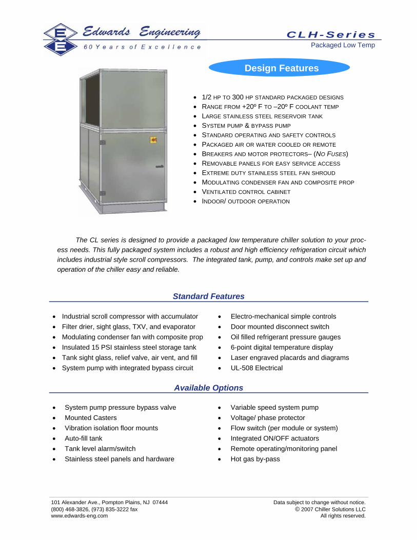
The CL series is designed to provide a packaged low temperature chiller solution to your proc-ess needs. This fully packaged system includes a robust and high efficiency refrigeration circuit which includes industrial style scroll compressors. The integrated tank, pump, and controls make set up and operation of the chiller easy and reliable.
Standard Features
• Industrial scroll compressor with accumulator • Filter drier, sight glass, TXV, and evaporator • Modulating condenser fan with composite prop • Insulated 15 PSI stainless steel storage tank • Tank sight glass, relief valve, air vent, and fill • System pump with integrated bypass circuit
• Electro-mechanical simple controls • Door mounted disconnect switch • Oil filled refrigerant pressure gauges • 6-point digital temperature display • Laser engraved placards and diagrams • UL-508 Electrical
• 1/2 HP TO 300 HP STANDARD PACKAGED DESIGNS • RANGE FROM +20º F TO –20º F COOLANT TEMP • LARGE STAINLESS STEEL RESERVOIR TANK • SYSTEM PUMP & BYPASS PUMP • STANDARD OPERATING AND SAFETY CONTROLS • PACKAGED AIR OR WATER COOLED OR REMOTE • BREAKERS AND MOTOR PROTECTORS– (NO FUSES) • REMOVABLE PANELS FOR EASY SERVICE ACCESS • EXTREME DUTY STAINLESS STEEL FAN SHROUD • MODULATING CONDENSER FAN AND COMPOSITE PROP • VENTILATED CONTROL CABINET • INDOOR/ OUTDOOR OPERATION
Design Features
C L H - S e r i e s Packaged Low Temp

101 Alexander Ave., Pompton Plains, NJ 07444 Data subject to change without notice. (800) 468-3826, (973) 835-3222 fax © 2007 Chiller Solutions LLC www.edwards-eng.com All rights reserved.
Layout and Design Assistance Chiller Solutions 3D design program allows for simple arrangement of the CLH series chillers and integrated op-tions with minimal time and effort. This assistance allows the installation to be ideally fit into each application. Chiller Solutions provides a complete bill of materials, quotation, and CAD drawings for the application in a short amount of time.
Low Temperature Air Cooled Chiller
Model Physical Dimensions
Capacity @ 95ºF Ambient (1,000’s BTUH)
Supply/Return
Pipe Size
Reservoir Capacity
(gal) Shipping Weight
Suggested Fuse Size
(460/3/60) +15ºF LCT 0ºF LCT -15ºF LCT
CLH-2-A 40”L x 30”W x 55”H 10.3 6.6 3.6 1-1/4" 30 3,200 lbs. 10 AMP
CLH-3-A 40”L x 30”W x 55”H 17.8 11.2 3.2 1-1/4" 30 3,200 lbs. 10 AMP
CLH-5-A 40”L x 30”W x 55”H 24.8 15.7 8.7 1-1/4" 30 3,300 lbs. 20 AMP
CLH-7-A 40”L x 30”W x 55”H 37.9 25.1 16.2 1-1/2" 30 3,300 lbs. 20 AMP
CLH-10-A 40”L x 30”W x 55”H 50.0 32.6 20.5 1-1/2" 30 4,000 lbs. 20 AMP
CLH-15-A 56”L x 32” W x 62”H 69.9 46.2 27.9 1-1/2" 50 4,200 lbs. 30 AMP
CLH-20-A 56”L x 32” W x 62”H 86 57 36 2" 50 4,500 lbs. 30 AMP
CLH-25-A 56”L x 32” W x 62”H 99 66 41 2" 50 4,800 lbs. 40 AMP
CLH-30-A 64”L x 39” W x 72”H 115 80 49 2" 75 5,000 lbs. 40 AMP
CLH-40-A 64”L x 39” W x 72”H 154 104 66 2” 75 5,300 lbs. 50 AMP
CLH-50-A 128”L x 39”W x 90”H 204 140 89 2” 100 5,500 lbs. 70 AMP
CLH-60-A 128”L x 39”W x 90”H 239 163 106 2” 100 6,500 lbs. 70 AMP
CLH-70-A 128”L x 39”W x 90”H 278 190 123 3” 100 7,000 lbs. 70 AMP
CLH-80-A 128”L x 39”W x 94”H 318 217 141 3” 100 7,500 lbs. 80 AMP
CLH-90-A 128”L x 39”W x 94”H 359 246 159 3” 100 9,000 lbs. 90 AMP
CLH-120-A 128”L x 39”W x 94”H 462 312 198 3” 100 9,500 lbs. 120 AMP
C L H - S e r i e s Selection Data

101 Alexander Ave., Pompton Plains, NJ 07444 Data subject to change without notice. (800) 468-3826, (973) 835-3222 fax © 2007 Chiller Solutions LLC www.edwards-eng.com All rights reserved.
Available Options • System pump pressure bypass valve • Mounted Casters • Vibration isolation floor mounts • Auto-fill tank • Tank level alarm/switch • Stainless steel panels and hardware
• Variable speed system pump • Voltage/ phase protector • Flow switch (per module or system) • Integrated ON/OFF actuators • Remote operating/monitoring panel • Hot gas by-pass
The CLH series is designed to provide a packaged low temperature chiller solution to your proc-ess needs. This fully packaged system includes a robust and high efficiency refrigeration circuit which includes industrial style scroll compressors. The integrated tank, pump, and controls make set up and operation of the chiller easy and reliable.
Standard Features
• Filter drier, sight glass, TXV, and evaporator • Modulating condenser fan with composite prop • Insulated 15 PSI stainless steel storage tank • Tank sight glass, relief valve, and air vent • System pump with integrated bypass circuit • Electro-mechanical simple controls
• Door mounted disconnect switch • Oil filled refrigerant pressure gauges • 6-point digital temperature display • Laser engraved placards and diagrams • UL-508 Electrical
• 1/2 HP TO 300 HP STANDARD PACKAGED DESIGNS • RANGE FROM +20º F TO –20º F COOLANT TEMP • LARGE STAINLESS STEEL RESERVOIR TANK • SYSTEM PUMP & BYPASS PUMP • STANDARD OPERATING AND SAFETY CONTROLS • WATER COOLED • BREAKERS AND MOTOR PROTECTORS– (NO FUSES) • REMOVABLE PANELS FOR EASY SERVICE ACCESS • INDOOR/ OUTDOOR OPERATION
Design Features
C L H - S e r i e s Packaged Low Temp

101 Alexander Ave., Pompton Plains, NJ 07444 Data subject to change without notice. (800) 468-3826, (973) 835-3222 fax © 2007 Chiller Solutions LLC www.edwards-eng.com All rights reserved.
Low Temperature Water Cooled Chiller
Model Physical Dimensions
Capacity @ 85ºF WT (1,000’s BTUH)
Supply/Return
Pipe Size
Condenser Water
Pipe Size Shipping Weight
Suggested Fuse Size
(460/3/60) +15ºF LCT 0ºF LCT -15ºF LCT
CLH-2-W 4’9” L x 4’7” W x 5’3” H 11.9 8.0 4.7 1-1/4” 7/8” 790 lbs. 10 AMP
CLH-3-W 4’9” L x 4’7” W x 6’3” H 20.3 12.8 7.8 1-1/4” 3/4” 850 lbs. 10 AMP
CLH-5-W 4’9” L x 4’7” W x 5’8” H 29.4 18.9 11.7 1-1/4” 1” 900 lbs. 10 AMP
CLH-7-W 4’9” L x 4’7” W x 6’1” H 44.8 30.8 20.3 1-1/2” 1” 1350 lbs. 20 AMP
CLH-10-W 4’9” L x 4’7” W x 6’5” H 58.1 38.1 24.8 1-1/2” 1-1/4” 1700 lbs. 20 AMP
CLH-15-W* 8’0” L x 7’0” W x 7’3”H 81.3 54.7 34.8 1-1/2” 2” 2200 lbs. 20 AMP
CLH-20-W* 8’0” L x 7’0” W x 7’3”H 100 67 44 2” 2” 2600 lbs. 30 AMP
CLH-25-W* 8’0” L x 7’0” W x 7’3”H 116 81 53 2” 2-1/2” 3000 lbs. 30 AMP
CLH-30-W* 8’0” L x 7’0” W x 7’3”H 133 95 63 2” 2-1/2” 4700 lbs. 30 AMP
CLH-40-W* 10’0” L x 8’0” W x 8”H 216 148 95 2” 3” 5000 lbs. 50 AMP
CLH-50-W* 10’0” L x 8’0” W x 8”H 256 174 110 2” 3” 5500 lbs. 70 AMP
CLH-60-W* 10’0” L x 8’0” W x 8”H 326 222 142 2” 3” 6000 lbs. 70 AMP
CLH-70-W* 12’0” L x 8’0” W x 8”H 380 259 165 2” 3” 7500 lbs. 80 AMP
CLH-120-W* 16’0” L x 8’0” W x 8”H 648 444 287 3” 3” 11,000 lbs. 150 AMP
CL-150-W* 21’0” L x 8’0” W x 8”H 864 592 383 3” 3” 12,000 lbs. 400 AMP
CL-180-W* 21’0” L x 8’0” W x 8”H 1024 692 443 3” 3” 13,000 lbs. 500 AMP
CL-210-W* 24’0” L x 8’0” W x 8”H 1080 740 478.75 3” 3” 14,000 lbs. 600 AMP
CL-240-W* 24’0” L x 8’0” W x 8”H 1280 865 553.75 4” 4” 15,000 lbs. 700 AMP
CL-270-W* 27’0” L x 8’0” W x 8”H 1536 1050 666 4” 4” 16,000 lbs. 800 AMP
CL-300-W* 27’0” L x 8’0” W x 8”H 1792 1211 775 4” 4” 17,500 lbs. 900 AMP
CLH-90-W* 16’0” L x 8’0” W x 8”H 512 350 222 3” 3” 10,000 lbs. 110 AMP
CLH-80-W* 12’0” L x 8’0” W x 8”H 434 296 189 2” 3” 8000 lbs. 110 AMP
Layout and Design Assistance: Chiller Solutions 3D design program allows for simple arrangement of the CLH series chillers and integrated options with minimal time and ef-fort. This assistance allows the installation to be ideally fit into each application. Chiller Solutions provides a complete bill of materials, quotation, and CAD drawings for the application in a short amount of time.
*Walk-In Enclosure
C L H - S e r i e s Selection Data

101 Alexander Ave., Pompton Plains, NJ 07444 Data subject to change without notice. (800) 468-3826, (973) 835-3222 fax © 2007 Chiller Solutions LLC www.edwards-eng.com All rights reserved.
Available Options • System pump pressure bypass valve • Mounted Casters • Vibration isolation floor mounts • Auto-fill tank • Tank level alarm/switch • Stainless steel panels and hardware
• Variable speed system pump • Voltage/ phase protector • Flow switch (per module or system) • Integrated ON/OFF actuators • Remote operating/monitoring panel • Hot gas by-pass
The CLM series is designed to provide a packaged low temperature chiller solution to your proc-ess needs. This fully packaged system includes a robust and high efficiency refrigeration circuit which includes a two stage semi-hermetic reciprocating industrial compressor. The integrated tank, pump, and controls make set up and operation of the chiller easy and reliable.
Standard Features
• Industrial two-stage compound compressor • Filter drier, sight glass, TXV, and evaporator • Modulating condenser fan with composite prop • Insulated 15 PSI stainless steel storage tank • Tank sight glass, relief valve, air vent, and fill • System pump with integrated bypass circuit
• Electro-mechanical simple controls • Door mounted disconnect switch • Oil filled refrigerant pressure gauges • 6-point digital temperature display • Laser engraved placards and diagrams • UL-508 Electrical
• 2 HP TO 30 HP STANDARD PACKAGED DESIGNS • RANGE FROM -10º F TO -60º F COOLANT TEMP • LARGE STAINLESS STEEL RESERVOIR TANK • SYSTEM PUMP & BYPASS PUMP • STANDARD OPERATING AND SAFETY CONTROLS • PACKAGED AIR OR WATER COOLED OR REMOTE • BREAKERS AND MOTOR PROTECTORS– (NO FUSES) • REMOVABLE PANELS FOR EASY SERVICE ACCESS • EXTREME DUTY STAINLESS STEEL FAN SHROUD • MODULATING CONDENSER FAN AND COMPOSITE PROP • VENTILATED CONTROL CABINENT • INDOOR/ OUTDOOR OPERATION
Design Features
C L M - S e r i e s Packaged Low Temp Chillers

101 Alexander Ave., Pompton Plains, NJ 07444 Data subject to change without notice. (800) 468-3826, (973) 835-3222 fax © 2007 Chiller Solutions LLC www.edwards-eng.com All rights reserved.
Consult Factory for Larger Capacity
Layout and Design Assistance: Chiller Solutions 3D design program allows for simple arrangement of the CLM series chillers and integrated options with minimal time and effort. This assistance allows the installation to be ideally fit into each applica-tion. Chiller Solutions provides a complete bill of materials, quotation, and CAD drawings for the application in a short amount of time.
Low Temperature Air Cooled Chiller
Model Physical Dimensions
Capacity @ 95ºF Ambient (1,000’s BTUH)
Supply/Return
Pipe Size
Condenser CFM
Shipping Weight
Suggested Fuse Size
(460/3/60) -10ºF LCT -25ºF LCT -40ºF LCT
CLM-5-A 56”L x 32” W x 62”H 31 22 16 1-1/2" 5,200 900 lbs. 20
CLM-8-A 56”L x 32” W x 62”H 43 32 22 1-1/2" 8,000 1,000 lbs. 40
CLM-12-A 64”L x 39” W x 72”H 66 50 36 2“ 12,000 1,350 lbs. 60
CLM-16-A 64”L x 39” W x 76”H 93 71 52 2" 20,000 1,550 lbs. 60
CLM-20-A 64”L x 39” W x 76”H 107 81 60 3" 28,000 1,650 lbs. 80
CLM-25-A 72”L x 72”W x 80”H 122 93 68 3" 40,000 3,250 lbs. 100
CLM-30-A 8’ L x 84” W x 90” H 144 110 81 3" 48,000 3,450 lbs. 110
CLM-40-A 8’ L x 84” W x 90” H 214 163 119 3" 56,000 3,550 lbs. 150
Low Temperature Water Cooled Chiller
Model Physical Dimensions
Capacity @ 85ºF WT (1,000’s BTUH)
Supply/Return
Pipe Size
Condenser Water
Pipe Size Shipping Weight
Suggested Fuse Size
(460/3/60) -10ºF LCT -30ºF LCT -50ºF LCT
CLM-5-A 56”L x 32” W x 62”H 32 23 17 1-1/2" 1” 900 lbs. 20
CLM-8-A 56”L x 32” W x 62”H 46 33 24 1-1/2" 1-1/4” 1,000 lbs. 30
CLM-12-A 64”L x 39” W x 72”H 70 53 38 2“ 2” 1,350 lbs. 50
CLM-16-A 64”L x 39” W x 76”H 99 75 55 2" 2-1/2” 1,550 lbs. 60
CLM-20-A 64”L x 39” W x 76”H 114 87 63 3" 2-1/2” 1,650 lbs. 80
CLM-25-A 72”L x 72”W x 80”H 130 99 72 3" 2-1/2” 3,250 lbs. 90
CLM-30-A 8’ L x 84” W x 90” H 154 118 86 3" 2-1/2” 3,450 lbs. 110
CLM-40-A 8’ L x 84” W x 90” H 228 174 126 3" 2-1/2” 3,550 lbs. 140
C L M - S e r i e s Selection Data

101 Alexander Ave., Pompton Plains, NJ 07444 Data subject to change without notice. (800) 468-3826, (973) 835-3222 fax © 2007 Chiller Solutions LLC www.edwards-eng.com All rights reserved.
Available Options • System pump pressure bypass valve • Mounted Casters • Vibration isolation floor mounts • Auto-fill tank • Tank level alarm/switch • Stainless steel panels and hardware
• Variable speed system pump • Voltage/ phase protector • Flow switch (per module or system) • Integrated ON/OFF actuators • Remote operating/monitoring panel • Hot gas by-pass
The CLL series is designed to provide a packaged low temperature chiller solution to your proc-ess needs. This fully packaged system includes a robust and high efficiency cascade refrigeration cir-cuit. The integrated tank, pump, and controls make set up and operation of the chiller easy and reli-able.
Standard Features
• Two-stage cascade refrigeration system • Filter drier, sight glass, TXV, and evaporator • Modulating condenser fan with composite prop • Insulated 15 PSI stainless steel storage tank • Tank sight glass, relief valve, air vent, and fill • System pump with integrated bypass circuit
• Electro-mechanical simple controls • Door mounted disconnect switch • Oil filled refrigerant pressure gauges • 6-point digital temperature display • Laser engraved placards and diagrams • UL-508 Electrical
• 2 HP TO 30 HP STANDARD PACKAGED DESIGNS • RANGE FROM -60º F TO -100º F COOLANT TEMP • LARGE STAINLESS STEEL RESERVOIR TANK • SYSTEM PUMP & BYPASS PUMP • STANDARD OPERATING AND SAFETY CONTROLS • PACKAGED AIR OR WATER COOLED OR REMOTE • BREAKERS AND MOTOR PROTECTORS– (NO FUSES) • REMOVABLE PANELS FOR EASY SERVICE ACCESS • EXTREME DUTY STAINLESS STEEL FAN SHROUD • MODULATING CONDENSER FAN AND COMPOSITE PROP • VENTILATED CONTROL CABINENT • INDOOR/ OUTDOOR OPERATION
Design Features
C L L - S e r i e s Packaged Low Temp

101 Alexander Ave., Pompton Plains, NJ 07444 Data subject to change without notice. (800) 468-3826, (973) 835-3222 fax © 2007 Chiller Solutions LLC www.edwards-eng.com All rights reserved.
Layout and Design Assistance: Chiller Solutions 3D design program allows for simple arrangement of the CLL series chillers and integrated options with minimal time and effort. This assistance allows the installation to be ideally fit into each application. Chiller Solutions provides a complete bill of materials, quotation, and CAD drawings for the applica-tion in a short amount of time.
Low Temperature Air Cooled Chiller
Model Physical Dimensions
Capacity @ 95ºF Ambient (1,000’s BTUH)
Supply/Return
Pipe Size
Condenser CFM
Shipping Weight
Suggested Fuse Size
(460/3/60) -60ºF LCT -80ºF LCT -100ºF LCT
CLL-15-A 6” L x 4” W x 6” H 18 11 6 1-1/4” 5,200 2,100 lbs. 30 AMP
CLL-30-A 8”L x 4”W x 8”H 30 23 12 1-1/2” 8,000 2,400 lbs. 40 AMP
CLL-50-A 8’ L x 8” W x 10’ H 64 42 22 2” 12,000 3,900 lbs. 60 AMP
CLL-60-A 8’ L x 8” W x 10’ H 84 51 29 2” 16,000 4,900 lbs. 60 AMP
CLL-70-A 10’ L x 8” W x 10’ H 109 61 41 2” 24,000 5,750 lbs. 70 AMP
CLL-110-A 12’ L x 8’ W x 10’H 150 93 52 2” 32,000 7,200 lbs. 100 AMP
CLL-145-A 12’ L x 8’ W x 10’H 180 110 61 3” 40,000 8,500 lbs. 130 AMP
CLL-155-A 12’ L x 8’ W x 10’H 199 129 80 3” 48,000 9,800 lbs. 140 AMP
Low Temperature Water Cooled Chiller
Model Physical Dimensions
Capacity @ 85ºF WT (1,000’s BTUH)
Supply/Return
Pipe Size
Condenser Water
Pipe Size Shipping Weight
Suggested Fuse Size
(460/3/60) -60ºF LCT -80ºF LCT -100ºF LCT
CLL-15-W 6” L x 4” W x 6” H 20 13 8 1-1/4” 1” 2,400 lbs. 20 AMP
CLL-30-W 8”L x 4”W x 8”H 32 25 14 1-1/2” 1-1/4” 2,700 lbs. 30 AMP
CLL-50-W 10’ L x 8” W x 8’ H 66 44 24 2” 2” 4,200 lbs. 50 AMP
CLL-60-W 10’ L x 8” W x 8’ H 87 54 32 2” 2-1/2” 5,200 lbs. 60 AMP
CLL-70-W 10’ L x 8” W x 8’ H 112 64 44 2” 2-1/2” 6,150 lbs. 70 AMP
CLL-110-W 12’ L x 8’ W x 8’H 153 96 55 2” 2-1/2” 7,500 lbs. 100 AMP
CLL-145-W 12’ L x 8’ W x 8’H 186 116 67 3” 2-1/2” 8,800 lbs. 130 AMP
CLL-155-W 12’ L x 8’ W x 8’H 205 135 86 3” 2-1/2” 9,800 lbs. 130 AMP
C L L - S e r i e s Selection Data

101 Alexander Ave., Pompton Plains, NJ 07444 Data subject to change without notice. (800) 468-3826, (973) 835-3222 fax © 2007 Chiller Solutions LLC www.edwards-eng.com All rights reserved.
How Edwards Vapor Recovery Units Work
Vapors enter the condenser where moisture is removed in the initial section of heat exchange tubes
with widely spaced fins. This spacing design minimized pressure drop and blockage due to frosting.
In the next section of the coil with closely spaced fins, vapors are condensed and collected directly as
liquid. The design and use of a refrigerant direct expansion condensing coil heat exchanger permits
the raising of refrigeration compressor suction pressure, increasing the capacity of the unit at a con-
stant condensing temperature if needed.
At periodic intervals, defrosting of the finned surfaces may be required; defrosting is accomplished by
circulating warm heat transfer fluid, stored in a separate reservoir, and the circulation of warm proc-
essed air. The temperature of the fluid and the air is maintained by heat reclamation from the refrigera-
tion equipment. No shut down time is required for defrosting in the vapor recovery unit if the dual con-
denser option is utilized.
Vapor Recovery Systems Recover 99% or greater of
Most Solvents or Hydrocarbons with
Edwards Vapor Recovery Units.
• Simplicity– Vapors piped directly into the condens-
ing chamber are recovered as liquid condensate
without intermediate steps or additional treatments.
• Cleanliness– Liquid condensation occurs directly on
cold metal surfaces and drips into a collecting cham-
ber with no addition of contaminants.
• Safety– The condensation process is continuous,
completely safe, and usually occurs at temperatures
far below the flash point.
• Economy– Low capital and installation costs; low
maintenance and operating costs; rapid payback: sell
or reuse recovered liquid.

101 Alexander Ave., Pompton Plains, NJ 07444 Data subject to change without notice. (800) 468-3826, (973) 835-3222 fax © 2007 Chiller Solutions LLC www.edwards-eng.com All rights reserved.
SVR Series • Chemical Processing • Pharmaceutical Processing • General Industrial Applications
Standard factory packaged units recover many common condensable va-
pors directly to liquid for reuse in processing. Custom design modification
are made readily at the factory upon review of the particular composition of
the vapor stream. Units in operation for the past 15 years achieve recovery
rates greater than 95%
Closed Loop Vapor Recovery: Closed loop vapor recovery is attractive when applied to drying towers, ovens, and spray dyers. Edwards SVR Series Vapor Re-
covery Units greatly reduce the energy required to heat the inlet product stream by recovery approximately 70% of the sensible
cooling load. This approach has the highest recovery efficiency of any recovery system.
DE Series
• Gasoline Bulk Stations • Truck Loading • Storage Tanks • Barges and Tankers
Developed specifically for the gasoline and hydrocarbon field, the DE series
achieves 95% to 99% gasoline vapor recovery. Recovered liquid hydrocarbons
can be sold or reused. In many cases short-term capital cost recovery is real-
ized due to the value of the recovered liquid.
LN2 Series
• Cool Vapors as low as -300ºF • Achieve recovery rates of 99% or greater • Meet or exceed the most stringent government vapor
recovery requirements
Stand Alone LN2— The LN2 unit can function alone as a condensation-
based vapor recovery unit, cooling vapors to -300ºF and achieving a recov-
ery rate of 95% to 99% or greater. This option is intended primarily for rela-
tively low volume flow rates or for intermittent or infrequent use.
Retrofit LN2— The LN2 unit can be added as a component to an existing
vapor recovery system to achieve higher rates of recovery and to meet strin-
gent code limits.
Cryo-Mechanical— The LN2 unit can be combined with any Edwards mechanical refrigeration vapor recovery unit in a complete
factory package. This option is intended for new ore replacement installation with high volume flow rates and frequent or continu-
ous process use.
Vapor Recovery Systems

101 Alexander Ave., Pompton Plains, NJ 07444 Data subject to change without notice. (800) 468-3826, (973) 835-3222 fax © 2007 Chiller Solutions LLC www.edwards-eng.com All rights reserved.
Standard Features and Available Options Factory Packaged: All Edwards Vapor Recovery Units are delivered directly to the job-site, factory packaged and skid mounted. Custom modifications can b e made at the factory to meet on-site operating needs and performance specifications.
Walk-In Enclosure: The refrigeration machinery is located in a weatherproof metal walk-in enclosure, providing ample room for operation, maintenance and service.
Low Operating Costs/Energy Savings: Edwards electrically operated vapor recovery packages feature LOW energy consumption per volume of liquid recovered. Units also are designed to recover sensible cooling from the effluent stream, and rejected heat from compressors can be used for defrosting.
Low Maintenance/Long Life: Direct condensation of vapors at atmospheric pressure requires no preliminary or intermediate compression or vapor storage. The basic refrigeration system follows conventional circuit design, is easy to maintain, and lasts indefinitely.
Fully Automatic Operation: A single panel controls operation from inside the unit, so full-time attendance is not required. Remote operation also is available.
Direct Meter Record of Liquid Recovery: An optional direct reading indicator provides a cumulative record of the recovered condensate.
Recovered Condensate is Reusable: Simple piping can be used to return the recovered condensate to any con-venient location. Condensed water vapor also can be separated from water immiscible solvents and piped to other locations.
Dual Condensing Coils Available: Where continuous production, loading or processing operation is desired, this option eliminates the need to shut down equipment for defrosting.
100% Overload Capacity: In a refrigeration based unit, the suction pressure of the compressors automatically rises with the load; raising the suction pressure results in increased refrigeration capacity of the unit.
Solvent Vapor Recovery For:
• Chemical Processing • Pharmaceutical Processing • General Industrial Applications
SVR systems re used to recover condensable vapors directly to liquid for reuse in processing. The SVR closed loop vapor recovery system is desirable for drying towers, ovens, and spray dryers. These units greatly reduce the energy required to heat the inlet product stream by recovering approximately 70% of the sensible cooling load. This approach has the highest recovery efficiency of any recovery system.
S V R - S e r i e s Solvent Vapor Recovery
101 Alexander Ave., Pompton Plains, NJ 07444 Data subject to change without notice. (800) 468-3826, (973) 835-3222 fax © 2007 Chiller Solutions LLC www.edwards-eng.com All rights reserved.
Layout and Design Assistance: Chiller Solutions 3D design program allows for simple ar-rangement of the SVR series chillers and integrated options with minimal time and effort. This assistance allows the in-stallation to be ideally fit into each application. Chiller Solu-tions provides a complete bill of materials, quotation, and CAD drawings for the application in a short amount of time.
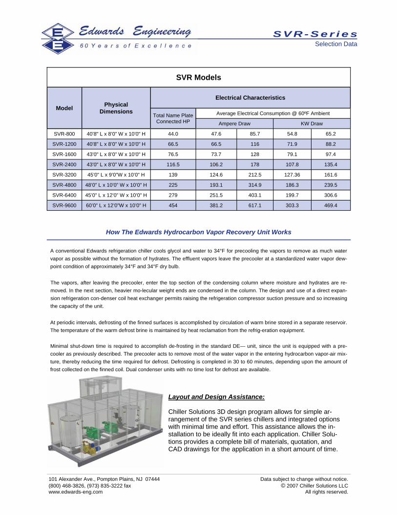
How The Edwards Hydrocarbon Vapor Recovery Unit Works A conventional Edwards refrigeration chiller cools glycol and water to 34°F for precooling the vapors to remove as much water vapor as possible without the formation of hydrates. The effluent vapors leave the precooler at a standardized water vapor dew-point condition of approximately 34°F and 34°F dry bulb. The vapors, after leaving the precooler, enter the top section of the condensing column where moisture and hydrates are re-moved. In the next section, heavier mo-lecular weight ends are condensed in the column. The design and use of a direct expan-sion refrigeration con-denser coil heat exchanger permits raising the refrigeration compressor suction pressure and so increasing the capacity of the unit. At periodic intervals, defrosting of the finned surfaces is accomplished by circulation of warm brine stored in a separate reservoir. The temperature of the warm defrost brine is maintained by heat reclamation from the refrig-eration equipment. Minimal shut-down time is required to accomplish de-frosting in the standard DE— unit, since the unit is equipped with a pre-cooler as previously described. The precooler acts to remove most of the water vapor in the entering hydrocarbon vapor-air mix-ture, thereby reducing the time required for defrost. Defrosting is completed in 30 to 60 minutes, depending upon the amount of frost collected on the finned coil. Dual condenser units with no time lost for defrost are available.
SVR Models
Physical Dimensions
Electrical Characteristics
Total Name Plate Connected HP
Average Electrical Consumption @ 60ºF Ambient
Ampere Draw KW Draw
SVR-800 40’8" L x 8’0” W x 10’0" H 44.0 47.6 85.7 54.8 65.2
SVR-1200 40’8" L x 8’0” W x 10’0" H 66.5 66.5 116 71.9 88.2
SVR-1600 43’0" L x 8’0” W x 10’0" H 76.5 73.7 128 79.1 97.4
SVR-2400 43’0" L x 8’0” W x 10’0" H 116.5 106.2 178 107.8 135.4
SVR-3200 45’0" L x 9’0”W x 10’0" H 139 124.6 212.5 127.36 161.6
SVR-4800 48’0" L x 10’0” W x 10’0" H 225 193.1 314.9 186.3 239.5
SVR-6400 45’0" L x 12’0” W x 10’0" H 279 251.5 403.1 199.7 306.6
SVR-9600 60’0" L x 12’0”W x 10’0" H 454 381.2 617.1 303.3 469.4
Model
S V R - S e r i e s Selection Data

101 Alexander Ave., Pompton Plains, NJ 07444 Data subject to change without notice. (800) 468-3826, (973) 835-3222 fax © 2007 Chiller Solutions LLC www.edwards-eng.com All rights reserved.
DE Series for use in: • Gasoline Bulk Stations • Truck Loading • Storage Tanks • Barges and Tankers
Developed specifically for the gasoline and hy-drocarbon field, the DE series achieves 95% to 99% gasoline vapor recovery. Recovered liquid hydrocarbons can be sold or reused. In many case short term capital cost recovery is realized due to the value of the recovered liquid.
Standard Features and Available Options Simple Fully Automatic Operation Operation of the complete unit is fully controlled from the single panel within the enclosure. All functions are automatic. The Ed-wards Vapor Recovery Units are furnished with automatic controls which provide operation without full time attendance. Remote operation with safety controls is available as an option. Low Maintenance Cost Recovery of condensable vapors is accomplished by passing vapor-air mixtures over cold heat transfer surfaces, resulting in the direct condensation of hydrocarbon vapors at atmospheric pressure. No preliminary or intermediate compression of vapors is re-quired, thus simplifying the equipment required and reducing maintenance. The maintenance costs are reasonable.
Fully Factory Packaged to Your Specifications Factory packaged units are available with various custom modifications to meet on-site specifications. The standard enclosure is designed to be mounted on a concrete pad. All operating components are mounted on a heavy duty steel base frame- ready to place on site. Most of the refrigeration machinery, is located within a weather-proof, fire-resistant enclosure. Pick-up lugs are pro-vided for rigging purposes.
Recovered Liquid Hydrocarbon Can Be Pumped to Any Location Piping can be used to automatically return the condensed liquid hydrocarbons from the insulated condenser package directly to any convenient location. Condensed water vapor is separated from the condensed hydrocarbons and can be piped to the terminal waste water disposal facilities.
All Components Weather-proof or Enclosed All working components and electrical controls are either of weather-proof construction or are housed in a weather-proof enclosure constructed of galvanized steel panels. This enclosure provides full room for attending personnel to enter for routine maintenance and service. Wiring Meets Explosion-proof Codes The Edwards Hydrocarbon Recovery Unit is constructed as ordered by the customer to meet any local code requirements. All wir-ing is complete and may include, if ordered and requested by the customer, a main disconnect switch mounted within the enclo-sure.
Long Equipment Life The cascade refrigeration system follows conventional circuit design with an almost indefinite life.
D E- Se r i e s

101 Alexander Ave., Pompton Plains, NJ 07444 Data subject to change without notice. (800) 468-3826, (973) 835-3222 fax © 2007 Chiller Solutions LLC www.edwards-eng.com All rights reserved.
Layout and Design Assistance: Chiller Solutions 3D design program allows for simple ar-rangement of the DE series chillers and integrated options with minimal time and effort. This assistance allows the in-stallation to be ideally fit into each application. Chiller Solu-tions provides a complete bill of materials, quotation, and CAD drawings for the application in a short amount of time.
How The Edwards Hydrocarbon Vapor Recovery Unit Works A conventional Edwards refrigeration chiller cools glycol and water to 34°F for precooling the vapors to remove as much water vapor as possible without the formation of hydrates. The effluent vapors leave the precooler at a standardized water vapor dew-point condition of approximately 34°F and 34°F dry bulb. The vapors, after leaving the precooler, enter the top section of the condensing column where moisture and hydrates are re-moved. In the next section, heavier mo-lecular weight ends are condensed in the column. The design and use of a direct expan-sion refrigeration con-denser coil heat exchanger permits raising the refrigeration compressor suction pressure and so increasing the capacity of the unit. At periodic intervals, defrosting of the finned surfaces is accomplished by circulation of warm brine stored in a separate reservoir. The temperature of the warm defrost brine is maintained by heat reclamation from the refrig-eration equipment. Minimal shut-down time is required to accomplish de-frosting in the standard DE-unit, since the unit is equipped with a precooler as previously described. The precooler acts to remove most of the water vapor in the entering hydrocarbon vapor-air mixture, thereby reducing the time required for defrost. Defrosting is completed in 30 to 60 minutes, depending upon the amount of frost collected on the finned coil. Dual condenser units with no time lost for defrost are available.
DE Models
Physical Dimensions
Electrical Characteristics
Total Name Plate Connected HP
Average Electrical Consumption @ 60ºF Ambient
Ampere Draw KW Draw
DE-800 40’8" L x 8’0” W x 10’0" H 44.0 47.6 85.7 54.8 65.2
DE-1200 40’8" L x 8’0” W x 10’0" H 66.5 66.5 116 71.9 88.2
DE-1600 43’0" L x 8’0” W x 10’0" H 76.5 73.7 128 79.1 97.4
DE-2400 43’0" L x 8’0” W x 10’0" H 116.5 106.2 178 107.8 135.4
DE-3200 45’0" L x 9’0”W x 10’0" H 139 124.6 212.5 127.36 161.6
DE-4800 48’0" L x 10’0” W x 10’0" H 225 193.1 314.9 186.3 239.5
DE-6400 45’0" L x 12’0” W x 10’0" H 279 251.5 403.1 199.7 306.6
DE-9600 60’0" L x 12’0”W x 10’0" H 454 381.2 617.1 303.3 469.4
Model
D E- Se r i e s Selection Data

101 Alexander Ave., Pompton Plains, NJ 07444 Data subject to change without notice. (800) 468-3826, (973) 835-3222 fax © 2007 Chiller Solutions LLC www.edwards-eng.com All rights reserved.
LN2 Series for use in: • Pharmaceutical Applications • Petroleum • Chemical Processing
Edwards Engineering in Cooperation with Praxair, Inc. now offers an additional line of simple, safe, and economical vapor recovery packages now using liquid nitrogen. By cooling vapors to as low as -300ºF with liquid nitrogen, these enhanced vapor recovery packages make it possible to achieve greater recovery rates than mechanical refrigeration alone.
Meets the Most Stringent State & EPA Vapor Recovery Requirements The Clean Air Act The 1990 Clean Air Act established federal guidelines for VOC (volatile organic compounds) emissions and requires industrial sources that exceed those guidelines to reduce emissions by installing a maxi-mum achievable control technology (MACT). Mechanical refrigeration for vapor recovery has proven to be a safe, economical way to deal with VOC and hydrocarbon emissions and to comply with the Clean Air Act guidelines. Regulations Are Getting Tougher A typical mechanical refrigeration vapor recovery system cools vapors to -100°F, where up to 95-98% of most vapors are condensed and recovered directly as liquid. However, new regulations are now man-dating a vapor recovery rate of at least 99% in many areas. The Edwards LN2 Series makes it possi-ble to meet or exceed these new standards by adding a liquid nitrogen component to super-cool vapors to a maximum of -300°F, thereby achieving a recovery rate of 99% or higher in most instances.
Options for Nearly Any Vapor Recovery Requirement • LN2 Retrofit-The Edwards Liquid Nitrogen Unit can be added to any existing vapor recovery sys-
tem to improve recovery efficiency. • Stand-alone LN2 Unit-The liquid nitrogen unit can function by itself as a condensation-based vapor
recovery unit, cool-ing vapors to -300F and achieving a recovery rate of 95-99% or greater. • Edwards Cryo-Mechanical Vapor Recovery Units-Each Edwards mechanical refrigeration vapor
recovery unit now can be combined with an LN2 unit in a complete factory package that achieves a 99%+ vapor recovery rate.
L N 2 - S e r i e s Enhanced Vapor Recovery

101 Alexander Ave., Pompton Plains, NJ 07444 Data subject to change without notice. (800) 468-3826, (973) 835-3222 fax © 2007 Chiller Solutions LLC www.edwards-eng.com All rights reserved.
Layout and Design Assistance: Chiller Solutions 3D design program allows for simple ar-rangement of the DE series chillers and integrated options with minimal time and effort. This assistance allows the in-stallation to be ideally fit into each application. Chiller Solu-tions provides a complete bill of materials, quotation, and CAD drawings for the application in a short amount of time.
L N 2 - S e r i e s Selection Data
LN2 Models
Physical Dimensions
Electrical Characteristics
Total Name Plate Connected HP
Liquid Nitrogen Consumption
-180 KW Draw
LN-800 20’8" L x 8’0” W x 10’0" H 2
LN-1200 20’8" L x 8’0” W x 10’0" H 3
LN-1600 24’0" L x 8’0” W x 12’0" H 4
LN-2400 24’0" L x 8’0” W x 12’0" H 6
LN-3200 28’0" L x 9’0”W x 14’0" H 8
LN-4800 28’0" L x 10’0” W x 14’0" H 12
LN-6400 32’0" L x 10’0” W x 14’0" H 16
LN-9600 36’0" L x 10’0”W x 16’0" H 24
Model
-220
101 Alexander Ave., Pompton Plains, NJ 07444 Data subject to change without notice. (800) 468-3826, (973) 835-3222 fax © 2007 Chiller Solutions LLC www.edwards-eng.com All rights reserved.
How Edwards Boiler Chiller Plants Work Edwards boiler chiller plants are a value engineered product based on your pre-engineered conditions.
Any large office, residential, or industrial facility can be designed to accept these highly efficient cost
effective products. Installation times and costs are highly reduced because of the simplicity of single
point connections. Imagine the cost savings of instead of wiring 10 or more power points, 30 or more
control points, 20 or more plumbing components, and then connecting these all to the building sys-
tems. You have 1 power point, 1 control connection, and 6 plumbing points. Imagine the time savings
in commissioning the system when instead of 3 or 4 contractors being involved, the system has al-
ready been test run in the factory. Imagine the difference when and if there is a component failure,
instead of a who’s who figure pointing escapade, there is a clear knowledgeable individual to call, with
all the pertinent information archived, and readily accessible, regardless of the quality of your in house
record keeping. Now stop imagining because that is an Edwards Boiler Chiller Plant. We can single or
multiple skid Boiler Chiller Plants to fit almost any application. Now just imagine how you will spend all
the time and money your going to save.
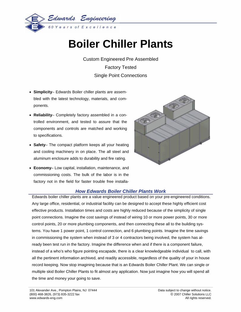
Boiler Chiller Plants Custom Engineered Pre Assembled
Factory Tested
Single Point Connections
• Simplicity– Edwards Boiler chiller plants are assem-
bled with the latest technology, materials, and com-
ponents.
• Reliability– Completely factory assembled in a con-
trolled environment, and tested to assure that the
components and controls are matched and working
to specifications.
• Safety– The compact platform keeps all your heating
and cooling machinery in on place. The all steel and
aluminum enclosure adds to durability and fire rating.
• Economy– Low capital, installation, maintenance, and
commissioning costs. The bulk of the labor is in the
factory not in the field for faster trouble free installa-

101 Alexander Ave., Pompton Plains, NJ 07444 Data subject to change without notice. (800) 468-3826, (973) 835-3222 fax © 2007 Chiller Solutions LLC www.edwards-eng.com All rights reserved.
Condensing Boiler/Chiller Plants
Model Physical Dimensions
Capacity @ 95ºF Ambient (1,000’s BTUH) Water
Connection Shipping Weight
Unit MCA (460/3/60)
35ºF LCT 44ºF LCT 180ºF LCT
CBC2040 8’ L x 8’ W x 10’H 240 280 400 2” 7,750 lbs. 180
CBC4080 12’ L x 8’ W x 10’H 480 560 800 2-1/2” 8,000 lbs. 220
CBC60120 12’ L x 8’ W x 10’H 720 840 1200 3” 9,000 lbs. 240
CBC80160 16’ L x 8‘ W x 10‘H 960 1120 1600 3” 10,000 lbs. 270
CBC100200 16’ L x 8‘ W x 10‘H 1200 1400 2000 4” 11,000 lbs. 360
Heat Pump Boiler/Chiller Plants
Model Physical Dimensions
Capacity @ 95º/55ºF Ambient (1,000’s BTUH) Water
Connection Shipping Weight
Unit MCA (460V/3/60)
35ºF LCT 44ºF LCT 130ºF LHT
HBC2040 8’ L x 8’ W x 10’H 240 280 340 2” 7,750 lbs. 180
HBC4080 12’ L x 8’ W x 10’H 480 560 680 2-1/2” 8,000 lbs. 220
HBC60120 12’ L x 8’ W x 10’H 720 840 1020 3” 9,000 lbs. 240
HBC80160 16’ L x 8‘ W x 10‘H 960 1120 1360 3” 10,000 lbs. 270
HBC100200 16’ L x 8‘ W x 10‘H 1200 1400 1700 4” 11,000 lbs. 360
Geo-Thermal Boiler/Chiller Plants
Model Physical Dimensions
Water Connection
Shipping Weight
Unit MCA (460/3/60)
CBC2040 8’ L x 8’ W x 10’H Cooling 240 / Heating 280 2” 7,750 lbs. 180
CBC4080 12’ L x 8’ W x 10’H Cooling 480 / Heating 560 2-1/2” 8,000 lbs. 220
CBC60120 12’ L x 8’ W x 10’H Cooling 720 / Heating 840 3” 9,000 lbs. 240
CBC80160 16’ L x 8‘ W x 10‘H Cooling 960 / Heating 1120 3” 10,000 lbs. 270
CBC100200 16’ L x 8‘ W x 10‘H Cooling 1200 / Heating 1400 4” 11,000 lbs. 360
Capacity @ 45ºF Ground Source (1,000’s BTUH)
Layout and Design Assistance: Chiller Solutions 3D design program allows for simple arrangement of the Edwards Boiler Chiller Plants and integrated options with minimal time and effort. This assistance allows the installation to be ideally fit into each application. Chiller Solutions provides a complete bill of materials, quotation, and CAD drawings for the application in a short amount of time.