production technology of agricultural machinery
TRANSCRIPT

Production Technology of
Agricultural Machinery
Dr. P. Kamaraj
Dr. V. R. Ramachandran

Production Technology of Agricultural Machinery -: Course Content Developed By :-
Dr. P. Kamaraj
Asst. Professor of Farm Machinery
Agricultural Engineering College and Research Institute,
TNAU, Kumulur
-:Content Reviewed by :-
Dr. V. R. Ramachandran
Professor, Agrl. Engg. Service Centre
Kerala Agricultural University, Kerala

INDEX
Lesson Name Page No MODULE 1. Introduction to production of agricultural machinery
LESSON 1. CRITICAL APPRAISAL IN PRODUCTION OF AGRICULTURAL MACHINERY
5-13
MODULE 2. Advance in material for tractor and agricultural Machinery
LESSON 2. MATERIAL USED FOR TRACTOR AND AGRICULTURAL MACHINERY
14-23
LESSON 3. CUTTING TOOLS 24-31
LESSON 4. CUTTING TOOLS FOR CNC MACHINES 32-38
LESSON 5. CUTTING TOOLS FOR FINISHING OPERATIONS 39-41 MODULE 3. Advanced manufacturing techniques LESSON 6. ADVANCED MANUFACTURING TECHNIQUES 42-46
LESSON 7. ELECTRICAL DISCHARGE MACHINING (EDM) 47-55
LESSON 8. POWDER METALLURGY 56-65 MODULE 4. Heat treatment of steel LESSON 9. HEAT TREATMENT OF STEEL 66-70
LESSON 10. PACK CARBURIZING 71-75
LESSON 11. SHOT PEENING 76-83
LESSON 12 .CHEMICAL VAPOUR DEPOSITION (CVD) 84-90 MODULE 5. Industrial lay out planning and quality management
LESSON 13. LIMITS, FITS AND TOLERANCE 91-99
LESSON 14. MICRO STRUCTURE ANALYSIS OF METALS 100-105
LESSON 15. INDUSTRIAL LAYOUT PLANNING AND QUALITY MANAGEMENT
106-114
LESSON 16. QUALITY MANAGEMENT 115-121 MODULE 6. Economics of process LESSON 17. ECONOMICS OF PROCESS SELECTION 122-126 MODULE 7. Techno economic feasibility of project report LESSON 18. TECHNO ECONOMIC FEASIBILITY OF PROJECT REPORT
127-133
LESSON 19. CASE STUDY ON AGRICULTURAL TINES 134-142

LESSON 20. CASE STUDY OF MANUFACTURING OF WEEDERS
143-155
LESSON 21. CRITICAL COMPONENTS AND THEIR SELECTION
156-175
MODULE 8. Servo motors, drives and controllers LESSON 22. INTRODUCTION OF SERVO MOTORS 176-180
LESSON 23. SERVO MOTORS 181-185 MODULE 10. CNC programming LESSON 24. CNC PROGRAMMING 186-191
LESSON 25. CNC PART PROGRAMMING II 192-198
LESSON 26. CNC PART PROGRAMMING III 199-205

Production Technology of Agricultural Machinery
5 www.AgriMoon.Com
MODULE 1. Introduction to production of agricultural machinery
LESSON 1. CRITICAL APPRAISAL IN PRODUCTION OF AGRICULTURAL MACHINERY
1.1 Introduction
Agriculture in India is unique in its characteristics, where over 250 different crops are cultivated in its varied agro-climatic regions, unlike 25 to 30 crops grown in many of the developed nations of the world. Agriculture is one of the most important sectors of the Indian economy contributing 18.5 per cent of national income, about 15 per cent of total exports and supporting two-thirds of the work force.
India with its favorable agro-climatic conditions and rich natural resource base has become the world's largest producer across a range of commodities.
India is the largest producer of coconuts, mango, banana, milk and dairy products,cashew nuts, pulses, ginger, turmeric and black pepper.
It is also the second largest producer of rice, wheat, sugar, cotton, fruits and vegetables.
Present Food Grain production - After a near-stagnation or modest growth in output for several years, Indian agriculture has officially rebounded in 2007-08 with food grain production surging by 10 million tonnes, or 4.6 per cent, to touch a new high of 227.32 million tonnes. The grain output in 2006-07 was 217.28 million tonnes.
The early agricultural mechanization in India was greatly influenced by the technological developments in England. Horse drawn and steam-tractor-operated equipments were imported during the later part of the nineteenth century. The horse drawn equipments imported from England were not suitable for bullocks and buffaloes being used in India. These were suitably modified to suit Indian draught animals. With the production of indigenous tractors and irrigation pumps, the use of mechanical power in agriculture, has been showing an increasing trend.
As a result of Green Revolution in the sixties, the total food grain production increased from a mere 50.8 million tonnes during 1950-51 to 217 million tonnes in 2006-07, and productivity increased from 522 kg/ha to more than 1,500 kg/ha. The increase in production of food grains was possible as a result of adoption of quality seeds, higher dose of fertilizer and plant protection chemicals. Irrigation played a major role in increasing the productivity. Increased cropping intensity and higher quantity of inputs could no longer be effectively managed by animate power alone and, therefore, farmers adopted tractors, irrigation pumps, harvesters and power threshers extensively.
1.2 Progress of Farm Mechanization in India
The progress of agricultural mechanization has been closely linked with the overall development in production agriculture. Till 1950, very few farmers possessed prime movers

Production Technology of Agricultural Machinery
6 www.AgriMoon.Com
like tractors, engines and motors. Heavy agricultural tractors and machinery were imported by government organizations mainly for land reclamation and development of large government farms.
The picture changed quickly during the early sixties with the introduction of high yielding varieties of wheat and other crops which needed irrigation facilities. The progressive farmers soon realized that the traditional water lifts, which were driven by draught animals or operated manually, could not meet the water requirement of the high yielding varieties of different crops. Lift irrigation was, therefore, quickly mechanized through the use of electric motor or diesel engine powered pumps.
The rising production of foodgrains resulting from the extending area under high yielding varieties could not be handled within the normal harvesting and threshing periods. The farmers in North India suffered heavy losses as a result of damage to harvested wheat during the late sixties and early seventies because the threshing of increased wheat production could not be completed before the onset of pre-monsoon rains. Large scale adoption of threshers operated by electric motors, engines and tractors that followed in early seventies onwards was a result of the need to complete threshing operation quickly. Then came the extensive use of tractors for primary tillage and transport and the use of tractor powered or self-propelled harvesting equipment.
1.3 Production - Indian Scenario
The productivity of farms depends greatly on the availability and judicious use of farm power by the farmers. Agricultural implements and machines enable the farmers to employ the power judiciously for production purposes. Agricultural machines increase productivity of land and labour by meeting timeliness of farm operations and increase work out-put per unit time. Besides its paramount contribution to the multiple cropping and diversification of agriculture, mechanization also enables efficient utilization of inputs such as seeds, fertilizers and irrigation water.
The production of irrigation pumps and diesel engines started during 1930s. The manufacture of tractors and power tillers started in 1960. Since then by the virtue of its inherent edge over the conventional means of farming, agricultural mechanization has been gaining popularity. The increased use of farm machines found expansion of cropped area and cropping intensity and also helped in diversification of agriculture from conventional crops to commercial crops.
The manufacture of agricultural machinery in the country is carried out by village artisans, tiny units, small- scale industries and the State Agro-Industrial Development Corporations.
Production of tractors, motors, engines and process equipment is the domain of the organized sector.
The traditional artisans and small-scale industries rely upon own experience; user's feedback and government owned research and development institutions for technological support and operate from their backyards or on road side establishments without regular utility services.
Production Technology of Agricultural Machinery
7 www.AgriMoon.Com
Medium and large-scale industries operate in their own premises with sound infrastructure, usually forming a part of an industrial estate, wellestablished manufacturing and marketing facilities and employ skilled manpower.
Diesel engines, electric motors, irrigation pumps, sprayers and dusters, land development machinery, tractors, spare parts, power tillers, post harvest and processing machinery and dairy equipments are produced in this sector. They have professional marketing network of dealers and provide effective after sales service. They also have in-house research and development facilities or have joint ventures with advanced countries for technology upgradation. India is recognized, the world over, as a leader in the manufacture of agricultural equipment and machinery such as tractors, combine harvesters, plant protection equipment, drip irrigation and micro-sprinkler. Sizeable quantities of farm implements are exported to Africa, Middle East, Asia, South America and other countries.
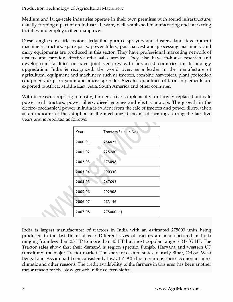
With increased cropping intensity, farmers have supplemented or largely replaced animate power with tractors, power tillers, diesel engines and electric motors. The growth in the electro- mechanical power in India is evident from the sale of tractors and power tillers, taken as an indicator of the adoption of the mechanized means of farming, during the last five years and is reported as follows:
Year Tractors Sale, in Nos
2000-01 254825
2001-02 225280
2002-03 173098
2003-04 190336
2004-05 247693
2005-06 292908
2006-07 263146
2007-08 275000 (e)
India is largest manufacturer of tractors in India with an estimated 275000 units being produced in the last financial year. Different sizes of tractors are manufactured in India ranging from less than 25 HP to more than 45 HP but most popular range is 31- 35 HP. The Tractor sales show that their demand is region specific. Punjab, Haryana and western UP constituted the major Tractor market. The share of eastern states, namely Bihar, Orissa, West Bengal and Assam had been consistently low at 7- 9% due to various socio- economic, agro-climatic and other reasons. The credit availability to the farmers in this area has been another major reason for the slow growth in the eastern states.

Production Technology of Agricultural Machinery
8 www.AgriMoon.Com
Tractor sales in Maharashtra, Tamil Nadu, Karnataka and Andhra Pradesh have been showing consistent growth since mid 1980‘s. This region is expected to contribute more than 30% to the tractor industry in this decade. This expectation is based on the fact that the farmers in this southern region have been adopting high value case crops and latest crop production/ management practices. After a drop in sales in 2006-07 sales have risen in 2007-08.
Territory % age of Domestic Sales
North (Punjab, Haryana & Uttar Pradesh) 29%
Central (Madhya Pradesh & Rajasthan) 21%
East (Bihar, West Bengal, Orissa & Assam) 9%
West (Gujarat & Maharashtra) 15%
South (Andhra Pradesh, Tamil Nadu, Karnataka & Kerala) 26%
Power Tillers:
Year Power Tillers Sale,(In Nos.)
2000-01 16018
2001-02 13563
2002-03 14613
2003-04 15665
2004-05 18985
2005-06 22303
2006-07 13375
2007-08 15000 (e)
The production of power tillers started in 1961 with license to manufacture 12 models. The manufacturers started offering these to farmers in various states covering upland and wetland farming conditions. Their introduction coincided with that of agricultural tractors which were more suitable for upland work and provided more comfortable work environment to the operators.
The power tiller models being manufactured, and also those being imported from China, etc, and being marketed for wetland, stationary and haulage work are being well received by the farmers. The available models have a Drawbar power between 5.3 kW to 10.7 kW. The major Tractors and Farm Equipment Manufacturers in India are

Production Technology of Agricultural Machinery
9 www.AgriMoon.Com
Balwan Tractors, Force Motors Ltd
Captain Tractors Pvt. Ltd
Crossword Agro Industries
Eicher
Escorts (Escort, Powertrac and Farmtrac)
Ford Tractors
HMT Tractors
Indo Farm John Deere
Mahindra Gujarat Tractor Limited
Mahindra & Mahindra
MARS Farm Equipments Ltd.
New Holland
Preet Tractors
Punjab Tractors Ltd (Swaraj Tractors)
Same Deutz-Fahr Ltd.
Sonalika (International Tractors Ltd.)
Standard
TAFE
VST Tillers
1.4 Stationary Power – Diesel Engines & Electric Motors
Electric Motors and Diesel Engines are the primary sources of stationary power for irrigation, threshing and various post-harvest agro-processing operations. Diesel Engine population, which was 1.443 million in 1971-72 increased to 5.528 in 1995-96, and, crossed 7.4 million in 2005-06.
Electric Motor population has increased from 1.535 million in 1971-72 to 7.464 million in 1995-96, and, was 12 million 2005-06.

Production Technology of Agricultural Machinery
10 www.AgriMoon.Com
Population of Power Sources and their power availability in India
Year Diesel Engines Electrical Motors
Million Units Power (kW/ha) Million Units Power (kW/ha)
71-72 1.443 0.053 1.535 0.041
75-76 2.075 0.078 2.064 0.056
81-82 3.061 0.112 3.203 0.084
85-86 3.742 0.139 4.192 0.111
91-92 4.800 0.177 6.019 0.159
95-96 5.528 0.203 7.464 0.196
00-01 6.466 0.238 9.525 0.250
05-06 7.432 0.273 11.866 0.311
The studies on operational efficiency of irrigation pumps have shown the efficiency of electric motor operated pumps to be 31.1% against only 12.7% of diesel engine operated pumps.
1.5 Other Machinery in Operation
1.5.1 Seed Bed Preparation Equipment:
Tractor mounted implements such as mouldboard ploughs, disc ploughs, cultivators and other crop- specific equipment are widely being used for seed bed preparation. Seed drills and planters, both animal drawn and tractor mounted, have become popular. The growth in use of tractor drawn machinery has been in the range of 9-17%.
Different sizes of cultivators and disc harrows are used but due to farm road and terrain constraints, cultivators of more than 15 tines and disc harrows of more than 18 discs are not much in use. The power from higher horse power tractors, therefore, is not fully utilized.
1.5.2 Sowing and planting equipment
The line sowing not only saves seed but also facilitates regulated application of fertilizer near root zone. Besides, it helps control of weeds through use of mechanical weeders. For precise application of seed and fertilizer, mechanically metered seed drills and seedcum- fertilizer drills operated by animals and tractors have been developed and are being manufactured to suit specific crops and regions

Production Technology of Agricultural Machinery
11 www.AgriMoon.Com
Mechanical transplanters for rice and vegetable crops are catching up with farmers. Long handle tools and power weeders for weeding and interculture and manual and power operated sprayers and dusters for application of chemicals have been commercialized.
1.5.3 Harvesting Equipment:
Cereal crop harvesters including various designs of vertical conveyor reaper windrowers and combine harvesters are being used on large scale. Tractor mounted digger- elevators for groundnut and tuber crops are being used. Spike-tooth and raspbar type threshers for cereal crops and crop specific threshers for major crops such as soybean, groundnut, sunflower have been developed and commercialized.
Reapers powered by engines, power tillers and tractors have been developed and introduced for harvesting wheat, paddy, soybean, ragi and mustard. Tractor-powered and self-propelled combine harvesters are being manufactured in India. About 700- 800 combines are sold annually. Track-type Combine harvesters, especially suitable for paddy crop, are also being manufactured locally. The combine harvesting of wheat, paddy and soybean has been well accepted by farmers.
1.6 Regions having major concentration of Agricultural Machinery
Northern region
Ludhiana, Moga, Jalandhar, Goraya, Batala, Hoshiyarpur, Karnal, Panipat,
Faridabad, Delhi, Agra, Ghaziabad, Meerut, Rudrapur, Muzaffarnagar,
Lucknow, Kanpur, Fatehpur and Allahabad.
Western region
Bombay, Pune, Nagpur, Ahmed Nagar, Sangli, Kolhapur, Sholapur,
Ahmedabad, Baroda, Anand, Junagarh, Bhopal, Indore, Dewas, Bina, Khurai,
Raipur, Vidisha and Gwalior.
Southern region
Hyderabad, Guntur, Anantpur, Kakinada, Coimbatore, Madurai, Chennai,
Salem, Palghat, Ernakulam, Kochin and Bangalore.
Eastern region
Calcutta, Vardhaman, Durgapur, Bhubaneswar, Sambhalpur, Patna, Ranchi,
Dhanbad and Muzaffarpur.
1.7 Constraints & Misconceptions

Production Technology of Agricultural Machinery
12 www.AgriMoon.Com
It is misconceived that benefits of mechanization could be reaped only by farmers having large acreage. The Indian farmer, however orthodox he/she may be, has only to be convinced of the relevance of techniques and machinery to induce him to accept them. Equipments for tillage, sowing, irrigation, plant protection and threshing have widely been accepted by them.
Even farmers with small holdings utilize selected improved farm equipment through custom hiring to increase productivity and reduce cost of production. The small plot size might have been an impediment for use of large tractors but not for adoption of small tractors, power tillers and improved machinery. The improved hand tools, animal drawn and tractor operated implements have been adopted more in those states where productivity per unit area has increased.
The State Agro Industries Development Corporations of Madhya Pradesh, Gujarat, Maharashtra, Andhra Pradesh, Rajasthan, Uttar Pradesh, West Bengal, Assam, Orissa and Kerala are already manufacturing improved implements besides local small scale industries.
1.8 Need for increased Mechanisation in India
Mechanization has been well received the world over as one of the important elements of modernization of agriculture. It is now recognized that availability of mechanical power and improved equipment has enabled States like Punjab and Haryana to achieve high levels of land productivity.
The results of the survey conducted under the project ―Study Relating to Formulating Long-Term Mechanization Strategy for Each Agro Climatic Zone/State‖ conducted by the Government of India confirm that in those States where agricultural mechanization has made good progress, its benefits are being shared by all farmers irrespective of the size of their operational holdings and whether they own tractors and machinery or not. However, the progress of mechanization in most of the States has been slow and its benefits of timely and precise operations, efficient use of costly inputs like seed, fertilizer, plant protection chemicals, limited water resource, etc. are not reaching the majority of farmers in full measure.
During the course of project implementation by the Government of India, certain issues need attention to if a more even spread of mechanization and the policy goal of modernizing Indian agriculture have to be achieved.
Future requirement for farm equipment and technologies include rota- tiller for seed bed preparation, till planter, strip till drill, pneumatic precision planter, sugarcane sett cutter planter, vegetable transplanter and check-row planter, for sowing and planting. Power weeders and equipment for chemico-mechanical weed management; electrostatic spraying and tall tree spraying are required. Harvesting equipment for sugarcane and cotton are required to be developed.
Looking at the future requirement of India and its import statistics of agricultural and farm machinery it is clear that Italy is one of the top 5 exporters. But looking at the value of Italy‘s exports to India vis-à-vis India‘s total import of these farm machinery and equipment, it is

Production Technology of Agricultural Machinery
13 www.AgriMoon.Com
clear that there are further potential opportunities for Italian manufacturers to sell and market their agricultural machinery and equipments in India.

Production Technology of Agricultural Machinery
14 www.AgriMoon.Com
MODULE 2. Advance in material for tractor and agricultural Machinery
LESSON 2. MATERIAL USED FOR TRACTOR AND AGRICULTURAL MACHINERY
1.1 Introduction
The development in agricultural engineering has progressed extremely fast during the last decades. The most important milestones after the introduction of the diesel drive can be listed as follows:
combination of several process steps in one machine
oil hydraulic drives and controls
electronic controls
extreme increase in the performance of individual machines
All these obvious innovations easily lead us to oversee a comparatively inconspicuous, but very important development: The further development of the materials of parts and components used in modern agricultural machinery. Not all that long ago, a typical agricultural machine consisted exclusively of ―iron and steel‖ as a rule.
This has changed considerably. The reasons for the use of different materials in modern agricultural machinery are:
higher load on the components due to increased machine performance
in parts, light-weight design is imperative on account of legal regulations and avoidance of soil compaction
increase of the resistance to wear due to higher loads on components and higher area capacities
increased demands on lifetime of modern agricultural machinery
increased demands on design and ergonomics of the machinery.

Production Technology of Agricultural Machinery
15 www.AgriMoon.Com
The progress in various materials will now be described as follows. Based on concrete examples of components taken from the range of KRONE products, modern materials and their properties will be described.
1.2 Material groups
In this chapter the following systematics will be followed:
1. Structural steels
2. Alloyed steels
3. Cast materials
4. Light alloys
5. Wearing materials
6. Synthetic materials
1.2.1 Structural steels
Structural steel is still the classic material for the load-bearing structures of our agricultural machinery. However, in the past the loads on these machine frames have increased as well as the necessity to reduce weight, which has several reasons. The high-performance modern machines are increasingly reaching the weight limits which are set by legal regulations. In Germany, for example, the weight on a driven axle is limited to 11.5 t. But also in smaller machines, such as a round baler, weight limits apply in Germany, such as an axle load of 3 t, as from which the use of an expensive brake system is obligatory.
In order to optimise the carrying capacity of the welded frames and their weight at the same time, KRONE has been using fine-grained structural steel in this field almost exclusively for many years. In this way it is possible to reduce the plate thickness and/or the profile cross section.
The strength of general structural steels can be increased by the addition of carbon. However, they can no longer be welded when a limit of 0.22 % of carbon is exceeded. Fine grained steels, however, retain an especially fine-grained structure even at a low content of carbon due to the special alloying constituents. Thus, they have a higher strength, but they can be welded very well and can also be cold shaped well.

Production Technology of Agricultural Machinery
16 www.AgriMoon.Com
1.2.2 Alloyed steels
Alloyed steels are used in the production of gears, thus for shafts and gear wheels. KRONE uses here very high-quality tempered steels in parts, such as 18CrNiMo 7-6 (#1.6587) and 42CrMo4V (#1.7225). Tensile strengths of up to 1200 N/mm² and hardness to be achieved of 62 HRC permit high loads on the components. High-quality materials enable the production of gear wheels and shafts with smaller dimensions, which along with the smaller gear housings lead to more constructive freedom and weight saving.
But for high-load welded components as well, KRONE uses a special material of this category with the designation K27V. This is a boron-alloyed steel which in a quenched state can be welded well up to a hardness of 50 HRC. Tensile strengths of up to 1100 N/mm² are achieved.
This material is used for the cross-member of the steering axle of the self-propelled mower-conditioner Big M, for example. This heavily loaded component consists of 90 x 40 mm flat steel which is welded to the rear-axle cross-member. In parts, non-corroding steels are also used. They are used wherever rust formation caused by aggressive media has to be prevented, but anti-corrosive coating has no space, however. Another property of this material is used for the Big X forage harvester: The front pre-compression rollers are made of X15CrNiSi2520 (#1.4841) because this material is not magnetisable.
The lower pre-compression roller contains a metal detector which has the task to recognise metal parts in the forage, immediately shutting down the feed system of the forage as protection of the blade drum. As this system is operated on the basis of an induction principle, a roller made of magnetisable steel would shield the sensor, thus making it ineffective.

Production Technology of Agricultural Machinery
17 www.AgriMoon.Com
1.2.3 Cast materials
As they are the classic materials, flake-graphite cast iron (GG), nodular-graphite cast iron (GGG), malleable cast iron (GT) as well as cast steel (GS) are used. For some years now, KRONE has been using a new cast material, namely the so-called ADI cast, the abbreviation of which stands for "austempered ductile iron". ADI is produced by means of a multiple-stage heat treatment of ductile cast iron. Given certain tenacity, ADI offers double the strength of nodular-graphite cast iron. Moreover, ADI has good attenuation properties and a very good anti-wearing behavior. KRONE uses ADI as a material for cam tracks in rotary rakes.
The cam follower rollers of the tine arms run-in this cam track, which takes place under high surface pressure and very dusty conditions. On account of the properties of ADI described, this is possible without lubrication. The positive experience enables KRONE to give a three-year warranty on the wear of the cam track.
1.2.4 Light alloys
Light alloys are used mainly for parts made of aluminum alloys. They are used wherever weight reduction is crucial. The row-independent Easy Collect maize header of KRONE is an example to be mentioned here.

Production Technology of Agricultural Machinery
18 www.AgriMoon.Com
For harvesting maize, the Big X forage harvester is fitted with a front harvesting attachment, which can take up to fourteen rows of maize at the same time. In order to minimize the weight transfer of the rear axle of the forage harvester, it is necessary to keep the weight of the maize header as low as possible. The gear housings of the various drives used in the Easy Collect contribute to this end as they are cast from AlSi7MgO aluminum alloy. At a volume mass of 2.65 g/cm³ this alloy is 2/3 lighter than steel. All in all a weight of about 120 kg is saved for a twelve-row maize header. Another example for the use of aluminum alloys is fitted in the rotary rakes. The bearing housing is made of die cast AlSi10Mg.
The mass reduction of 34 kg in the rotary drive reduces the forces which have to be taken up by the outrigger and the main frame of the swathe, which thus can be made lighter as well. Moreover, a lighter rotor can follow the ground contour better.

Production Technology of Agricultural Machinery
19 www.AgriMoon.Com
1.2.5 Wearing materials
KRONE hay and forage machines are subjected to wear primarily at points which get into intensive contact to the crop, which includes all types of blade, but also sheet metal channels through which the crop is past at high speed. This chapter will render some examples from the forage harvester Big X.
In the forage harvester, the maize is cut between the moving blades of the cutting drum and the stationary counter blade (A in Fig.1.9). On account of the high throughput capacities of these machines, wear occurs after a relatively short period of time. In order to optimize this unit, the blades and counter blades are coated with hard metal in parts.
In a special process, hard particles made of tungsten carbide bedded in a matrix are applied to the surface and primarily to the side edges of the counter blade. These particles have a hardness of up to 2000 VH.
The forage passes through a feed channel chamber (B in Fig.1.9) behind the cutting drum, which is made of Hardox on the lower side to ensure protection against wear. Hardox is sheet-metal material hardened and optimized especially for wear resistance produced by a Swedish manufacturer. By being hardened up to 500 HB and with a tensile strength of up to 1500 N/mm², Hardox ensures a multiple service life compared to normal types of steel in these conditions of use.
There are especially hard conditions for forage harvesters, in which a lot of sand and/or dust is taken in along with the maize. Here the service life of Hardox sheet metals is not enough either. In these cases sheet metals are used which have been armour-plated with a high carbide contents by weld cladding.

Production Technology of Agricultural Machinery
20 www.AgriMoon.Com
Further downstream, the maize then passes the so-called corn cracker, which consists of two fast rotating toothed rollers, which are located at a very close distance to each other. When passing through this gas, the maize corns are squeezed for better digestibility. These rollers are also subjected to a high degree of wear. They are manufactured from a pipe made of material Cf 45N, which is provided with a hardness of about 60 HRC.
1.2.6 Synthetic materials
In modern agricultural machinery, synthetic materials are employed in versatile forms. The most obvious use, however, is certainly the field of machine design.
Today, aesthetically shaped paneling dominates the market. In the automotive industry this target was achieved by deep drawing sheet metal.
At the relatively low unit numbers in agricultural engineering compared to the motor-vehicle industry this cannot be carried out economically. For this reason, paneling made of synthetic material is used.
KRONE produces modern machine paneling made of glass-fiber reinforced plastic. In this process, glass fiber is placed in a mould, saturated with polyester resin and hardening agent.
In the so-called hand laminate process, glass fibre mats are coated by brush. In the more automated fibre spraying process, a special spray gun is used to spray resin, hardening agent and fibre into the mould. On the outside, the parts have a smooth surface ensured by the mould, which can also be dyed in multiple colours.
The inside is rough and can be linked up to laminated steel parts of the machine. This process is suitable for small to medium numbers, and stands out for its high mechanical stability at relatively low investment costs.

Production Technology of Agricultural Machinery
21 www.AgriMoon.Com
A plate or a film made of thermo-plastic material is clamped in a stenter frame, and then a suitable heat source is used to heat both The heated plate is pre-stretched by compressed air, and the moulding tool moves into moulding position by lifting the machine table. The air located between model and plate is drawn off. The atmospheric outside pressure presses the soft plate against the mould walls in such a manner that the contours are precisely copied. Subsequently the moulded material is cooled down by cooling air blower, and compressed air is used for demoulding.
The last process to be presented here shall be the rotational moulding or rotational sintering process for the production of hollow bodies. In this process, a certain amount of fine polyethylene granulate is filled into a mould. The closed mould is then heated permanently rotating around two axes. The synthetic sides until fictile. When the fictile range has been made, the heat sources are removed. Material melts and settles on the inside of the mould at a uniform thickness. Subsequently the rotating mould is cooled down, opened, and the component is demoulded. The diesel tank of Big X, for example, is produced in this way.

Production Technology of Agricultural Machinery
22 www.AgriMoon.Com
On account of the low density of the polyethylene of only 0.93 g/cm³, this 960-litre tank has an empty mass of 60 kg, which is about 140 kg lighter than a comparable steel tank. The rotational moulding process can also be used to manufacture single-shell shapes, such as inside panelling of the cab. They are manufactured in pairs in one mould and are subsequently separated.
1.3. Abstract and outlook
The progress described in the materials of agricultural machinery took place in different periods ranging from some decades to a few years only. The optimization of various materials will certainly continue in the future. A strong development has to be expected, for example, in the metal matrix composite materials described for wear-resistant components. By combining metallic and ceramic materials to a composite, the typical advantages of both material classes can be used, whereby the property profile of the metal matrix / ceramic composite can be set precisely by varying the shape, size and volume percentage of the composite partner. The structure of the ceramic component also determines significantly the properties of the composite.
Moreover, it may also be possible that entirely new materials, so-called smart materials, which are being used in other branches already, may be introduced to agricultural engineering: piezoelectric materials, for example, are suitable for the production of components which can be shaped by applying electrical current.

Production Technology of Agricultural Machinery
23 www.AgriMoon.Com
Piezoelectric materials have two unique properties which are interrelated. When a piezoelectric material is deformed, it gives off a small but measurable electrical charge. Alternately, when an electrical current is passed through a piezoelectric material it experiences a significant increase in size (up to a 4 % change in volume).
Today already, this material is being used in the motor-vehicle industry, for example, as sensors for air bags or as actuators in the injection system. In agricultural engineering, it is theoretically conceivable, for example, to adapt the shape of a deep-digger body to various soil conditions or working speeds by electrical current.
The so-called shape memory alloys also belong to the smart materials. Shape memory alloys (SMA's) are metals, which exhibit two very unique properties, pseudo-elasticity, and the shape memory effect. The most effective and widely used alloys include NiTi (Nickel - Titanium), CuZnAl, and CuAlNi.
The special feature in this alloy is that a phase twinned martensite is used, in which by heat the alloy is converted into another phase austenite without the component changing its size or shape. If a component made of twinned martensite is deformed by excessively high loads,
it can be returned to its original shape by heating.
Even if this technology certainly is relatively far away from use in everyday agricultural practice, deformed components which after an excessively load can be returned to their original shape by simple heating, would indeed by another distinct progress in typical materials for agricultural machinery

Production Technology of Agricultural Machinery
24 www.AgriMoon.Com
LESSON 3. CUTTING TOOLS
3.1 Introduction
The cutting tool materials must possess a number of important properties to avoid excessive wear, fracture failure and high temperatures in cutting. The following characteristics are essential for cutting materials to withstand the heavy conditions of the cutting process and to produce high quality and economical parts:
3.1.1 Hardness
At elevated temperatures (so-called hot hardness) so that hardness and strength of the tool edge are maintained in high cutting temperatures. From Fig.3.1 shows hot hardness for different tool materials.
Fig.3.1 Hot hardness for different tool materials (Ref. Book by A.Bhattacharya)
3.1.2 Toughness
Ability of the material to absorb energy without failing. Cutting if often accompanied by impact forces especially if cutting is interrupted, and cutting tool may fail very soon if it is not strong enough.
3.1.3 Wear resistance
Although there is a strong correlation between hot hardness and wear resistance, later depends on more than just hot hardness. Other important characteristics include surface finish on the tool, chemical inertness of the tool material with respect to the work material, and thermal conductivity of the tool material, which affects the maximum value of the cutting temperature at tool-chip interface.

Production Technology of Agricultural Machinery
25 www.AgriMoon.Com
3.2 Needs and chronological development of cutting tool materials
With the progress of the industrial world it has been needed to continuously develop and improve the cutting tool materials and geometry;
to meet the growing demands for high productivity, quality and economy of machining
to enable effective and efficient machining of the exotic materials that are coming up with the rapid and vast progress of science and technology
for precision and ultra-precision machining
for micro and even nano machining demanded by the day and future.
It is already stated that the capability and overall performance of the cutting tools depend upon,
the cutting tool materials
the cutting tool geometry
proper selection and use of those tools
the machining conditions and the environments
Out of which the tool material plays the most vital role.
The relative contribution of the cutting tool materials on productivity, for instance, can be roughly assessed from Fig. 3.2
Fig. 3.2 Productivity raised by cutting tool materials.

Production Technology of Agricultural Machinery
26 www.AgriMoon.Com
The chronological development of cutting tool materials is briefly indicated in Fig. 3.3
Fig. 3.3 Chronological development of cutting tool materials
3.3 Characteristics and applications of the primary cutting tool materials
(a) High Speed Steel (HSS)
Advent of HSS in around 1905 made a break through at that time in the history of cutting tool materials though got later superseded by many other novel tool materials like cemented carbides and ceramics which could machine much faster than the HSS tools.
The basic composition of HSS is 18% W, 4% Cr, 1% V, 0.7% C and rest Fe. Such HSS tool could machine (turn) mild steel jobs at speed only upto 20 ~ 30 m/min (which was quite substantial those days) However, HSS is still used as cutting tool material where;
the tool geometry and mechanics of chip formation are complex, such as helical twist drills, reamers, gear shaping cutters, hobs, form tools, broaches etc.
brittle tools like carbides, ceramics etc. are not suitable under shock loading
the small scale industries cannot afford costlier tools
the old or low powered small machine tools cannot accept high speed and feed.
The tool is to be used number of times by resharpening.

Production Technology of Agricultural Machinery
27 www.AgriMoon.Com
With time the effectiveness and efficiency of HSS (tools) and their application range were gradually enhanced by improving its properties and surface condition through -
Refinement of microstructure
Addition of large amount of cobalt and Vanadium to increase hot
hardness and wear resistance respectively
Manufacture by powder metallurgical process
Surface coating with heat and wear resistive materials like TiC, TiN, etc by Chemical Vapour Deposition (CVD) or Physical Vapour Deposition (PVD)
The commonly used grades of HSS are given in Table 3.1.
Table 3.1 Compositions and types of popular high speed steels
Type C W Mo Cr V Co Rc
T-1 0.70 18 4 1
T-4 0.75 18 4 1 5
T-6 0.80 20 4 2 12
M-2 0.80 6 5 4 2 64.7
M-4 1.30 6 5 4 4
M-15 1.55 6 3 5 5 5
M-42 1.08 1.5 9.5 4 1.1 8 62.4
Addition of large amount of Co and V, refinement of microstructure and coating increased strength and wear resistance and thus enhanced productivity and life of the HSS tools remarkably.
(b) Stellite
This is a cast alloy of Co (40 to 50%), Cr (27 to 32%), W (14 to 19%) and C (2%). Stellite is quite tough and more heat and wear resistive than the basic HSS (18 – 4 – 1) But such stellite as cutting tool material became obsolete for its poor grindability and specially after the arrival of cemented carbides.
(c) Sintered Tungsten carbides
The advent of sintered carbides made another breakthrough in the history of cutting tool materials.

Production Technology of Agricultural Machinery
28 www.AgriMoon.Com
• Straight or single carbide
First the straight or single carbide tools or inserts were powder metallurgically produced by mixing, compacting and sintering 90 to 95% WC powder with cobalt. The hot, hard and wear resistant WC grains are held by the binder Co which provides the necessary strength and toughness. Such tools are suitable for machining grey cast iron, brass, bronze etc. which produce short discontinuous chips and at cutting velocities two to three times of that possible for HSS tools.
• Composite carbides
The single carbide is not suitable for machining steels because of rapid growth of wear, particularly crater wear, by diffusion of Co and carbon from the tool to the chip under the high stress and temperature bulk (plastic) contact between the continuous chip and the tool surfaces. For machining steels successfully, another type called composite carbide have been developed by adding (8 to 20%) a gamma phase to WC and Co mix. The gamma phase is a mix of TiC, TiN, TaC, NiC etc. which are more diffusion resistant than WC due to their more stability and less wettability by steel.
• Mixed carbides
Titanium carbide (TiC) is not only more stable but also much harder than WC. So for machining ferritic steels causing intensive diffusion and adhesion wear a large quantity (5 to 25%) of TiC is added with WC and Co to produce another grade called Mixed carbide. But increase in TiC content reduces the toughness of the tools. Therefore, for finishing with light cut but high speed, the harder grades containing upto 25% TiC are used and for heavy roughing work at lower speeds lesser amount (5 to 10%) of TiC is suitable.
• Gradation of cemented carbides and their applications
The standards developed by ISO for grouping of carbide tools and their application ranges are given in Table 3.2.
Table 3.2 Broad classification of carbide tools.
ISO code
Colour Code
Application
P
For machining long chip forming common material like plain carbon and low alloy steels
M
For machining long or short chip forming ferrous material like stainless steel
K
For machining short chipping ferrous and non ferrous material like cast iron, brass etc.
K-group is suitable for machining short chip producing ferrous and nonferrous metals and also some non metals.

Production Technology of Agricultural Machinery
29 www.AgriMoon.Com
P-group is suitably used for machining long chipping ferrous metals i.e. plain carbon and low alloy steels.
M-group is generally recommended for machining more difficult-tomachine materials like strain hardening austenitic steel and manganese steel etc.
Each group again is divided into some subgroups like P10, P20 etc., as shown in Table 3.3 depending upon their properties and applications.
Table 3.3 Detail grouping of cemented carbide tools
The smaller number refers to the operations which need more wear resistance and the larger numbers to those requiring higher toughness for the tool.
Production Technology of Agricultural Machinery
30 www.AgriMoon.Com
(d) Plain ceramics
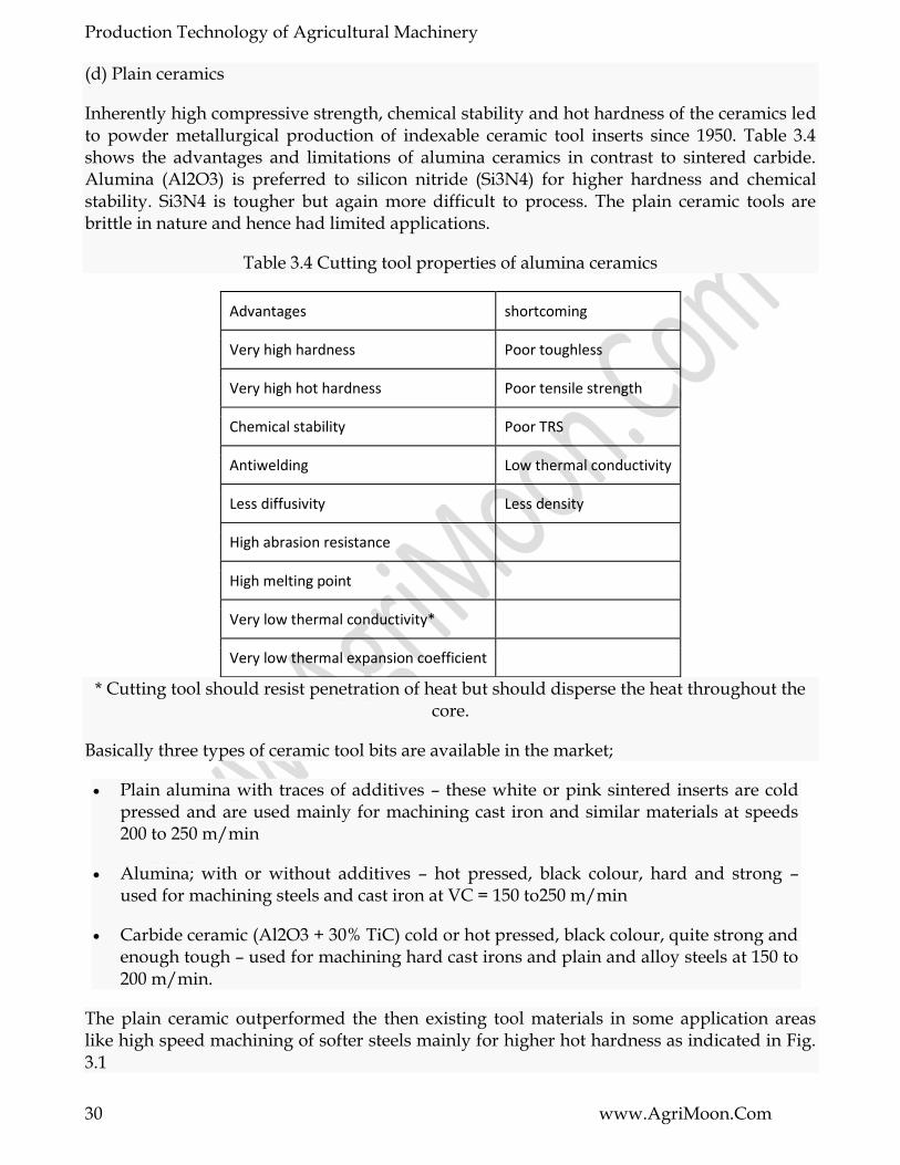
Inherently high compressive strength, chemical stability and hot hardness of the ceramics led to powder metallurgical production of indexable ceramic tool inserts since 1950. Table 3.4 shows the advantages and limitations of alumina ceramics in contrast to sintered carbide. Alumina (Al2O3) is preferred to silicon nitride (Si3N4) for higher hardness and chemical stability. Si3N4 is tougher but again more difficult to process. The plain ceramic tools are brittle in nature and hence had limited applications.
Table 3.4 Cutting tool properties of alumina ceramics
Advantages shortcoming
Very high hardness Poor toughless
Very high hot hardness Poor tensile strength
Chemical stability Poor TRS
Antiwelding Low thermal conductivity
Less diffusivity Less density
High abrasion resistance
High melting point
Very low thermal conductivity*
Very low thermal expansion coefficient
* Cutting tool should resist penetration of heat but should disperse the heat throughout the core.
Basically three types of ceramic tool bits are available in the market;
Plain alumina with traces of additives – these white or pink sintered inserts are cold pressed and are used mainly for machining cast iron and similar materials at speeds 200 to 250 m/min
Alumina; with or without additives – hot pressed, black colour, hard and strong – used for machining steels and cast iron at VC = 150 to250 m/min
Carbide ceramic (Al2O3 + 30% TiC) cold or hot pressed, black colour, quite strong and enough tough – used for machining hard cast irons and plain and alloy steels at 150 to 200 m/min.
The plain ceramic outperformed the then existing tool materials in some application areas like high speed machining of softer steels mainly for higher hot hardness as indicated in Fig. 3.1
Production Technology of Agricultural Machinery
31 www.AgriMoon.Com
However, the use of those brittle plain ceramic tools, until their strength and toughness could be substantially improved since 1970, gradually decreased for being restricted to
uninterrupted machining of soft cast irons and steels only
relatively high cutting velocity but only in a narrow range (200 ~ 300 m/min)
requiring very rigid machine tools
Advent of coated carbide capable of machining cast iron and steels at high velocity made the then ceramics almost obsolete.

Production Technology of Agricultural Machinery
32 www.AgriMoon.Com
LESSON 4. CUTTING TOOLS FOR CNC MACHINES
4.1 Introduction
Cutting tools are available in three basic material types: high-speed steel, tungsten carbide, and ceramic. High-speed steel is generally used on aluminum and other nonferrous alloys, while tungsten carbide is used on high-silicon aluminums, steels, stainless steels, and exotic metals. Ceramic inserts are used on hard steels and exotic metals. Inserted carbide tooling is becoming the preferred tooling for many CNC applications. For the full utilization of CNC machines it is essential to pay due attention to the selection and usage of tooling, namely tool holders, cutting tools and work holding devices. The tools for CNC machines must be quickly changeable to reduce non-cutting time, preset and reset outside the machine, high degree of interchangeability, increased reliability and high rigidity.
4.2 Classification of cutting tools
The cutting tools can be classified on the basis of setting up of tool, tool construction and cutting tool material:
On the Basis of Setting up of Cutting Tool
(a) Preset tools.
(b) Qualified tools.
(c) Semi qualified tools.
On the Basis of Cutting Tool Construction
(a) Solid tools.
(b) Brazed tools.
(c) Inserted bit tools.
On the Basis of Cutting Tool Material
(a) High speed steel (HSS).
(b) High carbon tool steel (HCS).
(c) Cast alloy.
(d) Cemented carbide.
(e) Ceramics.

Production Technology of Agricultural Machinery
33 www.AgriMoon.Com
(f) Boraon Nitride.
(g) Diamond.
(h) Sialon.
4.2.1 Preset Tools
The setting of tools in advance at a place away from the machine tool or offline, in special holders is known as preset tools. A presetting device is used to preset axial and radial positions of the tool tip on the tool holder. Once this is done, the tool holder is ready to be mounted on the machine and produce a known dimension. Presetting devices to various levels of sophistication are available like optical projector. Tool length and tool diameter compensation facilities available in the present day CNC machines have brought down the importance of presetting. Since the generation of actual geometry is taken care of by the CNC part program, which is essentially the coordinates through which the cutting tool tip moves, it is important to know the actual dimensions of the tool when it is placed in the spindle. The relationship of the tool with reference to the tool holding mechanism requires a special attention during CNC machining process. The actual point to be programmed in a CNC part program is the tip of the tool whereas the axes will be moving with respect to a known point in the spindle, e.g. the centre of the spindle in case of machining centres. It becomes therefore necessary to know precisely the deviation of the tool tip from the gauge point on the spindle.
Fig. 4.1 Tool Offset Determination in CNC Machines
4.2.2 Qualified Tools
Tool which fits into a location on the machine, where its cutting edge is accurately positioned within close limits relative to a specified datum on the tool holder or slide, is known as qualified tool. The cutting tools satisfy the following requirements:
(a) Tools need not be measured individually.
(b) No presetting device is used.
(c) The dimensions of the tool holder which are fixed and known.
(d) Set up time is reduced.
(e) Control dimensions of the tool are nominal and fixed.

Production Technology of Agricultural Machinery
34 www.AgriMoon.Com
(f) Higher control on resharpening e.g. drills, reamers.
(g) Cutter for better size control e.g. end mills, teamers.
(h) Chip breaking facilities incorporated in tool.
(i) Impoved designs.
The qualified tool with holder shown in Figure 4.2
Countersink Drill Bit
Fig. 4.2 Qualified Tooling for CNC Machines
4.2.3 Semi-qualified Tools
The qualified tools which can be adjusted to the dimensions by using several adjustable buttons on the tool shank are known as semi qualified tools. These tools demand regular maintenance and calibration for accurate dimensioning.
Fig. 4.3 Semi-qualified Tooling for CNC Machines
4.2.4 Solid Tools
Solid tools are usually made of High Speed Steel or High Carbon Steel. These tools are used on high speeds with sufficient quantity of cutting fluid to get good suface finish and longer tool life.

Production Technology of Agricultural Machinery
35 www.AgriMoon.Com
Fig. 4.4 Solid Tool
4.2.5 Brazed Tools
A forged shank of high strength steel with belt of high speed steel, tungusten carbide stellite brazed to the shank on the cutting edge.
4.2.6 Inserted Bit Tools
The tools with indexible inserts of harder and special grade carbide/ceramic materials. A wear resistant layer of Titanium nitride of Titanium carbide is coated on the insert it reduces the cost of tool. Inserts can be easily removed from the tool holder. So tool changing time and cost of machining are less.
4.2.7 High Speed Steel
The H.S.S. is carbon steel to which alloying elements like tungusten, chromium, vanadium, cobalt and molyblemum to be added to increase their hardness and wear resistance.
4.2.8 High Carbon Tool Steel
High carbon tool steel is suitable for low cutting speeds and low temperatures. The hardness of this tool is determined by the carbon contents.
4.2.9 Cast Alloy
This is a non ferrous alloy and gives high machining performance than that of H.S.Steel. Its hardness and toughness are high at higher temperatures.
4.2.10 Cemented Carbides
It contains 5% carbon, 13% cobalt and 81% tungsten. This tool is widely used in modern costly machines as tip tools. The tool setting time is reduced.
4.2.11 Ceramics
It can be used for higher cutting speed, superior surface finish and great machining flexibility. The Aluminum oxides, boron carbides, silicon carbide, titanium borides and titanium carbides are known as ceramics.
4.2.12 Boron Nitride
(a) High wear resistance.
(b) Used for machining hardened steel and high temperature alloys.
4.2.13 Diamond
(a) Low friction and high wear resistance.
(b) Good cutting edge.
Production Technology of Agricultural Machinery
36 www.AgriMoon.Com
(c) Single crystal diamond is used to machine copper to a high surface finish.
4.2.14 Sialon
Used for machining aerospace alloys.
4.3 Design Features of CNC Tooling
In general the following points are to be considered while designing of CNC tooling:
(a) To give High accuracy.
(b) For variety of operations.
(c) Interchangeability to produce same accuracy.
(d) Flexibility.
(e) Rigidity of tooling to withstand cutting forces.
(f) Rigidity to transmit the power at higher speeds.
(g) Quick changing of tools to keep the down time minimum.
4.4 Work Holding Devices for CNC Machines
In the CNC machines, fixtures are still required to locate and hold the work pieces while machining. The work holding devices should have the following uniqueness:
a) Work holding devices must have required accuracy and must have matching reference surfaces with the reference system.
b) Work holding devices are allowed to perform a number of operations on different faces in a single setting.
c) Work holding devices must enable quick loading and unloading.
d) Work holding devices must be fool-proofing to avoid incorrect loading of the job.
e) Work holding devices must be sufficient rigidity to fully withstand the cutting forces.
f) Work holding devices must be safe in use and loading and unloading.
g) Work holding devices must have a sufficient of clamping force for use of full roughing cuts.
h) Work holding devices must be simple in construction maximum as possible.
Automatic pallet changes over systems are used in modern CNC machines. These pallets simply move for interchanging their positions on the machine table. While machining is being done on a job kept on one pallet, the other pallets are accessible to the operator for

Production Technology of Agricultural Machinery
37 www.AgriMoon.Com
clamping and unclamping raw material or finished product. This saves a lot of material handling and set up time, resulting in higher productivity.
Fig. 4.5 Automatic Pallet Changer
4.5 Automatic Tool Changer
The CNC machines are designed to perform a number of operations in a single setting of the job. A number of tools may be required for making a complex part. In a manual machine, the tools are changed manually whenever required. In a CNC machine, tools are changed through program instructions. The tools are fitted in a tool magazine or drum. When a tool needs to be changed, the drum rotates to an empty position, approaches the old tool and pulls it. Then it again rotates to position the new tool, fits it and then retracts. This is a typical tool changing sequence of an automatic tool changer (ATC).
The concept of the ATC is that the range of tools for a specific job shall be made available for automatic selection and positioning. ATC cab be
Drum Type: For holding small number of tools usually not more than 30, Stored on periphery of drum and tool search speed is faster.
Chain Type: For more number of tools (40 or more), tools search speed is less.
Figure 4.6 Drum Type Automatic Tool Changer (ATC)

Production Technology of Agricultural Machinery
38 www.AgriMoon.Com
Fig. 4.7 Chain Type Automatic Tool Changer (ATC)
As soon as the tool selection command is received by the system, the selected tool comes to a fixed place known as tool change position. The selected tool is transferred to the spindle from magazine after the previous tool is transferred to the magazine from spindle. This is called tool change cycle.
4.5.1 Automatic Tool Changer Advantages
(a) Lines changed in seconds instead of hours.
(b) Increase operator safety by changing tools automatically.
(c) Change tools in seconds for maintenance and repair.
(d) Increase flexibility.
(e) Heavy and large multi-tools that are automatically exchanged.

Production Technology of Agricultural Machinery
39 www.AgriMoon.Com
LESSON 5. CUTTING TOOLS FOR FINISHING OPERATIONS
5.1 Introduction
As the name of this group of abrasive operations suggests, their objective is to achieve superior surface finish up to mirror-like finishing and very close dimensional precision. The finishing operations are assigned as the last operations in the single part production cycle usually after the conventional or abrasive machining operations, but also after net shape processes such as powder metallurgy, cold flashless forging, etc.
The finishing processes discussed in this section include honing, lapping, superfinishing, polishing, and buffing. The typical surface finishes for these operations are presented in the fig.1. Also presented for comparison are surface roughness values for fine grit size grinding.
Fig. 5.1 Typical surface finishing operations
5.2 Honing
Honing is a finishing process performed by a honing tool, which contains a set of three to a dozen and more bonded abrasive sticks. The sticks are equally spaced about the periphery of the honing tool. They are held against the work surface with controlled light pressure, usually exercised by small springs. The honing tool is given a complex rotational and oscillatory axial motion, which combine to produce a crosshatched lay pattern of very low surface roughness:
Fig. 5.2 Schematics of honing process showing the honing tool

Production Technology of Agricultural Machinery
40 www.AgriMoon.Com
In addition to the surface finish of about 0.1 µm, honing produces a characteristic crosshatched surface that tends to retain lubrication during operation of the component, thus contributing to its function and service life. A cutting fluid must be used in honing to cool and lubricate the tool and to help remove the chips.
A common application of honing is to finish the holes. Typical examples include bores of internal combustion engines, bearings, hydraulic cylinders, and gun barrels.
5.3 Lapping
In lapping, instead of a bonded abrasive tool, oil-based fluid suspension of very small free abrasive grains (aluminum oxide and silicon carbide, with typical grit sizes between 300 and 600) called a lapping compound is applied between the workpiece and the lapping tool.
The lapping tool is called a lap, which is made of soft materials like copper, lead or wood. The lap has the reverse of the desired shape of the workpart. To accomplish the process, the lap is pressed against the work and moved back and forth over the surface in a figure-eight or other motion pattern, subjecting all portions of the surface to the same action. Lapping is sometimes performed by hand, but lapping machines accomplish the process with greater consistency and efficiency.
Fig. 5.3 Schematics of lapping process
The cutting mechanism in lapping is that the abrasives become embedded in the lap surface, and the cutting action is very similar to grinding, but a concurrent cutting action of the free abrasive particles in the fluid cannot be excluded.
Lapping is used to produce optical lenses, metallic bearing surfaces, gages, and other parts requiring very good finishes and extreme accuracy.
5.4 Superfinishing
Superfinishing is a finishing operation similar to honing, but it involves the use of a single abrasive stick. The reciprocating motion of the stick is performed at higher frequency and smaller amplitudes. Also, the grit size and pressures applied on the abrasive stick are smaller. A cutting fluid is used to cool the work surface and wash away chips.

Production Technology of Agricultural Machinery
41 www.AgriMoon.Com
Fig. 5.4 Schematics of the superfinishig process
In superfinishing, the cutting action terminates by itself when a lubricant film is built up between the tool and work surface. Thus, superfinishing is capable only of improving the surface finish but not dimensional accuracy. The result of these operating conditions is mirror like finishes with surface roughness values around 0.01 µm. Superfinishing can be used to finish flat and external cylindrical surfaces.
5.5 Polishing and buffing
Polishing is a finishing operation to improve the surface finish by means of a polishing wheel made of fabrics or leather and rotating at high speed. The abrasive grains are glued to the outside periphery of the polishing wheel. Polishing operations are often accomplished manually.
Buffing is a finishing operation similar to polishing, in which abrasive grains are not glued to the wheel but are contained in a buffing compound that is pressed into the outside surface of the buffing wheel while it rotates. As in polishing, the abrasive particles must be periodically replenished. As in polishing, buffing is usually done manually, although machines have been designed to perform the process automatically.
Fig. 5.5 Schematics of the buffing operation.
Polishing is used to remove scratches and burrs and to smooth rough surfaces while buffing is used to provide attractive surfaces with high luster.

Production Technology of Agricultural Machinery
42 www.AgriMoon.Com
MODULE 3. Advanced manufacturing techniques
LESSON 6. ADVANCED MANUFACTURING TECHNIQUES
1.1. Introduction
Manufacturing covers wide areas of inputs, processes and products. It reaches out to the demands in production for thousands of different varieties and types of goods. These demands range from large ships to hand drilling equipment, and from micro circuits to automobiles. The number and complexity of processes involved in the production of these goods varies drastically. The extent of alterations involved in these processes form the very basis for getting a bird‘s eye view of the manufacturing activity. Some are simple primary product and some are simply transformed products such as basic metallic shapes, paint and utensils. The next are moderately transformed products such as wires, rods, metal pipes and tubes, while others are elaborately transformed products such as prefabricated metal shapes, wire products, glassware and ceramic products. The mechanization and extent to which it is involved in the process of production gives another view of manufacturing. Manufacturing covers a very wide range of situations right from robot controlled highly mechanized lines of production to some simple day to day use equipments with mechanical activities.
Thus, manufacturing industries, today, encompasses a dimension scale of more than fifteen orders of magnitudes. The design and manufacture of huge machinery, ship and spacecrafts on one side while nano and pico technology on the other side of the dimension scale, highlights the challenges ahead for engineers and technologists. With the advancement of technology newer materials, energy sources, manufacturing technology, decision-making and management techniques are being developed. These unfold lot of opportunities for the scientific and academic fraternity. At the same time, newer challenges in the form of environmental and other issues put stringent requirements on the technology. Global competition, the thrust on quality and demand for higher productivity are some of the challenges before the present industrial and manufacturing units. To survive and to succeed further, the competitors have a unique option, which is understanding of the dynamic changes that are taking place in the business environment. In view of the above, a nation should develop and update its infrastructure, such that the new and advanced technology gets into hand in hand, with the ongoing time.
1.2. Manufacturing
There are many ways and definitions available to explain the concept of manufacturing. Some of these definitions are listed below:
1. The process of converting raw materials into finished products.
2. Manufacturing is a very broad activity, encompassing many functions – everything from purchasing to quality control of the final product.

Production Technology of Agricultural Machinery
43 www.AgriMoon.Com
3. Chemical or Physical transformation of the materials, substances or components into some new products
4. Manufacturing is a value addition activity to the raw materials, substances/components.
5. Manufacturing is a process through which products are made through various production activities.
6. Manufacturing is the use of machines, tools and labor to make things for use or sale.
7. Manufacturing is an application of different resources such as machinery and people used for converting the materials into finished goods.
1.3. Manufacturing system
In order to consider manufacturing, as a system, we need to look beyond the conversion of raw material and processes which lead to finished products. The understanding of the manufacturing system as a whole helps in identifying which process parameters and functions of the organizations that are important. This helps to make decisions about the economical ways of producing the end products. There are several factors which are usually considered in taking a final and relevant decision about the best way of producing the desired end product. A manufacturing system can be considered as a simple input-output system at the first stage as shown in Fig. 1.1
Fig. 1.1.Input-output system
The input-output model does not provide the sufficient information about the all aspects of manufacturing. Manufacturing involves more than just processing of raw materials. The overall manufacturing system starts from the market or specifically from the customer requirements and ends when the product reaches the hands of customers. The present day trends also look beyond the delivery of the product to the customer i.e. after sale, services offered by the organization. The basic model at Fig..1.2 is further expanded to incorporate most of the functions involved in an organization for the design, planning and manufacturing of a product. The manufacturing system incorporating all the above aspects (holistic approach) as shown in Fig.1.2

Production Technology of Agricultural Machinery
44 www.AgriMoon.Com
Fig. 1.2 Manufacturing system boundary
1.4. Manufacturing trends
In 1960s, the success of a manufacturing company depended on cost. In 1980s, the success of a manufacturing company depended on quality. Present day, the success of manufacturing company depends on cost, quality and lead
time (lead time is time between placing the order and receiving it, alternatively, it is also known as time to market)
1.5. Manufacturing challenges
The emerging economies, the social and political transitions taking place and the new ways of doing business are changing the world dramatically. It is visualized through these trends that manufacturing environment of the future would be extremely competitive and significantly different from what it is today. In-order to remain successful in such an environment, the manufacturers needs to be updated with the latest trends and should possess dynamic capabilities, which need to be distinctly different. The main challenge for the future entrepreneurs is the attainment of such capabilities, some of which are as discussed below:
The ability to innovative ideas and to develop a creative environment for such innovations in manufacturing

Production Technology of Agricultural Machinery
45 www.AgriMoon.Com
Development of effective and efficient training and education programs for the manufacturing workforce, as more skilled workforce is required
The use and implementation of information technology in various areas of the manufacturing industries and their sub-functions
Sustainability of small and medium scale enterprises to provide support to the large scale manufacturing organizations
Focusing on clean and green manufacturing technologies, the environment and the society issues. The responsibility for the production process thus goes hand-in-hand with responsibility for the final disposal of products i.e. recycling in line with environmental policies.
1.6. Need of advance manufacturing technology
Manufacturing is the basis for all economic activities and future growth of a country
At the beginning of 20th century, mass production using efficient machine tools emerged in USA (Ford motors)
After the second world war, new / advanced manufacturing processes came into existence
Since 1950s, new technologies have been emerged – computerized numerical control, flexible manufacturing systems, lean manufacturing, green manufacturing, computer integrated manufacturing are some of those.
Newer materials have been developed and their processing requires special machine tools or special manufacturing process
Therefore, there is a vital need to have more efforts to continuously advance manufacturing technology for a better-off and more stable future
1.7. Manufacturing processes classification
There are six basic / fundamental classifications of manufacturing processes.
1. Metal casting or Molding: expendable mold and permanent mold
2. Metal Forming and Shearing: rolling, forging, extrusion, drawing, sheet forming, powder metallurgy
3. Material Removal Processes / Machining Processes: turning, boring, drilling, milling, planing, shaping, broaching, grinding, ultrasonic machining, chemical machining, electrical discharge machining (EDM), Abrasive flow machining (AFM), abrasive jet machining (AJM), electrochemical machining, high-energy beam machining, laser beam machining (LBM) etc.

Production Technology of Agricultural Machinery
46 www.AgriMoon.Com
4. Joining: welding, brazing, soldering, diffusion bonding, adhesive bonding, mechanical joining, plasma arc, plasma MIG, projection welding, ultrasonic, electron beam welding, laser welding etc.
5. Finishing (painting, anti-corrosion coatings, etc.)
6. Rapid Manufacturing: stereo-lithography, selective laser sintering, fused deposition modeling, three dimensional printing, laminated object manufacturing, laser engineered net shaping
1.8. Material removal processes / Machining (Subtractive processes)
Metal removal processes, in which we remove the excess material to give the final shape to the product, are often termed as secondary or machining processes. They are also termed as finishing processes; which are done to give the required finish or tolerance to the end product. This means that in both the cases i.e. either removal of material or finishing of part, the product to be cut or finished is made by one of the other processes described above. At instances, the product geometry is very complex, to be produced by other processes. In such cases the basic shape of the product is produced using other processes and the final shape is created by using some machining process. The major metal removal / machining processes are as given below:
Milling, Turning, Drilling
Broaching, Shaping, Planning
Honing, Etching, Grinding
Finishing Processes
Abrasive Flow Machining
Abrasive Jet Machining
Water Jet Machining
Electro Discharge Machining (EDM)
Wire Cut EDM
Electro Chemical Machining (ECM)
Electron Beam Machining (EBM)Ultrasonic Machining/Drilling (USM / USD)
Laser Beam Machining (LBM)
Electro Chemical Grinding (ECG)
Hybrid Processes

Production Technology of Agricultural Machinery
47 www.AgriMoon.Com
LESSON 7. ELECTRICAL DISCHARGE MACHINING (EDM)
2.1. Introduction
It is an advanced machining process primarily used for hard and difficult metals which are difficult to machine with the traditional techniques. Only electrically conducting materials are machined by this process. The EDM process is best suited for making intricate cavities and contours which would be difficult to produce with normal machines like grinders, end-mills or other cutting tools. Metals such as hardened tool-steels, carbides, titanium, inconel and kovar are easily machined through EDM.
EDM is a thermal process which makes use of spark discharges to erode the material from work piece surface. The cavity formed in EDM is a replica of the tool shape used as the erosions occur in the confined area. Since spark discharges occur in EDM, it is also called as "spark machining". The material removal takes place in EDM through a rapid series of electrical discharges. These discharges pass between the electrode and the work piece being machined. The fine chips of material removed from the work piece gets flushed away by the continuous flowing di-electric fluid. The repetitive discharge creates a set of successively deeper craters in the work piece until the final shape is produced.
2.2. EDM Principle
The schematic of the basic EDM process is illustrated in Fig. 3.2.1. In this process, the work piece and tool are submerged into a non-conducting, dielectric fluid which is separated by a small gap (for sparking). The dielectric fluid insulates the work piece from the tool and creates the resistance of electricity flow between the electrodes. The dielectric fluid may be typical hydrocarbon oil (kerosene oil) or de-ionized water. It also helps in cooling down the tool and workpiece, clears the inter-electrode gap (IEG), and concentrates the spark energy to a small cross sectional area under the electrode.

Production Technology of Agricultural Machinery
48 www.AgriMoon.Com
Fig. 3.2.1.Schematic of electric discharge machining
As the two electrodes come closer to one another, the electric field intensity increases beyond the strength of the dielectric enabling it to break and thereby allow the current to flow between the two electrodes. As a result of this effect, intense heat gets generated near the zone, which melts and evaporates the material in the sparking zone. As the flow of current is momentarily stopped, some fresh dielectric liquid particles come in position between the inter-electrode gap which restores the insulating properties of the dielectric. The solid particles (debris) are carried away by the flowing dielectric. Flushing refers to the addition of new liquid dielectric to the inter-electrode volume. A close view of the EDM process is shown in Fig. 3.2.2. The sparks occur at spots where the tool and the workpiece surfaces are the closest and since the spots change after each spark (because of the material removal after each spark), the spark travels all over the surfaces. This results in uniform removal of material, hence exact shape get reproduced on the workpiece surface.
Fig. 3.2.2 Close view of EDM region
2.3. Advantages of EDM
The major advantages of the process are:
Any materials that are electrically conductive can be machined by EDM.
Materials, regardless of their hardness, strength, toughness and microstructure can be easily machined / cut by EDM process
The tool (electrode) and workpiece are free from cutting forces
Edge machining and sharp corners are possible in EDM process
The tool making is easier as it can be made from softer and easily formable materials like copper, brass and graphite.
The process produces good surface finish, accuracy and repeatability.

Production Technology of Agricultural Machinery
49 www.AgriMoon.Com
Hardened work-pieces can also be machined since the deformation caused by it does not affect the final dimensions.
EDM is a burr free process.
Hard die materials with complicated shapes can be easily finished with good surface finish and accuracy through EDM process.
Due to the presence of dielectric fluid, there is very little heating of the bulk material.
2.4. Limitations of EDM
Material removal rates are low, making the process economical only for very hard and difficult to machine materials.
Re-cast layers and microcracks are inherent features of the EDM process, thereby making the surface quality poor.
The EDM process is not suitable for non-conductors.
Rapid electrode wear makes the process more costly.
The surfaces produced by EDM generally have a matt type appearance, requiring further polishing to attain a glossy finish.
2.5. Applications of EDM
Hardened steel dies, stamping tools, wire drawing and extrusion dies, header dies, forging dies, intricate mould cavities and such parts are made by the EDM process.
The process is widely used for machining of exotic materials that are used in aerospace and automatic industries.
Deep cavities, slots and ribs can be easily made by EDM as the cutting forces are less and longer electrodes can be used to make such collets, jet engine blade slots, mould
cooling slots etc.EDM being a non-contact type of machining process, it is very well suited for making fragile parts which cannot take the stress of machining. The parts that fit such profiles include washing machine agitators; electronic components, printer parts and difficult to machine features such as the honeycomb shapes.
Micro-EDM process can successfully produce micro-pins, micro-nozzles and micro-cavities.
2.6. Mechanism of Material Removal in EDM
In EDM, for a particular machining condition there are numerous phenomena involved, i.e., heat conduction and radiation, phase changes, electrical forces, bubble formation and collapse, rapid solidification etc. Thermo-electric phenomenon is the most appropriate theory for the explanation of the electrical discharge machining process. The removal of material in EDM is associated with the erosive effects produced when discrete and spatial discharge

Production Technology of Agricultural Machinery
50 www.AgriMoon.Com
occurs between the tool and workpiece electrodes. Short duration sparks are generated between these two electrodes. The generator releases electrical energy, which is responsible for melting a small quantity of material from both the electrodes. At the end of the pulse duration, a pause time begins. The forces that may be of electric, hydrodynamic and thermodynamic in nature remove the melted pools. The material removal process by a single spark is as follows:
An intense electric field develops in the gap between electrode and workpiece.
There are some contaminants inside the dielectric fluid which build a high-conductivity bridge between the electrode and workpiece.
When the voltage increases, the bridge and dielectric fluid between the electrode and workpiece heat up. The dielectric is ionized to form a spark channel. The temperature and pressure rapidly increase and a spark is generated. A small amount of material is evaporated on the electrode and workpiece at the spark contact point.
Bubbles rapidly expand and explode during sparking until the voltage is turned off. Next the heating channel collapses and the dielectric fluid enters into the gap in-order to flush away the molten metal particles.
The material removal rate depends on the following factors:
Peak amperage or intensity of the spark
Length of the ON time
OFF time influences the speed and stability
Duty cycle: percentage of on-time relative to total cycle time
Gap distance: Smaller the gap better is the accuracy and slower is the material removal rate.
The material removal phenomena in EDM are shown schematically in the Fig. 3.2.3

Production Technology of Agricultural Machinery
51 www.AgriMoon.Com
2.7. Types of EDM Processes
1. Die Sinker EDM
2. Wire Cut EDM
2.7.1. Die-Sinker EDM and its Systems
Die-Sinker EDM is known by different names such as Ram EDM, sinker EDM, vertical EDM and plunge EDM. The process is generally used for producing blind cavities. In die-sinker EDM, the electrode and workpiece are submerged in an insulating liquid such as oil or other dielectric fluids. The electrode and workpiece are connected to a suitable power supply. An electrical potential is generated between the tool and the workpiece through the power supply. As the electrode approaches workpiece, the dielectric break down starts taking place in the fluid. Due to this activity, a plasma channel starts forming and sparks jump from the electrode to the workpiece leading to material removal from the workpiece. The principle of die-sinking EDM is shown in Fig. 3.2.4 and the schematic of die-sinker EDM process is shown in Fig. 3.2.5.
The main components of Die-sinker EDM are:
Power supply.
Dielectric system.
Electrode
Servo system.

Production Technology of Agricultural Machinery
52 www.AgriMoon.Com
Power Supply
The power supply provides a series of DC electrical discharges and controls:
Current
Pulse voltage
Pulse duration
Duty cycle
Electrode polarity
Pulse frequency
Dielectric and its Circulation System
The dielectric fluids used in EDM operations are of different types. The most popular dielectric fluids are hydrocarbon oil (kerosene in particular). The other fluids used are transformer oil, paraffin oil; silicon based oil, or de-ionized water. The selection of an appropriate dielectric fluid depends upon its various chemical and fluidic properties (such as flash point, dielectric strength, viscosity, specific gravity and color) The dielectric system performs the following tasks:
It induces clean dielectric into the cutting zone Flushes away debris Cools the workpiece and electrodes

Production Technology of Agricultural Machinery
53 www.AgriMoon.Com
In order to provide circulation of the dielectric fluid to the work piece, the EDM machine tool is equipped with a well-designed dielectric circulation system. It consists of following two parts:
1. Pump : Its main purpose is to circulate the dielectric fluid on-to the workpiece
2. Filter and suction unit: This unit filters out the material debris and any other foreign parts from the dielectric.
Servo System
The servo system is commanded by signals from gap voltage sensor system in the power supply and it controls the in-feed of the electrode to precisely match the required rate of material removal. At times stepper motor can be used instead of a servomotor. As soon as the gap voltage sensor system determines bridging of some pieces of electrically conductive materials between the electrode and work-piece, the servo system immediately reacts and reverses the direction. The process is restored when the gap is flushed by the dielectric fluid. When the gap becomes clear, the in-feed resumes and cutting process continues.
Electrodes
The electrodes for EDM process are usually made of brass, copper, graphite and copper-tungsten alloys.
Design considerations for EDM process
In EDM process, fine openings and deeper slots need to be avoided.
Very fine surface finish values should not be specified.
As the MRR of EDM process is low, the rough cutting should be done by some other machining process and EDM machine should me made used for the finishing operations only.
2.7.2. Wire Cut Electric Discharge Machining (WEDM)
The Wire Electric Discharge Machining (WEDM) is a variation of EDM and is commonly known as wire-cut EDM or wire cutting. In this process, a thin metallic wire is fed on-to the workpiece, which is submerged in a tank of dielectric fluid such as de-ionized water. This process can also cut plates as thick as 300mm and is used for making punches, tools and dies from hard metals that are difficult to machine with other methods. The wire, which is constantly fed from a spool, is held between upper and lower diamond guides. The guides are usually CNC-controlled and move in the x–y plane. On most machines, the upper guide can move independently in the z–u–v axis, giving it a flexibility to cut tapered and transitioning shapes (example: square at the bottom and circle on the top). The upper guide

Production Technology of Agricultural Machinery
54 www.AgriMoon.Com
can control axis movements in x–y–u–v–i–j–k–l–. This helps in programming the wire-cut EDM, for cutting very intricate and delicate shapes.
In the wire-cut EDM process, water is commonly used as the dielectric fluid. Filters and de-ionizing units are used for controlling the resistivity and other electrical properties. Wires made of brass are generally preferred. The water helps in flushing away the debris from the cutting zone. The flushing also helps to determine the feed rates to be given for different thickness of the materials. The schematic of wire cut EDM is shown in Figure 3.2.6.
The WEDM process requires lesser cutting forces in material removal; hence it is generally used when lower residual stresses in the workpiece are desired. If the energy/power per pulse is relatively low (as in finishing operations), little changes in the mechanical properties of the material are expected due to these low residual stresses. The materials which are not stress-relieved earlier can get distorted in the machining process. The selection of process parameters is very crucial, as in some cases the workpiece undergoes significant thermal cycles that can be very severe. These thermal cycles can form recast layers and induce residual tensile stresses on the workpiece which are undesired.
Process of Material Removal in Wire-Cut EDM
In the WEDM process, the motion of wire is slow. It is fed in the programmed path and material is cut/ removed from the workpiece accordingly. Electrically conductive materials are cut by the WEDM process by the electro-thermal mechanisms. Material removal takes place by a series of discrete discharges between the wire electrode and workpiece in the presence of a di-electric fluid. The di-electric fluid gets ionized in between the tool-electrode gap thereby creating a path for each discharge. The area wherein discharge takes place gets heated to very high temperatures such that the surface gets melted and removed. The cut particles (debris) get flushed away by the continuously flowing dielectric fluid.
WEDM is a non-conventional process and is very widely used in tool steels for pattern and die making industries. The process is also used for cutting intricate shapes in components used for the electric and aerospace industries.
Applications of Wire-Cut EDM

Production Technology of Agricultural Machinery
55 www.AgriMoon.Com
Wire EDM is used for cutting aluminium, brass, copper, carbides, graphite, steels and titanium. The wire material varies with the application requirements. Example: for quicker cutting action, zinc-coated brass wires are used while for more accurate applications, molybdenum wires are used.
The process is used in the following areas:
Aerospace, Medical, Electronics and Semiconductor applications
Tool & Die making industries.
For cutting the hard Extrusion Dies
In making Fixtures, Gauges & Cams
Cutting of Gears, Strippers, Punches and Dies
Manufacturing hard Electrodes.
Manufacturing micro-tooling for Micro-EDM, Micro-USM and such other micro-machining applications.

Production Technology of Agricultural Machinery
56 www.AgriMoon.Com
LESSON 8. POWDER METALLURGY
3.1. Introduction
Powder metallurgy is the art and science of producing fine metal powders and then making objects from individual, mixed or alloyed metal powders with or without the inclusion of non metallic constituents. (Or) Powder metallurgy is a branch of metallurgy which deals with the production of metal and non metal powders and subsequently manufacture of components by using these powders.
3.2. Powder Metallurgy Process
1. Producing metal powders
2. Mixing
3. Pressing
4. Presintering
5. Sintering
6. Finishing and sizing the final product.
Fig. 3.3.1. Flow chart of powder metallurgy process

Production Technology of Agricultural Machinery
57 www.AgriMoon.Com
3.2.1.Producing metal powders
Various methods for manufacturing powders are
i. Atomization
ii. Reduction
iii. Crushing
iv. Milling
v. Shotting
vi. Electrolysis.
Atomization
The process of metal spraying against a stream of compressed air or inert gas is atomization. It is an excellent means of producing metal powders from many of the low temperature metals such as lead, aluminum, zinc and tin.
Fig. 3.3.2 Atomization
Reduction
Reduction process is carried out in an atmosphere controlled furnace.In reduction process, the compounds of metals usually oxides like iron oxides are reduced with CO/H at temperature below melting point of metal. Tungsten, molybdenum, iron, cobalt, nickel powders are commercially produced by this process.
Fig. 3.3.3. Reduction

Production Technology of Agricultural Machinery
58 www.AgriMoon.Com
Crushing
Process of passing the metal powders against two rollers so that the metal powders are crushed to required size. Crushing requires equipments such as stamp, hammers, and jaw crushers.
Fig. 3.3.4 Crushing
Milling
Milling is carried out by using equipments such as ball mill, rod mill, impact mill, disk mill etc. In ball milling, material to be powdered is collected in a container with a large number of hard steel balls. These balls hit the material and break it in powder form.
Shotting
The process of pouring molten metal through a sieve or orifice and cooling by dropping into water is known as shotting. This process gives spherical or pear shaped powder particles.
Electrolysis
In this method, an electrolytic cell is set up as shown in figure. The desired metal is made to act as anode. Anode slowly dissolves and gets deposited on the cathode from where the deposit is removed, washed and dried.
Fig. 3.3.5 Electrolysis

Production Technology of Agricultural Machinery
59 www.AgriMoon.Com
3.2.2 Mixing / blending of metal powders
Blending : Mixing powder of the same chemical composition but different sizes
Mixing : Combining powders of different chemistries
The above figure (a) shows the container in which the powder to be mixed is added
The blade continuously rotates and mixes the powder.
Figure (b) shows a rotating drum in which powder is filled and the drum keeps on rotating and simultaneously mixing the powders.
Wet or dry mixing is generally employed.
For wet mixing water or dry solvent is used to obtain better mixing.
Blending and mixing is necessary for Addition of lubricants coats the powders and reduces die wear and
lowers pressure required for pressing of powders. Mixing powders of different materials
Obtaining uniform distribution of particle sizes.
3.2.3 Compacting / Pressing of metal powders.
Pressing the powders into desired part shape as closely as possible to final dimensions
Powders are compacted using high pressure.
Degree of pressure required depends upon Required density of final product
Ease with which powder particles will weld together.
Compacting processes are i. Die pressing
ii. Roll pressing
iii. Extrusion
Die pressing
➢It consists of upper punch and lower punch as shown in fig.
➢Powder is filled on the space above lower punch.
➢Upper punch applies high pressure to the powder.
➢Finally the green compact powder is received as shown in fig.

Production Technology of Agricultural Machinery
60 www.AgriMoon.Com
Fig. 3.3.6 Die pressing
Roll pressing
➢ Two rolls of appropriate sizes are used.
➢Stream of powder is guided, so that the rolls are able to apply the necessary compacting pressure in a continuous sequence.
Fig. 3.3.7 Roll pressing
Extrusion method
➢Ram is used for applying force.
➢ Two dies are used for achieving proper thickness.
➢As seen in the figure the green compact is received which is further send for sintering process.

Production Technology of Agricultural Machinery
61 www.AgriMoon.Com
Fig. 3.3.8 Extrusion
3.2.4 Presintering
Powder metallurgy is used to make parts from materials that are very difficult to machine.
When some machining is required on such parts, Presintering is done before actual sintering operation.
Compact is heated for a short time at a temperature below sintering temperature
Presintering removes lubricants and binders added to powders during blending operation.
After presintering, the part acquires sufficient strength to be handled and machined without difficulty
3.2.5. Sintering
Sintering is the heat treatment process, to bond the metallic particles, thereby increasing strength and hardness
Sintering consists of heating pressed metal compacts in batch or continuous furnaces to a temperature below the melting point of material.
Most metals are sintered at 70 % to 80 % of melting temperature.
Fig. 3.3.9 Sintering

Production Technology of Agricultural Machinery
62 www.AgriMoon.Com
3.3. Secondary /Finishing Operations
A number of secondary and finishing operations can be applied after sintering, some of them are:
Sizing : cold pressing the sintered part to improve dimensional accuracy.
Coining : cold pressing to press details into its surface.
Impregnation : oil fills the pores of the part
Infiltration : pores are filled with a molten metal
Heat treating : annealing can be done for stress relief in powder metallurgy part.
Machining : creates geometric features that cannot be achieved by pressing, such as threads, side holes, and other details
3.4 Characteristics of metal powders / powder testing
A powder can be defined as a finely divided particulate solid.
Engineering powders include metals and ceramics.
The main purpose of powder testing is to ensure whether or not the powder is suitable for further processing.
Principle characteristics of metal powders are
1. Chemical composition (purity)
2. Particle size and its distribution
3. Particle shape
4. Particle porosity
5. Particle microstructure
6. Specific characteristics like -Specific surface, apparent density, tap density, flow rate, green density and green strength
Chemical composition (Purity)
It is the term to understand the type and percentage of impurities that the powder contains.

Production Technology of Agricultural Machinery
63 www.AgriMoon.Com
Fig. 3.3.10. Several of the possible (ideal) particle shapes in powder metallurgy
Particle size and its distribution
The particle size is defined by the mesh count. Mesh count refers to the number of openings per linear inch of mesh.
Particle shape
Various shapes of metal powders observed according to the method of production
Particle porosity
•Ratio of the volume of the pores (empty spaces) in the powder to the bulk volume
•Porosity increases stress in the part so it is not desirable.
Particle microstructure
•For observation of microstructure, the powder metallurgy part is first polished, then etching of the surface similar to the dye penetrant method is done which will show the microstructure of the powder metallurgy part.

Production Technology of Agricultural Machinery
64 www.AgriMoon.Com
Fig. 3.3.11 micro structure of particles
3.5. Specific characteristics
Specific surface: Total surface area of particle per unit weight.
Apparent density: It is also called packing density – mass per unit volume of loose powder or unpacked powder.
Tap density: Density of powder after it is packed.
Flow rate: Rate with which metal powder flows under gravity from container.
Green density: Density of compacted powder before sintering
Green strength: Strength of metal powder before it is sintered (heated).
Green spring: After the ejection of compacted powder from die, expansion of powder takes place. The difference between size of compact and die is green spring.
3.6. Advantages of powder metallurgy process
A combination of metals and non metals powdered parts can be manufactured.
High dimensional accuracy is achieved.
Fine surface finish is achieved.
No material is wasted as scrap. This process makes use of 100 % raw material unlike casting, press forming etc.
Porous parts can be produced which is not possible by any other method.
Highly qualified or skilled person is not required for handling powder metallurgy method.
Large scale production of small parts with this process gives efficient results.
Production of cemented carbide tools is possible only by this process.
It eliminates numerous machining operations.

Production Technology of Agricultural Machinery
65 www.AgriMoon.Com
Powder metallurgy parts can be easily brazed, welded, soldered.
Process is economical as mass production process.
3.7. Limitations of powder metallurgy process
There are limitations and disadvantages associated with P/M processing. These include:
High tooling costs.
Expensive raw materials (powders).
Relatively long parts are difficult to manufacture.
Difficult storing and handling of powders
Powder metallurgy is not economical for small scale production.
Articles produced by powder metallurgy process possess poor ductility.
Difficult to produce high purity powder.
Due to porosity, specified mechanical properties are difficult to be obtained.
P/M parts show poor plastic properties.
Punches, dies, rolls etc are very costly and also very bulky to transfer from one place to another

Production Technology of Agricultural Machinery
66 www.AgriMoon.Com
MODULE 4. Heat treatment of steel
LESSON 9. HEAT TREATMENT OF STEEL
1.1 Introduction
Heat treatment is a method used to alter the physical, and sometimes chemical, properties of a material. Heat treatment involves the use of heating or chilling, normally to extreme temperatures, to achieve a desired result such as hardening or softening of a material. Or Heat treatment is the controlled heating and cooling of metals to alter their physical and mechanical properties without changing the product shape.
Heat treatment is defined as an operation or combination of heating and cooling of a metal or alloy in the solid state for the purpose of obtaining desired change in properties. The heat treatment includes
Heating the metal to pre determined temperature
Holding the metal at that temp until the structure becomes uniform throughout the mass.
Cooling at pre determined rate to cause formation of desired change.
1.2 Objectives
To increase the hardness of metals
To relieve internal stress
To improve machinability
To improve mechanical properties like tensile strength, ductility and shock resistance
To change in grain size
To increase resistance to heat and corrosion
To modify electrical and magnetic properties
To change in chemical composition of metal surface
To remove gases

Production Technology of Agricultural Machinery
67 www.AgriMoon.Com
1.3 Types of heat treatment processes
1. Annealing
2. Normalizing
3. Hardening
4. Tempering
5. Case hardening
i. Carburizing
ii. Cyaniding
iii. Nitriding
6. Surface hardening
i. Induction hardening
ii. Flame hardening
7. Diffusion coating
1.3.1 Annealing
The process consists of slow heating the steel slightly above (30-50oC) the critical point (AC3) for hypo eutectoid (GS) and the same amount above PSK for the hyper eutectoid holding it at this temp for considerable period (3.4 min/mm length of piece); slow cooling in sand (the rate of cooling from 30oC to 200oC depends upon the composition of the steel. The grain structure has coarse Pearlite with ferrite or Cementite (depending on whether hypo or hyper eutectoid). The steel becomes soft and ductile.
Austenite - Pearlite and Ferrite (Hypo eutectoid)
- Pearlite (Eutectoid)
- Pearlite + Cementite (Hyper eutectoid)

Production Technology of Agricultural Machinery
68 www.AgriMoon.Com
Fig. 4.1.1 Temperature ranges for various heat treatment process
The purpose of annealing may involve one or more of the following aims:
To soften the steel and to improve machinability.
To relieve internal stresses induced by some previous treatment (rolling, forging, uneven cooling).
To remove coarseness of grain.
To refine the grain size and structure to improve strength and ductility.
To alter electrical and magnetic properties.
1.3.2 Normalizing
It consists of heating the metal to a temperature just above the critical point (40-50oC) above AC3 line GS and ACm (GSE) within the normalizing range, holding it at this temp for period of 15 min and cooling in still air to room temperature. This process provides a homogeneous structure consisting of ferrite and pearlite for hypo eutectoid steels and pearlite and cementite for hyper eutectoid steels. This is done,
To produce a harder and stronger steel than full annealing
To refine the grain structure of steel to improve the machinability and tensile strength.
To modify and refine the grain structure
To obtain a relatively good ductility without reducing the hardness and strength

Production Technology of Agricultural Machinery
69 www.AgriMoon.Com
Fig. 4.1.2 Normalizing process
Hardness is a function of the carbon content of the steel. Hardening of a steel requires a change in structure from the body-centered cubic structure found at room temperature to the face-centered cubic structure found in the austenitic region. The steel is heated to autenitic region. When suddenly quenched, the martensite is formed. This is a very strong and brittle structure. When slowly quenched it would form austenite and pearlite which is a partly hard and partly soft structure. When the cooling rate is extremely slow then it would be mostly pearlite which is extremely soft.
Fig.4.1.3 Structure of steel when heated to critical stage
1.3.3 Hardening
It consists of heating the steel to a temperature above the critical point (30-50oC) above AC3 line; holding it at this temperature for a considerable period; quenching (sudden cooling) in water, oil/molten salt solution. The heating operation is required form the purpose of transforming the ferrite and pearlite for hypo eutectoid steels and pearlite and cementite for hyper eutectoid steels into austenite. A rapid cooling form the hardened temperature causes austenite to be transformed into martensite which is very hard and brittle.

Production Technology of Agricultural Machinery
70 www.AgriMoon.Com
Fig.4.1.4. Hardening process
This is done to develop hardness to resist wear and to improve strength, elasticity, ductility and toughness and to enable it to cut other metals (to make it suitable for cutting tools).
1.3.4 Tempering
The steel hardened by rapid quenching is very hard and brittle. It also contains internal stresses, which are severe and unequally distributed to cause cracks or even rupture of hardened steel. Tempering is a process done subsequent to quench hardening. Quench-hardened parts are often too brittle. This brittleness is caused by a predominance of martensite. This brittleness is removed by tempering. Tempering results in a desired combination of hardness, ductility, toughness, strength, and structural stability. It consists of reheating the steel after hardening to a temperature below the critical point (PSK line); holding it for a considerable period and slow cooling (4-5 min/ mm). This is done to reduce the brittleness of the hardened steel and thus to increase ductility. to relieve the internal stresses and to make the steel tough to resist shock and fatigue.

Production Technology of Agricultural Machinery
71 www.AgriMoon.Com
LESSON 10. PACK CARBURIZING
2.1. Introduction
In engineering applications, it is desirable that steel being used should have hardened surface to resist wear. At the same time it should have soft and tough interior or core so that it is able to absorb any shock etc. Case hardening or surface hardening is the process of hardening the surface of a metal.
Case Hardening is a process of hardening ferrous alloys so that the surface layer or case is made substantially harder than the interior or core. The chemical composition of the surface layer is altered during the treatment by the addition of carbon, nitrogen, or both. The surface hardening processes are:
i. Carburising
ii. Cyaniding
iii. Nitriding
2.2. Carburizing
Carburizing is a process of adding carbon to the surface. It is the process of producing a hard surface on steel. It consists of heating the steel in the presence of carbonaceous material such as wood, bone, charcoal and energizers for increasing the concentrations of CO to improve rate of carburizing. Carbon enters the metal to form solid solution with iron and converts the outer surface into a high carbon case. Heating the composite steel to critical temperature cooling.
2.2.1. Pack Carburizing
Fig. 4.2.1. Pack carburizing

Production Technology of Agricultural Machinery
72 www.AgriMoon.Com
Parts are packed in a high carbon medium such as carbon powder or cast iron shavings and heated in a furnace for 12 to 72 hours at 900 ºC. At this temperature CO gas is produced which is a strong reducing agent. The reduction reaction occurs on the surface of the steel releasing carbon, which is then diffused into the surface due to the high temperature. When enough carbon is absorbed inside the part (based on experience and theoretical calculations based on diffusion theory), the parts are removed and can be subject to the normal hardening methods.
2.2.2. Gas carburizing
Gas Carburizing is conceptually the same as pack carburizing, except that Carbon Monoxide (CO) gas is supplied to a heated furnace and the reduction reaction of deposition of carbon takes place on the surface of the part. This processes overcomes most of the problems of pack carburizing. The temperature diffusion is as good as it can be with a furnace.The only concern is to safely contain the CO gas. A variation of gas carburizing is when alcohol is dripped into the furnace and it volatilizes readily to provide the reducing reaction for the deposition of the carbon.
Fig. 4.2.2.Gas carburizing
2.2.3. Liquid Carburizing:
The steel parts are immersed in a molten carbon rich bath. In the past, such baths have cyanide (CN) as the main component. However, safety concerns have led to non-toxic baths that achieve the same result.
2.3. Cyaniding
Producing a hard surface on low carbon or medium carbon steel by immersing in a molten salt bath of cyanide at 800-900 oC and quenching in water or oil. Change in hardness is gradual, bright finish and distortion is avoided. This case hardening process heats ferrous materials above the transformation temperature in a molten salt bath containing cyanide. The absorption of both carbon and nitrogen at the surface also produces a gradient in from the surface. Subsequent cooling is specified to produce the required hard, wear-resistant properties.

Production Technology of Agricultural Machinery
73 www.AgriMoon.Com
2.4. Nitriding
Nitriding is a surface-hardening heat treatment that introduces nitrogen into the surface of steel. The process involves heating the steel in an atmosphere of ammonia gas at 560oC to 650oC without further heat treatment. Results in extreme hardness. Used in automotive, and diesel engine wearing parts. Principal reasons for nitriding are:
To obtain high surface hardness
To increase wear resistance
To improve fatigue life
To improve corrosion resistance (except for stainless steels)
To obtain a surface that is resistant to the softening effect of heat at temperatures up to the nitriding temperature.
In this process, nitrogen is diffused into the surface of the steel being treated. The reaction of nitrogen with the steel causes the formation of very hard iron and alloy nitrogen compounds. The resulting nitride case is harder than tool steels or carburized steels. The advantage of this process is that hardness is achieved without the oil, water or air quench. As an added advantage, hardening is accomplished in a nitrogen atmosphere that prevents scaling and discoloration.
Nitriding temperature is below the lower critical temperature of the steel and it is set between 496 oC and 566oC. The nitrogen source is usually Ammonia (NH3). At the nitriding temperature the ammonia dissociates into Nitrogen and Hydrogen. The nitrogen diffuses into the steel and hydrogen is exhausted. A typical nitriding setup is illustrated in Fig.
Fig. 4.2.3.Nitriding setup
2.5. Surface hardening
Differs case hardening in that analysis of surface steel is not changed, hardening being by extremely rapid heating and quenching of wearing surfaces which has no effect on the interior core.
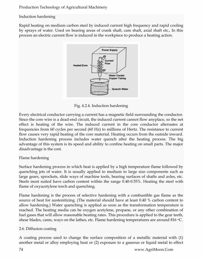
Production Technology of Agricultural Machinery
74 www.AgriMoon.Com
Induction hardening
Rapid heating on medium carbon steel by induced current high frequency and rapid cooling by sprays of water. Used on bearing areas of crank shaft, cam shaft, axial shaft etc., In this process an electric current flow is induced in the workpiece to produce a heating action.
Fig. 4.2.4. Induction hardening
Every electrical conductor carrying a current has a magnetic field surrounding the conductor. Since the core wire is a dead-end circuit, the induced current cannot flow anyplace, so the net effect is heating of the wire. The induced current in the core conductor alternates at frequencies from 60 cycles per second (60 Hz) to millions of Hertz. The resistance to current flow causes very rapid heating of the core material. Heating occurs from the outside inward. Induction hardening process includes water quench after the heating process. The big advantage of this system is its speed and ability to confine heating on small parts. The major disadvantage is the cost.
Flame hardening
Surface hardening process in which heat is applied by a high temperature flame followed by quenching jets of water. It is usually applied to medium to large size components such as large gears, sprockets, slide ways of machine tools, bearing surfaces of shafts and axles, etc. Steels most suited have carbon content within the range 0.40-0.55%. Heating the steel with flame of oxyacetylene torch and quenching.
Flame hardening is the process of selective hardening with a combustible gas flame as the source of heat for austenitizing. (The material should have at least 0.40 % carbon content to allow hardening.) Water quenching is applied as soon as the transformation temperature is reached. The heating media can be oxygen acetylene, propane, or any other combination of fuel gases that will allow reasonable heating rates. This procedure is applied to the gear teeth, shear blades, cams, ways on the lathes, etc. Flame hardening temperatures are around 816 oC.
2.6. Diffusion coating
A coating process used to change the surface composition of a metallic material with (1) another metal or alloy employing heat or (2) exposure to a gaseous or liquid metal to effect
Production Technology of Agricultural Machinery
75 www.AgriMoon.Com
diffusion into the basis metal. Impregnating the surface of steel with aluminium. chromium, silicon, beryllium and other elements. Impart high heat, corrosion and wear resistance. Heating and holding the steel parts in direct contact with one of the above elements. Diffusion coatings provide superior oxidation, corrosion and erosion resistance of the base metal up to 11500 C without spallation. Diffusion coating is a highly reliable, substate enhancing process for critical components.
2.7. Precipitation hardening or Age hardening
A process of aging that increases hardness and strength and usually decreases ductility. Hardening in metals caused by the precipitation of a constituent from a supersaturated solid solution. Increasing the hardness of an alloy by a relatively low temperature heat treatment that causes precipitation of components or phases of the alloy from the supersaturated solid solution. Also known as precipitation hardening.
Precipitation hardening, also called age hardening, is a heat treatment technique used to strengthen malleable materials, including most structural alloys of aluminium, magnesium and titanium, and some stainless steels. Spontaneous increase in hardness at room temperature with lapse in time. Precipitation is the decomposition of a solid solution into two phases of different composition viz., precipitate and solid solution. Precipitation hardening is caused by precipitation of a constituent from a super saturated solid solution by heating to some elevated temperature. In order that metals may serve useful purposes they must be shaped into required forms.

Production Technology of Agricultural Machinery
76 www.AgriMoon.Com
LESSON 11. SHOT PEENING
3.1. Introduction
Shot Peening allows metal parts to accept higher loads or to endure a longer fatigue life in service without failure. In usual applications shot peening can be done without changing the part design or its material. If you strike a part surface with a rounded object at a velocity, sufficient to leave an impression and continue until you completely cover (cold work) the entire surface then you will have peened that part.
Fig. 4.1 Shot peening
In modern usage peening is applied by throwing tiny cast steel balls or shot at high velocity hence the term ―shot peening‖. Actually the effect of peening was discovered centuries ago by sword smiths and black smiths who found the peening the surface of a sword or wagon spring would greatly increase its resistance to breaking when bent or loaded repeatedly. The reasons for this improvement were not then understood. The round knob of the ball peen hammer was the smith‘s tool for applying this process to cold (not hot) parts.
3.2. Application of shot peening
Most people do not know that in the car they drive all the coil, leaf and valve springs have been shot peened as well as the torsion rods, drive shafts, axles, and gears. In some vehicles the connecting rods and crank shaft are peened as well. If you fly, shot peening also contributes to the integrity of many of the planes parts and to your safety for shot peening works its wonders on a aluminum and titanium as well as steel parts. The wind sins and structural members will have been shot peened to improve their fatigue properties as well as to prevent stress corrosion cracking. The landing gear is shot peened and most parts in the jet engines also.

Production Technology of Agricultural Machinery
77 www.AgriMoon.Com
If the plane is a wide body type the wing skins will have been formed to the airfoil contours by a process called ―peen forming‖. This amazing process is so cost affective and versatile that the wings of new aircraft designs are possible the forming of very long tapered skins including positive or negative dihedral breaks virtually without tooling, and the side effects (addition of compressive stresses) are beneficial not detrimental.
When a thin part is peened on one side the compressive stress layer has the effect of trying to elongate the peened surface and thereby curves the part. The curve then will develop with the convex side toward the incoming shot. Peen forming is based on this effect.
Peening has little or no effect on statically loaded structures such as buildings or bridges. It works best for cyclically loaded parts (where load reversals occur frequently). Railroad wheels, rotary printing press plates, aircraft propellers, high strength fasteners, rock drilling bits, and drill rods are typically peened parts.
3.3. Shot peening for longer fatigue life
It is rare that we go from one place to another by road and not find a vehicle, either a lorry or a car broke down on the road due to fatigue failure of axle shaft or the spring and so on, thus creating obstacles in the flow of traffic and sometimes resulting in serious accidents.
These fatigue failures can be reduced and are being almost eliminated in the Western countries by the adoption of shot peening process for increasing the fatigue life of various components subjected to fatigue stress. Shot peening is just one of the applications of shot blasting for increasing the fatigue life of various components subject to fatigue stress. The reduced fatigue failures result in low maintenance and replacement cost for parts like springs, gears, axles and knuckle joints etc.
As is well known, the part which fails in fatigue, fails mainly due to its failure in tensile strength. Just as in prestressed concrete at the end of shot peening, the parts are left with residual compressive stress. When the component is subjected to the tensile load, a portion of the tensile stresses set by the load is neutralized by the residual compressive stresses left by the shot peening. Thus the effective load is greatly reduced, resulting in an increased fatigue life even to the extent of 1,500 %, or more.
Manufacturers of swords and brass utensils are well known for their denting the surface of the swords or the utensils for better life by round headed hammers called ball peen hammers. Today this is not done by hammers but by very fast moving metallic shots. Shot peening is a cold working method accomplished by pelting the surface of a metal part with round metallic shot thrown at a relatively high velocity, by means of an Airless Wheelabrator Centrifugal wheel.
Each shot acts as a tiny peen hammer, making a small dent in the surface of the metal and stretching the surface radially as it hits. The impact of the shot causes a plastic flow of the surface fibres extending to a depth depending upon the degree of impact of the shot and the physical properties of the work. Depths varying from .005‖ to .030‖ are rather common, but values either higher or lower than this range can be practical. There is momentary rise of temperature of the surface due to transformation of energy, possibly enough to affect the

Production Technology of Agricultural Machinery
78 www.AgriMoon.Com
plastic flow of surface fibres; however, the effect of shot peening is known as cold working to distinguish it from metal flow at high temperatures.
The fibres underneath the top layer, however, are not stretched to their yield point and, therefore, retain elasticity, the under fibres are, of course, bonded to the stretched surface layer and after the inner fibres force the outer fibres to return to a shorter length than that at which the stretched fibres would tend to remain, in the equilibrium which results, the surface fibres are in residual compression while the inner fibres are in tension.
The surface compression stress is several times greater than the tension stress in the interior of the section; so that when working stresses are applied that would ordinarily impose a tension stress on the surface, that tension is offset by the residual stress in the surface layer, and since as mentioned before the fatigue failures generally result from tensile stresses, not from compressive stress, the net result is considerably greater fatigue strength.
Shot peening is nowadays used with hundreds of different components some of which are given here. Railway leaf springs, automobile leaf springs, helical springs of all types, Gears of all types, axle bearings, crankshafts, pneumatic drills, milling cutters, connecting rods, cylinder blocks and value springs washers etc..Most of the shot blasting equipment could be utilized for shot peening with the proper arrangement of the shot separator. Besides there are special shot peening machines to suit the specific requirement of particular sizes and shapes of the product and the quantity of the product to be shot peened.
3.4. Facilitation of shoot peening
When a round part (steel ball) strikes a part of surface at high velocity the contact area is a point. This concentrates the impact energy in a very small area. Part of this energy is wasted in deforming and bouncing the ball but a significant amount is transferred into the part being struck causing a radial plastic flow at the impact point and may even leave a small visible crater. This plastic flow or movement of metal leaves compressive stresses in the part. Complete coverage of the overhauling ball impacts leaves a thin permanent compressive stress layer in the part surface.
Metals fail under tension (pull apart) loads and not under compressive (push together) loads. The failure crack will usually initiate at the part surface where tension stresses are highest and a stress riser exists (scratch, dent, machine mark, etc.,). When parts which have been shot peened are loaded, the failure producing tensile stresses are thus reduced by the amount of the compressive stresses pre-existing in the part surface. This lowering of the effective tensile stress will then allow the part to accept higher loading or to extend its service life significantly.
When the depth of the induced compressive stress layer exceeds the depth of all surface discontinuities (stress risers) their ability to start a crack is effectively masked. This is a very important secondary benefit.
3.5. Shot peening today is a precision process
Shot peening is the bombarding of a metal component by small spherical or non cutting particles, resulting in plastic deformation and the setting up of a compressive stress in the

Production Technology of Agricultural Machinery
79 www.AgriMoon.Com
peened surface. It is a cold working process most commonly used to prevent fatigue failure and to increase the fatigue life of components under cyclic stress conditions. The compressive stress imparted in the surface by peening serves to inhibit or reduce tensile stresses in the area where material failure would normally develop. The resulting increase in the component fatigue life is in some cases known to be as high as 1500 %.
Peening can be achieved by propelling the shot centrifugally by means of an impeller, or pneumatically in high pressure airstream using a pressure fed or ejector nozzle. Modern automatic peening machines are capable of projecting millions of steel or glass beads in seconds.
There are numerous applications where the compressive stress produced by peening, which can be as much as half the yield strength of the material, is of size and condition of the peening media, the time the workpiece is exposed to the blast stream, the size and configuration of the nozzles, angles, distances and other related factors it is possible to control accurately the depth of the compressed layer, the distribution of stress and in consequence, the greater life expectation of the workpiece.
3.6. Shot peening intensity
If one imagines a stream of spherical particles leaving a blast nozzle or a centrifugal blasting machine and striking a metal surface, the workdone to the surface depends on a number of factors. Size and material of the spherical shot is important, as is its velocity and the rate and angle at which the blast pattern sweeps across the surface. The relative work done to the surface is called the Peening intensity. Obviously it is impractical to count and weigh the particles and measure their velocity, so a simpler comparative method has been deviced to measure peening intensity.
If a flat strip of metal is shot peened on one side only it will slightly curl away from the side which has be treated and produce a convex surface. If a standard strip is used, the degree of curvature is a measure of the peening intensity, the stripe curling more at higher intensities. The standard strip is called an ―Almen Strip‖ after the man who first formalized this method. It is made from spring steel of carefully controlled quality to a size within close tolerances. It is used in three thickness called C, A and N. The C strip is thickest and N strip the thinnest. The curvature or are height, of the strip is measured with the aid of a dial gauge after the strip is placed and retained magnetically against two pairs of ball contacts a fixed distance apart. The gauge is zeroed with the unpeened strip in position. After peening the strip is replaced against the contacts with the unpeened side towards the dial gauge stem and the Almen are height is read directly in thousands of an inch or millimeters.
The three different strip thicknesses are to cater for different extremes of peening intensity. For most applications an A strip would be used, and if this gave a deflection after peening of 0.015 in this would be expressed as 0.015 in A, lighter peening, giving less than 0.006 in A, an N strip would be used. The C strip is for heavy peening of intensity, greater than 0.23 in A. Generally, are height N is three times are height A and C reading is 0.3 of that on an A strip. In practice, 80 % of all peening requirements lie between 0.012 in A and 0.020 in A.

Production Technology of Agricultural Machinery
80 www.AgriMoon.Com
When peening intensity is measured it is important to subject one side of the Almen strip to exactly the same blast conditions as the object to be peened. To do this the strip is clamped by the heads of four screws to a heavy flat block of hardened tool steel, called an Almen block, Fog. The assembly is then passed through the blast stream in the same manner and relative position as the part to be peened. On irregularly shaped components often more than one strip is used, each one positioned on a difference face requiring treatment.
3.7. Peening saturation
Although peening intensity depends on a factors concerned with the shot blast equipment (pressure, shot size, and so on ) the time of exposure to a shot blast stream is also very important. The peening intensity increased with time until a saturation points is reached where any increase in exposure time of the samples to the blast only results in a marginal increase in peening intensity. If continued blasting for a long period of time does not produced a required Almen arc height, than saturation point has been reached and either a larger shot size is required or a higher shot velocity to increase the Almen arc (at saturation). In practice, specifications of peening intensity should always be for saturation values.
3.8. Peening coverage:
It is essential if the maximum benefit from shot blasting is to be obtained that the surface is completely and uniformly covered by the minute indentations resulting from bombardment by the peening media. Generally, a peening specification should state the percentage coverage required and this would be estimated by inspecting the peening surface with the aid of magnifying glass or preferably, a microscope. Most specifications, particularly those used in the safety conscious aerospace industry, will call for 100 % coverage. At least 90 % coverage will probably be required for less stringent requirements.
3.9. Peening Media
To accomplish a shot peening job efficiently, shot of the correct material and size maintained in a condition free of cutting edges, should be used. Shot of peening is available in a variety of materials depending on the nature of the job in hand.
Cast steel shot is generally used for peening ferrous components - leaf or coil springs, for example - or for the treatment of non ferrous articles when the possibility of ferrous contamination is acceptable. It is however possible to blast components with angular non ferrous abrasive after peening with cast steel shot to remove any ferrous contamination. This is not generally done, since it would probably be cheaper to peen the article with glass beads in the first instance.
Glass beads are widely used for peening non ferrous components or where very low intensities may be required, for example on aluminum and its alloys, titanium and stainless steel, particularly in the aerospace industry where peening is widely used to increase the fatigue life on non ferrous components. Copped wire is less widely used for peening and consists of spring steel wire, or piano wire, shopped into lengths equal to its diameter. Before being used for peening it has to be blasted against a steel plate to blunt the sharp cut ends.
Production Technology of Agricultural Machinery
81 www.AgriMoon.Com
3.10. Shot Sizes
Apart from considerations of peening intensity, which are directly affected by shot size the size of shot should be small enough to fit the smallest inside radius or fillet being peened, preferably less than one third of the fillet radius. In addition, its diameter should not exceed one third of the fillet that of the smallest used including of course, the nozzle through which the shot is propelled.
To maintain the required standard of peening intensity it is vitally important that the size range of shot is that virtually all shattered particles are removed. In better quality shot blast equipment this is achieved by an efficient air wash system which removes undersize particles by passing a controlled airstream through a falling stream of peening media which has been precipitated by centrifugal means in a cyclone. For final elimination of oversize unwanted debris, the reusable particles pass through a vibrated sieve.
3.11. Peening and the designer
Main application of shot peening is to increase the fatigue life of components under cyclic stress. The process will provide optimum benefits at the design stage of a component. Peening can be usefully employed within the context of extending fatigue life in two ways. Either the fatigue life of an existing component which has revealed premature failure can be reduced considerably to give the same fatigue life. It is the latter concept that is of interest to the designer.
3.12. Selective treatment:
It is not always necessary to peen an article all over. This is particularly true where a component has an area of f particularly high stress, in which case only the highly stressed area need be peened. If selected areas only are being peened care must be taken when blending the peened and unpeened areas. An instance is where an article could be experiencing a changing stress which is not cyclic in as much as the stress does not reverse.
A case in point is a motor vehicle lead spring, where one side is constantly under tension which (is a motor vehicle) is always fluctuating during use. In this case, fatigue failure could still occur, but only form the tension side and peening need only be carried out on the tension side to produce a layer under compressive stress. If one visualizes the loaded spring, the other side is always under compressive stress. Even greater benefit can be obtained by peening with the component under stress. When the component is then released, the depth of the peened compressive layer is greater than would have been the case for normal peening and a greater fatigue resistance results.
3.13. Air blast centrifugal
Main difference between air blast and centrifugal machines is that the latter do not propel each particle to a velocity as high as that with air blast, but they produce a blast pattern containing many more particles. This means that they can handle a much greater throughput of work than an air blast machine, but to obtain the same peening intensity a larger shot size would probably need to be used. Additionally, the larger pattern of blast with varying shot velocities from the centre to the edges of the pattern produces variable peening intensities

Production Technology of Agricultural Machinery
82 www.AgriMoon.Com
over the total which for some components would be unacceptable. For many items, however, when peening to saturation, this is not a critical factor.
Centrifugal machines are widely used for heavy peening applications. Typical examples are large coil springs, torsion bars and leaf springs. For more delicate components like valve springs, push rods and rocket arms, the precision of air blast systems may be preferred. It is important to have air pressure regulation on an air blast machine. With this facility any required peening intensity can easily be achieved by a selected combination of shot size and air pressure. Equally important is the rate of feeding of the shot through the nozzle. It is important that an even controlled feed is maintained, and that the orifice through which the shot passes into the compressed air stream is either fully adjustable, or designed to accommodate a wide variation in shot size while still keeping the appropriate feed rate. Further considerations are the orifice and angle of the nozzle from the workpiece. To reproduce peening intensities accurately all these factors should be specified.
Generally centrifugal machines are used with steel shot or cut wire. Until recently it has not been possible to use glass beads on them to avoid contamination of non ferrous workpieces. Main reason for this is that the lighter beads could not be reclaimed but were drawn into the dust collection system to be wasted. This is particularly undesirable since glass bead peening media is more expensive than iron or steel shot. An additional difficulty is that the beads, being lighter than steel spheres, are slowed down by atmospheric drag on leaving the impeller, with consequent reduction in peening intensities.
The difficulty of reclaiming glass beads for further use has been solved in two ways, by using a centrifugal precipitator through which all air must pass before reaching the dust collector, and by conveying the beads for reuse on a fluidized bed incorporating an efficient classifying system for removing any remaining dust and broken bead particles. A tubular impeller has been developed for propelling the beads so as to offset the slowing down caused by air drag. The use of impeller tubes instead of flat blades has two advantages. Firstly, the track width produced parallel to the axis of the wheel is version, with a much greater, up to 100 %, peak intensity at the centre. Secondly, distribution of the blast pattern over its length normal to the axis of the wheel shows a greater area of high intensity than from a bladed version. This is especially noticeable when using fine media.
3.14. Peening is versatile
Often a technique becomes associated with a strictly limited number of applications. This leads to be the case with shot peening, where everyday procedures such as the treatment of crankshafts, gears and springs is thought by many to be the full extent of the process. In scope and scale the variety of shot peening applications is considerable. It ranges from the treatment of large aircraft undercarriage components to delicate miniaturized electronic, components subject to stress, which are shot peened with tiny glass spheres ranging from 45 to 75 micron.
Nor are the application confined to the class is fatigue situation, where a component undergoes a cyclic stress and shot peening increases fatigue life. There are other surface defects that cause metal to fail which can be inhibited by a carefully controlled peening process. Stress corrosion cranking is a problem that occurs as a result of applied stress on a
Production Technology of Agricultural Machinery
83 www.AgriMoon.Com
component in a corrosive environment. Failure would not occur in the corrosive environment alone nor under the applied stress only. It is the combination that causes the problems. If failure cannot be prevented by peening, life to failure will be certainly increased.
The peening of bearings to improve fatigue life is an obvious application, but simultaneously the bombardment results in a cratered surface formation in which lubricants are retained. This is of importance in any situation where two metal surfaces are moving in relation to each other.
The controlled hammering effect of shot peening has been proved to close the pores of metal surfaces. Vacuum chambers need to have a nonporous surface to reduce out gassing during pump down and glass bead peening is the acknowledged treatment. The treatment of castings is another obvious area where the problem of porosity can be reduced. Surface scratches and machining marks and similar tiny imperfections acting as stress raisers are the cause of premature failure and treatment with spherical peeining media can remove these imperfections. In many instances it is necessary to relieve tensile stress induced in the surface by grinding or welding during manufacture. These stresses can be modified by peening the workpiece in the appropriate areas.
Treatment by glass bead blasting is a fast effective and inexpensive method of burr removal which can be carried out in manually operated or fully automated plants. Where the components are designed for uses under stress, peening and debarring can be undertaken in the same operation.
The effect of peening which causes the Almen strips to bend can be used on metal sheets that have to be formed into a curved surface. By peening one side only and at different intensities in different places, the sheet can be induced to follow a complex curve. Even if treated on one side only, both surface layers will be under compressive stress, with a resultant improved fatigue resistance. When peen forming it is possible to machine off the microscopically cratered surface caused by the peening action, if a machined finish is required.
The principle of peen forming can, of course, be applied to straightening deformed components of thin section. Compared to mechanical methods of straightening, which can produce tensile stresses, the resultant compressive surface layer can be off benefit.
So far no mention has been made of product appearance. The finish that results from glass bead peening can be a powerful sales feature. Depending on blast intensity, varying finishes can be obtained, from a satin pearl reflective surface to a pleasing hammer effect.

Production Technology of Agricultural Machinery
84 www.AgriMoon.Com
LESSON 12 .CHEMICAL VAPOUR DEPOSITION (CVD)
4.1. Introduction
Chemical vapor deposition (CVD) is a chemical process used to produce high-purity, high-performance solid materials. The process is often used in the semiconductor industry to produce thin films. In a typical CVD process, the wafer (substrate) is exposed to one or more volatile precursors, which react and/or decompose on the substrate surface to produce the desired deposit. Frequently, volatile by-products are also produced, which are removed by gas flow through the reaction chamber.
Micro fabrication processes widely use CVD to deposit materials in various forms, including: monocrystalline, polycrystalline, amorphous, and epitaxial. These materials include: silicon, carbon fiber, carbon nano fibers, filaments, carbon nanotubes, SiO2, silicon-germanium, tungsten, silicon carbide, silicon nitride, silicon oxynitride, titanium nitride, and various high-k dielectrics. The CVD process is also used to produce synthetic diamonds.
Chemical vapour deposition or CVD is a generic name for a group of processes that involve depositing a solid material from a gaseous phase and is similar in some respects to physical vapour deposition (PVD). PVD differs in that the precursors are solid, with the material to be deposited being vaporised from a solid target and deposited onto the substrate.
Chemical gas sources are thermally, optically, or electrically (plasma) reacted with a surface to ―leave‖ behind deposits with reaction byproducts pumped out of the reaction tube or vacuum chamber.
Fig. 4.4.1. Schematic diagram of CVD Hot wall- reduced pressure reactor

Production Technology of Agricultural Machinery
85 www.AgriMoon.Com
Fig. 4.4.2 schematic diagram of CVD Continous- atmospheric pressure reactor
4.2. Types of CVD Processes
CVD covers processes such as
Atmospheric Pressure Chemical Vapour Deposition (APCVD)
Low Pressure Chemical Vapour Deposition (LPCVD)
Metal-Organic Chemical Vapour Deposition (MOCVD)
Plasma Assisted Chemical Vapour Deposition (PACVD) or Plasma Enhanced Chemical Vapour Deposition (PECVD)
Laser Chemical Vapour Deposition (LCVD)
Photochemical Vapour Deposition (PCVD)
Chemical Vapour Infiltration (CVI)
Chemical Beam Epitaxy (CBE)
4.2.1. Atmospheric Pressure CVD (APCVD)
With the CVD method under atmospheric pressure (atmospheric pressure CVD; PCVD), without evacuation of the process plant, at a temperature of about 400 ° C oxide layers possibly together with foreign substances isolated. The required elements silicon and oxygen are the gases Silane SiH4 and O2 by adding nitrogen. To Siliziumoxid bildung then run the following reactions:
SiH4 + 2O2 -> SiO2 + 2H2O
SiH4 + O2> 2H2 + SiO2
Because of the low temperature process are only small values of conformity, so that edges with significantly less material to be covered than the horizontal surfaces. By the addition of

Production Technology of Agricultural Machinery
86 www.AgriMoon.Com
ozone is the dynamics of particles anlagernden influenced so that their agility on the substrate. Dick differences can be balanced and thus compliance should be increased.
To defuse the following in the structuring of the oxide layer resulting sharp edges, achieved by the addition of gases phosphine and Diboran the integration of phosphorus and boron in the Oxidstruktur. This is below the melting point of 900 °C humiliated, so that by momentary melting of the hard layer breaks defused. This is for the quality of metal contacts that angry at highly miniaturized structures important.
Advantages : High deposition rates, simple, high throughput
Disadvantages : Poor uniformity, purity is less than LPCVD
Use : mainly for thick oxides.
4.2.2. Low Pressure CVD (LPCVD)
In this application for the production of films with low thickness of silicon, nitrides, but also of polysilicon and tungsten, the plant evacuated reaction (correspondingly low pressure CVD, LPCVD). Among the low-pressure conditions (in the range 10 to 100 Pa) is the movement dynamics considerably more favorable for the deposition of layers of conformity as high as under atmospheric pressure. Through mutual clashes are also Gaspartikel here by the linear movement discouraged. The average distance between collisions, however, lies in the range of centimeters, so that together with the high mobility of the deposited particles in the high process temperature of 900 °C is the material into low-lying areas can penetrate. Thus, a uniform deposition. There may be values of the conformity of a K near achieved (upto 0.98). The procedure exceeds the APCVD technology reached regarding the density and electrical quality.
Advantages : Excellent uniformity, purity
Disadvantages : Lower (but reasonable) deposition rates than APCVD
Use : for polysilicon deposition, dielectric layer deposition, and doped dielectric deposition.
It can be used for a variety of materials:
Polysilicon for gate contacts
Thick oxides used for isolation between metal interconnects
Doped oxides useful for global planarization
Nitrides and other dielectrics for isolation or capacitors
Metals for seed layers for vias and interconnect lines

Production Technology of Agricultural Machinery
87 www.AgriMoon.Com
4.2.3. Metal Organic CVD (MOCVD)
Advantages : Highly flexible—> can deposit semiconductors, metals, dielectrics
Disadvantages : HIGHLY TOXIC!, Very expensive source material. Environmental disposal costs are high.
Uses : Dominates optical (but not electronic) III-V technology, some metalization processes (W plugs and Cu)
4.2.4. Plasma Enhanced CVD (PECVD)
With the plasma enhanced CVD process is the deposition at temperatures around 300°C allows, which does not destroy other structures (such as aluminum structures, which at 500°C melt). The temperature in this alone will not onset of decomposition reactions of the process gases will be through encouragement of a plasma with high frequency electric fields triggered.
The silicon is on the gas SiH2Cl2, of which it is at relatively low temperatures separates. With the support of the plasma excitation are the low process temperatures at 300 ° C is possible.
The deposition of SiO2 and silicon nitride Si3N4 at low conformity (k <0.8) but high growth speed (up to 500 nm / min), is hereby possible.
It can process multiple installations by a gripper automated control. These are the wafer into a warehouse. From there they will then lock on an interim, the pressure differences bridged in the process of the separation chamber passed. Plasmas are used to force reactions that would not be possible at low temperature.
Advantages : Uses low temperatures necessary for rear end processing.
Disadvantages : Plasma damage typically results.
Use : for dielectrics coatings.
4.3. Coating Characteristics
CVD coatings are typically:
Fine grained
Impervious
High purity
Harder than similar materials produced using conventional ceramic fabrication processes
CVD coatings are usually only a few microns thick and are generally deposited at fairly slow rates, usually of the order of a few hundred microns per hour.

Production Technology of Agricultural Machinery
88 www.AgriMoon.Com
4.4. CVD Apparatus
A CVD apparatus will consist of several basic components:
Gas delivery system: For the supply of precursors to the reactor chamber
Reactor chamber: Chamber within which deposition takes place
Substrate loading mechanism: A system for introducing and removing substrates, mandrels etc
Energy source: Provide the energy/heat that is required to get the precursors to react/decompose.
Vacuum system: A system for removal of all other gaseous species other than those required for the reaction/deposition.
Exhaust system: System for removal of volatile by-products from the reaction chamber.
Exhaust treatment systems: In some instances, exhaust gases may not be suitable for release into the atmosphere and may require treatment or conversion to safe/harmless compounds.
Process control equipment: Gauges, controls etc to monitor process parameters such as pressure, temperature and time. Alarms and safety devices would also be included in this category.
4.5. Energy Sources
There are several suitable sources of heat for CVD processes. These include:
Resistive Heating e.g. tube furnaces
Radiant Heating e.g. halogen lamps
Radio Frequency Heating e.g. induction heating
Lasers
Other energy sources may include UV-visible light or lasers as a source of photo energy.
4.6. Precursors
Precursor gases (often diluted in carrier gases) are delivered into the reaction chamber at approximately ambient temperatures. As they pass over or come into contact with a heated substrate, they react or decompose forming a solid phase which and are deposited onto the substrate. The substrate temperature is critical and can influence what reactions will take place.
Production Technology of Agricultural Machinery
89 www.AgriMoon.Com
Materials are deposited from the gaseous state during CVD. Thus precursors for CVD processes must be volatile, but at the same time stable enough to be able to be delivered to the reactor. Generally precursor compounds will only provide a single element to the deposited material, with others being volatilised during the CVD process. However sometimes precursors may provide more than one. Such materials simplify the delivery system, as they reduce the number of reactants required to produce a given compound.
Typical Precursor Materials
CVD precursor materials fall into a number of categories such as:
Halides - TiCl4, TaCl5, WF6, etc
Hydrides - SiH4, GeH4, AlH3(NMe3)2, NH3, etc
Metal Organic Compounds
Metal Alkyls - AlMe3, Ti(CH2tBu)4, etc
Metal Alkoxides - Ti(OiPr)4, etc
Metal Dialylamides - Ti(NMe2)4, etc
Metal Diketonates - Cu(acac)2, etc
Metal Carbonyls - Ni(CO)4, etc
Others – include a range of other metal organic compounds, complexes and ligands.
Materials That Can be Produced by CVD Processes
CVD is an extremely versatile process that can be used to process almost any metallic or ceramic compound. Some of these include:
Elements
Metals and alloys
Carbides
Nitrides
Borides
Oxides
Intermetallic compounds

Production Technology of Agricultural Machinery
90 www.AgriMoon.Com
CVD Gas Products
An often neglected by-product of the CVD process are volatile gases. However, these gases may be toxic, flammable or corrosive so must be treated appropriately. Analysis of the off-gases can also lead to a better understanding of the CVD reaction mechanisms and the information used to refine the process.
4.7. Applications
CVD has applications across a wide range of industries such as:
Coatings: Coatings for a variety of applications such as wear resistance, corrosion resistance, high temperature protection, erosion protection and combinations thereof.
Semiconductors and related devices: Integrated circuits, sensors and optoelectronic devices
Dense structural parts: CVD can be used to produce components that are difficult or uneconomical to produce using conventional fabrication techniques. Dense parts produced via CVD are generally thin walled and maybe deposited onto a mandrel or former.
Optical Fibers: For telecommunications.
Composites: Preforms can be infiltrated using CVD techniques to produce ceramic matrix composites such as carbon-carbon, carbon-silicon carbide and silicon carbide-silicon carbide composites. This process is sometimes called chemical vapour infiltration or CVI.
Powder production: Production of novel powders and fibres
Catalysts
Nanomachines

Production Technology of Agricultural Machinery
91 www.AgriMoon.Com
MODULE 5. Industrial lay out planning and quality management
LESSON 13. LIMITS, FITS AND TOLERANCE
1.1 Limits Fits and Tolerance
Two extreme permissible sizes of a part between which the actual size is contained are called limits. The relationship existing between two parts which are to be assembled with respect to the difference on their sizes before assembly is called a fit. Tolerance is defined as the total permissible variation of a size. It is the difference between maximum limit and minimum limit of size.
1.2 Fits
When two parts are to be assembled the relation resulting from the difference between their sizes before assembly is called a fit. The fit signifies the range of tightness or looseness which may result from the application of a specific combination of allowances and tolerances in the design of mating parts.
1.2.1 Types of Fits
The three types of fits are shown in Fig. 1.1 The disposition of tolerance zones for the three classes of fit are shown in Fig. 1.2.
Fig. 1.1 Types of fits

Production Technology of Agricultural Machinery
92 www.AgriMoon.Com
Fig. 1.2 Disposition of tolerance zones for the three classes of fit
There are three general types of fit between the mating parts
1. Clearance fit: A clearance fit is one having limits of size so prescribed that a clearance always results when mating parts are assembled.
2. Interference fit: An interference fit is one having limits of size so prescribed that an interference always results when mating parts are assembled.
3. Transition fit: A transition fit is one having limits of size so prescribed that either a clearance or interference may always result when mating parts are assembled.
1.3 Terminology
The terminology used in fits and tolerances is shown in Fig. 1.3. The important terms are
1.3 Terminology for fits and tolerances
Basic size: It is the exact theoretical size arrived at by design. It is also called nominal size.
Actual size: The size of a part as may be found by measurement.
Maximum limit of size: The greater of the two limits of size.
Minimum limit of size: The smaller of the two limits of size.

Production Technology of Agricultural Machinery
93 www.AgriMoon.Com
Allowance: It is an intentional difference between maximum material limits of mating parts. It is a minimum clearance or maximum interference between mating parts.
Deviation: The algebraic difference between a size (actual, maximum, etc.) and the corresponding basic size.
Actual deviation: The algebraic difference between the actual size and the corresponding basic size.
Upper deviation: The algebraic difference between the maximum limit of size and the corresponding basic size.
Upper deviation of hole = ES (& art Superior)
Upper deviation of shaft es
Lower deviation: The algebraic difference between the minimum limit of size and the corresponding basic size.
Lower deviation of hole = El (Ecart Inferior)
Lower deviation of shaft = ei
Upper deviation Lower deviation + Tolerance
Zero line: It is the line of zero deviation and represents the basic size.
Tolerance zone: It is the zone bounded by the two limits of size of the parts and defined by its magnitude, i.e. tolerance and by its position in relation to the zero line.
Fundamental deviation: That one of the two deviations which is conveniently chosen to define the position of the tolerance zone in relation to zero line, as shown in fig. 1.4.
Fig. 1.4 Disposition of fundamental deviation and tolerance zone with respect to the zero line
Basic shaft: A shaft whose upper deviation is zero.
Basic hole: A hole whose, lower deviation of zero.
Clearance: It is the positive difference between the hole size and the shaft size.

Production Technology of Agricultural Machinery
94 www.AgriMoon.Com
Maximum clearance: The positive difference between the maximum size of a hole and the minimum size of a shaft.
Minimum clearance: The positive difference between the minimum size of a hole and the maximum size of a shaft.
1.4 Standard Tolerances
There are 18 standard grades of tolerances as specified by BIS with designations ITOI, ITO and IT to IT 16.
The standard tolerances for the various grades are given in Table 1.1 and tolerance grades for various manufacturing processes in Table 1.2
Table 1.1 Standard tolerances.
Table 1.2 Tolerance grade in various manufacturing processes.

Production Technology of Agricultural Machinery
95 www.AgriMoon.Com
1.5 Hole Basis and Shaft Basis for Fits
1. Hole basis system: In this system, the different clearances and interferences are obtained in associating various shafts with a single hole, whose lower deviation is zero.
2. Shaft basis system: In this system, the different clearances and interferences are obtained in associating various holes with a single shaft, whose upper deviation is zero.
1.6 Selection of Fits
Hole basis system is the most commonly used system because due to the fixed character of hole production tools, it is difficult to produce holes with odd sizes. Commonly used types of fits are given in Table 1.3. Shafts ‗a‘ to ‗h‘ produce clearance fit, ‗j‘ to ‗n‘ transition fit, and ‗p‘ onwards interference fit with hole.
Table 1.3 commonly used fits

Production Technology of Agricultural Machinery
96 www.AgriMoon.Com
1.7 Dimensioning of Tolerances -Rules
1. The upper deviation should be written above the lower deviation value irrespective of whether it is a shaft or a hole (Fig. 1.5 (a)).
2. Both deviations are expressed to the same number of decimal places, except in the cases where the deviation in one direction is nil (Fig. 1.5 (b)).
3. Tolerances should be applied either to individual dimensions or by a general note, assigning uniform or graded tolerances (Fig. 1.5 (c)).
4. The use of general tolerance not greatly simplifies the drawing and saves much labour in its preparation. On the drawing, the limits on a dimension can be specified in two ways, i.e. (i) unilateral, and (n) bilateral. In unilateral tolerance system, the variation in size is permitted in one direction
1.8 Limit Gauges
Two sets of limit gauges are necessary for checking the size of various parts. There are two gauges: Go limit gauge, and Not Go limit gauge.

Production Technology of Agricultural Machinery
97 www.AgriMoon.Com
1. Go Limit: The Go limit applied to that of the two limits of size corresponds to the maximum material condition, i.e. (1) an upper limit of a shaft, and (ii) the lower limit of a hole. This is checked by the Go gauge.
2. Not Go Limit: The Not Go limit applied to that of the two limits of size corresponds to the minimum material condition, i.e. (1) lower limit of a shaft, and (ii) the upper limit of a hole. This is checked by the Not Go gauge.
1.9 Machining Symbols
During the manufacture of a machine, some surfaces of a component are to be machined, which are required to be indicated in the drawing. This will enable the pattern maker to provide machining allowance on that surface. Similarly, the grade of surface finish is required to be indicated on the surface to enable the machinist to carry out the job accordingly. Thus, on production drawings it is necessary to indicate the surfaces to be machined or finished by certain specific symbols. The machining symbol is indicated to the left of the system as shown in Fig. 1.6. The value of allowance is expressed in mm.
Fig. 1.6 Indication of machining allowances
The basic symbol used for indication of surface roughness consists of two legs of unequal length inclined at 600 to the line representing the surface under consideration, as shown in fig. 1.7. It may only be used alone when the meaning is expressed by a note.
Fig. 1.7 Basic symbol for indication of surface roughness
The following guidelines may be used while specifying the machining symbols:
1. When the surface is produced by any method, it is indicated as shown in Fig. 1.8 (a).
2. When the removal of material by machining is required, a bar is added to the basic symbol, as shown in Fig. 1.8 (b).

Production Technology of Agricultural Machinery
98 www.AgriMoon.Com
3. Whenever the removal of material is not permitted In a circle is added to the basic symbol, as shown n Fig. 1.8 (c).
Fig. 5.8 Symbols used for indication of surface roughness
4. When some special surface characteristics are to be indicated (say a milled surface), a line added to the longer leg of the basic symbol, as shown in Fig. 1.8.
1.9.1 Indication of Surface Roughness
The roughness values Ra (urn) are given in Table 1.4
Table 1.4 Surface roughness values, Ra (a m)
The value defining the roughness value Ra in micron and roughness grade symbols are given on production drawings as shown in Fig. 1.9.
Fig. 1.9 Indication of surface roughness in micrometers or roughness grade symbols
When it is necessary to specify the maximum and minimum limits of the surface roughness, both the values or grades should be given as shown in Fig. .10.
Fig. 1.10 Invocation of the maximum and minimum limits of surface roughness.
2. If it is necessary to indicate the sampling length, it is shown adjacent to the symbol (Fig.
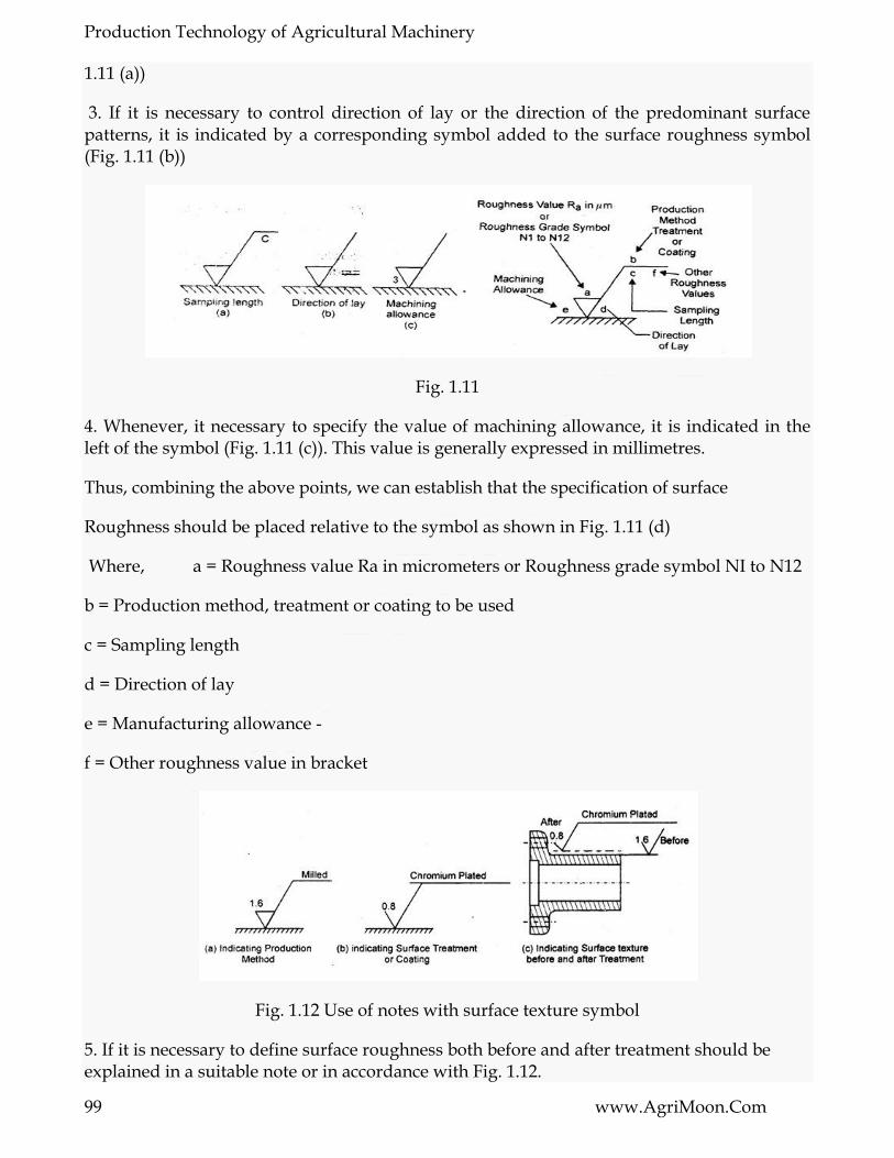
Production Technology of Agricultural Machinery
99 www.AgriMoon.Com
1.11 (a))
3. If it is necessary to control direction of lay or the direction of the predominant surface patterns, it is indicated by a corresponding symbol added to the surface roughness symbol (Fig. 1.11 (b))
Fig. 1.11
4. Whenever, it necessary to specify the value of machining allowance, it is indicated in the left of the symbol (Fig. 1.11 (c)). This value is generally expressed in millimetres.
Thus, combining the above points, we can establish that the specification of surface
Roughness should be placed relative to the symbol as shown in Fig. 1.11 (d)
Where, a = Roughness value Ra in micrometers or Roughness grade symbol NI to N12
b = Production method, treatment or coating to be used
c = Sampling length
d = Direction of lay
e = Manufacturing allowance -
f = Other roughness value in bracket
Fig. 1.12 Use of notes with surface texture symbol
5. If it is necessary to define surface roughness both before and after treatment should be explained in a suitable note or in accordance with Fig. 1.12.

Production Technology of Agricultural Machinery
100 www.AgriMoon.Com
LESSON 14. MICRO STRUCTURE ANALYSIS OF METALS
4.1 Introduction
The engineering metals always play an important role in an industry, because the process of all manufacturing starts with the raw material. These are broadly divided into two groups, i.e., metals and non metals. A metal may be described as a material which is solid at room temperature, has relatively high density, high, melting temperature, low specific heat, good electrical and thermal conductivity, strength, hardness, etc. Most metals are elastic to a limit: they deform in proportion to stress and return to the original state when the stress is released. At higher stresses they deform plastically. Some metal will accept a deal of plastic deformation before failure.
A metal can exist in the gaseous, liquid and solid state. The state depends on the pressure exerted on the metal and on its temperature. A molecule is the smallest particle of an element or compound that can stay independently. A molecule that consists of one atom is called a monoatomic (Ex. rare gases). Diatomic molecules are those which are made of two atoms (Ex.hydrogen, nitrogen, oxygen). Polyatomic molecules are those which contain more than two atoms; phosphorus molecules contain four atoms.
Atom: It may be defined as smallest particular that retains the physical characteristics of that element. Atoms occupy fixed positions and strong bonds exist between them. Atoms are located at sites, which are divided by the structure of the atoms and nature of bonds. Combination of properties of atom and the way in which they are assembled determines the mechanical properties of particular metal.
Matter: May be defined as a collection of atoms whose position and behavior determines its properties and characteristics.
The materials chiefly used in the shops are metals which may be broadly divided into the following two groups.
Ferrous metals: The metals which contain iron as their chief constituent are called ferrous metals. The various ferrous metals used in industry are pig iron, cast iron, wrought iron, steel etc.
Non-ferrous metals: The metals which contain a metal other than iron as their chief constituent are called non-ferrous metals. The various nonferrous metals used in industry are aluminium, copper, zinc, leaf, brass, tin etc.
The non-metals in the solid state are mostly brittle and poor electrical and thermal conductors. They do not form alloy but combine chemically to form compound. Some of the non-metals are glass, plastics, wood, concrete etc.
4.2. Structure of solids

Production Technology of Agricultural Machinery
101 www.AgriMoon.Com
There are two types of solids. They are crystalline and amorphous. All solid substance is either amorphous solids or crystalline solids.
4.2.1. Amorphous solids
In the amorphous solids, the atoms are arranged chaotically, i.e., the atoms are not arranged in a systematic order. Amorphous solids are solids with random unoriented molecules. Amorphous solid substance does not possess long-range order of atoms positions. The common solids are wood, plastics, glass, paper, rubber etc.
4.2.1.2 Crystalline solids
In crystalline solids, the atoms making up the crystals arrange themselves in a definite and orderly manner and form. Crystalline solids are arranged in fixed geometric patterns or lattices. All solid metals such as iron, copper, aluminium etc are crystalline solids. The arrangement of atoms in the amorphous solids or crystalline solids is shown in Fig.4.1 below.
Fig. 4.1 Structure of solids
4.3. Metals crystal structure
A crystal structure is a unique arrangement of atoms in a crystal. A crystal is a periodic array of atoms. The crystal structure of a material or the arrangement of atoms in a crystal can be described in terms of its unit cell. A crystal is composed of unit cells. A unit cells contains the smallest number of atoms, which when taken together have all properties of the crystal of the particular metal. The lengths of the edges of a unit cell and the angles between them are called the lattice parameters.
Crystals are conceptually built up from unit cells. The Unit cell is the basic building block for a crystal. The unit cell is defined as the smallest parallelepiped which could be transposed in three coordinate directions to build the space lattice. The space lattice of various substances differ in the size and shape of their unit cells. A crystal is basically a whole bunch of unit cells stacked end to end in 3D. Six parameters describe the shape of the unit cell - the length of the unit cell edges (a,b,c) and the angles between them (alpha, beta, gamma). The angle alpha (α) is the angle between the b and c cell edges, beta (β) between a and c, gamma (γ) between a and b. a, b, c represent the vectors of the edges of the unit cell, in whatever coordinate system it is used. Minerals belonging to the same crystal system have the same shaped unit cell The length of the edges of the unit cell vary depending upon the types of atoms and how they are

Production Technology of Agricultural Machinery
102 www.AgriMoon.Com
arranged. The unit cell is given by its lattice parameters, the length of the cell edges and the angles between them, while the positions of the atoms inside the unit cell are described by the set of atomic positions (xi,yi,zi) measured from a lattice point.
Fig.4.2 shows the unit cell of a three dimensional crystal lattice. It is formed by the primitives or intercepts a, b, and c along the three axes respectively. The three angles are called (alpha, beta, gamma) are called interfacial angles. Both the intercepts and interfacial angles constitute the lattice parameters of the unit cell.
Fig.4.2. Lattice arrangement of a unit cell.
4.4. Crystal system
The crystal systems are a grouping of crystal structures according to the axial system used to describe their lattice. Each crystal system consists of a set of three axes in a particular geometrical arrangement. There are seven unique crystal systems. The simplest and most symmetric, the cubic (or isometric) system, has the symmetry of a cube. The seven basic crystal systems are cubic, tetragonal, hexagonal, orthorhombic, rhombohedral, monoclinic and triclinic.
4.5. Crystal lattice
The definite and orderly manner and form of the atoms producing a small, repeating, three dimensional, geometrical pattern in aggregate is called crystal lattice or space lattice. The following three types of crystal lattice are usually found in most of the metals. There are fourteen possible types of space lattices in these seven crystal systems. But the following three types are usually found in most of the metals.
4.5.1. Body centered cubic (BCC) space lattice
In body centered cubic space lattice, there are nine atoms. The eight atoms are located at the corners of the cube and one atom at it centre. This type of lattice is found in alpha iron, tungsten, chromium, manganese, molybdenum, tantalum, barium, vanadium etc.,
4.5.2. Face centered cubic (FCC) space lattice
In face centered cubic space lattice, there are fourteen atoms. The eight atoms are located at the corners of the cube and six atoms at the centers of six faces. This type of lattice is found in gamma iron, aluminum, copper, lead, silver, nickel, gold, platinum, calcium etc.,

Production Technology of Agricultural Machinery
103 www.AgriMoon.Com
Fig. 4.3. Crystal lattice
4.5.3. Closed packed hexagonal (CPH) space lattice
In close packed hexagonal space lattice, there are seventeen atoms. The twelve atoms are located at the twelve corners of the hexagonal prism, one atom at the centre of each of the two hexagonal faces and three atoms are symmetrically arranged in the body of the cell. This type of lattice is found in zinc, magnesium, cobalt, cadmium, antimony, bismuth, beryllium, titanium, zirconium etc.,
4.6. Formation of grains.
Grain is a small region of a metal, having a given and continuous crystal lattice orientation. Each grain represents small single crystal. Grains form as a result of solidification or other phase transformation processes. Grains shape and size change in course of thermal treatment processes. The normal grain size varies between 1µm to 1000 µm. Grain structure of a solid is an arrangement of differently oriented grains, surrounded by grain boundaries. All metals are crystalline and crystals are made up of several atoms. Grains are formed when he liquid metal solidifies. The process of solidification or crystallization will proceed if the liquid is cooled below the equilibrium temperature (tempo at which the given metal exists simultaneously in a liquid and solid phase) of solidification.
The solidification commences by the formation of small nuclei scattered at random in the cooling liquid. At these points, a few atom assume an orderly arrangement to give the unit cubic structure and growth takes place in three dimensions. The individual crystal or gains are aggregated to form the visible mass of a solid metal. Solidification or freezing is started when two or more atoms associate themselves to form a very small crystal, called nuclei. This may happen simultaneously at a number of locations throughout the liquid metal. This means that a number of nuclei form within the solidifying metal as it continuous to cool. The small crystal or the nucleus develops in the freezing of a liquid metal in the form of dendrites (dendron is a Greek word meaning a tree). A dendrite consisting of unit cells, which are then formed on the original straight line and so on as shown in fig. First long branches known as primary axis of the dendrite is formed and then the branches evolve from their edges and grow as secondary axis. Lastly, the tennary axis evolve and grow on secondary axis. This action is called nucleation or crystal growth and continues until all the metal between the branches has solidified.

Production Technology of Agricultural Machinery
104 www.AgriMoon.Com
Grain - A solid polyhedral (or many sided crystal) consisting of groups of atoms bound together in a regular geometric pattern
Fig. 4.4. Growth of a metal dendrite
As the dendrite grows, the spaces between its arms fill up. Outward growth stops when growing arms meet others. Eventually the entire liquid solidifies, and there is little trace of the original dendritic structure, only the grain into which the dendrites have grown.
Fig. 4.5. Solidification of a metal
Each crystal of proper geometrical form but having different orientation grows outward until it comes in contact with the adjacent crystal as depicted in Fig.4.4. The crystal growth is then gradually distorted due to interference of each crystal within its neighbors. Consequently, the crystals observed in the fracture of a metal of irregular shape are called grains. The final solid is said to be polycrystalline because of many crystals or grains of different orientations exist init. Within each crystal the atoms may be ―packed together ― in geometrical pattern. Grain is a small region of a metal, having a given and continuous crystal lattice orientation. Each grain represents small single crystal.

Production Technology of Agricultural Machinery
105 www.AgriMoon.Com
A boundary known as grain boundary is formed between two adjacent crystalline growths because of different orientations of the grains. If the orientations of the grains would not differ, they would unite, and there would not have any grain boundary. The crystals outward growth is stopped by impingement on adjacent crystals. The contact surfaces formed by adjacent crystals (because of orientation other grains) are called grain boundary. Grain boundaries interrupt the continuity of the lattice planes and increase the resistance of the metal to cold deformation. A grain boundary is the interface between two grains in a polycrystalline material. The grain boundary refers to the outside area of a grain that separates it from the other grains.
Fig. 4.6. Stages in solidification of metals
(a) Formation of nuclei (b) Growth of nuclei into crystal; (c) Joining together of crystals to form grains and associated grain boundaries
Each crystal or the grain is built up of thousands of small unit cells or cubes. The axes of the cubes all point in the same direction, but this direction vary from one crystal to another. This effect is called as orientation of the atoms. The orientation of the atomic pattern in a given crystal but varies from grain to grain. The grain size has an important effect on the mechanical properties of metal such as strength, ductility, hardness etc.

Production Technology of Agricultural Machinery
106 www.AgriMoon.Com
LESSON 15. INDUSTRIAL LAYOUT PLANNING AND QUALITY MANAGEMENT
5.1 Introduction
In a manufacturing organization, a job to be manufactured spends most of the time in moving and waiting. For reduction of this moving and waiting time of jobs/parts, it is necessary to have proper layout and proper scheduling procedure. Plant layout specifies the position of the overall arrangement of the various facilities such as equipments, material, manpower, materials handling, service facilities, and passage required to facilitate efficient operation of production system of the plant within the area of the site selected previously.
Shop layout in manufacturing plant also forms an integral part of factory planning or plant layout. Plant layout begins with the design the position of the factory building and goes up to the location and movement of a work table of the machine. All the manufacturing facilities such as equipments, raw materials, machinery, tools, fixtures, workers, etc. are given a proper place in each shop of the manufacturing plant.
Plant layout of an industrial organization plays an important role in scientific management and is defined as : ―Plant layout is such a systematic and efficient functional arrangement of various departments, machines, tools, equipment and other supports services of an industrial organization that will facilitate the smooth processing of the proposed or undertaken product in the most effective, most efficient and most economical manner in the minimum possible time‖ Plant layout of an industrial organization comprises of all the aspects connected with the industrial enterprise, viz., grounds, buildings, machinery, equipment, departments, methods of manufacturing, factory services, material handling, flow of production, working conditions, hygiene, labor and shipment of goods, etc. It does not necessarily mean planning a new enterprise only. However, it also involves minor improvements, here and there, in the existing layout, expansion of the existing plant, re-layout of the existing plant and layout of a new proposed plant.
In a best possible plant layout, material handling and transportation is minimized and efficiently controlled. Bottlenecks and points of congestions are eliminated so that the raw material and semi-finished goods move fast from one work station to another. Work stations are designed suitably to facilitate the smooth processing of the proposed or undertaken product in the most effective, most efficient and most economical manner in the minimum possible time. Optimal spaces are allocated to production centers and service centers. The primary goal of plant layout is to maximize profits by setting up the best possible arrangements of all plant facilities to the maximum advantage of reducing the cost of production of the proposed product.
5.2 Objectives of Good Plant Layout
Good plant layout comprises of best possible arrangement of the buildings, men, machine and materials for processing a under taken product. The main objectives of a good plant
Production Technology of Agricultural Machinery
107 www.AgriMoon.Com
layout involves minimum material movement, smooth flow of the product in the plant, full utilization of the space of the plant, provide adequate safety and satisfaction to the plant workers, evolve sufficient flexibility in the arrangement of the above factors so as to suit the minor future changes, if any and facilitates an effective supervision. It helps to integrate all the above factors in such a way that the best compromise and coordination among them is achieved. The movements of workers and manufacturing staffs within the plant are minimized. Waiting time of the semi-finished and finished products should be reduced to the minimum. Working conditions as far as possible should be safer and better for the satisfaction of the workers. There should be an increased flexibility for changes in product design and for future expansion. There should be full utilization of whole space of the shop and plant layout. The work methods and reduced production cycle times should be improved and the plant maintenance must be simpler. There should be increased productivity and better product quality with reduced capital cost. A good layout facilitates materials to move through the plant at the desired speed with the minimum possible cost.
5.3 Important Factors for Installation of a Plant
The important factors while planning for installation of plant include availability of space, power, water, raw material, good climatic conditions, good means of communication, ancillaries, low local taxes and similar other economic considerations, marketing facilities for the planned product, space for process disposal and skilled and unskilled labor locally. One has to keep in mind the possibilities of utilization and sale of the process wastes and by-products of the planned industry. Decision of manufacturing new product, financial and other aids, facilities for expansion presence of related industries, local bylaws and securities, hospitality are also important factors which one must keep in mind for location of an enterprise. After finalizing the size and location of the plant, the next step is to design the inner layout of the plant to plan out the sequence of different shops and their locations accordingly to specifications of material and product, manufacturing processes, type of production, material handling facilities, system and facilities for storing, inter-dependability of one shop over the other, links among various shops, service facilities and lighting and ventilation. Next, the internal arrangement of the above mentioned infrastructural facilities of different shops are identified. This identification is termed as shop layout. The main factors namely size and type of equipment, number of machines to be installed, floor area required for working on each machine, power requirements for the machines, requirements of factory services, sequence of operations to be followed, visibility to all the machines for proper supervision and control, type of drive used, safe working conditions, provision of stores within the shop, i.e. for tools, instruments, finished parts and consumable materials, etc. affects the layout of the plant. A good plant layout should meet the following basic requirement:
1. Integration of manufacturing centre facilities in terms of man, machine and material.
2. Movements of production personnel and material handling should be minimized.
3. Smooth and continuous flow of production or manufacturing work with least possible bottlenecks and congestion points.
4. Floor space utilization should be optimum as for as possible.
Production Technology of Agricultural Machinery
108 www.AgriMoon.Com
5. Working place should be free from pollution and safe working conditions should prevail in each shop of the plant.
6. The handling of raw material, semi finished and finished product should be should be tackled optimally and effectively
7. Plant layout and shop layouts must be flexible to facilitate changes in production requirements
8. There should be better working environment in term of proper light, ventilation and other amenities such as drinking water and toilets for welfare for the manufacturing personnel
5.4 Merits of a Good Plant Layout
The main advantages of a good plant layout involve effectively and economical utilization of entire floor space of the plant, increased rate of production, reduced men and machine hours per unit of production, reduced material handling, minimal production delays, effective utilization of men, machinery, material and other factory support services, reduced overall production time, elimination of large amount of paper work, significant reduction in the indirect expenses, considerable reduction in inventory work for material, promote effective supervision, facilitate easy flow of men, tools and material, promote flexibility in arrangement to suit the future changes, promotes better planning and effective control, facilitates better and easier maintenance of plant and machinery, provides safer and healthier working conditions thereby improving the morale of the workmen, provides the material as well as psychological satisfaction to the workers and enhance overall efficiency of the plant. The major merits of a good plant layout are given as under:
1. Reduced men and machine hours per unit of production
2. Effectively and economical utilization of entire floor space of the plant
2. Work flow is smooth and continuous
3. Work in process inventory is less
4. Production control is better
5. Manufacturing time is less
6. Relatively less floor area is required
7. Material handling is less.
5.5 Types of Layouts
The fulfilling the objectives of a good layout as per yearly product requirement and product types, the layouts are classified into four major categories namely fixed or position layout, line or product layout, process or functional layout and combination or group layout. Each kind of layouts is explained with respective merit, demerits and application as under.
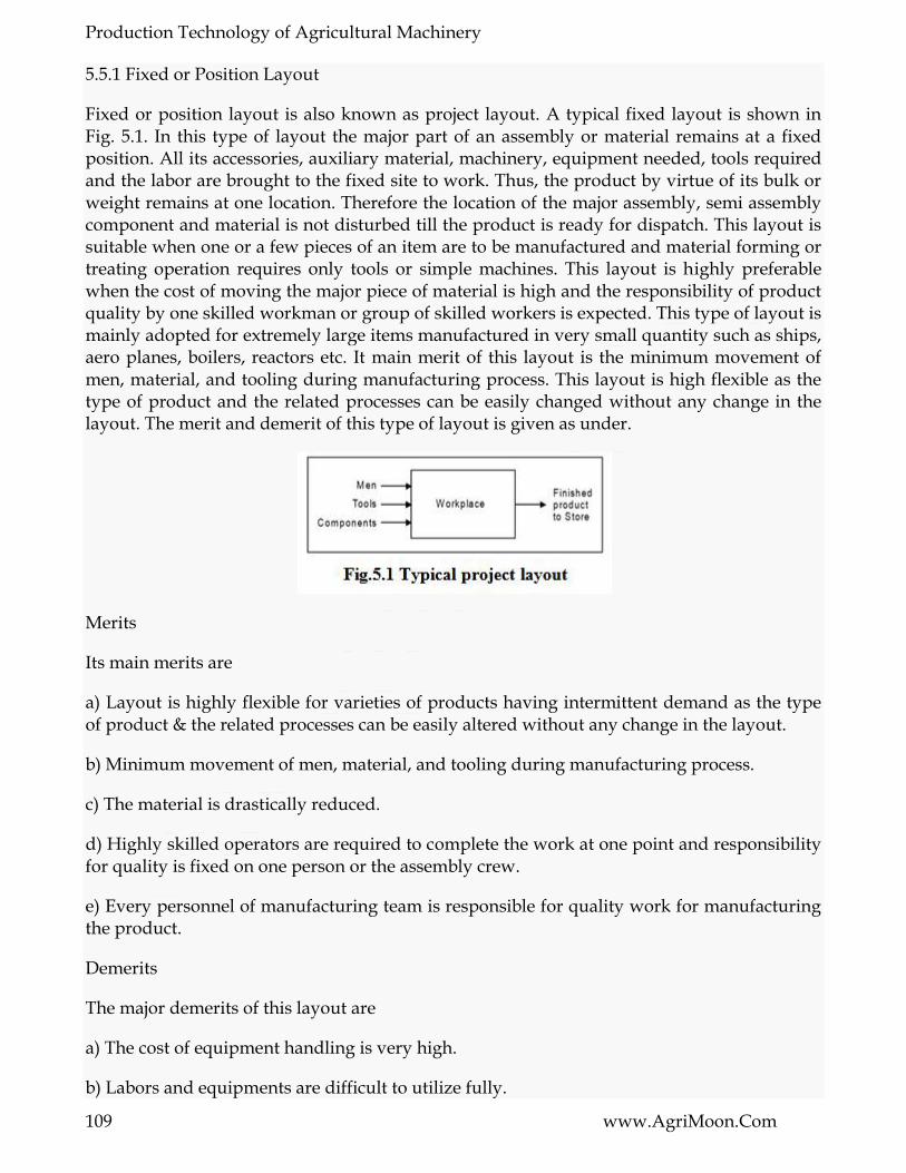
Production Technology of Agricultural Machinery
109 www.AgriMoon.Com
5.5.1 Fixed or Position Layout
Fixed or position layout is also known as project layout. A typical fixed layout is shown in Fig. 5.1. In this type of layout the major part of an assembly or material remains at a fixed position. All its accessories, auxiliary material, machinery, equipment needed, tools required and the labor are brought to the fixed site to work. Thus, the product by virtue of its bulk or weight remains at one location. Therefore the location of the major assembly, semi assembly component and material is not disturbed till the product is ready for dispatch. This layout is suitable when one or a few pieces of an item are to be manufactured and material forming or treating operation requires only tools or simple machines. This layout is highly preferable when the cost of moving the major piece of material is high and the responsibility of product quality by one skilled workman or group of skilled workers is expected. This type of layout is mainly adopted for extremely large items manufactured in very small quantity such as ships, aero planes, boilers, reactors etc. It main merit of this layout is the minimum movement of men, material, and tooling during manufacturing process. This layout is high flexible as the type of product and the related processes can be easily changed without any change in the layout. The merit and demerit of this type of layout is given as under.
Merits
Its main merits are
a) Layout is highly flexible for varieties of products having intermittent demand as the type of product & the related processes can be easily altered without any change in the layout.
b) Minimum movement of men, material, and tooling during manufacturing process.
c) The material is drastically reduced.
d) Highly skilled operators are required to complete the work at one point and responsibility for quality is fixed on one person or the assembly crew.
e) Every personnel of manufacturing team is responsible for quality work for manufacturing the product.
Demerits
The major demerits of this layout are
a) The cost of equipment handling is very high.
b) Labors and equipments are difficult to utilize fully.

Production Technology of Agricultural Machinery
110 www.AgriMoon.Com
c) It is limited to large items only. Applications This type of layout is mostly adopted for extremely large items manufactured in very small quantity such as ships, aero planes, aircraft, locomotive, ship assembly shops, shipyards, boilers, reactors etc.
5.6 Process or Functional Layout
A typical process or functional layout is shown in Fig. 5.2. In this type of layout arrangements of similar machines, production facilities and manufacturing operations are grouped together according to their functions. Machine tools of one kind are positioned together so that all the similar operations are performed always at the same place e.g. all the lathes may be grouped together for all kinds of turning and threading operations, all drilling machines in one area for carrying out drilling work, all tapping machines in one area for carrying out tapping work, all milling machines in one area for carrying out milling work all buffing and polishing machines at one place for carrying out surface finishing work, and so on. This type of layout is normally preferred for the industries involved in job order type of production and manufacturing and/or maintenance activities of non- repetitive type. This layout needs not to have to be changed every time of the product or component changes. Also the breakdown of any machine does not affect the production. This type of layout is highly suitable for batch production.
Merits
The major merits of this layout are: There exists a wide flexibility regarding allotment of work to equipment and workers.
1. There is a better utilization of the available equipment.
2. Comparatively less numbers of machines are needed in this layout and hence thus reducing capital investment.
3. There is an improved product quality, because the supervisors and workers attend to one type of machines and operations.
4. Varieties of jobs coming as different job orders thus make the work more interesting for the workers.

Production Technology of Agricultural Machinery
111 www.AgriMoon.Com
5. Workers in one section are not affected by the nature of the operations carried out in another section. For example, a lathe operator is not affected by the rays of the welding as the two sections are quite separate.
Demerits
The major demerits of this layout are :
1) This layout requires more space in comparison to line or product layout for the same amount of production.
2) Production control becomes relatively difficult in this layout.
3) Raw material has to travel more which increases material handling and the associated costs.
4) This layout requires more efficient co-ordination and inspections.
5) Increased material handling cost due to more movement of process raw material to various paths
6) More material in process remains in queue for further operations.
7) Requires large in-process inventory.
8) Completion of same product takes more time.
Application
This layout is used for batch or moderate production.
It specify path for group technology.
Line or Product Layout A typical line or product layout is shown in Fig. 5.3. This layout implies that various operations on raw material are performed in a sequence and the machines are placed along the product flow line, i.e., machines are arranged in the sequence in which the raw material will be operated upon. In this type of layout all the machines are placed in a line according to the sequence of operations, i.e., each following machine or section is arranged to perform the next operation to that performed by its preceding machine or section. In this layout raw material starts from one end of production lines and moves from one machine to next along a sequential path. Line layout is advantages in the continuous- production system where the number of end products is small and the parts are highly standardized and interchangeable. It is suitable for products having steady demand. This layout may have operational sequence namely forging, turning, drilling, milling, grinding and inspection before the product is sent to the finished goods store for packing and shipment. This layout is used for mass production and ensures smooth flow of materials and reduced material handling. Breakdown of any machine in the line in this layout may result in even stoppage of production.

Production Technology of Agricultural Machinery
112 www.AgriMoon.Com
Merits
Its main merits are
1. It involves smooth and continuous work flow.
2. It may require less skilled workers
3. It helps in reducing inventory.
4. Production time is reduced in this layout.
5. Better coordination, simple production planning and control are achieved in this layout.
6. For the same amount of production, less space requirements for this layout.
7. Overall processing time of product is very less.
8. This layout involves automatic material handling, lesser material movements and hence leads to minimum possible cost of manufacturing.
Demerits The major demerits of this layout as compared with process layout are—
1) It is very difficult to increase production beyond the capacities of the production lines.
2) When single inspector has to look after many machines, inspection becomes difficult
3) This layout is very less flexible for product change.
4) The rate or pace rate of working depends upon the output rate of the slowest machine and hence leading to excessive idle time for other machines if the production line is not adequately balanced.
5) Machines being put up along the line, more machines of each type have to be installed for keeping a few as stand by, because if on machine in the line fails, it may lead to shut down of the complete production line. That is why the line or product layout involves heavy capital investments.
Applications It is used in assembly work. Combination Layout:

Production Technology of Agricultural Machinery
113 www.AgriMoon.Com
Fig. 5.4 shows a typical combination type of layout for manufacturing different sizes of crank shafts. It is also known as group layout. A combination of process and product layouts combines the advantages of both types of layouts. Most of the manufacturing sections are arranged in process layout with manufacturing lines occurring here and there scattered wherever the conditions permit. These days, the most of manufacturing industries have adopted this kind of layout. In this type of layout, a set of machinery or equipment is grouped together in a section, and so on, so that each set or group of machines or equipment is used to perform similar operation s to produce a family of components. A combination layout is possible where an item is being made in different types and sizes. In such cases, machinery and manufacturing equipments are arranged in a process layout but a group of number of similar machines is then arranged in a sequence to manufacture various types and sizes of products. In this layout, it is noted that, no matter the product varies in size and type, the sequence of operations remain same or similar. This layout is suitable when similar activities are performed together thereby avoiding wasteful time in changing from one unrelated activity to the next. It focuses on avoiding unnecessary duplication of an effort. It is preferable for storing and retrieving information changing related to recurring problems thereby reducing the search tin understanding information and eliminating the need to solve the problem again. It is also useful when a number of items are produced in same sequence but none of the items are to be produced in bulk and thus no item justifies for an individual and independent production line. There are some merits, demerits and application of this layout which are given as under:
Merits
The merits of this type of layout are:
1) Reduction in cost of machine set-up time and material handling of metals.
2) Elimination of excess work-in-process inventory which subsequently allows the reduction in lot size.
3) Simplification of production planning functions, etc.

Production Technology of Agricultural Machinery
114 www.AgriMoon.Com
Demerits
The major demerits of this layout are :
1) Change of the existing layout is time consuming and costly.
2) Inclusion of new components in the existing component requires thorough analysis.
3) Change of input component mix may likely to change complete layout structure.
4) Change of batch size may change number of machines.
Application
Manufacturing circular metal saws, hacksaw, wooden saw, files and crank shaft. Comparison of Line or Product Layout and Process or Functional Layout Comparison of line or product layout and process or functional layout is given in Table 5.1.

Production Technology of Agricultural Machinery
115 www.AgriMoon.Com
LESSON 16. QUALITY MANAGEMENT
6.1. Quality is a natural phenomenon
6.1.1 Change is inevitable
Change is the law of nature. Time is always in motion. Time brings change. The direction of change is decided by exerted effort. If no effort applied, the change is always towards decay. Growth is result of efforts done by all in right direction, continuously and positively. Growth is the total sum of all improvements done towards betterment. Thus growth is directed towards enriched life. When growth stops decay begins.
6.1.2 Nature does not accept poor quality
Nature is a museum of variety. There are numerous varieties of species. All natural products, plats and all the population of animal kingdom suffer changes. The law of survival of fittest operates. Only those, who are capable of countering the odds of environment, survive. Those, who develop the skills of exploiting the support of Mother Nature, grow. Thus , nature also permits appropriate quality to grow. Quality is a measure of excellence. Excellence also demands effort. Therefore growth and excellence go hand in hand. The species not fit to fulfil the requirements; get extinct i.e. poor quality is not acceptable to the nature as well.
6.2 What is quality
To a common man, quality is acceptability of functional performance, realibility and an offer of enhanced facilities at the same cost. To a manufacturer the quality means compliance to the set specifications. The achievement of features and characteristics as demanded by specifications will be the scope of quality for production shop in charge. A designer‘s point of view will test the capabilities of specifications as per national or international standards. Here, ‘Quality Level‘ and ‗Quality Grade‘ may be understood properly. Can you say a color TV is a better quality TV than a black and white? No, both are having different quality grades as have been built to different specifications. Level of quality may be compared for various products made as per the same or similar specification. In past years it was understood that quality is the characteristic of a product. The manufacturer was considered to be the creator of the product and provision of any or many characteristics was his prerogative. In the days of shortages and in suppliers market this attitude of a manufacturer was accepted. Now the situation has undergone a total change. The consumer has access to the entire world‘s market. The customer can pick and choose. In this age of cutthroat competition, the customer has assumed a controlling role. Now, the supplier has to satisfy the customer compulsorily.
Today, quality has assumed a market-oriented trent. Quality is defined as ―fitness to use‖. Who will ascertain the fitness to use? Obviously the customer or the end user.
The concept of quality has been explained differently. Commonly quality is understood as conformance with requirements. It is usual to consider the ―requirements‖ as those of the

Production Technology of Agricultural Machinery
116 www.AgriMoon.Com
―customer‖. Requirements may be specified in a contract, purchase specification, product literature or in legislation. An accepted definition of quality is:
―Quality is the totality of features and characteristics of a product or service that bear on its ability to satisfy stated, statuary or implied needs‖
Here ‗product‘ may include hardware, processed material, software or a combination thereof. A product can be tangible (e.g. assemblies or processed materials) or intangible (e.g. knowledge or concepts), or a combination thereof.
6.3 The new concept and role of quality
The concept of quality has undergone change. The conventional concepts attached to quality were very different from the present concepts, which are entrusted on quality in prevailing environment.
The conventional concept considered quality as a line function for inspectors only, working under guidance of experts. Thus quality function was not considered as a voice of management and others enjoyed credit for success of this function. New concept considers quality as management function and quality is considered to be everybody‘s job performed under management leadership.
In conventional concept high grade of quality was considered to be the aim, now we strive for proper grade. Today attainment of a quality grade is supposed to be a strategic requirement demanding a planned action to achieve, what has been designed. Joseph M Juran believes that, ‗Quality does not happen by accident, it must be planned‘. This is contrary to the belief that quality grade achievement is only a technical task, which will be automatically achieved through the laid out specifications.
As per the conventional concept the quality was considered a characteristic of product. Consequently, inspection was supposed to be a burden on the company. Now we understand that quality is a function and characteristics of an organisation. Factually, product from a organisation will be quality product. The fact remains – ―quality can be produced and cannot be controlled‖
6.4 Quality develops with industrial growth
6.4.1 Quality grows naturally as per industrial needs
Industrial growth has taken place for fulfilling the requirements of the society. As and when society developed some need, people came forward with innovative and indigenous solutions to the problems. Society also rewarded such industrious people suitably. Therefore motivation for doing the things in a better way, survived. Consequently the industrial growth and developments in associated fields were also continued.
The above referred need was the source for desire for creativity. ―Need is the mother of invention‖. Competition has also played a major role in built up of human behaviour. That is why ―war‖ has always presented a necessary environment suitable for inventions and

Production Technology of Agricultural Machinery
117 www.AgriMoon.Com
industrial growth. Need was urgently manifested by war and competition was created due to conflicts which used to be the basic causes of war.
6.4.2 Quality: A sequential and chronological development
With time industrial growth has taken place. Primitive man worked with hand tools. With the developments in the field, general-purpose machines came into use. These machines were capable of manufacturing small items in singles. At this technological status, the requirements were also simple. The necessary quality requirement was only the possibility of assembly. So inspection was also done to suit the assembly requirements. If assembled, the component was deemed as correct, else will need rework or rejection.
6.4.3 Quality through dimensional checks
Further, there came multi-tool holding machines e.g. Turret lathes which permitted more machining operations in one setting. Such machines saved on setting time and proved to be better productive. Inspection also improved to cope with faster technology. To make the mating part independent, inspection was done with measuring instruments. Checking was done as per the drawing dimensions that used to be tolerated to ensure interchange ability.
6.4.4 Quality focus on process
When demands for still faster production levels were felt, people built special purpose machines. These machines were specifically developed for enhanced production. Machines were designed for a specific purpose. For example, a machine designed to machine automobile pistons should be able to do those very operations, which are required for manufacture of automobile pistons. Obviously the speed of operations will be much fast as compared to that could be attained by general purpose machines.
The special purpose machines were integrated to develop automatic workstations. A continuous production of components was possible with the help of such facility. Parallel developments in field of electronics, meteorology, materials and tooling enhanced the production rate many folds.
The fast and continuous manufacture was a challenge to the inspection experts also. The time needed to measure the produce was much more than actual production time. Further, the prevailing inspection procedures were not luscious as they indicated as if a group of critics is there to approve the production of a worker, and results of their investigations will bring him reward or punishment. Also, there are some products which cannot be tested unless destroyed e.g. shaving blades or bullets which if used will be wasted. The solution was found through the concepts of ‗quality control‘. Quality control shifted its focus from product to the process. Inspection had its total concentration on the product. Inspection only evaluated the product as good or bad. Inspection was like if you select out the rotten tomatoes from a basket. Quality control will count out rotten ones and results will be used to suggest the right pesticide so that next pick will have lower rate of bad pieces. To accomplish this task quail.

Production Technology of Agricultural Machinery
118 www.AgriMoon.Com
6.4.5 Inception of system approach in quality
The developments in field of productions technology continued further. Use of more sophisticated electronics and computers continued and numerically controlled machines and computerized numerically controlled machines made continuous manufacturing process possible. Today we have further developments available to us like Robotics, Automation, and Artificial Intelligence, which have made more complex technologies available to us. Transfer line manufacturing and flexible manufacturing are few examples to illustrate.
With this level of technological support available to us, operation of an organisation provides much different challenges for managers to face. Today the problems of ‗How to do?‘ nature in technological fields, usually have readymade answers. Now the focus is more on ‗why to do?‘ or ‗who shall do‘. The emphasis is more on strategically and human resource issues.
In this age of high-tech operations, if we extend our imagination it is possible to conceive of a factory, where automatically the raw material is picked up, processed, packed and dispatched. In such an organisation, the quality of output will depend on only, if the raw material is within specification, the machine computer is rightly set; all machines are properly maintained and so on. This means that quality of output basically depends on the compliance of systems and procedures.
The importance of systems and procedures was also appreciated during the development of quality systems and procedures. Quality control techniques were very useful and were largely adopted by industries and procedures. Quality control techniques were very useful and were largely adopted by industries and organisations. The basic approach was postoperative. The clues for corrections and improvements were received from the failures. Quality assurance concept came as solution to this need. The quality assurance systems are quality control applied in planning stage. The experts could draw ‗quality assurance plans‘ in advance. This was an assurance to the customer that with these measures compiled with, the quality resets assured. The total success of a quality assurance plan consequently that of quality assurance system depended on the thorough compliance of quality assurance plan.
6.4.6 Quality conformance through 2nd/3rd partly inspection
For enhanced customer confidence, quality assurance plan often included the customer checkpoints. Wherever, if the customer could afford to depute their people for such QA checks, supplier and customer mutually accepted the quality level. Quality assurance thus practiced was effective to good extent. This had some practical difficulties. Calling of a customer from a geographically distant location was costly and sometimes not practically feasible. This problem was taken care by the provision of quality surveillance concept. The quality surveillance group was constituted by the supplier deploying his in depended people. They were held responsible for ensuring implementation of quality assurance plans, as if working on behalf of the customer .these type of checks were either project dependent or periodical .obviously no system could work economically which demanded cent per cent checks. This could be taken care through quality audits Quality audits are designed to ensure that quality systems are properly.

Production Technology of Agricultural Machinery
119 www.AgriMoon.Com
As we have seen above, the quality has developed along with technological and industrial growth .The implementation of quality principles has grown along with the technology and industrial. Japan has show a role model in implementation of quality models. They implemented the quality principle very sincerely in their systems. They proved the efficacy of these principles. Japan was sarcastically referred for quality during the period of Second World War. After three decades or so they became example of quality workman ship. Their quality system were effectively set. The European quality model of ISO 9000 was never a challenge for them. They are perceived to be already ahead in quality implementation than that demanded by these systems.
6.5 ISO 9000: Wider quality coverage
ISO 9000 brought grace to the quality function by legitimizing the broadened scope of quality. Quality earned a reputation of being a management technique rather than a subdued function. ISO 9000 encompassed all necessary activities of an organisation, ensured written procedures and compelled to maintain proof of working to the procedures. It demanded documented ‗Quality policy‘ and earmarked responsibilities along with entrusted authorities. It laid a great emphasis on defined quality systems. All the elements are possibly brought into the purview of measurements. The management principle ‗You can manage only what you can measure‘ holds good. The coverage was broad enough to include the chief executive and up to lowest worker. Focus was, however , on aspects directly affecting the quality. The premise of ‗directly affecting quality‘ could not cover some vital aspects like costs that have been incurred for quality attainment, requirements of welfare of employees, direct concern for environment and society.
Philip B Crosby four absolutes of quality:
The Definition: Conformance with requirement The System : Prevention not cure The measure : The cost of quality The Target : Zero defect-Right first time
The measure of quality i.e. the cost of quality has been left to be a concern of the organisation. The cost of quality is factually the cost of bad quality and includes all rejections and reworks in the plant and at the customer‘s place.
6.6 The total quality culture
Studies revealed that all the organisations, those reached at the top performer level did not necessarily sustain their position. This reveals that earning profit and sustaining and maintaining growth need different measures. Experience showed that certain excellence criterion developed for excellence awards for performance of industries were including the necessary elements. Deming award and Malcolm Baldrrige award criteria showed that strength. The winner companies of Deming prize sustained their profitability while other companies were highly susceptible to external influence. Such criterion were considered for implementation of total quality management. The boost given by ISO 9000 proved a right step towards the Total Quality management culture. TQM was developing spontaneously in the industrial climate.

Production Technology of Agricultural Machinery
120 www.AgriMoon.Com
The total quality management principles involve the management approach of an organisation, aiming at long-term success. The approach is cantered on quality. The management shall be based on participation of all its members. The long term success will be attained through customer satisfaction, benefits to all members of organisation and benefit to society.
The various criterion selected for TQM model are divided into two sections. The business results are, however, most important for an organisation. Results are extracted due to people satisfaction, customer satisfaction and impact on society.
The business results are outcome of processes. Here TQM covers all the processes irrespective of their effect on quality. All the activities are part of TQM as it is total management. The processes function properly by optimum utilisation of resources. This basically is made possible by people management using right policies strategies. All the effective management is possible by right leadership.
The dimensions discussed above are to be managed effectively for total quality management culture. The concept is mainly dependant on continuous improvements. Many of the total quality dimensions are already being used by organisations. The comprehensiveness of concepts lie in application in totality. The ‗Divine Discontent‘ is the intrinsic need of the organisation for improvement. First comparison could be with own past performance. Then bench marking will provide guidance for improvements. ‗Customer satisfaction‘ may not be sufficient in today‘s competitive environment, and therefore we have to strive for ‗Customer delight‘.
The role of industry in society has also assumed a change. Today we do not see an organisation as profit generating unit only. Society expects some special obligations to be fulfilled. An organisation cannot grow if their intentions regarding social responsibilities are not fair. One may not be allowed to earn profits at the cost of public comforts. Pollution, noise, environment unfriendly activities if not controlled by state, these will be controlled by society through the media. Therefore the growth of industry continues if acceptance from the society is available. This has become a new dimension in growth of quality. The quality organisations, which plan to survive long and which plan to grow cannot afford to skip this important aspect of quality. This is not a measure of product quality but a characteristic which a quality organisation must possess and protect.
6.7 Conclusion
The world of today is very comfortable to survive. The world of today is very difficult to live. Maintaining existence is cumbersome. Everybody is aware. Information is readily available to all. Competition is global. The only route to success is to become excellent. Top performances grow. Indian market is also open to entire world. In such economic environment, growth can be guaranteed to ace performers only.
When market is open to a customer, the only way to win him on quality front is by providing ―Customer delight‖ at comparably lower price. This could be accomplished only if the organisation has exploited every possible productivity enhancement measures. The other aspects could be selection of optimum strategies. This all may be possible if human resources

Production Technology of Agricultural Machinery
121 www.AgriMoon.Com
are kept satisfied and environment is kept conducive for motivation. Their skills and knowledge kept up-to-date.
My point formula for growth in present environment is to achieve on the five fronts of Quality, Strategy, Productivity, Market price and Human resource management.
As we have seen above quality has always moved along with growth. It will be accompanying the growth in future also. We see no opportunities in the present scenario for poor quality. Quality is the order of the day and we have to maintain it.

Production Technology of Agricultural Machinery
122 www.AgriMoon.Com
MODULE 6. Economics of process
LESSON 17. ECONOMICS OF PROCESS SELECTION
1.1 Introduction
Design engineers, manufacturing engineers, and industrial engineers, in analyzing alternative methods for producing a part or a product or for performing an individual operation or an entire process, are faced with cost variables that relate to materials, direct labor, indirect labor, special tooling, perishable tools and supplies, utilities, and invested capital. The interrelationship of these variables can be considerable, and therefore, a comparison of alternatives must be detailed and complete to assess properly their full impact on total unit costs.
1.2 Materials
The unit cost of materials is an important factor when the methods being compared involve the use of different amounts or different forms of several materials. For example, the materials cost of a die-cast aluminum part probably will be greater than that of a sand-cast iron part for the same application. An engineering plastic for the part may carry a still higher cost. Powder-metal processes use a smaller quantity of higher-cost materials than casting and machining processes. In addition, yield and scrap losses may influence materials cost significantly.
1.3 Direct Labor
Direct labor unit costs essentially are determined by three factors: the manufacturing process itself, the design of the part or product, and the productivity of the employees operating the process or performing the work. In general, the more complex the design, the closer the dimensional tolerances, the higher the finish requirements, and the less tooling involved, the greater the direct labor content will be.
The number of manufacturing operations required to complete a part probably is the greatest single determinant of direct labor cost. Each operation involves a ―pick up and locate‖ and a ―remove and set aside‖ of the material or part, and usually additional inspection by the operators is necessary. In addition, as the number of operations increases, indirect costs tend to accelerate. The chances for cumulative dimensional error are increased owing to changing locating points and surfaces. More setups are required; scrap and rework increase; timekeeping, counting, and paperwork expand; and shop scheduling becomes more complex.
Typical of low-labor-content processes are metal stamping and drawing, die casting, injection molding, single-spindle and multispindle automatic machining, numerical and computer-

Production Technology of Agricultural Machinery
123 www.AgriMoon.Com
controlled drilling, and special-purpose machining, processing, and packaging in which secondary work can be limited to one or two operations. Semiautomatic and automatic machines of these types also offer opportunities for multiple-machine assignments to operators and for performing secondary operations internal to the power-machine time. Both can reduce unit direct labor costs significantly. Processes such as conventional machining, investment casting, and mechanical assembly including adjustment and calibration tend to contain high direct labor content.
1.4 Indirect Labor
Setup, inspection, material handling, tool sharpening and repairing, and machine and equipment maintenance labor often are significant elements in evaluating the cost of alternative methods and production designs. The advantages of high-impact forgings may be offset partially by the extra indirect labor required to maintain the forging dies and presses in proper working condition. Setup becomes an important consideration at lower levels of production. For example, it may be more economical to use a method with less setup time even though the direct labor cost per unit is increased. Take a screw-machine type of part with an annual production quantity of 200 pieces. At this volume, the part would be more economically produced on a turret lathe than on an automatic screw machine. It‘s the total unit cost that is important.
1.5 Special Tooling
Special fixtures, jigs, dies, molds, patterns, gauges, and test equipment can be a major cost factor when new parts and new products or major changes in existing parts and products are put into production. The amortized unit tooling cost should be used in making comparisons. This is so because the unit tooling cost, limited by life expectancy or obsolescence, is very production-volume-dependent. With high production volume, a substantial investment in tools normally can be readily justified by the reduction in direct labor unit cost, since the total tooling cost amortized over many units of product results in a low tooling cost per unit. For low-volume-production applications, even moderate tooling costs can contribute relatively high unit tooling costs.
In general, it is conservative to amortize tooling over the first 3 years of production. Competition and progress demand improvements in product design and manufacturing methods within this time span. In the case of styled items, the period may need to be shortened to 1 or 2 years. Automobile grilles are a good example of items that traditionally have had a production life of two years, after which a restyled design is introduced.
1.6 Perishable Tools and Supplies
In most cost systems, the cost of perishable tools such as tool bits, milling cutters, grinding wheels, files, drills, taps, and reamers and supplies such as emery paper, solvents, lubricants, cleaning fluids, salts, powders, hand rags, masking tape, and buffing compounds are allocated as part of a cost-center manufacturing-overhead rate applied to direct labor. It may be, however, that there are significant differences in the use of such items in one process when compared with another. If so, the direct cost of the items on a unit basis should be included in the unit-cost comparison. Investment casting, painting, welding, and abrasive-

Production Technology of Agricultural Machinery
124 www.AgriMoon.Com
belt machining are examples of processes with high costs for supplies. In the case of cutoff operations, it is more correct to consider the tool cost per cut as an element in a comparison. Cutting-tool costs for other types of machining operations also may constitute a major part of the total unit cost. The high cost and short tool life of carbide milling cutters for profile milling of ―hard metals,‖ such as are used in jet-engine components, contribute significantly to the cost per unit. The hard metals include Inconel, refractory-metal alloys, and superalloy steels.
1.7 Utilities
Here again, as with perishable tools and supplies, the cost of electric power, gas, steam, refrigeration, heat, water, and compressed air should be considered specifically when there are substantial differences in their use by the alternative methods and equipment being compared. For example, electric power consumption is a major element of cost in using electric arc furnaces for producing steel castings. And some air operated transfer devices may increase the use of compressed air to a point at which additional compressor capacity is needed. If so, this cost should be factored into the unit cost of the process.
1.8 Invested Capital
Obviously, it is easier and less risky for a company to embark on a program or a new product that utilizes an extension of existing facilities. In addition, the capital investment in a new product can be minimized if the product can be made by using available capacity of installed processes. Thus the availability of plant, machines, equipment, and support facilities should be taken into consideration as well as the capital investment required for other alternatives. In fact, if sufficient productive capacity is available, no investment may be required for capital items in undertaking the production of a new part or product with existing processes. Similarly, if reliable vendors are available, subcontracting may be an alternative. In this event, the capital outlays may be borne by the vendors and therefore need not be considered as separate items in the cost evaluation. Presumably, such costs would be included in the subcontract prices per unit.
On the other hand, there may be occasions when the production of a single component necessitates not only the purchase of additional production equipment but also added floor space, support facilities, and possibly land. This eventuality could occur if the present plant was for the most part operating near capacity with respect to equipment, space, and property or if existing facilities were not fully compatible with producing the component or product at a low unit cost.
When capital equipment costs are pertinent to the selection of a process, the unit cost calculations should assign to each unit of product its share of the capital investment based on the expected life and production from the capital item. For example, a die-casting machine that sells for $200,000, has an estimated production life of 10 years and an expected operating schedule of three shifts of 2000 h each per year, and is capable of producing at the rate of 100 shots per hour with a two-cavity mold, less a 20 percent allowance for downtime for machine and die maintenance and setups, would have a capital cost per unit as follows:
$200,000

Production Technology of Agricultural Machinery
125 www.AgriMoon.Com
Capital cost = ---------------------------------------- = $ 0.020 per piece
10x3x2000 x100x2 (100%-20%)
This calculation assumes that the machine will be utilized fully by the proposed product or other production. Also, the computation does not include any interest costs. Interest charges for financing the purchase of the machine should be added to the purchase price. If interest costs of $50,000 over the life of the machine are assumed, the capital cost per unit would be $0.025 instead of $0.020. This type of calculation is applicable solely to provide a basis for choosing between process alternatives and is simpler and different from the analysis involved in justifying the investment once the process selection has been made.
1.9 Other Factors
Occasionally, a special characteristic of one or several of the processes under consideration involves an item of cost that may warrant inclusion in the unit-cost comparison. Examples of this type might include costs related to packaging, shipping, service and unusual maintenance, and rework and scrap allowances. The important point is to recognize all the essential differences between the alternatives and to allow properly for these differences in the unit-cost comparison. Remember that the objective is to determine the most economical process for a given set of conditions, i.e., the process that can be expected to produce the part or product at the lowest total unit cost for the anticipated sales volume.
Also, in making a unit-cost comparison between several alternatives, it is necessary to include in the analysis only those costs which differ between alternatives. For example, if all choices involve the same kind and amount of material, the materials cost per unit need not be included in the comparison.
Further, when available capacity exists on production equipment used for similar components, the choice of process may be obvious. This is especially true when the production quantity for the new part or product is not high. The opportunity for utilizing available capacity makes an additional investment in an alternative process difficult to justify
TYPICAL EXAMPLES
Exhibits 1.1 and 1.2 are examples showing a concise layout for comparing alternatives. Exhibit 1.1 compares sand mold casting with die casting for one part. Exhibit 1.2 considers making a part on a turret lathe versus single spindle and multi spindle automatic screw machines. Neither of these examples attempts to justify the purchase of machines or equipment. These examples assume that the processes are installed and have available capacity for additional production. Note that the production quantity is an important factor in determining the most economical process. In both illustrations, as the production quantity increases, the unit cost comparison begins to favor a different alternative.
EXHIBIT 1.1 Sand-Mold Casting versus Die Casting
Part: New model pump housing Annual quantity: 10,000 pieces
Expected product life: 5 years Normal lot size: 2500 pieces

Production Technology of Agricultural Machinery
126 www.AgriMoon.Com
EXHIBIT 1.2 Turret Lathe versus Single-Spindle and Multi spindle Automatic Screw Machines (Excluding Secondary Operations)
Part: High-pressure hose fitting Annual quantity: 500 pieces
Expected product life: 2 years Normal lot size: 500 pieces

Production Technology of Agricultural Machinery
127 www.AgriMoon.Com
MODULE 7. Techno economic feasibility of project report
LESSON 18. TECHNO ECONOMIC FEASIBILITY OF PROJECT REPORT
1.0 Introduction
As a prospective entrepreneur , you are required to decide at the outset the product that you have to manufacture .If you decide to get into service sector , you must decide the type of ‗service activity‘ for your venture. Having made such a decision tentatively, you must answer certain questions before you spend time and resources required to make a detailed study of project for getting financial assistance. The question that you make to answer are:
1.1 What is a preliminary project report?
Preliminary project report, in short PPR, is simple brief data – sheet that gives you an insight into the following:
(i) How much money, man-power & material would be required to setup project?
(ii) What type of machines would be required?
(iii) What are sources of technology that would be required? And
(iv) What would be the economic gains from the project?
In short, PPR is a brief outline of the project that tells you quickly about the viability of the project, so as to help you decide whether it is pursuing further or not.
1.2 Why preliminary project report?
At the stage of preparing a PPR you may have in mind not just one venture/product, but 3 or 4 ideas to choose from. Since it calls for considerable time and resources to prepare a Detailed Project Report (DPR) it would not be advisable to prepare a DR for every product ideas that may be floating in your mind.
Even if you could prepare DPR for all the product ideas that you have in mind, the time required to do so would be so much that it would make the first DPR obsolete or outdated by the time you complete all DPRs.
Further, the money, time and information required to prepare DPRs for all the product ideas that you have in mind only to examine their viability may make the very exercise of DPR preparation unviable. This does not mean that PPR can substitute a DPR. It only means that is desirable to prepare a PPR prior to spending resources on preparation of a DPR.
Production Technology of Agricultural Machinery
128 www.AgriMoon.Com
i. You get enough data quickly to fill up the required for provisional registration of your unit with the stage government. It is a must before commencing various times consuming formalities connected with planning and setting up of a small-scale unit.
ii. The data you get from PPR will help you in completing certain formalities in anticipation of setting up a project. For example, if you want to set up an electronic unit, you have to your production programme approved from the concerned State/Central Government department. For this you have to supply data about the projected production level and raw-material requirement, which you could get from PPR.
iii. The data collected by preparing a PPR forms a good take-off point for preparing a DPR when you desire to do so.
iv. It will help you identify in advance the infrastructural requirement for your project and sound the concerned government agencies accordingly so that you can get necessary facilities such as land / shed at the right time.
v. Finally, the major contribution of a PPR at the nascent stage of your entrepreneurial career is that it instils confidence in you and motivates you to stare the time-consuming process of data collection and preparation of a DPR.
1.3 How to prepare a PPR?
To help you prepare a PPR systematically, a proforma is adjoined to this section at Annexure-l. A quick perusal of the poform will indicate that the information called for could be collected and presented quickly as well as systematically.
Let us now see how best one can prepare a PPR as pre the enclosed proforma .Let us precede point-to-point as it appears in the proforma.
a) In this section titled ‗General‘ there is an item ‗location‘. You may not be in the position to pinpoint the exact location, but then, you should indicate the city/industrial estate where u wants to set up the unit. What is important is geographical area, is appropriate after taking into account the availability of raw-material, labour, marketing etc. and the cost involved in transportation of raw-material/finished goods if they are freight sensitive. Further, you will have to indicate whether you will be setting up the unit in rented premises or in the industrial area or in a place owned by you. This information will help you adviser/counsellor in identifying your requirement of land/shed so as to make certain advance arrangement with concerned agency that provides land/shed.
b) The information called for under this point pertain to your educational qualification, experience etc. These are readily available and therefore, can be presented easily. This information will help the adviser to understand whether the project proposition vis-a-vis the background is likely to be acceptable to the institutions.
c) This point deals with various details of the proposed project in terms of raw-material requirement, production programme etc. Here, you may be required to move around and collect the information since you will not be having it readily. For example, more than not, you may not know the specification or even the names of the machinery you need. In such a

Production Technology of Agricultural Machinery
129 www.AgriMoon.Com
case, you must approach you adviser/other knowledgeable persons ask them for their guidance on the sources for getting the necessary information.
You may refer to ready –made project profiles available with the trainer or District Industries Centre or any good library .You can even approach people trading in the product and get information from them. You may visit one or more existing units manufacturing the same product that you need. Though difficult, it is the best source of collecting information that you need.3
The manufactures/suppliers of machinery can also give quite a good amount of information. A chat with the consultant of the State Technical Consultancy Organisation (there are 17 such organisations in the country) could prove fruitful.
In sort, what is important you should identify the sources of information and get into action at the first instance to collect necessary information. You can utilise the time devoted for market survey for collecting such information. You need to keep in mind certain points while connecting and presenting such information pertaining to point No.2 as noted below.
d) While listing down the machinery, care has to be taken to indicate the power requirement. This could be useful for further calculations. While arriving at the total cost of the machinery, you have to take into account the cost of transportation, sales tax, insurance, handing charges etc. In short, you have to consider the ‗landed cost‘ i.e. cost of machinery plus all other expanses till reach the factory site.
e) At this stage, it is not necessary in detail each component of the landed cost of the machinery. What can be done depending on the nature of the machinery and sources of supply, rough estimates in terms of 20% or so of the quoted price of the machinery can be made and added to the total cost of the machinery. Any extra charges for installation/erection of the machinery must also form a part of the cost under this head.
f) Here, the items that you propose to manufacture and the quantity to be produced in a year must be indicated. The moment you have a list of machinery, you can calculate the quantity of goods that can be produced in a year based on the capacity f machinery. Further, while indicating production for the year,
It is not advisable to assume that you shall be able to produce 100% of what the machinery can produce at its maximum capacity in a year.
Suppose a machine can produce 100 kgs of an item per day (8 hrs.), it would be wrong to assume that the annual production would be 30,000 kgs, (we normally calculate annual production on the basis working days in a year). It is so because that in a given year, the machinery may break down calling for repairs and consequently, calling for a shut-down or there may be power-cuts or raw-material shortage. Thus, considering such eventualities the total quantity to be produced in a year may be calculated, as a thumb-rule at 70% or 80% or so the equipment capacity.
Col.No.4 of Item 2.2 in the proforma deals with sales revenue which can be calculated by multiplying the annual production with the selling price per unit. While deciding the selling price, there is no need to go into details of product cost at this stage. What you have to do is

Production Technology of Agricultural Machinery
130 www.AgriMoon.Com
to look at the market price of the product which you intend to manufacture and deduct any commission or discount at the retailer and whole-sales level so that you can get an idea of ex-factory price.
g) This point deals with details on raw-materials. You are required to indicate item-wise requirement of raw-materials in terms of quantity and value. Further, the sources of procurement of these raw-materials i.e. places from where you intend to buy these materials should be indicated. This exercise will help you in indentifying where the raw materials would be easily available and whether it is necessary for you procure raw-materials form far-off places. While giving the list of raw-materials required for production, raw-materials required for packing, materials/stores required for maintenance of machinery (for example, grease, cotton waste etc.)And those materials required for testing (for example, chemical used for testing if tour unit needs a testing laboratory).
h) Under this head ‗Utilities‘, those inputs that do not form a part of the end product but facilitate the production are included, such items are electricity, coal, furnace oil, diesel/petrol, compressed air, water and the like. Though only 3 items are mentioned under this head in the proforma, you should take care to identify all the utilities that your unit would need and account for the same.
As far as electricity is concerned, you should take into account the power required for lighting of factory premises and to run motors or generate heat.
i) This point deals with man-power requirements. There are just 3 classification based on skill-level under this head in the proforma. Your man power requirement will be for
a) Operation machinery
b) Assembly of final product, packing and supervision
c) Selling/marketing staff
d) Office work
While taking into account the wages/salaries, you must keep in mind the wages offered by other manufacture in the field and the Minimum wages Act. In case you decide to take help or employ you own family members, you must take into account their salaries also. You can safely add 20% or so over and above the wages to account for additional benefits that you have to provide for you workers
j) This point deals with market study which forms the most important part of the PPR. Market study/market survey has been dealt with separately elsewhere. The only thing that you have to keep in mind is that the PPR will be incomplete without a market survey report. Such a survey report would tell you where you would stand in the market when you start manufacturing the product. It also answers one of the three major questions i.e. ‗CAN I SELL IT?‘ While answering this question, the survey coupled with PPR would also answer the other question, i.e. ‗CAN YOU EARN OUT OF IT?‘

Production Technology of Agricultural Machinery
131 www.AgriMoon.Com
k) This point deals with the Cost of the Project and Profitability. By the time you start working on this point, the information that you would have collected so far would help you a making necessary calculations as explained below:
1. The cost you have to incur on purchase and installation of machinery; 2. Cost of land/shed irrespective of whether they are already owned by you or whether
you have to purchase them on ownership/lease basis. 3. Payment, if any, to be made for acquisition of technical know-how 4. All expenses other than those indicated above such as preparation of project report,
market survey, travelling expenses for data collection, deposit to be given to electricity board/telephone department etc. All these expenses can collectively be termed as preliminary and pre-operative expanses.
l) This deals with Working Capacity which refers to the value of all forms of assets such as:
1. Stock of Raw materials 2. Stock of Finished Goods 3. Value of goods that are under process i.e., semi-finished goods 4. Money you have to receive from you customers for the goods you have sold them on
credit. 5. The can you have to maintain to meet day-to-day.
As regards the stock of raw materials, you must find out how time it takes to procure the raw materials and accordingly decide how many days, requirement of raw-material you need to stock. The same is to be shown under Col.No.3 of point No.4.2. With this information and the information that is already available under item No.2.3 which tells you the annual raw-material requirement, you can easily decide the quantity and value of raw-materials that you need to stock.
You have to do the same exercise keeping in need how many days of output i.e., requirement of buyers will enable cost savings/convenience in transportation of finished goods from your factory. While indicating the value of finished goods, you can take its ex-factory price into account at this stage without giving into the intricacies of calculating the ‗cost value‘ of the finished goods. As far as semi-finished goods are concerned, you must find out how many days it takes to convert raw-material into finished goods. While assessing the value for the semi-finished goods, you can take the average of raw-materials cost and the ex-factory price of finished goods without going the details of calculation.
As regards debtors you must find out to what extent the existing manufactures in the field offer credit to the buyers(normally such credit facilities range from 30 to 50 days).For example, it the existing manufactures are offering 30 days credit facility, you can safely assume that your buyers will be expecting at least 30 days credit. In other words, you would get the payment for the goods that you sell today only after 30 days. Since you know the annual production from point No.2.1, you can calculate production in terms of quantity and value for 30 days period which gives you can the figure pertaining to the total ‗debtors‘ for calculation of working capital. As regards cash on hand, you have to make a rough estimate of how much case you would require i.e., payment to workers, conveyance expenses etc. which forms a part of the working capital.

Production Technology of Agricultural Machinery
132 www.AgriMoon.Com
m) This point deals with the total cost of the project which is the summation of Fixed Capital and Working Capital. The total of point No 4.1 and 4.2 will give you the necessary
n) Having worked out the total cost of the project, you must identify the sources for financing the project. The fixed capital can be financed to the extent of say about 75% to 80% by way of ‗long-term loan‘ from State Finance Corporation of Commercial Banks. The funds for working capital to the extent of an about 60% to 75% of the requirement would come from commercial banks as ‗Working Capital Loan‘. If your unit is coming up in a backward area, you will be eligible for capital subsidy to the extent of 10% to 25% of the Fixed Capital depending upon the location and the government policy for that location. Your own investment which should be around 10-20% of the projected cost will also form a source such as, deposits/loans from friends and relatives. You have to keep in mind that the loan compound as far as possible should not exceed 70-80% of the total projected cost. The total ‗Means of should much with the total ‗Cost of the Project‘ as it appears in point No.4.2
o) This point deals with the project profitability. There are 9 items under this need
(i) This point deals with the manufacturing expenses which can be calculated by adding the total under point Nos.2.3, 2.4, and 2.5.
(ii) This deals with selling and distribution expenses. Here, you have to include commission payable to the salesmen in case you have to appoint sales staff under such persons. Further, you may have to add a lump sum amount towards advertisement and publicity expenses. In case you are supplying the goods at the door-steps of the buyers you have to take into account the transportation cost from the factory to the buyers ‗place. All these items of cost together constitute ‗Sales and distribution Expenses.‘
(iii) As regards ‘Administrative Expenses‘ the various expenses on postage, stationery, telephone and telegram charges etc. will have to be included.
(iv) This deals with interest which is in two parts one is the interest on Term Loan and the other on Working Capital. Form point No.4.4 you know the amount on Term Loan. You can calculate the interest on that amount @ 12.5% to 14.5% depending upon the quantum of loan, the lending agency and scheme under which you avail the loan. Further, the interest on Working Capital can be calculated on the amount that appears in point No.4.4 @ to 16.5% the interest being stipulated by the lending agency.
(v) As regards, deprecation, a flat of 15 % of the value of machinery and 5% of the value of building may be taken into account.
(vi) Further you have to make a provision for certain expenses which cannot be put under the tite Miscellaneous Expenses. For this purpose, you can make an estimate on lump sum basis.
(vii) All the aforesaid items of cost put together will give you have the total cost per year which is to be indicated in Point No.7 under item No.4.5.
(viii) This deals with sales Revenue which can be obtained from Point No.2.2.

Production Technology of Agricultural Machinery
133 www.AgriMoon.Com
(ix) As regards income. You should find out the appropriate rate of tax applicable to you from you tax advised. Accordingly, the tax is to be calculated for which you may need trainer‘s help.
(xi) This New profit is arrival at after deducting the Tax from the Gross Profit.
(o) This point deals with certain details about the promoter of the project, revelant to the financing institution. These details will help the counsellor as well as the representative from the financial to ascertain whether the project proposal vis-à-vis the promoter‘s background is acceptable for funding.

Production Technology of Agricultural Machinery
134 www.AgriMoon.Com
LESSON 19. CASE STUDY ON AGRICULTURAL TINES
2.0 Introduction
Agricultural tine is a part of cultivator and is fitted with a plough on it. A cultivator has usually 7-11 tines depending upon the make of the tractor with which it is used.
2.1 Product requirement
2.1.1 Quality and standards
The Bureau of Indian Standards has laid down specification No.SI:7565(l) for manufacture o tines for tractor operated cultivators which may be followed for quality production of tines
2.1.2 Production capacity
This project profile envisages production of 162000 nos. of Agricultural Tines of assorted sizes per annum. The design of the may, however, change according to its application i.e. the make the make the size of tractor to which the cultivator will be fitted for its use.
2.1.3 Month and year of preparation : August, 1992.
2.3 Market
The demand for cultivators picks up in the month of April to June and September to November and so is the remand for tines. According to estimates, there are 12 small scale units manufacturing agricultural tines in the country.
The demand for agricultural tines is directly linked to the demand for cultivators and due to mechanisation on the field of agriculture in the country. There exists good scope for the item for development in the small scale sector.
2.4 Basis & presumption
1. This project profile is based on 6 working hours a day and 25 days in month and the break even efficiency has been calculated on 75% capacity utilisation basis.
2. The gestation period in implementation of on the project may be in the tune of 6 to 8 months which includes making all arrangements, completion all formalities, market survey and tie-ups etc. Once all the arrangements are made and quality/standard achieved the project capacity may be achieved, the end of one year. However, a detailed PERT CPM/chart with implementation period has been given in the report.
3. The normal wages are salaries being paid in the industry to various grade of personnel have been considered and also the provision of minimum wages has been taken into care.

Production Technology of Agricultural Machinery
135 www.AgriMoon.Com
4. The rate of interest both for fixed and working capital has been taken as 20% p.a.
5. The margin money as applicable to general categories to entrepreneurs may be 25% of project cost.
6. The payback period may be 5 years after the loan has been disbursed.
7. The rental period of accommodation for office etc. has been taken @ Rs. 15 per sq. metre and for workspace and for open space/others the same has been considered @Rs. 10 per sq. metre.
2.5 Implementation schedule
The implementation of the project includes various jobs/exercised such as procurement of technical know-how, selection of site, registration, financing of project, procurement of machinery and raw-material etc., recruitment of staff, erection/commissioning of machines, trial production and commercial production etc. In order to efficiently and successfully implement the project in the shortest period the slack period is curtailed to minimum possible and as far as possible simultaneous exercise is carried out. In the view of above a CPM-PERT Chart has been illustrated below according to which a minimum period of 227 days in involved in finally starting the product on commercial basis. By following this process a time period of 82 days can be saved.
2.5.1 Details of activities: The CPM of the activities is given at Table 1.
Table 1.Details of activities

Production Technology of Agricultural Machinery
136 www.AgriMoon.Com
2.6 Technical aspects
1. The manufacture of agriculture tines involves operations like cutting of rectangular flats to sizes on power press and the heating then in the oil fired furnace in bulk quantity. After this the flats are forged at both ends of power press to give desired shape. Simultaneously, the holes are made on one side followed by flatting straightening of the same on power press and drilling of holes on other side with drilling machine. After this final inspection and the testing is undertaken. The tines are then coated with red oxide primer and packed. The provision for milling machine and lathe has been made for rectification/manufacture of dies required for the process.
2. No Indian standard specification has been laid down for exclusive manufacture of tines. However, BIS has lain down IS: 7565(I) for the manufacture of tractor driven cultivators which may be referred to for manufacture of quality products of line.
3. No sophisticated technology for manufacture of tines is required. The use of proper jigs and fixtures will not only increase rate of production but will also ensure quality tines.
4. The cost of final product will vary according to the type of raw material used.
5. The motive power required for the project is about 30 kw.
6. Provision has been made in the oil fired furnace for proper outlet of smoke through the chimney of proper height. Exhaust fans should also be fitted on the four sides of the walls at roof level. By these arrangements pollution will be controlled.
7. No specific energy conservation systems have been providing. However, the oil fired furnace should have heat-resistance fire bricks to avoid heat dissemination.
2.7 Financial aspects
2.7.1 Fixed capital: land & building
A built-up area of 400 sq. meter on rental-basis as follows:
I. For office, stores, parking etc. 100 sq .meter
Rent @Rs.15/-per sq. meter 1500
II. For work shed and open space etc. 300 sq. meter
Rent @Rs.10/-per sq. meter. 3000
--------
4500

Production Technology of Agricultural Machinery
137 www.AgriMoon.Com
2.8 Machinery & equipments : The details of machinery and equipments is given at Table 2.

Production Technology of Agricultural Machinery
138 www.AgriMoon.Com

Production Technology of Agricultural Machinery
139 www.AgriMoon.Com
2.10 Machinery utilisation
The bottleneck operation in the project will be forging on power press. The utilisation of the major machinery facilities has been considered to the tune of 75% which may be achieved by the end of a year after commissioning plant.

Production Technology of Agricultural Machinery
140 www.AgriMoon.Com
2.11 Additional information
(a) The design/specifications of agricultural tines may differ in view of there is source of application. The cultivator incorporation the tines may be used with various makes of trailors such as ford, HMT, Ziether, Eicher, etc. etc. Therefore the weight of the tine may also charge accordingly. However in this project report the same has been considered on an average of various items.
(b) As regards alternate method of manufacture of agricultural tines, the tines can also be manufactured by hot forging on forging hammers. Since the cost also be manufactured by hot forging on forging hammers. Since the cost of appropriate size of hammer required for tines is quite on higher side an SSI unit proposing to work at medium level may to find it vlable & easy to manufacture the same. In case the manufacturing with forging hammer is considered, the other working details will be the same as indicated in the above project profile.
2.12 Address of machinery & equipment suppliers
(a) Power presses
(i) M/s. Basanth Industries,
369, Basanth Road Industrial Area-6, Ludhina (Punjab)
(ii) M/s. Birds Drawing & Power Press Industries
St. No. 7, 1169 Vishwakarma Colony, Link Road,
Production Technology of Agricultural Machinery
141 www.AgriMoon.Com
Ludhiana-141603(Punjab)
(iii) M/s. Prem Engg. Works
Ckhia Industrial Estate, New Delhi-110020
(b) Furnace
(i) M/s.Walking Engg. Co.
Sanasia Market, Vishwas Nagar,
Shahdara-Delhi-110030
(iii) M/s. Manti Oil Furnance Co.
Link Road 689, Industrial Area,
Ludhiana-141003.
(c) Machines
(i) M/s.Sandhu Mechnical Works
Industrial Area ‗A‘, Ludhiana-141003
(ii) M/s. R.K. Machines Tools
Industrial Area ‗A‘, Ludhiana-141003
(iii) M/s. Prerfecst M/c. Tools
Jeewan Tara building, Parliament Street,
New Delhi-110001
(d) Milling machines
(i) M/s. R.K. Machine Tools
Industrial Area ‗A‘, Ludhiana-141003(Punjab)
(ii) M/s. Bhambar Machine Tools(India)
493, Janatha Nagar, Gill Road, Ludhiana-141003.
(e) Drilling machines
(i) M/s. Mahalaxmi Engg. Works
27, DLF Industrial Area,

Production Technology of Agricultural Machinery
142 www.AgriMoon.Com
Najafgarh, New Delhi-110015.
(ii) M/s. Indian Tools Corpn.
3-180, Industrial Area, Jalandhar-144004.
(iii) M/s. Fine Engineers
Kashmir Road, Batala-143505
(iv) M/s. Birdhi Mech. Works
G.T. Road, Near Manju Cinema, Ludhiana-141003(Punjab)
(f) Bench grinder
(i) M/s. Pem Brothers
9/16, Indl, Area, Kirti Nagar, Delhi.
(ii) M/s. Jeet M/c. Tools Corpn.
48, Shardhanand Marg, Delhi-11006.
(iii) M/s. Globe Engg. co.
2225,G.B. Road, Delhi-110006
(g) Tools
(i) M/s. Auto Teat
B-5, D-STDC, Indl. Complex,
Rohtak Road, Nangloi, Delhi-110041.
(ii) M/s. Mithard & Co.
G.T. Road, Millerganj, Ludhana
(iii) M/s. Philips India Ltd.
Siva Nagar, Estate, Dr. A.B. Road,
Bombay-400018.
(h) Addresses of raw materials suppliers:
Local/neaby suppliers/manufactures.

Production Technology of Agricultural Machinery
143 www.AgriMoon.Com
LESSON 20. CASE STUDY OF MANUFACTURING OF WEEDERS
3.0 Introduction
Weed control in irrigated and rain-fed agriculture during kharif is a serious problem and the yield is affected to the extent of 20 – 60%, if timely control is not carried out. Availability of good welders has been the major constraint for the farmer. Self propelled and power operated welders are being introduced on limited scale. Majority of farmers continue to use hand tools for weeding.
The manual welders are mostly manufactured by small scale manufactures who doesn‘t have adequate facilities and complete know-how about the material, heat-treatment and production process to maintain proper specifications. Efficient working of the welders and specially the performance of critical components like blade depends a lot on proper material and manufacturing process.
The manufacturing procedure and techniques to be adopted by the manufacturer shall depend on many factors of which few have been listed below:
i. The status and facilities available with the manufacturers
ii. Material of construction and its availability
iii. The volume of production and batch size
iv. Precision, tolerance and clearances permissible
Fabrication of good quality hand tools at small scale industry level shall be possible only with simple manufacturing processes by taking into consideration the local availability of raw material and by adopting standard parts whenever possible.
3.1 Case study
A case study on batch production of CIAE Twin Wheel hoe and PAU Wheel hoe was taken up to develop the production design and the process for standardization, keeping in view the facilities available with small scale manufacturers.
Twin wheel hoe (fig.2) PAU Wheel hoe (fig.3) where redesigned and jigs-fixtures and die-punchers were developed for product improvement and reduction in fabrication time. Time requirement for fabrication of various components was also studied to determine the actual labour cost. Based on the study, a project profile for batch production of weeders was also prepared.

Production Technology of Agricultural Machinery
144 www.AgriMoon.Com
3.2 Redesigning of weeders
The existing weeders were redesigned, without disturbing the functional performance to facilitate the batch production. The changes made in weeders are as detailed below:
3.2.1 CIAE Twin Wheel Hoe Weeder (fig.1)-Old design, (fig.2) - Modified design
3.2.1.1 Frame:
In earlier design this part used to be made of ISI section. This was replaced by ISF section to make the use of die possible for cutting and to reduce the length of welding.
3.2.1.2 Height Adjuster:
This component in old design was made of ISF section and given curvature by manual hammering and then welded to the frame, thus consuming lot of labour. This was replaced by detachable height adjuster, which is lighter and easy to fabricate with the help of jigs and dies.
3.2.1.3 Axle:
The earlier design had fabricated axle, which required operation on lathe. This was replaced by standard bicycle axle thus completely eliminating the time devoted on turning.
3.2.1.4 Blade:
The old design had blade made of two uniform pieces welded together at centre to form one piece. It was observed that the think cutting edge of the blade used to get damaged during welding. The design improvement in this case was replacement of two pieces by single piece thus eliminating the welding and the probability of damage to cutting edge.

Production Technology of Agricultural Machinery
145 www.AgriMoon.Com
3.2.1.5 Wheel bush:
Wheel bush was used to fabricate from 20 dia. round bar, which required turning to make inner diameter of 10 mm and parting on lathe. Operation on lathe was completely eliminated by replacing this bush by BSW hexagonal nut of equivalent size.
3.2.2 PAU Wheel Hoe Weeders (Fig.3)
The only component redesigned in PAU wheel hoe was handle frame support. This component in the original design was made of tube section of 18 dia. The tube section required cutting on lathe/hack saw and subsequently forging of ends to weld the same properly in position. During welding the tube section requires precise current setting and skill in welding to avoid formation of holes. To overcome this problem, the tube section was replaced by flat section. This flat section was cut on shearing cum punching machine in triangular shape and welded in position without any difficulty. The time required in fabrication and welding was reduced thus.
3.3 Identification of Production Process for different components:
The production process for each component was identified considering the facilities generally available with the small scale industries. The details of production process of each component are as detailed below:
3.3.1 Twin Wheel Hoe
3.3.1.1 Wheel:
A fixture (fig.4) was designed to bend the round bar to form a wheel rim. Another fixture was designed to weld wheel rim, bush and spokes to form wheel sub-assembly.

Production Technology of Agricultural Machinery
146 www.AgriMoon.Com
3.3.1.2 Axle:
The earlier design was provided with an axle fabricated by turning 20 round bars. This was replaced by standard bicycle axle, thus completely eliminating the time devoted on fabrication of axle which was 18 man-min.
3.3.1.3 Frame:
Frame in the earlier design was made of angle section which was used to cut on power hack saw. This was replaced by flat section which was cut on fly press with the help of die and again bent on fly press with the help of another die. Thus the time required in fabrication was reduced to 35 man-min in comparison to 26 man-min with the earlier method. For welding the fork arm, fork base and axle together a fixture was designed.
3.3.1.4 Blade:
In this case the material spring steel was replaced by mild steel. Spring steel blade was made into two pieces and welded to form one piece. This also required annealing, machining, hardening and tempering. The mild steel blade was made in one piece, machined and carburized for giving hardness. With this, identification the quality of the blade improved and also the time required in fabrication was reduced to 12 man-min from 16 man-min required for spring steel blade. A die-punch (Fig.5) was designed to make one piece blade from mild steel sheet. A fixture was also designed for bevelling edges of blade on shaping machine.

Production Technology of Agricultural Machinery
147 www.AgriMoon.Com
3.3.1.5 Tyne :
A fixture (Fig.6) was designed and developed to bend tyne in a definite curvature. The tyne is required to be heated before subjecting to bending on the fixture.
3.3.1.6 Height Adjuster:
For height adjuster also a die for bending and a jig for drilling 4 holes were designed. In the earlier production process these adjusters were given curvature by manual hammering and welded to the frame permanently. In the existing method, the height adjusters were made detachable and the production process involved the use of jigs for drilling and dies for bending. In this case also the labour requirement reduced to 7 man-min from 14 man-min.
3.3.2 PAU Wheel Hoe
3.3.2.1 Wheel :
Fixture (Fig.4) for bending rim of twin wheel hoe was incorporated with provided for adjusting the same to the size of PAU weeder rim. An extra disc with 380 mm diameter was designed which can be mounted on the same fixture to make it suitable for PAU wheel rim.
3.3.2.2 Handle Frame:
A die forging the ends of handle frame was designed. Another die for making U-notch on the forged ends with the help of fly press was also designed.
3.3.2.3 Fork :
U-notch on the ends of form a rim was made by using a die. A fixture for welding form arms and form base was designed.
3.3.2.4 Tyne :
A fixture for bending tyne in particular radius was designed. The tyne need be heated before subjecting to bending on fixture.

Production Technology of Agricultural Machinery
148 www.AgriMoon.Com
3.3.2.5 Depth control plate :
Depth control plate was drilled with 8 nos. of 80 holes on a jig. A jig containing buttons for clearance for smooth removal of cut material had been designed.
3.3.2.6 Blade :
Bending of blade was carried out on press brake. A fixture was designed to bevel edges of blade on shaper. A fixture was also designed for welding blade, tyne and depth control plate together.
3.4 Production Process of weeders :
Table 1shows the detailed production process for twin wheel hoe weeder. Material used for each component and the time taken in fabrication of each is also detailed in the table. The production process also contains the sequences of operation followed and the machine used for each component.
Table – 1 : Production Process and time for fabrication of Twin Wheel Hoe
Component & Process Material and Machine Time (Man-Min)
A. Wheel Sub-Assembly
1 Rim ISRO 100
a. Straightening Straightening die 12.00
b. Shearing Shearing cum punching 0.40
c. Straightening Hammering 4.00
d. Bending Die 3.00
e. Welding Arc 2.00
f. Final straightening Forging hammer 0.60
2. Spokes ISRO 10 0/
a. Straightening Straightening die 5.00
b.Shearing Shearing cum punching 2.00
c.Straightening Hammering 3.00
3. Bush Nut 7/16’’
a. Turning -
b. Welding(Rim, spoke & Bush)Fixture 10.00

Production Technology of Agricultural Machinery
149 www.AgriMoon.Com
4. Axle Standard Bicycle Axle
a. Step turning - -
b. Parting - -
c. Drilling - -
Subtotal 42
Component & Process Material and Machine Time(man-Min)
B. Handle Sub-Assembly
1.Handle IST 25 0/
a. Turning Lathe 0.80
b. Bending Pipe bending 5.00
2.Handle Frame Its 25 0/
a. Turning Lathe 1.00
b. Drilling Drill 2.00
c. Welding (Handle & Handle Frame) Fixture 6.00
Sub-Total 15
C. Frame Sub-Assembly
1.Frame Arm ISF 25 X 5
a. Straightening Hammering
b. Shearing Shearing cum punching
c. Straightening Hammering
d. Shearing Fly press
E. Drilling Drill
f. Bending Fly Press
2. Fork Base ISF 25 X 5
a. Straightening Hammering 0.50

Production Technology of Agricultural Machinery
150 www.AgriMoon.Com
b. Shearing Shearing cum punching 0.40
c. Straightening Hammering 0.50
d. Welding (form arm & base)Arc 6.00
4.Height Adjuster ISF 30 X 3
a. Straightening Hammering 1.00
b. Shearing Shearing cum punching 0.50
c. Straightening Hammering 1.00
d. Drilling Drill(Jig) 3.00
e. Bending Fly Press 2.00
f. Welding fork & height adjuster -- --
Sub-Total -- 24
D. Blade Sub-Assembly
1.Tyne ISSQ 16
a. Shearing Power Hack Saw 3.00
b. Bending Hammering 1.50
2. Blade MS Sheet 3 mm
a. Annealing -- --
b. Shearing Power Press 1.00
c. Shaping Shaper 5.00
d. Welding -- --
d. Bending Press Brake 0.50
f. Heat treatment Carburizing 3.50
g. Welding (Blade & Tyne) Arc 2.00
E.U-Clamp Sub –Assembly
1.U-Clamp ISF 30 X 5
a. straightening Hammering 1.00

Production Technology of Agricultural Machinery
151 www.AgriMoon.Com
b. Shearing Shearing cum punching 0.50
c. Straightening Hammering 0.50
d. Slot cutting Power Press 0.50
e. Drilling Drill 1.00
f. Bending Die 1.00
g. Nut welding Arc 2.00
2.Bush IST 14 0/
a. Parting Lathe 1.00
3.Scarper ISRO 12 0/
c.Straightening Hammering 0.50
b. Shearing Shearing cum punching 0.40
c.Straightening Hammering 0.20
d. Forging Hammering 2.00
e. Welding (bolt & bush) Arc 1.00
Sub-Total Say 28
F. Derusting & chipping Manual 3.00
G. Primer Coating Dipping 4.00
H. Paint Coating Dipping 5.00
I. Assembling Manual 5.00
Grand Total 129
Fabrication of wheel hoe weeder with the modified method (with tooling aids) took 2.15 man hour for fabricating one unit in comparison to 3.32 man-h with the existing method (without tooling aids).Thus the saving in labour in case of modified method was 1.17 man-h i.e.35
As far as saving in material is concerned, the twin weeder fabricated with modified method weighed 1.5 kg less. The saving in material has been achieved by replacing heavier sections with lighter section. The replacement has been yield not only material saving and reduction in weight but the ease in fabrication as well. Time consuming operations like manual bending of height adjusters, fabrication of axle on lathe etc. have been completely eliminated.
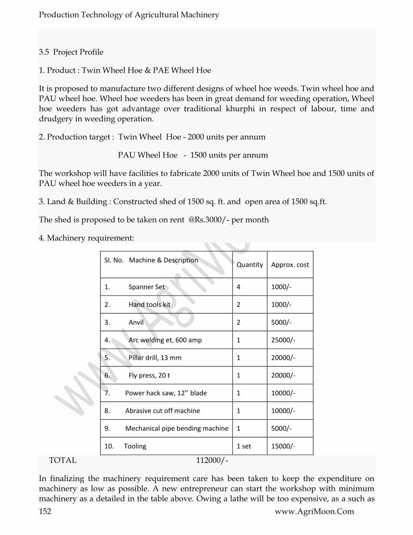
Production Technology of Agricultural Machinery
152 www.AgriMoon.Com
3.5 Project Profile
1. Product : Twin Wheel Hoe & PAE Wheel Hoe
It is proposed to manufacture two different designs of wheel hoe weeds. Twin wheel hoe and PAU wheel hoe. Wheel hoe weeders has been in great demand for weeding operation, Wheel hoe weeders has got advantage over traditional khurphi in respect of labour, time and drudgery in weeding operation.
2. Production target : Twin Wheel Hoe - 2000 units per annum
PAU Wheel Hoe - 1500 units per annum
The workshop will have facilities to fabricate 2000 units of Twin Wheel hoe and 1500 units of PAU wheel hoe weeders in a year.
3. Land & Building : Constructed shed of 1500 sq. ft. and open area of 1500 sq.ft.
The shed is proposed to be taken on rent @Rs.3000/- per month
4. Machinery requirement:
SI. No. Machine & Description
Quantity Approx. cost
1. Spanner Set 4 1000/-
2. Hand tools kit 2 1000/-
3. Anvil 2 5000/-
4. Arc welding et, 600 amp 1 25000/-
5. Pillar drill, 13 mm 1 20000/-
6. Fly press, 20 t 1 20000/-
7. Power hack saw, 12’’ blade 1 10000/-
8. Abrasive cut off machine 1 10000/-
9. Mechanical pipe bending machine 1 5000/-
10. Tooling 1 set 15000/-
TOTAL 112000/-
In finalizing the machinery requirement care has been taken to keep the expenditure on machinery as low as possible. A new entrepreneur can start the workshop with minimum machinery as a detailed in the table above. Owing a lathe will be too expensive, as a such as

Production Technology of Agricultural Machinery
153 www.AgriMoon.Com
abrasive cut of machine has been proposed which can be used for cutting various sections like angle, rod,flat,pipe etc.Similarly Owing a power press will also be not economical, considering the size of sections involved in farbrication.It will be underutilized always. A fly press will be enough to meet out the fabrication requirement. For the components involving press work and heat treatment etc. Like in case of fabrication of blade, it is proposed that the same can be got done outside on contract basis.
5. Raw Material requirement:
This has been calculated from the manufacturing drawings of both the weeders.
S.NO. MATERIAL Qty Unit Weight Qty by weight (kg) Rate (Rs./kg)
Approx. Cost
1. ISRO 12 200m 0.89 178 17 3000
2. ISRO 10 7500m 0.62 4650 17 79000
3. ISRO 6 3225m 0.22 710 17 120000
4. IST 40 32 m - - 90 per m 3000
5. IST 25 5400 m - - 20 per m 108000
6. IST 18 3450 m - - 16 per m 55200
7. IST 14 , 2 thick 45 m - - 30 per m 1400
8. ISSQ 16 38 m 2.01 765 17 13000
9. ISSQ 12 480 m 1.13 542 17 9200
10. ISF 65 X 5 102 m 2.5 255 17 4300
11. ISF 30 X 5 260 m 1.2 312 17 5300
12. ISF 30 X 3 420 m 0.7 294 17 5000
13. ISF 25 X 5 2530m 1.0 2530 17 43000
14. ISF 20 X10 1200 m 1.6 1920 17 32600
15. MS Sheet 3mm 36 sq.m 24.70 890 22 19600
16. Standard axle 3675 nos. - - 20 15000
17. Nut bolts 500 kg - - 30 15000
Total (say) 480000
Note The quantity includes 5 & 10 % allowance towards wastage on account of scrap/rejection for purchased & sheet metal parts.

Production Technology of Agricultural Machinery
154 www.AgriMoon.Com
6. Manpower:
S.No Description Man Days Rate (Rs/man-days)
Amount
1. Supervisor or Entrepreneur 300 100/- 30000/-
2. Skilled technician 600 100/- 60000/-
3. Unskilled worler 600 70/- 42000/-
Total 132000/-
7. Miscellaneous expenditure (20% of rows material): Rs.96000/- (Say)
This also includes expenditure on contract services like press work, shaping work, heat treatment etc.
8. Total working capital (Monthly basis)
i. Rent of building : Rs.3000/-
ii. Cost of raw material : Rs.40000/-
iii. Overhead expenditure : Rs. 8000/-
iv. Salary : Rs.11000/-
Total : Rs. 62000/-
9. Essential working capital (for 3 months) : Rs. 186000/-
10. Total project cost
i. Cost of machinery : Rs.112000/-
ii. Essential working capital : Rs.186000/-
Total : Rs.298000/-
11. Production Cost
i. Annual Working Capital : Rs.744000/-
ii. Depreciation : Rs. 11200/-
iii. Interest on capital from bank @ 14% : Rs. 31300/-
(75% of project cost)

Production Technology of Agricultural Machinery
155 www.AgriMoon.Com
Total : Rs.786500/-
12. Profit from unit :
i. Scale proceed:
Twin wheel hoe 2000 units @ Rs.250 /- each : Rs . 5,00,000 /
PAU wheel hoe 1500 units @ Rs. 300 / - each : Rs . 4,50,000
ii. Profit ( scale proceed –production cost ) : Rs.1,63,500/-
iii. Monthly profit (Say) : Rs .13,625/-
13. Break Even Point :
14. Pay back period :
15. Return on investment :

Production Technology of Agricultural Machinery
156 www.AgriMoon.Com
LESSON 21. CRITICAL COMPONENTS AND THEIR SELECTION
4.1 What is a component?
When a machine, for instance a power thresher, is exploded, it is resolved into a number of sub-assemblies, and then each sub-assembly into a number of parts. A is the last exploded unit which may perform independent function in a machine. A part or a group of parts together in a machine is addressed as a component. As for instance, the gear box in a reaper comprises of number of parts and hence it may be called a component . However, there exists a dichotomy between a part and a component and these two terms are often interchangeably used or used at times together as component part. Thus a part is a subset of a component. In a part, the various portions labelled with dimensions are called links.
4.1.1 Meaning of critical
The term ―critical‖ is related to decision-making or crisis or turning point.
4.1.2 What is a critical component?
The component responsible for creating a crisis by its wrong-working or faltering is called critical. A component may be critical in a machine, and so also a part. Thus, a critical component or say a critical part in a machine will cause the machine to dysfunction if the same is not properly designed, manufactured or repaired/maintained or selected. But most critical components or parts are available in market in ready-to-use form, the selection of which is, therefore, very important for the particular machine and conditions of operation. As for instance, the examples of these are bearings & housings, pulleys & belt, gears etc. Besides, the same critical components or parts may be fabricated also. These are, for example, lynch pins of tractor mounted implements. Thus, most of the critical parts and components are available in the market as standard material and no separate effort is, there-fore, required to design and fabricate them. One is, therefore, required to select the right one. A glimpse of such parts is presented in next section.
4.2. Standard Parts
4.2.1 Common bought-out parts
Almost all types of standard parts used commonly in common machines are also used in agricultural equipment. A classification of the standard bought-out parts is presented in Fig.1. The criteria of selection of individual part are dealt in the subsequent sections through a few example cases.
4.2.2 Specific bought-out parts
Some parts used in agricultural equipment are not normally used in other machines but are specific to one more agricultural equipment. These have been in exhaustively listed in Table

Production Technology of Agricultural Machinery
157 www.AgriMoon.Com
1. Some industries fabricate of them in their own units along with other components of implements and therefore they may not conform to standard dimensions.
Figure : 1
Table 1 . Bought-out / fabricated parts specific to agrl. Equipment
(This list is illustrative only.)

Production Technology of Agricultural Machinery
158 www.AgriMoon.Com
4.3.Selection criteria
In this lecture note, only a few parts have been selectively covered to explain criteria of selection. One may need to look into the following general criteria in selecting a critical component part.
i. Material
ii. Intricacy of design
iii. Quality of manufacturing
iv. Metallurgy, longevity, wearing, etc.
v. Space limitations
vi. Load and power
vii. Cost
4.4. Material:
Material finds an important place in design of a critical component part of agriculture equipment. The performance and reliability of a component depends largely on the type and quality of material used in the parts and process of manufacturing. The quality of material refers to the following and is desirable for the design engineer to tread a course between functional quality requirement on one hand and cost consideration on the other although quality may over ride cost in some rare cases.
i. Strength
ii. Toughness
iii. resistance to wear and corrosion
iv. good scour (quality of material to allow easy flow)
v. lightness of weight, and
vi. low initial cost and subsequent upkeep requirement
In the present days, design is no longer and the consideration of time factor these days has necessitated the knowledge of the right materials and their use right from the beginning. It is also important to update one‘s knowledge of new material being introduced every day in order to maximize on their use.
4.5. Specific cases
Here we deal with a few case examples to introduce the ideal of selection of critical components.

Production Technology of Agricultural Machinery
159 www.AgriMoon.Com
4.5.1 Bearing
For a bearing it is important to know in the first instant the nature of loads the bearing is to carry. According to the type of loading namely axial, radial or mixed, the bearings have been classified as shown in Fig 2.
Selection of bearing
Bearing are classified in the manner as shown in Fig 2. The types of bearing and their nature of loading like radial, axial and mixed besides speed of operation have been give in this section. Moreover, it is also important to know the relationship between the load and life of bearing. The relationship is established by Eqs.1 & 2 and life calculation chart. Similarly the class of machines and their useful lives are presented in Table 2 for deciding the types of bearing to be used.
Fig.1. classification of bearings according to load
Revised life equations established by ISO 281 are:
Where,
La = Adjusting rating life, h
Lb = Basic operating life, h
a1 = life adjustment factor for reliability

Production Technology of Agricultural Machinery
160 www.AgriMoon.Com
a23 = Combined life adjustment factor for material and operating condition
n = rpm
C = Basic Dynamic Load Rating, Newton
P = Equivalent Dynamic Bearing Load, Newton
q= exponent for life equation = 3 for ball bearing and 10/3 for roller bearing, and
C/P = Load ratio
Rise in operating temperature affects the hardness and bearing material. This affects C by the factor of temperature, f, as C.f.
Bearing temperature,0C
Bearing temperature,0C 150 200 250 300
Temperature factor, f 1.0 0.9 0.75 0.6

Production Technology of Agricultural Machinery
161 www.AgriMoon.Com
Table2.Class of machines and their basic operating lives
S.NO Class of machine Basic operating life, h
1 Domestic & Agril.Machine 300-3,000
2 Electric hand tools & other intermitted machines 3,000-8,000
3 High operational reliability for short periods 8,000-12,000
4 Machine used 8h/d but not fully utilized 10,000-25,000
5 Machines used 8h/d and fully utilized 20,000-30,000
6 Machines used 24h/d like pumps, compressors etc. 40,000-50,000
7 Rotary furnace , water works 60,000-1,00,000
8 Large electric machinery, pulp& paper making machinery >1,00,000
Similarly the values of a, are also given by Table 3.
Reliability means the probability that a bearing will or exceed a specified life
Table 3. Reliability * versus a1
S NO. Reliability,% A S NO. Reliability,% a S NO. Reliability,% a
1 90 1 3 96 0.53 5 98 0.33
2 95 0.62 4 97 0.44 6 99 0.21
a: The value of a is obtained in the following manner.
*Reliability means the probability that a bearing will attain or exceed a specified life.
For a selected roller bearing cylindrical bore of 18?5=90mm,22318CC/W33, W33 Feature is peripheral groove and 3 lubrication holes in the outer ring, value are:d =inside bore = 90 mm;
іD₀=outside diameter=190mm;
Thus d =average diameter =(90+190)/2=140mm.From Fig 4 corresponding to
dm=140mm,v =Satisfactory oil viscosity =21 mm²аа/s at 500 rpm.
Hence ,k=v/v=35₍as given₎/21=1.61 and from Fig 5,fork=1.67,a₂₃=1.4

Production Technology of Agricultural Machinery
162 www.AgriMoon.Com
Thus,Lа=a₁.a₂₃‗10⁶/60n(C/P)q=0.33(1.4)‘10⁶/60‘500(4,77,000/50,000)10/3=28358h
Lengend:—Normal lubricants
--..Lubricants WithEp additives , etc.
4.5.2 Gear selection
In agricultural equipment, two types of gears are most common. These are spur and bevel gears. In these sections, selections of spur gear are presented.
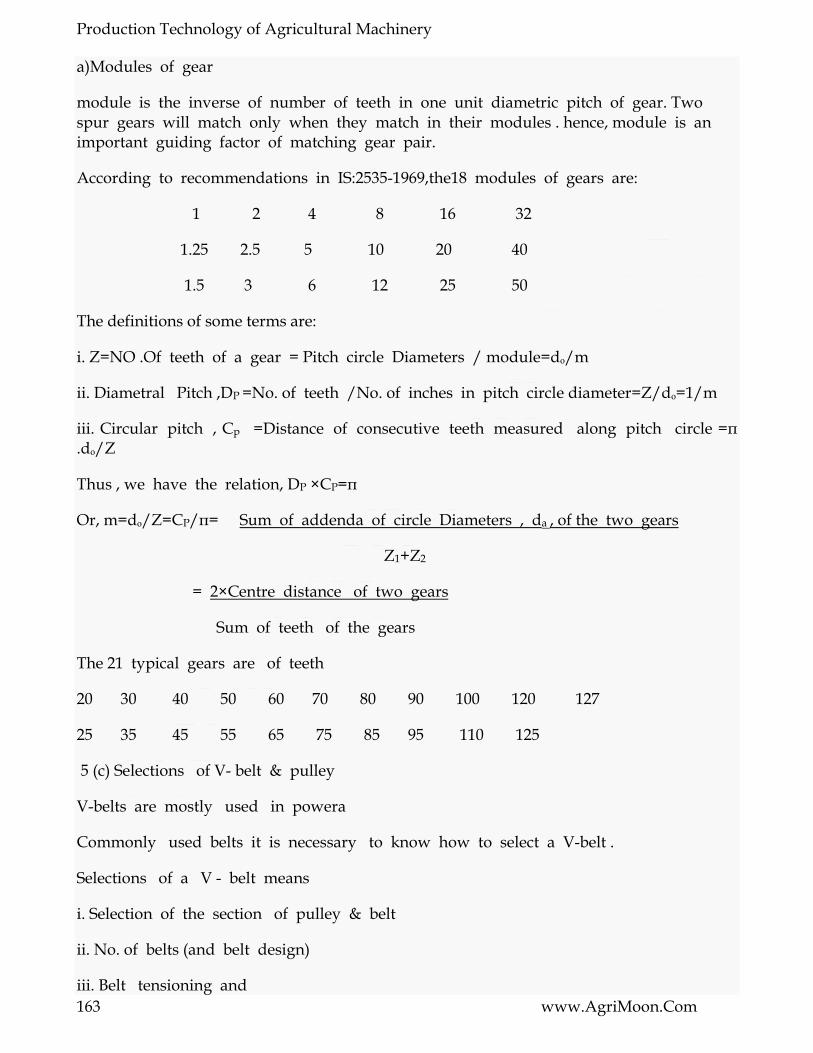
Production Technology of Agricultural Machinery
163 www.AgriMoon.Com
a)Modules of gear
module is the inverse of number of teeth in one unit diametric pitch of gear. Two spur gears will match only when they match in their modules . hence, module is an important guiding factor of matching gear pair.
According to recommendations in IS:2535-1969,the18 modules of gears are:
1 2 4 8 16 32
1.25 2.5 5 10 20 40
1.5 3 6 12 25 50
The definitions of some terms are:
i. Z=NO .Of teeth of a gear = Pitch circle Diameters / module=dₒ/m
ii. Diametral Pitch ,DP =No. of teeth /No. of inches in pitch circle diameter=Z/dₒ=1/m
iii. Circular pitch , Cp =Distance of consecutive teeth measured along pitch circle =π .dₒ/Z
Thus , we have the relation, DP ×CP=π
Or, m=dₒ/Z=CP/π= Sum of addenda of circle Diameters , da , of the two gears
Z1+Z2
= 2×Centre distance of two gears
Sum of teeth of the gears
The 21 typical gears are of teeth
20 30 40 50 60 70 80 90 100 120 127
25 35 45 55 65 75 85 95 110 125
5 (c) Selections of V- belt & pulley
V-belts are mostly used in powera
Commonly used belts it is necessary to know how to select a V-belt .
Selections of a V - belt means
i. Selection of the section of pulley & belt
ii. No. of belts (and belt design)
iii. Belt tensioning and

Production Technology of Agricultural Machinery
164 www.AgriMoon.Com
iv. Care and conditions of use
However ,V-belts should satisfy quality - standards in BS-3790 or DIN-2215 or IS-2494 (for V-belt in power rating ) & IS : 3142 (for cast iron pulley sections).
1. Selection of section of pulley and belt
V-belts and pulley come in standard sections of A,B,C,D and E. And some special sections among five are also manufactured in belts by some manufacturers. The sectional geometries of the belts and pulleys and are presented in Fig 6 while the dimensions in Table 4
section Belt attributes Pulley attributes
W mm
Ip mm
H mm
Belt speed m/s
Belt wt.kg/m
B mm
t mm
e mm
f mm
? mm
dp mm
g mm
W for belt width; ᴵp for belt pitch width; H for belt height; b for addendum; t for groove height; e for pitch of groove end distance; ? for groove angle; dp for pulley diameter min; g for groove top width
A 13 11 8 30 0.112 3.3 12 15±0.3 9 to 0.4
34
75 to 124
13
38 ³125 13.3
B 17 14 11 30 0.193 4.2 15 19±0.4 11.5to 14.5
34
125 to199
16.6
38 ³200 16.9

Production Technology of Agricultural Machinery
165 www.AgriMoon.Com
C 22 19 14 30 0.33 5.7 20 25±0.5 16 to 19
26
200to 299
22.7
28 ³300 22.9
D 32 27 19 30 0.675 8.1 28 37±0.6 23 to 27
36
355to 499
32.3
38 ³500 32.6
E 38 32 23 30 1.030 9.6 33 44.5±0.7 28 to 33
36
500to 629
38.2
38 ³630 38.6
The selection of pulley &belt both in any one category of A,B,C,D,E& any special category will depend on the factors like
Power to be transmitted
Speed at which to be transmitted, and
The working conditions.
Of course, the former two are more important because power=torque, T‘ angular motion ?.the angular rotation can be in terms of rpm(rotation of pulley per minute). For selection of the belt cross.
Fig 7 may be referred. From this figure, for a 5 kW of power transmission, we can select C-section V-belt to 175 rpm(on the ordinate)or B-section belt for rpm between 175 to 775 rpm(A&B on the ordinate) or A-section belt for rpm between 77 to 5,000rpm(p & q on the ordinate). And the further calculation of number of belts will decide whether the pulley will be of single groove.

Production Technology of Agricultural Machinery
166 www.AgriMoon.Com
Once section is graphically selected from fig. 7, the power which one belt of the selected section can transmit can be also selected from the power versus rpm given in Table 5 for given (standard) pulley diameters (pitch circle). Normally, the prime-movers are electrical motors; hence, the rpm are 720, 960, 1440 or 2880.
Table 5 Power transmission of belt
Pulley size in mm
Pulley section Capacity to transmit power ,Kw, at Pulley rpm
720 960 1440 2880
75 A 0.62 0.76 0.98 1.36
80 A 0.75 0.92 1.21 1.75
90 A 0.94 1.17 1.57 2.38
100 A 1.11 1.39 1.88 2.94
112 A 1.32 1.67 2.28 3057
125 A 1.54 1.95 2.68 4.26
125 B 2.00 2.46 3.23 4.39
132 B 2.25 2.79 3.70 5.08
140 B 2.41 3.01 4.00 5.58
160 B 3.03 3.79 5.08 7.10
180 B 3.57 4.51 6.04 8.31

Production Technology of Agricultural Machinery
167 www.AgriMoon.Com
200 B 4.21 5.29 7.12 -
200 C 5.50 6.78 8.75 -
212 C 6.16 7.61 9.86 -
224 C 6.63 8.21 10.65 -
250 C 8.00 9.92 12.84 -
280 C 9.28 11.49 14.79 -
355 C 12.89 15.82 19.7 -
355 D 20.52 24.51 24.58 -
375 D 22.52 26.88 - -
400 D 25.00 29.70 - -
450 D 29.76 35.09 - -
500 D 34.25 39.89 - -
560 D 39.33 44.84 - -
450 E 27.20 30.68 - -
500 E 32.13 35.34 - -
600 E 41.60 - - -
630 E 44.25 - - -
710 E 50.40 - - -
750 E 52.97 - - -
Number of belts
The procedure to calculate the number of belts once the belt & pulley section is determined previously from fig 7 can be explained in the following steps with the of an example of driving a centrifugal at 2400 rrpm being run 18 hours a day by a 22 kW, 2880 rpm, 3-phase electrical (A.C) motor at 600mm centre distance. The steps involved to calculate the number of belts are:

Production Technology of Agricultural Machinery
168 www.AgriMoon.Com
SI NO
Step Calculation
1 Determine the belt & pulley section from fig 7 corresponding to p=22kW of power and n=2880 rpm
B section of belt & pulley for n=2880 rpm & p=22kW
2 Calculate speed ratio, r,from r=N1/N2=Dp/dp R=2880/2400=1.2
3
Select the motor pulley from amongst the standard preperred diameters (PCD) of 85,90,100,106,112,118,140,150,160,170,180,190,200, 224,212,236,250,265,280,315,355,375,400,425,450,500, 530,560,600mm and some non-preferred ones of 75,80,125,132,670,710,750,800,850,900,950 &1000.
We select Dp=smaller pulley for motor =150 mm
4 Compute C2=service factor from Table 6 C2=1.2 from table 6 against light-duty,star-delta start & over 16 hours of works/day
5 Pitch diameter of slower pulley,Dp=r xdp Dp=1.2 x 150 =180 mm
6 Check drive center distance C, suitable if 0.7 (Dp+dp)<2.0 (Dp+dp)
C=600mm as chosen is OK.
7 Select belt length (pitch) from Lp=2C+1.57(Dp+dp)+(Dp-dp)2 / 4C
Lp=2x600+1.57(180+150)=180-150)2 / 4x600)=1718mm; and from Table 7,the nearest standard length isn1720 mm=L
8
Cc,Ca C=C+(L-Lp)/2 if l>lp Or C=C-(L-Lp) /2 if L<Lp K=(L- /2 (Dp+dp)) /4 Ca=K+(K2-(Dp-dp)2 /8))
Cc=600 +(1720-1718)/2=601 mm and Ca= 600.76mm
9 For arc of contact correction factor, C1,take the value of C1 from Table 8 corresponding to (Dp-dp)/c
(180-150)/600=0.05 C1 =0.99 Corresponding to .05 from Table 8
10 For correction factor, C3,of belt length, choose C3 from Table 9 corresponding to L
C3 =0.94 from Corresponding to L=1720mm
11 Power rating pern belt, Pn Pn is taken from Table 10 corresponding to r, n & dp
Pn = 5.55+0.50=6.05 kW for r=1.2; n=2880 rpm and dp=150mm from Table 10
12 No. Of belts,Z Z=(pxC2)/(pnxC2xC3)
Z=(22x1.2)/6.05x0.99x0.94)=4.69 -5(taking next whole number)
Thus 5 units of B 66/1760 belts will be required to transmit 22kW power.

Production Technology of Agricultural Machinery
169 www.AgriMoon.Com
3. Belt tensioning
Proper belt tensioning would not allow slip of belt on the pulley under maximum load condition. The procedure to ensure proper belt tensioning is as follows:
Step1. Apply the recommended load for the belt section and calculate deflation of belt, Ea, under the recommended load by the relation Ea=(ExC)/100
Where, E=Deflation/ 100mm of centre-to-centre distance.Take this value from
Table11
C=Centre-to-centre distance,mm;
The load is applied at the centre of belt span perpendicularly.
Step2. Adjust the drive until until the calculated deflation ‗Ea‘ is obtained.
Step 3. In case of belt under long-time use,Ea increases to 1.3Ea for which retensioning is required.
Table 6 Service factor, C2, for belt drives
Class of duty
Type of driven machine C2
Type of prime mover
SOFT START HEAVY START
PER DAY DUTY HOURS
PER DAY DUTY HOURS
<10 10 TO 20
<16 <10 10 TO 16
>16
Light duty
Agitators (uniform),blowers,exhausters & fans (<7.5 kW),centrifugal compressors, pumps,belt conveyors (uniform)
1.1 1.1 1.2 1.1 1.2 1.3
Medium of duty
Agitators,mixers (Variable), blowers,exhausters,fans (>7.5 kW),(Noncentrifugal),rotary compressors, pumps,belt conveyors (non uniform),generator,exciter,power shaft,machines tools,wood working machines, screws (rotary)
1.1 1.2 1.3 1.2 1.3 1.4
Heavy of duty
Bucket elevator, compressors, pumps (reciprocating), conveyor (heavy duty),hoists,mills,pulverisers, punching machine,press, shear,screw (vibrating)
1.2 1.3 1.4 1.4 1.5 1.6

Production Technology of Agricultural Machinery
170 www.AgriMoon.Com
Extra heavy duty
Crushers (gyrator – jaw roll), mills (ball-rod-tube) 1.3 1.4 1.5 1.5 1.6 1.8
Note: 1. Correct the tabulated C2 value by the factors.
Speed ratio of 1.00 To 1.24 multiply C2 by
-do- 1.25 to 1.74 multiply C2 by
-do- 1.75 to 2.49 multiply C2 by
-do- 2.50 to 3.49 multiply C2 by
-do- 3.50 and multiply C2 by
2.Soft start prime movers are AC are star-delta,shunt wound DC motor, IC engines with >-4 cyclinder, etc.
3. Heavy start prime movers are AC Direct-on-line start, DC series & compound wound, IC engines <4 cyclinders.
Table 7 V-belt sizes of polyester cord
S.No
Section
1 A
A23/620,A24/645,…….,A76/1966(by Step of 1‖/25mm),A78/2017,A80/2068,……,A84/2195(by step of 2‖/50mm),A85/2195,A86/2220,……,A98/2525(by step of 1‖/25mm);A100/2516,A102/2626,…..,A112/2880(by step of2‖/50mm);A114/2932,A115/2982,A118/3033,A120/3064,A124/3186,A125/3211,A126/3236,A128/3267,A130/3338,A134/3440,A136/3490,A138/3541,A140/3696,A144/3793,A154/4430and A174/4456
2 B Length(inch / mm
3 C
C46/1224,C48/1275,C49/1301,C51/1351,C5/1453,C60/1580,C63/1656,C68/1783,C71/1859,C75/1961,C77/2012,C78/2037,C81/2113,C85/2215,C86/2280,C87/2266,C88/2291,C89/2317,C90/2342,C91/2367,C92/2393,C93/2418,C94/2444,C95/2469,C96/2494,C97/2590,C98/2545,C99/2571,C100/2596,C101/2621,…..C130/3358 by step of
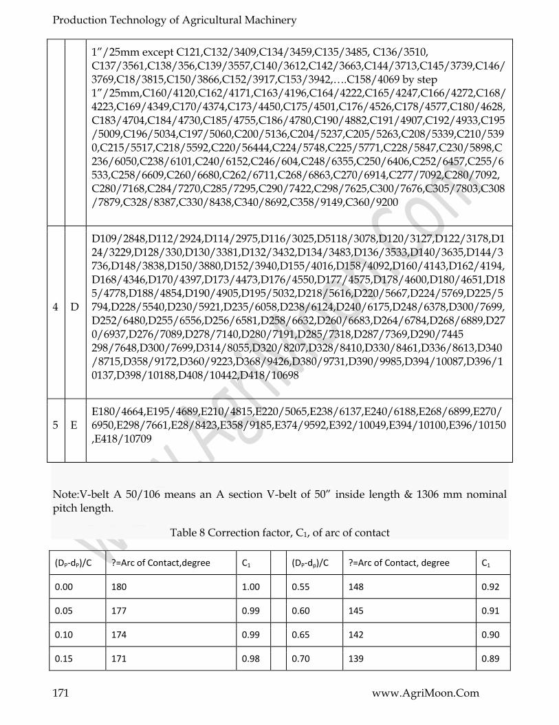
Production Technology of Agricultural Machinery
171 www.AgriMoon.Com
1‖/25mm except C121,C132/3409,C134/3459,C135/3485, C136/3510, C137/3561,C138/356,C139/3557,C140/3612,C142/3663,C144/3713,C145/3739,C146/3769,C18/3815,C150/3866,C152/3917,C153/3942,….C158/4069 by step 1‖/25mm,C160/4120,C162/4171,C163/4196,C164/4222,C165/4247,C166/4272,C168/4223,C169/4349,C170/4374,C173/4450,C175/4501,C176/4526,C178/4577,C180/4628,C183/4704,C184/4730,C185/4755,C186/4780,C190/4882,C191/4907,C192/4933,C195/5009,C196/5034,C197/5060,C200/5136,C204/5237,C205/5263,C208/5339,C210/5390,C215/5517,C218/5592,C220/56444,C224/5748,C225/5771,C228/5847,C230/5898,C236/6050,C238/6101,C240/6152,C246/604,C248/6355,C250/6406,C252/6457,C255/6533,C258/6609,C260/6680,C262/6711,C268/6863,C270/6914,C277/7092,C280/7092,C280/7168,C284/7270,C285/7295,C290/7422,C298/7625,C300/7676,C305/7803,C308/7879,C328/8387,C330/8438,C340/8692,C358/9149,C360/9200
4 D
D109/2848,D112/2924,D114/2975,D116/3025,D5118/3078,D120/3127,D122/3178,D124/3229,D128/330,D130/3381,D132/3432,D134/3483,D136/3533,D140/3635,D144/3736,D148/3838,D150/3880,D152/3940,D155/4016,D158/4092,D160/4143,D162/4194,D168/4346,D170/4397,D173/4473,D176/4550,D177/4575,D178/4600,D180/4651,D185/4778,D188/4854,D190/4905,D195/5032,D218/5616,D220/5667,D224/5769,D225/5794,D228/5540,D230/5921,D235/6058,D238/6124,D240/6175,D248/6378,D300/7699,D252/6480,D255/6556,D256/6581,D258/6632,D260/6683,D264/6784,D268/6889,D270/6937,D276/7089,D278/7140,D280/7191,D285/7318,D287/7369,D290/7445 298/7648,D300/7699,D314/8055,D320/8207,D328/8410,D330/8461,D336/8613,D340/8715,D358/9172,D360/9223,D368/9426,D380/9731,D390/9985,D394/10087,D396/10137,D398/10188,D408/10442,D418/10698
5 E E180/4664,E195/4689,E210/4815,E220/5065,E238/6137,E240/6188,E268/6899,E270/6950,E298/7661,E28/8423,E358/9185,E374/9592,E392/10049,E394/10100,E396/10150,E418/10709
Note:V-belt A 50/106 means an A section V-belt of 50‖ inside length & 1306 mm nominal pitch length.
Table 8 Correction factor, C1, of arc of contact
(DP-dP)/C ?=Arc of Contact,degree C1 (DP-dp)/C ?=Arc of Contact, degree C1
0.00 180 1.00 0.55 148 0.92
0.05 177 0.99 0.60 145 0.91
0.10 174 0.99 0.65 142 0.90
0.15 171 0.98 0.70 139 0.89

Production Technology of Agricultural Machinery
172 www.AgriMoon.Com
0.20 169 0.97 0.75 136 0.88
0.25 166 0.97
0.30 163 0.96 0.80 133 0.87
0.35 160 0.95 0.85 130 0.86
0.40 157 0.94 0.90 127 0.85
0.45 154 0.93 0.95 123 0.83
0.50 151 0.93 1.00 120 0.82
Table 9 Length Correction Factor, C3
C3 Length for belt section, mm C3 Length for belt section, mm
A B C D E
A B C D E
0.80 630 1.02 1940 2500 4060
0.81 930 1.03 6890
0.82 700 1560 2740 1.04 2050 2700
0.83 1000 1.05 2200 2850 4600 7620
0.84 790 1760 1.06 2300
0.85 1100 1.07 8410
0.86 890 3130 1.08 2480 3200 5380
0.87 1210 1950 3330 1.09 2570 9140
0.88 990 1.10 2700 3600 6100
0.89 1.11
0.90 1100 1370 2190 3730 1.12 2910 6860 10700
0.91 2340 1.13 3080 4060
0.92 1560 2490 4080 1.14 3290 7600
0.93 1250 1.15 4430
0.94 2720 4620 1.16 3540 4820 12200
0.95 1760 2800 1.17

Production Technology of Agricultural Machinery
173 www.AgriMoon.Com
0.96 1430 3080 1.18 5000 13700
0.97 1950 3310 5400 1.19 5370
0.98 1550 3520 1.20 6070 15200
0.99 1640 2180 1.21 9100
1.00 1750 2300 6100 1.24 10700
Table 10 Power rating of belt,Pn, for smaller pulley(or faster pulley) (θ =1800)
Section A belt
Speed of Faster Pulley,(rpm)
Power in KW for pitch diameter, dp, Of smaller pulley, mm
Add power in kw for r of
75
80 85 90 100 106 112 118 125
1.01 to 1.04
1.05 to 1.12
1.1 3to 1.24
1.25 to 1.51
1.52 & above
720 0.53
0.60
0.68
0.75
0.90
0.99
1.07
0.16
1.26
0.01
0.03
0.05
0.07
0.09
960 0.66
0.76
0.86
0.95
1.14
1.25
1.37
1.49
1.61
0.01
0.04
0.06
0.09
0.12
1440 0.91
1.04
1.17
1.31
1.58
1.73
1.90
2.07
2.24
0.02
0.06
0.10
1.14
0.17
2880 1.42
1.67
1.91
2.14
2.59
2.76
3.11
3.36
3.63
0.04
0.12
0.20
0.27
0.35
Section B belt
rpm dp= 125
132 140 150 160 170 180 190 200 Speed ratio r is same
720 1.61 1.79 1.99 2.24 2.48 2.73 2.97 3.21 3.45 0.03 0.08 0.13 0.18 0.23
960 2.02 2.24 2.50 2.82 3.13 3.44 3.75 4.05 4.35 0.03 0.10 0.17 0.24 0.30
1440 2.72 3.03 3.39 3.8 4.26 4.68 5.09 5.50 5.90 0.05 0.15 0.25 0.36 0.46
2880 3.96 4.44 4.95 5.55 6.11 6.62 7.08 7.48 - 0.10 0.30 0.50 0.71 0.91

Production Technology of Agricultural Machinery
174 www.AgriMoon.Com
Section C belt
rpm dp= 300
212 224 236 250 265 280 31 5
355 400 Speed ratio r is same
720 4.65 5.18 5.70 6.22 6.81 7.44
8.06
9.49
1105
1275
0.07
0.21
0.35
0.49
0.63
Section D belt
rpm dp = 355
375 400 425 450 475 500 530 560 600 Speed ratio r is same.
720 16.26
17.90
19.90
21.85
23.75
23.59
27.38
29.44
31.42
33.91
0.25
0.75
1.25
1.75
2.22
960 19.26
21.16
23.45
25.63
27.70
29.65
31.47
33.50
35.32
- 0.33
1.00
1.67
2.33
3.00
1440
21.22
23.03
- - - - - - - - 0.50
1.50
2.50
3.50
4.50
Section E belt
960
5.76
6.42
7.08
7.72
8.46
9.24
10.00
11.72
13.58
15.51
0.09
0.28
0.47
0.66
0.85
1440
7.49
8.36
9.21
10.03
10.95
11.91
12.82
14.76
16.67
-
0.14
0.42
0.71
0.99
1.27
2800
8.05
0.27
0.82
1.37
1.92
2.47
rpm
dp= 450
500 560 630 670
710 750 800 850
900
950
100
r= 1.01 to 1.04
r= 1.05 to 1.12
r= 1.27 to 1.57
>157
72 26.4 31.6 37.5 43.7 47. 49.9 52.6 55.6 0.3 1.9 3.0 3.4

Production Technology of Agricultural Machinery
175 www.AgriMoon.Com
0 4 9 6 8 0 7 7 6 8 2 7 5
960
29.77
35.29
40.94
46.07
- - - 0.52
2.60
4.16
4.68
Table 11 Deflection, of belt per 100mm of C
Belt section
Applied Load on belt (Newton)
dp=Small pulley diameter (mm)
Deflection, E, per 100mm of C (mm)
Belt section
Applied Load on belt (Newton)
dp=Small pulley diameter (mm)
Deflection, E, per 100mm of C(mm)
A
25
75≤dp ≤100 100<dp≤1 32 dp>132
1.90 1.70 1.50
C
100
200≤dp ≤265 265<dp ≤355 dp>355
2.30 2.10 2.00
B
50
125≤dp 160≤ 160<dp ≤200 dp>200
2.30 2.10 1.90
D
150
355≤dp ≤450 450<dp ≤670 dp>670
2.20 2.10 2.10
4. Conditions of use
1. Belts of a matched set of required number of correct length and section of the same make and not in a mix-up of new and old should be used.
2. Pulleys of uniform and smooth (Ra<6.3µ) free of oil & grease and monted close to the bearings should be used.
3. Pulleys higher than 30m/s of speed be dynamically balanced.
4. Belts should be stored at 13 to 25C in dry & light-free place & used in temperature medium not exceeding 60C.
5. Idler pulley to provide requisite tension should be flat placed externally on slack side and should be grooved, placed internally on the slack side of diameter at least equal to the smaller pulley such that a=contact angle same for both the puleys.
Production Technology of Agricultural Machinery
176 www.AgriMoon.Com
MODULE 8. Servo motors, drives and controllers
LESSON 22. INTRODUCTION OF SERVO MOTORS
1.1 Introduction
A servomotor is a rotary actuator that allows for precise control of angular position, velocity and acceleration. It consists of a motor coupled to a sensor for position feedback. It also requires a relatively sophisticated controller, often a dedicated module designed specifically for use with servomotors. Servomotors are used in applications such as robotics, CNC machinery or automated manufacturing.
Mechanism
As the name suggests, a servomotor is a servomechanism. More specifically, it is a closed-loop servomechanism that uses position feedback to control its motion and final position. The input to its control is some signal, either analogue or digital, representing the Position commanded for the output shaft.
The motor is paired with some type of encoder to provide position and speed feedback. In the simplest case, only the position is measured. The measured position of the output is compared to the command position, the external input to the controller. If the output position differs from that required, an error signal is generated which then causes the motor to rotate in either direction, as needed to bring the output shaft to the appropriate position. As the positions approach, the error signal reduces to zero and the motor stops.

Production Technology of Agricultural Machinery
177 www.AgriMoon.Com
The very simplest servomotors use position-only sensing via a potentiometer and bang-bang control of their motor; the motor always rotates at full speed (or is stopped). This type of servomotor is not widely used in industrial motion control, but they form the basis of the simple and cheap servos used for radio-controlled models. More sophisticated servomotors measure both the position and also the speed of the output shaft. They may also control the speed of their motor, rather than always running at full speed. Both of these enhancements, usually in combination with a PID control algorithm, allow the servomotor to be brought to its commanded position more quickly and more precisely, with less overshooting.
Servomotors vs. stepper motors
Servomotors are generally used as a high performance alternative to the stepper motor. Stepper motors have some inherent ability to control position, as they have built-in output steps. This often allows them to be used as an open-loop position control, without any feedback encoder, as their drive signal specifies the number of steps of movement to rotate. This lack of feedback though limits their performance, as the stepper motor can only drive a load that is well within its capacity, otherwise missed steps under load may lead to positioning errors. The encoder and controller of a servomotor are an additional cost, but they optimise the performance of the overall system (for all of speed, power and accuracy) relative to the capacity of the basic motor. With larger systems, where a powerful motor represents an increasing proportion of the system cost, servomotors have the advantage. Many applications, such as laser cutting machines, may be offered in two ranges, the low-priced range using stepper motors and the high-performance range using servomotors.
Encoders
Simple servomotors may use resistive potentiometers as their position encoder. These are only used at the very simplest and cheapest level, and are in close competition with stepper

Production Technology of Agricultural Machinery
178 www.AgriMoon.Com
motors. They suffer from wear and electrical noise in the potentiometer track. Although it would be possible to electrically differentiate their position signal to obtain a speed signal, PID controllers that can make use of such a speed signal generally warrant a more precise encoder.
Modern servomotors use optical encoders, either absolute or incremental. Absolute encoders can determine their position at power-on, but are more complicated and expensive. Incremental encoders are simpler, cheaper and work at faster speeds. Incremental systems, like stepper motors, often combine their inherent ability to measure intervals of rotation with a simple zero-position sensor to set their position at start-up.
Many servomotors are rotary, but are used for ultimate control of a linear motion. In some of these cases, a linear encoder is used. These servomotors avoid inaccuracies in the drive train between the motor and linear carriage, but their design is made more complicated as they are no longer a pre-packaged factory-made system
Motors
The type of motor is not critical to a servomotor and different types may be used. At the simplest, brushed permanent magnet DC motors are used, owing to their simplicity and low cost. Small industrial servomotors are typically electronically-commutated brushless motors. For large industrial servomotors, AC induction motors are typically used, often with variable frequency drives to allow control of their speed. For ultimate performance in a compact package, brushless AC motors with permanent magnet fields are used, effectively large versions of Brushless DC electric motors.
Drive modules for servomotors are a standard industrial component. Their design is a branch of power electronics, usually based on a three-phase MOSFET H bridge. These standard modules accept a single direction and pulse count (rotation distance) as input. They may also include over-temperature monitoring, over-torque and stall detection features. As the encoder type, gear head ratio and overall system dynamics are application specific, it is more difficult to produce the overall controller as an off-the-shelf module and so these are often implemented as part of the main controller.
Controllers
Most modern servomotors are designed and supplied around a dedicated controller module from the same manufacturer. Controllers may also be developed around microcontrollers, but this is rarely worth the time and trouble, compared to buying off-the-shelf.
What is the difference between a DC motor and servo motor?

Production Technology of Agricultural Machinery
179 www.AgriMoon.Com
A DC motor has a two wire connection. All drive power is supplied over these two wires. think of a light bulb. When you turn on a DC motor, it just starts spinning round and round. Most DC motors are pretty fast, about 5000 RPM (revolutions per minute).
With the DC motor, its speed (or more accurately, its power level) is controlled using a technique named pulse width modulation, or simply PWM. This is idea of controlling the motor‘s power level by strobing the power on and off. The key concept here is duty cycle—the percentage of ―on time‖ versus―off time.‖ If the power is on only 1/2 of the time, the motor runs with 1/2 the power of its full-on operation.
If you switch the power on and off fast enough, then it just seems like the motor is running weaker—there‘s no stuttering. This is what PWM means when referring to DC motors. The Handy Board‘s DC motor power drive circuits simply switch on and off, and the motor runs more slowly because it‘s only receiving power for 25%, 50%, or some other fractional percentage of the time.
A servo motor is an entirely different story. The servo motor is actually an assembly of four things: a normal DC motor, a gear reduction unit, a position-sensing device (usually a potentiometer—a volume control knob), and a control circuit.
The function of the servo is to receive a control signal that represents a desired output position of the servo shaft, and apply power to its DC motor until its shaft turns to that position. It uses the position-sensing device to determine the rotational position of the shaft, so it knows which way the motor must turn to move the shaft to the commanded position. The shaft typically does not rotate freely round and round like a DC motor, but rather can only turn 200 degrees or so back and forth.
The servo has a 3 wire connection: power, ground, and control. The power source must be constantly applied; the servo has its own drive electronics that draw current from the power lead to drive the motor.
The control signal is pulse width modulated (PWM), but here the duration of the positive-going pulse determines the position of the servo shaft. For instance, a 1.520 millisecond pulse is the center position for a Futaba S148 servo. A longer pulse makes the servo turn to a clockwise-from-center position, and a shorter pulse makes the servo turn to a counter-clockwise-from-center position.
The servo control pulse is repeated every 20 milliseconds. In essence, every 20 milliseconds you are telling the servo, ―go here.‖

Production Technology of Agricultural Machinery
180 www.AgriMoon.Com
To recap, there are two important differences between the control pulses of the servo motor versus the DC motor. First, on the servo motor, duty cycle (on-time vs. off-time) has no meaning whatsoever—all that matters is the absolute duration of the positive-going pulse, which corresponds to a commanded output position of the servo shaft. Second, the servo has its own power electronics, so very little power flows over the control signal. All power is draw from its power lead, which must be simply hooked up to a high-current source of 5 volts.
Contrast this to the DC motor. On the Handy Board, there are specific motor driver circuits for four DC motors. Remember, a DC motor is like a light bulb; it has no electronics of its own and it requires a large amount of drive current to be supplied to it. This is the function of the L293D chips on the Handy Board, to act as large current switches for operating DC motors.
Plans and software drivers are given to operate two servo motors from the HB. This is done simply by taking spare digital outputs, which are used to generate the precise timing waveform that the servo uses as a control input. Very little current flows over these servo control signals, because the servo has its own internal drive electronics for running its built-in motors.

Production Technology of Agricultural Machinery
181 www.AgriMoon.Com
LESSON 23. SERVO MOTORS
2.1 Introduction
A servo motor is a dc, ac, or brushless dc motor combined with a position sensing device (e.g. a digital decoder). In this section, our discussion will be focused on the three-wire DC servo motors that are often used for controlling surfaces on model airplanes. A three-wire DC servo motor incorporates a DC motor, a gear train, limit stops beyond which the shaft cannot turn, a potentiometer for position feedback, and an integrated circuit for position control Of the three wires protruding from the motor casig, one is for power, one is for ground, and one is a control input where a pulse-width signals to what position the motor should servo. As long as the coded signal exists on the input line, the servo will maintain the angular position of the shaft. As the coded signal changes, the angular position of the shaft changes.
Servos are extremely useful in robotics. The motors are small and are extremely powerful for their size. A standard servo such as the Futaba S-148 has 42 oz/inches of torque, which is pretty strong for its size. It also draws power proportional to the mechanical load. A lightly loaded servo, therefore, doesn't consume much energy. The guts of a servo motor are shown in the picture below. You can see the control circuitry, the motor, a set of gears, and the case. You can also see the 3 wires that connect to the outside world. One is for power (+5volts), ground, and the white wire is the control wire.
How does a servo work?
So, how does a servo work? The servo motor has some control circuits and a potentiometer (a variable resistor, aka pot) that is connected to the output shaft. The potentiometer allows the control circuitry to monitor the current angle of the servo motor. If the shaft is at the correct angle, then the motor shuts off. If the circuit finds that the angle is not correct, it will turn the motor the correct direction until the angle is correct. The output shaft of the servo is capable of travelling somewhere around 180 degrees. Usually, its somewhere in the 210 degree range, but it varies by manufacturer. A normal servo is used to control an angular motion of between 0 and 180 degrees. A normal servo is mechanically not capable of turning any farther due to a mechanical stop built on to the main output gear. The amount of power applied to the motor is proportional to the distance it needs to travel. So, if the shaft needs to turn a large distance, the motor will run at full speed. If it needs to turn only a small amount, the motor will run at a slower speed. This is called proportional control. How do you communicate the angle at which the servo should turn? The control wire is used to communicate the angle. The angle is determined by the duration of a pulse that is applied to the control wire. This is called Pulse Coded Modulation. The servo expects to see a pulse every 20 milliseconds (.02 seconds). The length of the pulse will determine how far the motor turns. A 1.5 millisecond pulse, for example, will make the motor turn to the 90 degree position (often called the neutral position). If the pulse is shorter than 1.5 ms, then the motor will turn the shaft to closer to 0 degress. If the pulse is longer than 1.5ms, the shaft turns closer to 180 degrees.

Production Technology of Agricultural Machinery
182 www.AgriMoon.Com
As you can see in the picture, the duration of the pulse dictates the angle of the output shaft (shown as the green circle with the arrow). Note that the times here are illustrative, and the actual timings depend on the motor manufacturer. The principle, however, is the same.
2.2 Modifying a Servo Motor
As mentioned in the previous section, the servo motor rotates less than 360 degrees. They can, however, be modified into continuously revolvable DC gearhead motors to drive robots' wheels. The changes are quite easy to do, if you follow the instructions in this section.
The theory behind this modification is to make the servo think that the output shaft is always at the 90 degree mark. This is done by removing the feedback sensor, and replacing it with an equivalent circuit that creates the same readings as the sensor being at 90 degrees. Thus, giving it the signal for degrees less than 90 degrees will cause the motor to tuen on full speed in one direction. The signal for degrees greater than 90 degrees will cause the motor to go the other direction. Since the feedback from the output is disconnected, the servo will continue in he appropriate direction as long as the signal remains.
The result of this is a really nice compact gearhead motor with built in electronics. The interface to this motor unit is a 1 wire control line, +5 volts for pwer, and a ground. As for the details, there are actually only two modifications to make to the servo,
1. Replace the position sensing potentiometer with an equivalent resistor network
2. Remove the mechanical stop from the output shaft
You will need a few supplies to do the modifications:
1. small philips screw driver for opening the case
2. a soldering iron
3. a desoldering pump or solder wick for removing the potentiometer

Production Technology of Agricultural Machinery
183 www.AgriMoon.Com
4. a sharp knife or wire cutters for removing the mechanical stop
5. Two 2.2k resistors (actually, anything between 2.2k and 3.3k will work, as long as they are equal values)
Here are the steps for the modifications.
1. Open the case by removing the 4 screws located at the bottom of the servo. The bottom plate should come off easily. Remove the top of the case. You will find a set of gears under the top case, a several blobs of white grease. Try hard to save the grease by increasing it on the gears.
2. Be careful to note how the gears arranged, and remove them from the top of the servo. You can place them as they are supposed to sit. The large fine tooth gear in the middle does not need to be removed.
3. Locate and remove the two small philips head screws on the the case near one of the shafts. These screws go through the top case and into the drive motor..
4. Next, you need to remove the circuit board carefully from the case (Beware not to break the connecting wires when you do this). Very carefully pry ip on opposing corners of the circuit board. (You can probably use a screwdriver to help you to do this.) The board should slide out with the motor and potentiometer attached.
5. Now for the actual modifications. First, you will nedd to desolder the potentiometer from the board.
6. Once the pot has been removed, you need to wire in the resistor network in its place. To do this, place the resistors side bt side and twist one pair of leads. Solder them together, but leave one of the leads long enough to make a 3 wire part. Then replace the pot with this 3 wire pot.
7. Now, reassemble the circuit board into the case.
8. Before reinstalling the gears, you will need to modify the gear with the output shaft so that the mechanical stop is removed. The mechanical stop is a small tab of plastic on the lower gear surface. This should be cut down flush with the surface by using a wire cutter or a sharp knife. Try to get all the tab removed.You should also remove the little plastic ring on the motor shaft as well.
9. Replace the gears as they were when you took the motor apart, replace the top of the case, the bottom plate, and the two screws.
The motor should now be able to turn all the way around.
2.3 Driving the Servo Motor
Driving the servo motor using a function generator
A three-wire DC has three input wires: the red wire is usually connected to the power supply, the black wire is usually connected to the ground and the white/yellow wire is

Production Technology of Agricultural Machinery
184 www.AgriMoon.Com
usually connected to the controlling signal. One of the simplest way to test/drive a servo motor is to generatea pulse using a function generator. The pulse can be be generated using the square wave function of the function generator. For the servo motor that we are using, Tower Hobbies STD BB TS-69., the power supply is about 4.8 volts and so we can generate a square wave using the TTL output of the function generator. You should adjust the amplitude of the square wave such that it matches the power supply of the servo motor.
Once you have adjusted the amplitude of the square wave pulse, you can adjust the width of the pulse train by adjusting the frequency of the signal. For the servo motor that we are using, the neutral point (the pulse width at which the servo stays at 90 degrees) is about 1520 microseconds(us) or 1.52ms. Any pulse width narrower than 1.52 ms will cause the servo to move to a position less than 90 degrees and vice versa. Note that servo only turns between 0 and 180 degrees if it is not modified. This corresponds to about 0.8ms to 2.5ms of pulse width. Make ensure the pulse width that you use is in within this range.
For a servo motor modified to rotate continuously, the servo will not turn at the neutral pulse width but it will turn clockwise continuously if the pulse width is less than the neutral pulse width and anticlockwise if the pulse width is larger than the neutral pulse width. (the pulse width has to be within the range mentioned above).
Driving the servo motor using the Handy Board
For most applications, it is impossible to drive the servo motor using the function generator. One of the most convenient way to drive the servo motors is to use the Handy Board. The Interactive C has a library routine that allows control of a single servo motor, using digital input 9, which is actually the 68HC11's Port A bit 7 (PA7), a bidirectional control pin. This library routine can be loaded onto the Handy Board by loading the binary file, servo.icb, first and then the file servo.c (this means the file where you write your own C program cannot be named as servo.c!).
Here are the library functions used to control the servo motor:
void servo_on( ) : Enables PA7 servo output waveform. void servo_off( ) : Disables PA7 servo output waveform. int servo(int period) : Sets length of servo control pulse. Value is the time in half-microseconds of the positive portion of a rectangular wave that is generated on the PA7 pin for use in controlling a servo motor. Minimum allowable value is 1400(i.e. 0.7ms); maximum is 4860 (2.43ms). The return value of the the function is the actual period set by the driver software. When the servo motor is not modified, the value of period is about 2950 at the neutral point. When the servo motor is modified, the value of period is about 2570 at the neutral point.
int servo_rad(float angle) : Sets servo angle in radians.
int servo_deg(float angle) : Sets servo angle in degrees.

Production Technology of Agricultural Machinery
185 www.AgriMoon.Com
2.4 Sample programs
The following code fragments illustrates how to use the above library functions to drive the servo motor:
float period=70.0;
int k;
servo_on();
while(1){
k = servo_deg(period);
printf("angle is %d\n", k);
}
The above code fragment sets the servo motor into 70 degrees and display the current position on the LCD display (in terms of microseconds of the pulse).If the servo motor is modified to rotate continuosly, the above code fragment cause the servo to rotate in clockwise direction continuously.
int period=1400.0;
int k; servo_on();
while(1){
k = servo(period);
printf("period is %d\n", k);
period = period + 100;
}
The above code fragment will cause an unmodified servo motor to turn in small increments until the mechanical stop is reached. The motor should start again from the 0 degree position sometime after the maximum allowable value of the 'period' is exceeded. The code will cause a modified motor to turn clockwise and anticlockwise alternatively. The value of the period is less than the neutral value at first, so the motor will turn in the clockwise direction. After the neutral value is exceeded, the motor will turn anticlockwise. After the maximum allowable value of the period is exceeded, the value of the period will start from 1400 again and thus it will turn clockwise once again. This can be observed by looking at the LCD display.

Production Technology of Agricultural Machinery
186 www.AgriMoon.Com
MODULE 9. CNC programming
LESSON 24. CNC PROGRAMMING
1.1 Programming Fundamentals
Machining involves an important aspect of relative movement between cutting tool and workpiece. In machine tools this is accomplished by either moving the tool with respect to workpiece or vice versa. In order to define relative motion of two objects, reference directions are required to be defined. These reference directions depend on type of machine tool and are defined by considering an imaginary coordinate system on the machine tool. A program defining motion of tool / workpiece in this coordinate system is known as a part program. Lathe and Milling machines are taken for case study but other machine tools like CNC grinding; CNC Hobbing, CNC filament winding machine, etc. can also be dealt with in the same manner.
1.1.1 Reference Points
Part programming requires establishment of some reference points. Three reference points are either set by manufacturer or user.
a) Machine Origin
The machine origin is a fixed point set by the machine tool builder. Usually it cannot be changed. Any tool movement is measured from this point. The controller always remembers tool distance from the machine origin.
b) Program Origin
It is also called home position of the tool. Program origin is point from where the tool starts for its motion while executing a program and returns back at the end of the cycle. This can be any point within the workspace of the tool which is sufficiently away from the part. In case of CNC lathe it is a point where tool change is carried out.
c) Part Origin
The part origin can be set at any point inside the machine's electronic grid system. Establishing the part origin is also known as zero shifts, work shift, floating zero or datum. Usually part origin needs to be defined for each new setup. Zero shifting allows the relocation of the part. Sometimes the part accuracy is affected by the location of the part origin. Figure 1.1 and 1.2 shows the reference points on a lathe and milling machine.

Production Technology of Agricultural Machinery
187 www.AgriMoon.Com
1.1.2 Axis Designation
An object in space can have six degrees of freedom with respect to an imaginary Cartesian coordinate system. Three of them are liner movements and other three are rotary. Machining of simple part does not require all degrees of freedom. With the increase in degrees of freedom, complexity of hardware and programming increases. Number of degree of freedom defines axis of machine. Axes interpolation means simultaneous movement of two or more different axes to generate required contour.
For typical lathe machine degree of freedom is 2 and so it called 2 axis machines. For typical milling machine degree of freedom is 5, which means that two axes can be interpolated at a time and third remains independent.
1.1.3 Setting up of Origin
In case of CNC machine tool rotation of the reference axis is not possible. Origin can set by selecting three reference planes X, Y and Z. Planes can be set by touching tool on the surfaces of the work piece and setting that surfaces as X=x, Y=y and Z=z.
1.1.4 Coding Systems
The programmer and the operator must use a coding system to represent information, which the controller can interpret and execute. A frequently used coding system is the Binary-Coded Decimal or BCD system. This system is also known as the EIA Code set because it was developed by Electronics Industries Association. The newer coding system is ASCII and it has become the ISO code set because of its wide acceptance.
1.2 CNC Code Syntax
The CNC machine uses a set of rules to enter, edit, receive and output data. These rules are known as CNC Syntax, Programming format, or tape format. The format specifies the order and arrangement of information entered. This is an area where controls differ widely. There are rules for the maximum and minimum numerical values and word lengths and can be entered, and the arrangement of the characters and word is important. The most common CNC format is the word address format and the other two formats are fixed sequential block address format and tab sequential format, which are obsolete. The instruction block consists

Production Technology of Agricultural Machinery
188 www.AgriMoon.Com
of one or more words. A word consists of an address followed by numerals. For the address, one of the letters from A to Z is used. The address defines the meaning of the number that follows. In other words, the address determines what the number stands for. For example it may be an instruction to move the tool along the X axis, or to select a particular tool.
Most controllers allow suppressing the leading zeros when entering data. This is known as leading zero suppression. When this method is used, the machine control reads the numbers from right to left, allowing the zeros to the left of the significant digit to be omitted. Some controls allow entering data without using the trailing zeros. Consequently it is called trailing zero suppression. The machine control reads from left to right, and zeros to the right of the significant digit may be omitted.
1.3 Types of CNC codes
1.3.1 Preparatory codes
The term "preparatory" in NC means that it "prepares" the control system to be ready for implementing the information that follows in the next block of instructions. A preparatory function is designated in a program by the word address G followed by two digits. Preparatory functions are also called G-codes and they specify the control mode of the operation.
1.3.2 Miscellaneous codes
Miscellaneous functions use the address letter M followed by two digits. They perform a group of instructions such as coolant on/off, spindle on/off, tool change, program stop, or program end. They are often referred to as machine functions or M-functions. Some of the M codes are given below.
M00 Unconditional stop
M02 End of program
M03 Spindle clockwise
M04 Spindle counterclockwise

Production Technology of Agricultural Machinery
189 www.AgriMoon.Com
M05 Spindle stop
M06 Tool change (see Note below)
M30 End of program
In principle, all codes are either modal or non-modal. Modal code stays in effect until cancelled by another code in the same group. The control remembers modal codes. This gives the programmer an opportunity to save programming time. Non-modal code stays in effect only for the block in which it is programmed. Afterwards, its function is turned off automatically. For instance G04 is a non-modal code to program a dwell. After one second, which is say, the programmed dwell time in one particular case, this function is cancelled. To perform dwell in the next blocks, this code has to be reprogrammed. The control does not memorize the non-modal code, so it is called as one shot codes. One-shot commands are non-modal. Commands known as "canned cycles" (a controller's internal set of preprogrammed subroutines for generating commonly machined features such as internal pockets and drilled holes) are non-modal and only function during the call.
On some older controllers, cutter positioning (axis) commands (e.g., G00, G01, G02, G03, & G04) are non-modal requiring a new positioning command to be entered each time the cutter (or axis) is moved to another location.

Production Technology of Agricultural Machinery
190 www.AgriMoon.Com

Production Technology of Agricultural Machinery
191 www.AgriMoon.Com
Illustrative
Example
Program A contour illustrated in figure 1.3 is to be machined using a CNC milling machine. The details of the codes and programs used are given below. Example:
O5678 Program number
N02 G21 Metric programming
N03 M03 S1000 Spindle start clockwise with 1000rpm
N04 G00 X0 Y0 Rapid motion towards (0,0)
N05 G00 Z-10.0 Rapid motion towards Z=-10 plane
N06 G01 X50.0 Linear interpolation
N07 G01 Y20.0 Linear interpolation
N08 G02 X25.0 Y45.0 R25.0 Circular interpolation clockwise(cw)
N09 G03 X-25.0 Y45.0 R25.0 Circular interpolation counter clockwise(ccw)
N10 G02 X-50.0 Y20.0 R25.0 Circular interpolation clockwise(cw)
N11 G01 Y0.0 Linear interpolation
N12 G01 X0.0 Linear interpolation
N13 G00 Z10.0 Rapid motion towards Z=10 plane
N14 M05 M09 Spindle stop and program end

Production Technology of Agricultural Machinery
192 www.AgriMoon.Com
LESSON 25. CNC PART PROGRAMMING II
2.1 Programming modes
In the previous section, fundamentals of programming as well basic motion commands for milling and turning have been discussed. This section gives an overview of G codes used for changing the programming mode, applying transformations etc., Programming mode should be specified when it needs to be changed from absolute to incremental and vice versa. There are two programming modes, absolute and incremental and is discussed below.
2.1.1 Absolute programming (G90)
In absolute programming, all measurements are made from the part origin established by the programmer and set up by the operator. Any programmed coordinate has the absolute value in respect to the absolute coordinate system zero point. The machine control uses the part origin as the reference point in order to position the tool during program execution (Fig. 2.1).
Fig. 2.1 Absolute distances measured from reference zero
2.1.2 Relative programming (G91)
In incremental programming, the tool movement is measured from the last tool position. The programmed movement is based on the change in position between two successive points. The coordinate value is always incremented according to the preceding tool location. The programmer enters the relative distance between current location and the next point (Fig. 2.2).
Fig. 2.2 Incremental distances measured from previous locations

Production Technology of Agricultural Machinery
193 www.AgriMoon.Com
2.2 Spindle control
The spindle speed is programmed by the letter 'S' followed by four digit number, such as S1000. There are two ways to define speed. 1. Revolutions per minute (RPM) 2. Constant surface speed
The spindle speed in revolutions per minute is also known as constant rpm or direct rpm. The change in tool position does not affect the rpm commanded. It means that the spindle RPM will remain constant until another RPM is programmed. Constant surface speed is almost exclusively used on lathes. The RPM changes according to diameter being cut. The smaller the diameter, the more RPM is achieved; the bigger the diameter, the less RPM is commanded. This is changed automatically by the machine speed control unit while the tool is changing positions. This is the reason that, this spindle speed mode is known as diameter speed.
2.3 Loops and Unconditional jump (G25)
The unconditional jump is used to repeat a set of statements a number of times.
Example: N10
In the above example, the program statements from N70 to N100 are repeated once when the statement N160 is executed. Usually the G25 is used after a mirror statement. Illustrative example geometry and its program are given below (Fig. 2.3).
Example:
Fig. 2.3 Illustrative example for programming loops

Production Technology of Agricultural Machinery
194 www.AgriMoon.Com
2.4 Mirroring
The mirroring command is used when features of components shares symmetry about one or more axes and are also dimensionally identical. By using this code components can be machined using a single set of data and length of programs can be reduced.
G10 cancellation of mirroring image G11 Mirror image on X axis G12 Mirror image on Y axis G13 Mirror image on Z axis Example:
Fig. 2.4 Illustrative Example for mirroring

Production Technology of Agricultural Machinery
195 www.AgriMoon.Com
2.5 Shifting origin G92 code is used to temporarily shift the origin to the reference point specified.
Example: G92 X-100 Y-80
In the above statement the x and y values gives the present values of original origin after shifting it. This is illustrated through an example (Fig. 2.5).
Example:
Fig. 2.5 Illustrative Example for shifting origin

Production Technology of Agricultural Machinery
196 www.AgriMoon.Com
2.6 Scaling
Scaling function is used to program geometrically similar components with varying sizes. Syntax: G72 Kk, where k is the scaling factor.
The scaling command can be cancelled by using the statement G72 K1.0.
Example:
Fig. 2.6 Illustrative Example for scaling
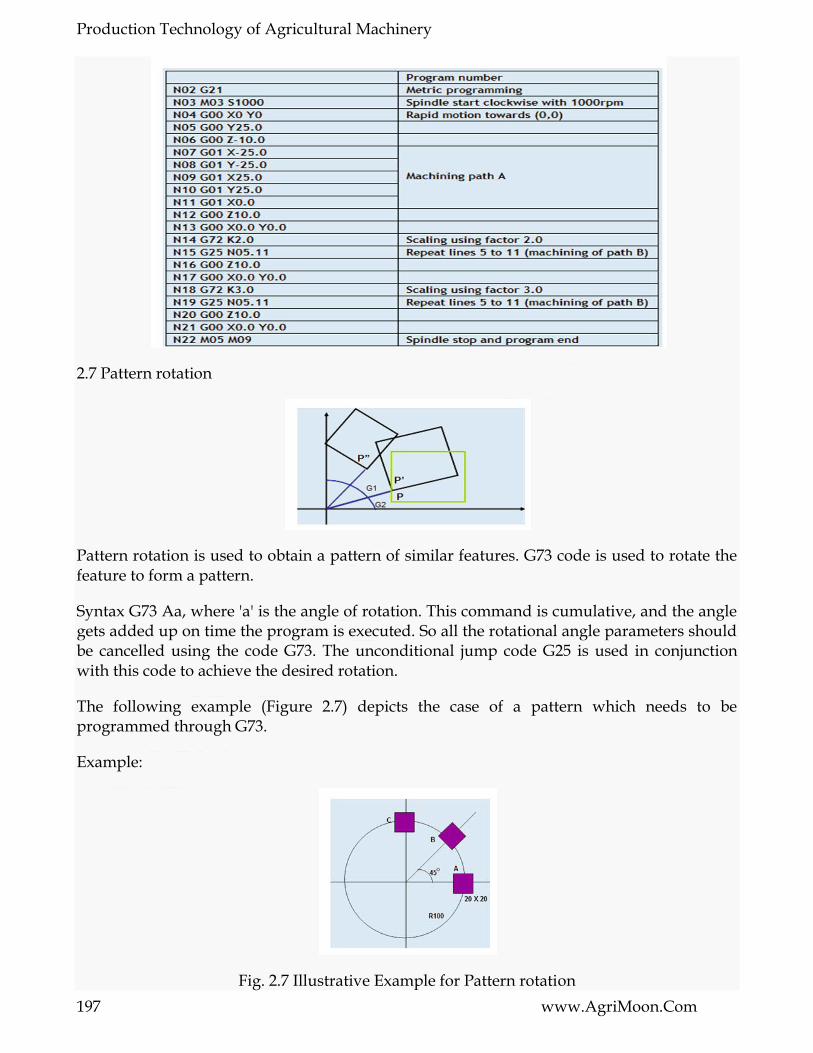
Production Technology of Agricultural Machinery
197 www.AgriMoon.Com
2.7 Pattern rotation
Pattern rotation is used to obtain a pattern of similar features. G73 code is used to rotate the feature to form a pattern.
Syntax G73 Aa, where 'a' is the angle of rotation. This command is cumulative, and the angle gets added up on time the program is executed. So all the rotational angle parameters should be cancelled using the code G73. The unconditional jump code G25 is used in conjunction with this code to achieve the desired rotation.
The following example (Figure 2.7) depicts the case of a pattern which needs to be programmed through G73.
Example:
Fig. 2.7 Illustrative Example for Pattern rotation

Production Technology of Agricultural Machinery
198 www.AgriMoon.Com
2.8 Tool selection
Tool selection is accomplished using 'T' function followed by a four digit number where, first two digits are used to call the particular tool and last two digits are used to represent tool offset in the program. The tool offset is used to correct the values entered in the coordinate system preset block. This can be done quickly on the machine without actually changing the values in the program. Using the tool offsets, it is easy to set up the tools and to make adjustments.
Feed rate control
Cutting operations may be programmed using two basic feed rate modes: 1. Feed rate per spindle revolution 2. Feed rate per time
The feed rate per spindle revolution depends on the RPM programmed.

Production Technology of Agricultural Machinery
199 www.AgriMoon.Com
LESSON 26. CNC PART PROGRAMMING III
3.1 Tool Radius Compensation
The programmed point on the part is the command point. It is the destination point of the tool. The point on the tool that is used for programming is the tool reference point. These points may or may not coincide, depending on the type of tool used and machining operation being performed. When drilling, tapping, reaming, countersinking or boring on the machining center, the tool is programmed to the position of the hole or bore center - this is the command point.
When milling a contour, the tool radius center is used as the reference point on the tool while writing the program, but the part is actually cut by the point on the cutter periphery. This point is at 'r' distance from the tool center. This means that the programmer should shift the tool center away from the part in order to perform the cutting by the tool cutting edge. The shift amount depends upon the part geometry and tool radius. This technique is known as tool radius compensation or cutter radius compensation.
In case of machining with a single point cutting tool, the nose radius of the tool tip is required to be accounted for, as programs are being written assuming zero nose radius. The tool nose radius center is not only the reference point that can be used for programming contours. On the tool there is a point known as imaginary tool tip, which is at the intersection of the lines tangent to the tool nose radius.
Cutter compensation allows programming the geometry and not the tool path. It also allows adjusting the size of the part, based on the tool radius used to cut part. This is useful when cutter of the proper diameter is not found. This is best explained in the Figure 3.1.
Fig 3.1. Cutter diameter compensation
The information on the diameter of the tool, which the control system uses to calculate the required compensation, must be input into the control unit's memory before the operation.
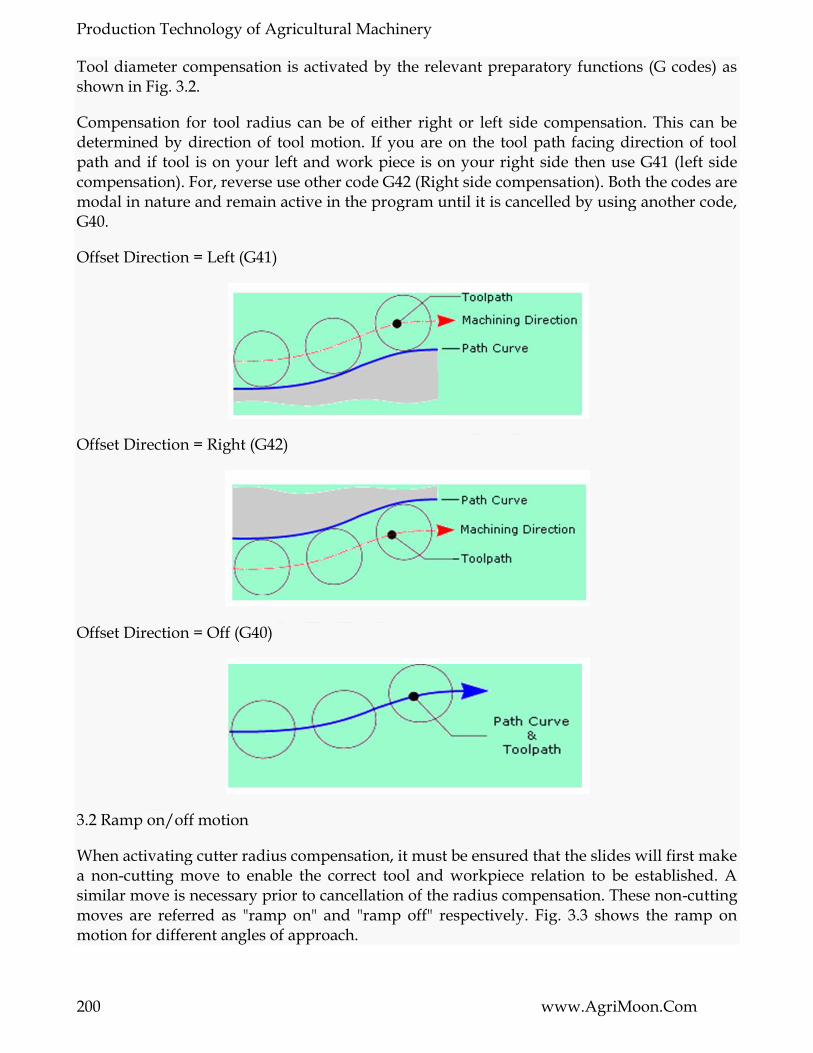
Production Technology of Agricultural Machinery
200 www.AgriMoon.Com
Tool diameter compensation is activated by the relevant preparatory functions (G codes) as shown in Fig. 3.2.
Compensation for tool radius can be of either right or left side compensation. This can be determined by direction of tool motion. If you are on the tool path facing direction of tool path and if tool is on your left and work piece is on your right side then use G41 (left side compensation). For, reverse use other code G42 (Right side compensation). Both the codes are modal in nature and remain active in the program until it is cancelled by using another code, G40.
Offset Direction = Left (G41)
Offset Direction = Right (G42)
Offset Direction = Off (G40)
3.2 Ramp on/off motion
When activating cutter radius compensation, it must be ensured that the slides will first make a non-cutting move to enable the correct tool and workpiece relation to be established. A similar move is necessary prior to cancellation of the radius compensation. These non-cutting moves are referred as "ramp on" and "ramp off" respectively. Fig. 3.3 shows the ramp on motion for different angles of approach.

Production Technology of Agricultural Machinery
201 www.AgriMoon.Com
Figure 3.3. Ramp up motion
3.3 Subroutines
Any frequently programmed order of instruction or unchanging sequences can benefit by becoming a subprogram. Typical applications for subprogram applications in CNC programming are
Repetitive machining motions
Functions relating to tool change
Hole patterns
Grooves and threads
Machine warm-up routines
Pallet changing
Special functions and others

Production Technology of Agricultural Machinery
202 www.AgriMoon.Com
Structurally, subprograms are similar to standard programs. They use the same syntax rules. The benefits of subroutines involve the reduction in length of program, and reduction in program errors. There is a definition statement and subroutine call function.
Standard sub-routine
N10
N20
N30
….
N70 G22 N5
N80
N90
….
N100 G24
….
N160 G20 N5
In the above example G22 statement defines the start block of the sub-routine and G24 marks the end of the sub-routine statement. The subroutine is called by another code G20 identified by the label N5.
Parametric subroutine
..
G23 N18
G01 X P0 Y P1
..
G21 N18 P0=k10 P1=k20
In the above example G23 starts the subprogram label and starts the definition, and the parameters P0, P1 are defined for values of x and y. The G21 statement is used to call the subroutine and to assign the values to the parameters.

Production Technology of Agricultural Machinery
203 www.AgriMoon.Com
3.4 Canned Cycles
A canned cycle is a preprogrammed sequence of events / motions of tool / spindle stored in memory of controller. Every canned cycle has a format. Canned cycle is modal in nature and remains activated until cancelled. Canned cycles are a great resource to make manual programming easier. Often underutilized, canned cycles save time and effort.
3.4.1 Machining a Rectangular pocket
This cycle assumes the cutter is initially placed over the center of the pocket and at some clearance distance (typically 0.100 inch) above the top of the pocket. Then the cycle will take over from that point, plunging the cutter down to the "peck depth" and feeding the cutter around the pocket in ever increasing increments until the final size is attained. The process is repeated until the desired total depth is attained. Then the cutter is returned to the center of the pocket at the clearance height as shown in fig. 3.4
Fig. 3.4 Pocket Machining
The overall length and width of the pocket, rather than the distance of cutter motion, are programmed into this cycle.
The syntax is : G87 Xx Yy Zz Ii Jj Kk Bb Cc Dd Hh Ll Ss (This g code is entirely controller specific and the syntax may vary between controller to controller).

Production Technology of Agricultural Machinery
204 www.AgriMoon.Com
Description:
x,y - Center of the part
z - Distance of the reference plane from top of part
i - Pocket depth
j,k - Half dimensions of the target geometry (pocket)
b - Step depth
c - Step over
d - Distance of the reference plane from top of part
h - Feed for finish pass
l - Finishing allowance
s – Speed
For machining a circular pocket, the same syntax with code G88 is used. 3.4.2 Turning Cycles
The G80 command will make the tool move in a series of rectangular paths cutting material axially until the tool tip reaches target point P1 where the cycle ends as shown in fig. 3.5. Cutting movements will be at the cutting feed rate. All other movements will be at rapid traverse rate.
Fig. 3.5 Turning Cycle (Straight cutting)
The syntax is G80 Xx Zz Ff
3.4.3 Roughing Cycle
In roughing cycle, the final finishing cycle profile is used to perform the roughing operation for the higher material removal rate. The syntax for the roughing cycle is given below.
G81 Pp Qq Uu Ww Dd Ff Ss

Production Technology of Agricultural Machinery
205 www.AgriMoon.Com
3.5 The APT Programming Language
The APT (Automatically Programmed Tool) programming language was developed in early 1960s to assist engineers in defining the proper instructions and calculations for NC part programming. A great strength of APT is its ability to perform precise calculations for complicated tool paths when contouring on a three dimensional surface in a multi- axis programming mode. Now APT has become obsolete. Please click here to know more about APT. Automatic generation of NC code is dealt in this page

******☺******
This Book Download From e-course of ICAR
Visit for Other Agriculture books, News,
Recruitment, Information, and Events at
www.agrimoon.com
Give FeedBack & Suggestion at [email protected]
Send a Massage for daily Update of Agriculture on WhatsApp
+91-7900 900 676
Disclaimer:
The information on this website does not warrant or assume any legal
liability or responsibility for the accuracy, completeness or usefulness of the
courseware contents.
The contents are provided free for noncommercial purpose such as teaching,
training, research, extension and self learning.
******☺******
Connect With Us: