production milling
TRANSCRIPT

8/13/2019 Production Milling
http://slidepdf.com/reader/full/production-milling 1/296

8/13/2019 Production Milling
http://slidepdf.com/reader/full/production-milling 2/296

8/13/2019 Production Milling
http://slidepdf.com/reader/full/production-milling 3/296

8/13/2019 Production Milling
http://slidepdf.com/reader/full/production-milling 4/296

8/13/2019 Production Milling
http://slidepdf.com/reader/full/production-milling 5/296

8/13/2019 Production Milling
http://slidepdf.com/reader/full/production-milling 6/296
8/13/2019 Production Milling
http://slidepdf.com/reader/full/production-milling 7/296
PRODUCTION MILLING

8/13/2019 Production Milling
http://slidepdf.com/reader/full/production-milling 8/296

8/13/2019 Production Milling
http://slidepdf.com/reader/full/production-milling 9/296
PRODUCTION
MILLINGA TREATISE DEALING WITH THE METHODS
EMPLOYED IN PROGRESSIVE AMERICAN
MACHINE SHOPS FOR OBTAINING QUANTITYPRODUCTION ON VARIOUS TYPES OF
MILLING MACHINES
BY
EDWARD K. HAMMONDASSOCIATE Eorroa OF MACHINERY
AUTHOR OF MODERN DRILLING PRACTICE, JOINT AUTHOR OF SHOP MANAGEMENT AND SYSTEMS
FIRST EDITION
FIRST PRINTING
NEW YORK
THE INDUSTRIAL PRESSLONDON: THE MACHINERY PUBLISHING CO., LTD
IQ2I
8/13/2019 Production Milling
http://slidepdf.com/reader/full/production-milling 10/296
-j o
COPYRIGHT, 1921 ,
BY
THE INDUSTRIAL PRESS
NEW YORK
COMPOSITION AND ELECTROTYPING BY THE PLIMPTON PRESS, NORWOOD, MASS., U.S.A.

8/13/2019 Production Milling
http://slidepdf.com/reader/full/production-milling 11/296
PREFACE
RECENT years have witnessed the introduction of many im-
proved methods of performing milling operations. On produc-
tion work, where high rates of output are essential, this result
has beenaccomplished
in various
ways, although mainly bya
reduction of the nonproductive time of the men and machines
in the milling department. In the preparation of this treatise,
the author's object has been the same as that of a member of
the planning department in a factory, who is called upon to
devise methods of milling and to design fixtures that will enable
repetition operations to be economically performed. Informa-
tion and illustrations relating to the latest developments in
production milling practice have been gathered by personal
studies of the methods used in many of the most progressive
manufacturing plants; and an acknowledgement is made to
the large number of factory executives who have cooperated
in carrying on this work. All of the methods discussed have
been successfully used under actual shop conditions.
It has been assumed that all mechanics reading this book
are familiar with the various types of production milling ma-chines. For that reason, only brief descriptions of the essential
features of each type of milling machine have been included.
It is the purpose of this book to explain the application of some
of the more efficient methods of operating milling machines on
repetition work, rather than to discuss milling machine design.
In connection with the examples of machining operations per-
formed on the various types of milling machines, information
is included covering the speed and feed at which each opera-
tion is performed and the rate of production that is obtained.
In a great majority of these cases, the stated output is close
to what would appear to be the maximum possible production
822420

8/13/2019 Production Milling
http://slidepdf.com/reader/full/production-milling 12/296
Vi PREFACE
for the job; therefore, these data should prove of value to
other manufacturers handling similar work, in checking uptheir results with a view to comparing them with those secured
by others. No attempt has been made to deal with work-
holding fixture design, beyond explaining certain fundamental
principles which must be observed to keep the ratio of loading
time to
cutting time down to a point where a satisfactory
output can be secured.
THE AUTHORS.
New York, January, 1921.

8/13/2019 Production Milling
http://slidepdf.com/reader/full/production-milling 13/296
CONTENTS
CHAPTER I
GENERAL TYPES OF MILLING MACHINES USED
ON PRODUCTION WORKPAGES
Rates of Production Automatic Millers Continuous
Rotary Millers Planer-type Millers Lincoln-type Millers
Knee-type Millers 1-8
CHAPTER II
PRODUCTION MILLING ON AUTOMATIC MACHINES
Feed Control Table Feed and Rapid Traverse Move-
ments Simultaneous Milling of Parts Sequence of Milling
Operations Time-saving Fixtures and Methods Work-
holding Fixtures Rates of Production. 9-75
CHAPTER III
CONTINUOUS ROTARY MILLING
Continuous Feed Means of Increasing Production
Range of Work Importance of Fixture Design RotaryFixtures on Horizontal- and Vertical-spindle Machines. . . . 76-129
CHAPTER IV
PLANER MILLING PRACTICE IN AUTOMOBILE
PLANTS
Multiple-spindle Machines Work-holding Fixtures
Three-point Suspension Cutting Speeds Adjustable Sup-
porting Points Simultaneous Milling of Different Parts
Divided-table Machine 130-170
vii

8/13/2019 Production Milling
http://slidepdf.com/reader/full/production-milling 14/296
viii CONTENTS
CHAPTER V
MILLING PRACTICE IN LOCOMOTIVE SHOPS PAGES
Slabbing and Channel-milling Operations Removal of
Metal from Large Castings 170-181
CHAPTER VI
STRING MILLING FIXTURES
Loading of Fixtures Reduction of Idle Time Simul-
taneous Performance of Operations Multiple Work-holdingFixtures Design of Fixtures 182-212
CHAPTER VII
INDEXING MILLING FIXTURES
Setting up Arbors Support for Arbors Types of Fix-
tures Standardized and Special Fixtures 213-244
CHAPTER VIII
OPERATIONS ON MACHINES OF RECIPROCATINGTYPE
Quantity Production of Duplicate Parts Standard
Designs Adaptedto
Special Requirements Time-savingDevices Quantity Production of Small work 245-263
CHAPTER IX
ECONOMY IN MILLING OPERATIONS
Equipment -Factor Direct Labor Cost Factor Tool
Cost Factor Quality Factor Manufacturing Costs in
Quantity Production 264-273

8/13/2019 Production Milling
http://slidepdf.com/reader/full/production-milling 15/296
PRODUCTION MILLING
CHAPTER I
GENERAL TYPES OF MILLING MACHINES USED ONPRODUCTION WORK
MILLING machines are'
employed for performing a great
variety of machining operations. Their range of application
extends from the most delicate kinds of precision work done
in the tool-room to the heavy-duty work of rapidly removingexcess stock from heavy castings and forgings. It is obvious
that there must be substantial differences in the designs of
milling machines used for such a wide variety of work, as well
as in the methods used for equipping and operating them for
different classes of milling operations. As implied by the title,
this treatise will deal with the subject of production milling
and contains, therefore, an explanation of the latest practice
in tooling and operating those types of machines that find
successful application in the quantity production of duplicate
parts. No space will be devoted to the discussion of tool-
room work or to an explanation of the methods of performing
milling operations where only one piece of work is set up on
the machine at a time.
Factors that Increase Rates of Production. Two of the
most important factors to consider in the performance of any
machining operation, including milling, where a high rate of
output is essential, are first, to make sure that the work is
done under conditions which closely approximate the maxi-
mum rates of speed and feed suitable for the particular case
under consideration, and second, to plan the method of opera-
tion so that the idle time for both the machine and its operator
is reduced to a minimum. There are various commonly
8/13/2019 Production Milling
http://slidepdf.com/reader/full/production-milling 16/296
, J2
'
PRODUCTION MILLING
used methods of obtaining these results, but one of the most
successful in the case of
production millingis to
employa
type of machine and a method of designing the work-holding
fixtures which will enable a number of pieces of work to be set
up so that they can all be milled by a single cut. The subse-
quent discussion will include detailed descriptions of the wayin which this principle has been applied to specific milling
operations; but as a general statement it may be said that the
setting up of a number of pieces of work simultaneously will
increase the rates of production by enabling the operator to
unload finished pieces while the milling operation is being per-
formed on other pieces of work. This not only reduces the
idle time of the operator by keeping him constantly employed,
but it also reduces the idle machine time, because the operator
usually has had time to remove most of the milled work from
the fixture when the last piece is completed.
General Types of Production Milling Machines. Millingmachines which find the most general application in American
manufacturing plants may be roughly divided into three general
classes as follows:
1. Automatic milling machines.
2. Continuous rotary milling machines.
3. Straight-line feed milling machines.
Each of these general classes may be further subdivided, so
that milling machines may be classified under the following
headings :
1. Automatic millers with straight-line feed movement.
2. Automatic millers with circular feed movement.
3. Automatic millers of the turret type.
4. Continuous rotary millers with the table rotating in a
horizontal plane.
5. Continuous rotary millers with the table rotating in a
vertical plane.
6. Standard millers with special rotary fixtures.
7. Planer-type millers.
8. Lincoln-type millers.
9. Knee-type millers with miltiple fixtures.

8/13/2019 Production Milling
http://slidepdf.com/reader/full/production-milling 17/296
TYPES OF MACHINES 3
Automatic Millers with Straight-line Feed Movement.
There are several different types of automatic milling ma-
chines equipped with tables that have a reciprocating straight-
line feed movement. The term automatic is usually applied
to this general type of milling machine although, strictly speak-
ing, it should be known as semi-automatic because, while
the feed movements are automatically controlled by tripping
dogs and suitable auxiliary mechanisms, it is necessary for the
operator to set up and remove the work by hand. On a
strictly automatic machine, both functions are mechanically
controlled. There are a number of possible combinations of
feed and rapid traverse movements for straight-line automatic
millers, and these will be described in detail in a subsequent
chapter; but at this time it may be mentioned that these
variations may include the employment of an intermittent
feed and rapid traverse movement for rapidly advancing the
work to the cutters and for performing the milling operations
at a suitable rate of feed, after which the table is rapidly tra-
versed back to the starting position. In some cases, such a
complex movement may not be desirable and in its place the
milling machine table simply feeds the work under the cutters
until the operation is completed, after which the feed move-
ment is automatically stopped and the table does not return
to the starting position until the operator manipulates a
hand-lever.
Automatic Millers with Circular Feed Movement. There
may be a number of different combinations for the arrange-
ment of feed movements on this type of milling machine, just
as there is a considerable difference in the arrangements of
straight-line machines with automatic control of the feed
movements. However, the usual method of operation is to
have the work-holding fixtures distributed around the cir-
cumference of the table, and if it is
possible
to
place adjacentpieces of work quite close together, there is no need of using
the automatic feature, because a uniform rate of feed is con-
stantly employed for passing the pieces of work under the
cutters. In some cases, however, there is considerable space

8/13/2019 Production Milling
http://slidepdf.com/reader/full/production-milling 18/296
4 PRODUCTION MILLING
between adjacent surfaces to be milled, and a serious loss of
time would occur through using the slow rate of feed for tra-
versing the table through the space that must be covered in
order to bring each successive piece of work into contact with
the cutters. In such cases, an automatic control is fre-
quently employed for alternately engaging the rapid traverse
movement and the feed movement, which results in quickly
bringing the work up to the cutters and then feeding it under
the cutters at the proper rate for the material that is being
milled.
Automatic Millers of Turret Type. It has been explained
that the purpose of simultaneously setting up more than one
piece of work is to enable both the operator and his machine
to be kept constantly employed. In the case of the turret
type of automatic milling machine, this result is accomplished
in a different way. Two parallel work-tables with straight-
line feed movements are mounted on anauxiliary turntable,
and while the pieces mounted on one table are being milled,
the operator is removing the finished pieces from fixtures on
the other table and mounting fresh blanks in their places.
Then, when the milling operation has been completed on
pieces carried by the table that is in the working position, the
auxiliary turntable or turret is indexed to bring the other table
into the operating position. Thus the only idle time for the
machine is the brief period that occurs while the table is being
indexed.
Continuous Rotary Millers with Table Rotating in Hori-
zontal Plane. On any type of continuous rotary milling
machine, the work is mounted in a continuous ring of fixtures
extending around the circumference of a circular table which
rotates to carry successive pieces of work under a single milling
cutter orbetween a pair
ofcutters, according to the require-
ments of the operation to be performed. After a machine of
this type has been set up and the tools adjusted to give the
required dimensions for the work, it is merely necessary for
the operator to stand at the front of the machine and devote
his entire time to removing machined pieces and setting up

8/13/2019 Production Milling
http://slidepdf.com/reader/full/production-milling 19/296
TYPES OF MACHINES 5
fresh blanks in their places as the table carries the fixtures
around to the loading position. Little mechanical skill is
required to operate a machine of this
type;
but as it is a
matter of general knowledge that the setting-up time for a
milling job may be greatly in excess of the actual milling
time, great care must be taken to design the clamping mechan-
isms on the fixtures in such a way that the time required to
remove finished pieces and set up fresh blanks is reduced as
far as possible.
Continuous Rotary Millers with Table Rotating in Vertical
Plane. Advantageous features of operation, which have
been explained in the preceding reference to continuous rotary
milling machines with horizontal tables, are all secured in
cases where a machine is equipped with a circular table ar-
ranged for rotation in a vertical plane. For handling some
classes of work, designers feel that it is more satisfactory to
have the table mounted in a vertical position. Certainly one
advantage is secured which may be of considerable importancein some cases, namely, that the chips of metal removed by the
milling cutters fall off by gravity and may be collected in a
container conveniently located for the laborer who comes
around at specified intervals and shovels the chips into a truck
to remove them from the machine shop.
Standard Millers with Special Rotary Fixtures. For
manufacturing plants which have a sufficient number of parts
to be milled so that one or more machines can be constantly
used on a single job, it will usually be found desirable to em-
ploy standard rotary milling machines for such operations,
rather than to use knee-type millers equipped with special
fixtures for applying the continuous rotary principle of mill-
ing. There are many shops, however, that are frequently
called upon to handle a job comprising a sufficiently large
number of duplicate parts so that it is a profitable investment
to have a rotary fixture to turn out such work whenever an
order is received. Special rotary fixtures may be used in
this way in jobbing shops specializing in contract work, and
the same Is true of many manufacturing plants of moderate

8/13/2019 Production Milling
http://slidepdf.com/reader/full/production-milling 20/296
6 PRODUCTION MILLING
size, which make a variety of products with only a moderate
output in each class of work. Insuch
factories, advantage
may be taken of the increased production obtained with con-
tinuous rotary machines through the application of these
special fixtures; and when there is no work for the continuous
rotary machine to do, the fixture may be removed in order
that the machine may be used as a standard knee-type
miller.
Planer-type Millers. The term planer type has come
to be quite generally employed for designating large-sized
milling machines on which it is usual to set up a string of
parts to be milled, arranged in a straight line along the table.
Recently, machines of this type have also come to be quite
generally known as multiple-spindle
milling machines
because they are generally equipped with both horizontal and
vertical spindles to provide for simultaneously milling two or
more surfaces on a piece of work. Some builders of this typeof miller make a practice of designing and building each ma-
chine to meet the special requirements of the job on which
it is to be used. This is done because machines of this type
generally represent a substantial investment and it is con-
sidered more economical to develop a special lay-out that
will make the machine ideally adapted for the work on which
it is to be continually employed, than to include expensive
mechanisms which would afford a wide range of speed and
feed changes and other adjustments to provide for handling
work of various kinds. Of course, this applies only to cases
where machines are especially designed and built for manu-
facturers who have a sufficient volume of work to keep each
miller constantly employed on a specified job. When milling
machines are so built, the customer generally sends a blue-
print of the piece to be milled and information concerning the
material of which it is made, the depth of cut to be taken,
the degree of accuracy that is required in the finished work,
and the number of pieces that must be milled per hour to
obtain the necessary daily output. With these data at his
disposal, the machine designer proceeds to lay out an equip-

8/13/2019 Production Milling
http://slidepdf.com/reader/full/production-milling 21/296
TYPES OF MACHINES 7
ment in which the milling machine builder's standard features
of construction are employed with suitable modifications to
produce the most economical machine that will give the de-
sired results. Planer-type milling machines are employed for
medium or large-sized work, and it is quite a general practice
to have a string of fixtures set up in a row along the table
which is usually of considerable size.
Lincoln-type Millers. In handling small and medium-
sized work, the Lincoln type of milling machine is generally
employed for the same classes of milling operations for whicha planer-type machine would be used if the work were of
larger size. These machines are often equipped with a string
of fixtures mounted in a row, so that advantage may be taken
of the reduction of idle time and the corresponding increase in
production that results from setting up a number of pieces
simultaneously. Also, as the rate of feed, depth of cut, and
other conditions of operation in handling production work are
usually severe, the Lincoln type of milling machine construc-
tion without the customary knee adjustment is said to possess
a greater degree of rigidity.
Knee-type Millers with Multiple Fixtures. In progressive
manufacturing plants where advantage is taken of every pos-
sibility of increasing rates of production and reducing unit
costs, various types of multiple work-holding fixtures are em-
ployed on knee-type milling machines. In every case, the
purpose is to reduce the idle time to a minimum. One of the
commoner methods of equipping such millers is to arrange a
string of fixtures in a row along the table. Successful results
are also secured by the so-called twin-fixture principle, where
two fixtures of similar design are mounted at opposite ends of
the table so that, after the milling operation has been per-
formed on apiece
held in onefixture,
theposition
of the table
is reversed to bring the work held in the fixture at the opposite
end of the table into contact with the cutters; then, while the
milling operation is being performed on this second piece, the
operator removes the milled piece from the first fixture and
sets up a fresh blank in its place. Another successful method
8/13/2019 Production Milling
http://slidepdf.com/reader/full/production-milling 22/296
8 PRODUCTION MILLING
of
equippingknee-type millers is to use turret fixtures which
are mounted on a pivotal support with means of indexing and
locking the fixture in either of two positions, so that work
held at one side of the fixture may be milled while the opera-
tor is removing the finished part from the opposite side and
setting up a fresh blank in its place. It is often possible to
use twin indexing fixtures of this type with unusually success-
ful results.

8/13/2019 Production Milling
http://slidepdf.com/reader/full/production-milling 23/296
CHAPTER II
PRODUCTION MILLING ON AUTOMATIC MACHINES
INDUSTRIAL plants engaged in the manufacture of products
on which there are large numbers of small or medium-sized
parts to be milled, find that these repetition milling operations
can beadvantageously performed
on automaticmilling
ma-
chines. There are several millers of this general type built
for the market, all of which are furnished with automatic
control for the feed movement, in order to make it unnecessary
for the operator to give his time to this part of the work. As
a result, it is possible for one man to look after two or more
machines, thus effecting a substantial reduction in the labor
cost which must be charged against a job; this cutting down
of the cost of labor, however, is not the only reduction of
manufacturing costs which is made possible by the use of
automatic milling machines under the most advantageous
conditions of operation.
Automatic Control of Feed Movements. Owing to the
variety of arrangements of control which have been devised
by the designers of different types of automatic millers, definite
information as to the way in which savings in manufacturingcosts are effected cannot be presented except in those sections
of this chapter which deal with features of the different types
of machines. At this time, however, a general statement can
be made that the automatic control of the feed movement on
milling machines of this type is the means of reducing idle
time of the machine in traversing across the space from one
piece of work to the next in cases where a number of parts
are set up in a string fixture, in returning the table to the
starting point at high speed after the cut has been completed,
and through the application of similar time-saving methods of
operation. The term automatic millers is generally applied
9

8/13/2019 Production Milling
http://slidepdf.com/reader/full/production-milling 24/296
IO PRODUCTION MILLING
to machines of this type, but they would be more properly
designated as semi-automatic millers, because, although the
feed movements of the table are mechanically controlled, the
operator is required to set up the work and remove the milled
parts. A machine cannot be properly described as auto-
matic unless both of these functions are performed by mech-
anism, as in the case of automatic screw machines.
Cincinnati Automatic Plain Milling Machine. It is pro-
posed first to present a brief description of the essential features
of each type of machine, and then to illustrate and describe
some examples of practice in the performance of milling opera-
tions. The Cincinnati Milling Machine Co. builds an auto-
matic plain miller in three different sizes, which have a table
traverse of 12, 18, and 24 inches, respectively. Machines of
each of these sizes are made in single and duplex styles, accord-
ing to the requirements of the work on which the machine is to
be used. Aside from differences in size, whether the machineis equipped with one or two spindles, the features of all of
these machines are the same.
In consideration of the fact that these tools are to be used
on production work, the design has been made as simple and
rigid as possible. All unnecessary slides have been eliminated,
and there is no saddle, the table resting directly upon the
bed. A stream lubrication system forms a part of the regular
equipment of each machine, in order that the cutters and
work may be thoroughly cooled when the machine is taking
the heaviest cut of which it is capable. On a machine that is
to be used continuously on the same job, provision for obtain-
ing any of a number of different speeds is not a matter of
importance; it is merely necessary to provide for driving the
spindle at that speed which is suitable for the work on which
the machine is engaged. Hence, these millers are designed in
such a way that the purchaser may specify any one of twenty-
four spindle speeds, covering a range of from 31 to 603 revolu-
tions per minute. It is important to note, however, that the
gears which furnish this one speed may be reversed to provide
an additional speed; and should it happen that at some later

8/13/2019 Production Milling
http://slidepdf.com/reader/full/production-milling 25/296
AUTOMATIC MACHINES II
date the machine is to be used on another job requiring a
different speed, it will be an easy matter to order suitable
gears to adapt the miller for this new job.
Arrangement of the Automatic Feed Mechanism. These
milling machines are so arranged that at the end of the feed
movement of the table a dog will automatically disengage the
spindle clutch and apply a brake to stop the spindle at the time
that the direction of table travel is automatically reversed, so
that the table returns to its starting position with the cutter
stationary. Two advantages are obtained from this condi-
tion of operation, namely, provision is made for the safety of
the operator, and the quality of the finished work is improved.
When the nature of the work does not require the use of this
feature, the automatic spindle stop may be easily disengaged.
The feed mechanism is so arranged that any of twelve rates
of feed may be selected, according to the requirements of
the work. As in the case of provision made for selecting
a suitable spindle speed, the continuous operation of these
machines on a single class of work makes it unnecessary to
provide means for obtaining any of a number of feed changes.
Attention is called to the fact, however, that the arrangement
of feed gears is similar to those that provide for driving the
spindle; namely, that where any one rate of feed is specified,
reversing the feed gears enables an additional rate of feed to
be obtained. The twelve feeds from which a selection can be
made cover a range from 1.09 to 18.3 inches per minute.
Combinations of Table Feed and Rapid Traverse Move-
ments. --There are a number of different combinations of
intermittent table feed and rapid traverse movements which
may be used on a machine of this type. The machine table
is provided with two dog slots, one controlling the rapid tra-
verse and one, the feed traverse; thus by setting dogs in these
two slots, it is possible to shift from the feed used while cut-
ting to the rapid traverse as often as may be desirable, and
also to reverse by rapid traverse. The fast power traverse is
at the rate of 100 inches per minute, and is used for returning
the table to its starting position after completing the forward

8/13/2019 Production Milling
http://slidepdf.com/reader/full/production-milling 26/296
12 PRODUCTION MILLING
movement; the fast traverse is also utilized in cases where a
string of parts is set up on the table and it is required to movethe table rapidly across the spaces between adjacent parts
which are to be milled. The use of a fast power traverse for
moving rapidly across the gaps between successive pieces of
work and for quickly returning the table to the starting point
is the means of effecting a substantial reduction in the non-
productive time of the machine.
QUICK RETURN

8/13/2019 Production Milling
http://slidepdf.com/reader/full/production-milling 27/296
AUTOMATIC MACHINES
vided on the machine, after which the spindle is stopped, the
table movement reversed, and the fast traverse movement en-
gaged to return the table to the starting point at 100 inches
per minute with the spindle stationary. The second com-
monly used cycle of table movements is indicated at C. It
consists of traversing the table forward at 100 inches per
minute, feeding across the work, again traversing the table
forward at 100 inches per minute until the work clears the
cutters, and finally stopping both the feed movement and
Fig. 2. Milling Two T-slots in the Work-head Spindle Carrier
for a No. 1 Grinding Machine
rotation of the spindle. When the work is removed, the table
is traversed back to the starting point by shifting a lever on
the feed-box by hand.
In operating under the conditions indicated at A and C,
stopping of the spindle is automatically accomplished bytripping the feed mechanism and applying a brake to the
spindle. After the work has been set up, manipulation of
the main starting lever provides for engaging both the table
movement and spindle drive. Owing to the interlocking
mechanism, it is impossible to engage the feed without start-

8/13/2019 Production Milling
http://slidepdf.com/reader/full/production-milling 28/296

8/13/2019 Production Milling
http://slidepdf.com/reader/full/production-milling 29/296

8/13/2019 Production Milling
http://slidepdf.com/reader/full/production-milling 30/296
i6 PRODUCTION MILLING
bolt bosses on the forgings. At the small end of each piece of
work there is a V-block E, in which the groove is placed at
right angles to the direction of the table travel, and a bolt F
clamps block G down on the work, in order to secure it in
V-block E. These V-blocks E serve the additional purpose of
supporting the end thrust of the cutters. It will be evident
that at the top of both bolts D and F there are sliding pins bywhich these bolts may be turned in order to clamp the work
Fig. 4. Simultaneously milling Clearance Spaces between Bolt
Bosses at Both Sides of Connecting-rods
in the fixture. The clamping mechanism is, of course, iden-
tically the same at the rear ends of the two pieces of work,
which are in the milling position as they are shown in Fig. 3.
Setting up Connecting-rod Forgings. In setting up con-
necting-rod forgings in this fixture, the method of procedure is
as follows: The operator places a forging in each side of the
fixture, and then tightens the clamps on the forging at the
left-hand side of the fixture as shown in Fig. 3. After this has
been done, the feed is engaged and the operator then proceeds

8/13/2019 Production Milling
http://slidepdf.com/reader/full/production-milling 31/296
AUTOMATIC MACHINES IJ
to tighten the clamps on the forging at the right-hand side of
the fixture. The reason for following this procedure is that the
length of cut on the crankpin bearingis
substantially greaterthan that required on the wrist-pin bearing, so that sufficient
time is allowed after the cut has been started at the large end
of the work, held at the right-hand side of the fixture, to en-
able the operator to tighten the clamps on the second forging
before the cutters come into engagement with the small end
of this forging which is held at the left-hand side of the fix-
ture. Such a method is the means of substantially reducing
the idle time of the machine, and enables a higher rate of
production to be obtained. On -this job, the work is fed to
the cutters at the rate of 2.4 inches per minute, and the cut-
ting speed is 204 feet per minute. The rate of production
obtained is forty finished connecting-rods per hour. The
cycle for the automatically controlled feed movement of the
table is as follows: Traverse work to cutters at 100 inches
per minute, feed work across cutters at 2.4 inches per minute,
trip feed, stop rotation of spindle, reverse movement of table,
and finally traverse the table back to the starting point at
100 inches per minute.
Milling Clearance Spaces between Bolt Bosses of Connect-
ing-rods. Figure 3 shows an automatic duplex miller set up
with the two opposed spindles at the same level, so that two
pairs
of cutters can be used to straddle-mill the ends of two
forgings that are also held at the same level. It will be
apparent from the illustration of the machine, however, that
adjustment is provided for the two spindle heads, so that
they may be placed either at the same level or with one spindle
at a greater elevation than the other. This independent ad-
justment of the two spindle heads can often be successfully
utilized to provide a more economical method of milling than
would otherwise be possible. A case in point is shown in
Fig. 4, which illustrates a good example of the way in which
a Cincinnati automatic duplex milling machine may be ar-
ranged with the spindle heads at different levels, in order to
provide for simultaneously milling the top and bottom sides
8/13/2019 Production Milling
http://slidepdf.com/reader/full/production-milling 32/296
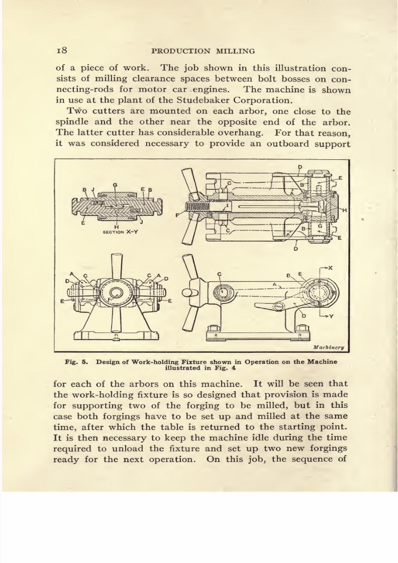
i8 PRODUCTION MILLING
of a piece of work. The job shown in this illustration con-
sists of milling clearance spaces between bolt bosses on con-
necting-rods for motor car engines. The machine is shown
in use at the plant of the Studebaker Corporation.
Two cutters are mounted on each arbor, one close to the
spindle and the other near the opposite end of the arbor.
The latter cutter has considerable overhang. For that reason,
it was considered necessary to provide an outboard support
Machinery
Fig. 5. Design of Work-holding Fixture shown in Operation on the Machine
illustrated in Fig. 4
for each of the arbors on this machine. It will be seen that
the work-holding fixture is so designed that provision is made
for supporting two of the forging to be milled, but in this
case both forgings have to be set up and milled at the same
time, after which the table is returned to the starting point.
It is then necessary to keep the machine idle during the time
required to unload the fixture and set up two new forgings
ready for the next operation. On this job, the sequence of

8/13/2019 Production Milling
http://slidepdf.com/reader/full/production-milling 33/296
AUTOMATIC MACHINES 19
rapid traverse, feed, and quick return movements of the table
is the same as described for the previous milling operation.
The rate of production obtained is sixty forgings per hour,which represents the time from floor to floor.
Design of Fixture Used in Milling Operation. The fixture
used on this machine represents quite an interesting example
of tool design; Fig. 5 shows the construction in detail. It
will be seen that the two connecting-rod forgings A are located
by means of arbors B which enter the finished crankpin bear-
ings, while at the opposite end short arbors C enter the wrist-
pin bearings to prevent the work from turning on arbors B.
Two slotted latches D are dropped over the heads of the clamp-
ing members E that slide inside the hollow mandrels B; and
it will be apparent that while the heads of clamps E are made
of such a size that the crankpin bearings will pass over them,
the latches are large enough to hold the work on the arbors,
after they have been dropped into place. The final step in
clamping the work is accomplished by turning a capstan
wheel which fits on the threaded end of draw-bolt F. At its
opposite end, this draw-bolt has a tapered head G, which en-
gages corresponding tapers H at the ends of clamping mem-
bers E.
The manner in which these clamping members are cut
away so that they overlap each other is best shown in the
cross-sectional view on the line X-Y. It will be evident that
when draw-bolt F is pulled back by turning the capstan wheel,
it causes the tapered head G at the opposite end of this bolt
to engage the tapers H and pull the two clamping members
E inward, thus drawing their heads firmly against the latches
D that secure the connecting-rod forgings in place on arhors
B. After the milling operation has been completed, and it is
desired to unload the fixture, the capstan wheel is loosened
and compression spring 7 pushes back draw-bolt F, so that its
hold on the clamps E is released. Two compression springs J
are then able to push clamps E outward, so that the latches
D are released and may be swung upward to allow the forgings
to be lifted out of the fixture. The detailed description neces-
8/13/2019 Production Milling
http://slidepdf.com/reader/full/production-milling 34/296
2O PRODUCTION MILLING
sary to explain the features of design of this fixture may make
the method of
loading
andunloading
the fixture
appearrather
complicated. As a matter of fact, this is not the case, as the
forgings can be set up or removed by simply giving a turn to
the capstan wheel at the end of the draw-bolt F, and then
lifting up the two latches D, if the fixture is to be unloaded;
or dropping these two latches D into place, and then turning
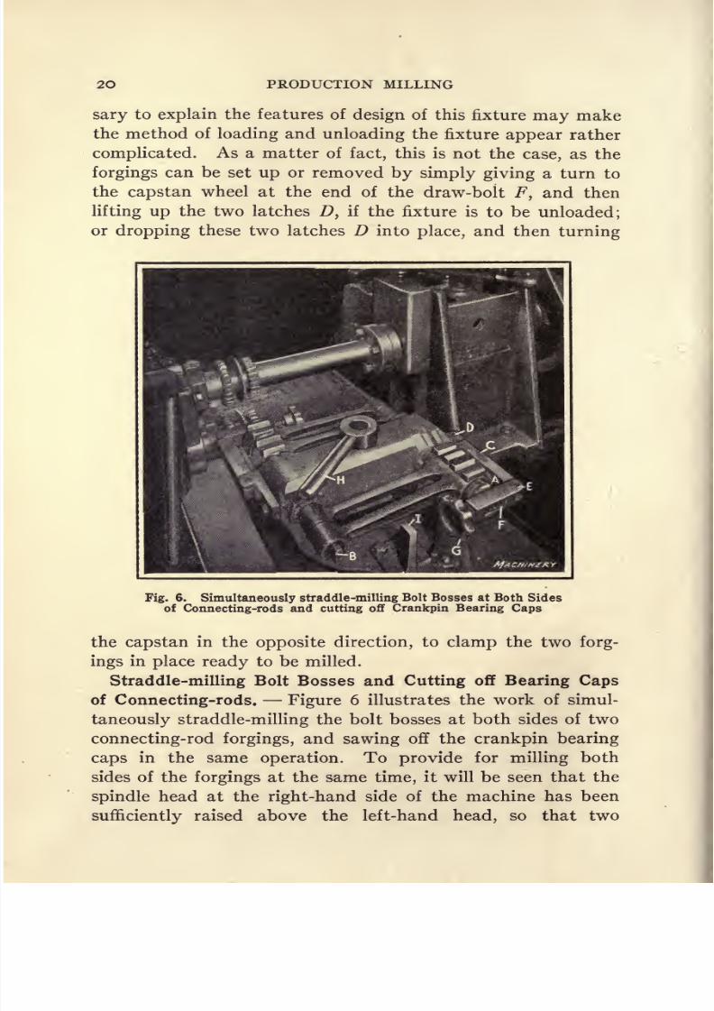
Fig. 6. Simultaneously straddle-milling Bolt Bosses at Both Sides
of Connecting-rods and cutting off Crankpin Bearing Caps
the capstan in the opposite direction, to clamp the two forg-
ings in place ready to be milled.
Straddle-milling Bolt Bosses and Cutting off Bearing Caps
of Connecting-rods. Figure 6 illustrates the work of simul-
taneously straddle-milling the bolt bosses at both sides of two
connecting-rod forgings, and sawing off the crankpin bearing
caps in the same operation. To provide for milling both
sides of the forgings at the same time, it will be seen that the
spindle head at the right-hand side of the machine has been
sufficiently raised above the left-hand head, so that two

8/13/2019 Production Milling
http://slidepdf.com/reader/full/production-milling 35/296
AUTOMATIC MACHINES 21
pairs of cutters may be used to simultaneously straddle-mill
the ends of the bolt bosses at opposite sides of the forgings.
Located on the arbor between each pair of straddle-milling
cutters, there is a small slitting saw which provides for cutting
off the bearing caps at the same time the milling operation is
performed. It will be noticed that the cutters which work
at the top of the forgings are located on their arbor at a con-
siderable distance from the spindle; and to avoid springing
this arbor, an outboard support has been provided for it on
the cutter-head at the left-hand side of the machine.
Application of Time-saving Fixtures on Automatic Machines.- The milling operation shown in Fig. 6 represents an ad-
vantageous combination of equipment for obtaining rapid
production, because not only is the machine provided with
automatic control for the feed and rapid traverse movements
of the table, but an indexing type of fixture has also been pro-
vided, which enables the operator to remove the milled forg-
ings and substitute fresh blanks in their place, while the cut
is being taken on two forgings held at the opposite side of the
same fixture. This might be termed an indexing type of string
fixture, because at each station two forgings are set up in line,
so that a cut may be taken on both of them before it is neces-
sary to return the table and index the fixture ready for the
next cut.
It will be evident that the two forgings carried at each
side of this fixture are located by means of mandrels A and
Bj which are a close fit in the crankpin and wrist-pin bear-
ings, respectively. In designing this fixture, provision had
to be made for supporting the two forgings at their large
ends in such a way that the crankpin bearing caps would
be prevented from falling off mandrel A and getting damaged
bythe saws and cutters after the
slittingsaws have
cut themoff from the forgings. This result is accomplished by the
clamping bar C which is supported by a pivot- Z>, so that it
may be swung into place against the ends of the forgings.
This bar C is secured by a pivoted link E which is slotted to
fit over a small projection F on the end of the mandrel A.
8/13/2019 Production Milling
http://slidepdf.com/reader/full/production-milling 36/296
22 PRODUCTION MILLING
When it has been located in this position, clamping is ac-
complished by turning a small handwheel G, which manipu-lates a screw that is threaded into the end of link E, so that
it may bind against the side of the projection F that passes
through the opening in this link. In indexing the fixture, it
is merely necessary to loosen the main binding screw H and
release latch 7; then after the fixture has been turned through
180 degrees, the latch enters a notch in the opposite side, after
which binder H is
tightened,
and the fixture is in
position
for
milling the next two forgings.
Sequence of Automatic Feed and Rapid Traverse Move-
ments. The sequence of automatically controlled feed and
rapid traverse table movements used on this job is quite
simple. It is merely a case of rapidly advancing the table to
bring the work up to the cutters, after which the quick move-
ment is -tripped and the feed automatically engaged. Then
when the work has been fed across the cutters, a dog disen-
gages the feed, reverses the direction of table movement, and
stops the rotation of the spindles, after which the table is tra-
versed back to the starting point at high speed. Then the
fixture is indexed to bring the next two forgings into the
operating position, and the same sequence of movements is
repeated, this cycle of operations being continued indefinitely,
withvery
little idle time on thepart
of either the machine or
its operator. On this job, the rate of production obtained is
seventy forgings per hour, which represents the time from
floor to floor.
Facing Seat for Crankpin Bearing Cap on Connecting-rods.
The automatic miller shown in Fig. 7 is used for facing the
crankpin bearing cap seat on motor car engine connecting-
rods. This is another example of a case in which the two
spindle heads of a duplex machine are placed at different
levels. But in this instance it is not necessary to have such
a marked difference in the elevation of the two spindles, as in
the cases shown in Figs. 4 and 6, because it is only required
to have the cutters carried by the two spindles reach the
faces of two connecting-rod forgings that are held one above

8/13/2019 Production Milling
http://slidepdf.com/reader/full/production-milling 37/296
AUTOMATIC MACHINES 23
the other on each station of the indexing fixture. The se-
quence of movements is as follows: Rapidly traverse the
table to bring the work up to the cutters, feed the work across
the cutters, automatically reverse the direction of table move-
ment, stop the spindle, and rapidly traverse the table back to
the starting point.
Features in Design of Fixture for Milling Bearing Caps.
There are several interesting features in the design of the
Fig. 7. Milling Seat for Crankpin Bearing Caps on
Connecting-rods
fixture shown in this machine. In setting up two forgings oneither of the stations, the finished wrist-pin bearings are slipped
over pins Ayeach of which is carried on a slide B. At its
crankpin end, each forging fits over a half-round block C, but
at the time it is placed in the fixture the forging does not
come firmly into contact with this block. After the two

8/13/2019 Production Milling
http://slidepdf.com/reader/full/production-milling 38/296
24 PRODUCTION MILLING*
pieces to be milled have been put into place in this fixture,
capstanwheel D is
turned,with the result that it rocks link E
about the pivotal support on which this link is carried. Link
E is also pivoted to each of the slides B, and as it is moved by
turning handwheel D, link E causes the two slides B and
pins A carried by them, to move in opposite directions, thus
clamping the crankpin ends of the two connecting-rods firmly
against the half-round blocks C. The work projects sufficiently
beyond these blocks C to allow the ends of the yoke to be
milled.
In the position in which the milling operation is performed,
the thrust of the cutters on the work is back against the body
of the fixture, so that there is no tendency for the forgings to
slide off their locating pins A and blocks C. Aside from the
special means provided for holding the work, this indexing
fixture does not call for a detailed description, because it is of
a standard type whichwill
be more fully dealt within
a later
chapter discussing the design and use of indexing milling fix-
tures. But at this time it may be stated that to release this
fixture ready for indexing, it is merely necessary to manipu-
late the lever F; and after the fixture has been indexed through
180 degrees, swinging this lever in the opposite direction
clamps the fixture in place ready for the next cut to be taken.
The rate of production on this job is one hundred connecting-
rods per hour, which represents the time from floor to floor.
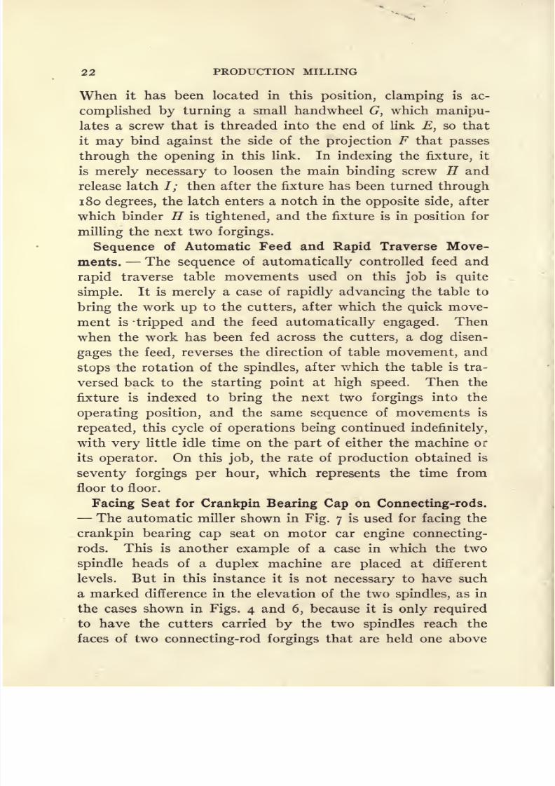
Facing the Base of Crankpin Bearing Caps for Connecting-
rods. The milling operation illustrated in Fig. 8 is similar
to the one which has just been described. This job consists
of milling the base of crankpin bearing caps that fit on the
seats milled on the rods during the preceding operation. The
fixture used is also provided with a clamping lever A that
serves the double purpose of accurately locating the fixture
in the desired position and then providing means for clamp-
ing it in place while the cut is being taken. It merely remains
to describe the method of holding the bearing caps in place on
the fixture while they are being milled. As in the preceding
case, there are two half-round blocks B on each station of the
8/13/2019 Production Milling
http://slidepdf.com/reader/full/production-milling 39/296
AUTOMATIC MACHINES 25
fixture, against which the two bearing caps are clamped.
These caps C are clamped against blocks B by means of V-
blocks D that engage the under sides of the bolt bosses on
bearing caps C. The two V-blocks D are threaded right- and
left-hand respectively, so that they may be forced in opposite
directions by means of a right- and left-hand screw which is
turned by means of a handle E that may be slipped into any
Fig. 8. Milling Base of Crankpin Bearing Caps for Connecting-rods
of the holes in hub F. On this job the rate of production
obtained is one hundred caps per hour. The same sequenceof feed and traverse movements of the table is used as in the
preceding operation on connecting-rods.
Milling Base of Differential Bearing Caps. Figure 9
shows an 18-inch automatic miller set up for milling the base
of differential bearing caps for motor cars. It will be evident

8/13/2019 Production Milling
http://slidepdf.com/reader/full/production-milling 40/296
26 PRODUCTION MILLING
that the two spindle heads are placed at the same level, so
that a cutter carried by each spindle may be utilized to mill
off the faces of one of the bearing caps. An indexing milling
fixture is used for holding these castings, which is so designed
that two pieces are held in position to be milled; and while
the operation is being performed on these two parts, two other
Fig. 9. Milling Base of Differential Bearing Caps. An IndexingFixture holds the Work
finished pieces may be removed from the opposite station of
the fixture and fresh castings set up in their places. This
milling operation consists of facing off two surfaces A on each
of the bearing caps, and as there is a space of about four inches
between these two surfaces, dogs are arranged on the milling
machine table to provide for first traversing the table at a
rate of 100 inches per minute, to bring the work up to the
cutters. Then a
dog trips
therapid
traverse andengages
the
feed movement, to mill the first face A. After this has been
done, the rapid traverse is again utilized to move the table
across the space between the two surfaces A, after which the
feed movement is once more engaged automatically for milling
the second surface on the work. At this point, another dog

8/13/2019 Production Milling
http://slidepdf.com/reader/full/production-milling 41/296
AUTOMATIC MACHINES 27
disengages the feed, stops the spindle, and reverses the direc-
tion of table movement, after which the table is returned to
the starting point at high speed.
After two bearing caps held at one side of this indexing
fixture have been milled, pin B is withdrawn and handle C
is turned to release the binder that clamps the fixture in place
during the time that the cut is being taken. The fixture is
then indexed through 180 degrees, and after pin B has again
located it in the desired position, handle C is turned in the op-
positedirection to
reclampthe fixture. At each
station,it
will be noticed that there are two half-round blocks D which
engage the under side of the lugs at each side of the differen-
tial bearing-cap castings, in order to locate them in position
for milling. At each station there is also a pin E, against
which the end of the casting is placed in order that this pin
may support the thrust exerted by the milling cutters. The
casting is held down in the fixture by a pivoted clamp F, and
when it is desired to remove the milled casting, this clamp is
released by first loosening bolt G about a half turn, and then
swinging slotted latch H about the pivot which holds it on
strap F. There is a hole in strap F of sufficient size to pass
the nut on bolt G. This arrangement allows the clamp to be
released by simply making a half turn of the nut, and is the
means of saving a great deal of time in loading and unloading
the fixture. On this job, the rate of production obtained is
one hundred finished bearing caps per hour.
Milling Grooves in Typewriter Key Lever Brackets.
Previous descriptions of automatic millers have shown the
application of machines provided with two spindles. Figure 10
shows an example of production milling on a single-spindle
automatic miller. It is used at the plant of the Royal Type-
writer Co. for milling a groove in the key lever bracket for a
typewriter. The work is cast iron, and ordinarily no special
provision would have to be made for cooling the cutters and
work. In this case, however, the cutters are engaged in mill-
ing a groove J inch wide by f inch deep, and, as they are in
contact with both the bottom and sides of this groove during

8/13/2019 Production Milling
http://slidepdf.com/reader/full/production-milling 42/296
28 PRODUCTION MILLING
the entire time that the cut is being taken, there is very little
opportunity to dissipate the heat generated by the cut. As a
result, it was considered necessary to provide means for cooling
the cutters, and the use of a blast of cool air was finally adopted
for this purpose. It will be seen that at each side of both
of the cutters there is a hood A in which holes have been
drilled on the inner side. These hoods are connected with
a compressed air line, so that while the machine is in opera-
tion, a stream of cool air is constantly striking against the cut-
Fig. 10. Automatic Milling Machine with Air-cooled Cutters for
performing Grooving Operation
ters. The application of this air blast to the cutters also
serves the additional purpose of blowing away the chips, so
that the cutting action is not retarded.
The dogs are set to traverse the table rapidly in order to
bring the work up to the cutters, after which the feed is auto-
matically engaged to pass the two castings under the mill-
ing cutters. After the cut has been completed, the spindle
is stopped, the direction of table movement reversed, and
the table is returned to the starting point at the high traverse

8/13/2019 Production Milling
http://slidepdf.com/reader/full/production-milling 43/296
AUTOMATIC MACHINES 29
speed. It has already been stated that the grooves in these
key lever brackets are J inch wide by f inch deep, and the
length of the groove is 13 inches. The rate of feed em-
ployed is 8.3 inches per minute, and the cutters, which are
2\ inches in diameter, are driven at a speed of 135
revolutions per minute, which corresponds to a cutting speed
of 97 feet per minute. The rate of production obtained on
this job is 450 milled key lever brackets in a nine-hour working
day.
Design of Fixture for Milling Key Lever Brackets. Thefixture in which two key lever brackets are held for the groove
milling operation is designed to facilitate the work of setting
up these parts, as far as possible. The location is obtained
from the milled under side of the work, and the pieces are
held down in the fixture by means of a lug B at each end.
At the rear of the fixture, there is a bar C under which one of
thelugs
B on the work is
slipped.
Then apivoted strap
Dis clamped down on the lug at the front end of the work.
This strap D is secured by the nut on a bolt, this nut being
small enough to pass through the hole in strap D. A pivoted
C-washer F is swung into place under the clamping nut at the
time that the work is being secured in the fixture. Sidewise
location and clamping of the work is accomplished by means
of four knurled-head screws G. These screws engage the sides
of the work at each end, and press them inward against a
center stop on the fixture.
Milling V-slots in Steel Rings. Figure 1 1 shows another
single-spindle automatic milling machine which is engaged in
machining a row of pieces mounted in a string fixture. The
operation performed on this machine consists of milling a
V-slot across the top of a steel ring, and the string fixture is
designed to hold six pieces of work. The material is low-
carbon steel and it will be seen that the cut is taken by a special
angular cutter with staggered teeth. The rings are if inches
in diameter with walls J inch thick; and the slots to be milled
are A inch deep by |f inch wide at the top and \ inch wide
at the bottom. The cutter is made of high-speed steel; it is

8/13/2019 Production Milling
http://slidepdf.com/reader/full/production-milling 44/296
30 PRODUCTION MILLING
3^ inches in diameter and runs at 103 revolutions per minute,
which gives a cutting speed of 94 feet per minute. The rate
of feed is 3.87 inches per minute, and the actual production
time from floor to floor is i.i minutes for each piece; that is
to say, the hourly rate of production is fifty-four and one
half pieces. For performing this operation, the dogs which
automatically control the feed and traverse movements of
Fig. 11. Automatic Milling Machine equipped with String Fixture for
milling V-slots
the table are so arranged that the cycle is as follows: Traverse
the work to the cutter, feed the six pieces under the cutter,
stop the spindle, reverse the direction of table movement, and
rapidly traverse the table back to the starting point.
Cincinnati Plain Manufacturing Milling Machine. There
is a small machine of the column and knee type built for mill-
ing large numbers of small or medium sized duplicate parts.
It is a simple manufacturing miller equipped with a single-

8/13/2019 Production Milling
http://slidepdf.com/reader/full/production-milling 45/296

8/13/2019 Production Milling
http://slidepdf.com/reader/full/production-milling 46/296
PRODUCTION MILLING
moved forward as rapidly as possible without the need of slow-
ing down as the work approaches the cutters, because the
table dog automatically engages the power feed at the proper
time, without any need of observing special precautions.
This effects a substantial saving in time and production cost.
With the dogs properly set, the actual feeding distance is also
Fig. 12. Manufacturing Milling Machine equipped with String Fixture
for milling Rack Teeth in Index-pins
reduced to slightly over the actual amount required to tra-
verse the work past the cutters.
Milling Index-pin for Front Plate of Universal Dividing
Head. Figure 12 shows one of the 1 2-inch manufacturing
millers employed for milling rack teeth in index-pins for the
front plate of lo-inch universal dividing heads. There are
five 24-pitch teeth to be milled, which have a face width of
| inch. The material is machine steel, and it will be seen that

8/13/2019 Production Milling
http://slidepdf.com/reader/full/production-milling 47/296
AUTOMATIC MACHINES 33
the operation is performed by a special form of cutter which is
2\ inches in diameter and runs at 88 revolutions per minute,
which corresponds to a cutting speed of 52 feet per minute.
The rate of feed is 0.022 inch per revolution of the cutter,
which corresponds to a rate of 1.93 inches per minute. The
actual production time on this job is 1.7 minutes per piece,
which represents the time from floor to floor and corresponds
to an hourly production of 35^ pieces.
Fig. 13. Manufacturing Milling Machine equipped with Gang of
Cutters for milling Four Top Faces of Typewriter Margin Stops
Design of Index-pin Milling Fixture. It will be apparent
from Fig. 12 that provision is made for setting up five pieces
of work at a time on this machine, a string type of fixture
being used for the purpose. This fixture is of rather unusual
design. The entire fixture body is made from a single block
of steel, in the upper part of which five holes are drilled to
receive the work A . In the lower part of the fixture there are
five smaller holes B, and slots are sawed down from the top,
passing through the work-holding holes and projecting down
as far as the holes B. At the time they are delivered to this
machine to have the rack teeth cut, the pieces of work are

8/13/2019 Production Milling
http://slidepdf.com/reader/full/production-milling 48/296
34 PRODUCTION MILLING
cylindrical in form, with the exception of the pointed end.
Consequently, they can be slipped into place in the fixture,
with the rear end projecting out to pass under the form cutter
that mills the rack teeth. After the five pieces have been set
up, nuts C are tightened on a bolt which projects through the
body of the fixture. Tightening these nuts closes in the slots
and thus affords a firm grip on the work.
Fig.
14.
ManufacturingMilling Machine equipped with Two
Cutters and Duplex Fixture for First and Second Opera-tions on Valve Tappet Guides
Milling Right- and Left-hand Margin Stops for Typewriters.
Figure 13 shows the use of a 1 2-inch manufacturing miller
to mill right- and left-hand margin stops for Royal typewriters.
These parts are made from forgings, and one right- and one
left-hand stop are set up together, ready to have the milling
operation performed simultaneously. The operation consists
of milling faces A, B, C, and D on the work, and for that
purpose it will be seen that a gang of three cutters is provided
on the arbor, two of which are plain cutters with spiral teeth,
while the third is an angular cutter to provide for milling in-
clined face A on the work. In Fig. 13, the cutters are lettered

8/13/2019 Production Milling
http://slidepdf.com/reader/full/production-milling 49/296
AUTOMATIC MACHINES 35
to correspond with the faces of the work which are finished bythem. Following the usual practice in setting up a gang of
cutters, it will be seen that the mills on the arbor of this ma-chine are arranged with the spiral angles of the teeth opposed,
in order that the thrust exerted by the angular teeth may be
neutralized as far as possible. The forgings to be milled are
held in a special form of vise, and endwise location is obtained
from the previously milled ends of the forgings, which are
placed in contact with the pins E. After this location has
been accomplished, screw F is turned in order to tighten the
sliding jaw of the vise against the work. The rate of pro-
duction obtained on this job is 700 stops in a nine-hour
working day.
Milling Valve Tappet Guides for Automobile Engines.
At the plant of the Continental Motors Corporation, one
of these manufacturing millers is equipped with a fixture which
adaptsit for two different
milling operations
on valvetap-
pet guides for motor car engines. One of these consists of
milling a slot J inch in width by f inch in depth across the
end of the guide, this being the operation performed by the
cutter shown at A, Fig. 14. The diameter of the work on
which this slot is milled is iT7^ inches, and the thickness of
the walls is J inch. The second operation is to mill a pin-slot
B, which is located at an angle of 90 degrees from the slot
milled by cutter A. This pin-slot is -f^ inch in depth by f
inch long.
In performing these two operations on valve tappet guides,
the slot is first milled across the end of the work, because
it is utilized as the locating point for milling the pin-slot B.
For taking the first cut, the work is dropped into place over
a pilot on the fixture and is held down by a pivoted strap C
which comes into engagement with a flange D on the work.
Strap C is furnished with a hole of sufficient size to clear nut
E, and after the strap has been dropped into place on the
work, pivoted C-washer F is slid under nut E, preparatory
to clamping the work in place.
For taking the second cut, one end of the work is slipped
8/13/2019 Production Milling
http://slidepdf.com/reader/full/production-milling 50/296
36 PRODUCTION MILLING
into the horizontal cylindrical hole in block G, after which
the work is located in the desired position for milling pin-
slot B by means of a pivoted bar H that is of just the right
width to fit into the first slot which was milled across the end
of the work by cutter A. For each traverse of the milling
machine table, one piece is completely machined. After each
table traverse, the piece in which the end-slot was milled dur-
ing the preceding operation is set up in the second station of
the fixture, ready for milling pin-slot B, and a fresh casting
is set up in the first station under cutter A. On this opera-
tion, the cutting speed employed is 149 feet per minute for the
small cutter and 211 feet per minute for the large cutter. The
table is fed by hand and the rate of production obtained is
sixty completely milled valve tappet guides per hour.
Pratt & Whitney Automatic Milling Machines. The auto-
matic milling machines built by the Pratt & Whitney Co.
have been evolved from the Lincolntype
of
milling machine,and are equipped with an intermittent table feed and fast
traversing mechanism, and an automatic quick return for the
table. These table movements are controlled by means of
adjustable tripping dogs mounted on a plate which is con-
veniently located at the front of the machine. With this
arrangement for controlling the table, provision is made for
having the work approach the cutter at the fast traverse speed,
and when the cutter is about to engage the work, the regular
rate of feed is automatically thrown into operation. After
the cut has been completed, the direction of table movement
is automatically reversed and the table is rapidly traversed
back to the starting position. While returning to the starting
point, the table is automatically lowered in order to prevent
the milling cutters from dragging over the work and marring
its finished surface; and at the end of the return movement,the table is automatically raised to the cutting position. This
receding movement of the table does not impair the rigidity
of the supporting members or accuracy of the table movement.
Increased Production Due to Automatic Control. By hav-
ing the feed and traverse movements of the table automatically

8/13/2019 Production Milling
http://slidepdf.com/reader/full/production-milling 51/296

8/13/2019 Production Milling
http://slidepdf.com/reader/full/production-milling 52/296
38 PRODUCTION MILLING
if the maximum production is to be secured. The two follow-
ing are most essential: First, in order to obtain accurate re-
sults (and if accuracy is a requirement, it must be secured at
any cost) the work must be held rigidly. Second, in order to
obtain the maximum production, the fixture must operate
rapidly. As far as possible, all of these milling fixtures should
be so designed that they are locked and unlocked by a single
movement of an operating handle. To carry this principle
out in practice often imposes a difficult task upon the tool
designer, yet, with few exceptions, it may be successfully
accomplished. In many cases, it will add to the cost of the
fixture, but it becomes a paying investment if a great number
of pieces are to be machined. If the expenditure of an extra
hundred hours of work in making the fixture will save a thou-
sand hours in production time, the economical solution of the
problem of fixture design is to add this time to the making
of the fixture.
Work-holding Fixture for Small Parts. For holding a
large variety of small-sized pieces of work to be milled, a satis-
factory and inexpensive work-holding fixture is made by
applying special jaws to a standard milling machine vise. A
line of quick-action manufacturers' vises have been developed
which carry out the two basic principles stated previously;
namely, rigidityand
quick operation.These are made in
both single and double types. In the case of the double vises,
the position of one vise is made adjustable, so the work in
either vise can be independently set up in relation to the
cutters.
Grouping Milling Operations According to Time Required
to Perform Them. In order to secure the maximum produc-
tion, where one operator handles several automatic milling
machines, care must be exercised in grouping the operations.
The actual machining time of the operations handled by one
man should be the same as or even multiples of each other.
To make this point clear, suppose there are several milling
operations which it is desirable to group. The time per opera-
tion on the first is three minutes; on the second, four minutes;

8/13/2019 Production Milling
http://slidepdf.com/reader/full/production-milling 53/296
AUTOMATIC MACHINES 39
on the third, eight minutes; and on the fourth, nine minutes.
If there are a sufficient number of parts requiring any one of
these operations to be performed on them, to keep one man
busy, the planning department would naturally group them
together. If not, the next best method is to group three of
the three-minute operations with one requiring nine minutes;
and two of the four-minute operations with one requiring eight
minutes. In this way, it will be possible to maintain the
Fig. 15. Eight-inch Automatic Milling Machine for rough- and
finish-milling Base of Back Sight Beds for Guns
maximum rate of production. In many cases, the variety of
milling operationsto be
performedis so small that it does not
leave a wide choice in grouping. Under such conditions, the
grouping should be arranged to reduce to a minimum lost time
of both the operators and the machines. In cases where main-
taining rates of production is of paramount importance, the
machines should be kept busy, even at the cost of an excessive
amount of idle time of the operators.

8/13/2019 Production Milling
http://slidepdf.com/reader/full/production-milling 54/296
4O PRODUCTION MILLING
Automatic Miller Equipped for Rough- and Finish-milling
Operations. Figure 15 shows an 8-inch automatic milling
machine equipped to provide for rough- and finish-milling the
base and groove of a gun part known as a back sight bed.
Figure 16 illustrates the cutters, work-holding fixtures, and
pieces A to be milled, in greater detail. In performing this
milling operation, a roughing cut is first taken on the work
Fig. 16. Rough- and finish-milling Base of Back Sight Beds for
Guns on 8-inch Automatic Milling Machine
held in the left-hand fixture; then the rough-milled part is
transferred to the right-hand fixture, in which it is held while
the finishing cut is taken. It will be apparent that after the
rough-milled part is placed in the right-hand fixture, a fresh
blank will be set up in the left-hand fixture, so that for each
traverse of the milling machine table, one finished part will be
obtained. If the desired rate of production were greater, a
similar set-up could be employed, except that two roughing
8/13/2019 Production Milling
http://slidepdf.com/reader/full/production-milling 55/296
AUTOMATIC MACHINES
operations would be performed on one machine and two finish-
ing operations on another. With such an arrangement, two
pieces would be secured for each cycle of movements of the
milling machine table.
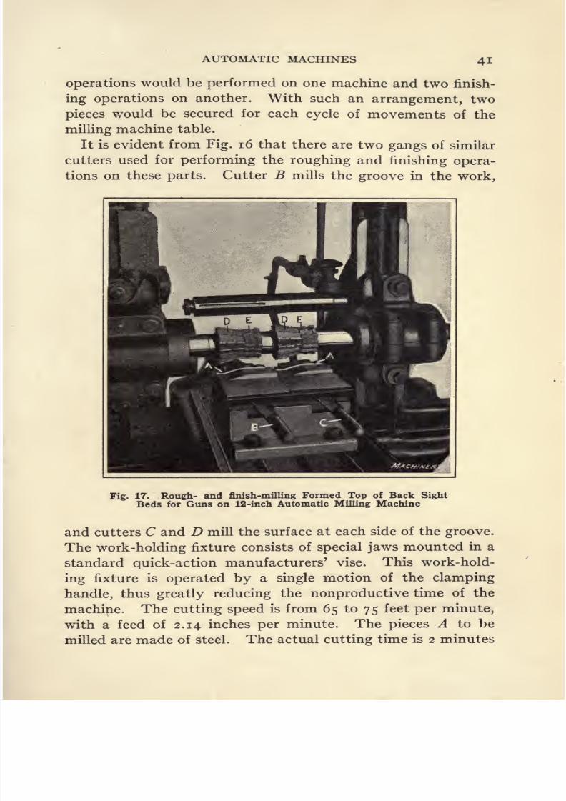
It is evident from Fig. 16 that there are two gangs of similar
cutters used for performing the roughing and finishing opera-
tions on these parts. Cutter B mills the groove in the work,
Fig. 17. Rough- and finish-milling Formed Top of Back Sight
Beds for Guns on 12-inch Automatic Milling Machine
and cutters C and D mill the surface at each side of the groove.
The work-holding fixture consists of special jaws mounted in a
standard quick-action manufacturers' vise. This work-hold-
ing fixture is operated by a single motion of the clamping
handle, thus greatly reducing the nonproductive time of the
machine. The cutting speed is from 65 to 75 feet per minute,
with a feed of 2.14 inches per minute. The pieces A to be
milled are made of steel. The actual cutting time is 2 minutes

8/13/2019 Production Milling
http://slidepdf.com/reader/full/production-milling 56/296
PRODUCTION MILLING
10 seconds per operation, and the loading and unloading time
is 37 seconds, making the total operating period 2 minutes
47 seconds. One operator is able to take care of a group of
three machines working on this job.
Rough- and Finish-milling Work to Desired Contour.
Figure 17 illustrates one of the 12-inch automatic millers set up
to rough- and finish-mill the top of back sight beds for guns,
Fig. 18. Twelve-inch Automatic Milling Machine milling Top,
Bottom, and Ends of Back Sight Leaf
and shows clearly the cutters, work-holding fixture, and the
form to which parts A have to be milled. As in the case of
the rough- and finish-milling operation which has just been
described, the roughing cut on the present job is taken with
the work held in the left-hand fixture; and after this pre-
liminary operation has been performed, the work is reset in
the right-hand fixture ready for the finish-milling operation.
At the time each piece is finished-milled at the right-hand

8/13/2019 Production Milling
http://slidepdf.com/reader/full/production-milling 57/296
AUTOMATIC MACHINES 43
side of the table, another piece is rough-milled at the left-
hand side, so that one piece is finished for each cycle of table
movements. The work-holding fixture consists of special
jaws applied to a standard milling vise; and to clamp or re-
lease the work at either side of the table, it is merely necessary
to give a single movement to lever B or C.
To provide for obtaining the desired contour, two gangs of
milling cutters are mounted on the arbor, each gang consisting
of two cutters D and E. It will be seen that cutters D are
Fig. 19. Five-inch Automatic Milling Machine facing Ends and
milling Groove in Back Sight Leaf Slide
angular mills which provide for finishing the inclined face
of the work, while cutters E are formed to produce the desired
contour at the right-hand end of each piece. On this job,
the cutting speed is 73 feet per minute, and the feed is 1.86
inches per minute. The actual cutting time per piece is i
minute 1 1 seconds, and the loading time is 40 seconds, making
the total time per operation i minute 51 seconds.

8/13/2019 Production Milling
http://slidepdf.com/reader/full/production-milling 58/296
44 PRODUCTION MILLING
Machine Equipped for Milling Top, Bottom, and Ends of
Work. In producing the back sight leaf for a certain type
of gun, it is required to finish the top, bottom, and both ends
of the work. Figure 18 shows a 1 2-inch Pratt & Whitney
automatic miller which is equipped for performing all of these
operations. At the left-hand side of the machine there is a
fixture in which the work is held to allow the top and both
ends of the work to be milled; and after this cut has been
completed, the piece is transferred to the fixture at the right-
hand side of the milling machine table, in which it is heldwhile the bottom of the work is being milled. The fixtures
consist of standard vises equipped with special jaws; and
each of the two vises can be tightened or loosened by manip-
ulating a single handle. These gun sight leaves are ma-
chined from bar stock ff inch by \ inch in cross-sectional
area by 3 inches in length.
A gang of three cutters, C, and D performs the first opera-
tion. The angular mill B finishes the inclined left-hand end
of the work, and the plain mill C faces off the top, while the
narrow side milling cutter D finishes the right-hand end of
the work. Cutter Ej which performs the second operation,
is not fully shown in Fig. 18. From this illustration the im-
pression would be gained that this is a plain mill, but at its
right-hand end, this cutter has an angular face which provides
for milling the inclined shoulder at the right-hand end of the
work. The cutting speed is from 80 to 95 feet per minute,
with a feed of 1.22 inches per minute. The actual machining
time is i minute 58 seconds, and the loading and unloading
time is 43 seconds, making the total production time per
operation 2 minutes 41 seconds. On this job, the operator
looks after a group of two machines.
Milling Ends of Work and Groove in Top Face. To pro-
vide for simultaneously milling both ends and a groove in the
top face of a gun part known as the back sight leaf slide,
a 5-inch automatic milling machine is used, which is equipped
as shown in Fig. 19. The piece A to be milled is made from
bar stock f by T9 inch in cross-sectional area by ij inches in

8/13/2019 Production Milling
http://slidepdf.com/reader/full/production-milling 59/296
AUTOMATIC MACHINES 45
length. In this case, the work-holding fixture provides for
setting up only one piece for the milling operation. This
fixture has a pair of special jaws mounted in a single quick-
action vise of standard design. The arrangement of milling
cutters is quite simple. It consists of a gang of three side
mills, cutter B being utilized for producing the shallow groove
in the work, while cutters C and D face off the ends. On
Fig. 20. Five-inch Automatic Milling Machine milling Top, Side,and End of Back Sight Leaf Slide Dog
this job, the cutting speed is from 80 to 105 feet per minute
with a feed of 1.18 inches per minute. The machining time
per cut is i minute 39 seconds, and the loading time is 27
seconds, making the total time per operation 2 minutes 6
seconds. One operator handles three machines working on
this job.
Milling Top, Side, and End of Work. Figure 20 shows
another 5-inch size of automatic milling machine equipped
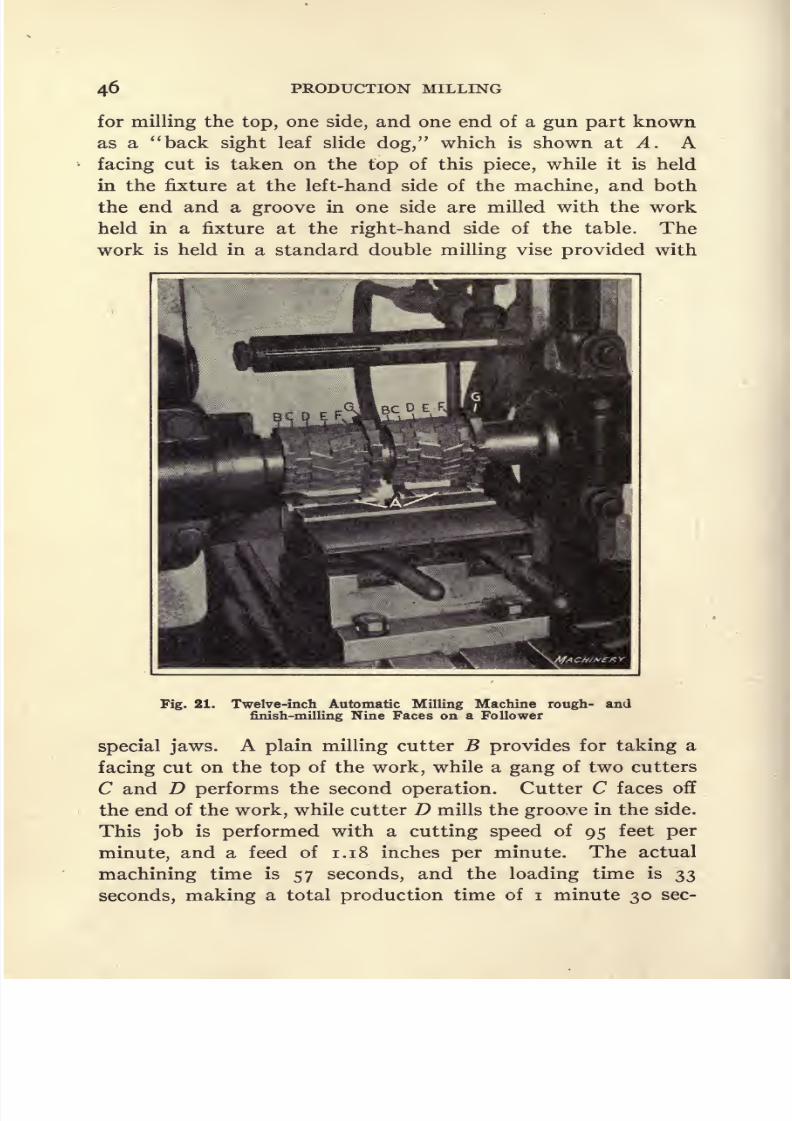
8/13/2019 Production Milling
http://slidepdf.com/reader/full/production-milling 60/296
PRODUCTION MILLING
for milling the top, one side, and one end of a gun part known
as a back sight leaf slide dog, which is shown at A. A
facing cut is taken on the top of this piece, while it is held
in the fixture at the left-hand side of the machine, and both
the end and a groove in one side are milled with the work
held in a fixture at the right-hand side of the table. The
work is held in a standard double milling vise provided with
Fig. 21. Twelve-inch Automatic Milling Machine rough- and
finish-milling Nine Faces on a Follower
special jaws. A plain milling cutter B provides for taking a
facing cut on the top of the work, while a gang of two cutters
C and D performs the second operation. Cutter C faces off
the end of the work, while cutter D mills the groove in the side.
This job is performed with a cutting speed of 95 feet per
minute, and a feed of 1.18 inches per minute. The actual
machining time is 57 seconds, and the loading time is 33
seconds, making a total production time of i minute 30 sec-
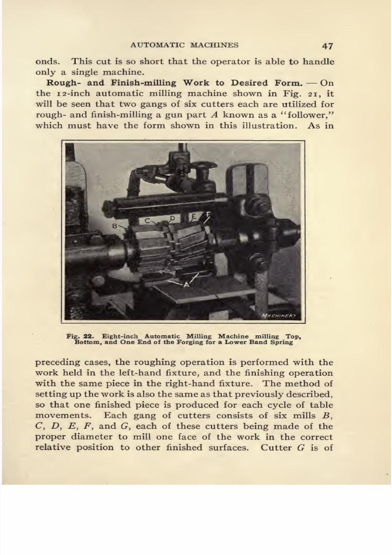
8/13/2019 Production Milling
http://slidepdf.com/reader/full/production-milling 61/296
AUTOMATIC MACHINES 47
onds. This cut is so short that the operator is able to handle
only
asingle
machine.
Rough- and Finish-milling Work to Desired Form. On
the i2-inch automatic milling machine shown in Fig. 21, it
will be seen that two gangs of six cutters each are utilized for
rough- and finish-milling a gun part A known as a follower,
which must have the form shown in this illustration. As in
Fig. 22. Eight-inch Automatic Milling Machine milling Top,
Bottom, and One End of the Forging for a Lower Band Spring
preceding cases, the roughing operation is performed with the
work held in the left-hand fixture, and the finishing operation
with the same piece in the right-hand fixture. The method of
setting up the work is also the same as that previously described,
so that one finished piece is produced for each cycle of table
movements. Each gang of cutters consists of six mills B,
C, D, E, F, and G, each of these cutters being made of the
proper diameter to mill one face of the work in the correct
relative position to other finished surfaces. Cutter G is of

8/13/2019 Production Milling
http://slidepdf.com/reader/full/production-milling 62/296
48 PRODUCTION MILLING
sufficient size so that it overhangs the end of the work and
providesfor
millingit at the same time that the five
topfaces of the piece are machined. These followers are made
from steel bar stock -$ by f inch in cross-sectional area by 3^
inches in length. The cutting speed is from 69 to 89 feet per
minute with a feed of 1.86 inches per minute. On this job,
the actual machining time is i minute 51 seconds, and the
loading time is i minute 8 seconds, making the total produc-
tion time per operation 2 minutes 59 seconds. One operator
is able to handle two machines working on this job.
Milling Top and Bottom Faces and One End of a Forging.
The part shown set up on an 8-inch automatic milling machine
in Fig. 22 is a lower band spring for a gun. This part is made
from a forging, and it is required to mill the top and bottom
faces and one end of the work. The bottom face of work A
must be machined to an irregular contour, and to obtain this
result, a gang of three cutters B, C, and D is used. Cutter
B is formed to correspond with the irregular contour of the
curved section, while cutters C and D provide for milling the
square shoulder and the end of the work, respectively. After
this cut has been completed, the work is placed in the right-
hand fixture and two cutters E and F are utilized for facing
off the flat surface of the work and for straddle-milling the
wall at the right-hand end. The cutting speed on this job is
from 73 to 85 feet per minute, with a feed of 1.86 inches per
minute. The actual machining time per operation is i minute
24 seconds, and the unloading and loading time is 53 seconds,
giving a total production time per operation of 2 minutes 17
seconds. Sufficient time is allowed by the cut to enable one
man to operate two machines working on this job.
Milling a Slot with Non-parallel Sides. An interesting
operation is shown in Fig. 23, which consists of milling the
non-parallel sides and bottom of a slot in the end of a bayonet,
to receive the locking bolt. Two pieces of work A are set up
in the fixture, one behind the other, in such relative positions
that one side and part of the bottom of the slot are milled in
the first piece; and when the second piece is carried up to the

8/13/2019 Production Milling
http://slidepdf.com/reader/full/production-milling 63/296
AUTOMATIC MACHINES 49
cutter, the opposite side and remainder of the bottom of the
slot are milled. Two plain cutters B and C are used in order
that the spiral angles of the teeth may be opposed to each
other to neutralize the end thrust; otherwise, a single cutter
could just as well be employed. After each traverse of the
table, the partially milled piece is removed from the first
station of the fixture and reset in the second position. A fresh
Fig. 23. Eight-inch Automatic Milling Machine milling the
Non-parallel Sides and Bottom of the Lock Groove in
a Bayonet v
blank is then set up in the first station. With this arrange-
ment one piece is completely milled at each cycle of move-
ments of the milling machine table.
Design of Work-holding Fixture Used. The construction
of the fixture used for performing this operation is shown in
Fig. 24. It has a clamping mechanism that is operated with
a single cam-lever A, the cam being attached to a sliding
member B, and acting against a sliding block C. This results
in drawing back the sliding member B and pushing forward
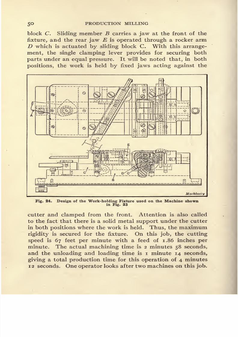
8/13/2019 Production Milling
http://slidepdf.com/reader/full/production-milling 64/296
PRODUCTION MILLING
block C. Sliding member B carries a jaw at the front of the
fixture, and the rear jaw E is operated through a rocker arm
D which is actuated by sliding block C. With this arrange-
ment, the single clamping lever provides for securing both
parts under an equal pressure. It will be noted that, in both
positions, the work is held by fixed jaws acting against the
Machinery
Fig. 24. Design of the Work-holding Fixture used on the Machine shownin Fig. 23
cutter and clamped from the front. Attention is also called
to the fact that there is a solid metal support under the cutter
in both positions where the work is held. Thus, the maximum
rigidity is secured for the fixture. On this job, the cutting
speed is 67 feet per minute with a feed of 1.86 inches per
minute. The actual machining time is 2 minutes 58 seconds,
and the unloading and loading time is i minute 14 seconds,
giving a total production time for this operation of 4 minutes
12 seconds. One operator looks after two machines on this job.
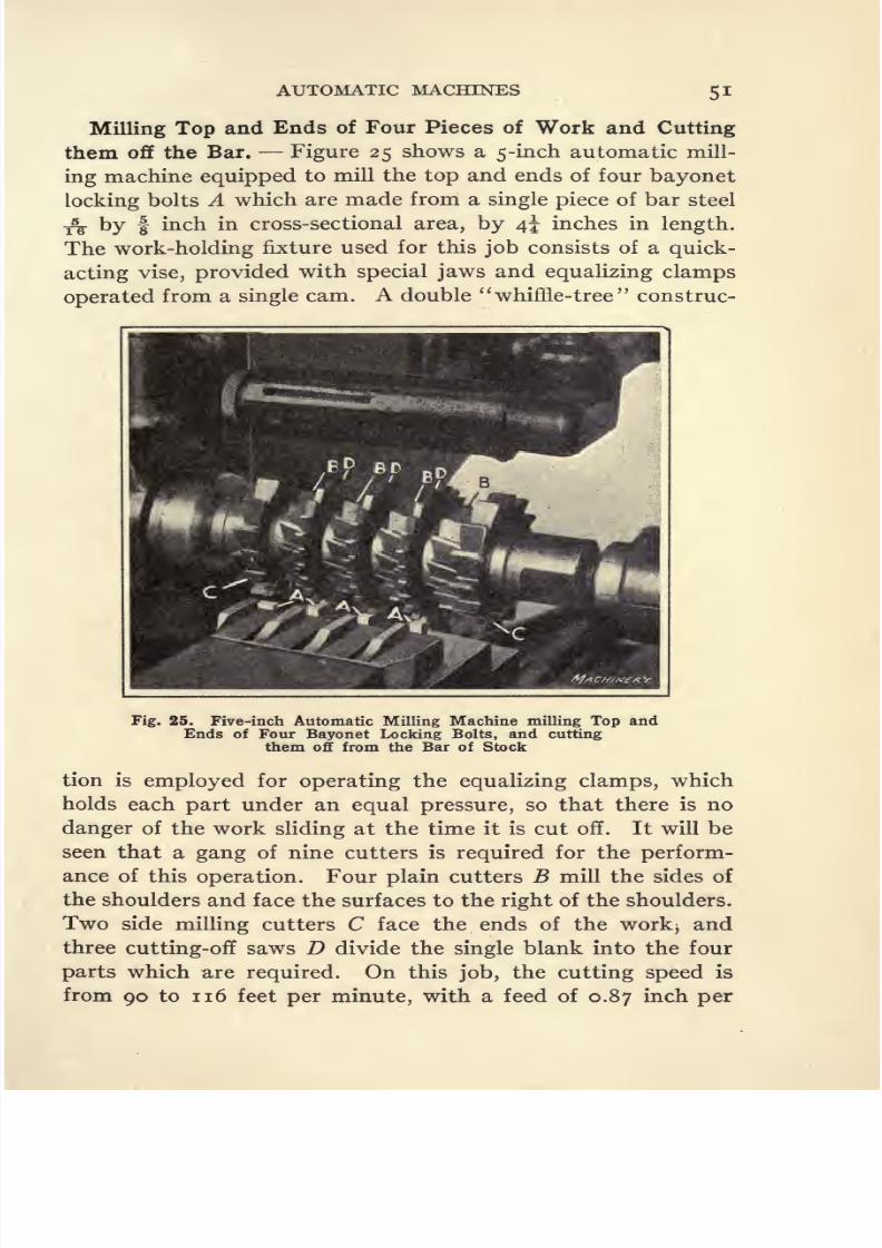
8/13/2019 Production Milling
http://slidepdf.com/reader/full/production-milling 65/296
AUTOMATIC MACHINES 51
Milling Top and Ends of Four Pieces of Work and Cutting
them off the Bar. Figure 25 shows a 5-inch automatic mill-
ing machine equipped to mill the top and ends of four bayonet
locking bolts A which are made from a single piece of bar steel
^ by f inch in cross-sectional area, by 4^ inches in length.
The work-holding fixture used for this job consists of a quick-
acting vise, provided with special jaws and equalizing clamps
operated from a single cam. A double whiffle-tree construc-
Fig. 25. Five-inch Automatic Milling Machine milling Top andEnds of Four Bayonet Locking Bolts, and cutting
them off from the Bar of Stock
tion is employed for operating the equalizing clamps, which
holds each part under an equal pressure, so that there is no
danger of the work sliding at the time it is cut off. It will be
seen that a gang of nine cutters is required for the perform-
ance of this operation. Four plain cutters B mill the sides of
the shoulders and face the surfaces to the right of the shoulders.
Two side milling cutters C face the ends of the work> and
three cutting-off saws D divide the single blank into the four
parts which are required. On this job, the cutting speed is
from 90 to 116 feet per minute, with a feed of 0.87 inch per
8/13/2019 Production Milling
http://slidepdf.com/reader/full/production-milling 66/296
52 PRODUCTION MILLING
minute. The actual cutting time is 2 minutes i second, and
the unloading and loading time is 36 seconds, making the total
time per operation 2 minutes 37 seconds. One operator is
able to attend to two machines working on this job. Ohio
Tilted Rotary Milling Machine. In the Ohio
tilted rotary milling machine, built by the Oesterlein Machine
Co., provision has been made to enable it to be operated on
either the continuous rotary or the indexing principle. When
used as an indexing machine, two or more working-holding
fixtures are mounted at the periphery of the circular table of
the Ohio miller, and a suitably arranged mechanism pro-
vides for alternately indexing the table to bring the next
piece of work into the operating position, and then feeding
the cutter-head in toward the center of the table, so that the
cutters are fed across the work. Such an arrangement enables
a high rate of production to be obtained, because a number
ofpieces
of workmay
be mounted around theperiphery
of
the table, and the table may be indexed at high speed to bring
the successive castings or forgings into the milling position.
The cutter-head is also withdrawn from the work at high
speed, the slow-feed movement being utilized only during
the actual cutting. The operator of this machine is only
required to remove the finished pieces of work from the fixtures
and set up fresh blanks, so that there is virtually no idle time
of either the machine or its operator.
Milling Yoke Forgings. Figure 26 shows a machine
equipped with two work-holding fixtures arranged for opera-
tion on the indexing principle. This machine is used at the
plant of the Stuebing Truck Co., for straddle-milling the out-
side faces of cast-steel yokes. The advantage secured by the
indexing principle of operation is quite apparent in this case,
because if the machine were used as a continuous rotary miller,
a great deal of time would be lost in moving the table through
practically a complete semicircle between each of the milling
cuts. As the cuts are quite short, the percentage of idle time
would be very high, especially in view of the fact that a low
rate of feed must be used in milling these steel castings. The

8/13/2019 Production Milling
http://slidepdf.com/reader/full/production-milling 67/296
AUTOMATIC MACHINES 53
illustration shows the machine just as it is about to commence
the straddle-milling operation. The spindle head carrying
the straddle-mills will feed radially toward the center of the
table until the cut is completed, after which a dog will auto-
matically trip the feed movement and engage a rapid return
mechanism which will carry the cutters quickly out of engage-
ment with the work. At the same time, the table indexing
Fig. 26. Straddle-milling Yoke Forgings on Tilted Rotary Milling Machine
operated on Indexing Principle
mechanism will be automatically engaged, causing the table
to be quickly moved through a half revolution, ready for
milling the next casting which has been set up in the fixture
at the opposite side of the table. While this piece is being
milled, the operator will remove the finished piece and sub-
stitute a fresh blank in its place.
Work-holding Fixtures for Milling Yoke Forgings. On
this job, it is of great importance to provide work-holding fix-
8/13/2019 Production Milling
http://slidepdf.com/reader/full/production-milling 68/296
54 PRODUCTION MILLING
tures with a quick-acting clamping mechanism, because the
time required to take the cut on these forgings is quite short,
so that the operator has only a limited period in which to
remove the milled yoke, and to set up a rough forging in its
place. For this purpose, it is merely necessary for the operator
to turn nut A through about half a revolution, after which
the bolt may be swung on pivot B to enable strap C to be
raised. On the under side, it will be seen that this strap carries
a V-block D that fits over the top of the forging; and on its
under side, the forging is supported by a similar V-block E.
Endwise location of the work is provided by a pilot F, which
fits through a hole tjiat has previously been drilled in the inner
end of each forging. After the milled piece has been removed
from the fixture, the operator sets up a new forging by merely
slipping it over pilot F and then dropping strap C into place
on top of the forging. The clamping bolt is next swung up
into the slotted end of strap C, after which nut A is tightened.
Very little time is required for unloading and reloading the
fixture. On this operation, the time taken in milling one
forging is forty seconds; that is to say, the rate of production
is ninety forgings per hour.
Straddle-milling and Slitting Pinion Flanges. The Ohio
tilted rotary miller as described, has been designed in such a
waythat the table
mayeither be rotated
continuously
to
pro-vide for feeding work to the cutters, or so that the indexing
principle may be utilized, whereby the table brings a piece of
work into position opposite the cutters and then stops while
the ram, by which the cutter-spindle is carried, moves forward
to feed the cutters radially across the work.
Fixture for Straddle-milling and Slitting Pinion Flanges.
Figure 27 shows a close-up view of the table, cutters and work-
holding fixture of an Ohio tilted rotary miller which has
been equipped for milling pinion flanges, utilizing the index-
ing principle. Obviously this is necessary because only two
pieces of work are set up on the table at a time and because
the cutter must be fed into and not over or through the
work, as is essential in continuous milling. Referring

8/13/2019 Production Milling
http://slidepdf.com/reader/full/production-milling 69/296
AUTOMATIC MACHINES 55
first to the work shown at the left-hand side of this illustra-
tion, attention is called to the fact that the operation to be
performed consists of straddle-milling the ends A of a boss
on the work, and of cutting a slit at the center. By compar-
ing the arrangement of the milling cutters and slitting saw
with the form of the work, the nature of this operation will
at once become apparent. Air-operated work-holding fixtures
are employed, these fixtures being tightened by throwing lever
Fig. 27. Two -station Air-operated Fixture for straddle-milling and slitting
Pinion Flanges
B in one direction while the work is released from the fixture
by an opposite movement of the valve lever. After a milling
operation has been completed the table indexes through 180
degrees to provide for bringing a casting which has already
been set up in the second fixture, into the operating position,
while the other fixture is carried around to the loading posi-
tion so that the operator may remove the milled pinion flange
and set up a fresh casting in its place.
At the time the work comes to this machine it has been
bored and the flange has been turned and faced, so that these4M

8/13/2019 Production Milling
http://slidepdf.com/reader/full/production-milling 70/296
56 PRODUCTION MILLING
surfaces may be utilized as locating points. Arbor C enters
the bore of the pinion flange and the face of the flange goes
back against the finished vertical surface of the fixture. With
the work located in this way, valve lever B is thrown over to
admit air to cylinder D, so that the piston in this cylinder will
rise and rock latch E on its pivotal support to enable this
latch to drop over the flange on the work, and hold it back in
place on the fixture. It will be apparent that with a casting
Fig. 28. Work-holding Fixture of Similar Design to that shown in Fig. 27,
except that there are Four Stations, with Two Pieces of Workmounted at Each Station
in the operating position, the ram by which the cutter-spindle
is carried moves forward to provide for feeding the milling
cutters across the ends A of the boss to be milled on the work
and dropping the slitting saw into the middle of the boss.
On this job the rate of production is 120 pieces in one hour.
Straddle-milling a Boss and Making a Saw-cut in Pinion
Flanges. Figure 28 shows a job which is quite similar to
the one described in connection with the previous illustration.
The operation consists of straddle-milling a boss, and dropping
a saw-cut into automobile pinion flanges; but as this machine
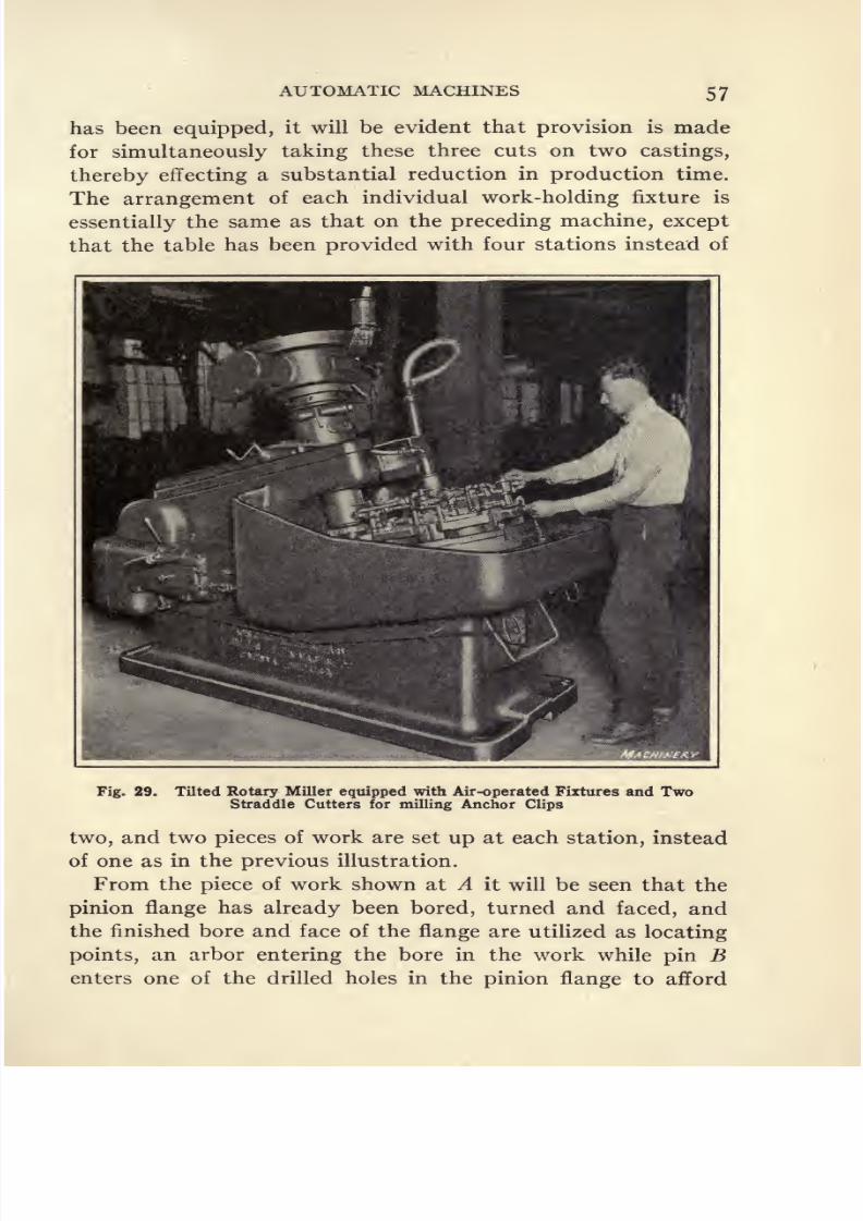
8/13/2019 Production Milling
http://slidepdf.com/reader/full/production-milling 71/296
AUTOMATIC MACHINES 57
has been equipped, it will be evident that provision is made
for simultaneously taking these three cuts on two castings,
thereby effecting a substantial reduction in production time.
The arrangement of each individual work-holding fixture is
essentially the same as that on the preceding machine, except
that the table has been provided with four stations instead of
Fig. 29. Tilted Rotary Miller equipped with Air-operated Fixtures and TwoStraddle Cutters for milling Anchor Clips
two, and two pieces of work are set up at each station, instead
of one as in the previous illustration.
From the piece of work shown at A it will be seen that the
pinion flange has already been bored, turned and faced, and
the finished bore and face of the flange are utilized as locating
points, an arbor entering the bore in the work while pin Benters one of the drilled holes in the pinion flange to afford

8/13/2019 Production Milling
http://slidepdf.com/reader/full/production-milling 72/296
5 PRODUCTION MILLING
the desired location. As each station comes into operating
position, the ram feeds the cutters and slitting saw radially
inward toward the center of the table, so that the two milling
cutters can straddle-mill a boss on each of the castings be-
tween which they are fed, while the saw carried between the
cutters provides for slitting each of the castings. On this job
the rate of production is 240 pieces per hour. On account of
the automatic operation of the machine, it acts as a pace-
Fig. 30. Close-up View of Work, Fixtures and Cutters on the MillingMachine illustrated in Fig. 29
maker for the operator so that a steady rate of output is
secured.
Straddle-milling Anchor Clips. Figures 29 and 30 show an
Ohio tilted rotary miller equipped with fixtures for a
straddle-milling operation on anchor clips. It will be apparent
that pneumatic fixtures are used for holding the work and
Fig. 29 shows the operator manipulating the air valve with
his right hand while he holds one of the anchor clips in his
left hand. From the close-up view of the table, cutters and

8/13/2019 Production Milling
http://slidepdf.com/reader/full/production-milling 73/296
AUTOMATIC MACHINES 59
work-holding fixtures illustrated in Fig. 30, a better idea will
be obtained of the tooling of this miller. In this illustration
attention is first called to the fact that it is the surfaces A at
opposite sides of the work which have to be straddle-milled.
Nine fixtures are distributed around the circumference of the
rotary table. To provide for clamping or releasing the air-
Fig. 31. Fixture for Continuous Milling of Universal Joint Forgings
operated fixture at each station of the table, it is merely neces-
sary for the operator to throw valve lever B in one direction
to secure the work, or to move this lever in the opposite direc-
tion to release the grip upon a piece which has been milled.
It will be seen that there is an air cylinder C located behind
each of the work-holding fixtures, and that the frame D of
,the fixture is made of sufficient width so that when a piece of
work is clamped in place, surfaces A will project above and

8/13/2019 Production Milling
http://slidepdf.com/reader/full/production-milling 74/296
60 PRODUCTION MILLING
below the top and bottom of frame D so that they can be
reached by the straddle-milling cutters.
A fairly accurate location is accomplished by V-block Ethat receives the cylindrical boss on the work, and when
valve B is opened to admit air to the cylinder, two sliding
clamps F are pushed forward to hold the work securely in
place against a pad, the contour of which conforms to the
work. A fixture of this kind can be loaded and unloaded with
great rapidity. The automatic station principle of milling is
employed, so that thetable is
constantly indexing piecesof
work to the cutting position, and the operator is able to devote
all of his time to setting up blanks and removing milled pieces
of work. For this reason and also because of the fact that the
fixture has been designed to facilitate loading and unloading,
the rate of production obtained is 240 anchor clips per hour.
Milling Universal Joint Forgings. An example of con-
tinuous milling on an Ohio tilted rotary milling machine is
illustrated in Fig. 31 which shows the fixture developed for
straddle- milling universal joint forgings. It will be ap-
parent that the fixture is divided into twenty-two stations
so that a practically continuous ring of forgings is carried,
thus reducing the percentage of time lost while the table is
traversing between successive pieces of work. Referring to
the piece of work, it will be seen that shank A has been turned
and this shank is used as the locating point, a bushing of the
proper size to receive the shank of the work being provided
on each station of the fixture. The operation to be performed
consists of milling the faces of the yoke, and a suitable gang
of cutters, is provided in order to finish these faces simultane-
ously.
Bearing in mind the fact that this fixture rotates in a clock-
wise direction, it will be evident that lugs or brackets B,which are provided at each station, come into contact with
the back side of the yoke and prevent any tendency for it to
twist out of position. Of course, it will be apparent that lugs
B are made thinner than each horn of the yoke, so that the
brackets do not interfere with the operation of the milling

8/13/2019 Production Milling
http://slidepdf.com/reader/full/production-milling 75/296
AUTOMATIC MACHINES 6l
cutters. A screw-operated clamping mechanism secures the
work in this fixture, and it is merely necessary for the operator
to use the T-head wrench to release each milled piece of work,
and tighten a fresh forging in its place. On this job, where
the finish must be exceptionally good, the rate of production
obtained is 90 pieces per hour.
Cross-slotting Bevel Gear Blanks. At the plant of the
Goodell-Pratt Co., Greenfield, Mass., an automatic milling ma-
Fig. 32. Slotting Small Bevel Gear Blanks
chine built by the Bilton Machine Tool Co. is used in milling
two slots at 90 degrees to each other across the hub of small
bevel gear blanks. Figure 32 shows a close view of the fixture
and cutters that are provided on the machine used for this
purpose. It will be seen that this miller has two spindles
mounted in such relative positions that the cutters are located
at a quarter of a revolution of the work-holding table from
each other. The table revolves intermittently and the work-
holding fixture is of very simple design, consisting merely of

8/13/2019 Production Milling
http://slidepdf.com/reader/full/production-milling 76/296
62 PRODUCTION MILLING
pilots to enter the drilled and reamed hole in each bevel gear
blank, and a spring clip at the side of each pilot to provide
sufficient frictional resistance to keep the work down in place
on the fixture. It is evident that very little power is required
for this purpose because the cutters are fed down on the
work.
Sequence of Operations in Cross-slotting Bevel Gear Blanks.
On this job, the cycle of operations is as follows: The
operator stands beside the machine, and in the position where
one pilot is shown with a blank lying beside it, he lifts the
milled piece of work off the pilot and substitutes a fresh blank
in its place. Movement of the table is intermittent, a suffi-
cient dwell being allowed while the blanks are under the two
cutters so that these cutters can feed down to mill slots in the
work. These two synchronized movements of the cutter-heads
and work-holding table are obtained from a camshaft at the
back of the machine, the cutter-head being mounted on a
vertical slide and the work-holding table provided with a
ratchet and pawl mechanism to give the desired results. A
fresh blank has the first slot cut in it when it reaches the first
cutter, and after the table has carried this blank around
through an interval of 90 degrees, the second slot is cut while
the work is under the other milling cutter. One completely
slotted blank is thus obtained for each index-movement of the
table, or one travel of the cutter-head.
On this job the slots to be milled are | inch by f inch, and
the hole through the work is ^f inch in diameter, while the
diameter of the boss in which the slots are milled is inch.
The milling cutters are 3 inches in diameter, and they are
driven at a speed of 202 revolutions per minute, which
corresponds to a cutting speed of 158^ feet per minute. The
rate of production obtained is 6000 completely milled parts
in a ten-hour working day.
Operations on Potter & Johnston Indexing Milling Ma-
chines. Before describing the methods of handling those
milling operations for which the indexing type of machine
built by the Potter & Johnston Machine Co. is adapted, it

8/13/2019 Production Milling
http://slidepdf.com/reader/full/production-milling 77/296
AUTOMATIC MACHINES
will be well to study the features of this miller. From Fig.
33 it will be seen that two parallel work-holding tables are
provided, which are mounted at a fixed height from the floor
on a circular indexing turntable that provides for bringing the
two work-holding tables alternately into the operating and
Fig. 33. Automatic Indexing Type of Milling Machine
loading positions.The
operatorloads the work in the fixtures
mounted on one table while the cutters are working on pieces
held in fixtures on the other table, so that both the machine
and the operator are kept constantly employed, except for the
brief intervals during which the machine is indexing. The
finished work is not moved back under the milling cutters,
hence there is no danger of marring the finish of the work in

8/13/2019 Production Milling
http://slidepdf.com/reader/full/production-milling 78/296
64 PRODUCTION MILLING
g
Uti
T
ao
Is,
0)
1
I

8/13/2019 Production Milling
http://slidepdf.com/reader/full/production-milling 79/296
AUTOMATIC MACHINES 65
making such a return movement of the table. By mounting
the spindle on a slide carried by the column, provision is made
for obtaining vertical adjustment of the position of the spindle;
and the column is carried by a horizontal slide which affords
transverse adjustment for the spindle, so that any desired
position on the table can easily be reached.
Milling a Turret Revolving Pawl. Figure 34 shows two
views of the finished turret revolving pawl after being milled,
and also diagrams indicating the manner in which successive
milling operations are performed in making this part. Thereare nine operations required for the production of each of
these pawls. The first eight are milling operations, and these
will be discussed in detail; but as the final operation consists
of drilling and counterboring a hole in the pawl, no considera-
tion will be given to this part of the work. The machine steel
from which these pawls are made is delivered to the milling
departmentin blocks
measuring 10^inches
long by2
incheshigh by i^ inches thick. Each of these pieces of steel contains
sufficient material for making two pawls, a piece 5 inches in
length being required for each pawl, while ^ inch is allowed
for the kerf removed by a parting tool. The reader will obtain
the best idea of the way in which the successive operations are
performed on these parts by referring to Fig. 34, which shows
in- diagrammatic form the successive steps that are involved.
Operation i consists of squaring up the four sides of each
steel blank, so that they are at accurate right angles to each
other. After this has been done, the second operation is to
part the blanks at the center, in order to produce two pieces,
each of which is 5 inches in length.
Methods of Tooling up for Milling Operations on Turret
Revolving Pawls. Some of the methods employed in tool-
ing up for the milling operations on these pawls are quite
unusual. A case in point is seen in the provision made for
performing Operations 3 and 4, as indicated in the diagrams
shown in Fig. 34. The machine used for the performance of
both of these operations is illustrated in Fig. 35, where it
will be noticed that provision is made on a single machine for

8/13/2019 Production Milling
http://slidepdf.com/reader/full/production-milling 80/296
66 PRODUCTION MILLING
simultaneously performing two operations. Two concave or
formed milling cutters are used to finish the upper and lower
edges of the blanks to a radius of J inch and 4 inches, respec-
tively.
The fixture mounted on each of the work-holding tables
provides for holding two rows of five pieces each, so that at
every traverse of the table ten pieces are milled, five on the
upper end and five on the lower end. Then the turntable is
Fig. 35. Indexing Milling Machine equipped for performing Third
and Fourth Operations on Turret Revolving Pawls
indexed to bring the fixture carrying these milled pieces around
to the loading position. Five of these pieces are milled at both
the
top
and bottom, while the other five are milled
only
at
the top. As a result, five finished pieces are removed from
the fixture, and the other five, which have been milled only
at the top, are taken out of that side of the fixture in which
they were held for the third operation, turned over end for
end, and replaced in the opposite side of the fixture, on the
same table, ready for performing the fourth operation. Then

8/13/2019 Production Milling
http://slidepdf.com/reader/full/production-milling 81/296
AUTOMATIC MACHINES
five other pieces are set up in the other side of the fixture
ready to have the third operation performed on them. After
milling operations have been performed on the pieces carried
by the fixture mounted on the other work-holding table, the
machine will be indexed to provide for milling the pieces that
have just been set up.
The fixtures for holding the work for milling are of quite
simple design. It will be recalled that the blanks have already
Fig. 36. Indexing Milling Machine equipped for performing Fifth
and Sixth Operations on Turret Revolving Pawls
been faced off on all four sides, and in setting them up for
the third and fourthoperations,
five blanks are secured in
each side of the work-holding fixture. By tightening set-
screws A,these pieces of work are pushed back against blocks
B, which support the thrust of the milling cutters. Then as
an additional means of steadying the work and holding it
down in the fixture, five set-screws C provided at each side
are tightened against the work.

8/13/2019 Production Milling
http://slidepdf.com/reader/full/production-milling 82/296

8/13/2019 Production Milling
http://slidepdf.com/reader/full/production-milling 83/296
AUTOMATIC MACHINES 69
work at different angles for handling the two operations. On
the work-holding table shown at the right-hand side of the
machine in Fig. 36, it will be seen that the fixture provides for
holding the pieces at right angles to the direction of travel of
this table, so that a straight slot is milled across the work, as
indicated diagrammatically for the fifth operation in Fig. 34.
At the left-hand side of the machine, a similar form of work-
holding fixture is provided, except that this fixture holds the
pieces inclined at an angle of 40 degrees to the direction of
travel of the table. The pieces milled while held in the fixture
mounted on the right-hand table are taken out when this
table is indexed to the loading position, and they are then set
in the fixture on the other work-holding table, ready for the
performance of the sixth operation, as indicated in Fig. 34.
It will be apparent from Fig. 36 that the work-holding fix-
tures provided at both sides of the machine are of simple
design. They have thrust blocks A, which serve the double
purpose of supporting the work against the pressure of the
milling cutter, and also locating the pieces to be milled at the
proper angle to the direction in which the table travels. The
thrust block will be at right angles to the direction of table
travel for the fifth operation, and inclined at an angle of 40
degrees for the sixth operation. After the pieces of work have
been located against these thrust blocks, they are held downby means of straps B, which are made of sufficient width so
that each strap holds two pieces of work. Four pieces are
held in each fixture, so that the milling operation can be per-
formed on all of them at a single setting of the work.
Milling One Side of Pawl to Slight Taper Angle. Opera-
tion 7 consists of milling one side of the turret revolving pawl
to a slight taper angle, and for the performance of this opera-
tion the milling machine is equipped as shown in Fig. 37. It
will be evident that the fixture carried by the work-holding
table at each side of the machine consists of a milling vise of
standard design, which holds two pieces of work. The only
special feature of each of these vises is that a tapered block is
placed between the jaws, and the work to be milled is laid on

8/13/2019 Production Milling
http://slidepdf.com/reader/full/production-milling 84/296
7 PRODUCTION MILLING
this block before the jaws are tightened. In this way, provision
is made for inclining the sides of the two pieces of work at such
an angle that the regular horizontal movement of the table
results in milling off one side of the work to the desired angle
of taper.
Milling Opposite Side of Pawl to Required Angle. The
eighth and final milling operation performed on these pieces,
consists of milling the opposite edge of the pawl in the manner
Fig. 38. Indexing Milling Machine equipped for performing
Eighth Operation on Turret Revolving Pawls
indicated in Fig. 34. Here it will be seen that the cut to be
taken is ^ inch deep, and that it is taken at an angle to the
parallel edge of the work, thus sharpening the wedge-shaped
form of the highest portion of this side of the pawl. Figure 38
shows the equipment for this operation. It will be seen that
the work-holding fixture mounted on each of the tables is so
designed that provision has been made for mounting six
pieces of work in each fixture. The fixtures on both tables are
of identical design, and it will be apparent that each has two

8/13/2019 Production Milling
http://slidepdf.com/reader/full/production-milling 85/296
AUTOMATIC MACHINES 71
rows of work A mounted in it. Two rows of straps B hold
thesepieces;
and theproper
location of the work is obtained
by means of center blocks C against which the work is clamped,
to obtain the proper inclination with the direction of travel of
the work-holding table.
It will be seen that two inserted-tooth milling cutters are
mounted on the arbor, and these are located in such a way
Fig. 39. Indexing Rotary Milling Machine equipped for squaringHeads of Cap-screws
that a single traverse of the table provides for milling the
two rows of pieces of work on their inner edges. In order to
perform the operation in this way, it will be evident that the
work must be set up in the fixture with the ends of the pieces
in one row facing in the opposite direction to the ends of the
pieces in the other row held by the same fixture. On each
fixture there are a block D and a pin E, which support the
pieces of work at the ends of the two rows, so that the thrust
of the milling cutters will not have a tendency to cause these
pieces to alter their position in the fixture.
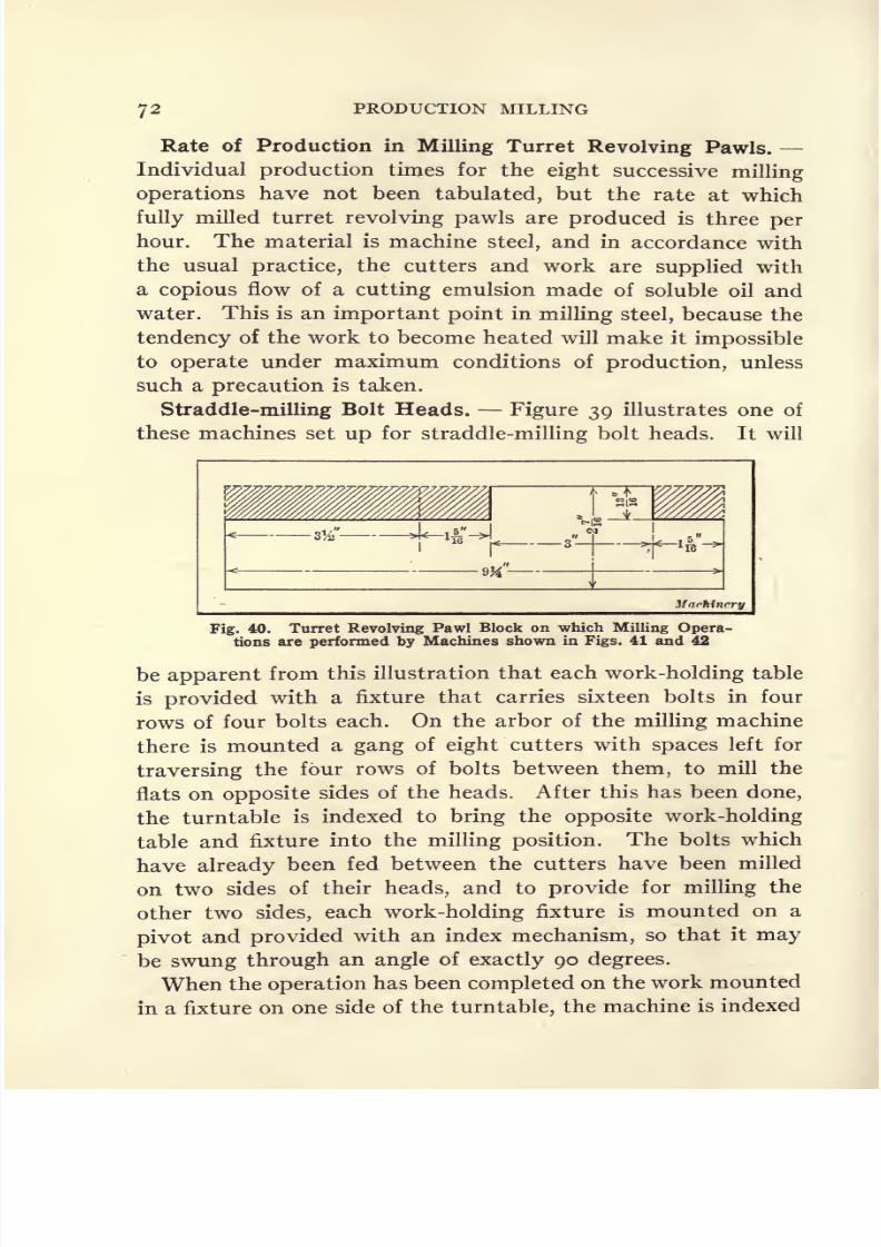
8/13/2019 Production Milling
http://slidepdf.com/reader/full/production-milling 86/296
PRODUCTION MILLING
Rate of Production in Milling Turret Revolving Pawls. -
Individual production times for the eight successive milling
operations have not been tabulated, but the rate at which
fully milled turret revolving pawls are produced is three per
hour. The material is machine steel, and in accordance with
the usual practice, the cutters and work are supplied with
a copious flow of a cutting emulsion made of soluble oil and
water. This is an important point in milling steel, because the
tendencyof the work to become heated will make it
impossibleto operate under maximum conditions of production, unless
such a precaution is taken.
Straddle-milling Bolt Heads. Figure 39 illustrates one of
these machines set up for straddle-milling bolt heads. It will
Fig. 40. Turret Revolving Pawl Block on which Milling Opera-tions are performed by Machines shown in Figs. 41 and 42
be apparent from this illustration that each work-holding table
is provided with a fixture that carries sixteen bolts in four
rows of four bolts each. On the arbor of the milling machine
there is mounted a gang of eight cutters with spaces left for
traversing the four rows of bolts between them, to mill the
flats on opposite sides of the heads. After this has been done,
the turntable is indexed to bring the opposite work-holding
table and fixture into the milling position. The bolts which
have already been fed between the cutters have been milled
on two sides of their heads, and to provide for milling the
other two sides, each work-holding fixture is mounted on a
pivot and provided with an index mechanism, so that it may
be swung through an angle of exactly 90 degrees.
When the operation has been completed on the work mounted
in a fixture on one side of the turntable, the machine is indexed
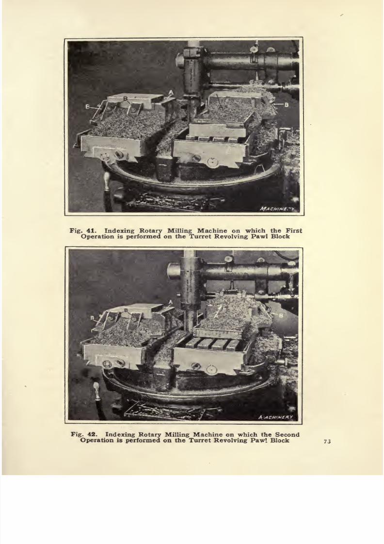
8/13/2019 Production Milling
http://slidepdf.com/reader/full/production-milling 87/296
Fig. 41. Indexing Rotary Milling Machine on which the First
Operation is performed on the Turret Revolving Pawl Block
Fig. 42. Indexing Rotary Milling Machine on which the Second
Operation is performed on the Turret Revolving Pawl Block 7.3
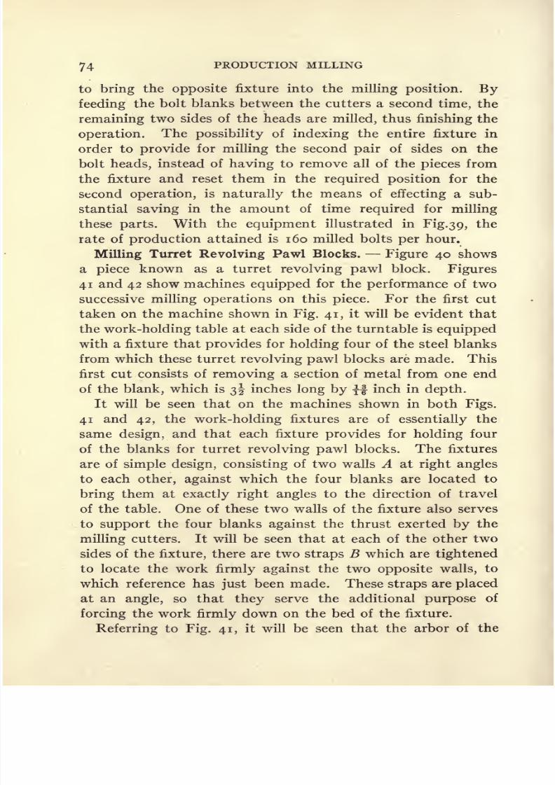
8/13/2019 Production Milling
http://slidepdf.com/reader/full/production-milling 88/296
74 PRODUCTION MILLING
to bring the opposite fixture into the milling position. By
feedingthe bolt blanks between the cutters a second
time,the
remaining two sides of the heads are milled, thus finishing the
operation. The possibility of indexing the entire fixture in
order to provide for milling the second pair of sides on the
bolt heads, instead of having to remove all of the pieces from
the fixture and reset them in the required position for the
second operation, is naturally the means of effecting a sub-
stantial saving in the amount of time required for milling
these parts. With the equipment illustrated in Fig.3 9, the
rate of production attained is 160 milled bolts per hour.
Milling Turret Revolving Pawl Blocks. Figure 40 shows
a piece known as a turret revolving pawl block. Figures
41 and 42 show machines equipped for the performance of two
successive milling operations on this piece. For the first cut
taken on the machine shown in Fig. 41, it will be evident that
the work-holding table at each side of the turntable is equipped
with a fixture that provides for holding four of the steel blanks
from which these turret revolving pawl blocks are made. This
first cut consists of removing a section of metal from one end
of the blank, which is 3 inches long by f inch in depth.
It will be seen that on the machines shown in both Figs.
41 and 42, the work-holding fixtures are of essentially the
same design, and that each fixture provides for holding fourof the blanks for turret revolving pawl blocks. The fixtures
are of simple design, consisting of two walls A at right angles
to each other, against which the four blanks are located to
bring them at exactly right angles to the direction of travel
of the table. One of these two walls of the fixture also serves
to support the four blanks against the thrust exerted by the
milling cutters. It will be seen that at each of the other two
sides of the fixture, there are two straps B which are tightened
to locate the work firmly against the two opposite walls, to
which reference has just been made. These straps are placed
at an angle, so that they serve the additional purpose of
forcing the work firmly down on the bed of the fixture.
Referring to Fig. 41, it will be seen that the arbor of the

8/13/2019 Production Milling
http://slidepdf.com/reader/full/production-milling 89/296
8/13/2019 Production Milling
http://slidepdf.com/reader/full/production-milling 90/296
CHAPTER III
CONTINUOUS ROTARY MILLING
IN shops where there are a large number of duplicate parts
on which one or more surfaces have to be milled, satisfactory
rates of
production
can often be obtained through the use of
so-called continuous rotary milling fixtures. The work-
holding fixture is so named because it rotates continuously to
provide for feeding successive pieces of work under the milling
cutters on the machine. The fixture is constructed to hold a
number of pieces, and is carried on a revolving table. As the
operator is constantly employed removing finished pieces of
work and substituting fresh blanks, a high rate of production
may be obtained by this method. Production may also be
increased in many cases by employing two or more cutters for
straddle-milling. Furthermore, a two-spindle machine maybe used to good advantage for milling opposite ends of the
work. The increased production obtained by continuous
rotary milling is due to reducing the non-productive time of
the machine by avoiding the necessity of stopping to set up
work and then restarting the machine, by avoiding the needof returning the table to the starting point after each traverse,
and by overcoming the necessity of having the machine idle
while the operator is setting up work, or the operator idle
while the machine is running,
Continuous rotary milling is adapted for handling a con-
siderable range of work, as indicated by the illustrations. Gen-
erally,the best results are obtained with continuous
rotarymilling where the pieces to be machined are of rather small
size, so that several parts may be mounted in the fixture at one
time. For machining automobile crankcases, it is probable
that just as satisfactory a rate of production would be obtained
by handling the work on a planer-type milling machine, on
76

8/13/2019 Production Milling
http://slidepdf.com/reader/full/production-milling 91/296
CONTINUOUS ROTARY MILLING 77
which a number of castings could be set up and all of them
milled at a single traverse of the table. For milling small
parts such as the armature cores, however, the continuous
rotary process is the best method.
Importance of Correct Design of Work-holding Fixtures. -
When working out the details of continuous rotary milling
fixtures, regardless of the special nature of the operation re-
quired, the designer should observe certain general principles,
particularlythe
following:
As the rate of
productionis
usuallylimited by the operator's ability to remove finished work and
substitute fresh castings in the fixture, the action of the clamp-
ing devices should be made as simple and rapid as possible.
Also, clamps should be so designed that they will grip the
work securely without producing distortion. Another im-
portant point is to have the pieces of work held as close to
each other as possible, because the table rotates at a uniform
speed, so that the total non-productive time for each complete
revolution of the fixture is represented by the amount of time
wasted while the cutters are passing over gaps between adja-
cent pieces of work. The output is not dependent upon
the number of pieces which the fixture holds, but upon the
rate at which these pieces are fed to the milling cutters.
This rate of production is, of course, independent of the
diameter of the fixture, and generally the circle should be
made as small as is consistent with the shape and size of the
pieces to be milled, as this will reduce the cost of the fixture.
Where there are several parts of the same general design but
slightly different sizes, it is often practicable to design a single
fixture for milling two or more pieces of work, thus substan-
tially reducing the incidental expense for special equipment.
Unless it cannot be avoided, fixtures should never be designed
in a way which will make it impossible for the operator to
remove milled pieces and replace fresh blanks as rapidly as
the table of the machine revolves. Two or more operators can
often be employed to load and unload the fixtures, thus allow-
ing the feed and rate of production obtained to be greatly
increased.
8/13/2019 Production Milling
http://slidepdf.com/reader/full/production-milling 92/296
78 PRODUCTION MILLING
In designing a fixture to be used for clamping work on the
rotary table of a continuous milling machine, and estimatingthe rate of production to be obtained, careful attention must
be given to the design of the mechanism by which pieces are
clamped in the fixture, and to the probable length of time
which will be required for securing each piece in position ready
to be milled. Otherwise, it will frequently happen that the
setting-up time is greater than the actual machining time,
and as a result rates of production will be retarded. This
condition will also make the production estimates erroneous.
In such cases the designer of the fixture may select a rate of
speed and feed for operating the machine which will prove
satisfactory in practice, but his calculation of rates of produc-
tion based on these rates of speed and feed will prove incorrect
because attention has not been given to the length of time
consumed in setting up blanks and removing finished pieces
from the fixture. It will, of course, be understood that such
a complication arises only in those cases where the time taken
in setting up the work is greater than the time required for
the milling operation.
Davis & Thompson Continuous Rotary Milling Machine.
In order to obtain maximum efficiency in the continuous mill-
ing of parts having approximately the size of automobile
engine cylinder blocks, crankcases, transmission cases, etc.,
Davis & Thompson have designed a new type of machine es-
pecially adapted for machining pieces of considerable size.
In this book, we are chiefly concerned with the design of fix-
tures, methods of operation, and rates of production which
are obtained in handling various typical classes of work, it
being assumed that the reader is familiar with the general
features of
designof standard
millingmachines. In the case
of the Davis & Thompson machine, which is not of the stand-
ard type, a general description will doubtless prove of interest.
The machine has four main parts, namely, a rotating table on
which the work is carried, two duplex cutter-heads, and a bed
upon which the cutter-heads and support for the rotary table
are carried. Each cutter-head is equipped with two spindles
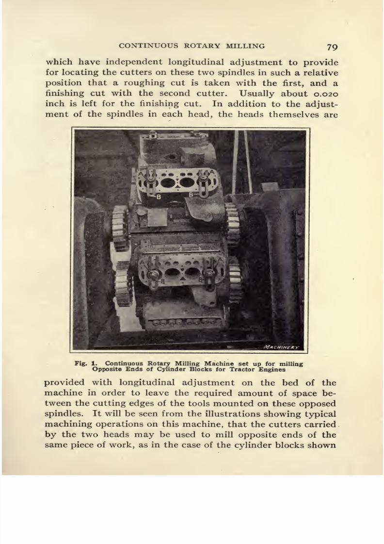
8/13/2019 Production Milling
http://slidepdf.com/reader/full/production-milling 93/296
CONTINUOUS ROTARY MILLING 79
which have independent longitudinal adjustment to provide
forlocating the cutters on these two spindles in such a relative
position that a roughing cut is taken with the first, and a
finishing cut with the second cutter. Usually about 0.020
inch is left for the finishing cut. In addition to the adjust-
ment of the spindles in each head, the heads themselves are
Fig. 1. Continuous Rotary Milling Machine set up for milling
Opposite Ends of Cylinder Blocks for Tractor Engines
provided with longitudinal adjustment on the bed of the
machine in order to leave the required amount of space be-
tween the cutting edges of the tools mounted on these opposed
spindles. It will be seen from the illustrations showing typical
machining operations on this machine, that the cutters carried
by the two heads may be used to mill opposite ends of the
same piece of work, as in the case of the cylinder blocks shown
8/13/2019 Production Milling
http://slidepdf.com/reader/full/production-milling 94/296
80 PRODUCTION MILLING
in Fig. i;
or two rows of castings may be set up on the table
to provide for rough- and finish-milling a single face on eachcasting, an example of such a set-up being shown in Fig. 2.
Provision for Increasing Production. In order to reduce
the non-productive time of the machine to a minimum and
thus obtain the greatest possible output, provision has been
made for feeding the work past the cutters at a suitable rate,
and then rapidly traversing the table through the space be-
tween adjacent pieces of work. If this were not done, a seri-
ous loss of time would result through using the slow feed
movement to bring the next piece of work up to the operating
position. The mechanism for this intermittent feed and rapid
traverse movement is designed similarly to the index me-
chanism of the Cleveland automatic screw machine, so a
detailed description need not be given. Alternate engagement
of the rapid traverse and of the proper rate of feed is accom-
plished automatically by means of tripping dogs mounted on
a drum which rotates with the table and engages the fast or
slow movement according to whether the cutters have just
come into engagement with, or passed out of contact with,
the work. Standard sized milling cutters are always used on
these machines, which are 12 inches in diameter; and the gear
drive between the single pulley on each head and the two
spindles is so worked out that the proper cutting speed is
obtained for the class of work on which the machine is to be
used.
A rotary table is usually designed for each special job to
be done on the machine, although it is frequently possible to
arrange interchangeable work-holding fixtures to adapt the
same table for milling several different pieces. Where this
machineis used for
millinganumber
of differentpieces
of
work, it will often be found economical to have a separate
table with suitable fixtures for holding each class of work, if
the different pieces are milled with sufficient regularity to
pay a satisfactory return on the tool investment. It will be
seen from Fig. 3 that a tapered nose is provided on the spindle
which carries the rotary table. With such a construction, it

8/13/2019 Production Milling
http://slidepdf.com/reader/full/production-milling 95/296
Fig. 2. Milling Water Connections for Tractor Engines. The Same Operation is
performed on Pieces at Both Sides of Table
Fig. 3. Rear View of Continuous Rotary Milling Machine, showing Adjustable
Duplex Cutter-heads and Tapered Spindle Nose for Work-holding Table 81
8/13/2019 Production Milling
http://slidepdf.com/reader/full/production-milling 96/296
82 PRODUCTION MILLING
is easy to bore the different tables to the required fit, and
then their accurate location on the machine is
easilyand
rapidly accomplished. Changing tables in this way is shorter
than setting up a whole new set of work-holding fixtures on
the table. The milling operations performed on these ma-
chines are similar to those described in connection with the
application of continuous rotary milling on knee-type ma-
chines, so it is merely necessary to describe one or two typical
jobs, and the rates of production obtained. These machines
are especially adapted for handling heavy work, and in order
that the high-speed steel inserted-tooth milling cutters used
may be run at a rate of speed and feed approaching their maxi-
mum capacity, all members of the mechanism have been lib-
erally proportioned to withstand severe stresses. On account
of the rapidity with which the work may be fed to the cutters,
it will frequently be found desirable to employ two or more
men to remove milled pieces from the fixtures and to set upfresh blanks in their places. Otherwise, the setting-up time
is so much longer than the actual milling time, that it is neces-
sary to slow down the machine for the operator to perform
his part of the work.
Milling Opposite Ends of Cylinder Blocks. Figure i shows
one of these continuous automatic milling machines in use at
the plant of the Avery Co., Milwaukee, Wis., where it is em-ployed for simultaneously milling the opposite ends of tractor
engine cylinder blocks. In this case, ten castings are mounted
on the table, and the cutters, carried by spindles in the opposed
heads of the machine, rough- and finish-mill both ends of the
same piece of work. The fixtures, or more properly faces of
the table on which the work is carried, are of simple design.
Dowel-pin holes have been drilled in the lower face of the
cylinder blocks, and pins on each station of the table enter
these dowel holes and locate the work ready for milling. There
are two bolts A extending up through the cylinders at oppo-
site ends of each block. These hold the work, and the utiliza-
tion of the U-clamps B under the washers on these bolts makes
it unnecessary to do more than loosen the nuts in order to

8/13/2019 Production Milling
http://slidepdf.com/reader/full/production-milling 97/296

8/13/2019 Production Milling
http://slidepdf.com/reader/full/production-milling 98/296
84 PRODUCTION MILLING
of the table, to load castings into the fixtures and to remove
milledpieces
asthey
come aroundagain
to theloading side.
The rate of production in each case is 400 castings per ten-
hour day.
It will be seen that two different types of water connec-
tions are shown in these illustrations and, owing to the form
of the work, a slight difference is made in the clamps on the
fixtures used for the milling operations. Figure 2 shows
that to release the work from the fixture it is merely necessary
Fig. 5. Face-milling Tractor Engine Cylinder Heads
to loosen the nuts carried by the two bolts A. Beneath each
clamp B there are two springs which raise it out of engagementwith the work as soon as the bolts are released, and thus enable
the milled piece to be withdrawn from the fixture. The rough
cast surface of the work is used as a locating point. At the
front, the work is supported by the lower side of the rectangular
shaped face, while at the back there is a small pad C upon
which the round flange of the water connection is carried;

8/13/2019 Production Milling
http://slidepdf.com/reader/full/production-milling 99/296
CONTINUOUS ROTARY MILLING 85
and the side of this flange rests against block D. Members
C and D of the fixture form the equivalent of a V-block which
supports the thrust developed by the milling cutters and pre-
vents the work from twisting.
For milling the type of water connections which are shown
set up on the machine in Fig. 4, the same form of clamping
mechanism used on fixtures shown in Fig. 2 cannot be em-
ployed, because of the bent form of the work. Consequently,
the tool designer substituted U-clamps B in place of the com-
bination of straps and springs which have just been described.
After the nuts on bolts A have been slightly loosened, these
clamps can be withdrawn and the work removed without
much loss of time. As regards the method of locating and
supporting the work in fixtures shown on this rotary table,
there is little difference from the method described in the
case shown by Fig. 2 . At the front end, the method is exactly
the same in both cases; at the back, the bent end of the workrests on block C and the thrust of the cutters is carried by
block D.
Face-milling Tractor Engine Cylinder Heads. Sufficient
longitudinal adjustment of the heads is provided on the bed
of the Davis & Thompson milling machine so that even in the
case of work of considerable size, on which there is only one
face to be milled, it is possible to construct a work-holdingtable of sufficient width to allow two pieces to be set up side
by side in order to utilize both sets of spindles for machining
the two pieces simultaneously. An arrangement of this kind
is illustrated in Fig. 5, which shows a machine for facing off
the two surfaces A and B on a tractor engine cylinder head.
It is necessary to have these faces definitely located in relation
to each other.
Dowel-pinson the
fixture,which enter holes
drilled in the under side of the head, are used to facilitate
locating these surfaces for milling. After obtaining the desired
location, the work is clamped by two bolts C which extend up
through holes in the top of the head. It will be apparent that
the first operation, to mill face A, is performed with the cast-
ing at the right-hand side of the table; and then the work is
8/13/2019 Production Milling
http://slidepdf.com/reader/full/production-milling 100/296
86 PRODUCTION MILLING
set up at the left-hand side of the table for performing the
second operation, to mill face B. One man is employed to
load and unload castings at each side of the table. By operat-
ing the machine in this way, the rate of production obtained
is 150 cylinder heads per ten-hour working day.
Fig. 6. Face-milling Operation on Main Bearings of Tractor Engine
Machining Main Bearings for Tractors. Figure 6 shows a
continuous rotary milling machine equipped for a facing opera-
tion on the main bearing blocks for tractor engines. In han-
dling this work two cuts are taken, the first of which removes
f inch of metal and leaves approximately V mcn f r the finish-

8/13/2019 Production Milling
http://slidepdf.com/reader/full/production-milling 101/296
CONTINUOUS ROTARY MILLING
ing cut. The operation is performed at a cutting speed of
41 feet per minute with a feed of approximately 2f inches
per minute, and the rate of production obtained averages 15
blocks per hour. The work-holding fixture employed on this
job is of such simple design that its use will be readily under-
stood from the illustration.
Face-milling Bosses on Bomb-container. In Fig. 7 the
machine is shown equipped for rough- and finish-milling the
Fig. 7. Face-milling Bosses at Opposite Ends of Bomb-container
face of a boss at each end of bomb-containers of a form which
is best shown by those lying on the floor at the front of the
machine. These containers are made of steel, and the diameter
of the boss to be milled is approximately 2 inches. Owing
to deviations in the form of the steel castings as they come
to the machine shop, the depth of cut varies from T% inch to
ij inches. In. designing the machine table for this milling
operation, the geared heads were arranged to drive the cutters
at a speed of 43.4 feet per minute, while the rate of feed is 3
inches per minute. Two operators are employed to load and
unload the fixtures. Using the machine under these condi-
tions, the rate of production obtained is seventy milled cast-
6M
8/13/2019 Production Milling
http://slidepdf.com/reader/full/production-milling 102/296
88 PRODUCTION MILLING
ings per hour, or 700 in a ten-hour working day. The rotary
table used on this machine is made in such a way that it is
adapted for only this one milling operation. Semi-cylindrical
seats, of a suitable size to carry the bomb-containers, are
formed in the periphery of the table. As each piece of work
is put into place, a formed plate A is placed over it, and four
bolts B are tightened to secure the work. On account of
the necessity of carefully locating the position of each of these
Fig. 8. Horizontal- spindle Milling Machine equipped with RotaryFixture for Continuous Milling of Inserted-tooth Cutter Blades
pieces in its fixture by means of a gage, two operators were
employed so that the machine could be kept going at a rate
of feed approaching the full capacity of the milling cutter.
Continuous Rotary Fixtures Used on Milwaukee
Milling
Machines. Both the horizontal- and vertical-spindle milling
machines built by the Kearney & Trecker Co. may be equipped
with rotary tables and suitably designed work-holding fixtures
for use in continuous rotary milling operations. The selection
8/13/2019 Production Milling
http://slidepdf.com/reader/full/production-milling 103/296
.CONTINUOUS ROTARY MILLING 89
of machine will be governed chiefly by the nature of the work
to be handled, but generally it will be found that vertical-
spindle milling machines lend themselves better to the peculiar-
ities of continuous rotary milling. The reason will be apparent
after looking over the way in which the machines are set up
for milling operations described in the following paragraphs.
It will be seen that where provision must be made for milling
the upper and lower surfaces of work carried by a rotary
fixture, or for the performance of similar operations, a gang
of cutters can often be mounted to better advantage on the
arbor of a vertical machine than on a horizontal machine.
Milling Inserted-tooth Cutter Blades. Figure 8 shows a
continuous rotary milling fixture employed on a horizontal-
spindle milling machine for machining a 45-degree clearance
angle on inserted-tooth milling cutter blades. This is a simple
operation, and requires only one plain milling cutter. The
fixture is also of simple design, consisting merely of a ring in
which sockets are machined to receive the work and hold it
at the proper angle so that the clearance surface behind the
cutting edge of the blades will be milled to the required angle
of 45 degrees. Each piece of work C is held in the fixture by
means of a strap or clamp A which is tightened by a single
bolt B. As each piece comes around to the loading station,
the operator has only to loosen the bolt, lift the finished piece
of work out of the fixture, and substitute a blank in its place,
after which the clamping bolt is again tightened. One operator
can easily unload and load a fixture of this kind, and produce
2500 of these high-speed steel blades per ten-hour day.
Parts of Different Design Milled in One Fixture. Where
there are a number of different parts of somewhat similar
design to be milled, a saving in the investment in fixtures and
other special tools can be effected by designing a single fixture
for milling several different parts. An example of this class
of fixture design is illustrated in Fig. 9 where it will be seen
that in addition to the work held in the fixture, there are
seven other pieces of somewhat the same general form lying
on the milling machine table. This work-holding fixture has

8/13/2019 Production Milling
http://slidepdf.com/reader/full/production-milling 104/296
90 PRODUCTION MILLING
been so made that it is possible to mill all these different
pieces by simply changing the positions of the bolts and clamps
which secure the work in place. The necessary holes are
drilled and tapped so that changes of clamps to provide for
milling any of the eight different pieces for which the fixture
is adapted may be easily and rapidly accomplished.
The pieces which are shown set up in the fixture are con-
necting link levers for the knee mechanism of Milwaukee
Fig. 9. Continuous Rotary Fixture with Provision for holding
Different Pieces of the Same General Form
milling machines. Two operators are employed one of whom
loosens the clamps and removes the milled pieces from the
fixture, while the other substitutes fresh blanks and clamps
them in place, ready for milling. U-clamps A hold the work,
these clamps being so designed that it is only necessary for
the operator to loosen nut B to withdraw the clamp. After
this has been done, the hole in the work is of sufficient size to
enable it to be lifted over the nut. Much time is saved by

8/13/2019 Production Milling
http://slidepdf.com/reader/full/production-milling 105/296
CONTINUOUS ROTARY MILLING
avoiding the necessity of screwing the nut all the way off the
bolt. The operation in this case consists of spot-milling the
round face on an arm on the work. This face is 2 inches in
diameter and the depth of cut averages | inch. The material
is malleable iron, and two operators engaged in loading and
unloading the fixture on this machine are able to turn out
10,000 pieces in a ten-hour working day.
Fixture for Performing More than One Operation on the
Same Part. In addition to designing work-holding fixtures
Fig. 10. Continuous Rotary Fixture designed to perform TwoSuccessive Operations. This Illustration shows the
First Milling Operation
to provide for milling operations on a number of different
parts, it is often possible to use the same fixture for two or
more operations on the same part. Where this practice is
adopted, it will usually be found most satisfactory to mill
several thousand pieces of work; and after these have been
milled, it is merely necessary to change the cutters on the

8/13/2019 Production Milling
http://slidepdf.com/reader/full/production-milling 106/296
PRODUCTION MILLING
arbor of the machine for the second operation, and to make
subsequent changes for any additional operations which are
needed to complete the work. An example of the way in
which a single work-holding fixture may be utilized for two
successive milling operations is illustrated in Figs. 10 and n.
The first operation on the work consists of milling the head
to a semi-cylindrical form, as shown in Fig. 10; and after this
Fig. 11. Pieces milled as shown in Fig. 10 are reset in the SameFixture at an Angle of 90 Degrees from Original Posi-
tion, Ready for performing the Second Operation
has been done on all of the pieces, the work is turned through
an angle of 90 degrees and set up in the position shown in Fig.
u, ready to have a slot milled transversely across the head.
The first operation is performed with a formed milling
cutter, and a narrow side milling cutter is used for the second
operation. The ends of the pieces that can be seen at A pro-
jecting inside the ring body of the fixture show how the work
is clamped. Here it will be apparent that a strap B, actuated

8/13/2019 Production Milling
http://slidepdf.com/reader/full/production-milling 107/296
CONTINUOUS ROTARY MILLING 93
by a single clamping bolt C, engages the inner ends of two
pieces of work so that both are secured in place by one bolt.
After the milling operation has been performed, it is merely
necessary to loosen this bolt about one-half turn, draw the
pieces of work out, and push other blanks into the holes which
have been made vacant to receive them. On the first opera-
tion, the rate of production is 2000 pieces in a ten-hour work-
Fig. 12. Straddle-milling Side Faces of the Head and of the
Movable Jaw of Adjustable Wrenches
ing day, while the second operation may be run at a higher
rate of feed, making it possible to produce 3000 pieces per
day. These parts are roller plungers for the feed trip on Milwaukee milling machines, and are made of steel. One
operator is able to load and unload the fixture.
Straddle-milling Adjustable Wrenches. In manufactur-
ing adjustable wrenches, one maker forges the head and handle
of the wrench in a single piece, and carries machining opera-

8/13/2019 Production Milling
http://slidepdf.com/reader/full/production-milling 108/296
94 PRODUCTION MILLING
tions on the adjustable jaw up to a point where this member
and the handle are ready to be assembled together. To pro-
duce tools of a satisfactory appearance, it is necessary for
the side faces of the head and adjustable jaw to be at the
same level. This can be done by using a vertical-spindle
milling machine equipped with a gang of inserted-tooth
straddle-milling cutters, and a rotary fixture of the design
Fig. 13. Face-milling Seat of Crankshaft Bearing Caps
illustrated in Fig. 12. An important feature of the design of
this fixture is the provision for extremely rapid operation. As
each station on the fixture comes around to the front, after
the milling operation, it is merely necessary for the operatorto raise lever A. This lever is carried by a short stud, on the
opposite end of which an eccentric B is mounted, this eccen-
tric being utilized to clamp the work down on a hardened
block C. To prevent the work from being twisted by the
torque of the milling cutters, pin D supports the work at
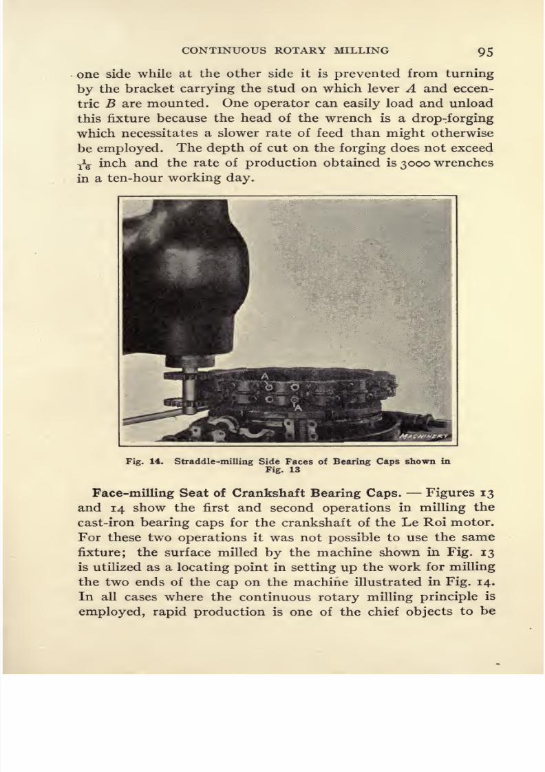
8/13/2019 Production Milling
http://slidepdf.com/reader/full/production-milling 109/296
CONTINUOUS ROTARY MILLING 95
one side while at the other side it is prevented from turning
by the bracket carrying the stud on which lever A and eccen-
tric B are mounted. One operator can easily load and unloadthis fixture because the head of the wrench is a drop-forging
which necessitates a slower rate of feed than might otherwise
be employed. The depth of cut on the forging does not exceed
fg inch and the rate of production obtained is 3000 wrenches
in a ten-hour working day.
Fig. 14. Straddle-milling Side Faces of Bearing Caps shown in
Fig. 13
Face-milling Seat of Crankshaft Bearing Caps. Figures 13
and 14 show the first and second operations in milling the
cast-iron bearing caps for the crankshaft of the Le Roi motor.
For these two operations it was not possible to use the same
fixture; the surface milled by the machine shown in Fig. 13
is utilized as a locating point in setting up the work for milling
the two ends of the cap on the machine illustrated in Fig. 14.
In all cases where the continuous rotary milling principle is
employed, rapid production is one of the chief objects to be

8/13/2019 Production Milling
http://slidepdf.com/reader/full/production-milling 110/296
96 PRODUCTION MILLING
obtained; and as the setting up time is frequently greater than
the actual cutting time, it is desirable to have the clamping
mechanism of a fixtureoperate
asrapidly
aspossible. A good
example of the provision for setting up and removing work
with the minimum loss of time is shown by the fixture illus-
trated in Fig. 13. At each station in this fixture there are
four pins, two of which are shown at A and B, and each of
these pins supports the work under the flanges at each end.
Two U-clamps C, which are secured by bolts D, hold the
Fig. 15. Face-milling Plunger Pump Bases on Continuous Rotary
Milling Machine
work down. The rate of production secured is 5000 castings
in a ten-hour day.
After the milling has been done, a half turn of each of the
bolts D will loosen the clamps sufficiently so that they canbe drawn back, thus enabling the milled piece to be removed
from the fixture and another casting substituted. The surface
milled on the machine shown in Fig. 13 is used as the locat-
ing point for the second operation on these bearing caps. It
will be apparent that the two ends of the work are simultane-

8/13/2019 Production Milling
http://slidepdf.com/reader/full/production-milling 111/296
CONTINUOUS ROTARY MILLING 97
ously milled by means of a pair of straddle cutters (see Fig.
14), and that the milling fixture consists merely of a ring
carried by a rotary table, which is furnished with bolts to
secure the castings in place on the fixture. In this case, it
was impossible to avoid having the length of time required
for setting up and removing the work rather longer than might
be expected. The holes through the bearing caps are not
large enough to provide clearance for nuts used in conjunction
with slotted washers, so the two nuts A used for holding the
work have to be screwed all the
wayoff the bolts. Even
so,the rate of production obtained is 5000 castings per day with
a depth of cut averaging f inch, taken from each of the end
faces.
Face-milling Plunger Pump Bases. Continuous rotary
milling is especially adapted for machining pieces of moder-
ately small size, but frequently face-milling can be done on
machines equipped with rotary fixtures. Figure 15 shows a
vertical-spindle Milwaukee milling machine used at the
plant of the Madison-Kipp Lubricator Co., Madison, Wis.,
for machining the bases of pump bodies. The pieces to be
milled have two holes drilled in them, which are utilized as
locating points by slipping the work over pilot A and pin B.
At each station there is also a supporting bracket C, which
is pivoted so that it may be swung around behind the casting
and then pushed inward by means of an eccentic at the end
of lever D. Hole E in the bracket receives the outer end of
pilot A, thus helping to steady the work and eliminating
vibration. In milling these faces, the average depth of cut is
approximately f inch, and the size of surface to be milled is
2 by 3 inches. With one operator engaged on the machine,
these gray iron castings can be milled at the rate of 800 per
ten-hour working day.
Straddle-milling Shanks of Tappet Valves. Figure 16
illustrates a vertical-spindle milling machine with a rotary
fixture for milling two flats at the end of the shank of steel
tappet valves for a motor. The design consists simply of two
V-blocks at each station, which receive the shanks of the valves,

8/13/2019 Production Milling
http://slidepdf.com/reader/full/production-milling 112/296
98 PRODUCTION MILLING
and a strap A and clamping bolt B which hold both pieces of
work in place. The maximum depth of cut in this instance is
only TV inch, so the machine can be run at a high rate of feed.
The setting-up time, therefore, becomes the determining
factor in production, and in order to operate the machine
under the most favorable conditions it is necessary to have
three operators engaged in removing milled valves and sub-
stituting fresh blanks in their places. Used in this way, one
machine is able to mill 25,000 valves in ten hours.
Fig. 16. Straddle-milling Two Flats on Shanks of Tappet Valves
Continuous Rotary Milling on Becker Machines. Vertical-
spindle milling machines built by the Becker Milling Machine
Co., are used in many plants in connection with rotary tables
for applying the continuous principle to milling operations.
Where work has to be milled at both ends, an important fea-
ture of the equipments designed and built by this company is
that an auxiliary vertical spindle may be provided on the
machines, so that it is unnecessary to reset the work for a
second operation on the opposite end from that previously
milled. Despite careful designing of the clamping mechanism

8/13/2019 Production Milling
http://slidepdf.com/reader/full/production-milling 113/296

8/13/2019 Production Milling
http://slidepdf.com/reader/full/production-milling 114/296
100 PRODUCTION MILLING
the designer adopted the use of an auxiliary spindle on the
machine so that both ends of the connecting-rods could be
milled simultaneously. Then he went a step further by setting
up two milling cutters on each spindle, in order to make pro-
vision for milling both sides of the connecting-rods at the
same time. The arbors are piloted at their lower ends to
maintain accurate alignment and perfect rigidity. After it
had been placed in service, the designer made a slight change
in working out the details of this fixture as used for machining
motorconnecting-rods,
shown in Fig. 18.
Fig. 18. Fixture for straddle-milling Both Ends of Motor
Connecting-rod Forgings simultaneously
Designing Fixtures to Reduce the Load on Clamps. In
the case of the fixture shown set up on the machine in Fig. 17,
it will be seen that each connecting-rod is placed in a radial
position and the rotary table on the machine is arranged to
run in a clockwise direction. Provision is made for carrying
ten forgings in the fixture. As the connecting-rod forgings
are fed under the cutters, the milling operation on one end of
a piece of work is completed before the opposite end is fed
up to the cutters. As a result, the cutters exert a thrust on
the work first in one direction and then in the other, which
imposes an unnecessarily severe load on the clamps. To re-
duce this load, the equipment was designed as shown in Fig.
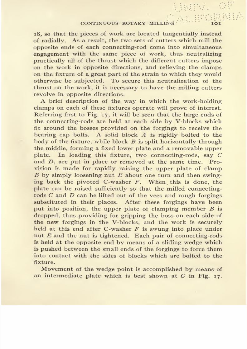
8/13/2019 Production Milling
http://slidepdf.com/reader/full/production-milling 115/296
CONTINUOUS ROTARY MILLING IOI
18, so that the pieces of work are located tangentially instead
of radially. As a result, the two sets of cutters which mill the
opposite ends of each connecting-rod come into simultaneous
engagement with the same piece of work, thus neutralizing
practically all of the thrust which the different cutters impose
on the work in opposite directions, and relieving the clamps
on the fixture of a great part of the strain to which they would
otherwise be subjected. To secure this neutralization of the
thrust on the work, it is necessary to have the milling cutters
revolve in
oppositedirections.
A brief description of the way in which the work-holding
clamps on each of these fixtures operate will prove of interest.
Referring first to Fig. 17, it will be seen that the large ends of
the connecting-rods are held at each side by V-blocks which
fit around the bosses provided on the forgings to receive the
bearing cap bolts. A solid block A is rigidly bolted to the
body of the fixture, while block B is split horizontally through
the middle, forming a fixed lower plate and a removable upper
plate. In loading this fixture, two connecting-rods, say C
and D, are put in place or removed at the same time. Pro-
vision is made for rapidly raising the upper plate of clamp
B by simply loosening nut E about one turn and then swing-
ing back the pivoted C-washer F. Whenvthis is done, the
plate can be raised sufficiently so that the milled connecting-
rods C and D can be lifted out of the vees and rough forgings
substituted in their places. After these forgings have been
put into position, the upper plate of clamping member B is
dropped, thus providing for gripping the boss on each side of
the new forgings in the V-blocks, and the work is securely
held at this end after C-washer F is swung into place under
nut E and the nut is tightened. Each pair of connecting-rods
is held at the opposite end by means of a sliding wedge whichis pushed between the small ends of the forgings to force them
into contact with the sides of blocks which are bolted to the
fixture.
Movement of the wedge point is accomplished by means of
an intermediate plate which is best shown at G in Fig. 17.

8/13/2019 Production Milling
http://slidepdf.com/reader/full/production-milling 116/296
'
102 PRODUCTION MILLING
This plate is beveled on its inner edge to engage a correspond-
ing beveled face on the outer edge of wedge H. Tightening
the nut above plate G forces the plate downward, and the
beveled edge of plate G acting against the beveled face of
wedge H forces the wedge between the inner ends of the
connecting-rods, thus holding them firmly in place against
the sides of the fixed blocks. Each of the wedges H is held
on the body of the fixture by a screw /, which fits into an
elongated hole. This arrangement provides for holding the
wedgein
placeand at the same time allows it the
necessarylateral movement.
How Quick-acting Fixtures Increase Production. On the
fixture shown in Fig. 18 two forgings are set up at one time,
as in the preceding fixture. Fourteen forgings are carried by
the fixture, and the pieces are milled on four surfaces. The
machine is operated with a feed of 4 inches per minute and
forty forgings are machined per hour. The work is done on
a two-spindle machine, with two cutters on each arbor to
provide for milling all four surfaces on the work simultane-
ously. In this case, each pair of connecting-rod forgings is
held by two clamp members A, which are securely bolted to
the fixture, and a pivoted clamp member B. The illustration
shows that these clamps are made with vees to receive the
bosses on the forgings in which the bearing cap bolt holes are
to be drilled. When two forgings have been dropped into
place in the fixture, bolt C is tightened, pushing the connect-
ing-rod forging in front of clamp B up firmly into contact
with clamp A. At the same time, clamp B swings back on
its pivot to provide for securely clamping the connecting-rod
forging behind this clamp against the second clamp A. At
the inner end the forgings are secured by a strap D, held
down by nut E, which is tightened by a T-wrench F. Provi-sion is made for eliminating the possibility of straps D being
set in a position where they will interfere with the milling
cutters. Two forgings are held in place in this fixture by
simply tightening bolts C and E, so that the operation of
setting up the work is extremely rapid. The small block G

8/13/2019 Production Milling
http://slidepdf.com/reader/full/production-milling 117/296
CONTINUOUS ROTARY MILLING I03
and pin H, provided at each station on the fixture, fit into
the channel in the connecting-rod forging; block G constitutes
an end-stop for locating the work, while pin H affords a sup-
port for the forging to prevent it from being sprung by the
pressure of the cutter.
A better idea of the construction of clamping bolts C will
be obtained by referring to Fig. 19. Here it will be seen that
the bolts C are threaded into the tapped holes in V-blocks /,
which slide in holes machined in the pivoted clamps B, to
SECTION Y-YMachinery
Fig. 19. Details of Work-holding Fixture shown in Fig. 18
come into engagement with the large ends of the connecting-
rods and secure them in place in the fixture.
Application of Continuous Rotary Milling Principle to Ma-
chining Large Pieces. Although continuous rotary milling
is especially adapted for machining pieces of relatively small
size, the method may also be used for larger pieces. Figure
20 shows a fixture designed for machining the differential gear
housing for an automobile. The work is malleable iron, and
each casting weighs approximately 40 pounds. In this case
only two pieces are set up in the fixture at one time, the method
7M

8/13/2019 Production Milling
http://slidepdf.com/reader/full/production-milling 118/296
IO4 PRODUCTION MILLING
of operation being such that the single large face-milling cutter
is working on one casting while the operator is removing the
other piece which has just been milled and substituting afresh casting in its place. Each of the two stations on the
work-holding fixtures is equipped with two trunnion cradles
Fig. 20. Milling Differential Gear Housings showing an Ap-plication of the Continuous Rotary Principle to milling
Large Castings
A, so that the work can be dropped into place and held down
by means of straps B at each end. In this case the table is
arranged to rotate in a counterclockwise direction so that the
milling cutter first engages the work at the side nearest to the
center of the table. To prevent the work from rotating,
each of the castings is supported on the inner side, so that
the pressure of the milling cutter cannot cause these castings

8/13/2019 Production Milling
http://slidepdf.com/reader/full/production-milling 119/296
CONTINUOUS ROTARY MILLING
to rotate on their points of support. The rate of production
is twenty-two pieces per hour.
Face-milling Aluminum Crankcases. Figure 2 1 shows a
fixture designed for facing off the underside of an aluminum
Fig. 21. Continuous Rotary Fixture designed for performing a
Face-milling Operation on Aluminum Crankcase Castings
Fig. 22. Face-milling the Joint between Two Halves of FanPulley Castings
crankcase on a single-spindle milling machine equipped for
operation on the continuous rotary principle. One crankcase
casting is shown set up in place, and at the front of the fixture
is illustrated the way in which the work is secured in position

8/13/2019 Production Milling
http://slidepdf.com/reader/full/production-milling 120/296
io6 PRODUCTION MILLING
for milling. Only two castings are held by this fixture. The
underside of the castings has already been face-milled, and
this surface is used as the locating point, finished pads A, B,
and C on the fixture being employed for this purpose. The
casting is dropped into place on these pads and end-stops D }
which are beveled on the underside, hold the casting down
on the locating pads when clamping screw E is tightened.
When the work has been set up the operator reaches in through
Machinery
Fig. 23. Details of Fixture illustrated in Fig. 22
holes in the side of the crankcase casting and tightens straps
F and G to hold the work securely down on the fixture for mil-
ling. The estimated rate of production is three pieces per hour.
Face-milling Joint between Two Halves of Fan Pulley
Castings. Figures 22 and 23 show a continuous milling
rotary fixture designed for use in machining the joint between
the two halves of fan pulleys. This fixture holds sixteen
pieces of work, and is arranged in a somewhat different manner
from those already described. It will be seen that each sta-

8/13/2019 Production Milling
http://slidepdf.com/reader/full/production-milling 121/296

8/13/2019 Production Milling
http://slidepdf.com/reader/full/production-milling 122/296
io8 PRODUCTION MILLING
and held firmly in position ready for the milling operation.
Clamps B and C slide on pins D and E, respectively, to pre-
vent them from turning, and the clamps are set at an angleto provide for forcing the work down into the fixture. Springs
F Fig. 23, are placed under the clamps to raise them out of
Machinery
Fig. 25. Details of Work-holding Fixture illustrated in Fig. 24
engagement with the work when the bolts are loosened, thus
increasing the speed of operation. By simply tightening two
bolts two pieces of work are secured in position on the fixture,
so that it is possible to set up the work for milling and remove
it without entailing much loss of time. The output is more
than sixty pieces per hour.

8/13/2019 Production Milling
http://slidepdf.com/reader/full/production-milling 123/296

8/13/2019 Production Milling
http://slidepdf.com/reader/full/production-milling 124/296
110 PRODUCTION MILLING
these trunnions are held. Above each pair of vees there is a
spring clip A which holds the work in position until the clamp-
ing device on the fixture has been tightened to secure the workfor milling. Two pieces are set up in the fixture and removed
at the same time. After the forgings have been pushed under
spring clips A, clamps B are tightened to secure the two forg-
ings in the V-blocks. Rotation of the forgings due to the torque
of the milling cutters is prevented by pins C against which the
sides of the yoke forgings come into contact. By straddle-
milling the four faces onthese
pieces simultaneously, the rateof production is 195 shifter yokes per hour. A better idea of
details of the fixture design will be obtained by referring to
Fig. 25. Attention is called to the springs for releasing clamps
B when the bolts are loosened.
Milling Both Sides of a Cover Plate. In Fig. 26 is illus-
trated a fixture designed for facing both sides of an automobile
starter cover on a machine equipped for continuous rotary
milling. In working out the design, it was found that ample
production could be obtained from one single-spindle machine.
To enable it to be operated continuously without changing
the fixtures for milling the two sides of the work, the fixture
was designed with provision for milling one side of the starter
cover while held at one station and then transferring this piece
of work to an adjacent station on the fixture ready for milling
the opposite side. The illustration shows that alternate
stations are arranged for holding the work for the first and
second operations, respectively, and the fixture can hold seven
pieces of work in each position.
For the first operation, the work is set up to mill face A,and
for this purpose the under side of the rough casting is located
against three stops B which*
constitute the equivalent of a
vee into which the casting is forced by means of clampingscrew C. This screw is pointed both inward and downward,
so that tightening it serves the double purpose of forcing the
work into the vee formed by the three locating stops, and of
holding the work down on the faces of these stops. After the
first operation, the work is turned over, ready for milling sur-

8/13/2019 Production Milling
http://slidepdf.com/reader/full/production-milling 125/296

8/13/2019 Production Milling
http://slidepdf.com/reader/full/production-milling 126/296
112 PRODUCTION MILLING
used for these two milling operations. These cutters are so
mounted on the piloted arbor that spaces are left of the proper
width for milling the faces at opposite ends of the work. Theinteresting feature of this fixture is the provision for reversing
the work end for end, and still having the milling cutters
properly located to take care of the offset on the brake levers.
At each station two brake levers are mounted in a block, these
pieces of work being held down by a cover plate A which is
tightened down on the work by first adjusting the position of
a C-washer B and then tightening clamping screw C.
The work-holding block is pushed in against two locating
plugs Z>, which are beveled in such a way that they serve the
double purpose of locating the block in the desired position
and holding it down on the fixture when capstan screw E is
tightened. The two forgings are located in the block by a
wedge M which forces them into contact with a pin K and
lug /. Lug / and lug L, which is at the opposite end of the
block, are so placed that they take the thrust of the cutters.
The block is first pushed into position with the large end of
each brake lever on the inside, so that this end of the work
comes into place between cutters F and G. After the work
has been milled at this end and the work-holding block has
come around to the loading position, it is released by loosen-
ing clamp screw E, and the block is next turned end for end
and secured in that position in the fixture. Then, when the
rotary table has again brought the work around to feed under
the cutters a second time, the small end of the brake levers
goes between cutters H and 7 which are properly spaced to
provide for milling the faces at the small end of the work.
The work of setting up and milling these forgings can be
handled very quickly. The actual output is more than eighty
brake lever
forgings per hour,which are
completelymilled
on four surfaces.
Fixture for Milling Clutch Shaft Bearings. Figure 28
shows the use of a continuous rotary milling fixture designed
for facing off the base of clutch shaft bearings. This fixture
has capacity for holding sixteen pieces of work. In order to

8/13/2019 Production Milling
http://slidepdf.com/reader/full/production-milling 127/296
CONTINUOUS ROTARY MILLING 113
provide for machining the bases of these parts exactly level,
which is an essential feature, an interesting form of equaliz-
ing device was developed. On each clutch shaft bearing
there are two bosses A supported by plungers B in such a
way that they provide for leveling up the work. When the
milling cutter faces off the under surface, it will be apparent
that this surface will be parallel with bosses A. At their
lower ends plungers B are secured to a block C and this block
also carries a C-shaped plate D which serves as the equivalent
of a C-washer for
clampingnut E.
Toset
upapiece
of
work
Fig. 28. Continuous Rotary Milling Fixture with Equalizing
Device for locating Clutch Shaft Bearings
in this fixture, the casting is dropped into place after which
lever F is raised, this lever being pivoted at a point on the
inside of the main casting of the fixture. As a result of raising
lever F, plungers B level up the work and at the same time
plate D is slipped under nut E. Then by simply tightening
this nut about one-half turn, the work is secured in place
ready for milling. It is possible to secure a high rate of pro-
duction with a fixture which can be operated so rapidly.
The operation is performed on a single-spindle machine with
one face-milling cutter carried on the arbor.
Fixtures for Milling Six Surfaces on Spring Shackles. In
Figs. 29 to 32, inclusive, there are shown two fixtures used for

8/13/2019 Production Milling
http://slidepdf.com/reader/full/production-milling 128/296
H4 PRODUCTION MILLING
milling six surfaces on cast-iron spring shackles of the form
shown in Figs. 29 and 31. In milling these parts, four steps
are required. With the work set up in the fixture shown in
Figs. 29 and 30, using two straddle-milling cutters mounted
on a single-spindle machine, the first step is to mill faces A
and B. Then the shackle on which these faces have been
milled is turned over in the fixture and again carried between
the milling cutters for facing off surfaces C and D.
The next
step is to take the partially milled shackle to machines equipped
Fig. 29. Fixture designed for straddle-milling Faces A, B, C,and D of Spring Shackles
with fixtures of the type shown in Figs. 31 and 32. These
single-spindle machines are equipped with one facing cutter,
and at the first revolution of the fixture, surface E is milled.
The work is then turned over, and at the second revolution
of the fixture, surface F is finished, thus completing the milling
operations.
The details of the design of the work-holding fixtures and
method of handling the work are as follows: Figures 29 and
30 show that the fixture holds sixteen spring shackles. Each
shackle is dropped into one of the stations of this fixture with

8/13/2019 Production Milling
http://slidepdf.com/reader/full/production-milling 129/296
CONTINUOUS ROTARY MILLING
the arms projecting inward, and steel plates G are arranged
to bear against the sides of the upper and lower bosses on
which it is required to mill four surfaces, A and Bor
Cand
Z>,
with the work - set up in this fixture. Endwise location is
accomplished by having either surface E or F rest against
the bed of the fixture. Two shackles are dropped into place
in the fixture or removed at the same time. After two cast-
Machinery
Fig. 30. Details of Work-holding Fixture shown in Fig. 29
ings have been put into place, screw H is tightened. Figure
30 shows that each of these screws is threaded into V-blocks I;
the ends of these V-blocks will also be seen in Fig. 29. Bytightening screw H the two pieces of work are forced inward
so that they are engaged by the tapered ends of plates G.
Lever / is then thrown over. This lever operates a quick-
acting cam mechanism which tightens strap K down on sur-
face or F of the work, as the case may be, thus securing it

8/13/2019 Production Milling
http://slidepdf.com/reader/full/production-milling 130/296
n6 PRODUCTION MILLING
in place for milling. After surfaces A and B have been milled,
the work is turned over end for end and surfaces C and D are
milled at the next revolution of the work-holding fixture.
The material is cast iron and the fixture is rotated at a speed
which feeds the work to the cutters at a rate of 4 inches per
minute. The rate of production, milling four surfaces, is
more than eighty pieces per hour. At L there is shown a gage
used for checking the accuracy of the distance between faces
A and B or C and D, as this dimension has to be held within
specified limits. For the two final milling operations on these
Fig. 31. Continuous Rotary Milling Fixture for milling Faces
E and F of Spring Shackles
spring shackles, surfaces B and C, Fig. 30, are used as the
locating points. These surfaces straddle a finished ring extend-
ing all the way around the fixture, Figs. 31 and 32, so that
they are in close contact with surfaces M and N machined onthe upper and lower sides of the ring. This provides for end-
wise location of the work, to obtain the desired relationship
between all of the six milled surfaces. For clamping the work,
the spring shackle castings are slid inward until engagement
is made with plugs O, P, and Q, which form the equivalent of

8/13/2019 Production Milling
http://slidepdf.com/reader/full/production-milling 131/296
CONTINUOUS ROTARY MILLING 117
two V-blocks. As in the case of the preceding fixture, two
spring shackle castings are set up or removed at a time. After
the work has been pushed into place between plugs O and Por P and Q, nut R is tightened to bring strap S against the
backs of the two spring shackles. This strap is tapered on
its inner side so that provision is made for clamping the two
pieces of work between the two tapered surfaces on strap 5
and corresponding tapered surfaces on lugs T and U which
Machinery
Fig. 32. Details of Work-holding Fixture shown in Fig. 31
project out from the body of the fixture. A compression spring
V is located behind each of the straps 5, so that in removing
the work it is merely necessary to loosen nut R, and the strap
is automatically pushed back from the work by the spring.
The fixture is designed to hold twenty-eight pieces of work.
After surface E has been machined the work is turned over
end for end to provide for milling surface F. The fixture
feeds the work to the cutters at 4 inches per minute. In per-
forming these two operations the rate of production is sub-
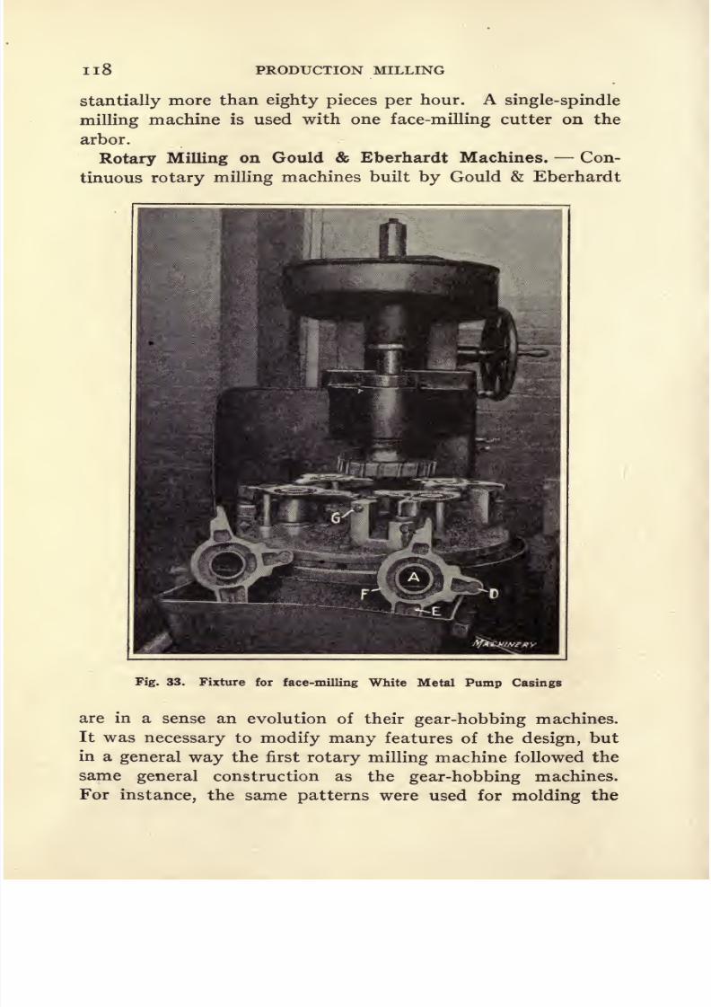
8/13/2019 Production Milling
http://slidepdf.com/reader/full/production-milling 132/296
n8 PRODUCTION MILLING
stantially more than eighty pieces per hour. A single-spindle
milling machine is used with one face-milling cutter on the
arbor.
Rotary Milling on Gould & Eberhardt Machines. Con-
tinuous rotary milling machines built by Gould & Eberhardt
Fig. 33. Fixture for face-milling White Metal Pump Casings
are in a sense an evolution of their gear-hobbing machines.
It was necessary to modify many features of the design, but
in a general way the first rotary milling machine followed the
same general construction as the gear-hobbing machines.
For instance, the same patterns were used for molding the

8/13/2019 Production Milling
http://slidepdf.com/reader/full/production-milling 133/296
CONTINUOUS ROTARY MILLING IIQ
castings for the beds of both types of machine, and other
standardized units of the hobbing machine were employed in
the milling machine construction. Experience showed, how-
ever, that continuous rotary milling machines had to with-
stand more severe service than gear-hobbing machines, so the
Fig. 34. Continuous Rotary Fixture for straddle-milling the
Ends of Wrist-pins
design of the latter was revised to afford the required rigidity
at points where unusually severe stresses must be carried.
It will be seen from Figs. 33 and 34 that the spindle head is
mounted on the column with sufficient adjustment so that
the head may be set in any desired relation to the work for
8 M

8/13/2019 Production Milling
http://slidepdf.com/reader/full/production-milling 134/296
120 PRODUCTION MILLING
using a single face-milling cutter, a gang of straddle-milling
cutters, or any other combination required for the most rapid
production of various classes of work. In place of the work-
holding table which supports the gear blank on a bobbing
machine, a rotary table was furnished on the milling machine,
on which a continuous circular work-holding fixture may be
mounted. The method of driving this table and of adjusting
its position on the bed of the machine are similar to the method
of driving and adjusting the table of the standard gear-hobbing
machines of this company's manufacture.Range of Work Handled. Figures 33 to 40 will give a
good idea of the classes of work which can be handled on this
type of continuous rotary milling machines, and also of the
methods of setting up and operating. These examples of shop
practice have been selected with several ideas in mind. In
the first place, they show fixtures used for milling a variety
of different sized pieces, ranging from the white metal
pumpcastings shown in Fig. 33, of which only four may be mounted
in the fixture at a time, up to the wrist-pins shown in Fig. 34,
of which forty-eight can be held at a time. Other interesting
features are the variety of methods adopted for holding the
work, and the various combinations of cutters used.
The work-holding fixture shown on the machine in Fig. 33
consists of a pilot at each station on the fixture, over which
the previously bored work is dropped, and four posts which
engage the under side of the various overhanging sections of
the work to prevent them from being distorted by the pres-
sure of the milling cutters. Frequently it is desirable to adopt
the principle of mounting work on the upper surface of a con-
tinuous rotary fixture, but the more generally applied method
is to hang the work around the periphery of the fixture so that
it may be passed between cutters mounted on the arbor. Thelatter method is usually applied where there are several sur-
faces on the work to be milled by means of a gang of straddle-
milling cutters. Such a fixture is shown in Fig. 37, where it
will be seen that there are four surfaces A, B, C, and D on the
work to be milled by means of a gang of straddle-milling cut-

8/13/2019 Production Milling
http://slidepdf.com/reader/full/production-milling 135/296
CONTINUOUS ROTARY MILLING 121
ters. In this case sufficient overhang is provided to allow the
work to be fed between such a gang of cutters without any
danger of interference with the fixture.
Milling White Metal Pump Casings. In the case of the
white metal pump casings shown in Fig. 33, hole A has been
finish-bored when the castings come to the machine. This
hole is utilized as a locating point, the castings being dropped
over pilots on the fixture which fit closely into holes A . For
any face-milling operation, the work must be so supported
that thereis
no danger of the pressure of the milling cutters
causing the work to be sprung out of shape, thus producing
subsequent trouble in assembling. Support for the work in
face-milling operations is especially important in the case
of pieces with overhanging arms, flanges, etc., which are
likely to be deflected through the application of pressure if
poorly supported. The pump casings shown in Fig. 33 are
a typical example of such work, because the three arms, C, D,
and E and the flange F must be supported from beneath.
After each casting is dropped over the pilot, it slides down
until the arms and flanges of the work are engaged by posts
projecting up from the bed of the fixture. Then cap-screw
G is tightened to clamp the work. As each casting is ade-
quately supported from underneath and the entire pressure of
the milling cutters is downward, it is merely necessary for this
screw to prevent vibration from having a tendency to raise
the work off its supporting points.
Face-milling Connecting-rods on Continuous Rotary Ma-
chines. At the plant of the Ford Motor Co. in Walkerville,
Ont., continuous rotary milling machines of this type are
tooled up as shown in Fig. 35 for facing off the surfaces of
crankshaft bearing yokes, which are left rough at the time the
rods are forged. This illustration shows that there are ten
stations on the fixture, in each of which two connecting-rod
forgings may be mounted so that a total of twenty forgings
are set up. To hold two forgings in place it is merely necessary
to place them behind strap A and tighten bolt B. The forgings
to be milled will be seen at C, and in setting up these forgings

8/13/2019 Production Milling
http://slidepdf.com/reader/full/production-milling 136/296
122 PRODUCTION MILLING
two pins (not shown in the illustration) fit into the wrist-pin
bearing at the lower end of each forging. This provides for
supporting the thrust of the milling cutter, and when strapA has been tightened back on the work, the operator gives
the pieces no further attention until they come around to the
Fig. 35. Continuous Rotary Milling Machine equipped for face-
milling Ends of Yokes on Connecting-rod Forgings
loading point again, milled and ready to be removed from
the fixture. As it is merely necessary to loosen bolt B slightly
to remove the work, very little time is consumed.
Rough-milling the Teeth of Bevel Gear Blanks. Generat-
ing planers of the type built by the Gleason Works are used
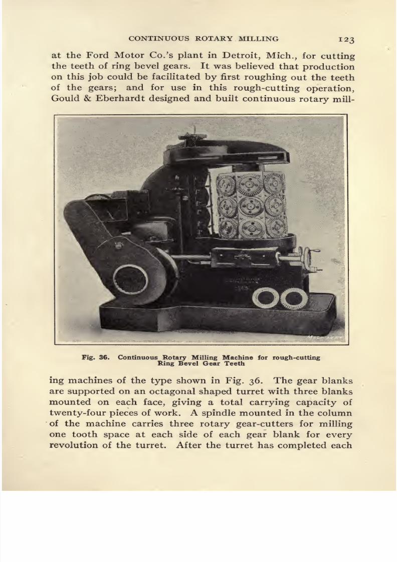
8/13/2019 Production Milling
http://slidepdf.com/reader/full/production-milling 137/296

8/13/2019 Production Milling
http://slidepdf.com/reader/full/production-milling 138/296

8/13/2019 Production Milling
http://slidepdf.com/reader/full/production-milling 139/296
CONTINUOUS ROTARY MILLING 125
tooth planer. In operating the Gould & Eberhardt milling
machines, the gear blanks are set up in rotation so that they
are finished in consecutive order instead of having all of the
twenty-four blanks carried by the turret finished at one time.
This keeps the machine operator constantly employed setting
up blanks and removing finished gears from the machine,
instead of having to shut down the machine while twenty-four
finished gears are removed and the same number of blanks
set up in their places. One operator is able to attend to two
machines used under these conditions, and the rate of pro-
duction is one rough-cut gear in approximately three minutes.
Straddle-milling Wrist-pins. For milling wrist-pins for
the Ford motor, use is made of continuous rotary milling ma-
chines equipped with fixtures shown in Fig. 34, which have a
capacity for holding forty-eight pins. There are twenty-four
stations on the fixture, each of which is furnished with a clamp-
ing strapA held
againstthe work
bya
singlebolt B.
Twowrist-pins C are held by the strap, so that both pieces of work
may be set up and held in place on the fixture by merely
tightening the bolt B. Semi-cylindrical shape pockets are
machined around the periphery of the fixture to receive the
pieces of work, and similar pockets are milled on the inside of
straps A. As these pockets fall just short of being a full half
cylinder, two pieces of work can be clamped between the
strap and body of the fixture by tightening a single bolt. As
it is merely necessary to loosen bolt B about one-half turn in
order to lift the two wrist-pins C out of the fixture and substi-
tute other blanks, the fixture can be manipulated rapidly.
Supporting Castings for Milling Four Faces Simultaneously.
-A fixture is shown in Fig. 37 used in straddle-milling the
faces A, B, C, and D of two lugs on cast-iron brackets, which
are carried on the periphery of the fixture with sufficient over-
hang to allow the work to come between a gang of four straddle-
milling cutters on the milling machine arbor. The piece of
work seen lying in front of the fixture in this illustration shows
that there is a flange E which extends backward, and this
flange is used as the supporting member for clamping the work.

8/13/2019 Production Milling
http://slidepdf.com/reader/full/production-milling 140/296
126 PRODUCTION MILLING
Each casting is held in place on the fixture by means of a strap
F, held down by a bolt G. With the strap loosened, flange E
on the casting is pushed back under the strap until it comes
into engagement with two stops carried in holes H. Then
bolt G is tightened to press the strap firmly down on the work.
There is a considerable amount of overhang between bolt G
and the outer end of strap F, which might cause trouble
through having the strap apply an insufficient amount of pres-
sure on the work. To overcome possible difficulties from this
Fig. 38. Fixture for milling Work of Similar Form to that shownin Fig. 37
cause, two set-screws / are tightened down on the work, thus
taking up any possible lost motion resulting from the spring-
ing of the clamp.
The fixture used in milling surfaces A, B, C, and D on cast-
iron brackets of the form shown in the foreground of Fig. 38
is of similar design to the one described in connection with
the preceding illustration. In this fixture, the work is also
supported by means of a flange E which is slid under clamp F.
Each of these clamps F has a notch G which receives rib Hon the work to locate the piece properly in the fixture. After
each piece of work has been milled, it is merely necessary to
loosen bolt /; then a spring located beneath the clamping
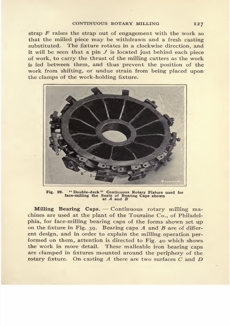
8/13/2019 Production Milling
http://slidepdf.com/reader/full/production-milling 141/296
CONTINUOUS ROTARY MILLING 12 7
strap F raises the strap out of engagement with the work so
that the milled piece may be withdrawn and a fresh casting
substituted. The fixture rotates in a clockwise direction, and
it will be seen that a pin / is located just behind each piece
of work, to carry the thrust of the milling cutters as the work
is fed between them, and thus prevent the position of the
work from shifting, or undue strain from being placed upon
the clamps of the work-holding fixture.
Fig. 39. Double-deck Continuous Rotary Fixture used for
face-milling the Seats of Bearing Caps shownat A and B
Milling Bearing Caps. Continuous rotary milling ma-
chines are used at the plant of the Touraine Co., of Philadel-
phia, for face-milling bearing caps of the forms shown set up
on the fixture in Fig. 39. Bearing caps A and B are of differ-
ent design, and in order to explain the milling operation per-
formed on them, attention is directed to Fig. 40 which shows
the work in more detail. These malleable iron bearing caps
are clamped in fixtures mounted around the periphery of the
rotary fixture. On casting A there are two surfaces C and D

8/13/2019 Production Milling
http://slidepdf.com/reader/full/production-milling 142/296
128 PRODUCTION MILLING
to be milled, while on casting B there is but a single face Eto be milled. The machine is equipped with a gang of three
cutters to provide for straddle-milling the two faces on cast-
ing A and facing off the upper surface on casting B. The sup-
porting and clamping mechanisms are of quite simple design.
Castings A are supported by two pins F, while castings B are
supported by two blocks G. Straps H which hold castings A
on the fixture must be slightly narrower than the work, to
Machinery
Fig. 40. Details of Work-holding Fixture shown in Fig. 39
allow the straddle-milling cutters to reach both surfaces C
and D. This precaution need not be observed in making
straps 7, because it is merely necessary to have the strap
engage the work at points slightly below the level of the upper
surface E. With this fixture it is only necessary to loosen the
bolts slightly that hold straps H and 7, and then the castings
may be lifted off their supporting points, F and G, respectively,
and removed from the fixture.

8/13/2019 Production Milling
http://slidepdf.com/reader/full/production-milling 143/296
CONTINUOUS ROTARY MILLING 1 29
Desirability of Continuous Rotary Milling from the Stand-
point of Production Obtained. In deciding upon the best
methods for new milling operations, and in designing auxiliary
equipments for the milling machines, decisions will in all cases
be governed by the features of the work which indicate that
preference may properly be given to some specified method
of milling. Where a plant is engaged in the quantity produc-
tion of duplicate parts, and more espeically where these parts
are of small or medium size, the continuous rotary milling
principle will often afford maximum production. Any experi-
enced mechanic who has studied the nature of the different
operations which are explained in this chapter will recognize
that in these cases very satisfactory rates of output have been
obtained. The instances which have been cited are those
where the continuous rotary milling principle has shown up
to good advantage. At the same time, the results obtained
in these cases are
byno means
exceptional. Theyare
goodenough, however, to warrant giving the continuous rotary
method careful consideration at a time when a decision is
being reached concerning the method of milling new pieces of
work which appear to be of a nature that could properly be
handled in that way.
8/13/2019 Production Milling
http://slidepdf.com/reader/full/production-milling 144/296
CHAPTER IV
PLANER MILLING PRACTICE IN AUTOMOBILE PLANTS
ALTHOUGH the term planer type generally designates
milling machines with a long table which conveys a number of
pieces of work past milling cutters carried by heads supported
on the cross-rail and housings, it is probably more accurate
to call such machines multiple-spindle milling machines.
They are especially adapted for milling large pieces of work,
and are usually designed to meet the particular requirements
for continuous use on one class of work. For instance, ma-
chines of this type are generally used in milling motor car
crankcases, cylinder blocks, cylinder heads, etc., and in almost
everycase the
millingmachine builder has been furnished
with designs of the parts and detailed information as to the
daily production required, the average depth of cut to be
taken on the different surfaces that must be milled, etc. With
these data, he is able to design a machine which has the neces-
sary number of spindles for milling the different finished sur-
faces on the work, and which is structurally adapted for the
service required.
Data concerning the number of parts per day is needed by
the milling machine designer because, if there is a large num-
ber of parts to be milled, the rate of production at once becomes
an important factor; hence it will be well worth while for
the plant investing in multiple-spindle milling machines to
obtain equipment designed to mill as many surfaces as possi-
ble simultaneously. On the other hand, if the kind of work
is limited in quantity, it may be better to perform several
independent operations on one or more machines of simpler
and less expensive construction. In the latter case, a more
complicated equipment might turn out the required produc-
tion in, say, half of a full working day, but as the machine was
130

8/13/2019 Production Milling
http://slidepdf.com/reader/full/production-milling 145/296
PLANER MILLING PRACTICE 131
especially designed for a specific class of work, it would lie
idle for 50 per cent of the time, resulting in a poor return on
a heavy investment.Features of Multiple-spindle Milling Machines. Owing
to the fact that the work-holding fixtures for multiple-spindle
milling machines are usually designed and made in the plant
of the milling machine builder, they are generally better adapted
for the work than fixtures designed by less experienced men
for other types of milling machines. In this treatise, fixtures
and methods for
milling operationsare illustrated and de-
scribed,with a brief review of the general characteristics of the
types of machines on which the work is to be done. As the
general characteristics of the standard types of milling ma-
chines are matters of general mechanical knowledge, machine
design has not been taken up in detail. In the case of fixtures
used on other types of milling machines, certain criticisms of
the fixture design are sometimes warranted. These fixtures
for use on the multiple-spindle machines, however, have been
designed by experts and are in practically every case ideal for
their work. The classes of work described in this chapter are
some of the types which are advantageously milled on multiple-
spindle machines used in automobile factories.
In operating multiple-spindle milling machines, a number
of fixtures are set up on the table, so that a string of cast-
ings may be passed between the milling cutters on the ma-
chine. Owing to the large size of the pieces to be milled, it
is generally necessary to employ a machine operator and a
helper to set up and remove the work, and these two men
follow a definite routine. It is quite a general practice to
start the machine immediately after a casting has been set
up in the fixture nearest to the milling cutters. Then the
operator and his assistant will proceed to set lip castings in
each of the other fixtures, starting with the fixture next to
the one in which the first piece was mounted. After all of
the fixtures have been loaded, one or two of the pieces carried
at the front end of the table will have passed under the cutters,
so the men immediately remove these milled pieces. Idle
8/13/2019 Production Milling
http://slidepdf.com/reader/full/production-milling 146/296
132 PRODUCTION MILLING
time of the operator is thus eliminated, because he does not
first load the fixture and then remain idle while the work is
being fed under the cutters, as is the case with some types of
single-spindle machines. About the only lost time of the
operator is that period during which the last piece of work is
being fed past the cutters.
When all of the fixtures have been emptied, the table is
quickly returned to its starting position by the power-driven
rapid traverse movement. Then the operators immediately
set
upanother
piece
of work in the first fixture and use the
rapid traverse to run this piece up almost into engagement
with the milling cutters, after which the feed movement is
engaged. The operators then start to reload the remaining
fixtures in the order which has already been explained. The
idle time of the machine also is thus cut down to a minimum,
which comprises the period required to unload the last piece
of work, return the table to the starting point, and set up the
other casting in the first fixture. Machines of this type, there-
fore, although they are usually quite expensive, are able to
attain a very high rate of production and thus pay a good
return upon the investment.
Importance of Care in Designing Work-holding Fixtures. -
Equal care must be given to the designing of the work-holding
fixtures and the machines on which they are to be used, if
maximum operating efficiency is to be obtained. On average
classes of work, it is possible to operate multiple-spindle mill-
ing machines at a feed of from 8 to 9 inches per minute, and
in working out the fixture design, this factor must be con-
stantly borne in mind. In other words, the tool designer
must first determine the amount of time it will take to feed
each piece of work past the cutters, and then work out the
designof all
adjustable supporting pointsand
clampingmech-
anisms on the fixture in such a way that the machine opera-
tor and his assistant will be able to set up a piece of work ready
for milling within the time required to feed another piece of
work past the cutters. Otherwise the setting-up time becomes
the limiting factor in determining the quantity of production.

8/13/2019 Production Milling
http://slidepdf.com/reader/full/production-milling 147/296
PLANER MILLING PRACTICE 133
Application of the Three-point Suspension Principle.-
Multiple-spindle milling machines are used for both first and
second operations on the work, and the design of fixtures will
naturally be governed by the nature of the operation to be
performed. The pieces milled on these machines are usually
of considerable size, so where the first operation is to be per-
formed with the work located on the fixture on a rough-cast
or forged surface, it is usual to employ what is known as a three-point suspension bearing. This is based upon the
familiar principle of geometry that three points determine aplane. To use a simple comparison, a three-legged stool will
stand firmly on a floor, regardless of how rough it may be;
but a four-legged stool will have one leg off the floor and be
liable to rock about, if there is any lack of uniformity in the
surface. It is exactly the same way in setting up a rough
casting for the first machining operation; with the three-point
suspension,the
castingis sure to be
firmly supported,but if
four or more supporting points are used, the casting is likely
to tilt out of place. In some cases, the cast surface of the work
may be used as a locating point, while in other instances it
may be desirable to cast bosses on the work, which come into
contact with locating points on the fixture.
The location obtained for a first operation of this character
is not extremely accurate, and in almost every case the method
of procedure is to use the finished surface milled by the first
operation as the locating point in setting up the work for sub-
sequent operations, thus bringing other finished surfaces into
an accurate relationship with the one first milled, and conse-
quently with each other. The first finished surface, therefore,
should be held within close limits of accuracy. To accomplish
this, the work must be fully supported at all points. In the
case of such pieces as cylinder blocks, special means of support
are not usually necessary, because the form of the work is such
that there is little danger of deflection resulting from the pres-
sure applied by the milling cutters. For milling crankcases
and other work of this general character, however, where the
castings are thin, and where there are flanges and arms on the

8/13/2019 Production Milling
http://slidepdf.com/reader/full/production-milling 148/296
134 PRODUCTION MILLING
work, which have considerable overhang, all such unsupported
members must be held in a way which will adequately resist
the cutting pressure.
Compensation for Variations in Size of Forgings and Cast-
ings. As the work is being located from a cast or forged
surface, and as there may be as much as f inch variation in a
casting, or -^ inch variation in a forging produced under the
best possible conditions, fixed supports cannot be provided on
the fixture to come into engagement with the work. The three
pointsof the
three-point suspension bearingare
fixed,but all
other supporting members must be made adjustable, so that
after the casting is dropped into place on the three fixed
points, these adjustable points can be brought up into en-
gagement with the work and then clamped in this position.
Commonly used forms of construction for this purpose are to
have either plungers supported by compression springs, or
plungers which rest upon a sliding tapered surface' at their
lower end, with a screw for the purpose of manipulation.
Where either of these designs is used, the plunger is brought
up into engagement with the section of the work which it
is to support and then firmly clamped in position by a screw.
After the first operation has been performed, the milled
surface may be used as a locating point for subsequent oper-
ations. If this surface has been milled without springing
the work, there will be a perfectly plane surface to use for
locating the piece ready for the next operation; consequently,
any required number of points may be provided on the fixture
to afford the necessary support. It is usually important to
provide for locating the work in certain other directions also,
depending on the form of the pieces being milled.
Cutting Speeds for Planer Milling Machines. Sixty feet
per minute probably represents an approximate average of the
speeds at which cutters are commonly driven on planer-type
milling machines. If the cutters are properly designed, and
the necessary precautions taken to provide for the dissipation
of heat generated in cutting the metal, it will be found that
this figure can be increased. The contention is made that the
8/13/2019 Production Milling
http://slidepdf.com/reader/full/production-milling 149/296
PLANER MILLING PRACTICE 135
chips usually produced by cutters on machines of this type
are fine, and that each edge of the tool is usually in action for
not more than 5 per cent of the running time; that is to say,
each edge on the cutter is working for 5 per cent of a revolu-
tion and has the remaining 95 per cent of the revolution dur-
ing which the coolant can absorb heat. With very high speeds
the arbors on which the cutters are mounted should be of
ample size and plenty of power should be provided for driving
the milling machine. Most of the planer-type milling ma-
chines being built today are provided with ample power and
strength to enable the best types of high-speed steel milling
cutters to be driven to their maximum productive capacity.
Users of these machines, however, sometimes overlook the
necessity of mounting milling cutters upon an arbor of suffi-
cient size to withstand the severe torsional and bending stresses
to which it is subjected. Generally, the capacity of the cutters
limits the rate of production obtained by planer-type milling
machines; but if an arbor of insufficient size is used, this
carelessness on the part of the tool designer places a serious
handicap upon the amount of work which the machine can
turn out in a specified period of operation.
Beaman & Smith Planer-type Milling Machines. A multi-
ple-spindle or planer type of milling machine built by the
Beaman & Smith Co., possesses the usualfeatures of an
equip-ment of this kind and also provides for eliminating the idle
time of the machine which ordinarily occurs while the operator
is removing the work from the last one or two fixtures, return-
ing the table to the starting position, and setting up a casting
in the first fixture on the table ready for starting the next cut.
This result is secured through having the table made in sec-
tions of just sufficient size to allow a single work-holding fix-
ture to be mounted on each section of the table. Thus, each
fixture may be unloaded after the work has passed under the
milling cutters and the table is then picked up by a trolley
hoist and carried around to the opposite end of the milling
machine bed, where it is again lowered into place on the ways.
Where a planer-type milling machine is designed and used
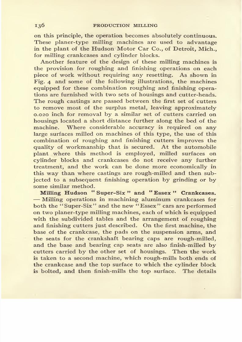
8/13/2019 Production Milling
http://slidepdf.com/reader/full/production-milling 150/296
136 PRODUCTION MILLING
on this principle, the operation becomes absolutely continuous.
These planer-type milling machines are used to advantage
in the plant of the Hudson Motor Car Co., of Detroit, Mich.,
for milling crankcases and cylinder blocks.
Another feature of the design of these milling machines is
the provision for roughing and finishing operations on each
piece of work without requiring any resetting. As shown in
Fig. 4 and some of the following illustrations, the machines
equipped for these combination roughing and finishing opera-
tions are furnished with two sets of housings and cutter-heads.
The rough castings are passed between the first set of cutters
to remove most of the surplus metal, leaving approximately
0.020 inch for removal by a similar set of cutters carried on
housings located a short distance further along the bed of the
machine. Where considerable accuracy is required on any
large surfaces milled on machines of this type, the use of this
combination ofroughing
andfinishing
cuttersimproves
the
quality of workmanship that is secured. At the automobile
plant where this method is employed, milled surfaces on
cylinder blocks and crankcases do not receive any further
treatment, and the work can be done more economically in
this way than where castings are rough-milled and then sub-
jected to a subsequent finishing operation by grinding or by
some similar method.
Milling Hudson Super-Six and Essex Crankcases.
Milling operations in machining aluminum crankcases for
both the Super-Six and the new Essex cars are performed
on two planer-type milling machines, each of which is equipped
with the subdivided tables and the arrangement of roughing
and finishing cutters just described. On the first machine, the
base of the crankcase, the pads on the suspension arms, and
the seats for the crankshaft bearing caps are rough-milled,
and the base and bearing cap seats are also finish-milled by
cutters carried by the other set of housings. Then the work
is taken to a second machine, which rough-mills both ends of
the crankcase and the top surface to which the cylinder block
is bolted, and then finish-mills the top surface. The details

8/13/2019 Production Milling
http://slidepdf.com/reader/full/production-milling 151/296
PLANER MILLING PRACTICE 137
of the work-holding fixtures and the routine followed in han-
dling the work will next be described.
Milling Pads on Suspension Arms of Crankcase. Figure i
shows that the large inserted-tooth cutters A and B provide
for milling the pads on the suspension arms at each side of the
Fig. 1. View of Two Table Sections and Roughing Cutters onMachine milling Automobile Crankcases
crankcase, by means of which the motor is supported on the
chassis; and that the two smaller cutters C and D mill seats
for the crankshaft bearing caps. The base of the crankcase is
also milled by two other cutters which are not shown but which
are mounted on vertical spindles carried in bearings E and F.
After each crankcase passes under this first set of six cutters,

8/13/2019 Production Milling
http://slidepdf.com/reader/full/production-milling 152/296
138 PRODUCTION MILLING
the table which carries the work-holding fixture is traversed
along the bed of the machine to feed the work under a second
set of four cutters carried on the other housings. These finish-
mill the crankcase base and crankshaft bearing cap seats, the
roughing and finishing being performed without interruption.
Fig. 2. Close View of Work-holding Fixture of Type used to
hold Crankcases on Machine shown in Fig. 1
After these milling operations have been completed, the
casting is removed from the work-holding fixture, and four
hooks, located at the ends of chains carried by a trolley hoist,
are passed through rings at the corners of the table. The table
is then lifted off the bed of the milling machine and carried
around on a crescent-shaped trolley rail, which brings it back

8/13/2019 Production Milling
http://slidepdf.com/reader/full/production-milling 153/296

8/13/2019 Production Milling
http://slidepdf.com/reader/full/production-milling 154/296
140 PRODUCTION MILLING
means of screws L, they not only force the plungers up into
engagement with the work, but also hold them rigidly in
that position, thus affording adequate support for the pressureexerted by the milling cutters. In addition to plungers K,
there are three spring plungers M which are held in contact
with the work when it is placed in the fixture by means of
compression springs located beneath these plungers. The
plungers are firmly located against the work and then clamped
in this position by binding screws N.
Gaging Castingsbefore
Starting Machining Operations.Some foundries make it a rule not to allow credit for any
Fig. 3. Inspection Fixture used for checking up Crankcase
Castings to see that Sufficient Metal is provided to clean
up all Machined Surfaces
defective castings upon which machining operations have been
started;but whether or not this is a rule of the foundry which
delivers castings to a machine shop, it is a good practice for
the shop to inspect all of its castings before work is started.
It is, of course, desirable to obtain credit from the foundry for
any castings of such poor quality that they cannot be success-
fully machined, but the saving effected through getting such
credit for defective castings often represents but a small per-
centage of the actual loss which would be suffered by the
manufacturer if he proceeded with the machining operations
until the work reached a point where the defect in the casting
made it impossible to clean up some surface.
Recognizing the importance of this point, the Hudson
Motor Car Co. uses a crankcase casting inspection fixture as

8/13/2019 Production Milling
http://slidepdf.com/reader/full/production-milling 155/296
PLANER MILLING PRACTICE 141
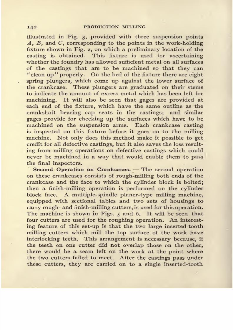
8/13/2019 Production Milling
http://slidepdf.com/reader/full/production-milling 156/296
142 PRODUCTION MILLING
illustrated in Fig. 3, provided with three suspension points
A, Byand
C, correspondingto the
pointsin the
work-holdingfixture shown in Fig. 2, on which a preliminary location of the
casting is obtained. This fixture is used for ascertaining
whether the foundry has allowed sufficient metal on all surfaces
of the castings that are to be machined so that they can
clean up properly. On the bed of the fixture there are eight
spring plungers, which come up against the lower surface of
the crankcase. These plungers are graduated on their stems
to indicate the amount of excess metal which has been left for
machining. It will also be seen that gages are provided at
each end of the fixture, which have the same outline as the
crankshaft bearing cap seats in the castings; and similar
gages provide for checking up the surfaces which have to be
machined on the suspension arms. Each crankcase casting
is inspected on this fixture before it goes on to the milling
machine. Not only does this method make it possible to get
credit for all defective castings, but it also saves the loss result-
ing from milling operations on defective castings which could
never be machined in a way that would enable them to pass
the final inspectors.
Second Operation on Crankcases. The second operation
on these crankcases consists of rough-milling both ends of the
crankcase and the face to which the cylinder block is bolted;then a finish-milling operation is performed on the cylinder
block face. A multiple-spindle planer-type milling machine,
equipped with sectional tables and two sets of housings to
carry rough- and finish-milling cutters, is used for this operation.
The machine is shown in Figs. 5 and 6. It will be seen that
four cutters are used for the roughing operation. An interest-
ing feature of this set-up is that the two large inserted-tooth
milling cutters which mill the top surface of the work have
interlocking teeth. This arrangement is necessary because, if
the teeth on one cutter did not overlap those on the other,
there would be a seam left on the work at the point where
the two cutters failed to meet. After the castings pass under
these cutters, they are carried on to a single inserted-tooth

8/13/2019 Production Milling
http://slidepdf.com/reader/full/production-milling 157/296

8/13/2019 Production Milling
http://slidepdf.com/reader/full/production-milling 158/296
144 PRODUCTION MILLING
milling cutter of sufficient size to extend completely across
the surface to which the cylinder block is bolted. This large
cutter can be clearly seen in Fig. 6, and it is used in place of
the two interlocking mills, because greater accuracy can be
obtained in finishing the cylinder block seat in this way.
The finish-milling operation is not performed on the ends of
the crankcase.
Milling Different Crankcases on One Fixture. In connec-
tion with the work-holding fixtures used on this machine, one
especially interesting feature of tool design is that the same
fixtures may be utilized for milling crankcases for either the
Super-Six or the
Essex car. This saves the cost of an
additional set of fixtures; furthermore, a machine may be
converted from the milling operations on one type of crank-
case to the other with less loss of time than would be required
if it were necessary to remove one set of fixtures and substitute
others in their places.
It will be recalled that the usual practice in designing work-
holding fixtures for the performance of second milling opera-
tions on large-sized pieces of work is to use a previously milled
surface of the work as a locating point for subsequent opera-
tions. This is the method followed in designing the work-
holding fixtures shown in Figs. 5 and 6; and where this method
maybe
employed,it is
usually possibleto make a fixture of
quite simple design. There are fixed pads on the bed of each
fixture, which engage the milled lower surface of the crank-
case, and endwise location of the work is obtained by means
of a V-block that fits over a projection on the side of each
casting. In order to have the ends of the cases milled square
with the crankshaft bearings, it is also important to locate
the work from these bearings. This is done by using as locat-
ing points the seats which were milled during the preceding
operation to receive the crankshaft bearing caps. These
milled seats drop over blocks on the fixtures, and the work is
now located in the desired position. To clamp it down ready
for milling, it is merely necessary to tighten up four straps
on the 'flange running around the lower faces of the crankcase.
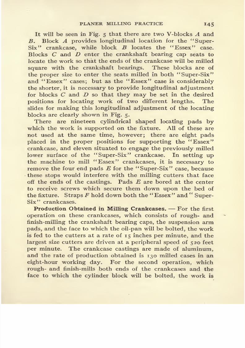
8/13/2019 Production Milling
http://slidepdf.com/reader/full/production-milling 159/296
PLANER MILLING PRACTICE 145
It will be seen in Fig. 5 that there are two V-blocks A and
B. Block A provides longitudinal location for the Super-
Six crankcase, while block B locates the Essex case.
Blocks C and D enter the crankshaft bearing cap seats to
locate the work so that the ends of the crankcase will be milled
square with the crankshaft bearings. These blocks are of
the proper size to enter the seats milled in both Super-Six
and Essex cases; but as the
Essex case is considerably
the shorter, it is necessary to provide longitudinal adjustment
for blocks C and Dso
that they may beset in
the desired
positions for locating work of two different lengths. The
slides for making this longitudinal adjustment of the locating
blocks are clearly shown in Fig. 5.
There are nineteen cylindrical shaped locating pads by
which the work is supported on the fixture. All of these are
not used at the same time, however; there are eight pads
placed in the proper positions for supporting the Essex
crankcase, and eleven situated to engage the previously milled
lower surface of the Super-Six crankcase. In setting up
the machine to mill Essex crankcases, it is necessary to
remove the four end pads E for the Super-Six case, because
these stops would interfere with the milling cutters that face
off the ends of the castings. Pads E are bored at the center
to receive screws which secure them down upon the bed of
the fixture. Straps F hold down both the Essex and Super-
Six crankcases.
Production Obtained in Milling Crankcases. For the first
operation on these crankcases, which consists of rough- and
finish-milling the crankshaft bearing caps, the suspension arm
pads, and the face to which the oil-pan will be bolted, the work
is fed to the cutters at a rate of 15 inches per minute, and the
largest size cutters are driven at a peripheral speed of 520 feet
per minute. The crankcase castings are made of aluminum,
and the rate of production obtained is 130 milled cases in an
eight-hour working day. For the second operation, which
rough- and finish-mills both ends of the crankcases and the
face to which the cylinder block will be bolted, the work is
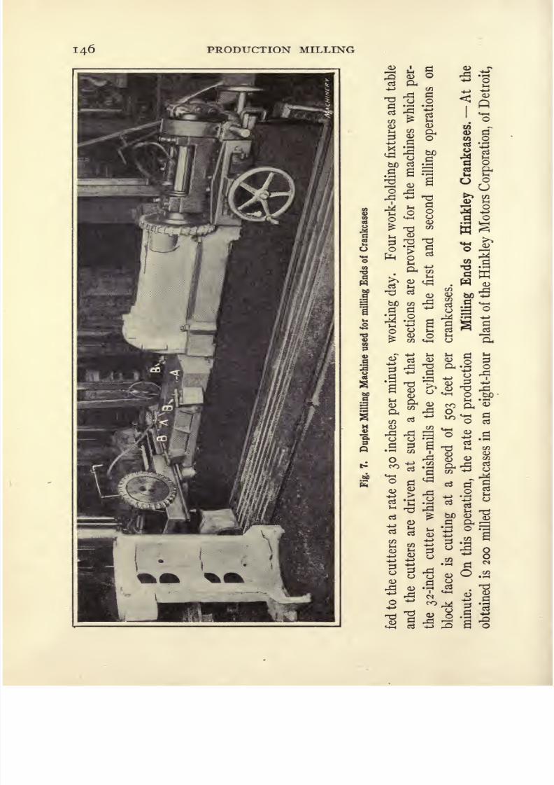
8/13/2019 Production Milling
http://slidepdf.com/reader/full/production-milling 160/296
146 PRODUCTION MILLING

8/13/2019 Production Milling
http://slidepdf.com/reader/full/production-milling 161/296
PLANER MILLING PRACTICE 147
Mich., use is made of a duplex milling machine of the type
made by the Garvin Machine Co., for milling one end of alumi-
numcrankcases for motor truck
engines.The
opposite end ofthese cases has already been machined, and the face on which
the oil-pan will be bolted has had two dowel-pin holes drilled
in its flange. These holes are used as the locating points in
setting work up on the milling machine to have the end of
the case milled exactly at right angles to the crankshaft bear-
ings. For this purpose, two dowel-pins A, Fig. 7, are placed
in the table of the machine at each end, so that the crankcases
may be dropped over these pins, after which they are held down
by means of four straps B, which engage the flange running
around the work. This operation is performed with milling
cutters 1 6 inches in diameter which run at a speed of 135 feet
per minute, and with a feed of 10 inches per minute. Two
castings are set up on the machine at a time, each of which
is milled at only one end. The rate of production is thirty
crankcases per hour.
Simultaneous Performance of First and Second Operations
on Crankcases. In the plant of the Studebaker Corpora-
tion, in Detroit, Mich., a work-holding fixture is used which
provides for simultaneously performing the first and second
milling operations on cast-iron crankcases which are held at
opposite sides of a vertical work-holding fixture. Figures 8
and 9 show that the fixture consists essentially of a plate sup-
ported edgewise on the table of a multiple-spindle milling
machine and furnished with the necessary clamping mechan-
ism to provide for operating on a crankcase held at either side
of the fixture. The first operation consists of milling the face
of the crankcase to which the cylinder block will be bolted;
then the crankcase is removed from the fixture, and after
beingturned
over,it is
againset
upat the
oppositeside for
milling the oil-pan face of the crankcase. A sidehead is mounted
on each housing of the machine to provide for simultaneously
taking these two cuts on the work.
For the first operation on the crankcases, the work, held in
the fixture shown in Fig. 8, is located from the oil-pan face of

8/13/2019 Production Milling
http://slidepdf.com/reader/full/production-milling 162/296
148 PRODUCTION MILLING
Fig. 8. Fixture used for simultaneously milling Opposite Sides of Cast-iron Crankcases
Fig. 9. Opposite Side of Fixture shown in Fig. 8

8/13/2019 Production Milling
http://slidepdf.com/reader/full/production-milling 163/296
PLANER MILLING PRACTICE 149
the crankcase. In locating the rough castings in a fixture, it
is usual to employ a three-point suspension bearing, but in
this case, such a design did not appear to be practical. Owing
to the fact that four corners of the work are used for location,
it is necessary for the machine operator first to check up the
accuracy of his castings with a gage and, if necessary, grind
down one corner with a portable electric grinding machine
until the work will rest against the surface plate without
rocking.
In setting up a casting on the fixture shown in Fig. 8, the
lower edge of the crankcase is set on two pins A, after which
the case is pushed back against the fixture so that the four
corners may be supported by pads B. To provide for carrying
the end thrust of the milling cutters, the inside of the front
end of each casting rests against two pins C, and three straps
and a clamping screw D hold the work back against the four
supporting pads B. It takes approximately one minute to
set up each casting in its fixture for the first operation, and
the work is fed to the milling cutters at the rate of 4 inches per
minute. The cutters are 16 inches in diameter and run at a
speed of 1 8 revolutions per minute, which corresponds to a
cutting speed of 75.5 feet per minute. Four castings are set
up at each side of the fixtures for each traverse of the table.
The first
operation
is
performed
on seven and one-half crank-
cases per hour.
Each casting carried by the fixture shown in Fig. 8 is fed
past an inserted-tooth milling cutter which faces off the
cylinder block face of the crankcase, after which the casting
is removed from the fixture and carried around to the oppo-
site side of the machine. After the work-holding fixtures have
been unloaded at that side, the partially milled castings are
set up, with the milled cylinder block seat as a locating point.
Six fixed locating pads A, Fig. 9, engage the milled face of
the work. The casting is slipped over two pins B which hold
it up in the desired position until the clamps are tightened,
and a third pin C engages the inside of the casting at the for-
ward end to support the thrust of the milling cutters. Each

8/13/2019 Production Milling
http://slidepdf.com/reader/full/production-milling 164/296
150 PRODUCTION MILLING
of the suspension arms of the crankcase must be supported in
order to prevent distortion resulting from the pressure exerted
by the milling cutters. For this purpose three spring plungers
D are used, which come up into engagement with the work at
the time that it is placed in the fixture. Each of these plungers
is then clamped in the desired position by means of a screw
E}the screw for bolting the pin at the front end of the fixture
not being shown in the illustration. With the casting set up
and located in this way, it is clamped back on the fixture by
two straps F which are made semi-cylindrical in form to fit
the crankshaft bearings. These straps are furnished with
V-shaped slots and are dropped over the bolts, instead of
having the bolts enter holes drilled through the straps, the
purpose being to enable the straps to be lifted off the bolts
after the nuts have been slightly loosened. This saves a large
part of the time which would otherwise be required to screw
the nutsall
the way off the bolts in order to remove the strapsand allow the castings to be lifted off the fixtures. The work
is done at a cutting speed of 75.5 feet per minute, with a feed
of 4 inches per minute, and the rate of production is seven
and one-half completely milled crankcases per hour.
Work-holding Fixture for First Operation on Cylinder
Blocks. Cylinder blocks of the Super-Six and Essex
motors are milled on Beaman & Smith multiple-spindle mill-
ing machines. Two machines are used for this work. The
first step is to set up three pairs of cylinder block castings on
a machine equipped with a single table and a string of fixtures.
This machine has two side-heads mounted on the housings,
each of which carries an inserted-tooth milling cutter of suffi-
cient size to face off the exhaust manifold seats and the valve
chamber cover. Figure 10 shows that each of the three fix-
tures will hold two cylinder blocks, so that this operation maybe performed simultaneously on six castings by cutters carried
on the opposed spindles of the side-heads. For this milling
operation, each cylinder block casting is located against three
fixed points A, B, and C, on the vertical face of the fixture.
To assist in supporting the work, there are eight spring plungers

8/13/2019 Production Milling
http://slidepdf.com/reader/full/production-milling 165/296
Fig. 10. Work-holding Fixture for First Operation on Hudson Cylinder Blocks
Fig. 11. 'Work-holding Fixture for Second Operation on Hudson Cylinder Blocks
10 M

8/13/2019 Production Milling
http://slidepdf.com/reader/full/production-milling 166/296
152 PRODUCTION MILLING
D equipped with locking screws which hold them rigidly in
place after engaging the casting; and the final clamping is
accomplished by two straps E provided with handwheels asillustrated. These straps have compression springs beneath
them, so that they are raised out of contact with the work
when the handwheels are unscrewed.
Before straps E are tightened, a yoke F is placed over the
two castings at opposite sides of the vertical plate of the fix-
ture, and the screw of this yoke is tightened to draw both cast-
ings firmly back against their fixed locating points, A, B, and
C. While the yoke is still over the castings, the screws which
clamp spring plungers D are tightened and the handwheels
that clamp straps E are also turned down, thus accurately
locating the two castings at opposite sides of the fixture.
After they have been tightened up, the yoke F may be re-
moved without any danger of the work springing out of place.
When milling cylinder blocks for the Essex motor, the
surface to be milled is approximately 19 inches long by pj
inches wide. Owing to the hardness of the metal, the rate of
feed employed is rather lower than that called for by average
practice, namely, 6 inches per minute; and the cutting speed
is 63 feet per minute. The production obtained for an eight-
hour working day is 130 cylinder blocks. On the Super-Six
blocks, the surface to be milled is 29 inches long by 9 inches
wide, and on this job, 70 cylinder blocks are milled in an
eight-hour working day.
Work-holding Fixture for Second Operation on Cylinder
Blocks. Following the usual practice in milling large-sized
pieces of work, the surface machined during the first operation
on the cylinder blocks is made the locating point for the second
operation. A close view of one work-holding fixture and of
theroughing
cutters on the machine used for this second
operation is shown in Fig. n; and Fig. 12 illustrates a view
of the complete machine in order to show how each section of
the divided table is brought back to the starting end of the
machine ready to be loaded for the next operation. On this
machine, rough- and finish-milling operations are performed

8/13/2019 Production Milling
http://slidepdf.com/reader/full/production-milling 167/296
PLANER MILLING PRACTICE 153
II

8/13/2019 Production Milling
http://slidepdf.com/reader/full/production-milling 168/296

8/13/2019 Production Milling
http://slidepdf.com/reader/full/production-milling 169/296
PLANER MILLING PRACTICE 155
as each table is brought back to the starting point and lowered
to the bed, a cylinder block casting is taken from the pile and
lowered into the fixture. The best method would, of course,
be to have the castings taken directly off the first-operation
machine and carried over to the second machine, synchroniz-
ing the speed of the two machines so that their production
would be equal. This has been found impracticable in the
present case, however, because the first machine produces
much more rapidly than the second one; hence the necessity
of accumulating a reserve of castings around the machine for
the second operation.
This machine is equipped with four Work-holding fixtures
and two sets of three milling heads, one head of each set being
mounted on the cross-rail and one on each of the housings.
Cutters carried by these heads rough-mill the faces to which
the cylinder head, the crankcase, and the intake manifold
are bolted. There is a similar set of cutters mounted on a
second housing for the finish-milling operations on the same
faces of the work. The design of the work-holding fixtures
on this machine is explained by Fig. n, where it will be seen
that there are three finished faces A to support the work from
the surface of the exhaust manifold seat and valve chamber
seat, which were milled during the first operation. This
holds the cylinder block in a horizontal position; but as the
top and bottom surfaces of the block are to be milled, it is
important to have the casting so located that these surfaces
will be accurately aligned with other faces of the work. This
location is accomplished by means of two blocks B which
engage fixed points cast in the valve chamber of each cylinder
block for that purpose. The casting is held back against
these blocks B by hooks C which engage the casting, and it
is drawn to the desired location
byscrews
manipulated fromthe opposite side of the fixture. The casting also rests against
the head of screw D which supports the end thrust. After
being located in this way, the casting is clamped down in the
fixture by two straps E. This operation is accomplished at
a speed of 65 feet per minute with a feed of n inches per

8/13/2019 Production Milling
http://slidepdf.com/reader/full/production-milling 170/296

8/13/2019 Production Milling
http://slidepdf.com/reader/full/production-milling 171/296
Fig.13.
MillingMachine with
InterlockingCutters to
produce Sharp Edges
Fig. 14. Opposite Side of Multiple-spindle Milling Machine shown in Fig. 13
IS7
8/13/2019 Production Milling
http://slidepdf.com/reader/full/production-milling 172/296
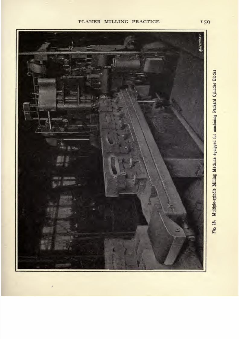
8/13/2019 Production Milling
http://slidepdf.com/reader/full/production-milling 173/296
PLANER MILLING PRACTICE 159
1
S

8/13/2019 Production Milling
http://slidepdf.com/reader/full/production-milling 174/296
l6o PRODUCTION MILLING
along which the castings run to a multiple-spindle milling
machine, shown in Fig. 15, on which the remaining milling
operationsare
performed.This machine is
equippedwith
four milling cutters to mill the seats for the valve chamber
cover, the intake manifold, the cylinder block cover, and the
exhaust manifold simultaneously. The equipment of this
machine is not unusual, with the possible exception of the
fact that a two-spindle side-head is mounted on one of the
housings for driving two cutters used for milling the valve
cover seat and the intake manifold seat at different levels.
Fig. 16. Work-holding Fixture and Cutters used for machiningPackard Cylinder Blocks on Multiple-spindle Milling Machine
A marked departure from the usual practice has been made
in designing the work-holding fixtures used on this machine,
but this would naturally be expected as the cylinder blocks
delivered to the machine have been bored and milled on the
crankcase face, and all of the holes have been drilled in this
face of thework,
while in the case of othercylinder
block
milling fixtures which have been described, the work is set
up on the machine in the condition in which the castings are
delivered from the foundry. At the time holes are being
drilled in the crankcase face of these cylinder blocks, two
dowel-pin holes are drilled, which will be utilized in the engine

8/13/2019 Production Milling
http://slidepdf.com/reader/full/production-milling 175/296
PLANER MILLING PRACTICE l6l
assembling department for lining up bolt holes in the cylinder
block and crankcase. Locating pins A on the fixture enter
these dowel holes when setting up the work on the milling
machine shown in Figs. 16 and 17. The previously milled
surface on the work is used to support it for subsequent mill-
ing operations, and for this purpose nine finished pads B are
provided.
The casting is held down at one side by two bolts C, which
pass through holes drilled in the flange of the crankcase face;
and at the opposite side there are three straps D which bear
Fig. 17. View from Opposite Side of Multiple-spindle MillingMachine shown in Fig. 16 showing Further Details of
Cutters and Fixtures
upon the upper surface of the same flange. All of these clamp-
ing members are located at the base of the work, and it is
necessary also to steady the work to prevent pressure of the
cutters applied near the top of the castings from setting up
chatter and vibration. This is done by two split chucks Ewhich fit into the bored cylinders at opposite ends of the block.
By tightening the nuts located at the top of chucks E, tapered
blocks inside of these chucks are drawn downward, thus
expanding the chucks and causing them to obtain a firm grip
on the work. The fixtures can be loaded with very little loss

8/13/2019 Production Milling
http://slidepdf.com/reader/full/production-milling 176/296
162 PRODUCTION MILLING
of time. The work is fed to the milling cutters at a rate of 8
inches per minute and the cutters are geared to give a cutting
speed
of 60 feet
perminute. The rate of
productionobtained
is from 45 to 50 cylinder blocks in a nine-hour working day.
Four cylinder blocks are set up on the machine for each traverse
of the table.
Practice of Studebaker Corporation in Milling Cylinder
Blocks. Ingersoll multiple-spindle milling machines are
Fig. 18. Close View of Work-holding Fixture and Cutters on
Multiple-spindle Milling Machine for milling Stude-baker Cylinder Blocks
used by the Studebaker Corporation for milling the surfaces
of cylinder blocks on which the manifold, crankcase and
cylinder head are mounted. Figures 18 and 19 explain the
design of the work-holding fixtures used on these machines.
The fixtures are shown fromopposite
sides in order to illus-
trate fully the locating and clamping mechanisms, and the
arrangement of cutters on each of the milling heads. The
work is set up in these fixtures with the cylinders lying in a
horizontal position. To supplement the way in which the
casting is held by the three suspension points A on the fixture,

8/13/2019 Production Milling
http://slidepdf.com/reader/full/production-milling 177/296
PLANER MILLING PRACTICE 163
four spring plungers B come up into engagement with the
work and are then locked in that position by the usual arrange-
ment of binding screws. Oneof the
buttons A engages theunder side of the water jacket, and there are a pair of buttons
A at each end of the fixture, which straddle the outside of the
cylinder wall. Sidewise location of the castings is accom-
plished by having the flange of the casting come into engage-
ment at each end of the work with fixed stops C. The end of
screw D projects inward through the body of the fixture,
Fig. 19. Opposite Side of Machine illustrated in Fig. 18 showingFurther Details of Work-holding Fixture Design and
Arrangement of Cutters
engaging the work and supporting the end thrust of the cut-
ters. Bar clamps the castings down in the fixture. This
bar is pivoted at F and formed in such a way that a narrow
extension at the free end of the bar enters a slot milled in the
upright of the fixture body so that it may be held down by a
sliding pin G. When bar E has been lowered and locked in
place, two screws H are tightened down on the cylinder block
casting, thus holding it securely in the desired position in the
fixture. The castings are fed to the milling cutters at the rate
8/13/2019 Production Milling
http://slidepdf.com/reader/full/production-milling 178/296
164 PRODUCTION MILLING
of approximately 8 inches per minute, and the cutters are
driven at a cutting speed of 6i| feet per minute. Three cast-
ings are set up at a time and the rate of production obtainedis six cylinder blocks per hour. One man can operate two
machines as it takes only two minutes and fifteen seconds to
load a fixture. The machine is started after loading the first
one of the string of fixtures on the table.
Practice of Continental Motors Corporation in Milling
Cylinder Blocks. It is always interesting to compare the
methods used
by
different tool designers in equipping ma-
chines for the performance of the same operation, and such
an opportunity is now presented for contrasting the practice
of the Continental Motors Corporation, of Detroit, Mich.,
in milling cylinder blocks as shown in Fig. 20, with that of
the Hinkley Motors Corporation, shown in Figs. 13 and 14.
In both cases, the machine is required to mill the faces to
which the crankcase, valve chamber cover plate, manifold, and
cylinder head are bolted. It will be recalled that the Hinkley
tool designers adopted the use of interlocking milling cutters
in order to produce square edges on the work; but for the
same operation on Continental cylinder blocks, the tool de-
signers decided upon a four-spindle milling machine, shown
in Fig. 20. Two large inserted-tooth cutters, carried by the
side-heads, mill the top and bottom faces of the cylinder block
according to the usual practice. But for miling the seats on
which the valve chamber cover plate and the manifold are
mounted, two vertical spindles are employed, the spindle
which carries the small cutter to mill the manifold face being
offset sufficiently so that its teeth do not interfere with the
teeth on eitjier of the cutters carried by the vertical or the
horizontal spindle. The cutters carried by the two vertical
spindles are also set to mill the manifold face and valve cham-ber cover plate face at different levels, instead of having two
cutters mounted on the vertical spindle, as shown in Figs. 13
and 14. With this arrangement, the cutters that mill the
cylinder head face and manifold face can each overhang the
work sufficiently to mill a square edge at the intersection of

8/13/2019 Production Milling
http://slidepdf.com/reader/full/production-milling 179/296
Fig. 20. Design of Fixture and Arrangement of Cutters used on Multiple-spindle
Milling Machine for milling Continental Cylinder Blocks
Fig. 21. Multiple-spindle Milling Machine equipped with an Indexing Table
for milling Hudson Cylinder Heads 165
8/13/2019 Production Milling
http://slidepdf.com/reader/full/production-milling 180/296
166 PRODUCTION MILLING
these surfaces. The inserted-tooth cutter which mills the
crankcase face is made of considerably larger diameter than
the width of the face to bemilled.
With this
arrangement,the cutter that mills the valve chamber cover plate face pro-
jects beyond the edge of the work into the space created by
having the edges of the blades of the cutter, which is carried
by the horizontal spindle, project out from the body of the
cutter in the usual way.
The work is placed in the fixture with the cylinders in a
horizontal position and with the valve chamber at the top.
The casting is supported by three fixed pads A . Two capstan-
head screws operate hooks B which engage the flange on the
work and provide for pulling the casting forward against two
sidewise locating stops C. At the opposite side of the fixture
there are two screws that operate tapered plugs located be-
neath the adjustable pads D, to afford additional support for
the work. The screws draw these pads D up into contact with
the work, locating them in the required positions. Each cast-
ing is held down in the fixture by means of two bevel-ended
straps E at one side of the fixture and by two straps F at the
opposite side, which are provided with cylindrical shaped ends
that enter the core support holes in the casting. Seven past-
ings are set up on the machine at a time, and the cutters are
driven at a speed of 76 feet per minute, with a rate of feed of
8 inches per minute. The rate of production is n cylinderblocks per hour. Two men load and unload the fixtures on
this machine.
Milling Continental Cylinder Heads. In machining Con-
tinental cylinder heads for automobile engines, it is necessary
to mill the bottom face which is bolted to the cylinder block
and also face off the bosses at the top surface of the head. For
these two operations a four-spindle milling machine is used,
equipped with fixtures of the type shown in Fig. 22. Two
castings are set up on the top of this fixture for facing off the
bosses; then the two pieces of work are turned over and bolted
to the sides of the same fixture ready for a second operation that
mills the lower surface of the head which engages the milled
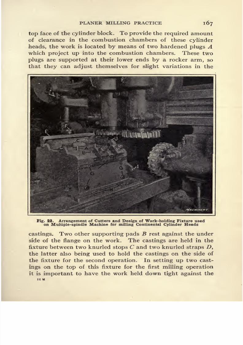
8/13/2019 Production Milling
http://slidepdf.com/reader/full/production-milling 181/296
PLANER MILLING PRACTICE I67
top face of the cylinder block. To provide the required amount
of clearance in the combustion chambers of these cylinder
heads, the work is located by means of two hardened plugs Awhich project up into the combustion chambers. These two
plugs are supported at their lower ends by a rocker arm, so
that they can adjust themselves for slight variations in the
Fig. 22. Arrangement of Cutters and Design of Work-holding Fixture usedon Multiple-spindle Machine for milling Continental Cylinder Heads
castings. Two other supporting pads B rest against the under
side of the flange on the work. The castings are held in the
fixture between two knurled stops C and two knurled straps D,
the latter also being used to hold the castings on the side of
the fixture for the second operation. In setting up two cast-
ings on the top of this fixture for the first milling operation
it is important to have the work held down tight against the

8/13/2019 Production Milling
http://slidepdf.com/reader/full/production-milling 182/296
168 PRODUCTION MILLING
locating points of the fixture. This is done by yokes E which
have a hook at each end; these hooks grip pins provided in the
fixture for that purpose. Then capstan screw F is tightenedon the work to force it firmly against the locating points of
the fixture. When the casting has been located in this way,
straps D are tightened; yokes E may then be removed with-
out springing the work out of place.
After the first operation has been performed on castings
mounted in the two stations at the top of the fixture, they
are set up at the sides of the fixture, being located from the
milled faces of the bosses on the castings, which come into
engagement with five fixed stops G. Straps D secure the work
at the side of the fixture, these straps forcing the casting down
against knurled stops H. Each fixture, as it passes under the
milling cutters, is loaded with four cylinder head castings,
two of which have the first operation performed on them while
the second operation is being performed on the other two
castings. Consequently, two cylinder heads are finished as
each fixture passes under the cutter. There are two setting
points / and / that are used with a feeling gage ^ inch in
thickness for locating the cutters at the time the machine is
being set up. The cutting speed is 102.6 feet per minute, with
a feed of 4 inches per minute. The rate of production for both
operations on the cylinder heads is 12 per hour. Two men
are employed to load and unload the fixtures.
Milling Hudson Super-Six
Cylinder Heads. For mill-
ing the water-jacketed head of the Super-Six motor, it is
necessary to take one facing cut over the top of the head, and
a roughing and finishing cut over the surface which comes into
engagement with the milled top of the cylinder block. For
these operations, a special three-spindle milling machine is
used which is
equippedwith an
indexingtable fitted with six
work-holding fixtures. This equipment, which is shown in
Fig. 21, has the advantage of allowing milling operations to
be performed on three castings carried in the fixtures at one
end of the table while the operator is removing milled cylinder
heads and substituting other castings in the fixtures at the

8/13/2019 Production Milling
http://slidepdf.com/reader/full/production-milling 183/296
PLANER MILLING PRACTICE 169
opposite end of the table. Then it is merely necessary to
withdraw the locking pin and rotate the table through 180
degreesto
bringthe next
castingsinto the
operating position.With an equipment of this kind, there is little idle time of
either the machine or its operator.
Lever E provides for withdrawing the locking bolt when it
is required to index the table to bring the next set of castings
into the operating position. The first operation consists of
milling the top face of one cylinder head, and there are two
castings set up on the table for this operation, one of which is
shown under the left-hand spindle of the machine, while the
other casting will be set up diagonally opposite, that is, at the
right-hand end of the front row of fixtures. After this opera-
tion has been performed on the top of the casting, it is removed
from the first fixture, turned over and set up in the middle
fixture of the same row, so that at the next traverse under the
cutters it is ready to have the roughing cut taken on its under
surface that comes into contact with the top of the cylinder
block. When the table is again indexed to reset the work,
this casting is moved over to the position shown at the ex-
treme left in the front row of fixtures, and thus is in place for
taking the finishing cut. The cutters which perform the
roughing and finishing operations on the under side of the
cylinder heads are set at levels which differ by approximately
0.020 inch, so that a finishing cut of average depth can be
taken. All three fixtures are loaded before the table is trav-
ersed under the cutters, so that the milling of one head is
completed for each traverse movement of the table.
The design of the fixtures used for milling opposite sides of
these castings is essentially the same. The casting is dropped
into place in the fixture, where it is supported by three pads
A, and a pin B carries the end thrust. Sidewise location ofthe casting is accomplished by means of three screws C, two
fixed screws being provided at one side of the fixture and an
adjustable screw at the opposite side. Straps D hold the work
down in the fixture. These straps are provided with round-
pointed ends to enter the core-support holes in the castings.
8/13/2019 Production Milling
http://slidepdf.com/reader/full/production-milling 184/296
170 PRODUCTION MILLING
At one end of the fixture there are two straps D, while at the
opposite end there is a strap provided with two points to enter
thecore-support
holes in the work. At one end of the fixture
there are compression springs beneath these straps, while at
the opposite end the strap is slotted so that the round points
may be withdrawn from the core-support holes in the work
after slightly loosening the bolts. The milling cutters used
for this operation run at 52 feet per minute, and a rate of
feed of 9 inches per minute is employed. On the Essex
head, the surface milled is 19 by 8f inches in size, and on the
Super-Six the surface to be milled measures yf by 29 inches.
The rate of production obtained is 85 cylinder heads in an
eight-hour working day.

8/13/2019 Production Milling
http://slidepdf.com/reader/full/production-milling 185/296
CHAPTER V
MILLING PRACTICE IN LOCOMOTIVE SHOPS
ENGINEERING works engaged in building locomotive engines
have a number of heavy-duty milling operations to perform
on parts of their products. Among the more severe of these
are operations required on forgings for connecting-rods andside-rods. Figures i to 7, inclusive, show some of the typical
milling operations for which the multiple-spindle or so-called
slabbing type of milling machines, built by the Bement-
Miles Works of the Niles-Bement-Pond Co., are used in several
large locomotive shops in this country. Some of these opera-
tions are among the most severe classes of service required of
milling machines,both as to the rate at which metal is re-
moved by the cutters, and the toughness of the forgings to be
milled.
Slabbing Operations on Locomotive Side Frames. Figures
i and 2 show two of the operations required for milling locomo-
tive side frames from the forgings. The finished piece is illus-
trated in Fig. 3. When four forgings have been set up on
the machine, the first step is to mill faces A, B, and C in the
order named, and after this has been done, surfaces D and Eare milled. In handling work of this general character on a
slabbing type of milling machine, it is possible to use the
machine for sinking the cutters to the required depth in the
work, in addition to feeding the work under the cutters. The
power mechanism provided for traversing the cross-rail on
the housings is used to sink the cutter into the work. This
method was also used for forming the curved shoulder, or
radius, between surfaces A and C, and also between sur-
faces B and Z), and B and E.
As faces A, B, and C are parallel to the under side of the
forging, the four pieces of work can be set flat on the machine
171

8/13/2019 Production Milling
http://slidepdf.com/reader/full/production-milling 186/296
172 PRODUCTION MILLING

8/13/2019 Production Milling
http://slidepdf.com/reader/full/production-milling 187/296
PRACTICE IN LOCOMOTIVE SHOPS 173
table for the milling of these surfaces. Surface D on each of
the four side frames is machined next. Figure 3 shows that
this surface is inclined to face C and sospecial
means must be
provided for obtaining the required angle. This is easily
done by blocking up the work at one end in order that travers-
ing the forgings under the cutters may result in milling sur-
face D on each forging in the desired relationship to other
finished faces. As in the preceding case, it is necessary to
sink the cutter into the work to produce the required radius
between faces B and D. After finishing this operation, the
blocks are removed in order to drop the forgings back to a
position flat on the table, and the cross-rail must next be
raised to allow sufficient clearance to pass the central work-
holding clamps beneath the cutters. The cutters are then
sunk into the work to the required depth, after which the
feed is engaged for milling surface E. This completes the
operations performed with the forgings held in the position
shown in Fig. i.
Slabbing Operations on Reverse Edges of Locomotive
Side Frames. On the opposite edge of the forgings, when
set up on the machine as shown in Fig. 2, there are three
parallel faces F, G, and H, and two inclined faces / and /,
to be milled. For finishing the parallel faces, the work is
located from the two parallel faces A and B, which were
finished during the preliminary slabbing cut that was taken
across the opposite edge of the forgings when they were set up
on the machine as shown in Fig. i. A similar slabbing cut is
taken across the work after it is set up, as shown in Fig. 2, and
this results in finishing face F. The work is next blocked up
to the required position for milling inclined face 7, after which
the blocks are removed to relocate the forgings from faces A
and B. Then the cutteris
sunk to the required depth andsurface G is milled, care being taken to trip the power feed at
exactly the desired point to produce the required radius
at the opposite end of this face. The cross-rail is next reset
in position for milling face H, after which the forgings are
blocked up to the position shown in Fig. 2 ready for milling

8/13/2019 Production Milling
http://slidepdf.com/reader/full/production-milling 188/296
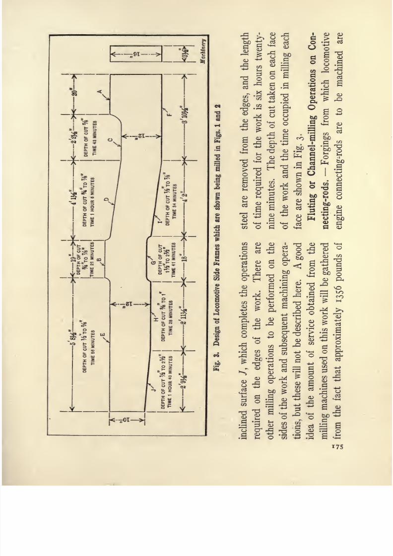
8/13/2019 Production Milling
http://slidepdf.com/reader/full/production-milling 189/296
=^*-^H I
T
.s
1
iooa > M
-
^ x ^ _,o '^ 5 .
^.2 ^ 0,
_<
|*-'
^ r O
o ^
II
CJ fo .S
o 3
w .sP
gs
o
5 ,Q
r wj
S ^ I .
I
.9
^*
| a s .a e
SE | >
4H a o
a
O o<> ^ -M
M-t O
0)
Q- ^ bo
I ^ jj oI-^H
QJ CJ ^
^2^- a g^ ^ ^ b) *->
1 1 -B . 2 6 2
175

8/13/2019 Production Milling
http://slidepdf.com/reader/full/production-milling 190/296
I 76 PRODUCTION MILLING
formed by the same general method as described for milling
side frames. Consequently a detailed description of the
preliminary operationsis
unnecessary. Figures 4and
5
show the performance of what is variously known as the chan-
neling or fluting operation. Three cutters mill the channel
in three forgings which are set up on the machine at a time.
For these channeling operations, the machine cannot be
Fig. 4. Slabbing Type of Milling Machine equipped for the Per-
formance of Channeling Operation on Locomotive
Connecting-rods
operated under as severe conditions of speed and feed as in
the case of plain slabbing operations, because it is more diffi-
cult to dissipate the heat generated by the cutters, owing to
the fact that they are more closely surrounded by the metal.
The method of setting up these forgings for milling the
channels is apparent from the illustration. The conditions
of speed and feed, and the time allowed by one well-known

8/13/2019 Production Milling
http://slidepdf.com/reader/full/production-milling 191/296
PRACTICE IN LOCOMOTIVE SHOPS 177
locomotive plant for this operation are as follows: On the
connecting-rods shown in process of milling, the channels are
4jinches wide
byiff inches
deep by
10 feet long; and the
forgings are made of 45- to 5o-point carbon steel. For the
channel-milling, the rate of feed is from 2\ to 3 inches per
minute, this being all that the milling cutters will stand with-
out excessive wear. In this plant, a feed of 5^ inches per
Fig. 5. Close View of the Work and Cutters on the Slabbing
Type of Milling Machine shown completely in Fig. 4
minute has been employed with a cutting speed of 80 feet per
minute, but operating under such severe conditions,it
wasfound that the rapid wear of the milling cutters more than
offsets the improved rate of production. Operating with a
feed not exceeding 3 inches per minute, the milling cutters are
good for three settings, that is to say, for milling the flutes
on both sides of nine connecting-rods, before they require
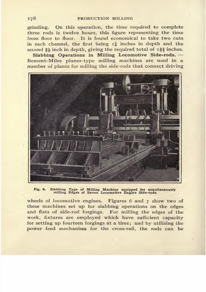
8/13/2019 Production Milling
http://slidepdf.com/reader/full/production-milling 192/296
i 78 PRODUCTION MILLING
grinding. On this operation, the time required to complete
three rods is twelve hours, this figure representing the time
from floor to floor. It is found economical to take two cuts
in each channel, the first being i inches in depth and the
second f^ inch in depth, giving the required total of iff inches.
Slabbing Operations in Milling Locomotive Side-rods. -
Bement-Miles planer-type milling machines are used in a
number of plants for milling the side-rods that connect driving
Fig. 6. Slabbing Type of Milling Machine equipped for simultaneouslymilling Edges of Seven Locomotive Engine Side-rods
wheels of locomotiveengines. Figures
6 and.7
show two of
these machines set up for slabbing operations on the edges
and flats of side-rod forgings. For milling the edges of the
work, fixtures are employed which have sufficient capacity
for setting up fourteen forgings at a time; and by utilizing the
power feed mechanism for the cross-rail, the rods can be
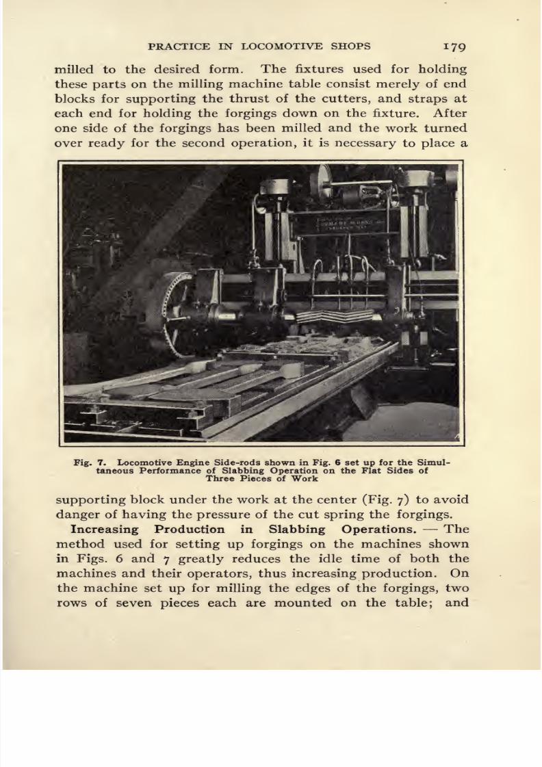
8/13/2019 Production Milling
http://slidepdf.com/reader/full/production-milling 193/296
PRACTICE IN LOCOMOTIVE SHOPS 179
milled to the desired form. The fixtures used for holding
these parts on the milling machine table consist merely of end
blocks for supporting the thrust of the cutters, and straps at
each end for holding the forgings down on the fixture. After
one side of the forgings has been milled and the work turned
over ready for the second operation, it is necessary to place a
Fig. 7. Locomotive Engine Side-rods shown in Fig. 6 set up for the Simul-
taneous Performance of Slabbing Operation on the Flat Sides of
Three Pieces of Work
supporting block under the work at the center (Fig. 7) to avoid
danger of having the pressure of the cut spring the forgings.
Increasing Productionin
Slabbing Operations.
- -
Themethod used for setting up forgings on the machines shown
in Figs. 6 and 7 greatly reduces the idle time of both the
machines and their operators, thus increasing production. On
the machine set up for milling the edges of the forgings, two
rows of seven pieces each are mounted on the table; and

8/13/2019 Production Milling
http://slidepdf.com/reader/full/production-milling 194/296
l8o PRODUCTION MILLING
when the pieces are set up for milling the side faces, two rows
of three forgings each are set up ready for this operation.
This is not in
anysense an
applicationof
string fixtures,however. A brief inspection of the illustrations will make it
apparent that it is impracticable to continue the feed move-
ment of the table in order to bring the second row of forg-
ings under the milling cutters. The method actually followed
in loading and unloading the fixture shown on these machines
is as follows: One row of forgings is set up in either the front
or rear fixture, as the case may be, and these forgings are
brought into the proper relation to the milling cutters, after
which the power feed is engaged. Then, while forgings held
in the first fixture are being milled, the machine operator
unloads the milled pieces from the second fixture and sets
up fresh forgings ready for the next operation. After the cut
has been taken on the parts held in the first fixture, the cross-
rail is raised to traverse the table over to bring the pieces set
up in the second fixture into the milling position. Setting up
two sets of fixtures and using them alternately in this way
shows an improvement in production time as compared with
the use of only one set of fixtures.
Capacity of Planer-type Milling Machines for Removing
Metal. Properly designed planer-type milling machines are
the most rapid to use where heavy forgings and castings re-
quire a considerable amount of metal to be removed in orderto bring them to the required form. This fact is demonstrated
by tests made by the Niles-Bement-Pond Co. on machines of
this type. The following data gives the results of such a test
made on a 45-inch connecting-rod milling machine of the
three-motor type. The driving motor used for making the
test developed 90 horsepower, and 50 cubic inches of 30-point
carbon steel
perminute, or no cubic inches of cast iron per
minute were removed. An inserted-tooth cutter used for this
test was 1 8 inches long and provided with high-speed steel
blades. Operating with such a motor, it was found that the
power supplied to the machine was the limiting factor, rather
than any structural limitations of the machine. The size of
8/13/2019 Production Milling
http://slidepdf.com/reader/full/production-milling 195/296
PRACTICE IN LOCOMOTIVE SHOPS l8l
connecting-rod milling machine used for the test is not ordi-
narily equipped with so powerful a driving motor. For normal
conditions of operation, a 4o-horsepower motor is used, and
the machine is then capable of removing from 20 to 25 cubic
inches of 3o-point carbon steel per minute, and from 45 to 55
cubic inches of cast iron per minute. In slabbing operations,
that is to say, in taking broad, shallow cuts, the milling cutters
are in contact with a much broader area than in connecting-
rod channeling operations, as a result of which the slabbing
cutters work under more favorable conditions for the dissipa-
tion of heat. For this reason, more metal can be removed in
a given length of time than is true in milling channels in
connecting-rods.
With the exception of friction losses, the full power of the
driving motor is delivered to the spindle of this machine, as
the feed mechanism is driven from a separate motor wired to
the driving motor in such a way that when the spindle is
stopped the table feed is also automatically disengaged.
With such an arrangement, it is impossible to have the table
continue feeding when the spindle comes to rest. One im-
portant advantage secured by providing a separate feed motor
is that the rate of feed is made independent of the spindle
speed, thus adapting the machine for milling materials re-
quiring the use of high speed and low feed, or vice versa. This
separate feed motor is fond useful when milling rough forg-
ings that are likely to have inequalities in the amount of metal
to be removed, thus making it desirable to reduce or increase
the rate of feed at different points. The feed motor is of the
variable speed type, provides a wide range of feeds with very
small changes, will adapt itself to a reasonble overload, and
is also used for operating the fast traverse of the table, a switch
being provided for that
purpose.
Animportant
feature in the
design of planer milling machines is to provide an elastic
medium in the feed mechanism in order to protect the cutters
and machine in case an unusual strain is caused by a hard spot
in the work.
8/13/2019 Production Milling
http://slidepdf.com/reader/full/production-milling 196/296
CHAPTER VI
STRING MILLING FIXTURES
FOR milling large numbers of duplicate parts it will fre-
quently be found desirable to use the familiar string type of
work-holding fixture which may be employed on practically
any kind of milling machine. One advantage in using this
fixture is that a number of parts can be set up at a time, so
that the milling machine is kept running for a considerable
period before it becomes necessary to stop the spindle, unload
the fixture, and return the table to the starting point. The
ratio of idle time to operating time is thus substantially
reduced.
Method of Loading String Fixtures. Variations in the
conditions under which milling machines are operated make
it necessary to modify the method of loading and unloading
string fixtures. Where either the size of the pieces to be milled
or the rate of feed that must be employed allows sufficient
time while a piece of work is passing between the cutters to
enable the operator to set up a blank in an adjacent station of
the fixture, the best method is to unload the milled parts as
soon as they have passed out of engagement with the cutters.
After the last station on the fixture has been unloaded and
the table has been returned to the starting point, the milling
machine operator sets up a piece of work in the station nearest
to the cutters and starts the feed mechanism. He then sets
up pieces of work in the remaining stations, working from the
position nearest to the cutters toward the opposite end of
the fixture. In this way, the machine and the operator are
idle for a minimum length of time. It frequently happens,
however, that the pieces to be milled are so small or that the
rate of feed is so high, tljat insufficient time is allowed, while
one piece of work is fed between the cutters, to allow the opera-
182

8/13/2019 Production Milling
http://slidepdf.com/reader/full/production-milling 197/296
STRING FIXTURES 183
tor to set up a piece in the next station. Under such condi-
tions, either several of the stations or the entire fixture should
beloaded,
before the feed is engaged; but even when such
conditions are encountered, a substantial reduction on produc-
tion time will be effected through the use of string fixtures,
as compared with many other types of fixtures in which only
one piece can be set up at a time, and where it is necessary to
Fig. 1. Kempsmith No. 33 Lincoln-type Milling Machine equippedwith Stellite Cutters for straddle-milling Gear-box Levers
stop the machine and return the table after each separate
piece has been milled.
Milling Gear-box Levers. The milling operation shown in
Fig. i is interesting not only as a good example of string fix-
ture design, but because the cutters are made of stellite. The
parts being milled are levers for use in the gear-box on either
the No. 2 or No. 3 plain or universal milling machines built
by the Kempsmith Mfg. Co. As this firm manufactures large
numbers of these levers, a very satisfactory method of milling
on a quantity production basis has been developed. The ma-
chine illustrated is of the Kempsmith No. 33 Lincoln type; and
the string fixture holds ten castings which are straddle-milled

8/13/2019 Production Milling
http://slidepdf.com/reader/full/production-milling 198/296

8/13/2019 Production Milling
http://slidepdf.com/reader/full/production-milling 199/296
STRING FIXTURES 185
work shown at B is held by a pin E that slides through holes in
the work and through two other holes drilled so as to be in
accurate alignment in the bottom of block D and in block F.
By holding one forging with its offset end extending down-
ward and the other forging with its offset end extending up-
ward, the opposite ends of these two forgings are so located
on blocks C that they may be milled by a single passage under
a formed milling cutter, which produces a convex surface on
the work of the required radius of curvature. Posts are pro-
Fig. 2. Kempsmith No. 3 Plain Milling Machine equipped for
milling a Convex Surface on Clutch Shifter Yoke Forgings
vided on the bed of the fixture to support two straps G which
hold the pieces of work down on the tops of blocks C. To
facilitate loading and unloading the fixture, these straps G
are slotted, so that by merely giving the clamping nuts a half
turn, it is possible to draw the straps back from their position
over the work, instead of having to remove the nuts from
their bolts in order to lift the straps off. In this way, a great
saving is effected in the setting-up time.
After the two forgings have been milled while held in the
position shown in Fig. 2, they are removed from the fixture
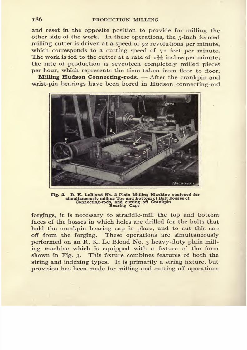
8/13/2019 Production Milling
http://slidepdf.com/reader/full/production-milling 200/296
186 PRODUCTION MILLING
and reset in the opposite position to provide for milling the
other side of the work. In these operations, the 3-inch formed
milling cutter is driven at a speed of 92 revolutions per minute,
which corresponds to a cutting speed of 72 feet per minute.
The work is fed to the cutter at a rate of lyi inches per minute;
the rate of production is seventeen completely milled pieces
per hour, which represents the time taken from floor to floor.
Milling Hudson Connecting-rods. After the crankpin and
wrist-pin bearings have been bored in Hudson connecting-rod
Fig. 3. R. K. LeBlond No. 3 Plain Milling Machine equipped for
simultaneously milling Top and Bottom of Bolt Bosses of
Connecting-rods, and cutting off Crankpin
Bearing Caps
forgings, it is necessary to straddle-mill the top and bottom
faces of the bosses in which holes are drilled for the bolts that
hold the crankpin bearing cap in place, and to cut this cap
off from the forging. These operations are simultaneously
performed on an R. K. Le Blond No. 3 heavy-duty plain mill-
ing machine which is equipped with a fixture of the form
shown in Fig. 3. This fixture combines features of both the
string and indexing types. It is primarily a string fixture, but
provision has been made for milling and cutting-off operations
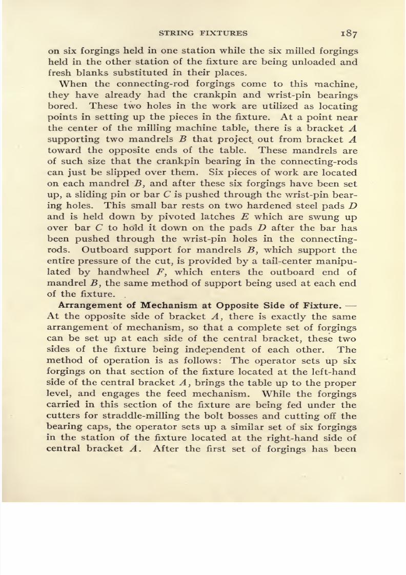
8/13/2019 Production Milling
http://slidepdf.com/reader/full/production-milling 201/296
STRING FIXTURES 187
on six forgings held in one station while the six milled forgings
held in the other station of the fixture are being unloaded and
fresh blanks substituted in their places.
When the connecting-rod forgings come to this machine,
they have already had the crankpin and wrist-pin bearings
bored. These two holes in the work are utilized as locating
points in setting up the pieces in the fixture. At a point near
the center of the milling machine table, there is a bracket A
supporting two mandrels B that project out from bracket Atoward the opposite ends of the table. These mandrels are
of such size that the crankpin bearing in the connecting-rods
can just be slipped over them. Six pieces of work are located
on each mandrel B, and after these six forgings have been set
up, a sliding pin or bar C is pushed through the wrist-pin bear-
ing holes. This small bar rests on two hardened steel pads Dand is held down by pivoted latches E which are swung up
over bar C to hold it down on the pads D after the bar has
been pushed through the wrist-pin holes in the connecting-
rods. Outboard support for mandrels B}which support the
entire pressure of the cut, is provided by a tail-center manipu-
lated by handwheel F, which enters the outboard end of
mandrel B, the same method of support being used at each end
of the fixture.
Arrangement of Mechanism at Opposite Side of Fixture. -
At theopposite
side of bracketA,
there is
exactly the samearrangement of mechanism, so that a complete set of forgings
can be set up at each side of the central bracket, these two
sides of the fixture being independent of each other. The
method of operation is as follows: The operator sets up six
forgings on that section of the fixture located at the left-hand
side of the central bracket A, brings the table up to the proper
level, and engages the feed mechanism. While the forgings
carried in this section of the fixture are being fed under the
cutters for straddle-milling the bolt bosses and cutting off the
bearing caps, the operator sets up a similar set of six forgings
in the station of the fixture located at the right-hand side of
central bracket A. After the first set of forgings has been

8/13/2019 Production Milling
http://slidepdf.com/reader/full/production-milling 202/296
188 PRODUCTION MILLING
milled, the table feeds across to bring the milling cutters into
engagement with the second group of forgings. Then the
operator moves over to the other side of the table to remove
the milled forgings and be ready to set up fresh blanks in
their places. After the second group of forgings has been
milled, the table is lowered sufficiently to allow it to be trav-
ersed back to the starting point without interference from
the milling cutters. The table is then raised to bring the work
into proper relationship with the milling cutters, as determined
Fig. 4. Cincinnati No. 2 Plain Milling Machine equipped forStraddle-milling Top and Bottom of Bolt Bosses on
Connecting-rods, and cutting off Crankpin Bearing Caps
by a stop, after which the left-hand side of the fixture is loaded
and the feed mechanism is again engaged. This cycle of
operations may be repeated indefinitely with very little loss
of time for either the machine or its operator.
After the bolt bosses have been milled and the bearing cap
cut off at one side, however, the six forgings must be removed
from the fixture, turned over, and again set up in the same
fixture ready for a similar operation on the opposite side of
each piece. An improvement of this condition could be made
in either of two ways. If it were required to use the same mill-
ing machine which is now employed, this could be done by

8/13/2019 Production Milling
http://slidepdf.com/reader/full/production-milling 203/296
STRING FIXTURES 189
so constructing the fixture that the entire string of forgings
could be taken out, turned over, and .reset, without requiring
the individual forgings to be removed from their
supportingmandrel. This idea is illustrated in Fig. 4. An even better
arrangement is accomplished at a certain plant where this
operation is performed on a semi-automatic milling ma-
chine equipped with two spindles. With a tool of this type,
the straddle-milling operations and the sawing off of the
bearing cap may be simultaneously accomplished at both sides
of the connecting-rod forgings, thus greatly reducing produc-
tion time through eliminating the necessity of resetting the
work and performing a second operation. In performing this
operation on the machine equipped as shown in Fig. 3, the
cutters run at 60 revolutions per minute, and owing to varia-
tions in their diameters they have speeds of 79, 63, and 55 feet
per minute, respectively. The work is fed to the cutters at
the rate of 3 inches per minute, and the rate of production is
300 connecting-rods in an eight-hour working day.
Milling Continental Connecting-rods. In Fig. 4 there is
shown the method used for performing the same milling opera-
tion on Continental connecting-rods which is illustrated in
Fig. 3. This job is done on a Cincinnati No. 2 miller. Al-
though the methods used by these two companies are similar
in their essential principles, the plan of setting up the work
differs in several details. Figure 4 shows that instead of hav-
ing a central bracket, with mandrels projecting out in opposite
directions for holding six connecting-rod forgings at each side
of the fixture, it is possible on this machine to set up a string
of nine forgings on two mandrels through the crankpin and
wrist-pin bearing holes. These mandrels are entirely separate
from the body of the fixture, so that the work and mandrels
maybe removed as a unit and turned over for
straddle-millingand cutting-off operations on the opposite side of the work.
Such a unit can, of course, be much more quickly removed and
set back in the fixture than is possible where individual forg-
ings must be taken off the mandrels and put back separately
after being turned over. The mandrel which passes through
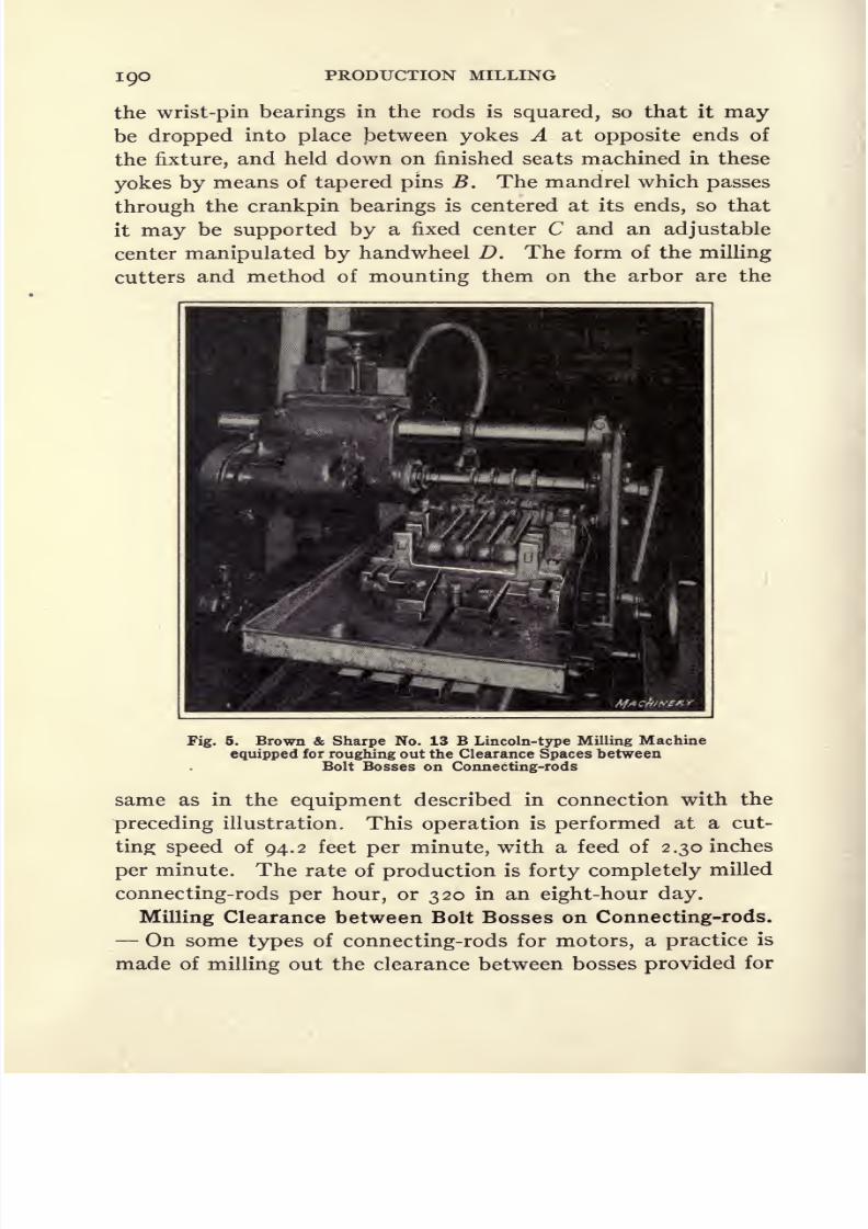
8/13/2019 Production Milling
http://slidepdf.com/reader/full/production-milling 204/296
igo PRODUCTION MILLING
the wrist-pin bearings in the rods is squared, so that it maybe dropped into place Between yokes A at opposite ends of
the fixture, and held down on finished seats machined in these
yokes by means of tapered pins B. The mandrel which passes
through the crankpin bearings is centered at its ends, so that
it may be supported by a fixed center C and an adjustable
center manipulated by handwheel D. The form of the milling
cutters and method of mounting them on the arbor are the
Fig. 5. Brown & Sharpe No. 13 B Lincoln-type Milling Machine
equipped for roughing out the Clearance Spaces betweenBolt Bosses on Connecting-rods
same as in the equipment described in connection with the
preceding illustration. This operation is performed at a cut-
ting speedof
94.2feet
per minute,with a feed of 2.
30inches
per minute. The rate of production is forty completely milled
connecting-rods per hour, or 320 in an eight-hour day.
Milling Clearance between Bolt Bosses on Connecting-rods.
On some types of connecting-rods for motors, a practice is
made of milling out the clearance between bosses provided for

8/13/2019 Production Milling
http://slidepdf.com/reader/full/production-milling 205/296
STRING FIXTURES 191
bolts that secure the caps in place on the connecting-rods,
instead of forging these bosses on the work. For this clear-
ance milling operation, two machines are used which perform
a roughing and a finishing operation, respectively. These
machines are illustrated in Figs. 5 and 6. Figure 5 shows a
Browne & Sharpe No. 136 Lincoln type of machine, on which
the first operation is performed. After this miller has done
its work, the two mandrels on which four connecting-rod forg-
Fig. 6. No. 4 Cincinnati Milling Machine equipped with FormedCutters for finish-milling Clearance Spaces between
Bolt Bosses on Connecting-rods
ings are carried, are removed from the machine with their
work as a single unit, and transferred to the No. 4 Cincinnati
milling machine,illustrated in
Fig. 6, on which the four forg-
ings are set up ready for the finish-milling operation in the
clearance grooves. As the mandrels on which the work is
carried are transferred from one machine to the other, the
work-holding fixtures used on both machines must be of the
same design. The only difference in the equipment of these

8/13/2019 Production Milling
http://slidepdf.com/reader/full/production-milling 206/296
IQ2 PRODUCTION MILLING
two machines is that plain .milling cutters are used for the
roughing operation, while formed cutters are employed for
finishing the grooves. The work-holding fixture is best illus-
trated in Fig. 6, to which attention is called in connection
with the following description.
Forgings to be milled by the machines shown in Figs. 5
and 6 are clamped to the mandrel which passes through the
crankpin bearings. This mandrel has a collar at one end, and
it is threaded at the opposite end; but in order to facilitate
assembling forgings on the mandrel, the clamping nut is
made small enough to pass through the crankpin bearing. A
C-shaped washer slips under this nut, the washer being of suffi-
cient size to afford a bearing surface on which the pressure of
the nut is applied to the work, in order to clamp it firmly
against the collar at the opposite end of the mandrel. At the
wrist-pin end, the connecting-rod forgings are held on a small
mandrel which is merely a sliding fit through these bearings
without being clamped in place, the function of this mandrel
being simply to support the end of the forgings and hold them
in the desired alignment. It has already been noted that
four connecting-rods are assembled on these two mandrels to
constitute a unit which may be removed from the machine
on which the first operation is performed and transferred to
the second machine, and that on both machines, the design
of thework-holding
fixture is the same.
Reference to Fig. 6 will show that at the front end of the
fixture there are V-blocks A to hold the round ends of mandrel
B on which the work is clamped. A strap C at each end of
the mandrel holds it down in the V-block, and a compression
spring D is placed under each of these straps so that when
the nut is loosened, the strap is automatically raised. The
mandrel which passes through the wrist-pin bearings in the
connecting-rods is squared at each end to rest on hardened
steel pads placed between blocks E. When the mandrel is
dropped into place, two wedges F are driven into openings
in the blocks E to hold the squared ends of this mandrel down
on their seats in the fixture. On the roughing operation, the
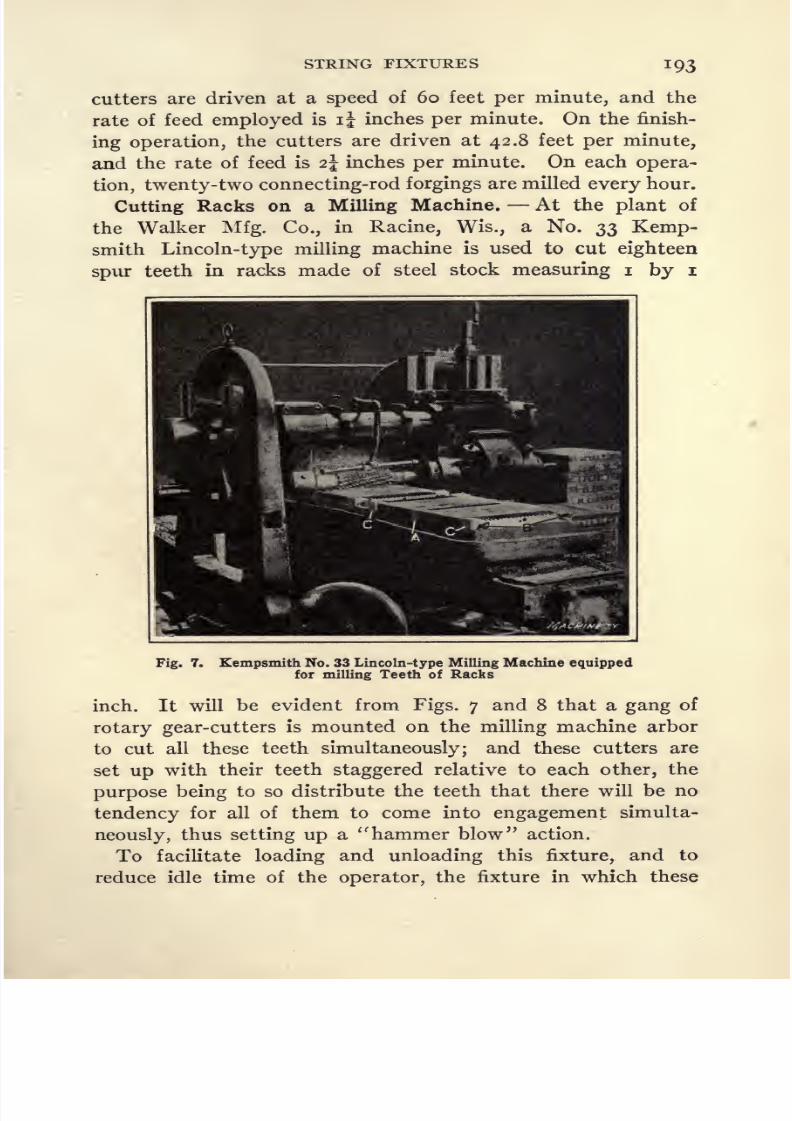
8/13/2019 Production Milling
http://slidepdf.com/reader/full/production-milling 207/296

8/13/2019 Production Milling
http://slidepdf.com/reader/full/production-milling 208/296
194 PRODUCTION MILLING
blanks are held is made in four sections which may be loaded
and unloaded independently of each other. As a result, the
operator can load the first section of the fixture and then
engage the feed mechanism. Six blanks are mounted in each
section of the fixture, and as the rate of feed is one inch per
minute, this allows the operator six minutes in which to load
the second section of the fixture, which is really more time
than he requires. After the last section of the fixture has
been loaded, the operator goes around to the back of the ma-
Fig. 8. Opposite End of Milling Machine working on the Rack-
cutting Operation illustrated in Fig. 7
chine and starts removing milled racks from the fixture, so
that after the last rack comes out from under the cutters it is
merely necessary to unload the last section of the fixture before
the table is returned. This method reduces the idle time of
both the operator and the machines. The fixture is of simple
design. Each of its four sections holds six blanks, and two
sections are divided by a stop-bar A, against which the six
pieces in .each section are clamped. Set-screws B are carried
in end bars C; and by tightening these set-screws, the rack

8/13/2019 Production Milling
http://slidepdf.com/reader/full/production-milling 209/296
STRING FIXTURES 195
blanks are clamped against opposite sides of the stop-bar A.
The cutters are driven at a speed of 71 feet per minute, and
the rate of feed is i inch per minute. The rate of production
obtained is 60 racks per hour, which includes the time of
loading and unloading the fixture.
Use of Milling Machine Vise as a String Fixture. At a
certain automobile plant, it is necessary to perform a slot-
milling operation in the brake-lever for a passenger car. The
Fig. 9. R. K. LeBlond No. 3 Plain Milling Machine used for
Slotting Operation on Brake-levers
slot milled in these small levers must be located at an angle
to the axis of the lever arm, and it was found possible to
utilize an ordinary milling machine vise for this simple opera-
tion. The work is done on a No. 3 LeBlond plain milling
machine, and Fig. 9 shows a close view of the vise set on the
table of this machine for holding a string of five brake-levers.
As far as clamping the work is concerned, the milling machine
vise answers every requirement, but it is also necessary to
locate the pieces of work at exactly the proper angle. For
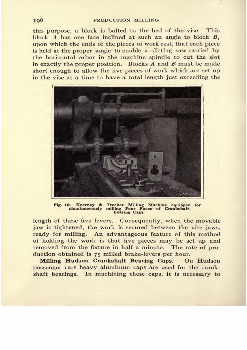
8/13/2019 Production Milling
http://slidepdf.com/reader/full/production-milling 210/296
196 PRODUCTION MILLING
this purpose, a block is bolted to the bed of the vise. This
block A has one face inclined at such an angle to block B,
upon which the ends of the pieces of work rest, that each piece
is held at the proper angle to enable a slitting saw carried by
the horizontal arbor in the machine spindle to cut the slot
in exactly the proper position. Blocks A and B must be made
short enough to allow the five pieces of work which are set up
in the vise at a time to have a total length just exceeding the
Fig. 10. Kearney & Trecker Milling Machine equipped for
simultaneously milling Four Faces of Crankshaft-
bearing Caps
length of these five levers. Consequently, when the movable
jaw is tightened, the work is secured between the vise jaws,
ready for milling. An advantageous feature of this method
of
holdingthe work is that five
pieces maybe set
upand
removed from the fixture in half a minute. The rate of pro-
duction obtained is 75 milled brake-levers per hour.
Milling Hudson Crankshaft Bearing Caps. On Hudson
passenger cars heavy aluminum caps are used for the crank-
shaft bearings. In machining these caps, it is necessary to

8/13/2019 Production Milling
http://slidepdf.com/reader/full/production-milling 211/296
STRING FIXTURES 197
mill four faces of the work, and in order to mill these surfaces
simultaneously, a Kearney & Trecker milling machine is
equipped as illustrated in Fig. 10. Four cutters are mounted
on the arbor two inserted-tooth mills for facing the large
side surfaces of the work, and two plain cutters for milling the
small surfaces at each side of the bearing groove. Four pieces
of work are mounted in a string fixture on the table, and this
fixture is equipped with a quick-acting clamping mechanism
to facilitate loading pieces in the fixture, or removing them
after the milling operation has been completed. Between
each pair of bearing caps there is a bolt A, which holds downa semi-cylindrical shaped strap B fitted into the bearing groove
in the two caps at each side of this clamping bolt.
The hole in strap B is made large enough to clear the nut
on bolt Atso that the strap may be dropped over this bolt
and then pushed sidewise in order that the groove cut in the
side of the hole may allow the strap to slide under the nut
readyfor
clampingit down on the work.
Figure10 shows
that the work must be so located that the sides of the bearing
caps will be milled square with the ends. This result is accom-
plished by having small blocks C on the bed of the fixture
come into contact with ribs extending across the sides of the
work. The way in which these blocks C locate the work
will be readily understood by referring to the piece which is
shown clamped in place on the fixture. Owing to the different
sizes of the cutters used for this operation, the speeds vary
considerably, the rates employed being 280 and 220 feet per
minute, respectively, with a feed of 18 inches per minute.
If the material were not aluminum, such rates of speed and
feed could not be successfully employed. In an eight-hour
working day, the output of each machine is 700 bearing caps.
Milling Retainer Rings in Roller Bearing Raceways. In
making roller bearings of the type manufactured by the Hyatt
Roller Bearing Co., grooves must be milled in the outer race-
ways to form an anchorage for the roller retainers. For this
operation, satisfactory results are obtained by the use of a
Kearney & Trecker vertical-spindle milling machine equipped

8/13/2019 Production Milling
http://slidepdf.com/reader/full/production-milling 212/296
PRODUCTION MILLING
Fig. 11. Unusual Form of Fixture provided on a Kearney &Trecker Machine used for milling Grooves in Outer
Raceways of Roller Bearings
Fig. 12. Same Milling Machine and Work-holding Fixture illus-
trated in Fig. 11, but with the Fixture closed, ready for
milling the Three Retainer Anchorage Grooves
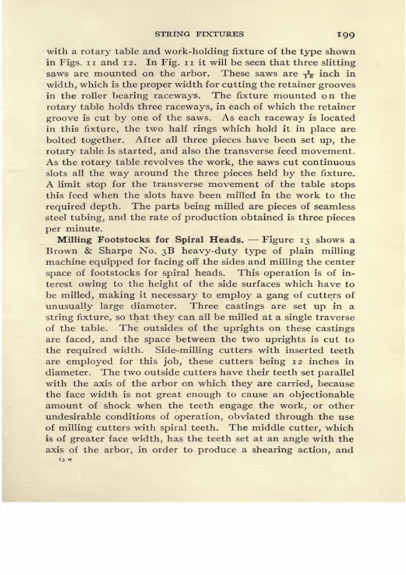
8/13/2019 Production Milling
http://slidepdf.com/reader/full/production-milling 213/296
STRING FIXTURES 199
with a rotary table and work-holding fixture of the type shown
in Figs, ii and 12. In Fig. n it will be seen that three slitting
saws are mounted on the arbor. These saws are
&inch in
width, which is the proper width for cutting the retainer grooves
in the roller bearing raceways. The fixture mounted on the
rotary table holds three raceways, in each of which the retainer
groove is cut by one of the saws. As each raceway is located
in this fixture, the two half rings which hold it in place are
bolted together. After all three pieces have been set up, the
rotary table is started, and also the transverse feed movement.
As the rotary table revolves the work, the saws cut continuous
slots all the way around the three pieces held by the fixture.
A limit stop for the transverse movement of the table stops
this feed when the slots have been milled in the work to the
required depth. The parts being milled are pieces of seamless
steel tubing, and the rate of production obtained is three pieces
per minute.
Milling Footstocks for Spiral Heads. Figure 13 shows a
Brown & Sharpe No. 36 heavy-duty type of plain milling
machine equipped for facing off the sides and milling the center
space of footstocks for spiral heads. This operation is of in-
terest owing to the height of the side surfaces which have to
be milled, making it necessary to employ a gang of cutters of
unusually large diameter. Three castings are set up in a
string fixture, so that they can all be milled at a single traverseof the table. The outsides of the uprights on these castings
are faced, and the space between the two uprights is cut to
the required width. Side-milling cutters with inserted teeth
are employed for this job, these cutters being 12 inches in
diameter. The two outside cutters have their teeth set parallel
with the axis of the arbor on which they are carried, because
the face width is not great enough to cause an objectionable
amount of shock when the teeth engage the work, or other
undesirable conditions of operation, obviated through the use
of milling cutters with spiral teeth. The middle cutter, which
is of greater face width, has the teeth set at an angle with the
axis of the arbor, in order to produce a shearing action, and

8/13/2019 Production Milling
http://slidepdf.com/reader/full/production-milling 214/296
200 PRODUCTION MILLING
these teeth are nicked to break up the chips. The fixtures
used for holding the work for this milling operation are of
simpledesign,
consisting merely
of bolts fitted into the T-slots
on the table to hold straps down on the flange which extends
around the base of each footstock casting.
Multiple Work-holding Fixtures Placed Side by Side.
The term string milling fixture is generally applied to that
class of fixture in which the castings are placed in a row on
Fig. 13. Milling Footstocks for Spiral Heads on a Brown &Sharpe No. 3B Heavy-duty Plain Milling Machine
the milling machine table, running in a direction parallel to
the line of travel of the table, so that all of the castings can be
milled with a single cutter, or
gangof cutters, mounted on
the arbor. In some cases, however, it may be found more
desirable to set up the work in fixtures that hold the castings
or forgings side by side, instead of end to end. A case in point
is illustrated in Fig. 14, which shows a Brown & Sharpe No.
56 plain milling machine engaged in simultaneously rough-

8/13/2019 Production Milling
http://slidepdf.com/reader/full/production-milling 215/296
STRING FIXTURES 2OI
milling the angular sides of the slides on four milling machine
tables. This kind of job could be performed on a planer or
slabbing type of milling machine equipped with a table of
sufficient length to set the four castings up end to end; and
if such a practice were followed it would be necessary to use
only one milling cutter. However, by performing the opera-
tion as shown in Fig. 14, a less expensive machine is utilized;
Fig. 14. Rough-milling Angular Sides of Slides on Milling
Machine Tables, using a Brown & Sharpe No. 5BMilling Machine
but in order to do so it is necessary to set the castings up side
by side, because the length of the table is insufficient to mount
them in a single row. The castings are set up on two knee-
type fixtures,each of which holds two
castings,one on each
side of the fixture. The same fixture is used to mill the opposite
angular sides of the slide, the four pieces of work being merely
turned over and reset for taking the second cut.
Milling Two Grinding Machine Tables Simultaneously.
The No. 56 plain milling machines are used for simultane-

8/13/2019 Production Milling
http://slidepdf.com/reader/full/production-milling 216/296
202 PRODUCTION MILLING
ously milling two tables for Brown & Sharpe grinding ma-
chines, as shown in Fig. 15. The reason for setting up the
castings side by side on this machine is the same as explained
in connection with the job illustrated in Fig. 14. The two
grinding machine table castings are held at opposite sides of
a knee fixture, and two gangs of cutters, with six in each
gang, are employed for simultaneously milling the various
surfaces which have to be finished. To hold these castings
Fig. 15. Milling Operation simultaneously performed on TwoGrinding Machine Tables, using a No. 5B Heavy-
duty Brown & Sharpe Milling Machine
back against the locating points, there are four straps A at
each end of the fixture, these straps being provided with lugs
which project inward to engage the flange B on each end of
the castings that have to be milled. By tightening the nuts
over straps A, the lugs on these straps pull the work securely
back against the locating points. Owing to the form of the
castings, the work must be supported to avoid danger of its
being distorted through pressure of the milling cutters. This
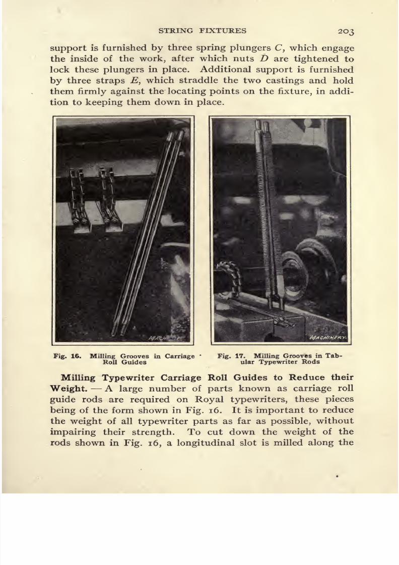
8/13/2019 Production Milling
http://slidepdf.com/reader/full/production-milling 217/296
STRING FIXTURES 203
support is furnished by three spring plungers C, which engage
the inside of the work, after which nuts D are tightened to
lock these plungers in place. Additional support is furnished
by three straps E, which straddle the two castings and hold
them firmly against the locating points on the fixture, in addi-
tion to keeping them down in place.
Fig. 16. Milling Grooves in Carriage*
Fig. 17. Milling Grooves in Tab-
Roll Guides ular Typewriter Rods
Milling Typewriter Carriage Roll Guides to Reduce their
Weight.A
large
number of
parts
known as carriage roll
guide rods are required on Royal typewriters, these pieces
being of the form shown in Fig. 16. It is important to reduce
the weight of all typewriter parts as far as possible, without
impairing their strength. To cut down the weight of the
rods shown in Fig. 16, a longitudinal slot is milled along the

8/13/2019 Production Milling
http://slidepdf.com/reader/full/production-milling 218/296
204 PRODUCTION MILLING
back side of each rod, in order to remove as much surplus
metal as possible. This job is done on one of the Briggs mill-
ing machines built by Gooley & Edlund, Inc. Four of the
carriage roll guides are set up at a time, the fixture consisting
of a speciaji form of vise provided with two openings, in each
of which two of the carriage roll guide rods can be mounted.
The jaws are slightly under-cut so that when they are tightened
on the work, they serve the double purpose of gripping it and
forcing it downward, thus obtaining an accurate location and
secure hold simultaneously. The two outer jaws move inward
from opposite directions and grip the work against the central
jaw, which constitutes the fixed jaw for each of the two vise
openings.
A rather unusual type of fixture feeds the work up against
the milling cutters, in order to cut grooves of the required
depth in the carriage roll guide rods. This fixture is merely
a sub-table on which the special milling vise is mounted, and
by simply throwing over a lever, the work is raised against
the milling cutters so that the groove will be cut to exactly
the proper depth. The reason for this procedure will be made
clear by referring to the form of the work shown in Fig. 16,
where it will be seen that at each end of the carriage roll guide
there is a threaded section, while the groove milled in the
work projects beneath the level of the threads. Consequently
it is notpossible
to mill the
groove bya single horizontal feed
movement of the table; the work must be raised into engage-
ment with the milling cutters at the point where the groove
starts, and then lowered away from the cutters at the opposite
end of the groove. By this method, the groove is cut to the
proper depth and the threads at either end of the work are
not damaged.
Figure 18 shows how this fixture operates. The vise which
holds the work is shown at A . To raise this vise and to bring
the pieces carried by it into engagement with the milling
cutters, lever B is thrown over from the position indicated by
broken lines to the one shown by full lines. Attached to lever
B there is a link C, which has two pivoted levers D and E

8/13/2019 Production Milling
http://slidepdf.com/reader/full/production-milling 219/296
L
-4f--5-v
^
205
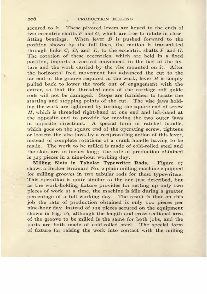
8/13/2019 Production Milling
http://slidepdf.com/reader/full/production-milling 220/296

8/13/2019 Production Milling
http://slidepdf.com/reader/full/production-milling 221/296

8/13/2019 Production Milling
http://slidepdf.com/reader/full/production-milling 222/296
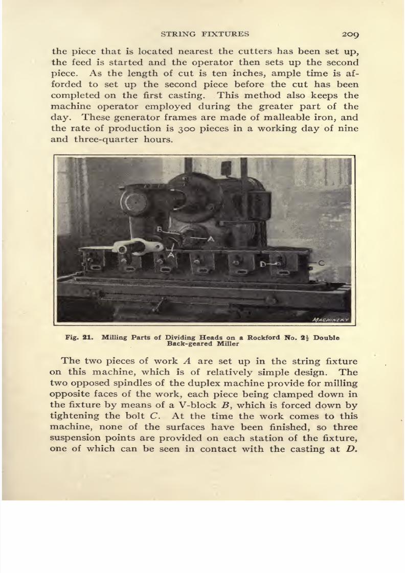
8/13/2019 Production Milling
http://slidepdf.com/reader/full/production-milling 223/296
STRING FIXTURES 209
the piece that is located nearest the cutters has been set up,
the feed is started and the operator then sets up the second
piece. As the length of cut is ten inches, ample time is af-
forded to set up the second piece before the cut has been
completed on the first casting. This method also keeps the
machine operator employed during the greater part of the
day. These generator frames are made of malleable iron, and
the rate of production is 300 pieces in a working day of nine
and three-quarter hours.
Fig. 21. Milling Parts of Dividing Heads on a Rockford No.
Back-geared Miller
Double
The two pieces of work A are set up in the string fixture
on this machine, which is of relatively simple design. The
two opposed spindles of the duplex machine provide for milling
opposite
faces of the
work,each
piece being clampeddown in
the fixture by means of a V-block B, which is forced down by
tightening the bolt C. At the time the work conies to this
machine, none of the surfaces have been finished, so three
suspension points are provided on each station of the fixture,
one of which can be seen in contact with the casting at D.

8/13/2019 Production Milling
http://slidepdf.com/reader/full/production-milling 224/296
210 PRODUCTION MILLING
After the operator has set the second casting up in the fixture,
he moves around to the back of the machine; and as soon as
the first casting has passed out of engagement with the cutters,
he releases the clamping bolt and removes this casting from
the fixture. He is idle during only a short time while the cut
is being completed on the second casting. As soon as this piece
Fig. 22. Milling Surface of Knees for Hand Millers on a Rock-
ford No. 2 Double Back-geared Miller
comes out from between the cutters, the operator removesit
and goes back to the front of the machine to set up fresh cast-
ings for the next operation.
String Fixture for Milling Dividing Head Parts. At the
plant of the Rockford Milling Machine Co., No. 2\ double
back-geared millers are equipped with string fixtures of the

8/13/2019 Production Milling
http://slidepdf.com/reader/full/production-milling 225/296
STRING FIXTURES 211
type shown in Fig. 21, to provide for a combination face-
milling and grooving operation on parts of dividing heads.
Six pieces of work can be set upon the string fixture
employedfor this job. Two spiral cutters A are mounted on the arbor,
with a narrow face cutter B between them, so that at a single
traverse of the table the entire top surface of the work maybe faced by cutters A, while the narrow cutter B mills a
groove at the center. Conforming with the usual practice
where spiral-toothed cutters are used, it will be evident that
Fig. 23. Milling Clutch Teeth on a Rockford No. 2 Double Back-gearedMiller
the machine is set up with the spiral running left-hand at
one side and right-hand at the opposite side, thus avoiding
any tendencyfor the cutters to
developan
endthrust.
Thework-holding fixture is of simple design, consisting of a verti-
cal plate C over which the castings are dropped so that they
may be clamped by means of bolts D. The spindle is driven
at a speed of 64 revolutions per minute and the rate of feed
is 0.076 inch per revolution, which corresponds to a feed of

8/13/2019 Production Milling
http://slidepdf.com/reader/full/production-milling 226/296
212 PRODUCTION MILLING
approximately 4 inches per minute. The cut is T% inch deep
by 4 inches wide and in milling these gray iron castings the
rate of production is one piece in one minute forty-three seconds.
Milling Top of Hand Miller Knees. At the plant of the
Redin & Ekstrom Co., a No. 2 double back-geared Rockford
milling machine, shown in Fig. 22, is employed for milling
the top surface of the knee for hand milling machines. This
illustration shows the application of a vertical milling attach-
ment on production work, an end-mill of sufficient size to
cover the entire surface of the work being utilized with success-
ful results. Four castings are set up at a time. The string
fixture is of simple design, consisting of bolts in the T-slots of
the milling machine table and straps to engage the flanges on
the work. The end-milling cutter is 4 inches in diameter by
6 inches long, and is driven at 106 revolutions per minute
with a feed of 0.070 inch per revolution, which corresponds
to acutting speed
of in feet per minute with a feed of
7.42inches per minute. The depth of cut is f inch, and the
face to be milled is 3^ inches in width. On this job the
total time for milling four pieces of work is six minutes.
Duplex Fixture for Clutch Cutting. In the plant of the
Cotta Transmission Co., a Rockford No. 2 double back-geared
miller is used for a clutch cutting operation.. This machine
is equipped with a duplex^indexing fixture as illustrated in
Fig. 23 ,which provides for simultaneously cutting two clutches
with cutters 3 inches in diameter by |-inch face width. The
clutch teeth are cut in slightly raised bosses A on the gears.
Each gear is mounted on a vertical spindle, these two spindles
being connected by an indexing mechanism B so that turn-
ing crank C simultaneously rotates the two clutch gear blanks
through the necessary angle to locate the work for cutting
the next groove. On this job the cutters are driven at a speed
of 80 revolutions per minute, with a feed of o.no inch per
revolution, which corresponds to a cutting speed of 62.8
feet per minute with a feed of 8.80 inches per minute. The
time required to finish cutting a clutch is approximately four
minutes.

8/13/2019 Production Milling
http://slidepdf.com/reader/full/production-milling 227/296
CHAPTER VII
INDEXING MILLING FIXTURES
IN setting up milling machines for quantity production there
are a number of fundamental principles which must be ob-
served in order to obtain maximum production and quality
workmanship. Although these points, briefly outlined in the
following paragraphs, are simple and obvious, too much em-
phasis cannot be laid on the importance of observing all of
them.
When making arbors for use on milling machines, do not
attempt to use soft machine steel. To give satisfactory service,
arbors should be made of machine steel and first carburized to
increase the carbon content at the surface of the metal. Thenthe arbors are hardened, with the result that their entire sur-
face is covered by a skin of hard steel, which protects them
from becoming bruised or nicked; at the same time, the inner
metal is left soft and tough so that it has ample strength to
resist severe shocks. It may be that an arbor is required for
immediate use, making it impracticable to take the time for
carburizing.In
sucha
case, a fairly satisfactory arbor canbe produced from 6o-point carbon or chrome-nickel steel.
An arbor made of this material is not so good as one made of
machine steel and casehardened, because when it is heat-
treated the hardness extends all the way through the steel,
and without the tough inner core there is more danger of the
arbor breaking.
When a milling machine is set up, the arbor should be put
in place in the spindle and carefully tested with a sensitive
indicator to make sure that it runs true. If the arbor does
not run accurately, a uniform action of the milling cutters
cannot be obtained. For the same reason, it is necessary to
take great care of the taper hole in the machine spindle. When213

8/13/2019 Production Milling
http://slidepdf.com/reader/full/production-milling 228/296
214 PRODUCTION MILLING
the arbor is set up, there should be no chips in the spindle
socket or adhering to the shank of the arbor. Chips will not
only throw the arbor off center, but will also prevent close
engagement between the arbor shank and the spindle socket,
thus making it impossible to secure the required frictional
resistance between the arbor and the milling machine spindle
in which it is mounted.
There is some difference of opinion as to the best form of
outboard support for a milling machine arbor. It is quite
general practice to use a split cylindrical bearing for this
purpose, the claim being made by advocates of the straight
bearing that if a tapered bearing is used to provide means of
adjustment to compensate for wear, the mechanic will in manycases set the bearing too tight, and thus produce a condition
that is worse than would result from the slight amount of lost
motion in a cylindrical bearing. Advocates of the tapered bear-
ing, however,maintain that a
set-upman who has
chargeof
a milling machine department should have the necessary skill
and experience to adjust a tapered bearing properly. De-
pendence cannot be placed upon cold-rolled steel for making
keys for securing milling cutters on their arbors. A good
grade of key stock should be used for this purpose and the
finished keys should be drawn to a spring temper. When the
cutters have been set up on an arbor, care should be taken to
see that they run true and that all of the teeth do their proper
share of the work. Where these conditions are not obtained,
accurate work will not be produced and the life of the cutters
will be greatly reduced. Methods of designing work-holding
fixtures, which is a point of equal importance to those just
given in regard to cutters and arbors, will be fully described
later. The information presented on these topics may be
summarized by saying that it is absolutely essential for both
the cutters and the work to be properly housed in order to
get the best possible results.
The milling machines should be inspected at specified
intervals. If bearings or slides fit badly, or if there is lost
motion between feed-screws and their nuts, accurate results
8/13/2019 Production Milling
http://slidepdf.com/reader/full/production-milling 229/296
INDEXING FIXTURES 215
cannot be obtained; also, such conditions will affect produc-
tion adversely, because when a machine in poor condition is
run at a high speed and heavy feed, therewill
be a tendencyfor the cutters and work to chatter. When this kind of trouble
is experienced, the natural thing is to slow down the speed
and feed in order to eliminate the chattering of the cutters and
work; but this also reduces the rate of production. In manycases such a loss could be avoided by making the necessary
adjustment of bearings, slides, gibs, etc., on the milling machine.
General Types of Indexing Fixtures. On small or medium-
sized machines it will frequently be found advantageous to
use indexing fixtures for holding the work. Such fixtures maybe designed to carry two or more pieces according to condi-
tions; but the general arrangement is to have two stations, so
that the piece or pieces mounted in one station may be milled
while the operator is removing finished parts from another
station and setting up fresh blanks in their places. Then,
after milling the parts held in the operating position, the fixture
is indexed to bring the blanks which have just been set upinto position for milling. The operator then removes the
freshly milled pieces from the fixture. This sequence of move-
ments can be constantly repeated, with little idle time of
either the machine or its operator.
Many successful modifications of design have been worked
out for indexing fixtures to be used for holding pieces of workon milling machines. The simplest of these is represented bya case in which provision is made for merely holding two
pieces of work, so that a piece held in one station of the fixture
can be milled while the other station is unloaded and a fresh
blank set up. It is a common practice, however, to arrange
indexing fixtures so that two or more parts are mounted at
each station, examples of such fixture designs being shown in
Figs, i to 6, inclusive. Another commonly used type of in-
dexing fixture is that employed for turning pieces of work for
successive operations on the different sides, in order to bring
the work to a square, hexagon, or some other desired form.
Examples of this method of designing indexing fixtures are
14 M
8/13/2019 Production Milling
http://slidepdf.com/reader/full/production-milling 230/296
2l6 PRODUCTION MILLING
shown in Figs. 7, 8, and 9. Fixtures of this kind may be made
with a number of collets or other means for holding the work;
and a gang of cutters may be mounted on the milling machine
arbor, one or more of these cutters engaging each piece of
work. The work-holding devices and the indexing mechanism
of the fixture should preferably be geared together so that
turning one handle simultaneously indexes all pieces of work.
Another method of indexing fixture design is that of com-
bining with the indexing principle the features of a string
fixture,which tends to increase rates of
production.An ex-
ample of such a design will be shown further on in this chapter.
Such fixtures consist essentially of a plate, carrying two strings
of work-holding clamps, which is mounted on a pivot midway
between the two ends of the fixture. Not only does such a
method make it possible to take advantage of the string-
fixture principle, but it also avoids practically all the idle time
involved in unloading and resetting fresh pieces of work before
the next operation can be started. After the pieces in one
station of the fixture have been milled, the operator simply
releases the lock-pin and swings the baseplate around, end for
end, so that the string of parts held in the second station of
the fixture are brought into the milling position. Then he
unloads the milled parts and sets up fresh pieces of work,
while those pieces held in the other station are being milled.
Still another application of the indexing type of fixture, for
milling parts of small or medium size, consists of making two
duplicate indexing fixtures which are mounted at opposite
ends of the table. This method is used where both ends of
the work have to be milled. One end of the work, held in the
fixture at the left-hand end of the table, is milled first; then
the table is moved over to allow the cutters to start milling
the work held by the right-hand fixture. While this cut is
being taken, the left-hand fixture is indexed into position for
taking a cut at the opposite end of the work held by this
fixture. The table is then moved back to take this cut and
the right-hand fixture is indexed. While the second cut is
being taken on the work held in the right-hand fixture, the

8/13/2019 Production Milling
http://slidepdf.com/reader/full/production-milling 231/296
INDEXING FIXTURES 217
finished work is removed from the left-hand fixture and a
new piece is set up in its place.
Standard Design of Indexing Fixture. Substantial sav-
ings may often be made in the cost of special tool equipment
required for a variety of machining operations by adopting
standard tool parts which may be adapted to the requirements
of a specified job. A case in point is seen in the indexing mill-
ing fixture illustrated in Figs, i and 2. The body of this
Machinery
Fig. 1. Plan and Cross-sectional Views of the Standard Type of
Indexing Milling Fixture shown in Fig. 2
fixture is now used in most cases where an indexing type of
work-holding fixture is required for a milling operation in the
Detroit plant of the Studebaker Corporation. Such fixtures
are made in quantities, and when a specific job is to be handled,it is only necessary for the tool-room to provide, on the bodyof the fixture, suitable clamps and locating devices for the work
in question, which are simply discarded when a fixture of this
type becomes obsolete. The body of the fixture can be utilized
for another job.
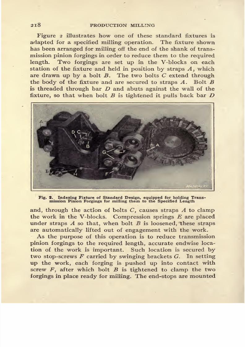
8/13/2019 Production Milling
http://slidepdf.com/reader/full/production-milling 232/296
2l8 PRODUCTION MILLING
Figure 2 illustrates how one of these standard fixtures is
adapted for a specified milling operation. The fixture shown
has been arranged for milling off the end of the shank of trans-
mission pinion forgings in order to reduce them to the required
length. Two forgings are set up in the V-blocks on each
station of the fixture and held in position by straps A, which
are drawn up by a bolt B. The two bolts C extend through
the body of the fixture and are secured to straps A. Bolt B
is threaded through bar D and abuts against the wall of the
fixture, so that when bolt B is tightened it pulls back bar D
Fig. 2. Indexing Fixture of Standard Design, equipped for holding Trans-
mission Pinion Forgings for milling them to the Specified Length
and, through the action of bolts C, causes straps A to clamp
the work in the V-blocks. Compression springs E are placed
under straps A so that, when bolt B is loosened, these straps
are automatically lifted out of engagement with the work.
As the purpose of this operation is to reduce transmission
pinion forgings to the required length, accurate endwise loca-
tion of the work is important. Such location is secured by
two stop-screws F carried by swinging brackets G. In setting
up the work, each forging is pushed up into contact with
screw F, after which bolt B is tightened to clamp the two
forgings in place ready for milling. The end-stops are mounted
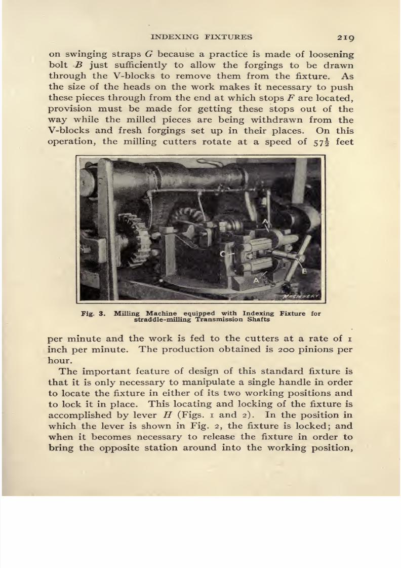
8/13/2019 Production Milling
http://slidepdf.com/reader/full/production-milling 233/296
INDEXING FIXTURES 2IQ
on swinging straps G because a practice is made of loosening
bolt B just sufficiently to allow the forgings to be drawn
through the V-blocks to remove them from the fixture. Asthe size of the heads on the work makes it necessary to push
these pieces through from the end at which stops F are located,
provision must be made for getting these stops out of the
way while the milled pieces are being withdrawn from the
V-blocks and fresh forgings set up in their places. On this
operation, the milling cutters rotate at a speed of 57J feet
Fig.3.
MillingMachine
equippedwith
IndexingFixture for
straddle-milling Transmission Shafts
per minute and the work is fed to the cutters at a rate of i
inch per minute. The production obtained is 200 pinions per
hour.
The important feature of design of this standard fixture is
that it is only necessary to manipulate a single handle in order
to locate the fixture in either of its two working positions andto lock it in place. This locating and locking of the fixture is
accomplished by lever H (Figs, i and 2). In the position in
which the lever is shown in Fig. 2, the fixture is locked; and
when it becomes necessary to release the fixture in order to
bring the opposite station around into the working position,

8/13/2019 Production Milling
http://slidepdf.com/reader/full/production-milling 234/296
220 PRODUCTION MILLING
lever H is swung over against pin /, after which the fixture
may be revolved by hand. When brought to approximately
the required position, lever H is pushed back, thus obtaining
an accurate location of the fixture and locking it in the posi-
tion so obtained.
A better idea of the way in which this fixture is designed
will be obtained by referring to Fig. i. Lever H is carried
by a cross-shaft on which is mounted a cam / that has eccen-
tric beveled flanges around its ends. The fixture consists of
a stationary base K and a table L which may be indexed to
bring the work carried on it into either the milling or the
unloading position, as desired. This table L has a slot cut
in its under side, in which is mounted a bar M, projecting
outward at each side to engage the tapered flanges on cam /.
Consequently, when an approximate location of the table has
been secured through rotating it by hand, the turning of lever
Hcauses cam / to be rotated so that the eccentric beveled
flanges on this cam engage bar M and turn table L slightly,
in either direction, to locate it accurately, after which further
turning of cam J clamps the table firmly in place. The cross-
sectional view shows that the flanges on cam / are cut away
at one side, so that when lever H is swung over into contact
with pin /, the cut away section of the cam allows the table
to be rotated for indexing. When lever H is swung in the
opposite direction, the flanges on the cam engage bar M,
locating and locking it in the manner just described.
Straddle-milling Transmission Main Shafts to Length.-
Figure 3 shows a Becker-Brainard No. 4 milling machine
equipped with a standard indexing fixture which has been
adapted for straddle-milling transmission main shafts to
length. Two forgings are mounted on each station of the
fixture. These forgings are held by V-blocks, in which they
are secured by hooks A, that are tightened on the work by
turning a socket wrench B. This socket wrench turns a screw
which pushes back a rocker link located inside of the fixture;
this link, in turn, is connected to the rear ends of the two
hooks A. When manipulated, this rocker link pulls hooks A

8/13/2019 Production Milling
http://slidepdf.com/reader/full/production-milling 235/296
INDEXING FIXTURES 221
I
I
<
a

8/13/2019 Production Milling
http://slidepdf.com/reader/full/production-milling 236/296
222 PRODUCTION MILLING
back on the forgings and draws them into their seats in the
V-blocks. A sufficiently accurate location of the work may be
obtained from the end of one of the splines on each forging,
which is brought into engagement with a locating plate C.
The remainder of the fixture is of standard design. On this
operation, the rate of production obtained is 135 transmission
shafts per hour.
Straddle-milling Camshafts to Length. The first opera-
tion on camshaft forgings in the Studebaker machine shop is to
Fig. 5. Vertical Milling Machine equipped with Indexing Fixturefor facing Joints of Bearing Caps
straddle-mill them to the specified length on a Becker duplex
milling machine, which is shown in Fig. 4. This machine is
equipped with an indexing fixture of different design from the
standard type used by this company. In this case, two forgings
are held in each station of the fixture, one of the forgings hav-
ing been removed from the V-blocks at the front and laid
on the bed of the machine, in order to show the fixture more
clearly. Endwise location of the work is accomplished by
gages A which fit over one of the bearings on the camshaft.
At both ends of the fixture there are straps B which hold the
two forgings back into their V-blocks. At each end of the
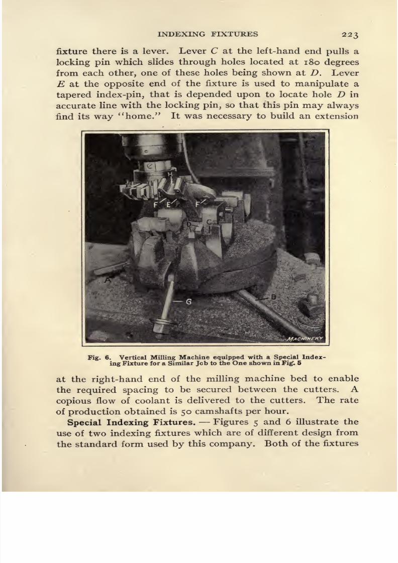
8/13/2019 Production Milling
http://slidepdf.com/reader/full/production-milling 237/296
INDEXING FIXTURES 223
fixture there is a lever. Lever C at the left-hand end pulls a
locking pin which slides through holes located at 180 degrees
from each other, one of these holes being shown at D. Lever
E at the opposite end of the fixture is used to manipulate a
tapered index-pin, that is depended upon to locate hole D in
accurate line with the locking pin, so that this pin may always
find its way home. It was necessary to build an extension
Fig. 6. Vertical Milling Machine equipped with a Special Index-
ing Fixture for a Similar Job to the One shown in Fig*. 5
at the right-hand end of the milling machine bed to enable
the required spacing to be secured between the cutters. Acopious flow of coolant is delivered to the cutters. The rate
of production obtained is 50 camshafts per hour.
Special Indexing Fixtures. Figures 5 and 6 illustrate the
use of two indexing fixtures which are of different design from
the standard form used by this company. Both of the fixtures

8/13/2019 Production Milling
http://slidepdf.com/reader/full/production-milling 238/296

8/13/2019 Production Milling
http://slidepdf.com/reader/full/production-milling 239/296

8/13/2019 Production Milling
http://slidepdf.com/reader/full/production-milling 240/296
226 PRODUCTION MILLING
than those shown in the preceding illustration, as a result of
which the rate of production obtained is twice as high, or 80
bearing caps per hour.
Indexing Fixture for Producing Required Form of Work.
The term indexing is generally understood to imply the
rotation of the work through part of a turn, to provide for
taking the next cut, as, for instance, cutting the next tooth
of a gear blank or for milling the next side of a square or other
Fig. 8. Opposite Side of Work-holding Fixture shown in Fig. 7
showing the Single Crank for indexing the Work and Indi-
vidual Bolts for operating the Collet Chucks
shaped piece of work. In any case, the indexing principle of
fixture design is so applied as to produce the final form to
which the piece is to be milled. In Figs. 7, 8, and 9 there is
shown an indexing fixture of this kind. The pieces to be milled
are piercing punches which are to be square in shape, with a
5-degree clearance extending back from the cutting edges.
Four milling operations are performed with the work indexed
through an angle of \go degrees between successive operations,
in order to obtain the square end for these punches; and by

8/13/2019 Production Milling
http://slidepdf.com/reader/full/production-milling 241/296
INDEXING FIXTURES 227
having the milling fixture tilted at an angle of 5 degrees, the
t necessary clearance behind the cutting edges is obtained. On
this operation, the materialis tool
steel, and a liberal amountof coolant is delivered to the milling cutters and work, to
prevent overheating. The double-arm Milwaukee milling
machine on which this operation is performed is used at the
plant of the Portsmouth Steel Co., Portsmouth, Ohio, for mak-
MacMnerv
Fig. 9. Sectional Views of Indexing Work-holding Fixture shown on theMachine in Figs. 7 and 8
ing punches to pierce the spike holes in ralroad tie-plates.
The punches are f inch square, and are made from ij-inch
round bar stock.
A better idea of the design of the work-holding fixture will
be gathered from Fig. 9, which illustrates the mechanism for
tightening the four collets in which the work is held, and for
indexing the work to take four successive cuts required to
complete the milling of these punches. Each of the four pierc-
ing punches A, to be milled, are carried by split collets B which
are closed on the work by screws C at the back of the fixture.
Each of these collets is manipulated independently by a wrench
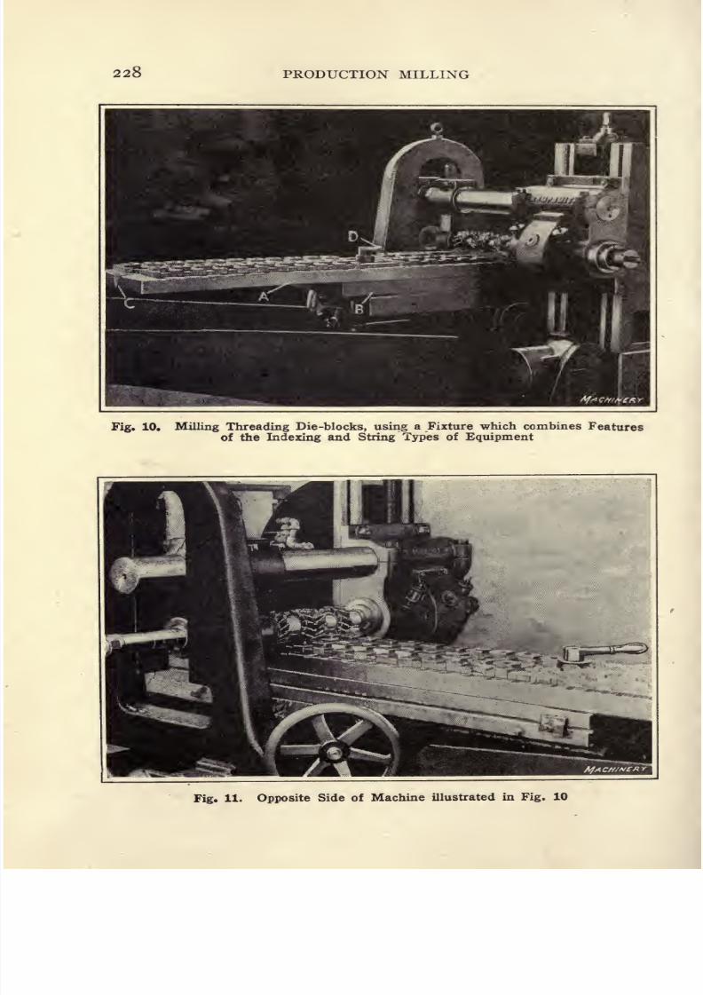
8/13/2019 Production Milling
http://slidepdf.com/reader/full/production-milling 242/296
228 PRODUCTION MILLING
Fig. 10. Milling Threading Die-blocks, using a Fixture which combines Features
of the Indexing and String Types of Equipment
Fig. 11. Opposite Side of Machine illustrated in Fig. 10

8/13/2019 Production Milling
http://slidepdf.com/reader/full/production-milling 243/296
INDEXING FIXTURES 229
that fits over the square end of the screw. After the work
has been secured in the collets, the first of the square sides is
milled. Then the milling machine table is backed away, and
index lever D is turned through one revolution. This motion
is carried to the collets by spur gears having a ratio of i to
4, so that one complete turn of handle D rotates the work
through 90 degrees. The collets are then locked in this posi-
tion and the second of the square sides is milled. By repeat-
ing this indexing and milling operation four times, the square
ends of the punches are completely formed.
Crank handle E clamps the collets for each successive opera-
tion. This handle is secured at the top of the screw F}which
passes through a hole in one end of bar G. At the opposite
end, this bar is held by a bolt H. Bar G is supported by a
fulcrum / formed by the top of a sliding block, the under side
of which bears against the top of the central one of the five
collets. At the lower end of bolt F there is a shoe / which
engages the under sides of two other collets, and a similar
shoe K at the opposite end of the fixture engages the under
side of the two remaining collets. Turning crank handle Eresults in screwing the threaded hub of this handle down on
bolt F, causing bar G to swing on its fulcrum, and, as pressure
is exerted, shoe / is pulled up between two of the collets, thus
locking them in place. Similarly, downward pressure is pro-
vided on shoe /for
locking the third collet, and the tendencyfor bar G to swing over this fulcrum causes shoe K to be drawn
upward, thus locking the two remaining collets.
Indexing Type of String Fixture. At the plant of the
Armstrong Mfg. Co., Bridgeport, Conn., Kempsmith No. 33
Lincoln-type milling machines are used for face-milling blanks
for pipe-threading dies. One of these machines is shown in
Figs. 10 and n, which illustrate opposite sides. These illus-
trations show that the miller is provided with a rather unusual
type of work-holding fixture, which combines features of the
so-called string and
indexing types. In other words,
this tool consists of two stations, on each of which there are
mounted clamps for holding four strings of pieces to be milled.

8/13/2019 Production Milling
http://slidepdf.com/reader/full/production-milling 244/296
230 PRODUCTION MILLING
The fixture is mounted on a pivot, and while pieces set up in
one station are being milled, the operator has ample time to
unload the milled parts from the other station and substitute
fresh blanks. The four plain milling cutters used for this
operation are set up on the arbor with the spiral angles of the
teeth opposed to each other, the purpose being to have these
four cutters arranged in opposed pairs to neutralize the end
thrust.
In designing a fixture of this type, the main table A, on
which the workis
mounted, is carried by a pivot mounted inan intermediate plate B, which is secured to the table of the
milling machine. At the left-hand end of the table, there will
be seen a notch C, and there is a similar notch at the right-hand
end. This is the locating point for the tapered index-pin which
locates the1
fixture in either of the two positions in which it
is used. After indexing, the table must be clamped by a binder
manipulated by lever D. In this operation, the cutters are
driven at a speed of 56 feet per minute, and the work is fed
to the cutters at a rate of 3^ inches per minute. The material
being milled is carbon tool steel.
Indexing Fixture for Face-milling Connecting-rods. The
No. 3 plain Kempsmith milling machine illustrated in Fig. 12
is used by the Holt Mfg. Co., of Peoria, 111., for straddle-milling
both ends of connecting-rod forgings. As the bearings to be
faced are of different widths at opposite ends of the work,
a choice had to be made between resetting the work for the
second milling operation, or indexing the fixture in order to
reach the opposite ends of the forgings. The latter plan was
adopted, and in order to secure constant operation of all of
the four pairs of milling cutters, the fixture was designed to
hold two forgings, with their small ends facing the cutters,
and two other forgings with their large ends facing the cutters.
With this arrangement, the ends of four forgings are straddle-
milled simultaneously, after which the fixture is indexed for
milling the opposite ends of the same forgings.
This machine is set up with a fixture at each end of the table
to avoid idle time of the machine while the operator is remov-
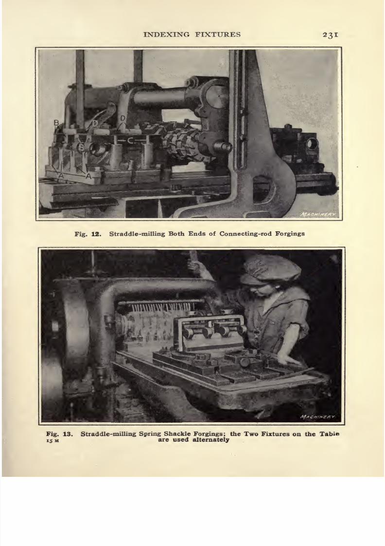
8/13/2019 Production Milling
http://slidepdf.com/reader/full/production-milling 245/296
INDEXING FIXTURES 23 I
Fig. 12. Straddle-milling Both Ends of Connecting-rod Forgings
Fig. 13. Straddle-milling Spring Shackle Forgings; the Two Fixtures on the Table
is M are used alternately

8/13/2019 Production Milling
http://slidepdf.com/reader/full/production-milling 246/296
232 PRODUCTION MILLING
ing milled forgings and reloading the fixture. The sequence
of operations is as follows: First, mill one end of the forgings
held in the left-hand fixture; second, traverse the table over
to mill one end of the forgings held in the right-hand fixture;
third, index the left-hand fixture while pieces held in the right-
hand fixture are being milled, and then traverse the table over
to complete milling the forgings held in the left-hand fixture;
fourth, index the right-hand fixture while the other milling
operation is proceeding, and then traverse table over to com-
plete millingthe
forgingsheld in the
right-handfixture. Dur-
ing the final operation on the forgings held in this fixture,
the completely milled connecting-rods are removed from the
other fixture and fresh forgings are set up. In this way, excel-
lent rates of production may be obtained, as there is prac-
tically no idle time for either the machine or its operator.
On the machine shown in Fig. 12, 400 connecting-rods are
milled in a ten-hour working day.
The forgings are held in this fixture as follows: Each fixture
is provided with four walls A in which transverse V-notches
are cut to receive the bearings at each end of the connecting-
rod, and longitudinal grooves to receive the bolt bosses. After
four rods have been dropped into place, four bars B are placed
on top of them. These bars also have been provided with
longitudinal grooves and transverse V-notches to conform
with the contour of work. The necessary sidewise adjustment
of the work (longitudinal adjustment is effected by the V-blocks
in which the work is carried) is accomplished by having pins C
engage the finished sides of bars B. When the rods have been
properly located, four straps D are tightened, to hold down the
bars B and the connecting-rods secured by them. The machine
operator has ample time to remove the milled forgings and
substitute fresh parts while the remaining operation is being
performed on parts held in the opposite station of the fixture.
Milling Spring Shackle Forgings. At the plant of the
National Motor Car & Vehicle Corporation, Indianapolis,
Ind., use is made of Gooley & Edlund horizontal milling ma-
chines, which are equipped as shown in Fig. 13 for use in mill-
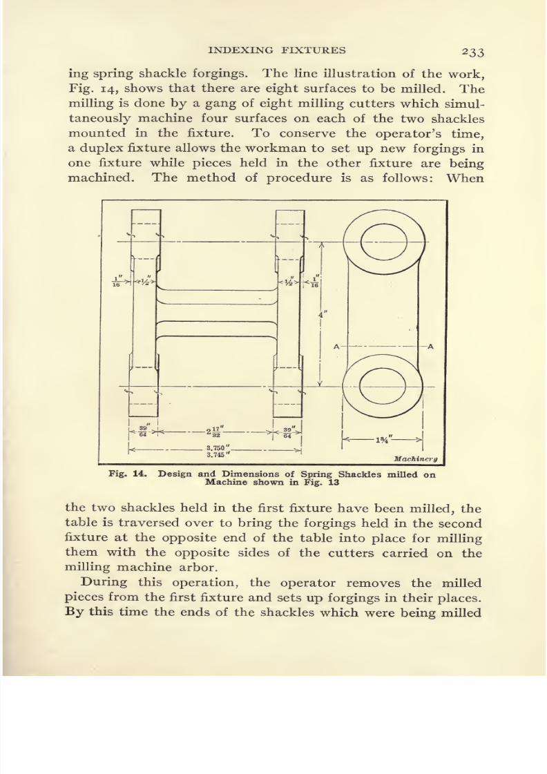
8/13/2019 Production Milling
http://slidepdf.com/reader/full/production-milling 247/296
INDEXING FIXTURES 233
ing spring shackle forgings. The line illustration of the work,
Fig. 14, shows that there are eight surfaces to be milled. The
millingis
done by a gang of eight milling cutters which simul-
taneously machine four surfaces on each of the two shackles
mounted in the fixture. To conserve the operator's time,
a duplex fixture allows the workman to set up new forgings in
one fixture while pieces held in the other fixture are being
machined. The method of procedure is as follows: When
Machinery
Fig. 14. Design and Dimensions of Spring Shackles milled onMachine shown in Fig. 13
the two shackles held in the first fixture have been milled, the
table is traversed over to bring the forgings held in the second
fixture at the opposite end of the table into place for milling
them with the opposite sides of the cutters carried on the
milling machine arbor.
During this operation, the operator removes the milled
pieces from the first fixture and sets up forgings in their places.
By this time the ends of the shackles which were being milled

8/13/2019 Production Milling
http://slidepdf.com/reader/full/production-milling 248/296
234 PRODUCTION MILLING
will have been machined and the table may be traversed over
to perform the first step of the milling operation on pieces held
in the first fixture. During this operation, the operator indexes
the second fixture through an angle of 180 degrees to bring
the opposite ends of the forgings into position for milling.
The next step will be to traverse the table to bring these pieces
into position for the final operation, and while this machining
is in progress the first fixture will be indexed ready to complete
milling the pieces carried in it. The cycle of operations will
Fig. 15. Milling Machine equipped for straddle-milling the Flats
on Hexagon Heads of Spark Plugs
be finished by feeding these forgings up to the milling cutters,
after which the finished spring shackles will be removed from
the second fixture.
This operation is performed with cutters 6 inches in diameter,
which run at a speed of 40 revolutions per minute. Quick
traverse brings the work into position for milling, after which
a feed of i inch per minute is employed for the actual machin-
ing. Each milling cutter is required to face off a round sur-
face on the spring shackles which is if inches in diameter, and
approximately ^ inch of stock is removed from each face.
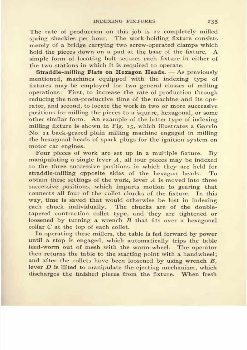
8/13/2019 Production Milling
http://slidepdf.com/reader/full/production-milling 249/296
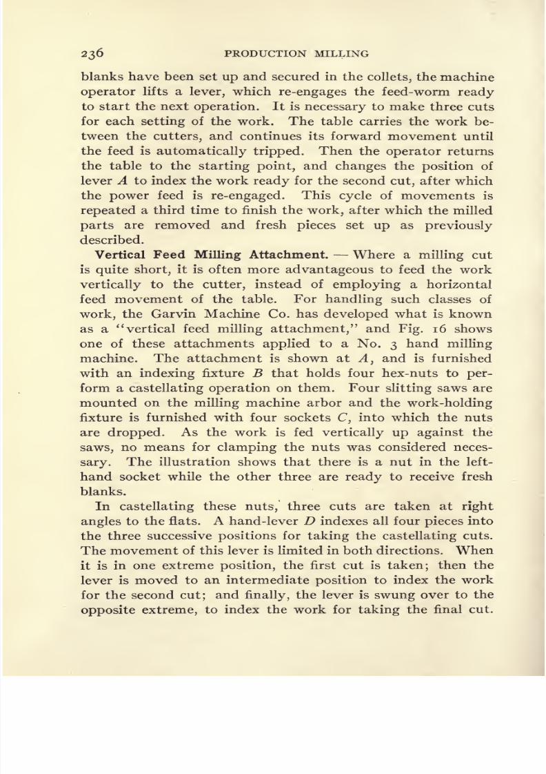
8/13/2019 Production Milling
http://slidepdf.com/reader/full/production-milling 250/296
236 PRODUCTION MILLING
blanks have been set up and secured in the collets, the machine
operator lifts a lever, which re-engages the feed-worm ready
to start the next operation. It is necessary to make three cuts
for each setting of the work. The table carries the work be-
tween the cutters, and continues its forward movement until
the feed is automatically tripped. Then the operator returns
the table to the starting point, and changes the position of
lever A to index the work ready for the second cut, after which
the power feed is re-engaged. This cycle of movements is
repeateda third time to finish the
work,after
which themilled
parts are removed and fresh pieces set up as previously
described.
Vertical Feed Milling Attachment. Where a milling cut
is quite short, it is often more advantageous to feed the work
vertically to the cutter, instead of employing a horizontal
feed movement of the table. For handling such classes of
work, the Garvin Machine Co. has developed what is known
as a vertical feed milling attachment, and Fig. 16 shows
one of these attachments applied to a No. 3 hand milling
machine. The attachment is shown at A, and is furnished
with an indexing fixture B that holds four hex-nuts to per-
form a castellating operation on them. Four slitting saws are
mounted on the milling machine arbor and the work-holding
fixture is furnished with four sockets C, into which the nuts
are dropped. As the work is fed vertically up against the
saws, no means for clamping the nuts was considered neces-
sary. The illustration shows that there is a nut in the left-
hand socket while the other three are ready to receive fresh
blanks.
In castellating these nuts, three cuts are taken at right
angles to the flats. A hand-lever D indexes all four pieces into
the three successive positions for taking the castellating cuts.
The movement of this lever is limited in both directions. When
it is in one extreme position, the first cut is taken; then the
lever is moved to an intermediate position to index the work
for the second cut; and finally, the lever is swung over to the
opposite extreme, to index the work for taking the final cut.
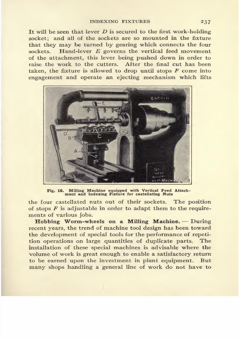
8/13/2019 Production Milling
http://slidepdf.com/reader/full/production-milling 251/296
INDEXING FIXTURES 237
It will be seen that lever D is secured to the first work-holding
socket; and all of the sockets are so mounted in the fixture
that they maybe turned
by gearingwhich connects the four
sockets. Hand-lever E governs the vertical feed movement
of the attachment, this lever being pushed down in order to
raise the work to the cutters. After the final cut has been
taken, the fixture is allowed to drop until stops F come into
engagement and operate an ejecting mechanism which lifts
Fig. 16. Milling Machine equipped with Vertical Feed Attach-
ment and Indexing Fixture for castellating Nuts
the four castellated nuts out of their sockets. The position
of stops F is adjustable in order to adapt them to the require-
ments of various jobs.
Robbing Worm-wheels on a Milling Machine. During
recent years, the trend of machine tool design has been toward
the development of special tools for the performance of repeti-
tion operations on large quantities of duplicate parts. The
installation of these special machines is advisable where the
volume of work is great enough to enable a satisfactory return
to be earned upon the investment in plant equipment. But
many shops handling a general line of work do not have to
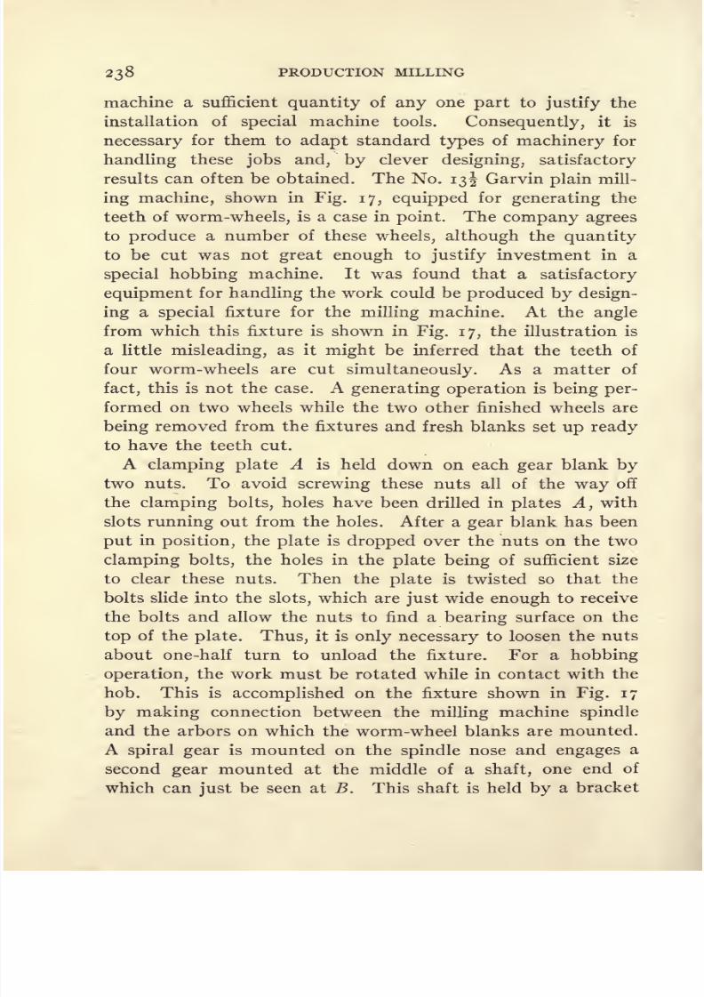
8/13/2019 Production Milling
http://slidepdf.com/reader/full/production-milling 252/296
238 PRODUCTION MILLING
machine a sufficient quantity of any one part to justify the
installation of special machine tools. Consequently, it is
necessary for them to adapt standard types of machinery for
handling these jobs and, by clever designing, satisfactory
results can often be obtained. The No. 13 Garvin plain mill-
ing machine, shown in Fig. 17, equipped for generating the
teeth of worm-wheels, is a case in point. The company agrees
to produce a number of these wheels, although the quantity
to be cut was not great enough to justify investment in a
special hobbing machine. It was found that a satisfactory
equipment for handling the work could be produced by design-
ing a special fixture for the milling machine. At the angle
from which this fixture is shown in Fig. 17, the illustration is
a little misleading, as it might be inferred that the teeth of
four worm-wheels are cut simultaneously. As a matter of
fact, this is not the case. A generating operation is being per-
formed on two wheels while the two other finished wheels are
being removed from the fixtures and fresh blanks set up ready
to have the teeth cut.
A clamping plate A is held down on each gear blank by
two nuts. To avoid screwing these nuts all of the way off
the clamping bolts, holes have been drilled in plates A, with
slots running out from the holes. After a gear blank has been
put in position, the plate is dropped over the nuts on the two
clamping bolts, the holes in the plate being of sufficient size
to clear these nuts. Then the plate is twisted so that the
bolts slide into the slots, which are just wide enough to receive
the bolts and allow the nuts to find a bearing surface on the
top of the plate. Thus, it is only necessary to loosen the nuts
about one-half turn to unload the fixture. For a hobbing
operation, the work must be rotated while in contact with the
hob. This is accomplished on the fixture shown in Fig. 17
by making connection between the milling machine spindle
and the arbors on which the worm-wheel blanks are mounted.
A spiral gear is mounted on the spindle nose and engages a
second gear mounted at the middle of a shaft, one end of
which can just be seen at B. This shaft is held by a bracket

8/13/2019 Production Milling
http://slidepdf.com/reader/full/production-milling 253/296
INDEXING FIXTURES 239
secured to the bed of the milling machine, and the fixture is
free to slide lengthwise on the shaft, which rotates but does
not haveany longitudinal
movement.
An explanation has already been given of the way in which
two wheels are being hobbed while the other two are in the
idle position, so that the finished wheels may be removed and
fresh blanks set up in the fixture. To stop rotation of the
finished work two clutches on shaft B transmit power to the
cross-shafts that drive the two pairs of work-holding arbors.
When the table is moved over to bring two new blanks into
contact with the hobs, one clutch .moves out of engagement
with the cross-shaft through which power is transmitted to
the arbors on which the two finished worm-wheels are mounted.
Fig. 17. Milling Machine equipped with Hobbing Fixtures
At the same time, the other clutch comes into engagementwith the cross-shaft that transmits power to the arbors on
which the two fresh gear blanks are carried. In this way,
disengagement and engagement of the drive is automaticwhen the table is moved over by hand to bring two fresh
blanks into the operating position. The worm-wheels to be
hobbed have 48 teeth of 10 diametral pitch, so that they are
4.8 inches in diameter. On this job, the teeth of two worm-
wheels were completely cut every seven minutes.

8/13/2019 Production Milling
http://slidepdf.com/reader/full/production-milling 254/296
240 PRODUCTION MILLING
Hobbing Small Worm-wheels on a Milling Machine.
Another milling machine equipped for nobbing the teeth of
worm-wheels is illustrated in Fig. 18. This is a No. 21 Garvin
plain miller used at the plant of the Frank Mossberg Co.,
Attleboro, Mass., for generating the teeth of small worm-
wheels shown at A. The equipment of the machine for this
job is rather different from the one shown in the preceding
illustration. Only one work-holding fixture is mounted on
the table, and a quick-clamping mechanism reduces idle time
of the machineas far as
possible. Asmall
trunnion projects
Fig. 18. Milling Machine equipped for generating the Teethof Small Worm-wheels shown at A
out at each side of the worm-wheels A . These trunnions hold
the work in bushings B, which are bored out to receive the
trunnions. The three upper bushings occupy fixed positions
in the fixture, but the lower bushings have rack teeth cut in
them, which mesh with pinions carried by a cross-shaft. Lever
C is mounted at the end of this cross-shaft, and by pushing
the lever down, the three lower bushings are withdrawn so
that the hobbed worm-wheels may be removed from the
fixture and fresh blanks substituted in their places. During
the hobbing operation, the work is rotated by a shaft D that
takes power from the milling machine spindle through a worm-

8/13/2019 Production Milling
http://slidepdf.com/reader/full/production-milling 255/296
INDEXING FIXTURES 241
wheel and worm. This shaft transmits power to gears con-
tained in case E, which are so arranged that all three spindles
are driven simultaneously from the single source of power.After the fixture has been loaded, lever F is raised to bring
the feed-worm into engagement with the worm-wheel, so that
the work is fed to the cutters until the automatic stop G is
engaged, thus tripping the feed at the time that the bobbing
operation has been completed. The table is then returned
to the starting point by handwheel H.
hi
Fig. 19. Indexing Milling Machine equipped with AutomaticFixture for simultaneously roughing out the Teeth of
Four Bevel Gear Blanks
Roughing out Teeth of Bevel Gear Blanks. Experience
has shown that in operating various types of bevel gear genera-
tors, more satisfactory rates of production can be obtained by
performing the operation in two steps first, roughing outthe teeth, and second, generating the teeth to the required
form. Several types of machines have been developed for use
in roughing out the teeth of bevel gear blanks which are to
be finished on a special generating machine. Figure 19 shows
an automatic machine developed for this purpose. It con-

8/13/2019 Production Milling
http://slidepdf.com/reader/full/production-milling 256/296
242 PRODUCTION MILLING
sists of a Garvin No. 9 indexing miller equipped with a fixture
on which four gear blanks can be mounted. Two rotary gear-
cutters are mounted on the arbor of the milling machine, and
the gear blanks are mounted in two pairs, each pair of blanks
being held on an inclined plane, so that the portions of the
faces in which gear teeth are to be cut are held in a horizontal
position. Each pair of gear blanks can thus be fed under one
of the cutters for milling a tooth space in each of the blanks.
After this has been done, the direction of table movement is
Fig. 20. Plain Milling Machine equipped with Three Sets of
Special Single Dial Index-centers for fluting Forgings
automatically reversed and the table is returned to the start-
ing point at high speed. Next, each of the four gear blanks
is automatically indexed through one 'tooth space; then the
forward feed movement of the table is again automatically
engaged to move the work forward for cutting the next tooth
space in each of the blanks. With such an arrangement, it
is only necessary for the operator to set the blanks up on the
machine, after which the work requires no further attention
until all of the teeth have been cut. On this job, the work is
fed to the cutters at a rate of 9 inches per minute, and there

8/13/2019 Production Milling
http://slidepdf.com/reader/full/production-milling 257/296
INDEXING FIXTURES 243
are 40 teeth to be cut in gears having a face width of i^ inches.
The machine completes the operation in 13 minutes, 20 seconds.
Milling Grooves in Steel Forgings. Figure 20 shows a
Brown & Sharpe No. 56 heavy-duty plain milling machine
equipped with three sets of index-centers for milling two grooves
in six steel forgings at each traverse of the table. The grooves
are each 1.17 inches wide by T5 inch deep, and two forgings
are mounted on the arbor between each pair of index-centers.
The cutters are formed in such a way that they mill two
Fig. 21. Universal Milling Machine equipped with Indexing Fixtures for
cutting the Teeth in Milling Cutters
grooves and also finish the top of the raised portion of the
work between two adjacent grooves. After the cut has been
completed, the table is returned to the starting point and the
work is indexed ready for taking the next cut. For this excep-
tionally heavy job, an arbor possessing ample strength must be
used; otherwise, there would be a tendency for the arbor to
spring. To avoid this, the cutter-arbor, which is of consider-
able length, is rigidly supported from the over-arm of the

8/13/2019 Production Milling
http://slidepdf.com/reader/full/production-milling 258/296
244 PRODUCTION MILLING
machine by two intermediate yokes placed between the cut-
ters. The cutters and work are lubricated with lard oil to
prevent them from becoming overheated.
Fluting Hollow-milling Cutters. There are many examples
of tool-room work, such as the fluting of various types of
cutting tools, where it is necessary to produce a number of
pieces of a standard form. For such jobs, the use of an index-
ing milling fixture will often greatly increase rates of produc-
tion. Figure 21 shows a universal milling machine which is
equippedwith an
indexingfixture for
simultaneously flutingtwo hollow-milling cutters. The cutter blanks A are held in
collet chucks, and two angular milling cutters B are mounted
on the arbor of the machine. To save as much time as possi-
ble in indexing the work for taking successive cuts, an index-
plate C is mounted at the rear end of one of the work-spindles,
this plate being notched to receive an index-pin which locates
the cutter blank held by the fixture in position for milling. A
pair of spur gears D connects the spindles of the two fixtures,
so that when the spindle that carries the index-plate is turned
through the required angle to bring the work into position for
taking the next cut, the piece of work carried by the other
spindle is simultaneously located. The angular milling cutters
B are made of high-speed steel, and on this job the cutters
were driven at 81 revolutions per minute, which corresponds
to a cutting speed of 63.6 feet per minute; and the work is
fed to the cutters at 2.15 inches per minute.
8/13/2019 Production Milling
http://slidepdf.com/reader/full/production-milling 259/296
CHAPTER VIII
OPERATIONS ON MACHINES OF RECIPROCATING TYPE
MANUFACTURERS who have had experience in the operation
of milling machines for the quantity production of duplicate
parts, or in designing work-holding fixtures for use on milling
machines employed in this class of service, are familiar with the
so-called multiple-spindle or planer type of machines built by
the Ingersoll Milling Machine Co. To meet the requirements
of certain classes of work for which the planer-type machine
of large size is not ideally adapted, a number of smaller units
provided with special means for facilitating the milling of dupli-
cate parts have also been developed by this company.
Although these machines are adapted to meet the special
requirements of individual jobs, the building of each machine
does not involve a completely new problem of machine design.
There are certain recognized principles of construction employed
in the various sizes and styles of Ingersoll milling machines.
When a customer submits blueprints of a piece to be machined,
together with data concerning such matters as the amount of
stock to be removed from the different finished surfaces and
the rate of production that is required, it is possible for the
designers to make recommendations for the construction of a
machine of recognized type, the details of which have been
modified to fulfill the peculiar requirements of the work. In
this chapter it is proposed briefly to explain the fundamental
principles of several new types of these milling machines that
have been developed to enable small parts to be milled in
quantities,' with the attainment of a high degree of efficiency
in production and economy of labor, floor space, etc.
Milling Tractor Transmission Housings on Reciprocating
Milling Machines. The name reciprocating milling ma-
chine has been applied to a new machine shown in Figs, i
245

8/13/2019 Production Milling
http://slidepdf.com/reader/full/production-milling 260/296
246 PRODUCTION MILLING
and 2, because the table moves back and forth to provide for
alternately machining castings held by fixtures that are set
up at opposite ends of the table. As the machine was built
to meet the requirements of a special repetition milling opera-
tion on which it is to be used continuously, it will be evident
that no advantage would be secured through providing an
Fig. 1. Reciiprocating Type of Miller, designed and built for
milling Tractor Transmission Housings
expensive mechanism for obtaining the several selective
changes of cutting speed. But it is important to provide
means for quickly reversing the table to bring the second
piece of work into engagement with the cutters, after the
milling operation has been completed on the first piece. For
this reason the machine is designed to feed the work under

8/13/2019 Production Milling
http://slidepdf.com/reader/full/production-milling 261/296
RECIPROCATING TYPE OF MACHINES 247
the cutters at a rate of 4^ inches per minute, and as soon as
the operation on one piece of work has been completed, a fast
power reverse movement is engaged to withdraw the first pieceof work quickly from the cutters. This movement continues
until the work held by the fixture at the opposite end of the
Fig. 2. Opposite Side of Machine illustrated in Fig. 1, showingMethod of locating and clamping Work Ready for milling
table is brought up to the cutters. When this piece of work
has been advanced to the proper point, the fast traverse is
automatically disengaged and the 4^ inches per minute rate
of feed once more becomes operative. It is important to note
that while the work held in one fixture is being milled, the
table is feeding in the opposite direction from that in which
it moves while work held in the other fixture is being milled.
l6M
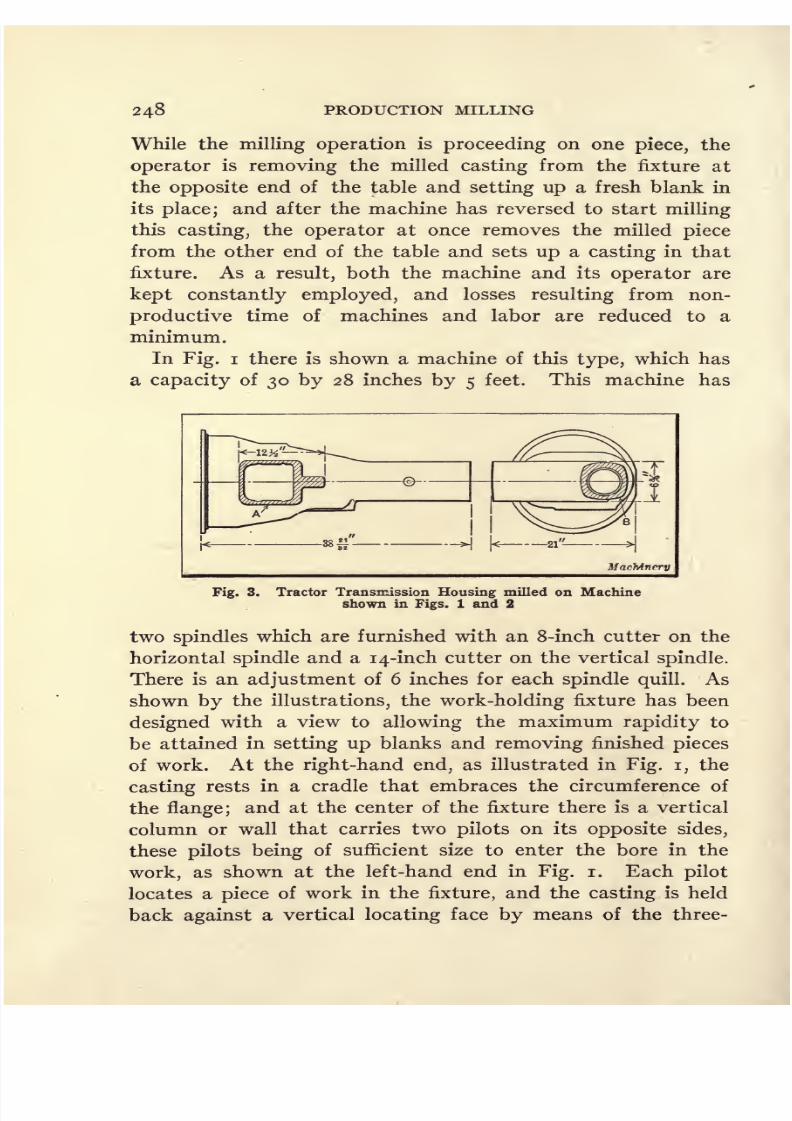
8/13/2019 Production Milling
http://slidepdf.com/reader/full/production-milling 262/296
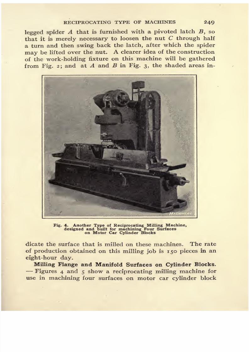
8/13/2019 Production Milling
http://slidepdf.com/reader/full/production-milling 263/296
RECIPROCATING TYPE OF MACHINES 249
legged spider A that is furnished with a pivoted latch,so
that it is merely necessary to loosen the nut C through half
a turn and then swing back the latch, after which the spider
may be lifted over the nut. A clearer idea of the construction
of the work-holding fixture on this machine will be gathered
from Fig. 2; and at A and B in Fig. 3, the shaded areas in-
Fig. 4. Another Type of Reciprocating Milling Machine,
designed and built for machining Four Surfaces
on Motor Car Cylinder Blocks
dicate the surface that is milled on these machines. The rate
of production obtained on this milling job is 150 pieces in an
eight-hour day.
Milling Flange and Manifold Surfaces on Cylinder Blocks.
Figures 4 and 5 show a reciprocating milling machine for
use in machining four surfaces on motor car cylinder block

8/13/2019 Production Milling
http://slidepdf.com/reader/full/production-milling 264/296
25 PRODUCTION MILLING
castings, two settings of the work and two operations being
required for completing the work on each piece. By com-
paring Figs,i and
4,the reader will
gaina
comprehensiveidea of the way in which special machines are built to suit
the requirements of individual jobs, with the incorporation of
the standard principles of design in all machines of a given
Fig. 5. Close-up View of Cutters and Work on the Machineillustrated in Fig. 4, showing Flanged Surface
and Manifold Seat to be milled
type. Superficially,
there is little resemblance between these
two machines, but actually they are both reciprocating milling
machines with two fixtures mounted at opposite ends of the
table and the mechanism arranged to move the table back
and forth, so that the cutters may first mill two surfaces on
one casting and then start work on another casting, after
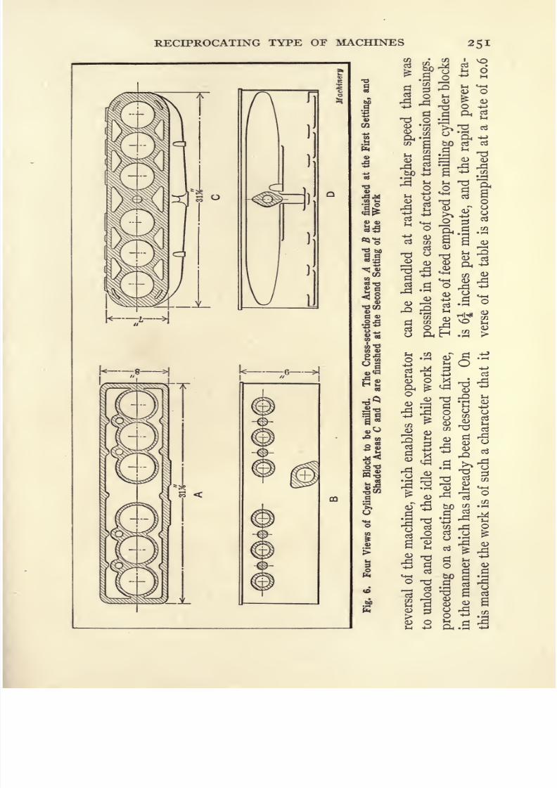
8/13/2019 Production Milling
http://slidepdf.com/reader/full/production-milling 265/296
RECIPROCATING TYPE OF MACHINES
A
L---6
3
I
b-s
l<a-S*^ CD
a o tJ
p2n 4)
.a
-9 o
'S a S
III3 I.S
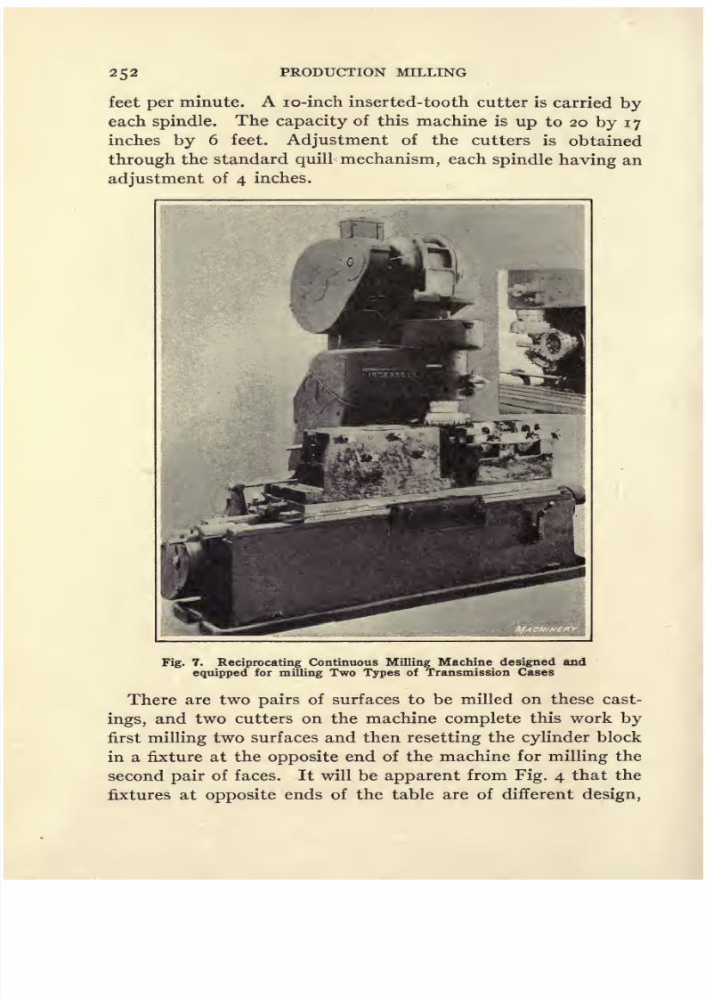
8/13/2019 Production Milling
http://slidepdf.com/reader/full/production-milling 266/296
252 PRODUCTION MILLING
feet per minute. A lo-inch inserted-tooth cutter is carried by
each spindle. The capacity of this machine is up to 20 by 17
inches by6 feet.
Adjustmentof the
cuttersis
obtainedthrough the standard quill mechanism, each spindle having an
adjustment of 4 inches.
Fig. 7. Reciprocating Continuous Milling Machine designed and
equipped for milling Two Types of Transmission Cases
There are two pairs of surfaces to be milled on these cast-
ings, and two cutters on the machine complete this work by
first milling two surfaces and then resetting the cylinder block
in a fixture at the opposite end of the machine for milling the
second pair of faces. It will be apparent from Fig. 4 that the
fixtures at opposite ends of the table are of different design,

8/13/2019 Production Milling
http://slidepdf.com/reader/full/production-milling 267/296

8/13/2019 Production Milling
http://slidepdf.com/reader/full/production-milling 268/296
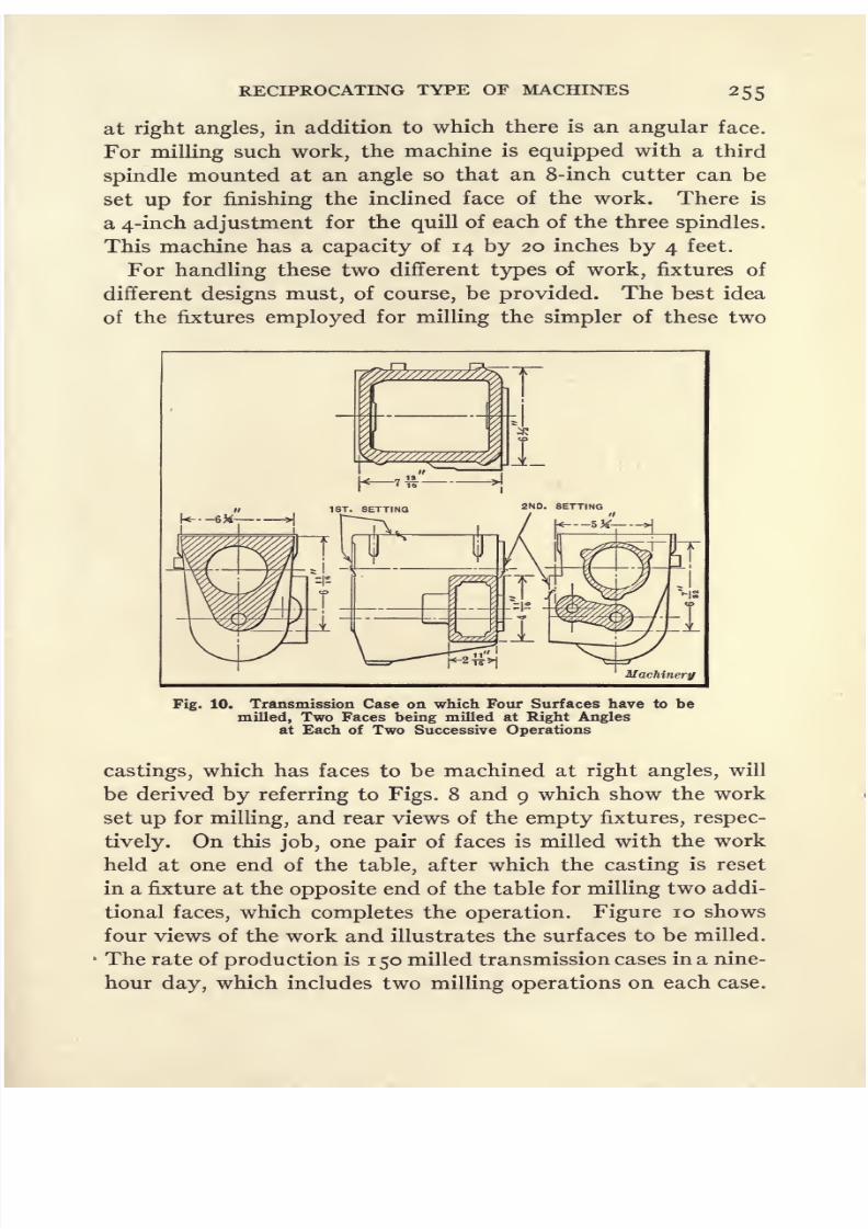
8/13/2019 Production Milling
http://slidepdf.com/reader/full/production-milling 269/296
RECIPROCATING TYPE OF MACHINES 255
at right angles, in addition to which there is an angular face.
For milling such work, the machine is equipped with a third
spindlemounted at an
angleso that an 8-inch cutter can be
set up for finishing the inclined face of the work. There is
a 4-inch adjustment for the quill of each of the three spindles.
This machine has a capacity of 14 by 20 inches by 4 feet.
For handling these two different types of work, fixtures of
different designs must, of course, be provided. The best idea
of the fixtures employed for milling the simpler of these two
Machinery
Fig. 10. Transmission Case on which Four Surfaces have to be
milled, Two Faces being milled at Right Anglesat Each of Two Successive Operations
castings, which has faces to be machined at right angles, will
be derived by referring to Figs. 8 and 9 which show the work
set up for milling, and rear views of the empty fixtures, respec-
tively. On this job, one pair of faces is milled with the work
held at one end of the table, after which the casting is reset
in a fixture at the opposite end of the table for milling two addi-
tional faces, which completes the operation. Figure 10 shows
four views of the work and illustrates the surfaces to be milled.
The rate of production is 1 50 milled transmission cases in a nine-
hour day, which includes two milling operations on each case.

8/13/2019 Production Milling
http://slidepdf.com/reader/full/production-milling 270/296
Fig. 11. Close-up View of Fixture for Transmission Cases
256 Fig. 12. Four-spindle Reciprocating Continuous Milling Machine
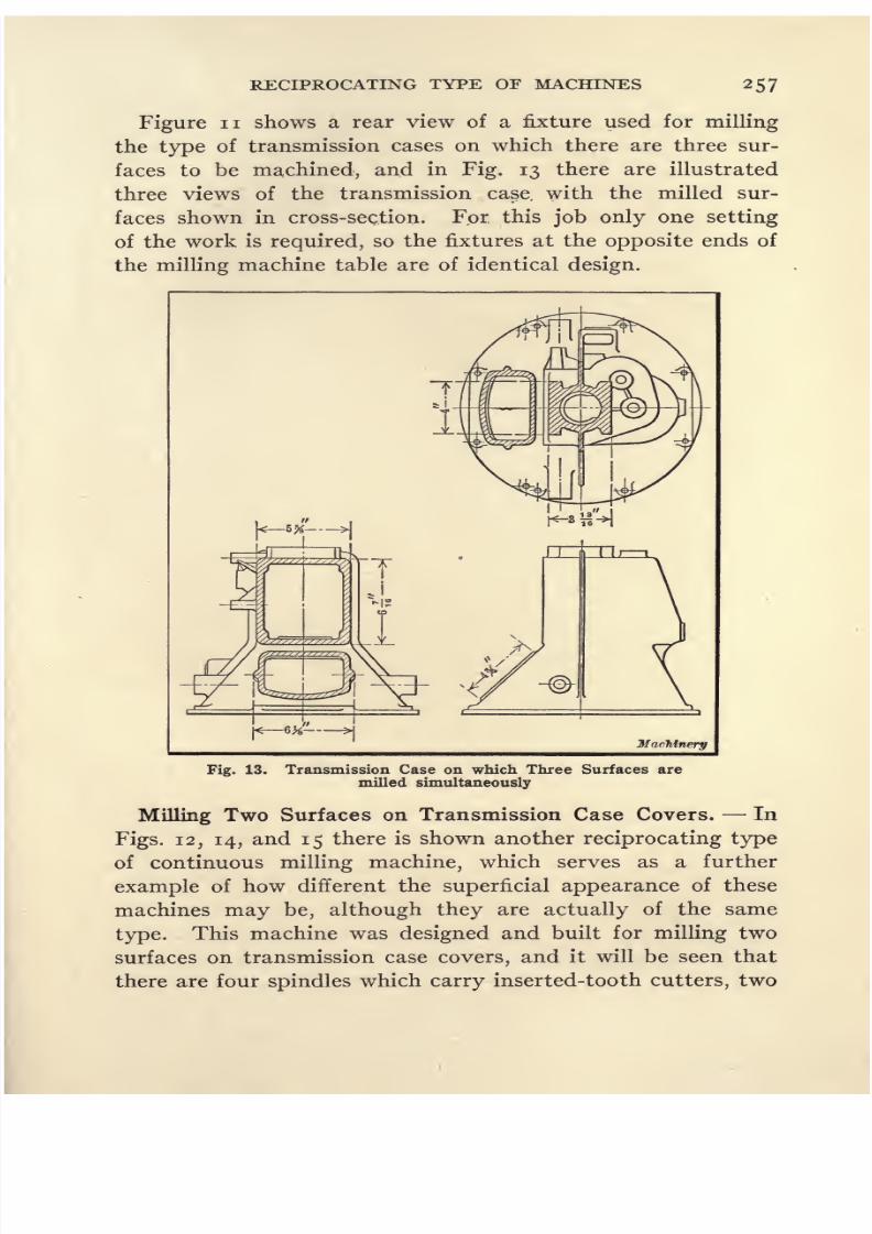
8/13/2019 Production Milling
http://slidepdf.com/reader/full/production-milling 271/296
RECIPROCATING TYPE OF MACHINES 257
Figure n shows a rear view of a fixture used for milling
the type of transmission cases on which there are three sur-
faces to be machined, and in Fig. 13 there are illustrated
three views of the transmission case, with the milled sur-
faces shown in cross-section. For this job only one setting
of the work is required, so the fixtures at the opposite ends of
the milling machine table are of identical design.
>i
Machinery
Fig. 13. Transmission Case on which Three Surfaces are
milled simultaneously
Milling Two Surfaces on Transmission Case Covers. In
Figs. 12, 14, and 15 there is shown another reciprocating type
of continuous milling machine, which serves as a further
example of how different the superficial appearance of these
machines may be, although they are actually of the same
type. This machine was designed and built for milling two
surfaces on transmission case covers, and it will be seen that
there are four spindles which carry inserted-tooth cutters, two

8/13/2019 Production Milling
http://slidepdf.com/reader/full/production-milling 272/296
258 PRODUCTION MILLING
of which operate on the casting held in a fixture at one end of
the table, while the other two cutters operate on work held
by a fixtureat
the opposite end of the table. This form of
machine construction was necessitated by the shape of the
work which has a shoulder, on the ends of which there are faces
Fig. 14. Opposite Side of Four-spindle Reciprocating Type of
Continuous Milling Machine. This Illustration showsthe Second Surface to be milled
to be milled. The overhanging portion of the work wouldinterfere with the cutters in traversing the table unless the
space between the housings of the machine was substantially
widened. This would not only add to the cost of building
the machine, but would also make it take up a greater amount
of floor space. As a result, it was considered a more economical

8/13/2019 Production Milling
http://slidepdf.com/reader/full/production-milling 273/296
RECIPROCATING TYPE OF MACHINES 259
proposition to use the four-spindle design. On this machine
a feed of 6J inches per minute is employed, while the rapid
table traverse is at a rate of 10.6 feet per minute. The cutters
are 4 inches in diameter, and each spindle quill has an adjust-
ment of 2 inches. The capacity of the machine is 14 by 14
Fig. 15. Close-up View of Cutters and Work on Four-spindle
Reciprocating Type of Continuous Milling Machineshown in Figs. 13 and 14
inches by 5 feet. In Fig. 16, the shaded areas show the sur-
faces that are milled at opposite ends of the work.
MillingTiming
Gear Case Covers on Semi-automatic Ma-
chines. In Figs. 17 and 18 there is shown a semi-automatic
milling machine which was built for use in two successive
operations on timing gear case covers, but in this instance the
method of handling the work is essentially different from that
which was employed in the case of cylinder blocks and trans-

8/13/2019 Production Milling
http://slidepdf.com/reader/full/production-milling 274/296
K H
260

8/13/2019 Production Milling
http://slidepdf.com/reader/full/production-milling 275/296
RECIPROCATING TYPE OF MACHINES 261
table is still at rest the operator loads the first fixture, after
which he throws in a feed-lever that starts the table carrying
the work under the cutters at a rate of 6| inches per minute.
As soon as the operator has engaged the feed movement, he
proceeds to load the balance of the fixtures as rapidly as pos-
Fig. 17. Semi-automatic Milling Machine, for performingTwo Operations on Timing Gear Case Covers
sible, the design of the clamping mechanism having been
worked out in such a way that no trouble is experienced in
loading the fixtures more rapidly than the table carries them
under the cutters. After the operator has loaded the last fix-
ture of the string (it will be seen that there are two rows of
fixtures running oarallel along opposite sides of the table),

8/13/2019 Production Milling
http://slidepdf.com/reader/full/production-milling 276/296
262 PRODUCTION MILLING
he goes to the opposite side of the arch and unloads milled
castings which have passed out from under the arch.
When the cutter has cleared the last piece of work, a stop
is engaged to throw out the 6J-mch power feed automatically
and engage a rapid traverse movement which takes place at
Fig. 18. Opposite Side of Machine illustrated in Fig. 17.
this Point in the Table Travel, the Operatorstarts unloading Castings
At
a rate of 10.6 feet per minute. This quickly carries the bal-
ance of the pieces of work out from under the arch, after
which a second stop disengages the fast table movement,
leaving the table at rest. The operator now removes the
balance of the pieces of work from the fixtures, after which he
throws in a return lever to start the table traveling back to the

8/13/2019 Production Milling
http://slidepdf.com/reader/full/production-milling 277/296
RECIPROCATING TYPE OF MACHINES 263
initial position at a rate of 10.6 feet per minute. When the
table reaches the starting position, it stops automatically.
The cycle is then repeated by the operator's putting two cast-
ings in fixtures at opposite sides of the table and re-engaging the
forward feed movement, after which he proceeds to reload
the balance of the fixtures and go through the other move-
ments of the cycle that have just been described. It will be
Machinery
Fig. 19. Two Views of the Timing Gear Covers, where Cross-
sectioned Areas show Surfaces to be milled
seen that on each of the timing gear case covers milled on
this machine, there are two surfaces to be milled at the first
operation. Four spindles enable these two surfaces on each
casting in the two rows carried at opposite sides of the table
to be simultaneously milled as they are carried under the archof the machine. After the work has been completed on this
machine, the castings are sent to a second machine on which
another milling operation is employed. Figure 19 shows the
two shaded areas A and B that are milled on the machine shown
in Figs. 17 and 18.
I? M

8/13/2019 Production Milling
http://slidepdf.com/reader/full/production-milling 278/296
CHAPTER IX
ECONOMY IN MILLING OPERATIONS
THERE are four factors, known as the equipment factor, the
direct labor cost factor, the tool cost factor, and the quality
factor, each of which affects the final manufacturing cost of
milling operations. In order to obtain the maximum economy,
careful consideration must be given to the importance of each
of these factors for the conditions under which any milling
operation is performed. This is one of the numerous cases
where scientific management is merely an application of
common-sense methods of procedure in deciding upon the
most satisfactory procedure in handling industrial work. A
study should be made of the way in which each factor that
affects milling economy will increase or reduce the final cost
of the work, and the method of operating milling machines
must then be so arranged that the most advantageous com-
bination of results will be secured. It will frequently happen
that where the most satisfactory method is employed, one or
more factors will tend to increase the cost of manufacture,
but this will be more than offset by the reduction effected
through the influence of other factors. In this chapter, a brief
outline will be presented of conditions which were discovered
during an investigation of the efficiency of methods used for
milling operations in a plant engaged in the manufacture of
small arms. These data are presented as an illustration of
the effect of the different milling factors upon production
costs; they also show the tendency toward economy that
is made possible through handling work in large quantities.
This discussion is merely presented to assist the reader in
drawing general conclusions in regard to the most satisfactory
methods of operating milling machines. Detailed informa-
264

8/13/2019 Production Milling
http://slidepdf.com/reader/full/production-milling 279/296
ECONOMY IN MILLING 265
tion concerning the milling of rifle parts would be of value to
only a small number of readers.
The EquipmentFactor.
Itemsof
manufacturing expenseresulting from the factor of machines and equipment include
the initial cost of the machinery, the cost of maintenance, loss
through depreciation, interest on the investment, cost of
power, rent for factory floor space, etc. A reduction of the
amount of equipment used to produce a given quantity of
work will naturally result in a material decrease in the items
of expense resulting from this factor. There are two possible
conditions, however, that must be considered in regard to the
equipment factor, before it is possible to determine definitely
the most economical method of milling. First, if there is
plenty of equipment and factory space available, which would
otherwise remain idle, there would be no economy in utiliz-
ing only a small part ofit,
if so doing would terid to increase
the items of expense resulting from some of the other factors
which affect the final cost of manufacturing. Second, if it is
necessary to provide new equipment, the saving effected by
using a minimum amount of equipment should be carefully
balanced against the increased expense resulting from the
other factors under such conditions. The least expensive
total would be the cheapest method, regardless of the separate
items of expense resulting from the individual factors.
There are three possible methods of procedure in operating
milling machines with a view to obtaining the maximum
economy in manufacturing costs. The first method is to
require each operator to run a large number of machines,
the object being to keep the men busy, even if this entails
more or less idle time for a part of the machinery placed in
their charge. The second method is to time-study the indi-
vidualoperations carefully and
soarrange the work that the
machines are kept constantly employed and lost time of the
operators is reduced to a minimum for such working condi-
tions. If there is any preference between these two methods
it is probably in favor of keeping the machines busy, even if
this should result in a slightly higher proportion of idle time

8/13/2019 Production Milling
http://slidepdf.com/reader/full/production-milling 280/296

8/13/2019 Production Milling
http://slidepdf.com/reader/full/production-milling 281/296
ECONOMY IN MILLING 267
Figure i presents in graphical form the same data that appear
in Table i. From this illustration it will be noted that several
of the curves cross each other at the start,this
being dueto
the imperfect method of grouping the various operations.
8
FIRST METHOD
FIRST METHOD(CORRECTED)
SECOND METHOD
THIRD METHOD
X
XxX
XX
X
PRODUCTION OF RIFLES PER DAY
Machinery
ates ofig. 1. Diagrams showing Equipment Factors for Various Daily RProduction
A corrected curve is also presented, to indicate what would be
the tendency with the first method, if the operations were
grouped under the more advantageous conditions.
The Direct Labor Cost Factor. There appears to be prac-
tically no change in the average piece price per milling opera-

8/13/2019 Production Milling
http://slidepdf.com/reader/full/production-milling 282/296
268 PRODUCTION MILLING
tion where the first, second, or third method of milling is used.
That this factor should remain constant is to be expected, be-
cause it will be evident the work of men employed to operate
automatic milling machines consists of unloading and reload-
ing the work-holding fixtures, and starting the machines.
This work is practically constant, regardless of whether a man
handles his quota of pieces on one machine or on a number of
machines placed in his charge.
The Cutter Cost Factor. Another factor that must receive
considerationin
determining the most economical method of
milling is the question of cutter cost. On some classes of mill-
ing operations, where the cutter cost is very low, this factor
does not have an important effect upon manufacturing costs;
but where expensive formed cutters are required, the influence
of this factor becomes a matter of vital importance. As the
cutting speed is increased, with a corresponding increase in
the rate of feed, the machine hour time of the operation is
correspondingly reduced. But under these new operating
conditions, there is also a marked reduction of the number of
pieces that each cutter will mill before it is worn out. If it
is estimated that an average cutter should be reground twenty-
five times before it is worn out, the total cutter cost may be
readily obtained by adding the expense of resharpening to the
original cost of the tool. With this information available,
it is easy to calculate the number of pieces milled by the cutter,
and the cutter cost per piece. It is a matter of general knowl-
edge that the number of pieces that can be machined by a tool
during its operating life will be increased by reducing the cut-
ting speed and feed;and there will be a corresponding decrease
in the cutter cost factor where such a procedure is adopted.
It is evident, however, that the economy secured through
following such a course is offset by the increase in expenseitems resulting from the equipment factor. Hence, it is a
question of carefully regulating the cutting speed so that the
most advantageous balance of these two factors will be secured.
Table 2 presents the results of an investigation of. how the
cutter cost factor affected the cost of performing milling opera-

8/13/2019 Production Milling
http://slidepdf.com/reader/full/production-milling 283/296
ECONOMY IN MILLING 269
tions in the small arms plant. These figures are for machines
operated according to the third method of milling. It will be
seen from this table that the cutting speed is from 70 to 80
feet per minute. The cutting speed of machines operated
according to the first method of milling was from 30 to 40
feet per minute. Probably the average cutter cost per 100
pieces milled on machines operated according to the third
method is more than four times as great as the cutter cost of
Table 2. Data Showing Influence of Cutter Cost Factor on Manu-
facturing Expense
Surface
Speed,Feet
Minute

8/13/2019 Production Milling
http://slidepdf.com/reader/full/production-milling 284/296
27 PRODUCTION MILLING
five times the amounts specified in the second and third col-
umns of Table 2. Figure 2 shows, in graphic form, the data
relative to the life of milling cutters which are presented in
Table 2. This chart shows that there is a decided difference
between the life of cutters engaged in the performance of
rough-milling operations and of finish-milling operations. As
85
80
75
o 70
65
60
SHORT ROUGHING CUT
MEDIUM ROUGHING CUT
LONG ROUGHING CUT
SHORT FINISHING CUT^-MEDIUM FINISHING CUT
LONG FINISHING CUT
NUMBER OF INCHES MILLED BETWEEN GRINDINGS
Machinery
Fig. 2. Diagram showing Effect of Cutting Speed on Durability of MillingCutters for Roughing and Finishing Cuts
the type of cutter used also has an important effect on the
amount of work produced, it is necessary to determine the most
economical cutting speed for each individual type of cutters.
The Quality Factor. The factor governing the quality of
workmanship is, in the final analysis, the controlling factor on
any job where the product is required to come up to a high
standard. The quality of workmanship may be overlooked
in performing machining operations, but sooner or later this
neglect must be paid for, either by damaging the firm's repu-
tation, by performing additional operations to correct errors

8/13/2019 Production Milling
http://slidepdf.com/reader/full/production-milling 285/296
ECONOMY IN MILLING 271
in dimensions, or by actually scrapping those parts which
cannot be made to pass inspection. It is difficult to place a
cash value on the quality of workmanship factor, because it
is hard to put a trustworthy valuation on a firm's reputation.
This factor is partially dependent upon cutting speeds and
feeds at which milling operations are performed. On work
which was milled in this small arms plant according to the
third method of procedure, the amount of scrap ranged from
7 to 66 per cent, with an average of over 20 per cent, which
was entirely too high. Ten per cent should more than cover
this item. This high percentage of scrap was due to many
causes, among which may be mentioned the necessity of
employing unskilled operatives and of forcing machines be-
yond their normal productive capacity. The machine ad-
juster stated that new arbors on these machines would be
bent sufficiently to cause them to take a permanent set, after
being in service for two days. Such conditions are certainlynot conducive to the production of work of good quality.
Many filing and fitting operations were required after the
machining had been finished, in order to have the work meet
all requirements. There are always a considerable number
of burring and cornering operations to be performed by hand,
but an excessive, amount of this work represents a needless
labor cost against the job. On rifle parts milled
according
to
the third method, this investigation showed that the filing
cost per hundred pieces was $0.233.
Reference to Table 2 will show that the variations from
the specified size of those parts which come closest to the
required dimension is 0.006 inch, and that the error ranges
from that amount up to 0.030 inch. With such wide varia-
tions from specified dimensions, the cost of filing the work is
bound to be too high. A toolmaker can easily hold milled
work within a limit of 0.002 inch, without any special facili-
ties of the nature that are usually provided on manufacturing
jobs. With these special means for locating and holding the
work, it would not be unreasonable to expect milled parts to
come within 0.002 and 0.003 inch. Where such a degree of
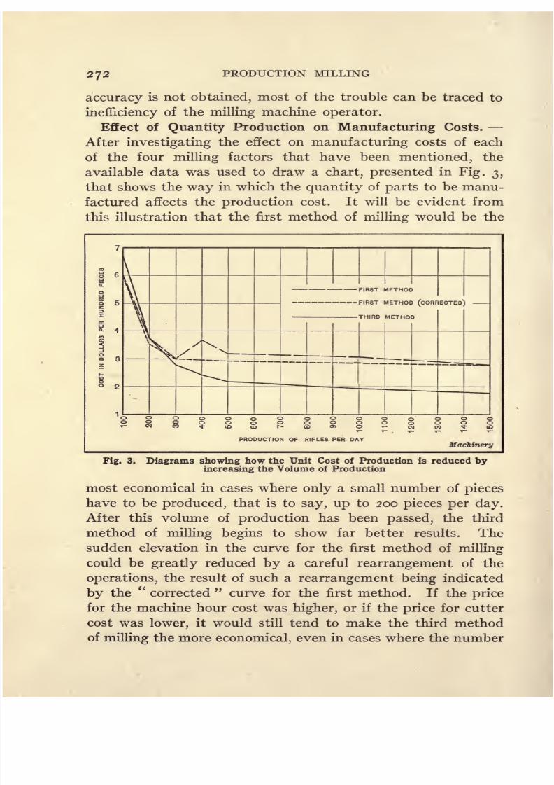
8/13/2019 Production Milling
http://slidepdf.com/reader/full/production-milling 286/296

8/13/2019 Production Milling
http://slidepdf.com/reader/full/production-milling 287/296
ECONOMY IN MILLING 273
of parts to be produced is less than 200 per day. But if these
conditions were reversed, the first method of milling would
tend to become the more economical, in cases where large
numbers of parts have to be produced.
Certain factors show desirable results when using one
method of milling, while other factors will reduce costs where
some other method of milling is employed. In every case,
the aim should be to adopt that method which will give the
most economical results. For example, Fig. 3 shows that the
third method of
milling
is more economical for aproduction
of over 300 rifles per day, although the cutter cost, the expense
offiling,
and the loss of scrapped work, have all been increased.
In adopting the third method, an effort should be made to
reduce the filing cost and scrap loss as far as possible. In this
particular case, the cutter cost probably cannot be brought
down much lower. These figures would tend to show that the
application of high cutting speeds is the more economical plan,
where large quantities of work are to be produced; but all
operations involving the use of expensive formed cutters
should be performed in a way that will save the cutter as far
as possible.
After the minimum number of machines necessary to pro-
duce the required number of parts has been determined, the
speed and feed should be so selected that they will not only
give the necessary output of milled parts, but will also afford
an economical balance between the items of expense resulting
from the equipment and cutter cost factors. For example, if
one machine is able to perform 400 milling operations a day,
and it is required to perform this operation on 600 pieces a
day, it will be evident that two machines are necessary. Both
of these millers will be tied up on this job, and nothing would
be saved by running them at top speed for three fourths of
the day and then having them idle for the remaining 25 per
cent of the time. It will be possible, however, to effect a
material saving in the cutter cost by slowing down both of
the machines to produce 300 pieces a day, and have them in
operation for the full ten-hour working period.

8/13/2019 Production Milling
http://slidepdf.com/reader/full/production-milling 288/296

8/13/2019 Production Milling
http://slidepdf.com/reader/full/production-milling 289/296
INDEX
PAGE
Aluminum crankcases, milling 105
Anchor-clips, straddle-milling 58
Automatic machines, circular feed movement 3
feed movements 9
production milling on 9
straight-line feed movement 3Automobile crankcases, milling 136, 144
milling ends of 146
Automobile plants, planer-milling in 130
Automobile self-starters, milling generator frames for 208
Bearing blocks, main, for tractor engine, machining 86
Bearing caps, milling 127
Bevel gear blanks, cross-slotting 61
roughing out teeth of 241
rough-milling teeth of 122
Bolt heads, straddle-milling 72
Bomb-container, face-milling bosses on 87
Brake lever, automobile, slot milled in 195
Camshafts, straddle-milling, to length 222
Castings, supporting, for milling four faces simultaneously 125
thin, adjustable supporting points for 139
Channeling connecting-rods 175Clamps, reducing load on 100
Clutch cutting, duplex fixture for 212
Clutch shaft bearings, milling 112
Clutch shifter forks, milling 184
Clutch shifter yokes, simultaneously milling four faces 109
Connecting-rods, face-milling 230
face-milling on continuous rotary machines 121
facing base of crankpin bearing caps for 24
facing bearings of 14
facing seat for crankpin bearing cap 22
fluting or channeling operations on 175
milling186
milling clearance spaces between bolt bosses of 17, 190
setting up for milling 16
straddle-milling bolt bosses and cutting off bearing caps of 20
Continuous rotary milling 76
275

8/13/2019 Production Milling
http://slidepdf.com/reader/full/production-milling 290/296
276 INDEX
PAGE
Cover plate, milling both sides of noCrankcases, aluminum, face-milling 105
automobile, milling136, 144
automobile, milling ends of 146
Crankpin bearing caps for connecting-rods, facing base of 24
facing seat for 22
Crankshaft bearing caps, face-milling seat of95
milling I96
Cutter cost factor in economy milling 268
Cutters, fluting hollow-milling 244
Cylinder blocks, automobile, milling 150, 156
flange and manifold surfaces, milled on 249
for tractor engines, milling 82
Cylinder heads, face-milling, for tractor engines , 85
for automobiles, milling 166
Differential bearing caps, milling base of 25
Different operations on same part in one fixture 91
Different parts milled in one fixture 89
Dividing head parts, string fixture for milling 210
Economy factors in milling 264
cutter cost 268
direct labor cost 267
equipment 265
Equipment factor in economy milling 265
Fan pulley castings, face-milling 106
Feed movement, automatic machines 9
vertical, attachment for 236
Fixtures, indexing 213, 229
Fluting connecting-rods 175
Fluting hollow-milling cutters 244
Footstocks for spiral heads, milling 199
Gear blanks, bevel, roughing out teeth of 241
bevel, rough-milling teeth in 122
cross-slotting61
Gear-box levers, milling 183
Generator frames for automobile self-starters, milling 208
Grinding machine tables, milling two, simultaneously 201
Guns, back sight bed of, milling 4
back sight leaf, milling 44
back sight leaf slide dog, milling 46
back sight leaf slide, milling 44
8/13/2019 Production Milling
http://slidepdf.com/reader/full/production-milling 291/296
8/13/2019 Production Milling
http://slidepdf.com/reader/full/production-milling 292/296
278 INDEX
PAGE
Side frames, locomotive, slabbing operations on 171
Side-rods, locomotive, slabbing operations on 178
Slabbing operations, on locomotive side-frames 171on locomotive side-rods 178
Slots, milled in non-parallel sides 48
milled in tabular typewriter rods 206
milled in typewriter carriage roll guides 203
Spring shackle forgings, milling 232
Spring shackles, milling six surfaces on 113
Steel forgings, grooves milled in 243
String fixtures, indexing type of 229
String milling fixtures 182
Tappet valves, straddle-milling shanks of 97
Thin castings, adjustable supporting points for 139
Three-point suspension principle 133
Tilted Rotary machines 52
Timing gear case covers, milled on semi-automatic machines 259
Transmission case covers, milling two surfaces on 257
Transmission cases, milling operations on two types of 254
Transmission housings, tractor, milled on reciprocating type of machine .... 245
Transmission main shafts, straddle-milling to length 220
T-slots, milling 14
Turret revolving pawl, milling 65
Turret-type machines 4
Typewriters, carriage roll guide, milling longitudinal slot 203
key lever brackets, milling grooves in 27
margin stops, milling 34
milling slots in tabular rods 206
shift locks milled to required form ,208
Universal joint, milling 60
Valve tappet guides for automobile engines, milling 35
V-slots in steel rings, milling 29
VT ater connections for tractor engines, milling 83
White metal pump casings, milling 121
Worm-wheels, bobbing, on a milling machine 237
Wrenches, adjustable, straddle-milling 93
Wrist-pins, straddle-milling 125
Yoke forgings, milling S3

8/13/2019 Production Milling
http://slidepdf.com/reader/full/production-milling 293/296
8/13/2019 Production Milling
http://slidepdf.com/reader/full/production-milling 294/296
THIS BOOK IS DUE ON THE LAST DATESTAMPED BELOW
AN INITIAL FINE OF 25 CENTSWILL BE ASSESSED FOR FAILURE TO RETURNTHIS BOOK ON THE DATE DUE. THE PENALTYWILL INCREASE TO SO CENTS ON THE FOURTHDAY AND TO $1.OO ON THE SEVENTH DAYOVERDUE.
25 1935
APH 2 1946
JBRARY USE (
OCT 2
NLV
1SSS7
LD 21-100m-7,'33
8/13/2019 Production Milling
http://slidepdf.com/reader/full/production-milling 295/296
UNIVERSITY OF CALIFORNIA LIBRARY

8/13/2019 Production Milling
http://slidepdf.com/reader/full/production-milling 296/296