product specification - abb group · pdf file · 2015-05-01description product...
TRANSCRIPT

Product SpecificationIRB 6400R
3HAC 9040-1 / Rev 3M2000

The information in this document is subject to change without notice and should not be construed as a commitment by ABB Automation Technology Products AB, Robotics. ABB Automation Technology Products AB, Robotics assumes no responsibility for any errors that may appear in this document.
In no event shall ABB Automation Technology Products AB, Robotics be liable for incidental or consequential damages arising from use of this document or of the software and hardware described in this document.
This document and parts thereof must not be reproduced or copied without ABB Automation Technology Products AB, Robotics’ written permission, and contents thereof must not be imparted to a third party nor be used for any unauthorized purpose. Contravention will be prosecuted.
Additional copies of this document may be obtained from ABB Automation Technology Products AB, Robotics at its then current charge.
© Copyright 2001 ABB. All rights reserved.
Article number: 3HAC 9040-1/Rev. 3Issue: M2000
ABB Automation Technology Products ABRobotics
SE-721 68 VästeråsSweden

Product Specification IRB 6400R
CONTENTSPage
1 Description ....................................................................................................................... 3
1.1 Structure.................................................................................................................. 3
Different robot versions ......................................................................................... 4
Definition of version designation........................................................................... 4
1.2 Safety/Standards ..................................................................................................... 6
1.3 Installation .............................................................................................................. 8
Operating requirements.......................................................................................... 8
Mounting the manipulator...................................................................................... 8
Load diagrams........................................................................................................ 10
Handling capacity for IRB 6400R /2.8-150 in press-tending application.............. 13
Mounting equipment .............................................................................................. 15
Holes for mounting extra equipment ..................................................................... 17
1.4 Maintenance and Troubleshooting ......................................................................... 19
1.5 Robot Motion.......................................................................................................... 20
Performance according to ISO 9283...................................................................... 21
Velocity .................................................................................................................. 21
Resolution .............................................................................................................. 21
1.6 Application Interface .............................................................................................. 22
Specification........................................................................................................... 22
1.7 Spotweld Base Harness and Spotweld Base Harness Extended............................. 23
Specification........................................................................................................... 23
1.8 Upper Arm Harness ................................................................................................ 24
Specification........................................................................................................... 24
1.9 Dresspack examples ............................................................................................... 26
1.10 Servo Gun ............................................................................................................. 27
2 Specification of Variants and Options........................................................................... 33
3 Accessories ....................................................................................................................... 43
4 Index................................................................................................................................. 45
Product Specification IRB 6400R M2000 1

Product Specification IRB 6400R
2 Product Specification IRB 6400R M2000

Description
1 Description
1.1 Structure
IRB 6400R is a 6-axis industrial robot, designed specifically for manufacturing industries that use flexible robot-based automation. The robot has an open structure that is specially adapted for flexible use, and can communicate extensively with external systems.
The robots with Foundry protection are designed for harsh environment and have special surface treatment and paint for excellent corrosion protection. The connectors are designed for severe environment, and bearings, gears and other sensitive parts are high protected. The robots have the FoundryPlus protection which means that the whole manipulator is IP67 classified and steam washable.
The robot is equipped with the operating system BaseWare OS. BaseWare OS controls every aspect of the robot, like motion control, development and execution of application programs communication etc. See Product Specification S4Cplus.
For additional functionality, the robot can be equipped with optional software for application support - for example gluing and spot welding, communication features - network communication - and advanced functions such as multitasking, sensor control etc. For a complete description on optional software, see the Product Specification RobotWare Options.
Figure 1 The IRB 6400R manipulator has 6 axes.
Axis 6
Axis 5
Axis 4
Axis 3
Axis 2
Axis 1
Product Specification IRB 6400R M2000 3
Description
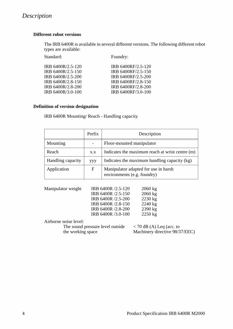
Different robot versions
The IRB 6400R is available in several different versions. The following different robot types are available:
Standard: Foundry:
IRB 6400R/2.5-120 IRB 6400RF/2.5-120IRB 6400R/2.5-150 IRB 6400RF/2.5-150IRB 6400R/2.5-200 IRB 6400RF/2.5-200IRB 6400R/2.8-150 IRB 6400RF/2.8-150IRB 6400R/2.8-200 IRB 6400RF/2.8-200IRB 6400R/3.0-100 IRB 6400RF/3.0-100
Definition of version designation
IRB 6400R Mounting/ Reach - Handling capacity
Manipulator weight IRB 6400R /2.5-120 2060 kg IRB 6400R /2.5-150 2060 kgIRB 6400R /2.5-200 2230 kgIRB 6400R /2.8-150 2240 kg IRB 6400R /2.8-200 2390 kgIRB 6400R /3.0-100 2250 kg
Airborne noise level:The sound pressure level outside < 70 dB (A) Leq (acc. tothe working space Machinery directive 98/37/EEC)
Prefix Description
Mounting - Floor-mounted manipulator
Reach x.x Indicates the maximum reach at wrist centre (m)
Handling capacity yyy Indicates the maximum handling capacity (kg)
Application F Manipulator adapted for use in harsh environments (e.g. foundry)
4 Product Specification IRB 6400R M2000
Description
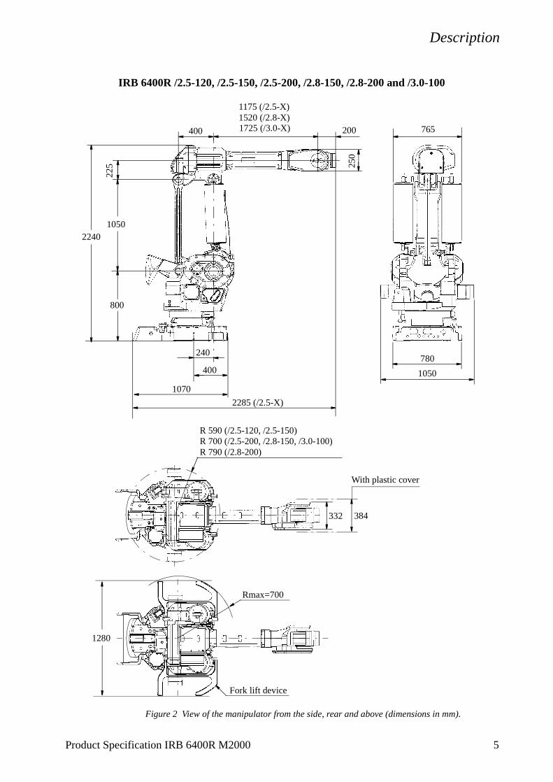
IRB 6400R /2.5-120, /2.5-150, /2.5-200, /2.8-150, /2.8-200 and /3.0-100
Figure 2 View of the manipulator from the side, rear and above (dimensions in mm).
2240
332
R 590 (/2.5-120, /2.5-150)R 700 (/2.5-200, /2.8-150, /3.0-100)R 790 (/2.8-200)
225
2285 (/2.5-X)
800
1050
240
1070
400
1175 (/2.5-X)
200400
1520 (/2.8-X)1725 (/3.0-X)
250
765
780
1050
Rmax=700
1280
Fork lift device
384
With plastic cover
Product Specification IRB 6400R M2000 5
Description
1.2 Safety/Standards
The robot conforms to the following standards:
EN 292-1 Safety of machinery, terminology
EN 292-2 Safety of machinery, technical specifications
EN 954-1 Safety of machinery, safety related parts of control systems
EN 60204 Electrical equipment of industrial machines
IEC 204-1 Electrical equipment of industrial machines
ISO 10218, EN 775 Manipulating industrial robots, safety
ANSI/RIA 15.06/1999 Industrial robots, safety requirements
ISO 9409-1 Manipulating industrial robots, mechanical interface
ISO 9787 Manipulating industrial robots, coordinate systems and motions
IEC 529 Degrees of protection provided by enclosures
EN 50081-2 EMC, Generic emission
EN 50082-2 EMC, Generic immunity
ANSI/UL 1740-1996 (option) Standard for Industrial Robots and Robotic Equipment
CAN/CSA Z 434-94 (option) Industrial Robots and Robot Systems - General Safety Requirements
The robot complies fully with the health and safety standards specified in the EEC’s Machinery Directives.
The robot is designed with absolute safety in mind. It has a dedicated safety system based on a two-channel circuit which is monitored continuously. If any component fails, the electrical power supplied to the motors shuts off and the brakes engage.
Safety category 3Malfunction of a single component, such as a sticking relay, will be detected at the next MOTOR OFF/MOTOR ON operation. MOTOR ON is then prevented and the faulty section is indicated. This complies with category 3 of EN 954-1, Safety of machinery - safety related parts of control systems - Part 1.
Selecting the operating mode The robot can be operated either manually or automatically. In manual mode, the robot can only be operated via the teach pendant, i.e. not by any external equipment.
Reduced speedIn manual mode, the speed is limited to a maximum of 250 mm/s (600 inch/min.).The speed limitation applies not only to the TCP (Tool Centre point), but to all parts of the robot. It is also possible to monitor the speed of equipment mounted on the robot.
Three position enabling deviceThe enabling device on the teach pendant must be used to move the robot when in
6 Product Specification IRB 6400R M2000

Description
manual mode. The enabling device consists of a switch with three positions, meaning that all robot movements stop when either the enabling device is pushed fully in, or when it is released completely. This makes the robot safer to operate.
Safe manual movementThe robot is moved using a joystick instead of the operator having to look at the teach pendant to find the right key.
Over-speed protectionThe speed of the robot is monitored by two independent computers.
Emergency stopThere is one emergency stop push button on the controller and another on the teach pendant. Additional emergency stop buttons can be connected to the robot’s safety chain circuit.
Safeguarded space stopThe robot has a number of electrical inputs which can be used to connect external safety equipment, such as safety gates and light curtains. This allows the robot’s safety functions to be activated both by peripheral equipment and by the robot itself.
Delayed safeguarded space stopA delayed stop gives a smooth stop. The robot stops in the same way as at a normal program stop with no deviation from the programmed path. After approx. 1 second the power supplied to the motors shuts off.
Collision detection (option)In case an unexpected mechanical disturbance like a collision, electrode stik etc appears, the robot will stop and slightly back off from its stop position.
Restricting the working space The movement of each axis can be restricted using software limits. There are safeguarded space stops for connection of limit switches to restrict the working space.Axes 1-3 can also be restricted by means of mechanical stops.
Hold-to-run control“Hold-to-run” means that you must depress the start button in order to move the robot. When the button is released the robot will stop. The hold-to-run function makes program testing safer.
Fire safetyBoth the manipulator and control system comply with UL’s (Underwriters Laboratory) tough requirements for fire safety.
Safety lamp (option)As an option, the robot can be equipped with a safety lamp mounted on the manipula-tor. This is activated when the motors are in the MOTORS ON state.
Product Specification IRB 6400R M2000 7

Description
1.3 Installation
All the versions of IRB 6400R are designed for floor mounting. Depending on the robot version an end effector of max. weight 100 to 200 kg, including payload, can be mounted on the mounting flange (axis 6). See Load diagrams on page 10.
Extra loads (valve packages, transformers) can be mounted on the upper arm. On all versions an extra load can also be mounted on the frame of axis 1. Holes for mounting extra equipment on page 17.
The working range of axes 1-3 can be limited by mechanical stops. Position switches can be supplied on axes 1-3 for position indication of the manipulator.
Operating requirements
Protection standards
Standard Manipulator IP54Wrist IP55
Foundry Manipulator IP67Upper arm IP67Wrist IP67
Explosive environmentsThe robot must not be located or operated in an explosive environment.
Ambient temperatureManipulator during operation +5oC (41oF) to +50oC (122oF)Complete robot during transportation and storage, -25oC (13oF) to +55oC (131oF)for short periods (not exceeding 24 hours) up to +70oC (158oF)
Relative humidityComplete robot during transportation and storage Max. 95% at constant temperatureComplete robot during operation Max. 95% at constant temperature
Mounting the manipulator
Maximum load in relation to the base coordinate system.
Endurance load Max. load at in operation emergency stop
Force xy ±14000 N ±38000 NForce z 22000 ±8000 N 22000 ±19000 N
Torque xy ±34000 Nm ±61000 NmTorque z ±7000 Nm ±15000 Nm
8 Product Specification IRB 6400R M2000

Description
Figure 3 Hole configuration (dimensions in mm).
0.4
R 400
∅
317.34
A - A
A A
B B
B - B
(4x)
243.5 (4x)
317.
34(4
x)
243.
5(4
x)
(37.5°) (4x)
53 (8x)∅
28 (8x)∅
45 H9 (4x)∅
15+2
100
Y
XZ
(15°) (4x)
0
+0.50
Product Specification IRB 6400R M2000 9
Description
10 Product Specification IRB 6400R M2000
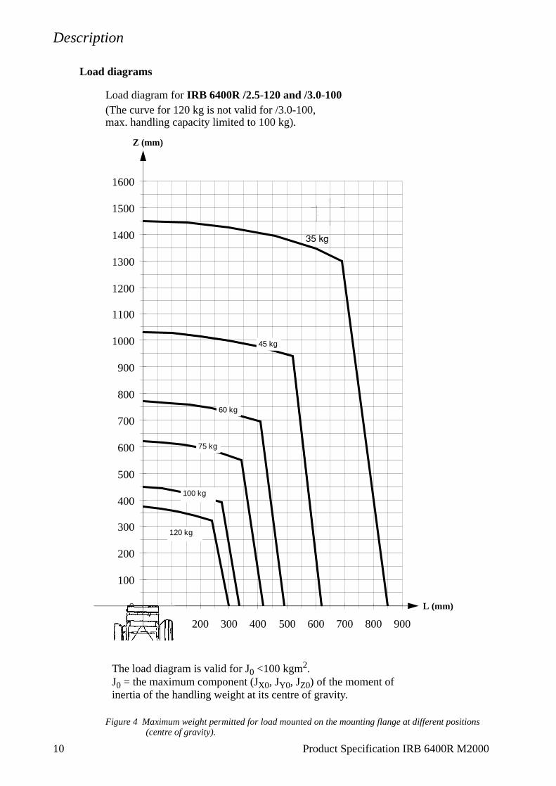
Load diagrams
Load diagram for IRB 6400R /2.5-120 and /3.0-100(The curve for 120 kg is not valid for /3.0-100, max. handling capacity limited to 100 kg).
Figure 4 Maximum weight permitted for load mounted on the mounting flange at different positions (centre of gravity).
The load diagram is valid for J0 <100 kgm2.J0 = the maximum component (JX0, JY0, JZ0) of the moment of inertia of the handling weight at its centre of gravity.
0
100
200
300
400
500
600
700
800
900
1000
1100
1200
1300
1400
1500
1600
0 100 200 300 400 500 600 700 800 900
120 kg
45 kg
30 kg
75 kg
60 kg
100 kg
L (mm)
Z (mm)
�����

Description
Load diagram for IRB 6400R /2.5-150 and /2.8-150
Figure 5 Maximum weight permitted for load mounted on the mounting flange at different positions (centre of gravity).
The load diagram is valid for J0 <100 kgm2.J0 = the maximum component (JX0, JY0, JZ0) of the moment of inertia of the handling weight at its centre of gravity.
0
100
200
300
400
500
600
700
800
900
0 100 200 300 400 500
L (mm)
Z (mm)150
125 kg
100 kg
75 kg
Z (mm)
L (mm)
Product Specification IRB 6400R M2000 11

Description
Load diagram for IRB 6400R /2.5-200 and /2.8-200
Figure 6 Maximum weight permitted for load mounted on the mounting flange at different positions (centre of gravity).
The load diagram is valid for J0 <100 kgm2.J0 = the maximum component (JX0, JY0, JZ0) of the moment of inertia of the handling weight at its centre of gravity.
Load diagram for IRB 6400R /2.5-200 and /2.8-200 M2000
0
100
200
300
400
500
600
700
800
0 100 200 300 400 500
L (mm)
Z (mm)200 kg
175 kg
150 kg
125 kg
100 kg
Z (mm)
L (mm)
12 Product Specification IRB 6400R M2000

Description
Handling capacity for IRB 6400R /2.8-150 in press-tending application
Note! Option 090, Cooling for axis 1 motor, must be installed.
The weight and dimensions of the part and gripper are limited by the maximum static torque and moment of inertia.
Figure 7 A-movement (inward movement).
Figure 8 B-movement.
Static torque: A-movement Axis 5 Ma5 < 900 NmB-movement Axis 4 Mb4 < 900 Nm
Moment of inertia: A-movement Axis 5, Ja5 < 105 kgm2 Axis 6, Ja6 < 120 kgm2
B-movement Axis 4, Jb4 < 105 kgm2 Axis 5, Jb5 < 120 kgm2
Approximations of M and J can be calculated using the following formula:Ma5 = 9.81 • (mg • r + mp • s) (Nm)Mb4 = 9.81 • (mg • (r + 0.2) + mp • (s + 0.2)) (Nm)Ja5 = mg / 12 • c2 + mg • r2 + mp / 12 • a2 + mp • s2 (kgm2)
Ja6 = mg / 12 • c2 + mg • r2 + mp / 12 • (a2 + b2) + mp • s2 (kgm2)
Jb4 = mg / 12 • c2 + mg • (r + 0.2)2 + mp / 12 • a2 + mp • (s + 0.2)2 (kgm2)
Jb5 = mg / 12 • c2 + mg • (r + 0.2)2 + mp / 12 • (a2 + b2) + mp • (s + 0.2)2 (kgm2)
mg = weight of gripper (kg) mp = weight of part (kg)Distances a, b, c, r and s (m) are shown in Figure 9.
Press Press
Movement mainly with axes 1 and 6
Wrist
Part
Part
Press Press
Movement mainly with axes 1, 2, 3 and 4
Wrist
Part
Part
Product Specification IRB 6400R M2000 13

Description
Figure 9 Distances r and s (m).
Grippermg
r
s
mp
A-movement, gripper perpendicular to axis 6
Part
B-movement, gripper parallel to axis 6
Gripper r
s
mp
mg
Dimensions of gripper and part
TCP 0
c
a
Gripper
b
Part
Part
14 Product Specification IRB 6400R M2000
Description
Product Specification IRB 6400R M2000 15
Mounting equipment
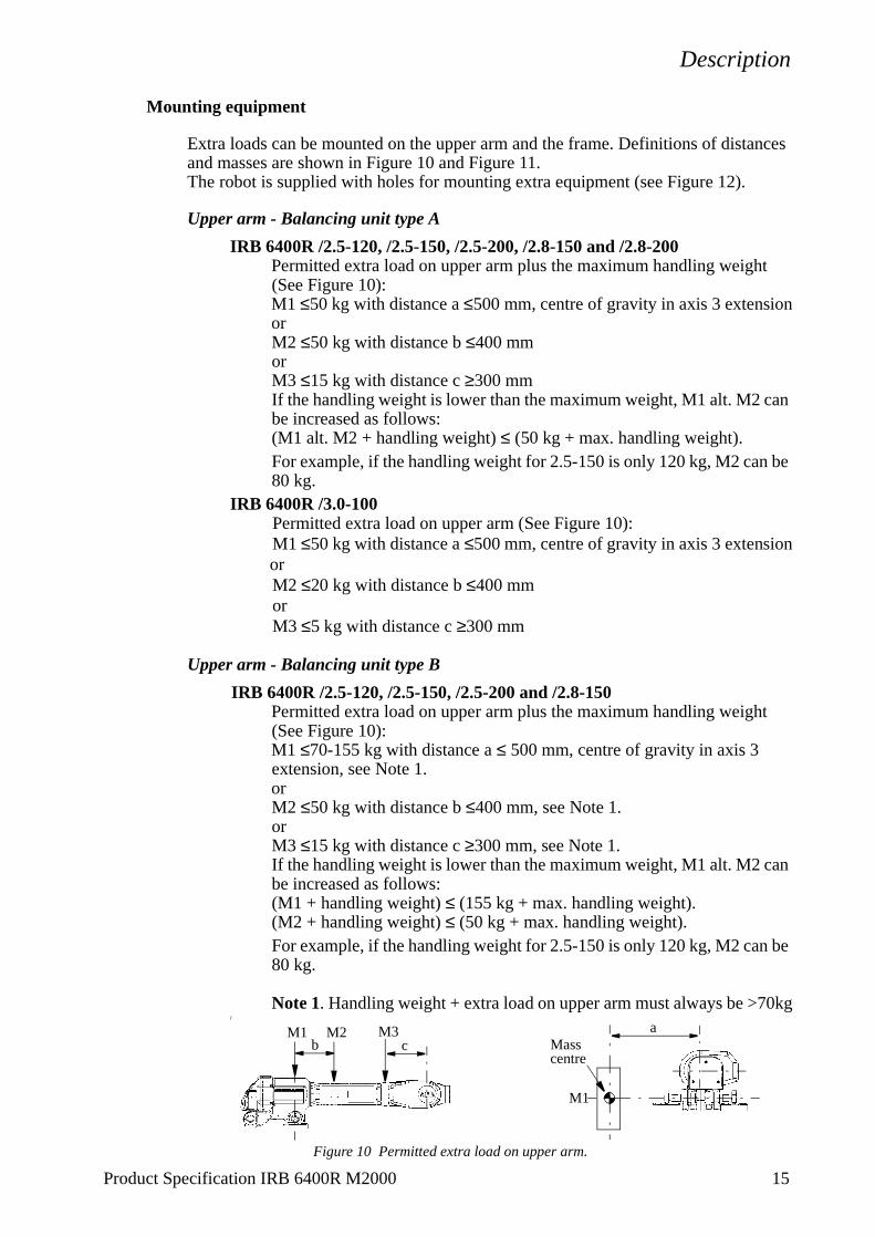
Extra loads can be mounted on the upper arm and the frame. Definitions of distances and masses are shown in Figure 10 and Figure 11.The robot is supplied with holes for mounting extra equipment (see Figure 12).
Upper arm - Balancing unit type A
IRB 6400R /2.5-120, /2.5-150, /2.5-200, /2.8-150 and /2.8-200Permitted extra load on upper arm plus the maximum handling weight (See Figure 10):M1 ≤50 kg with distance a ≤500 mm, centre of gravity in axis 3 extensionorM2 ≤50 kg with distance b ≤400 mmorM3 ≤15 kg with distance c ≥300 mmIf the handling weight is lower than the maximum weight, M1 alt. M2 can be increased as follows:(M1 alt. M2 + handling weight) ≤ (50 kg + max. handling weight).For example, if the handling weight for 2.5-150 is only 120 kg, M2 can be 80 kg.
IRB 6400R /3.0-100Permitted extra load on upper arm (See Figure 10):M1 ≤50 kg with distance a ≤500 mm, centre of gravity in axis 3 extensionorM2 ≤20 kg with distance b ≤400 mmorM3 ≤5 kg with distance c ≥300 mm
Upper arm - Balancing unit type B
IRB 6400R /2.5-120, /2.5-150, /2.5-200 and /2.8-150Permitted extra load on upper arm plus the maximum handling weight (See Figure 10):M1 ≤70-155 kg with distance a ≤ 500 mm, centre of gravity in axis 3 extension, see Note 1.orM2 ≤50 kg with distance b ≤400 mm, see Note 1.orM3 ≤15 kg with distance c ≥300 mm, see Note 1.If the handling weight is lower than the maximum weight, M1 alt. M2 can be increased as follows:(M1 + handling weight) ≤ (155 kg + max. handling weight).(M2 + handling weight) ≤ (50 kg + max. handling weight).For example, if the handling weight for 2.5-150 is only 120 kg, M2 can be 80 kg.
Note 1. Handling weight + extra load on upper arm must always be >70kg/
Figure 10 Permitted extra load on upper arm.
Masscentre
ab c
M1
M2 M3M1

Description
Frame (Hip Load)
Permitted extra load on frame is JH = 120 kgm2.Recommended position (see Figure 11).JH = JH0 + M4 • R2
where JH0 is the moment of inertia of the equipmentR is the radius (m) from the centre of axis 1 M4 is the total mass (kg) of the equipment including
bracket and harness (≤320 kg)
Figure 11 Extra load on frame of IRB 6400R (dimensions in mm).
Mounting of hip load
The extra load can be mounted either on the fork lift device or on the frame. Holes for mounting see Figure 13.
When mounting on the frame all the six holes (2x3, ∅ 18 ) on one side must be used.
400
RR
M4JH0
View from above View from the rear
914754
16 Product Specification IRB 6400R M2000

Description
Holes for mounting extra equipment
Figure 12 Holes for mounting extra equipment on the upper arm (dimensions in mm).
AA
B - B
D - D E - E
282
93
260
75150
150180
M10 (2x) See E-E
104 for “Hole 1”
C - C
F
F
93 for “Hole 2”See E-E
“Hole 1” “Hole 2”
112
A - A
B B
C C
175
690 (/2.5-X)
50
M10 (4x)
1035 (/2.8-X)1240 (/3.0-X)
M10 (2x)
25
M10 (4x) Depth 20
E
ED
D
(View F-F, seeFigure 14)
M10 (2x)
80
378M10 (2x)
Product Specification IRB 6400R M2000 17

Description
Figure 13 Holes for mounting of extra load on the fork lift device and the frame (dimensions in mm).
Figure 14 The mechanical interface (mounting flange) ISO 9409-1-A125 (dimensions in mm).
As an option there is an electrically insulated tool flange.For more information see page 40 and Figure 28.
50
84 100
18 (2x3)∅
212
572
134254
361
120 65
M10 Depth min 20
(8x) on both sides
View from above
on both sides
D=
160
h7
D=
80 H
7
8
8
30o
60o
D=10 H7 depth 10
M10 (6x) depth 18
D=125
F - F
18 Product Specification IRB 6400R M2000
Description
1.4 Maintenance and Troubleshooting
The robot requires only a minimum of maintenance during operation. It has been designed to make it as easy to service as possible:
- Maintenance-free AC motors are used.
- Liquid grease or oil is used for the gear boxes.
- The cabling is routed for longevity, and in the unlikely event of a failure, its modular design makes it easy to change.
The following maintenance is required:
- Changing filter for the transformer/drive unit cooling every year.
- Changing batteries every third year.
The maintenance intervals depends on the use of the robot. For detailed information on maintenance procedures, see Maintenance section in the Product Manual.
Product Specification IRB 6400R M2000 19

Description
20 Product Specification IRB 6400R M2000
1.5 Robot Motion
Type of motion Range of movement
Axis 1 Rotation motion +180o to -180o Axis 2 Arm motion +85o to -70o Axis 3 Arm motion +110o to -28o
Axis 4 Wrist motion +300o to -300o Axis 5 Bend motion +120o to -120o Axis 6 Turn motion +300o to -300o
Figure 15 The extreme positions of the robot arm
909
1083
1229
2469
2800
2999
305
645
848
2600
2762
2859
1
2
3
4
5
6
0
2.5-X
2.8-X
3.0-X
pos. axis 2 (ϕ2)
axis 3 (ϕ3)
0123456
0-70-7043858537
0-28
-311011020
-28
Min. 23o Max. 155o 90o at pos. 0
1415185415766
109624671804
207519091445387
-290701
2389
1760490760648978
27912108
207520711463
63-614583
2551
1965671964578908
29842289
0123456
Positions at wrist centre (mm)
Pos.
2.5 3.0-1002.8-150 -200
xz z zx x
Angle ϕ2, ϕ3 (degrees)
Angle 2/3 (ϕ2/ϕ3)
All dimensions refer to the wrist centre (mm)
-120 -150 -200
207521681474-130-806513
2647
ϕ2
ϕ2/ϕ3ϕ3
X
Z
+
+

Description
Performance according to ISO 9283
At rated load and 1 m/s velocity on the inclined ISO test plane with all six robot axes in motion.
Unidirectional pose repeatability: RP = 0.1 mm
Linear path accuracy: AT = 1.6 - 2.1 mm
Linear path repeatability:RT = 0.4 - 0.6 mm (IRB 6400R/2.5-120, 2.5-150, 2.8-150)RT = 0.8 - 1.0 mm (Others)
Minimum positioning time, to within 0.4 mm of the position:0.2 - 0.25 sec. (IRB 6400R/2.5-120, 2.5-150 on 35 mm linear path)0.5 - 0.6 sec. (IRB 6400R/2.5-120, 2.5-150 on 350 mm linear path)0.25 - 0.35 sec. (Others, on 35 mm linear path)0.6 - 0.7 sec. (Others, on 350 mm linear path)
The above values are the range of average test-results from a number of robots. If guaranteed values are required, please contact your nearest ABB office.
Velocity
IRB 6400R versions: 2.5-120 2.5-150 2.8-2003.0-100 2.5-200
2.8-150Axis no.
1 110°/s 100°/s 90°/s2 100°/s 90°/s 70°/s3 100°/s 90°/s 70°/s4 210°/s 120°/s 110°/s5 150°/s 120°/s 110°/s6 210°/s 190°/s 110°/s
There is a supervision function to prevent overheating in applications with intensive and frequent movements.
Resolution
Approx. 0.01o on each axis.
Product Specification IRB 6400R M2000 21
Description
1.6 Application Interface
The robot can be supplied with integrated power, signals, customer buses, servo signals and air hose to the upper arm housing (options 041, 043 and 177/178) or power, signals, customer buses and air hose to the upper arm axis 4 (option 042).
Specification
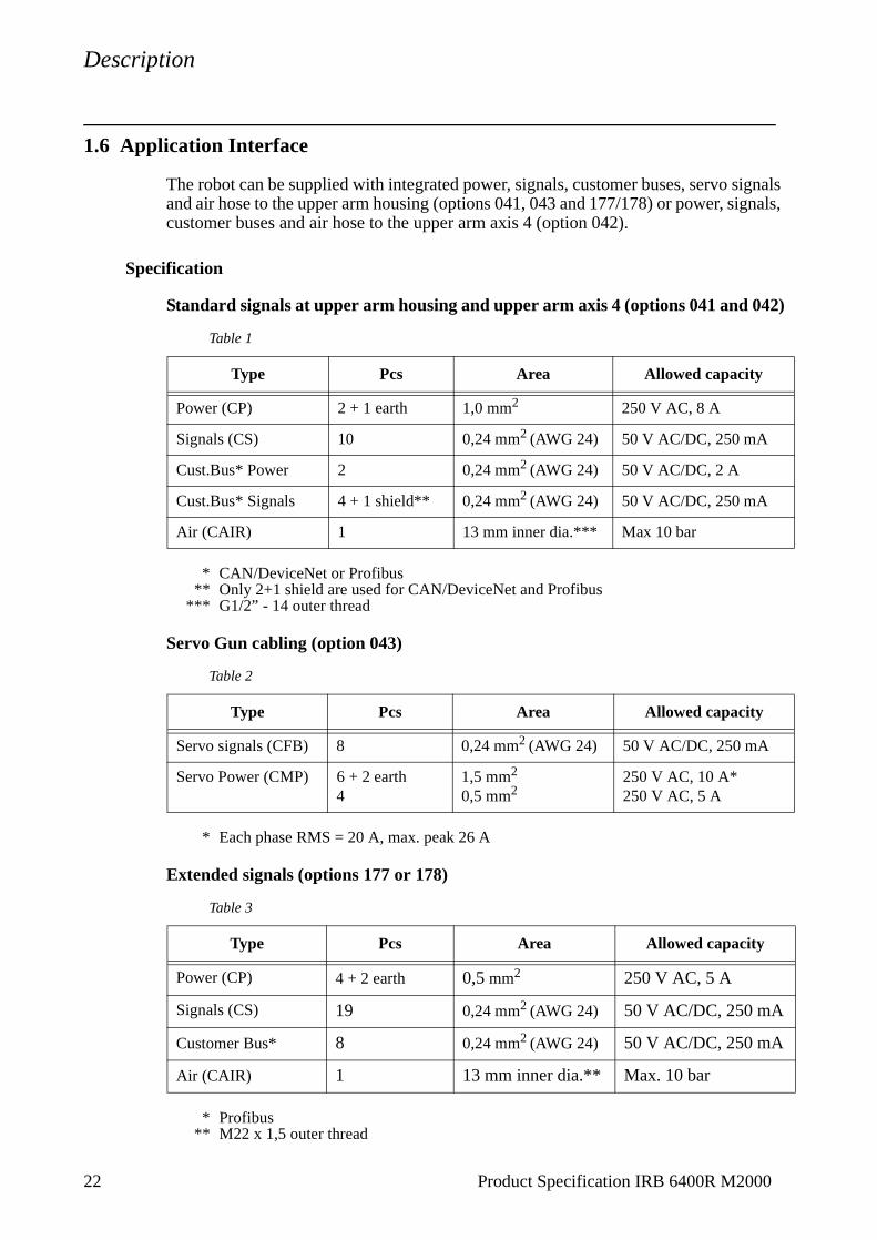
Standard signals at upper arm housing and upper arm axis 4 (options 041 and 042)
* CAN/DeviceNet or Profibus** Only 2+1 shield are used for CAN/DeviceNet and Profibus
*** G1/2” - 14 outer thread
Servo Gun cabling (option 043)
* Each phase RMS = 20 A, max. peak 26 A
Extended signals (options 177 or 178)
* Profibus** M22 x 1,5 outer thread
Table 1
Type Pcs Area Allowed capacity
Power (CP) 2 + 1 earth 1,0 mm2 250 V AC, 8 A
Signals (CS) 10 0,24 mm2 (AWG 24) 50 V AC/DC, 250 mA
Cust.Bus* Power 2 0,24 mm2 (AWG 24) 50 V AC/DC, 2 A
Cust.Bus* Signals 4 + 1 shield** 0,24 mm2 (AWG 24) 50 V AC/DC, 250 mA
Air (CAIR) 1 13 mm inner dia.*** Max 10 bar
Table 2
Type Pcs Area Allowed capacity
Servo signals (CFB) 8 0,24 mm2 (AWG 24) 50 V AC/DC, 250 mA
Servo Power (CMP) 6 + 2 earth4
1,5 mm2
0,5 mm2250 V AC, 10 A*250 V AC, 5 A
Table 3
Type Pcs Area Allowed capacity
Power (CP) 4 + 2 earth 0,5 mm2 250 V AC, 5 A
Signals (CS) 19 0,24 mm2 (AWG 24) 50 V AC/DC, 250 mA
Customer Bus* 8 0,24 mm2 (AWG 24) 50 V AC/DC, 250 mA
Air (CAIR) 1 13 mm inner dia.** Max. 10 bar
22 Product Specification IRB 6400R M2000

Description
1.7 Spotweld Base Harness and Spotweld Base Harness Extended
The robot can be supplied with an integrated spotweld base harness (option 047), or an integrated spotweld base harness extended (option 044).
The integrated spotweld base harness (hose fittings: G1/2”-14 outer thread) or the integrated spotweld base harness extended (hose fittings: M22 x 1,5 outer thread) is used to supply primary current and cooling water to the upper arm. Connections at the manipulator base and at the upper arm housing. For more information, see Figure 23 and Figure 24.
Specification
Spotweld base harness (option 047)
* at +20oC ambient temperature and 100 A at +50oC ambient temperature.Max. current 2,5 kA/1s, (short-circuit current) 1,5 kA/3s.Max. voltage 600 V, frequency 50-1000 Hz.
** G1/2” - 14 outer thread.
Spotweld base harness extended (option 044)
* at +20oC ambient temperature and 100 A at +50oC ambient temperature.Max. current 2,5 kA/1s, (short-circuit current) 1,5 kA/3s.Max. voltage 600 V, frequency 50-1000 Hz.
** M22 x 1,5 outer thread.
Table 4
Type Pcs Area Allowed capacity
Power (WELD) 2 + 1 earth 25 mm2 Max. aver. curr. 135 A*
Process (PROC 1-3) 3 13 mm inner dia.** Max. 10 bar
Table 5
Type Pcs Area Allowed capacity
Power (WELD) 2 + 1 earth 25 mm2 Max. aver. curr. 135 A*
Process (PROC 1-3) 3 13 mm inner dia.** Max. 10 bar
Product Specification IRB 6400R M2000 23

Description
1.8 Upper Arm Harness
The upper arm harness is available for material handling (MH) application (for 2,5, 2,8 and 3,0 m manipulator) and spotwelding (SW) application (for 2,5 and 2,8 m manipulator).
The upper arm harness for material handling is available in two different variants:
• MH Standard (option 066)
• MH Extended (option 067)
The upper arm harness for spotwelding is available in four different variants:
• SW Pneumatic Standard (option 106)
• SW Pneumatic Extended (option 107)
• SW Servo Standard (option 108)
• SW Servo Extended (option 109)
Specification
MH Standard (option 066)
* Max. allowed current due to less area in cables between base to axis 3.** G1/2” - 14 outer thread.
MH Extended (option 067)
* Max. allowed current due to less area in cables between base to axis 3.** M22 x 1,5 mm outer thread.
Table 6
Type Pcs Area Allowed capacity
Power (CP) 2 + 1 earth 1,0 mm2 250 V AC, 8 A
Signals (CS) 10 1,0 mm2 50 V AC/DC, 250 mA*
Air (CAIR) 1 12,5 mm inner dia.** Max 10 bar
Table 7
Type Pcs Area Allowed capacity
Power (CP) 6 1,0 mm2 250 V AC, 5 A*
Signals (CS) 18 + 1 shield 1,0 mm2 50 V AC/DC, 250 mA*
Air (CAIR) 1 12,5 mm inner dia.** Max 10 bar
24 Product Specification IRB 6400R M2000

Description
SW Pneumatic Standard (option 106)
* Max. allowed current due to less area in cables between base to axis 3.** G1/2” - 14 outer thread.
*** At +20oC ambient temperature and 100 A at +50oC ambient temperature.Max. current 2,5 kA/1s, (short-circuit current) 1,5 kA/3s.Max. voltage 600 V, frequency 50-1000 Hz.
SW Servo Standard (option 108)
Additional to “SW Pneumatic Standard” (option 106)
* Max. allowed current due to less area in cables between base to axis 3.** Each phase RMS = 20 A
SW Pneumatic Extended (option 107)
* Max. allowed current due to less area in cables between base to axis 3.** M22 x 1,5 outer thread.
*** At +20oC ambient temperature and 100 A at +50oC ambient temperature.Max. current 2,5 kA/1s, (short-circuit current) 1,5 kA/3s.Max. voltage 600 V, frequency 50-1000 Hz.
Table 8
Type Pcs Area Allowed capacity
Weld (WELD) 2 + 1 earth 25 mm2 Max. aver. curr. 135 A***
Power (CP) 2 + 1 earth 1,0 mm2 250 V AC, 8 A
Signals (CS) 10 1,0 mm2 50 V AC/DC, 250 mA*
Air (CAIR) 1 12,5 mm inner dia.** Max 10 bar
Process (PROC 1-3) 3 12,5 mm inner dia.** Max 10 bar
Table 9
Type Pcs Area Allowed capacity
Servo signals (CFB) 6 0,5 mm2 50 V AC/DC, 250 mA*
Servo power (CMP) 10 +2 earth 1,0 mm2 6+2 earth 250 V AC, 7 A**4 250 V AC, 5 A
Table 10
Type Pcs Area Allowed capacity
Weld (WELD) 2 + 1 earth 25 mm2 Max. aver. curr. 135 A***
Power (CP) 4 + 2earth 1,0 mm2 250 V AC, 5 A
Signals (CS) 19 1,0 mm2 50 V AC/DC, 250 mA*
Air (CAIR) 1 12,5 mm inner dia.** Max 10 bar
Process (PROC 1-3) 3 12,5 mm inner dia.** Max 10 bar
Product Specification IRB 6400R M2000 25

Description
SW Servo Extended (option 109)
Additional to “SW Pneumatic Extended” (option 107)
* Max. allowed current due to less area in cables between base to axis 3.** Each phase RMS = 14 , max. peak 26 AA
1.9 Dresspack examples
The tables below (12-13) are examples showing which options are included in typical Dresspack solutions.
Table 11
Type Pcs Area Allowed capacity
Servo signals (CFB) 6 0,5 mm2 50 V AC/DC, 250 mA*
Servo power (CMP) 10 +2 earth 1,0 mm2 6+2 earth 250 V AC, 7 A**4 250 V AC, 5 A
Table 12
DresspackOption for
MH Standard SW PneumaticStandard
SW ServoStandard
Total IRB Opt. 056 or 057 Opt. 056 or 057 056 or 057 + 681-684
Axes 1-3 Opt. 041 Opts. 041 + 047 Opts. 041+047+043
Axes 3-6 Opt. 066 Opt. 106 Opt. 108
Table 13
DresspackOption for
MH Extended SW PneumaticExtended
SW ServoExtended
Total IRB Opt. 177 or 178 Opt. 177 or 178 177 or 178 + 681-684
Axes 1-3 Opt. 177 or 178 Opt. 177/178 + 044 177 or 178 + 044 + 043
Axes 3-6 Opt. 067 Opt. 107 Opt. 109
26 Product Specification IRB 6400R M2000
Description
1.10 Servo Gun
The robot can be supplied with hardware and software for Stationary Gun, Robot Gun, Stationary and Robot Gun, Twin Stationary Guns, Stationary Gun and Track Motion or Robot Gun and Track Motion For configuration and specification of hardware and software respectively, see each chapter below.
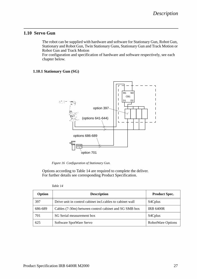
1.10.1 Stationary Gun (SG)
Figure 16 Configuration of Stationary Gun.
Options according to Table 14 are required to complete the deliver.For further details see corresponding Product Specification.
Table 14
Option Description Product Spec.
397 Drive unit in control cabinet incl.cables to cabinet wall S4Cplus
686-689 Cables (7-30m) between control cabinet and SG SMB box IRB 6400R
701 SG Serial measurement box S4Cplus
625 Software SpotWare Servo RobotWare Options
M1 M2
D1 D2
CB1
SMB
M7C1B1.CFG
options 686-689
(options 641-644)
option 397
option 701
Product Specification IRB 6400R M2000 27
Description
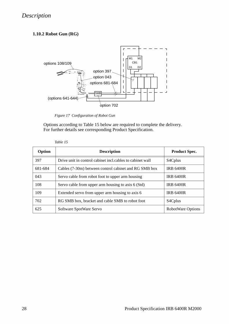
1.10.2 Robot Gun (RG)
Figure 17 Configuration of Robot Gun
Options according to Table 15 below are required to complete the delivery.For further details see corresponding Product Specification.
Table 15
Option Description Product Spec.
397 Drive unit in control cabinet incl.cables to cabinet wall S4Cplus
681-684 Cables (7-30m) between control cabinet and RG SMB box IRB 6400R
043 Servo cable from robot foot to upper arm housing IRB 6400R
108 Servo cable from upper arm housing to axis 6 (Std) IRB 6400R
109 Extended servo from upper arm housing to axis 6 IRB 6400R
702 RG SMB box, bracket and cable SMB to robot foot S4Cplus
625 Software SpotWare Servo RobotWare Options
M1 M2
D1 D2
CB1
SMB
option 043
(options 641-644)
option 397
options 681-684
options 108/109
option 702
28 Product Specification IRB 6400R M2000

Description
1.10.3 Stationary and Robot Gun (SG + RG)
Figure 18 Configuration of Stationary and Robot Gun.
Options according to Table 16 below are required to complete the delivery.For further details see corresponding Product Specification.
Table 16
Option Description Product Spec.
397 Drive unit in control cabinet incl.cables to cabinet wall S4Cplus
681-684 Cables (7-30m) between control cabinet and RG SMB box IRB 6400R
043 Servo cable from robot foot to upper arm housing IRB 6400R
108 Servo cable from upper arm housing to axis 6 (standard) IRB 6400R
109 Extended servo from upper arm housing to axis 6 IRB 6400R
703 RG SMB box, bracket, cable to robot foot and SG SMB box S4Cplus
380 DDU in separate box and cable (1m) to SG SMB box S4Cplus
686-689 Cables (7-30m) between control cabinet an SG SMB box IRB 6400R
626 Software SpotWare Servo RobotWare Options
M1 M2
D1 D2
CB1
M1 M2
D1 D2
CB2
M7C1B1.CFG
SMB
DD
U
SMB
option 380
option 043option 397
options 686-689
options 108/109
options 681-684
(options 641-644)
option 703
Product Specification IRB 6400R M2000 29

Description
1.10.4 Twin Stationary Guns (SG + SG)
Figure 19 Configuration of Twin Stationary Guns.
Options according to Table 17 below are required to complete the delivery.For further details see corresponding Product Specification.
Table 17
Option Description Product Spec.
397 Drive unit in control cabinet incl.cables to cabinet wall S4Cplus
686-689 Cables (7-30m) between control cabinet and SG1 SMB box, SG2 SMB box and SG2 DDU
IRB 6400R
704 SG1 SMB box and SG2 SMB box S4Cplus
380 DDU in separate box and cable (1m) to SG2 SMB box S4Cplus
625 Software SpotWare Servo RobotWare Options
M1 M2
D1 D2
CB1
M1 M2
D1 D2
CB2
M7C1B1.CFG
DD
U
SMB
option 380
option 397
options 686-689
SMB
(options 641-644)
option 704
SG 1
SG 2
30 Product Specification IRB 6400R M2000

Description
1.10.5 Stationary Gun and Track Motion
Figure 20 Configuration of Stationary Gun and Track Motion.
Options according to below are required to complete the delivery.For further details see corresponding Product Specification.
Note! Track Motion SMB box and cables to the control cabinet are included in the IRBT 6002/6003 delivery.
Table 18
Option Description Product Spec.
397 Drive unit in control cabinet incl.cables to cabinet wall S4Cplus
686-689 Cables (7-30m) between control cabinet, SG SMB box and Track Motion DDU
IRB 6400R
705 SG SMB box S4Cplus
380 Track Motion DDU in separate box S4Cplus
625 Software SpotWare Servo RobotWare Options
M1 M2
D1 D2
CB1
M1 M2
D1 D2
CB2
M7C1B1.CFG
SMB
option 397
SMB DDU
options 686-689
option 380
(options 641-644)
option 705
Product Specification IRB 6400R M2000 31

Description
1.10.6 Robot Gun and Track Motion (RG + TM)
Figure 21 Configuration of Robot Gun and Track Motion.
Options according to Table 19 below are required to complete the delivery.For further details see corresponding Product Spcefication.
Note! Track Motion SMB box, cables to the control cabinet and cable between SMB and DDU are included in the IRBT 6002/6003 delivery.
Table 19
Option Description Product Spec.
397 Drive unit in control cabinet incl.cables to cabinet wall S4Cplus
681-684 and 706
Cables (7-30m) between control cabinet and Track Motion DDU
IRB 6400R
043 Servo cable from robot foot to upper arm housing IRB 6400R
108 Servo cable from upper arm housing to axis 6 (standard) IRB 6400R
109 Extended servo cable from upper arm housing to axis 6 IRB 6400R
380 Track motion DDU in separate box S4Cplus
625 Software SpotWare Servo RobotWare Options
M1 M2
D1 D2
CB1
M1 M2
D1 D2
CB2
M7C1B1.CFG
option 397
SMB DDU options 681-684
options 108/109
option 043
(options 641-644)
32 Product Specification IRB 6400R M2000

Specification of Variants and Options
2 Specification of Variants and Options
The different variants and options for the IRB 6400R are described below.The same numbers are used here as in the Specification form. For controller options, see Product Specification S4Cplus, and for software options, see Product Specification RobotWare Options.
1 MANIPULATOR
VARIANTS
Standard Foundry (requires option 035) (requires option 036)
022 IRB 6400R/2.5-120 IRB 6400RF/2.5-120023 IRB 6400R/2.5-150 IRB 6400RF/2.5-150024 IRB 6400R/2.5-200 IRB 6400RF/2.5-200025 IRB 6400R/2.8-150 IRB 6400RF/2.8-150026 IRB 6400R/2.8-200 IRB 6400RF/2.8-200027 IRB 6400R/3.0-100 IRB 6400RF/3.0-100
IRB 6400R/Reach-Handling capacity
Reach: Specifies the max. reach at the wrist centre.Handling capacity: Specifies the max. handling capacity.
Manipulator colour
330 ABB standardThe manipulator is painted with ABB orange.
352 RAL codeThe manipulator is painted with chosen RAL-colour.
Protection
035 Standard
036 FoundryRobot adapted for foundry or other harsh environments.The robot has the FoundryPlus protection which means that the whole manipulator is IP67 classified and steam washable. An excellent corrosion protection is obtained by a special coating. The connectors are designed for severe environment, and bearings, gears and other sensitive parts are high protected Only available colour is ABB orange Foundry.
039 Extra load upper armThis option should be chosen if the weight of extra equipment on the upper arm exceeds 50 kg. (The manipulator is then equipped with different balancing cylinders for axis 2).For more information, see Mounting equipment on page 15.Not available for options 026, 027.
Product Specification IRB 6400R M2000 33
Specification of Variants and Options
34 Product Specification IRB 6400R M2000
APPLICATION INTERFACE
Air supply and signals for extra equipment to upper arm
A hose for compressed air is integrated into the manipulator. There is an inlet at the base, see Figure 23, and an outlet on the upper arm housing or on the upper arm axis 4, see Figure 22.Connection: G 1/2”-14 in the upper arm housing/upper arm and G 1/2”-14 at the base.
For connection of extra equipment on the manipulator, there are cables running parallel to the manipulator’s cable harness with connectors on the upper arm axis 4 or on the upper arm housing. The connectors are:
- one FCI 12-pin UT071412 SH44N (CS)
- one FCI 4-pin UT07104 SH44N (CP)
- one fieldbus (opt. 053/054)
Customer connection sets for R2.CS, R2.CP, R3.CANBUS or R3.PBUS are available as options. More information in Product Manual IRB 6400R/Installation.
For connection of servo gun on the manipulator there are cables running in parallel to the manipulator’s cable harness with connectors on the upper arm housing (only).The connectors are:
- one FCI 12-pin UT071412 SH44N (CMP)
- one FCI 12-pin UT071412 SH44N (CFB)
Air supply and extended signals for extra equipment to upper arm
A hose for compressed air is integrated into the manipulator. There is an inlet at the base, see Figure 23, and an outlet on the upper arm housing (only), see Figure 22.Connection: M 22 x 1,5 mm, cone angle 24o (ISO 8434-1) both at the base and at the upper arm housing.
For connection of extra equipment which requires extended signals on the manipulator, there are cables running in parallel to the manipulator’s cable harness with connectors on the upper arm housing (only). The connectors are:
- one FCI 19-pin MSK07C1419S (CS)
- one FCI 6-pin MSK07C106S (CP)
- one FCI 10-pin MSK07C1210S (opt. 053/054)
For connection of servo gun which requires extended signals on the manipulator there are cables running in parallel to the manipulator’s cable harness with connectors on the upper arm housing (only). The connectors are:
- one FCI 12-pin UT071412SH44N (CMP)
- one FCI 12-pin UT071412SH44N (CFB)

Specification of Variants and Options
Media outlet
041 At upper arm housingFor specification of connections, see Chapter 1.6, Table 1.
042 At upper arm axis 4For specification of connections, see Chapter 1.6, Table 1.
043 Servo Gun cablingFor specification of connections, see Chapter 1.6, Table 2.
Extended signals with connection to
177 Manipulator (Cables from robot base to axis 3)The extended signals are connected directly to the manipulator base to one heavy duty industrial housing with three D-sub connector inserts, R1.CP/CS (see Figure 23).The cables from the cabinet to the manipulator base are not supplied.For specification of connections, see Chapter 1.6, Table 3.
178 Cabinet (Cables from controller to axis 3)The extended signals CP/CS comes from the cabinet, through cable glands, and are connected to the manipulator base.The cables between the controller and R1.CP/CS are supplied.For specification of connections, see Chapter 1.6, Table 3.
Figure 22 Location of customer connections on upper arm / armhouse.
R2.CAIR
R3.CANBUS/
R3.CANBUS/*
R2.CAIRR2.CS
R2.CS*
R2.CP
R2.CP
Option 041 and 177/178
Option 042
R3.IBUS/PBUS
R3.IBUS/PBUS
R2.CMP
R2.CFB
Option 043
* Changed location with each otherfor extended signals (177/178)
Product Specification IRB 6400R M2000 35

Specification of Variants and Options
Figure 23 Location of customer connections on base.
Connection to
056 ManipulatorThe signals are connected directly to the manipulator base to one heavy duty industrial housing with three D-sub connector inserts, R1.CP/CS (see Figure 23). The cables from the manipulator base are not supplied.(The foundry version, option 036, has a housing for extra harsh environment)
057 CabinetThe signals CP/CS are connected to 12-pole screw terminals, Phoenix MSTB 2.5/12-ST-5.08, in the controller. The cable between R1.CP/CS and the controller is supplied.
Connectors type
Type of fieldbus connectors on the upper arm
053 Can/DeviceNet, R3.CANBUS5-pin “Mini” style female connector with 7/8-16 UN-2A THD female connection thread. Meets ANSI/B93.55M-1981 design and intermateability requirements.
054 Profibus, R3.PBUS9-pin connector with M23 connection thread.
Connection to cabinet (Cable lengths)
CanDeviceNet/Profibus/Robot ServoGun/Stational ServoGun
660/665/681/686 7m661/666/682/687 15m662/667/683/688 22m663/668/684/689 30m
R1.CP/CS
R1.WELD
R1.PROC3
R1.PROC2
R1.PROC1R1.CAIR
R1.SW2/3
R1.SMB
R1.MP
R1.SW1R1.CMP (043)
R1.CFB (043)
36 Product Specification IRB 6400R M2000

Specification of Variants and Options
047 Spotweld Base HarnessIntegrated spotweld base harness with primary current (R1.WELD) and media supplies (R1.PROC1-3), connected to the upper arm housing, see Figure 24 and to the manipulator base, see Figure 23. The harness remains within the manipulator’s max. radius envelope for axis 1.Connection on the manipulator base: Current; Multi-Contact TSS+2/25Water; G1/2”-14 outer thread, cone angle 60o (BSPP)Connection on the upper arm housing: Current; Multi-Contact TSB+2/25Water; G1/2”-14 outer thread, cone angle 60o (BSPP)Customer connection sets for for R1.Weld and R2.Weld are available as options.More information in Product Manual IRB 6400R/Installation.
This option is only available if option 041 is chosen.This option is not available for option 036 Foundry, neither if option 044 nor 050Process media conduit is chosen. For specification of connections, see Chapter 1.7, Table 4.
044 Spotweld Base Harness ExtendedIntegrated spotweld base harness extended with primary current (R1.WELD) and media supplies (R1.PROC1-3). Connected to the upper arm housing, see Figure 24, and to the manipulator base, see Figure 23.The harness remains within the manipulator’s max. radius envelope for axis 1.Connection on the manipulator base: Current; Multi-Contact TSS+2/25.Media supplies fittings; M22 x 1,5 outer thread, cone angle 24o (ISO 8434-1).Connection on the upper arm housing: Current; Multi-Contact TSB+2/25Media supplies fittings; M22 x 1,5 outer thread, cone angle 24o (ISO 8434-1).More information in Product Manual IRB 6400R/Installation.
This option is only available if option 177 or 178 is chosen.This option is not available for option 036 Foundry, neither if option 047 Spotweld base harness nor option 050 Process media conduit is chosen.For specification of connections, see Chapter 1.7, Table 5.
Figure 24 Mounted Spotweld base harness and Spotweld base harness extended.
R2.WELDR2.PROC3
R2.PROC2
R2.PROC1
Upper weld interface
Mounting of the flexible hose whenthe fork lift device is present
Product Specification IRB 6400R M2000 37

Specification of Variants and Options
38 Product Specification IRB 6400R M2000
050 Process media conduit
An external flexible conduit for supplying process media from the base up to the upper arm housing. The flexible hose has the diameter of 80/67 mm. The harness remains within the manipulators max envelope for axis 1 of 530 mm. The flexible hose is attached to the base, frame and lower arm. See Figure 25.
The hoses/cables inside the conduit is to be designed by the user. Cable hose clamps in both ends. The clamps are included.
This option is not available if option 047 Spotweld Base Harness or option 044 Spotweld Base Harness Extended is chosen.
Figure 25 Mounted Process media conduit and cable hose clamp (dimensions in mm).
UPPER ARM HARNESS
The upper arm harness consists of cables and hoses inside a protective hose, see Figure 26. Cables, hoses and the protective hose are designed to follow the robot arm movements without causing any damages to the harness or to the manipulator arm. The hose package is adapted to the robot structure with special designed supports, clamps, brackets etc. The complete harness is tested and proven to be well suited for material handling as well as spotwelding applications with the same type of movements and very high requirements.
The cables and the hose package has a 800 mm free end at axis 6 for connection to a gripper or a transformer spotwelding gun. A tension arm unit keeps the hose package in the right position for any manipulator arm movement approved for the Dresspack. A protection kit consists of covers for the arm and the wrist and will prevent wear on the protective hose and on the arm itself.
For more information see Product Manual IRB 6400R, Installation and Maintenance.
066 MH StandardFor specification of connections for material handling with standard signals, see Chapter 1.8,Table 6.
067 MH ExtendedFor specification of connections for material handling with extended signals, see Chapter 1.8, Table 7.
+0,5
19 (3x)∅
25∅
R 24,5
-0+0,5-0
120o
120o
3
Cut throughhere only

Specification of Variants and Options
Product Specification IRB 6400R M2000 39
106 SW Pneumatic StandardFor specification of connections for spotwelding with pneumatic gun and standard signals, see Chapter 1.8 Table 8.
107 SW Pneumatic ExtendedFor specification of connections for spotwelding with pneumatic gun and extended signals, see Chapter 1.8 Table 10.
108 SW Servo StandardFor specification of connections for spotwelding with servo gun and standard signals, see Chapter 1.8 Table 9.
109 SW Servo ExtendedFor specification fo connections for spotwelding with servo gun and extended signals, see Chapter 1.8 Table 11.
Figure 26 Principal drawing of mounted upper arm harness.
CONNECTOR KITS
Detached connectors are suitable to the connectors for the application interface, position switches and spotweld harness.
The kit consists of connectors, pins and sockets.
045 Upper armFor the connectors on the upper arm housing, option 041 and upper arm axis 4, option 042.
046 On footFor the application interface connectors on the foot with connection to manipulator, option 056 and media outlet at upper arm housing, option 041 or at upper arm axis 4, option 042.
Cable bracket axis 3
Upper arm harness
Harness supportaxis 6
Wrist kit
Arm protection
Tension arm unit
Specification of Variants and Options
048 Position switchesFor the position switches connectors on the base with connection to manipulator, option 075 and position switches.
049 SW harnessFor the spotweld harness connectors on the base, option 047.
EQUIPMENT
691 Safety lampA safety lamp with an orange fixed light can be mounted on the manipulator.The lamp is active in MOTORS ON mode.The safety lamp is required on a UL/UR approved robot.
092 Fork lift deviceLifting device on the manipulator for fork-lift handling is mounted at delivery.Lifting eyes for use with an overhead crane are integrated as standard.
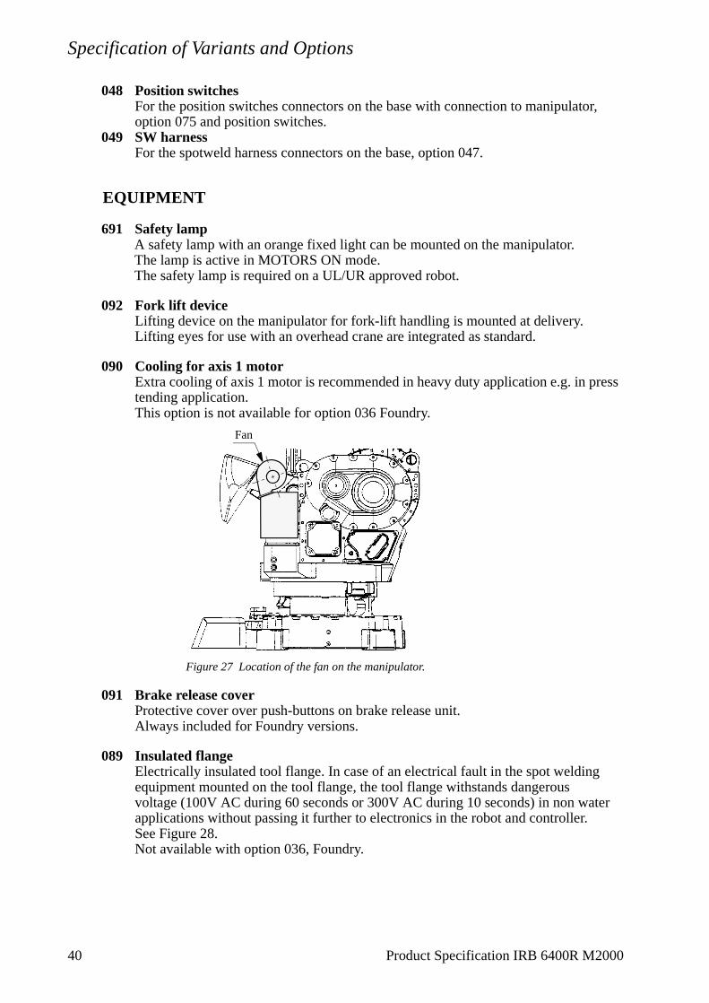
090 Cooling for axis 1 motorExtra cooling of axis 1 motor is recommended in heavy duty application e.g. in press tending application.This option is not available for option 036 Foundry.
Figure 27 Location of the fan on the manipulator.
091 Brake release coverProtective cover over push-buttons on brake release unit.Always included for Foundry versions.
089 Insulated flangeElectrically insulated tool flange. In case of an electrical fault in the spot welding equipment mounted on the tool flange, the tool flange withstands dangerous voltage (100V AC during 60 seconds or 300V AC during 10 seconds) in non water applications without passing it further to electronics in the robot and controller.See Figure 28.Not available with option 036, Foundry.
Fan
40 Product Specification IRB 6400R M2000

Specification of Variants and Options
Figure 28 The mechanical interface of the insulated flange (dimensions in mm).
POSITION SWITCHES
Position switches indicating the position of the three main axes. Rails with separate adjustable cams are attached to the manipulator. The cams, which have to be adapted to the switch function by the user, can be mounted in any position in the working range for each switch. No machining operation of the cams is necessary for the adaption, simple hand tools can be used.
For axis 1 there are three position switch functions available. For axes 2 and 3 one position switch function each.Each position switch function consists of two switches mechanically operated by separate cams. Each switch has one normal open and one normal closed contact. See the exception for axis 1.The design and components fulfill the demands to be used as safety switches.This options may require external safety arrangements, e.g. light curtains, photocells or contact mats.
The switches can be connected either to the manipulator base (R1.SW1 and R1.SW2/3, see Figure 23), or to the controller. In the controller the signals are connected to screw terminal XT8 Phoenix MSTB 2.5/12-ST-5.08. Switch type Balluff Multiple position switches BNS, according to EN 60947-5-1 and EN 60947-5-2.
Connection to075 Manipulator
Connection on the manipulator base with one/two FCI 23-pin connector.Customer connection sets for R1.SW1 and R1.SW2/3 are available as option.More information in Product Manual IRB 6400R/Installation.
076 CabinetConnection on the cabinet wall. Position switch cables are included.
Position switches axis 1069 One switch071 Three switches
30o
60o
D=10 H7 Depth 10
M10 (6x) Depth 18
D=1
60 h
7
D=
80 H
7
D=125
8
810oD=10 H7 Depth 10
Product Specification IRB 6400R M2000 41
Specification of Variants and Options
Connection of signals axis 1 (cable lengths)078 7m079 15m080 22m081 30m
072 Position switches axis 2Only available if option 041 or 042 is chosen.Not available with option 036 (foundry).
073 Position switches axis 3Only available if options 041 or 042, and 072 are chosen.Not available with option 036 (foundry).
Connection of signals axes 2 and 3 (cable lengths)083 7m084 15m085 22m086 30m
WORKING RANGE LIMIT
To increase the safety of the robot, the working range of axes 1, 2 and 3 can be restricted by extra mechanical stops.
Axis 1061 Stops which allow the working range to be restricted in increments of 7,5o.
062 Stops which allow the working range to be restricted in increments of 15o.
063 Axis 2Six stops which allow the working range to be restricted in increments of 15o at both end positions. Each stop decreases the motion by 15o.
064 Axis 3Six stops which allow the working range to be restricted in increments of 15o at both end positions. Each stop decreases the motion by 15o.
42 Product Specification IRB 6400R M2000

Accessories
3 Accessories
There is a range of tools and equipment available, specially designed for the robot.
Basic software and software options for robot and PC
For more information, see Product Specification S4Cplus, and Product Specification RobotWare Options.
Robot Peripherals
- Track Motion
- Tool System
- Motor Units
- Spot welding system for transformer gun
Product Specification IRB 6400R M2000 43

Accessories
44 Product Specification IRB 6400R M2000
Index
4 Index
A
accessories 43air supply 34application interface 22
B
brake release cover 40
C
Can/DeviceNet 36colours 33cooling device 4cooling for axis 1 motor 40customer connections 35, 36
D
dresspack examples 26
E
emergency stop 7enabling device 6equipment
mounting 15permitted extra load 15
extra equipmentconnections 34
F
fan 40fire safety 7Foundry variants 33
H
hold-to-run control 7humidity 8
I
installation 8insulated flange 40
Product Specification IRB 6400R M2000
L
lifting device 40load 8load diagrams 10
M
maintenance 19manipulator colour 33mechanical interface 18media outlet 35motion 20mounting
extra equipment 15robot 8
mounting flange 18
N
noise level 4
O
operating requirements 8options 33overspeed protection 7
P
payload 8performance 21position switches 41process media conduit 38Profibus 36protection standards 8
R
range of movement 20reduced speed 6repeatability 21Robot Gun 28Robot Gun and Track Motion 32Robot Peripherals 43robot versions 4
S
safeguarded space stop 7delayed 7
45

Index
4
safety 6safety lamp 7, 40service 19Servo Gun 27signal connections 34signals 22space requirements 4Spotweld Harness 37standards 6Stationary and Robot Gun 29Stationary Gun 27Stationary Gun and Track Motion 31structure 3
T
temperature 8troubleshooting 19Twin Stationary Guns 30
V
variants 33
W
weight 4working space
restricting 7, 8, 42
6
Product Specification IRB 6400R M2000