product manual abb i-bus eib / knx · product manual abb i-bus ... 2.1 be/m 4.230.1 binary input...
TRANSCRIPT
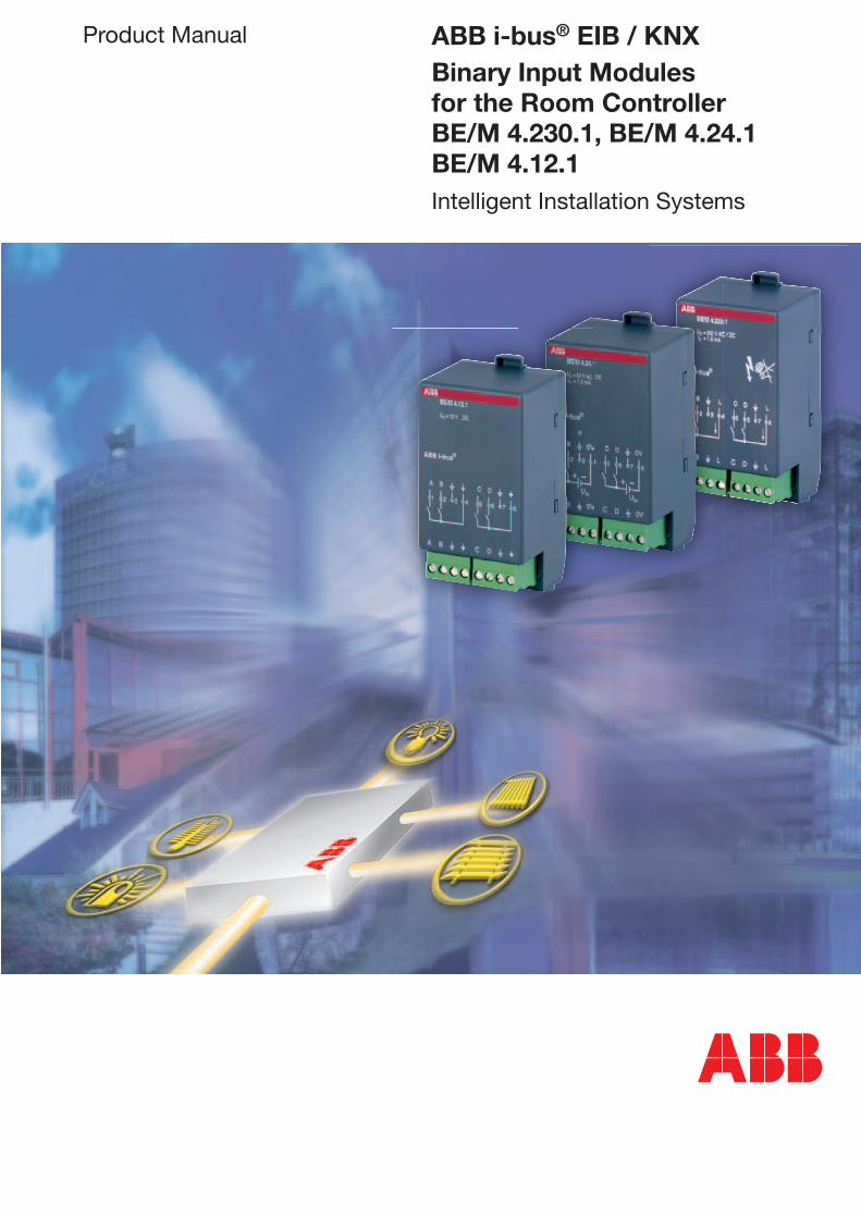
Product Manual ABB i-bus® EIB / KNXBinary Input Modules for the Room ControllerBE/M 4.230.1, BE/M 4.24.1BE/M 4.12.1Intelligent Installation Systems

This manual describes the function of the Binary Input Modules BE/M 4.230.1, BE/M 4.24.1 and BE/M 4.12.1 for operation in the Room Controller Base Unit.
Subject to changes and errors excepted.
Exclusion of liability:Despite checking that the contents of this document match the hardware and software, deviations cannot be completely excluded. We therefore cannot accept any liability for this. Any necessary corrections will be inserted in new versions of the manual.Please inform us of any suggested improvements.

Contents
1
Page
1 Introduction ........................................................................... 31.1 Functional overview ................................................................ 3
2 Device technology ................................................................. 42.1 BE/M 4.230.1 Binary Input Module, 4-fold, 230 V AC/DC ...... 42.1.1 Technical data ......................................................................... 42.1.2 Circuit diagram ........................................................................ 52.1.3 Description of the inputs ......................................................... 52.1.4 Assembly and installation ....................................................... 52.2 BE/M 4.24.1 Binary Input Module, 4-fold, 24 V AC/DC .......... 62.2.1 Technical data ......................................................................... 62.2.2 Circuit diagram ........................................................................ 72.2.3 Description of the inputs ......................................................... 72.2.4 Assembly and installation ....................................................... 72.3 BE/M 4.12.1 Binary Input Module, 4-fold, contact scanning .. 82.3.1 Technical data ......................................................................... 82.3.2 Circuit diagram ........................................................................ 92.3.3 Description of the inputs ......................................................... 92.3.4 Assembly and installation ....................................................... 9
3 Application and planning ...................................................... 103.1 Disabling the input .................................................................. 103.2 Debounce time and minimum signal time ............................... 103.3 Limitation of the telegram rate ................................................ 113.4 Cyclical sending ...................................................................... 113.5 Dimming .................................................................................. 123.6 Scene control .......................................................................... 123.7 Switching sequence ................................................................ 143.8 Counter ................................................................................... 163.9 Behaviour on voltage failure and recovery .............................. 173.10 Behaviour after programming ................................................. 17
4 Project design and programming ........................................ 184.1 Overview of the functions ....................................................... 184.2 Function: “Switch sensor” ...................................................... 194.2.1 Parameter window .................................................................. 194.2.2 Overview of the objects .......................................................... 214.2.3 Detailed description of the objects ......................................... 214.3 Function: “Switch/dimming sensor” ....................................... 224.3.1 Parameter window .................................................................. 224.3.2 Overview of the objects .......................................................... 244.3.3 Detailed description of the objects ......................................... 244.4 Function: “Shutter sensor” ...................................................... 254.4.1 Parameter window .................................................................. 254.4.2 Overview of the objects .......................................................... 274.4.3 Detailed description of the objects ......................................... 274.5 Function: “Value / forced operation” ....................................... 284.5.1 Parameter window .................................................................. 284.5.2 Overview of the objects .......................................................... 294.5.3 Detailed description of the objects ......................................... 29
2
Sei te
4.6 Function: “Control scene” ....................................................... 304.6.1 Parameter window .................................................................. 314.6.2 Overview of the objects .......................................................... 334.6.3 Detailed description of the objects ......................................... 344.7 Function: “Switching sequence” ............................................. 354.7.1 Parameter window .................................................................. 354.7.2 Overview of the objects .......................................................... 364.7.3 Detailed description of the objects ......................................... 364.8 Function: “Push button with multiple operation” .................... 374.8.1 Parameter window .................................................................. 374.8.2 Overview of the objects .......................................................... 394.8.3 Detailed description of the objects ......................................... 394.9 Function: “Counter” ................................................................ 404.9.1 Parameter window .................................................................. 404.9.2 Overview of the objects .......................................................... 424.9.3 Detailed description of the objects ......................................... 42
5 Appendix ................................................................................ 445.1 Gray code table ....................................................................... 445.2 Ordering information ............................................................... 44
Contents

3
ABB i-bus® EIB / KNX Introduction
1 Introduction
1.1 Functional overview
The Binary Input Modules BE/M 4.230.1, BE/M 4.24.1 and BE/M 4.12.1 are snapped into a module slot of the Room Controller Base Unit RC/A 8.1. They are used for reading out contacts such as conventional switches and push buttons. All the modules have four inputs each.
The Room Controller Base Unit establishes the connection to the ABB i-bus® EIB / KNX installation bus.
The BE/M 4.230.1 is used to read out 115 or 230 V AC signals. The voltage is made available by the module if required.
The BE/M 4.24.1 is used for reading out 12 V or 24 V AC/DC signals. An external 12 or 24 V power source is required.
The BE/M 4.12.1 is used for reading out floating contacts. The scanning voltage is made available by the module.
The devices have screw terminals with a plug-in connection.
The comprehensive functionality is defined by programming the Room Controller Base Unit with the EIB Tool Software (ETS2 V1.2a or higher). It is almost identical for all three devices and enables convenient, user-friendly operation via the ABB i-bus® EIB / KNX.
The following operator functions are possible with the devices described here (selection):
• Switching and dimming of lighting (also 1 button operation)
• Operation of blinds and shutters (also 1 button operation)
• Sending of values e.g. temperature values
• Control and storing of lightscenes
• Control of different loads with multiple operation
• Operation of several loads in a defined switching sequence
• Counting of pulses and operations
• Reading out of technical contacts (e.g. relays)
Each input can take over any of the functions described above.
4
ABB i-bus® EIB / KNX Device technology
2 Device technology
2.1 BE/M 4.230.1
Binary Input Module,
4-fold, 230 V AC/DC
2.1.1 Technical data
The 4-fold Binary Input Module is operated in any module slot of the Room Controller Base Unit. It has four inputs for reading out 115 V or 230 V contacts such as conventional switches and push buttons. The device makes the signal voltage available if required (incoming supply of the Room Controller).
Both the incoming supply and the internal voltage are supplied via the Room Controller Base Unit. Contact is automatically established when the modules are snapped in place.
Power supply: – Internal supply via the Room Controller Base Unit, contact made via contact system on base of module Inputs: – Number 4 – Signal level 0 ... 40 V AC / DC for 0-signal 90 ... 264 V AC / DC for 1-signal – Input current max. 2 mAConnections: – Signal cables (inputs) 2 x 4-pole screw terminals with plug-in connection – Max. cable length 100 m – Wire ranges 0.2…2.5 mm2 finely stranded 0.2…4.0 mm2 single-coreAmbient temperature range: – Storage – 25 °C ... 55 °C – Transport – 25 °C ... 70 °CDesign: – Type of installation For snapping into the Room Controller Base Unit – Housing, colour Plastic housing, anthracite, halogen-free – Housing dimensions (W x H x D) 49 x 42 x 93 – Weight 0.06 kgCE norm: – in accordance with the EMC guideline
and low voltage guideline
5
ABB i-bus® EIB / KNX
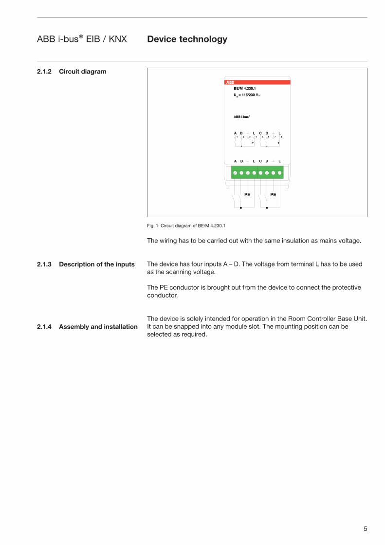
2.1.2 Circuit diagram
2.1.3 Description of the inputs
2.1.4 Assembly and installation
Fig. 1: Circuit diagram of BE/M 4.230.1
The wiring has to be carried out with the same insulation as mains voltage.
The device has four inputs A – D. The voltage from terminal L has to be used as the scanning voltage.
The PE conductor is brought out from the device to connect the protective conductor.
The device is solely intended for operation in the Room Controller Base Unit. It can be snapped into any module slot. The mounting position can be selected as required.
C
Device technology
6
ABB i-bus® EIB / KNX
2.2 BE/M 4.24.1
Binary Input Module,
4-fold, 24 V AC/DC
2.2.1 Technical data
The 4-fold Binary Input Module is operated in any module slot of the Room Controller Base Unit. It has four inputs for reading out 12 V or 24 V contacts such as conventional switches and push buttons. The signal voltage must be made available externally and linked with the reference potential.
The internal supply is carried out via the Room Controller Base Unit. Contact is established automatically when the module is snapped in place.
Power supply: – Internal supply via the Room Controller Base Unit, contact made via contact system on base of module Inputs: – Number 4 – Signal level 0...4 V AC / DC for 0 signal 9...30 V AC / DC for 1 signal – Input current max. 2 mAConnections: – Signal cables and reference potential 2 x 4-pole screw terminals with plug-in connection – Max. cable length 100 m – Wire ranges 0.2…2.5 mm2 finely stranded 0.2…4.0 mm2 single-coreAmbient temperature range: – Storage – 25 °C ... 55 °C – Transport – 25 °C ... 70 °CDesign: – Type of installation For snapping into the Room Controller Base Unit – Housing, colour Plastic housing, anthracite, halogen-free – Housing dimensions (W x H x D) 49 x 42 x 93 – Weight 0.06 kgCE norm: – in accordance with the EMC guideline
and low voltage guideline
Device technology
7
ABB i-bus® EIB / KNX Device technology
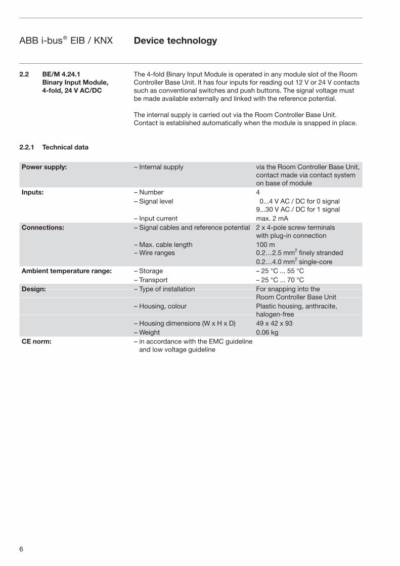
2.2.2 Circuit diagram
2.2.3 Circuit diagram
2.2.4 Assembly and installation
Fig. 2: Circuit diagram of BE/M 4.24.1
The wiring has to be carried out with the same insulation as mains voltage.
The device has four inputs A – D. The scanning voltage must be made available by an external power source. The terminal “0 V” must be used as a reference potential.
The PE conductor is brought out from the device to connect the protective conductor.
The device is solely intended for operation in the Room Controller Base Unit. It can be snapped into any module slot. The mounting position can be selected as required.
8
ABB i-bus® EIB / KNX Device technology
2.3 BE/M 4.12.1
Binary Input Module,
4-fold, contact scanning
2.3.1 Technische Daten
The 4-fold Binary Input Module is operated in any module slot of the Room Controller Base Unit. It has four inputs for reading out floating contacts such as conventional switches and push buttons. The device makes the pulsed scanning voltage (12 V) available.
The internal supply is carried out via the Room Controller Base Unit. Contact is automatically established when the module is snapped in place.
Power supply: – Internal supply via the Room Controller Base Unit, contact made via contact system on base of module Inputs: – Number 4 – Scanning voltage approx. 12 V (pulsed) – Scanning current 0.2 mA, approx. 160 mA for short periods when closingConnections: – Signal cables (inputs) 2 x 4-pole screw terminals with plug-in connection – Max. cable length 100 m – Wire ranges 0.2…2.5 mm2 finely stranded 0.2…4.0 mm2 single-coreAmbient temperature range: – Storage – 25 °C ... 55 °C – Transport – 25 °C ... 70 °CDesign: – Type of installation For snapping into the Room Controller Base Unit – Housing, colour Plastic housing, anthracite, halogen-free – Housing dimensions (W x H x D) 49 x 42 x 93 – Weight 0.06 kgCE norm: – in accordance with the EMC guideline
and low voltage guideline
9
ABB i-bus® EIB / KNX Device technology
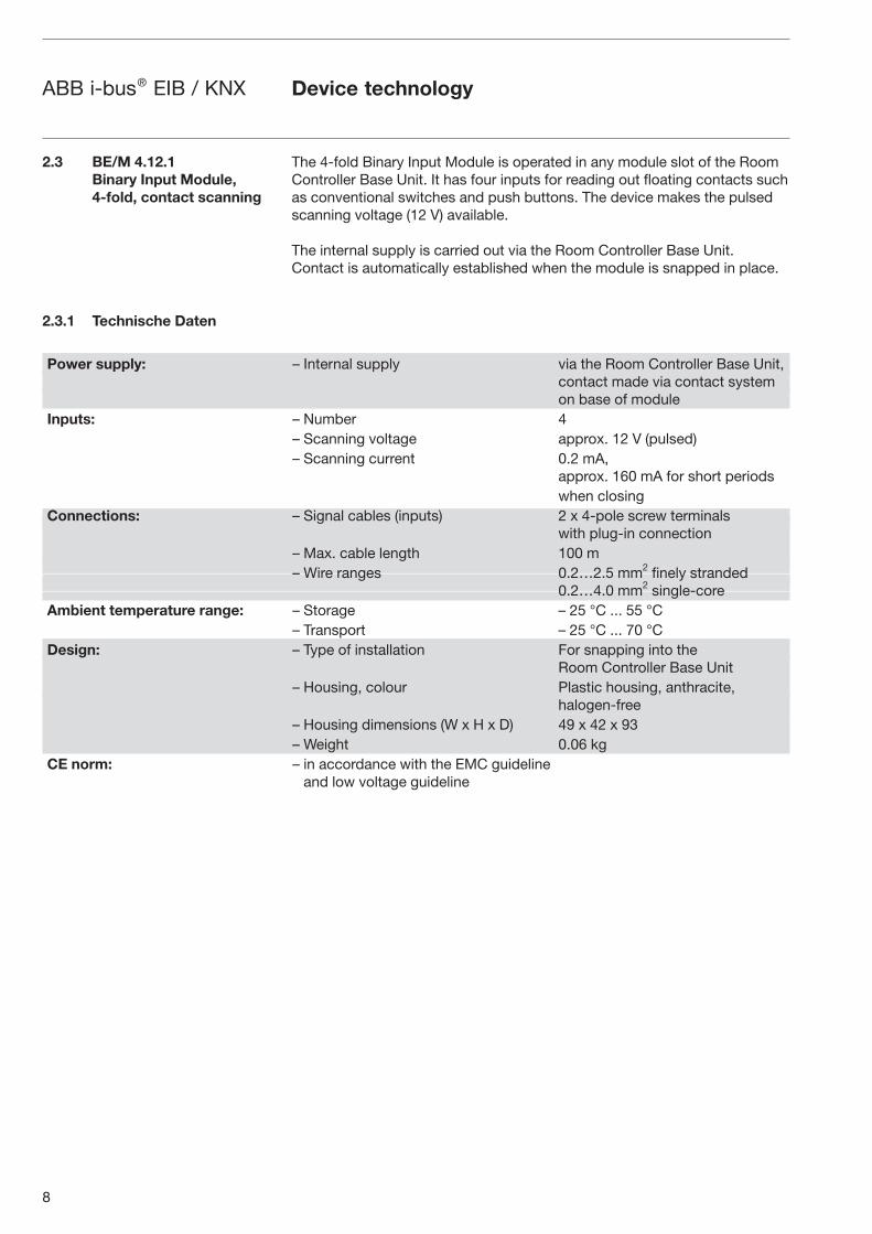
2.3.2 Circuit diagram
2.3.3 Description of the inputs
2.3.4 Assembly and installation
Fig. 3: Circuit diagram of BE/M 4.12.1
The wiring has to be carried out with the same insulation as mains voltage.
The device has four inputs A – D. The positive, pulsed scanning voltage is made available by the terminal “�”.
The PE conductor is brought out from the device to connect the protective conductor.
The device is solely intended for operation in the Room Controller Base Unit. It can be snapped into any module slot. The mounting position can be selected as required.
10
ABB i-bus® EIB / KNX Application and planning
3 Application and planning
3.1 Disabling the input
3.2 Debounce time and
minimum signal time
Certain features are explained in more detail in this section.
Each input can be enabled or disabled via the object “Disable”. A disabled input behaves as if no change in the input signal had taken place. The objects of the input remain available.
Values of the object “Disable”:
Telegram value “0”: Enable input “1”: Disable input
When a disabled input is enabled, no telegrams are sent initially on the bus, even if the status of the input has changed while it was deactivated. If the input is operated once it has been enabled, the input behaves as if the operation had started at the end of the deactivation. If the input is disab-led during an operation, the behaviour is undefined.
It is possible to set a debounce time or a minimum signal time for each input.
Debounce time
If a pulse edge is detected at the input, the input reacts to it immediately (e.g. by sending a telegram). The debounce time TD starts simultaneously. The signal at the input is not evaluated within the debounce period.
The following example clarifies this:
Fig. 4: Debouncing of an input signal
Once a pulse edge has been detected at the input, further edges are ignored for the duration of the debounce time TD.
11
ABB i-bus® EIB / KNX Application and planning
Minimum signal time
This function is distinguished from the debounce time in that the telegram is only sent once the minimum signal time has elapsed. The function is as follows:
If a pulse edge is detected at the input, the minimum signal time starts. No telegrams are sent on the bus at this point. The signal at the input is then observed. If a further pulse edge occurs at the input during the minimum signal time, this is interpreted as a new operation and the minimum signal time is restarted if necessary. If the input signal has not changed during the minimum signal time, a pulse edge is detected and a telegram is sent on the bus if necessary.
The following example clarifies this:
Fig. 5: Processing of a signal with minimum signal time
Since only two pulse edges remain stable for the duration of the minimum signal time TM, only these pulse edges are recognised as valid.
A new observation period starts after the end of the previous observation period or – in the event of a bus voltage recovery – after the end of the transmission delay. The transmitted telegrams are counted. As soon as the “Max. number of transmitted telegrams…” has been reached, no further telegrams are sent on the bus until the end of the observation period. With the start of a new observation period, the telegram counter is reset to zero and the sending of telegrams is permitted again.
Cyclical sending is part of the “Switch sensor” function. It enables the “Telegr. switch” object to send automatically at a fixed interval.
If cyclical sending is only carried out for a specific object value (ON or OFF), this condition refers to the value of the communication object. It is therefore possible in principle to start the cyclical sending by sending a value to the “Telegr. switch” object.
If this reaction is unwanted, the “write” flag of the object “Telegr. switch” has to be deleted.
3.3 Limitation of the
telegram rate
3.4 Cyclical sending

12
ABB i-bus® EIB / KNX Application and planning
When the “Telegr. switch” object changes and after bus voltage recovery (once the transmission delay has elapsed), the object value is sent immedia-tely on the bus and the transmission cycle time restarts. The minimum value for the cyclic period is 200 ms. If a smaller value is set in the parameters, the transmission cycle time is equal to the minimum value.
The “1 button dimming” function is set as default i.e. switching and dimming functions can be fully controlled via a single push button. A “Dim BRIGHTER” or “Dim DARKER” telegram is therefore sent alternately after each dimming operation. If the “Telegr. switch” object = 0, a “Dim BRIGHTER” telegram is always sent. To enable the evaluation of the status response of the actuator, the “Write” flag of the “Telegr. switch” object is set.
The following table explains the function in detail:
Value of the “Telegr.
switch” object
Value of the last
dimming telegram
Reaction to the dimming operation
(dimming telegram sent)
OFF DARKER BRIGHTER
OFF BRIGHTER BRIGHTER
ON DARKER BRIGHTER
ON BRIGHTER DARKER
Table 1: Dimming function on “1 button dimming”
If “2 button dimming” is required, the function of the individual push button must be set in the parameters “Reaction on short operation” or “Reaction on long operation” (e.g. “ON” or “Dim BRIGHTER”). The user thus has comple-te freedom to choose• which push buttons are combined with each other in order to dim a group
of luminaires
• which function the individual push button has in this case
A scene button regulates actuators (e.g. dimming actuators or shutter actuators) to a preset value via a single operation. For example, it can be used to set appropriate lighting conditions.
Moreover, the push button can store the current actuator values as a new scene via long push button action. A scene can thus be adapted in a simple way.
3.5 Dimming
3.6 Scene control
13
ABB i-bus® EIB / KNX Application and planning
A scene can be implemented in two different ways:
Fig. 6: Recall scene, separate objects
One input recalls up to 5 actuator groups. Up to 5 telegrams can thus be sent.
An actuator group comprises several actuators that are linked with the same group address. It can consist of e.g. switch actuators (1-bit values) or dimming actuators (1-byte values).
Fig. 7: Store scene, separate objects
The storing of a scene is carried out with a long push button action. The device scans each individual actuator group for the current value and then stores this value as the new scene value.

14
ABB i-bus® EIB / KNX
Fig. 8: Recall scene, 8-bit scene
In the 8-bit scene, the push button gives the actuator the instruction to recall a scene. The scene is stored not in the push button but in the actuator. All the actuators are addressed via the same group address. A single telegram is sufficient to recall the scene.
The telegram value contains a scene number which must match the scene number in the parameters of the actuator.
Up to 64 different scenes are managed via a single group address. An 8-bit scene telegram contains the following information:
– Number of the scene (1...64)
– Recall scene / store scene
After a long push button action, the actuators receive a save command which causes them to store the currently issued value as a new scene value.
Fig. 9: Example of switching sequence with two objects (corresponds to binary code)
Application and planning
3.7 Switching sequence
15
ABB i-bus® EIB / KNX
The “Switching sequence” function enables up to five objects (1 bit) to be switched on or off in a defined sequence. The sequence is switched one level further after each operation.
Example: Switching sequence “sequentially on/off (one push button)” with three communication objects
Switching level Value of the communication objects
Input operation no. Binary code “Switch 3” “Switch 2” “Switch 1”
1 001 OFF OFF ON
2 011 OFF ON ON
3 111 ON ON ON
4 011 OFF ON ON
5 001 OFF OFF ON
6 000 OFF OFF OFF
7 = 1 001 OFF OFF ON
...
All the switch objects are switched on in succession and switched off again one after the other, starting with the last switch object that was switched on. Binary code: ...>001>011>111>011>001>000>...
The possible switching sequences are characterised by the fact that only the value of a single communication object changes between two switching levels. The following switching sequences are possible:
“Sequentially on/off (one push button)”
This switching sequence switches on a further communication object in succession after each operation. If all the objects are switched on, they are switched off again one after the other – starting with the last object that was switched on.
“Sequentially on/off, several push buttons”
This switching sequence is only distinguished from the previous one in that the sequence ignores further operations as soon as it has arrived at the end. At least two inputs are therefore required, one of which switches up a level and the other switches down a level in the sequence.
Note: The objects of the inputs must have the same group address assignments.
“All combinations (“Gray code”)”
This switching sequence runs through all the combinations of the communi-cation objects in succession. Only the value of one communication object is changed between two switching levels. A clear application of this switching sequence is e.g. the switching of two groups of luminaires in the sequence 00 – 01 – 11 – 10 – 00 ...
You can find a ‘Gray code table’ in the appendix under section 5.1.
Application and planning
16
ABB i-bus® EIB / KNX
Further options
The switching level can be modified both via the operation of the input and via the communication object “Level increment/decrement”. This object is used for example to switch upwards or downwards with two or more inputs.
Note: The current switching level is always produced from the status of the objects. If e.g. an object is modified by another device, the current switching level can also be changed as a result.
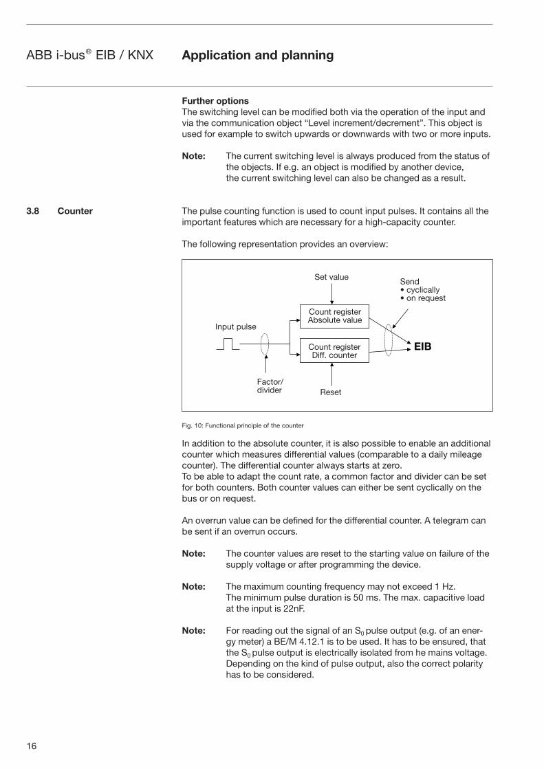
The pulse counting function is used to count input pulses. It contains all the important features which are necessary for a high-capacity counter.
The following representation provides an overview:
Fig. 10: Functional principle of the counter
In addition to the absolute counter, it is also possible to enable an additional counter which measures differential values (comparable to a daily mileage counter). The differential counter always starts at zero. To be able to adapt the count rate, a common factor and divider can be set for both counters. Both counter values can either be sent cyclically on the bus or on request.
An overrun value can be defined for the differential counter. A telegram can be sent if an overrun occurs.
Note: The counter values are reset to the starting value on failure of the supply voltage or after programming the device.
Note: The maximum counting frequency may not exceed 1 Hz. The minimum pulse duration is 50 ms. The max. capacitive load at the input is 22nF.
Note: For reading out the signal of an S0 pulse output (e.g. of an ener-gy meter) a BE/M 4.12.1 is to be used. It has to be ensured, that the S0 pulse output is electrically isolated from he mains voltage. Depending on the kind of pulse output, also the correct polarity has to be considered.
Application and planning
3.8 Counter
Set value
Input pulse
Factor/divider Reset
Send• cyclically• on request
Count registerAbsolute value
Count registerDiff. counter
17
ABB i-bus® EIB / KNX Application and planning
3.9 Behaviour on voltage
failure and recovery
3.10 Behaviour after
programming
Behaviour on bus voltage failure
On bus voltage failure, the device function is retained provided that the supply voltage of the Room Controller is maintained. The inputs can there-fore be used to operate the outputs, provided that the associated actuator modules are mounted in the same Room Controller.
Behaviour after bus voltage recovery
On bus voltage recovery, the inputs are scanned after the initialization period and the object values are updated accordingly, provided that this is permit-ted in the function or parameters.
The behaviour is dependent on the function of the channel. The following list provides an overview:
Function Behaviour after bus voltage recovery*
Switch sensor If a distinction is made between a long and short operation or the value “TOGGLE” has been set in one of the parameters “Reaction on opening/closing the contact”, no telegrams are sent after bus voltage recovery.
Otherwise, the behaviour can be set in the parameters.
Switch/dimming sensor No telegrams are sent on the bus.
Shutter sensor No telegrams are sent on the bus.
Value / forced operation Object values are overwritten by the parameterised values.
Control scene When the scene is controlled via “5 separate objects”, the object values of the scene are overwritten with the paramete-rised values.
Switching sequence (“latching relay”)
No telegrams are sent on the bus.
Push button with multiple operation
No telegrams are sent on the bus.
Counter No telegrams are sent on the bus.
*More accurate: Behaviour in connection with the transmission delay
You can find further details about the behaviour after bus voltage recovery in the manual for the Room Controller.
Behaviour on failure of the supply voltage
If the supply voltage of the Room Controller fails, the modules also no longer continue to function. This is the case regardless of whether the bus voltage is applied.
Behaviour after recovery of the supply voltage
If the supply voltage of the Room Controller Base Unit is connected to the system, the device behaves in the same way as after bus voltage recovery.
After programming, the device behaves as after bus voltage recovery.
18
ABB i-bus® EIB / KNX Project design and programming
4 Project design and programming
4.1 Overview of the functions The Room Controller has its own application program “Room Controller modular, 8f/1”, which is used to set the device function. The programming requires EIB Tool Software ETS2 V1.3a or higher.
The following functions can be set separately for each input:
Switch sensor For switching the lighting or scanning a floating contact (relay)
Distinction between short/long operation and cyclical sending of the contact state are possible.
Switch/dimming sensor For switching/dimming the lighting
Start-stop dimming and stepwise dimming as well as dimming via a single push button are possible.
Shutter sensor For movement/lamella adjustment of a blind or a shutter
Eight preset operating responses are possible in total.
Value / forced operation For sending values of different data types (e.g. temperature values)
It is possible to send different values or data types after a short/long operation. The activation/deactivation of the priority control of actuators is also possible.
Control scene For recalling and storing the states of several actuator groups
The actuator groups can either be controlled via 5 individual objects or (if supported by the actuators) via a special 8-bit scene object.
Switching sequence
(“latching relay”)
For the operation of several actuator groups in preset sequences
Push button with
multiple operation
For triggering various functions depending on the frequency of operation
A long operation can be also be detected and trigger a function.
Counter For counting input pulses
Different data types can be set for the counter. An additional differential counter enables the counting of daily values for example. A factor/divider enables different count rates.
Application program Number of Max. number of Max. number of
communication objects group addresses associations
Room Controller modular, 8f/1 246 254 255
19
ABB i-bus® EIB / KNX Project design and programming
4.2 “Switch sensor”
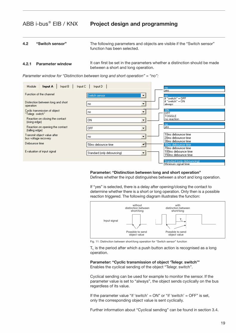
4.2.1 Parameter window
The following parameters and objects are visible if the “Switch sensor” function has been selected.
It can first be set in the parameters whether a distinction should be made between a short and long operation.
Parameter: “Distinction between long and short operation”
Defines whether the input distinguishes between a short and long operation.
If “yes” is selected, there is a delay after opening/closing the contact to determine whether there is a short or long operation. Only then is a possible reaction triggered. The following diagram illustrates the function:
Fig. 11: Distinction between short/long operation for “Switch sensor” function
TL is the period after which a push button action is recognised as a long operation.
Parameter: “Cyclic transmission of object ‘Telegr. switch’”
Enables the cyclical sending of the object “Telegr. switch”.
Cyclical sending can be used for example to monitor the sensor. If the parameter value is set to “always”, the object sends cyclically on the bus regardless of its value.
If the parameter value “if ‘switch’ = ON” or “if ‘switch’ = OFF” is set, only the corresponding object value is sent cyclically.
Further information about “Cyclical sending” can be found in section 3.4.
Parameter window for “Distinction between long and short operation” = “no”:
withoutdistinction between
short/long
withdistinction between
short/long
Possible to sendobject value
Possible to sendobject value
Input signal

20
ABB i-bus® EIB / KNX Project design and programming
Parameter: “Reaction on closing the contact (rising edge)” or “Reaction
on opening the contact (falling edge)”
Defines the reaction of the object “Telegr. switch” if a pulse edge is detected at the input.
It can be set for each edge whether the object value should be switched “ON”, “OFF” or toggled or whether there should be no reaction.
If cyclical sending is parameterised, it is possible by selecting the parameter value “terminate cyclic transmission” for an operation of the input to end cyclical sending without a new object value being sent. The parameter is visible if there is no distinction between a short and long operation.
Parameter: “Telegram is repeated every (‘transmission cycle time’)”
Defines the intervals at which the object value “Telegr. switch” is sent. The parameter is visible if cyclical sending has been set.
Parameter: “Transmit object value after bus voltage recovery”
Causes the sending of the object “Telegr. switch” after bus voltage recovery.
A value is only sent on the bus if the value “TOGGLE” has not been set in either of the two parameters “Reaction on opening/closing the contact (...)”. If one of the two parameters has the value “TOGGLE”, no values are generally sent on the bus after bus voltage recovery.
Parameter: “Debounce time”
Debouncing prevents unwanted multiple operation of the input e.g. due to bouncing of the contact. Refer to section 3.2 for the precise function of this parameter.
Parameter: “Evaluation of input signal”
Used for setting a minimum signal time.
After a pulse edge, the input waits for the minimum signal time. Only if no further edge occurs during this period is a change in the pulse edge valid. If a further transition occurs, the minimum signal time restarts. The minimum signal time can be set separately for the rising and falling edge. Further information can be found in section 3.2.
The parameter is visible if there is no distinction between a short and long operation.
Parameter window for “Distinction between short and long operation” = “yes”:
21
ABB i-bus® EIB / KNX
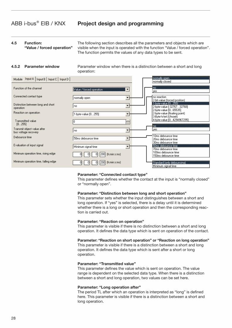
Parameter: “Connected contact type”
Defines whether the contact at the input is “normally open” or “normally closed”.
Parameter: “Reaction on short operation” or “Reaction on long operation”
Defines the reaction of the object “Telegr. switch” when a short or long operation is detected at the input.
The object value is updated as soon as it is established whether there is a short or long operation.
Parameter: “Long operation after”
Defines the period TL after which an operation is interpreted as “long” (see Fig. 1).
Parameter: “Number of objects for short/long operation”
Enables the additional object “Telegr. switch –long”.
This object only sends after a long operation while “Telegr. switch” only reacts to a short operation.
Parameter: “Debounce time”
Debouncing prevents unwanted multiple operation of the input e.g. due to bouncing of the contact. Refer to section 3.2 for the precise function of this parameter.
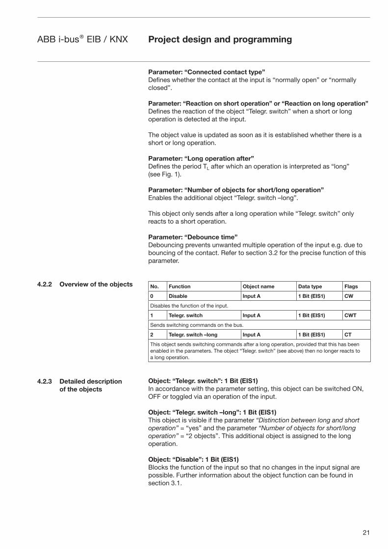
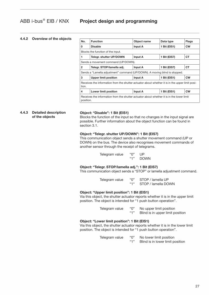
No. Function Object name Data type Flags
0 Disable Input A 1 Bit (EIS1) CW
Disables the function of the input.
1 Telegr. switch Input A 1 Bit (EIS1) CWT
Sends switching commands on the bus.
2 Telegr. switch –long Input A 1 Bit (EIS1) CT
This object sends switching commands after a long operation, provided that this has been enabled in the parameters. The object “Telegr. switch” (see above) then no longer reacts to a long operation.
Object: “Telegr. switch”: 1 Bit (EIS1)
In accordance with the parameter setting, this object can be switched ON, OFF or toggled via an operation of the input.
Object: “Telegr. switch –long”: 1 Bit (EIS1)
This object is visible if the parameter “Distinction between long and short operation” = “yes” and the parameter “Number of objects for short/long operation” = “2 objects”. This additional object is assigned to the long operation.
Object: “Disable”: 1 Bit (EIS1)
Blocks the function of the input so that no changes in the input signal are possible. Further information about the object function can be found in section 3.1.
4.2.2 Overview of the objects
4.2.3 Detailed description
of the objects
Project design and programming

22
ABB i-bus® EIB / KNX
The following section describes all the parameters and objects which are visible when the input is operated with the function “Switch/dimming sensor”. The function enables the control of dimmable lighting. 1 button operation is possible.
Further details about the dimming function can be found in section 3.5.
Parameter: “Connected contact type”
Defines whether the contact at the input is “normally closed” or “normally open”.
Parameter: “Dimming functionality”
Defines whether the lighting is only dimmed (“Only dimming”) or whether it should also be switched (“Dimming and switching”). In this case, the lighting is dimmed via a long operation and switched via a short operation.
The benefit of the setting “Only dimming” lies in that there is no distinction between a short and long operation. The dimming command is therefore carried out immediately after operation as the device does not first wait to determine whether it is a long push button action.
Parameter: “Reaction on short operation”
Defines how a short operation changes the value of the object “Telegr. switch”.
This parameter sets whether the object “Telegr. switch” is toggled after a short operation (typically: 1 button dimming) or only switched OFF or ON (typically: 2 button dimming).
This parameter is visible if the value “Dimming and switching” has been set in the parameter “Dimming functionality”.
Project design and programming
4.3 Function:
“Switch/dimming sensor
4.3.1 Parameter window

23
ABB i-bus® EIB / KNX Project design and programming
Parameter: “Reaction on long operation”
Defines how a long operation changes the value of the object “Telegr. dimming”.
This parameter sets whether the object “Telegr. dimming” sends a “Dim BRIGHTER” or “Dim DARKER” telegram after a long operation. For 1 button dimming, the parameter value “Dim BRIGHTER/DARKER” must be set. In this case, the opposite dimming command to the last command is sent. This parameter is visible if the value “Dimming and switching” has been set in the parameter “Dimming functionality”.
Parameter: “Reaction on operation”
This parameter sets which value is sent by the object “Telegr. dimming” after an operation. This parameter is visible if the dimming functionality “Only dimming” has been set.
Parameter: “Long operation after”
Defines the period TL after which an operation is interpreted as “long”. This parameter is visible if the value “Dimming and switching” has been set in the parameter “Dimming functionality”.
Parameter: “Dimming mode”
The “Start-stop dimming” or “Dimming steps” dimming mode is selected here.
Normal “Start-stop dimming” starts the dimming process with a “Dim BRIGHTER” or “Dim DARKER” telegram and ends the dimming process with a “STOP” telegram. In this case, no cyclical sending of the dimming telegram is necessary.
For “Dimming steps”, the dimming telegram is sent cyclically after a long operation. After the end of an operation, a “STOP” telegram ends the dim-ming process.
Parameter: “Brightness change on every sent telegram”
This parameter is only visible when “Dimming steps” is selected. It can be set which brightness change (in percentage) causes a dimming telegram to be sent cyclically.
Parameter: “Transmission cycle time: telegram is repeated every”
If “Dimming steps” is set, the dimming telegram is sent cyclically during a long operation. The transmission cycle time corresponds to the time interval between two telegrams during the cyclical sending.
Parameter: “Debounce time”
Debouncing prevents unwanted multiple operation of the input e.g. due to bouncing of the contact. Refer to section 3.2 for the precise function of this parameter.
24
ABB i-bus® EIB / KNX
No. Function Object name Data type Flags
0 Disable Input A 1 Bit (EIS1) CW
Blocks the function of the input.
1 Telegr. switch Input A 1 Bit (EIS1) CWT
Sends switching commands (ON or OFF) on the bus after a short operation.
2 Telegr. dimming Input A 4 Bit (EIS2) CT
Sends dimming commands (BRIGHTER / DARKER or STOP) after a long operation.
Object: “Disable”: 1 Bit (EIS1)
Blocks the function of the input so that no changes in the input signal are possible. Further information about the object function can be found in section 3.1.
Object: “Telegr. switch”: 1 Bit (EIS1)
This object is visible if the value “Dimming and switching” has been set in the parameter “Dimming functionality”.
In accordance with the parameter setting, this object can be switched ON, OFF or toggled after a short operation. For 1 button dimming, this object should not be linked with the status feedback of the dimming actuator as a non-sending group address. The input is thus informed about the current switching state of the dimming actuator.
Object: “Telegr. dimming”: 4 Bit (EIS2)
A long operation of the input causes a “Dim BRIGHTER” or “Dim DARKER” command to be sent on the bus. A “STOP” command is sent at the end of the operation.
Project design and programming
4.3.2 Overview of the objects
4.3.3 Detailed description
of the objects
25
ABB i-bus® EIB / KNX Project design and programming
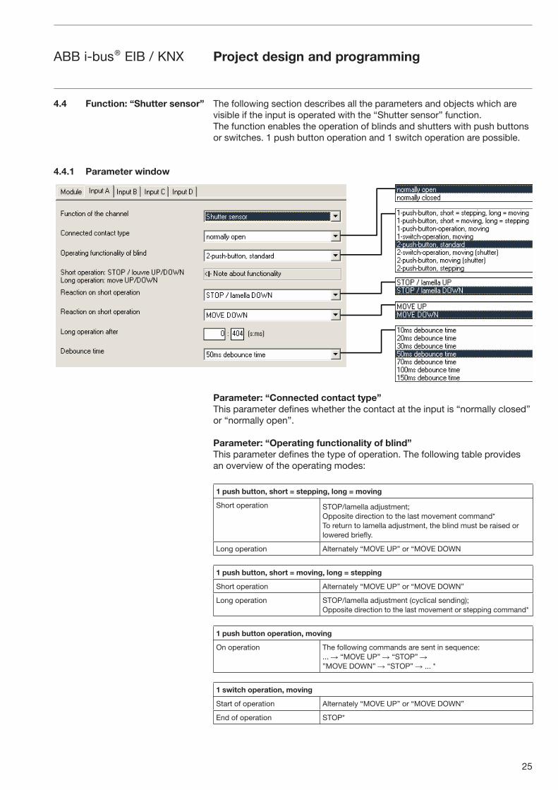
4.4 Function: “Shutter sensor”
4.4.1 Parameter window
The following section describes all the parameters and objects which are visible if the input is operated with the “Shutter sensor” function. The function enables the operation of blinds and shutters with push buttons or switches. 1 push button operation and 1 switch operation are possible.
Parameter: “Connected contact type”
This parameter defines whether the contact at the input is “normally closed” or “normally open”.
Parameter: “Operating functionality of blind”
This parameter defines the type of operation. The following table provides an overview of the operating modes:
1 push button, short = stepping, long = moving
Short operation STOP/lamella adjustment;Opposite direction to the last movement command*To return to lamella adjustment, the blind must be raised or lowered briefly.
Long operation Alternately “MOVE UP” or “MOVE DOWN
1 push button, short = moving, long = stepping
Short operation Alternately “MOVE UP” or “MOVE DOWN”
Long operation STOP/lamella adjustment (cyclical sending); Opposite direction to the last movement or stepping command*
1 push button operation, moving
On operation The following commands are sent in sequence: ... � “MOVE UP” � “STOP” � ”MOVE DOWN” � “STOP” � ... *
1 switch operation, moving
Start of operation Alternately “MOVE UP” or “MOVE DOWN”
End of operation STOP*
26
ABB i-bus® EIB / KNX Project design and programming
* Note: If the actuator is in the limit position (see objects “Upper limit position” or “Lower limit position”), the direction of movement is preselected.
In “1 push button/switch operation”, the last direction of movement is determined via the last update of the object “Telegr. shutter UP/DOWN”.
2 push button, standard
Short operation “STOP/lamella UP” or “... DOWN” (parameterisable
Long operation “MOVE UP” or “MOVE DOWN” (parameterisable)
2 switch operation, moving (shutter)
Start of operation “MOVE UP” or “MOVE DOWN” (parameterisable)
End of operation “STOP” or “... DOWN“ (parameterisable)
2 push button, moving (shutter)
On operation The following commands are sent in sequence:... � “MOVE UP” � “STOP” � ”MOVE DOWN” � “STOP” � ... *
2 push button, stepping
On operation “Lamella UP” or “... DOWN” (parameterisable)
Parameter: “Reaction on operation”
This parameter is visible if there is no distinction between a short and long operation. It can be set whether the input triggers commands for movement upwards (“UP”) or downwards (“DOWN”).
Parameter: “Reaction on short operation” or “Reaction on long operation”
This parameter is visible in operating modes in which there is a distinction between a short and long operation. It can be set whether the input triggers commands for movement upwards (“UP”) or downwards (“DOWN”).
Parameter: “Long operation after”
This parameter is visible in operating modes in which there is a distinction between a short and long operation. The period after which an operation is interpreted as “long” is defined here.
Parameter: “‘Telegram STOP/lamella adj.’ is repeated every”
This parameter is visible in operating modes in which the object “Telegr. STOP/lamella adj.” is sent cyclically on the bus during a long operation. The interval between two telegrams is set here.
Parameter: “Debounce time”
Debouncing prevents unwanted multiple operation of the input e.g. due to bouncing of the contact. Refer to section 3.2 for the precise function of this parameter.
27
ABB i-bus® EIB / KNX Project design and programming
No. Function Object name Data type Flags
0 Disable Input A 1 Bit (EIS1) CW
Blocks the function of the input.
1 Telegr. shutter UP/DOWN Input A 1 Bit (EIS7) CT
Sends a movement command (UP/DOWN).
2 Telegr. STOP/lamella adj. Input A 1 Bit (EIS7) CT
Sends a “Lamella adjustment” command (UP/DOWN). A moving blind is stopped.
3 Upper limit position Input A 1 Bit (EIS1) CW
Receives the information from the shutter actuator about whether it is in the upper limit posi-tion.
4 Lower limit position Input A 1 Bit (EIS1) CW
Receives the information from the shutter actuator about whether it is in the lower limit position.
Object: “Disable”: 1 Bit (EIS1)
Blocks the function of the input so that no changes in the input signal are possible. Further information about the object function can be found in section 3.1.
Object: “Telegr. shutter UP/DOWN”: 1 Bit (EIS7)
This communication object sends a shutter movement command (UP or DOWN) on the bus. The device also recognises movement commands of another sensor through the receipt of telegrams.
Telegram value “0” UP “1” DOWN
Object: “Telegr. STOP/lamella adj.”: 1 Bit (EIS7)
This communication object sends a “STOP” or lamella adjustment command.
Telegram value “0” STOP / lamella UP “1“ STOP / lamella DOWN
Object: “Upper limit position”: 1 Bit (EIS1)
Via this object, the shutter actuator reports whether it is in the upper limit position. The object is intended for “1 push button operation”.
Telegram value “0” No upper limit position “1” Blind is in upper limit position
Object: “Lower limit position”: 1 Bit (EIS1)
Via this object, the shutter actuator reports whether it is in the lower limit position. The object is intended for “1 push button operation”.
Telegram value “0” No lower limit position “1” Blind is in lower limit position
4.4.2 Overview of the objects
4.4.3 Detailed description
of the objects
28
ABB i-bus® EIB / KNX Project design and programming
4.5 Function:
“Value / forced operation”
4.5.2 Parameter window
The following section describes all the parameters and objects which are visible when the input is operated with the function “Value / forced operation”. The function permits the values of any data types to be sent.
Parameter window when there is a distinction between a short and long operation:
Parameter: “Connected contact type”
This parameter defines whether the contact at the input is “normally closed” or “normally open”.
Parameter: “Distinction between long and short operation”
This parameter sets whether the input distinguishes between a short and long operation. If “yes” is selected, there is a delay until it is determined whether there is a long or short operation and then the corresponding reac-tion is carried out.
Parameter: “Reaction on operation”
This parameter is visible if there is no distinction between a short and long operation. It defines the data type which is sent on operation of the contact.
Parameter: “Reaction on short operation” or “Reaction on long operation”
This parameter is visible if there is a distinction between a short and long operation. It defines the data type which is sent after a short or long operation.
Parameter: “Transmitted value”
This parameter defines the value which is sent on operation. The value range is dependent on the selected data type. When there is a distinction between a short and long operation, two values can be set here.
Parameter: “Long operation after”
The period TL after which an operation is interpreted as “long” is defined here. This parameter is visible if there is a distinction between a short and long operation.
29
ABB i-bus® EIB / KNX Project design and programming
Parameter: “Transmit object value after bus voltage recovery”
This parameter sets whether the object “Telegr. value” is sent on the bus after bus voltage recovery. This parameter is visible if there is no distinction between a short and long operation.
Parameter: “Debounce time”
Debouncing prevents unwanted multiple operation of the input e.g. due to bouncing of the contact. Refer to section 3.2 for the precise function of this parameter.
Parameter: “Evaluation of input signal”
Used for setting a minimum signal time.
After a pulse edge, the input waits for the minimum signal time. The change at the pulse edge is only valid if a further transition occurs during this period. If a further pulse edge occurs, the minimum signal time is restarted. The minimum signal time can be set separately for the rising and falling edge. Further information about the function can be found in section 3.2.
This parameter is visible if there is no distinction between a short and long operation.
No. Function Object name Data type Flags
0 Disable Input A 1 Bit (EIS1) CW
Blocks the function of the input.
1 Telegr. value […] Input A 1 Bit …
4 Byte
CT
Sends a value on the bus when it is operated. Different data types can be parameterised.
1 Telegr. value […] Input A –short 1 Bit …
4 Byte
CT
Sends a value on the bus after a short operation. Different data types can be parameterised.
2 Telegr. value […] Input A –long 1 Bit …
4 Byte
CT
Sends a value on the bus after a long operation. Different data types can be parameterised.
Object: “Disable”: 1 Bit (EIS1)
Blocks the function of the input so that no changes in the input signal are possible. Further information about the object function can be found in section 3.1.
Object: “Telegr. value (...)” (various data types)
Sends a value on the bus when the contact is opened or closed. The value and data type can be freely selected in the parameters.
4.5.2 Overview of the objects
4.5.3 Detailed description
of the objects

30
ABB i-bus® EIB / KNX Project design and programming
The following table provides an overview of the available data types:
Data width, type Value range EIS type Typical application
1 bit 0, 1 EIS 1 Switching command
2 bit 0, 2, 3 EIS 8 Forced position
1 byte without sign 0...255 EIS 6 Brightness value, positioning value
2 byte, integer value,with sign
-32768...+32767 EIS 10 Counter value
2 byte, integer value,without sign
0...65535 EIS 10 Counter value
2 byte, floating point value* -100...+100 EIS 5 Temperature values
3 byte, time 0:0:0 ... 23:23:59 EIS 3 Fixed time value
4 byte, integer value, without sign
0...4294967295 EIS 11 Counter value
*Sends values with the fixed exponent of 3
When there is a distinction between a short and long operation, 2 objects are visible per input. One object only sends after a short operation while the other object only sends after a long operation.
Note: By default, the “Write” flag is deleted for the objects (exception: for 1-bit objects). The object value can thus not be modified via the EIB. If this function is required, the “Write” flag must be set in ETS. On bus voltage recovery, the object value is overwritten with the parameterised value.
The following section describes all the parameters and objects which are visible when the input is operated with the function “Control scene”.
Two different types of scenes are possible:
Scene via 5 separate objects
Five communication objects control up to 5 actuator groups (e.g. groups of luminaires) directly. Each actuator group can be controlled in a different way. The values of the scene are stored in the input. When recalling the scene, up to 5 objects are sent. Further information can be obtained in section 3.6.
8-bit scene
A communication object sends a scene number. This number is assigned to an unlimited number of actuators. On receipt, the values that are stored in the actuators are recalled. Only one object is therefore sent on retrieval.
Both scene types enable the storing of the current output states of the actuators as new scene values. Further information can be obtained in section 3.6.
4.6 Function: “Control scene”
31
ABB i-bus® EIB / KNX Project design and programming
4.6.2 Parameter window
(remaining parameters as above)
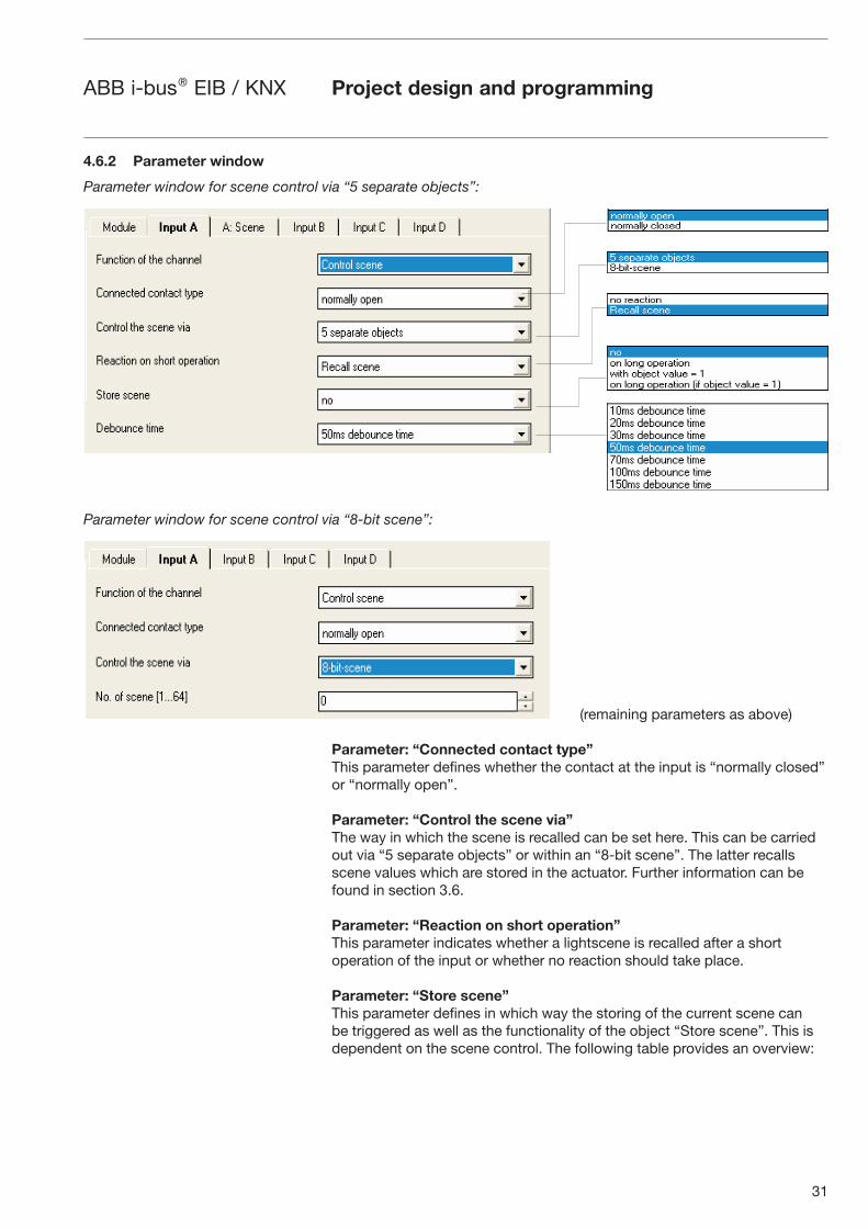
Parameter: “Connected contact type”
This parameter defines whether the contact at the input is “normally closed” or “normally open”.
Parameter: “Control the scene via”
The way in which the scene is recalled can be set here. This can be carried out via “5 separate objects” or within an “8-bit scene”. The latter recalls scene values which are stored in the actuator. Further information can be found in section 3.6.
Parameter: “Reaction on short operation”
This parameter indicates whether a lightscene is recalled after a short operation of the input or whether no reaction should take place.
Parameter: “Store scene”
This parameter defines in which way the storing of the current scene can be triggered as well as the functionality of the object “Store scene”. This is dependent on the scene control. The following table provides an overview:
Parameter window for scene control via “5 separate objects”:
Parameter window for scene control via “8-bit scene”:
32
ABB i-bus® EIB / KNX
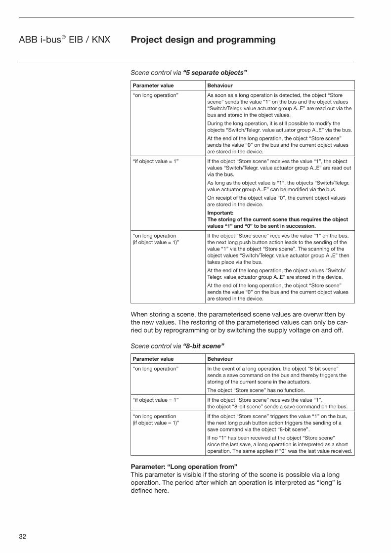
Scene control via “5 separate objects”
Parameter value Behaviour
“on long operation” As soon as a long operation is detected, the object “Store scene” sends the value “1” on the bus and the object values “Switch/Telegr. value actuator group A..E” are read out via the bus and stored in the object values.
During the long operation, it is still possible to modify the objects “Switch/Telegr. value actuator group A..E” via the bus.
At the end of the long operation, the object “Store scene” sends the value “0” on the bus and the current object values are stored in the device.
“if object value = 1” If the object “Store scene” receives the value “1”, the object values “Switch/Telegr. value actuator group A..E” are read out via the bus.
As long as the object value is “1”, the objects “Switch/Telegr. value actuator group A..E” can be modified via the bus.
On receipt of the object value “0”, the current object values are stored in the device.
Important:
The storing of the current scene thus requires the object
values “1” and “0” to be sent in succession.
“on long operation (if object value = 1)”
If the object “Store scene” receives the value “1” on the bus, the next long push button action leads to the sending of the value “1” via the object “Store scene”. The scanning of the object values “Switch/Telegr. value actuator group A..E” then takes place via the bus.
At the end of the long operation, the object values “Switch/Telegr. value actuator group A..E“ are stored in the device.
At the end of the long operation, the object “Store scene” sends the value “0” on the bus and the current object values are stored in the device.
When storing a scene, the parameterised scene values are overwritten by the new values. The restoring of the parameterised values can only be car-ried out by reprogramming or by switching the supply voltage on and off.
Scene control via “8-bit scene”
Parameter value Behaviour
“on long operation” In the event of a long operation, the object “8-bit scene” sends a save command on the bus and thereby triggers the storing of the current scene in the actuators.
The object “Store scene” has no function.
“if object value = 1” If the object “Store scene” receives the value “1”, the object “8-bit scene” sends a save command on the bus.
“on long operation (if object value = 1)”
If the object “Store scene” triggers the value “1” on the bus, the next long push button action triggers the sending of a save command via the object “8-bit scene”.
If no “1” has been received at the object “Store scene” since the last save, a long operation is interpreted as a short operation. The same applies if “0” was the last value received.
Parameter: “Long operation from”
This parameter is visible if the storing of the scene is possible via a long operation. The period after which an operation is interpreted as “long” is defined here.
Project design and programming

33
ABB i-bus® EIB / KNX Project design and programming
Parameter: „Debounce time”
Debouncing prevents unwanted multiple operation of the input e.g. due to bouncing of the contact. Refer to section 3.2 for the precise function of this parameter.
Parameter: “Control of actuator group A..E via”
It can be set for each actuator group whether the control is carried out via a “1 bit object” or an “8 bit object”. The type of the communication object “Switch actuator group A..E” is set accordingly.
Parameter: “Preset value actuator group A..E”
A value can be preset for each actuator group A..E in this parameter. If a scene has been stored, the current object values of actuator groups A..E are overwritten with the values set here after programming or bus voltage failure and when the scene has been recalled again.
Scene via 5 separate objects
No. Function Object name Data type Flags
0 Disable Input A 1 Bit (EIS1) CW
Blocks the function of the input.
1
5
Switch actuator group A
…
Switch actuator group E
Input A 1 Bit (EIS1) CWT
Send up to 5 switching commands to up to five different actuators (e.g. groups of luminaires) via the bus, in order to recall a scene.
1
5
Telegr. value actuator group A
…
Telegr. value actuator group E
Input A 1 Byte (EIS6) CWT
Send up to 5 values to five different actuators (e.g. groups of luminaires) via the bus, in order to recall a scene. The values can be e.g. brightness values or positions of shutter drives.
6 Store scene Input A 1 Bit (EIS1) CWT
Two functions which can be set in the parameters: 1. (Receive) The current values of the actuators are issued and stored as a new scene2. (Send) Indicates that a scene has just been stored.
4.6.2 Overview of the objects
Additional parameter window “A: Scene” for scene control via “5 separate objects”:
34
ABB i-bus® EIB / KNX
4.6.3 Detailed description
of the objects
Project design and programming
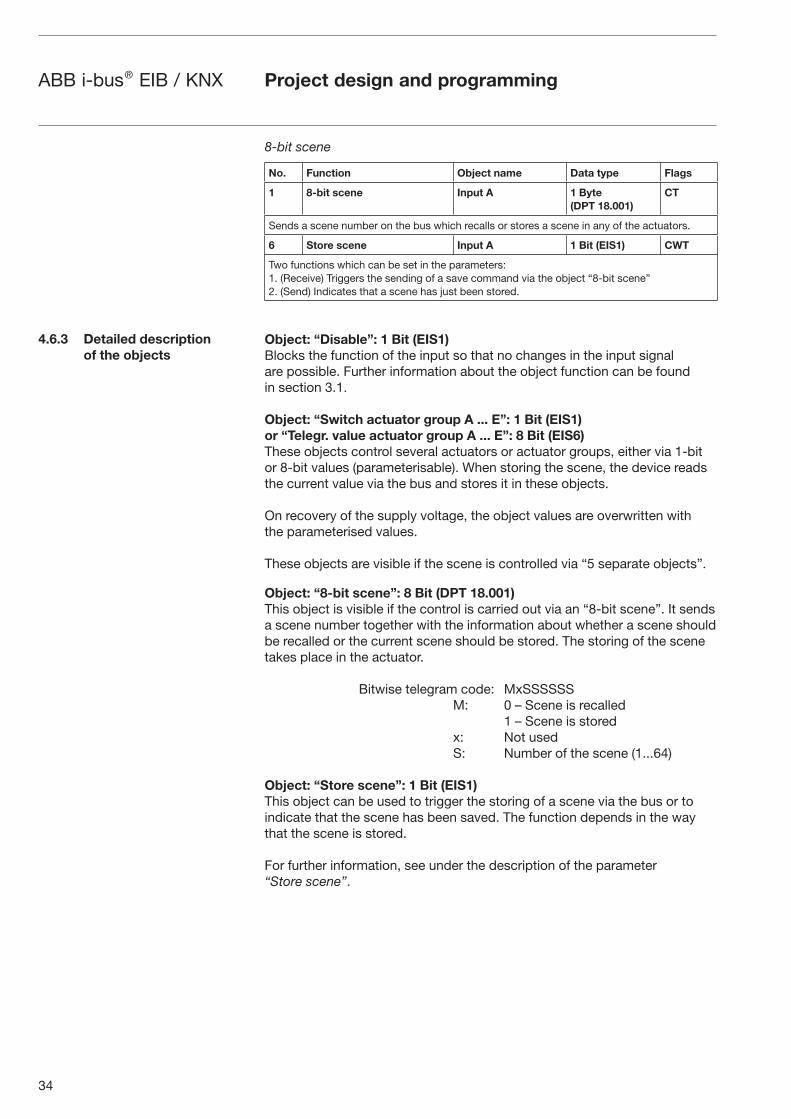
8-bit scene
No. Function Object name Data type Flags
1 8-bit scene Input A 1 Byte
(DPT 18.001)
CT
Sends a scene number on the bus which recalls or stores a scene in any of the actuators.
6 Store scene Input A 1 Bit (EIS1) CWT
Two functions which can be set in the parameters: 1. (Receive) Triggers the sending of a save command via the object “8-bit scene” 2. (Send) Indicates that a scene has just been stored.
Object: “Disable”: 1 Bit (EIS1)
Blocks the function of the input so that no changes in the input signal are possible. Further information about the object function can be found in section 3.1.
Object: “Switch actuator group A ... E”: 1 Bit (EIS1)
or “Telegr. value actuator group A ... E”: 8 Bit (EIS6)
These objects control several actuators or actuator groups, either via 1-bit or 8-bit values (parameterisable). When storing the scene, the device reads the current value via the bus and stores it in these objects.
On recovery of the supply voltage, the object values are overwritten with the parameterised values.
These objects are visible if the scene is controlled via “5 separate objects”.
Object: “8-bit scene”: 8 Bit (DPT 18.001)
This object is visible if the control is carried out via an “8-bit scene”. It sends a scene number together with the information about whether a scene should be recalled or the current scene should be stored. The storing of the scene takes place in the actuator.
Bitwise telegram code: MxSSSSSS M: 0 – Scene is recalled 1 – Scene is stored x: Not used S: Number of the scene (1...64)
Object: “Store scene”: 1 Bit (EIS1)
This object can be used to trigger the storing of a scene via the bus or to indicate that the scene has been saved. The function depends in the way that the scene is stored.
For further information, see under the description of the parameter “Store scene”.
35
ABB i-bus® EIB / KNX Project design and programming
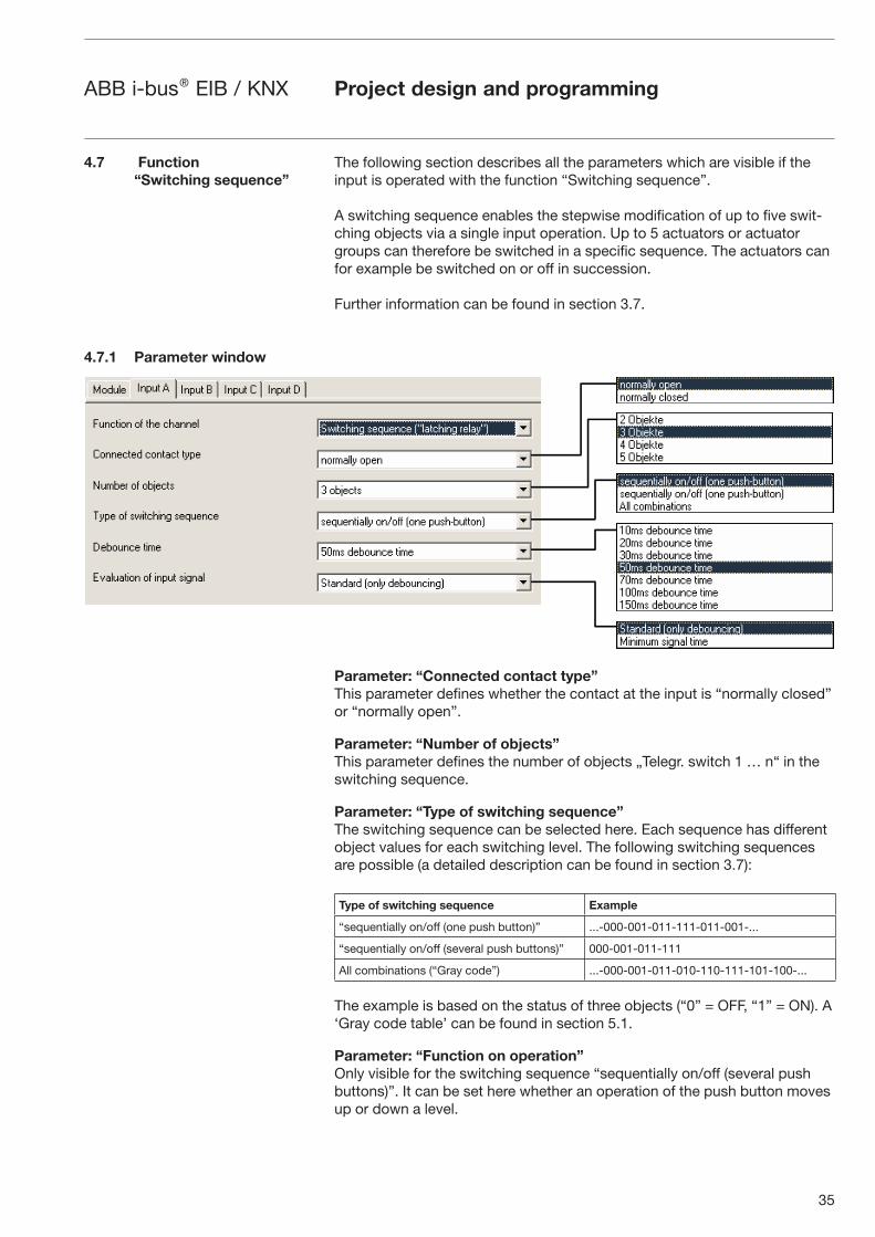
The following section describes all the parameters which are visible if the input is operated with the function “Switching sequence”.
A switching sequence enables the stepwise modification of up to five swit-ching objects via a single input operation. Up to 5 actuators or actuator groups can therefore be switched in a specific sequence. The actuators can for example be switched on or off in succession.
Further information can be found in section 3.7.
Parameter: “Connected contact type”
This parameter defines whether the contact at the input is “normally closed” or “normally open”.
Parameter: “Number of objects”
This parameter defines the number of objects „Telegr. switch 1 … n“ in the switching sequence.
Parameter: “Type of switching sequence”
The switching sequence can be selected here. Each sequence has different object values for each switching level. The following switching sequences are possible (a detailed description can be found in section 3.7):
Type of switching sequence Example
“sequentially on/off (one push button)” ...-000-001-011-111-011-001-...
“sequentially on/off (several push buttons)” 000-001-011-111
All combinations (“Gray code”) ...-000-001-011-010-110-111-101-100-...
The example is based on the status of three objects (“0” = OFF, “1” = ON). A ‘Gray code table’ can be found in section 5.1.
Parameter: “Function on operation”
Only visible for the switching sequence “sequentially on/off (several push buttons)”. It can be set here whether an operation of the push button moves up or down a level.
4.7 Function
“Switching sequence”
4.7.1 Parameter window
36
ABB i-bus® EIB / KNX
Parameter: “Debounce time”
Debouncing prevents unwanted multiple operation of the input e.g. due to bouncing of the contact. Refer to section 3.2 for the precise function of this parameter.
Parameter: “Evaluation of input signal”
Used for setting a minimum signal time.
After a pulse edge, the input waits for the minimum signal time. The change at the pulse edge is only valid if a further transition occurs during this period. If a further pulse edge occurs, the minimum signal time is restarted. The mini-mum signal time can be set separately for the rising and falling edge. Further information about the function can be found in section 3.2.
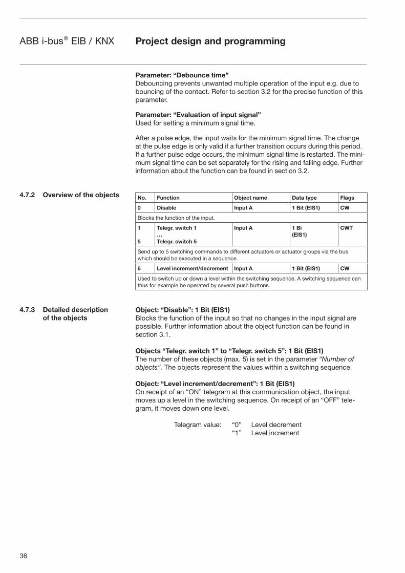
No. Function Object name Data type Flags
0 Disable Input A 1 Bit (EIS1) CW
Blocks the function of the input.
1
5
Telegr. switch 1
…
Telegr. switch 5
Input A 1 Bi
(EIS1)
CWT
Send up to 5 switching commands to different actuators or actuator groups via the bus which should be executed in a sequence.
6 Level increment/decrement Input A 1 Bit (EIS1) CW
Used to switch up or down a level within the switching sequence. A switching sequence can thus for example be operated by several push buttons.
Object: “Disable”: 1 Bit (EIS1)
Blocks the function of the input so that no changes in the input signal are possible. Further information about the object function can be found in section 3.1.
Objects “Telegr. switch 1” to “Telegr. switch 5”: 1 Bit (EIS1)
The number of these objects (max. 5) is set in the parameter “Number of objects”. The objects represent the values within a switching sequence.
Object: “Level increment/decrement”: 1 Bit (EIS1)
On receipt of an “ON” telegram at this communication object, the input moves up a level in the switching sequence. On receipt of an “OFF” tele-gram, it moves down one level.
Telegram value: “0” Level decrement “1” Level increment
Project design and programming
4.7.2 Overview of the objects
4.7.3 Detailed description
of the objects

37
ABB i-bus® EIB / KNX Project design and programming
4.8 Function: “Push button
with multiple operation”
4.8.1 Parameter window
The following section describes all the parameters and objects which are visible if the input is operated with the function “Push button with multiple operation”.
If the input is operated many times in succession, a specific object value can be modified depending on the number of operations. Different lightscenes for example are thus enabled by a multiple push button action.
Parameter: “Connected contact type”
This parameter defines whether the contact at the input is “normally closed” or “normally open”.
Parameter: “Max. number of operations”
This parameter specifies the maximum number of operations that are possible. This number is identical to the number of communication objects “Telegr. operation x-fold”. If the actual number of operations is greater than the maximum value set here, the input reacts as if the number of operations were identical to the selected maximum value.
Parameter: “Transmitted value”
It can be set here which object value should be sent. The settings “ON”, “OFF” and “TOGGLE” are possible. If “TOGGLE” is selected, the current object value is inverted.
Parameter: “Transmit value on every operation”
In the case of a multiple operation, if this parameter is set to “yes”, the associated object value is updated and sent after each operation. The following examples clarify this:

38
ABB i-bus® EIB / KNX
Transmit value at every operation = no
Transmit value at every operation = yes
Parameter: “Maximum time between two operations”
The period Tmax which defines how much time can elapse between two ope-rations is set here. After an operation, there is a delay for the time specified here. If there are no further operations within this period, the object “Telegr. switch” is sent and counting starts again with the next operation.
Parameter: “Additional object for long operation”
After a long operation of the input, it is possible for a further function to be executed via the object “Telegr. switch (long)”. If a long operation is carried out after one or several short operations within the maximum period, the short operations are ignored.
Parameter: “Long operation after”
This parameter defines the period from which an operation is interpreted as “long”.
Parameter: “Transmitted value”
It can be set here whether the object value “Telegr. switch –long” should be switched “ON”, “OFF” or toggled after a long operation.
Parameter: “Evaluation of input signal”
Used for setting a minimum signal time.
After a pulse edge, the input waits for the minimum signal time. The change at the pulse edge is only valid if a further edge occurs during this period. If a further pulse edge occurs, the minimum signal time is restarted. The minimum signal time can be set separately for the rising and falling edge. Further information about the function can be found in section 3.2.
The parameter is visible if there is no distinction between a short and long operation.
Parameter: “Debounce time”
Debouncing prevents unwanted multiple operation of the input e.g. due to bouncing of the contact. Refer to section 3.2 for the precise function of this parameter.
Project design and programming
Transmittedobject
Input signal
1-foldoperation
2-foldoperation
3-foldoperation
Transmittedobject
Input signal
3-foldoperation

39
ABB i-bus® EIB / KNX
No. Function Object name Data type Flags
0 Disable Input A 1 Bit (EIS1) CW
Blocks the function of the input.
1
4
Telegr. operation 1-fold
…
Telegr. operation 4-fold
Input A 1 Bit (EIS1) CWT
Send a switching command after a multiple operation.
5 Telegr. operation long Input A 1 Bit (EIS1) CWT
Sends a switching command after a long operation.
Object: “Disable”: 1 Bit (EIS1)
Blocks the function of the input so that no changes in the input signal are possible. Further information about the object function can be found in section 3.1.
Objects: “Telegr. operation 1..4-fold”: 1 Bit (EIS1)
The number of these objects (max. 4) is set in the parameter “Max. number of operations”.
After a multiple operation of an input, the corresponding object is sent according to the number of operations. The telegram value can be set in the parameters.
Object: “Telegr. operation long”: 1 Bit (EIS1)
This object is visible if the value “yes” has been set in the parameter “Additional object for long operation”.
This object is sent once a long operation has been detected. The telegram value can be set in the parameters.
Project design and programming
4.8.2 Overview of the objects
4.8.3 Detailed description
of the objects
40
ABB i-bus® EIB / KNX Project design and programming
4.9 Function: “Counter”
4.9.1 Parameter window
The following section describes all the parameters and objects which are visible if the input is operated with the “Counter” function.
With the “Counter” function, the device is able to count the number of pulse edges at the input. In addition to the normal “Counter”, a “Differential coun-ter” is made available if required. Both counters are controlled in the same way via the counting pulses but count independently of each other. The differential counter always has the same data width as the counter.
Further information and important notes can be found in section 3.8.
Parameter: “Pulse detection on”
The type of the input signal is defined in this parameter. It can set whether the contact is a “closing contact (rising edge)” or an “opening contact (falling edge)”.
Parameter: “Data width of counter”
The data width of the counter is defined in this parameter. It specifies the counting range that can be used. The data width is identical for the counter and the differential counter.
Parameter “Counter starts at …”
The starting value of the absolute counter is defined in this parameter. The starting value is used when the counter overruns in order to calculate the new counter value.
Parameter: “Enable additional options (...)”
If this parameter is set to “yes”, the parameter window “A: Counter” becomes visible. Additional functions are possible here.
Parameter: “Debounce time”
Debouncing prevents unwanted multiple operation of the input e.g. due to bouncing of the contact. Refer to section 3.2 for the precise function of this parameter.
41
ABB i-bus® EIB / KNX
Parameter: “Transmit counter values after bus voltage recovery”
If this parameter is set to “yes”, the current value of the counter is sent on the bus after bus voltage recovery (once the transmission delay has elapsed). If the differential counter has been enabled, it is also sent on the bus.
After a lengthy bus voltage failure, the counter is reset to the starting value. If the differential counter is enabled, it is reset to zero. If no data loss has occurred after a short bus voltage failure, the counter contents are retained.
Additional functions for the counter are enabled in this parameter window.
Parameter: “Divider: Number of input pulses for one counter step”
It can be set via this parameter how many input pulses (edges) are necessary for a counting pulse to be generated. It thus acts as a divider and subsequent decimal places are truncated.
Parameter: “Factor: One counter changes counter value by”
It can be set via this parameter by how much the counter and differential counter are increased for a counting pulse. It thus acts as a factor.
Parameter: “Transmit counter values cyclically”
If this parameter is set to “yes”, the values of the counter and the differential counter are sent cyclically on the bus.
Parameter: “Counter values are being transmitted every”
This parameter is visible if the parameter “Transmit counter values cyclically” is set to “yes”. It can be defined in which intervals the values are sent cycli-cally on the bus.
Parameter “Enable differential counter”
The object “Differential counter” is made visible via this parameter. The differential counter can adopt e.g. the function of a daily counter.
Project design and programming
Additional parameter window for “Enable additional options (...)” = “yes”:
42
ABB i-bus® EIB / KNX
Parameter: “Overrun/underrun of differential counter at”
This parameter is visible if the parameter “Enable differential counter” is set to “yes”.
It can be set in this parameter at which value the differential counter gene-rates an overrun. In the case of an overrun, the same rules apply as for the standard counter. The object “Differential counter overflow” is sent following an overrun.
Example: Factor 10 has been set in the parameters. If the overrun value is 47, the following counting sequence is produced: 10 – 20 – 30 – 40 – 3 – 13 – 23 – ...
No. Function Object name Data type Flags
0 Disable Input A 1 Bit (EIS1) CW
Blocks the function of the input.
1 Telegr. counter value ... bytes Input A 1 ... 4 Byte CWT
Contains the counter value (absolute value).
2 Differential counter ... bytes Input A 1 ... 4 Byte CWT
Contains the status of the differential counter.
3 Request counter values Input A 1 Bit (EIS1) CW
Requests the object values “Telegr. counter value” and “Differential counter”.
4 Differential counter overflow Input A 1 Bit (EIS1) CW
Sends a “1” when there is an overrun of the differential counter.
5 Reset differential counter Input A 1 Bit (EIS1) CW
Resets the differential counter to the starting value.
Object: “Disable”: 1 Bit (EIS1)
Blocks the function of the input so that no changes in the input signal are possible. Further information about the object function can be found in section 3.1.
Object: “Telegr. counter value ... bytes”: 1 to 4 Byte
This object contains the absolute counter content of the counter. The counter can have a data width of 1 byte, 2 bytes and 4 bytes. The following table provides an overview of the data types:
Data width EIS type Value range
1 byte EIS 14 0...255
2 byte EIS 10 -32.768...32.767
2 byte EIS 10 0...65.535
4 byte EIS 11 -2.147.483.648...2.147.483.647
Project design and programming
4.9.2 Overview of the objects
4.9.3 Detailed description
of the objects
43
ABB i-bus® EIB / KNX Project design and programming
Object: “Differential counter ... bytes”: 1 to 4 Byte
This object is visible if the value “yes” has been selected in the parameter “Enable differential counter”.
The object contains the content of the differential counter which is identical to the absolute counter in its counting function. In contrast, it can be reset (object “Reset differential counter”) and a counter overrun can be reported on the bus (object “Differential counter overflow”). It is possible to measure e.g. daily consumption values via the differential counter.
As soon as the differential counter has reached, exceeded or fallen below the overrun value specified in the parameter “Overrun/underrun of differential counter at”, the overrun value is deducted from the value of the differential counter.
Object: “Request counter values”: 1 Bit (EIS1)
The values of the absolute counter and the differential counter are requested via this object.
Telegram value: “0” No reaction “1” Request counter values
Object: “Differential counter overflow”: 1 Bit (EIS1)
This object is visible if the value “yes” has been set in the parameter “Enable differential counter”.
As soon as the value of the differential counter has exceeded or fallen below the value defined in the parameter “Overrun/underrun of differential counter at“, the object is sent on the bus (telegram value = “1”).
Note: After an overrun, the object receives the value “1”. If the object value should be reset to “0” via the bus, the “Write” flag of the object should be set.
Object: “Reset differential counter”: 1 Bit (EIS1)
This object is visible if the value “yes” has been set in the parameter “Enable differential counter”. The differential counter can be reset to the value “0”.
Telegram value: “0” No reaction “1” Reset differential counter
44
ABB i-bus® EIB / KNX Appendix
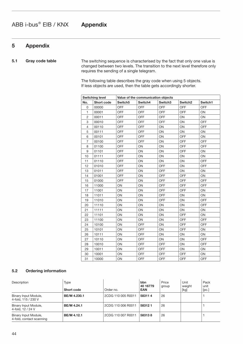
The switching sequence is characterised by the fact that only one value is changed between two levels. The transition to the next level therefore only requires the sending of a single telegram.
The following table describes the gray code when using 5 objects. If less objects are used, then the table gets accordingly shorter.
Switching level Value of the communication objects
No. Short code Switch5 Switch4 Switch3 Switch2 Switch1
0 00000 OFF OFF OFF OFF OFF
1 00001 OFF OFF OFF OFF ON
2 00011 OFF OFF OFF ON ON
3 00010 OFF OFF OFF ON OFF
4 00110 OFF OFF ON ON OFF
5 00111 OFF OFF ON ON ON
6 00101 OFF OFF ON OFF ON
7 00100 OFF OFF ON OFF OFF
8 01100 OFF ON ON OFF OFF
9 01101 OFF ON ON OFF ON
10 01111 OFF ON ON ON ON
11 01110 OFF ON ON ON OFF
12 01010 OFF ON OFF ON OFF
13 01011 OFF ON OFF ON ON
14 01001 OFF ON OFF OFF ON
15 01000 OFF ON OFF OFF OFF
16 11000 ON ON OFF OFF OFF
17 11001 ON ON OFF OFF ON
18 11011 ON ON OFF ON ON
19 11010 ON ON OFF ON OFF
20 11110 ON ON ON ON OFF
21 11111 ON ON ON ON ON
22 11101 ON ON ON OFF ON
23 11100 ON ON ON OFF OFF
24 10100 ON OFF ON OFF OFF
25 10101 ON OFF ON OFF ON
26 10111 ON OFF ON ON ON
27 10110 ON OFF ON ON OFF
28 10010 ON OFF OFF ON OFF
29 10011 ON OFF OFF ON ON
30 10001 ON OFF OFF OFF ON
31 10000 ON OFF OFF OFF OFF
5 Appendix
5.1 Gray code table
5.2 Ordering information
Description Type
Short code Order no.
bbn40 16779EAN
Pricegroup
Unitweight[kg]
Packunit[pc.]
Binary Input Module, 4-fold, 115 / 230 V
BE/M 4.230.1 2CDG 110 005 R0011 58311 4 26 1
Binary Input Module, 4-fold, 12 / 24 V
BE/M 4.24.1 2CDG 110 006 R0011 58312 1 26 1
Binary Input Module, 4-fold, contact scanning
BE/M 4.12.1 2CDG 110 007 R0011 58313 8 26 1

The information in this leaflet is subject to change without further notice. Pub
. No.
2C
DC
514
022
D02
01
Your EIB-Partner