product load mechanism - worcester polytechnic institute€¦ · product load mechanism ... a...
TRANSCRIPT

Project Number: GLPC-RLN-10-11
Product Load Mechanism
A Major Qualifying Project Report
submitted to the Faculty
of the
WORCESTER POLYTECHNIC INSTITUTE
in partial fulfillment of the requirements for the
Degree of Bachelor of Science
by
_______________ _______________ _______________ _______________
Megan Faulkner Laura Friedman Stephen Galucki John Moakley
Date: March 4, 2011
Approved:
________________________________
Professor Robert L. Norton, Advisor
________________________________
Professor Diana A. Lados, Advisor

1
Acknowledgements
The MQP team would like to thank the following people for their assistance and support
throughout the course of this project.
Professor Robert L. Norton
Professor Diana A. Lados
Charlie Gillis
Krystyna Gielo-Perczak
Neil Whitehouse
Jeff Gorges
Torbjorn Bergstrom
Washburn Shops Staff at WPI
Higgins Laboratories Staff at WPI

2
Abstract
The goal of this project was to design a better way of transporting an extruded foam
product from a reel to a load head on an assembly. The problem was broken into five parts:
splitting, indexing, cutting, merging and inserting. The splitting and cutting steps were already
solved by the sponsor, so the team created solutions for the remaining three processes. They
were solved in two subassemblies: a grabbing and indexing mechanism that provided movement
to the product on a track, and a shuttle mechanism that merged the two lines of product and
inserted them into the load head.

3
Executive Summary
The goal of this project was to design a better way of transporting an extruded foam
product from a reel to a load head on an assembly. The sponsor’s current method of moving the
product jams frequently causing large amounts of machine down-time.
Material Testing
Material testing was conducted to obtain the compressive and tensile forces that the
product could be subjected to. The product’s tensile properties were examined using an Instron
tensile testing machine, to determine ultimate tensile strength, Young’s Modulus, yield strength,
and breaking force. This data was then used in the design process.
Design
The product is initially on a reel as a two-sided foam extrusion. It must be pulled off the
reel and indexed through a splitter where the two sides of the foam extrusion will be split down
the middle into two product streams. Next it will be advanced to a cutting station where it will be
cut to length. The product is merged and inserted into the load jaws as two separate parts. The
primary goal of the project was to design the indexing, merging and loading mechanisms. The
sponsor indicated that the current de-reeler, splitter and cutter were satisfactory and did not need
to be re-designed. This left the indexing and grabbing and merging to be designed.
Indexing
The indexer needed to pull the product through the splitter and into the cutting station. To
accomplish this, we designed several different mechanisms before finalizing a design. The final
design uses a Festo toothed belt that is axially controlled by two servomotors to create the
indexing motion.

4
Grabbing
The product needed to be grabbed during the indexing process. The specifications
required that the product be grabbed in a way that would not damage it or allow slipping.
Different concepts were designed using mechanical and pneumatic grabbers. The final design
uses a Festo piston to control a plate that closes on the two streams of product when they are to
be indexed forward.
Merging
Both of the streams of cut product needed to be merged into one stream and placed in the
load jaw. After several iterations, one device was designed to satisfy both the merging and
loading needs. The shuttle mechanism designed uses solenoids to alternate a shuttle between the
two tracks of product. As a vacuum pulls a cut piece of the product into one side of the shuttle, it
uses a jet of air to push the previously acquired strip out of the shuttle and into the load jaw.
Final Overall Assembly
The final assembly, shown in Figure 1, maintains full control of the product during the
entire process. A track was created to guide the product between stations, and mounting brackets

5
were designed to join all of the stations to the existing assembly line and each other.
Figure 1: Final Assembly

6
Table of Contents
Acknowledgements ......................................................................................................................... 1
Abstract ........................................................................................................................................... 2
Executive Summary ........................................................................................................................ 3
Material Testing .......................................................................................................................... 3
Design ......................................................................................................................................... 3
Indexing ...................................................................................................................................... 3
Grabbing ..................................................................................................................................... 4
Merging ....................................................................................................................................... 4
Final Overall Assembly .............................................................................................................. 4
List of Figures ................................................................................................................................. 8
List of Tables ................................................................................................................................ 11
Introduction ................................................................................................................................... 12
1. Background Research ............................................................................................................... 16
1.1 Indexing .............................................................................................................................. 16
1.2 Grabbing ............................................................................................................................. 19
1.3 Merging ............................................................................................................................... 21
1.4 Material Properties .............................................................................................................. 24
2. Preliminary Analysis ................................................................................................................. 26
2.1 Sponsor Feedback ............................................................................................................... 26

7
2.2 System Analysis Using CAD .............................................................................................. 27
2.3 Material Testing .................................................................................................................. 29
2.3.1 Introduction .................................................................................................................. 29
2.3.2 Methodology ................................................................................................................ 30
2.3.3 Results .......................................................................................................................... 31
3. Design ....................................................................................................................................... 34
3.1 Indexing Design .................................................................................................................. 34
3.1.1 Early Design Iterations ................................................................................................ 34
3.1.2 Linear Slide .................................................................................................................. 37
3.2 Grabbing Design ................................................................................................................. 40
3.2.1 Spring Gripper ............................................................................................................. 40
3.2.2 Hug Feeder ................................................................................................................... 41
3.2.3 Mechanical Grabber ..................................................................................................... 42
3.2.4 Piston Grabber ............................................................................................................. 47
3.2.5 Final Grabbing Design ................................................................................................. 51
3.2.6 Piston Prototyping and Testing .................................................................................... 59
3.3 Shuttle and Track Development.......................................................................................... 65
3.3.1 Air-Jet Injection ........................................................................................................... 65
3.3.2 Tommy Gun Concept ................................................................................................... 67
4. Results ....................................................................................................................................... 82

8
5. Conclusions and Recommendations ......................................................................................... 84
Appendix A: Indexing and Grabbing Mechanism Drawings ....................................................... 85
Appendix B: Merging Mechanism Drawings ............................................................................... 91
Appendix C: Track and Mounting Drawings ................................................................................ 98
Appendix D: Product Testing Results......................................................................................... 111
Appendix E: Product Data Sheets ............................................................................................... 117
7. Bibliography ........................................................................................................................... 120
List of Figures
Figure 1: Final Assembly ................................................................................................................ 5
Figure 2: Block Diagram of Full Design ...................................................................................... 14
Figure 3: Timing Belt.................................................................................................................... 16
Figure 4: Parallel Shaft Drive and Index Machine ....................................................................... 17
Figure 5: Geneva Mechanism ....................................................................................................... 18
Figure 6: Slider Crank Mechanism ............................................................................................... 18
Figure 7: Festo Toothed Belt Axes Drive ..................................................................................... 19
Figure 8: Gripper Mechanism ....................................................................................................... 20
Figure 9: Piston-Cylinder Schematic ............................................................................................ 21
Figure 10: Lane Merger Apparatus ............................................................................................... 23
Figure 11: Apparatus for Combining Articles from Plural Lanes into a Single Lane .................. 24
Figure 12: Complied Data Stress-Strain Curve ............................................................................ 31
Figure 13: Stress-Strain Curve Compiled Data ............................................................................ 32

9
Figure 14: The Initial Design of the Eccentric Crank ................................................................... 35
Figure 15: The Rotated Eccentric Crank ...................................................................................... 36
Figure 16: Indexer-Grabber Assembly ......................................................................................... 37
Figure 17: Complete Indexing Assembly ..................................................................................... 38
Figure 18: The Velocity Profile of the Servo Motor..................................................................... 39
Figure 19: The Custom Motor Brackets ....................................................................................... 40
Figure 20: Spring Gripper ............................................................................................................. 41
Figure 21: Hug Feeder .................................................................................................................. 42
Figure 22: Mechanical Grabber .................................................................................................... 43
Figure 23: Updated Mechanical Grabber ...................................................................................... 44
Figure 24: Back of Updated Mechanical Grabber ........................................................................ 45
Figure 25: Tab ............................................................................................................................... 46
Figure 26: Piston Grabber ............................................................................................................. 47
Figure 27: Piston Grabber on Linear Guide .................................................................................. 49
Figure 28: Smaller Piston Assembly............................................................................................. 50
Figure 29: Final Piston Grabbing Design ..................................................................................... 51
Figure 30: Piston Assembly .......................................................................................................... 52
Figure 31: Back View of Piston Housing Mounting .................................................................... 53
Figure 32: Piston Support ............................................................................................................. 54
Figure 33: Piston Block in Closed and Open Position .................................................................. 55
Figure 34: Side (left) and head on (right) view of plate mounting ............................................... 56
Figure 35: Base ............................................................................................................................. 57
Figure 36: Front View of Mounting Base ..................................................................................... 58

10
Figure 37: Overall Piston Assembly with Linear Slide ................................................................ 59
Figure 38: CAD Prototype and Physical Model ........................................................................... 60
Figure 39: Piston Grabber Test Rig .............................................................................................. 62
Figure 40: Loaded Piston Grabber ................................................................................................ 63
Figure 41: Air-jet Injection Concept ............................................................................................. 66
Figure 42: Tommy Gun Concept .................................................................................................. 67
Figure 43: Shuttle Assembly Top View ....................................................................................... 69
Figure 44: Ledex Solenoid Force and Speed Vs. Stroke Charts ................................................... 70
Figure 45: Solenoid Test Assembly .............................................................................................. 73
Figure 46: Acceleration of Test Shuttle Mass............................................................................... 74
Figure 47: Alternate Shuttle Track Iteration ................................................................................. 76
Figure 48: Model of Alternate Track Design ................................................................................ 77
Figure 49: Alternate Track Design Manufactured Parts ............................................................... 77
Figure 50: Track Profile (dimensions are in mm) ......................................................................... 78
Figure 51: Top Section of Track in Open Position ....................................................................... 80
Figure 52: Top Section of Track in Closed Position..................................................................... 80
Figure 53: Overall Assembly ........................................................................................................ 82
Figure 54: Sample 2-Load versus Time ...................................................................................... 111
Figure 55: Sample 3-Load versus Time ...................................................................................... 111
Figure 56: Sample 4-Load versus Time ...................................................................................... 111
Figure 57: Sample 5-Load versus Time ...................................................................................... 112
Figure 58: Sample 6-Load versus Time ...................................................................................... 112
Figure 59: Sample 7-Load versus Time ...................................................................................... 112

11
Figure 60: Sample 8-Load versus Time ...................................................................................... 113
Figure 61: Sample 2-Load versus Extension .............................................................................. 113
Figure 62: Sample 3-Load versus Extension .............................................................................. 114
Figure 63: Sample 4-Load versus Extension .............................................................................. 114
Figure 64: Sample 5-Load versus Extension .............................................................................. 115
Figure 65: Sample 6-Load versus Extension .............................................................................. 115
Figure 66: Sample 7-Load versus Extension .............................................................................. 116
Figure 67: Sample 8-Load versus Extension .............................................................................. 116
Figure 68: VXB Linear Bearings Specifications ........................................................................ 117
Figure 69: Ledex Solenoid Specifications .................................................................................. 119
List of Tables
Table 1: Material Properties.......................................................................................................... 33
Table 2: Rubber Testing Results ................................................................................................... 65
Table 3: Lee Spring's Wave Spring Specifications ..................................................................... 117
Table 4: Ledex Solenoid Duty Cycle .......................................................................................... 118

12
Introduction
Manufacturing large quantities of parts requires efficient, automated machines. These
automated assembly machines are responsible for creating products for today’s consumers. The
desired effects of these procedures are minimizing production costs, increasing the speed of
assembly, and maximizing the quality of the product.
Our sponsor company presents us with the challenge of designing a machine to handle a
material that is inserted into several of their products. The raw material is a foam extrusion
which needs to be pulled off a reel, split in half, cut to length, and inserted into the product. The
material must be grabbed, indexed, cut to the proper length, and have the two split lines of
material merged onto one line.
The material is brittle and is easily deformed under minimal pressure. One task is to
create a grabbing device that does not change the profile of the extrusion or damage it. Grabbing
the material can be done in different ways, such as mechanically driven devices or pneumatics.
The desired goal is to grab the material with the minimum forced to pull it while retaining its
original shape.
Indexing devices are used in a wide variety of applications to move stock in increments.
Their purpose is to move the stock in the assembly line by a specified amount. There are many
devices used to achieve indexing, such as four-bar mechanisms, gears, cam and follower
systems, linear slides, and rotary devices. The purpose of the indexer in this project is to
simultaneously work with the grabber device to pull the product from its reel and move it to the
cutting station. Our task is to find the simplest mode of indexing the raw stock. The cutting
station is simply a blade that shears the product to the proper length. The sponsor provided the
cutting device to the group, as there was no need for redesign.

13
The two separate lines of product produced from the splitting function must be merged
into a single line. This requires a merging process for the product. Additionally, the two lines of
product must be constrained within a track to guide them through the processes. This requires a
custom track design fit to the product.
The problem as presented by the sponsor was to create a new method of moving a
product from a reel on which it is stored upon to a load head on an assembly line. In order to
accomplish this, the problem was divided into several parts. The product itself is a foam
extrusion which, after it is manufactured, is stored on a large reel. The profile that is
manufactured must be split in two and cut to length before it is ready to be inserted into the load
head. The splitting of the product results in two lines that must be joined and inserted into the
same load head. This requires a merging step that also had to be completed. Finally, in order to
transport the product between these steps, an indexing process also had to be introduced. The
order of these steps would determine the design of our assembly and therefore had to be
determined before the design process began.
There was a balance between several of the steps that had to be considered to optimize
the order of sub-assemblies in the overall assembly. The indexing mechanism must be able to
pull the slack of the product off the reel and push it forward from there. In order to be able to pull
the product, this step had to occur before the cutting. However, the cut product may still be
indexed using the same device if the products push each other end to end. Therefore, the cutting
assembly is placed after the indexing mechanism.
The indexing and merging steps also had to be balanced to create a working assembly. If
the two lines resulting from the splitting are joined into the same line, the resulting line will
move at twice the pace of the dual lines. Although the merging step has to occur after the

14
indexing and cutting steps, this is an advantage that permits twice as much time for the indexing,
splitting, and cutting steps as the assembly line indexes. To merge the two lines, however, the
singular line must alternate accepting the product between the dual lines. A mechanism must be
created to fulfill this requirement.
An order of functions was decided upon considering these aspects. First, the indexing
mechanism unreels and pulls the product through the splitting process. According to the sponsor,
the current splitting mechanism is adequate and does not need to be redesigned. Next, a slicing
machine cuts the product to length. This slicer, as with the splitter, does not need a redesign and
is provided by the sponsor. Finally, the products will be merged and inserted into the load head.
Figure 2 shows a block diagram of the overall design.
Figure 2: Block Diagram of Full Design

15
To achieve this, initial background research and analysis were done. We researched
machines with similar functions in order to create several iterations before achieving a final
design. We were sent a CAD model of the load head mechanism that our design would interface
with. We reverse engineered the model to understand its functionality. Material testing and
analysis was also done to observe how the material behaves and to obtain values for analytical
calculations.

16
1. Background Research
1.1 Indexing
A facet of the necessary background research was to investigate existing indexing
machines and see if there was one suitable for the task at hand.
One of the first areas investigated was that of indexing belt drives. A belt can carry cut
pieces of the product between the cutter and the load mechanism. To precisely control the
product throughout the entire process, timing belt or chain systems could be used. A timing belt
(shown in Figure 3) is a belt with a toothed inside edge which allows for precise positioning. A
timing chain is a series of links that has gearing notches on its underside to allow for precise
control of its positioning in the same fashion as a timing belt. Problems found with timing belts
or chains were that the product would need to be tightly controlled and contained while on it,
which could be difficult considering the amount of vibration that may be found on a timing belt
or chain during operation. The level of complexity required in creating a custom timing chain or
belt was also outside of the scope of this project.
Figure 3: Timing Belt
Investigating existing patents was an important part of this project. There are many
different types of indexing motions available, and it was important to see if an existing one could

17
be modified to suit our needs. The device of Figure 4 is patent number 5176036 titled “Parallel
Shaft Drive and Index Machine” created by William O. Harris, and uses a cam to index a rotary
drive. This could work if an appropriate clamping motion on the product could be found. The
main problem is that it only moves in one direction and it would be difficult to get a uniform
clamping force to stay on the product for the total distance that it needs to move.
Figure 4: Parallel Shaft Drive and Index Machine
Another option for indexing is the “Geneva Mechanism”. This term encapsulates a
variety of designs, with the basic concept shown in Figure 5. This concept allows for intermittent
rotation in one direction, but has the cons of being a purely mechanical device and therefore
being subject to wear, as well as causing excessive noise due to the mechanical interactions of
the parts.

18
Figure 5: Geneva Mechanism
A more suitable candidate to complete the motion would be a slider crank mechanism. A
disk rotates around its central axis, with a link near its outer diameter. The outer link can be used
as a precision driver, such as in Figure 6. Coupled with a servo motor this is a precise and
powerful tool, and is investigated further in the report.
Figure 6: Slider Crank Mechanism

19
There are commercially available products designed for the purpose of indexing. These
come in a variety of forms, and are driven by motors, servo motors or pneumatics. A servo
driven option was available through the automation manufacturer, Festo. Shown in Figure 7, it
incorporates a timing belt, except that many of the negatives associated with such a system had
been resolved. The belt of this product is internal, and is driven by two servo motors in order to
eliminate vibrations in the belt. On the top side of the belt is a guide that could be used to mount
an assembly on top. This type of system could position the top guide with repeatable precision.
Figure 7: Festo Toothed Belt Axes Drive
A similar type of system was also available from Festo, except instead of using a timing
belt for positioning, a ball screw was used to provide positioning of the guide rail. These systems
offered a more precise ability to locate the guide, but lacked the speed that would be necessary
for our operation.
1.2 Grabbing
One of the design specifications is to grab the product and pull it with enough force to
move through the machine without damaging it. Two concepts we researched were mechanical

20
and pneumatic grabbers. The mechanical grabbers consisted of jaws operated by a mechanical
device, such as an eccentric driver, a cam, or a linear actuator. An example of a mechanical
grabbing mechanism is displayed in Figure 8.
Figure 8: Gripper Mechanism
Figure 8 shows the patent entitled “Gripper Mechanism” by Geoffrey G. Shackleford, patent
number 4243257. This grabbing device consists of mechanical jaws operated by a linear
actuator. The jaws contain two links connected at their centers and a pin with grips attached to
the end of each link. The actuator is connected to link 3 in Figure 8, which opens and closes the
grips.
Pneumatic pistons were also researched as a mode of grabbing the product. Instead of
pinching the material between the jaws, the piston would descend onto the product with the
grippers completely parallel to its top and bottom surfaces. A pressure regulator controls the
pressure of air in the piston, which controls the force exerted by the piston onto the product. The
product would sit in a track below the piston. Therefore, the product could precisely and
accurately be gripped and indexed to its proper location. A piston-cylinder configuration is
shown in Figure 9 below.

21
Figure 9: Piston-Cylinder Schematic
In Figure 9, the piston is the “T” shaped part resting inside the cylinder. From the diagram it is
clear that force is exerted onto the piston from the gauge pressure, which is higher than the
atmospheric pressure, causing the piston to actuate.
1.3 Merging
A process that must be completed by our design is the combination of the two lines of
product resulting from the slicer. At the commencement of this project, the sponsor informed us
that their aim was for us to create a novel solution for the processes. Therefore, it was
determined that research would not be done into the systems that the sponsor is currently using
or has used in the past. It was believed that the influence of knowing previous setups would bias
our design towards a similar solution. Therefore, we researched patents not related to our
sponsor.
Several thoughts were kept in mind when completing research into patents. As stated by
our sponsor, we were looking for the simplest solution to the problem of merging, using the
fewest parts and least motion possible. Our investigation was conducted using Google Patents as

22
the search engine, as opposed to the United States Patent Office, due to a much more manageable
website and patent viewer.
A patent found regarding merging technology was Ted Haan’s “High Volume Conveyor
Sortation System”, US Patent Number 7128197. Although the products being moved within the
patent and the path lines were very different to ours, a couple of important points were made in
the text of the patent. Mr. Haan explained that the two most critical parts of merging multiple
product lines was timing the line offsets and maintaining the orientation of the two lines entering
the resulting line. The importance of these two actions was kept in mind during the design of the
merging mechanism.
John Cragun’s “Lane Merger Apparatus” was found to be more similar in shape to our
product lines. A picture of Mr. Cragun’s patent can be seen in Figure 10. The concept of his
patent is that three lines of product are shot into a single resulting line using belts on top of a
conveyor belt. The largest difference between the merging system that we must use and this
patent is that our product could not be joined using angles due to its length. When this was
realized, we determined that the tracks entering the merging process must be parallel and
maintain this orientation as to not deform the product. In addition to this, Mr. Cragun’s patent
uses belts to feed the product into the merging station, which we determined would not be the
best way to handle the product.

23
Figure 10: Lane Merger Apparatus
An alternative to having parallel tracks entering the merging station was introduced by
US Patent #4265356, Charles Glover’s “Apparatus for Combining Articles from Plural Lanes
into a Single Lane”. An image from the patent can be seen in Figure 11. Mr. Glover’s
mechanism has four lines of product that enter from the left and are held in their tracks by a plate
broken only by the resultant track. The resultant track pivots back and forth and accepts
individual products from each of the lines as they align. As long as the track that accepts the
product is lined up with the product, the tracks don’t have to be parallel entering the merging
station. There is still a flaw in this design, however. There is only one point in the rotation of the
track that allows for the product to leave the track. Therefore, even though the rotating part of
this assembly could accept both of the lines of product during one swing, it could only output
one of the products into the resulting line per swing.

24
Figure 11: Apparatus for Combining Articles from Plural Lanes into a Single Lane
During the design process, we searched to see if there was a patent similar to our concept
of a shuttle driven by solenoids. Using search terms such as shuttle, merging, product lines, and
solenoids, we did not find a patent with a similar design.
1.4 Material Properties
This project required material testing and analysis in addition to machine design. The
product being tested was brittle and weak but needed to be fed through a machine in a way that
would not damage it. Research on the material properties of the product was done, but there were
no available resources to satisfy our needs. The material properties needed were ultimate tensile
strength, breaking force, yield strength, and Young’s Modulus.
The ultimate tensile strength and breaking force needed to be found because the product
would be pulled along its longitudinal axis. Ultimate tensile strength is the maximum stress of
the material before it fractures, and the breaking force is the force at which the material breaks

25
while being pulled along its longitudinal axis. Ultimate tensile strength is measured in force per
unit area while breaking force is simply measured in force.
The yield strength would also need to be found to know at what stress the material would
deform. Yield strength is the stress at which the material can no longer return to its original
cross-section and shape. Once a material yields, it has plastically deformed. Brittle materials
have a very small, and sometimes nonexistent, elastic region on their stress-strain curves. It was
our prediction that the product would display this brittle behavior.
Young’s Modulus was also a significant material property to test for. This was because it
was important to understand how stiff the material was and how it would behave during axial
loading. On a stress-strain curve, Young’s Modulus is the slope of the linear region of the curve.
To find these properties, test rigs and samples needed to be made. A tensile tester
(Instron) was available to us through the Biomedical Engineering Department at WPI. The jaws
of the Instron could not grab the raw material without crushing it. Therefore, we needed to
successfully grip the material so that it could be pulled in the Instron. We experimented with
different types of grips and adhesives to attach to the ends of our test specimens. After several
trials, wooden dowels with an epoxy adhesive worked the best. All of the necessary material
properties were able to be found using the Instron machine. The results of these experiments are
described in detail in Section 2.3.

26
2. Preliminary Analysis
2.1 Sponsor Feedback
In our initial meeting with the sponsor company, we were able to tour their
manufacturing plant as well as meet with the engineers and liaisons. We were given descriptions
of all the available projects and had a questions and answer session. The sponsor explained
which projects were more design oriented and which were more analysis focused. From there,
the group chose a project from the list and began research and the design process.
During the course of our design process, we had biweekly design reviews with a liaison
who worked for the sponsor company. In these design reviews we discussed what work had been
completed since the last meeting, such as design changes, improvements, and test results. The
liaison provided feedback to help improve what we had already accomplished. Some major
topics during the design reviews were our progress on the project and if we were on track,
presenting different concepts for each machine station, reviewing our calculations for different
parameters of the design, and analyzing the material testing data.
Our liaison also guided us to the most efficient method of machine design. He sent us a
step by step guide on how to dissect our concepts and turn them into functioning designs. He also
aided us by giving advice on how to analyze and interpret the data we collected to improve our
designs.
The sponsor company and our advisor also helped us in finding suppliers to buy parts
from for our prototype. They also sent us hardware and parts of their own that we were able to
use.

27
2.2 System Analysis Using CAD
In order to better understand the mechanism that must be designed, a 3D model of the
infrastructure at the output of our design was created. CAD (Computer aided design) models of
the load mechanism were provided by our sponsor in Parasolid format, and imported into Solid
Works. However, Parasolids provide no intelligent features and it is not possible to edit or move
the resulting parts in assemblies. It was decided that a full, moving, assembly would be of the
best use to us, so the Parasolids were converted into Solid Works native files. The feature
recognition algorithm in Solid Works created feature trees for each part, with a few exceptions
which we manually fixed.
Unfortunately, the created assemblies’ components were all grounded to one another and
had no dynamic constraints, so the newly created native parts were put together in a new
assembly file. This was accomplished by dividing the overall assembly into sub-assemblies that
each team member created. This new assembly only used constraints that would be in the
tangible assembly, so the CAD assembly moved just as it does in the factory. The complete
model cannot be shown due to proprietary reasons, but the mechanism worked and showed us
the scope of the project. Several parameters were defined using this method. One of the primary
reasons for building the CAD model was ensuring that the mechanism we created would not
interfere with the motion of the nestings on the assembly line. Therefore, after our CAD
assembly was completed, it would be inserted into the overall assembly of the existing
infrastructure, using two mounting planes provided by our sponsor as references.
The mounting planes are another point that had to be incorporated into the design. The
current system uses dowel pins for positioning and tapped holes and screws for securing.
Grounding the assembly that we have created is important to ensure that there were no vibrations

28
or stresses that would result in performance drops of the system. Therefore, keeping in mind
mounting will be another important aspect of designing our assembly.

29
2.3 Material Testing
2.3.1 Introduction
Material properties of the product were found to use in the calculations for our design.
Four material properties were found using the Instron: Sut (ultimate tensile strength), Young’s
Modulus, yield strength, and the breaking force. The Sut is the maximum stress the material can
withstand before it fractures, or the maximum load sustained by the specimen during the tensile
test. Sut is important because it’s used in calculating the correct pressure needed for the grabbing
mechanism in this design. The yield strength is the stress at which the material is plastically
deformed, or the point at which the specimen experiences permanent damage (Keyser). Yield
strength is important to this design project for the same reason that Sut is. Additionally, the
sponsor company requested this material property for their records. The Young’s modulus
describes the stiffness of the material or shows the elastic resistance of the material to strain
(Keyser). It is important to understand how stiff the product is when designing a machine to pull
and push it. The breaking force is the force at which the material breaks when being pulled. The
product needed to be indexed through the machine, which meant that it would be pulled along its
longitudinal axis, making the breaking force an important parameter in our calculations. These
material properties were found in order to help us design a machine that did not damage the
product while it was being fed and for the benefit of the sponsor company.
The results of the material testing were calculated based upon engineering stress and
strain, not true stress and strain. Engineering stress does not consider the changing cross-section
of the test specimen. Engineering stress is the applied force divided by the original cross-section
of the material. True stress is the force applied divided by the instantaneous cross-sectional area

30
at a given time. Engineering stress and strain were used in this test because of its practicality in
this application.
2.3.2 Methodology
The product had to be secured in the Instron with grips. These grips were manufactured
from 3/8” wooden dowels with 3/32” x 1/2” holes drilled through their centers on a lathe. The
product was fastened in the dowels with a 2-part epoxy. The samples were set up on the Instron
with the following parameters: A rate of 8.896 N/min with end conditions at 0.03 m or 88.96 N.
These numbers were selected based on the initial hands-on testing. From experimentally pulling
the material with our fingers, it was concluded that the product would break well before 20
pounds of force, which is approximately 88.96 N. The rate was chosen arbitrarily to be 2 lbf/min,
which is 8.896 N/min. The Instron collected elongation data and force data from which stress-
strain curves were generated. Figure 12 shows the average stress-strain curve for all 8 samples
tested.

31
2.3.3 Results
Figure 12: Complied Data Stress-Strain Curve
A cubic function with an R2 value of 0.9964 was fit to the data. Its formula is:
( ) (1)
The ultimate tensile strength was found by deriving equation 1 and obtaining its roots. The roots
of the derivative of equation 1 will give the values of strain at which the stresses are maximum.
The derivative will have two roots as it is a quadratic equation. The derivative of equation 1 is:
( ) (2)
The roots of this function are (-0.03, 0.018). Evaluating equation 1 at the positive strain of 0.018
gave a y-value of 8.84 MPa, which was the ultimate tensile strength.
The yield strength and Young’s modulus were found by generating a line parallel to the
origin of the stress-strain curve and offsetting it by .2%. The slope of this curve was the Young’s
y = -511566x3 - 9203.1x2 + 824.38x
R² = 0.9964
0
1
2
3
4
5
6
7
8
9
0 0.002 0.004 0.006 0.008 0.01 0.012 0.014 0.016 0.018 0.02
Str
ess
(MP
a)
Strain
Average Stress-Strain Curve of 8 Samples

32
modulus and the point of intersection with the average stress-strain curve was the yield strength.
The equation for this offset line is shown in equation 3 below.
( ) ( ) (3)
The stress-strain curve, the 0.2% offset line, the ultimate tensile strength and yield strength are
plotted in Figure 13 .
Figure 13: Stress-Strain Curve Compiled Data
The tabulated data is shown in Table 1.

33
Table 1
Young’s Modulus (MPa) 800
Yield Strength (MPa) 7.36
Ultimate Tensile Strength (MPa) 8.84
Breaking Force (N) 27.3
Table 1: Material Properties

34
3. Design
After breaking down the problem statement and completing background research, the
team was ready to begin design iterations on the three different processes that had to be
completed: indexing, grabbing, and merging.
3.1 Indexing Design
Linearly indexing the product was one of the main design goals of this project. While
preliminary design concepts ranged from the Geneva drive to an eccentric crank, the final design
provides a simpler solution.
3.1.1 Early Design Iterations
A slider-crank mechanism is an efficient mechanism for transmitting linear motion.
However, with an extremely small stroke (less than 50 mm), it becomes difficult to create cranks
that are the necessary size to complete the motion. The mechanism requires a crank that has axes
14 mm apart. This means that even if the shafts used to transmit motion were a mere 5 mm in
diameter, there would only be 9 mm of support left between them. This does not provide the link
with enough structural integrity to last the required length of time. Therefore, we determined that
an eccentric crank would replace the original crank in the system, shown in Figure 14. Figure 14
shows the eccentric crank (1), the structure that is used to pin the links together (2), and the
second link in the structure (3).

35
Figure 14: The Initial Design of the Eccentric Crank
Conceptually this design worked; however, there were several practical issues with it.
There is a very large piece of eccentric metal rotating at moderately fast speeds, which created
issues with vibration and stabilizing the structure. One possible solution for this problem was
adding stabilizers to the structure holding the crank. However, adding more stabilizers created
another problem: where to keep the product in relation to the indexer. We considered two
possible solutions to this problem. The first was to add a counterweight to offset the momentum
of the eccentric crank. The second was replacing the vertical crank with a horizontal crank, as
shown in Figure 15. This rotation created several problems in addition to the previous problem.
It became more difficult to link the device together, a thrust bearing became necessary to support
the weight of the eccentric crank, and securing the assembly together became more complicated.
The final problem was with the bronze bushing, which needed to be a minimum of 90 mm in
diameter. Most commercially available bushings are not available in this size, so the bushing
would need to be a custom part. This drives up the machine cost and could make repairs more

36
time consuming. While searching for a complete solution, the rotated eccentric crank of Figure
15 was derived.
Figure 15: The Rotated Eccentric Crank
Figure 15 is a top-down view of the horizontal crank system. Figure 13 displays the
eccentric crank (1), the connecting linkage (2), the piston grabber (3), and the base plate of the
system (4).

37
3.1.2 Linear Slide
Figure 16: Indexer-Grabber Assembly
The final design utilizes a Festo toothed belt axis (1), Part Number 193739 shown in
Figure 14, which creates the linear motion required. The grabber (2) is shown loaded with the
product (3).

38
Figure 17: Complete Indexing Assembly
The slide (4) is a Festo toothed belt axis (Part Number 193739) with a 30mm stroke and
allows for two servos (1&2) to be used. While using two servos is not required, it prevents slack
in the internal belt from interfering with the operation of the assembly. Using two servos also
reduces the duty cycle for each servo which allows the machine to last longer without
maintenance. The grabber (3) and the base plate (5) are also shown for reference.
Figure 18 displays the velocity profile for the servos. According to the velocity profile,
the piston grabber is stationary for nearly 50% of the cycle time. This allows time for the piston
to both grab and release the product. This profile also provides a complete deceleration for the
piston grabber.

39
Figure 18: The Velocity Profile of the Servo Motor
The linear slide, the servo motors, and the brackets are Festo parts. The only custom parts
used for this are the base-plate as well as the motor braces, shown in Figure 19. The servos and
the coupler kits are suggested for the linear slide by Festo. As the servo did not have a solid way
of attaching to the rest of the assembly, special brackets were designed to give the servos greater
stability. The drawings for this part are located in Appendix A: Indexing and Grabbing
Mechanism Drawings.

40
Figure 19: The Custom Motor Brackets
3.2 Grabbing Design
A key element that needed to be developed was a mechanism to grab the product and
control it as a part of the indexing motion. It would firmly hold the product while forward
indexing was occurring and then release and not interfere with the product during the return
cycle. The design of this component was dependent on the indexing mechanism used, so the two
motions were developed concurrently. The open ended nature of this challenge led to many
different iterations and concepts, of which the highlights are outlined in this section.
3.2.1 Spring Gripper
One of the first concepts developed was a purely mechanical device, shown in Figure 20.
It relied on a tension spring (1) to provide the gripping force on the product, and a mechanical
lock (2) to keep the upper block from closing on the product while the grabber was indexing

41
counter to the desired flow. In Figure 20 below, the flow of product is from right to left. The
picture on the left shows the lock hitting a stop (3) and allowing the tension spring to close the
top block (5) on the product (8) and bottom plate (6). In the figure to the right, the lock hits a
fixed point (4) which causes the top block to rise until the lock snaps into place. This allows the
mechanism to index backwards without interfering with the product.
Figure 20: Spring Gripper
This iteration had flaws which forced the team to continue searching for alternative solutions.
The locking mechanism would have been difficult to precisely control, and tension springs do
not have a long lifespan. This would have caused uncertainty in the mechanisms ability to
operate consistently without needing to be shut down for repairs or to replace parts.
3.2.2 Hug Feeder
Another design was designated the “Hug Feeder”, shown in Figure 21. The product
would be pushed along in a track by a fourbar driven “hugger”, which is the black component in
Figure 21 mounted on a sliding track that was free to move in the vertical direction.

42
Figure 21: Hug Feeder
As the fourbar rotated the hugger would move in a straight line while in contact with the product,
pushing it forward. After it had traveled the desired distance, it would rise vertically in a near
hemispherical pattern and return to its starting point where it would again contact the product. A
problem found with the concept was the danger of crushing the product in the process of moving
it. The hugger would not have any give, and even if a soft rubber was used for its construction it
would be difficult to be sure the product would have the appropriate force given to make it
follow the desired flow path. Another problem was that the vertical guides needed to be
relatively far apart to allow for the sliding movement of the hugger. This would lead to a poor
bearing ratio and introduce the problem of racking. An improvement that was investigated for
this design was a spring loaded pad on the bottom of the hugger which could provide some
flexibility for the product contact zone, but this was not enough to overcome the other obstacles
presented by this option.
3.2.3 Mechanical Grabber
One concept on which much development was invested was the mechanical grabber. This
concept relied only on mechanical devices to control its operation, which offered both pros and

43
cons. One of the first iterations of this device is pictured in Figure 22.
Figure 22: Mechanical Grabber
In this early design, jaws (1&2) held two blocks (3) which would be used to contact the
product. The bottom jaw (2) was fixed, while the top jaw (1) was able to rotate about a pivot at
one end (4). The idea was similar in practice to the spring grabber, but differed in its methods.
The device would close on the product during the indexing motion using a tension spring (9) to
keep the jaws closed, and then as it reached the end of forward travel it would encounter a
vertical stop (5). This would force the top jaw up and allow a tab (6) that was mounted to the top
jaw from a pivot to be pulled into a slot by a tension spring (7). As the mechanical grabber
moved in reverse while not contacting the product, it would hit the other stop (8), which would
move the tab out of the slot and allow the top jaw to close on the product again. Some of the
flaws with this design were that the stop to open the jaws would not efficiently cause the top jaw
to rise, resulting in unnecessary noise and forces. The tab and jaws were controlled by tension
springs which have a low life expectancy and could cause problems in operation.

44
A more effective version of the system was developed after gaining feedback and insight
from our sponsor. This new version addressed many of the flaws of the old design, and created a
possible candidate for the final design. An isometric view of this design is shown in Figure 23.
Figure 23: Updated Mechanical Grabber
The grabbing motion was controlled by stops at both ends of the extension cycle of the
indexer. The bottom jaw (2) was rigidly attached to the slider crank head (10), and served as a
base for the bottom of the mechanism. The grabber would move back and forth as controlled by
the motion of the indexer which was translated down the shaft of part 2. Attached to the bottom
jaw was a metal base (3) which had a rubber pad (11) attached to the top of it.
The top jaw (1) rotated around a pivot point (12) at the slider crank head. This allowed it
to open and close on the product with a gripping block similar to the bottom jaw. The downward
pressure on the product was provided by a spring (13) mounted between the top jaw and the
extension of the slider crank head. The spring pushed the top jaw downwards, so it was

45
necessary to find a way to lock the jaw open as it moved along its return cycle. This was
accomplished by putting a metal tab (14), shown in Figure 24, in the back of the mechanism
attached to the base (15), which was a rigid part that would not move with the grabber. This tab
would intersect with a rail (16) on the top jaw as it moved forward, opening the jaws and
releasing the product.
Figure 24: Back of Updated Mechanical Grabber
To keep the jaws open, another tab (17) was added in between the jaws, as seen in Figure
25. This tab locked the top jaw open after it was raised a certain amount by the top jaw. Then as
the slider crank head traveled backward the tab was knocked out of its open position as it came
into contact with a fixed extension of the base (8). This allowed the top jaw to close on the
product.

46
Figure 25: Tab
A benefit of this mechanism was that no outside mechanisms controlled the opening and
closing of the jaws; it was entirely dependent on the mechanisms position. The amount of time
that the mechanism was clamped on the product could also be adjusted mechanically by
changing the positions of the stops. This allowed the mechanism to not be fundamentally altered
if it needed to be adapted to new speeds or part dimensions. However, this redesign also added
complexity to the mechanism, making it more difficult to manufacture. The mechanical nature of
the mechanism meant that there would be parts that would wear quickly and require replacement.
Those parts would be small, but extra maintenance would still be necessary to make sure it kept
running properly. It would also be difficult to precisely position the stops correctly, and
adjustments would be needed to make sure the jaws were opening and closing at the desired
times. Because of these problems, the mechanical grabber was eliminated as a final design
possibility.

47
3.2.4 Piston Grabber
Pistons were investigated as a means of controlling the grabbing motion in order to better
control the clamping force on the product.
Figure 26: Piston Grabber
The design in Figure 26 has a double acting piston (1) with linear guides (2) which would
be used to control the clamping motion on the product. Instead of relying on mechanical means
to trigger an opening or closing motion they could be precisely controlled by sensors which
would detect the piston’s position as it was indexed back and forth. The double acting piston
would allow for rapid grabbing and releasing of the product at precise times to reduce the
uncertainty presented by a mechanical stop. The main concern with a piston was the lack of

48
infinite life, as pistons eventually wear out and would need to be replaced. This problem was
addressed by making the piston easy to replace when necessary by having the piston easy to
access and remove. The piston in this particular design has linear guides built into it to make sure
that an even pressure would be applied to the product. There is a rubber pad (3) mounted on the
bottom of the piston’s base plate (4) which would provide friction to hold the product while the
piston was being indexed forward. The piston assembly was held in place by the back block (5),
which had mounting holes in the back for attaching the piston to it. It was decided that our final
design would be based upon this concept. Some problems were the size of the piston selected; it
was large and would generate unnecessary forces and moments as it moved back and forth. To
minimize these forces a smaller piston assembly was needed. The base design also changed due
to the method of indexing. For this design there was no support on the bottom of the base and the
entire vertical load was transmitted down a horizontal shaft (6) that was driven by an indexing
mechanism. This would have created extra stress and wear on any supports used.
The next iteration as shown in Figure 27 addressed some of the previous concerns, but
left room for improvement. The piston housing was supported on the bottom by a linear guide
(7), which would bear the vertical force of the weight of the piston. This guide also provided for
a smooth travel path in the direction of the flow of product. The indexing motion would be
controlled by an eccentric driver or similar mechanism, which would be attached to a mounting
point on the side of the base (8). However, this design also had several flaws. The location where
the indexing drive was attached to the base would create a moment around the guide and cause
wear.

49
Figure 27: Piston Grabber on Linear Guide
The overall size of the guide and piston were relatively large, and if made smaller could
reduce some of the torque needed by the motor that was driving the indexing motion. The width
of the clamping plate (4) being controlled by the piston was also not compatible with the
required 30mm width to work with the track that was being developed.
The design in Figure 28 was created to address these problems. This iteration dealt with
many of the flaws of the previous ideas. The contact to connect the base (5) to the indexing
mechanism was lowered, which reduced any moments on the linear guide. A new, smaller piston
(1) with linear guides was selected. This piston is made by Festo, a manufacturer familiar to the
sponsor. To complement the smaller size of the piston, a smaller linear guide (9) was also found
on McMaster-Carr. The base (5) was built to go in between the two streams of product, with the
clamping plate (4) that was attached to the piston and the receiving plate (10) extending out from

50
the sides of the base. This design was small, lightweight, and accomplished the desired tasks.
However it was built to be moved by a mechanical indexer that was phased out of the design.
This resulted in a need to modify the current assembly to work with the new indexer, and a few
improvements were made. One such improvement was increasing the manufacturability of the
base by eliminating the front support for the piston to make the base easier to machine. The next
iteration of this concept was chosen to be the final design, and is described in detail in the next
section.
Figure 28: Smaller Piston Assembly

51
3.2.5 Final Grabbing Design
Figure 29: Final Piston Grabbing Design
The final design for the piston grabber is pictured in Figure 29. This design is the
culmination of many iterations, and is fitted to mount on the final indexing method that was
chosen.

52
Figure 30: Piston Assembly
The piston assembly, shown in Figure 30, is double acting and has built-in linear guides
(2) to keep the clamping block (7) from rotating as it translates vertically when the piston is
activated. The piston chosen is a Festo Mini Guided Cylinder DCF P/N: 189455 with a 6 mm
bore and 5 mm of stroke. The small size of this piston housing (1) allows for it to be easily
mounted on top of the linear actuator that was chosen, and reduces the overall weight of the
piston assembly. The small travel length is to ensure that there will be low impacting forces on
the product (8) as the piston is activated and closes the clamping block on the product when it is
indexed forward. Compressed air is fed in through hoses (5) into two 3 mm adaptors (4) on the
top of the piston housing, and the position of the cylinder can be monitored by two position
sensors (6) mounted on the front face. These position sensors and adaptors are available through
the same manufacturer as the piston and are recommended for use together. The sensors can be
used to make sure that the piston is always in the correct position relative to the cycle running,

53
and help to eliminate any uncertainty as to whether the piston was responding correctly to the
pressure from the compressed air.
The mounting of the piston housing to its support is made easy by M2.5 pre-drilled taps
already being present on the piston housing. The piston housing is mounted to the piston support
(3) in three spots using these available taps.
Figure 31: Back View of Piston Housing Mounting
Figure 31 shows the M2.5 hardware (9) used for this mounting. Two of the screws mount
to tapped holes in the back of the piston housing through the back of the piston support shown in
Figure 31. The third screw mounts to a tapped hole on the right side of the piston housing, which
is on the left in Figure 31, through a counter bore hole similarly drilled in the piston support. All
screws used for this mounting are the same size. Through this multi-axis mounting, the position
of the piston housing is secure.
A main element of the overall piston grabber assembly is the piston support. This part is
shown in Figure 32.

54
Figure 32: Piston Support
The piston support (3) is used to precisely locate the piston and keep it in the right
orientation, as detailed in the previous section. The piston support is mounted to the base (10) by
two M4 screws which approach from the underside of the base and lock into two tapped holes
drilled at either end of the piston support. This provides a firm mounting for the piston support to
the base. The piston support is dimensioned to be exactly as long as the base, 56 mm, and can be
created from one solid piece of aluminum. The support is designed to be 20 mm wide, which is
narrower than the 30 mm distance between the two lines of product. This allows it to fit between
the flows of product on the assembly line.

55
Figure 33: Piston Block in Closed and Open Position
The grabbing motion is controlled by two parts. The first is a clamping block (7) that is
attached to the piston and translates in the vertical direction as the piston moves it. Figure 33 is a
view facing up the line of flow of the product, with the right side showing the open un-clamped
position and the left side showing the closed position securing the product. The clamping block
has a 1/16 inch Ultra Strength Neoprene Rubber pad (12) attached to the bottom of it in order to
provide friction on the product when it is clamped and indexing the product forward. The
channel plate (11) on the bottom is mounted to the base, and has two channels cut in it. These
channels are to secure the bottom end of the product when the clamp is forced down by the
piston, and are cut to a depth of 1.5 mm to allow for the top part of the product to rest on the top
face of the channel plate. This ensures that the product will not be able to change its position
during operation. Both plates are made of aluminum, and the channel plate has no coating to
provide only a negligible amount of friction if the product contacts it while traveling in the linear
guide’s return path. Detailed drawings of this channel are available in Appendix A: Indexing and
Grabbing Mechanism Drawings.

56
Figure 34: Side (left) and head on (right) view of plate mounting
The positioning of these two plates is controlled by two screws mounted in each one, as
shown in Figure 34. The two M2.5 screws holding the clamping block approach through the
underside of the clamp and screw into the bottom of the piston arm (13). These mounting holes
(14) need to be countersunk in order to make sure that there will be no metal contact between the
top and bottom plates. The two screws securely locate the gripping plate. The channel plate (11)
is designed so that the two channels holding the product are equal distances from the center of
the clamping plate, which eliminates moments on the clamping plate as it holds the product in
the closed position. The channel plate has a similar mounting setup, except that the mounting
holes (15) allow the screws to join directly into the base (16). The screws used for this mounting
are size M5, which is a little larger than the size used for previous mounting operations, as it is
not necessary to use the small size that was already pre-tapped into the piston housing. In the
middle of the channel plate was a groove sunk 2 mm lower than the contact face that will be
supporting the product. This is to ensure that only the rubber grip will be able to contact the
product, and that there will be no interference between the two mounting operations on the top
and bottom plates.

57
Figure 35: Base
A base was designed to provide for the mounting of the piston assembly to the guide rail
of the linear actuator that provides the indexing motion. This base (10) is shown in Figure 35.
The base is designed to mount to the guide rail of the linear guide detailed in section 3.1.2 Linear
Slide. The channel plate mounts into M5 tapped holes (16), and two countersunk holes (19) are
used to secure the piston support to the base.
The base attaches to the linear actuator using the three holes that are in the linear slide’s
guide. A 4 mm dowel pin is positioned in the middle hole (18) for accurate positioning. Two M3
screws enter from one side of the base (17), go through the guide, and are secured in taps (20) on
the other side of the base as seen in Figure 36. This ensures a tight fit that will not loosen during
operation.

58
Figure 36: Front View of Mounting Base
This piston assembly meets the need for a compact system that will repeatedly and
accurately provide a clamping force while the product is indexed with the motion desired. A
piston provides a consistent force and can be tightly controlled using regulators and solenoid
valves to make sure that the right air pressure is applied at the right time. Solenoid valves can be
activated by a computer system linked with the overall assembly’s electronic mechanisms to
ensure that the clamping force will be applied exactly when needed and in sync with the
movements of the rest of the elements of the overall assembly. A view of the piston grabber
assembly in the context of the linear actuator (21) used is shown on the next page in Figure 37.

59
Figure 37: Overall Piston Assembly with Linear Slide
3.2.6 Piston Prototyping and Testing
A few values were needed for the design process that could only be found through
experimentation. In order to find this information, a prototype test rig of the piston clamper was
created. The design used for this prototype was modified from the final design outlined
previously, as some of the requirements necessary for the final design were not needed for the

60
prototype, and also to reduce the cost and time necessary to create it. A SolidWorks model and
physical creation of the final prototype design are shown below in Figure 38.
Figure 38: CAD Prototype and Physical Model
The prototype was created using the CNC machines available at Worcester Polytechnic
Institute. The fundamental clamping principles remained the same as the final design, but the
controlling piston was changed to a Single Acting Bimba Stainless Steel Air Cylinder that was
nose mounted using a 3/8”-24 thread. It uses a spring to return to the open position and has a
7/16” Bore and 1/2” Stroke. The channel plate was also modified as the tooling to create the
complex groove was not available. Instead of the funnel shape channel of the final design, a
1/16" end mill (the smallest available that could cut through aluminum) was used to cut two
channels that were each 1.5 mm deep. While this was different from the final design, it still
allowed for the top of the product to overhang the edges of the channel plate and be gripped by
the clamping plate when it was closed. Aluminum with a thickness of 3/8" was used for all of the
machined parts. This was the closest English unit to the 10 mm thickness that would be used in

61
the final design. Since the cylinder did not have the same specifications as the one used in the
final design there would need to be some conversion after testing to see what air pressures should
be used on the piston used in the final design.
There were two goals for testing the piston grabber. The first was to find the ideal Psi to
be used in order to provide a firm grip on the product while not damaging it in any way during
operation. The second goal of testing was to determine what rubber material should be used to
provide the most friction on the product when the piston grabber was closed on it. To accomplish
the first objective, a test rig was created to test the fabricated prototype. A pneumatic assembly,
shown in Figure 39, was designed using a regulator to monitor the pressure used in the cylinder,
as well as a manual relief valve that could be used to release pressure in the lines. As testing
pressures increased, it was necessary to provide additional bracing at the ends of the tubing to
prevent them from being separated from their adaptors as a result of the high pressure. This was
accomplished by taping the ends of the tubes to their adaptors.

62
Figure 39: Piston Grabber Test Rig
The pressure value read by the gauges used in the test rig was not the actual force that
was being translated to the grabber plate. The test piston had a bore of .4375in, which gives the
piston an area of .1503 in^2. This means that for every 1 psi read by the gages, there was really
only .1503 lbf felt by the piston. This led to a conversion unit being found that 6.653 psi=1 lb of
force from the piston. The piston was also single acting and had a spring force of 1 lb that needed
to be overcome before the piston would extend. This meant that theoretically the first 6.653 psi
were used to overcome the force of the spring. This value was found to be accurate during testing
of the piston.
To find the maximum pressure allowable, the piston grabber was loaded with product in
the channels of the channel plate and activated at various pressures as shown in Figure 40.

63
Figure 40: Loaded Piston Grabber
It was found that the max pressure of 120 psi provided by our testing equipment was not
sufficient to cause any damage on the product, even when the pressure was applied
instantaneously and the piston rapidly closed on the product. The product was then tested by
placing it between the two jaws of the piston outside of the tracks and again activating the piston
at maximum pressure. No damage to the product was found after this test. Using the conversion
factor found before, the equation below calculates the force being applied by the piston.
The force from the piston was therefore 17.034 lb. Under these conditions, it was impossible to
slide the product out of the jaws of the grabber using any amount of force from our hands. The
rubber attached to the piston for this test was Ultra Strength Neoprene Rubber P/N 8463K411

64
from McMaster-Carr. This rubber had an adhesive backing which was used to keep it attached to
the clamping plate.
The piston was then tested to see what the minimum psi was where the product would
begin to slip from the jaws of the piston grabber. By gradually decreasing the pressure in the
cylinder and applying a firm steady force in line with the clamped product, it was found that
pressures lower than 35 psi began to allow the product to slip. Using the same formula as before,
the force exerted by the piston at 35 psi was found to be 4.25 lb.
In order to apply this data to the final design, it was necessary to find what pressure
would be needed for the Festo piston to generate similar forces. The Festo piston has a bore of 6
mm, which is approximately 0.236 inches. Therefore the piston has a bore area of pi*0.1182,
which is 0.044 in2. Using this value, to generate one pound of force it would be necessary to
have air at 22.81 psi in the piston. If the Festo piston had been used in our testing at 120 psi then
it would have generated 5.26 lbf on the product. While not as much force is applied as for the
piston used during testing, this value is above the minimum required to maintain a firm grip on
the product.
A variety of different rubber materials were purchased to be tested in order to see which
offered the best gripping power. Testing was done using the same procedure above, where a
decreasing pressure was applied to the piston while a steady force was exerted on the product in
the direction of product flow. Once the product began to slip, the psi in the piston was recorded
and then the MPFBS (Minimum Pound Force Before Slip) was calculated. The results of this
testing are shown below in Table 2

65
The material that offered the highest friction to the product was Ultra Strength Neoprene Rubber.
It was therefore chosen to be used in our final design. It is not recommended that the sponsor use
any pressure lower than 90 psi, which yields a force of 3.9 lb from the Festo Piston. The product
has been tested to withstand a force of 17 lb from the piston, so the highest psi available should
be used in the pistons operation.
3.3 Shuttle and Track Development
The problem of merging two product streams into one output was a challenge that
resulted in several concepts before the final design. The basic parameter surrounding the design
of this merging process was that both lines of product, which were separated during the splitting
phase and cut during the slicing phase, had to be inserted into the load head. It was decided that
the most efficient method of completing this would be to combine the two streams during the
insertion into the load head. This removes the requirement of propelling the resulting singular
stream at twice the velocity of the other streams.
3.3.1 Air-Jet Injection
During the preliminary design process, there were several ideas which were not
additionally considered, but an example of one will be introduced here. The air-jet injection
Material Ultra Strength
Neoprene Rubber
High Strength Multipurpose
Neoprene Rubber
Medium Strength
Neoprene Rubber
Quick-Recovery Super-Resilient
Polyurethane Foam
PSI 35 40 40 42
MPFBS 4.2 5 5 5.3
Table 2: Rubber Testing Results

66
concept is one of the merging processes that was conceived but was not further developed due to
critical design flaws. A preliminary picture of the air-jet injection concept can be seen in Figure
41.
Figure 41: Air-jet Injection Concept
This concept used pressurized air and escapements as a method of merging the two parallel lines
of product. The flow in the figure is from left to right. Coming in through the lower tubes are
sliced and cut products. The two rectangles intersecting the tracks represent escapements which
would prevent unwanted products from going forward. These escapements were opened in an
alternating fashion and the tube coming from above to its respective gate would activate and
blow pressurized air, motivating the strip to index forward into the single merged track. By
completing this in an alternating fashion, the two product lines would be joined and create a
single track moving twice as fast.
There were multiple flaws in this design. The tubes which the product flowed through did
not provide any rotational support for the products, and as such gave it multi-axis freedom. This

67
is not desirable, and if a track was incorporated in place of the tubes, the merging section of the
track would possibly deform the product or jam. Also, each of the products in the merged flow
would rely on the one behind it to push it forward. This in turn meant that the air jets would have
to push the entire merged flow, which is very impractical. This preliminary concept in addition
to several others was discarded due to impracticality and design flaws.
3.3.2 Tommy Gun Concept
Two primary methods of solving the merging problem were developed: the “Tommy
gun” concept and the “shuttle” concept. The Tommy gun concept was developed in the
preliminary design phase of this project. An image of the assembly can be seen below in Figure
42.
Figure 42: Tommy Gun Concept
The fundamentals of this design were that a servo motor would turn the drum (cylinder
with tracks) a predetermined number of times per minute, each time lining up the next section of
68
track to be blown into the load head with an air jet. There were 24 tracks on the drum, so each
rotation was of 15 degrees. Every 30 degrees, two more product pieces would be indexed into the
tracks of the drum. Due to the angled orientation of the tracks on the drum, the two tracks of
product would not line up perfectly. To aid in the insertion of the product into the drum, the
tracks on the drum were created using a sweep: a circle that gradually changed into the correct
track profile and orientation. This would be very hard to manufacture with anything short of a
mold. The drum would need to be manufactured out of aluminum in order to minimize weight
and ease machining. Minimizing the weight of the drum was a very important step, because in
order to index the drum at the required speed, large accelerations were needed. The Tommy gun
design did not develop far enough into the concept to elaborate on methods of inserting the
product into the drum channels. A grooved belt and vacuum pumps were both considered. Belts
can be impractical at high speeds for precise manufacturing processes, as they can vibrate easily
and have to be fixed to a track for precision. The vacuum method of pulling the product into the
tracks would be accomplished with stationary tubes in line with the tracks that the strips are
inserted into. This concept could be temperamental, however, and must be tested to ensure the
success of the desired process. The vacuum idea ended up being carried over into the next design
(shuttle mechanism).
Although there could have been complications in the manufacturing of such a part, this
idea was presented to the sponsor during an interim presentation. The resulting consensus was
that, although it was a good concept, the design was too close to the current machine in use by
the sponsor. This was purely coincidental, as the design team was not informed to the current
merging mechanism so that our ideas could be novel. As a result of this meeting, the next section
of our design began with a complete redesign of the merging assembly.

69
The redesign process resulted in the creation of the shuttle mechanism. The shuttle
mechanism was influenced through the recommendations of our liaisons to create the simplest
design that will accomplish the necessary goals. The shuttle mechanism can be seen below in
Figure 43.
Figure 43: Shuttle Assembly Top View
The purpose of the shuttle mechanism is to focus the two lines of cut product into the
load jaws. There are several aspects of the mechanism that must be realized in order to
successfully create it. To keep up with the rate that the load jaw inserts the product, a product
must be placed into the load jaws at a predetermined rate. At this point, several operations are
occurring. The shuttle uses a vacuum pump to suck a product into one of its tracks, and an air jet

70
to shoot a product out of the other track into waiting jaws. There may need to be a small tube
between the shuttle and the jaws due to clearance issues. These two happenings occur
simultaneously. After an estimated pre-set time, which is determined by the speed of the
solenoids, the shuttle toggles to its other position. At this other position which is currently placed
in a location 15 mm perpendicular to the track direction, the track which ejected a product will
now be accepting one, whereas the track that just accepted a product will expel it into the load
jaws.
Currently, solenoids (3) are used to propel the shuttle axially. Solenoids are placed on
either side of the shuttle, so that a current may be applied to the correct side and pull the shuttle
against a stop (1). The benefits of using solenoids in this application are that they are fast,
accurate if pulled to a stop, and only require the solenoid pins as moving parts. Ledex Long Life
Solenoids are an option for this application. The time that the solenoids will be active has to be
determined experimentally for accurate results, but an estimate can be determined using a speed
vs. stroke diagram provided by Ledex. It is seen below in Figure 44.
Figure 44: Ledex Solenoid Force and Speed Vs. Stroke Charts

71
The speed at which the movement is completed with no load is shown above. The load
being applied to the solenoid is only the weight of the shuttle and the other solenoid’s pin. This
weight is dispersed through two bearings on rails, which will reduce the friction, but using the
force equation F=ma and an estimated force as a function of stroke in the left graph of Figure 44,
an estimate of the time required to pull the shuttle will be completed. With a shuttle assembly
mass of 193 g and a solenoid pin mass of 45 g, a total mass of 238 g will be pulled by the
solenoid. The force applied to this mass will be estimated as 12 N from the graph in Figure 44,
even though the force will increase as the pin gets closer to its home position. The resulting
acceleration is 50.42 m/s2.
This result is an estimate for two reasons. The force that is accelerating the mass of the shuttle
and pin will be decreased by the weight of the shuttle and pin multiplied by the friction
coefficient of the bearings on the rail. However, this cannot be determined in the scope of this
project and will as such be assumed as negligible. In addition to this assumption, it was
determined earlier that the force at the outermost part of the stroke would be used, despite there
being more force as the pin is pulled into the solenoid.
Despite the possible inaccuracies in this value, it is proven that the time required for the
shuttle to travel will be a fraction of the time provided between products being inserted into the

72
load jaws. In addition to this, the solenoids are shown to have a duty life below 10%, which was
estimated for force and acceleration calculations. Using the estimated time calculated above, the
duty cycle for the solenoids is roughly 5%, as they alternate activating.
A prototype was manufactured to determine how long the travel time of the shuttle is
before it reaches the stops. This prototype included an equivalent mass of the shuttle with linear
bearings press fit into it and bearing shafts and a solenoid attached to mounting plates. Due to
available facilities, the solenoid could only be tested to the 25% duty load cycle. This required 40
watts of power. To test it to its full capabilities, a power supply able to output 100 Watts would
be required.
A Dytran accelerometer was fastened to the prototype assembly to note the impulse of the
solenoid starting its pull and hitting its stops. Using LabView, the data was graphed and
tabulated. By finding the difference in time between the jump at the start of the pull and the
solenoid hitting its stop, the time required to pull the shuttle could be determined.

73
Figure 45: Solenoid Test Assembly
The test assembly can be seen in Figure 45. The accelerometer was placed on top of the
mass, and was taped to prevent damage to the accelerometer. A multitude of tests were
completed, and the range of time it took the solenoid to decelerate varied from .07 seconds to .11
seconds. A graph of time versus acceleration amplitude is shown in Figure 46.

74
Figure 46: Acceleration of Test Shuttle Mass
The y-axis values are not important, as the only information needed is when the acceleration
begins and when it settles again around zero. The acceleration represents the current being
applied to the solenoid and the settling represents the shuttle post-movement ready to accept or
eject the product.
The values obtained through this test are different than the predicted results for several
reasons. The solenoid pin was not exactly concentric with the body of the solenoid due to a
machining error, so this added additional unnecessary friction. There was also extra friction
between the bearings on the shuttle block and the bearing shafts. This was due to a slight
misalignment in the manufacturing of the support plates. The testing of the solenoid at the 25%
duty cycle also resulted in a smaller pulling force than can be expected with the settings of the
10% duty cycle. These settings can be seen in Appendix E: Product Data Sheets.
The aluminum shuttle (2) is composed of a top and a bottom for manufacturing purposes.
These two pieces are joined by a pair of M5 socket cap screws. In the bottom half of the shuttle,
two bays are bored out to accept 6 mm VXB bearings that are press fit into the aluminum piece.
-2
-1.5
-1
-0.5
0
0.5
1
1.5
2
0.2245 0.2445 0.2645 0.2845 0.3045
Acc
eler
ati
on
(A
mp
litu
de)
Time (seconds)

75
Two custom eyebolts also have to be manufactured and tapped in order to screw into the side of
the shuttle. The purpose of these two custom eyebolts is to secure the Velmex solenoids to the
shuttle. Two tapped side plates secure the solenoids axially (5). Two steel bearing shafts (4) kept
the shuttle on the correct path. The ends of these shafts are tapped and have closely toleranced
holes to ensure parallility to a close degree. The two side solenoid plates are attached to a base
plate (6), which is grounded to one of the two mounting plane. The holes in the mounting planes
use dowel pins for positioning and socket cap screws for securing.
In order to move the product from the two input lines to the output line, they must be
moved from their tracks into the shuttle in a fraction of a second. A vacuum pump is employed
to complete this function. The sponsor informed the group that there is a vacuum line running
along the assembly line and it may be used for this application. The vacuum lines will attach to
the shuttle using Festo M5 vacuum fittings, a standard part used by the sponsor. The vacuum
flow will alternate between the two tracks on the shuttle, turning off when in line with the exit
track. A closely toleranced back wall can help prevent some of the pressure difference that will
be lost via leakage. The vacuum ports were placed near the rear of the shuttle with sufficient
space so that when the product reaches that point and blocks the vacuum port, the product is
entirely within the shuttle.
When the product within the shuttle aligns with the track exit, an air jet is used to shoot
the product into the waiting load jaws. An air jet like this is currently in use by the sponsor, and
only slight modifications should have to be made to adapt it to this mechanism.
The most complex aspect of manufacturing the shuttle is the track that the product travels
in. An alternative iteration that was not selected due to manufacturing complications is shown
below in Figure 47.

76
Figure 47: Alternate Shuttle Track Iteration
Due to the manufacturing options at Worcester Polytechnic Institute, the group initially believed
that it would be easier to manufacture an acrylic track profile using two laser cut profiles (3),
joined by track rods (6). This may have been an easier manufacturing alternative if the parts were
larger, but the rods were only 1-2 mm2 in cross-sectional area. This made the manufactured
acrylic warp when cut with lasers. Fortunately, the manufacturing test was carried out before a
final design was selected and as a result the other iteration was decided upon.
The tested track profile can be seen as modeled and manufactured in Figure 48 and
Figure 49, respectively.

77
Figure 48: Model of Alternate Track Design
Figure 49: Alternate Track Design Manufactured Parts
In Figure 49, the warping of the rods is visible. The track profiles, which are the two blocks, also
had large tolerance differences between one another. As a result of these manufacturing errors,
the track shape could not be tested, but it was determined that this track design could not be
selected for the final iteration.

78
The profile of the track was developed using several design parameters. There are
requirements that the track must fulfill: geometry to prevent the product from leaving the track,
the pushing forces on the product must be well distributed so that the product does not deform,
and the orientation of the track must allow for the product to be loaded into the load head. One of
the most important factors when designing the track was considering how the product would be
moved once they were in the track. Since the products were pushed by the ones behind them
moving forward, the track was enclosed to prevent buckling. If the track is designed to be pushed
by an external source such as a pad, the product must be partly exposed.
The material of the track is important for several reasons. Machinability, cost, and
coefficient of friction with the product are the most important factors. Although the product
should not jump off the track on its own accord, there are vibrations around the track that may
lead to possible jamming. It was decided that in order to maintain the most control over the part,
prevent jamming, and ensure the product does not buckle, a mostly-enclosed track would be
used. The designed track has a profile as shown in Figure 50.
Figure 50: Track Profile (dimensions are in mm)

79
The tolerance of the track allows the product limited mobility. This was designed into the
track profile to account for manufacturing and storage flaws within the product which result in
warping and twisting. The slight gap allows the operator of the machine to view where there
might be a problem without removing the top cover, yet it is small enough to not allow any of the
product to escape the track profile.
Creating the track in two pieces presents several advantages over a single track part.
Machining the part is far more manageable when created in multiple parts. After creating the
squared plates, a machinist must simply run a tool down the length of the plate, which is fastened
at the required angle. For the bottom section of the track, this will be done thrice, one pass for
each side of the track, and one to create a flat bottom.
This design also allows for easy access to the product in case of jamming or other
problems. There are two possibilities for mounting the top section of the track to the grounded
bottom that allows for easy user access to the product within the track. The primary method,
which is in our current design, uses slots in the top section of the track. By adding springs under
the screw heads, a force is applied holding the plates together but allowing the operator to slide
the plate out of its functioning position in order to access the product. A diagram of the track in
the closed position can be seen in Figure 51.

80
Figure 51: Top Section of Track in Open Position
When there is a jam or error in the product line, the operator simply puts their fingers on the
product side of the top track piece and pushes it to the side. The springs will hold it in the
position it is currently in, and the resulting position can be seen in Figure 52.
Figure 52: Top Section of Track in Closed Position

81
Once the track cover is in this position, the error in the product line may be remedied. The holes
are M4 sized, and springs have been selected to fit them. Wave springs are the best choice of
springs for this application, as they provide very large spring constants with small displacements.
Lee Springs’ product number LW0310601145 is a wave spring with an OD (outer diameter) of
.288 inches, an ID (inner diameter) of just over 5 mm, and a spring force constant of 143 lb/in.
Fully compressed, this spring provides about 9 pounds of force. Our design provides for two
slotted holes per track cover, so there can be up to 18 pounds of force holding the track in
whatever position it may be in.
An alternate method of moving the track cover was having the cover attached to the track
base on a hinge. This could provide the operator with a simple operation of unclasping a latch
and swinging open the top of the track to view potential problems on the track. However, when
designing for this, several problems were encountered. Small enough stock hinges were not
found for our application and an offset distance from the top of the track cover to the top of the
track base would have to be accounted for on the hinge to maintain flush faces. Latches on a part
this small could also break easily and consequently require replacement. This design was
scrapped for the simpler sliding track cover after discussion with our sponsor liaison.

82
4. Results
The result of this project is a full assembly combining the individual components
designed in order to accomplish the task of moving the product from its reel to the assembly line.
This full assembly is shown below in Figure 53.
Figure 53: Overall Assembly
The product approaches from the right, having already been split into two streams by an
existing part of the assembly line. These two separate strips enter into a track (1) which directs
them into the correct orientation. From there the un-cut product lines move across a gap in the
track where they are pulled forward by the grabber indexer (2). The product then goes into
another track (3) to be cut to the desired size by the cutting mechanism (4). The cutting operation
is performed by an automated process already perfected by the sponsor and which was not
included in the scope of the project. The cut product then continues through the track, each piece

83
being pushed by the product behind it, until they come to the shuttle mechanism (5). This
mechanism alternates between the product lines and uses a vacuum pump to load each piece of
product into the shuttle. Once one side of the shuttle is loaded, the shuttle moves to load another
piece of product from the opposite product line. While loading, a blast of compressed air ejects
the already loaded product into the assembly line (6).
In addition to the mechanisms that were outlined in the design section, it was necessary to
create a means of mounting all of these parts together and connecting them to the existing
assembly line. A mounting interface (7) was created once all of the other components were
designed, and provides a solid platform for each of the mechanisms. It attaches to the two
mounting planes (8) provided by the current assembly line as specified by our sponsor. Detailed
drawings of this mounting system are shown in Appendix C: Track and Mounting Drawings.

84
5. Conclusions and Recommendations
This project brought a mechanically driven system into the current realm of assembly line
technology. This was accomplished by changing the design from having individual motions
being dependent upon a central drive shaft to each individual process being controlled by servo
motors and other electronic components that would be controlled by a computer.
Further research could be done into the overall control system for the assembly line. As it
is now, the design is the raw muscles without a brain to guide their motion. This system would
control all of the parts of the assembly line, not just the parts designed for this MQP, and would
make sure that all components of the entire assembly process acted in sync. This is essential
during starting and stopping of the flow of the nest stations, as each component must increase the
speed of their operation at the same rate as all the others until the running speed of the assembly
line has been reached. A computer system that controls everything is absolutely necessary as a
transition is made from a cam driven system to one driven by servo motors. The design of such a
system was outside of the scope of this project, but could possibly be done by future groups.
However the programming required for such a system would mean that it would be best done by
students with a background in computer science.
Other project possibilities could be similar in nature to ours, taking an existing cam
driven system and converting it to an automated one using more modern methods of control.

85
Appendix A: Indexing and Grabbing Mechanism Drawings

86

87

88

89

90

91
Appendix B: Merging Mechanism Drawings

92

93

94

95

96

97

98
Appendix C: Track and Mounting Drawings

99

100

101

102

103

104
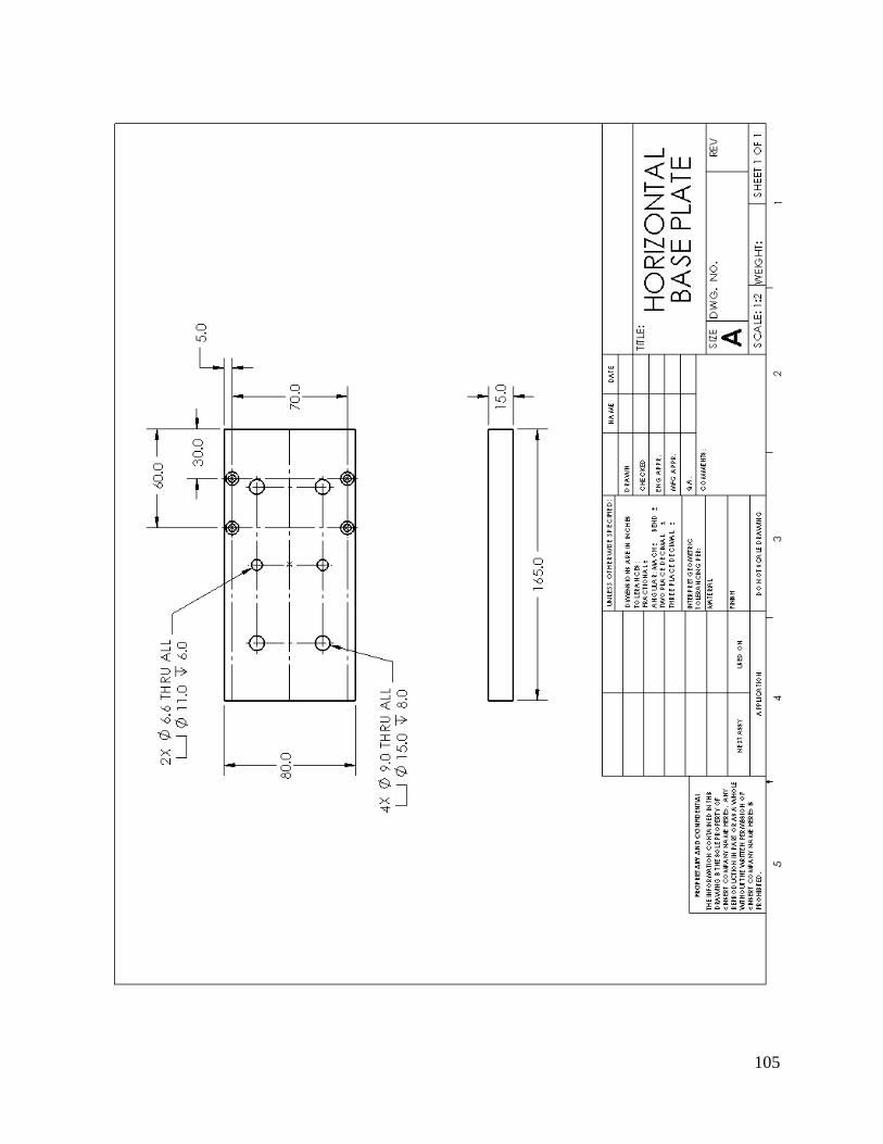
105

106

107

108

109

110

111
Appendix D: Product Testing Results
Figure 54: Sample 2-Load versus Time
Figure 55: Sample 3-Load versus Time
Figure 56: Sample 4-Load versus Time

112
Figure 57: Sample 5-Load versus Time
Figure 58: Sample 6-Load versus Time
Figure 59: Sample 7-Load versus Time

113
Figure 60: Sample 8-Load versus Time
Figure 61: Sample 2-Load versus Extension

114
Figure 62: Sample 3-Load versus Extension
Figure 63: Sample 4-Load versus Extension

115
Figure 64: Sample 5-Load versus Extension
Figure 65: Sample 6-Load versus Extension

116
Figure 66: Sample 7-Load versus Extension
Figure 67: Sample 8-Load versus Extension

117
Appendix E: Product Data Sheets
Table 3: Lee Spring's Wave Spring Specifications
Figure 68: VXB Linear Bearings Specifications

118
Table 4: Ledex Solenoid Duty Cycle

119
Figure 69: Ledex Solenoid Specifications

120
7. Bibliography
Cragun, John E. Lane Merger Apparatus. United States of America: Patent 5161665. 13
November 1992.
Glover, Charles G. Apparatus for Combining Articles from Plural Lanes into a Single Lane .
United States of America: Patent 4265356. 20 August 1981.
Haan, Ted W. High Volume Conveyor Sortation System . United States of America: Patent
7128197. 8 June 2005.
Harris, William O. Parallel Shaft Drive and Index Machine. United States of America: Patent
5176036. 1993.
Keyser, Carl A. Materials Science in Engineering. Columbus: Charles E. Merrill Publishing
Company, 1968.
"Ledex-Solenoids." 2011. Ledex. <http://www.ledex.com>.
"Lee Spring-Precision Stock and Custom Springs." n.d. Lee Spring.
<http://www.leespring.com>.
"McMaster Carr." 2011. <http://www.mcmaster.com/#>.
"Media Info." 2008-2010. Geneva Wheel Design: A Wonderful Intermittent Motion Mechanism.
2011 <http://www.meadinfo.org/2009/05/geneva-wheel-design.html>.
"Newark." 2011. <http://www.newark.com>.
Shackleford, Geoffrey G. Gripper Mechanism. United States of America: Patent 4243257. 5
April 1979.
"Timing Belt Conveyors offer speeds up to 200 fpm." n.d. Thomas Net. 2011
<http://news.thomasnet.com/fullstory/Timing-Belt-Conveyors-offer-speeds-up-to-200-
fpm-451835>.

121
"VXB Ball Bearings." 2011. <http://www.vxb.com>.
"Wise Tool Blog." 14 June 2010. Type of Mechanical Stamping Presses and its Application.
2011 <http://www.wisetoolblog.com/type-of-mechanical-stamping-presses-and-it-
application/>.