product information pi 25.3 crown-type tool turret …4 pi 25.3 e crown-type tool turret series 170...
TRANSCRIPT

PI 25.3 e
Product information PI 25.3
Crown-type tool turret0.5.170.1xx
See price list P57
2008-05-30


3PI 25.3 e
Tool turret
Description . . . . . . . . . . . . . . . . . . . . . . . . . . . . . . . . . . . . . . . . . . . . . . . . . . . . . . . . . . . 4
Technical data. . . . . . . . . . . . . . . . . . . . . . . . . . . . . . . . . . . . . . . . . . . . . . . . . . . . . . . . . 6
Dimensions . . . . . . . . . . . . . . . . . . . . . . . . . . . . . . . . . . . . . . . . . . . . . . . . . . . . . . . . . . 10
Precision/Type of protection . . . . . . . . . . . . . . . . . . . . . . . . . . . . . . . . . . . . . . . . . . . . . 11
Drive motors . . . . . . . . . . . . . . . . . . . . . . . . . . . . . . . . . . . . . . . . . . . . . . . . . . . . . . . . . 14
Drives (examples) . . . . . . . . . . . . . . . . . . . . . . . . . . . . . . . . . . . . . . . . . . . . . . . . . . . . . 16
Processing (examples) . . . . . . . . . . . . . . . . . . . . . . . . . . . . . . . . . . . . . . . . . . . . . . . . . 19
Spindle heads
Specifications . . . . . . . . . . . . . . . . . . . . . . . . . . . . . . . . . . . . . . . . . . . . . . . . . . . . . . . . 21
Spindle heads 0° selection . . . . . . . . . . . . . . . . . . . . . . . . . . . . . . . . . . . . . . . . . . . . . . 22
Admissible loads . . . . . . . . . . . . . . . . . . . . . . . . . . . . . . . . . . . . . . . . . . . . . . . . . . . . . . 24
Spindle heads 90° selection . . . . . . . . . . . . . . . . . . . . . . . . . . . . . . . . . . . . . . . . . . . . . 27
Precision . . . . . . . . . . . . . . . . . . . . . . . . . . . . . . . . . . . . . . . . . . . . . . . . . . . . . . . . . . . . 29
Ordering details
Crown-type tool turret . . . . . . . . . . . . . . . . . . . . . . . . . . . . . . . . . . . . . . . . . . . . . . . . . . 30
Spindle heads . . . . . . . . . . . . . . . . . . . . . . . . . . . . . . . . . . . . . . . . . . . . . . . . . . . . . . . . 31
If necessary, request: Project Planning Guide PA 25.3
NOTE:The information contained in this product information is based on details available at the time of printing. We explicitly reserve the right to make changes arising out of constant further development.
Contents
Mounting configurations . . . . . . . . . . . . . . . . . . . . . . . . . . . . . . . . . . . . . . . . . . . . . . . . 12
Radial drive shaft load . . . . . . . . . . . . . . . . . . . . . . . . . . . . . . . . . . . . . . . . . . . . . . . . . 18
4 PI 25.3 e
Crown-type tool turret series 170
are particularly suitable for
} Processing stations of transfer lines and revolving phased machine tools.
} High-speed processing with tool speeds of 15 000 min-1
and higher.
} Processing sequences with very short times between machining.
Specifications
} Bi-directional tool turret and tool drive with only one motor.
} SAUTER high-performance synchronous motors or commercially available spindle motors can be employed as drive units.
} Only the tool in working position is driven.Thus causing only a minimum power loss.
} High torque especially when processing with multi-spindle drill heads.
} Tool turret slewing axle at 45° to the tool axis - great freedom of movement to neighbouring tools.
} Secure locking of the rotating head with hydraulically activated triple Hirth toothed wheel work.
} All tool spindles protected against cuttings and cooling lubricant by means of supported by sealing air labyrinth seals.
} Cooling lubricant supply
• externally through the spindle head housing or
• internally through the tool spindle
• minimal quantity cooling lubrication
} Housing shape to the RIGHT or LEFT for free access to the electrics.
} Flange or leg fastening.
Description

5PI 25.3 e
45°
Tool turret slewing axis
Spindle heads
Tool turret rotating head
Space for electrics for limit switches andconnecting terminals
Tool axisActive toolin working position
Housing
Description
6 PI 25.3 e
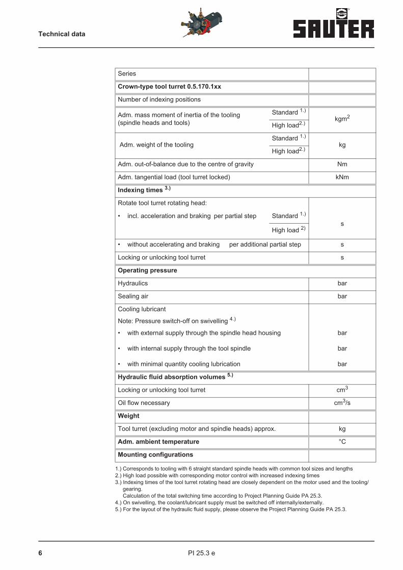
1.) Corresponds to tooling with 6 straight standard spindle heads with common tool sizes and lengths2.) High load possible with corresponding motor control with increased indexing times3.) Indexing times of the tool turret rotating head are closely dependent on the motor used and the tooling/
gearing.Calculation of the total switching time according to Project Planning Guide PA 25.3.
4.) On swivelling, the coolant/lubricant supply must be switched off internally/externally.5.) For the layout of the hydraulic fluid supply, please observe the Project Planning Guide PA 25.3.
Series
Crown-type tool turret 0.5.170.1xx
Number of indexing positions
Adm. mass moment of inertia of the tooling(spindle heads and tools)
Standard 1.)
kgm2
High load2.)
Adm. weight of the tooling Standard 1.)
kgHigh load2.)
Adm. out-of-balance due to the centre of gravity Nm
Adm. tangential load (tool turret locked) kNm
Indexing times 3.)
Rotate tool turret rotating head:
• incl. acceleration and braking per partial step
Standard 1.)
sHigh load 2)
• without accelerating and braking per additional partial step s
Locking or unlocking tool turret s
Operating pressure
Hydraulics bar
Sealing air bar
Cooling lubricant
Note: Pressure switch-off on swivelling 4.)
• with external supply through the spindle head housing
• with internal supply through the tool spindle
• with minimal quantity cooling lubrication
bar
bar
bar
Hydraulic fluid absorption volumes 5.)
Locking or unlocking tool turret cm3
Oil flow necessary cm3/s
Weight
Tool turret (excluding motor and spindle heads) approx. kg
Adm. ambient temperature °C
Mounting configurations
Technical data
7PI 25.3 e
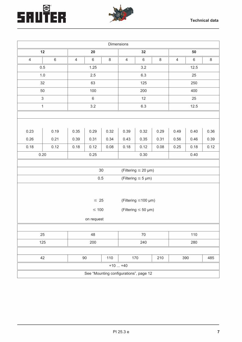
Dimensions
12 20 32 50
4 6 4 6 8 4 6 8 4 6 8
0.5 1.25 3.2 12.5
1.0 2.5 6.3 25
32 63 125 250
50 100 200 400
3 6 12 25
1 3.2 6.3 12.5
0.23 0.19 0.35 0.29 0.32 0.39 0.32 0.29 0.49 0.40 0.36
0.26 0.21 0.39 0.31 0.34 0.43 0.35 0.31 0.56 0.46 0.39
0.18 0.12 0.18 0.12 0.08 0.18 0.12 0.08 0.25 0.18 0.12
0.20 0.25 0.30 0.40
30
0.5 (Filtering � 5 µm)
� 25
� 100
on request
(Filtering �100 µm)
(Filtering � 50 µm)
25 48 70 110
125 200 240 280
42 90 110 170 210 390 485
+10 ... +40
See “Mounting configurations”, page 12
Technical data
(Filtering � 20 µm)

8 PI 25.3 e
1.) Please observe information on control the Project Planning Guide PA 25.3.
2.) Higher speeds on request.3.) Mzul is the permitted peak loading for the gearbox.
a The torque must be reduced to the specified value at the motor inverter. The gearbox ratio must be taken into account. The usable power data depend on the power curve of the motor type used. The permitted torque can be used with jolt-free machining.For machining operations where severe jolting occurs, for example with knife-head milling cutters, etc., greatly reduced drive torque must be used to avoid overloading the gearbox.
Series
Crown-type tool turret 0.5.170.1xx
Number of indexing positions
Slewing operation 1.)
Rated speed at the drive shaft min-1
Adm. torque at the drive shaft when accelerating and braking Nm
Transmission ratioDrive shaft / tool turret rotating head iRev=nA/nD
Mass moment of inertia of rotating head and tool turret gear(relating to the drive shaft) 10-4kgm2
Cutting operation
Max. adm. drive speed 2.) min-
Max. adm. drive torque 3.) Nm
Max. adm. drive performance kW
Transmission ratioDrive shaft / tool coupling iW=nA/nW
Mass moment of inertia of the drive spindle 10-4kgm2
Coupling profile DIN 5480
SAUTER spindle heads for this purpose 0.5.934.1..0.5.934.2..
Technical data

9PI 25.3 e
Dimensions
12 20 32 50
4 6 4 6 8 4 6 8 4 6 8
1000 1000 1000 720
12 20 15 35 70
12 12 16 12 16 12 16
4.5 20 32 62 86 220 320
15000 12000 12000 9000
40 80 150 300
6 10 16 25
1 1 1 1
1 2.5 12 38
16 x 0.8 20 x 0.8 30 x 1.25 37 x 1.25
.. 03 .. 04 .. 06 .. 08
Technical data

10 PI 25.3 e
Depicted: RIGHT version.The dimensions are identical for both the RIGHT and LEFT versions
Dimensions in mm
Series Dimensions
Crown-type tool turret 0.5.170.1xx 12 20 32 50
Number of indexing positions 4 6 4 6 8 4 6 8 4 6 8
B 105 152 194 185 236 240 306
C 95 108 130 170
D 65 80 98 130
E 8 10 12 16
dia. F 210 285 345 350 425 460 550
G 105 141 171 171 207 222 269
H 90 120 140 180
J 93 134 165 216
K 210 280 350 460
dia. L 35 45 60 80
dia. M 90 120 140 190
dia. N 25 28 32 40
O 30 35 46 50
CB
ØF
GØ
M
ØN
E
O
D
45°
K
ØL
JH
Dimensions
11PI 25.3 e
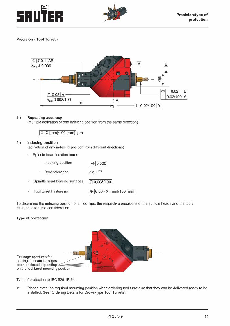
Precision - Tool Turret -
1.) Repeating accuracy(multiple activation of one indexing position from the same direction)
2.) Indexing position(activation of any indexing position from different directions)
• Spindle head location bores
To determine the indexing position of all tool tips, the respective precisions of the spindle heads and the tools must be taken into consideration.
Type of protection
Type of protection to IEC 529: IP 64
} Please state the required mounting position when ordering tool turrets so that they can be delivered ready to be installed. See “Ordering Details for Crown-type Tool Turrets”.
– Indexing position
– Bore tolerance dia. LH6
• Spindle head bearing surfaces
• Tool turret hysteresis
ØL
H6
Øj6
X
.
.
Drainage apertures for cooling lubricant leakagesopen or closed dependingon the tool turret mounting position
Precision/type ofprotection

12 PI 25.3 e
Explanation of mounting configurations:
} Further mounting positions on request
Direction to horizontal:
+Z-axis 0° - horizontal
+Y-axis 90° - vertically upwards
+Z-axis 0° - horizontal
+Y-axis 270°- vertically downwards
+Z-axis 0° - horizontal
+Y-axis 180° - horizontal
RIGHT-HANDED Version
+Z-axis 180° - horizontal
+Y-axis 0° - horizontal
Left-HANDED Version
At first rotate crown-type tool turret at „+Z“ (angle γ).
Then rotate on the tool axis „Z“ at „+Y“ (angle β).
+Y
0°+Z
γβ
+Z
+Y
+Z
+Y
+Y
Mountingconfigurations
+Z
+Z +Y

13PI 25.3 e
Tool turret - drive shaft
Version I - for cooling lubricant feed through the hollow motor shaft(Direct motor mounting)
Version II - for mounting a cooling lubricant rotary transmission lead through(SAUTER synchronous motor / motor mounting axially displaced)
Dimensions in mm
Series Dimensions
Crown-type tool turret 0.5.170.1xx 12 20 32 50
d10H8 dia. 12 dia. 14 dia. 16 dia. 18
H18 11.5 12 15 20
L10 52 72 62 69
d12H6 dia. 18
d13 M 16 x 1.5 left
L11 18
L12 8
L10
H1Hub
d 10
Hub H1
d 13
d 12
L12
L11
Mountingconfigurations
14 PI 25.3 e
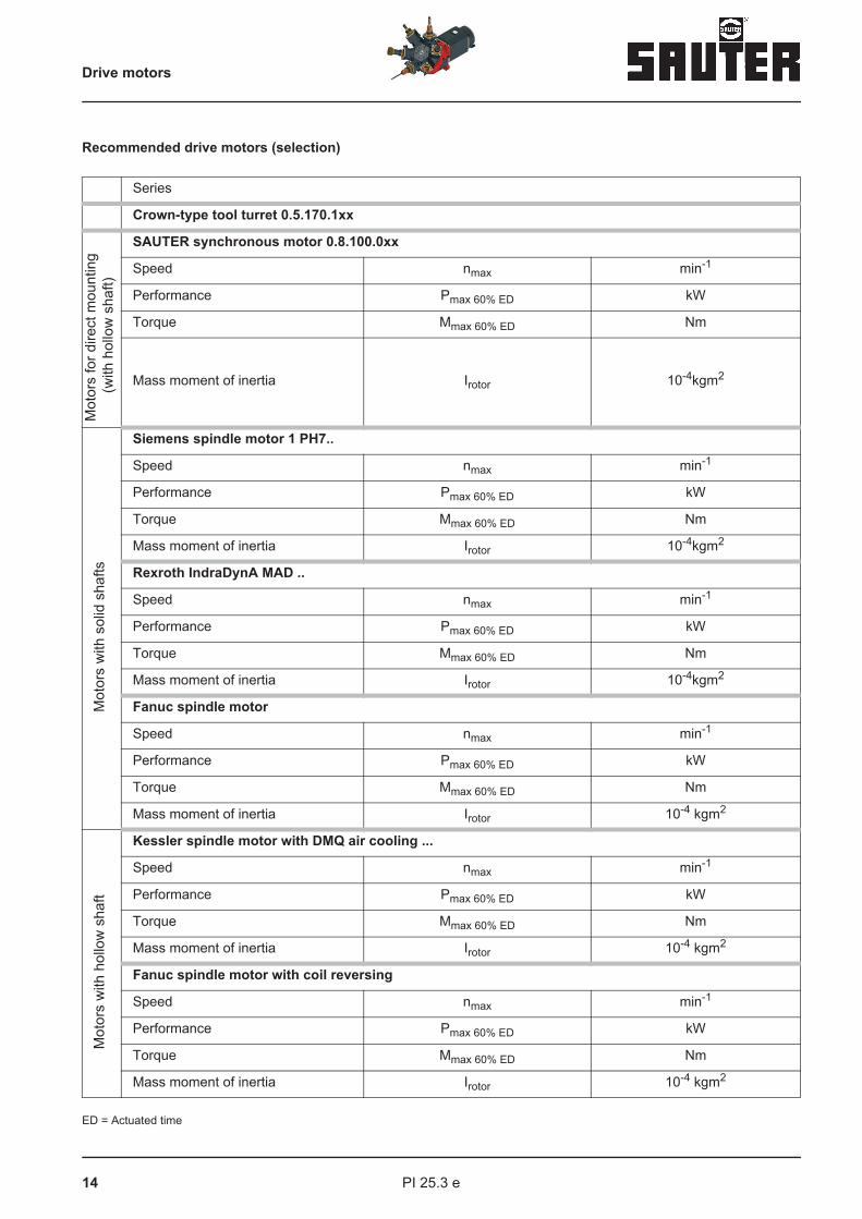
Recommended drive motors (selection)
ED = Actuated time
Series
Crown-type tool turret 0.5.170.1xx
Mot
ors
for d
irect
mou
ntin
g (w
ith h
ollo
w s
haft)
SAUTER synchronous motor 0.8.100.0xx
Speed nmax min-1
Performance Pmax 60% ED kW
Torque Mmax 60% ED Nm
Mass moment of inertia Irotor 10-4kgm2
Mot
ors
with
sol
id s
hafts
Siemens spindle motor 1 PH7..
Speed nmax min-1
Performance Pmax 60% ED kW
Torque Mmax 60% ED Nm
Mass moment of inertia Irotor 10-4kgm2
Rexroth IndraDynA MAD ..
Speed nmax min-1
Performance Pmax 60% ED kW
Torque Mmax 60% ED Nm
Mass moment of inertia Irotor 10-4kgm2
Fanuc spindle motor
Speed nmax min-1
Performance Pmax 60% ED kW
Torque Mmax 60% ED Nm
Mass moment of inertia Irotor 10-4 kgm2
Mot
ors
with
hol
low
sha
ft
Kessler spindle motor with DMQ air cooling ...
Speed nmax min-1
Performance Pmax 60% ED kW
Torque Mmax 60% ED Nm
Mass moment of inertia Irotor 10-4 kgm2
Fanuc spindle motor with coil reversing
Speed nmax min-1
Performance Pmax 60% ED kW
Torque Mmax 60% ED Nm
Mass moment of inertia Irotor 10-4 kgm2
Drive motors

15PI 25.3 e
Drive motors
Dimensions
12 20 32 50
..12-125306 ..20-118129 ..32-118139 ..50-118159
10000 12000 12000 9000
16 23 26 52
32 37 75 150
13 50 270 477
.. 101 .. 103 .. 107 .. 133
9000 9000 9000 8000
4.5 8.5 11 15
28.5 40.5 70 145
170 170 290 760
.100 B .100 C .100 D .132 C
9000 9000 9000 7500
5.2 9.0 11 22
33 57 90 140
190 284 378 1150
α2 α3 α6 α6 α8 α15
8000 8000 8000 8000 6000 6000
3.7 5.5 7.5 7.5 11 18
23 35 48 48 70 120
78 148 215 215 275 900
... 100.AK4AG ... 100.AM4AG ... 100.AS4AG
12000 12000 9000
7.5 12.5 16
36 60 76
140 230 330
αT2/15000 αT6/12000 αT6/12000 αT15/10000
15000 12000 12000 9000
4.0 7.5 7.5 18.5
12.5 48 48 110
78 179 179 550

16 PI 25.3 e
Direct drive with SAUTER - synchronous motor
Coaxial drive with flange motor and coupling
a NOTE:In the case of direct drive, please observe the admissible deviation of position of the motor shaft to the tool turret drive shaft for the coupling!
Slide
SAUTER-synchronous motor
Cooling lubricant-rotary transmission **lead through
Slide
Motor flange Drive motorwith transmitter
hollow shaftsystem and
Cooling lubricant-rotary transmission lead through **
Cooling lubricant-transfer nipple
Coupling
Drives (examples)
**

17PI 25.3 e
Drives (examples)
Drive with toothed-belt gearing
* e.g. Goodyear-Eagle, or similar** e.g. Make Deublin, GAT, or similar
High performance toothed belt drive*i=0.5/1/2
Drive motorwith transmitter system
Cooling lubricant-rotary transmission **lead through
Proximity switch for drive reference point(if necessary)
Slide

18 PI 25.3 e
Admissible radial load of the standard drive shaft through toothed belt lateral force
0.5.170.112 0.5.170.120
0.5.170.132 0.5.170.150
L
X
FQ
0 5 10 15 20 25 30
X [mm]
FQ
[k
N]
1000 1/min
5000 1/min
10000 1/min
15000 1/min
1.20
1.00
0.80
0.60
0.40
0.20
0.000
0 5 10 15 20 25 30 35
X [mm]
FQ
[k
N]
1000 1/min
6000 1/min
12000 1/min
1.8
1.6
1.4
1.2
0.8
1
0.6
0.4
0.2
0
1
2
0 5 10 15 20 25 30 35 40 45
X [mm]
FQ
[k
N]
1000 1/min
5000 1/min
10000 1/min
<
2.5
1.5
0.5
0
1
2
3
0 5 10 15 20 25 30 35 40 45
X [mm]
FQ
[k
N]
1000 1/min
4000 1/min
8000 1/min
3.5
2.5
1.5
0.5
Drive shaftradial load
Nominal bearing service life 20 000 h

19PI 25.3 e
Processing (examples)Hints:
} The performance of the tool turrets during cutting are most of all limited by the following factors:
• Performance of the selected driving motor
• Degree of uniformity of the cutting forces
• Tool length
• Bearing of the tool spindles
• Size of the tool holding fixture
} The cutting values listed below are possible maximum loads at approx. 40% ED within a load group with different performance requirements.
1.) Spindle head bearing: tandem <<0>, distance "long"2.) Tool length: “short”Take care in the case of processing involving shock loads. Possible great reduction (50% or more!) of the max. possible cutting values required!When milling use hob cutters with as many teeth as possible for uniform cutting forces.
Processing (examples)
Tapping BoringHSS twist drills
BoringHard alloy short hole drills
Facemilling
d x P[mm] x [mm]
d x f[mm] x [mm/rotation]
d x f[mm] x [mm/rotation]
d x e x fz[mm] x [mm] x [mm/tooth]
Tool turret dimensions 0.5.170.1xx 12 20 32 50
Motor used Siemens 1 PH7... ..101 ..103 ..107 ..133
Mmax 40 % ED Nm 35 50 85 180
Material of the work piece: St 60, tensile strength Rm ≤ 600 N/mm2
Tapping d x P M 10 x 1.5 M 12 x 1.75 M 16 x 2 M 24 x 3
Drilling with twist drill d x f 12 x 0.2 20 x 0.21) 25 x 0.21) 32 x 0.31)
Drilling with HM short hole drills d x f 25 x 0.1 32 x 0.121) 40 x 0.161) 45 x 0.21)
Milling with milling head 2) d x e x fz 40 x 2.5 x 0.16 50 x 3 x 0.161) 63 x 3 x 0.21) 100 x 3 x 0.251)
Material of the work piece: Aluminium alloy, hardness ≤ 1000 HB
Tapping d x P M 20 x 2.5 M 27 x 3 M 33 x 3.5 M 42 x 4.5
Drilling with twist drill d x f 25 x 0.16 40 x 0.161) 40 x 0.251) 50 x 0.251)
Milling with milling head 2) d x e x fz 40 x 4 x 0.25 50 x 5 x 0.251) 63 x 6 x 0.31) 100 x 8 x 0.31)
d
P df
d
f
e
d
fz
Processing (examples)

20 PI 25.3 e
Notes:

21PI 25.3 e
Spindle heads of series 0.5.934xxx
are primarily intended for use on SAUTER crown-type tool turrets of series 0.5.170.1..
} Bearing in precision spindle bearings in -O- or tandem-O-arrangement,medium initial tension
} Permanent grease lubrication
} Non-wearing labyrinth seal with sealing air support
} Cooling lubricant supply
• externally through the spindle head housing or
• internally through the tool spindle
} Spindle twisting safety device (pat.) in uncoupled state
} Very true and well balanced running
} Tool holding fixure in the spindle:for HSK/Mapal clamping system
Options:
} Special tool locations
} Spindle bearings (selection):
• for high speed running
• for high load
• for special demands
} Further options on request:
• Spindle heads with ratio 1
• Multi-spindle drilling heads
<>
Specifications

22 PI 25.3 e
DimensionsCrown-type tool turret
Tool holding fixture1)
Bearing
arrangementOrder number
170.112
HSK 32-C < O > 0.5.934.103-107 900
HSK 40-C < O > 0.5.934.103-108 400
HSK 40-C << O > 0.5.934.103-117 264
170.120
HSK 40-C < O > 0.5.934.104-103 691
HSK 40-C << O > 0.5.934.104-103 803
HSK 50-C < O > 0.5.934.104-103 692
HSK 50-C << O > 0.5.934.104-104 090
HSK 50-C << O > 0.5.934.104-103 804
170.132
HSK 50-C < O > 0.5.934.106-103 960
HSK 63-C < O > 0.5.934.106-103 800
HSK 63-C << O > 0.5.934.106-103 832
HSK 63-C << O > 0.5.934.106-103 840
170.150
HSK 63-C < O > 0.5.934.108-109 077
HSK 63-C << O > 0.5.934.108-109 154
HSK 80-C < O > 0.5.934.108-104 696
HSK 80-C << O > 0.5.934.108-104 360
HSK 100-C < O > 0.5.934.108-109 091
HSK 100-C << O > 0.5.934.108-123 032
L
Spindle heads 0°Selection

23PI 25.3 e
Spindle heads 0°Selection
Application recommendation:
Bearing arrangement <<0> – at higher loads
Suitable for IK dry running
1.) For Mapal, type KS..-07 clamping units, order the unit and guard ring separately as necessary.
2.) High speed only for short term operation (≤ 10 % ED - 5 min.)
3.) Relating to tool turret slewing axis
Speed Mass moment of inertia Weight ofSpindle head Dimensions
nadm 2) Spindle Spindle head 3) m L
[min-1] [10-4 kgm2] [kgm2] [kg] [mm]
15000 2.6 0.05 3 100
15000 2.8 0.05 3 100
15000 2.8 0.05 3 100
12000 8.0 0.15 6.5 125
10000 10.0 0.21 8.5 155
12000 8.5 0.15 6.5 125
10000 8.5 0.15 6.5 125
10000 10.5 0.21 8.5 155
10000 24.0 0.34 10.5 138
10000 26.0 0.34 10.5 138
8000 26.0 0.34 10.5 138
8000 34.0 0.5 13.5 180
8500 80 1.34 25 190
7000 80 1.34 25 190
8500 82 1.34 25 190
7000 82 1.34 25 190
8500 104 1.34 25 200
7000 104 1.34 25 200

24 PI 25.3 e
Admissible axial force when boring
Charac-teristic line no.
Bearing arrangement
Nominal bearing life
Lh [h]
1 Standard 4000
2 Tandem 4000
3 Standard 8000
4 Tandem 8000
0.5.934.103 0.5.934.104
0.5.934.106 0.5.934.108
Fax
1000
3000
5000
7000
9000
11000
13000
15000
n [1/min]
Fa
x [
kN
]
1
2
4
3
3.50
3.00
2.50
2.00
1.50
1.00
0.50
0.00
1000
2000
3000
4000
5000
6000
7000
8000
9000
10000
11000
12000
n [1/min]
Fa
x [
kN
]
1
2
3
4
6.00
5.00
4.00
3.00
2.00
1.00
0.00
1000
2000
3000
4000
5000
6000
7000
8000
9000
10000
11000
12000
n [1/min]
Fa
x [
kN
]
2
4
1
3
7.00
6.00
5.00
4.00
3.00
2.00
1.00
0.00
1000
2000
3000
4000
5000
6000
7000
8000
9000
10000
11000
12000
n [1/min]
Fa
x [
kN
]
1
2
3
4
10.00
9.00
8.00
7.00
6.00
5.00
4.00
3.00
2.00
1.00
0.00
Admissible loads
25PI 25.3 e
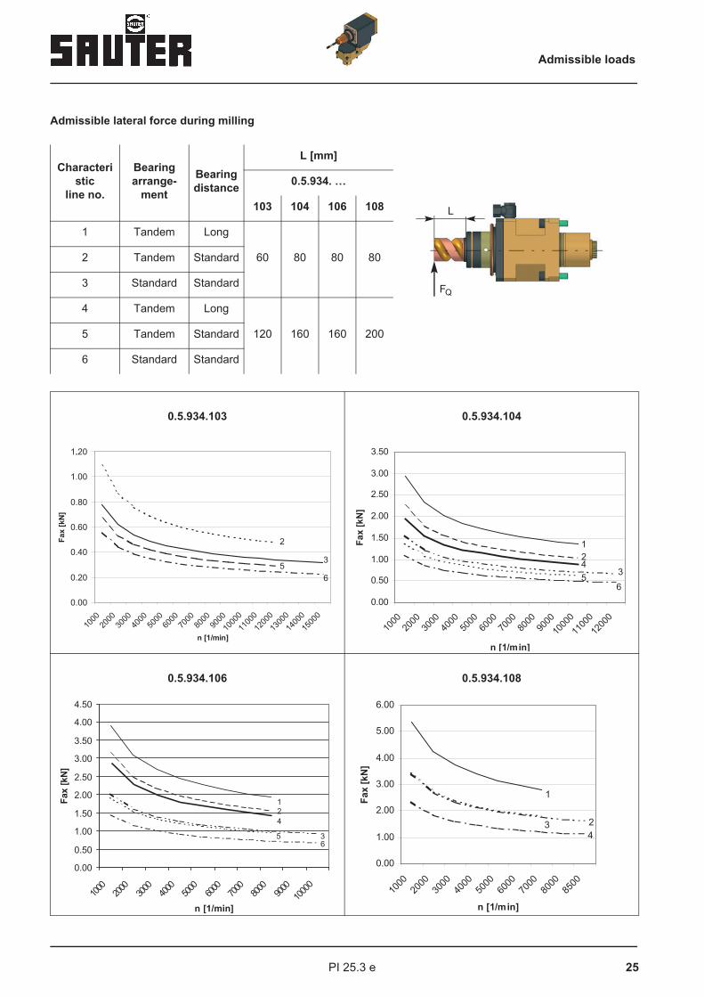
Admissible lateral force during milling
Characteristic
line no.
Bearing arrange-
ment
Bearing distance
L [mm]
0.5.934. …
103 104 106 108
1 Tandem Long
60 80 80 802 Tandem Standard
3 Standard Standard
4 Tandem Long
120 160 160 2005 Tandem Standard
6 Standard Standard
0.5.934.103 0.5.934.104
0.5.934.106 0.5.934.108
L
FQ
1000
2000
3000
4000
5000
6000
7000
8000
9000
10000
11000
12000
13000
14000
15000
n [1/min]
Fax [
kN
]
3
2
5
6
1..20
1.00
0.80
0.60
0.40
0.20
0.00
1000
2000
3000
4000
5000
6000
7000
8000
9000
10000
11000
12000
n [1/min]
Fa
x [
kN
]
1
2
34
5
6
3.50
3.00
2.50
2.00
1.50
1.00
0.50
0.00
1000
2000
3000
4000
5000
6000
7000
8000
9000
10000
n [1/min]
Fax [
kN
]
1
2
3
4
5
6
4.50
4.00
3.50
3.00
2.50
2.00
1.50
1.00
0.50
0.00
1000
2000
3000
4000
5000
6000
7000
8000
8500
n [1/min]
Fa
x [
kN
]
1
23
4
6.00
5.00
4.00
3.00
2.00
1.00
0.00
Admissible loads

26 PI 25.3 e
DimensionsCrown-type tool turret
Tool holdingfixture
Bearing
arrangementOrder number
170.112
for collet chuck DIN 6499-25 < O > 0.5.934.203-111 243
for collet chuck DIN 6499-25 < O > 0.5.934.203-111 244
HSK 40-C 1) 2) < O > 0.5.934.203-111 245
HSK 40-C 1) 2) < O > 0.5.934.203-111 246
170.120
for collet chuck DIN 6499-32 < O > 0.5.934.204-111 237
for collet chuck DIN 6499-32 < O > 0.5.934.204-111 238
HSK 50-C 1) 2) < O > 0.5.934.204-111 239
HSK 50-C 1) 2) < O > 0.5.934.204-111 240
170.132
for collet chuck DIN 6499-40 << O > 0.5.934.206-111 233
for collet chuck DIN 6499-40 << O > 0.5.934.206-111 235
HSK 63-C 1) 2) << O > 0.5.934.206-111 234
HSK 63-C 1) 2) << O > 0.5.934.206-111 236
170.150
for collet chuck DIN 6499-50 << O > 0.5.934.208-111 251
for collet chuck DIN 6499-50 << O > 0.5.934.208-111 252
HSK 80-C 1) 2) << O > 0.5.934.208-111 248
HSK 80-C 1) 2) << O > 0.5.934.208-111 249
L 2
L 1
Spindle heads 90°Selection
B

27PI 25.3 e
Operating pressure for cooling lubricant with internal and external feed: pmax = 25 bar
Suitable for IK dry running
1.) For Mapal, type KS..-07 clamping units, order the unit and guard ring separately as necessary.
2.) Minimum distance of the same spindle heads on the tool turret: 90°
3.) High speed only for short term operation (≤ 10 % ED - 5 min.)
4.) Relating to tool turret slewing axis
} Other versions of tool holder system, bearing types etc. on request
Note:
Speed Mass moment of inertia Weight ofSpindle head Dimensions
nadm 3) Spindle Spindle head 4) m L1 L2 B
[min-1] [10-4 kgm2] [kgm2] [kg] [mm] [mm] [mm]
8000 0.9 0.12 6 – 100 72
8000 0.9 0.22 8 – 160 72
8000 0.9 0.08 7.5 57.5 100 0
8000 0.9 0.15 10 57.5 160 0
8000 12 0.5 14 – 125 95
8000 12 0.92 18.5 – 200 95
8000 12 0.27 15 60 125 0
8000 12 0.58 21 60 200 0
8000 39 1.51 27.5 – 160 118
8000 39 2.66 34.5 – 250 118
8000 39 0.78 30.5 70 160 0
8000 39 1.42 36.5 70 250 0
6000 50 4.16 48 – 200 171
6000 50 7.71 64 – 320 171
6000 50 2.57 56 85 200 0
6000 50 5.09 73 85 320 0
Number of indexing positions of the crown-type tool turret 4 6 8
Max. number of the loading with spindle heads 90° 4 3 4
Spindle heads 90°Selection
28 PI 25.3 e
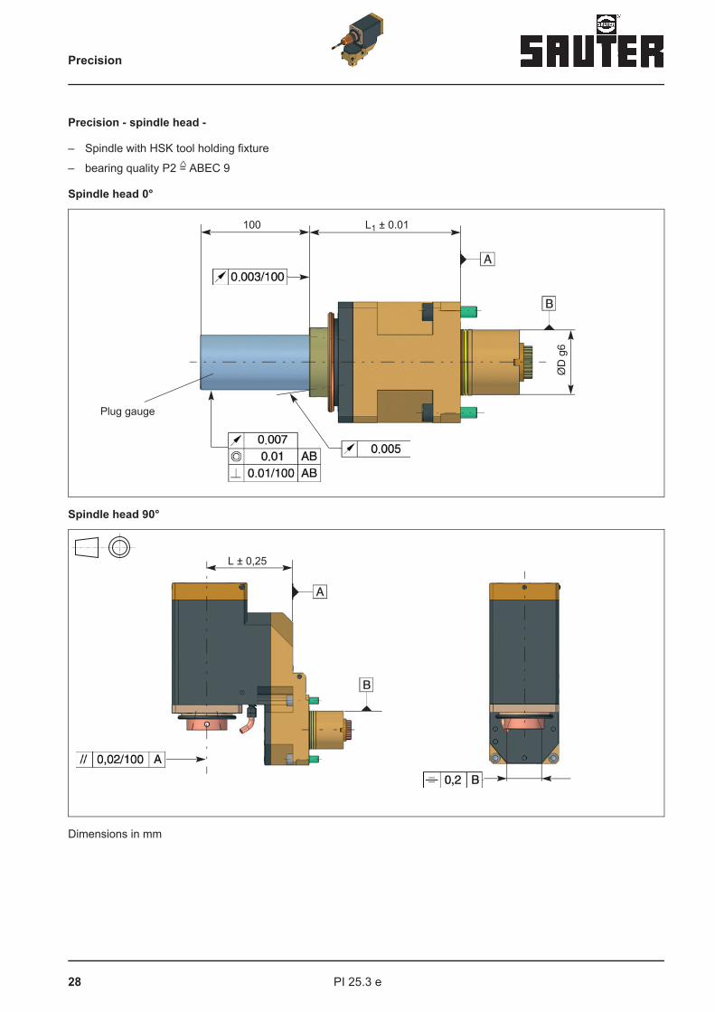
Precision - spindle head -
– Spindle with HSK tool holding fixture
– bearing quality P2 = ABEC 9
Spindle head 0°
Spindle head 90°
Dimensions in mm
100 L1 ± 0.01
ØD
g6
Plug gauge
L ± 0,25
Precision
29PI 25.3 e
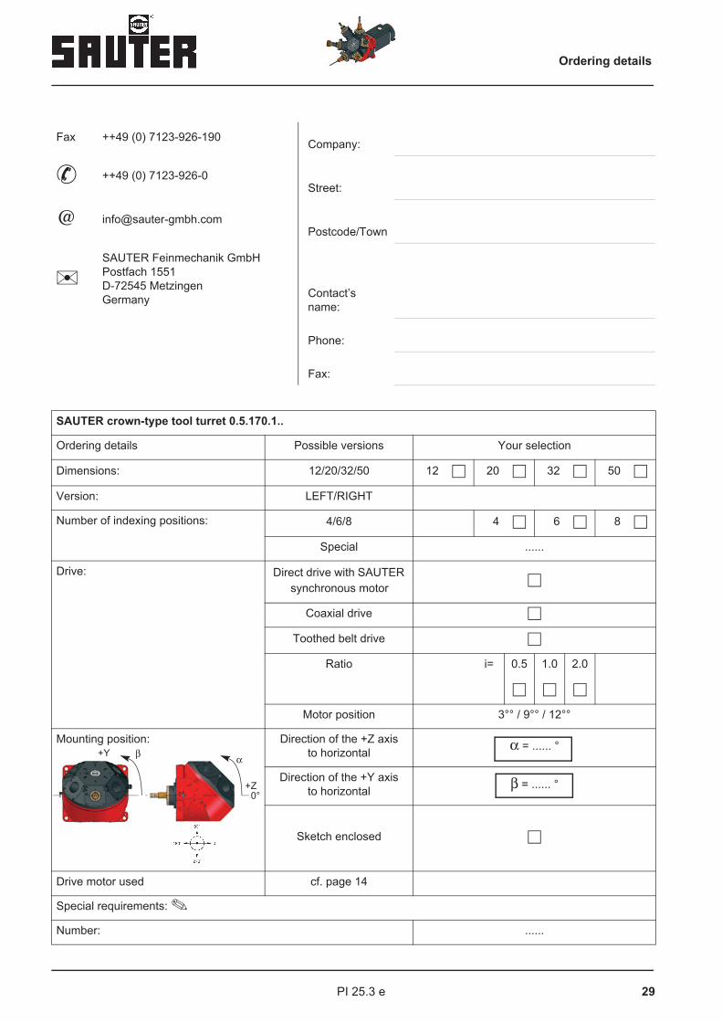
Fax ++49 (0) 7123-926-190 Company:
++49 (0) 7123-926-0Street:
@ [email protected]/Town
SAUTER Feinmechanik GmbHPostfach 1551D-72545 MetzingenGermany Contact’s
name:
Phone:
Fax:
SAUTER crown-type tool turret 0.5.170.1..
Ordering details Possible versions Your selection
Dimensions: 12/20/32/50 12 � 20 � 32 � 50 �
Version: LEFT/RIGHT
Number of indexing positions: 4/6/8 4 � 6 � 8 �
Special ......
Drive: Direct drive with SAUTER synchronous motor
�
Coaxial drive �
Toothed belt drive �
Ratio i= 0.5 1.0 2.0
� � �
Motor position 3°° / 9°° / 12°°
Mounting position: Direction of the +Z axisto horizontal α = ...... °
Direction of the +Y axisto horizontal β = ...... °
Sketch enclosed �
Drive motor used
Special requirements:
Number: ......
+Y
0°+Z
αβ
Ordering details
cf. page 14
30 PI 25.3 e
Fax ++49 (0) 7123-926-190 Company:
++49 (0) 7123-926-0Street:
@ [email protected]/Town
SAUTER Feinmechanik GmbHPostfach 1551D-72545 MetzingenGermany Contact’s
name:
Phone:
Fax:
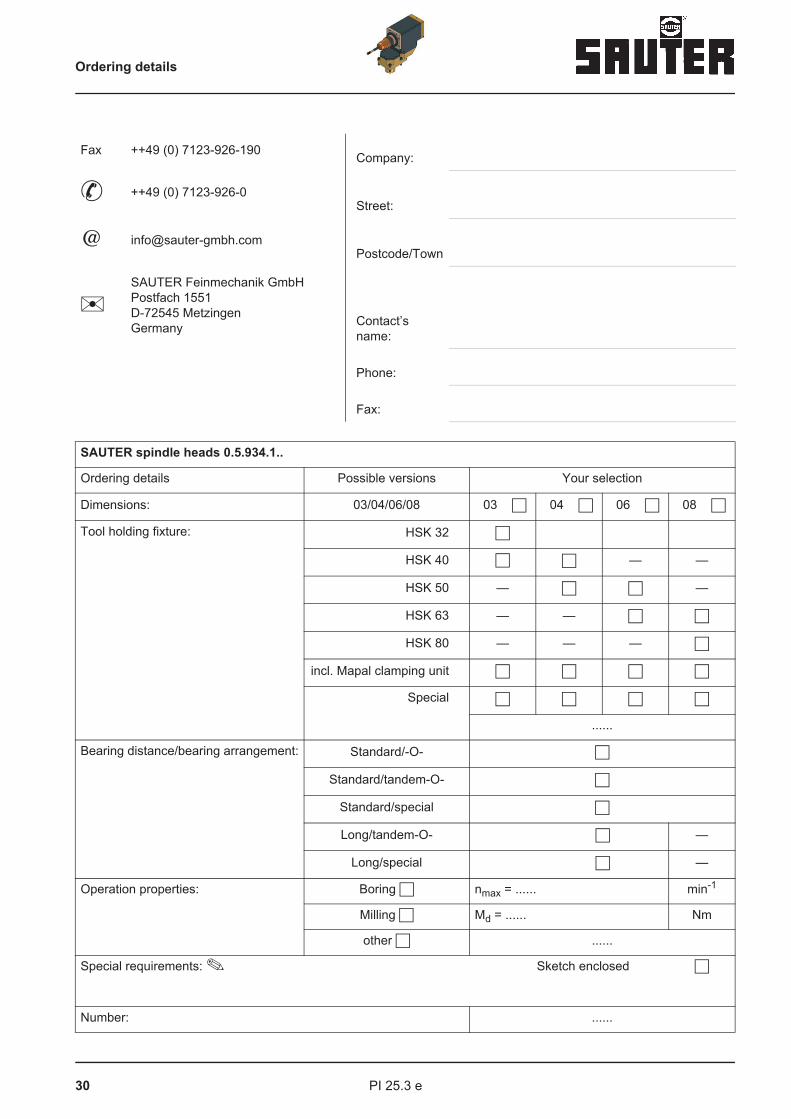
SAUTER spindle heads 0.5.934.1..
Ordering details Possible versions Your selection
Dimensions: 03/04/06/08 03 � 04 � 06 � 08 �
Tool holding fixture: HSK 32 �
HSK 40 � � — —
HSK 50 — � � —
HSK 63 — — � �
HSK 80 — — — �
incl. Mapal clamping unit � � � �
Special � � � �
......
Bearing distance/bearing arrangement: Standard/-O- �
Standard/tandem-O- �
Standard/special �
Long/tandem-O- � —
Long/special � —
Operation properties: Boring � nmax = ...... min-1
Milling � Md = ...... Nm
other � ......
Special requirements: Sketch enclosed �
Number: ......
Ordering details
31PI 25.3 e
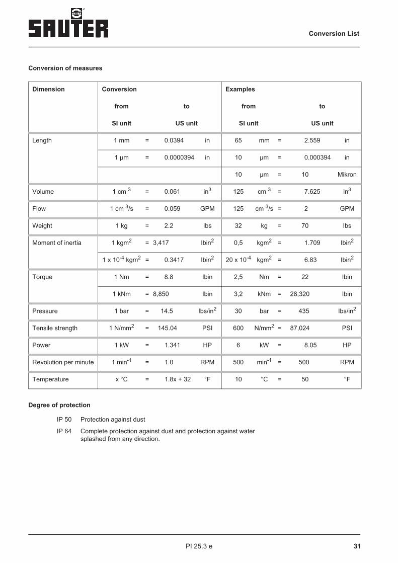
Conversion of measures
Degree of protection
IP 50 Protection against dust
IP 64 Complete protection against dust and protection against watersplashed from any direction.
Dimension Conversion Examples
from to from to
SI unit US unit SI unit US unit
Length 1 mm = 0.0394 in 65 mm = 2.559 in
1 µm = 0.0000394 in 10 µm = 0.000394 in
10 µm = 10 Mikron
Volume 1 cm 3 = 0.061 in3 125 cm 3 = 7.625 in3
Flow 1 cm 3/s = 0.059 GPM 125 cm 3/s = 2 GPM
Weight 1 kg = 2.2 Ibs 32 kg = 70 Ibs
Moment of inertia 1 kgm2 = 3,417 Ibin2 0,5 kgm2 = 1.709 Ibin2
1 x 10⁻⁴ kgm2 = 0.3417 Ibin2 20 x 10-4 kgm2 = 6.83 Ibin2
Torque 1 Nm = 8.8 Ibin 2,5 Nm = 22 Ibin
1 kNm = 8,850 Ibin 3,2 kNm = 28,320 Ibin
Pressure 1 bar = 14.5 Ibs/in2 30 bar = 435 Ibs/in2
Tensile strength 1 N/mm2 = 145.04 PSI 600 N/mm2 = 87,024 PSI
Power 1 kW = 1.341 HP 6 kW = 8.05 HP
Revolution per minute 1 min-1 = 1.0 RPM 500 min-1 = 500 RPM
Temperature x °C = 1.8x + 32 °F 10 °C = 50 °F
Conversion List