product information phased ac drives for battery supply
TRANSCRIPT

powersolutions.danfoss.com
MAKING MODERN LIVING POSSIBLE
Product Information
AC Drives forBattery Supply
Phased Out Products

Product Information dACi® - EL: Product Information
BLN-10294 • Rev BA • Sep 20132
Product Matrix OverviewSeries ASeries A is the first generation of our AC-controllers. It is based on a modular concept, which allows amaximum on flexibility. The controllers are available for traction drives, hydraulic pump drives andelectronic steering.This series will be replaced by the newer series B, C, D and E.
Size 24V 48V 80VA1 60A 25A 20AA2 120A 50A 40AA4 240A 100A 80AA6 360A 150A 120AA8 480A 200A 160A
A10 250A 200AA12 300A 240AA14 350A 280AA16 400A 320AA18 450A 360AA20 500A 400AA22 550A 440AA24 600A 480A
Series BSeries B is the first type of the second generation of our AC-controllers.It is optimized for small pedestrian trucks and other small drives with 24V battery supply voltage.Special versions for 12V and 36V are available.
Size 12V 24V 36VB1 60A 60A 60AB2 120A 120A 120A
Series CSeries C is optimized for battery powered material handling vehicles of the small and medium powerrange, like pedestrian trucks (walkies), order pickers and small lift trucks. The 80V version is mainlyused for auxiliary hydraulic pump drives in bigger trucks.
Size 24V 36V 48V 80VC2 120A 100A 75A 40AC3 180A 150A 112A 60AC4 240AC6 360A 300A 225A 120AC8 480A 400A 300A 160A
Options:
-H Hydraulic unit: All electronic components and driver-outputs for a hydraulic system withproportional lifting and lowering are included.
-C with CAN-Bus interface
-AGV Special version for automatic guided vehicles (AGV)
Phased Out Products

Product Information dACi® - EL: Product Information
BLN-10294 • Rev BA • Sep 2013 3
Series DSeries D is optimized for battery powered material handling vehicles of the medium and high powerrange, like counterbalance trucks, reach trucks and high level order pickers. A special version for dualdrive application is available. CAN-Bus is optionally.
Size 24V 36V 48V 80VD8 480A 400A 300A 160A
(D10) 600A 500A 375A 200AD12 (720A) 600A 450A 240AD16 600A 320A
(D20) 750A 400AD24 480A
D24x 600A
Options:
-C with CAN-Bus interface
-ZM Dual drive, master
-ZS Dual drive, slave
Series ESeries E is the new generation of electronic steering controllers.
Size 24V 36V 48V 80VE1 60A 50AE2 120A 100A 75A 40AE3 180A 150A 112A 60AE3x 75A
Remarks:All indicated current values mean maximum current.(…) : These types are not in series production yet.
Type Identification:
Options
Series: A, B, C, D, E
G= Ground plate, K= finned-type heatsink
Maximum current
Nominal battery voltage
Application: TA= traction, H=hydraulic pump, EL=electronic steering
drive system with AC-induction motor
dACi-TA 24/240 GC-HC
Phased Out Products

Product Information dACi® - EL: Product Information
BLN-10294 • Rev BA • Sep 20134
Series E
dACi - ELElectronic Steering Control
with AC Technology
Phased Out Products

Product Information dACi® - EL: Product Information
BLN-10294 • Rev BA • Sep 2013 5
dACi-EL ...
... is an electronic steering controller with AC-technology
dACi-EL operates without any mechanicalconnection between the steering assembly andthe drive wheels. The set value for the steeringangle is transmitted from an incremental encoderthat is attached to a steering wheel, from ajoystick or from a potentiometer that is attached toa tiller. Also a superordinated controller cantransfer the set value via analogue or serialinterface (RS485 or CAN).
A digital closed loop controller ensures immediatesteering movement synchronized exactly to themovement of the steering wheel. The systemshigh dynamics and steering accuracy gives thefeeling of a rigid coupling between steeringassembly and drive wheels.
As actuator a maintenance-free AC-inductionmotor is used. The necessary three phasesinusoidal current is generated by an inverter,powered by the supply-battery.
Features:♦ Closed loop angle control
Gives real feeling of a rigid couplingbetween steering assembly and drivewheels
usable for automatic guided vehicles
usable for tiller steering (walkies)
usable for 360° endless steering
♦ Adjustable ratio between the angles ofsteering and drive wheels
♦ Adjustable angle limits
no limit switches necessary
reduces mechanical wear
♦ Several set value inputs
steering wheel with incremental encoder
joystick, potentiometer
analogue or serial interface
♦ Straight ahead button
♦ Selectable digital outputs
angle limit reached
steer angle > x
♦ Safety-circuit
to switch off the drive-system if a faultoccurs in the steering system
♦ Meets category 3 safety requirements
Phased Out Products

Product Information dACi® - EL: Product Information
BLN-10294 • Rev BA • Sep 20136
Principle diagram:
SafetyApart from its maintenance-free operation, an AC-induction motor also offers additional safety. Anerror in the power stage or in the motor always reduces the torque and never can produce anunintentional maximum torque like it could with a DC drive.
dACi-EL also includes:
• Continuous surveillance of the safety relevant sensorcables indicating possible cable breakage or shortedcircuits
• Safety control features and redundant channels in the microcontroller-system
• A safety-circuit connector to switch an emergency brake or to disable the traction drive in case of failure.
controlcontrol
straight ahead
straight ahead
drive signal 1
drive signal 2
keyswit
dACi-EL
ElectronicSteering
RS485 / CAN
Safety circuit
V
ϑ
3~
Steer angleSet value
...or
Phased Out Products

Product Information dACi® - EL: Product Information
BLN-10294 • Rev BA • Sep 2013 7
Technical dataPower dataType: dACi-EL 24/060
GE24/120
GE24/180
GE48/075
GE48/112
GE80/040
GE80/060
GE80/075
GESize E1 E2 E3 E2 E3 E2 E3 E3xNominal battery voltage [V] 24 48 80Input voltage range [V]permanentshort-time (<30s)
17...3017...35
30...6030...70
48...10048...115
Nominal current [A] 1) 30 60 90 38 56 20 30 38Maximum current [A] 2) 60 120 180 75 112 40 60 75Output voltage [V~] 3) 3x0...16 3x0...32 3x0...53Dimensions [mm]w x h x d
140 x160 x 60
155 x 200 x 70
Power connectors ScrewsM5
screw terminals M8
1) dependant on the temperature resistance of the mounting plate2) duration depends on the temperature resistance of the mounting plate3) at input voltage = nominal voltage
InterfacesType: dACi-EL 24/xxx GE 48/xxx GE 80/xxx GEDigital Inputs
Logic high-active (optional low-active)Number 4 singles + 2 linked to ORInput resistance [] 10k
(with low-active input:2k7 pull-up)
20k(with low-active input:
2k7 pull-up)
40k(with low-active input:
2k7 pull-up)Low-level [V] max. 1 1,5 4High-level [V] min 12 24 48
Analogue Inputs1. Voltage input 4)
Voltage range [V] 0...10Input resistance [] 86k 86k 86k2. Set value potentiometer 4)
incl. wire break surveillancewire-wound potentiometer (usually 270°)
recommended resistance of potentiometer [] 5k3. Feedback potentiometer 5)
incl. wire break surveillancewire-wound potentiometer (multi turn, dependant on the mechanic)
recommended resistance of potentiometer [] 5k
Inputs for incremental encoders1. Set value 4)
Level [V] 0/5 A, #A, B, #B (RS422)Supply 5V, max 50mA2. Motor speed (Sensor bearing) 5)
Level [V] 0/15 A,B (pull-up-resistor 750 included)Supply ca. 18V (at typical current consumption for the sensor bearing with 15mA)
Digital Outputs1. Programmable Outputs 1...4 open drain with 1,5k Pull-up-resistor and reverse diodeNominal current [mA] 100 100 50Maximum current [mA] (<10s) 150 150 75
2. Status indicator LED directly connectable without series resistor, 7mA
Phased Out Products

Product Information dACi® - EL: Product Information
BLN-10294 • Rev BA • Sep 20138
Safety circuitCircuit two transistors in series connection incl. overcurrent protection
and self-test, usable as high-side-switchNominal current [A] 2,5 2,5 1,5Maximum current [A] (<30s) 4 4 2Internal resistance [] 0,32 0,32 0,7
4) With steering wheel: Set value with incremental encoder (RS422-encoder or two A/B-encoders, e.g. dual sensor bearing)With tiller or Joystick: Set value with potentiometer (also a dual-potentiometer can be used)
5) There are always two actual values evaluated: Motor speed by encoder (e.g. sensor bearing) and position of mechanic by potentiometer.
OthersSwitching frequency 16kHz standard; adjustable 4, 8, 12, 16, 20 kHzEfficiency about 95% at nominal outputOutput frequency 0...300 HzTemperature range -40°C ... 50°C (mounting plate)Relative humidity max. 90%, no condensationSignal line connectors Molex mini fit juniorIP protection IP40, IP54 optional
Technical dataPower dataType: dACi-EL 24/060
GE24/120
GE24/180
GE48/075
GE48/112
GE80/040
GE80/060
GE80/075
GESize E1 E2 E3 E2 E3 E2 E3 E3xNominal battery voltage [V] 24 48 80Input voltage range [V]permanentshort-time (<30s)
17...3017...35
30...6030...70
48...10048...115
Nominal current [A] 1) 30 60 90 38 56 20 30 38Maximum current [A] 2) 60 120 180 75 112 40 60 75Output voltage [V~] 3) 3x0...16 3x0...32 3x0...53Dimensions [mm]w x h x d
140 x160 x 60
155 x 200 x 70
Power connectors ScrewsM5
screw terminals M8
1) dependant on the temperature resistance of the mounting plate2) duration depends on the temperature resistance of the mounting plate3) at input voltage = nominal voltage
InterfacesType: dACi-EL 24/xxx GE 48/xxx GE 80/xxx GEDigital Inputs
Logic high-active (optional low-active)Number 4 singles + 2 linked to ORInput resistance [] 10k
(with low-active input:2k7 pull-up)
20k(with low-active input:
2k7 pull-up)
40k(with low-active input:
2k7 pull-up)Low-level [V] max. 1 1,5 4High-level [V] min 12 24 48
Analogue Inputs1. Voltage input 4)
Voltage range [V] 0...10Input resistance [] 86k 86k 86k2. Set value potentiometer 4)
incl. wire break surveillancewire-wound potentiometer (usually 270°)
recommended resistance of potentiometer [] 5k3. Feedback potentiometer 5)
incl. wire break surveillancewire-wound potentiometer (multi turn, dependant on the mechanic)
recommended resistance of potentiometer [] 5k
Inputs for incremental encoders1. Set value 4)
Level [V] 0/5 A, #A, B, #B (RS422)Supply 5V, max 50mA2. Motor speed (Sensor bearing) 5)
Level [V] 0/15 A,B (pull-up-resistor 750 included)Supply ca. 18V (at typical current consumption for the sensor bearing with 15mA)
Digital Outputs1. Programmable Outputs 1...4 open drain with 1,5k Pull-up-resistor and reverse diodeNominal current [mA] 100 100 50Maximum current [mA] (<10s) 150 150 75
2. Status indicator LED directly connectable without series resistor, 7mAPhased Out Products

Product Information dACi® - EL: Product Information
BLN-10294 • Rev BA • Sep 2013 9
Safety circuitCircuit two transistors in series connection incl. overcurrent protection
and self-test, usable as high-side-switchNominal current [A] 2,5 2,5 1,5Maximum current [A] (<30s) 4 4 2Internal resistance [] 0,32 0,32 0,7
4) With steering wheel: Set value with incremental encoder (RS422-encoder or two A/B-encoders, e.g. dual sensor bearing)With tiller or Joystick: Set value with potentiometer (also a dual-potentiometer can be used)
5) There are always two actual values evaluated: Motor speed by encoder (e.g. sensor bearing) and position of mechanic by potentiometer.
OthersSwitching frequency 16kHz standard; adjustable 4, 8, 12, 16, 20 kHzEfficiency about 95% at nominal outputOutput frequency 0...300 HzTemperature range -40°C ... 50°C (mounting plate)Relative humidity max. 90%, no condensationSignal line connectors Molex mini fit juniorIP protection IP40, IP54 optional
Phased Out Products

Product Information dACi® - EL: Product Information
BLN-10294 • Rev BA • Sep 201310
Features:• different inputs for steering angle set value:
− incremental encoder− joystick / potentiometer− voltage input 0 ... +10V
• variable ratio: rotations of the steering wheel tomove the entire steering range
• adjustable angle limits, left and right limitseparately adjustable
• input for redundant incremental encoder
• adjustable set value curve
• set value source selection by digital input− safety input: 2 separate input channels− open: set value from incremental encoder /
joystick / potentiometer− closed: set value from a superordinated
controller (voltage input)
• straight ahead by digital input− safety input: 2 separate input channels− open: regular steering function− closed: wheels in straight ahead position− adjustable time delay− adjustable moving-speed
• standby-mode− in standby-mode the power stage is
disabled, all other functions operatenormally
− standby-mode is activated, if for anadjustable preset time period no steeringmovements are made and the traction driveis inactive
− standby-mode will be left, if the tractiondrive is enabled or the steering set value ischanged more than a predeterminedamount (e.g. if steering wheel will beturned more than 20°)
• key switch input
• safety circuit− safety output: 2 semiconductors (MOSFET)
in series, supervised separately− current limitation
• steering function surveillance− lag error surveillance (monitoring the
difference between steering angle set valueand actual steering angle value )
− plausibility monitoring: value comparisonbetween steering angle measuredseparately by a potentiometer and anincremental encoder
• fault detection of incremental encoder for− cable breakage− shorted circuits
• fault detection of potentiometer for− cable breakage− shorted circuits
• battery voltage monitoring− adjustable minimum- and maximum voltage
limits
• motor temperature monitoring with faultdetection of the temperature sensor for cablebreakage and shorted circuits
• power stage temperature monitoring with faultdetection of the temperature sensor for cablebreakage and shorted circuits
• current limiter
• operation signal (LED)
• 4 digital outputs, selectable for− left angle limit attained− right angle limit attained− left or right angle limit attained− status signal− steering angle > threshold value
(adjustable)− difference of steering angle > threshold
value (adjustable)− power stage high temperature warning− motor high temperature warning
• analogue output, selectable for− steering angle set value− steering angle actual value (position of
wheel)− motor speed actual value− motor speed set value− motor speed-deviation− torque− motor frequency− fixed value
• special operating modes for usage as anactuator for superordinated steering anglecontroller− torque control− closed loop speed control
• parameter setting possibilities− PC software under MS-Windows− BPK: handheld console
Phased Out Products
Product Information dACi® - EL: Product Information
BLN-10294 • Rev BA • Sep 2013 11
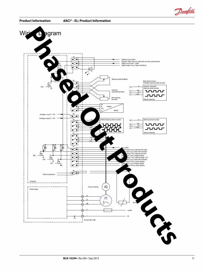
Wiring Diagram
IG
+Ubatt
0V-
+
W
V
U
X1
X5
X6
X3
1
1
1
1
1
1
3
3
PA1
PA2
PA3
X8
X9
1
+15V
0V
A
B
+5V
0V
A
#A
#B
B
1
X7
+15VB
0V
AX6.3
X6.2X6.5X6.1
X3.1 +15VB
0V
AX3.2
X3.3X2.2
X2
5
3
PA4
A15VB0V
RS485
RS232
Power stage
Controller
Digital input 4 (e.g. dead man's handle)
Digital input 2 (e.g. dead man's handle)Digital input 5-6 (e.g. travel signals)
Digital input 5-6 (e.g. travel signals)
Key switch
RS422 steering wheel encoder
Steering angle feedback
Tiller steeringset value
Digital output 1 (e.g. steering angle > X°)
Screws M5 or M8
Analogue output 0...10V
Analogue input 0...10V
Motor temperature
(optionaldual potentiometer)
Alternative Function :redundant steering wheel encoder
Sensor bearing
Steering wheel encoder
(Sensor bearing)
optional: redundant steering wheel encoder
(Sensor bearing)
Digital input 1 (e.g. straight ahead)
Digital input 3 (e.g. straight ahead)Digital output 2 (e.g. steering limit left)
Digital output 3 (e.g. steering limit right)
Safetey circuit output
Safety circuit input +UbattDigital output 4 (e.g. Status indication)
Termistor
Optional: Slider input for redundant set value potentiometer
Phased Out Products

Product Information dACi® - EL: Product Information
BLN-10294 • Rev BA • Sep 201312
DimensionsSize E1
X1
X2
X5
X6
X3
+ U V W -
140,0
128,0
148,0160,0
ø 6,0
60,0
X9
X8
X7
Phased Out Products
Product Information dACi® - EL: Product Information
BLN-10294 • Rev BA • Sep 2013 13
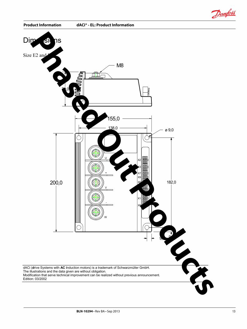
Dimensions
Size E2 and E3:
U
+
V
-
W
200,0
M8
9,5 9,0
182,0
ø 9,0
70,0
X1
X2
X5
X6
X3
X9
X8
X7
138,0
155,0
dACi (drive Systems with AC induction motors) is a trademark of Schwarzmüller GmbH.The illustrations and the data given are without obligation.Modification that serve technical improvement can be realized without previous announcement.Edition: 03/2002
Phased Out Products

Product Information dACi® - EL: Product Information
BLN-10294 • Rev BA • Sep 201314
Series D
dACi - TAAC-Controller for
Traction Drive Units
Phased Out Products

Product Information dACi® - EL: Product Information
BLN-10294 • Rev BA • Sep 2013 15
dACi Series D ...
... is an AC-controller, optimized for batterypowered material handling vehicles of the mediumand high power range, like counterbalance trucks,reach trucks and high level order pickers.
The electronic consists of a three-phase inverterand a control unit.AC- technology offers the following advantagesin comparison to DC- technology:
♦ Maintenance-free operation
no mechanical wear and tear on the motor
no mechanical switch contacts (contactors)fordirection reversal or recuperation
♦ Recuperation
without any additional components
♦ Higher efficiency
♦ More flexibility in construction
less wiring
the motor does not need to be openlyaccessible, because it operatesmaintenance-free
♦ Explosion protection
easy realizable due to no sparking in themotor
Features
♦ Proportional drive reaction
vehicle speed is directly dependant uponthe position of the acceleration pedal(speed control)
stalled torque
sensitive driving over bumps and on ramps
no unintentional acceleration while drivingdown steep grades
♦ Individual possibilities ofadjustment
acceleration pedal sensitivity
max. acceleration
max. deceleration
adjustable drive curve generator
♦ Special fork lift truck functions
seat switch surveillance
creeping speed
driver output for main-contactor withvoltage-reduction
driver output for magnetic brake
all inverse diodes for external componentsalready mounted on-board
♦ Special Version for dual-driveapplication available
Communication between the two drive-controllers via CAN-Bus.
Torque-allocation-controller, to perform bestfeed with lowest energy.
Phased Out Products

Product Information dACi® - EL: Product Information
BLN-10294 • Rev BA • Sep 201316
Principle Diagram:
SI: Selectable Input
SafetyApart from its maintenance-free operation, an AC-induction motor also offers additional safety. An error inthe power stage or in the motor always reduces the torque and never can produce an unintentionalmaximum torque like it could with a DC drive.
Furthermore dACi possesses various safety equipments and also meets the requirements of theEN 11 75-1 and DIN EN 954-1 standards.
forwardbackward
seat switchbrake-pedal
SI 1SI 2SI 3SI 4
keyswitch
V
dACi-TA
TractionDrive
3~
ϑ
brake
RS485 / CAN
set value
Phased Out Products

Product Information dACi® - EL: Product Information
BLN-10294 • Rev BA • Sep 2013 17
Features:• operating modes:
− open loop speed control(no incremental encoder necessary)
− closed loop speed control(incremental encoder necessary)
− torque control (incremental encodernecessary)
• adjustable set value curve (e.g. characteristicof acceleration pedal)
• 2 analogue inputs, usable as− potentiometer input (with fault detection)− voltage input 0...+10V
• adjustable travel characteristics− adjustable drive curve generator− maximum speed forward− maximum speed backward− max. acceleration− deceleration when reducing the set value− deceleration when activating an opposite
travel direction(adjustable continuously with the set valueinput)
− deceleration when brake pedal is activated(digital input)
− deceleration when activating creepingspeed (e.g. while making turns)
• 3 creeping speeds
• 2 modes for the travel signals− direction forward; direction backward− enable; direction
• different modes of stopping− turn off motor and roll until standstill− turn off motor and close magnetic brake− stop by leading
• seat switch surveillance− adjustable time delay
• integrated fuse for control-lines
• integrated fuse for power-line
• driver output for main-contactor with voltage-reduction
• magnetic brake driver-output− short-circuit protected output− adjustable delay time
• key switch input
• fault detection of incremental encoder for− cable breakage− shorted circuits
• fault detection of the potentiometers for:− cable breakage− shorted circuits
• battery voltage monitoring− adjustable minimum- and maximum voltage
limits
• motor temperature monitoring with faultdetection of the temperature sensor for cablebreakage and shorted circuits
• power stage temperature monitoring with faultdetection of the temperature sensor for cablebreakage and shorted circuits
• operation signal (LED)
• 6 digital inputs, selectable for− creep speed− seat switch− brake pedal switch− enable− custom specific function
• 2 digital outputs, selectable for− ready-signal− active brake− chosen direction− torque > threshold value (adjustable)− status signal− high temperature warning of the power
stage− high temperature warning of the motor
• 4 digital driver-outputs to switch hydraulicvalves or contactors
• analogue output, selectable for− speed set value− speed actual value− speed deviation− torque− motor frequency− fixed value
• serial interface RS485 or CAN, each with abusmastering record
• all functions can also be performed via serialinterface (RS485 or CAN)
• possibilities of parameter settings:− PC software under MS-Windows− BPK: handheld console
Phased Out Products

Product Information dACi® - EL: Product Information
BLN-10294 • Rev BA • Sep 201318
Technical dataPower dataType:dACi-TA
24/480GD
24/600GD
24/720GD
36/400GD
36/500GD
36/600GD
Size D8 D10 D12 D8 D10 D12Nominal battery voltage [V] 24 36Input voltage range [V]continuousmaximum (<30s)
17...3017...35
25...4525...50
Nominal current [A] 1) 240 300 360 200 250 300Maximum current [A] 2) 480 600 720 400 500 600Output voltage [V] 3) 3x 0...16 3 x 0 ... 24Dimensions [mm]W x H x D
220 x230 x 95
220 x330 x 95
220 x230 x 95
220 x330 x 95
Power connectors(screw terminals)
M8 M10 M10 M8 M10 M10
Type:dACi-TA
48/300GD
48/375GD
48/450GD
48/600GD
48/750GD
Size D8 D10 D12 D16 D20Nominal battery voltage [V] 48Input voltage range [V]continuousmaximum (<30s)
30...6030...70
Nominal current [A] 1) 150 190 225 300 375Maximum current [A] 2) 300 375 450 600 750Output voltage [V] 3) 3 x 0 ... 32Dimensions [mm]W x H x D
220 x230 x 95
220 x330 x 95
220 x430x100
Power connectors(screw terminals)
M8 M8 M8 M10 M10
Type:dACi-TA
80/160GD
80/200GD
80/240GD
80/320GD
80/400GD
80/480GD
80/600GD
Size D8 D10 D12 D16k D20 D24k D24kNominal battery voltage [V] 80Input voltage range [V]continuousmaximum (<30s)
48...10048...115
Nominal current [A] 1) 80 100 120 160 200 240 300Maximum current [A] 2) 160 200 240 320 400 480 600Output voltage [V] 3) 3 x 0 ... 53Dimensions [mm]W x H x D
220 x230 x 95
220 x330 x 95
220 x330x100
220 x430x100
220 x430x100
Power connectors(screw terminals)
M8 M8 M8 M10 M10 M10 M10
1) dependant on the temperature resistance of the mounting plate2) duration depends on the temperature resistance of the mounting plate3) at input voltage = nominal battery voltage
Phased Out Products

Product Information dACi® - EL: Product Information
BLN-10294 • Rev BA • Sep 2013 19
InterfacesType: dACi-TA 24/xxx GD 36/xxx GD
48/xxx GD80/xxx GD
8 Digital Inputs (X6.2, .3, .4, .5, .7, .8, .9, .10)Logic high-aktivInput resistance [Ω] 3,5k 10k 25kLow-level [V] max 2 3 8High-level [V] min 12 24 48
2 Analogue Inputs (X6.6, X5.7)Resolution 10 bitInput resistance [Ω] 94kSelected as potentiometer input
Voltage range [V] 2...8Resistance of the ext. potentiometer [Ω] 5k
Selected as voltage inputVoltage range [V] 0...10
Digital OutputsMain Contactor driver-output (X2.2) low-side-switch with inverse diode
Nominal current [A] 2,0 1,0 1,0Maximum current [A] 3,0 1,5 1,5Signal-condition 1s 100% on-period, then 60% on-period
Magnetic Brake driver-output (X4.5) low-side-switch with inverse diodeNominal current [A] 2,0 1,0 1,0Maximum current [A] 3,0 1,5 1,5Signal-condition 1s 100% on-period, then 60% on-period
Programmable Outputs 1 u. 2 (X1.3, .6) low-side-switch with inverse diodeNominal current [A] 1,0 0,7 0,3Maximum current [A] 1,5 1,0 0,5
Programmable Outputs 3 u. 4 * (X3.6, .7) low-side-switch with inverse diodeNominal current [A] 2,0 1,0 1,0Maximum current [A] 3,0 1,5 1,5
Programmable Outputs 5 u. 6 * (X3.3-8, X3.4-9) high-side-switch with inverse diodeNominal current [A] 3,0 2,0 0,7Maximum current [A] 4,5 3,0 1,0
Analogue Output (X1.2-5)Voltage range [V] 0...10Output resistance [Ω] 100
Incremental encoder 1 (X4.3, .4, .7, .8)Level [V] 0 / 15 A,B (e.g. sensor bearing)Supply 15V, max 100mA
Incremental encoder 2 * (X8)Level [V] 0 / 5 A, #A, B, #B (RS422)Supply 5V, max 100mA
Motor temperature sensor (X4.2-6)Type PTC
Serial interfaceRS485 (X7)
Supply for ext. Converter 15V, max 100mACAN * (X9) V2.0A (V2.0B passive)
connectable terminal resistor 120 Ω
Phased Out Products

Product Information dACi® - EL: Product Information
BLN-10294 • Rev BA • Sep 201320
OthersSwitching frequency 16kHz standard; adjustable 4, 8, 12, 16, 20 kHzEfficiency about 95% at nominal outputOutput frequency 0...300 HzTemperature range -40°C ... 50°C (mounting plate)Relative humidity max. 90%, no condensationOperation signal built-in LEDSignal line connectors Molex mini-fit juniorIP protection IP40, IP54 optional
* optional
InterfacesType: dACi-TA 24/xxx GD 36/xxx GD
48/xxx GD80/xxx GD
8 Digital Inputs (X6.2, .3, .4, .5, .7, .8, .9, .10)Logic high-aktivInput resistance [Ω] 3,5k 10k 25kLow-level [V] max 2 3 8High-level [V] min 12 24 48
2 Analogue Inputs (X6.6, X5.7)Resolution 10 bitInput resistance [Ω] 94kSelected as potentiometer input
Voltage range [V] 2...8Resistance of the ext. potentiometer [Ω] 5k
Selected as voltage inputVoltage range [V] 0...10
Digital OutputsMain Contactor driver-output (X2.2) low-side-switch with inverse diode
Nominal current [A] 2,0 1,0 1,0Maximum current [A] 3,0 1,5 1,5Signal-condition 1s 100% on-period, then 60% on-period
Magnetic Brake driver-output (X4.5) low-side-switch with inverse diodeNominal current [A] 2,0 1,0 1,0Maximum current [A] 3,0 1,5 1,5Signal-condition 1s 100% on-period, then 60% on-period
Programmable Outputs 1 u. 2 (X1.3, .6) low-side-switch with inverse diodeNominal current [A] 1,0 0,7 0,3Maximum current [A] 1,5 1,0 0,5
Programmable Outputs 3 u. 4 * (X3.6, .7) low-side-switch with inverse diodeNominal current [A] 2,0 1,0 1,0Maximum current [A] 3,0 1,5 1,5
Programmable Outputs 5 u. 6 * (X3.3-8, X3.4-9) high-side-switch with inverse diodeNominal current [A] 3,0 2,0 0,7Maximum current [A] 4,5 3,0 1,0
Analogue Output (X1.2-5)Voltage range [V] 0...10Output resistance [Ω] 100
Incremental encoder 1 (X4.3, .4, .7, .8)Level [V] 0 / 15 A,B (e.g. sensor bearing)Supply 15V, max 100mA
Incremental encoder 2 * (X8)Level [V] 0 / 5 A, #A, B, #B (RS422)Supply 5V, max 100mA
Motor temperature sensor (X4.2-6)Type PTC
Serial interfaceRS485 (X7)
Supply for ext. Converter 15V, max 100mACAN * (X9) V2.0A (V2.0B passive)
connectable terminal resistor 120 Ω
Phased Out Products

Product Information dACi® - EL: Product Information
BLN-10294 • Rev BA • Sep 2013 21
Wiring Diagram
B0VA+15V
V-+
RS232
RS4850VB15VA
+
+
+
+
+
-
+
+
-
-
+
-
-
-
-
-
+U batt
0V
+-
UVW
1
4
3
2X7
1
3 X1
4
6
X21 2
X66
1 7
12
X54
1 5
8
X3 *
1 6
X44
1 5
8
+24V
+15V+15V
+5V
+5V0V
X8 *
1
3 6
4
5V#A0VBA#B
+24V
X9 *
CAN_L
RR
+24V
CAN_L
0V
CAN_H
CAN_H
120 Ohm
5
84
1
1 Ohm
105
PA_3
PA_4
PA_5
PA_6
PA_1
PA_2
PE_3
PE_4
PE_5
PE_6
PE_2
PE_1
FR_1
FR_2
PC
Analogue output 0...10V
Key switch
Main contactor
Sensor-bearing
Thermistor
Brake
Set value 2
Set value 1
PE_2 (e.g. creep speed 2)PE_6 (e.g. seat switch)PE_1 (e.g. creep speed 1)PE_5 (e.g. brake pedal switch)FR_2 (Backwards)PE_4 FR_1 (Forwards)PE_3 (e.g. creep speed 3)
Incr.encoder
RS422
Main contactor
* optional
Con
trolle
r
Supp
ly u
nit
Power stage
Phased Out Products

Product Information dACi® - EL: Product Information
BLN-10294 • Rev BA • Sep 201322
Dimensions
Size L1 L2 HD08 230 mm 212 mm 95 mmD12 330 mm 312 mm 95 mmD16k 330 mm 312 mm 100 mmD16 430 mm 412 mm 100 mmD24k 430 mm 412 mm 100 mm
dACi (drive Systems with AC induction motors) is a trademark of Schwarzmüller GmbH.The illustrations and the data given are without obligation.Modification that serve technical improvement can be realized without previous announcement.Edition: 03/2002
220,0
M8 / M10
H
+
X1 X2 X3 X4 X5 X6 X7 X8 X9
L1L2
205,0 ø 9,0
-
U
V
W
+
Phased Out Products

Product Information dACi® - EL: Product Information
BLN-10294 • Rev BA • Sep 2013 23
Series D
dACi - HAC-Controller for
Hydraulic Pump Drives
Phased Out Products

Product Information dACi® - EL: Product Information
BLN-10294 • Rev BA • Sep 201324
dACi-H...
...is an AC-Controller for hydraulic pump driveswith AC-induction motor.
The electronic consists of a three-phase inverterand a control unit.AC- technology offers the following advantagesin comparison to DC- technology:
♦ Maintenance-free operation
no mechanical wear and tear on the motor
no mechanical switch contacts (contactor)
♦ Recuperation
without any additional components
♦ Higher efficiency
♦ More flexibility in construction
less wiring
the motor does not need to be openlyaccessible because it operatesmaintenance-free
♦ Explosion protection
easy realizable due to no sparking in themotor
Features:♦ Open loop mode
no incremental encoder necessary
current limiting
♦ Closed loop mode
constant speed, independent on load
adjustable torque limit
♦ Different set value inputs
analogue-input for continuous set value
digital-inputs for selection of fixed setvalues
Phased Out Products

Product Information dACi® - EL: Product Information
BLN-10294 • Rev BA • Sep 2013 25
Principle Diagram
SI: Selectable Input
SafetyApart from its maintenance-free operation, an AC-induction motor also offers additional safety. An error in the power stage or in the motor always reduces the torque and never can produce an unintentional maximum torquelike it could with a DC drive.
Furthermore dACi possesses various safety equipments and also meets the requirements of theEN 11 75-1 and DIN EN 954-1 standards.
direction 1
direction 2
speed 1
speed 2
speed 3
speed 4
speed 5
SI
keyswitch
V
dACi-H
Drive forHydraulicPumps
RS485 / CAN
ϑ
3~
set value
Phased Out Products

Product Information dACi® - EL: Product Information
BLN-10294 • Rev BA • Sep 201326
Features:
• operating modes:− open loop speed control
(no incremental encoder necessary)− closed loop speed control
(incremental encoder necessary)
• adjustable set value curve
• 2 analogue inputs, usable as− potentiometer input− voltage input 0...+10V
• adjustable speed process− maximum speed for counterclockwise
rotation− maximum speed for clockwise rotation− acceleration− deceleration
• 5 fixed set values for speed (activated bydigital inputs)
• 2 modes for control signals:− start counterclockwise operation; start
clockwise operation− enable; direction of rotation
• different stopping modes:− turn off motor− stop by leading
• key switch input
• integrated fuse for control-lines
• integrated fuse for power line
• driver-output for main-contactor with voltage-reduction
• fault detection of the incremental encoder for:− cable breakage− shorted circuits
• fault detection of the potentiometers for:− cable breakage− shorted circuits
• battery voltage monitoring− adjustable minimum- and maximum voltage
limits
• motor temperature monitoring with faultdetection of the temperature sensor for cablebreakage and shorted circuits
• power stage temperature monitoring with faultdetection of the temperature sensor for cablebreakage and shorted circuits
• current limiter
• operation signal (LED)
• 6 digital inputs, selectable for− fixed speed set values− enable− custom specific function
• 2 digital outputs, selectable for− ready-signal− active drive− torque > threshold value (adjustable)− status signal− high temperature warning of the power
stage− high temperature warning of the motor
• 4 digital driver-outputs to switch hydraulicvalves or contactors
• analogue output, selectable for− speed set value− speed actual value− speed deviation− torque− motor frequency− fixed value
• serial interface RS485 or CAN, each with abusmastering record
• all functions can also be performed via a serialinterface
• parameter setting possibilities:− PC software under MS-Windows− BPK: handheld console
Phased Out Products

Product Information dACi® - EL: Product Information
BLN-10294 • Rev BA • Sep 2013 27
Technical dataPower dataType:dACi-H
24/480GD
24/600GD
24/720GD
36/400GD
36/500GD
36/600GD
Size D8 D10 D12 D8 D10 D12Nominal battery voltage [V] 24 36Input voltage range [V]continuousmaximum (<30s)
17...3017...35
25...4525...50
Nominal current [A] 1) 240 300 360 200 250 300Maximum current [A] 2) 480 600 720 400 500 600Output voltage [V] 3) 3x 0...16 3 x 0 ... 24Dimensions [mm]W x H x D
220 x230 x 95
220 x330 x 95
220 x230 x 95
220 x330 x 95
Power connectors(screw terminals)
M8 M10 M10 M8 M10 M10
Type:dACi-H
48/300GD
48/375GD
48/450GD
48/600GD
48/750GD
Size D8 D10 D12 D16 D20Nominal battery voltage [V] 48Input voltage range [V]continuousmaximum (<30s)
30...6030...70
Nominal current [A] 1) 150 190 225 300 375Maximum current [A] 2) 300 375 450 600 750Output voltage [V] 3) 3 x 0 ... 32Dimensions [mm]W x H x D
220 x230 x 95
220 x330 x 95
220 x430x100
Power connectors(screw terminals)
M8 M8 M8 M10 M10
Type:dACi-H
80/160GD
80/200GD
80/240GD
80/320GD
80/400GD
80/480GD
80/600GD
Size D8 D10 D12 D16k D20 D24k D24kNominal battery voltage [V] 80Input voltage range [V]continuousmaximum (<30s)
48...10048...115
Nominal current [A] 1) 80 100 120 160 200 240 300Maximum current [A] 2) 160 200 240 320 400 480 600Output voltage [V] 3) 3 x 0 ... 53Dimensions [mm]W x H x D
220 x230 x 95
220 x330 x 95
220 x330x100
220 x430x100
220 x430x100
Power connectors(screw terminals)
M8 M8 M8 M10 M10 M10 M10
1) dependant on the temperature resistance of the mounting plate2) duration depends on the temperature resistance of the mounting plate3) at input voltage = nominal battery voltage
Phased Out Products

Product Information dACi® - EL: Product Information
BLN-10294 • Rev BA • Sep 201328
InterfacesType: dACi-H 24/xxx GD 36/xxx GD
48/xxx GD80/xxx GD
8 Digital Inputs (X6.2, .3, .4, .5, .7, .8, .9, .10)Logic high-aktivInput resistance [Ω] 3,5k 10k 25kLow-level [V] max 2 3 8High-level [V] min 12 24 48
2 Analogue Inputs (X6.6, X5.7)Resolution 10 bitInput resistance [Ω] 94kSelected as potentiometer input
Voltage range [V] 2...8Resistance of the ext. potentiometer [Ω] 5k
Selected as voltage inputVoltage range [V] 0...10
Digital OutputsMain Contactor driver-output (X2.2) low-side-switch with inverse diode
Nominal current [A] 2,0 1,0 1,0Maximum current [A] 3,0 1,5 1,5Signal-condition 1s 100% on-period, then 60% on-period
Magnetic Brake driver-output (X4.5) low-side-switch with inverse diodeNominal current [A] 2,0 1,0 1,0Maximum current [A] 3,0 1,5 1,5Signal-condition 1s 100% on-period, then 60% on-period
Programmable Outputs 1 u. 2 (X1.3, .6) low-side-switch with inverse diodeNominal current [A] 1,0 0,7 0,3Maximum current [A] 1,5 1,0 0,5
Programmable Outputs 3 u. 4 * (X3.6, .7) low-side-switch with inverse diodeNominal current [A] 2,0 1,0 1,0Maximum current [A] 3,0 1,5 1,5
Programmable Outputs 5 u. 6 * (X3.3-8, X3.4-9) high-side-switch with inverse diodeNominal current [A] 3,0 2,0 0,7Maximum current [A] 4,5 3,0 1,0
Analogue Output (X1.2-5)Voltage range [V] 0...10Output resistance [Ω] 100
Incremental encoder 1 (X4.3, .4, .7, .8)Level [V] 0 / 15 A,B (e.g. sensor bearing)Supply 15V, max 100mA
Incremental encoder 2 * (X8)Level [V] 0 / 5 A, #A, B, #B (RS422)Supply 5V, max 100mA
Motor temperature sensor (X4.2-6)Type PTC
Serial interfaceRS485 (X7)
Supply for ext. Converter 15V, max 100mACAN * (X9) V2.0A (V2.0B passive)
connectable terminal resistor 120 Ω
Phased Out Products

Product Information dACi® - EL: Product Information
BLN-10294 • Rev BA • Sep 2013 29
OthersSwitching frequency 16kHz standard; adjustable 4, 8, 12, 16, 20 kHzEfficiency about 95% at nominal outputOutput frequency 0...300 HzTemperature range -40°C ... 50°C (mounting plate)Relative humidity max. 90%, no condensationOperation signal built-in LEDSignal line connectors Molex mini-fit juniorIP protection IP40, IP54 optional
* optional
InterfacesType: dACi-H 24/xxx GD 36/xxx GD
48/xxx GD80/xxx GD
8 Digital Inputs (X6.2, .3, .4, .5, .7, .8, .9, .10)Logic high-aktivInput resistance [Ω] 3,5k 10k 25kLow-level [V] max 2 3 8High-level [V] min 12 24 48
2 Analogue Inputs (X6.6, X5.7)Resolution 10 bitInput resistance [Ω] 94kSelected as potentiometer input
Voltage range [V] 2...8Resistance of the ext. potentiometer [Ω] 5k
Selected as voltage inputVoltage range [V] 0...10
Digital OutputsMain Contactor driver-output (X2.2) low-side-switch with inverse diode
Nominal current [A] 2,0 1,0 1,0Maximum current [A] 3,0 1,5 1,5Signal-condition 1s 100% on-period, then 60% on-period
Magnetic Brake driver-output (X4.5) low-side-switch with inverse diodeNominal current [A] 2,0 1,0 1,0Maximum current [A] 3,0 1,5 1,5Signal-condition 1s 100% on-period, then 60% on-period
Programmable Outputs 1 u. 2 (X1.3, .6) low-side-switch with inverse diodeNominal current [A] 1,0 0,7 0,3Maximum current [A] 1,5 1,0 0,5
Programmable Outputs 3 u. 4 * (X3.6, .7) low-side-switch with inverse diodeNominal current [A] 2,0 1,0 1,0Maximum current [A] 3,0 1,5 1,5
Programmable Outputs 5 u. 6 * (X3.3-8, X3.4-9) high-side-switch with inverse diodeNominal current [A] 3,0 2,0 0,7Maximum current [A] 4,5 3,0 1,0
Analogue Output (X1.2-5)Voltage range [V] 0...10Output resistance [Ω] 100
Incremental encoder 1 (X4.3, .4, .7, .8)Level [V] 0 / 15 A,B (e.g. sensor bearing)Supply 15V, max 100mA
Incremental encoder 2 * (X8)Level [V] 0 / 5 A, #A, B, #B (RS422)Supply 5V, max 100mA
Motor temperature sensor (X4.2-6)Type PTC
Serial interfaceRS485 (X7)
Supply for ext. Converter 15V, max 100mACAN * (X9) V2.0A (V2.0B passive)
connectable terminal resistor 120 Ω
Phased Out Products
Product Information dACi® - EL: Product Information
BLN-10294 • Rev BA • Sep 201330
Wiring Diagram
B0VA+15V
V-+
RS232
RS4850VB15VA
+
+
+
+
+
-
+
+
-
-
+
-
-
-
-
-
+U batt
0V
+-
UVW
1
4
3
2X7
1
3 X1
4
6
X21 2
X66
1 7
12
X54
1 5
8
X3 *
1 6
X44
1 5
8
+24V
+15V+15V
+5V
+5V0V
X8 *
1
3 6
4
5V#A0VBA#B
+24V
X9 *
CAN_L
RR
+24V
CAN_L
0V
CAN_H
CAN_H
120 Ohm
5
84
1
1 Ohm
105
PA_3
PA_4
PA_5
PA_6
PA_1
PA_2
PE_3
PE_4
PE_5
PE_6
PE_2
PE_1
FR_1
FR_2
PC
Analogue output 0...10V
Key switch
Main contactor
Sensor-bearing
Thermistor
Brake
Set value 2
Set value 1
PE_2 (e.g. fixed speed 2)PE_6 (e.g. fixed speed 4)PE_1 (e.g. fixed speed 1)PE_5FR_2 (counterclockwise)PE_4 FR_1 (clockwise)PE_3 (e.g. fixed speed 3)
Incr.encoder
RS422
Main contactor
* optional
Con
trolle
r
Supp
ly u
nit
Power stage
Phased Out Products

Product Information dACi® - EL: Product Information
BLN-10294 • Rev BA • Sep 2013 31
Dimensions
Size L1 L2 HD08 230 mm 212 mm 95 mmD12 330 mm 312 mm 95 mmD16k 330 mm 312 mm 100 mmD16 430 mm 412 mm 100 mmD24k 430 mm 412 mm 100 mm
dACi (drive Systems with AC induction motors) is a trademark of Schwarzmüller GmbH.The illustrations and the data given are without obligation.Modification that serve technical improvement can be realized without previous announcement.Edition: 03/2002
220,0
M8 / M10
H
+
X1 X2 X3 X4 X5 X6 X7 X8 X9
L1L2
205,0 ø 9,0
-
U
V
W
+
Phased Out Products

Product Information dACi® - EL: Product Information
BLN-10294 • Rev BA • Sep 201332
Series C
The 2nd Generation
Phased Out Products

Product Information dACi® - EL: Product Information
BLN-10294 • Rev BA • Sep 2013 33
dACi series C ...
... is an AC-controller, optimized for batterypowered material handling vehicles of thesmall and medium power range, likepedestrian trucks, order-pickers and small lifttrucks.
The electronic consists of a three-phase inverterand a control unit. Besides the well knownfeatures of Series A, the Series C includes driversfor direct connection of contactors and valves.
AC- technology offers the following advantagesin comparison to DC- technology:
♦ Maintenance-free operation
no mechanical wear and tear on the motor
no mechanical switch contacts (contactors)fordirection reversal or recuperation.
♦ Recuperation
without any additional components
♦ Higher efficiency
♦ More flexibility in construction
less wiring
the motor does not need to be openlyaccessible, because it operatesmaintenance-free
♦ Explosion protection easy realizable due to no sparking in themotor
Features:
♦ Proportional drive reaction
vehicle speed is directly dependant uponthe position of the acceleration pedal(speed control)
stalled torque
sensitive driving over bumps and on ramps
no unintentional acceleration while drivingdown steep grades
♦ Individual possibilities of adjustment
acceleration pedal sensitivity
max. acceleration
max. deceleration
adjustable drive curve generator
♦ Special functions for pedestrian trucks(walkies)
emergency reverse switch (belly switch)
tiller joint switch
set value input:potentiometer or 3-step-switch
driver output for main-contactor withvoltage-reduction
hydraulic-unit (optional) with- potentiometer input- 3 switch inputs- 2 outputs for proportional control valves- 3 outputs for on/off valves- output for universal contactor
(e.g. for DC-pump-motor)
no external wiring necessary
all inverse diodes for external componentsalready mounted on-board
Phased Out Products

Product Information dACi® - EL: Product Information
BLN-10294 • Rev BA • Sep 201334
Principle diagram:
SI: Selectable Input
SafetyApart from its maintenance-free operation, an AC-induction motor also offers additional safety. Anerror in the power stage or in the motor always reduces the torque and never can produce anunintentional maximum torque like it could with a DC drive.
Furthermore dACi possesses various safety equipments and also meets the requirements of theEN 11 75-1 and DIN EN 954-1 standards.
forwardbackward
seat switchbrake-pedal
SI 1 SI 2SI 3SI 4
key-switch
set value
SI 5SI 6
main contactor
V
dACi-TA
Series C
OptionHydraulic-
Unit
3~
ϑ
brake
RS485 / CAN
set value
proportional valves
Contactor
on/off valves
Phased Out Products

Product Information dACi® - EL: Product Information
BLN-10294 • Rev BA • Sep 2013 35
Features• operating modes:
− open loop speed control(no incremental encoder necessary)
− closed loop speed control(incremental encoder required)
• adjustable set value curve
• different set value inputs− potentiometer (with fault detection)− voltage input 0...+10V− 3-step-switch
• adjustable travel characteristics− adjustable drive curve generator− maximum speed forward− maximum speed backward− max. acceleration− deceleration when reducing the set value− deceleration when activating an opposite
travel direction(adjustable continuously with the set valueinput)
• 3 creeping speeds
• different stopping modes− turn off motor and roll until standstill− turn off motor and close magnetic brake− stop by leading
• key switch input
• integrated fuse for control-lines
• seat switch surveillance− adjustable time delay
• driver output for main-contactor with voltage-reduction− short-circuit protected output− adjustable delay time
• magnetic brake driver output with voltage-reduction− short-circuit protected output− adjustable delay time
• battery voltage monitoring− adjustable minimum- and maximum voltage
limits
• fault detection of the potentiometers for− cable breakage− shorted circuits
• motor temperature monitoring
• power stage temperature monitoring
• special functions for pedestrian trucks(walkies)− emergency reverse switch surveillance− tiller joint switch surveillance
• integrated hydraulic unit− control unit for proportional control valves input for set value potentiometer input for potentiometer zero switch 2 outputs for proportional control valves
− control unit for directional control valves 2 switch inputs 3 outputs for on/off valves
− driver for universal contactor(e.g. for DC-pump motor)
• operation signal (LED)
• 8 digital inputs, selectable for− forward− backward− creep speed− seat switch− brake pedal switch− emergency reverse switch− tiller joint switch− enable
• 2 digital outputs, selectable for− ready-signal− error code− power stage enabled− torque > threshold value (adjustable)− high temperature warning of the power
stage− high temperature warning of the motor
• analogue output, selectable for− speed set value− speed actual value− speed deviation− torque− motor frequency− fixed value
• all functions can also be performed via serialinterface (RS485 or CAN)
• possibilities of parameter setting:− PC software under MS-Windows− BPK: handheld console
Phased Out Products

Product Information dACi® - EL: Product Information
BLN-10294 • Rev BA • Sep 201336
Technical dataPower dataType: dACi-TA 24/xxx GC 24/120 24/180 24/240 24/360 24/480Size C2 C3 C4 C6 C8kNominal battery voltage [V] 24Input voltage range [V] permanent: 17…30; short-time: 17…35 (30s)Nominal current [A] 1) 60 90 120 180 240Maximum current [A]2) 120 180 240 360 480Output voltage [V]3) 3 x 0 ... 16Dimensions [mm] (w x h x d) 155 x 200 x 70 155 x 300 x 80power connectors screw terminals M8 screw terminals M10
Type: dACi-TA 36/xxx GC 36/100 36/150 36/300 36/400Size C2 C3 C6 C8kNominal battery voltage [V] 36Input voltage range [V] permanent: 25…45; short-time:25…50 (30s)Nominal current [A] 1) 50 75 150 200Maximum current [A]2) 100 150 300 400Output voltage [V]3) 3 x 0 ... 24Dimensions [mm] (w x h x d) 155 x 200 x 70 155 x 300 x 80power connectors screw terminals M8 screw terminals M10
Type: dACi-TA 48/xxx GC 48/075 48/112 48/225 48/300Size C2 C3 C6 C8kNominal battery voltage [V] 48Input voltage range [V] permanent: 30…60; short-time: 30…70 (30s)Nominal current [A] 1) 37 56 112 150Maximum current [A]2) 75 112 225 300Output voltage [V]3) 3 x 0 ... 32Dimensions [mm] (w x h x d) 155 x 200 x 70 155 x 300 x 80power connectors screw terminals M8 screw terminals M10
Type: dACi-TA 80/xxx GC 80/040 80/060 80/120 80/160Size C2 C3 C6 C8kNominal battery voltage [V] 80Input voltage range [V] permanent: 48…100; short-time: 48…115 (30s)Nominal current [A] 1) 20 30 60 80Maximum current [A]2) 40 60 120 160Output voltage [V]3) 3 x 0 ... 53Dimensions [mm] (w x h x d) 155 x 200 x 70 155 x 300 x 80power connectors screw terminals M8 screw terminals M101) dependant on the temperature resistance of the mounting plate2) duration depends on the temperature resistance of the mounting plate3) at input voltage = nominal battery voltage
OthersSwitching frequency 16kHz standard; adjustable 4, 8, 12, 16, 20 kHzEfficiency about 95% at nominal outputOutput frequency 0...300 HzTemperature range -40°C ... 50°C (mounting plate)Relative humidity max. 90%, no condensationOperation signal built-in LEDSignal line connectors Molex mini-fit juniorIP protection IP40, IP54 optional
Phased Out Products

Product Information dACi® - EL: Product Information
BLN-10294 • Rev BA • Sep 2013 37
Technical dataPower dataType: dACi-TA 24/xxx GC 24/120 24/180 24/240 24/360 24/480Size C2 C3 C4 C6 C8kNominal battery voltage [V] 24Input voltage range [V] permanent: 17…30; short-time: 17…35 (30s)Nominal current [A] 1) 60 90 120 180 240Maximum current [A]2) 120 180 240 360 480Output voltage [V]3) 3 x 0 ... 16Dimensions [mm] (w x h x d) 155 x 200 x 70 155 x 300 x 80power connectors screw terminals M8 screw terminals M10
Type: dACi-TA 36/xxx GC 36/100 36/150 36/300 36/400Size C2 C3 C6 C8kNominal battery voltage [V] 36Input voltage range [V] permanent: 25…45; short-time:25…50 (30s)Nominal current [A] 1) 50 75 150 200Maximum current [A]2) 100 150 300 400Output voltage [V]3) 3 x 0 ... 24Dimensions [mm] (w x h x d) 155 x 200 x 70 155 x 300 x 80power connectors screw terminals M8 screw terminals M10
Type: dACi-TA 48/xxx GC 48/075 48/112 48/225 48/300Size C2 C3 C6 C8kNominal battery voltage [V] 48Input voltage range [V] permanent: 30…60; short-time: 30…70 (30s)Nominal current [A] 1) 37 56 112 150Maximum current [A]2) 75 112 225 300Output voltage [V]3) 3 x 0 ... 32Dimensions [mm] (w x h x d) 155 x 200 x 70 155 x 300 x 80power connectors screw terminals M8 screw terminals M10
Type: dACi-TA 80/xxx GC 80/040 80/060 80/120 80/160Size C2 C3 C6 C8kNominal battery voltage [V] 80Input voltage range [V] permanent: 48…100; short-time: 48…115 (30s)Nominal current [A] 1) 20 30 60 80Maximum current [A]2) 40 60 120 160Output voltage [V]3) 3 x 0 ... 53Dimensions [mm] (w x h x d) 155 x 200 x 70 155 x 300 x 80power connectors screw terminals M8 screw terminals M101) dependant on the temperature resistance of the mounting plate2) duration depends on the temperature resistance of the mounting plate3) at input voltage = nominal battery voltage
OthersSwitching frequency 16kHz standard; adjustable 4, 8, 12, 16, 20 kHzEfficiency about 95% at nominal outputOutput frequency 0...300 HzTemperature range -40°C ... 50°C (mounting plate)Relative humidity max. 90%, no condensationOperation signal built-in LEDSignal line connectors Molex mini-fit juniorIP protection IP40, IP54 optional
Phased Out Products

Product Information dACi® - EL: Product Information
BLN-10294 • Rev BA • Sep 201338
Standard VersionInterfacesType: dACi-TA 24/xxx GC
24/xxx GC-H36/xxx GC36/xxx GC-H48/xxx GC48/xxx GC-H
80/xxx GC80/xxx GC-H
8 Digital Inputs (X6.2, .3, .4, .5, .7, .8, .9, .10)Logic high-activeInput resistance [Ω] 3,5k 10k 25kLow-level [V] max 2 3 8High-level [V] min 12 24 48
Analogue Input (X6.6)Resolution 10 bitInput resistance [Ω] 86kSelected as potentiometer input
Voltage range [V] 2...8Resistance of ext. potentiometer [Ω] 5k
Selected as voltage inputVoltage range [V] 0...10
Digital OutputsMain Contactor driver-output (X2.2) low-side-switch with inverse diode
Nominal current [A] 2,0 1,0 1,0Maximum current [A] 3,0 1,5 1,5Signal-condition 1s 100% on-period, then 60% on-period
Magnetic Brake driver-output (X4.5) low-side-switch with inverse diodeNominal current [A] 2,0 1,0 1,0Maximum current [A] 3,0 1,5 1,5Signal-condition 1s 100% on-period, then 60% on-period
2 Programmable Outputs (X1.3 and X1.6) low-side-switches with inverse diodesNominal current [A] 1,0 0,7 0,3Maximum current [A] 1,5 1,0 0,5
Analogue Output (X1.2-5)Voltage range [V] 0...10Output resistance [Ω] 100
Incremental Encoder (X4.3, .4, .7, .8)Level [V] 0 / 15 A,B (e.g. sensor bearing)Supply 15V, max 100mA
Motor Temperature Sensor (X4.2-6)Type PTC
Serial Interface (X7)RS485Supply for ext. Converter 15V, max 100mA
Phased Out Products

Product Information dACi® - EL: Product Information
BLN-10294 • Rev BA • Sep 2013 39
Hydraulic unitOnly types: dACi-TA 24/xxx GC-H 36/xxx GC-H
48/xxx GC-H80/xxx GC-H
3 Digital Inputs (X5.2, .3, .6)Logic high-activeInput resistance [Ω] 3,5k 10k 25kLow-level [V] max 2 3 8High-level [V] min 12 24 48
1 Analogue Input (X5.4)Resolution 10 bitInput resistance [Ω] 86kSelected as potentiometer inputVoltage range [V] 2...8Resistance of the ext. potentiometer [Ω] 5kSelected as voltage inputVoltage range [V] 0...10
4 Digital Outputs for on/off Valves or contactors (X3.7, .8, .9, .10)
low-side-switches with inverse diodes
Nominal current [A] 2,0 1,0 1,0Maximum current [A] 3,0 1,5 1,5
2 Outputs for Proportional Valves(X3.5-11, .6-12)
high-side-switches with inverse diodescurrent controlled, superposed with dither-signal
Nominal current [A] 3,0 2,0 0,7Maximum current [A] 4,5 3,0 1,0
Remark: The two outputs for proportional valves can not work simultaneously.
Phased Out Products

Product Information dACi® - EL: Product Information
BLN-10294 • Rev BA • Sep 201340
CAN-Bus VersionInterfacesType: dACi-TA 24/xxx GC-C
24/xxx GC-HC36/xxx GC-C36/xxx GC-HC48/xxx GC-C48/xxx GC-HC
80/xxx GC-C80/xxx GC-HC
3 Digital Inputs (X6.3, .5, .6)Logic high-activeInput resistance [Ω] 4,2k 16k 30kLow-level [V] max 2 4 6High-level [V] min 12 24 40
Digital OutputsMain Contactor driver-output (X2.2) low-side-switch with inverse diode
Nominal current [A] 2,0 1,0 1,0Maximum current [A] 3,0 1,5 1,5Signal-condition 1s 100% on-period, then 60% on-period
Magnetic Brake driver-output (X4.5) low-side-switch with inverse diodeNominal current [A] 2,0 1,0 1,0Maximum current [A] 3,0 1,5 1,5Signal-condition 1s 100% on-period, then 60% on-period
2 Programmable Outputs (X1.3 and X1.6) low-side-switches with inverse diodesNominal current [A] 1,0 0,7 0,3Maximum current [A] 1,5 1,0 0,5
Analogue Output (X1.2-5)Voltage range [V] 0...10Output resistance [Ω] 100
Incremental Encoder (X4.3, .4, .7, .8)Level [V] 0 / 15 A,B (e.g. sensor bearing)Supply 15V, max 100mA
Motor Temperature Sensor (X4.2-6)Type PTC
Serial interface (X7)RS485
Supply for ext. Converter 15V, max 100mACAN (X5) V2.0A (V2.0B passive)connectable terminal resistor 120Ω
Hydraulic unitOnly types: dACi-TA 24/xxx GC-HC 36/xxx GC-HC
48/xxx GC-HC80/xxx GC-HC
4 Digital Outputs for on/off Valves or Contactors (X3.7, .8, .9, .10)
low-side-switches with inverse diodes
Nominal current [A] 2,0 1,0 1,0Maximum current [A] 3,0 1,5 1,5
2 Outputs for Proportional Valves(X3.5-11, .6-12)
high-side-switches with inverse diodescurrent controlled, superposed with dither-signal
Nominal current [A] 3,0 2,0 0,7Maximum current [A] 4,5 3,0 1,0
Remark: The two outputs for proportional valves can not work simultaneously.
Phased Out Products

Product Information dACi® - EL: Product Information
BLN-10294 • Rev BA • Sep 2013 41
Wiring Diagram, Standard Version
B0VA+15V
Sensor-bearing
V-+
RS232
RS4850VB15VA
+
+
+
+
+
+
+
+
+
+
-
-
-
-
-
-
-
-
-
-
Initial liftInitial lower
Set value lift/lower
Creep speed 2Safety circuitCreep speed 1Tiller joint switch
Belly buttonForwardsCreep speed 3
Set value driving speed
Key switch
Analogue output
Main contactor
Valve 3 orcontactor forDC pump motor
Valve 4
Valve 5
Valve 6
Prop.-valve 2
Prop.-valve 1
Brake
Thermistor
+24V
0V
Enable lift/lower
Main contactor
+
-
UVW
1
4
3
2X7
1
3 X1
4
6
X21 2
X66
1 7
12
X54
1 5
8
X36
1 7
12
X44
1 5
8
*
* Example forprogrammable inputs
Backwards
Power stage
Con
trolle
r
only
with
opt
ion
"H"
only
with
O
ptio
n "H
"
Phased Out Products

Product Information dACi® - EL: Product Information
BLN-10294 • Rev BA • Sep 201342
Wiring Diagram, CAN-Bus Version
1
4
3
2X7
1
3 X1
4
6
B0VA+15V
V-+
RS232
RS4850VB15VA
+
+
+
+
+
+
+
+
-
-
-
-
-
-
-
-
+24V
0VX2
1 2
X36
1 7
12
X44
1 5
8
+
-
UVW
+ 24V
10A
2,7 kOhm
PA2
PA1
X54
1 5
8
X6
1
3
4
6
+15V
+24V
Sensor-bearing
Key switch
Analogue output
Main contactor
Valve 3 or contactor for DC pump motor
Valve 4
Valve 5
Valve 6
Prop.-valve 2
Prop.-valve 1
Brake
Thermistor
hour meter (example)
EnableCreep speed 2Creep speed 1
Main contactor
Con
trolle
r
Sup
ply
unit
Power stage
only
with
opt
ion
"H"
+24V0VCAN_LCAN_HCAN_LCAN_HRR
Phased Out Products

Product Information dACi® - EL: Product Information
BLN-10294 • Rev BA • Sep 2013 43
70,0
M8 / M10
H
X1
X3
X2
X4
X5
X6
X7
F
155,0
138,0
L2 L1
ø 9mm
+
V
-
W
U
Dimensions
Size L1 L2 H Screw terminalsC2, C3, C4 200 mm 182 mm 70 mm M8
C6, C8k 300 mm 282 mm 80 mm M10
dACi (drive Systems with AC induction motors) is a trademark of Schwarzmüller GmbH.The illustrations and the data given are without obligation.Modification that serve technical improvement can be realized without previous announcement.Edition: 03/2002
Phased Out Products

Product Information dACi® - EL: Product Information
BLN-10294 • Rev BA • Sep 201344
Series B
AC-Controller forPallet Trucks
Phased Out Products

Product Information dACi® - EL: Product Information
BLN-10294 • Rev BA • Sep 2013 45
dACi series B ...
... is an AC-controller, optimized for smallpallet trucks and other small drives withbattery supply voltage from 12V up to 36V.
The electronic consists of a three-phase inverterand a control unit.AC- technology offers the following advantagesin comparison to DC- technology:
♦ Maintenance-free operation
no mechanical wear and tear on the motor
no mechanical switch contacts (contactors)for direction reversal or recuperation.
♦ Recuperation
without any additional components
♦ Higher efficiency
♦ More flexibility in construction
less wiring
the motor does not need to be openlyaccessible, because it operatesmaintenance-free
♦ Explosion protection easy realizable due to no sparking in themotor
Features:
♦ Proportional drive reaction
vehicle speed is directly dependant uponthe position of the acceleration throttle(speed control)
stalled torque
sensitive driving over bumps and on ramps
no unintentional acceleration while drivingdown steep grades
♦ Individual possibilities ofadjustment
acceleration throttle sensitivity
max. acceleration
max. deceleration
adjustable drive curve generator
♦ Special functions for pedestrian trucks(walkies)
emergency reverse switch (belly switch)
tiller joint switch
set value input:potentiometer or 3-step-switch
direct connections for hydraulic unit- lift button- lower button- contactor for DC pump motor- lift limit switch- lowering valve
no external wiring necessary
all inverse diodes for external componentsalready mounted on-board
Phased Out Products

Product Information dACi® - EL: Product Information
BLN-10294 • Rev BA • Sep 201346
Features• operating modes:
− open loop speed control(no incremental encoder necessary)
− closed loop speed control(incremental encoder required)
• adjustable set value curve
• different set value inputs− potentiometer (with fault detection)− voltage input 0...+10V− 3-step-switch
• adjustable travel characteristics− adjustable drive curve generator− maximum speed forward− maximum speed backward− max. acceleration− deceleration when reducing the set value− deceleration when activating an opposite
travel direction(adjustable continuously with the set valueinput)
• 3 creeping speeds
• different stopping modes− turn off motor and roll until standstill− turn off motor and close magnetic brake− stop by leading
• key switch input
• integrated fuse for control-lines
• magnetic brake driver output
• battery voltage monitoring− adjustable minimum- and maximum voltage
limits
• motor temperature monitoring
• power stage temperature monitoring
• special functions for pedestrian trucks(walkies)− emergency reverse switch surveillance− tiller joint switch surveillance
• direct connections for hydraulic unit− inputs for lift button lower button lift limit switch
− outputs for lowering valve contactor for DC pump motor
• operation signal (LED)
• all functions can also be performed via serialinterface RS485
• possibilities of parameter setting:− PC software under MS-Windows− BPK: handheld console
Phased Out Products

Product Information dACi® - EL: Product Information
BLN-10294 • Rev BA • Sep 2013 47
Technical dataPower dataType: dACi-TA 24/060 GB 24/120 GBSize B1 B2Nominal battery voltage [V] 24Input voltage range [V] 17...35Nominal current [A] 1) 30 60Maximum current [A]2) 60 120Output voltage [V~]3) 3 x 0 ... 16Dimensions [mm] (w x h x d) 140 x 160 x 70 140 x 200 x 70power connectors Faston 6,3 mm screw terminal M51) dependant on the temperature resistance of the mounting plate2) duration depends on the temperature resistance of the mounting plate3) at input voltage = nominal value
InterfacesType: dACi-TA 24 / xxx GB8 Digital Inputs *)
Logic high-activeInput resistance [Ω] 2,2kLow-level [V] max 1,2High-level [V] min 12
Analogue InputResolution 10 bitInput resistance [Ω] 86kResistance of the ext. potentiometer [Ω] 1k…10kVoltage range [V] 0...5
Digital OutputsMagnetic Brake driver-output low-side-switch with inverse diode
Nominal current [A] 2,0Maximum current [A] 3,0Signal-condition 1s 100% on-period, then 60% on-period
1 Programmable Output *) low-side-switch with inverse diodeNominal current [A] 0,1Maximum current [A] 0,15
Incremental EncoderLevel [V] 0 / 15 A,B (e.g. sensor bearing)Supply 15V, max 100mA
Motor Temperature SensorType PTC
Serial InterfaceRS485Supply for ext. Converter 15V, max 100mA
*) 8 digital inputs or 7 digital inputs and 1 digital output
OthersSwitching frequency 16kHz standard;
adjustable 4, 8, 12, 16, 20 kHzEfficiency about 95% at nominal outputOutput frequency 0...300 HzTemperature range -40°C ... 50°C (mounting plate)Relative humidity max. 90%, no condensationOperation signal built-in LEDSignal line connectors Molex mini-fit juniorIP protection IP20
Special versions for 12V or 36V on request.
Phased Out Products

Product Information dACi® - EL: Product Information
BLN-10294 • Rev BA • Sep 201348
Technical dataPower dataType: dACi-TA 24/060 GB 24/120 GBSize B1 B2Nominal battery voltage [V] 24Input voltage range [V] 17...35Nominal current [A] 1) 30 60Maximum current [A]2) 60 120Output voltage [V~]3) 3 x 0 ... 16Dimensions [mm] (w x h x d) 140 x 160 x 70 140 x 200 x 70power connectors Faston 6,3 mm screw terminal M51) dependant on the temperature resistance of the mounting plate2) duration depends on the temperature resistance of the mounting plate3) at input voltage = nominal value
InterfacesType: dACi-TA 24 / xxx GB8 Digital Inputs *)
Logic high-activeInput resistance [Ω] 2,2kLow-level [V] max 1,2High-level [V] min 12
Analogue InputResolution 10 bitInput resistance [Ω] 86kResistance of the ext. potentiometer [Ω] 1k…10kVoltage range [V] 0...5
Digital OutputsMagnetic Brake driver-output low-side-switch with inverse diode
Nominal current [A] 2,0Maximum current [A] 3,0Signal-condition 1s 100% on-period, then 60% on-period
1 Programmable Output *) low-side-switch with inverse diodeNominal current [A] 0,1Maximum current [A] 0,15
Incremental EncoderLevel [V] 0 / 15 A,B (e.g. sensor bearing)Supply 15V, max 100mA
Motor Temperature SensorType PTC
Serial InterfaceRS485Supply for ext. Converter 15V, max 100mA
*) 8 digital inputs or 7 digital inputs and 1 digital output
OthersSwitching frequency 16kHz standard;
adjustable 4, 8, 12, 16, 20 kHzEfficiency about 95% at nominal outputOutput frequency 0...300 HzTemperature range -40°C ... 50°C (mounting plate)Relative humidity max. 90%, no condensationOperation signal built-in LEDSignal line connectors Molex mini-fit juniorIP protection IP20
Special versions for 12V or 36V on request.
Phased Out Products

Product Information dACi® - EL: Product Information
BLN-10294 • Rev BA • Sep 2013 49
Wiring DiagramVariant 1
X1
X2
X4
X3 B
0V
A
+15V
1
1
1
4
5
1
3
1 4
6
10
5
8
4
3
2
20V
B
+15V
A
RS485
RS232
U V W -
Cont
rolle
r
6X5
Speed 2
Forward
Belly button
Lift buttonLower button
Crawl speed
Backward
Speed 3
Magnetic brake
Tiller joint switch
safety switch
Lowering valve
Contactor forpump motor
Lift limit switch
Sensor-bearing
Power stage
Phased Out Products

Product Information dACi® - EL: Product Information
BLN-10294 • Rev BA • Sep 201350
Wiring DiagramVariant 2
X1
X2
X4
X3 B
0V
A
+15V
1
1
1
4
5
1
3
1 4
6
10
5
8
4
3
2
20V
B
+10...15V
A
RS485
RS232
+ U V W
Cont
rolle
r
6X5
+5V
3,3kOhm 0,5W
1...10kOhm
Forward
Belly buttonCrawl speed
Backward
Free input 2Free input 1
Magnetic brake
Tiller joint switch
Status
Sensor-bearing
Motor temperature
Set speed
Power stage
Phased Out Products

Product Information dACi® - EL: Product Information
BLN-10294 • Rev BA • Sep 2013 51
DimensionsSize B1:
6
15
6
d= 6,5mm
160
10
60
X2
X3
X4
X5
X1
+ U V W -
6
154154
134
140
42
dACi (drive Systems with AC induction motors) is a trademark of Schwarzmüller GmbH.The illustrations and the data given are without obligation.Modification that serve technical improvement can be realized without previous announcement.Edition: 03/2002
Phased Out Products

Product Information dACi® - EL: Product Information
BLN-10294 • Rev BA • Sep 201352
Series A
dACi - TAAC-Controller for
Traction Drive Units
Phased Out Products

Product Information dACi® - EL: Product Information
BLN-10294 • Rev BA • Sep 2013 53
dACi-TA ...
... is an AC-Controller for traction drive units inbattery operated material handling vehicles,fork lift trucks or other drives with AC-induction motors.
The electronic consists of a three-phase inverterand a control unit.AC- technology offers the following advantagesin comparison to DC- technology:
♦ Maintenance-free operation
no mechanical wear and tear on the motor
no mechanical switch contacts (contactor)fordirection reversal or recuperation
♦ Recuperation
without any additional components
♦ Higher efficiency
♦ More flexibility in construction
less wiring
the motor does not need to be openlyaccessible, because it operatesmaintenance-free
♦ Explosion protection easy realizable due to no sparking in the motor
Features
♦ Proportional drive reaction
vehicle speed is directly dependant uponthe position of the acceleration pedal(speed control)
stalled torque
sensitive driving over bumps and on ramps
no unintentional acceleration while drivingdown steep grades
♦ Individual possibilities of adjustment
acceleration pedal sensitivity
max. acceleration
max. deceleration
adjustable generatic deceleration
♦ Special fork lift truck functions
seat switch surveillance
creeping speed
emergency reverse switch for pedestriantrucks(walkies)
Phased Out Products

Product Information dACi® - EL: Product Information
BLN-10294 • Rev BA • Sep 201354
Connection diagram:
SI: Selectable Input
SafetyApart from its maintenance-free operation, an AC-induction motor also offers additional safety. An error inthe power stage or in the motor always reduces the torque and never can produce an unintentionalmaximum torque like it could with a DC drive.
Furthermore dACi possesses various safety equipments and also meets the requirements of theEN 11 75-1 and DIN EN 954-1 standards.
forwardbackward
seat switchbrake-pedal
SI 1SI 2SI 3SI 4
keyswitch
V
dACi-TA
TractionDrive
3~
ϑ
brake
RS485 / CAN
set value
Phased Out Products

Product Information dACi® - EL: Product Information
BLN-10294 • Rev BA • Sep 2013 55
Technical data
Power datatype: dACi-TA- 24/... 48/... 80/...nominal battery voltage [V] 24 (36)2) 48 (60)2) 80 (72,96)2)
input voltage range [V] 16 ... 35 (50)2) 24 ... 70 (90)2) 48 ... 115 (144)2)
nominal current Inominal [A] 33 ... 400 17 ... 400 13 ... 320maximum current Imax [A]1) 50 ... 600 25 ... 600 20 ... 480output voltage [V] 3 x 0...16 3 x 0...32 3 x 0...53continuous output [kVA] 0,83 ...8,3 0,86 ...22,2 1,3 ... 29,4recommended nominalmotor output [kW]
0,3 ... 6 0,5 ... 15 0,75 ...22
1) duration depends on temperature resistance of the mounting plate2) special version, the given voltages and outputs will accordingly differ from the data in the table.
Interfacesserial interface RS485; CAN optionaldigital inputs low-active, switching to battery minusselectable report output open drain: Umax:200V; Imax: 300mAoutput for magnetic brake open drain:
Umax: 50V, Imax: 3A for 24V version, Ri= 0,31ΩUmax:100V, Imax:2.5A for 48V version, Ri= 0,87ΩUmax:200V, Imax:1.2A for 80V version, Ri= 3,47Ω
analogue output 0 ... 10V, Ri= 200 Ωencoder input 5V or 15V; RS422 or A-B; 50....1024 incr./per rot.potentiometer resistance range: 500Ω ... 10kΩ ±2% (fault detected of shorted circuits,
cable breakage, change in resistance)
Othersprecision of analogue inputs 0,1%switching frequency 16 kHz standard; adjustable: 4; 8; 12; 16; 20kHzefficiency about 95% at nominal outputoutput frequency 0 ... 300 Hztemperature range -25°C...+50°C (mounting plate)signal line connectors Molex Mini-Fit JRpower connectors screw terminal M5 or M10IP protection IP20, optional IP54type of motor AC- induction
Phased Out Products

Product Information dACi® - EL: Product Information
BLN-10294 • Rev BA • Sep 201356
Features:
• operating modes:− open loop speed control
(no incremental encoder necessary)− closed loop speed control
(incremental encoder necessary)− torque control (incremental encoder
necessary)
• adjustable set value curve (e.g. characteristicof acceleration pedal)
• different set value inputs− potentiometer (pedal, joystick)− voltage input 0...+10V− current input 0...20mA
• adjustable travel characteristics− maximum speed forward− maximum speed backward− max. acceleration− deceleration when reducing the set value− deceleration when activating an opposite
travel direction(adjustable continuously with the set valueinput)
− deceleration when brake pedal is activated(digital input)
− deceleration when activating creepingspeed (e.g. while making turns)
• 3 creep speeds
• 2 modes for the travel signals− direction forward; direction backward− enable; direction
• different modes of stopping− turn off motor and roll until standstill− turn off motor and close magnetic brake− stop by leading
• seat switch surveillance− adjustable time delay
• emergency reverse switch for pedestriantrucks (walkies)
• key switch input
• magnetic brake driver− short-circuit protected output− adjustable delay time
• fault detection of incremental encoder for− cable breakage− shorted circuits
• fault detection of the potentiometers for:− cable breakage− shorted circuits− change in resistance
• battery voltage monitoring− adjustable minimum- and maximum voltage
limits
• motor temperature monitoring with faultdetection of the temperature sensor for cablebreakage and shorted circuits
• power stage temperature monitoring with faultdetection of the temperature sensor for cablebreakage and shorted circuits
• current limiter
• operation signal (LED)
• 4 digital inputs, selectable for− creep speed 1− creep speed 2− creep speed 3− body protection switch− status signal− enable− tiller angle− commissioning
• 1 digital output, selectable for− ready-signal− active brake− chosen direction− torque > threshold value (adjustable)− status signal− high temperature warning of the power
stage− high temperature warning of the motor
• analogue output, selectable for− speed set value− speed actual value− speed deviation− torque− motor frequency− fixed value
• serial interface RS485 or CAN, each with abusmastering record
• all functions can also be performed via a serialinterface
• possibilities of parameter settings:− PC software under MS-Windows− BPK: handheld console− parameter key with 15 user-defined sets of
parameters
Phased Out Products

Product Information dACi® - EL: Product Information
BLN-10294 • Rev BA • Sep 2013 57
Dimensions
90
120
250
L
M10U - V + W
X1 X2 X4 X5 X6 X7 X9 X8 X3
Version ...G
Version ...K
L: 120mm ... 474mm, depends on maximum current
dACi (drive Systems with AC induction motors) is a trademark of Schwarzmüller GmbH.The illustrations and the data given are without obligation. Modification that serve technical improvement can be realized withoutprevious announcement.Edition 03/2001
Phased Out Products

Product Information dACi® - EL: Product Information
BLN-10294 • Rev BA • Sep 201358
Series A
dACi - HAC-Controller for
Hydraulic Pump Drives
Phased Out Products

Product Information dACi® - EL: Product Information
BLN-10294 • Rev BA • Sep 2013 59
dACi-H...
...is an AC-Controller for hydraulic pump driveswith AC-induction motor.
The electronic consists of a three-phase inverterand a control unit.AC- technology offers the following advantagesin comparison to DC- technology:
♦ Maintenance-free operation
no mechanical wear and tear on the motor
no mechanical switch contacts (contactor)
♦ Recuperation
without any additional components
♦ More efficiency
♦ More flexibility in construction
less wiring
the motor does not need to be openlyaccessible because it operatesmaintenance-free
♦ Explosion protection
easy realizable due to no sparking in themotor
Features:♦ Open loop mode
no incremental encoder necessary
current limiting
♦ Closed loop mode
constant speed, independent of load
adjustable torque limit
♦ Different set value inputs
analogue-input for continuous set value
digital-inputs for selection of fixed setvalues
Phased Out Products

Product Information dACi® - EL: Product Information
BLN-10294 • Rev BA • Sep 201360
Connection diagram:
SI: Selectable InputSafetyApart from its maintenance-free operation, an AC-induction motor also offers additional safety. Anerror in the power stage or in the motor always reduces the torque and never can produce anunintentional maximum torque like it could with a DC drive.
Furthermore dACi-H possesses various safety equipments and also meets the requirements of theEN 11 75-1 and DIN EN 954-1 standards.
direction 1
direction 2
speed 1
speed 2
speed 3
speed 4
speed 5
SI
keyswitch
V
dACi-H
Drive forHydraulicPumps
RS485 / CAN
ϑ
3~
set value
Phased Out Products

Product Information dACi® - EL: Product Information
BLN-10294 • Rev BA • Sep 2013 61
Technical data
Power datatype: dACi-H- 24/... 48/... 80/...nominal battery voltage [V] 24 (36)2) 48 (60)2) 80 (72,96)2)
input voltage range [V] 16 ... 35 (50)2) 24 ... 70 (90)2) 48 ... 115 (144)2)
nominal current Inominal [A] 33 ... 300 17 ... 400 13 ... 320maximum current Imax [A]1) 50 ... 450 25 ... 600 20 ... 480output voltage [V] 3 x 0...16 3 x 0...32 3 x 0...53continuous output [kVA] 0,83 ...8,3 0,86 ...22,2 1,3 ... 29,4recommended nominalmotor output [kW]
0,3 ... 6 0,5 ... 15 0,75 ...22
1) duration depends on temperature resistance at the mounting plate2) special version, the given voltages and outputs will accordingly differ from the data in the table
Interfacesserial interface RS485; CAN optionaldigital inputs low-active, switching to battery minusselectable report output open drain: Umax:200V; Imax: 300mAanalogue output 0 ... 10V, Ri= 200 Ωencoder input 5V or 15V; RS422 or A-B; 50....1024 incr./per rot.
Othersprecision of analogue inputs 1%switching frequency 16 kHz standard; adjustable: 4; 8; 12; 16; 20kHzefficiency about 95% at nominal outputtemperature range -25°C...+50°C (mounting plate)signal line connectors Molex Mini-Fit JRpower connectors screw terminal M5 or M10IP protection IP20, optional IP54type of motor AC-induction
Phased Out Products

Product Information dACi® - EL: Product Information
BLN-10294 • Rev BA • Sep 201362
Features:
• operating modes:− open loop speed control
(no incremental encoder necessary)− closed loop speed control
(incremental encoder necessary)
• adjustable set value curve
• different set value inputs− potentiometer− voltage input 0...+10V− current input 0...20mA
• adjustable speed process− maximum speed for counterclockwise
operation− maximum speed for clockwise operation− acceleration− deceleration
• 5 fixed values for speed (activated by digitalinputs)
• 2 modes for control signals:− start counterclockwise operation; start
clockwise operation− enable; direction of rotation
• different stopping modes:− turn off motor− stop by leading
• key switch input
• fault detection of the incremental encoder for:− cable breakage− shorted circuits
• fault detection of the potentiometers for:− cable breakage− shorted circuits− change in resistance
• battery voltage monitoring− adjustable minimum- and maximum voltage
limits
• motor temperature monitoring with faultdetection of the temperature sensor for cablebreakage and shorted circuits
• power stage temperature monitoring with faultdetection of the temperature sensor for cablebreakage and shorted circuits
• current limiter
• operation signal (LED)
• 1 digital output, selectable for− ready-signal− active drive− torque > threshold value (adjustable)− status signal− high temperature warning of the power
stage− high temperature warning of the motor
• analogue output, selectable for− speed set value− speed actual value− speed deviation− torque− motor frequency− fixed value
• serial interface RS485 or CAN, each with abusmastering record
• all functions can also be performed via a serialinterface
• parameter setting possibilities:− PC software under MS-Windows− BPK: handheld console− parameter key with 15 user-defined sets of
parameter
Phased Out Products

Product Information dACi® - EL: Product Information
BLN-10294 • Rev BA • Sep 2013 63
Dimensions
90
120
250
L
M10U - V + W
X1 X2 X4 X5 X6 X7 X9 X8 X3
Version ...G
Version ...K
L: 120mm ... 474mm, depends on maximum current
dACi (drive Systems with AC induction motors) is a trademark of Schwarzmüller GmbH.The illustrations and the data given are without obligation.Modifications that serve technical improvement can be changed without previous announcement.Edition 03/2001.
Phased Out Products

Comatrolwww.comatrol.com
Schwarzmüller-Inverterwww.schwarzmueller-inverter.com
Turolla www.turollaocg.com
Valmovawww.valmova.com
Hydro-Gear www.hydro-gear.com
Daikin-Sauer-Danfosswww.daikin-sauer-danfoss.com
Danfoss Power Solutions is a global manufacturer and supplier of high-quality hydraulic and electronic components. We specialize in providing state-of-the-art technology and solutions that excel in the harsh operating conditions of the mobile off -highway market. Building on our extensive applications expertise, we work closely with our customers to ensure exceptional performance for a broad range of off -highway vehicles.
We help OEMs around the world speed up system development, reduce costs and bring vehicles to market faster. Danfoss – Your Strongest Partner in Mobile Hydraulics.
Go to www.powersolutions.danfoss.com for further product information.
Wherever off -highway vehicles are at work, so is Danfoss.
We off er expert worldwide support for our customers, ensuring the best possible solutions for outstanding performance. And with an extensive network of Global Service Partners, we also provide comprehensive global service for all of our components.
Please contact the Danfoss Power Solution representative nearest you.
Products we off er:
Bent Axis Motors
Closed Circuit Axial Piston Pumps and Motors
Displays
Electrohydraulic Power Steering
Electrohydraulics
Hydraulic Power Steering
Integrated Systems
Joysticks and Control Handles
Microcontrollers and Software
Open Circuit Axial Piston Pumps
Orbital Motors
PLUS+1® GUIDE
Proportional Valves
Sensors
Steering
Transit Mixer Drives
Local address:
Danfoss can accept no responsibility for possible errors in catalogues, brochures and other printed material. Danfoss reserves the right to alter its products without notice. This also applies to products already on order provided that such alterations can be made without changes being necessary in specifications already agreed.All trademarks in this material are property of the respective companies. Danfoss and the Danfoss logotype are trademarks of Danfoss A/S. All rights reserved.
Danfoss Power Solutions GmbH & Co. OHGKrokamp 35D-24539 Neumünster, GermanyPhone: +49 4321 871 0
Danfoss Power Solutions ApSNordborgvej 81DK-6430 Nordborg, DenmarkPhone: +45 7488 2222
Danfoss Power Solutions (US) Company2800 East 13th StreetAmes, IA 50010, USAPhone: +1 515 239 6000
Danfoss Power Solutions Trading(Shanghai) Co., Ltd.Building #22, No. 1000 Jin Hai RdJin Qiao, Pudong New DistrictShanghai, China 201206Phone: +86 21 3418 5200
BLN-10294 • Rev BA • Sep 2013 www.danfoss.com © Danfoss A/S, 2013-09
Phased Out Products