product information and technical guide · product information and technical guide ... for injury...
TRANSCRIPT
5995540384 January 2004
®
®
White-Westinghouse®
Product Information
and Technical Guide
Side by Side and Top Mount RefrigeratorsJuly 2003 - December 2003
1
TABLE OF CONTENTSSafe Servicing Practices ------------------------------------------------------------------------------------------ 2
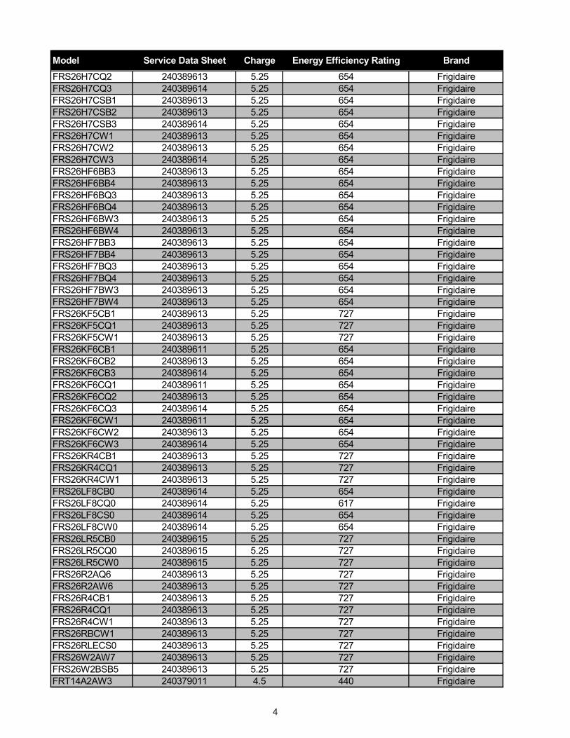
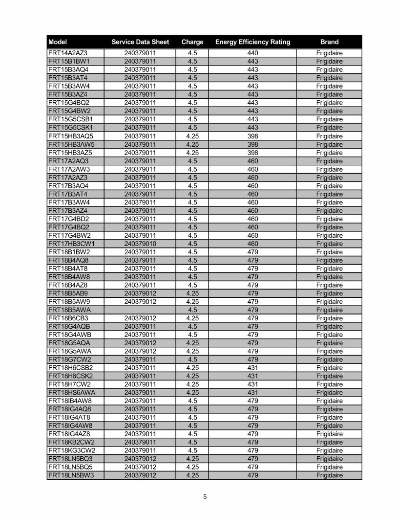
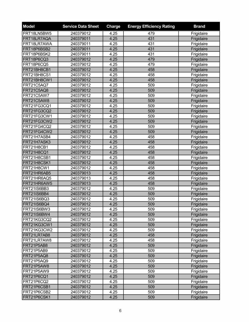
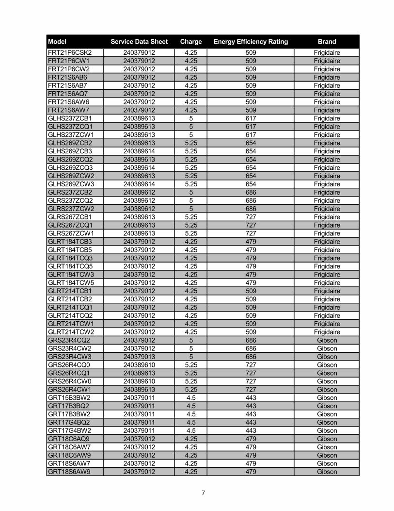
Service Data Sheet, Refrigerant Charge & Energy Efficiency Rating Indexes ------------------- 3 - 9
Troubleshooting Guide --------------------------------------------------------------------------------------------- 10 - 14
Appendix A - Service Data Sheets
240379010 --------------------------------------------------------------------------------------------------------- A1 - A2
240379011 --------------------------------------------------------------------------------------------------------- A3 - A4
240379012 --------------------------------------------------------------------------------------------------------- A5 - A6
240379013 --------------------------------------------------------------------------------------------------------- A7 - A8
240389610 --------------------------------------------------------------------------------------------------------- A9 - A10
240389611 --------------------------------------------------------------------------------------------------------- A11 - A12
240389612 --------------------------------------------------------------------------------------------------------- A13 - A14
240389613 --------------------------------------------------------------------------------------------------------- A15 - A16
240389614 --------------------------------------------------------------------------------------------------------- A17 - A18
240389015 --------------------------------------------------------------------------------------------------------- A19 - A20
241532600 --------------------------------------------------------------------------------------------------------- A21- A22
2
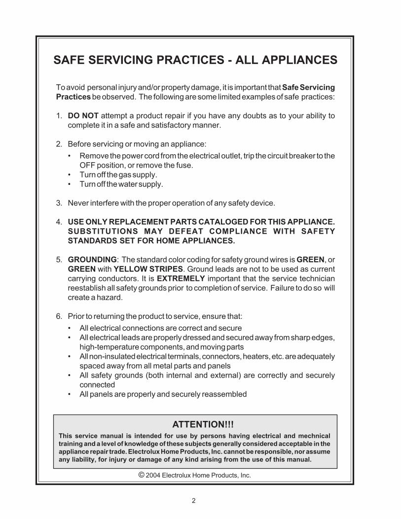
ATTENTION!!!This service manual is intended for use by persons having electrical and mechnicaltraining and a level of knowledge of these subjects generally considered acceptable in theappliance repair trade. Electrolux Home Products, Inc. cannot be responsible, nor assumeany liability, for injury or damage of any kind arising from the use of this manual.
© 2004 Electrolux Home Products, Inc.
SAFE SERVICING PRACTICES - ALL APPLIANCES
To avoid personal injury and/or property damage, it is important that Safe ServicingPractices be observed. The following are some limited examples of safe practices:
1. DO NOT attempt a product repair if you have any doubts as to your ability tocomplete it in a safe and satisfactory manner.
2. Before servicing or moving an appliance:• Remove the power cord from the electrical outlet, trip the circuit breaker to the
OFF position, or remove the fuse.• Turn off the gas supply.• Turn off the water supply.
3. Never interfere with the proper operation of any safety device.
4. USE ONLY REPLACEMENT PARTS CATALOGED FOR THIS APPLIANCE.SUBSTITUTIONS MAY DEFEAT COMPLIANCE WITH SAFETYSTANDARDS SET FOR HOME APPLIANCES.
5. GROUNDING: The standard color coding for safety ground wires is GREEN, orGREEN with YELLOW STRIPES. Ground leads are not to be used as currentcarrying conductors. It is EXTREMELY important that the service technicianreestablish all safety grounds prior to completion of service. Failure to do so willcreate a hazard.
6. Prior to returning the product to service, ensure that:• All electrical connections are correct and secure• All electrical leads are properly dressed and secured away from sharp edges,
high-temperature components, and moving parts• All non-insulated electrical terminals, connectors, heaters, etc. are adequately
spaced away from all metal parts and panels• All safety grounds (both internal and external) are correctly and securely
connected• All panels are properly and securely reassembled
3
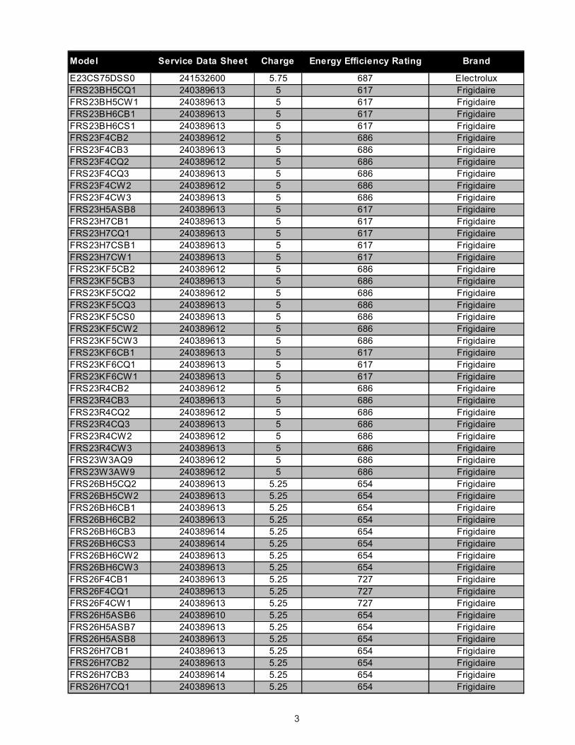
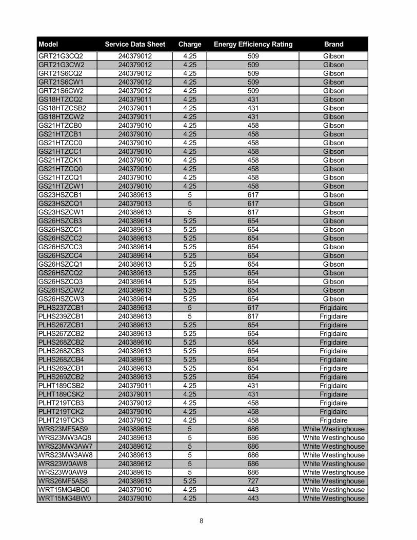
Model Service Data Sheet Charge Energy Efficiency Rating Brand
E23CS75DSS0 241532600 5.75 687 ElectroluxFRS23BH5CQ1 240389613 5 617 FrigidaireFRS23BH5CW1 240389613 5 617 FrigidaireFRS23BH6CB1 240389613 5 617 FrigidaireFRS23BH6CS1 240389613 5 617 FrigidaireFRS23F4CB2 240389612 5 686 FrigidaireFRS23F4CB3 240389613 5 686 FrigidaireFRS23F4CQ2 240389612 5 686 FrigidaireFRS23F4CQ3 240389613 5 686 FrigidaireFRS23F4CW2 240389612 5 686 FrigidaireFRS23F4CW3 240389613 5 686 FrigidaireFRS23H5ASB8 240389613 5 617 FrigidaireFRS23H7CB1 240389613 5 617 FrigidaireFRS23H7CQ1 240389613 5 617 FrigidaireFRS23H7CSB1 240389613 5 617 FrigidaireFRS23H7CW1 240389613 5 617 FrigidaireFRS23KF5CB2 240389612 5 686 FrigidaireFRS23KF5CB3 240389613 5 686 FrigidaireFRS23KF5CQ2 240389612 5 686 FrigidaireFRS23KF5CQ3 240389613 5 686 FrigidaireFRS23KF5CS0 240389613 5 686 FrigidaireFRS23KF5CW2 240389612 5 686 FrigidaireFRS23KF5CW3 240389613 5 686 FrigidaireFRS23KF6CB1 240389613 5 617 FrigidaireFRS23KF6CQ1 240389613 5 617 FrigidaireFRS23KF6CW1 240389613 5 617 FrigidaireFRS23R4CB2 240389612 5 686 FrigidaireFRS23R4CB3 240389613 5 686 FrigidaireFRS23R4CQ2 240389612 5 686 FrigidaireFRS23R4CQ3 240389613 5 686 FrigidaireFRS23R4CW2 240389612 5 686 FrigidaireFRS23R4CW3 240389613 5 686 FrigidaireFRS23W3AQ9 240389612 5 686 FrigidaireFRS23W3AW9 240389612 5 686 FrigidaireFRS26BH5CQ2 240389613 5.25 654 FrigidaireFRS26BH5CW2 240389613 5.25 654 FrigidaireFRS26BH6CB1 240389613 5.25 654 FrigidaireFRS26BH6CB2 240389613 5.25 654 FrigidaireFRS26BH6CB3 240389614 5.25 654 FrigidaireFRS26BH6CS3 240389614 5.25 654 FrigidaireFRS26BH6CW2 240389613 5.25 654 FrigidaireFRS26BH6CW3 240389613 5.25 654 FrigidaireFRS26F4CB1 240389613 5.25 727 FrigidaireFRS26F4CQ1 240389613 5.25 727 FrigidaireFRS26F4CW1 240389613 5.25 727 FrigidaireFRS26H5ASB6 240389610 5.25 654 FrigidaireFRS26H5ASB7 240389613 5.25 654 FrigidaireFRS26H5ASB8 240389613 5.25 654 FrigidaireFRS26H7CB1 240389613 5.25 654 FrigidaireFRS26H7CB2 240389613 5.25 654 FrigidaireFRS26H7CB3 240389614 5.25 654 FrigidaireFRS26H7CQ1 240389613 5.25 654 Frigidaire
4
Model Service Data Sheet Charge Energy Efficiency Rating BrandFRS26H7CQ2 240389613 5.25 654 FrigidaireFRS26H7CQ3 240389614 5.25 654 FrigidaireFRS26H7CSB1 240389613 5.25 654 FrigidaireFRS26H7CSB2 240389613 5.25 654 FrigidaireFRS26H7CSB3 240389614 5.25 654 FrigidaireFRS26H7CW1 240389613 5.25 654 FrigidaireFRS26H7CW2 240389613 5.25 654 FrigidaireFRS26H7CW3 240389614 5.25 654 FrigidaireFRS26HF6BB3 240389613 5.25 654 FrigidaireFRS26HF6BB4 240389613 5.25 654 FrigidaireFRS26HF6BQ3 240389613 5.25 654 FrigidaireFRS26HF6BQ4 240389613 5.25 654 FrigidaireFRS26HF6BW3 240389613 5.25 654 FrigidaireFRS26HF6BW4 240389613 5.25 654 FrigidaireFRS26HF7BB3 240389613 5.25 654 FrigidaireFRS26HF7BB4 240389613 5.25 654 FrigidaireFRS26HF7BQ3 240389613 5.25 654 FrigidaireFRS26HF7BQ4 240389613 5.25 654 FrigidaireFRS26HF7BW3 240389613 5.25 654 FrigidaireFRS26HF7BW4 240389613 5.25 654 FrigidaireFRS26KF5CB1 240389613 5.25 727 FrigidaireFRS26KF5CQ1 240389613 5.25 727 FrigidaireFRS26KF5CW1 240389613 5.25 727 FrigidaireFRS26KF6CB1 240389611 5.25 654 FrigidaireFRS26KF6CB2 240389613 5.25 654 FrigidaireFRS26KF6CB3 240389614 5.25 654 FrigidaireFRS26KF6CQ1 240389611 5.25 654 FrigidaireFRS26KF6CQ2 240389613 5.25 654 FrigidaireFRS26KF6CQ3 240389614 5.25 654 FrigidaireFRS26KF6CW1 240389611 5.25 654 FrigidaireFRS26KF6CW2 240389613 5.25 654 FrigidaireFRS26KF6CW3 240389614 5.25 654 FrigidaireFRS26KR4CB1 240389613 5.25 727 FrigidaireFRS26KR4CQ1 240389613 5.25 727 FrigidaireFRS26KR4CW1 240389613 5.25 727 FrigidaireFRS26LF8CB0 240389614 5.25 654 FrigidaireFRS26LF8CQ0 240389614 5.25 617 FrigidaireFRS26LF8CS0 240389614 5.25 654 FrigidaireFRS26LF8CW0 240389614 5.25 654 FrigidaireFRS26LR5CB0 240389615 5.25 727 FrigidaireFRS26LR5CQ0 240389615 5.25 727 FrigidaireFRS26LR5CW0 240389615 5.25 727 FrigidaireFRS26R2AQ6 240389613 5.25 727 FrigidaireFRS26R2AW6 240389613 5.25 727 FrigidaireFRS26R4CB1 240389613 5.25 727 FrigidaireFRS26R4CQ1 240389613 5.25 727 FrigidaireFRS26R4CW1 240389613 5.25 727 FrigidaireFRS26RBCW1 240389613 5.25 727 FrigidaireFRS26RLECS0 240389613 5.25 727 FrigidaireFRS26W2AW7 240389613 5.25 727 FrigidaireFRS26W2BSB5 240389613 5.25 727 FrigidaireFRT14A2AW3 240379011 4.5 440 Frigidaire
5
Model Service Data Sheet Charge Energy Efficiency Rating BrandFRT14A2AZ3 240379011 4.5 440 FrigidaireFRT15B1BW1 240379011 4.5 443 FrigidaireFRT15B3AQ4 240379011 4.5 443 FrigidaireFRT15B3AT4 240379011 4.5 443 FrigidaireFRT15B3AW4 240379011 4.5 443 FrigidaireFRT15B3AZ4 240379011 4.5 443 FrigidaireFRT15G4BQ2 240379011 4.5 443 FrigidaireFRT15G4BW2 240379011 4.5 443 FrigidaireFRT15G5CSB1 240379011 4.5 443 FrigidaireFRT15G5CSK1 240379011 4.5 443 FrigidaireFRT15HB3AQ5 240379011 4.25 398 FrigidaireFRT15HB3AW5 240379011 4.25 398 FrigidaireFRT15HB3AZ5 240379011 4.25 398 FrigidaireFRT17A2AQ3 240379011 4.5 460 FrigidaireFRT17A2AW3 240379011 4.5 460 FrigidaireFRT17A2AZ3 240379011 4.5 460 FrigidaireFRT17B3AQ4 240379011 4.5 460 FrigidaireFRT17B3AT4 240379011 4.5 460 FrigidaireFRT17B3AW4 240379011 4.5 460 FrigidaireFRT17B3AZ4 240379011 4.5 460 FrigidaireFRT17G4BD2 240379011 4.5 460 FrigidaireFRT17G4BQ2 240379011 4.5 460 FrigidaireFRT17G4BW2 240379011 4.5 460 FrigidaireFRT17HB3CW1 240379010 4.5 460 FrigidaireFRT18B1BW2 240379011 4.5 479 FrigidaireFRT18B4AQ8 240379011 4.5 479 FrigidaireFRT18B4AT8 240379011 4.5 479 FrigidaireFRT18B4AW8 240379011 4.5 479 FrigidaireFRT18B4AZ8 240379011 4.5 479 FrigidaireFRT18B5AB9 240379012 4.25 479 FrigidaireFRT18B5AW9 240379012 4.25 479 FrigidaireFRT18B5AWA 4.5 479 FrigidaireFRT18B6CB3 240379012 4.25 479 FrigidaireFRT18G4AQB 240379011 4.5 479 FrigidaireFRT18G4AWB 240379011 4.5 479 FrigidaireFRT18G5AQA 240379012 4.25 479 FrigidaireFRT18G5AWA 240379012 4.25 479 FrigidaireFRT18G7CW2 240379011 4.5 479 FrigidaireFRT18H6CSB2 240379011 4.25 431 FrigidaireFRT18H6CSK2 240379011 4.25 431 FrigidaireFRT18H7CW2 240379011 4.25 431 FrigidaireFRT18HS6AWA 240379011 4.25 431 FrigidaireFRT18IB4AW8 240379011 4.5 479 FrigidaireFRT18IG4AQ8 240379011 4.5 479 FrigidaireFRT18IG4AT8 240379011 4.5 479 FrigidaireFRT18IG4AW8 240379011 4.5 479 FrigidaireFRT18IG4AZ8 240379011 4.5 479 FrigidaireFRT18KB2CW2 240379011 4.5 479 FrigidaireFRT18KG3CW2 240379011 4.5 479 FrigidaireFRT18LN5BQ3 240379012 4.25 479 FrigidaireFRT18LN5BQ5 240379012 4.25 479 FrigidaireFRT18LN5BW3 240379012 4.25 479 Frigidaire
6
Model Service Data Sheet Charge Energy Efficiency Rating BrandFRT18LN5BW5 240379012 4.25 479 FrigidaireFRT18LR7AQA 240379011 4.25 431 FrigidaireFRT18LR7AWA 240379011 4.25 431 FrigidaireFRT18P6BSB2 240379011 4.25 431 FrigidaireFRT18P6BSK2 240379011 4.25 431 FrigidaireFRT18P6CQ3 240379012 4.25 479 FrigidaireFRT18P6CQ5 240379012 4.25 479 FrigidaireFRT21BH8CB1 240379012 4.25 458 FrigidaireFRT21BH8CS1 240379012 4.25 458 FrigidaireFRT21BH8CW1 240379012 4.25 458 FrigidaireFRT21C5AQ7 240379012 4.25 509 FrigidaireFRT21C5AQ8 240379012 4.25 509 FrigidaireFRT21C5AW7 240379012 4.25 509 FrigidaireFRT21C5AW8 240379012 4.25 509 FrigidaireFRT21FG3CQ1 240379012 4.25 509 FrigidaireFRT21FG3CQ2 240379012 4.25 509 FrigidaireFRT21FG3CW1 240379012 4.25 509 FrigidaireFRT21FG3CW2 240379012 4.25 509 FrigidaireFRT21FG4CQ2 240379012 4.25 509 FrigidaireFRT21FG4CW2 240379012 4.25 509 FrigidaireFRT21H7ASB4 240379012 4.25 458 FrigidaireFRT21H7ASK3 240379012 4.25 458 FrigidaireFRT21H8CB1 240379012 4.25 458 FrigidaireFRT21H8CQ1 240379012 4.25 458 FrigidaireFRT21H8CSB1 240379012 4.25 458 FrigidaireFRT21H8CSK1 240379012 4.25 458 FrigidaireFRT21H8CW1 240379012 4.25 458 FrigidaireFRT21HR6AB5 240379013 4.25 458 FrigidaireFRT21HR6AQ5 240379013 4.25 458 FrigidaireFRT21HR6AW5 240379013 4.25 458 FrigidaireFRT21IS6BB3 240379012 4.25 509 FrigidaireFRT21IS6BB4 240379012 4.25 509 FrigidaireFRT21IS6BQ3 240379012 4.25 509 FrigidaireFRT21IS6BQ4 240379012 4.25 509 FrigidaireFRT21IS6BW3 240379012 4.25 509 FrigidaireFRT21IS6BW4 240379012 4.25 509 FrigidaireFRT21KG3CQ2 240379012 4.25 509 FrigidaireFRT21KG3CW1 240379012 4.25 509 FrigidaireFRT21KG3CW2 240379012 4.25 509 FrigidaireFRT21LR7AB8 240379012 4.25 458 FrigidaireFRT21LR7AW8 240379012 4.25 458 FrigidaireFRT21P5AB8 240379012 4.25 509 FrigidaireFRT21P5AB9 240379012 4.25 509 FrigidaireFRT21P5AQ8 240379012 4.25 509 FrigidaireFRT21P5AQ9 240379012 4.25 509 FrigidaireFRT21P5AW8 240379012 4.25 509 FrigidaireFRT21P5AW9 240379012 4.25 509 FrigidaireFRT21P6CQ1 240379012 4.25 509 FrigidaireFRT21P6CQ2 240379012 4.25 509 FrigidaireFRT21P6CSB1 240379012 4.25 509 FrigidaireFRT21P6CSB2 240379012 4.25 509 FrigidaireFRT21P6CSK1 240379012 4.25 509 Frigidaire
7
Model Service Data Sheet Charge Energy Efficiency Rating BrandFRT21P6CSK2 240379012 4.25 509 FrigidaireFRT21P6CW1 240379012 4.25 509 FrigidaireFRT21P6CW2 240379012 4.25 509 FrigidaireFRT21S6AB6 240379012 4.25 509 FrigidaireFRT21S6AB7 240379012 4.25 509 FrigidaireFRT21S6AQ7 240379012 4.25 509 FrigidaireFRT21S6AW6 240379012 4.25 509 FrigidaireFRT21S6AW7 240379012 4.25 509 FrigidaireGLHS237ZCB1 240389613 5 617 FrigidaireGLHS237ZCQ1 240389613 5 617 FrigidaireGLHS237ZCW1 240389613 5 617 FrigidaireGLHS269ZCB2 240389613 5.25 654 FrigidaireGLHS269ZCB3 240389614 5.25 654 FrigidaireGLHS269ZCQ2 240389613 5.25 654 FrigidaireGLHS269ZCQ3 240389614 5.25 654 FrigidaireGLHS269ZCW2 240389613 5.25 654 FrigidaireGLHS269ZCW3 240389614 5.25 654 FrigidaireGLRS237ZCB2 240389612 5 686 FrigidaireGLRS237ZCQ2 240389612 5 686 FrigidaireGLRS237ZCW2 240389612 5 686 FrigidaireGLRS267ZCB1 240389613 5.25 727 FrigidaireGLRS267ZCQ1 240389613 5.25 727 FrigidaireGLRS267ZCW1 240389613 5.25 727 FrigidaireGLRT184TCB3 240379012 4.25 479 FrigidaireGLRT184TCB5 240379012 4.25 479 FrigidaireGLRT184TCQ3 240379012 4.25 479 FrigidaireGLRT184TCQ5 240379012 4.25 479 FrigidaireGLRT184TCW3 240379012 4.25 479 FrigidaireGLRT184TCW5 240379012 4.25 479 FrigidaireGLRT214TCB1 240379012 4.25 509 FrigidaireGLRT214TCB2 240379012 4.25 509 FrigidaireGLRT214TCQ1 240379012 4.25 509 FrigidaireGLRT214TCQ2 240379012 4.25 509 FrigidaireGLRT214TCW1 240379012 4.25 509 FrigidaireGLRT214TCW2 240379012 4.25 509 FrigidaireGRS23R4CQ2 240379012 5 686 GibsonGRS23R4CW2 240379012 5 686 GibsonGRS23R4CW3 240379013 5 686 GibsonGRS26R4CQ0 240389610 5.25 727 GibsonGRS26R4CQ1 240389613 5.25 727 GibsonGRS26R4CW0 240389610 5.25 727 GibsonGRS26R4CW1 240389613 5.25 727 GibsonGRT15B3BW2 240379011 4.5 443 GibsonGRT17B3BQ2 240379011 4.5 443 GibsonGRT17B3BW2 240379011 4.5 443 GibsonGRT17G4BQ2 240379011 4.5 443 GibsonGRT17G4BW2 240379011 4.5 443 GibsonGRT18C6AQ9 240379012 4.25 479 GibsonGRT18C6AW7 240379012 4.25 479 GibsonGRT18C6AW9 240379012 4.25 479 GibsonGRT18S6AW7 240379012 4.25 479 GibsonGRT18S6AW9 240379012 4.25 479 Gibson
8
Model Service Data Sheet Charge Energy Efficiency Rating BrandGRT21G3CQ2 240379012 4.25 509 GibsonGRT21G3CW2 240379012 4.25 509 GibsonGRT21S6CQ2 240379012 4.25 509 GibsonGRT21S6CW1 240379012 4.25 509 GibsonGRT21S6CW2 240379012 4.25 509 GibsonGS18HTZCQ2 240379011 4.25 431 GibsonGS18HTZCSB2 240379011 4.25 431 GibsonGS18HTZCW2 240379011 4.25 431 GibsonGS21HTZCB0 240379010 4.25 458 GibsonGS21HTZCB1 240379010 4.25 458 GibsonGS21HTZCC0 240379010 4.25 458 GibsonGS21HTZCC1 240379010 4.25 458 GibsonGS21HTZCK1 240379010 4.25 458 GibsonGS21HTZCQ0 240379010 4.25 458 GibsonGS21HTZCQ1 240379010 4.25 458 GibsonGS21HTZCW1 240379010 4.25 458 GibsonGS23HSZCB1 240389613 5 617 GibsonGS23HSZCQ1 240379013 5 617 GibsonGS23HSZCW1 240389613 5 617 GibsonGS26HSZCB3 240389614 5.25 654 GibsonGS26HSZCC1 240389613 5.25 654 GibsonGS26HSZCC2 240389613 5.25 654 GibsonGS26HSZCC3 240389614 5.25 654 GibsonGS26HSZCC4 240389614 5.25 654 GibsonGS26HSZCQ1 240389613 5.25 654 GibsonGS26HSZCQ2 240389613 5.25 654 GibsonGS26HSZCQ3 240389614 5.25 654 GibsonGS26HSZCW2 240389613 5.25 654 GibsonGS26HSZCW3 240389614 5.25 654 GibsonPLHS237ZCB1 240389613 5 617 FrigidairePLHS239ZCB1 240389613 5 617 FrigidairePLHS267ZCB1 240389613 5.25 654 FrigidairePLHS267ZCB2 240389613 5.25 654 FrigidairePLHS268ZCB2 240389610 5.25 654 FrigidairePLHS268ZCB3 240389613 5.25 654 FrigidairePLHS268ZCB4 240389613 5.25 654 FrigidairePLHS269ZCB1 240389613 5.25 654 FrigidairePLHS269ZCB2 240389613 5.25 654 FrigidairePLHT189CSB2 240379011 4.25 431 FrigidairePLHT189CSK2 240379011 4.25 431 FrigidairePLHT219TCB3 240379012 4.25 458 FrigidairePLHT219TCK2 240379010 4.25 458 FrigidairePLHT219TCK3 240379012 4.25 458 FrigidaireWRS23MF5AS9 240389615 5 686 White WestinghouseWRS23MW3AQ8 240389613 5 686 White WestinghouseWRS23MW3AW7 240389612 5 686 White WestinghouseWRS23MW3AW8 240389613 5 686 White WestinghouseWRS23W0AW8 240389612 5 686 White WestinghouseWRS23W0AW9 240389615 5 686 White WestinghouseWRS26MF5AS8 240389613 5.25 727 White WestinghouseWRT15MG4BQ0 240379010 4.25 443 White WestinghouseWRT15MG4BW0 240379010 4.25 443 White Westinghouse
9
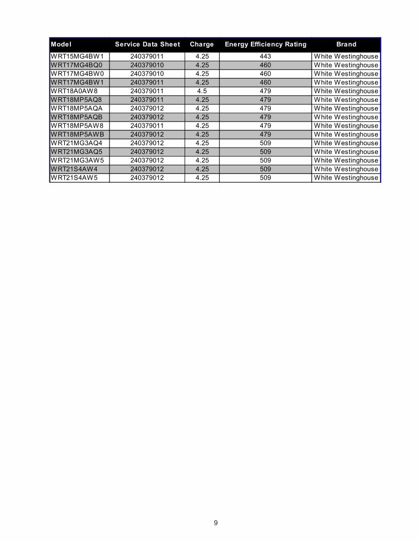
Model Service Data Sheet Charge Energy Efficiency Rating Brand
WRT15MG4BW1 240379011 4.25 443 White WestinghouseWRT17MG4BQ0 240379010 4.25 460 White WestinghouseWRT17MG4BW0 240379010 4.25 460 White WestinghouseWRT17MG4BW1 240379011 4.25 460 White WestinghouseWRT18A0AW8 240379011 4.5 479 White WestinghouseWRT18MP5AQ8 240379011 4.25 479 White WestinghouseWRT18MP5AQA 240379012 4.25 479 White WestinghouseWRT18MP5AQB 240379012 4.25 479 White WestinghouseWRT18MP5AW8 240379011 4.25 479 White WestinghouseWRT18MP5AWB 240379012 4.25 479 White WestinghouseWRT21MG3AQ4 240379012 4.25 509 White WestinghouseWRT21MG3AQ5 240379012 4.25 509 White WestinghouseWRT21MG3AW5 240379012 4.25 509 White WestinghouseWRT21S4AW4 240379012 4.25 509 White WestinghouseWRT21S4AW5 240379012 4.25 509 White Westinghouse
10
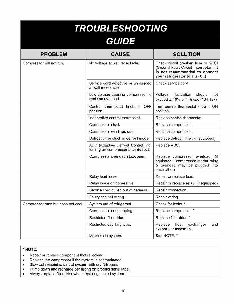
TROUBLESHOOTING GUIDE
PROBLEM CAUSE SOLUTION No voltage at wall receptacle. Check circuit breaker, fuse or GFCI
(Ground Fault Circuit Interruptor - It is not recommended to connect your refrigerator to a GFCI.)
Service cord defective or unplugged at wall receptacle.
Check service cord.
Low voltage causing compressor to cycle on overload.
Voltage fluctuation should not exceed ± 10% of 115 vac (104-127)
Control thermostat knob in OFF position.
Turn control thermostat knob to ON position.
Inoperative control thermostat. Replace control thermostat
Compressor stuck. Replace compressor.
Compressor windings open. Replace compressor.
Defrost timer stuck in defrost mode. Replace defrost timer. (if equipped)
ADC (Adaptive Defrost Control) not turning on compressor after defrost.
Replace ADC.
Compressor overload stuck open. Replace compressor overload. (if equipped – compressor starter relay & overload may be plugged into each other)
Relay lead loose. Repair or replace lead.
Relay loose or inoperative. Repair or replace relay. (if equipped)
Service cord pulled out of harness. Repair connection.
Compressor will not run.
Faulty cabinet wiring. Repair wiring.
System out of refrigerant. Check for leaks. *
Compressor not pumping. Replace compressor. *
Restricted filter drier. Replace filter drier. *
Restricted capillary tube. Replace heat exchanger and evaporator assembly.
Compressor runs but does not cool.
Moisture in system. See NOTE. *
* NOTE: • Repair or replace component that is leaking. • Replace the compressor if the system is contaminated. • Blow out remaining part of system with dry Nitrogen. • Pump down and recharge per listing on product serial label. • Always replace filter drier when repairing sealed system.
11
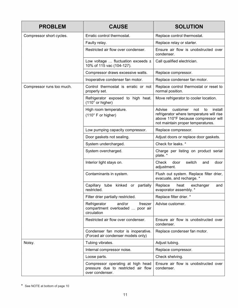
* See NOTE at bottom of page 10
PROBLEM CAUSE SOLUTION Erratic control thermostat. Replace control thermostat.
Faulty relay. Replace relay or starter.
Restricted air flow over condenser. Ensure air flow is unobstructed over condenser.
Low voltage … fluctuation exceeds ± 10% of 115 vac (104-127).
Call qualified electrician.
Compressor draws excessive watts. Replace compressor.
Compressor short cycles.
Inoperative condenser fan motor. Replace condenser fan motor.
Control thermostat is erratic or not properly set.
Replace control thermostat or reset to normal position.
Refrigerator exposed to high heat. (110° or higher)
Move refrigerator to cooler location.
High room temperature. (110° F or higher)
Advise customer not to install refrigerator where temperature will rise above 110°F because compressor will not maintain proper temperatures.
Low pumping capacity compressor. Replace compressor.
Door gaskets not sealing. Adjust doors or replace door gaskets.
System undercharged. Check for leaks. *
System overcharged. Charge per listing on product serial plate. *
Interior light stays on. Check door switch and door adjustment.
Contaminants in system. Flush out system. Replace filter drier, evacuate, and recharge. *
Capillary tube kinked or partially restricted.
Replace heat exchanger and evaporator assembly. *
Filter drier partially restricted. Replace filter drier. *
Refrigerator and/or freezer compartment overloaded … poor air circulation
Advise customer.
Restricted air flow over condenser. Ensure air flow is unobstructed over condenser.
Compressor runs too much.
Condenser fan motor is inoperative. (Forced air condenser models only)
Replace condenser fan motor.
Tubing vibrates. Adjust tubing.
Internal compressor noise. Replace compressor.
Loose parts. Check shelving.
Noisy.
Compressor operating at high head pressure due to restricted air flow over condenser.
Ensure air flow is unobstructed over condenser.
12
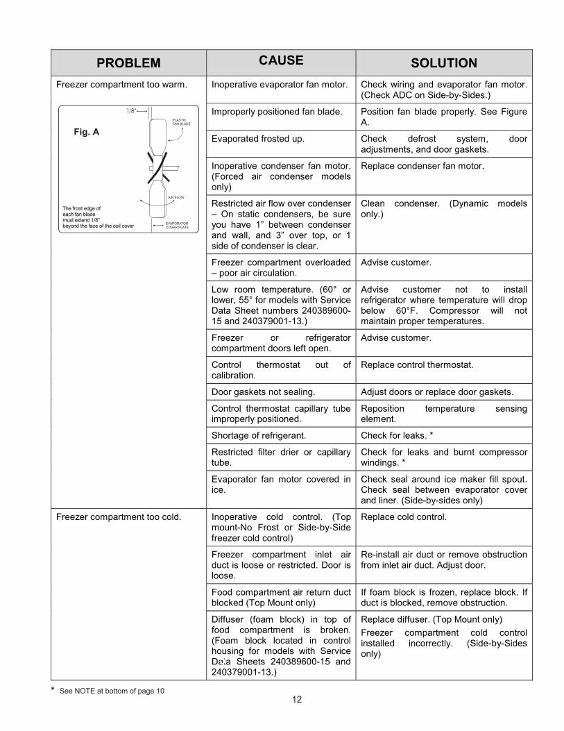
PROBLEM CAUSE SOLUTION Inoperative evaporator fan motor. Check wiring and evaporator fan motor.
(Check ADC on Side-by-Sides.)
Improperly positioned fan blade. Position fan blade properly. See Figure A.
Evaporated frosted up. Check defrost system, door adjustments, and door gaskets.
Inoperative condenser fan motor. (Forced air condenser models only)
Replace condenser fan motor.
Restricted air flow over condenser – On static condensers, be sure you have 1” between condenser and wall, and 3” over top, or 1 side of condenser is clear.
Clean condenser. (Dynamic models only.)
Freezer compartment overloaded – poor air circulation.
Advise customer.
Low room temperature. (60° or lower, 55° for models with Service Data Sheet numbers 240389600-15 and 240379001-13.)
Advise customer not to install refrigerator where temperature will drop below 60°F. Compressor will not maintain proper temperatures.
Freezer or refrigerator compartment doors left open.
Advise customer.
Control thermostat out of calibration.
Replace control thermostat.
Door gaskets not sealing. Adjust doors or replace door gaskets.
Control thermostat capillary tube improperly positioned.
Reposition temperature sensing element.
Shortage of refrigerant. Check for leaks. *
Restricted filter drier or capillary tube.
Check for leaks and burnt compressor windings. *
Freezer compartment too warm.
Evaporator fan motor covered in ice.
Check seal around ice maker fill spout. Check seal between evaporator cover and liner. (Side-by-sides only)
Inoperative cold control. (Top mount-No Frost or Side-by-Side freezer cold control)
Replace cold control.
Freezer compartment inlet air duct is loose or restricted. Door is loose.
Re-install air duct or remove obstruction from inlet air duct. Adjust door.
Food compartment air return duct blocked (Top Mount only)
If foam block is frozen, replace block. If duct is blocked, remove obstruction.
Freezer compartment too cold.
Diffuser (foam block) in top of food compartment is broken. (Foam block located in control housing for models with Service Data Sheets 240389600-15 and 240379001-13.)
Replace diffuser. (Top Mount only) Freezer compartment cold control installed incorrectly. (Side-by-Sides only)
Fig. A
* See NOTE at bottom of page 10
5
13
* See NOTE at bottom of page 10.
PROBLEM CAUSE SOLUTION Inoperative evaporator fan motor. Check wiring and evaporator fan motor.
(Check ADC on Side-by-Sides.)
Improperly positioned fan blade. Position fan blade properly. See page 12, Figure A.
Evaporated frosted up. Check defrost system, door adjustments, and door gaskets.
Refrigerator compartment overloaded – poor air circulation.
Advise customer.
Low room temperature. (60° or lower, 55° for models with Service Data Sheet numbers 240389600-15 and 240379001-13.)
Advise customer not to install refrigerator where temperature will drop below 60°F. Compressor will not maintain proper temperatures.
Freezer or refrigerator compartment doors left open.
Advise customer.
Damper control out of calibration or not opening.
Replace damper control.
Shortage of refrigerant. Check for leaks. *
Restricted filter drier or capillary tube.
Check for leaks and burnt compressor windings. *
Refrigerator compartment inlet air duct loose or restricted. Door is loose.
Re-install air duct or remove obstruction from air duct. Adjust door.
Freezer compartment return air duct restricted.
Remove obstruction from return air duct.
Control thermostat knob set at too warm a position.
Set control knob to a colder position.
Inoperative or erratic refrigerator/freezer compartment door switch.
Replace door switch.
Freezer compartment inlet air duct is loose or restricted. Door is loose.
Re-install air duct or remove obstruction from inlet air duct. Adjust door.
Refrigerator compartment too warm.
Food compartment air return duct blocked (Top Mount only)
If foam block is frozen, replace block. If duct is blocked, remove obstruction.
Inoperative cold control. Replace cold control.
Refrigerator compartment inlet air duct loose or restricted. Door is loose.
Re-install air duct or remove obstruction from air duct. Adjust door.
Refrigerator compartment too cold.
Diffuser (foam block) in top of food compartment is broken. (Foam blocked located in control housing for models with Service Data Sheet numbers 240389600-15 and 240379001-13.)
Replace diffuser. (Top Mounts only)
14
PROBLEM CAUSE SOLUTION Inoperative cold control. Replace cold control.
Refrigerator compartment inlet air duct loose or restricted. Door is loose.
Re-install air duct or remove obstruction from air duct. Adjust door.
Diffuser (foam block) in top of food compartment is broken. (Foam blocked located in control housing for models with Service Data Sheet numbers 240389600-15 and 240379001-13.)
Replace diffuser. (Top Mounts only)
Replace damper control.
Door in damper control not closing or not closing all the way.
Check freezer control bulb for correct positioning to ensure it is installed correctly.
Refrigerator compartment too cold. (Continued)
Cold air blowing into food compartment with damper door closed all the way.
Check foam seal between damper housing and cabinet liner. Check to see that the control box is mounted flush against the cabinet liner.
Inoperative defrost timer. Check wiring. Repair or replace defrost timer.
Defrost thermostat terminates too early. Thermostat is open.
Check for correct positioning of defrost thermostat. Repair or replace.
Refrigerator/Freezer compartment doors left open.
Advise customer.
Open defrost heater. Replace heater.
Evaporator blocked with ice. (See Adaptive defrost Control below for models with Service Data Sheet numbers 240389600-15 and 240379010-13.)
Air leak around ice maker fill tube, or opening.
Seal with permagum.
Ice maker water line and wiring harness openings not sealed.
Seal water line and wiring harness openings.
Drain trough not properly formed. Ensure drain trough is at 90° angle to back of freezer and that lip is up on front and ends.
Frozen drain.
Divider (foam block) frozen. Replace divider. Check drain trough.
Faulty ADC board. Replace ADC board. Adaptive Defrost Control (ADC) not responding correctly. Bad wire between ADC, defrost
heater, and limiter. Check wiring and wiring connectors.

A - 1
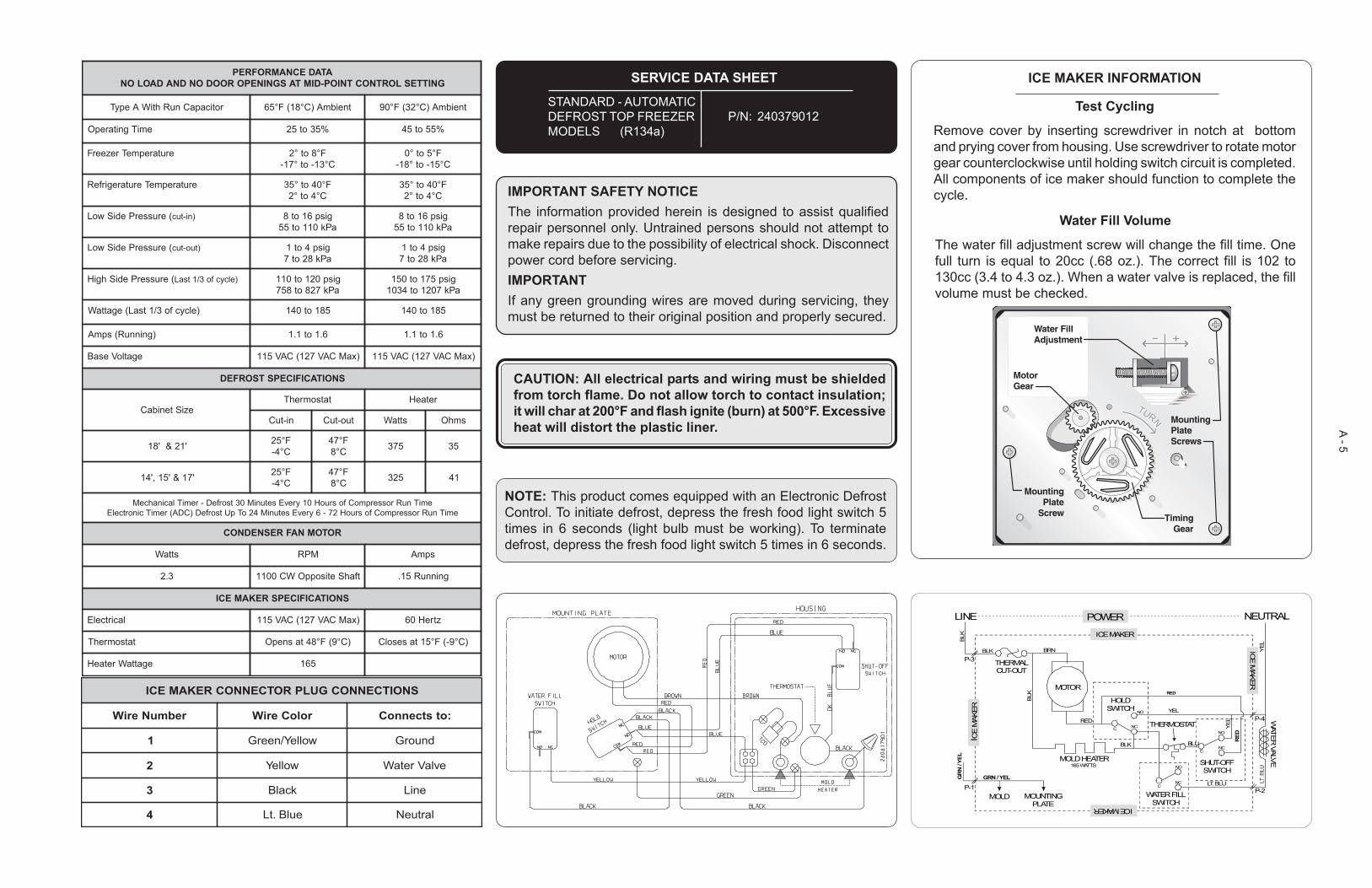
ICE MAKER INFORMATION
Test Cycling
Remove cover by inserting screwdriver in notch at bottomand prying cover from housing. Use screwdriver to rotate motorgear counterclockwise until holding switch circuit is completed.All components of ice maker should function to complete thecycle.
Water Fill Volume
The water fill adjustment screw will change the fill time. Onefull turn is equal to 20cc (.68 oz.). The correct fill is 102 to130cc (3.4 to 4.3 oz.). When a water valve is replaced, the fillvolume must be checked.
IMPORTANT SAFETY NOTICEThe information provided herein is designed to assist qualifiedrepair personnel only. Untrained persons should not attempt tomake repairs due to the possibility of electrical shock. Disconnectpower cord before servicing.IMPORTANTIf any green grounding wires are moved during servicing, theymust be returned to their original position and properly secured.
NOTE: This product comes equipped with an Electronic DefrostControl. To initiate defrost, depress the fresh food light switch 5times in 6 seconds (light bulb must be working). To terminatedefrost, depress the fresh food light switch 5 times in 6 seconds.
CAUTION: All electrical parts and wiring must be shieldedfrom torch flame. Do not allow torch to contact insulation;it will char at 200°F and flash ignite (burn) at 500°F. Excessiveheat will distort the plastic liner.
POWER
ICE MAKER
ICE MAKER
ICE
MAK
ER
ICE M
AKER
WATER
VALVE
LINE
THERMALCUT-OUT
HOLDSWITCH
THERMOSTAT
SHUT-OFFSWITCH
WATER FILLSWITCH
MOLD HEATER
MOLD MOUNTINGPLATE
165 WATTS
MOTOR
NEUTRAL
BLK
BLK
BLK
BLK BLU
C
C
C
NO
NO
NO
NC
NC
NC
LT. BLU
BRN
RED
GRN / YELGR
N /
YEL
RED
RED
YEL
YEL
YEL
P-3
P-1 P-2
P-4
SERVICE DATA SHEET
STANDARD - AUTOMATICDEFROST TOP FREEZERMODELS (R134a)
P/N: 240379010
SNOITCENNOCGULPROTCENNOCREKAMECI
rebmuNeriW roloCeriW :otstcennoC
1 wolleY/neerG dnuorG
2 wolleY evlaVretaW
3 kcalB eniL
4 eulB.tL lartueN
ATADECNAMROFREPGNITTESLORTNOCTNIOP-DIMTASGNINEPOROODONDNADAOLON
roticapaCnuRhtiWAepyT tneibmA)C°81(F°56 tneibmA)C°23(F°09
emiTgnitarepO %53ot52 %55ot54
erutarepmeTrezeerF F°8ot°2C°31-ot°71-
F°5ot°0C°51-ot°81-
erutarepmeTerutaregirfeR F°04ot°53C°4ot°2
F°04ot°53C°4ot°2
(erusserPediSwoL )ni-tuc gisp61ot8aPk011ot55
gisp61ot8aPk011ot55
(erusserPediSwoL )tuo-tuc gisp4ot1aPk82ot7
gisp4ot1aPk82ot7
(erusserPediShgiH )elcycfo3/1tsaL gisp021ot011aPk728ot857
gisp571ot051aPk7021ot4301
)elcycfo3/1tsaL(egattaW 581ot041 581ot041
)gninnuR(spmA 6.1ot1.1 6.1ot1.1
egatloVesaB )xaMCAV721(CAV511 )xaMCAV721(CAV511
SNOITACIFICEPSTSORFED
eziStenibaCtatsomrehT retaeH
ni-tuC tuo-tuC sttaW smhO
'12&'81 F°52C°4-
F°74C°8 573 53
'71&'51,'41 F°52C°4-
F°74C°8 523 14
emiTnuRrosserpmoCfosruoH01yrevEsetuniM03tsorfeD-remiTlacinahceMemiTnuRrosserpmoCfosruoH27-6yrevEsetuniM42oTpUtsorfeD)CDA(remiTcinortcelE
ROTOMNAFRESNEDNOC
sttaW MPR spmA
3.2 tfahSetisoppOWC0011 gninnuR51.
SNOITACIFICEPSREKAMECI
lacirtcelE )xaMCAV721(CAV511 ztreH06
tatsomrehT )C°9(F°84tasnepO )C°9-(F°51tasesolC
egattaWretaeH 561
A - 2
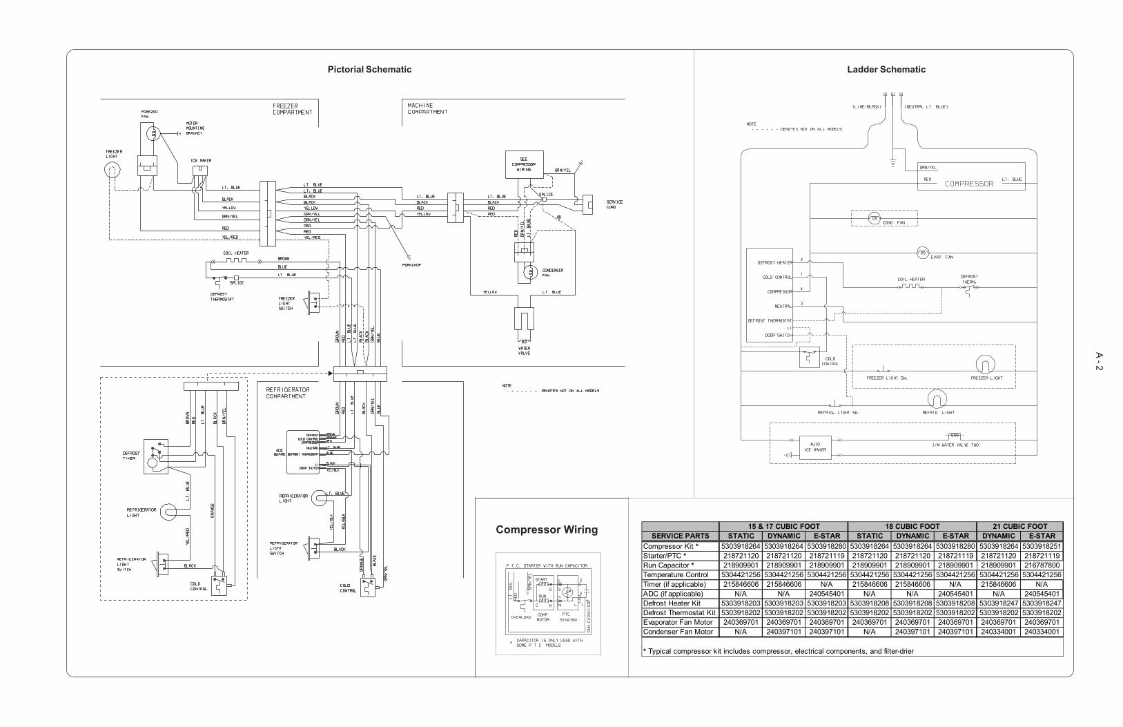
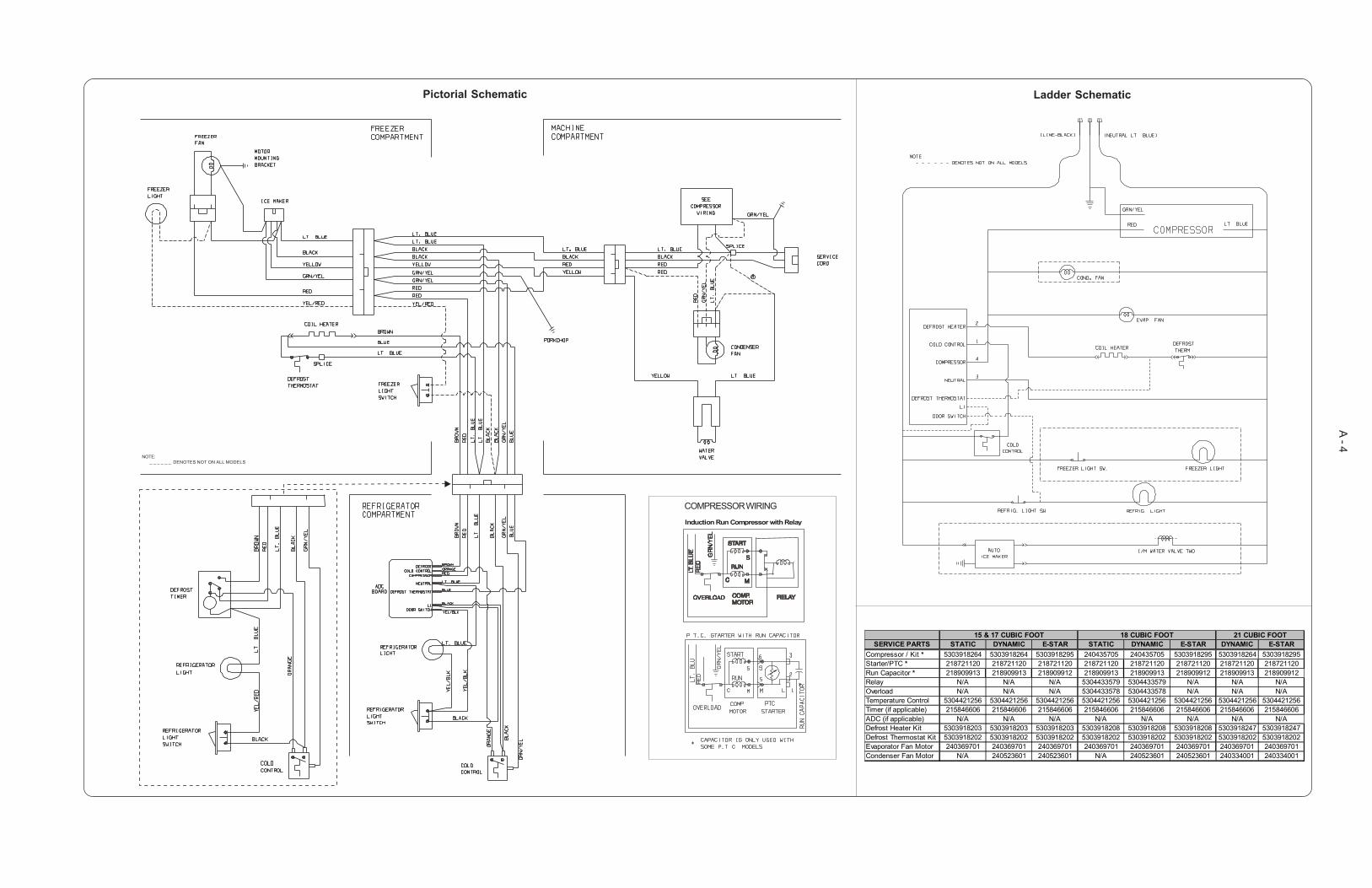
Pictorial Schematic Ladder Schematic
Compressor Wiring 15 & 17 CUBIC FOOT 18 CUBIC FOOTSERVICE PARTS STATIC DYNAMIC E-STAR STATIC DYNAMIC E-STAR DYNAMIC E-STAR
Compressor Kit * 5303918264 5303918264 5303918280 5303918264 5303918264 5303918280 5303918264 5303918251Starter/PTC * 218721120 218721120 218721119 218721120 218721120 218721119 218721120 218721119Run Capacitor * 218909901 218909901 218909901 218909901 218909901 218909901 218909901 216787800Temperature Control 5304421256 5304421256 5304421256 5304421256 5304421256 5304421256 5304421256 5304421256Timer (if applicable) 215846606 215846606 N/A 215846606 215846606 N/A 215846606 N/AADC (if applicable) N/A N/A 240545401 N/A N/A 240545401 N/A 240545401Defrost Heater Kit 5303918203 5303918203 5303918203 5303918208 5303918208 5303918208 5303918247 5303918247Defrost Thermostat Kit 5303918202 5303918202 5303918202 5303918202 5303918202 5303918202 5303918202 5303918202Evaporator Fan Motor 240369701 240369701 240369701 240369701 240369701 240369701 240369701 240369701Condenser Fan Motor N/A 240397101 240397101 N/A 240397101 240397101 240334001 240334001
21 CUBIC FOOT
* Typical compressor kit includes compressor, electrical components, and filter-drier

A - 3
ICE MAKER INFORMATION
Test Cycling
Remove cover by inserting screwdriver in notch at bottomand prying cover from housing. Use screwdriver to rotate motorgear counterclockwise until holding switch circuit is completed.All components of ice maker should function to complete thecycle.
Water Fill Volume
The water fill adjustment screw will change the fill time. Onefull turn is equal to 20cc (.68 oz.). The correct fill is 102 to130cc (3.4 to 4.3 oz.). When a water valve is replaced, the fillvolume must be checked.
IMPORTANT SAFETY NOTICEThe information provided herein is designed to assist qualifiedrepair personnel only. Untrained persons should not attempt tomake repairs due to the possibility of electrical shock. Disconnectpower cord before servicing.IMPORTANTIf any green grounding wires are moved during servicing, theymust be returned to their original position and properly secured.
NOTE: This product comes equipped with an Electronic DefrostControl. To initiate defrost, depress the fresh food light switch 5times in 6 seconds (light bulb must be working). To terminatedefrost, depress the fresh food light switch 5 times in 6 seconds.
CAUTION: All electrical parts and wiring must be shieldedfrom torch flame. Do not allow torch to contact insulation;it will char at 200°F and flash ignite (burn) at 500°F. Excessiveheat will distort the plastic liner.
POWER
ICE MAKER
ICE MAKER
ICE
MAK
ER
ICE M
AKER
WATER
VALVE
LINE
THERMALCUT-OUT
HOLDSWITCH
THERMOSTAT
SHUT-OFFSWITCH
WATER FILLSWITCH
MOLD HEATER
MOLD MOUNTINGPLATE
165 WATTS
MOTOR
NEUTRAL
BLK
BLK
BLK
BLK BLU
C
C
C
NO
NO
NO
NC
NC
NC
LT. BLU
BRN
RED
GRN / YELGR
N /
YEL
RED
RED
YEL
YEL
YEL
P-3
P-1 P-2
P-4
SERVICE DATA SHEET
STANDARD - AUTOMATICDEFROST TOP FREEZERMODELS (R134a)
P/N: 240379011
SNOITCENNOCGULPROTCENNOCREKAMECI
rebmuNeriW roloCeriW :otstcennoC
1 wolleY/neerG dnuorG
2 wolleY evlaVretaW
3 kcalB eniL
4 eulB.tL lartueN
ATADECNAMROFREPGNITTESLORTNOCTNIOP-DIMTASGNINEPOROODONDNADAOLON
roticapaCnuRhtiWAepyT tneibmA)C°81(F°56 tneibmA)C°23(F°09
emiTgnitarepO %53ot52 %55ot54
erutarepmeTrezeerF F°8ot°2C°31-ot°71-
F°5ot°0C°51-ot°81-
erutarepmeTerutaregirfeR F°04ot°53C°4ot°2
F°04ot°53C°4ot°2
(erusserPediSwoL )ni-tuc gisp61ot8aPk011ot55
gisp61ot8aPk011ot55
(erusserPediSwoL )tuo-tuc gisp4ot1aPk82ot7
gisp4ot1aPk82ot7
(erusserPediShgiH )elcycfo3/1tsaL gisp021ot011aPk728ot857
gisp571ot051aPk7021ot4301
)elcycfo3/1tsaL(egattaW 581ot041 581ot041
)gninnuR(spmA 6.1ot1.1 6.1ot1.1
egatloVesaB )xaMCAV721(CAV511 )xaMCAV721(CAV511
SNOITACIFICEPSTSORFED
eziStenibaCtatsomrehT retaeH
ni-tuC tuo-tuC sttaW smhO
'12&'81 F°52C°4-
F°74C°8 573 53
'71&'51,'41 F°52C°4-
F°74C°8 523 14
emiTnuRrosserpmoCfosruoH01yrevEsetuniM03tsorfeD-remiTlacinahceMemiTnuRrosserpmoCfosruoH27-6yrevEsetuniM42oTpUtsorfeD)CDA(remiTcinortcelE
ROTOMNAFRESNEDNOC
sttaW MPR spmA
3.2 tfahSetisoppOWC0011 gninnuR51.
SNOITACIFICEPSREKAMECI
lacirtcelE )xaMCAV721(CAV511 ztreH06
tatsomrehT )C°9(F°84tasnepO )C°9-(F°51tasesolC
egattaWretaeH 561
A - 4
Pictorial Schematic Ladder Schematic
15 & 17 CUBIC FOOT 18 CUBIC FOOTSERVICE PARTS STATIC DYNAMIC E-STAR STATIC DYNAMIC E-STAR DYNAMIC E-STAR
Compressor / Kit * 5303918264 5303918264 5303918295 240435705 240435705 5303918295 5303918264 5303918295Starter/PTC * 218721120 218721120 218721120 218721120 218721120 218721120 218721120 218721120Run Capacitor * 218909913 218909913 218909912 218909913 218909913 218909912 218909913 218909912Relay N/A N/A N/A 5304433579 5304433579 N/A N/A N/AOverload N/A N/A N/A 5304433578 5304433578 N/A N/A N/ATemperature Control 5304421256 5304421256 5304421256 5304421256 5304421256 5304421256 5304421256 5304421256Timer (if applicable) 215846606 215846606 215846606 215846606 215846606 215846606 215846606 215846606ADC (if applicable) N/A N/A N/A N/A N/A N/A N/A N/ADefrost Heater Kit 5303918203 5303918203 5303918203 5303918208 5303918208 5303918208 5303918247 5303918247Defrost Thermostat Kit 5303918202 5303918202 5303918202 5303918202 5303918202 5303918202 5303918202 5303918202Evaporator Fan Motor 240369701 240369701 240369701 240369701 240369701 240369701 240369701 240369701Condenser Fan Motor N/A 240523601 240523601 N/A 240523601 240523601 240334001 240334001
21 CUBIC FOOT
NOTE: _ _ _ _ _ _ DENOTES NOT ON ALL MODELS
COMPRESSOR WIRING
Induction Run Compressor with Relay
A - 5
ICE MAKER INFORMATION
Test Cycling
Remove cover by inserting screwdriver in notch at bottomand prying cover from housing. Use screwdriver to rotate motorgear counterclockwise until holding switch circuit is completed.All components of ice maker should function to complete thecycle.
Water Fill Volume
The water fill adjustment screw will change the fill time. Onefull turn is equal to 20cc (.68 oz.). The correct fill is 102 to130cc (3.4 to 4.3 oz.). When a water valve is replaced, the fillvolume must be checked.
IMPORTANT SAFETY NOTICEThe information provided herein is designed to assist qualifiedrepair personnel only. Untrained persons should not attempt tomake repairs due to the possibility of electrical shock. Disconnectpower cord before servicing.IMPORTANTIf any green grounding wires are moved during servicing, theymust be returned to their original position and properly secured.
NOTE: This product comes equipped with an Electronic DefrostControl. To initiate defrost, depress the fresh food light switch 5times in 6 seconds (light bulb must be working). To terminatedefrost, depress the fresh food light switch 5 times in 6 seconds.
CAUTION: All electrical parts and wiring must be shieldedfrom torch flame. Do not allow torch to contact insulation;it will char at 200°F and flash ignite (burn) at 500°F. Excessiveheat will distort the plastic liner.
POWER
ICE MAKER
ICE MAKER
ICE
MAK
ER
ICE M
AKER
WATER
VALVE
LINE
THERMALCUT-OUT
HOLDSWITCH
THERMOSTAT
SHUT-OFFSWITCH
WATER FILLSWITCH
MOLD HEATER
MOLD MOUNTINGPLATE
165 WATTS
MOTOR
NEUTRAL
BLK
BLK
BLK
BLK BLU
C
C
C
NO
NO
NO
NC
NC
NC
LT. BLU
BRN
RED
GRN / YELGR
N /
YEL
RED
RED
YEL
YEL
YEL
P-3
P-1 P-2
P-4
SERVICE DATA SHEET
STANDARD - AUTOMATICDEFROST TOP FREEZERMODELS (R134a)
P/N: 240379012
SNOITCENNOCGULPROTCENNOCREKAMECI
rebmuNeriW roloCeriW :otstcennoC
1 wolleY/neerG dnuorG
2 wolleY evlaVretaW
3 kcalB eniL
4 eulB.tL lartueN
ATADECNAMROFREPGNITTESLORTNOCTNIOP-DIMTASGNINEPOROODONDNADAOLON
roticapaCnuRhtiWAepyT tneibmA)C°81(F°56 tneibmA)C°23(F°09
emiTgnitarepO %53ot52 %55ot54
erutarepmeTrezeerF F°8ot°2C°31-ot°71-
F°5ot°0C°51-ot°81-
erutarepmeTerutaregirfeR F°04ot°53C°4ot°2
F°04ot°53C°4ot°2
(erusserPediSwoL )ni-tuc gisp61ot8aPk011ot55
gisp61ot8aPk011ot55
(erusserPediSwoL )tuo-tuc gisp4ot1aPk82ot7
gisp4ot1aPk82ot7
(erusserPediShgiH )elcycfo3/1tsaL gisp021ot011aPk728ot857
gisp571ot051aPk7021ot4301
)elcycfo3/1tsaL(egattaW 581ot041 581ot041
)gninnuR(spmA 6.1ot1.1 6.1ot1.1
egatloVesaB )xaMCAV721(CAV511 )xaMCAV721(CAV511
SNOITACIFICEPSTSORFED
eziStenibaCtatsomrehT retaeH
ni-tuC tuo-tuC sttaW smhO
'12&'81 F°52C°4-
F°74C°8 573 53
'71&'51,'41 F°52C°4-
F°74C°8 523 14
emiTnuRrosserpmoCfosruoH01yrevEsetuniM03tsorfeD-remiTlacinahceMemiTnuRrosserpmoCfosruoH27-6yrevEsetuniM42oTpUtsorfeD)CDA(remiTcinortcelE
ROTOMNAFRESNEDNOC
sttaW MPR spmA
3.2 tfahSetisoppOWC0011 gninnuR51.
SNOITACIFICEPSREKAMECI
lacirtcelE )xaMCAV721(CAV511 ztreH06
tatsomrehT )C°9(F°84tasnepO )C°9-(F°51tasesolC
egattaWretaeH 561
A - 6
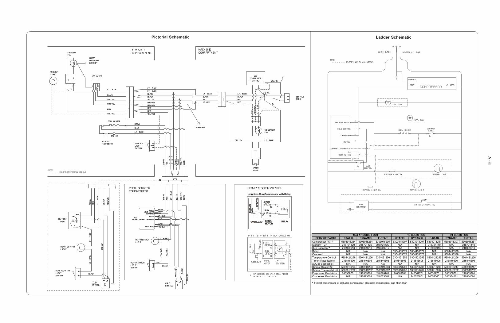
Pictorial Schematic Ladder Schematic
NOTE: _ _ _ _ _ _ DENOTES NOT ON ALL MODELS
COMPRESSOR WIRING
Induction Run Compressor with Relay
15 & 17 CUBIC FOOT 18 CUBIC FOOTSERVICE PARTS STATIC DYNAMIC E-STAR STATIC DYNAMIC E-STAR DYNAMIC E-STAR
Compressor / Kit * 5303918264 5303918264 5303918295 5303918297 5303918297 5303918251 5303918297 5303918251Starter/PTC * 218721120 218721120 218721120 N/A N/A 218721119 N/A 218721119Run Capacitor * 218909913 218909913 218909912 N/A N/A 218909913 N/A 218909913Relay N/A N/A N/A 5304433579 5304433579 N/A 5304433579 N/AOverload N/A N/A N/A 5304433578 5304433578 N/A 5304433578 N/ATemperature Control 5304421256 5304421256 5304421256 5304421256 5304421256 5304421256 5304421256 5304421256Timer (if applicable) 215846606 215846606 215846606 215846606 215846606 215846606 215846606 215846606ADC (if applicable) N/A N/A N/A N/A N/A N/A N/A N/ADefrost Heater Kit 5303918203 5303918203 5303918203 5303918208 5303918208 5303918208 5303918247 5303918247Defrost Thermostat Kit 5303918202 5303918202 5303918202 5303918202 5303918202 5303918202 5303918202 5303918202Evaporator Fan Motor 240369701 240369701 240369701 240369701 240369701 240369701 240369701 240369701Condenser Fan Motor N/A 240523601 240523601 N/A 240523601 240523601 240334001 240334001
21 CUBIC FOOT
* Typical compressor kit includes compressor, electrical components, and filter-drier
A - 7
ICE MAKER INFORMATION
Test Cycling
Remove cover by inserting screwdriver in notch at bottomand prying cover from housing. Use screwdriver to rotate motorgear counterclockwise until holding switch circuit is completed.All components of ice maker should function to complete thecycle.
Water Fill Volume
The water fill adjustment screw will change the fill time. Onefull turn is equal to 20cc (.68 oz.). The correct fill is 102 to130cc (3.4 to 4.3 oz.). When a water valve is replaced, the fillvolume must be checked.
IMPORTANT SAFETY NOTICEThe information provided herein is designed to assist qualifiedrepair personnel only. Untrained persons should not attempt tomake repairs due to the possibility of electrical shock. Disconnectpower cord before servicing.IMPORTANTIf any green grounding wires are moved during servicing, theymust be returned to their original position and properly secured.
NOTE: This product comes equipped with an Electronic DefrostControl. To initiate defrost, depress the fresh food light switch 5times in 6 seconds (light bulb must be working). To terminatedefrost, depress the fresh food light switch 5 times in 6 seconds.
CAUTION: All electrical parts and wiring must be shieldedfrom torch flame. Do not allow torch to contact insulation;it will char at 200°F and flash ignite (burn) at 500°F. Excessiveheat will distort the plastic liner.
POWER
ICE MAKER
ICE MAKER
ICE
MAK
ER
ICE M
AKER
WATER
VALVE
LINE
THERMALCUT-OUT
HOLDSWITCH
THERMOSTAT
SHUT-OFFSWITCH
WATER FILLSWITCH
MOLD HEATER
MOLD MOUNTINGPLATE
165 WATTS
MOTOR
NEUTRAL
BLK
BLK
BLK
BLK BLU
C
C
C
NO
NO
NO
NC
NC
NC
LT. BLU
BRN
RED
GRN / YELGR
N /
YEL
RED
RED
YEL
YEL
YEL
P-3
P-1 P-2
P-4
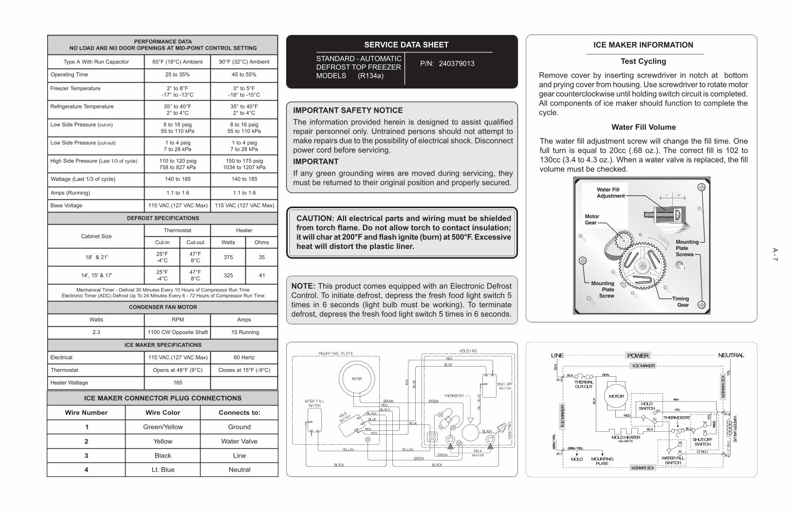
SERVICE DATA SHEET
STANDARD - AUTOMATICDEFROST TOP FREEZERMODELS (R134a)
P/N: 240379013
SNOITCENNOCGULPROTCENNOCREKAMECI
rebmuNeriW roloCeriW :otstcennoC
1 wolleY/neerG dnuorG
2 wolleY evlaVretaW
3 kcalB eniL
4 eulB.tL lartueN
ATADECNAMROFREPGNITTESLORTNOCTNIOP-DIMTASGNINEPOROODONDNADAOLON
roticapaCnuRhtiWAepyT tneibmA)C°81(F°56 tneibmA)C°23(F°09
emiTgnitarepO %53ot52 %55ot54
erutarepmeTrezeerF F°8ot°2C°31-ot°71-
F°5ot°0C°51-ot°81-
erutarepmeTerutaregirfeR F°04ot°53C°4ot°2
F°04ot°53C°4ot°2
(erusserPediSwoL )ni-tuc gisp61ot8aPk011ot55
gisp61ot8aPk011ot55
(erusserPediSwoL )tuo-tuc gisp4ot1aPk82ot7
gisp4ot1aPk82ot7
(erusserPediShgiH )elcycfo3/1tsaL gisp021ot011aPk728ot857
gisp571ot051aPk7021ot4301
)elcycfo3/1tsaL(egattaW 581ot041 581ot041
)gninnuR(spmA 6.1ot1.1 6.1ot1.1
egatloVesaB )xaMCAV721(CAV511 )xaMCAV721(CAV511
SNOITACIFICEPSTSORFED
eziStenibaCtatsomrehT retaeH
ni-tuC tuo-tuC sttaW smhO
'12&'81 F°52C°4-
F°74C°8 573 53
'71&'51,'41 F°52C°4-
F°74C°8 523 14
emiTnuRrosserpmoCfosruoH01yrevEsetuniM03tsorfeD-remiTlacinahceMemiTnuRrosserpmoCfosruoH27-6yrevEsetuniM42oTpUtsorfeD)CDA(remiTcinortcelE
ROTOMNAFRESNEDNOC
sttaW MPR spmA
3.2 tfahSetisoppOWC0011 gninnuR51.
SNOITACIFICEPSREKAMECI
lacirtcelE )xaMCAV721(CAV511 ztreH06
tatsomrehT )C°9(F°84tasnepO )C°9-(F°51tasesolC
egattaWretaeH 561
A - 8
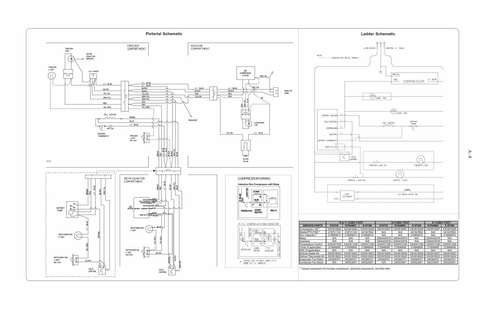
Pictorial Schematic Ladder Schematic
NOTE:
COMPRESSOR WIRING
Induction Run Compressor with Relay
15 & 17 CUBIC FOOT 18 CUBIC FOOTSERVICE PARTS STATIC DYNAMIC E-STAR STATIC DYNAMIC E-STAR DYNAMIC E-STAR
Compressor / Kit * 5303918264 5303918264 5303918299 5303918297 5303918297 5303918299 5303918297 5303918299Starter/PTC/TSD * 218721120 218721120 241527802 N/A N/A 241527802 N/A 241527802Run Capacitor * 218909913 218909913 218909915 N/A N/A 218909915 N/A 218909915Relay N/A N/A N/A 5304433579 5304433579 N/A 5304433579 N/AOverload N/A N/A N/A 5304433578 5304433578 N/A 5304433578 N/ATemperature Control 5304421256 5304421256 5304421256 5304421256 5304421256 5304421256 5304421256 5304421256Timer (if applicable) 215846606 215846606 215846606 215846606 215846606 215846606 215846606 215846606ADC (if applicable) N/A N/A N/A N/A N/A N/A N/A N/ADefrost Heater Kit 5303918203 5303918203 5303918203 5303918208 5303918208 5303918208 5303918247 5303918247Defrost Thermostat Kit 5303918202 5303918202 5303918202 5303918202 5303918202 5303918202 5303918202 5303918202Evaporator Fan Motor 240369701 240369701 240369701 240369701 240369701 240369701 240369701 240369701Condenser Fan Motor N/A 240523601 240523601 N/A 240523601 240523601 240334001 240334001
21 CUBIC FOOT
* Typical compressor kit includes compressor, electrical components, and filter-drier

A - 9
ICE MAKER INFORMATION
Test Cycling
Remove cover by inserting screwdriver in notch at bottomand prying cover from housing. Use screwdriver to rotate motorgear counterclockwise until holding switch circuit is completed.All components of ice maker should function to complete thecycle.
Water Fill Volume
The water fill adjustment screw will change the fill time. Onefull turn is equal to 20cc (.68 oz.). The correct fill is 102 to130cc (3.4 to 4.3 oz.). When a water valve is replaced, the fillvolume must be checked.
POWER
ICE MAKER
ICE MAKER
ICE
MAK
ER
ICE M
AKER
WATER
VALVE
LINE
THERMALCUT-OUT
HOLDSWITCH
THERMOSTAT
SHUT-OFFSWITCH
WATER FILLSWITCH
MOLD HEATER
MOLD MOUNTINGPLATE
165 WATTS
MOTOR
NEUTRAL
BLK
BLK
BLK
BLK BLU
C
C
C
NO
NO
NO
NC
NC
NC
LT. BLU
BRN
RED
GRN / YELGR
N /
YEL
RED
RED
YEL
YEL
YEL
P-3
P-1 P-2
P-4
ATADECNAMROFREPGNITTESLORTNOCTNIOP-DIMTASGNINEPOROODONDNADAOLON
roticapaCtratS/nuRhtiWAepyT tneibmA)C°81(F°56 tneibmA)C°23(F°09
emiTgnitarepO %04ot23 %56ot55
erutarepmeTrezeerF F°4ot°0C°61-ot°81-
F°3ot°1-C°61-ot°81-
erutarepmeTrotaregirfeR F°93ot°43C°4ot°1
F°93ot°43C°4ot°1
(erusserPediSwoL )ni-tuc gisp21ot5aPk38ot43
gisp21ot5aPk38ot43
(erusserPediSwoL )tuo-tuc gisp2ot2-aPk41ot41-
gisp2ot2-aPk41ot41-
(erusserPediShgiH )elcycfo3/1tsaL gisp511ot09aPk397ot126
gisp551ot031aPk9601ot698
)elcycfo3/1tsaL(egattaW 051ot021 061ot031
)gninnuR(spmA 5.1ot2.1 5.1ot2.1
egatloVesaB )xamcav721(cav511 )xamcav721(cav511
SNOITACIFICEPSTSORFED
eziStenibaCtatsomrehT retaeH
ni-tuC tuo-tuC sttaW smhO
'62&'32 F°52C°4-
F°74C°8
054 03
.emitnurrosserpmocfosruoh27ot6yrevesetunim42tsorfeD)CDA(-remiTcinortcelE
ROTOMNAFRESNEDNOC
sttaW MPR spmA
7 tfahSetisoppOWC0011 gninnuR1.
SNOITACIFICEPSREKAMECI
lacirtcelE )xamcav721(cav511 ztreH06
tatsomrehT )C°9(F°84tasnepO )C°9-(F°51tasesolC
egattaWretaeH 561
SNOITCENNOCGULPROTCENNOCREKAMECI
rebmuNeriW roloCeriW :otstcennoC
1 wolleY/neerG dnuorG
2 wolleY evlaVretaW
3 kcalB eniL
4 eulB.tL lartueN
SERVICE DATA SHEET - 240389610R134a
ICE & WATER - AUTOMATIC DEFROSTSIDE BY SIDE MODELS
IMPORTANT SAFETY NOTICEThe information provided herein is designed to assist qualifiedrepair personnel only. Untrained persons should not attempt tomake repairs due to the possibility of electrical shock. Disconnectpower cord before servicing.IMPORTANTIf any green grounding wires are moved during servicing, theymust be returned to their original position and properly secured.
NOTE: This product comes equipped with an Electronic DefrostControl. To initiate defrost, depress the fresh food light switch 5times in 6 seconds (light bulb must be working). To terminatedefrost, depress the fresh food light switch 5 times in 6 seconds.
CAUTION: All electrical parts and wiring must be shieldedfrom torch flame. Do not allow torch to contact insulation;it will char at 200°F and flash ignite (burn) at 500°F. Excessiveheat will distort the plastic liner.
A - 10
STANDARD E-STAR STANDARD E-STARCompressor Kit * 5303918251 5303918251 5303918254 5303918254Starter/PTC * 218721119 218721119 218721119 218721119Run Capacitor * 218787800 218787800 218909901 218909901Temp. Control-Refr 240448303 240448303 240448303 240448303Temp. Control-Frzr 5304429602 5304429602 450226-14 450226-14Timer (if applicable) N/A N/A N/A N/AADC (if applicable) 240554502 240554502 240554502 240554502Defrost Heater Kit 5303918253 5303918253 5303918253 5303918253Defrost Thermostat Kit 5303918214 5303918214 5303918214 5303918214Evaporator Fan Motor 240315803 240315802 240315803 240315802Condenser Fan Motor 240397101 240334001 240397101 240334002
23 CUBIC FOOT 26 CUBIC FOOT
* Typical compressor kit includes compressor, electrical components, and f ilter-drier
SERVICE PARTS
2405
9380
1
A - 11
P-3
P-4
P-2P-1GREEN/YELLOW
GREEN/YELLOW
ATADECNAMROFREPGNITTESLORTNOCTNIOP-DIMTASGNINEPOROODONDNADAOLON
roticapaCtratS/nuRhtiWAepyT tneibmA)C°81(F°56 tneibmA)C°23(F°09
emiTgnitarepO %04ot23 %56ot55
erutarepmeTrezeerF F°4ot°0C°61-ot°81-
F°3ot°1-C°61-ot°81-
erutarepmeTrotaregirfeR F°93ot°43C°4ot°1
F°93ot°43C°4ot°1
(erusserPediSwoL )ni-tuc gisp21ot5aPk38ot43
gisp21ot5aPk38ot43
(erusserPediSwoL )tuo-tuc gisp2ot2-aPk41ot41-
gisp2ot2-aPk41ot41-
(erusserPediShgiH )elcycfo3/1tsaL gisp511ot09aPk397ot126
gisp551ot031aPk9601ot698
)elcycfo3/1tsaL(egattaW 051ot021 061ot031
)gninnuR(spmA 5.1ot2.1 5.1ot2.1
egatloVesaB )xamcav721(cav511 )xamcav721(cav511
SNOITACIFICEPSTSORFED
eziStenibaCtatsomrehT retaeH
ni-tuC tuo-tuC sttaW smhO
'62&'32 F°52C°4-
F°74C°8
054 03
.emitnurrosserpmocfosruoh27ot6yrevesetunim42tsorfeD)CDA(-remiTcinortcelE
ROTOMNAFRESNEDNOC
sttaW MPR spmA
7 tfahSetisoppOWC0011 gninnuR1.
SNOITACIFICEPSREKAMECI
lacirtcelE )xamcav721(cav511 ztreH06
tatsomrehT )C°9(F°84tasnepO )C°9-(F°51tasesolC
egattaWretaeH 561
SNOITCENNOCGULPROTCENNOCREKAMECI
rebmuNeriW roloCeriW :otstcennoC
1 wolleY/neerG dnuorG
2 wolleY evlaVretaW
3 kcalB eniL
4 eulB.tL lartueN
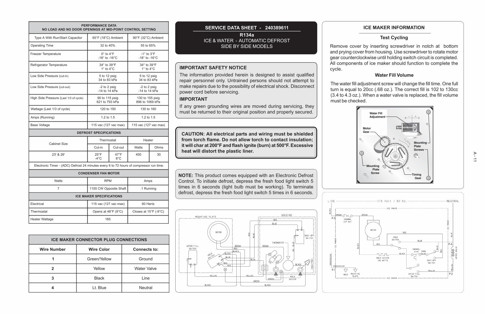
SERVICE DATA SHEET - 240389611R134a
ICE & WATER - AUTOMATIC DEFROSTSIDE BY SIDE MODELS
IMPORTANT SAFETY NOTICEThe information provided herein is designed to assist qualifiedrepair personnel only. Untrained persons should not attempt tomake repairs due to the possibility of electrical shock. Disconnectpower cord before servicing.IMPORTANTIf any green grounding wires are moved during servicing, theymust be returned to their original position and properly secured.
NOTE: This product comes equipped with an Electronic DefrostControl. To initiate defrost, depress the fresh food light switch 5times in 6 seconds (light bulb must be working). To terminatedefrost, depress the fresh food light switch 5 times in 6 seconds.
CAUTION: All electrical parts and wiring must be shieldedfrom torch flame. Do not allow torch to contact insulation;it will char at 200°F and flash ignite (burn) at 500°F. Excessiveheat will distort the plastic liner.
ICE MAKER INFORMATION
Test Cycling
Remove cover by inserting screwdriver in notch at bottomand prying cover from housing. Use screwdriver to rotate motorgear counterclockwise until holding switch circuit is completed.All components of ice maker should function to complete thecycle.
Water Fill Volume
The water fill adjustment screw will change the fill time. One fullturn is equal to 20cc (.68 oz.). The correct fill is 102 to 130cc(3.4 to 4.3 oz.). When a water valve is replaced, the fill volumemust be checked.
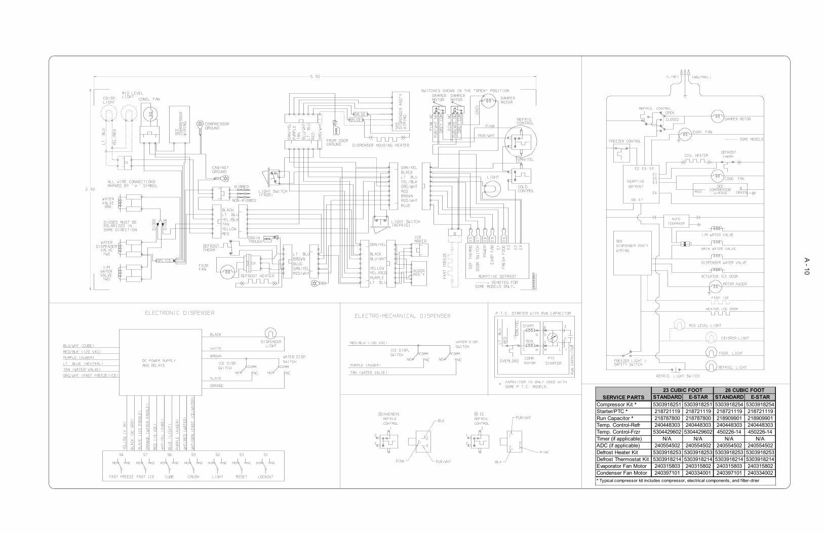
A - 12
STANDARD E-STAR STANDARD E-STARCompressor Kit * 5303918296 5303918251 5303918254 5303918254Starter/PTC * 218721124 218721119 218721119 218721119Run Capacitor * 216787800 216787800 218909901 218909901Temp. Control-Refr 240448303 240448303 240448303 240448303Temp. Control-Frzr 5304429602 5304429602 450226-14 450226-14Timer (if applicable) N/A N/A N/A N/AADC (if applicable) 240554502 240554502 240554502 240554502Defrost Heater Kit 5303918253 5303918253 5303918253 5303918253Defrost Thermostat Kit 5303918214 5303918214 5303918214 5303918214Evaporator Fan Motor 240315803 240315802 240315803 240315802Condenser Fan Motor 240397101 240334001 240397101 240334002
23 CUBIC FOOT 26 CUBIC FOOT
* Typical compressor kit includes compressor, electrical components, and f ilter-drier
SERVICE PARTS
2405
9380
1

A - 13
P-3
P-4
P-2P-1GREEN/YELLOW
GREEN/YELLOW
ATADECNAMROFREPGNITTESLORTNOCTNIOP-DIMTASGNINEPOROODONDNADAOLON
roticapaCtratS/nuRhtiWAepyT tneibmA)C°81(F°56 tneibmA)C°23(F°09
emiTgnitarepO %04ot23 %56ot55
erutarepmeTrezeerF F°4ot°0C°61-ot°81-
F°3ot°1-C°61-ot°81-
erutarepmeTrotaregirfeR F°93ot°43C°4ot°1
F°93ot°43C°4ot°1
(erusserPediSwoL )ni-tuc gisp21ot5aPk38ot43
gisp21ot5aPk38ot43
(erusserPediSwoL )tuo-tuc gisp2ot2-aPk41ot41-
gisp2ot2-aPk41ot41-
(erusserPediShgiH )elcycfo3/1tsaL gisp511ot09aPk397ot126
gisp551ot031aPk9601ot698
)elcycfo3/1tsaL(egattaW 051ot021 061ot031
)gninnuR(spmA 5.1ot2.1 5.1ot2.1
egatloVesaB )xamcav721(cav511 )xamcav721(cav511
SNOITACIFICEPSTSORFED
eziStenibaCtatsomrehT retaeH
ni-tuC tuo-tuC sttaW smhO
'62&'32 F°52C°4-
F°74C°8
054 03
.emitnurrosserpmocfosruoh27ot6yrevesetunim42tsorfeD)CDA(-remiTcinortcelE
ROTOMNAFRESNEDNOC
sttaW MPR spmA
7 tfahSetisoppOWC0011 gninnuR1.
SNOITACIFICEPSREKAMECI
lacirtcelE )xamcav721(cav511 ztreH06
tatsomrehT )C°9(F°84tasnepO )C°9-(F°51tasesolC
egattaWretaeH 561
SNOITCENNOCGULPROTCENNOCREKAMECI
rebmuNeriW roloCeriW :otstcennoC
1 wolleY/neerG dnuorG
2 wolleY evlaVretaW
3 kcalB eniL
4 eulB.tL lartueN
SERVICE DATA SHEET - 240389612R134a
ICE & WATER - AUTOMATIC DEFROSTSIDE BY SIDE MODELS
IMPORTANT SAFETY NOTICEThe information provided herein is designed to assist qualifiedrepair personnel only. Untrained persons should not attempt tomake repairs due to the possibility of electrical shock. Disconnectpower cord before servicing.IMPORTANTIf any green grounding wires are moved during servicing, theymust be returned to their original position and properly secured.
NOTE: This product comes equipped with an Electronic DefrostControl. To initiate defrost, depress the fresh food light switch 5times in 6 seconds (light bulb must be working). To terminatedefrost, depress the fresh food light switch 5 times in 6 seconds.
CAUTION: All electrical parts and wiring must be shieldedfrom torch flame. Do not allow torch to contact insulation;it will char at 200°F and flash ignite (burn) at 500°F. Excessiveheat will distort the plastic liner.
ICE MAKER INFORMATION
Test Cycling
Remove cover by inserting screwdriver in notch at bottomand prying cover from housing. Use screwdriver to rotate motorgear counterclockwise until holding switch circuit is completed.All components of ice maker should function to complete thecycle.
Water Fill Volume
The water fill adjustment screw will change the fill time. One fullturn is equal to 20cc (.68 oz.). The correct fill is 102 to 130cc(3.4 to 4.3 oz.). When a water valve is replaced, the fill volumemust be checked.
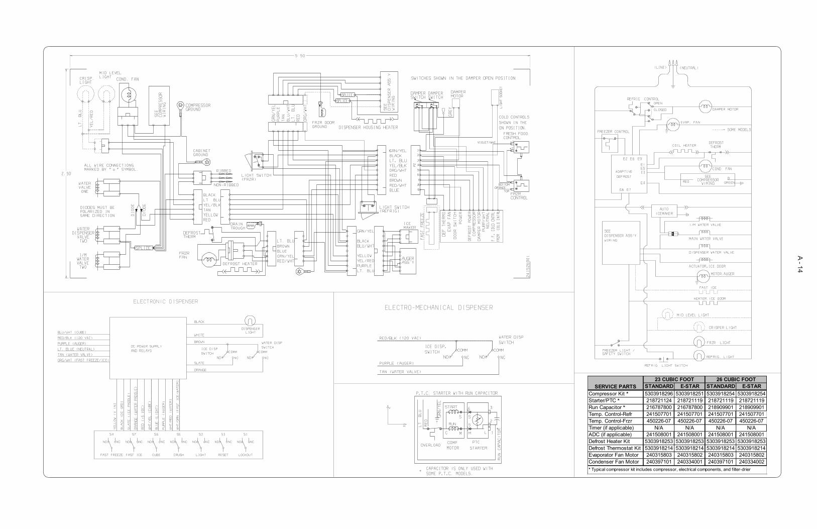
A - 14
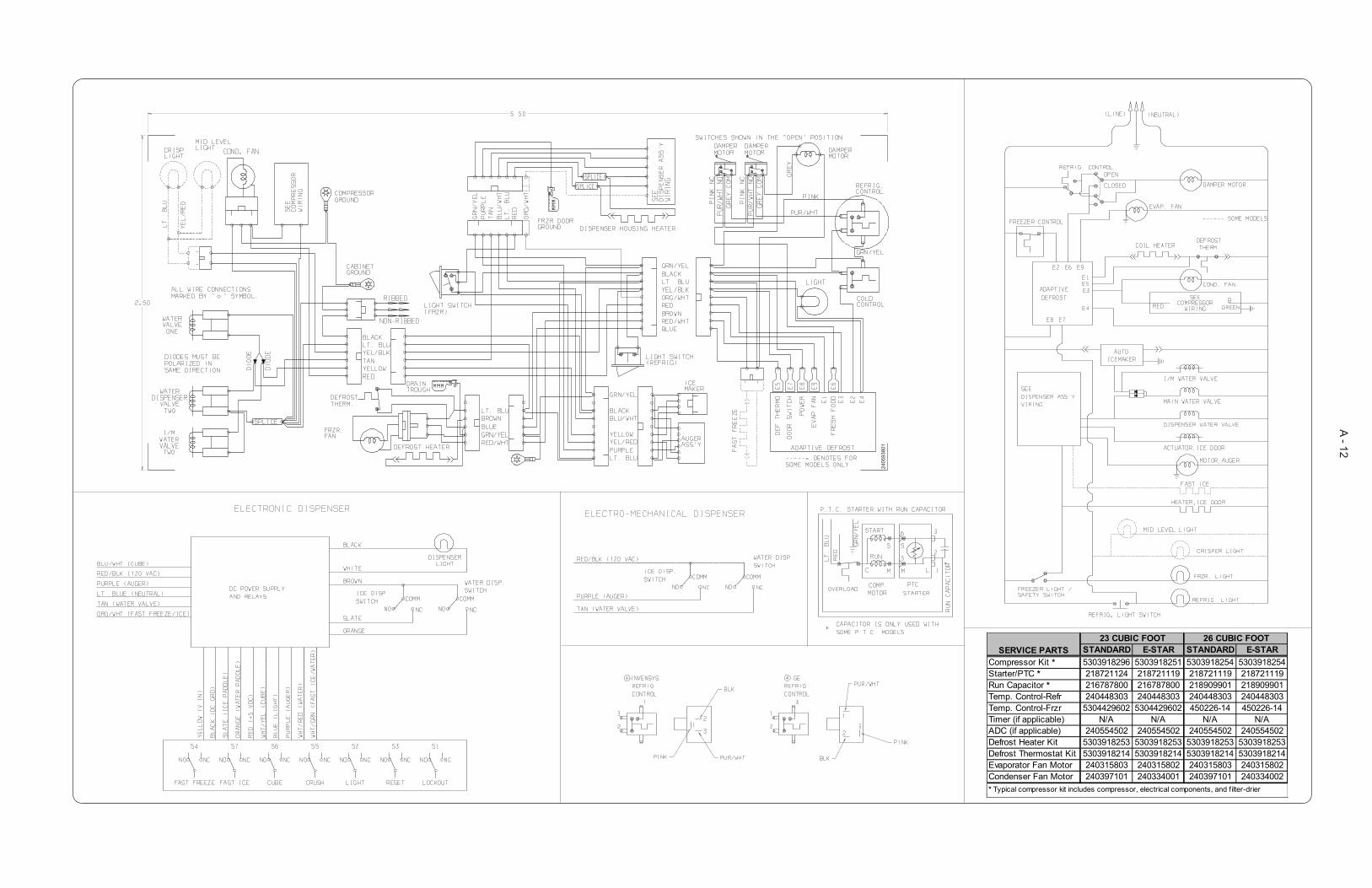
STANDARD E-STAR STANDARD E-STARCompressor Kit * 5303918296 5303918251 5303918254 5303918254Starter/PTC * 218721124 218721119 218721119 218721119Run Capacitor * 216787800 216787800 218909901 218909901Temp. Control-Refr 241507701 241507701 241507701 241507701Temp. Control-Frzr 450226-07 450226-07 450226-07 450226-07Timer (if applicable) N/A N/A N/A N/AADC (if applicable) 241508001 241508001 241508001 241508001Defrost Heater Kit 5303918253 5303918253 5303918253 5303918253Defrost Thermostat Kit 5303918214 5303918214 5303918214 5303918214Evaporator Fan Motor 240315803 240315802 240315803 240315802Condenser Fan Motor 240397101 240334001 240397101 240334002
23 CUBIC FOOT 26 CUBIC FOOT
* Typical compressor kit includes compressor, electrical components, and f ilter-drier
SERVICE PARTS

A - 15
P-3
P-4
P-2P-1GREEN/YELLOW
GREEN/YELLOW
ATADECNAMROFREPGNITTESLORTNOCTNIOP-DIMTASGNINEPOROODONDNADAOLON
roticapaCtratS/nuRhtiWAepyT tneibmA)C°81(F°56 tneibmA)C°23(F°09
emiTgnitarepO %04ot23 %56ot55
erutarepmeTrezeerF F°4ot°0C°61-ot°81-
F°3ot°1-C°61-ot°81-
erutarepmeTrotaregirfeR F°93ot°43C°4ot°1
F°93ot°43C°4ot°1
(erusserPediSwoL )ni-tuc gisp21ot5aPk38ot43
gisp21ot5aPk38ot43
(erusserPediSwoL )tuo-tuc gisp2ot2-aPk41ot41-
gisp2ot2-aPk41ot41-
(erusserPediShgiH )elcycfo3/1tsaL gisp511ot09aPk397ot126
gisp551ot031aPk9601ot698
)elcycfo3/1tsaL(egattaW 051ot021 061ot031
)gninnuR(spmA 5.1ot2.1 5.1ot2.1
egatloVesaB )xamcav721(cav511 )xamcav721(cav511
SNOITACIFICEPSTSORFED
eziStenibaCtatsomrehT retaeH
ni-tuC tuo-tuC sttaW smhO
'62&'32 F°52C°4-
F°74C°8
054 03
.emitnurrosserpmocfosruoh27ot6yrevesetunim42tsorfeD)CDA(-remiTcinortcelE
ROTOMNAFRESNEDNOC
sttaW MPR spmA
7 tfahSetisoppOWC0011 gninnuR1.
SNOITACIFICEPSREKAMECI
lacirtcelE )xamcav721(cav511 ztreH06
tatsomrehT )C°9(F°84tasnepO )C°9-(F°51tasesolC
egattaWretaeH 561
SNOITCENNOCGULPROTCENNOCREKAMECI
rebmuNeriW roloCeriW :otstcennoC
1 wolleY/neerG dnuorG
2 wolleY evlaVretaW
3 kcalB eniL
4 eulB.tL lartueN
SERVICE DATA SHEET - 240389613R134a
ICE & WATER - AUTOMATIC DEFROSTSIDE BY SIDE MODELS
IMPORTANT SAFETY NOTICEThe information provided herein is designed to assist qualifiedrepair personnel only. Untrained persons should not attempt tomake repairs due to the possibility of electrical shock. Disconnectpower cord before servicing.IMPORTANTIf any green grounding wires are moved during servicing, theymust be returned to their original position and properly secured.
NOTE: This product comes equipped with an Electronic DefrostControl. To initiate defrost, depress the fresh food light switch 5times in 6 seconds (light bulb must be working). To terminatedefrost, depress the fresh food light switch 5 times in 6 seconds.
CAUTION: All electrical parts and wiring must be shieldedfrom torch flame. Do not allow torch to contact insulation;it will char at 200°F and flash ignite (burn) at 500°F. Excessiveheat will distort the plastic liner.
ICE MAKER INFORMATION
Test Cycling
Remove cover by inserting screwdriver in notch at bottomand prying cover from housing. Use screwdriver to rotate motorgear counterclockwise until holding switch circuit is completed.All components of ice maker should function to complete thecycle.
Water Fill Volume
The water fill adjustment screw will change the fill time. One fullturn is equal to 20cc (.68 oz.). The correct fill is 102 to 130cc(3.4 to 4.3 oz.). When a water valve is replaced, the fill volumemust be checked.
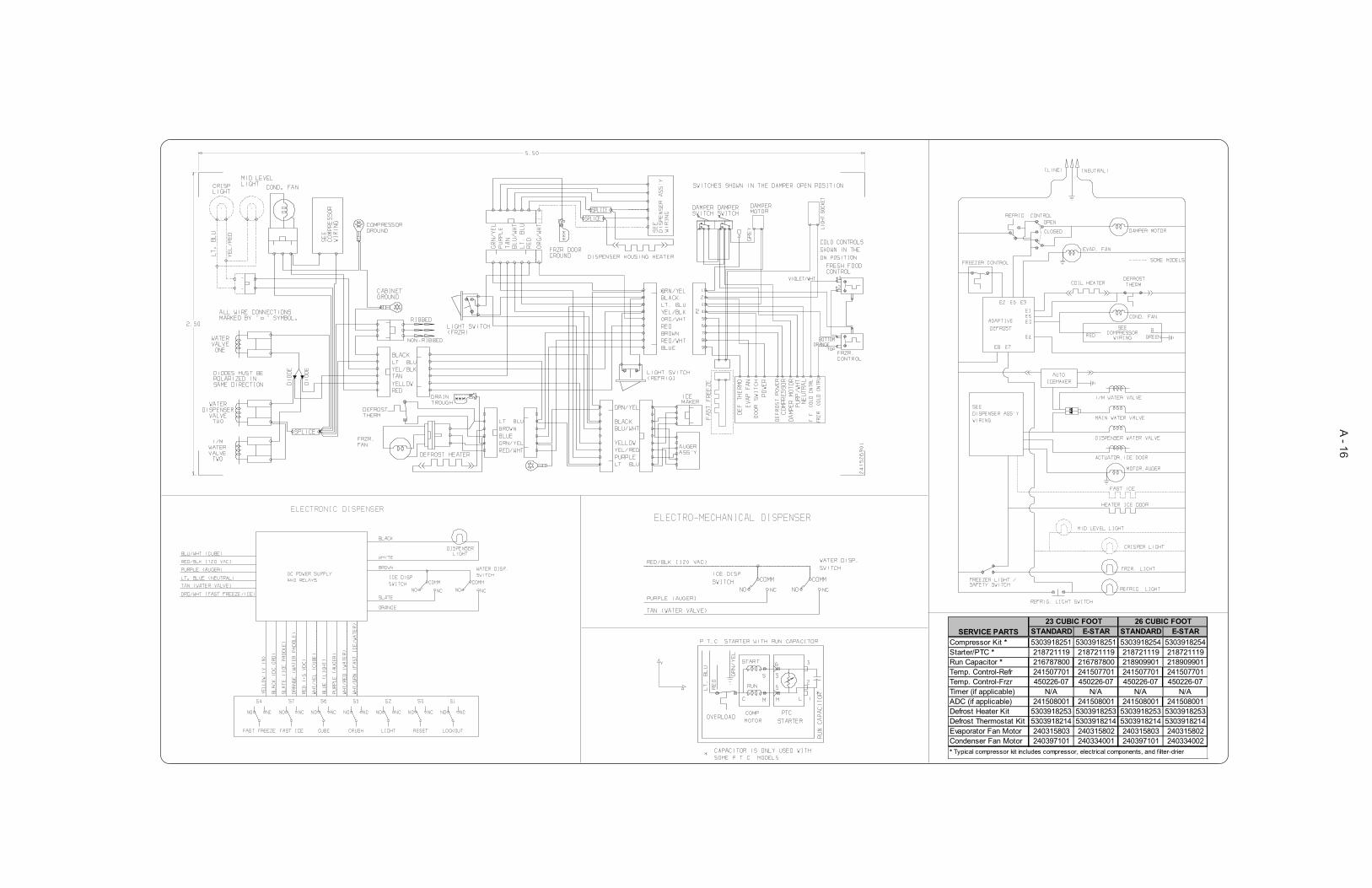
A - 16
STANDARD E-STAR STANDARD E-STARCompressor Kit * 5303918251 5303918251 5303918254 5303918254Starter/PTC * 218721119 218721119 218721119 218721119Run Capacitor * 216787800 216787800 218909901 218909901Temp. Control-Refr 241507701 241507701 241507701 241507701Temp. Control-Frzr 450226-07 450226-07 450226-07 450226-07Timer (if applicable) N/A N/A N/A N/AADC (if applicable) 241508001 241508001 241508001 241508001Defrost Heater Kit 5303918253 5303918253 5303918253 5303918253Defrost Thermostat Kit 5303918214 5303918214 5303918214 5303918214Evaporator Fan Motor 240315803 240315802 240315803 240315802Condenser Fan Motor 240397101 240334001 240397101 240334002
23 CUBIC FOOT 26 CUBIC FOOT
* Typical compressor kit includes compressor, electrical components, and filter-drier
SERVICE PARTS

A - 17
ATADECNAMROFREPGNITTESLORTNOCTNIOP-DIMTASGNINEPOROODONDNADAOLON
roticapaCtratS/nuRhtiWAepyT tneibmA)C°81(F°56 tneibmA)C°23(F°09
emiTgnitarepO %04ot23 %56ot55
erutarepmeTrezeerF F°4ot°0C°61-ot°81-
F°3ot°1-C°61-ot°81-
erutarepmeTrotaregirfeR F°93ot°43C°4ot°1
F°93ot°43C°4ot°1
(erusserPediSwoL )ni-tuc gisp21ot5aPk38ot43
gisp21ot5aPk38ot43
(erusserPediSwoL )tuo-tuc gisp2ot2-aPk41ot41-
gisp2ot2-aPk41ot41-
(erusserPediShgiH )elcycfo3/1tsaL gisp511ot09aPk397ot126
gisp551ot031aPk9601ot698
)elcycfo3/1tsaL(egattaW 051ot021 061ot031
)gninnuR(spmA 5.1ot2.1 5.1ot2.1
egatloVesaB )xamcav721(cav511 )xamcav721(cav511
SNOITACIFICEPSTSORFED
eziStenibaCtatsomrehT retaeH
ni-tuC tuo-tuC sttaW smhO
'62&'32 F°52C°4-
F°74C°8
054 03
.emitnurrosserpmocfosruoh27ot6yrevesetunim42tsorfeD)CDA(-remiTcinortcelE
ROTOMNAFRESNEDNOC
sttaW MPR spmA
7 tfahSetisoppOWC0011 gninnuR1.
SNOITACIFICEPSREKAMECI
lacirtcelE )xamcav721(cav511 ztreH06
tatsomrehT )C°9(F°84tasnepO )C°9-(F°51tasesolC
egattaWretaeH 561
SNOITCENNOCGULPROTCENNOCREKAMECI
rebmuNeriW roloCeriW :otstcennoC
1 wolleY/neerG dnuorG
2 wolleY evlaVretaW
3 kcalB eniL
4 eulB.tL lartueN
SERVICE DATA SHEET - 240389614R134a
ICE & WATER - AUTOMATIC DEFROSTSIDE BY SIDE MODELS
IMPORTANT SAFETY NOTICEThe information provided herein is designed to assist qualifiedrepair personnel only. Untrained persons should not attempt tomake repairs due to the possibility of electrical shock. Disconnectpower cord before servicing.IMPORTANTIf any green grounding wires are moved during servicing, theymust be returned to their original position and properly secured.
NOTE: This product comes equipped with an Electronic DefrostControl. To initiate defrost, depress the fresh food light switch 5times in 6 seconds (light bulb must be working). To terminatedefrost, depress the fresh food light switch 5 times in 6 seconds.
CAUTION: All electrical parts and wiring must be shieldedfrom torch flame. Do not allow torch to contact insulation;it will char at 200°F and flash ignite (burn) at 500°F. Excessiveheat will distort the plastic liner.
P-3
P-4
P-2P-1GREEN/YELLOW
GREEN/YELLOW
ICE MAKER INFORMATION
Test Cycling
Remove cover by inserting screwdriver in notch at bottomand prying cover from housing. Use screwdriver to rotate motorgear counterclockwise until holding switch circuit is completed.All components of ice maker should function to complete thecycle.
Water Fill Volume
The water fill adjustment screw will change the fill time. One fullturn is equal to 20cc (.68 oz.). The correct fill is 102 to 130cc(3.4 to 4.3 oz.). When a water valve is replaced, the fill volumemust be checked.

A - 18
STANDARD E-STAR STANDARD E-STARCompressor Kit * 5303918251 5303918251 5303918254 5303918254Starter/PTC * 218721119 218721119 218721119 218721119Run Capacitor * 216787800 216787800 218909901 218909901Temp. Control-Refr 241507701 241507701 241507701 241507701Temp. Control-Frzr 450226-07 450226-07 450226-07 450226-07Timer (if applicable) N/A N/A N/A N/AADC (if applicable) 241508001 241508001 241508001 241508001Defrost Heater Kit 5303918253 5303918253 5303918253 5303918253Defrost Thermostat Kit 5303918214 5303918214 5303918214 5303918214Evaporator Fan Motor 240315803 240315802 240315803 240315802Condenser Fan Motor 240397101 240334001 240397101 240334002
23 CUBIC FOOT 26 CUBIC FOOT
* Typical compressor kit includes compressor, electrical components, and f ilter-drier
SERVICE PARTS
A - 19
ATADECNAMROFREPGNITTESLORTNOCTNIOP-DIMTASGNINEPOROODONDNADAOLON
roticapaCtratS/nuRhtiWAepyT tneibmA)C°81(F°56 tneibmA)C°23(F°09
emiTgnitarepO %04ot23 %56ot55
erutarepmeTrezeerF F°4ot°0C°61-ot°81-
F°3ot°1-C°61-ot°81-
erutarepmeTrotaregirfeR F°93ot°43C°4ot°1
F°93ot°43C°4ot°1
(erusserPediSwoL )ni-tuc gisp21ot5aPk38ot43
gisp21ot5aPk38ot43
(erusserPediSwoL )tuo-tuc gisp2ot2-aPk41ot41-
gisp2ot2-aPk41ot41-
(erusserPediShgiH )elcycfo3/1tsaL gisp511ot09aPk397ot126
gisp551ot031aPk9601ot698
)elcycfo3/1tsaL(egattaW 051ot021 061ot031
)gninnuR(spmA 5.1ot2.1 5.1ot2.1
egatloVesaB )xamcav721(cav511 )xamcav721(cav511
SNOITACIFICEPSTSORFED
eziStenibaCtatsomrehT retaeH
ni-tuC tuo-tuC sttaW smhO
'62&'32 F°52C°4-
F°74C°8
054 03
.emitnurrosserpmocfosruoh27ot6yrevesetunim42tsorfeD)CDA(-remiTcinortcelE
ROTOMNAFRESNEDNOC
sttaW MPR spmA
7 tfahSetisoppOWC0011 gninnuR1.
SNOITACIFICEPSREKAMECI
lacirtcelE )xamcav721(cav511 ztreH06
tatsomrehT )C°9(F°84tasnepO )C°9-(F°51tasesolC
egattaWretaeH 561
SNOITCENNOCGULPROTCENNOCREKAMECI
rebmuNeriW roloCeriW :otstcennoC
1 wolleY/neerG dnuorG
2 wolleY evlaVretaW
3 kcalB eniL
4 eulB.tL lartueN
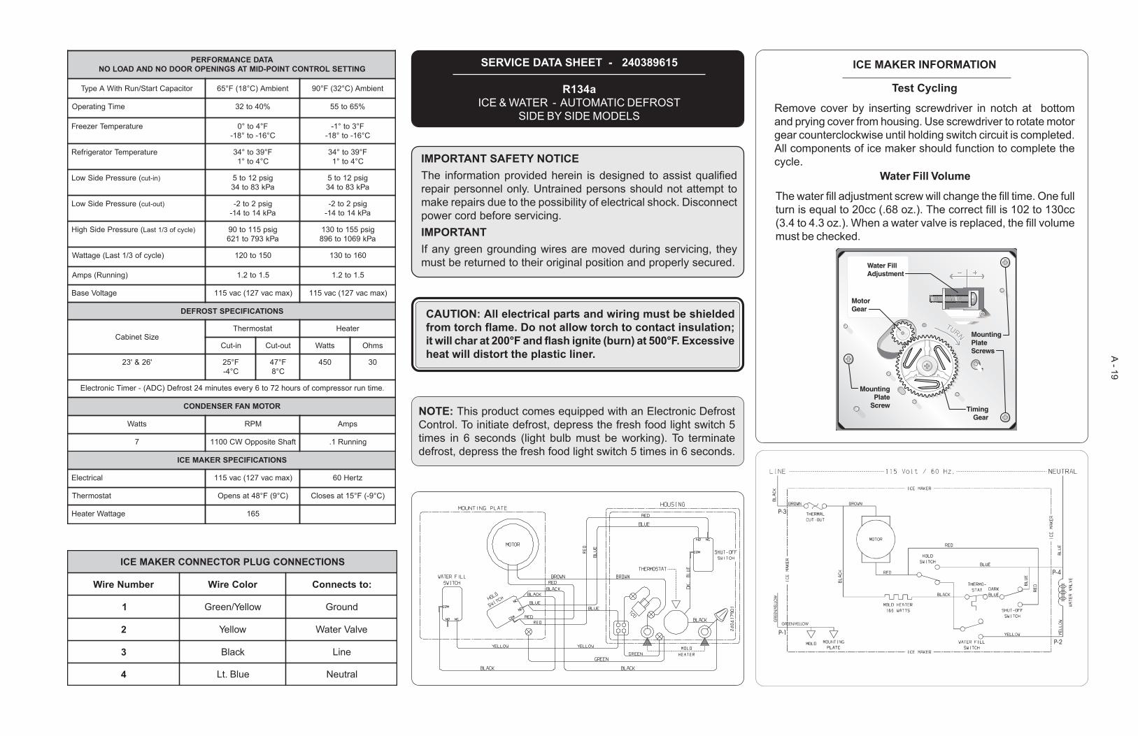
SERVICE DATA SHEET - 240389615
R134aICE & WATER - AUTOMATIC DEFROST
SIDE BY SIDE MODELS
IMPORTANT SAFETY NOTICEThe information provided herein is designed to assist qualifiedrepair personnel only. Untrained persons should not attempt tomake repairs due to the possibility of electrical shock. Disconnectpower cord before servicing.IMPORTANTIf any green grounding wires are moved during servicing, theymust be returned to their original position and properly secured.
NOTE: This product comes equipped with an Electronic DefrostControl. To initiate defrost, depress the fresh food light switch 5times in 6 seconds (light bulb must be working). To terminatedefrost, depress the fresh food light switch 5 times in 6 seconds.
CAUTION: All electrical parts and wiring must be shieldedfrom torch flame. Do not allow torch to contact insulation;it will char at 200°F and flash ignite (burn) at 500°F. Excessiveheat will distort the plastic liner.
P-3
P-4
P-2P-1GREEN/YELLOW
GREEN/YELLOW
ICE MAKER INFORMATION
Test Cycling
Remove cover by inserting screwdriver in notch at bottomand prying cover from housing. Use screwdriver to rotate motorgear counterclockwise until holding switch circuit is completed.All components of ice maker should function to complete thecycle.
Water Fill Volume
The water fill adjustment screw will change the fill time. One fullturn is equal to 20cc (.68 oz.). The correct fill is 102 to 130cc(3.4 to 4.3 oz.). When a water valve is replaced, the fill volumemust be checked.
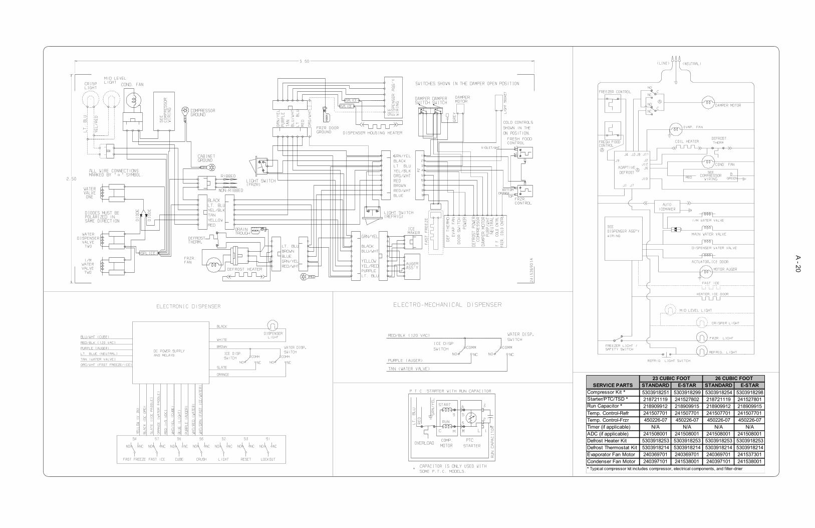
A - 20
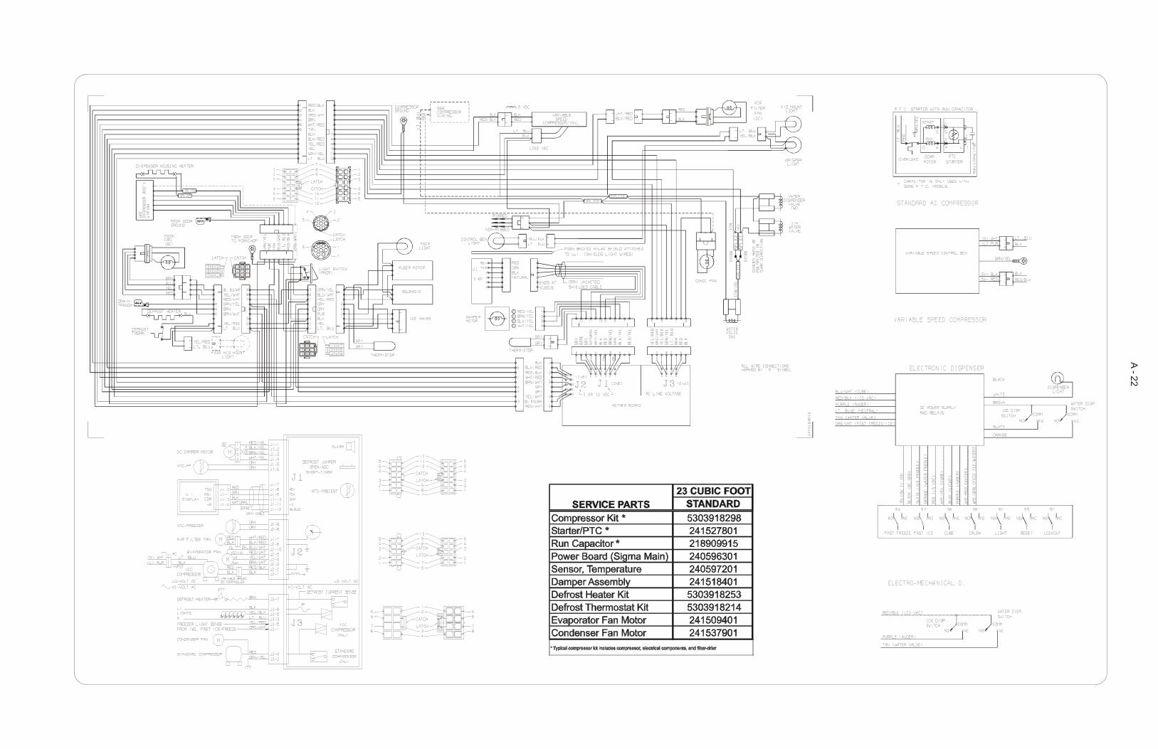
STANDARD E-STAR STANDARD E-STARCompressor Kit * 5303918251 5303918299 5303918254 5303918298Starter/PTC/TSD * 218721119 241527802 218721119 241527801Run Capacitor * 218909912 218909915 218909912 218909915Temp. Control-Refr 241507701 241507701 241507701 241507701Temp. Control-Frzr 450226-07 450226-07 450226-07 450226-07Timer (if applicable) N/A N/A N/A N/AADC (if applicable) 241508001 241508001 241508001 241508001Defrost Heater Kit 5303918253 5303918253 5303918253 5303918253Defrost Thermostat Kit 5303918214 5303918214 5303918214 5303918214Evaporator Fan Motor 240369701 240369701 240369701 241537301Condenser Fan Motor 240397101 241538001 240397101 241538001
23 CUBIC FOOT 26 CUBIC FOOT
* Typical compressor kit includes compressor, electrical components, and filter-drier
SERVICE PARTS
A - 21
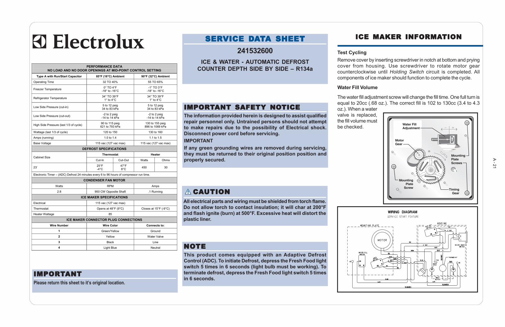
IMPORIMPORIMPORIMPORIMPORTTTTTANT SAFETY NOANT SAFETY NOANT SAFETY NOANT SAFETY NOANT SAFETY NOTICETICETICETICETICEThe information provided herein is designed to assist qualifiedrepair personnel only. Untrained persons should not attemptto make repairs due to the possibility of Electrical shock.Disconnect power cord before servicing.IMPORTANTIf any green grounding wires are removed during servicing,they must be returned to their original position position andproperly secured.
! CACACACACAUTIONUTIONUTIONUTIONUTIONAll electrical parts and wiring must be shielded from torch flame.Do not allow torch to contact insulation; it will char at 200°Fand flash ignite (burn) at 500°F. Excessive heat will distort theplastic liner.
NONONONONOTETETETETEThis product comes equipped with an Adaptive DefrostControl (ADC). To initiate Defrost, depress the Fresh Food lightswitch 5 times in 6 seconds (light bulb must be working). Toterminate defrost, depress the Fresh Food light switch 5 timesin 6 seconds.
SERSERSERSERSERVICE DVICE DVICE DVICE DVICE DAAAAATTTTTA SHEETA SHEETA SHEETA SHEETA SHEET241532600
ICE & WATER - AUTOMATIC DEFROSTCOUNTER DEPTH SIDE BY SIDE – R134a
ICE MAKER INFORMAICE MAKER INFORMAICE MAKER INFORMAICE MAKER INFORMAICE MAKER INFORMATIONTIONTIONTIONTION
Test CyclingRemove cover by inserting screwdriver in notch at bottom and pryingcover from housing. Use screwdriver to rotate motor gearcounterclockwise until Holding Switch circuit is completed. Allcomponents of ice maker should function to complete the cycle.
Water Fill Volume
The water fill adjustment screw will change the fill time. One full turn isequal to 20cc (.68 oz.). The correct fill is 102 to 130cc (3.4 to 4.3oz.). When a watervalve is replaced,the fill volume mustbe checked.
IMPORIMPORIMPORIMPORIMPORTTTTTANTANTANTANTANTPlease return this sheet to it’s original location.
PERFORMANCE DATA NO LOAD AND NO DOOR OPENINGS AT MID-POINT CONTROL SETTING
Type A with Run/Start Capacitor 85°F (18°C) Ambient 90°F (32°C) Ambient
Operating Time 32 TO 40% 55 TO 65%
Freezer Temperature 0° TO 4°F -18° to -16°C
-1° TO 3°F -18° to -16°C
Refrigerator Temperature 34° TO 39°F 1° to 4°C
34° TO 39°F 1° to 4°C
Low Side Pressure (cut-in) 5 to 12 psig 34 to 83 kPa
5 to 12 psig 34 to 83 kPa
Low Side Pressure (cut-out) -2 to 2 psig -14 to 14 kPa
-2 to 2 psig -14 to 14 kPa
High Side Pressure (last 1/3 of cycle) 90 to 115 psig 621 to 793 kPa
130 to 155 psig 896 to 1069 kPa
Wattage (last 1/3 of cycle) 120 to 150 130 to 160
Amps (running) 1.0 to 1.4 1.1 to 1.5
Base Voltage 115 vac (127 vac max) 115 vac (127 vac max)
DEFROST SPECIFICATIONS Thermostat Heater
Cabinet Size Cut-In Cut-Out Watts Ohms
23’ 25°F -4°C
47°F 8°C 450 30
Electronic Timer – (ADC) Defrost 24 minutes every 6 to 96 hours of compressor run time.
CONDENSER FAN MOTOR
Watts RPM Amps
2.8 950 CW Opposite Shaft .1 Running
ICE MAKER SPECIFICATIONS Electrical 115 vac (127 vac max)
Thermostat Opens at 48°F (9°C) Closes at 15°F (-9°C)
Heater Wattage 85
ICE MAKER CONNECTOR PLUG CONNECTIONS Wire Number Wire Color Connects to:
1 Green/Yellow Ground
2 Yellow Water Valve
3 Black Line
4 Light Blue Neutral
A - 22