product index asset library/fluid control-chapb-2_2... · -10°c to +90°c nbr (nitrile) steam up...
TRANSCRIPT
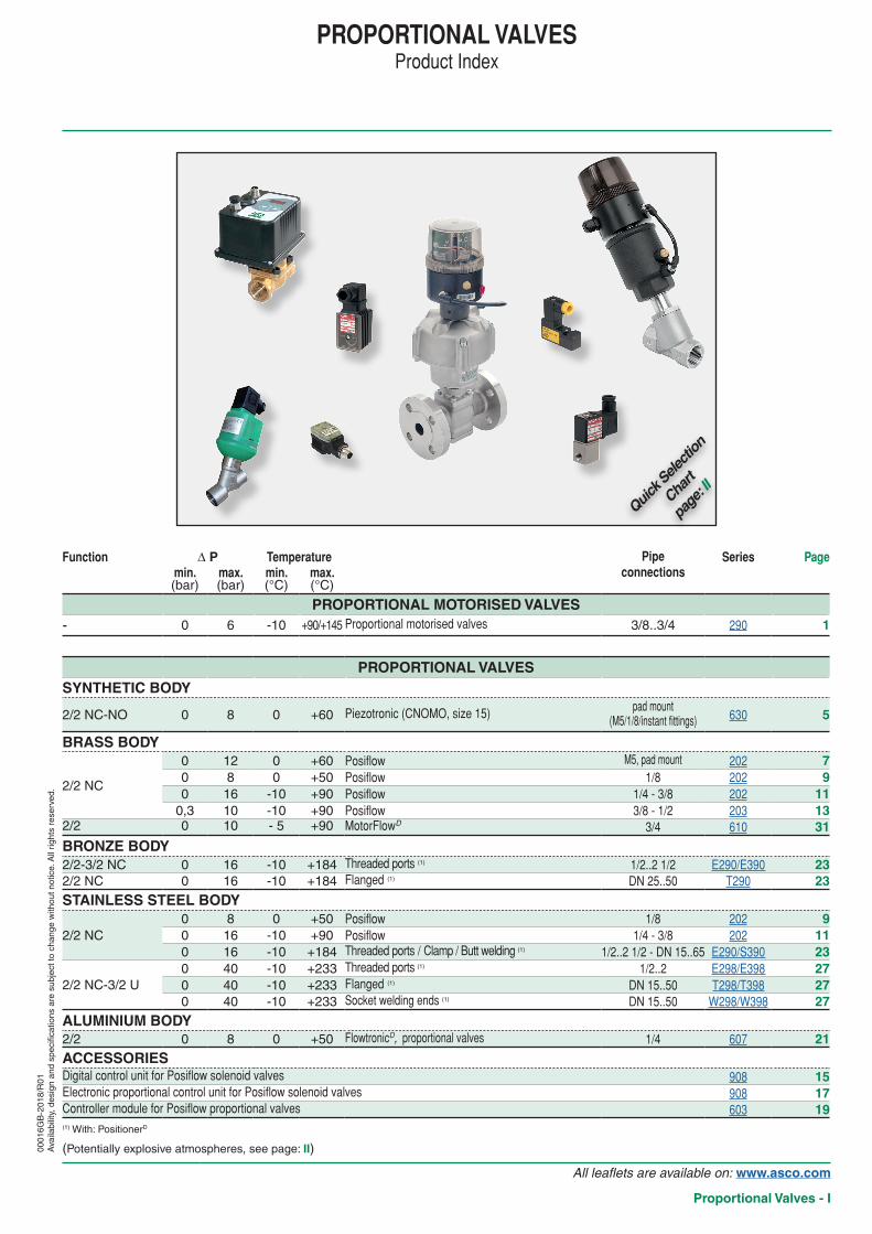
PROPORTIONAL VALVESProduct Index
(Potentially explosive atmospheres see page II)
Function ∆ P Temperature Pipeconnections
Series Pagemin max min max(bar) (bar) (degC) (degC)
PROPORTIONAL MOTORISED VALVES- 0 6 -10 +90+145 Proportional motorised valves 3834 290 1
PROPORTIONAL VALVESSYNTHETIC BODY
22 NC-NO 0 8 0 +60 Piezotronic (CNOMO size 15) pad mount(M518instant fittings) 630 5
BRASS BODY
22 NC
0 12 0 +60 Posiflow M5 pad mount 202 70 8 0 +50 Posiflow 18 202 90 16 -10 +90 Posiflow 14 - 38 202 11
03 10 -10 +90 Posiflow 38 - 12 203 1322 0 10 - 5 +90 MotorFlowD 34 610 31
BRONZE BODY22-32 NC 0 16 -10 +184 Threaded ports (1) 122 12 E290E390 2322 NC 0 16 -10 +184 Flanged (1) DN 2550 T290 23
STAINLESS STEEL BODY
22 NC0 8 0 +50 Posiflow 18 202 90 16 -10 +90 Posiflow 14 - 38 202 110 16 -10 +184 Threaded ports Clamp Butt welding (1) 122 12 - DN 1565 E290S390 23
22 NC-32 U0 40 -10 +233 Threaded ports (1) 122 E298E398 270 40 -10 +233 Flanged (1) DN 1550 T298T398 270 40 -10 +233 Socket welding ends (1) DN 1550 W298W398 27
ALUMINIUM BODY22 0 8 0 +50 FlowtronicD proportional valves 14 607 21ACCESSORIESDigital control unit for Posiflow solenoid valves 908 15Electronic proportional control unit for Posiflow solenoid valves 908 17Controller module for Posiflow proportional valves 603 19(1) With PositionerD
0001
6GB
-201
8R
01A
vaila
bilit
y d
esig
n an
d sp
ecifi
catio
ns a
re s
ubje
ct to
cha
nge
with
out n
otic
e A
ll rig
hts
rese
rved
All leaflets are available on wwwascocom
Proportional Valves - I
Quick S
electi
on
Chart
page
II
pipe connectionsw - internal thread n - pad mountl - flanged v - clampc - butt weldings - pad mount CNOMO size 15
body materials
orifi
ce s
ize
(mm
)
DN
min
ope
ratin
g pr
essu
re
diffe
rent
ial(b
ar)
max operating pressure differential
(bar)
max
allo
wab
le
pres
sure
(bar
)
fluid temperature
range
pow
er c
oil
serie
s
IampM
She
et
page
DC(=)
- 10
- 15
- 20
- 25
- 32
- 40
- 50
- 65
pad
mou
ntbr
onze
bras
sal
umin
ium
synt
hetic
stai
nles
s st
eel
st st
eel A
ISI 3
16L
all A
ISI 3
16L
air
iner
t gas
esw
ater
oil
vacu
umai
r in
ert g
ases
aggr
essiv
e flu
idsai
r in
ert g
ases
aggr
essiv
e liq
uids
vacu
umho
t wat
erste
am le
145deg
Cste
am le
184deg
C (degC) (W)
M5
18
14
38
12
34
1 1 1
41
12
2 2 1
2
min
maxDC(=) m
ax DC
(=)
PROPORTIONAL MOTORISED VALVES
w w w y10uuml20
06uuml4
10-2 - - - - - - 4 - 10 -10 +90 +145 14 290 1
22 SOLENOID VALVES - NORMALLY CLOSED (NC)
w s y - - 0 8 - - - - - - - - - 0 +60 - 0004 630 54 - - - - - - - - -
w n y08 - 0 12 - 1 - - - - - - -
- 0 +60 - 26 202 72 - 0 25 - 1 - - - - - - -
w y y 12 - 0 8 5 1 - - - - - - - - 0 +50 - 63 202 932 - 0 2525 1 - - - - - - - -
w y y12 - 0 16 16 1 - - - - - - - -
-10 +90 - 8 202 1171 - 0 1 1 1 - - - - - - - -
w y y 32 - 0 4 4 1 - - - - - - - -71 - 0 1 1 1 - - - - - - - -
w w y 125 - 03 - 10 - - - - - - - - - -10 +90 - 8 203 13MOTORISED CONTROL VALVE 22 - MotorFlowD
w y 15 - 0 10 10 -09 - - - - - - - - -5 +90 - 10 610 3122 SOLENOID VALVES - NORMALLY OPEN (NO)
w s y - - 0 8 - - - - - - - - - 0 +60 - 0004 630 54 - - - - - - - - -22 VALVES - NORMALLY CLOSED (NC) - FLOWTRONICD POSITIONERD
w y 6 0 8 - - - - - - - - - 8 0 - +50 607 21w w w w w w w y y y
15uuml65
0 - - -16uuml10
10-2
mbar 16
uuml10
10 16 -10 - +184 -
E290
23v v v v v v v
y y 0 - - - S290c c c c c c c
l l l l y25uuml50
0 - - -16uuml10
-16uuml10
- T290
w w w w w w y 15uuml65
0 - - - - - - - - - - - 40 -10 - +233 -E298
27l l l l l l y T298c c c c c c y W298
32 VALVES - NORMALLY CLOSED (NC) - POSITIONERD
w w w w w w y15uuml50
0 - - -16uuml10
-16uuml10
- -16uuml10
10 16 -10 - +184 - E390 23
32 VALVES - UNIVERSAL (U) - POSITIONERD
w w w w w w y 15uuml65
0 - - - - - - - - - - - 40 -10 - +233 -E298
27l l l l l l y T298c c c c c c y W298
Quick Selection Chart - PROPORTIONAL VALVES
q
ope
rato
rs(S
ee s
ectio
n
Expl
osio
npro
of
equi
pmen
t)
group IIgas dusts
zones2 - 22
zones1 - 21
zones0 - 20
3 GDEx nA
2 G Ex db2 D Ex tb
2 G Ex eb mb2 D Ex tb
2 G Ex mb2 D Ex mb
page
serie
s
power coil(W)
EM (M
XX)
WSE
M (M
XX)
PV (E
MXX
)
DC
(=)
7 202 269 202 6311 202 813 203 8 (1) (1) (1)
(1) Contact us
0001
6GB
-201
8R
02A
vaila
bilit
y d
esig
n an
d sp
ecifi
catio
ns a
re s
ubje
ct to
cha
nge
with
out n
otic
e A
ll rig
hts
rese
rved
All leaflets are available on wwwascocom
II - Proportional Valves
All leaflets are available on wwwascocom
Proportional Valves (Proportional motorised valves) - 1
FEATURESbull Long service lifebull Variable flow proportional to the control signalbull Ready-to-use valvebull High flow due to angled seat designbull Anti-waterhammer design (fluid entry under the disc)bull Actuator rotatable through 360degbull In option closing of the valve in case of power failurebull Fluid isolation between motorised actuator and valve bodybull LED indicators for valve status displaybull Valve tight at closing position (FCI 70-2 class V)bull Vacuum operation up to 10-2 mbarbull The valves satisfy Pressure Equipment Directive 201464EU article 43bull The proportional motorised valves comply with the essential requirements of EMC
Directive 201430EU (EN-IEC 61000-6-2 et EN-IEC 61000-6-4)bull The valves satisfy all relevant EU Directives and with the provisions of the Directive
RoHS 2
CONSTRUCTION Differential pressure See laquoSPECIFICATIONSraquo [1 bar =100 kPa]Maximum allowable pressure 10 barAmbient temperature range -10degC to +50degC
-10degC to +40degC (for steam at 145degC)Maximum viscosity 600 cSt (mm2s)Actuating time lt 13 s (full opening)
lt 13 s (full closing)fluids () temperature range (TS) seal materials ()
air and gas groups 1 amp 2water oil liquids groups 1 amp 2 -10degC to +90degC NBR (nitrile)
steam up to +145degC FPM (fluoroelastomer)
CONSTRUCTIONMATERIALS IN CONTACT WITH FLUID
() Ensure that the compatibility of the fluids in contact with the materials is verified
NBR PBTlaquoKraquo
FPM 316LlaquoXraquo
Valve body AISI 316L AISI 316LStuffing box housing PBT GF reinforced AISI 316LStem valve AISI 316L AISI 316LStuffing box packing NBR FPMWiper seal NBR FPMDisc seal NBR FPM
OTHER MATERIALSTop cover operator Translucent polyamide (PA)
ELECTRICAL CHARACTERISTICSConnector Spade plug (cable Oslash 6-10 mm)Connector specification ISO 4400 EN 175301-803 form A
Motor consumption12 W in operation lt 2 W holding phaseset point positionMax peak current 07 A
Visualisation valve (switching) LEDElectrical enclosure protection IP65 (EN 60529)Standard voltages DC (=) 24V plusmn10 max ripple 5Setpoint 0-10 V (input resistance = 10 kΩ)
4-20 mA (input resistance = 500 Ω)
Flow regulation characteristics Linearity plusmn5 hysteresis lt 5 accuracy lt3 sensitivity lt 3 repeatability lt3
() Ensure that the compatibility of the fluids in contact with the materials is verified(1) Contact us
PROPORTIONAL MOTORISED VALVES
stainless steel bodythreaded ports 38 - 12 - 34
1
2
2 waySeries
290
12
360deg
0102
0GB
-201
8R
01A
vaila
bilit
y d
esig
n an
d sp
ecifi
catio
ns a
re s
ubje
ct to
cha
nge
with
out n
otic
e A
ll rig
hts
rese
rved
setpoint( ) Recommended
working area
Flo
w
0 10010 90
( )
All leaflets are available on wwwascocom
2 - Proportional Valves (Proportional motorised valves)
PROPORTIONAL MOTORISED VALVES SERIES 290
SPECIFICATIONS 15-DIGIT PRODUCT CODEpiping
(ISO 6708) flowcoefficient
Kvs(100 opening)
operating pressuredifferential (bar)
operatordiameter
thre
ad
type
dim
ensi
ons
ty
pe (2
)
basic code
voltage code
24 V
DC
pipesize
DN min
max
air water oil()
steam(m3h) (lmin) (mm)
Motorised valve entry under the disc (4-20 mA) - NBR PBT laquoKraquo version38 10 27 45 0 6 - 67 G 1 E290CP2V0K4MA
V112 15 38 63 0 5 - 67 G 1 E290CP3V0K4MA34 20 6 100 0 4 - 67 G 1 E290CP4V0K4MA
Motorised valve entry under the disc (0-10 V) - NBR PBT laquoKraquo version38 10 27 45 0 6 - 67 G 1 E290CP2V0K00V
V112 15 38 63 0 5 - 67 G 1 E290CP3V0K00V34 20 6 100 0 4 - 67 G 1 E290CP4V0K00V
Motorised valve entry under the disc (4-20 mA) - FPM 316L laquoXraquo version38 10 27 45 0 6 4 67 G 1 E290CP2V0X4MA
V112 15 38 63 0 5 4 67 G 1 E290CP3V0X4MA34 20 6 100 0 4 4 67 G 1 E290CP4V0X4MA
Motorised valve entry under the disc (0-10 V) - FPM 316L laquoXraquo version38 10 27 45 0 6 4 67 G 1 E290CP2V0X00V
V112 15 38 63 0 5 4 67 G 1 E290CP3V0X00V34 20 6 100 0 4 4 67 G 1 E290CP4V0X00V
(2) For dimensions see drawing(s) for each construction type on the following page(s)() Ensure that the compatibility of the fluids in contact with the materials is verified
0102
0GB
-201
8R
02A
vaila
bilit
y d
esig
n an
d sp
ecifi
catio
ns a
re s
ubje
ct to
cha
nge
with
out n
otic
e A
ll rig
hts
rese
rved
OPTIONSFail closed (closing of the valve in case of power failure)
4 cyclesmin
9 cyclesmin
2 cyclesmin
2 cyclesmin
+120Cdeg
-10Cdeg
+50Cdeg
+20Cdeg
+145Cdeg
-20-10
01020304050608090
100110120130140150
-100102030405060708090100110120130140150160170180190200210220230240250260270280
FdegCdeg
-20-10
010203040506070
-100
102030405060708090
100110120130140150160
Fdeg Cdeg
+50Cdeg
-10Cdeg
+20Cdeg
+40Cdeg
NBR PBT laquoKraquo version
-20-10
010203040506070
-100
102030405060708090
100110120130140150160
Fdeg Cdeg
+50Cdeg
9 cyclesmin
4 cyclesmin
+20Cdeg
OP
ER
AT
ING
CO
ND
ITIO
NS
RE
CO
MM
EN
DA
TIO
N F
OR
MA
XIM
UM
DU
TY
CY
CL
E
FPM 316L laquoXraquo version
ambi
ent t
empe
ratu
re
ambi
ent t
empe
ratu
re
max
All leaflets are available on wwwascocom
Proportional Valves (Proportional motorised valves) - 3
INSTALLATIONbull The valves can be mounted in any position without affecting operationbull Pipe connections (G) have standard combination thread according to ISO 2281 and ISO 71bull Other pipe connections are available on requestbull Installationmaintenance instructions are included with each valvebull LED indicators for operating status display
stat
us
valve OPEN greenvalve CLOSED orangevalve moves to open green flashingvalve moves to close green flashing
PROPORTIONAL MOTORISED VALVES SERIES 29001
020G
B-2
018
R02
Ava
ilabi
lity
des
ign
and
spec
ifica
tions
are
sub
ject
to c
hang
e w
ithou
t not
ice
All
right
s re
serv
ed
15-DIGIT PRODUCT CODEE 290 C P 4 V 0 K 4MA V1
Pipe thread VoltageE = ISO 2281 amp ISO 71 (combination thread) V1 = 24 V DC - class B8 = NPT (on request)
Product series290
Revision letter 4MA = 4-20 mA - SetpointC = Initial release 00V = 0-10 V - Setpoint
FC4 = EFC + 4-20 mA (1)
FC0 = EFC + 0-10 V (2)
FonctionP = Proportional
MaterialsDN K = AISI 316L body
SS 316L stem PBT stuffing box amp NBR
2 = DN 103 = DN 154 = DN 20 X = AISI 316L body
SS 316L stem AISI 316L stuffing box amp FPM
PortMotorised operator dia 0 = 2 wayV = Oslash 67 mm
(1) Closing of the valve in case of power failure Set point 4-20 mA(2) Closing of the valve in case of power failure Set point 0-10 V
Configurator - CAD Files
All leaflets are available on wwwascocom
4 - Proportional Valves (Proportional motorised valves)
PROPORTIONAL MOTORISED VALVES SERIES 290
0102
0GB
-201
8R
02A
vaila
bilit
y d
esig
n an
d sp
ecifi
catio
ns a
re s
ubje
ct to
cha
nge
with
out n
otic
e A
ll rig
hts
rese
rved
WIRING DC24 V plusmn10 DC
4
1
2
3 1 24 V DC
2 0 V
3 setpoint (0-10 V or 4-20 mA)
4 feedback signal(24 V switch)
DIMENSIONS (mm) WEIGHT (kg)
TYPE 01DC version67 mm motorised operatorFluid entry under the disc at 2ISO 4400 connector
C
OslashF
OslashA
D
EB
50deg
1 2
360deg
Position laquobraquo
t0
Position laquoaraquo
setpoint
state return
type Oslash A B C D E Oslash Fweight (1)
NBR PBT laquoKraquo FPM 316L laquoXraquo
DC version
0138 135 141 129 55 67 040 04512 142 145 131 65 67 045 05534 150 152 136 75 67 055 065
(1) Incl connector
V supply
Configurator - CAD Files
FEATURESbull Miniature ultra-low power consumption (0004 W) almost no heat dissipationbull Pad mounting proportional mini piezo-valves available with single subbase M5bull Variable flow proportional to the control signalbull No wearing parts practically unlimited service lifebull No inductive peaks when switching no circuit protection necessarybull Valves do not require a minimum operating pressurebull The solenoid valves satisfy all relevant EU directives
GENERALDifferential pressure See laquoSPECIFICATIONSraquo [1 bar = 100 kPa]Pneumatic base ISO 15218 (CNOMO E0636120N size 15)Response time 8 - 15 ms
fluids () temperature range (TS) seal materials ()
air inert gasfiltered at 5 microm unlubricatedcondensate free dew point -10degC
0degC to +60degC NBR (nitrile)
MATERIALS IN CONTACT WITH FLUID() Ensure that the compatibility of the fluids in contact with the materials is verifiedBody PPSInternal parts Piezo ceramics brassSeals NBRSubbases Brass or aluminium
ELECTRICAL CHARACTERISTICSConnector Spade plug (cable Oslash 6-7 mm)Connector specification DIN 43650 94 mm form C or 2 leads outlet AWG 28 length 1 mElectrical safety IEC 335Electrical enclosure protection Moulded IP65 (EN 60529)Standard voltages (UN) DC (=) 0 to 40 V
holding current
power ratings ambient temperature range
(TS) type (1)inrush~
holding~
hotcold=
(mA) (VA) (VA) (W) (W) (Cdeg)lt 100 - - - 0004 0 to +60 01-02
Voltage regulation 0 - 40 V DC Flow regulation characteristic Hysteresis lt 10 to 15
SPECIFICATIONS
connectionflow
coefficientKv
operating pressuredifferential (bar) holding
power(W)
catalogue number
minmax (PS) without manual operator with impulse manual operator
air () connector leads connector leads(m3h) (lmin) ~ = ~ = = = = =
NC - Normally closedpad
mounting0005 0086 0 - 8 - 0004 63000075 63000035 63000079 630000390007 012 0 - 4 - 0004 63000076 63000036 63000080 63000040
NO - Normally openpad
mounting0005 0086 0 - 8 - 0004 63000077 63000037 63000081 630000410007 012 0 - 4 - 0004 63000078 63000038 63000082 63000042
SUBBASES (2)
pipe size mounting type descriptioncatalogue number
aluminium brass
Single subbase ISO 15218 (CNOMO E0636120N size 15)M5 individual mounting M5 lateral connection 88263002 30300001
(1) Refer to the dimensional drawings on the following page(2) Multiple subbases contact us
PROPORTIONAL MINI PIEZO-VALVESPIEZOTRONIC
ISO 15218 (CNOMO size 15) interfacepad mounting body M5 subbase
NC
2
1
22Series
630NO
2
1
Version with 2 leadsred wire +black wire -
ELECTRICAL CONNECTION (Polarized piezo valve)
Version with spade plug connection
without function
1 0-40V DC (+)
2 GND (-)
All leaflets are available on wwwascocom
Proportional Valves - 5
0001
8GB
-201
8R
01A
vaila
bilit
y d
esig
n an
d sp
ecifi
catio
ns a
re s
ubje
ct to
cha
nge
with
out n
otic
e A
ll rig
hts
rese
rved
6615
40
93 x M5
1020 15
25 15
2 x M3
5
3
2
1
63
48
22
3
4
depth 45
PROPORTIONAL MINI PIEZO-VALVES SERIES 630
OPTIONSbull Connector with cable length of 2 m (wwwascocom)
INSTALLATIONbull The solenoid valves can be mounted in any position without affecting operationbull Mounting on single subbasesbull Unlike the onoff type the proportional version is not equipped with electronics Please check for correct polarity when connecting
the valve The piezo element will be damaged if the polarity of the connections is inversed The control system of the user must be used for charging and discharging
Important note The peak current must be limited by serial resistor greater than 30 ohmsbull Installationmaintenance instructions are included with each valve
DIMENSIONS (mm) WEIGHT (kg) TYPE 01IEC 335 DIN 43650IP65
6300007576777879808182
SINGLE SUBBASE M5Aluminium or brass
88263002 - 30300001
1 2 leads AWG 28 length 1 m2 Manual operator location
3 Outlet (2) can be connected on the left or on the
right of subbase close the unused port with a Oslash M5
plug (supplied)4 Port (3) not used (to be provided with protection)
5118545
48
63
115
9715
2
1
2 x M3 x 20
2
3
185
48
25
115
45 97
152= =
= =
32
1
1
2
2 x M3 x 20
TYPE 02IEC 335IP65
6300003536373839404142
115
97
=15
=
= =
38
63
3 x Oslash 122 x M3
38
3
2
1
SUBBASE MOUNTING PATTERNISO 15218CNOMO E0636120N size 15
type catalogue number weight
01 6300007576777879808182 004002 6300003536373839404142 0032- 88263002 0012- 30300001 0034
All leaflets are available on wwwascocom
6 - Proportional Valves
0001
8GB
-201
8R
01S
peacuteci
ficat
ions
et d
imen
sion
s pe
uven
t ecirctr
e m
odifi
eacutees
sans
preacute
avis
Tou
s dr
oits
reacutes
erveacute
s
All leaflets are available on wwwascocom
Proportional Valves - 7
PROPORTIONAL SOLENOID VALVEPOSIFLOW direct operated
pad mounting body M5 subbase
NC
2
1
22Series
202
2
1
input control signal
flow
FEATURESbull Proportional solenoid valves for mounting on single
subbase with threaded M5 port connectionsbull Variable flow proportional to the control signalbull Valves do not require a minimum operating pressurebull Valves can be mounted in any positionbull The solenoid valves satisfy all relevant EU directives
GENERALDifferential pressure See laquoSPECIFICATIONSraquo [1 bar =100 kPa]
fluids () temperature range (TS) seal materials ()air inert gas 0degC to +60degC FPM (fluoroelastomer)
MATERIALS IN CONTACT WITH FLUID() Ensure that the compatibility of the fluids in contact with the materials is verifiedBody BrassCore tube BrassCore and plugnut Stainless steelSprings Stainless steelSeat BrassSeals FPM
ELECTRICAL CHARACTERISTICSCoil insulation class FConnector Spade plug (cable Oslash 4-6 mm)Connector specification DIN 43650 94 mm form CElectrical safety IEC 335Electrical enclosure protection Moulded IP65 (EN 60529)Standard voltages (2) DC (=) 12V 24V (Other voltages on request)
prefixoption
voltagecurrent
consumption
power ratings operatorambient
temperaturerange (TS) (2)
type (1)inrush~
holding~
hotcold=
(V) = (mA) (VA) (VA) (W) (W) (Cdeg)
SC12 max 175
- - - 3 26 0 to +60 0124 max 125
Voltage regulation (3) 0 - 24 V DC 24 V DC pulse width modulated (1000 Hz) Flow regulation characteristics (2) Hysteresis lt 5 Repeatability lt 3 Sensitivity lt 2
SPECIFICATIONS
pipesize
orificesize
flowcoefficient
Kv
operating pressuredifferential (bar)
power coil(W)
catalogue number
min
max (PS)
vacuum air ()
(mm) (m3h) (lmin) = = = (=)
NC - Normally closed pad mounting body (solenoid valve alone)
pad mounting
08 002 03 0 1 12 26 SCS202A101V12 005 08 0 1 7 26 SCS202A102V16 008 13 0 1 4 26 SCS202A103V2 01 17 0 1 25 26 SCS202A104V
NC - Normally closed pad mounting body solenoid valve with M5 subbase (4)
M5
08 002 03 0 1 12 26 SCE202A105V12 005 08 0 1 7 26 SCE202A106V16 008 13 0 1 4 26 SCE202A107V2 01 17 0 1 25 26 SCE202A108V
(1) Refer to the dimensional drawings on the following page(2) Percentage of max value with 24 V DC PWM 1000 Hz(3) For electronic proportional control unit please contact us(4) Solenoid valve supplied with single subbase with threaded M5 port connections catalogue number 30300001
0001
9GB
-201
8R
01A
vaila
bilit
y d
esig
n an
d sp
ecifi
catio
ns a
re s
ubje
ct to
cha
nge
with
out n
otic
e A
ll rig
hts
rese
rved
All leaflets are available on wwwascocom
8 - Proportional Valves
typeprefix option catalogue number A B C D E F G H J K L M weight (1)
01 SCSCS202A101V102V103V104V 53 256 148 5 228 15 82 3 68 48 61 97 095SCE202A105V106V107V108V 53 256 148 9 15 15 6 10 20 52 65 68 125 (2)
(1) including coil and connector (2) with subbase
PROPORTIONAL SOLENOID VALVES SERIES 202
OPTIONSbull Solenoid operators for use in zone 22 category 3 to ATEX Directive 201434EU on requestbull Electronic proportional control unit [catalogue number E908A004 (wwwascocom)] - analog input control signals 0 - 10 V DC 0 - 20 mA or 4 - 20 mA - coil current (= flow rate) adjustable to required control signals - switch-off function at less than 2 of maximum input control signal - adjustable ramp control - adjustable frequency - output current independent of coil resistance (temperature) and supply voltage variationsbull Other pipe connections are available on request
INSTALLATIONbull The solenoid valves can be mounted in any position without affecting operationbull For details on single subbase with threaded M5 port connections contact us (catalogue number 30300001)bull Installationmaintenance instructions are included with each valve
ORDERING EXAMPLESSC S 202 A 105 V 24V DCSC E 202 A 105 V 24V DC
prefixpipe thread voltage
basic number suffix
DIMENSIONS (mm) WEIGHT (kg) TYPE 01Prefix ldquoSCrdquo SolenoidEpoxy mouldedIEC 335 DIN 43650IP65
SCS202A101V102V103V104V
11
2
360deg
A
B
C
F
KL
J
H
M
G
E
D
SCE202A105V106V107V108V
1
2
Oslash M5
22
360deg
A
M
B
C
F
LK
JH
15
M3D
E
A
1 2 M3 x 25 mounting screws
0001
9GB
-201
8R
01A
vaila
bilit
y d
esig
n an
d sp
ecifi
catio
ns a
re s
ubje
ct to
cha
nge
with
out n
otic
e A
ll rig
hts
rese
rved
All leaflets are available on wwwascocom
Proportional Valves - 9
FEATURESbull Variable flow proportional to the control signalbull Valves do not require a minimum operating pressurebull Valves can be mounted in any positionbull The solenoid valves satisfy all relevant EU directives
GENERALDifferential pressure See laquoSPECIFICATIONSraquo [1 bar =100 kPa]Maximum viscosity 50 cSt (mm2s)
fluids () temperature range (TS) seal materials ()air inert gas water oil 0degC to +50degC FPM (fluoroelastomer)
MATERIALS IN CONTACT WITH FLUID() Ensure that the compatibility of the fluids in contact with the materials is verified Brass body Stainless steel body Body Brass AISI 303Core tube Stainless steel Stainless steelCore and plugnut Stainless steel Stainless steelSprings Stainless steel Stainless steelRiderring PTFE PTFESeat Brass Stainless steelSeals FPM FPMDisc FPM FPMBreaker piece Stainless steel Stainless steel
ELECTRICAL CHARACTERISTICSCoil insulation class FConnector Spade plug (cable Oslash 6-8 mm)Connector specification DIN 43650 11 mm industry standard BElectrical safety IEC 335Electrical enclosure protection Moulded IP65 (EN 60529)Standard voltages DC (=) 24V (Other voltages on request)
prefixoption
operating current
power ratings operatorambient
temperaturerange (TS) (2)
replacement coiltype (1)inrush
~holding
~hotcold
= =(mA) (VA) (VA) (W) (W) (Cdeg) 24 V DC
SC 100 - 450 - - - 86 63 0 to +40 - 01Voltage regulation 0 - 24 V DC 24 V DC pulse width modulated (400 Hz) Flow regulation characteristics (2) Hysteresis lt 5 Repeatability lt 1 Sensitivity lt 1
SPECIFICATIONS
pipesize
orificesize
flowcoefficient
Kv
operating pressuredifferential (bar) power
coil(W)
catalogue numberoptions
EP
DM
PT
FEmin
max (PS)
vacuum air () water () oil () brass stainless steel
G (mm) (m3h) (lmin) = = = = = = =
NC - Normally closed
18
12 005 07 0 1 8 5 5 63 SCG202A201V SCG202A205V E T -16 007 11 0 1 6 4 4 63 SCG202A202V SCG202A206V E T -24 013 22 0 1 4 3 3 63 SCG202A203V SCG202A207V E T -32 018 29 0 1 25 25 25 63 SCG202A204V SCG202A208V E T -
(1) Refer to the dimensional drawings on the following page(2) Percentage of max value with 24 V DC PWM 400 Hz supply at constant differential pressure
PROPORTIONAL SOLENOID VALVEPOSIFLOW direct operated
18
NC
1
2
22Series
202
2 1
input control signal
flow
0002
0GB
-201
8R
01A
vaila
bilit
y d
esig
n an
d sp
ecifi
catio
ns a
re s
ubje
ct to
cha
nge
with
out n
otic
e A
ll rig
hts
rese
rved
All leaflets are available on wwwascocom
10 - Proportional Valves
typeprefix option A B C D E F G H X weight (1)
01 SC 59 28 17 25 22 52 60 78 - 02(1) including coil and connector
PROPORTIONAL SOLENOID VALVES SERIES 202
OPTIONSbull Valves can also be supplied with NBR (nitrile) EPDM (ethylene propylene) and PTFE seals and discsbull Explosionproof enclosures for use in zones 121-222 categories 2-3 to ATEX Directive 201434EU on requestbull Electrical enclosures according to ldquoNEMArdquo standards are availablebull Mounting bracketsbull Electronic proportional control unit [catalogue number E908A003 (wwwascocom) X90850164500100-0200 (wwwascocom)]
Features - analog input control signals 0 - 10 V DC 0 - 20 mA or 4 - 20 mA - coil current (= flow rate) adjustable to required control signals - switch-off function at less than 2 of the maximum control function - adjustable ramp control - adjustable frequency - output current independent of coil resistance and supply voltage variations
- housed in a box with spade plug connector according to ISO 4400 IP65bull Other pipe connections are available on request
INSTALLATIONbull The solenoid valves can be mounted in any position without affecting operationbull Solenoid valves have 2 mounting holes in bodybull Threaded pipe connection is standard G = G (ISO 2281)bull Installationmaintenance instructions are included with each valve
ORDERING EXAMPLESSC G 202 A 201 V 24V DCSC G 202 A 205 E 24V DC
prefixpipe thread voltage
basic number suffix
DIMENSIONS (mm) WEIGHT (kg) TYPE 01Prefix ldquoSCrdquo SolenoidEpoxy mouldedIEC 335 DIN 43650IP65
AB
C
D
E
F GH
15
15
1
1 2
360deg
0002
0GB
-201
8R
01A
vaila
bilit
y d
esig
n an
d sp
ecifi
catio
ns a
re s
ubje
ct to
cha
nge
with
out n
otic
e A
ll rig
hts
rese
rved
All leaflets are available on wwwascocom
Proportional Valves - 11
FEATURESbull Variable flow proportional to the control signalbull Valves do not require a minimum operating pressurebull Valves can be mounted in any positionbull The solenoid valves satisfy all relevant EU directives
GENERALDifferential pressure See laquoSPECIFICATIONSraquo [1 bar =100 kPa]Maximum viscosity 21 cSt (mm2s)
fluids () temperature range (TS) (2) seal materials ()air inert gas water oil -10degC to +90degC FPM (fluoroelastomer)
MATERIALS IN CONTACT WITH FLUID() Ensure that the compatibility of the fluids in contact with the materials is verified Brass body Stainless steel bodyBody Brass AISI 303 SSCore tube Stainless steel Stainless steelCore and plugnut Stainless steel Stainless steelSprings Stainless steel Stainless steelRiderring PTFE PTFESeat Brass Stainless steelSeal disc FPM FPM Breaker piece Stainless steel Stainless steel
ELECTRICAL CHARACTERISTICSCoil insulation class FConnector Spade plug (cable Oslash 6-10 mm)Connector specification ISO 4400 EN 175301-803 form AElectrical safety IEC 335Electrical enclosure protection Moulded IP65 (EN 60529)Standard voltages DC (=) 24V (Other voltages on request)
prefixoption
operating current
power ratings operatorambient
temperaturerange (TS) (2)
replacement coiltype (1)inrush
~holding
~hotcold
= =(mA) (VA) (VA) (W) (W) (Cdeg) 24 V DC
SC 100 - 500 - - - 11 8 -10 to +75 400429-040 01
Voltage regulation 0 - 24 V DC 24 V DC pulse width modulated (300 Hz)Flow regulation characteristics (3) Hysteresis lt 5 Repeatability lt 3 Sensitivity lt 2
SPECIFICATIONS
pipesize
orificesize
flowcoefficient
Kv
operating pressuredifferential (bar) power
coil(W)
catalogue numberoptions
EP
DM
CR
PT
FEmin
max (PS)brass(=)
stainless steel(=)vacuum air water
oil ()(mm) (m3h) (lmin) = = = air inert gas liquids air inert gas liquids
NC - Normally closed
14
G 12 005 08 0 1 16 8 SCG202A001V SCG202A051V - - E J TNPT - - SCB202A011V SCB202A061V E J TG 24 012 2 0 1 8 8 SCG202A002V SCG202A052V - - E J T
NPT - - SCB202A012V SCB202A062V E J TG 32 024 40 0 1 4 8 SCG202A003V SCG202A053V - E J T
NPT - SCB202A013V SCB202A063V E J TG 40 042 70 0 1 25 8 SCG202A004V SCG202A054V - E J T
NPT - SCB202A014V SCB202A064V E J TG 56 072 120 0 1 14 8 SCG202A006V SCG202A056V - E J T
NPT - SCB202A016V SCB202A066V E J TG 71 090 150 0 1 1 8 SCG202A007V SCG202A057V - E J T
NPT - SCB202A017V SCB202A067V E J T
38
Rp 32 024 40 0 1 4 8 SCE202A023V SCE202A073V - - E J TNPT - - SCB202A033V SCB202A083V E J TRp 40 042 70 0 1 25 8 SCE202A024V SCE202A074V - - E J TNPT - - SCB202A034V SCB202A084V E J TRp 56 072 120 0 1 14 8 SCE202A026V SCE202A076V - - E J TNPT - - SCB202A036V SCB202A086V E J TRp 71 090 150 0 1 1 8 SCE202A027V SCE202A077V - - E J TNPT - - SCB202A037V SCB202A087V E J T
(1) Refer to the dimensional drawings on the following page(2) Damage may occur when liquids solidify above the specified minimum temperature(3) Percentage of max value with 24 V DC PWM 300 Hz supply at constant differential pressure
PROPORTIONAL SOLENOID VALVEPOSIFLOW direct operated
14 - 38
NC
1
2
22Series
202
IN
2 114 (brass body)
2 1
38 (brass body)
input control signal
flow
0002
1GB
-201
8R
01A
vaila
bilit
y d
esig
n an
d sp
ecifi
catio
ns a
re s
ubje
ct to
cha
nge
with
out n
otic
e A
ll rig
hts
rese
rved
All leaflets are available on wwwascocom
12 - Proportional Valves
OPTIONSbull Valves can also be supplied with NBR (nitrile) EPDM (ethylene-propylene) CR (chloroprene neoprene) and PTFE seals and
discsbull Waterproof enclosure with embedded screw terminal coil according to protection class IP67 CEE-10bull Explosionproof enclosures for use in zones 121-222 categories 2-3 to ATEX Directive 201434EU on requestbull Electrical enclosures according to ldquoNEMArdquo standards are availablebull Mounting bracketsbull Electronic proportional control unit [catalogue number E908A001 (wwwascocom) X90850164500100-0200 (wwwascocom)]
Features - analog input control signals 0 - 10 V DC 0 - 20 mA or 4 - 20 mA - coil current (= flow rate) adjustable to required control signals - switch-off function at less than 2 of the maximum control function - adjustable ramp control - adjustable frequency - output current independent of coil resistance and supply voltage variations
- housed in a box with spade plug connector according to ISO 4400 IP65bull Other pipe connections are available on request
INSTALLATIONbull The solenoid valves can be mounted in any position without affecting operationbull Brass and NPT 38 stainless steel solenoid valves have 2 mounting holes in bodybull NPT 14 stainless steel valves are standard supplied with mounting bracketsbull Threaded pipe connection is standard E = Rp (ISO 71) G = G (ISO 2281) B = NPT (ANSI 1203)bull Installationmaintenance instructions are included with each valve
ORDERING EXAMPLESSC G 202 A 001 V 24V DCSC B 202 A 011 V 24V DC
prefixpipe thread voltage
basic number suffix
typeprefix option catalogue number A B C D E F G H X weight (1)
01 SC
SCG202A001V002V003V004V006V007V051V052V053V054V056V057V 85 50 30 40 45 68 79 95 30 050SCG202A011V012V013V014V016V017V061V062V063V064V066V067V 80 50 30 42 45 60 79 95 37 060SCE202A023V024V026V027V073V074V076V077V 80 50 30 48 45 68 82 97 32 050SCB202A033V034V036V037V083V084V086V087V 80 50 30 51 45 68 81 97 31 065
(1) including coil and connector
PROPORTIONAL SOLENOID VALVES SERIES 202
SCG202A001V002V003V004V006V007VSCB202A051V052V053V054V056V057V
==
HFG
20
19 16
E
D
= =
X
AB
C
360deg
2 1
DIMENSIONS (mm) WEIGHT (kg)
TYPE 01Prefix ldquoSCrdquo SolenoidEpoxy mouldedIEC 335 ISO 4400IP65
IN
HFG
E
D
X
AB
C
= =
==
19
205360deg
HFG
EAB
D
C
X
22
22
M4
360deg
2 1
==
= =
HFG
22
15
22 13675
Oslash 63
EAB
D
C
X
360deg
2 1
SCG202A011V012V013V014V016V017VSCB202A061V062V063V064V066V067V
SCE202A023V024V026V027VSCE202A073V074V076V077V
SCB202A033V034V036V037VSCB202A083V084V086V087V
bottom view
bottom view bottom view
bottom view00
021G
B-2
018
R01
Ava
ilabi
lity
des
ign
and
spec
ifica
tions
are
sub
ject
to c
hang
e w
ithou
t not
ice
All
right
s re
serv
ed
2 mounting holes 190-24 UNC-2B
depth 6 mm
2 mounting holes Oslash M4 depth 6 mm
All leaflets are available on wwwascocom
Proportional Valves - 13
FEATURESbull Open loop proportional valves for automatic flow
control of water and other non-corrosive liquidsbull Special valve design to reduce pressure surges to
a minimum preventing waterhammer and ensuring noise-free closing
bull The solenoid valves satisfy all relevant EU directives
GENERALDifferential pressure See laquoSPECIFICATIONSraquo [1 bar =100 kPa]Maximum viscosity 40 cSt (mm2s)
fluids () temperature range (TS) (1) seal materials ()water oil -10degC to +90degC NBR (nitrile)
MATERIALS IN CONTACT WITH FLUID() Ensure that the compatibility of the fluids in contact with the materials is verifiedBody BrassCore tube Stainless steelCore and plugnut Stainless steelSprings Stainless steelRiderring PTFESeals diaphragm NBRDisc FPMBreaker piece Stainless steel
ELECTRICAL CHARACTERISTICSCoil insulation class FConnector Spade plug (cable Oslash 6-10 mm)Connector specification ISO 4400 EN 175301-803 form AElectrical safety IEC 335Electrical enclosure protection Moulded IP65 (EN 60529)Standard voltages DC (=) 24V (Other voltages on request)
prefixoption
operating current
power ratings operatorambient
temperaturerange (TS) (2)
replacement coiltype (1)inrush
~holding
~hotcold
= =(mA) (VA) (VA) (W) (W) (Cdeg) 24 V DC
SC 100 - 500 - - - 11 8 -20 to +75 400429-040 01
Voltage regulation 0 - 24 V DC 24 V DC pulse width modulated (300 Hz)
Flow regulation characteristics (3) Hysteresis lt 75 Repeatability lt 3 Sensitivity lt 2
SPECIFICATIONS
pipesize
orificesize
flowcoefficient
Kv
operating pressuredifferential (bar)
power coil(W)
catalogue number
options
FP
M
min
max (PS)
vacuum oil ()
(mm) (m3h) (lmin) = = = (=)
NC - Normally closed38 125 21 35 03 10 10 8 SCG203B001 V - -12 125 21 35 03 10 10 8 SCG203B002 V - -
(1) Refer to the dimensional drawings on the following page(2) Damage may occur when liquids solidify above the specified minimum temperature(3) Percentage of max value with 24 V DC PWM 300 Hz supply at constant differential pressure
PROPORTIONAL SOLENOID VALVEPOSIFLOWpilot operated
38 - 12
NCIN
22Series
203
IN
input control signal
flow
0002
3GB
-201
8R
01A
vaila
bilit
y d
esig
n an
d sp
ecifi
catio
ns a
re s
ubje
ct to
cha
nge
with
out n
otic
e A
ll rig
hts
rese
rved
All leaflets are available on wwwascocom
14 - Proportional Valves
type prefix option catalogue number A B C D E F G H J X weight (2)
01 SCSCG203B001
85 50 30 52 45 37 80 94 105 -065
SCG203B002 06(2) including coil and connector
PROPORTIONAL SOLENOID VALVES SERIES 203
OPTIONSbull Valves can also be supplied with FPM (fluoroelastomer) seals and discsbull Waterproof enclosure with embedded screw terminal coil according to protection class IP67 CEE-10bull Explosionproof enclosures for use in zones 121-222 categories 2-3 to ATEX Directive 201434EU on requestbull Electrical enclosures according to ldquoNEMArdquo standards are availablebull Mounting bracketsbull Electronic proportional control unit [catalogue number E908A001 (wwwascocom) X90850164500100-0200 (wwwascocom)]
Features - analog input control signals 0 - 10 V DC 0 - 20 mA or 4 - 20 mA - coil current (= flow rate) adjustable to required control signals - switch-off function at less than 2 of the maximum control function - adjustable ramp control - adjustable frequency - output current independent of coil resistance and supply voltage variations
- housed in a box with spade plug connector according to ISO 4400 IP65
INSTALLATIONbull The solenoid valves can be mounted in any position without affecting operation For optimum performance mount solenoid
vertical and uprightbull Threaded pipe connection is standard G = G (ISO 2281)bull Installationmaintenance instructions are included with each valve
SPARE PARTS KITS
catalogue numberspare parts kit no
~ =SCG203B001B002 - C132856
(1) Standard prefixessuffixes are also applicable to kits - Not available
DIMENSIONS (mm) WEIGHT (kg) TYPE 01Prefix ldquoSCrdquo SolenoidEpoxy mouldedIEC 335 ISO 4400IP65
A
B
C
E
GH
J
D FIN
ORDERING EXAMPLESSC G 203 B 001 24V DCSC G 203 B 002 V 24V DC
prefixpipe thread voltage
basic number suffix
ORDERING EXAMPLES KITSC132856(1)
C132856 V
basic number suffix
0002
3GB
-201
8R
01A
vaila
bilit
y d
esig
n an
d sp
ecifi
catio
ns a
re s
ubje
ct to
cha
nge
with
out n
otic
e A
ll rig
hts
rese
rved
All leaflets are available on wwwascocom
Proportional Valves - 15
FEATURESbull Converts analog input control signals to coil current of a proportional solenoid
valve by means of pulse width modulationbull LED-Display integrated in the connectorbull Adjustable UPDOWN ramp controlbull Output coil current independent of coil resistance (temperature) and supply volt-
age variationsbull The electronic circuit is integrated in a standard housing according to
DIN EN 175301-803 form Abull Parameter setting via PC interface and programming adapter or optionally via
the switches integrated in the connector
GENERALNominal voltage 1224 V DCMaximum current 12 A 25 A
CONSTRUCTIONHousing PACover PAScrew Zinc plated steelSeals NBR
ELECTRICAL CHARACTERISTICSConnector M12 5 pinsConnector specification DIN EN 175301-803 form A Electrical safety IEC 335Electrical enclosure protection IP65 (EN 60529)Supply voltage 12V 30 V DC (incl ripple)
max full load current
(IFL)
input control signalambient
temperature rangeUc
=IC
(mA) (V) (mA) (Cdeg)12002400 0 - 10 4 - 20 -20 to +65
Ramp time Selectable ONOFF adjustable from 50 ms to 5 s UPDOWN
Adjustable switch frequency 60 - 1500 Hz
SPECIFICATIONS
catalogue number proportional valves for digital control unit type (1) setpointcatalogue number
control unit adapter
202A001V to 202A087V203B001V and 203B002V
60200001 60200002 6020000401
0 - 10 V X90850164500100
-
4 - 20 mA X90850164500200
202A201V to 202A208V 202A510V to 202A513V 02
0 - 10 V X90850164500100833-064154
4 - 20 mA X90850164500200
(1) Refer to the dimensional drawings on the following page
DIGITAL CONTROL UNITfor proportional solenoid valves
UI
Series
90801
046G
B-2
018
R01
Ava
ilabi
lity
des
ign
and
spec
ifi c
atio
ns a
re s
ubje
ct to
cha
nge
with
out n
otic
e A
ll rig
hts
rese
rved
PROPORTIONAL VALVES SUITABLE FOR CONTROL APPLICATIONSdescription series illustration catalogue page
3-port proportional valve for pressure control 602 wwwascocom
Posiflow proportional solenoid valves202203
202 18 (wwwascocom)
202 14-38 (wwwascocom)
203 38-12 (wwwascocom)
+
All leaflets are available on wwwascocom
16 - Proportional Valves
DIGITAL CONTROL UNIT SERIES 908
0104
6GB
-201
8R
01A
vaila
bilit
y d
esig
n an
d sp
ecifi
cat
ions
are
sub
ject
to c
hang
e w
ithou
t not
ice
All
right
s re
serv
ed
ACCESSORIES
description catalogue number
Straight M12 female connector 5 pins with screw terminals 88100256
Right-angle M12 female connector 5 pins with screw terminals 88100725
Supply cable 2 m 2 x 025 mmsup2 straight connector 88100726
Supply cable 2 m 2 x 025 mmsup2 right-angle connector 88100727
Supply cable 5 m 6 x 056 mmsup2 straight connector 88100728
Supply cable 5 m 6 x 056 mmsup2 right-angle connector 88100729
Supply cable 10 m 6 x 056 mmsup2 straight connector 88100730
Supply cable 10 m 6 x 056 mmsup2 right-angle connector 88100731
Adapter DIN EN 175301-803 from Form A to Form B for Type 02 833-064154
Programming adapter X90850164500300
INSTALLATION
bull The control unit can be mounted in any position without affecting operation
DIMENSIONS (mm) WEIGHT (kg)
TYPE 01 CONTROL UNIT0075 kg
TYPE 02 ADAPTERfrom Form A to Form B
M3
17
34
34
78
M12
606
38
15
4
28
20
2826
PROGRAMMING ADAPTER
INPUT AND OUTPUT SIGNALS
Pin Supply
1 Voltage supply (see ldquoElectrical Characteristicsrdquo)
3 Analog ground 0 V (GND)
Analog signals
24
Setpoint input (differential input)The range 0100 corresponds to an input voltage of 010 V or an input current of 420 mA (depending on version used)
Communication
5LIN Bus connectionThe parameters for the device can be set via this connection and our programming adapter
All leaflets are available on wwwascocom
Proportional Valves - 17
FEATURESbull Converts analog input control signals to coil current of a proportional solenoid
valve by means of pulse width modulatiionbull Switch-off function at less then 2 of the maximum control signalbull Adjustable ramp controlbull Output coil current independent of coil resistance (temperature) and supply volt-
age variationsbull Min and max output coil current adjustable to required input control signalbull The electronic circuit is integrated in a housing connectable to a 3-terminal spade
plug coil connector according to ISO 4400 EN 175301-803 form A DIN 43650 11 mm industry standard B or DIN 43650 94 mm industry standard B
GENERALNominal voltage 24 V DCMaximum current 1100 mA
CONSTRUCTIONHousing PACover PAScrew Zinc plated steelSeals NBR
ELECTRICAL CHARACTERISTICSConnector Spade plug (cable Oslash 6-10 mm)Connector specification ISO 4400 EN 175301-803 form A (2) Valve connection With 3 terminal plug connection Control unit E908A001 ISO 4400 EN 175301-803 form A Control unit E908A003 DIN 43650 11 mm industry standard B Control unit E908A004 DIN 43650 94 mm industry standard B
(assembled to 200 mm cable)Electrical safety IEC 335Electrical enclosure protection IP65 (EN 60529)Supply voltage DC (=) 24V plusmn10 (UN)
max ripple 10
prefixoption
max full load current
(IFL)
input control signal (selectable) power consumption (electronics)
unit ambient temperature
range (2) type (1)Uc
=ICX IC
(mA) (V) (mA) (mA) (W) (Cdeg)- 1100 0 - 10 0 - 20 4 - 20 08 -10 to +75 01 - 02
Switch-off current lt 2 of max input control signalAdjustable offset Upwm 15 - 50 EDAdjustable full load Upwm 30 - 100 EDRamp time Selectable onoff adjustable 01 - 3 secAdjustable switch frequency 40 - 700 Hz
SPECIFICATIONS
recommended for proportional valve types type catalogue number
202A001V to 202A087V 203B001V and 203B002V
01 E908A001
202A201V to 202A208V 02 E908A003202A101V to 202A104V 202A105V to 202B108V
01 E908A004
(1) Refer to the dimensional drawings on the following page(2) The connector is supplied with each control unit Do not use the standard connector mounted on the POSIFLOW solenoid valves
ELECTRONIC PROPORTIONAL CONTROL UNIT
for proportional POSIFLOW solenoid valves
UI
Series
90800
024G
B-2
018
R01
Speacute
cific
atio
ns e
t dim
ensi
ons
peuv
ent ecirc
tre
mod
ifieacutee
s sa
ns p
reacuteav
is T
ous
droi
ts r
eacuteser
veacutes
PROPORTIONAL VALVES SUITABLE FOR CONTROL APPLICATIONSdescription series illustration catalogue page
3-port proportional valve for pressure control 602 wwwascocom
Posiflow proportional solenoid valves202203
202 18 (wwwascocom)
202 14-38 (wwwascocom)
203 38-12 (wwwascocom)
All leaflets are available on wwwascocom
18 - Proportional Valves
type catalogue number A B C D E F G H J K weight (1)
01 E908A001004 98 70 48 30 41 30 4 32 515 70 0102 E908A003 98 70 48 32 41 23 4 61 80 98 01
(1) Weight without connector
ELECTRONIC CONTROL UNIT FOR POSIFLOW SOLENOID VALVES SERIES 908
OPTIONSbull ASCO can offer any adaption or modification to the control unit to meet special requests from the usersrsquo field
INSTALLATIONbull The control unit can be mounted in any position without affecting operationbull The connector to ISO 4400 EN 175301-803 form A is supplied with each unitbull Catalogue number E908A004 The 4-terminal connector to ISO 4400 EN 175301-803 form A is supplied with each unit
The outlet to the solenoid valve is fitted with a 200 mm long cable with a connector to DIN 43650 94 mm industry standard Bbull Installation and maintenance istructions are included with each control unit
ORDERING EXAMPLESE 908 A 001E 908 A 003
pipe threadbasic number
DIMENSIONS (mm) WEIGHT (kg) TYPE 01POSIFLOW control unitIEC 335 ISO 4400IP65
E908A001 - E908A004
TYPE 02POSIFLOW control unitIEC 335 ISO 4400IP65
E908A003
VOLTAGE-CURRENT TIME DIAGRAM
1 Supply 4 terminals ISO 4400EN 175301-803 form A
Solenoid valve connection2 3 terminals ISO 4400EN 175301-803 form A3 3 terminals DIN 43650 11 mm industry standard B4 3 terminals DIN 43650 94 mm industry standard B
AB
M3
D FG
HJ
K
E
C
1
3
AB
M3
D FG
HJ
K
E
C
1
4
2
common 0 input signal + control +
ground
24 V02V 04 mA 44 mA
0
24 V
0
0
0
0
24 V
24 V
1000 mA
001-3 sec 001-3 sec
1 PERIOD (msec)
PULSE WIDTH ( ON TIME)
SPAN
RAMP DOWN
RAMP UP
OFFSETSWITCH OFF
NOMINAL SUPPLY VOLTAGE
(INPUT) CONTROL VOLTAGE
(OUTPUT) FULL LOAD CURRENT
OUTPUT VOLTAGE (WITHOUT) RAMP
OUTPUT VOLTAGE (WITH) RAMP
0002
4GB
-201
8R
01S
peacuteci
ficat
ions
et d
imen
sion
s pe
uven
t ecirctr
e m
odifi
eacutees
sans
preacute
avis
Tou
s dr
oits
reacutes
erveacute
s
All leaflets are available on wwwascocom
Proportional Valves - 19
FEATURESbull Control device for PWM (pulse-width modulated) proportional solenoid valve
controlbull Designed for open-loop closed-loop and double-loop (cascaded) controlbull Suitable for the control of flow pressure temperature force etcbull Integrated display and LEDsbull Control parameters adjustable via software (DigiCom USB interface)bull Auto-Adapt functionbutton for automatic adjustment of the ControlD control
device to the control valve
A special feature of the ControlD is the ASCO-DigiCom software supplied for optimum adjustment over PC Setpoint and feedback values can be viewed at the same time Other functions are valve diagnostics parameter setting and maintenance
GENERALAmbient temperature -20degC to +50degC
CONSTRUCTION Body PA (polyamide)
Degree of protection IP20
Electrical connection Pluggable terminal block (008 - 15 mmsup2)
Mounting DIN-EN 50022 rail
ELECTRICAL CHARACTERISTICS
Supply voltage (UN) 24 V DC plusmn10 max ripple 10 or 12 V DC +15 -5 max ripple 10 Max current of proportional solenoid valve 2 ASetpoint input 0 - 10 V DC 0 - 20 mA 4 - 20 mASensor input 0 - 10 V DC 0 - 20 mA 4 - 20 mAFeedback output 0 - 10 V 0 4 - 20 mARamp ONOFF adjustable between 01 and 20 secondsAdjustable switching frequency 20 to 2000 Hz
SPECIFICATIONSdescription catalogue number
ControlD control device - 12 V DC 60300117
ControlD control device - 24 V DC 60300118
PROPORTIONAL VALVES SUITABLE FOR CONTROL APPLICATIONSdescription series illustration catalogue page
3-port proportional valve for pressure control 602 wwwascocom
Posiflow proportional solenoid valves202203
202 18 (wwwascocom)
202 14-38 (wwwascocom)
203 38-12 (wwwascocom)
CONTROLDCONTROL DEVICE
for proportional solenoid valve control
Series
60300
257G
B-2
018
R01
Ava
ilabi
lity
des
ign
and
spec
ifica
tions
are
sub
ject
to c
hang
e w
ithou
t not
ice
All
right
s re
serv
ed
Master Slave
Open loop control
Closed loop control
Double loop control
PWM pulse-width modulated
ControlD oers 3 control modes
Setpoint
Setpoint
Setpoint
Set-point
PWM Signal
Comparator
Proportional Solenoid Valve
Proportional Solenoid Valve
Proportional Solenoid Valve
Process
Process
ProcessPWM
Signal
PWM
Signal
PWM
Signal
All leaflets are available on wwwascocom
20 - Proportional Valves
DIMENSIONS (mm) WEIGHT (kg) weight 0153 kg
CONNECTOR PINNING
Pin 10-1
Pin 20-11
Pin 1
Pin 11
pin description pin description1 V DC IN + supply 11 Setpoint
2 GND IN ground 12 GND setpoint
3 Protective earth PE 13 Digital input
4 Frequency input 14 GND Digital input
5 Sensor supply voltage + 15 Valve coil connection
6 Analog input 1 16 GND valve
7 GND sensor supply voltage 17 Digital output
8 Sensor supply voltage + 18 GND Digital output
9 Analog input 2 19 GND Analog output
10 GND sensor supply voltage 20 Analog output
ACCESSORIESdescription catalogue numberASCO-DigiCom ControlD software on CD-ROM (supplied with the controller) 88100893USB cable for ControlD to PC connection (to be ordered separately) 88100894
DIN rail
0025
7GB
-201
8R
01A
vaila
bilit
y d
esig
n an
d sp
ecifi
catio
ns a
re s
ubje
ct to
cha
nge
with
out n
otic
e A
ll rig
hts
rese
rved
ControlD CONTROL DEVICE - SERIES 603
FEATURESbull The FlowtronicD consists of a fast direct-acting 2-port proportional valve a
pressure sensor unit and digital control electronicsbull Especially designed for applications placing extreme dynamic demands on flow
controlbull Control and maintenance of constant and even flow irrespective of outside influences bull Precise measurement of flow with two sensorsbull Adaptable to different applications due to the use of digital control electronics that
can be configured by PC over a USB interfacebull Auto-tune function and ASCO FlowCom PC software provide for quick and easy start-upbull Diagnosis over integrated LEDs or the ASCO FlowCom PC software
GENERAL Fluid Air or neutral gases filtered at 50 microm without conden-
sate lubricated or notMinimum allowable pressure 4 barMaximum allowable pressure (MAP) 8 barControl range 5 - 2000 lmin (ANR) consult us for other rangesFluid temperature 0degC to +50degCAmbient temperature 0degC to +40degCSetpoint - analog 0 - 10 V (100 kW) 04 to 20 mA (resistance 250 W)Feedback - analog 0 - 10 V 04 to 20 mA (max load 500 W)Flow accuracy Hysteresis plusmn 3 Linearity plusmn 3 Repeatability plusmn 15Calibration conditions Ambient temperature 225degC plusmn25degC Fluid AirDynamic performance Response time lt 200 msOther features Auto-tune error display by LED
CONSTRUCTIONBody AluminiumInternal parts Aluminium stainless steel and brassSeals NBR (nitrile)
ELECTRICAL CHARACTERISTICS
nominal diameter DN
voltage max power
(W)
max current
(mA)insulation class
degree of protec-tion
electrical connection
2 3 5 and 624 V = +-10
30 1250H IP65
- 5 pin M12 connector - USB connection with 4 pin
M12 connector8 44 1800
Max ripple 10
SPECIFICATIONS
pipesize DN
flow (1) max inlet pressure
catalogue number
with display without display
setpoint output feedback setpoint output feedback
G (lmin - ANR) (bar) 0 - 10 V 0 - 20 mA 4 - 20 mA 0 - 10 V 0 - 20 mA 4 - 20 mA
14
2 5 - 50 8 60701073 60701081 60701089 60701074 60701082 60701090
310 - 100 8 60701055 60701063 60701071 60701056 60701064 6070107212 - 300 8 60701019 60701027 60701035 60701020 60701028 60701036
5 20 - 500 8 60701001 60701009 60701017 60701002 60701010 6070101838 6 50 - 1000 8 60701037 60701045 60701053 60701038 60701046 6070105412 8 100 - 2000 8 60701091 60701099 60701107 60701092 60701100 60701108
(1) Measurement without flow restriction at the outlet
PROPORTIONAL VALVESFLOWTRONICD
with control loop for fast flow controltapped body 14 - 38 - 12
2 portsSeries
607
All leaflets are available on wwwascocom
Proportional Valves - 21
0025
6GB
-201
6R
01A
vaila
bilit
y d
esig
n an
d sp
ecifi
catio
ns a
re s
ubje
ct to
cha
nge
with
out n
otic
e A
ll rig
hts
rese
rved
DIMENSIONS (mm) WEIGHT (kg) weight 185 kg
CONNECTOR PINNING CABLE WIRING
ACCESSORIESdescription catalogue number
FlowtronicD software ASCO-FlowCom-Light - CD-ROM 88100895
FlowtronicD software ASCO-FlowCom-Expert - CD-ROM 88100896
USB cable for connection of FlowtronicD to PC 88100897
Straight M12 female connector 5 pins with screw terminals 88100256
Supply cable 2 m 5 x 025 mmsup2 straight connector 88100726
Supply cable 5 m 6 x 056 mmsup2 straight connector 88100728
Supply cable 10 m 6 x 056 mmsup2 straight connector 88100730
pin description 5-wire cable (2m) 6-wire cable (5m 10m)
1 24V voltage supply brown brown
2 Analog setpoint input white white
3 Supply ground blue green
Analog ground yellow
4 Analog output (feedback) black pink
5 Digital output (pressure switch) grey grey
Body EMC shield shield shield
) A 6-wire cable with separate analog ground is used for cable lengths over 2 m to set off the voltage drop for the setpoint
(optional) G 12 adapter (88160701)
or G 38 adapter (88160702)
M12 x 1 USB connection
M4 for earth screw
M12 x 1 connector
Mounting with4 x M4 screws from top or 4 x M5 from bottom
(optional) G 12 adapter (88160701) or G 3 8 adapter (88160702)
0025
6GB
-201
6R
01A
vaila
bilit
y d
esig
n an
d sp
ecifi
catio
ns a
re s
ubje
ct to
cha
nge
with
out n
otic
e A
ll rig
hts
rese
rved
PROPORTIONAL VALVES FlowtronicD - SERIES 607
All leaflets are available on wwwascocom
22 - Proportional Valves
1
2 3
5
4
All leaflets are available on wwwascocom
Proportional Valves - 23
FEATURESbull Precise quick-acting and robust valve suitable for
use in outside industrial environmentsbull Exceptional long service lifebull Variable flow proportional to the control signalbull Real-time controlbull Ready-to-use valvebull The positioner can be directly connected to an
external sensor (double loop control)bull Power saving function and no air consumption when
position is reachedbull Manual valve operatorbull LED indicators for valve status display
GENERALDifferential pressure 0 to 16 bar [1 bar =100 kPa]Maximum allowable pressure 16 barAmbient temperature range 0degC to +50degCMaximum viscosity 600 cSt (mm2s)Pilot fluid Air or inert gas filtered 25 microm unlubricated
condensate-free and water-free (observe the pressure dew point) (6)
Pilot pressure 4 to 8 barPilot fluid temperature 0degC to +50degCResponse time See Pressure Operated Valves (22) page 7 (wwwascocom)Fluids For type temperature and materials compatibility see the
catalogue pages for the standard valves See Pressure Operated Valves (22) 290 Series - (32) 390 Series
ELECTRICAL CHARACTERISTICS Setpoint reached output ONOFF 24 V PNP max 500 mAAnalog position feedback signal 0-10 V 4-20 mAAnalog setpoint 0-10V (Rin = 200 kΩ) 4-20 mA (Rin = 250 Ω)Nominal supply voltage 24 V DC plusmn 10 max ripple 10Power 76 W (36 W setpoint reached)Connection Screw terminals cable gland (cable Oslash 5-10 mm) or connection M12 (CNOMO E0362520N) Degree of protection IP66 (EN 60529) Electromagnetic compatibility EMC 2004108ECRegulation characteristics Hysteresis lt 2 Accuracy lt 2 Repeatability lt 1
CONSTRUCTIONValve construction See Pressure Operated Valves (22) - (32)Valve disc (22) Profiled disc stainless steel and PTFEValve disc (32) Standard discPositioner body Aluminium anodisedCable gland Plastic (cable Oslash 5-10 mm) Cover PA 12 transparent
single loop double loop for positioner with directly connected external sensor
(1) Setpoint(2) Value measured by the process sensor
(1)
(2)
Pp
(1)
(2)
Pp
open or closed loop control closed loop control
SPECIFICATIONS (NC valves fluid entry under the disc)
analog setpoint
suffix for proportional valve and positioner (3)
delivered assembledfail in last position (4) fail close (5)
2 way 3 way (7) 2 way 3 way (7)
cable gland M12 cable gland M12 cable gland M12 cable gland M12
PositionerD single loop0 - 10 V DC PDB64 PDB68 B64 B68 PDB66 PDB70 B66 B704 - 20 mA PDB65 PDB69 B65 B69 PDB67 PDB71 B67 B71
PositionerD double loop0 - 10 V DC - - - - PDB72 PDB74 B72 B744 - 20 mA - - - - PDB73 PDB75 B73 B75
(3) Place the indicated suffix after the catalogue number of the valve selected(4) Valve disc remains in its last position on loss of power(5) Valve returns to closed position on loss of power
(6) The actuator exhaust air is used to ventilate the electronics housing(7) Top orifice of this version is not tight for the tight version contact us
PROPORTIONAL VALVESWITH POSITIONERD
pressure operatedall standard connection types
NC
2
1
P
bull
bull bull
bull
bull
(2) (1)
2 way3 waySeries
3P
bull
bull bull
bull
bull
(2) (1)
2
1bull
290390
1
2
input control signal
Kv
0019
6GB
-201
8R
01A
vaila
bilit
y d
esig
n an
d sp
ecifi
catio
ns a
re s
ubje
ct to
cha
nge
with
out n
otic
e A
ll rig
hts
rese
rved
All leaflets are available on wwwascocom
24 - Proportional Valves
PROPORTIONAL VALVE + PositionerD SERIES 290390
0019
6GB
-201
8R
02A
vaila
bilit
y d
esig
n an
d sp
ecifi
catio
ns a
re s
ubje
ct to
cha
nge
with
out n
otic
e A
ll rig
hts
rese
rved
VALVE SPECIFICATIONS
pipesize
(DN)
orificesize
pilotpressure
(bar) operatordiameter
flow coefficient (Kv) programmable opening of proportional valve2 way threaded 2 way flanges 3 way threaded
bronze stainless steel [E290 (wwwascocom)]
clamp butt welding[S290 (wwwascocom)]
bronze [T290 (wwwascocom)]
bronze[E390 (wwwascocom)]
min max(1)
(mm) 2 way (2) 3 way (mm) (m3h) (lmin) (m3h) (lmin) (m3h) (lmin)
NC - Normally closed entry under the disc12 (15) 15 3 5 2 3 8 63 46 77 - - 6 100
34 (20) 20 3 5 - 8 63 71 118 - - - -- 3 5 8 63 - - - - 96 160
1 (25) 25 3 5 3 5 8 6390 15 250 11 183 162 270
1 14 (32) 323 5 5 8 6390 21 350 14 233 24 4003 5 3 5 8 125 22 367 15 250 - -
1 12 (40) 404 3 5 8 6390 29 483 21 350 429 7154 5 8 125 44 733 32 533 429 715
2 (50) 504 5 8 6390 40 667 265 442 528 8804 5 8 125 66 1100 44 733 528 880
2 12 (65) 654 - 8 90 72 1200 - - - -4 - 8 125 84 1400 - - - -
(1) For best control loop operation we recommend the following pilot pressures max 3 bar (valve with 15 bar operator) max 5 bar (valve with 25 bar operator) max 7 bar (valve with 4 bar operator)
(2) 3 bar (valve with 25 bar operator) 5 bar or 4 bar (valve with 4 bar operator)
OPTIONS AND ACCESSORIESbull Standard 22 NC valve fluid entry under the disc with profiled disc only use suffix PD example E290A016PDbull Female M12 connector straight
- 5 pins with screw terminals catalogue number 88100256- Supply cable 5 m 5 x 025 mm2 catalogue number 88130212- Supply cable 5 m 6 x 05 mm2 catalogue number 88100728- Supply cable 10 m 6 x 05 mm2 catalogue number 88100730
bull APC software for modification of control parameters (software required for double loop control) available for download at wwwascocom
bull RS-232 converter 2 m cable with 9 pin Sub-D connector for PC link catalogue number 88100732bull Oxygen service (except DN 65) pressure limited to 15 bar temperature limited to + 60degC suffix Nbull Vacuum applications up to 133 10-3 mbar suffix VMbull Other pipe connections are available on request
INSTALLATIONbull Pilot port G 18 according to ISO 2281bull Compatible with ASTM 1 2 and 3 oilsbull Installationmaintenance instructions are included with each valvebull LED indicators for operating status display and diagnostic functions (Unit can be rotated through 360deg around the centreline of
the valve operator)
stat
us
hold position
valve OPENvalve CLOSEDvalve moves to openvalve moves to closepositioner in initialisation modepositioner in manual mode
diag
nost
ics setpoint gt 205 mA 1025 V
setpoint lt 35 mApositioner not initialisedcomponent error
Electrical connectionPositionerD single loopscrew terminals M12
5
41
32
1 + 24 V DC supply 12 GND supply 33 + setpoint (0-10 V or 4-20 mA) 24 GND setpoint 36 disc position feedback 47 + 24V ONOFF output 5
PositionerD double loopscrew terminals M12
5
41
32
1 + 24 V DC supply 12 GND supply 33 + setpoint (0-10 V or 4-20 mA) 24 GND setpoint 35 external sensor input 47 + 24V ONOFF output 5
All leaflets are available on wwwascocom
Proportional Valves - 25
ORDERING EXAMPLESE 290 A 016 PDB64E 390 A 016 B64E 290 A 059 PDB68E 290 A 102 PDB71
pipe threadbasic number suffix
ORDERING EXAMPLES KITSC131204C140206C140205 VM
basic number suffix
SPARE PARTS KITSspare parts kit no
PositionerD onlycable gland (cable Oslash 5-10 mm) connection M12
Fail position maintained single loop0-10 V 60566108 60567108
4-20 mA 60566308 60567308Fail close single loop
0-10 V 60566118 605671184-20 mA 60566318 60567318
Fail close double loop0-10 V 60566418 60567418
4-20 mA 60566518 60567518Mounting kit
all C140423 C140423
pipesize
(DN)
spare parts kit no
bronze stainless steel (E290)
clamp butt welding (S290)
bronze(T290)
bronze(E390)
Valve disc seals12 (15) C131204 (1) - C140021 (1)
34 (20) C131205 (1) - C140022 (1)
1 (25) C131206 (1) C140017 (1) C140023 (1)
1 14 (32) C131207 (1) C140018 (1) C140024 (1)
1 12 (40) C131208 (1) C140019 (1) C140025 (1)
2 (50) C131209 (1) C140020 (1) C140026 (1)
2 12 (65) C131622 (1) - -(1) Standard suffix VM also applies to kits (wwwascocom) - Not available
DIMENSIONS (mm) WEIGHT (kg)
Weight of positioner without valve 03 kg1 M16 x 15 mm cable gland (cable Oslash 5-10 mm)2 M12 connection3 G 18 pilot connection
TYPE 01Enclosure with cable gland63 to 125 mm operatorFluid entryunder the disc at 2
PROPORTIONAL VALVE + PositionerD SERIES 29039000
196G
B-2
018
R01
Ava
ilabi
lity
des
ign
and
spec
ifica
tions
are
sub
ject
to c
hang
e w
ithou
t not
ice
All
right
s re
serv
ed
TYPE 02Enclosure with M12 connection63 to 125 mm operatorFluid entryunder the disc at 2
8466
112
1
3
1
2
18
84
112
53
2
3
1
2
18
All leaflets are available on wwwascocom
26 - Proportional Valves
PROPORTIONAL VALVE + PositionerD SERIES 290390
0019
6GB
-201
8R
01A
vaila
bilit
y d
esig
n an
d sp
ecifi
catio
ns a
re s
ubje
ct to
cha
nge
with
out n
otic
e A
ll rig
hts
rese
rved
All leaflets are available on wwwascocom
Proportional Valves - 27
100
40
20
40
24
233
t (degC)
P (bar)
1478
GB
-201
8R
01A
vaila
bilit
y d
esig
n an
d sp
ecifi
catio
ns a
re s
ubje
ct to
cha
nge
with
out n
otic
e A
ll rig
hts
rese
rved
FEATURESbull Ruggedly built valve particularly recommended for
use with steam superheated water corrosive fluidsbull Exceptional long service lifebull Variable flow exponential to the control signalbull LED indicators for valve status displaybull Fast response timebull Vibration resistance according standard
EN 60068-2-6bull Fail close function in case of power supply failurebull Easy commissioning ready-to-use valvebull Power saving function and no air consumption when position is reachedbull Manual valve operatorbull The valves satisfy Pressure Equipment Directive 201464EUbull The PositionerD comply with the essential requirements of
EMC Directive 201430EU
GENERALDifferential pressure 40 bar [1 bar =100 kPa]Maximum allowable pressure 40 barFluid temperature range -10degC to 233degC
(disc seal PEEK) [diagram I]Ambient temperature range 0degC to +50degC [diagram II] [see the diagram II following fluids temperature]Maximum viscosity 5000 cSt (mm2s)Pilot fluid Air or inert gas filtered 50 microm unlubricatedPilot pressure 4 to 8 barPilot fluid temperature 0degC to 20degC
ELECTRICAL CHARACTERISTICSAnalog position feedback signal 0-10 V 4-20 mAAnalog setpoint 0-10V (Rin = 200 kΩ) 4-20 mA (Rin = 250 Ω)Nominal supply voltage 24 V DC plusmn 10 max ripple 10Power 76 W (36 W setpoint reached)Connection Screw terminals cable gland (cable Oslash 5-10 mm)
or connection M12 (CNOMO E0362520N)Degree of protection IP66 (EN 60529)Electromagnetic compatibility EMC 2004108EC
Regulation characteristicsHysteresis lt 2Accuracy lt 2 Repeatability lt 1
CONSTRUCTIONMATERIALS IN CONTACT WITH FLUID
() Ensure that the compatibility of the fluids in contact with the materials is verifiedBody and plug 304 stainless steelStuffing box housing 304 stainless steelStem disc 431 stainless steelStuffing box packing PTFE chevronsDisc seals PEEKValve body seal PEEK
OTHER MATERIALSOperator Aluminium nickel platedScrews Galvanized steelPositioner body Aluminium amp Anodic oxydationPositioner cover Polyamide PA 12() Ensure that the compatibility of the fluids in contact with the materials is verified
PROPORTIONAL VALVESWITH POSITIONERD
pressure operatedstainless steel body PN40 DN 15 to 50
NC
U
2
1
P
bull
bull bull
bull
bull
(2) (1)
2 way3 waySeries
298398
diagram I
max
pre
ssur
e
Kv
input control signal
diagram IImax ambient medium temperature combination
(degC)
med
ium
te
mpe
ratu
re (deg
C)
Ambient temperature (degC)
fluid temperature
40 41 42 43 44 45 46 47 48 49 50
235 230 224 219 213 208 202 197 191 186 180
1P
bull
bull bull
bull
bull
(2) (1)
2
3bull
1P
bull
bull bull
bull
bull
(2) (1)
2
3bull
21 2
3
1
22 32
All leaflets are available on wwwascocom
28 - Proportional Valves
VALVES SERIES T298
OPTIONS
For use in explosive atmospheres to ATEX Directive 201434EU (with a Sentronic on request)
Valve seat leakage class VI as defined by FCI-2 ANSI B16104 or Class A or B following EN 12266-1 contact us
Double loop control on request
Female M12 connector straight - 5 pins with screw terminals catalogue number 88100256
Female M12 connector Supply cable 5 m 5 x 025 mm2 catalogue number 88130212
Female M12 connector Supply cable 10 m 6 x 05 mm2 catalogue number 88100730
APC software for modification of control parameters available for download
USB interface for Software 2 m cable catalogue number N50930300100000
RS-232 converter 2 m cable with 9 pin Sub-D connector for PC link catalogue number 88100732
1478
GB
-201
8R
02A
vaila
bilit
y d
esig
n an
d sp
ecifi
catio
ns a
re s
ubje
ct to
cha
nge
with
out n
otic
e A
ll rig
hts
rese
rved
VALVE SPECIFICATIONS
pipesize
DNorificesize
operatordiameter
flow coefficient (Kv) of proportional valve pilotpressure
(bar)max differential
pressure(1)
2 way3 way (2)
mixer distributor
2 rarr 1 3 rarr 2 1 rarr 2 2 rarr 3 2 rarr 1 min max(1)
(mm) (mm) (m3h) (lmin) (m3h) (lmin) (m3h) (lmin) (m3h) (lmin) (m3h) (lmin) 2 way (2) 3 way (bar)12 15 15 80 35 583 33 54 44 73 35 59 46 78
4 4 8 40
34 20 20 100 63 105 80 133 74 123 81 136 77 1291 25 25 100 107 1783 114 190 116 194 121 203 119 1991 14 32 32 150 15 250 189 316 166 278 179 299 166 2781 12 40 40 150 24 400 27 450 27 450 27 450 27 4502 50 50 200 40 6666 51 850 51 850 51 850 51 850
(1) Admissible differential pressure (for temperature of up to 100degC)(2) Valve without profiled disc
100908070605040302010
0
Kv DN 15 to 25
Kv
0 10 20 30 40 50 60 70 80 90 100Set up
100908070605040302010
0
Kv DN 32 to 50
Kv
0 10 20 30 40 50 60 70 80 90 100Set up
FLOW CHARACTERISTICS FOR 2 WAY VALVES
All leaflets are available on wwwascocom
Proportional Valves - 29
HOW TO ORDER
15-DIGIT PRODUCT CODET 298 B P 3 7 D V 0GE 00
Connection OptionsE = ISO 2281 amp ISO 71
(combination thread G)0CG = Digital positioner Fail position maintained
single loop 0-10 V Cable gland8 = NPTF (ANSI B1203) 4CG = Digital positioner Fail position maintained
single loop 4-20 mA Cable glandT = FlangesW = Socket Welded 0M1 = Digital positioner Fail position maintained
single loop 0-10 V M12Product series 4M1 = Digital positioner Fail position maintained
single loop 4-20 mA M12298 (2 way)398 (3 way) 0GE = Digital positioner Fail position closing
single loop 0-10 V Cable glandRevision letterB = New Stuffing Box and
Disc Materials4GE = Digital positioner Fail position closing
single loop 4-20 mA Cable glandFunction 0ME = Digital positioner Fail position closing
single loop 0-10 V M12P = 22 Normally Closed with Proportional Disc 4ME = Digital positioner Fail position closing
single loop 4-20 mA M122 = 32 Universal
Diameter (mm) Disc Seal Material 3 = 15 mm V = PEEK4 = 20 mm5 = 25 mm6 = 32 mm7 = 40 mm8 = 50 mm Port Type
Theaded ports0 = 2 way
Operator Dia - Piloting Connection Dia U = 3 way (ISO 2281 amp ISO 71)7 = Oslash80 mm - G 18
DN 158 = 3 way NPT (1)
8 = Oslash80 mm - NPT 18 (1) FlangesD = Oslash100 mm - G 18
DN 20 - DN 25D = 2 way3 way - Flanges DIN EN 1092-1
(ISO 7005) StandardE = Oslash100 mm - NPT 18 (1)
K = Oslash150 mm - G 14DN 32 - DN 40
P = 2 way3 way - Flanges ANSI Class 300L = Oslash150 mm - NPT 14 (1)
M = Oslash200 mm - G 14DN 50
E = 3 way - Flanges DIN EN 1092-1 + Third way port threaded Gaz + RpN = Oslash200 mm - NPT 14 (1)
S = 3 way - Flanges ANSI Class 300 + Third way port threaded NPT
Socket WeldedA = 2 way3 way
(1) Connection = NPTF (ANSI B1203) Flanges ANSI Class 300
Configurator - CAD Files
VALVES SERIES T298
SPARE PARTS KITS CODEPEEK disc version ()
2 way 3 way
DN 15 NC M29853148000100 DN 15 U M39853148000300
DN 20 NC M29853148000400 DN 20 U M39853148000600
DN 25 NC M29853148000700 DN 25 U M39853148000900
DN 32 NC M29853148001000 DN 32 U M39853148001200
DN 40 NC M29853148001300 DN 40 U M39853148001500
DN 50 NC M29853148001600 DN 50 U M39853148001800
() Ensure that the compatibility of the fluids in contact with the materials is verified
1478
GB
-201
8R
02A
vaila
bilit
y d
esig
n an
d sp
ecifi
catio
ns a
re s
ubje
ct to
cha
nge
with
out n
otic
e A
ll rig
hts
rese
rved
All leaflets are available on wwwascocom
30 - Proportional Valves
VALVES SERIES T298
1478
GB
-201
8R
01A
vaila
bilit
y d
esig
n an
d sp
ecifi
catio
ns a
re s
ubje
ct to
cha
nge
with
out n
otic
e A
ll rig
hts
rese
rved
INSTALLATIONbull Installationmaintenance instructions are included with each valvebull LED indicators for operating status display and diagnostic functions (Unit can be rotated through 360deg around the centreline of
the valve operator)
stat
us
hold position
valve OPENvalve CLOSEDvalve moves to openvalve moves to closepositioner in initialisation modepositioner in manual mode
diag
nost
ics setpoint gt 205 mA 1025 V
setpoint lt 35 mApositioner not initialisedcomponent error
Electrical connectionPositionerD single loopscrew terminals M12
5
41
32
1 + 24 V DC supply 12 GND supply 33 + setpoint (0-10 V or 4-20 mA) 24 GND setpoint 36 disc position feedback 47 + 24V ONOFF output 5
Masse du positionneur (sans la vanne) 03 kg1 Presse-eacutetoupe M16 x 15 mm (cacircble Oslash 5-10 mm)
2 Connexion M12
3 Raccordement pilote G 18
DIMENSIONS (mm) WEIGHT (kg) Configurator - CAD Files
TYPE 01Enclosure with cable gland80 to 200 mm operators
TYPE 02Enclosure with M12 connection80 to 200 mm operators
Oslash 84
142
66
13
1 2
18
Oslash 84
142
60
23
1 2
18
All leaflets are available on wwwascocom
Proportional Valves - 31
FEATURESbull Variable valve opening (flow) proportional to the
control signalbull Digital controller with two operating buttons and
position indicationbull Valves do not require a minimum operating pressurebull Low power consumptionbull Wear-resistant ceramic control discsbull Insensitive to contaminationbull Suitable for vacuum and overpressure applicationsbull Mechanical separation of electrical actuator from fluid-carrying partsbull Valve position maintained on loss of powerbull Valves can be mounted in any positionbull The solenoid valves satisfy all relevant EU directives
GENERALDifferential pressure -09 to +10 bar (usable in 01 bar abs vacuum) [1 bar =100 kPa]Ambient temperature range 0degC to +50degCMaximum viscosity 80 cSt (mm2s)Actuating time 2 s
fluids () temperature range (TS) (1) seal materials ()
air inert gas water oil -5degC to +90degCoxide ceramics
EPDM (ethylene-propylene)
MATERIALS IN CONTACT WITH FLUID() Ensure that the compatibility of the fluids in contact with the materials is verifiedBody BrassInternal parts POM stainless steelSeals Oxide ceramics EPDM
ELECTRICAL CHARACTERISTICSConnector 5-pin female M12 connectorElectrical enclosure protection IP65 (EN 60529)Standard voltage DC (=) 24VPower consumption 6 W (max 10 W at end of stroke)Flow regulation characteristics (2) Hysteresis lt 3 Repeatability lt 2 Sensitivity lt 2
SPECIFICATIONS
pipesize
orificesize
flowcoefficient
Kv
operating pressuredifferential (bar)
setpoint feedback outputcatalogue number
min
max (PS)
air water () oil ()
G (mm) (m3h) (lmin) = =
34 15 35 58 -09 10 10
0-10 V0-10 V 6100011x0-20 mA 6100021x4-20 mA 6100031x
0-20 mA0-10 V 6100111x0-20 mA 6100121x4-20 mA 6100131x
4-20 mA0-10 V 6100211x0-20 mA 6100221x4-20 mA 6100231x
(1) Damage may occur when liquids solidify above the specified minimum temperature(2) Values related to valve position
MOTORISED CONTROL VALVEMotorFlowD
34
22Series
610
1
23
GND
DS
1 24 V DC2 Supply ground
3 Digital output
input control signal
flow
0101
8GB
-201
8R
01A
vaila
bilit
y d
esig
n an
d sp
ecifi
catio
ns a
re s
ubje
ct to
cha
nge
with
out n
otic
e A
ll rig
hts
rese
rved
controller structure xstandard version (position controller) 0
External feedback input 0 - 10 V (double loop (cascade) control) 1External feedback input 0 - 20 mA (double loop (cascade) control) 2External feedback input 4 - 20 mA (double loop (cascade) control) 3
External frequency input NPN (after GND) (double loop (cascade) control) 4External frequency input PNP (after +24 V) (double loop (cascade) control) 5
All leaflets are available on wwwascocom
32 - Proportional Valves
weight
11
MOTORISED CONTROL VALVE SERIES 610
DIMENSIONS (mm) WEIGHT (kg)
0101
8GB
-201
8R
01A
vaila
bilit
y d
esig
n an
d sp
ecifi
catio
ns a
re s
ubje
ct to
cha
nge
with
out n
otic
e A
ll rig
hts
rese
rved
ORDERING EXAMPLES610 0 0 1 1 0610 0 1 2 1 1610 0 2 3 1 2
series controller structure
pipe threaddigital output(pressure switch)setpoint
feedback output
1 Valve opening display (0-100)2 Operating buttons (manual operation)3 Power supply
4 Sensor input5 Programming hole
85108
138
30551
165
561
20
29
80
126
1
545
M12 (2x)
140
80
1 2
3
5
4
34
IP65
OPTIONS AND ACCESSORIESbull Female M12 connector straight right-angle
- 5 pins with screw terminals catalogue number 88100256 88100725- Supply cable 2 m 5 x 025 mm2 catalogue number 88100726 88100727- Supply cable 5 m 6 x 056 mm2 catalogue number 88100728 88100729- Supply cable 10 m 6 x 056 mm2 catalogue number 88100730 88100731
bull Software tool for PC ldquoASCO-MotorComrdquo available for download at wwwascocombull RS-232 converter 2 m cable with 9 pin Sub-D connector for PC link catalogue number 88100732
INSTALLATIONbull The solenoid valves can be mounted in any position without affecting operationbull Threaded pipe connection is standard G = G (ISO 2281)bull Installationmaintenance instructions are included with each valvebull LED display
LED red = low voltage or overvoltage (blinking)LED green = pressure switchLED yellow = manual operation
bull Electrical connectionMale connector pinning (power supply) M12
5
4
1
3
2
5-wire cable(2 m)
6-wire cable(5 m 10 m)
+ 24 V DC supply 1 brown brownanalog setpoint input 2 white white
supply ground 3 blue greenanalog ground (1) yellow
analog output (feedback) 4 black pinkdigital output (pressure switch) 5 grey grey
EMC shield housing (2) shield shield
Female connector pinning (sensor)M12
5
4
1
3
2
+ 24 V DC supply 1external feedback input 2
supply ground 3frequency input 4
unused 5EMC shield housing (2)
(1) A 6-wire cable with separate analog ground is used for cable lengths over 2 m to set off the voltage drop for the setpoint(2) The housing of the M12 male connectorM12 female connector is connected to the valve body

All leaflets are available on wwwascocom
4 - Proportional Valves (Proportional motorised valves)
PROPORTIONAL MOTORISED VALVES SERIES 290
0102
0GB
-201
8R
02A
vaila
bilit
y d
esig
n an
d sp
ecifi
catio
ns a
re s
ubje
ct to
cha
nge
with
out n
otic
e A
ll rig
hts
rese
rved
WIRING DC24 V plusmn10 DC
4
1
2
3 1 24 V DC
2 0 V
3 setpoint (0-10 V or 4-20 mA)
4 feedback signal(24 V switch)
DIMENSIONS (mm) WEIGHT (kg)
TYPE 01DC version67 mm motorised operatorFluid entry under the disc at 2ISO 4400 connector
C
OslashF
OslashA
D
EB
50deg
1 2
360deg
Position laquobraquo
t0
Position laquoaraquo
setpoint
state return
type Oslash A B C D E Oslash Fweight (1)
NBR PBT laquoKraquo FPM 316L laquoXraquo
DC version
0138 135 141 129 55 67 040 04512 142 145 131 65 67 045 05534 150 152 136 75 67 055 065
(1) Incl connector
V supply
Configurator - CAD Files
FEATURESbull Miniature ultra-low power consumption (0004 W) almost no heat dissipationbull Pad mounting proportional mini piezo-valves available with single subbase M5bull Variable flow proportional to the control signalbull No wearing parts practically unlimited service lifebull No inductive peaks when switching no circuit protection necessarybull Valves do not require a minimum operating pressurebull The solenoid valves satisfy all relevant EU directives
GENERALDifferential pressure See laquoSPECIFICATIONSraquo [1 bar = 100 kPa]Pneumatic base ISO 15218 (CNOMO E0636120N size 15)Response time 8 - 15 ms
fluids () temperature range (TS) seal materials ()
air inert gasfiltered at 5 microm unlubricatedcondensate free dew point -10degC
0degC to +60degC NBR (nitrile)
MATERIALS IN CONTACT WITH FLUID() Ensure that the compatibility of the fluids in contact with the materials is verifiedBody PPSInternal parts Piezo ceramics brassSeals NBRSubbases Brass or aluminium
ELECTRICAL CHARACTERISTICSConnector Spade plug (cable Oslash 6-7 mm)Connector specification DIN 43650 94 mm form C or 2 leads outlet AWG 28 length 1 mElectrical safety IEC 335Electrical enclosure protection Moulded IP65 (EN 60529)Standard voltages (UN) DC (=) 0 to 40 V
holding current
power ratings ambient temperature range
(TS) type (1)inrush~
holding~
hotcold=
(mA) (VA) (VA) (W) (W) (Cdeg)lt 100 - - - 0004 0 to +60 01-02
Voltage regulation 0 - 40 V DC Flow regulation characteristic Hysteresis lt 10 to 15
SPECIFICATIONS
connectionflow
coefficientKv
operating pressuredifferential (bar) holding
power(W)
catalogue number
minmax (PS) without manual operator with impulse manual operator
air () connector leads connector leads(m3h) (lmin) ~ = ~ = = = = =
NC - Normally closedpad
mounting0005 0086 0 - 8 - 0004 63000075 63000035 63000079 630000390007 012 0 - 4 - 0004 63000076 63000036 63000080 63000040
NO - Normally openpad
mounting0005 0086 0 - 8 - 0004 63000077 63000037 63000081 630000410007 012 0 - 4 - 0004 63000078 63000038 63000082 63000042
SUBBASES (2)
pipe size mounting type descriptioncatalogue number
aluminium brass
Single subbase ISO 15218 (CNOMO E0636120N size 15)M5 individual mounting M5 lateral connection 88263002 30300001
(1) Refer to the dimensional drawings on the following page(2) Multiple subbases contact us
PROPORTIONAL MINI PIEZO-VALVESPIEZOTRONIC
ISO 15218 (CNOMO size 15) interfacepad mounting body M5 subbase
NC
2
1
22Series
630NO
2
1
Version with 2 leadsred wire +black wire -
ELECTRICAL CONNECTION (Polarized piezo valve)
Version with spade plug connection
without function
1 0-40V DC (+)
2 GND (-)
All leaflets are available on wwwascocom
Proportional Valves - 5
0001
8GB
-201
8R
01A
vaila
bilit
y d
esig
n an
d sp
ecifi
catio
ns a
re s
ubje
ct to
cha
nge
with
out n
otic
e A
ll rig
hts
rese
rved
6615
40
93 x M5
1020 15
25 15
2 x M3
5
3
2
1
63
48
22
3
4
depth 45
PROPORTIONAL MINI PIEZO-VALVES SERIES 630
OPTIONSbull Connector with cable length of 2 m (wwwascocom)
INSTALLATIONbull The solenoid valves can be mounted in any position without affecting operationbull Mounting on single subbasesbull Unlike the onoff type the proportional version is not equipped with electronics Please check for correct polarity when connecting
the valve The piezo element will be damaged if the polarity of the connections is inversed The control system of the user must be used for charging and discharging
Important note The peak current must be limited by serial resistor greater than 30 ohmsbull Installationmaintenance instructions are included with each valve
DIMENSIONS (mm) WEIGHT (kg) TYPE 01IEC 335 DIN 43650IP65
6300007576777879808182
SINGLE SUBBASE M5Aluminium or brass
88263002 - 30300001
1 2 leads AWG 28 length 1 m2 Manual operator location
3 Outlet (2) can be connected on the left or on the
right of subbase close the unused port with a Oslash M5
plug (supplied)4 Port (3) not used (to be provided with protection)
5118545
48
63
115
9715
2
1
2 x M3 x 20
2
3
185
48
25
115
45 97
152= =
= =
32
1
1
2
2 x M3 x 20
TYPE 02IEC 335IP65
6300003536373839404142
115
97
=15
=
= =
38
63
3 x Oslash 122 x M3
38
3
2
1
SUBBASE MOUNTING PATTERNISO 15218CNOMO E0636120N size 15
type catalogue number weight
01 6300007576777879808182 004002 6300003536373839404142 0032- 88263002 0012- 30300001 0034
All leaflets are available on wwwascocom
6 - Proportional Valves
0001
8GB
-201
8R
01S
peacuteci
ficat
ions
et d
imen
sion
s pe
uven
t ecirctr
e m
odifi
eacutees
sans
preacute
avis
Tou
s dr
oits
reacutes
erveacute
s
All leaflets are available on wwwascocom
Proportional Valves - 7
PROPORTIONAL SOLENOID VALVEPOSIFLOW direct operated
pad mounting body M5 subbase
NC
2
1
22Series
202
2
1
input control signal
flow
FEATURESbull Proportional solenoid valves for mounting on single
subbase with threaded M5 port connectionsbull Variable flow proportional to the control signalbull Valves do not require a minimum operating pressurebull Valves can be mounted in any positionbull The solenoid valves satisfy all relevant EU directives
GENERALDifferential pressure See laquoSPECIFICATIONSraquo [1 bar =100 kPa]
fluids () temperature range (TS) seal materials ()air inert gas 0degC to +60degC FPM (fluoroelastomer)
MATERIALS IN CONTACT WITH FLUID() Ensure that the compatibility of the fluids in contact with the materials is verifiedBody BrassCore tube BrassCore and plugnut Stainless steelSprings Stainless steelSeat BrassSeals FPM
ELECTRICAL CHARACTERISTICSCoil insulation class FConnector Spade plug (cable Oslash 4-6 mm)Connector specification DIN 43650 94 mm form CElectrical safety IEC 335Electrical enclosure protection Moulded IP65 (EN 60529)Standard voltages (2) DC (=) 12V 24V (Other voltages on request)
prefixoption
voltagecurrent
consumption
power ratings operatorambient
temperaturerange (TS) (2)
type (1)inrush~
holding~
hotcold=
(V) = (mA) (VA) (VA) (W) (W) (Cdeg)
SC12 max 175
- - - 3 26 0 to +60 0124 max 125
Voltage regulation (3) 0 - 24 V DC 24 V DC pulse width modulated (1000 Hz) Flow regulation characteristics (2) Hysteresis lt 5 Repeatability lt 3 Sensitivity lt 2
SPECIFICATIONS
pipesize
orificesize
flowcoefficient
Kv
operating pressuredifferential (bar)
power coil(W)
catalogue number
min
max (PS)
vacuum air ()
(mm) (m3h) (lmin) = = = (=)
NC - Normally closed pad mounting body (solenoid valve alone)
pad mounting
08 002 03 0 1 12 26 SCS202A101V12 005 08 0 1 7 26 SCS202A102V16 008 13 0 1 4 26 SCS202A103V2 01 17 0 1 25 26 SCS202A104V
NC - Normally closed pad mounting body solenoid valve with M5 subbase (4)
M5
08 002 03 0 1 12 26 SCE202A105V12 005 08 0 1 7 26 SCE202A106V16 008 13 0 1 4 26 SCE202A107V2 01 17 0 1 25 26 SCE202A108V
(1) Refer to the dimensional drawings on the following page(2) Percentage of max value with 24 V DC PWM 1000 Hz(3) For electronic proportional control unit please contact us(4) Solenoid valve supplied with single subbase with threaded M5 port connections catalogue number 30300001
0001
9GB
-201
8R
01A
vaila
bilit
y d
esig
n an
d sp
ecifi
catio
ns a
re s
ubje
ct to
cha
nge
with
out n
otic
e A
ll rig
hts
rese
rved
All leaflets are available on wwwascocom
8 - Proportional Valves
typeprefix option catalogue number A B C D E F G H J K L M weight (1)
01 SCSCS202A101V102V103V104V 53 256 148 5 228 15 82 3 68 48 61 97 095SCE202A105V106V107V108V 53 256 148 9 15 15 6 10 20 52 65 68 125 (2)
(1) including coil and connector (2) with subbase
PROPORTIONAL SOLENOID VALVES SERIES 202
OPTIONSbull Solenoid operators for use in zone 22 category 3 to ATEX Directive 201434EU on requestbull Electronic proportional control unit [catalogue number E908A004 (wwwascocom)] - analog input control signals 0 - 10 V DC 0 - 20 mA or 4 - 20 mA - coil current (= flow rate) adjustable to required control signals - switch-off function at less than 2 of maximum input control signal - adjustable ramp control - adjustable frequency - output current independent of coil resistance (temperature) and supply voltage variationsbull Other pipe connections are available on request
INSTALLATIONbull The solenoid valves can be mounted in any position without affecting operationbull For details on single subbase with threaded M5 port connections contact us (catalogue number 30300001)bull Installationmaintenance instructions are included with each valve
ORDERING EXAMPLESSC S 202 A 105 V 24V DCSC E 202 A 105 V 24V DC
prefixpipe thread voltage
basic number suffix
DIMENSIONS (mm) WEIGHT (kg) TYPE 01Prefix ldquoSCrdquo SolenoidEpoxy mouldedIEC 335 DIN 43650IP65
SCS202A101V102V103V104V
11
2
360deg
A
B
C
F
KL
J
H
M
G
E
D
SCE202A105V106V107V108V
1
2
Oslash M5
22
360deg
A
M
B
C
F
LK
JH
15
M3D
E
A
1 2 M3 x 25 mounting screws
0001
9GB
-201
8R
01A
vaila
bilit
y d
esig
n an
d sp
ecifi
catio
ns a
re s
ubje
ct to
cha
nge
with
out n
otic
e A
ll rig
hts
rese
rved
All leaflets are available on wwwascocom
Proportional Valves - 9
FEATURESbull Variable flow proportional to the control signalbull Valves do not require a minimum operating pressurebull Valves can be mounted in any positionbull The solenoid valves satisfy all relevant EU directives
GENERALDifferential pressure See laquoSPECIFICATIONSraquo [1 bar =100 kPa]Maximum viscosity 50 cSt (mm2s)
fluids () temperature range (TS) seal materials ()air inert gas water oil 0degC to +50degC FPM (fluoroelastomer)
MATERIALS IN CONTACT WITH FLUID() Ensure that the compatibility of the fluids in contact with the materials is verified Brass body Stainless steel body Body Brass AISI 303Core tube Stainless steel Stainless steelCore and plugnut Stainless steel Stainless steelSprings Stainless steel Stainless steelRiderring PTFE PTFESeat Brass Stainless steelSeals FPM FPMDisc FPM FPMBreaker piece Stainless steel Stainless steel
ELECTRICAL CHARACTERISTICSCoil insulation class FConnector Spade plug (cable Oslash 6-8 mm)Connector specification DIN 43650 11 mm industry standard BElectrical safety IEC 335Electrical enclosure protection Moulded IP65 (EN 60529)Standard voltages DC (=) 24V (Other voltages on request)
prefixoption
operating current
power ratings operatorambient
temperaturerange (TS) (2)
replacement coiltype (1)inrush
~holding
~hotcold
= =(mA) (VA) (VA) (W) (W) (Cdeg) 24 V DC
SC 100 - 450 - - - 86 63 0 to +40 - 01Voltage regulation 0 - 24 V DC 24 V DC pulse width modulated (400 Hz) Flow regulation characteristics (2) Hysteresis lt 5 Repeatability lt 1 Sensitivity lt 1
SPECIFICATIONS
pipesize
orificesize
flowcoefficient
Kv
operating pressuredifferential (bar) power
coil(W)
catalogue numberoptions
EP
DM
PT
FEmin
max (PS)
vacuum air () water () oil () brass stainless steel
G (mm) (m3h) (lmin) = = = = = = =
NC - Normally closed
18
12 005 07 0 1 8 5 5 63 SCG202A201V SCG202A205V E T -16 007 11 0 1 6 4 4 63 SCG202A202V SCG202A206V E T -24 013 22 0 1 4 3 3 63 SCG202A203V SCG202A207V E T -32 018 29 0 1 25 25 25 63 SCG202A204V SCG202A208V E T -
(1) Refer to the dimensional drawings on the following page(2) Percentage of max value with 24 V DC PWM 400 Hz supply at constant differential pressure
PROPORTIONAL SOLENOID VALVEPOSIFLOW direct operated
18
NC
1
2
22Series
202
2 1
input control signal
flow
0002
0GB
-201
8R
01A
vaila
bilit
y d
esig
n an
d sp
ecifi
catio
ns a
re s
ubje
ct to
cha
nge
with
out n
otic
e A
ll rig
hts
rese
rved
All leaflets are available on wwwascocom
10 - Proportional Valves
typeprefix option A B C D E F G H X weight (1)
01 SC 59 28 17 25 22 52 60 78 - 02(1) including coil and connector
PROPORTIONAL SOLENOID VALVES SERIES 202
OPTIONSbull Valves can also be supplied with NBR (nitrile) EPDM (ethylene propylene) and PTFE seals and discsbull Explosionproof enclosures for use in zones 121-222 categories 2-3 to ATEX Directive 201434EU on requestbull Electrical enclosures according to ldquoNEMArdquo standards are availablebull Mounting bracketsbull Electronic proportional control unit [catalogue number E908A003 (wwwascocom) X90850164500100-0200 (wwwascocom)]
Features - analog input control signals 0 - 10 V DC 0 - 20 mA or 4 - 20 mA - coil current (= flow rate) adjustable to required control signals - switch-off function at less than 2 of the maximum control function - adjustable ramp control - adjustable frequency - output current independent of coil resistance and supply voltage variations
- housed in a box with spade plug connector according to ISO 4400 IP65bull Other pipe connections are available on request
INSTALLATIONbull The solenoid valves can be mounted in any position without affecting operationbull Solenoid valves have 2 mounting holes in bodybull Threaded pipe connection is standard G = G (ISO 2281)bull Installationmaintenance instructions are included with each valve
ORDERING EXAMPLESSC G 202 A 201 V 24V DCSC G 202 A 205 E 24V DC
prefixpipe thread voltage
basic number suffix
DIMENSIONS (mm) WEIGHT (kg) TYPE 01Prefix ldquoSCrdquo SolenoidEpoxy mouldedIEC 335 DIN 43650IP65
AB
C
D
E
F GH
15
15
1
1 2
360deg
0002
0GB
-201
8R
01A
vaila
bilit
y d
esig
n an
d sp
ecifi
catio
ns a
re s
ubje
ct to
cha
nge
with
out n
otic
e A
ll rig
hts
rese
rved
All leaflets are available on wwwascocom
Proportional Valves - 11
FEATURESbull Variable flow proportional to the control signalbull Valves do not require a minimum operating pressurebull Valves can be mounted in any positionbull The solenoid valves satisfy all relevant EU directives
GENERALDifferential pressure See laquoSPECIFICATIONSraquo [1 bar =100 kPa]Maximum viscosity 21 cSt (mm2s)
fluids () temperature range (TS) (2) seal materials ()air inert gas water oil -10degC to +90degC FPM (fluoroelastomer)
MATERIALS IN CONTACT WITH FLUID() Ensure that the compatibility of the fluids in contact with the materials is verified Brass body Stainless steel bodyBody Brass AISI 303 SSCore tube Stainless steel Stainless steelCore and plugnut Stainless steel Stainless steelSprings Stainless steel Stainless steelRiderring PTFE PTFESeat Brass Stainless steelSeal disc FPM FPM Breaker piece Stainless steel Stainless steel
ELECTRICAL CHARACTERISTICSCoil insulation class FConnector Spade plug (cable Oslash 6-10 mm)Connector specification ISO 4400 EN 175301-803 form AElectrical safety IEC 335Electrical enclosure protection Moulded IP65 (EN 60529)Standard voltages DC (=) 24V (Other voltages on request)
prefixoption
operating current
power ratings operatorambient
temperaturerange (TS) (2)
replacement coiltype (1)inrush
~holding
~hotcold
= =(mA) (VA) (VA) (W) (W) (Cdeg) 24 V DC
SC 100 - 500 - - - 11 8 -10 to +75 400429-040 01
Voltage regulation 0 - 24 V DC 24 V DC pulse width modulated (300 Hz)Flow regulation characteristics (3) Hysteresis lt 5 Repeatability lt 3 Sensitivity lt 2
SPECIFICATIONS
pipesize
orificesize
flowcoefficient
Kv
operating pressuredifferential (bar) power
coil(W)
catalogue numberoptions
EP
DM
CR
PT
FEmin
max (PS)brass(=)
stainless steel(=)vacuum air water
oil ()(mm) (m3h) (lmin) = = = air inert gas liquids air inert gas liquids
NC - Normally closed
14
G 12 005 08 0 1 16 8 SCG202A001V SCG202A051V - - E J TNPT - - SCB202A011V SCB202A061V E J TG 24 012 2 0 1 8 8 SCG202A002V SCG202A052V - - E J T
NPT - - SCB202A012V SCB202A062V E J TG 32 024 40 0 1 4 8 SCG202A003V SCG202A053V - E J T
NPT - SCB202A013V SCB202A063V E J TG 40 042 70 0 1 25 8 SCG202A004V SCG202A054V - E J T
NPT - SCB202A014V SCB202A064V E J TG 56 072 120 0 1 14 8 SCG202A006V SCG202A056V - E J T
NPT - SCB202A016V SCB202A066V E J TG 71 090 150 0 1 1 8 SCG202A007V SCG202A057V - E J T
NPT - SCB202A017V SCB202A067V E J T
38
Rp 32 024 40 0 1 4 8 SCE202A023V SCE202A073V - - E J TNPT - - SCB202A033V SCB202A083V E J TRp 40 042 70 0 1 25 8 SCE202A024V SCE202A074V - - E J TNPT - - SCB202A034V SCB202A084V E J TRp 56 072 120 0 1 14 8 SCE202A026V SCE202A076V - - E J TNPT - - SCB202A036V SCB202A086V E J TRp 71 090 150 0 1 1 8 SCE202A027V SCE202A077V - - E J TNPT - - SCB202A037V SCB202A087V E J T
(1) Refer to the dimensional drawings on the following page(2) Damage may occur when liquids solidify above the specified minimum temperature(3) Percentage of max value with 24 V DC PWM 300 Hz supply at constant differential pressure
PROPORTIONAL SOLENOID VALVEPOSIFLOW direct operated
14 - 38
NC
1
2
22Series
202
IN
2 114 (brass body)
2 1
38 (brass body)
input control signal
flow
0002
1GB
-201
8R
01A
vaila
bilit
y d
esig
n an
d sp
ecifi
catio
ns a
re s
ubje
ct to
cha
nge
with
out n
otic
e A
ll rig
hts
rese
rved
All leaflets are available on wwwascocom
12 - Proportional Valves
OPTIONSbull Valves can also be supplied with NBR (nitrile) EPDM (ethylene-propylene) CR (chloroprene neoprene) and PTFE seals and
discsbull Waterproof enclosure with embedded screw terminal coil according to protection class IP67 CEE-10bull Explosionproof enclosures for use in zones 121-222 categories 2-3 to ATEX Directive 201434EU on requestbull Electrical enclosures according to ldquoNEMArdquo standards are availablebull Mounting bracketsbull Electronic proportional control unit [catalogue number E908A001 (wwwascocom) X90850164500100-0200 (wwwascocom)]
Features - analog input control signals 0 - 10 V DC 0 - 20 mA or 4 - 20 mA - coil current (= flow rate) adjustable to required control signals - switch-off function at less than 2 of the maximum control function - adjustable ramp control - adjustable frequency - output current independent of coil resistance and supply voltage variations
- housed in a box with spade plug connector according to ISO 4400 IP65bull Other pipe connections are available on request
INSTALLATIONbull The solenoid valves can be mounted in any position without affecting operationbull Brass and NPT 38 stainless steel solenoid valves have 2 mounting holes in bodybull NPT 14 stainless steel valves are standard supplied with mounting bracketsbull Threaded pipe connection is standard E = Rp (ISO 71) G = G (ISO 2281) B = NPT (ANSI 1203)bull Installationmaintenance instructions are included with each valve
ORDERING EXAMPLESSC G 202 A 001 V 24V DCSC B 202 A 011 V 24V DC
prefixpipe thread voltage
basic number suffix
typeprefix option catalogue number A B C D E F G H X weight (1)
01 SC
SCG202A001V002V003V004V006V007V051V052V053V054V056V057V 85 50 30 40 45 68 79 95 30 050SCG202A011V012V013V014V016V017V061V062V063V064V066V067V 80 50 30 42 45 60 79 95 37 060SCE202A023V024V026V027V073V074V076V077V 80 50 30 48 45 68 82 97 32 050SCB202A033V034V036V037V083V084V086V087V 80 50 30 51 45 68 81 97 31 065
(1) including coil and connector
PROPORTIONAL SOLENOID VALVES SERIES 202
SCG202A001V002V003V004V006V007VSCB202A051V052V053V054V056V057V
==
HFG
20
19 16
E
D
= =
X
AB
C
360deg
2 1
DIMENSIONS (mm) WEIGHT (kg)
TYPE 01Prefix ldquoSCrdquo SolenoidEpoxy mouldedIEC 335 ISO 4400IP65
IN
HFG
E
D
X
AB
C
= =
==
19
205360deg
HFG
EAB
D
C
X
22
22
M4
360deg
2 1
==
= =
HFG
22
15
22 13675
Oslash 63
EAB
D
C
X
360deg
2 1
SCG202A011V012V013V014V016V017VSCB202A061V062V063V064V066V067V
SCE202A023V024V026V027VSCE202A073V074V076V077V
SCB202A033V034V036V037VSCB202A083V084V086V087V
bottom view
bottom view bottom view
bottom view00
021G
B-2
018
R01
Ava
ilabi
lity
des
ign
and
spec
ifica
tions
are
sub
ject
to c
hang
e w
ithou
t not
ice
All
right
s re
serv
ed
2 mounting holes 190-24 UNC-2B
depth 6 mm
2 mounting holes Oslash M4 depth 6 mm
All leaflets are available on wwwascocom
Proportional Valves - 13
FEATURESbull Open loop proportional valves for automatic flow
control of water and other non-corrosive liquidsbull Special valve design to reduce pressure surges to
a minimum preventing waterhammer and ensuring noise-free closing
bull The solenoid valves satisfy all relevant EU directives
GENERALDifferential pressure See laquoSPECIFICATIONSraquo [1 bar =100 kPa]Maximum viscosity 40 cSt (mm2s)
fluids () temperature range (TS) (1) seal materials ()water oil -10degC to +90degC NBR (nitrile)
MATERIALS IN CONTACT WITH FLUID() Ensure that the compatibility of the fluids in contact with the materials is verifiedBody BrassCore tube Stainless steelCore and plugnut Stainless steelSprings Stainless steelRiderring PTFESeals diaphragm NBRDisc FPMBreaker piece Stainless steel
ELECTRICAL CHARACTERISTICSCoil insulation class FConnector Spade plug (cable Oslash 6-10 mm)Connector specification ISO 4400 EN 175301-803 form AElectrical safety IEC 335Electrical enclosure protection Moulded IP65 (EN 60529)Standard voltages DC (=) 24V (Other voltages on request)
prefixoption
operating current
power ratings operatorambient
temperaturerange (TS) (2)
replacement coiltype (1)inrush
~holding
~hotcold
= =(mA) (VA) (VA) (W) (W) (Cdeg) 24 V DC
SC 100 - 500 - - - 11 8 -20 to +75 400429-040 01
Voltage regulation 0 - 24 V DC 24 V DC pulse width modulated (300 Hz)
Flow regulation characteristics (3) Hysteresis lt 75 Repeatability lt 3 Sensitivity lt 2
SPECIFICATIONS
pipesize
orificesize
flowcoefficient
Kv
operating pressuredifferential (bar)
power coil(W)
catalogue number
options
FP
M
min
max (PS)
vacuum oil ()
(mm) (m3h) (lmin) = = = (=)
NC - Normally closed38 125 21 35 03 10 10 8 SCG203B001 V - -12 125 21 35 03 10 10 8 SCG203B002 V - -
(1) Refer to the dimensional drawings on the following page(2) Damage may occur when liquids solidify above the specified minimum temperature(3) Percentage of max value with 24 V DC PWM 300 Hz supply at constant differential pressure
PROPORTIONAL SOLENOID VALVEPOSIFLOWpilot operated
38 - 12
NCIN
22Series
203
IN
input control signal
flow
0002
3GB
-201
8R
01A
vaila
bilit
y d
esig
n an
d sp
ecifi
catio
ns a
re s
ubje
ct to
cha
nge
with
out n
otic
e A
ll rig
hts
rese
rved
All leaflets are available on wwwascocom
14 - Proportional Valves
type prefix option catalogue number A B C D E F G H J X weight (2)
01 SCSCG203B001
85 50 30 52 45 37 80 94 105 -065
SCG203B002 06(2) including coil and connector
PROPORTIONAL SOLENOID VALVES SERIES 203
OPTIONSbull Valves can also be supplied with FPM (fluoroelastomer) seals and discsbull Waterproof enclosure with embedded screw terminal coil according to protection class IP67 CEE-10bull Explosionproof enclosures for use in zones 121-222 categories 2-3 to ATEX Directive 201434EU on requestbull Electrical enclosures according to ldquoNEMArdquo standards are availablebull Mounting bracketsbull Electronic proportional control unit [catalogue number E908A001 (wwwascocom) X90850164500100-0200 (wwwascocom)]
Features - analog input control signals 0 - 10 V DC 0 - 20 mA or 4 - 20 mA - coil current (= flow rate) adjustable to required control signals - switch-off function at less than 2 of the maximum control function - adjustable ramp control - adjustable frequency - output current independent of coil resistance and supply voltage variations
- housed in a box with spade plug connector according to ISO 4400 IP65
INSTALLATIONbull The solenoid valves can be mounted in any position without affecting operation For optimum performance mount solenoid
vertical and uprightbull Threaded pipe connection is standard G = G (ISO 2281)bull Installationmaintenance instructions are included with each valve
SPARE PARTS KITS
catalogue numberspare parts kit no
~ =SCG203B001B002 - C132856
(1) Standard prefixessuffixes are also applicable to kits - Not available
DIMENSIONS (mm) WEIGHT (kg) TYPE 01Prefix ldquoSCrdquo SolenoidEpoxy mouldedIEC 335 ISO 4400IP65
A
B
C
E
GH
J
D FIN
ORDERING EXAMPLESSC G 203 B 001 24V DCSC G 203 B 002 V 24V DC
prefixpipe thread voltage
basic number suffix
ORDERING EXAMPLES KITSC132856(1)
C132856 V
basic number suffix
0002
3GB
-201
8R
01A
vaila
bilit
y d
esig
n an
d sp
ecifi
catio
ns a
re s
ubje
ct to
cha
nge
with
out n
otic
e A
ll rig
hts
rese
rved
All leaflets are available on wwwascocom
Proportional Valves - 15
FEATURESbull Converts analog input control signals to coil current of a proportional solenoid
valve by means of pulse width modulationbull LED-Display integrated in the connectorbull Adjustable UPDOWN ramp controlbull Output coil current independent of coil resistance (temperature) and supply volt-
age variationsbull The electronic circuit is integrated in a standard housing according to
DIN EN 175301-803 form Abull Parameter setting via PC interface and programming adapter or optionally via
the switches integrated in the connector
GENERALNominal voltage 1224 V DCMaximum current 12 A 25 A
CONSTRUCTIONHousing PACover PAScrew Zinc plated steelSeals NBR
ELECTRICAL CHARACTERISTICSConnector M12 5 pinsConnector specification DIN EN 175301-803 form A Electrical safety IEC 335Electrical enclosure protection IP65 (EN 60529)Supply voltage 12V 30 V DC (incl ripple)
max full load current
(IFL)
input control signalambient
temperature rangeUc
=IC
(mA) (V) (mA) (Cdeg)12002400 0 - 10 4 - 20 -20 to +65
Ramp time Selectable ONOFF adjustable from 50 ms to 5 s UPDOWN
Adjustable switch frequency 60 - 1500 Hz
SPECIFICATIONS
catalogue number proportional valves for digital control unit type (1) setpointcatalogue number
control unit adapter
202A001V to 202A087V203B001V and 203B002V
60200001 60200002 6020000401
0 - 10 V X90850164500100
-
4 - 20 mA X90850164500200
202A201V to 202A208V 202A510V to 202A513V 02
0 - 10 V X90850164500100833-064154
4 - 20 mA X90850164500200
(1) Refer to the dimensional drawings on the following page
DIGITAL CONTROL UNITfor proportional solenoid valves
UI
Series
90801
046G
B-2
018
R01
Ava
ilabi
lity
des
ign
and
spec
ifi c
atio
ns a
re s
ubje
ct to
cha
nge
with
out n
otic
e A
ll rig
hts
rese
rved
PROPORTIONAL VALVES SUITABLE FOR CONTROL APPLICATIONSdescription series illustration catalogue page
3-port proportional valve for pressure control 602 wwwascocom
Posiflow proportional solenoid valves202203
202 18 (wwwascocom)
202 14-38 (wwwascocom)
203 38-12 (wwwascocom)
+
All leaflets are available on wwwascocom
16 - Proportional Valves
DIGITAL CONTROL UNIT SERIES 908
0104
6GB
-201
8R
01A
vaila
bilit
y d
esig
n an
d sp
ecifi
cat
ions
are
sub
ject
to c
hang
e w
ithou
t not
ice
All
right
s re
serv
ed
ACCESSORIES
description catalogue number
Straight M12 female connector 5 pins with screw terminals 88100256
Right-angle M12 female connector 5 pins with screw terminals 88100725
Supply cable 2 m 2 x 025 mmsup2 straight connector 88100726
Supply cable 2 m 2 x 025 mmsup2 right-angle connector 88100727
Supply cable 5 m 6 x 056 mmsup2 straight connector 88100728
Supply cable 5 m 6 x 056 mmsup2 right-angle connector 88100729
Supply cable 10 m 6 x 056 mmsup2 straight connector 88100730
Supply cable 10 m 6 x 056 mmsup2 right-angle connector 88100731
Adapter DIN EN 175301-803 from Form A to Form B for Type 02 833-064154
Programming adapter X90850164500300
INSTALLATION
bull The control unit can be mounted in any position without affecting operation
DIMENSIONS (mm) WEIGHT (kg)
TYPE 01 CONTROL UNIT0075 kg
TYPE 02 ADAPTERfrom Form A to Form B
M3
17
34
34
78
M12
606
38
15
4
28
20
2826
PROGRAMMING ADAPTER
INPUT AND OUTPUT SIGNALS
Pin Supply
1 Voltage supply (see ldquoElectrical Characteristicsrdquo)
3 Analog ground 0 V (GND)
Analog signals
24
Setpoint input (differential input)The range 0100 corresponds to an input voltage of 010 V or an input current of 420 mA (depending on version used)
Communication
5LIN Bus connectionThe parameters for the device can be set via this connection and our programming adapter
All leaflets are available on wwwascocom
Proportional Valves - 17
FEATURESbull Converts analog input control signals to coil current of a proportional solenoid
valve by means of pulse width modulatiionbull Switch-off function at less then 2 of the maximum control signalbull Adjustable ramp controlbull Output coil current independent of coil resistance (temperature) and supply volt-
age variationsbull Min and max output coil current adjustable to required input control signalbull The electronic circuit is integrated in a housing connectable to a 3-terminal spade
plug coil connector according to ISO 4400 EN 175301-803 form A DIN 43650 11 mm industry standard B or DIN 43650 94 mm industry standard B
GENERALNominal voltage 24 V DCMaximum current 1100 mA
CONSTRUCTIONHousing PACover PAScrew Zinc plated steelSeals NBR
ELECTRICAL CHARACTERISTICSConnector Spade plug (cable Oslash 6-10 mm)Connector specification ISO 4400 EN 175301-803 form A (2) Valve connection With 3 terminal plug connection Control unit E908A001 ISO 4400 EN 175301-803 form A Control unit E908A003 DIN 43650 11 mm industry standard B Control unit E908A004 DIN 43650 94 mm industry standard B
(assembled to 200 mm cable)Electrical safety IEC 335Electrical enclosure protection IP65 (EN 60529)Supply voltage DC (=) 24V plusmn10 (UN)
max ripple 10
prefixoption
max full load current
(IFL)
input control signal (selectable) power consumption (electronics)
unit ambient temperature
range (2) type (1)Uc
=ICX IC
(mA) (V) (mA) (mA) (W) (Cdeg)- 1100 0 - 10 0 - 20 4 - 20 08 -10 to +75 01 - 02
Switch-off current lt 2 of max input control signalAdjustable offset Upwm 15 - 50 EDAdjustable full load Upwm 30 - 100 EDRamp time Selectable onoff adjustable 01 - 3 secAdjustable switch frequency 40 - 700 Hz
SPECIFICATIONS
recommended for proportional valve types type catalogue number
202A001V to 202A087V 203B001V and 203B002V
01 E908A001
202A201V to 202A208V 02 E908A003202A101V to 202A104V 202A105V to 202B108V
01 E908A004
(1) Refer to the dimensional drawings on the following page(2) The connector is supplied with each control unit Do not use the standard connector mounted on the POSIFLOW solenoid valves
ELECTRONIC PROPORTIONAL CONTROL UNIT
for proportional POSIFLOW solenoid valves
UI
Series
90800
024G
B-2
018
R01
Speacute
cific
atio
ns e
t dim
ensi
ons
peuv
ent ecirc
tre
mod
ifieacutee
s sa
ns p
reacuteav
is T
ous
droi
ts r
eacuteser
veacutes
PROPORTIONAL VALVES SUITABLE FOR CONTROL APPLICATIONSdescription series illustration catalogue page
3-port proportional valve for pressure control 602 wwwascocom
Posiflow proportional solenoid valves202203
202 18 (wwwascocom)
202 14-38 (wwwascocom)
203 38-12 (wwwascocom)
All leaflets are available on wwwascocom
18 - Proportional Valves
type catalogue number A B C D E F G H J K weight (1)
01 E908A001004 98 70 48 30 41 30 4 32 515 70 0102 E908A003 98 70 48 32 41 23 4 61 80 98 01
(1) Weight without connector
ELECTRONIC CONTROL UNIT FOR POSIFLOW SOLENOID VALVES SERIES 908
OPTIONSbull ASCO can offer any adaption or modification to the control unit to meet special requests from the usersrsquo field
INSTALLATIONbull The control unit can be mounted in any position without affecting operationbull The connector to ISO 4400 EN 175301-803 form A is supplied with each unitbull Catalogue number E908A004 The 4-terminal connector to ISO 4400 EN 175301-803 form A is supplied with each unit
The outlet to the solenoid valve is fitted with a 200 mm long cable with a connector to DIN 43650 94 mm industry standard Bbull Installation and maintenance istructions are included with each control unit
ORDERING EXAMPLESE 908 A 001E 908 A 003
pipe threadbasic number
DIMENSIONS (mm) WEIGHT (kg) TYPE 01POSIFLOW control unitIEC 335 ISO 4400IP65
E908A001 - E908A004
TYPE 02POSIFLOW control unitIEC 335 ISO 4400IP65
E908A003
VOLTAGE-CURRENT TIME DIAGRAM
1 Supply 4 terminals ISO 4400EN 175301-803 form A
Solenoid valve connection2 3 terminals ISO 4400EN 175301-803 form A3 3 terminals DIN 43650 11 mm industry standard B4 3 terminals DIN 43650 94 mm industry standard B
AB
M3
D FG
HJ
K
E
C
1
3
AB
M3
D FG
HJ
K
E
C
1
4
2
common 0 input signal + control +
ground
24 V02V 04 mA 44 mA
0
24 V
0
0
0
0
24 V
24 V
1000 mA
001-3 sec 001-3 sec
1 PERIOD (msec)
PULSE WIDTH ( ON TIME)
SPAN
RAMP DOWN
RAMP UP
OFFSETSWITCH OFF
NOMINAL SUPPLY VOLTAGE
(INPUT) CONTROL VOLTAGE
(OUTPUT) FULL LOAD CURRENT
OUTPUT VOLTAGE (WITHOUT) RAMP
OUTPUT VOLTAGE (WITH) RAMP
0002
4GB
-201
8R
01S
peacuteci
ficat
ions
et d
imen
sion
s pe
uven
t ecirctr
e m
odifi
eacutees
sans
preacute
avis
Tou
s dr
oits
reacutes
erveacute
s
All leaflets are available on wwwascocom
Proportional Valves - 19
FEATURESbull Control device for PWM (pulse-width modulated) proportional solenoid valve
controlbull Designed for open-loop closed-loop and double-loop (cascaded) controlbull Suitable for the control of flow pressure temperature force etcbull Integrated display and LEDsbull Control parameters adjustable via software (DigiCom USB interface)bull Auto-Adapt functionbutton for automatic adjustment of the ControlD control
device to the control valve
A special feature of the ControlD is the ASCO-DigiCom software supplied for optimum adjustment over PC Setpoint and feedback values can be viewed at the same time Other functions are valve diagnostics parameter setting and maintenance
GENERALAmbient temperature -20degC to +50degC
CONSTRUCTION Body PA (polyamide)
Degree of protection IP20
Electrical connection Pluggable terminal block (008 - 15 mmsup2)
Mounting DIN-EN 50022 rail
ELECTRICAL CHARACTERISTICS
Supply voltage (UN) 24 V DC plusmn10 max ripple 10 or 12 V DC +15 -5 max ripple 10 Max current of proportional solenoid valve 2 ASetpoint input 0 - 10 V DC 0 - 20 mA 4 - 20 mASensor input 0 - 10 V DC 0 - 20 mA 4 - 20 mAFeedback output 0 - 10 V 0 4 - 20 mARamp ONOFF adjustable between 01 and 20 secondsAdjustable switching frequency 20 to 2000 Hz
SPECIFICATIONSdescription catalogue number
ControlD control device - 12 V DC 60300117
ControlD control device - 24 V DC 60300118
PROPORTIONAL VALVES SUITABLE FOR CONTROL APPLICATIONSdescription series illustration catalogue page
3-port proportional valve for pressure control 602 wwwascocom
Posiflow proportional solenoid valves202203
202 18 (wwwascocom)
202 14-38 (wwwascocom)
203 38-12 (wwwascocom)
CONTROLDCONTROL DEVICE
for proportional solenoid valve control
Series
60300
257G
B-2
018
R01
Ava
ilabi
lity
des
ign
and
spec
ifica
tions
are
sub
ject
to c
hang
e w
ithou
t not
ice
All
right
s re
serv
ed
Master Slave
Open loop control
Closed loop control
Double loop control
PWM pulse-width modulated
ControlD oers 3 control modes
Setpoint
Setpoint
Setpoint
Set-point
PWM Signal
Comparator
Proportional Solenoid Valve
Proportional Solenoid Valve
Proportional Solenoid Valve
Process
Process
ProcessPWM
Signal
PWM
Signal
PWM
Signal
All leaflets are available on wwwascocom
20 - Proportional Valves
DIMENSIONS (mm) WEIGHT (kg) weight 0153 kg
CONNECTOR PINNING
Pin 10-1
Pin 20-11
Pin 1
Pin 11
pin description pin description1 V DC IN + supply 11 Setpoint
2 GND IN ground 12 GND setpoint
3 Protective earth PE 13 Digital input
4 Frequency input 14 GND Digital input
5 Sensor supply voltage + 15 Valve coil connection
6 Analog input 1 16 GND valve
7 GND sensor supply voltage 17 Digital output
8 Sensor supply voltage + 18 GND Digital output
9 Analog input 2 19 GND Analog output
10 GND sensor supply voltage 20 Analog output
ACCESSORIESdescription catalogue numberASCO-DigiCom ControlD software on CD-ROM (supplied with the controller) 88100893USB cable for ControlD to PC connection (to be ordered separately) 88100894
DIN rail
0025
7GB
-201
8R
01A
vaila
bilit
y d
esig
n an
d sp
ecifi
catio
ns a
re s
ubje
ct to
cha
nge
with
out n
otic
e A
ll rig
hts
rese
rved
ControlD CONTROL DEVICE - SERIES 603
FEATURESbull The FlowtronicD consists of a fast direct-acting 2-port proportional valve a
pressure sensor unit and digital control electronicsbull Especially designed for applications placing extreme dynamic demands on flow
controlbull Control and maintenance of constant and even flow irrespective of outside influences bull Precise measurement of flow with two sensorsbull Adaptable to different applications due to the use of digital control electronics that
can be configured by PC over a USB interfacebull Auto-tune function and ASCO FlowCom PC software provide for quick and easy start-upbull Diagnosis over integrated LEDs or the ASCO FlowCom PC software
GENERAL Fluid Air or neutral gases filtered at 50 microm without conden-
sate lubricated or notMinimum allowable pressure 4 barMaximum allowable pressure (MAP) 8 barControl range 5 - 2000 lmin (ANR) consult us for other rangesFluid temperature 0degC to +50degCAmbient temperature 0degC to +40degCSetpoint - analog 0 - 10 V (100 kW) 04 to 20 mA (resistance 250 W)Feedback - analog 0 - 10 V 04 to 20 mA (max load 500 W)Flow accuracy Hysteresis plusmn 3 Linearity plusmn 3 Repeatability plusmn 15Calibration conditions Ambient temperature 225degC plusmn25degC Fluid AirDynamic performance Response time lt 200 msOther features Auto-tune error display by LED
CONSTRUCTIONBody AluminiumInternal parts Aluminium stainless steel and brassSeals NBR (nitrile)
ELECTRICAL CHARACTERISTICS
nominal diameter DN
voltage max power
(W)
max current
(mA)insulation class
degree of protec-tion
electrical connection
2 3 5 and 624 V = +-10
30 1250H IP65
- 5 pin M12 connector - USB connection with 4 pin
M12 connector8 44 1800
Max ripple 10
SPECIFICATIONS
pipesize DN
flow (1) max inlet pressure
catalogue number
with display without display
setpoint output feedback setpoint output feedback
G (lmin - ANR) (bar) 0 - 10 V 0 - 20 mA 4 - 20 mA 0 - 10 V 0 - 20 mA 4 - 20 mA
14
2 5 - 50 8 60701073 60701081 60701089 60701074 60701082 60701090
310 - 100 8 60701055 60701063 60701071 60701056 60701064 6070107212 - 300 8 60701019 60701027 60701035 60701020 60701028 60701036
5 20 - 500 8 60701001 60701009 60701017 60701002 60701010 6070101838 6 50 - 1000 8 60701037 60701045 60701053 60701038 60701046 6070105412 8 100 - 2000 8 60701091 60701099 60701107 60701092 60701100 60701108
(1) Measurement without flow restriction at the outlet
PROPORTIONAL VALVESFLOWTRONICD
with control loop for fast flow controltapped body 14 - 38 - 12
2 portsSeries
607
All leaflets are available on wwwascocom
Proportional Valves - 21
0025
6GB
-201
6R
01A
vaila
bilit
y d
esig
n an
d sp
ecifi
catio
ns a
re s
ubje
ct to
cha
nge
with
out n
otic
e A
ll rig
hts
rese
rved
DIMENSIONS (mm) WEIGHT (kg) weight 185 kg
CONNECTOR PINNING CABLE WIRING
ACCESSORIESdescription catalogue number
FlowtronicD software ASCO-FlowCom-Light - CD-ROM 88100895
FlowtronicD software ASCO-FlowCom-Expert - CD-ROM 88100896
USB cable for connection of FlowtronicD to PC 88100897
Straight M12 female connector 5 pins with screw terminals 88100256
Supply cable 2 m 5 x 025 mmsup2 straight connector 88100726
Supply cable 5 m 6 x 056 mmsup2 straight connector 88100728
Supply cable 10 m 6 x 056 mmsup2 straight connector 88100730
pin description 5-wire cable (2m) 6-wire cable (5m 10m)
1 24V voltage supply brown brown
2 Analog setpoint input white white
3 Supply ground blue green
Analog ground yellow
4 Analog output (feedback) black pink
5 Digital output (pressure switch) grey grey
Body EMC shield shield shield
) A 6-wire cable with separate analog ground is used for cable lengths over 2 m to set off the voltage drop for the setpoint
(optional) G 12 adapter (88160701)
or G 38 adapter (88160702)
M12 x 1 USB connection
M4 for earth screw
M12 x 1 connector
Mounting with4 x M4 screws from top or 4 x M5 from bottom
(optional) G 12 adapter (88160701) or G 3 8 adapter (88160702)
0025
6GB
-201
6R
01A
vaila
bilit
y d
esig
n an
d sp
ecifi
catio
ns a
re s
ubje
ct to
cha
nge
with
out n
otic
e A
ll rig
hts
rese
rved
PROPORTIONAL VALVES FlowtronicD - SERIES 607
All leaflets are available on wwwascocom
22 - Proportional Valves
1
2 3
5
4
All leaflets are available on wwwascocom
Proportional Valves - 23
FEATURESbull Precise quick-acting and robust valve suitable for
use in outside industrial environmentsbull Exceptional long service lifebull Variable flow proportional to the control signalbull Real-time controlbull Ready-to-use valvebull The positioner can be directly connected to an
external sensor (double loop control)bull Power saving function and no air consumption when
position is reachedbull Manual valve operatorbull LED indicators for valve status display
GENERALDifferential pressure 0 to 16 bar [1 bar =100 kPa]Maximum allowable pressure 16 barAmbient temperature range 0degC to +50degCMaximum viscosity 600 cSt (mm2s)Pilot fluid Air or inert gas filtered 25 microm unlubricated
condensate-free and water-free (observe the pressure dew point) (6)
Pilot pressure 4 to 8 barPilot fluid temperature 0degC to +50degCResponse time See Pressure Operated Valves (22) page 7 (wwwascocom)Fluids For type temperature and materials compatibility see the
catalogue pages for the standard valves See Pressure Operated Valves (22) 290 Series - (32) 390 Series
ELECTRICAL CHARACTERISTICS Setpoint reached output ONOFF 24 V PNP max 500 mAAnalog position feedback signal 0-10 V 4-20 mAAnalog setpoint 0-10V (Rin = 200 kΩ) 4-20 mA (Rin = 250 Ω)Nominal supply voltage 24 V DC plusmn 10 max ripple 10Power 76 W (36 W setpoint reached)Connection Screw terminals cable gland (cable Oslash 5-10 mm) or connection M12 (CNOMO E0362520N) Degree of protection IP66 (EN 60529) Electromagnetic compatibility EMC 2004108ECRegulation characteristics Hysteresis lt 2 Accuracy lt 2 Repeatability lt 1
CONSTRUCTIONValve construction See Pressure Operated Valves (22) - (32)Valve disc (22) Profiled disc stainless steel and PTFEValve disc (32) Standard discPositioner body Aluminium anodisedCable gland Plastic (cable Oslash 5-10 mm) Cover PA 12 transparent
single loop double loop for positioner with directly connected external sensor
(1) Setpoint(2) Value measured by the process sensor
(1)
(2)
Pp
(1)
(2)
Pp
open or closed loop control closed loop control
SPECIFICATIONS (NC valves fluid entry under the disc)
analog setpoint
suffix for proportional valve and positioner (3)
delivered assembledfail in last position (4) fail close (5)
2 way 3 way (7) 2 way 3 way (7)
cable gland M12 cable gland M12 cable gland M12 cable gland M12
PositionerD single loop0 - 10 V DC PDB64 PDB68 B64 B68 PDB66 PDB70 B66 B704 - 20 mA PDB65 PDB69 B65 B69 PDB67 PDB71 B67 B71
PositionerD double loop0 - 10 V DC - - - - PDB72 PDB74 B72 B744 - 20 mA - - - - PDB73 PDB75 B73 B75
(3) Place the indicated suffix after the catalogue number of the valve selected(4) Valve disc remains in its last position on loss of power(5) Valve returns to closed position on loss of power
(6) The actuator exhaust air is used to ventilate the electronics housing(7) Top orifice of this version is not tight for the tight version contact us
PROPORTIONAL VALVESWITH POSITIONERD
pressure operatedall standard connection types
NC
2
1
P
bull
bull bull
bull
bull
(2) (1)
2 way3 waySeries
3P
bull
bull bull
bull
bull
(2) (1)
2
1bull
290390
1
2
input control signal
Kv
0019
6GB
-201
8R
01A
vaila
bilit
y d
esig
n an
d sp
ecifi
catio
ns a
re s
ubje
ct to
cha
nge
with
out n
otic
e A
ll rig
hts
rese
rved
All leaflets are available on wwwascocom
24 - Proportional Valves
PROPORTIONAL VALVE + PositionerD SERIES 290390
0019
6GB
-201
8R
02A
vaila
bilit
y d
esig
n an
d sp
ecifi
catio
ns a
re s
ubje
ct to
cha
nge
with
out n
otic
e A
ll rig
hts
rese
rved
VALVE SPECIFICATIONS
pipesize
(DN)
orificesize
pilotpressure
(bar) operatordiameter
flow coefficient (Kv) programmable opening of proportional valve2 way threaded 2 way flanges 3 way threaded
bronze stainless steel [E290 (wwwascocom)]
clamp butt welding[S290 (wwwascocom)]
bronze [T290 (wwwascocom)]
bronze[E390 (wwwascocom)]
min max(1)
(mm) 2 way (2) 3 way (mm) (m3h) (lmin) (m3h) (lmin) (m3h) (lmin)
NC - Normally closed entry under the disc12 (15) 15 3 5 2 3 8 63 46 77 - - 6 100
34 (20) 20 3 5 - 8 63 71 118 - - - -- 3 5 8 63 - - - - 96 160
1 (25) 25 3 5 3 5 8 6390 15 250 11 183 162 270
1 14 (32) 323 5 5 8 6390 21 350 14 233 24 4003 5 3 5 8 125 22 367 15 250 - -
1 12 (40) 404 3 5 8 6390 29 483 21 350 429 7154 5 8 125 44 733 32 533 429 715
2 (50) 504 5 8 6390 40 667 265 442 528 8804 5 8 125 66 1100 44 733 528 880
2 12 (65) 654 - 8 90 72 1200 - - - -4 - 8 125 84 1400 - - - -
(1) For best control loop operation we recommend the following pilot pressures max 3 bar (valve with 15 bar operator) max 5 bar (valve with 25 bar operator) max 7 bar (valve with 4 bar operator)
(2) 3 bar (valve with 25 bar operator) 5 bar or 4 bar (valve with 4 bar operator)
OPTIONS AND ACCESSORIESbull Standard 22 NC valve fluid entry under the disc with profiled disc only use suffix PD example E290A016PDbull Female M12 connector straight
- 5 pins with screw terminals catalogue number 88100256- Supply cable 5 m 5 x 025 mm2 catalogue number 88130212- Supply cable 5 m 6 x 05 mm2 catalogue number 88100728- Supply cable 10 m 6 x 05 mm2 catalogue number 88100730
bull APC software for modification of control parameters (software required for double loop control) available for download at wwwascocom
bull RS-232 converter 2 m cable with 9 pin Sub-D connector for PC link catalogue number 88100732bull Oxygen service (except DN 65) pressure limited to 15 bar temperature limited to + 60degC suffix Nbull Vacuum applications up to 133 10-3 mbar suffix VMbull Other pipe connections are available on request
INSTALLATIONbull Pilot port G 18 according to ISO 2281bull Compatible with ASTM 1 2 and 3 oilsbull Installationmaintenance instructions are included with each valvebull LED indicators for operating status display and diagnostic functions (Unit can be rotated through 360deg around the centreline of
the valve operator)
stat
us
hold position
valve OPENvalve CLOSEDvalve moves to openvalve moves to closepositioner in initialisation modepositioner in manual mode
diag
nost
ics setpoint gt 205 mA 1025 V
setpoint lt 35 mApositioner not initialisedcomponent error
Electrical connectionPositionerD single loopscrew terminals M12
5
41
32
1 + 24 V DC supply 12 GND supply 33 + setpoint (0-10 V or 4-20 mA) 24 GND setpoint 36 disc position feedback 47 + 24V ONOFF output 5
PositionerD double loopscrew terminals M12
5
41
32
1 + 24 V DC supply 12 GND supply 33 + setpoint (0-10 V or 4-20 mA) 24 GND setpoint 35 external sensor input 47 + 24V ONOFF output 5
All leaflets are available on wwwascocom
Proportional Valves - 25
ORDERING EXAMPLESE 290 A 016 PDB64E 390 A 016 B64E 290 A 059 PDB68E 290 A 102 PDB71
pipe threadbasic number suffix
ORDERING EXAMPLES KITSC131204C140206C140205 VM
basic number suffix
SPARE PARTS KITSspare parts kit no
PositionerD onlycable gland (cable Oslash 5-10 mm) connection M12
Fail position maintained single loop0-10 V 60566108 60567108
4-20 mA 60566308 60567308Fail close single loop
0-10 V 60566118 605671184-20 mA 60566318 60567318
Fail close double loop0-10 V 60566418 60567418
4-20 mA 60566518 60567518Mounting kit
all C140423 C140423
pipesize
(DN)
spare parts kit no
bronze stainless steel (E290)
clamp butt welding (S290)
bronze(T290)
bronze(E390)
Valve disc seals12 (15) C131204 (1) - C140021 (1)
34 (20) C131205 (1) - C140022 (1)
1 (25) C131206 (1) C140017 (1) C140023 (1)
1 14 (32) C131207 (1) C140018 (1) C140024 (1)
1 12 (40) C131208 (1) C140019 (1) C140025 (1)
2 (50) C131209 (1) C140020 (1) C140026 (1)
2 12 (65) C131622 (1) - -(1) Standard suffix VM also applies to kits (wwwascocom) - Not available
DIMENSIONS (mm) WEIGHT (kg)
Weight of positioner without valve 03 kg1 M16 x 15 mm cable gland (cable Oslash 5-10 mm)2 M12 connection3 G 18 pilot connection
TYPE 01Enclosure with cable gland63 to 125 mm operatorFluid entryunder the disc at 2
PROPORTIONAL VALVE + PositionerD SERIES 29039000
196G
B-2
018
R01
Ava
ilabi
lity
des
ign
and
spec
ifica
tions
are
sub
ject
to c
hang
e w
ithou
t not
ice
All
right
s re
serv
ed
TYPE 02Enclosure with M12 connection63 to 125 mm operatorFluid entryunder the disc at 2
8466
112
1
3
1
2
18
84
112
53
2
3
1
2
18
All leaflets are available on wwwascocom
26 - Proportional Valves
PROPORTIONAL VALVE + PositionerD SERIES 290390
0019
6GB
-201
8R
01A
vaila
bilit
y d
esig
n an
d sp
ecifi
catio
ns a
re s
ubje
ct to
cha
nge
with
out n
otic
e A
ll rig
hts
rese
rved
All leaflets are available on wwwascocom
Proportional Valves - 27
100
40
20
40
24
233
t (degC)
P (bar)
1478
GB
-201
8R
01A
vaila
bilit
y d
esig
n an
d sp
ecifi
catio
ns a
re s
ubje
ct to
cha
nge
with
out n
otic
e A
ll rig
hts
rese
rved
FEATURESbull Ruggedly built valve particularly recommended for
use with steam superheated water corrosive fluidsbull Exceptional long service lifebull Variable flow exponential to the control signalbull LED indicators for valve status displaybull Fast response timebull Vibration resistance according standard
EN 60068-2-6bull Fail close function in case of power supply failurebull Easy commissioning ready-to-use valvebull Power saving function and no air consumption when position is reachedbull Manual valve operatorbull The valves satisfy Pressure Equipment Directive 201464EUbull The PositionerD comply with the essential requirements of
EMC Directive 201430EU
GENERALDifferential pressure 40 bar [1 bar =100 kPa]Maximum allowable pressure 40 barFluid temperature range -10degC to 233degC
(disc seal PEEK) [diagram I]Ambient temperature range 0degC to +50degC [diagram II] [see the diagram II following fluids temperature]Maximum viscosity 5000 cSt (mm2s)Pilot fluid Air or inert gas filtered 50 microm unlubricatedPilot pressure 4 to 8 barPilot fluid temperature 0degC to 20degC
ELECTRICAL CHARACTERISTICSAnalog position feedback signal 0-10 V 4-20 mAAnalog setpoint 0-10V (Rin = 200 kΩ) 4-20 mA (Rin = 250 Ω)Nominal supply voltage 24 V DC plusmn 10 max ripple 10Power 76 W (36 W setpoint reached)Connection Screw terminals cable gland (cable Oslash 5-10 mm)
or connection M12 (CNOMO E0362520N)Degree of protection IP66 (EN 60529)Electromagnetic compatibility EMC 2004108EC
Regulation characteristicsHysteresis lt 2Accuracy lt 2 Repeatability lt 1
CONSTRUCTIONMATERIALS IN CONTACT WITH FLUID
() Ensure that the compatibility of the fluids in contact with the materials is verifiedBody and plug 304 stainless steelStuffing box housing 304 stainless steelStem disc 431 stainless steelStuffing box packing PTFE chevronsDisc seals PEEKValve body seal PEEK
OTHER MATERIALSOperator Aluminium nickel platedScrews Galvanized steelPositioner body Aluminium amp Anodic oxydationPositioner cover Polyamide PA 12() Ensure that the compatibility of the fluids in contact with the materials is verified
PROPORTIONAL VALVESWITH POSITIONERD
pressure operatedstainless steel body PN40 DN 15 to 50
NC
U
2
1
P
bull
bull bull
bull
bull
(2) (1)
2 way3 waySeries
298398
diagram I
max
pre
ssur
e
Kv
input control signal
diagram IImax ambient medium temperature combination
(degC)
med
ium
te
mpe
ratu
re (deg
C)
Ambient temperature (degC)
fluid temperature
40 41 42 43 44 45 46 47 48 49 50
235 230 224 219 213 208 202 197 191 186 180
1P
bull
bull bull
bull
bull
(2) (1)
2
3bull
1P
bull
bull bull
bull
bull
(2) (1)
2
3bull
21 2
3
1
22 32
All leaflets are available on wwwascocom
28 - Proportional Valves
VALVES SERIES T298
OPTIONS
For use in explosive atmospheres to ATEX Directive 201434EU (with a Sentronic on request)
Valve seat leakage class VI as defined by FCI-2 ANSI B16104 or Class A or B following EN 12266-1 contact us
Double loop control on request
Female M12 connector straight - 5 pins with screw terminals catalogue number 88100256
Female M12 connector Supply cable 5 m 5 x 025 mm2 catalogue number 88130212
Female M12 connector Supply cable 10 m 6 x 05 mm2 catalogue number 88100730
APC software for modification of control parameters available for download
USB interface for Software 2 m cable catalogue number N50930300100000
RS-232 converter 2 m cable with 9 pin Sub-D connector for PC link catalogue number 88100732
1478
GB
-201
8R
02A
vaila
bilit
y d
esig
n an
d sp
ecifi
catio
ns a
re s
ubje
ct to
cha
nge
with
out n
otic
e A
ll rig
hts
rese
rved
VALVE SPECIFICATIONS
pipesize
DNorificesize
operatordiameter
flow coefficient (Kv) of proportional valve pilotpressure
(bar)max differential
pressure(1)
2 way3 way (2)
mixer distributor
2 rarr 1 3 rarr 2 1 rarr 2 2 rarr 3 2 rarr 1 min max(1)
(mm) (mm) (m3h) (lmin) (m3h) (lmin) (m3h) (lmin) (m3h) (lmin) (m3h) (lmin) 2 way (2) 3 way (bar)12 15 15 80 35 583 33 54 44 73 35 59 46 78
4 4 8 40
34 20 20 100 63 105 80 133 74 123 81 136 77 1291 25 25 100 107 1783 114 190 116 194 121 203 119 1991 14 32 32 150 15 250 189 316 166 278 179 299 166 2781 12 40 40 150 24 400 27 450 27 450 27 450 27 4502 50 50 200 40 6666 51 850 51 850 51 850 51 850
(1) Admissible differential pressure (for temperature of up to 100degC)(2) Valve without profiled disc
100908070605040302010
0
Kv DN 15 to 25
Kv
0 10 20 30 40 50 60 70 80 90 100Set up
100908070605040302010
0
Kv DN 32 to 50
Kv
0 10 20 30 40 50 60 70 80 90 100Set up
FLOW CHARACTERISTICS FOR 2 WAY VALVES
All leaflets are available on wwwascocom
Proportional Valves - 29
HOW TO ORDER
15-DIGIT PRODUCT CODET 298 B P 3 7 D V 0GE 00
Connection OptionsE = ISO 2281 amp ISO 71
(combination thread G)0CG = Digital positioner Fail position maintained
single loop 0-10 V Cable gland8 = NPTF (ANSI B1203) 4CG = Digital positioner Fail position maintained
single loop 4-20 mA Cable glandT = FlangesW = Socket Welded 0M1 = Digital positioner Fail position maintained
single loop 0-10 V M12Product series 4M1 = Digital positioner Fail position maintained
single loop 4-20 mA M12298 (2 way)398 (3 way) 0GE = Digital positioner Fail position closing
single loop 0-10 V Cable glandRevision letterB = New Stuffing Box and
Disc Materials4GE = Digital positioner Fail position closing
single loop 4-20 mA Cable glandFunction 0ME = Digital positioner Fail position closing
single loop 0-10 V M12P = 22 Normally Closed with Proportional Disc 4ME = Digital positioner Fail position closing
single loop 4-20 mA M122 = 32 Universal
Diameter (mm) Disc Seal Material 3 = 15 mm V = PEEK4 = 20 mm5 = 25 mm6 = 32 mm7 = 40 mm8 = 50 mm Port Type
Theaded ports0 = 2 way
Operator Dia - Piloting Connection Dia U = 3 way (ISO 2281 amp ISO 71)7 = Oslash80 mm - G 18
DN 158 = 3 way NPT (1)
8 = Oslash80 mm - NPT 18 (1) FlangesD = Oslash100 mm - G 18
DN 20 - DN 25D = 2 way3 way - Flanges DIN EN 1092-1
(ISO 7005) StandardE = Oslash100 mm - NPT 18 (1)
K = Oslash150 mm - G 14DN 32 - DN 40
P = 2 way3 way - Flanges ANSI Class 300L = Oslash150 mm - NPT 14 (1)
M = Oslash200 mm - G 14DN 50
E = 3 way - Flanges DIN EN 1092-1 + Third way port threaded Gaz + RpN = Oslash200 mm - NPT 14 (1)
S = 3 way - Flanges ANSI Class 300 + Third way port threaded NPT
Socket WeldedA = 2 way3 way
(1) Connection = NPTF (ANSI B1203) Flanges ANSI Class 300
Configurator - CAD Files
VALVES SERIES T298
SPARE PARTS KITS CODEPEEK disc version ()
2 way 3 way
DN 15 NC M29853148000100 DN 15 U M39853148000300
DN 20 NC M29853148000400 DN 20 U M39853148000600
DN 25 NC M29853148000700 DN 25 U M39853148000900
DN 32 NC M29853148001000 DN 32 U M39853148001200
DN 40 NC M29853148001300 DN 40 U M39853148001500
DN 50 NC M29853148001600 DN 50 U M39853148001800
() Ensure that the compatibility of the fluids in contact with the materials is verified
1478
GB
-201
8R
02A
vaila
bilit
y d
esig
n an
d sp
ecifi
catio
ns a
re s
ubje
ct to
cha
nge
with
out n
otic
e A
ll rig
hts
rese
rved
All leaflets are available on wwwascocom
30 - Proportional Valves
VALVES SERIES T298
1478
GB
-201
8R
01A
vaila
bilit
y d
esig
n an
d sp
ecifi
catio
ns a
re s
ubje
ct to
cha
nge
with
out n
otic
e A
ll rig
hts
rese
rved
INSTALLATIONbull Installationmaintenance instructions are included with each valvebull LED indicators for operating status display and diagnostic functions (Unit can be rotated through 360deg around the centreline of
the valve operator)
stat
us
hold position
valve OPENvalve CLOSEDvalve moves to openvalve moves to closepositioner in initialisation modepositioner in manual mode
diag
nost
ics setpoint gt 205 mA 1025 V
setpoint lt 35 mApositioner not initialisedcomponent error
Electrical connectionPositionerD single loopscrew terminals M12
5
41
32
1 + 24 V DC supply 12 GND supply 33 + setpoint (0-10 V or 4-20 mA) 24 GND setpoint 36 disc position feedback 47 + 24V ONOFF output 5
Masse du positionneur (sans la vanne) 03 kg1 Presse-eacutetoupe M16 x 15 mm (cacircble Oslash 5-10 mm)
2 Connexion M12
3 Raccordement pilote G 18
DIMENSIONS (mm) WEIGHT (kg) Configurator - CAD Files
TYPE 01Enclosure with cable gland80 to 200 mm operators
TYPE 02Enclosure with M12 connection80 to 200 mm operators
Oslash 84
142
66
13
1 2
18
Oslash 84
142
60
23
1 2
18
All leaflets are available on wwwascocom
Proportional Valves - 31
FEATURESbull Variable valve opening (flow) proportional to the
control signalbull Digital controller with two operating buttons and
position indicationbull Valves do not require a minimum operating pressurebull Low power consumptionbull Wear-resistant ceramic control discsbull Insensitive to contaminationbull Suitable for vacuum and overpressure applicationsbull Mechanical separation of electrical actuator from fluid-carrying partsbull Valve position maintained on loss of powerbull Valves can be mounted in any positionbull The solenoid valves satisfy all relevant EU directives
GENERALDifferential pressure -09 to +10 bar (usable in 01 bar abs vacuum) [1 bar =100 kPa]Ambient temperature range 0degC to +50degCMaximum viscosity 80 cSt (mm2s)Actuating time 2 s
fluids () temperature range (TS) (1) seal materials ()
air inert gas water oil -5degC to +90degCoxide ceramics
EPDM (ethylene-propylene)
MATERIALS IN CONTACT WITH FLUID() Ensure that the compatibility of the fluids in contact with the materials is verifiedBody BrassInternal parts POM stainless steelSeals Oxide ceramics EPDM
ELECTRICAL CHARACTERISTICSConnector 5-pin female M12 connectorElectrical enclosure protection IP65 (EN 60529)Standard voltage DC (=) 24VPower consumption 6 W (max 10 W at end of stroke)Flow regulation characteristics (2) Hysteresis lt 3 Repeatability lt 2 Sensitivity lt 2
SPECIFICATIONS
pipesize
orificesize
flowcoefficient
Kv
operating pressuredifferential (bar)
setpoint feedback outputcatalogue number
min
max (PS)
air water () oil ()
G (mm) (m3h) (lmin) = =
34 15 35 58 -09 10 10
0-10 V0-10 V 6100011x0-20 mA 6100021x4-20 mA 6100031x
0-20 mA0-10 V 6100111x0-20 mA 6100121x4-20 mA 6100131x
4-20 mA0-10 V 6100211x0-20 mA 6100221x4-20 mA 6100231x
(1) Damage may occur when liquids solidify above the specified minimum temperature(2) Values related to valve position
MOTORISED CONTROL VALVEMotorFlowD
34
22Series
610
1
23
GND
DS
1 24 V DC2 Supply ground
3 Digital output
input control signal
flow
0101
8GB
-201
8R
01A
vaila
bilit
y d
esig
n an
d sp
ecifi
catio
ns a
re s
ubje
ct to
cha
nge
with
out n
otic
e A
ll rig
hts
rese
rved
controller structure xstandard version (position controller) 0
External feedback input 0 - 10 V (double loop (cascade) control) 1External feedback input 0 - 20 mA (double loop (cascade) control) 2External feedback input 4 - 20 mA (double loop (cascade) control) 3
External frequency input NPN (after GND) (double loop (cascade) control) 4External frequency input PNP (after +24 V) (double loop (cascade) control) 5
All leaflets are available on wwwascocom
32 - Proportional Valves
weight
11
MOTORISED CONTROL VALVE SERIES 610
DIMENSIONS (mm) WEIGHT (kg)
0101
8GB
-201
8R
01A
vaila
bilit
y d
esig
n an
d sp
ecifi
catio
ns a
re s
ubje
ct to
cha
nge
with
out n
otic
e A
ll rig
hts
rese
rved
ORDERING EXAMPLES610 0 0 1 1 0610 0 1 2 1 1610 0 2 3 1 2
series controller structure
pipe threaddigital output(pressure switch)setpoint
feedback output
1 Valve opening display (0-100)2 Operating buttons (manual operation)3 Power supply
4 Sensor input5 Programming hole
85108
138
30551
165
561
20
29
80
126
1
545
M12 (2x)
140
80
1 2
3
5
4
34
IP65
OPTIONS AND ACCESSORIESbull Female M12 connector straight right-angle
- 5 pins with screw terminals catalogue number 88100256 88100725- Supply cable 2 m 5 x 025 mm2 catalogue number 88100726 88100727- Supply cable 5 m 6 x 056 mm2 catalogue number 88100728 88100729- Supply cable 10 m 6 x 056 mm2 catalogue number 88100730 88100731
bull Software tool for PC ldquoASCO-MotorComrdquo available for download at wwwascocombull RS-232 converter 2 m cable with 9 pin Sub-D connector for PC link catalogue number 88100732
INSTALLATIONbull The solenoid valves can be mounted in any position without affecting operationbull Threaded pipe connection is standard G = G (ISO 2281)bull Installationmaintenance instructions are included with each valvebull LED display
LED red = low voltage or overvoltage (blinking)LED green = pressure switchLED yellow = manual operation
bull Electrical connectionMale connector pinning (power supply) M12
5
4
1
3
2
5-wire cable(2 m)
6-wire cable(5 m 10 m)
+ 24 V DC supply 1 brown brownanalog setpoint input 2 white white
supply ground 3 blue greenanalog ground (1) yellow
analog output (feedback) 4 black pinkdigital output (pressure switch) 5 grey grey
EMC shield housing (2) shield shield
Female connector pinning (sensor)M12
5
4
1
3
2
+ 24 V DC supply 1external feedback input 2
supply ground 3frequency input 4
unused 5EMC shield housing (2)
(1) A 6-wire cable with separate analog ground is used for cable lengths over 2 m to set off the voltage drop for the setpoint(2) The housing of the M12 male connectorM12 female connector is connected to the valve body

All leaflets are available on wwwascocom
20 - Proportional Valves
DIMENSIONS (mm) WEIGHT (kg) weight 0153 kg
CONNECTOR PINNING
Pin 10-1
Pin 20-11
Pin 1
Pin 11
pin description pin description1 V DC IN + supply 11 Setpoint
2 GND IN ground 12 GND setpoint
3 Protective earth PE 13 Digital input
4 Frequency input 14 GND Digital input
5 Sensor supply voltage + 15 Valve coil connection
6 Analog input 1 16 GND valve
7 GND sensor supply voltage 17 Digital output
8 Sensor supply voltage + 18 GND Digital output
9 Analog input 2 19 GND Analog output
10 GND sensor supply voltage 20 Analog output
ACCESSORIESdescription catalogue numberASCO-DigiCom ControlD software on CD-ROM (supplied with the controller) 88100893USB cable for ControlD to PC connection (to be ordered separately) 88100894
DIN rail
0025
7GB
-201
8R
01A
vaila
bilit
y d
esig
n an
d sp
ecifi
catio
ns a
re s
ubje
ct to
cha
nge
with
out n
otic
e A
ll rig
hts
rese
rved
ControlD CONTROL DEVICE - SERIES 603
FEATURESbull The FlowtronicD consists of a fast direct-acting 2-port proportional valve a
pressure sensor unit and digital control electronicsbull Especially designed for applications placing extreme dynamic demands on flow
controlbull Control and maintenance of constant and even flow irrespective of outside influences bull Precise measurement of flow with two sensorsbull Adaptable to different applications due to the use of digital control electronics that
can be configured by PC over a USB interfacebull Auto-tune function and ASCO FlowCom PC software provide for quick and easy start-upbull Diagnosis over integrated LEDs or the ASCO FlowCom PC software
GENERAL Fluid Air or neutral gases filtered at 50 microm without conden-
sate lubricated or notMinimum allowable pressure 4 barMaximum allowable pressure (MAP) 8 barControl range 5 - 2000 lmin (ANR) consult us for other rangesFluid temperature 0degC to +50degCAmbient temperature 0degC to +40degCSetpoint - analog 0 - 10 V (100 kW) 04 to 20 mA (resistance 250 W)Feedback - analog 0 - 10 V 04 to 20 mA (max load 500 W)Flow accuracy Hysteresis plusmn 3 Linearity plusmn 3 Repeatability plusmn 15Calibration conditions Ambient temperature 225degC plusmn25degC Fluid AirDynamic performance Response time lt 200 msOther features Auto-tune error display by LED
CONSTRUCTIONBody AluminiumInternal parts Aluminium stainless steel and brassSeals NBR (nitrile)
ELECTRICAL CHARACTERISTICS
nominal diameter DN
voltage max power
(W)
max current
(mA)insulation class
degree of protec-tion
electrical connection
2 3 5 and 624 V = +-10
30 1250H IP65
- 5 pin M12 connector - USB connection with 4 pin
M12 connector8 44 1800
Max ripple 10
SPECIFICATIONS
pipesize DN
flow (1) max inlet pressure
catalogue number
with display without display
setpoint output feedback setpoint output feedback
G (lmin - ANR) (bar) 0 - 10 V 0 - 20 mA 4 - 20 mA 0 - 10 V 0 - 20 mA 4 - 20 mA
14
2 5 - 50 8 60701073 60701081 60701089 60701074 60701082 60701090
310 - 100 8 60701055 60701063 60701071 60701056 60701064 6070107212 - 300 8 60701019 60701027 60701035 60701020 60701028 60701036
5 20 - 500 8 60701001 60701009 60701017 60701002 60701010 6070101838 6 50 - 1000 8 60701037 60701045 60701053 60701038 60701046 6070105412 8 100 - 2000 8 60701091 60701099 60701107 60701092 60701100 60701108
(1) Measurement without flow restriction at the outlet
PROPORTIONAL VALVESFLOWTRONICD
with control loop for fast flow controltapped body 14 - 38 - 12
2 portsSeries
607
All leaflets are available on wwwascocom
Proportional Valves - 21
0025
6GB
-201
6R
01A
vaila
bilit
y d
esig
n an
d sp
ecifi
catio
ns a
re s
ubje
ct to
cha
nge
with
out n
otic
e A
ll rig
hts
rese
rved
DIMENSIONS (mm) WEIGHT (kg) weight 185 kg
CONNECTOR PINNING CABLE WIRING
ACCESSORIESdescription catalogue number
FlowtronicD software ASCO-FlowCom-Light - CD-ROM 88100895
FlowtronicD software ASCO-FlowCom-Expert - CD-ROM 88100896
USB cable for connection of FlowtronicD to PC 88100897
Straight M12 female connector 5 pins with screw terminals 88100256
Supply cable 2 m 5 x 025 mmsup2 straight connector 88100726
Supply cable 5 m 6 x 056 mmsup2 straight connector 88100728
Supply cable 10 m 6 x 056 mmsup2 straight connector 88100730
pin description 5-wire cable (2m) 6-wire cable (5m 10m)
1 24V voltage supply brown brown
2 Analog setpoint input white white
3 Supply ground blue green
Analog ground yellow
4 Analog output (feedback) black pink
5 Digital output (pressure switch) grey grey
Body EMC shield shield shield
) A 6-wire cable with separate analog ground is used for cable lengths over 2 m to set off the voltage drop for the setpoint
(optional) G 12 adapter (88160701)
or G 38 adapter (88160702)
M12 x 1 USB connection
M4 for earth screw
M12 x 1 connector
Mounting with4 x M4 screws from top or 4 x M5 from bottom
(optional) G 12 adapter (88160701) or G 3 8 adapter (88160702)
0025
6GB
-201
6R
01A
vaila
bilit
y d
esig
n an
d sp
ecifi
catio
ns a
re s
ubje
ct to
cha
nge
with
out n
otic
e A
ll rig
hts
rese
rved
PROPORTIONAL VALVES FlowtronicD - SERIES 607
All leaflets are available on wwwascocom
22 - Proportional Valves
1
2 3
5
4
All leaflets are available on wwwascocom
Proportional Valves - 23
FEATURESbull Precise quick-acting and robust valve suitable for
use in outside industrial environmentsbull Exceptional long service lifebull Variable flow proportional to the control signalbull Real-time controlbull Ready-to-use valvebull The positioner can be directly connected to an
external sensor (double loop control)bull Power saving function and no air consumption when
position is reachedbull Manual valve operatorbull LED indicators for valve status display
GENERALDifferential pressure 0 to 16 bar [1 bar =100 kPa]Maximum allowable pressure 16 barAmbient temperature range 0degC to +50degCMaximum viscosity 600 cSt (mm2s)Pilot fluid Air or inert gas filtered 25 microm unlubricated
condensate-free and water-free (observe the pressure dew point) (6)
Pilot pressure 4 to 8 barPilot fluid temperature 0degC to +50degCResponse time See Pressure Operated Valves (22) page 7 (wwwascocom)Fluids For type temperature and materials compatibility see the
catalogue pages for the standard valves See Pressure Operated Valves (22) 290 Series - (32) 390 Series
ELECTRICAL CHARACTERISTICS Setpoint reached output ONOFF 24 V PNP max 500 mAAnalog position feedback signal 0-10 V 4-20 mAAnalog setpoint 0-10V (Rin = 200 kΩ) 4-20 mA (Rin = 250 Ω)Nominal supply voltage 24 V DC plusmn 10 max ripple 10Power 76 W (36 W setpoint reached)Connection Screw terminals cable gland (cable Oslash 5-10 mm) or connection M12 (CNOMO E0362520N) Degree of protection IP66 (EN 60529) Electromagnetic compatibility EMC 2004108ECRegulation characteristics Hysteresis lt 2 Accuracy lt 2 Repeatability lt 1
CONSTRUCTIONValve construction See Pressure Operated Valves (22) - (32)Valve disc (22) Profiled disc stainless steel and PTFEValve disc (32) Standard discPositioner body Aluminium anodisedCable gland Plastic (cable Oslash 5-10 mm) Cover PA 12 transparent
single loop double loop for positioner with directly connected external sensor
(1) Setpoint(2) Value measured by the process sensor
(1)
(2)
Pp
(1)
(2)
Pp
open or closed loop control closed loop control
SPECIFICATIONS (NC valves fluid entry under the disc)
analog setpoint
suffix for proportional valve and positioner (3)
delivered assembledfail in last position (4) fail close (5)
2 way 3 way (7) 2 way 3 way (7)
cable gland M12 cable gland M12 cable gland M12 cable gland M12
PositionerD single loop0 - 10 V DC PDB64 PDB68 B64 B68 PDB66 PDB70 B66 B704 - 20 mA PDB65 PDB69 B65 B69 PDB67 PDB71 B67 B71
PositionerD double loop0 - 10 V DC - - - - PDB72 PDB74 B72 B744 - 20 mA - - - - PDB73 PDB75 B73 B75
(3) Place the indicated suffix after the catalogue number of the valve selected(4) Valve disc remains in its last position on loss of power(5) Valve returns to closed position on loss of power
(6) The actuator exhaust air is used to ventilate the electronics housing(7) Top orifice of this version is not tight for the tight version contact us
PROPORTIONAL VALVESWITH POSITIONERD
pressure operatedall standard connection types
NC
2
1
P
bull
bull bull
bull
bull
(2) (1)
2 way3 waySeries
3P
bull
bull bull
bull
bull
(2) (1)
2
1bull
290390
1
2
input control signal
Kv
0019
6GB
-201
8R
01A
vaila
bilit
y d
esig
n an
d sp
ecifi
catio
ns a
re s
ubje
ct to
cha
nge
with
out n
otic
e A
ll rig
hts
rese
rved
All leaflets are available on wwwascocom
24 - Proportional Valves
PROPORTIONAL VALVE + PositionerD SERIES 290390
0019
6GB
-201
8R
02A
vaila
bilit
y d
esig
n an
d sp
ecifi
catio
ns a
re s
ubje
ct to
cha
nge
with
out n
otic
e A
ll rig
hts
rese
rved
VALVE SPECIFICATIONS
pipesize
(DN)
orificesize
pilotpressure
(bar) operatordiameter
flow coefficient (Kv) programmable opening of proportional valve2 way threaded 2 way flanges 3 way threaded
bronze stainless steel [E290 (wwwascocom)]
clamp butt welding[S290 (wwwascocom)]
bronze [T290 (wwwascocom)]
bronze[E390 (wwwascocom)]
min max(1)
(mm) 2 way (2) 3 way (mm) (m3h) (lmin) (m3h) (lmin) (m3h) (lmin)
NC - Normally closed entry under the disc12 (15) 15 3 5 2 3 8 63 46 77 - - 6 100
34 (20) 20 3 5 - 8 63 71 118 - - - -- 3 5 8 63 - - - - 96 160
1 (25) 25 3 5 3 5 8 6390 15 250 11 183 162 270
1 14 (32) 323 5 5 8 6390 21 350 14 233 24 4003 5 3 5 8 125 22 367 15 250 - -
1 12 (40) 404 3 5 8 6390 29 483 21 350 429 7154 5 8 125 44 733 32 533 429 715
2 (50) 504 5 8 6390 40 667 265 442 528 8804 5 8 125 66 1100 44 733 528 880
2 12 (65) 654 - 8 90 72 1200 - - - -4 - 8 125 84 1400 - - - -
(1) For best control loop operation we recommend the following pilot pressures max 3 bar (valve with 15 bar operator) max 5 bar (valve with 25 bar operator) max 7 bar (valve with 4 bar operator)
(2) 3 bar (valve with 25 bar operator) 5 bar or 4 bar (valve with 4 bar operator)
OPTIONS AND ACCESSORIESbull Standard 22 NC valve fluid entry under the disc with profiled disc only use suffix PD example E290A016PDbull Female M12 connector straight
- 5 pins with screw terminals catalogue number 88100256- Supply cable 5 m 5 x 025 mm2 catalogue number 88130212- Supply cable 5 m 6 x 05 mm2 catalogue number 88100728- Supply cable 10 m 6 x 05 mm2 catalogue number 88100730
bull APC software for modification of control parameters (software required for double loop control) available for download at wwwascocom
bull RS-232 converter 2 m cable with 9 pin Sub-D connector for PC link catalogue number 88100732bull Oxygen service (except DN 65) pressure limited to 15 bar temperature limited to + 60degC suffix Nbull Vacuum applications up to 133 10-3 mbar suffix VMbull Other pipe connections are available on request
INSTALLATIONbull Pilot port G 18 according to ISO 2281bull Compatible with ASTM 1 2 and 3 oilsbull Installationmaintenance instructions are included with each valvebull LED indicators for operating status display and diagnostic functions (Unit can be rotated through 360deg around the centreline of
the valve operator)
stat
us
hold position
valve OPENvalve CLOSEDvalve moves to openvalve moves to closepositioner in initialisation modepositioner in manual mode
diag
nost
ics setpoint gt 205 mA 1025 V
setpoint lt 35 mApositioner not initialisedcomponent error
Electrical connectionPositionerD single loopscrew terminals M12
5
41
32
1 + 24 V DC supply 12 GND supply 33 + setpoint (0-10 V or 4-20 mA) 24 GND setpoint 36 disc position feedback 47 + 24V ONOFF output 5
PositionerD double loopscrew terminals M12
5
41
32
1 + 24 V DC supply 12 GND supply 33 + setpoint (0-10 V or 4-20 mA) 24 GND setpoint 35 external sensor input 47 + 24V ONOFF output 5
All leaflets are available on wwwascocom
Proportional Valves - 25
ORDERING EXAMPLESE 290 A 016 PDB64E 390 A 016 B64E 290 A 059 PDB68E 290 A 102 PDB71
pipe threadbasic number suffix
ORDERING EXAMPLES KITSC131204C140206C140205 VM
basic number suffix
SPARE PARTS KITSspare parts kit no
PositionerD onlycable gland (cable Oslash 5-10 mm) connection M12
Fail position maintained single loop0-10 V 60566108 60567108
4-20 mA 60566308 60567308Fail close single loop
0-10 V 60566118 605671184-20 mA 60566318 60567318
Fail close double loop0-10 V 60566418 60567418
4-20 mA 60566518 60567518Mounting kit
all C140423 C140423
pipesize
(DN)
spare parts kit no
bronze stainless steel (E290)
clamp butt welding (S290)
bronze(T290)
bronze(E390)
Valve disc seals12 (15) C131204 (1) - C140021 (1)
34 (20) C131205 (1) - C140022 (1)
1 (25) C131206 (1) C140017 (1) C140023 (1)
1 14 (32) C131207 (1) C140018 (1) C140024 (1)
1 12 (40) C131208 (1) C140019 (1) C140025 (1)
2 (50) C131209 (1) C140020 (1) C140026 (1)
2 12 (65) C131622 (1) - -(1) Standard suffix VM also applies to kits (wwwascocom) - Not available
DIMENSIONS (mm) WEIGHT (kg)
Weight of positioner without valve 03 kg1 M16 x 15 mm cable gland (cable Oslash 5-10 mm)2 M12 connection3 G 18 pilot connection
TYPE 01Enclosure with cable gland63 to 125 mm operatorFluid entryunder the disc at 2
PROPORTIONAL VALVE + PositionerD SERIES 29039000
196G
B-2
018
R01
Ava
ilabi
lity
des
ign
and
spec
ifica
tions
are
sub
ject
to c
hang
e w
ithou
t not
ice
All
right
s re
serv
ed
TYPE 02Enclosure with M12 connection63 to 125 mm operatorFluid entryunder the disc at 2
8466
112
1
3
1
2
18
84
112
53
2
3
1
2
18
All leaflets are available on wwwascocom
26 - Proportional Valves
PROPORTIONAL VALVE + PositionerD SERIES 290390
0019
6GB
-201
8R
01A
vaila
bilit
y d
esig
n an
d sp
ecifi
catio
ns a
re s
ubje
ct to
cha
nge
with
out n
otic
e A
ll rig
hts
rese
rved
All leaflets are available on wwwascocom
Proportional Valves - 27
100
40
20
40
24
233
t (degC)
P (bar)
1478
GB
-201
8R
01A
vaila
bilit
y d
esig
n an
d sp
ecifi
catio
ns a
re s
ubje
ct to
cha
nge
with
out n
otic
e A
ll rig
hts
rese
rved
FEATURESbull Ruggedly built valve particularly recommended for
use with steam superheated water corrosive fluidsbull Exceptional long service lifebull Variable flow exponential to the control signalbull LED indicators for valve status displaybull Fast response timebull Vibration resistance according standard
EN 60068-2-6bull Fail close function in case of power supply failurebull Easy commissioning ready-to-use valvebull Power saving function and no air consumption when position is reachedbull Manual valve operatorbull The valves satisfy Pressure Equipment Directive 201464EUbull The PositionerD comply with the essential requirements of
EMC Directive 201430EU
GENERALDifferential pressure 40 bar [1 bar =100 kPa]Maximum allowable pressure 40 barFluid temperature range -10degC to 233degC
(disc seal PEEK) [diagram I]Ambient temperature range 0degC to +50degC [diagram II] [see the diagram II following fluids temperature]Maximum viscosity 5000 cSt (mm2s)Pilot fluid Air or inert gas filtered 50 microm unlubricatedPilot pressure 4 to 8 barPilot fluid temperature 0degC to 20degC
ELECTRICAL CHARACTERISTICSAnalog position feedback signal 0-10 V 4-20 mAAnalog setpoint 0-10V (Rin = 200 kΩ) 4-20 mA (Rin = 250 Ω)Nominal supply voltage 24 V DC plusmn 10 max ripple 10Power 76 W (36 W setpoint reached)Connection Screw terminals cable gland (cable Oslash 5-10 mm)
or connection M12 (CNOMO E0362520N)Degree of protection IP66 (EN 60529)Electromagnetic compatibility EMC 2004108EC
Regulation characteristicsHysteresis lt 2Accuracy lt 2 Repeatability lt 1
CONSTRUCTIONMATERIALS IN CONTACT WITH FLUID
() Ensure that the compatibility of the fluids in contact with the materials is verifiedBody and plug 304 stainless steelStuffing box housing 304 stainless steelStem disc 431 stainless steelStuffing box packing PTFE chevronsDisc seals PEEKValve body seal PEEK
OTHER MATERIALSOperator Aluminium nickel platedScrews Galvanized steelPositioner body Aluminium amp Anodic oxydationPositioner cover Polyamide PA 12() Ensure that the compatibility of the fluids in contact with the materials is verified
PROPORTIONAL VALVESWITH POSITIONERD
pressure operatedstainless steel body PN40 DN 15 to 50
NC
U
2
1
P
bull
bull bull
bull
bull
(2) (1)
2 way3 waySeries
298398
diagram I
max
pre
ssur
e
Kv
input control signal
diagram IImax ambient medium temperature combination
(degC)
med
ium
te
mpe
ratu
re (deg
C)
Ambient temperature (degC)
fluid temperature
40 41 42 43 44 45 46 47 48 49 50
235 230 224 219 213 208 202 197 191 186 180
1P
bull
bull bull
bull
bull
(2) (1)
2
3bull
1P
bull
bull bull
bull
bull
(2) (1)
2
3bull
21 2
3
1
22 32
All leaflets are available on wwwascocom
28 - Proportional Valves
VALVES SERIES T298
OPTIONS
For use in explosive atmospheres to ATEX Directive 201434EU (with a Sentronic on request)
Valve seat leakage class VI as defined by FCI-2 ANSI B16104 or Class A or B following EN 12266-1 contact us
Double loop control on request
Female M12 connector straight - 5 pins with screw terminals catalogue number 88100256
Female M12 connector Supply cable 5 m 5 x 025 mm2 catalogue number 88130212
Female M12 connector Supply cable 10 m 6 x 05 mm2 catalogue number 88100730
APC software for modification of control parameters available for download
USB interface for Software 2 m cable catalogue number N50930300100000
RS-232 converter 2 m cable with 9 pin Sub-D connector for PC link catalogue number 88100732
1478
GB
-201
8R
02A
vaila
bilit
y d
esig
n an
d sp
ecifi
catio
ns a
re s
ubje
ct to
cha
nge
with
out n
otic
e A
ll rig
hts
rese
rved
VALVE SPECIFICATIONS
pipesize
DNorificesize
operatordiameter
flow coefficient (Kv) of proportional valve pilotpressure
(bar)max differential
pressure(1)
2 way3 way (2)
mixer distributor
2 rarr 1 3 rarr 2 1 rarr 2 2 rarr 3 2 rarr 1 min max(1)
(mm) (mm) (m3h) (lmin) (m3h) (lmin) (m3h) (lmin) (m3h) (lmin) (m3h) (lmin) 2 way (2) 3 way (bar)12 15 15 80 35 583 33 54 44 73 35 59 46 78
4 4 8 40
34 20 20 100 63 105 80 133 74 123 81 136 77 1291 25 25 100 107 1783 114 190 116 194 121 203 119 1991 14 32 32 150 15 250 189 316 166 278 179 299 166 2781 12 40 40 150 24 400 27 450 27 450 27 450 27 4502 50 50 200 40 6666 51 850 51 850 51 850 51 850
(1) Admissible differential pressure (for temperature of up to 100degC)(2) Valve without profiled disc
100908070605040302010
0
Kv DN 15 to 25
Kv
0 10 20 30 40 50 60 70 80 90 100Set up
100908070605040302010
0
Kv DN 32 to 50
Kv
0 10 20 30 40 50 60 70 80 90 100Set up
FLOW CHARACTERISTICS FOR 2 WAY VALVES
All leaflets are available on wwwascocom
Proportional Valves - 29
HOW TO ORDER
15-DIGIT PRODUCT CODET 298 B P 3 7 D V 0GE 00
Connection OptionsE = ISO 2281 amp ISO 71
(combination thread G)0CG = Digital positioner Fail position maintained
single loop 0-10 V Cable gland8 = NPTF (ANSI B1203) 4CG = Digital positioner Fail position maintained
single loop 4-20 mA Cable glandT = FlangesW = Socket Welded 0M1 = Digital positioner Fail position maintained
single loop 0-10 V M12Product series 4M1 = Digital positioner Fail position maintained
single loop 4-20 mA M12298 (2 way)398 (3 way) 0GE = Digital positioner Fail position closing
single loop 0-10 V Cable glandRevision letterB = New Stuffing Box and
Disc Materials4GE = Digital positioner Fail position closing
single loop 4-20 mA Cable glandFunction 0ME = Digital positioner Fail position closing
single loop 0-10 V M12P = 22 Normally Closed with Proportional Disc 4ME = Digital positioner Fail position closing
single loop 4-20 mA M122 = 32 Universal
Diameter (mm) Disc Seal Material 3 = 15 mm V = PEEK4 = 20 mm5 = 25 mm6 = 32 mm7 = 40 mm8 = 50 mm Port Type
Theaded ports0 = 2 way
Operator Dia - Piloting Connection Dia U = 3 way (ISO 2281 amp ISO 71)7 = Oslash80 mm - G 18
DN 158 = 3 way NPT (1)
8 = Oslash80 mm - NPT 18 (1) FlangesD = Oslash100 mm - G 18
DN 20 - DN 25D = 2 way3 way - Flanges DIN EN 1092-1
(ISO 7005) StandardE = Oslash100 mm - NPT 18 (1)
K = Oslash150 mm - G 14DN 32 - DN 40
P = 2 way3 way - Flanges ANSI Class 300L = Oslash150 mm - NPT 14 (1)
M = Oslash200 mm - G 14DN 50
E = 3 way - Flanges DIN EN 1092-1 + Third way port threaded Gaz + RpN = Oslash200 mm - NPT 14 (1)
S = 3 way - Flanges ANSI Class 300 + Third way port threaded NPT
Socket WeldedA = 2 way3 way
(1) Connection = NPTF (ANSI B1203) Flanges ANSI Class 300
Configurator - CAD Files
VALVES SERIES T298
SPARE PARTS KITS CODEPEEK disc version ()
2 way 3 way
DN 15 NC M29853148000100 DN 15 U M39853148000300
DN 20 NC M29853148000400 DN 20 U M39853148000600
DN 25 NC M29853148000700 DN 25 U M39853148000900
DN 32 NC M29853148001000 DN 32 U M39853148001200
DN 40 NC M29853148001300 DN 40 U M39853148001500
DN 50 NC M29853148001600 DN 50 U M39853148001800
() Ensure that the compatibility of the fluids in contact with the materials is verified
1478
GB
-201
8R
02A
vaila
bilit
y d
esig
n an
d sp
ecifi
catio
ns a
re s
ubje
ct to
cha
nge
with
out n
otic
e A
ll rig
hts
rese
rved
All leaflets are available on wwwascocom
30 - Proportional Valves
VALVES SERIES T298
1478
GB
-201
8R
01A
vaila
bilit
y d
esig
n an
d sp
ecifi
catio
ns a
re s
ubje
ct to
cha
nge
with
out n
otic
e A
ll rig
hts
rese
rved
INSTALLATIONbull Installationmaintenance instructions are included with each valvebull LED indicators for operating status display and diagnostic functions (Unit can be rotated through 360deg around the centreline of
the valve operator)
stat
us
hold position
valve OPENvalve CLOSEDvalve moves to openvalve moves to closepositioner in initialisation modepositioner in manual mode
diag
nost
ics setpoint gt 205 mA 1025 V
setpoint lt 35 mApositioner not initialisedcomponent error
Electrical connectionPositionerD single loopscrew terminals M12
5
41
32
1 + 24 V DC supply 12 GND supply 33 + setpoint (0-10 V or 4-20 mA) 24 GND setpoint 36 disc position feedback 47 + 24V ONOFF output 5
Masse du positionneur (sans la vanne) 03 kg1 Presse-eacutetoupe M16 x 15 mm (cacircble Oslash 5-10 mm)
2 Connexion M12
3 Raccordement pilote G 18
DIMENSIONS (mm) WEIGHT (kg) Configurator - CAD Files
TYPE 01Enclosure with cable gland80 to 200 mm operators
TYPE 02Enclosure with M12 connection80 to 200 mm operators
Oslash 84
142
66
13
1 2
18
Oslash 84
142
60
23
1 2
18
All leaflets are available on wwwascocom
Proportional Valves - 31
FEATURESbull Variable valve opening (flow) proportional to the
control signalbull Digital controller with two operating buttons and
position indicationbull Valves do not require a minimum operating pressurebull Low power consumptionbull Wear-resistant ceramic control discsbull Insensitive to contaminationbull Suitable for vacuum and overpressure applicationsbull Mechanical separation of electrical actuator from fluid-carrying partsbull Valve position maintained on loss of powerbull Valves can be mounted in any positionbull The solenoid valves satisfy all relevant EU directives
GENERALDifferential pressure -09 to +10 bar (usable in 01 bar abs vacuum) [1 bar =100 kPa]Ambient temperature range 0degC to +50degCMaximum viscosity 80 cSt (mm2s)Actuating time 2 s
fluids () temperature range (TS) (1) seal materials ()
air inert gas water oil -5degC to +90degCoxide ceramics
EPDM (ethylene-propylene)
MATERIALS IN CONTACT WITH FLUID() Ensure that the compatibility of the fluids in contact with the materials is verifiedBody BrassInternal parts POM stainless steelSeals Oxide ceramics EPDM
ELECTRICAL CHARACTERISTICSConnector 5-pin female M12 connectorElectrical enclosure protection IP65 (EN 60529)Standard voltage DC (=) 24VPower consumption 6 W (max 10 W at end of stroke)Flow regulation characteristics (2) Hysteresis lt 3 Repeatability lt 2 Sensitivity lt 2
SPECIFICATIONS
pipesize
orificesize
flowcoefficient
Kv
operating pressuredifferential (bar)
setpoint feedback outputcatalogue number
min
max (PS)
air water () oil ()
G (mm) (m3h) (lmin) = =
34 15 35 58 -09 10 10
0-10 V0-10 V 6100011x0-20 mA 6100021x4-20 mA 6100031x
0-20 mA0-10 V 6100111x0-20 mA 6100121x4-20 mA 6100131x
4-20 mA0-10 V 6100211x0-20 mA 6100221x4-20 mA 6100231x
(1) Damage may occur when liquids solidify above the specified minimum temperature(2) Values related to valve position
MOTORISED CONTROL VALVEMotorFlowD
34
22Series
610
1
23
GND
DS
1 24 V DC2 Supply ground
3 Digital output
input control signal
flow
0101
8GB
-201
8R
01A
vaila
bilit
y d
esig
n an
d sp
ecifi
catio
ns a
re s
ubje
ct to
cha
nge
with
out n
otic
e A
ll rig
hts
rese
rved
controller structure xstandard version (position controller) 0
External feedback input 0 - 10 V (double loop (cascade) control) 1External feedback input 0 - 20 mA (double loop (cascade) control) 2External feedback input 4 - 20 mA (double loop (cascade) control) 3
External frequency input NPN (after GND) (double loop (cascade) control) 4External frequency input PNP (after +24 V) (double loop (cascade) control) 5
All leaflets are available on wwwascocom
32 - Proportional Valves
weight
11
MOTORISED CONTROL VALVE SERIES 610
DIMENSIONS (mm) WEIGHT (kg)
0101
8GB
-201
8R
01A
vaila
bilit
y d
esig
n an
d sp
ecifi
catio
ns a
re s
ubje
ct to
cha
nge
with
out n
otic
e A
ll rig
hts
rese
rved
ORDERING EXAMPLES610 0 0 1 1 0610 0 1 2 1 1610 0 2 3 1 2
series controller structure
pipe threaddigital output(pressure switch)setpoint
feedback output
1 Valve opening display (0-100)2 Operating buttons (manual operation)3 Power supply
4 Sensor input5 Programming hole
85108
138
30551
165
561
20
29
80
126
1
545
M12 (2x)
140
80
1 2
3
5
4
34
IP65
OPTIONS AND ACCESSORIESbull Female M12 connector straight right-angle
- 5 pins with screw terminals catalogue number 88100256 88100725- Supply cable 2 m 5 x 025 mm2 catalogue number 88100726 88100727- Supply cable 5 m 6 x 056 mm2 catalogue number 88100728 88100729- Supply cable 10 m 6 x 056 mm2 catalogue number 88100730 88100731
bull Software tool for PC ldquoASCO-MotorComrdquo available for download at wwwascocombull RS-232 converter 2 m cable with 9 pin Sub-D connector for PC link catalogue number 88100732
INSTALLATIONbull The solenoid valves can be mounted in any position without affecting operationbull Threaded pipe connection is standard G = G (ISO 2281)bull Installationmaintenance instructions are included with each valvebull LED display
LED red = low voltage or overvoltage (blinking)LED green = pressure switchLED yellow = manual operation
bull Electrical connectionMale connector pinning (power supply) M12
5
4
1
3
2
5-wire cable(2 m)
6-wire cable(5 m 10 m)
+ 24 V DC supply 1 brown brownanalog setpoint input 2 white white
supply ground 3 blue greenanalog ground (1) yellow
analog output (feedback) 4 black pinkdigital output (pressure switch) 5 grey grey
EMC shield housing (2) shield shield
Female connector pinning (sensor)M12
5
4
1
3
2
+ 24 V DC supply 1external feedback input 2
supply ground 3frequency input 4
unused 5EMC shield housing (2)
(1) A 6-wire cable with separate analog ground is used for cable lengths over 2 m to set off the voltage drop for the setpoint(2) The housing of the M12 male connectorM12 female connector is connected to the valve body

All leaflets are available on wwwascocom
32 - Proportional Valves
weight
11
MOTORISED CONTROL VALVE SERIES 610
DIMENSIONS (mm) WEIGHT (kg)
0101
8GB
-201
8R
01A
vaila
bilit
y d
esig
n an
d sp
ecifi
catio
ns a
re s
ubje
ct to
cha
nge
with
out n
otic
e A
ll rig
hts
rese
rved
ORDERING EXAMPLES610 0 0 1 1 0610 0 1 2 1 1610 0 2 3 1 2
series controller structure
pipe threaddigital output(pressure switch)setpoint
feedback output
1 Valve opening display (0-100)2 Operating buttons (manual operation)3 Power supply
4 Sensor input5 Programming hole
85108
138
30551
165
561
20
29
80
126
1
545
M12 (2x)
140
80
1 2
3
5
4
34
IP65
OPTIONS AND ACCESSORIESbull Female M12 connector straight right-angle
- 5 pins with screw terminals catalogue number 88100256 88100725- Supply cable 2 m 5 x 025 mm2 catalogue number 88100726 88100727- Supply cable 5 m 6 x 056 mm2 catalogue number 88100728 88100729- Supply cable 10 m 6 x 056 mm2 catalogue number 88100730 88100731
bull Software tool for PC ldquoASCO-MotorComrdquo available for download at wwwascocombull RS-232 converter 2 m cable with 9 pin Sub-D connector for PC link catalogue number 88100732
INSTALLATIONbull The solenoid valves can be mounted in any position without affecting operationbull Threaded pipe connection is standard G = G (ISO 2281)bull Installationmaintenance instructions are included with each valvebull LED display
LED red = low voltage or overvoltage (blinking)LED green = pressure switchLED yellow = manual operation
bull Electrical connectionMale connector pinning (power supply) M12
5
4
1
3
2
5-wire cable(2 m)
6-wire cable(5 m 10 m)
+ 24 V DC supply 1 brown brownanalog setpoint input 2 white white
supply ground 3 blue greenanalog ground (1) yellow
analog output (feedback) 4 black pinkdigital output (pressure switch) 5 grey grey
EMC shield housing (2) shield shield
Female connector pinning (sensor)M12
5
4
1
3
2
+ 24 V DC supply 1external feedback input 2
supply ground 3frequency input 4
unused 5EMC shield housing (2)
(1) A 6-wire cable with separate analog ground is used for cable lengths over 2 m to set off the voltage drop for the setpoint(2) The housing of the M12 male connectorM12 female connector is connected to the valve body