product data - sigler commercialsiglercommercial.com/.../38auq_07-25_product-data... · 38auq07 ---...
TRANSCRIPT

38AUQ07 --- 25Heat Pump Outdoor UnitSplit System with Puronr Refrigerant60 Hz
Product Data
C10108
Fig. 1 -- 38AUQ -- 07--12 shown
the environmentally sound refrigerant
Gemini split system heat pump systems save energy andprovide outstanding heating and cooling all year with:
S All-season comfort in any climate
S High energy savings capability
S Suitability for new construction or replacement
FEATURES/BENEFITS
System indoor and outdoor sections offeroutstanding performance in either the coolingor heating mode
Heat pump system energy savings opportunity
Electrical energy consumption is always a prime concernwhen selecting an air-conditioning system for acommercial application. An easy, effective way to saveenergy is to install a heat pump. When building plans callfor a heat pump, consider a matched Carrier38AUQ/40RUQ heat pump system. These systems notonly offer highly efficient cooling, they also provide aclean, safe, efficient source of heat. In fact, they arecapable of delivering more than 3 units of heat energy foreach unit of electrical power consumed.
Heat pump uniqueness
The outstanding performance of these heat pump systemsis due to the heat pump’s ability to absorb and transferheat — from outdoors to indoors for heating, and fromindoors to outdoors for cooling. System indoor andoutdoor sections operate as evaporators or condensers,depending on whether heating or cooling is required. Theheating cycle starts with the outdoor coil absorbing heatfrom the surrounding air (even outside air at extremelycold temperatures), and ends with the indoor coil releasingor rejecting heat to the air around it.
38AUQ application versatility
Whether for a new application or replacement, theseCarrier split system heat pumps offer time-provenperformance for year-round comfort in any climate. Withmatching 40RUQ air handler, the units standard coolingoperation ranges up to 125_F (52_C) and down to 35_F(2_C) ambient temperatures. If lower ambient coolingtemperatures are required, Carrier’s Motor Mastercontroller will allow operation down to --20_F (--29_C)ambient temperatures.

2
FEATURES/BENEFITS (cont.)Rugged long life compressor
The 38AUQ outdoor units are equipped with a scrollcompressor for superior efficiency and long life. Crankcase heaters are available where required and each circuitis further protected by a suction line accumulator toprotect during the defrost cycles or unique applicationsplus provide important oil management, all resulting inhigher reliability.
Controls for performance efficiency
These units offer the building owner operating controlsand components designed for performance dependability.The highly efficient hermetic scroll compressors areengineered for long life and durability. The compressorincludes overload protection and compressor vibrationisolation for further enhancement of quiet operation. Thehigh-pressure switch protects the entire refrigerationsystem from abnormally high operating pressures. Aloss-of-charge switch is also provided to protect thesystem against low charge conditions.
Each unit utilizes the the Comfort Alertt diagnostic andtroubleshooting control system. This protects the unitsoperation and provides valuable diagnostic informationsuch as:-- System Go LED indicator-- Fault LED indicator-- Compressor fault LED indicator-- Phase loss protection-- Phase reversal protection-- Anti short cycle protection
The 24-v--75VA control circuit transformer permits quick,easy wiring of standard and programmable 24-vthermostats. The 24--v--75VA control circuit transformeralso comes with a re--settable circuit breaker for extraprotection.
Latest safety standards are assured through UL(Underwriters’ Laboratories), UL -- Canada and ETL(Electrical Testing Laboratories) approval .
The 38AUQ units utilize a reliable defrost board withfield configurable timed defrost cycles. The defrost boardmay be easily configured for defrost cycles of 30 to 90minutes, depending upon the application.
Motor failure due to electrical overload is prevented bytemperature and current sensors. Coil quality andperformance are enhanced by copper tubes and aluminumfins, which provide maximum heat transfer. The coil iscircuited for subcooling. A large heat transfer surfaceoffers additional efficiency.
Innovative Carrier 40RUQ indoor units arecustom matched to 38AUQ outdoor units forsuperior system performance
The 40RUQ Heat Pump air handler has excellent fanperformance, efficient direct-expansion (DX) coils, easyinstallation, and a unique combination of indoor airquality features. Its versatility and state-of-the-art features
help to ensure that the heat pump system provideseconomical performance now and in the future.
Easy installation and service — The 40RUQmulti--position design and component layout helps to getthe unit installed and running quickly. Thedirect-expansion (DX) coils have factory-installedthermostatic expansion valves (TXVs) with matchingdistributor nozzles. All 40RUQ units also includefactory-installed check valves and piping for heat pumpduty with matching 38AUQ units.
The 40RUQ units can be converted from horizontal tovertical operation simply by repositioning the unit. Drainpan connections are duplicated on both sides of the unit.Fan motors and contactors are pre--wired. For easierservice, the filters, motor, drive, TXVs, check valves, andcoil connections are accessible by removing a single sidepanel.
Indoor-air quality (IAQ) features — The uniquecombination of IAQ features in the 40RUQ Series indoorunits helps to make sure that only clean, fresh,conditioned air is delivered to the occupied space.
In the Cooling mode, direct-expansion (DX) cooling coilsprevent the build-up of humidity in the room, even duringpart-load conditions.
Standard 2-in. disposable filters remove dust and airborneparticles from the occupied space.
Thermal insulation contains an immobilizedanti-microbial agent to inhibit the growth of bacteria andfungi. The anti-microbial agent is registered with the U.S.Environmental Protection Agency (EPA).
The pitched corrosion-free drain pan can be adjusted for aright- or left-hand connection to provide positive drainageand to prevent standing condensate. Each unit containstwo separate drain pans which are provided for eithervertical or horizontal fan coil positions.
The 40RUQ accessory economizer can provide ventilationair to improve indoor air quality. When used inconjunction with Carrier Comfort System thermostats andCO2 sensors or PremierLink™ controller, the economizeradmits fresh outdoor air to replace stale, recirculatedindoor air.
Economy — The 40RUQ Series air handlers have lowinitial costs, and they continue to save money byproviding reduced installation expense andenergy-efficient performance.
Quick installation reduces installation costs, and TXVs,check valves, and heat pump piping are factory-installed.
High-efficiency, precision-balanced fans minimize airturbulence, surging, and unbalanced operation, cuttingoperating expenses.
The economizer accessory precisely controls the blend ofoutdoor air and room air to achieve comfort levels.
38AUQ

3
FEATURES/BENEFITS (cont.)When the outside air enthalpy is suitable, outside airdampers can fully open to provide “free” cooling.
Rugged dependability — The 40RUQ units are made tolast. The die-formed galvanized steel panels ensurestructural integrity under all operating conditions.Galvanized steel fan housings are securely mounted to adie-formed galvanized steel deck. Coil housings aregalvanized steel, and coils have aluminum finsmechanically bonded to copper tubes. The condensatedrain pans provide corrosion-free performance.
Coil flexibility — Model 40RUQ coils have galvanizedsteel casings; inlet and outlet connections are on the sameend. The coils are designed for use with Puron (R--410A)refrigerant and have 3/8-in. diameter copper tubesmechanically bonded to aluminum sine-wave fins. Thecoils include matched, factory-installed TXVs withmatching distributor nozzles. Check valves and heat pumppiping are also included in all 40RUQ units.
Duplicate piping access holes on both sides of the uniteliminate drilling; condensate connections for bothvertical and horizontal installations are also provided onboth sides of the unit.
TABLE OF CONTENTSPAGE
Features/Benefits 1. . . . . . . . . . . . . . . . . . . . . . . . . . . . .
Model Number Nomenclature 3. . . . . . . . . . . . . . . . . . .
AHRI Capacity Ratings 5. . . . . . . . . . . . . . . . . . . . . . . .
Physical Data 6. . . . . . . . . . . . . . . . . . . . . . . . . . . . . . . .
Options and Accessories 7. . . . . . . . . . . . . . . . . . . . . . . .
Base Unit Dimensions 9. . . . . . . . . . . . . . . . . . . . . . . . .
Performance Data 12. . . . . . . . . . . . . . . . . . . . . . . . . . . .
Electrical Data 22. . . . . . . . . . . . . . . . . . . . . . . . . . . . . .
Typical Piping and Wiring 27. . . . . . . . . . . . . . . . . . . . .
Typical Wiring Schematic 29. . . . . . . . . . . . . . . . . . . . .
Application Data 33. . . . . . . . . . . . . . . . . . . . . . . . . . . . .
Guide Specifications 34. . . . . . . . . . . . . . . . . . . . . . . . . .
38AUQ

4
MODEL NUMBER NOMENCLATURE1 2 3 4 5 6 7 8 9 10 11 12 13 14 15 16 17 183 8 A U Q A 0 8 A 0 A 6 -- 0 A 0 A 0
Model Brand / Packaging38AU = Commercial Split System 0 = StandardPuronr R---410A Refrigerant 1 = LTL
Type Electrical OptionsQ = Heat Pump A = None
C = Non---Fused DisconnectRefrigerant OptionsA = None Service OptionsB = Low Ambient 0 = None
1 = Un---powered Convenience OutletNominal Tonnage 2 = Powered Convenience Outlet07 = 6 Tons 16 = 15 Tons08 = 7.5 Tons 25 = 20 Tons Factory Assigned12 = 10 Tons A = Default
Factory Assigned Base Unit ControlsA = Default 0 = Standard Electrical Mechanical Controls
Factory Assigned Design Rev0 = Default --- = Factory Assigned
Coil Options (Tube --- Fin --- Hail Guard) VoltageA = Al/Cu Standard 1 = 575/3/60B = Pre Coat Al/Cu 5 = 208/230/3/60C = E---Coat Al/Cu 6 = 460/3/60M = Al/Cu Standard with louvered hail guardN = Pre Coat Al/Cu with louvered hail guardP = E---Coat Al/Cu with louvered hail guard
38AUQ

5
AHRI CAPACITY RATINGSCool
UNIT COOLINGSTAGES
NOM. CAPACITY(TONS) EER IEER
NET COOLINGCAPACITY(MBH)
TOTAL POWER(kW)
38AUQ07 / 40RUQ07 1 6 11.0 12.6 70.0 6.438AUQ08 / 40RUQ08 1 7.5 11.0 12.0 89.0 8.138AUQ12 / 40RUQ12 1 10 11.0 12.0 112.0 10.238AUQ16 / 40RUQ16 2 15 10.6 11.0 178.0 16.838AUQ25 / 40RUQ25 2 20 10.7 11.0 222.0 20.8
High Heat at 47_F (8_C)UNIT NOM. CAPACITY (TONS) NET HEATING CAPACITY (MBH) TOTAL POWER (kW) COP
38AUQ07 / 40RUQ07 6 66.0 5.9 3.3038AUQ08 / 40RUQ08 7.5 87.0 7.7 3.3038AUQ12 / 40RUQ12 10 106.0 9.4 3.3038AUQ16 / 40RUQ16 15 178.0 15.3 3.4038AUQ25 / 40RUQ25 20 214.0 17.9 3.50
Low Heat at 17_F (--8_C)UNIT NOM. CAPACITY (TONS) NET HEATING CAPACITY (MBH) TOTAL POWER (kW) COP
38AUQ07 / 40RUQ07 6 39.0 5.2 2.4038AUQ08 / 40RUQ08 7.5 52.0 6.9 2.4038AUQ12 / 40RUQ12 10 70.0 9.3 2.4038AUQ16 / 40RUQ16 15 108.0 13.2 2.4038AUQ25 / 40RUQ25 20 130.0 15.9 2.40
LEGENDAHRI --- Air---Conditioning, Heating and Refrigeration InstituteASHRAE --- American Society of Heating, Refrigerating and Air Conditioning, Inc.EER --- Energy Efficiency RatioIEER --- Integrated Energy Efficiency RatioNOTES1. Rated in accordance with AHRI Standard.2. Ratings are based on:Cooling Standard: 27_C (80_F) db, 19_C (67_F) wb indoor air temp and 35_C (95_F) db outdoor air temp.IEER Standard: 27_C (80_F) db, 19_C (67_F) wb indoor air temp and 4 various outdoor temperatures.
3. All units comply with ASHRAE 90.1 Energy Standard for minimum EER and IEER requirements.4. All units are AHRI listed as factory defined matched combinations of specific indoor and outdoor unit components.
Use of the AHRI CertifiedTM Mark indicates amanufacturer’s participation in the program For verification of certification for individual products, go to www.ahridirectory.org.
07 --- 12 Models 16 & 25 Models
SOUND POWER LEVELS, dB
UNIT COOLINGSTAGES
OUTDOOR SOUND (dB)A---Weighted 63 125 250 500 1000 2000 4000 8000
38AUQ07 1 82 86.4 86.0 79.2 80.2 77.6 72.0 67.9 62.338AUQ08 1 82 86.8 85.7 80.3 80.3 77.7 72.3 70.2 65.438AUQ12 1 82 82.8 81.5 79.2 79.4 76.2 72.3 69.4 64.238AUQ16 2 80 90.3 81.8 78.0 76.7 75.2 70.5 66.4 61.938AUQ25 2 85 91.0 85.0 80.0 86.0 79.0 73.0 68.0 63.0
LEGENDdB = DecibelNOTE: Outdoor sound data is measure in accordance with AHRI standard 270---2008.
38AUQ

6
PHYSICAL DATA38AUQ07 38AUQ08 38AUQ12 38AUQ16 38AUQ25
Refrigeration System# Circuits / # Comp. / Type 1 / 1 / Scroll 1 / 1 / Scroll 1 / 1 / Scroll 2 / 2 / Scroll 2 / 2 / ScrollShipping charge A/B (lbs) 9.0 Puron 9.0 Puron 9.0 Puron 9.0 / 9.0 Puron 9.0 / 9.0 Puron
System charge w/ fan coil * A/B (lbs) 18 21 27 21 / 21 27 /27High---press. Trip / Reset (psig) 630 / 505 630 / 505 630 / 505 630 / 505 630 / 505Low---press. Trip / Reset (psig) 27 / 44 27 / 44 27 / 44 27 / 44 27 / 44
Outdoor CoilMaterial --- Tube / Fin Al/Cu Al/Cu Al/Cu Al/Cu Al/Cu
Round Tube Plate Fin Coil type RTPF RTPF RTPF RTPF RTPFRows / FPI 2 / 17 2 / 17 2 / 17 2 / 17 2 / 17
Total Face Area (ft2) 17.5 23.0 28.1 47.1 50.1Outdoor fan / motor
Qty / Motor drive type 2 / direct 2 / direct 2 / direct 3 / direct 4 / directMotor HP / RPM 1/4 / 1100 1/4 / 1100 1/4 / 1100 1/4 / 1100 1/4 / 1100Fan diameter (in) 22 22 22 22 22
Watts (total) 610 610 610 970 1150Piping Connections
Qty / Vapor (in. ODS) 1 / 1 1/8 1 / 1 1/8 1 / 1 3/8 2 / 1 3/8 2 / 1 3/8Qty / Liquid (in. ODS) 1 / 3/8 1 / 1/2 1 / 1/2 2 / 1/2 2 / 1/2
* Approximate system charge with 25 ft. piping of sizes indicated with matched 40RUQ
38AUQ
7
OPTIONS AND ACCESSORIES38AUQ
ITEM OPTION* ACCESSORY†Disconnect Switch (non-fused)*** XEnviro-Shield™ Coil Protection XConvenience Outlet (115-v) Powered XConvenience Outlet Non---powered XLow Ambient Temperature Motormaster® Control** X XPremierLink™ Controls XProgrammable Thermostats X
* Factory--- installed option† Field--- installed accessory** Available as an option or accessory*** Not available when unit MOCP electrical rating exceeds 80 amps
Enviro--Shield outdoor coil options are available tomatch coil protection to site conditions for optimumdurability. See the table below and refer to the Applicationdata for selection guidance. Consult a Carrierrepresentative for further information.
Low ambient temperature Motormasterr headpressure control operates in Cooling mode at outdoortemperatures below 35_F (2_C). The Motormaster controlvaries the speed of outdoor--fan motors to maintain correctcondensing temperature down to –20_F.
115--v convenience outlet is available to provide power toelectric drills, lights, and refrigerant recovery machines.This means that a separate 115--v power supply is nolonger required.
Non--powered convenience outlet requires the filedinstallation of a general purpose 125--volt 15--A circuitpowered from a source elsewhere in the building.
Non--fused disconnect switch removes power locally atthe condensing unit. This switch also includes a powerlockout capability to protect the service person. Thislockout switch saves time and effort as the service personno longer needs to access a distant disconnect switchwhile servicing the unit.
Outdoor coil louvered hail guard protects outdoor unitsfrom hail and other flying debris.
PremierLink controller is a field retrofit split systemcontrol compatible with Carrier Comfort Networkr (CCN)controls and other building automation systems (BAS).This control is designed to allow users the access andability to change factory--defined settings thus expandingthe function of the standard unit.
Carrier commercial thermostats provide 7--dayprogrammable capability for commercial application.
Outdoor Coil Protection Applications
Enviro-ShieldDESCRIPTION
ENVIRONMENT
StandardNon---Corrosive
MildCoastal
ModerateCoastal
SevereCoastal Industrial
CombinedCoastal andIndustrial
Alum Fin / Cu Tube XPre-Coated Al/Cu XE-Coated Al/Cu X X X X X
38AUQ
8
OPTIONS AND ACCESSORIES (cont.)40RUQ
ITEM OPTION* ACCESSORY{Alternate Fan Motors XAlternate Drives XPrepainted Units XCO2 Sensors XCondensate Drain Trap XDischarge Plenum XEconomizer XElectric Heat XHot Water Heating Coils XOverhead Suspension Package XProgrammable Thermostats XReturn Air Grille XSteam Heating Coil XSubbase XUV---C Germicidal Lamp** X* Factory--- installed option.{ Field--- installed accessory** Contact Application Engineer
Factory--installed options
Alternate fan motors and drives are available to providethe widest possible range of performance.
Prepainted steel units are available from the factory forapplications that require painted units. Units are paintedwith American Sterling Gray color.
Field--installed accessories
CO2 sensors can be used in conjunction with theeconomizer accessory to help meet indoor air qualityrequirements. The sensor signals the economizer to openwhen the CO2 level in the space exceeds the set point. ACarrier Comfort System programmable thermostat can beused to override the sensor if the outside--air temperatureis too high or too low.
Condensate drain trap includes an overflow shutoffswitch that can be wired to turn off the unit if the trapbecomes plugged. Kit also includes a wire harness thatcan be connected to an alarm if desired. The transparenttrap is designed for easy service and maintenance.
Discharge plenum directs the air discharge directly intothe occupied space; integral horizontal and verticallouvers enable redirection of airflow. Accessory isavailable unpainted or painted. Field assembly is required(only applicable for vertical application).
Economizer (enthalpy controlled) provides ventilationair and “free” cooling if outside ambient temperature andhumidity are suitable. It can also be used with CO2sensors to help meet indoor air quality requirements.
Electric resistance heat coils have an open--wire designand are mounted in a rigid frame. Safety cutouts for hightemperature conditions are standard. Terminal block forsingle--point power connection is included.
Two--row hot water coils have copper tubes mechanicallybonded to aluminum plate fins and non--ferrous headers.
Overhead suspension package includes necessarybrackets to support units in horizontal ceiling installations.
Carrier’s line of thermostats provide bothprogrammable and non--programmable capability with thenew Debonairr line of commercial programmablethermostats. The TEMP System controls offercommunication capability with staged heating andcooling, and the Commercial Electronic thermostatsprovide 7--day programmable capability for economicalapplications.
Return--air grille provides a protective barrier over thereturn--air opening and gives a finished appearance tounits installed in the occupied space. Accessory isavailable unpainted or painted.
One--row steam coil has copper tubes and aluminum fins.The Inner Distributing Tube (IDT) design providesuniform temperatures across the coil face. The steam coilhas a broad operating pressure range; up to 20 psi (138kPag) at 260_F (126_C). The IDT steam coils areespecially suited to applications where sub--freezing airenters the unit.
Subbase provides a stable, raised platform and room forcondensate drain trap connection for verticalfloor--mounted units. Accessory is available unpainted orpainted.
UV--C germicidal lamps inhibit the growth of mold andfungus, which may grow on evaporator coil andcondensate pan surfaces. The use of UV--C germicidallamps reduces the foul odors that may result from thisgrowth of mold and fungus. It also provides aself--cleaning function for the evaporator coil and drainpan.
38AUQ

9
DIMENSIONS
C101280
Fig. 2 -- 38AUQ07--12
38AUQ

10
DIMENSIONS (cont.)
13-1/4[338]
3-3/4[95]
16-3/8[418]
4-5/8[117]13-1/2
LEFT SIDE VIEW
SEE DETAIL A
1-3/8 [34.5] POWER ENTRYWITH 50.0/58.0/65.0 MM K.O.
7/8 [22.2] FIELDENTRY SERVICE PORT
ELECTRICALDISCONNECTLOCATION
1-3/4 [44.5]GUAGE ACCESS
[344]
Y
X
45-1/8[1148]
CG
CORNER "B"
CORNER "A" CORNER "D"
CORNER "C"
TOP VIEW
SUCTION CONNECTIONS(SEE CHART FOR SIZE)
6-1/8[155]
11-1/8[282]
5-7/8[149]
DETAIL A(NOTE POSITION OF CKT 1)
CKT 2 HP CKT 1 HPLIQUID CONNECTIONS
(SEE CHART FOR SIZE)
OPTIONALFACTORY
INSTALLEDDISCONNECT
Z
85[2158]
86-3/8[2193]
CG
COMPRESSORACCESS PANEL
H
SERVICE VALVE CONNECTIONSUNIT SUCTION LIQUID
38AUQ16 1-3/8 [34.9] 1/2 [12.7]
QTY
2 EA
CENTER OF GRAVITY
DIRECTION OF AIR FLOW
DIMENSIONS IN [ ] ARE IN MM
CG
NOTES: 1. MINIMUM CLEARANCE (LOCAL CODES OR JURISDICTION MAY PREVAIL): A. BOTTOM TO COMBUSTIBLE SURFACES: 0 INCHES. B. OUTDOOR COIL, FOR PROPER AIR FLOW: 36 INCHES ONE SIDE, 12 INCHES THE OTHER. THE SIDE GETTING THE GREATER CLEARANCE IS OPTIONAL.
C. OVERHEAD: 60 INCHES, TO ASSURE PROPER OUTDOOR FAN OPERATION. D. BETWEEN UNITS: CONTROL BOX SIDE, 42 INCHES PER NEC. E. BETWEEN UNIT AND UNGROUNDED SURFACES: CONTROL BOX SIDE, 36 INCHES PER NEC.
F. BETWEEN UNIT AND BLOCK OR CONCRETE WALLS AND OTHER GROUNDED SURFACES: CONTROL BOX SIDE, 42 INCHES PER NEC.
2. WITH EXCEPTION OF THE CLEARANCE FOR THE OUTDOOR COIL AS STATED IN NOTE 1B, A REMOVABLE FENCE OR BARRICADE REQUIRES NO CLEARANCE.
3. UNITS MAY BE INSTALLED ON COMBUSTIBLE FLOORS MADE FROM WOOD OR CLASS A, B OR C ROOF COVERING MATERIAL.
UNITSTD. UNIT WT. CORNER A CORNER B CORNER C CORNER D CENTER OF GRAVITYLBS. KG. LBS. KG. LBS. KG. LBS. KG. LBS. KG. X Y
38AUQ16 768 348 236 107 183 83 153 69 196 89 39 [990.6] 20 [508] 23 [584.2] 50-3/8 [1279.2]
UNIT HEIGHTZ H
C101281
Fig. 3 -- 38AUQ16
38AUQ

11
DIMENSIONS (cont.)
C101282
Fig. 4 -- 38AUQ25
38AUQ

12
PERFORMANCE DATA
38AUQ07 -- 40RUQ07 COOLING COMBINATION RATINGS
39AUQ07 --- 40RUQ07
Ambient Temperature85 95 105 115 125
EA (dB) EA (dB) EA (dB) EA (dB) EA (dB)75 80 85 75 80 85 75 80 85 75 80 85 75 80 85
1800Cfm
EA(wB)
58THC 63.5 63.5 71.3 61.2 61.2 68.8 58.8 58.8 66.1 56.3 56.3 63.3 53.5 53.5 60.2SHC 55.7 63.5 71.3 53.7 61.2 68.8 51.6 58.8 66.1 49.3 56.3 63.3 46.9 53.5 60.2
62THC 66.4 66.4 68.3 63.5 63.5 66.8 60.5 60.5 65.2 57.3 57.3 63.5 54.0 54.0 61.5SHC 50.6 59.5 68.3 49.2 58.0 66.8 47.6 56.4 65.2 46.0 54.8 63.5 44.2 52.9 61.5
67THC 72.8 72.8 72.8 69.6 69.6 69.6 66.3 66.3 66.3 62.7 62.7 62.7 59.0 59.0 59.0SHC 41.6 50.5 59.4 40.2 49.1 58 38.7 47.6 56.6 37.2 46.1 55 35.6 44.5 53.4
72THC 79.7 79.7 79.7 76.2 76.2 76.2 72.5 72.5 72.5 68.6 68.6 68.6 64.5 64.5 64.5SHC 32.4 41.4 50.5 31.0 40.1 49.1 29.6 38.6 47.6 28.1 37.1 46.1 26.5 35.5 44.5
76THC - 85.5 85.5 - 81.7 81.7 - 77.7 77.7 - 73.5 73.5 - 69.1 69.1SHC - 34.2 44 - 32.8 42.5 - 31.4 41 - 29.9 39.4 - 28.4 37.8
2100Cfm
EA(wB)
58THC 66.7 66.7 74.9 64.2 64.2 72.2 61.6 61.6 69.3 58.9 58.9 66.2 55.9 55.9 62.9SHC 58.4 66.7 74.9 56.3 64.2 72.2 54.0 61.6 69.3 51.5 58.9 66.2 49.0 55.9 62.9
62THC 68.4 68.4 74.3 65.4 65.4 72.6 62.3 62.3 70.7 59.0 59.0 68.8 55.9 55.9 65.3SHC 54.1 64.2 74.3 52.5 62.6 72.6 50.8 60.8 70.7 49.1 59.0 68.8 46.6 55.9 65.3
67THC 74.8 74.8 74.8 71.5 71.5 71.5 67.9 67.9 67.9 64.2 64.2 64.2 60.3 60.3 60.3SHC 43.9 54.2 64.4 42.5 52.7 63 41.0 51.2 61.4 39.4 49.6 59.9 37.8 48.0 58.2
72THC 81.8 81.8 81.8 78.2 78.2 78.2 74.3 74.3 74.3 70.2 70.2 70.2 65.9 65.9 65.9SHC 33.4 43.8 54.1 32.0 42.3 52.7 30.5 40.9 51.2 29.0 39.3 49.6 27.4 37.7 47.9
76THC - 87.7 87.7 - 83.7 83.7 - 79.5 79.5 - 75.1 75.1 - 70.4 70.4SHC - 35.5 46.4 - 34.1 45 - 32.6 43.4 - 31.1 41.8 - 29.5 40.1
2400Cfm
EA(wB)
58THC 69.3 69.3 78.0 66.7 66.7 75.1 64.0 64.0 72.0 61.0 61.0 68.7 57.9 57.9 65.2SHC 60.7 69.3 78.0 58.4 66.7 75.1 56.0 64.0 72.0 53.4 61.0 68.7 50.6 57.9 65.2
62THC 70.1 70.1 79.5 66.9 66.9 78.0 64.0 64.0 74.7 61.0 61.0 71.3 57.9 57.9 67.6SHC 57.2 68.3 79.5 55.7 66.8 78.0 53.3 64.0 74.7 50.8 61.0 71.3 48.2 57.9 67.6
67THC 76.4 76.4 76.4 72.9 72.9 72.9 69.2 69.2 69.2 65.3 65.3 65.3 61.2 61.2 62.7SHC 46.1 57.6 69.1 44.6 56.1 67.6 43.1 54.6 66.1 41.5 52.9 64.4 39.8 51.2 62.7
72THC 83.5 83.5 83.5 79.6 79.6 79.6 75.6 75.6 75.6 71.3 71.3 71.3 66.9 66.9 66.9SHC 34.3 45.9 57.6 32.9 44.5 56.1 31.4 43.0 54.5 29.8 41.4 52.9 28.2 39.7 51.2
76THC - 89.4 89.4 - 85.2 85.2 - 80.8 80.8 - 76.2 76.2 - 71.5 71.5SHC - 36.7 48.8 - 35.2 47.3 - 33.7 45.7 - 32.2 44.1 - 30.5 42.4
2700Cfm
EA(wB)
58THC 71.6 71.6 80.6 68.9 68.9 77.5 66.0 66.0 74.2 62.9 62.9 70.8 59.6 59.6 67.1SHC 62.7 71.6 80.6 60.3 68.9 77.5 57.7 66.0 74.2 55.0 62.9 70.8 52.1 59.6 67.1
62THC 71.7 71.7 83.7 68.9 68.9 80.4 66.0 66.0 77.0 62.8 62.8 73.4 59.6 59.6 69.6SHC 59.7 71.7 83.7 57.3 68.9 80.4 54.9 66.0 77.0 52.3 62.8 73.4 49.5 59.6 69.6
67THC 77.6 77.6 77.6 74.0 74.0 74.0 70.2 70.2 70.5 66.2 66.2 68.7 62.0 62.0 66.9SHC 48.1 60.9 73.6 46.6 59.4 72.1 45.0 57.8 70.5 43.4 56.1 68.7 41.7 54.3 66.9
72THC 84.8 84.8 84.8 80.8 80.8 80.8 76.6 76.6 76.6 72.3 72.3 72.3 67.7 67.7 67.7SHC 35.1 48.0 60.8 33.7 46.5 59.3 32.2 44.9 57.7 30.6 43.3 56 28.9 41.6 54.3
76THC - 90.7 90.7 - 86.4 86.4 - 81.9 81.9 - 77.2 77.2 - 72.3 72.3SHC - 37.8 51.1 - 36.3 49.5 - 34.8 47.9 - 33.2 46.2 - 31.5 44.5
3000Cfm
EA(wB)
58THC 73.6 73.6 82.8 70.7 70.7 79.6 67.7 67.7 76.2 64.4 64.4 72.5 61.0 61.0 68.7SHC 64.4 73.6 82.8 61.9 70.7 79.6 59.2 67.7 76.2 56.3 64.4 72.5 53.3 61.0 68.7
62THC 73.6 73.6 86 70.7 70.7 82.6 67.7 67.7 79.1 64.4 64.4 75.3 61.0 61.0 71.3SHC 61.2 73.6 86 58.8 70.7 82.6 56.3 67.7 79.1 53.6 64.4 75.3 50.7 61.0 71.3
67THC 78.6 78.6 78.6 74.9 74.9 76.3 71.0 71.0 74.6 66.9 66.9 72.8 62.7 62.7 70.8SHC 50.0 64.0 77.9 48.5 62.4 76.3 46.9 60.8 74.6 45.2 59.0 72.8 43.4 57.1 70.8
72THC 85.9 85.9 85.9 81.8 81.8 81.8 77.5 77.5 77.5 73.0 73.0 73.0 68.3 68.3 68.3SHC 35.9 49.9 64 34.4 48.4 62.4 32.9 46.8 60.8 31.3 45.2 59.1 29.6 43.5 57.3
76THC - 91.8 91.8 - 87.4 87.4 - 82.8 82.8 - 77.9 77.9 - 72.9 72.9SHC - 38.8 53.2 - 37.3 51.7 - 35.7 50.0 - 34.1 48.3 - 32.4 46.5
LEGEND:THC --- Total Cooling Capacity, Gross (1000 Btu/h)SHC --- Sensible Cooling Capacity, Gross (1000 Btu/h)
38AUQ

13
PERFORMANCE DATA (cont.)
38AUQ08 -- 40RUQ08 COOLING COMBINATION RATINGS
38AUQ08 / 40RUQ08
Ambient Temperature85 95 105 115 125
EA (dB) EA (dB) EA (dB) EA (dB) EA (dB)75 80 85 75 80 85 75 80 85 75 80 85 75 80 85
2250Cfm
EA(wB)
58THC 78.7 78.7 89.2 76.0 76.0 86.1 73.1 73.1 82.8 70.0 70.0 79.3 66.6 66.6 75.4SHC 68.3 78.7 89.2 66 76.0 86.1 63.4 73.1 82.8 60.7 70.0 79.3 57.8 66.6 75.4
62THC 83.6 83.6 83.6 80.1 80.1 81.5 76.3 76.3 79.7 72.3 72.3 77.7 68.0 68.0 75.6SHC 60.9 72.0 83.2 59.3 70.4 81.5 57.5 68.6 79.7 55.7 66.7 77.7 53.6 64.6 75.6
67THC 91.4 91.4 91.4 87.6 87.6 87.6 83.5 83.5 83.5 79.1 79.1 79.1 74.3 74.3 74.3SHC 49.6 60.8 72 48 59.2 70.4 46.4 57.5 68.7 44.6 55.8 66.9 42.7 53.9 65
72THC 99.9 99.9 99.9 95.7 95.7 95.7 91.3 91.3 91.3 86.4 86.4 86.4 81.2 81.2 81.2SHC 37.9 49.3 60.6 36.4 47.7 59.1 34.8 46.1 57.4 33.1 44.4 55.6 31.2 42.5 53.8
76THC - 107 107 - 103 103 - 97.8 97.8 - 92.6 92.6 - 87.0 87.0SHC - 39.9 52.2 - 38.4 50.5 - 36.8 48.8 - 35.1 46.9 - 33.3 45
2625Cfm
EA(wB)
58THC 82.8 82.8 93.8 79.9 79.9 90.5 76.8 76.8 86.9 73.4 73.4 83.1 69.7 69.7 78.9SHC 71.8 82.8 93.8 69.3 79.9 90.5 66.6 76.8 86.9 63.6 73.4 83.1 60.5 69.7 78.9
62THC 86.1 86.1 90.7 82.4 82.4 88.9 78.5 78.5 86.9 74.3 74.3 84.6 69.9 69.9 82.3SHC 65.3 78.0 90.7 63.6 76.2 88.9 61.7 74.3 86.9 59.6 72.1 84.6 57.5 69.9 82.3
67THC 94.0 94.0 94.0 90.0 90.0 90.0 85.6 85.6 85.6 81.0 81.0 81.0 76.0 76.0 76.0SHC 52.5 65.3 78.1 50.9 63.7 76.5 49.2 62.0 74.8 47.4 60.2 73 45.5 58.2 71
72THC 103 103 103 98.2 98.2 98.2 93.5 93.5 93.5 88.4 88.4 88.4 83.0 83.0 83.0SHC 39.2 52.1 65.1 37.6 50.6 63.5 36 48.9 61.8 34.2 47.1 60 32.4 45.2 58.1
76THC - 110 110 - 105 105 - 100 100 - 94.6 94.6 - 88.7 88.7SHC - 41.4 55.1 - 39.9 53.5 - 38.3 51.8 - 36.5 50 - 34.7 48
3000Cfm
EA(wB)
58THC 86.2 86.2 97.7 83.1 83.1 94.1 79.8 79.8 90.4 76.2 76.2 86.3 72.2 72.2 81.8SHC 74.8 86.2 97.7 72.1 83.1 94.1 69.2 79.8 90.4 66.1 76.2 86.3 62.7 72.2 81.8
62THC 88.1 88.1 97.6 84.4 84.4 95.5 80.4 80.4 93 76.3 76.3 89.8 72.3 72.3 85.1SHC 69.3 83.4 97.6 67.4 81.4 95.5 65.3 79.2 93 62.8 76.3 89.8 59.5 72.3 85.1
67THC 96.0 96.0 96.0 91.8 91.8 91.8 87.3 87.3 87.3 82.4 82.4 82.4 77.3 77.3 77.3SHC 55.2 69.6 84 53.6 68.0 82.4 51.8 66.2 80.6 50 64.4 78.7 48.1 62.4 76.8
72THC 105 105 105 100 100 100 95.2 95.2 95.2 89.9 89.9 89.9 84.3 84.3 84.3SHC 40.3 54.9 69.4 38.7 53.3 67.8 37.1 51.6 66.1 35.3 49.8 64.2 33.4 47.9 62.3
76THC - 112 112 - 107 107 - 102 102 - 96.2 96.2 - 90.1 90.1SHC - 42.9 58.1 - 41.3 56.4 - 39.7 54.7 - 37.9 52.9 - 36.1 50.9
3375Cfm
EA(wB)
58THC 89.1 89.1 101 85.8 85.8 97.2 82.3 82.3 93.2 78.5 78.5 88.9 74.4 74.4 84.2SHC 77.3 89.1 101 74.5 85.8 97.2 71.4 82.3 93.2 68.1 78.5 88.9 64.5 74.4 84.2
62THC 90.0 90.0 104 86.1 86.1 101 82.4 82.4 96.9 78.5 78.5 92.4 74.4 74.4 87.6SHC 72.8 88.1 104 70.9 86.1 101 67.8 82.4 96.9 64.7 78.5 92.4 61.3 74.4 87.6
67THC 97.6 97.6 97.6 93.2 93.2 93.2 88.6 88.6 88.6 83.6 83.6 84.3 78.2 78.2 82.2SHC 57.8 73.7 89.7 56.1 72.1 88 54.4 70.3 86.2 52.5 68.4 84.3 50.5 66.3 82.2
72THC 106 106 106 102 102 102 96.6 96.6 96.6 91.1 91.1 91.1 85.3 85.3 85.3SHC 41.4 57.5 73.6 39.8 55.8 71.9 38.1 54.1 70.1 36.3 52.3 68.3 34.4 50.4 66.3
76THC - 114 114 - 109 109 - 103 103 - 97.4 97.4 - 91.1 91.1SHC - 44.3 60.9 - 42.7 59.3 - 41.0 57.5 - 39.2 55.7 - 37.4 53.8
3750Cfm
EA(wB)
58THC 91.6 91.6 104 88.1 88.1 99.8 84.5 84.5 95.6 80.5 80.5 91.1 76.1 76.1 86.2SHC 79.4 91.6 104 76.5 88.1 99.8 73.3 84.5 95.6 69.8 80.5 91.1 66.1 76.1 86.2
62THC 91.7 91.7 108 88.2 88.2 104 84.5 84.5 99.5 80.5 80.5 94.8 76.2 76.2 89.7SHC 75.5 91.7 108 72.6 88.2 104 69.6 84.5 99.5 66.3 80.5 94.8 62.7 76.2 89.7
67THC 98.9 98.9 98.9 94.4 94.4 94.4 89.6 89.6 91.6 84.5 84.5 89.6 79.1 79.1 87.3SHC 60.3 77.8 95.2 58.6 76.1 93.5 56.8 74.2 91.6 54.9 72.2 89.6 52.8 70.0 87.3
72THC 108 108 108 103 103 103 97.7 97.7 97.7 92.1 92.1 92.1 86.1 86.1 86.1SHC 42.4 60.0 77.6 40.8 58.3 75.9 39.1 56.6 74.1 37.2 54.7 72.2 35.3 52.8 70.2
76THC - 115 115 - 110 110 - 104 104 - 98.4 98.4 - 92.0 92.0SHC - 45.6 63.7 - 44.0 62.1 - 42.3 60.3 - 40.5 58.4 - 38.6 56.5
LEGEND:THC --- Total Cooling Capacity, Gross (1000 Btu/h)SHC --- Sensible Cooling Capacity, Gross (1000 Btu/h)
38AUQ

14
PERFORMANCE DATA (cont.)
38AUQ12 -- 40RUQ12 COOLING COMBINATION RATINGS
38AUQ12 / 40RUQ12
Ambient Temperature85 95 105 115 125
EA (dB) EA (dB) EA (dB) EA (dB) EA (dB)75 80 85 75 80 85 75 80 85 75 80 85 75 80 85
3000Cfm
EA(wB)
58 THC 103 103 116 99.5 99.5 112 95.6 95.6 108 91.2 91.2 103 86.4 86.4 97.458 SHC 89.9 103 116 86.8 99.5 112 83.4 95.6 108 79.6 91.2 103 75.4 86.4 97.462 THC 109 109 110 104 104 108 99.1 99.1 105 93.6 93.6 102 87.7 87.7 98.862 SHC 81.2 95.6 110 78.9 93.3 108 76.5 90.8 105 73.8 88.0 102 70.7 84.8 98.867 THC 119 119 119 114 114 114 108 108 108 102 102 102 95.2 95.2 95.267 SHC 66.9 81.4 95.9 64.7 79.2 93.7 62.4 76.8 91.3 59.8 74.2 88.7 57.0 71.4 85.972 THC 129 129 129 124 124 124 118 118 118 111 111 111 103 103 10372 SHC 52.1 66.8 81.5 49.9 64.6 79.3 47.6 62.2 76.8 45.0 59.6 74.2 42.3 56.8 71.476 THC - 138 138 - 132 132 - 125 125 - 118 118 - 110 11076 SHC - 54.9 70.8 - 52.7 68.4 - 50.3 65.8 - 47.7 63.1 - 45.0 60.2
3500Cfm
EA(wB)
58 THC 108 108 122 104 104 118 100 100 113 95.3 95.3 108 90.1 90.1 10258 SHC 94.3 108 122 91.0 104 118 87.3 100 113 83.1 95.3 108 78.6 90.1 10262 THC 112 112 119 107 107 117 102 102 114 96.1 96.1 110 90.2 90.2 10662 SHC 86.7 103 119 84.3 101 117 81.7 97.8 114 78.6 94.5 110 74.8 90.2 10667 THC 122 122 122 116 116 116 111 111 111 104 104 104 97.0 97.0 97.067 SHC 70.6 87.2 104 68.4 84.9 101 65.9 82.4 99 63.3 79.8 96.3 60.5 76.9 93.472 THC 133 133 133 127 127 127 120 120 120 113 113 113 105 105 10572 SHC 53.7 70.5 87.2 51.5 68.2 84.9 49.0 65.7 82.4 46.4 63.1 79.7 43.7 60.3 76.976 THC - 142 142 - 135 135 - 128 128 - 120 120 - 112 11276 SHC - 56.9 74.6 - 54.6 72.2 - 52.2 69.6 - 49.5 66.9 - 46.8 64.0
4000Cfm
EA(wB)
58 THC 112 112 127 108 108 122 104 104 117 98.6 98.6 111 93.0 93.0 10558 SHC 98.0 112 127 94.4 108 122 90.4 104 117 86.0 98.6 111 81.1 93.0 10562 THC 114 114 128 109 109 125 104 104 122 98.7 98.7 116 93.1 93.1 10962 SHC 91.7 110 128 89.0 107 125 86.3 104 122 81.9 98.7 116 77.2 93.1 10967 THC 124 124 124 119 119 119 112 112 112 106 106 106 98.3 98.3 10167 SHC 74.1 92.6 111 71.8 90.3 109 69.3 87.8 106 66.6 85.1 104 63.7 82.1 10172 THC 135 135 135 129 129 129 122 122 122 114 114 114 107 107 10772 SHC 55.2 73.9 92.7 52.9 71.6 90.3 50.4 69.1 87.7 47.8 66.4 85 44.9 63.5 82.176 THC - 144 144 - 137 137 - 130 130 - 122 122 - 113 11376 SHC - 58.8 78.3 - 56.4 75.9 - 53.9 73.3 - 51.3 70.5 - 48.5 67.6
4500Cfm
EA(wB)
58 THC 116 116 131 112 112 126 107 107 120 101 101 114 95.4 95.4 10858 SHC 101 116 131 97.3 112 126 93.0 107 120 88.4 101 114 83.2 95.4 10862 THC 116 116 136 112 112 131 107 107 125 101 101 119 95.5 95.5 11262 SHC 96.6 116 136 92.7 112 131 88.6 107 125 84.1 101 119 79.2 95.5 11267 THC 126 126 126 120 120 120 114 114 114 107 107 110 99.4 99.4 10767 SHC 77.4 97.9 118 75.0 95.5 116 72.5 92.9 113 69.7 90.1 110 66.7 86.9 10772 THC 137 137 137 130 130 130 123 123 123 116 116 116 108 108 10872 SHC 56.6 77.2 97.9 54.2 74.8 95.5 51.7 72.3 92.9 49.0 69.5 90.1 46.2 66.6 87.176 THC - 146 146 - 139 139 - 131 131 - 123 123 - 114 11476 SHC - 60.5 82.0 - 58.1 79.5 - 55.6 76.9 - 52.9 74.1 - 50.1 71.1
5000Cfm
EA(wB)
58 THC 119 119 134 114 114 129 109 109 123 104 104 117 97.4 97.4 11058 SHC 104 119 134 99.7 114 129 95.3 109 123 90.4 104 117 85 97.4 11062 THC 119 119 139 114 114 134 109 109 128 104 104 121 97.5 97.5 11462 SHC 98.7 119 139 94.9 114 134 90.7 109 128 86.0 104 121 80.9 97.5 11467 THC 128 128 128 122 122 123 115 115 120 108 108 117 100 100 11367 SHC 80.6 103 125 78.1 101 123 75.5 97.7 120 72.6 94.7 117 69.4 91.4 11372 THC 139 139 139 132 132 132 125 125 125 117 117 117 108 108 10872 SHC 57.9 80.4 103 55.5 78.0 101 52.9 75.4 97.8 50.2 72.6 95 47.3 69.7 92.076 THC - 148 148 - 140 140 - 132 132 - 124 124 - 115 11576 SHC - 62.2 85.5 - 59.8 83.0 - 57.2 80.3 - 54.5 77.5 - 51.6 74.5
LEGEND:THC --- Total Cooling Capacity, Gross (1000 Btu/h)SHC --- Sensible Cooling Capacity, Gross (1000 Btu/h)
38AUQ

15
PERFORMANCE DATA (cont.)
38AUQ16 -- 40RUQ16 COOLING COMBINATION RATINGS
38AUQ16 / 40RUQ16
Ambient Temperature85 95 105 115 125
EA (dB) EA (dB) EA (dB) EA (dB) EA (dB)75 80 85 75 80 85 75 80 85 75 80 85 75 80 85
4500Cfm
EA(wB)
58THC 163 163 184 157 157 177 151 151 170 144 144 163 137 137 155SHC 142 163 184 137 157 177 132 151 170 126 144 163 120 137 155
62THC 171 171 174 164 164 170 156 156 167 148 148 162 139 139 158SHC 128 151 174 125 148 170 121 144 167 117 140 162 113 135 158
67THC 187 187 187 179 179 179 171 171 171 162 162 162 152 152 152SHC 106 129 152 102 125 148 98.6 122 145 94.9 118 141 90.8 114 137
72THC 205 205 205 196 196 196 186 186 186 176 176 176 166 166 166SHC 82.4 106 129 79.0 102 125 75.4 98.6 122 71.7 94.8 118 67.7 90.8 114
76THC - 219 219 - 210 210 - 200 200 - 189 189 - 177 177SHC - 86.8 111 - 83.4 108 - 79.8 104 - 76.1 100 - 72.1 95.9
5250Cfm
EA(wB)
58THC 171 171 193 165 165 186 158 158 179 151 151 171 144 144 162SHC 149 171 193 144 165 186 138 158 179 132 151 171 125 144 162
62THC 176 176 190 169 169 186 161 161 181 152 152 176 144 144 168SHC 138 164 190 134 160 186 130 156 181 125 151 176 119 144 168
67THC 192 192 192 184 184 184 175 175 175 165 165 165 155 155 155SHC 112 138 165 108 135 161 105 131 157 101 127 153 96.6 123 149
72THC 210 210 210 200 200 200 191 191 191 180 180 180 169 169 169SHC 85.1 112 138 81.6 108 135 78.0 105 131 74.2 101 127 70.1 96.6 123
76THC - 224 224 - 215 215 - 204 204 - 193 193 - 180 180SHC - 90.1 118 - 86.7 114 - 83.0 110 - 79.2 106 - 75.2 102
6000Cfm
EA(wB)
58THC 178 178 201 172 172 193 165 165 186 157 157 177 149 149 168SHC 155 178 201 150 172 193 144 165 186 137 157 177 130 149 168
62THC 181 181 204 173 173 199 165 165 193 157 157 184 149 149 174SHC 146 175 204 142 170 199 137 165 193 130 157 184 124 149 174
67THC 196 196 196 187 187 187 178 178 178 168 168 168 157 157 161SHC 118 147 177 114 144 173 110 140 170 106 136 166 102 132 161
72THC 214 214 214 204 204 204 194 194 194 183 183 183 171 171 171SHC 87.6 118 147 84.0 114 144 80.3 110 140 76.5 106 136 72.3 102 132
76THC - 229 229 - 218 218 - 207 207 - 196 196 - 184 184SHC - 93.2 124 - 89.7 120 - 86.0 117 - 82.2 113 - 78.5 109
6750Cfm
EA(wB)
58THC 184 184 207 177 177 200 170 170 191 162 162 182 153 153 173SHC 161 184 207 154 177 200 148 170 191 141 162 182 134 153 173
62THC 184 184 216 177 177 207 170 170 199 162 162 189 153 153 179SHC 153 184 216 147 177 207 141 170 199 134 162 189 127 153 179
67THC 199 199 199 190 190 190 180 180 181 170 170 177 159 159 173SHC 123 156 189 120 152 185 116 149 181 112 144 177 107 140 173
72THC 217 217 217 207 207 207 197 197 197 185 185 185 173 173 173SHC 89.9 123 156 86.3 119 153 82.5 116 149 78.6 112 145 74.4 107 140
76THC - 232 232 - 221 221 - 210 210 - 198 198 - 186 186SHC - 96.1 130 - 92.6 126 - 88.9 123 - 85.0 119 - 81.2 115
7500Cfm
EA(wB)
58THC 189 189 213 182 182 205 174 174 196 166 166 187 157 157 177SHC 165 189 213 159 182 205 152 174 196 145 166 187 137 157 177
62THC 189 189 221 182 182 213 174 174 204 166 166 194 157 157 183SHC 157 189 221 151 182 213 144 174 204 138 166 194 130 157 183
67THC 202 202 202 192 192 197 182 182 193 172 172 188 161 161 183SHC 128 165 201 125 161 197 121 157 193 117 152 188 112 147 183
72THC 220 220 220 209 209 209 199 199 199 187 187 187 175 175 175SHC 92.0 128 165 88.4 125 161 84.6 121 157 80.7 117 153 76.5 113 149
76THC - 235 235 - 224 224 - 212 212 - 200 200 - 188 188SHC - 98.9 136 - 95.3 132 - 91.6 128 - 87.6 124 - 83.9 120
LEGEND:THC --- Total Cooling Capacity, Gross (1000 Btu/h)SHC --- Sensible Cooling Capacity, Gross (1000 Btu/h)
38AUQ

16
PERFORMANCE DATA (cont.)
38AUQ25 -- 40RUQ25 COOLING COMBINATION RATINGS
38AUQ25 40RUQ25
Ambient Temperature85 95 105 115 125
EA (dB) EA (dB) EA (dB) EA (dB) EA (dB)75 80 85 75 80 85 75 80 85 75 80 85 75 80 85
6000Cfm
EA(wB)
58THC 203 203 229 196 196 221 188 188 212 179 179 202 169 169 191SHC 178 203 229 171 196 221 164 188 212 156 179 202 148 169 191
62THC 213 213 220 204 204 215 193 193 210 182 182 204 171 171 197SHC 162 191 220 157 186 215 152 181 210 147 175 204 140 168 197
67THC 233 233 233 223 223 223 211 211 211 199 199 199 185 185 185SHC 133 163 192 129 158 187 124 153 183 119 148 177 113 142 172
72THC 255 255 255 243 243 243 230 230 230 216 216 216 202 202 202SHC 104 133 163 99 129 158 94.2 124 154 89 119 148 83.6 113 143
76THC - 272 272 - 260 260 - 246 246 - 231 231 - 215 215SHC - 109 141 - 105 136 - 100 131 - 94.9 126 - 89.5 120
7000Cfm
EA(wB)
58THC 214 214 241 206 206 232 197 197 222 187 187 211 177 177 199SHC 186 214 241 180 206 232 172 197 222 164 187 211 154 177 199
62THC 219 219 239 209 209 234 199 199 227 188 188 219 177 177 207SHC 173 206 239 168 201 234 163 195 227 156 188 219 147 177 207
67THC 239 239 239 228 228 228 216 216 216 203 203 203 189 189 189SHC 141 174 208 136 170 203 131 165 198 126 159 193 120 154 187
72THC 261 261 261 248 248 248 235 235 235 220 220 220 205 205 205SHC 107 141 175 102 136 170 97.3 131 165 92 126 160 86.5 120 154
76THC - 279 279 - 265 265 - 251 251 - 235 235 - 219 219SHC - 114 149 - 109 144 - 104 139 - 98.7 134 - 93.2 128
8000Cfm
EA(wB)
58THC 222 222 250 214 214 241 204 204 230 194 194 218 182 182 205SHC 194 222 250 186 214 241 178 204 230 169 194 218 159 182 205
62THC 225 225 256 214 214 251 204 204 239 194 194 227 182 182 213SHC 183 219 256 178 214 251 170 204 239 161 194 227 151 182 213
67THC 244 244 244 232 232 232 219 219 219 206 206 208 191 191 202SHC 148 186 223 143 181 219 138 176 213 133 170 208 127 164 202
72THC 265 265 265 252 252 252 239 239 239 224 224 224 208 208 208SHC 110 148 186 105 143 181 100 138 176 94.8 133 170 89.2 127 165
76THC - 283 283 - 270 270 - 255 255 - 239 239 - 222 222SHC - 117 157 - 113 152 - 108 147 - 102 141 - 96.8 136
9000Cfm
EA(wB)
58THC 229 229 258 220 220 248 210 210 236 199 199 224 187 187 211SHC 200 229 258 192 220 248 183 210 236 174 199 224 163 187 211
62THC 229 229 268 220 220 257 210 210 246 199 199 233 187 187 219SHC 191 229 268 183 220 257 174 210 246 165 199 233 155 187 219
67THC 247 247 247 235 235 235 222 222 228 208 208 222 193 193 215SHC 155 196 238 150 192 233 145 186 228 139 180 222 133 174 215
72THC 269 269 269 256 256 256 241 241 241 226 226 226 210 210 210SHC 113 155 197 108 150 192 103 145 187 97.4 139 181 91.8 133 175
76THC - 287 287 - 273 273 - 258 258 - 241 241 - - -SHC - 121 165 - 116 160 - 111 154 - 106 149 - - -
10000Cfm
EA(wB)
58THC 235 235 265 225 225 254 215 215 242 203 203 229 191 191 215SHC 205 235 265 197 225 254 188 215 242 178 203 229 167 191 215
62THC 235 235 275 225 225 264 215 215 251 203 203 238 191 191 223SHC 195 235 275 187 225 264 179 215 251 169 203 238 159 191 223
67THC 250 250 252 238 238 247 224 224 241 210 210 235 195 195 227SHC 161 207 252 156 202 247 151 196 241 145 190 235 138 183 227
72THC 272 272 272 258 258 258 244 244 244 228 228 228 212 212 212SHC 115 161 207 111 156 202 105 151 197 99.9 146 191 94.2 140 185
76THC - 290 290 - 276 276 - 260 260 - - - - - -SHC - 125 172 - 120 167 - 115 161 - - - - - -
LEGEND:THC --- Total Cooling Capacity, Gross (1000 Btu/h)SHC --- Sensible Cooling Capacity, Gross (1000 Btu/h)
38AUQ

17
PERFORMANCE DATA (cont.)
38AUQ07 -- 40RUQ07 HEATING COMBINATION RATINGS38AUQ07 / 40RUQ07
Return Air(°F db) CFM (Standard Air)
Temperature Air Entering Outdoor Coil (°F db at 70% rh)---10 0 10 17 30 40 47 50 60
55
1800TH 21.4 27.7 34.5 39.7 50.1 58.6 64.4 67.0 75.6THI 19.7 25.5 31.6 36.2 43.9 55.9 64.4 67.0 75.6kW 2.33 2.60 2.89 3.12 3.60 4.01 4.29 4.43 4.91
2400TH 22.0 28.5 35.5 40.9 51.6 60.0 65.6 68.0 76.3THI 27.6 27.6 27.5 27.4 26.3 28.7 30.0 30.0 30.0kW 2.27 2.51 2.77 2.96 3.37 3.70 3.93 4.04 4.41
3000TH 22.4 29.0 36.2 41.6 52.5 60.6 65.9 68.3 76.2THI 20.6 26.7 33.1 37.9 46.0 57.9 65.9 68.3 76.2kW 2.23 2.45 2.68 2.86 3.23 3.50 3.71 3.80 4.11
65
1800TH 19.1 25.4 32.2 37.3 47.6 56.4 62.4 65.1 73.8THI 17.5 23.3 29.5 34.0 41.7 53.9 62.4 65.1 73.8kW 2.57 2.86 3.18 3.43 3.95 4.42 4.73 4.87 5.39
2400TH 19.6 26.1 33.2 38.5 49.2 58.0 64.0 66.5 75.0THI 18.1 24.0 30.4 35.1 43.1 55.4 64.0 66.5 75.0kW 2.51 2.78 3.06 3.28 3.73 4.11 4.36 4.48 4.90
3000TH 20.0 26.6 33.8 39.2 50.2 59.0 64.7 67.1 75.4THI 18.4 24.5 31.0 35.8 44.0 56.3 64.7 67.1 75.4kW 2.47 2.72 2.98 3.18 3.58 3.91 4.13 4.24 4.59
70
1800TH 17.8 24.1 31.0 36.1 46.4 55.2 61.3 64.0 72.8THI 16.4 22.2 28.4 32.9 40.6 52.7 61.3 64.0 72.8kW 2.69 2.99 3.33 3.59 4.13 4.62 4.95 5.09 5.63
2400TH 18.4 24.9 32.0 37.3 48.0 57.0 63.0 65.6 74.2THI 16.9 22.9 29.3 34.0 42.0 54.4 63.0 65.6 74.2kW 2.64 2.91 3.21 3.44 3.91 4.32 4.58 4.70 5.14
3000TH 18.7 25.4 32.6 38.0 49.0 57.9 63.9 66.4 74.7THI 17.2 23.3 29.8 34.7 42.9 55.3 63.9 66.4 74.7kW 2.60 2.86 3.14 3.34 3.77 4.12 4.35 4.46 4.83
80
1800TH 15.3 21.5 28.4 33.5 43.8 52.5 58.9 61.5 70.6THI 14.1 19.8 26.0 30.6 38.4 50.1 58.9 61.5 70.6kW 2.93 3.27 3.64 3.92 4.50 5.02 5.41 5.56 6.13
2400TH 15.8 22.3 29.4 34.7 45.3 54.4 60.8 63.5 72.4THI 14.5 20.5 26.9 31.6 39.7 52.0 60.8 63.5 72.4kW 2.89 3.19 3.52 3.77 4.28 4.73 5.03 5.16 5.65
3000TH 16.1 22.7 30.0 35.4 46.3 55.6 61.9 64.6 73.2THI 14.8 20.9 27.5 32.3 40.6 53.1 61.9 64.6 73.2kW 2.86 3.14 3.45 3.68 4.14 4.54 4.80 4.92 5.34
LEGEND:TH --- Total Heating Capacity, Gross (1000 Btu/h)THI --- Integrated Heating Capacity, Gross (1000 Btu/h)kW --- Total Compressor Power Motor Input
38AUQ

18
PERFORMANCE DATA (cont.)
38AUQ08 -- 40RUQ08 HEATING COMBINATION RATINGS38AUQ08 / 40RUQ08
Return Air(°F db) CFM (Standard Air)
Temperature Air Entering Outdoor Coil (°F db at 70% rh)---10 0 10 17 30 40 47 50 60
55
2250TH 31.6 39.6 47.8 53.8 66.9 78.2 86.1 89.6 101THI 29.1 36.4 43.8 49.0 58.6 74.7 86.1 89.6 101kW 3.83 4.14 4.45 4.67 5.18 5.65 5.96 6.08 6.53
3000TH 32.2 40.5 48.8 55.0 69.4 80.1 88.0 91.4 102THI 29.7 37.2 44.7 50.2 60.8 76.5 88.0 91.4 102kW 3.70 3.96 4.22 4.42 4.87 5.23 5.44 5.54 5.90
3750TH 32.6 40.9 49.4 55.8 70.3 81.2 88.8 92.1 103THI 30.0 37.6 45.3 50.9 61.6 77.5 88.8 92.1 103kW 3.62 3.86 4.09 4.26 4.67 4.97 5.15 5.23 5.54
65
2250TH 29.5 37.4 45.6 51.4 63.7 75.8 83.8 87.4 98.6THI 27.1 34.4 41.8 46.9 55.8 72.4 83.8 87.4 98.6kW 4.24 4.56 4.90 5.14 5.65 6.19 6.55 6.67 7.15
3000TH 30.2 38.3 46.7 52.7 65.8 77.8 85.8 89.2 100THI 27.7 35.2 42.8 48.1 57.7 74.3 85.8 89.2 100kW 4.12 4.40 4.68 4.88 5.32 5.75 6.00 6.10 6.48
3750TH 30.6 38.8 47.3 53.5 67.3 78.9 86.7 90.0 101THI 28.1 35.7 43.4 48.8 59.0 75.4 86.7 90.0 101kW 4.04 4.29 4.54 4.72 5.12 5.50 5.68 5.77 6.10
70
2250TH 28.3 36.2 44.4 50.3 62.3 73.7 82.5 86.2 97.4THI 26.0 33.3 40.6 45.9 54.6 70.3 82.5 86.2 97.4kW 4.45 4.79 5.14 5.39 5.91 6.43 6.87 6.99 7.48
3000TH 28.9 37.1 45.5 51.4 64.2 76.6 84.6 88.1 98.9THI 26.6 34.1 41.7 46.9 56.2 73.1 84.6 88.1 98.9kW 4.33 4.62 4.92 5.12 5.57 6.03 6.29 6.40 6.79
3750TH 29.4 37.6 46.2 52.2 65.5 77.8 85.6 89.0 99.6THI 27.0 34.6 42.3 47.6 57.4 74.3 85.6 89.0 99.6kW 4.26 4.52 4.78 4.97 5.37 5.77 5.97 6.06 6.40
80
2250TH 25.6 33.6 41.8 47.7 59.5 70.2 79.4 83.6 95.1THI 23.6 30.9 38.3 43.5 52.1 67.0 79.4 83.6 95.1kW 4.89 5.26 5.64 5.92 6.47 6.99 7.49 7.67 8.19
3000TH 26.3 34.5 42.9 49.0 61.2 72.7 82.1 85.7 96.6THI 24.2 31.7 39.3 44.7 53.6 69.5 82.1 85.7 96.6kW 4.78 5.10 5.42 5.65 6.12 6.57 6.93 7.05 7.46
3750TH 26.7 35.0 43.6 49.8 62.3 74.7 83.3 86.7 97.3THI 24.5 32.2 39.9 45.4 54.6 71.3 83.3 86.7 97.3kW 4.71 5.00 5.29 5.50 5.90 6.33 6.59 6.69 7.04
LEGEND:TH --- Total Heating Capacity, Gross (1000 Btu/h)THI --- Integrated Heating Capacity, Gross (1000 Btu/h)kW --- Total Compressor Power Motor Input
38AUQ

19
PERFORMANCE DATA (cont.)
38AUQ12 -- 40RUQ12 HEATING COMBINATION RATINGS38AUQ12 / 40RUQ12
Return Air(°F db) CFM (Standard Air)
Temperature Air Entering Outdoor Coil (°F db at 70% rh)---10 0 10 17 30 40 47 50 60
55
3000TH 35.9 46.0 56.1 64.2 81.1 96.6 106 110 123THI 33.1 42.3 51.4 58.5 71.0 92.3 106 110 123kW 4.46 4.83 5.18 5.45 6.03 6.59 6.83 6.95 7.37
4000TH 36.8 46.8 57.2 65.4 83.0 97.9 107 110 123THI 33.8 43.0 52.4 59.7 72.7 93.5 107 110 123kW 4.34 4.66 4.96 5.19 5.67 6.08 6.28 6.37 6.70
5000TH 37.2 47.4 57.9 66.2 84.8 98.3 107 110 123THI 34.2 43.5 53.0 60.3 74.3 93.9 107 110 123kW 4.26 4.55 4.82 5.03 5.50 5.79 5.96 6.04 6.31
65
3000TH 32.5 43.0 53.3 61.2 77.9 92.9 104 108 120THI 29.9 39.5 48.8 55.9 68.2 88.7 104 108 120kW 4.94 5.36 5.75 6.05 6.66 7.24 7.58 7.71 8.15
4000TH 33.3 44.0 54.4 62.5 79.5 95.7 105 108 121THI 30.7 40.4 49.8 57.0 69.7 91.3 105 108 121kW 4.83 5.19 5.52 5.78 6.29 6.79 6.99 7.09 7.44
5000TH 33.8 44.6 55.0 63.3 80.7 96.3 105 109 121THI 31.1 41.0 50.4 57.7 70.7 92.0 105 109 121kW 4.76 5.09 5.39 5.61 6.07 6.47 6.65 6.74 7.03
70
3000TH 30.7 41.4 51.9 59.7 76.3 90.9 102 107 119THI 28.3 38.0 47.5 54.4 66.8 86.8 102 107 119kW 5.20 5.64 6.06 6.36 7.00 7.57 7.98 8.11 8.57
4000TH 31.5 42.3 52.9 61.0 78.0 93.5 104 107 120THI 29.0 38.9 48.5 55.6 68.3 89.3 104 107 120kW 5.09 5.47 5.83 6.09 6.62 7.14 7.38 7.48 7.84
5000TH 32.0 42.9 53.5 61.8 79.0 95.2 104 108 120THI 29.4 39.4 49.1 56.3 69.2 90.9 104 108 120kW 5.02 5.37 5.69 5.93 6.39 6.85 7.03 7.11 7.41
80
3000TH 26.9 37.8 49.0 56.6 73.0 86.9 98.3 103 117THI 24.8 34.8 44.9 51.6 63.9 83.0 98.3 103 117kW 5.75 6.23 6.72 7.04 7.73 8.32 8.85 8.98 9.46
4000TH 27.6 38.7 50.1 57.8 74.7 89.4 101 105 118THI 25.4 35.6 45.9 52.7 65.4 85.3 101 105 118kW 5.65 6.08 6.49 6.76 7.35 7.84 8.21 8.32 8.69
5000TH 28.0 39.3 50.6 58.5 75.7 90.8 102 106 118THI 25.8 36.1 46.3 53.4 66.3 86.8 102 106 118kW 5.59 5.98 6.35 6.60 7.11 7.57 7.84 7.93 8.24
LEGEND:TH --- Total Heating Capacity, Gross (1000 Btu/h)THI --- Integrated Heating Capacity, Gross (1000 Btu/h)kW --- Total Compressor Power Motor Input
38AUQ

20
PERFORMANCE DATA (cont.)
38AUQ16 -- 40RUQ16 HEATING COMBINATION RATINGS38AUQ16 / 40RUQ16
Return Air(°F db)
CFM(Standard Air)
Temperature Air Entering Outdoor Coil (°F db at 70% rh)---10 0 10 17 20 30 40 47 50 60
55
4500TH 61.6 78.2 95.0 107 42 134 157 173 180 203THI 56.7 71.9 87.1 97.9 37.8 117 150 173 180 203kW 7.30 7.90 8.51 8.95 3.22 9.95 10.9 11.6 11.9 12.8
6000TH 63.1 80.2 97.5 110 43 140 161 178 185 207THI 58.0 73.7 89.4 101 27 122 154 178 185 207kW 7.06 7.57 8.09 8.47 3.05 9.39 10.1 10.6 10.8 11.6
7500TH 64.0 81.4 99.0 112 44 142 164 180 187 209THI 58.9 74.8 90.7 102 40 124 157 180 187 209kW 6.91 7.37 7.83 8.17 2.94 9.00 9.66 10.0 10.2 10.9
65
4500TH 56.3 72.8 89.8 102 40 127 151 168 175 199THI 51.8 66.9 82.3 93 36 111 144 168 175 199kW 8.06 8.70 9.36 9.84 3.55 10.8 11.9 12.7 13.0 14.0
6000TH 58.0 75.0 92.5 105 41 132 156 173 180 203THI 53.4 68.9 84.7 95.8 37 115 149 173 180 203kW 7.83 8.38 8.94 9.34 3.37 10.2 11.1 11.7 11.9 12.7
7500TH 59.0 76.3 94.0 107 42 135 159 175 182 205THI 54.3 70.1 86.1 97.5 37.6 118 152 175 182 205kW 7.69 8.18 8.68 9.04 3.27 9.83 10.6 11.1 11.3 12.0
70
4500TH 53.4 69.9 86.9 99.1 38.4 124 146 165 173 196THI 49.1 64.2 79.6 90.4 34.6 108 140 165 173 196kW 8.45 9.12 9.81 10.3 3.7 11.3 12.4 13.3 13.6 14.7
6000TH 55.1 72.1 89.6 102 40 128 154 170 177 201THI 50.6 66.3 82.1 93.1 35.8 112 147 170 177 201kW 8.23 8.81 9.39 9.81 3.54 10.7 11.6 12.3 12.5 13.3
7500TH 56.1 73.5 91.3 104 40 131 156 173 180 203THI 51.6 67.5 83.6 95 36 115 149 173 180 203kW 8.09 8.61 9.13 9.50 3.43 10.3 11.1 11.6 11.8 12.5
80
4500TH 47.1 63.6 80.7 93.1 35.8 117 139 157 166 191THI 43.3 58.5 73.9 84.9 32.3 103 133 157 166 191kW 9.27 10.0 10.8 11.3 4.04 12.4 13.4 14.4 14.9 16.1
6000TH 48.7 65.8 83.4 96.2 37.0 121 145 164 172 196THI 44.8 60.5 76.4 87.8 33.4 106 138 164 172 196kW 9.06 9.70 10.3 10.8 3.9 11.7 12.6 13.5 13.8 14.6
7500TH 49.6 67.1 85.1 98.1 37.8 124 148 167 175 198THI 45.7 61.7 77.9 89.5 34.1 109 142 167 175 198kW 8.94 9.51 10.1 10.5 8.9 11.3 12.1 12.9 13.0 13.8
LEGEND:TH --- Total Heating Capacity, Gross (1000 Btu/h)THI --- Integrated Heating Capacity, Gross (1000 Btu/h)kW --- Total Compressor Power Motor Input
38AUQ

21
PERFORMANCE DATA (cont.)
38AUQ25 -- 40RUQ25 HEATING COMBINATION RATINGS38AUQ25 / 40RUQ25
Return Air(°F db)
CFM(Standard Air)
Air Temperature Entering Outdoor Coil (_F)---10 0 10 17 20 30 40 47 50 60
55
6000TH 75.5 95.1 115.7 131.2 138.3 164.3 193.4 215.2 225.6 263.6THI 69.5 87.4 106.0 119.7 124.8 144.0 184.7 215.2 225.6 263.6kW 8.28 8.97 9.64 10.08 10.27 10.98 11.80 12.44 12.76 13.96
8000TH 77.0 96.8 117.7 133.4 140.6 167.1 196.7 218.9 229.5 268.3THI 27.6 27.6 27.5 27.4 27.1 26.3 28.7 30.0 30.0 30.0kW 8.05 8.65 9.21 9.58 9.74 10.35 11.03 11.56 11.82 12.81
10000TH 77.9 97.7 118.8 134.6 141.9 168.7 198.7 221.1 231.7 271.0THI 71.6 89.8 108.8 122.8 128.0 147.8 189.7 221.1 231.7 271.0kW 7.91 8.45 8.96 9.29 9.43 9.98 10.58 11.05 11.28 12.15
65
6000TH 69.3 89.6 110.5 125.9 133.0 159.0 187.8 209.6 220.1 257.8THI 63.7 82.3 101.2 114.8 119.9 139.3 179.4 209.6 220.1 257.8kW 9.16 9.94 10.68 11.16 11.37 12.14 13.02 13.71 14.05 15.32
8000TH 70.8 91.3 112.5 128.2 135.4 161.9 191.3 213.5 224.2 262.8THI 65.2 83.9 103.1 116.9 122.1 141.8 182.7 213.5 224.2 262.8kW 8.93 9.61 10.24 10.66 10.83 11.49 12.23 12.79 13.07 14.11
10000TH 71.7 92.4 113.7 129.5 136.8 163.5 193.4 215.8 226.5 265.6THI 66.0 84.9 104.1 118.1 123.4 143.2 184.7 215.8 226.5 265.6kW 8.80 9.42 9.99 10.36 10.52 11.11 11.75 12.25 12.49 13.41
70
6000TH 66.0 86.8 107.7 123.1 130.1 156.2 184.8 206.8 217.2 254.9THI 60.7 79.8 98.7 112.3 117.4 136.8 176.5 206.8 217.2 254.9kW 9.63 10.47 11.24 11.75 11.96 12.76 13.68 14.39 14.74 16.05
8000TH 67.5 88.5 109.8 125.4 132.6 159.1 188.5 210.7 221.3 259.8THI 62.1 81.3 100.5 114.4 119.6 139.4 180.0 210.7 221.3 259.8kW 9.40 10.13 10.79 11.22 11.41 12.09 12.86 13.44 13.73 14.80
10000TH 68.4 89.5 111.0 126.7 134.0 160.8 190.6 213.0 223.8 262.7THI 63.0 82.2 101.6 115.6 120.9 140.9 182.0 213.0 223.8 262.7kW 9.27 9.93 10.53 10.92 11.09 11.70 12.39 12.90 13.15 14.09
80
6000TH 58.8 80.3 101.9 117.2 124.2 150.1 178.6 200.6 211.0 248.6THI 54.1 73.8 93.4 106.9 112.0 131.5 170.6 200.6 211.0 248.6kW 10.62 11.58 12.45 12.99 13.23 14.09 15.08 15.85 16.23 17.63
8000TH 60.3 82.2 104.0 119.6 126.7 153.2 182.3 204.7 215.3 253.7THI 55.5 75.5 95.3 109.0 114.3 134.2 174.1 204.7 215.3 253.7kW 10.40 11.24 11.99 12.46 12.66 13.40 14.24 14.87 15.17 16.31
10000TH 61.2 83.3 105.2 120.9 128.1 154.9 184.4 207.1 217.8 256.7THI 56.3 76.6 96.3 110.3 115.6 135.7 176.1 207.1 217.8 256.7kW 10.27 11.04 11.72 12.14 12.32 12.99 13.73 14.27 14.54 15.55
LEGEND:TH --- Total Heating Capacity, Gross (1000 Btu/h)THI --- Integrated Heating Capacity, Gross (1000 Btu/h)kW --- Total Compressor Power Motor Input
38AUQ
22
ELECTRICAL DATA
WITHOUT POWERED CONVENIENCE OUTLET
UNITSIZE
NOMINAL POWERSUPPLY VOLTAGE RANGE COMPRESSOR OFM POWER SUPPLY DISCONNECT
SIZE
V---Ph---Hz Min Max RLA LRA Qty FLA(ea) MCA MOCP FLA LRA
07208/230---3---60 187 253 19.0 123 2 1.5 26.8/26.8 45/45 25/25 129/129460---3---60 414 506 9.7 62 2 0.9 13.9 20 13 66575---3---60 518 633 7.4 50 2 0.6 10.5 15 10 54
08208/230---3---60 187 253 25.0 164 2 1.5 34.3/34.3 50/50 32/32 170/170460---3---60 414 506 12.2 100 2 0.9 17.1 25 16 104575---3---60 518 633 9.0 78 2 0.6 12.5 20 12 82
12208/230---3---60 187 253 30.1 225 2 1.5 40.6/40.6 60/60 38/38 231/231460---3---60 414 506 16.7 114 2 0.8 22.5 30 21 118575---3---60 518 633 12.2 80 2 0.6 16.5 25 15 84
UNITSIZE
NOMINALPOWER SUPPLY
VOLTAGERANGE
COMPRESSOROFM POWER SUPPLY DISCONNECT
SIZENo. 1 No. 2
V---Ph---Hz Min Max RLA LRA RLA LRA Qty FLA(ea) MCA MOCP FLA LRA
16208/230---3---60 187 253 25.0 164 25.0 164 3 1.5 60.8/60.8 80/80 63/63 337/337460---3---60 414 506 12.2 100 12.2 100 3 0.8 29.9 40 31 206575---3---60 518 633 9.7 78 9.7 78 3 0.7 23.9 30 25 162
25208/230---3---60 187 253 30.1 225 30.1 225 4 1.5 73.7/73.7 100/100 76/76 462/462460---3---60 414 506 16.7 114 16.7 114 4 0.8 40.8 50 42 236575---3---60 518 633 12.2 80 12.2 80 4 0.7 30.3 40 31 168
WITH POWERED CONVENIENCE OUTLET
UNITSIZE
NOMINAL POWERSUPPLY VOLTAGE RANGE COMPRESSOR OFM POWER SUPPLY DISCONNECT
SIZE
V---Ph---Hz Min Max RLA LRA Qty FLA(ea) MCA MOCP FLA LRA
07208/230---3---60 187 253 19.0 123 2 1.5 31.6/31.6 50/50 31/31 134/134460---3---60 414 506 9.7 62 2 0.9 16.1 25 16 68575---3---60 518 633 7.4 50 2 0.6 12.2 15 12 56
08208/230---3---60 187 253 25.0 164 2 1.5 39.1/39.1 60/60 38/38 175/175460---3---60 414 506 12.2 100 2 0.9 19.3 30 19 106575---3---60 518 633 9.0 78 2 0.6 14.2 20 14 84
12208/230---3---60 187 253 30.1 225 2 1.5 45.4/45.4 60/60 44/44 236/236460---3---60 414 506 16.7 114 2 0.8 24.7 30 24 120575---3---60 518 633 12.2 80 2 0.6 18.2 30 17 86
UNITSIZE
NOMINALPOWER SUPPLY
VOLTAGERANGE
COMPRESSOROFM POWER SUPPLY DISCONNECT
SIZENo. 1 No. 2
Volts Min Max RLA LRA RLA LRA Qty FLA(ea) MCA MOCP FLA LRA
16208/230---3---60 187 253 25.0 164 25.0 164 3 1.5 65.6/65.6 90/90 68/68 342/342460---3---60 414 506 12.2 100 12.2 100 3 0.8 32.1 40 33 208575---3---60 518 633 9.7 78 9.7 78 3 0.7 25.6 30 27 164
25208/230---3---60 187 253 30.1 225 30.1 225 4 1.5 78.5/78.5 100/100 82/82 467/467460---3---60 414 506 16.7 114 16.7 114 4 0.8 43 50 45 238575---3---60 518 633 12.2 80 12.2 80 4 0.7 32 40 33 170
38AUQ
23
ELECTRICAL DATA (cont.)
ELECTRIC HEATER DATA
HEATERPART NO.CAELHEAT
SIZE V-PH-HzFAN MOTOR
ELECTRIC HEATER(S)
MCA* MOCP*NominalCapacity(kW)
Actual Capacity (kW)FLAHp kW FLA Stage
1Stage2 Total
001A00
40RUQ07---12
208-3-60
1.3† 0.97 7.6 5 3.8 — 3.8 10.4 22.5 252.4† 1.79 11.0 5 3.8 — 3.8 10.4 26.8 352.4 1.79 5.2 5 3.8 — 3.8 10.4 19.5 202.9 2.16 7.5 5 3.8 — 3.8 10.4 22.4 253.7 2.76 10.2 5 3.8 — 3.8 10.4 25.8 30
240-3-60
1.3† 0.97 7.6 5 5.0 — 5.0 12.0 24.5 252.4† 1.79 11.0 5 5.0 — 5.0 12.0 28.8 352.4 1.79 5.2 5 5.0 — 5.0 12.0 21.5 252.9 2.16 7.5 5 5.0 — 5.0 12.0 24.4 253.7 2.76 10.2 5 5.0 — 5.0 12.0 27.8 30
002A00 480-3-602.4 1.79 2.6 5 5.0 — 5.0 6.00 10.8 152.9 2.16 3.4 5 5.0 — 5.0 6.00 11.8 153.7 2.76 4.8 5 5.0 — 5.0 6.00 13.5 15
003A00 575-3-601.0 0.75 1.4 5 5.0 — 5.0 5.00 8.0 152.0 1.49 2.3 5 5.0 — 5.0 5.00 9.2 153.0 2.24 3.8 5 5.0 — 5.0 5.00 11.0 15
004A00
208-3-60
1.3† 0.97 7.6 10 7.5 — 7.5 20.8 35.6 402.4† 1.79 11.0 10 7.5 — 7.5 20.8 39.8 402.4 1.79 5.2 10 7.5 — 7.5 20.8 32.6 352.9 2.16 7.5 10 7.5 — 7.5 20.8 35.4 403.7 2.76 10.2 10 7.5 — 7.5 20.8 38.8 40
240-3-60
1.3† 0.97 7.6 10 10.0 — 10.0 24.1 39.6 402.4† 1.79 11.0 10 10.0 — 10.0 24.1 43.8 502.4 1.79 5.2 10 10.0 — 10.0 24.1 36.6 402.9 2.16 7.5 10 10.0 — 10.0 24.1 39.4 403.7 2.76 10.2 10 10.0 — 10.0 24.1 42.8 50
005A00 480-3-602.4 1.79 2.6 10 10.0 — 10.0 12.0 18.3 202.9 2.16 3.4 10 10.0 — 10.0 12.0 19.3 203.7 2.76 4.8 10 10.0 — 10.0 12.0 21.0 25
006A00 575-3-601.0 0.75 1.4 10 10.0 — 10.0 10.0 14.3 152.0 1.49 2.3 10 10.0 — 10.0 10.0 15.4 203.0 2.24 3.8 10 10.0 — 10.0 10.0 17.3 20
007A00
208-3-60
1.3† 0.97 7.6 15 11.3 — 11.3 31.3 48.6 502.4† 1.79 11.0 15 11.3 — 11.3 31.3 52.9 602.4 1.79 5.2 15 11.3 — 11.3 31.3 45.6 502.9 2.16 7.5 15 11.3 — 11.3 31.3 48.5 503.7 2.76 10.2 15 11.3 — 11.3 31.3 51.9 60
240-3-60
1.3† 0.97 7.6 15 15.0 — 15.0 36.1 54.6 602.4† 1.79 11.0 15 15.0 — 15.0 36.1 58.9 602.4 1.79 5.2 15 15.0 — 15.0 36.1 51.6 602.9 2.16 7.5 15 15.0 — 15.0 36.1 54.5 603.7 2.76 10.2 15 15.0 — 15.0 36.1 57.9 60
LEGEND
FLA — Full Load AmpsHp — HorsepowerMCA — Minimum Circuit AmpsMOCP — Maximum Overcurrent Protection (Amps)
* Values shown are for single-point connection of electric heataccessory and air handler.
† Single-phase motors. All other motors are 3-phase.NOTES:1. Electrical resistance heaters are rated at 240 v, 480 v, or 575v. To determine heater capacity (kW) at unit nameplate mul-tiply the 240-v, 480-v, or 575-v capacity (kW) by the factorshown in the table below for the unit voltage.
HEATERRATINGVOLTAGE
ACTUAL HEATER VOLTAGE
200 208 230 240 400 440 460 480 550 575 600
240 0.694 0.751 0.918 1 — — — — — — —
480 — — — — 0.694 0.84 0.918 1 — — —
575 — — — — — — — — 0.915 1 1.089
2. The following equation converts kW of heat energy to Btuh:kW x 3,412 = Btuh.
3. Heater contactor coils are 24 v and require 8 va holdingcurrent.
4. Electric heaters are tested and ETL approved at maximumtotal external static pressure of 1.9 in. wg.
5. MCA and MOCP values apply to both standard and altern-ate factory-supplied motors.
6. Approximate shipping weight for CAELHEAT001A00-015A00is 55 lb (25 kg) each.
38AUQ

24
ELECTRICAL DATA (cont.)HEATERPART NO.CAELHEAT
SIZE V-PH-HzFAN MOTOR
ELECTRIC HEATER(S)
MCA* MOCP*NominalCapacity(kW)
Actual Capacity (kW)FLA
Hp kW FLA Stage1
Stage2 Total
008A00
40RUQ07---12
480-3-602.4 1.79 2.6 15 15.0 — 15.0 18.0 25.8 302.9 2.16 3.4 15 15.0 — 15.0 18.0 26.8 303.7 2.76 4.8 15 15.0 — 15.0 18.0 28.6 30
009A00 575-3-601.0 0.75 1.4 15 15.0 — 15.0 15.1 20.6 252.0 1.49 2.3 15 15.0 — 15.0 15.1 21.7 253.0 2.24 3.8 15 15.0 — 15.0 15.1 23.6 25
010A00
208-3-60
1.3† 0.97 7.6 25 11.3 7.5 18.8 52.1 74.7 802.4† 1.79 11.0 25 11.3 7.5 18.8 52.1 78.9 802.4 1.79 5.2 25 11.3 7.5 18.8 52.1 71.7 802.9 2.16 7.5 25 11.3 7.5 18.8 52.1 74.5 803.7 2.76 10.2 25 11.3 7.5 18.8 52.1 77.9 80
240-3-60
1.3† 0.97 7.6 25 15.0 10.0 25.0 60.1 84.7 902.4† 1.79 11.0 25 15.0 10.0 25.0 60.1 88.9 902.4 1.79 5.2 25 15.0 10.0 25.0 60.1 81.7 902.9 2.16 7.5 25 15.0 10.0 25.0 60.1 84.6 903.7 2.76 10.2 25 15.0 10.0 25.0 60.1 87.9 90
011A00 480-3-602.4 1.79 2.6 25 15.0 10.0 25.0 30.1 40.8 502.9 2.16 3.4 25 15.0 10.0 25.0 30.1 41.8 503.7 2.76 4.8 25 15.0 10.0 25.0 30.1 43.6 50
012A00 575-3-601.0 0.75 1.4 25 15.0 10.0 25.0 25.1 33.1 352.0 1.49 2.3 25 15.0 10.0 25.0 25.1 34.3 353.0 2.24 3.8 25 15.0 10.0 25.0 25.1 36.1 40
013A00
40RUQ08,12
208-3-60
2.4† 1.79 11.0 35 15.0 11.3 26.3 73.0 105.0 1102.4 1.79 5.2 35 15.0 11.3 26.3 73.0 97.7 1002.9 2.16 7.5 35 15.0 11.3 26.3 73.0 100.6 1103.7 2.76 10.2 35 15.0 11.3 26.3 73.0 104.0 110
240-3-60
2.4† 1.79 11.0 35 20.0 15.0 35.0 84.2 119.0 1252.4 1.79 5.2 35 20.0 15.0 35.0 84.2 111.7 1252.9 2.16 7.5 35 20.0 15.0 35.0 84.2 114.6 1253.7 2.76 10.2 35 20.0 15.0 35.0 84.2 118.0 125
014A00 480-3-602.4 1.79 2.6 35 20.0 15.0 35.0 42.1 55.9 602.9 2.16 3.4 35 20.0 15.0 35.0 42.1 56.9 603.7 2.76 4.8 35 20.0 15.0 35.0 42.1 58.6 60
015A00 575-3-60 2.0 1.49 2.3 35 20.0 15.0 35.0 35.1 46.8 503.0 2.24 3.8 35 20.0 15.0 35.0 35.1 48.7 50
LEGEND
FLA — Full Load AmpsHp — HorsepowerMCA — Minimum Circuit AmpsMOCP — Maximum Overcurrent Protection (Amps)
* Values shown are for single-point connection of electric heataccessory and air handler.
† Single-phase motors. All other motors are 3-phase.NOTES:1. Electrical resistance heaters are rated at 240 v, 480 v, or 575v. To determine heater capacity (kW) at unit nameplate mul-tiply the 240-v, 480-v, or 575-v capacity (kW) by the factorshown in the table below for the unit voltage.
HEATERRATINGVOLTAGE
ACTUAL HEATER VOLTAGE
200 208 230 240 400 440 460 480 550 575 600
240 0.694 0.751 0.918 1 — — — — — — —
480 — — — — 0.694 0.84 0.918 1 — — —
575 — — — — — — — — 0.915 1 1.089
2. The following equation converts kW of heat energy to Btuh:kW x 3,412 = Btuh.
3. Heater contactor coils are 24 v and require 8 va holdingcurrent.
4. Electric heaters are tested and ETL approved at maximumtotal external static pressure of 1.9 in. wg.
5. MCA and MOCP values apply to both standard and altern-ate factory-supplied motors.
6. Approximate shipping weight for CAELHEAT001A00-015A00is 55 lb (25 kg) each.
38AUQ

25
ELECTRICAL DATA (cont.)
HEATERPART NO.CAELHEAT
SIZE V-PH-HzFAN MOTOR
ELECTRIC HEATER(S)
MCA* MOCP*NominalCapacity(kW)
Actual Capacity (kW)FLA
Hp kW FLA Stage 1 Stage 2 Total
016A00
40RUQ16, 25
208-3-60
2.9 2.16 7.5 10 7.5 — 7.5 20.8 35.4 403.7 2.76 10.2 10 7.5 — 7.5 20.8 38.8 405.0 3.73 14.6 10 7.5 — 7.5 20.8 41.3 507.5 5.59 21.5 10 7.5 — 7.5 20.8 52.9 60
240-3-60
2.9 2.16 7.5 10 10.0 — 10.0 24.1 39.4 403.7 2.76 10.2 10 10.0 — 10.0 24.1 42.8 505.0 3.73 12.8 10 10.0 — 10.0 24.1 46.1 507.5 5.59 19.4 10 10.0 — 10.0 24.1 54.4 60
240-3-50
2.9 2.16 7.5 10 10.0 — 10.0 24.1 39.4 405.0 3.73 13.2 10 10.0 — 10.0 24.1 46.6 507.5 5.59 19.8 10 10.0 — 10.0 24.1 54.8 60
017A00
480-3-60
2.9 2.16 3.4 10 10.0 — 10.0 12.0 19.3 203.7 2.76 4.8 10 10.0 — 10.0 12.0 21.0 255.0 3.73 6.4 10 10.0 — 10.0 12.0 23.0 257.5 5.59 9.7 10 10.0 — 10.0 12.0 27.2 30
400-3-50
2.9 2.16 3.4 10 6.9 — 6.9 10.0 16.8 205.0 3.73 7.6 10 6.9 — 6.9 10.0 22.0 257.5 5.59 11.4 10 6.9 — 6.9 10.0 26.8 35
018A00 575-3-60
3.0 2.24 3.8 10 10.0 — 10.0 10.0 17.3 205.0 3.73 5.1 10 10.0 — 10.0 10.0 19.6 207.5 5.59 7.8 10 10.0 — 10.0 10.0 22.1 25
019A00
208-3-60
2.9 2.16 7.5 20 14.9 — 14.9 41.5 51.2 703.7 2.76 10.2 20 14.9 — 14.9 41.5 64.6 705.0 3.73 14.6 20 14.9 — 14.9 41.5 70.1 807.5 5.59 21.5 20 14.9 — 14.9 41.5 78.7 80
240-3-60
2.9 2.16 7.5 20 19.9 — 19.9 47.9 69.2 703.7 2.76 10.2 20 19.9 — 19.9 47.9 72.6 805.0 3.73 12.8 20 19.9 — 19.9 47.9 75.8 807.5 5.59 19.4 20 19.9 — 19.9 47.9 84.1 80
240-3-50
2.9 2.16 7.5 20 19.9 — 19.9 47.9 69.2 705.0 3.73 13.2 20 19.9 — 19.9 47.9 76.3 807.5 5.59 19.8 20 19.9 — 19.9 47.9 84.6 90
020A00
480-3-60
2.9 2.16 3.4 20 20.0 — 20.0 24.1 34.3 353.7 2.76 4.8 20 20.0 — 20.0 24.1 36.1 405.0 3.73 6.4 20 20.0 — 20.0 24.1 39.1 407.5 5.59 9.7 20 20.0 — 20.0 24.1 43.2 50
400-3-502.9 2.16 3.4 20 13.9 — 13.9 20.0 29.3 305.0 3.73 7.6 20 13.9 — 13.9 20.0 45.1 507.5 5.59 11.4 20 13.9 — 13.9 20.0 49.2 50
LEGEND
FLA — Full Load AmpsHp — HorsepowerMCA — Minimum Circuit AmpsMOCP — Maximum Overcurrent Protection (Amps)
* Values shown are for single-point connection of electric heataccessory and air handler.
† Single-phase motors. All other motors are 3-phase.NOTES:1. Electrical resistance heaters are rated at 240 v, 480 v, or 575v. To determine heater capacity (kW) at unit nameplate mul-tiply the 240-v, 480-v, or 575-v capacity (kW) by the factorshown in the table below for the unit voltage.
HEATERRATINGVOLTAGE
ACTUAL HEATER VOLTAGE
200 208 230 240 400 440 460 480 550 575 600
240 0.694 0.751 0.918 1 — — — — — — —
480 — — — — 0.694 0.84 0.918 1 — — —
575 — — — — — — — — 0.915 1 1.089
2. The following equation converts kW of heat energy to Btuh:kW x 3,412 = Btuh.
3. Heater contactor coils are 24 v and require 8 va holdingcurrent.
4. Electric heaters are tested and ETL approved at maximumtotal external static pressure of 1.9 in. wg.
5. MCA and MOCP values apply to both standard and altern-ate factory-supplied motors.
6. Approximate shipping weight for CAELHEAT001A00-015A00is 55 lb (25 kg) each.
38AUQ

26
ELECTRICAL DATA (cont.)
HEATERPART NO.CAELHEAT
SIZE V-PH-HzFAN MOTOR
ELECTRIC HEATER(S)
MCA* MOCP*NominalCapacity(kW)
Actual Capacity (kW)FLA
Hp kW FLA Stage 1 Stage 2 Total
021A00
40RUQ16, 25
575-3-60
3.0 2.24 3.8 20 20.0 — 20.0 20.1 29.9 305.0 3.73 5.1 20 20.0 — 20.0 20.1 31.5 357.5 5.59 7.8 20 20.0 — 20.0 20.1 34.9 35
022A00
208-3-60
2.9 2.16 7.5 30 15.0 7.5 22.5 62.5 87.5 903.7 2.76 10.2 30 15.0 7.5 22.5 62.5 90.9 1005.0 3.73 14.6 30 15.0 7.5 22.5 62.5 96.4 1007.5 5.59 21.5 30 15.0 7.5 22.5 62.5 105.0 110
240-3-60
2.9 2.16 7.5 30 20.0 10.0 30.0 72.2 99.6 1003.7 2.76 10.2 30 20.0 10.0 30.0 72.2 103.0 1105.0 3.73 12.8 30 20.0 10.0 30.0 72.2 106.2 1107.5 5.59 19.4 30 20.0 10.0 30.0 72.2 114.5 125
240-3-50
2.9 2.16 7.5 30 20.0 10.0 30.0 72.2 99.6 1005.0 3.73 13.2 30 20.0 10.0 30.0 72.2 106.7 1107.5 5.59 19.8 30 20.0 10.0 30.0 72.2 115.0 125
023A00
480-3-60
2.9 2.16 3.4 30 20.0 10.0 30.0 36.1 49.4 503.7 2.76 4.8 30 20.0 10.0 30.0 36.1 51.1 605.0 3.73 6.4 30 20.0 10.0 30.0 36.1 53.1 607.5 5.59 9.7 30 20.0 10.0 30.0 36.1 57.2 60
400-3-50
2.9 2.16 3.4 30 13.9 6.9 20.8 30.1 41.8 505.0 3.73 7.6 30 13.9 6.9 20.8 30.1 47.1 507.5 5.59 11.4 30 13.9 6.9 20.8 30.1 51.8 60
024A00 575-3-60
3.0 2.24 3.8 30 20.0 10.0 30.0 30.1 42.4 505.0 3.73 5.1 30 20.0 10.0 30.0 30.1 44.0 507.5 5.59 7.8 30 20.0 10.0 30.0 30.1 47.4 50
025A00
208-3-60
3.7 2.76 10.2 50 22.6 15.0 37.6 104.3 143.1 1505.0 3.73 14.6 50 22.6 15.0 37.6 104.3 148.6 1507.5 5.59 21.5 50 22.6 15.0 37.6 104.3 157.2 175
240-3-60
3.7 2.76 10.2 50 30.0 20.0 50.0 120.3 163.1 1755.0 3.73 12.8 50 30.0 20.0 50.0 120.3 166.4 1757.5 5.59 19.4 50 30.0 20.0 50.0 120.3 174.6 200
240-3-50
2.9 2.16 7.5 50 30.0 20.0 50.0 120.3 159.7 1755.0 3.73 13.2 50 30.0 20.0 50.0 120.3 166.9 1757.5 5.59 19.8 50 30.0 20.0 50.0 120.3 175.1 200
026A00
480-3-60
3.7 2.76 4.8 50 30.0 20.0 50.0 60.1 81.2 905.0 3.73 6.4 50 30.0 20.0 50.0 60.1 83.2 907.5 5.59 9.7 50 30.0 20.0 50.0 60.1 87.3 90
400-3-50
2.9 2.16 3.4 50 20.8 13.9 34.7 50.1 66.9 705.0 3.73 7.6 50 20.8 13.9 34.7 50.1 72.1 807.5 5.59 11.4 50 20.8 13.9 34.7 50.1 76.9 80
027A00 575-3-603.0 2.24 3.8 50 30.0 20.0 50.0 50.2 67.5 705.0 3.73 5.1 50 30.0 20.0 50.0 50.2 69.1 707.5 5.59 7.8 50 30.0 20.0 50.0 50.2 72.5 80
LEGENDFLA — Full Load AmpsHp — HorsepowerMCA — Minimum Circuit AmpsMOCP — Maximum Overcurrent Protection (Amps)* Values shown are for single-point connection of electric heataccessory and air handler.
† Single-phase motors. All other motors are 3-phase.NOTES:1. Electrical resistance heaters are rated at 240 v, 480 v, or 575v. To determine heater capacity (kW) at unit nameplate mul-tiply the 240-v, 480-v, or 575-v capacity (kW) by the factorshown in the table below for the unit voltage.
HEATERRATINGVOLTAGE
ACTUAL HEATER VOLTAGE
200 208 230 240 400 440 460 480 550 575 600
240 0.694 0.751 0.918 1 — — — — — — —
480 — — — — 0.694 0.84 0.918 1 — — —
575 — — — — — — — — 0.915 1 1.089
2. The following equation converts kW of heat energy to Btuh:kW x 3,412 = Btuh.
3. Heater contactor coils are 24 v and require 8 va holdingcurrent.
4. Electric heaters are tested and ETL approved at maximumtotal external static pressure of 1.9 in. wg.
5. MCA and MOCP values apply to both standard and altern-ate factory-supplied motors.
6. Approximate shipping weight for CAELHEAT001A00-015A00is 55 lb (25 kg) each.
38AUQ

27
TYPICAL PIPING AND WIRING
WEATHERPROOFFUSED DISCONNECT*PER NEC
FIELD-SUPPLIEDPOWER
INSULATEDVAPORLINE
POWER WIRES
CONTROLWIRES
INDOORTHERMOSTAT†
OUTDOOR
MOISTUREINDICATORSIGHT GLASS*
ELECTRICHEATERACCESSORY
INDOORUNIT
LIQUIDLINE
FILTERDRIER*
CONDENSATE DRAIN
POWER WIRES
FUSED DISCONNECTPER NEC
TO OPEN SIGHTDRAIN
LLSV*
UNIT
HORIZONTAL INSTALLATION
C09054
Fig. 5 -- Horizontal Installation
38AUQ

28
TYPICAL PIPING AND WIRING (cont.)
C10875
Fig. 6 -- Rooftop Installation
NOTES:1. All piping must follow standard refrigerant piping techniques.
2. All wiring must comply with the applicable local and national codes.3. Wiring and piping shown are general points--of--connection guides only and are not intended for, or to include all details for, a specific
installation.
4. Liquid line solenoid valve (solenoid drop control) is recommended to prevent refrigerant migration to the compressor.5. Internal factory--supplied TXVs not shown.
38AUQ

29
TYPICAL WIRING SCHEMATIC
C10132
Fig. 7 -- 38AUQ07--12 UNITS 230--3--60
38AUQ

30
TYPICAL WIRING SCHEMATIC (cont.)
C10786
Fig. 8 -- 38AUQ*16 Power Schematic (208/230--3--60)
38AUQ

31
TYPICAL WIRING SCHEMATIC (cont.)
C10787
Fig. 9 -- 38AUQ*25 Power Schematic (208/230--3--60 shown)
38AUQ

32
TYPICAL WIRING SCHEMATIC (cont.)
C10788
Fig. 10 -- 38AUQ*16 / 25 Control Schematic
38AUQ

33
38AUQ*07-12 Piping Recommendations (Single-Circuit Unit)
R-410A Equivalent Length
Ft 0-38 38-75 75-113 113-150
ModelNominal Capacity
Length LinearLength Equiiv
0-250-38
25-5038-75
50-7575-113
75-100113-115
38AUQ*07 Liquid Line 3/8 3/8 3/8 1/2 3/8 1/2
Max LiftCoolHeat
2525
5050
4846
7560
3931
10060
Suction Line 7/8 7/8 1-1/8 1-1/8
Charge (lbs) 17.8 18.8 20.3 22.6 21.4 24.5
38AUQ*08 Liquid Line 1/2 1/2 1/2 1/2
Max LiftCoolHeat
2525
5050
7560
10060
Suction Line 7/8 1-1/8 1-1/8 1-1/8 1-1/8
Charge (lbs) 20.9 23.0 24.9 26.8
38AUQ*12 Liquid Line 1/2 1/2 1/2 1/2 5/8
Max LiftCoolHeat
2525
5050
7560
8560
10060
Suction Line 7/8 1-1/8 1-1/8 1-1/8 1-1/8 1-3/8
Charge (lbs) 26.8 28.8 30.7 33.4 37.2
Legend:
Length Equiv Equivalent tubing length, including effects of refrigeration specialties devices
Liquid Line Tubing size, inches OD.
Max LiftCoolingHeating
Maximum liquid lift at maximum permitted liquid line pressure dropS Indoor unit ABOVE outdoor unitS Indoor unit BELOW outdoor unit
Suction Line Tube size, inches OD
Charge Charge Quantity, lbs. Calculated for both liquid line sizes (where applicable), but only with large suction line size (where applic-able)
NOTE: For applications with linear length greater than 100 ft (30.5 m), contact your local Carrierrepresentative.
38AUQ
34
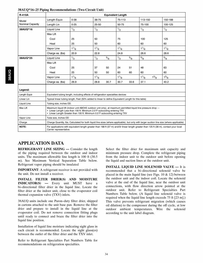
38AUQ*16--25 Piping Recommendations (Two-Circuit Unit)
R-410A Equivalent Length
ModelNominal Capacity
Length Equiv 0-38 38-75 75-113 113-150 150-188
Length Lin 0-25 25-50 50-75 75-100 100-125
38AUQ*16 Liquid Line 1/2 1/2 1/2 1/2 1/2
Max Lift
Cool 25 50 75 100 125
Heat 25 50 60 60 60
Vapor Line 11/8 11/8 11/8 11/8 11/8
Charge ea. (lbs) 20.9 22.8 24.8 26.6 28.6
38AUQ*25 Liquid Line 1/2 1/2 5/8 1/2 5/8 5/8 5/8
Max Lift
Cool 25 37 50 24 51 48 63
Heat 25 50 50 60 60 60 60
Vapor Line 11/8 11/8 11/8 11/8 13/8 13/8
Charge ea. (lbs) 26.9 28.8 30.7 30.7 33.6 37.1 40.2
Legend:
Length Equiv Equivalent tubing length, including effects of refrigeration specialties devices
Linear Lin Typical linear tubing length, Feet (50% added to linear to define Equivalent Length for this table)
Liquid Line Tubing size, inches OD.
Max Lift Maximum liquid lift (indoor unit ABOVE outdoor unit only), at maximum permitted liquid line pressure drop —S Linear Length Less than 100 ft: Minimum 2.0°F subcooling entering TXVS Linear Length Greater than 100 ft: Minimum 0.5°F subcooling entering TXV
Vapor Line Tube size, inches OD
Charge Charge Quantity, lbs. Calculated for both liquid line sizes (where applicable), but only with larger suction line size (where applicable)
NOTE: For applications with equivalent length greater than 188 ft (57 m) and/0r linear length greater than 125 ft (38 m), contact your localCarrier representative.
APPLICATION DATAREFRIGERANT LINE SIZING — Consider the lengthof the piping required between the outdoor and indoorunits. The maximum allowable line length is 100 ft (30.5m). See Maximum Vertical Separation Table below.Refrigerant vapor piping should be insulated
IMPORTANT: A refrigerant receiver is not provided withthe unit. Do not install a receiver.
INSTALL FILTER DRIER(S) AND MOISTUREINDICATOR(S) — Every unit MUST have abi--directional filter drier in the liquid line. Locate thefilter drier at the indoor unit, close to the evaporator coilthermal expansion valve (TXV) inlets.
38AUQ units include one Puron--duty filter drier, shippedin cartons attached to the unit base pan. Remove the filterdrier and prepare to install in the liquid line at theevaporator coil. Do not remove connection fitting plugsuntil ready to connect and braze the filter drier into theliquid line position.
Installation of liquid line moisture indicating sight glass ineach circuit is recommended. Locate the sight glass(es)between the outlet of the filter drier and the TXV inlet.
Refer to Refrigerant Specialties Part Numbers Table forrecommendations on refrigeration specialties.
Select the filter drier for maximum unit capacity andminimum pressure drop. Complete the refrigerant pipingfrom the indoor unit to the outdoor unit before openingthe liquid and suction lines at the outdoor unit.
INSTALL LIQUID LINE SOLENOID VALVE — It isrecommended that a bi--directional solenoid valve beplaced in the main liquid line (see Figs. 10 & 12) betweenthe outdoor unit and the indoor coil. Locate the solenoidvalve at the end of the liquid line, near the outdoor unitconnections, with flow direction arrow pointed at theoutdoor unit. Refer to Refrigerant Specialties PartNumbers Table below. (A liquid line solenoid valve isrequired when the liquid line length exceeds 75 ft [23 m].)This valve prevents refrigerant migration (which causesoil dilution) to the compressor during the off cycle, at lowoutdoor ambient temperatures. Wire the solenoidaccording to the unit label diagram.
38AUQ

35
15 DIAMSMIN 10
DIAMS8 DIAMS
MIN
INDOORCOIL CKT
AIRFLOW
TXVSENSINGBULB
EQUALIZER LINE
SIGHT GLASSA LOCATION
TXV
FILTER DRIERA LOCATION
LIQUIDLINESOLENOIDVALVE
FLOW
LEGENDTXV — Thermostatic Expansion Valve
C10133
Fig. 11 -- Location of Sight Glass(es) and Filter Driers(typical 38AUQ / 40RUQ size 07 & 08 system)
LEGENDTXV — Thermostatic Expansion Valve
INDOORCOIL CKT 2
AIRFLOW
INDOORCOIL CKT 1
AIRFLOW
15 DIAMSMIN 10
DIAMS8 DIAMS
MIN
TXVSENSINGBULB
EQUALIZER LINE
SIGHT GLASSLOCATION
TXVCKT 2
FILTER DRIERLOCATION
LIQUIDLINESOLENOIDVALVE
FLOWTXVSENSINGBULB
TXVCKT 1
8 DIAMSMIN
15 DIAMSMIN 10
DIAMS
A10134
Fig. 12 -- Location of Sight Glass(es) and Filter Driers(typical 38AUQ / 40RUQ size 12 system)
Refrigerant Specialties Part Numbers
LIQUID LINESIZE (in.)
LIQUID LINESOLENOID VALVE (LLSV)
SOLENOIDCOIL
SIGHTGLASS
3/8 EF680033 plus EF680039 biflow kit EF680037 KM6800081/2 EF680035 plus EF680039 biflow kit EF680037 KM6800045/8 EF680036 plus EF680039 biflow kit EF680037 KM680005
38AUQ

36
GUIDE SPECIFICATIONS -- 38AUQ07--25
Split System Heat Pump Outdoor Unit with PURON® Refrigerant
HVAC Guide Specifications — Section 15678
Size Range: 66,000 to 214,000 Btuh Heating6 to 20 Nominal Tons Cooling
Carrier Model Numbers: 38AUQ07 thru 25
Part 1 — General
1.01 SYSTEM DESCRIPTION
A. Outdoor--mounted, electrically controlled, air--cooled split system heat pump suitable for on--the--ground orrooftop installation. Unit shall consist of a scroll air--conditioning compressor assembly, an air--cooled coil, pro-peller--type condenser fans, and a control box. Unit shall discharge supply air upward as shown on contract draw-ings. Unit shall function as the outdoor component of an air to air electric heat pump system.
B. Unit must be designed with a Puron® (R--410A) refrigerant circuit to match Packaged Heat Pump Air HandlingUnit(s), 40RUQ for matched systems approved by the manufacturer.
1.02 QUALITY ASSURANCE
A. Unit shall be rated in accordance with AHRI Standard 340/360.B. Unit construction shall comply with ANSI/ASHRAE 15 safety code latest revision and comply with NEC.C. Unit shall be constructed in accordance with UL 1995 standard and shall carry the UL and UL, Canada label for
sizes 07--12 and ETL for 16 and 25 models.D. Unit cabinet shall be capable of withstanding 500--hour salt spray exposure per ASTM B117 (scribed specimen).E. Air--cooled outdoor coils shall be leak tested at 150 psig and pressure tested at 650 psig and qualified to UL burst
test at 1980 psig.F. Unit shall be manufactured in a facility registered to ISO 9001:2000 manufacturing quality standard.
1.03 DELIVERY, STORAGE AND HANDLINGUnit shall be shipped as single package only, and shall be stored and handled according to unit manufacturer’s recom-mendations.
1.04 WARRANTY (FOR INCLUSION BY SPECIFYING ENGINEER)
Part 2 — Products
2.01 EQUIPMENT
A. General:Factory--assembled, single piece, air--cooled split system heat pump. Contained within the unit enclosureshall be all factory wiring, piping, controls, compressor, holding charge Puron® (R--410A), and special featuresrequired prior to field start--up.
B. Unit Cabinet:6. Unit cabinet shall be constructed of galvanized steel, bonderized and coated with a pre--painted baked enamelfinish.
7. A heavy--gauge roll--formed perimeter base rail with forklift slots and lifting holes shall be provided to facilit-ate rigging.
C. Fans:1. Condenser fans shall be direct driven, propeller type, discharging air vertically upward.2. Fan blades shall be balanced.3. Condenser fan discharge openings shall be equipped with PVC coated steel wire safety guards.4. Condenser fan and motor shaft shall be corrosion resistant.
D. Compressor:1. Compressor shall be of the hermetic scroll type.2. Compressor shall be mounted on rubber grommets.3. Compressor shall include overload protection.4. Compressors shall be equipped with a crankcase heater.5. Compressor shall be equipped with internal high discharge temperature protection.
38AUQ

37
E. Coil:1. Coil shall be air--cooled and circuited for sub cooling during cooling mode of operation.2. Coil shall be constructed of aluminum fins (copper fins optional) mechanically bonded to internally groovedseamless copper tubes which are then cleaned, dehydrated, and sealed.
F. Refrigeration Components and Operation:1. Refrigeration circuit components shall include liquid line service valve, suction line service valve, a fullcharge of compressor oil, holding charge of refrigerant, and loose shipped refrigerant filter drier (one percircuit).
2. Precision--sized suction line accumulator on each refrigerant circuit shall protect from oil being removed fromthe scroll compressor rotating orbiter and plate during the activation of the defrost mode and switching backand forth from cooling and heating operations.
3. Unit shall be capable of starting and running up to 125_F (52_C) and down to 35_F (2_C) ambient outdoortemperature.
4. Unit shall operate at +/-- 10% from rated voltageG. Controls and Safeties:
1. Minimum control functions shall include:a. Control wire terminal blocks.b. Compressor lockout on auto--reset safety until reset from thermostat.c. Each unit shall utilize the Comfort Alert™ Diagnostic Board that provides:(1.) System Pressure Trip fault code indication(2.) Short Cycling fault code indication(3.) Locked Rotor fault code indication(4.) Open Circuit fault code indication(5.) Reverse Phase 3 fault code indication(6.) Welded Contactor fault code indication(7.) Low Voltage fault code indication(8.) Anti--short cycle protection(9.) Phase reversal protection
2. Minimum safety devices which are equipped with automatic reset (after resetting first at thermostat), shallinclude:a. High discharge pressure protection switch.b. Loss--of--charge protection switch.
H. Electrical Requirements:1. Unit electrical power shall be single--point connection.2. Unit control circuit shall contain a 75VA -- 24--v transformer for unit control.
I. Special Features:1. Unit--Mounted, Non--Fused Disconnect Switch: (Not available when unit MOCP electrical rating exceeds 80amps)Switch shall be factory--installed and internally mounted. NEC and UL--approved non--fused switch shallprovide unit power shutoff. Switch shall be accessible from outside the unit and shall provide power off lock-out capability.
2. Convenience Outlet:a. Powered convenience outlet.(1.) Outlet shall be powered from main line power to the rooftop unit.(2.) Outlet shall be powered from line side or load side of disconnect by installing contractor, as required
by code. If outlet is powered from load side of disconnect, unit electrical ratings shall be UL certi-fied and rated for additional outlet amperage.
(3.) Outlet shall be factory--installed and internally mounted with easily accessible 115--v female recept-acle.
(4.) Outlet shall include 15 amp GFI receptacles with independent fuse protection.(5.) Voltage required to operate convenience outlet shall be provided by a factory--installed step--down
transformer.(6.) Outlet shall be accessible from outside the unit.(7.) Outlet shall include a field--installed “Wet in Use” cover.
38AUQ

38
b. Non--Powered convenience outlet.(1.) Outlet shall be powered from a separate 115/120v power source.(2.) A transformer shall not be included.(3.) Outlet shall be factory--installed and internally mounted with easily accessible 115--v female recept-
acle.(4.) Outlet shall include 15 amp GFI receptacles with independent fuse protection.(5.) Outlet shall be accessible from outside the unit.(6.) Outlet shall include a field--installed “Wet in Use” cover.
3. Low--Ambient Temperature Control:A low--ambient temperature control shall be available as a factory--installed option or as a field--installed ac-cessory. This low--ambient control shall regulate speed of the condenser--fan motors in response to the satur-ated condensing temperature of the unit. The control shall maintain correct condensing pressure at outdoortemperatures down to –20_F (--29_C).
4. Optional Outdoor Coil Materials:a. Pre--Coated Aluminum--Fin Coils:
Coils shall have a durable epoxy--phenolic coating to provide protection in mildly corrosive coastal envir-onments. Coating shall be applied to the aluminum fin stock prior to the fin stamping process to create aninert barrier between the aluminum fin and copper tube. Epoxy--phenolic barrier shall minimize galvanicaction between dissimilar metals.
b. E--Coated Aluminum--Fin Coils:Coils shall have a flexible epoxy polymer coating uniformly applied to all coil surface areas without ma-terial bridging between fins. Coating process shall ensure complete coil encapsulation. Color shall be highgloss black with gloss requirements of 60_ of 65 to 90% per ASTM D523--89. Uniform dry film thicknessfrom 0.8 to 1.2 mil on all surface areas including fin edges. Superior hardness characteristics of 2H perASTM D3363--92A and cross hatch adhesion of 4B--5B per ASTM D3359--93. Impact resistance shall beup to 160 in./lb (ASTM D2794--93). Humidity and water immersion resistance shall be up to a minimumof 1000 and 250 hours respectively (ASTM D2247--92 and ASTM D870--92). Corrosion durability shall beconfirmed through testing to no less than 1000 hours salt spray per ASTM B117--90. Coil constructionshall be aluminum fins mechanically bonded to copper tubes.
5. Thermostat Controls:a. Programmable multi--stage thermostat with 7--day clock, holiday scheduling, large backlit display, remote
sensor capability, and Title 24 compliance.b. Commercial electronic thermostat with 7--day time clock, auto--changeover, multistage capability, and
large LCD temperature display.c. Carrier PremierLink™ Controller – Field Installed:
This control will function with CCN and ComfortVIEW™ software. It shall also be compatible with Com-fortLink controllers. It shall be ASHRAE 62--99 compliant. It shall accept a CO2 sensor in the conditionedspace and be Demand Control Ventilation (DCV) ready. The communication rate must be 38.4K or faster.
6. Louvered hail Guard Package:Louvered hail guard package shall protect coils against damage from hail and other flying debris.
7. Outdoor Coil Grille:Grille shall add decorative appearance to unit and protect outdoor coil from large objects and vandalism.
Copyright 2010 Carrier Corp. S 7310 W. Morris St. S Indianapolis, IN 46231 Printed in U.S.A. Edition Date: 12/10
Manufacturer reserves the right to change, at any time, specifications and designs without notice and without obligations.
Catalog No: 38AUQ---03PD
Replaces: 38AUQ---02PD
38AUQ