product data - eissa | aire acondicionado · ning in series allows carrier's 19xrd chillers to...
TRANSCRIPT
Copyright 2011 Carrier Corporation Form 19XRD-3PD
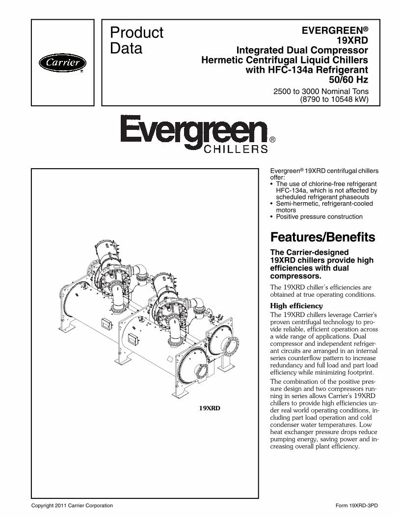
Evergreen® 19XRD centrifugal chillers offer:• The use of chlorine-free refrigerant
HFC-134a, which is not affected by scheduled refrigerant phaseouts
• Semi-hermetic, refrigerant-cooled motors
• Positive pressure construction
Features/BenefitsThe Carrier-designed19XRD chillers provide high efficiencies with dual compressors. The 19XRD chiller’s efficiencies are obtained at true operating conditions.
High efficiencyThe 19XRD chillers leverage Carrier's proven centrifugal technology to pro-vide reliable, efficient operation across a wide range of applications. Dual compressor and independent refriger-ant circuits are arranged in an internal series counterflow pattern to increase redundancy and full load and part load efficiency while minimizing footprint. The combination of the positive pres-sure design and two compressors run-ning in series allows Carrier's 19XRD chillers to provide high efficiencies un-der real world operating conditions, in-cluding part load operation and cold condenser water temperatures. Low heat exchanger pressure drops reduce pumping energy, saving power and in-creasing overall plant efficiency.
EVERGREEN®
19XRDIntegrated Dual Compressor
Hermetic Centrifugal Liquid Chillerswith HFC-134a Refrigerant
50/60 Hz2500 to 3000 Nominal Tons
(8790 to 10548 kW)
ProductData
19XRD
a19-1971
®
evergrn

2
Low starting currentThe two compressors start up sequen-tially and therefore reduce the inrush current. Compared to a single com-pressor chiller, the 19XRD dual com-pressors reduce 40% of the inrush current.
Environmental leadershipCarrier has long been committed to the environment and its sustainability. The 19XRD chillers provide our customers with a high-efficiency, chlorine-free long-term solution unaffected by refrig-erant phaseouts. Carrier’s decision to utilize non-ozone depleting HFC-134a refrigerant provides our customers with a safe and environmentally sound choice without compromising efficiency.
ReliabilityThe 19XRD chiller’s simple, single-stage positive-pressure compressor, coupled with ASME (American Society of Mechanical Engineers) constructed heat exchangers, ensures reliability and sustainability. Hermetic motors oper-ate in a clean-liquid, refrigerant-cooled environment. The hermetic design eliminates the problem of shaft seal leaks and refrigerant/oil loss.
Positive pressure designThe 19XRD chiller’s positive pressure design reduces the chiller size com-pared to low-pressure designs. The smaller size minimizes the need for valuable mechanical room floor space. In addition, positive pressure designs eliminate the need for costly low-pres-sure containment devices, reducing the initial cost of the system.
Optional refrigerant isolation valvesThis system allows the refrigerant to be stored inside the chiller during servicing, reducing refrigerant loss and eliminating time-consuming transfer procedures. The self-contained 19XRD chiller does not require additional remote storage systems.
Hermetic compressor featuresSingle-stage design increases prod-uct reliability by eliminating the addi-tional moving parts associated with multiple stage chillers, such as addi-tional guide vanes and complexeconomizers.
Aerodynamically contoured im-pellers use high back sweep main blades with low-profile intermediate splitter blades. The impellers are aero-dynamically contoured to improve compressor full load and part load operating efficiency.Hermetic motors are hermetically sealed from the machine room. Cool-ing is accomplished by spraying liquid refrigerant on the motor windings. This highly efficient motor cooling method results in the use of smaller, cooler-running motors than could be realized with air-cooled designs of the same type.
In addition, the hermetic motor de-sign eliminates:• Compressor shaft seals that require
maintenance and increase the likeli-hood of refrigerant leaks
• Shaft alignment problems that occur with open-drive designs during start-up and operation, when equip-ment temperature variations cause thermal expansion
• High noise levels that are common with air-cooled motors, which radi-ate noise to the machine room and adjacent areas
• Machine room cooling requirements associated with air-cooled motors, which dissipate heat to the machine room
Compressors are 100% run-test-ed to ensure proper operation of all compressor systems, including oil man-agement, vibration, electrical, power transmission, and compression.
Heat exchanger featuresThe 19XRD chiller utilizes ASME (American Society of Mechanical Engi-neers) standards for pressure vessels. This feature requires the use of an in-dependent agency to certify the de-sign, manufacture, and testing of all heat exchangers, ensuring the ulti-mate in heat exchanger safety, reliabili-ty, and long life.Double-grooved tube sheet holes eliminate the possibility of leaks be-tween the water and refrigerant sys-tem, increasing product reliability.Condenser baffle prevents direct im-pingement of high velocity compressor gas onto the condenser tubes. The baf-fle eliminates the related vibration and wear of the tubes and distributes the refrigerant flow evenly over the length of the vessel for improved efficiency.Refrigerant filter drier isolation valves allow filter drier replacement without the expense of removing or transferring the refrigerant.Thermowells and pressure trans-ducers for evaporator and condenser temperature and pressure indication can be changed without removing or transferring the refrigerant charge, providing easier calibration and a re-duction in service time and expense.FLASC (flash subcooler), located in the bottom of the condenser, increases the refrigeration effect by cooling the condensed liquid refrigerant to a lower temperature. This results in reduced compressor power consumption.
Features/Benefits (cont)
Table of contentsPage
Features/Benefits . . . . . . . . . . . . . . . . . . . . . . . . . . . . . . . . . . . . . . . . . 1-4Model Number Nomenclature . . . . . . . . . . . . . . . . . . . . . . . . . . . . . . . . . . 5Chiller Components . . . . . . . . . . . . . . . . . . . . . . . . . . . . . . . . . . . . . . . . 6,7Physical Data . . . . . . . . . . . . . . . . . . . . . . . . . . . . . . . . . . . . . . . . . . . . 8,9Options and Accessories . . . . . . . . . . . . . . . . . . . . . . . . . . . . . . . . . . . . . . 9Dimensions . . . . . . . . . . . . . . . . . . . . . . . . . . . . . . . . . . . . . . . . . . . . 10,11Selection Procedure . . . . . . . . . . . . . . . . . . . . . . . . . . . . . . . . . . . . . . . . 12Performance Data . . . . . . . . . . . . . . . . . . . . . . . . . . . . . . . . . . . . . . . . . . 12Electrical Data . . . . . . . . . . . . . . . . . . . . . . . . . . . . . . . . . . . . . . . . . . . . . 12Controls . . . . . . . . . . . . . . . . . . . . . . . . . . . . . . . . . . . . . . . . . . . . . . 13-15Typical Piping and Wiring . . . . . . . . . . . . . . . . . . . . . . . . . . . . . . . . . . . . . 16Application Data . . . . . . . . . . . . . . . . . . . . . . . . . . . . . . . . . . . . . . . . 17-23Guide Specifications . . . . . . . . . . . . . . . . . . . . . . . . . . . . . . . . . . . . . 24-28
3
AccuMeter™ system regulates refrig-erant flow according to load condi-tions, providing a liquid seal at all oper-ating conditions and eliminating unin-tentional hot gas bypass.
Integrated control featuresThe 19XRD integrated controller is an easy-to-use interface. Each controller integrates the operating data of both circuits, which makes chiller control and maintenance easier. For identical compressor configuration, each circuit can be designated as the lead circuit to balance the operating time of the com-pressors. Due to the lead/lag opera-tion, chiller and system efficiency is im-proved. One circuit can run while the other is stopped for maintenance so operation will not be interrupted. The two redundant systems offer higherreliability for the chiller and system.Direct Digital Product Integrated Control (PIC II) provides unmatched flexibility and functionality. Each unit integrates directly with the Carrier Comfort Network® (CCN) system,providing a system solution to controlsapplications.International Chiller Visual Con-trol (ICVC) can be configured to dis-play units in English or metric and pro-vides unparalleled ease of operation.
The default display offers all in one glance review of key chiller operation data, simplifying the interactionbetween chiller and user.
Features include:• Display of over 125 operating, sta-
tus, and diagnostic messages for improved user interface
• Monitoring of over 100 functions and conditions to protect the chiller from abnormal conditions
• Modular pull-out/plug-in design, reducing wiring requirements and providing easy installation
• Low-voltage (24 v) design, providing the ultimate assurance of personal safety and control integrityThe display modes include 3 standard
languages: English, Chinese, and Korean.Automatic capacity override func-tion unloads the compressor whenev-er key safety limits are approached, in-creasing unit life.Chilled water reset can be accom-plished manually or automatically from the building management system. The reset saves energy when warmer chilled water can be used.Demand limiting feature limits the power draw of the chiller during peak loading conditions. When incorporated into the Carrier Comfort Network building automation system, a red line command holds chillers at their present capacity and prevents any other chill-ers from starting. If a load shed signal is received, the compressors are unloaded to avoid high demand charges whenever possible.
Ramp loading ensures a smooth pulldown of water loop temperature and prevents a rapid increase in com-pressor power consumption during the pulldown period.Automated controls test can be ex-ecuted prior to start-up to verify that the entire control system is functioning properly.365-day real time clock feature al-lows the operator to program a yearly schedule for each week, weekends, and holidays.Occupancy schedules can be pro-grammed into the controller to ensure that the chiller only operates when cooling is required.Extensive service menu features in-clude password protection to prevent unauthorized access to the service menu. Built-in diagnostic capabilities assist in troubleshooting and recom-mend proper corrective action for pre-set alarms, resulting in greateroperating time.Alarm file maintains the last 25 time and date-stamped alarm and alert mes-sages in memory. This function reduc-es troubleshooting time and cost.Configuration data backup in non-volatile memory provides protection during power failures and eliminates time consuming control reconfiguration.
4
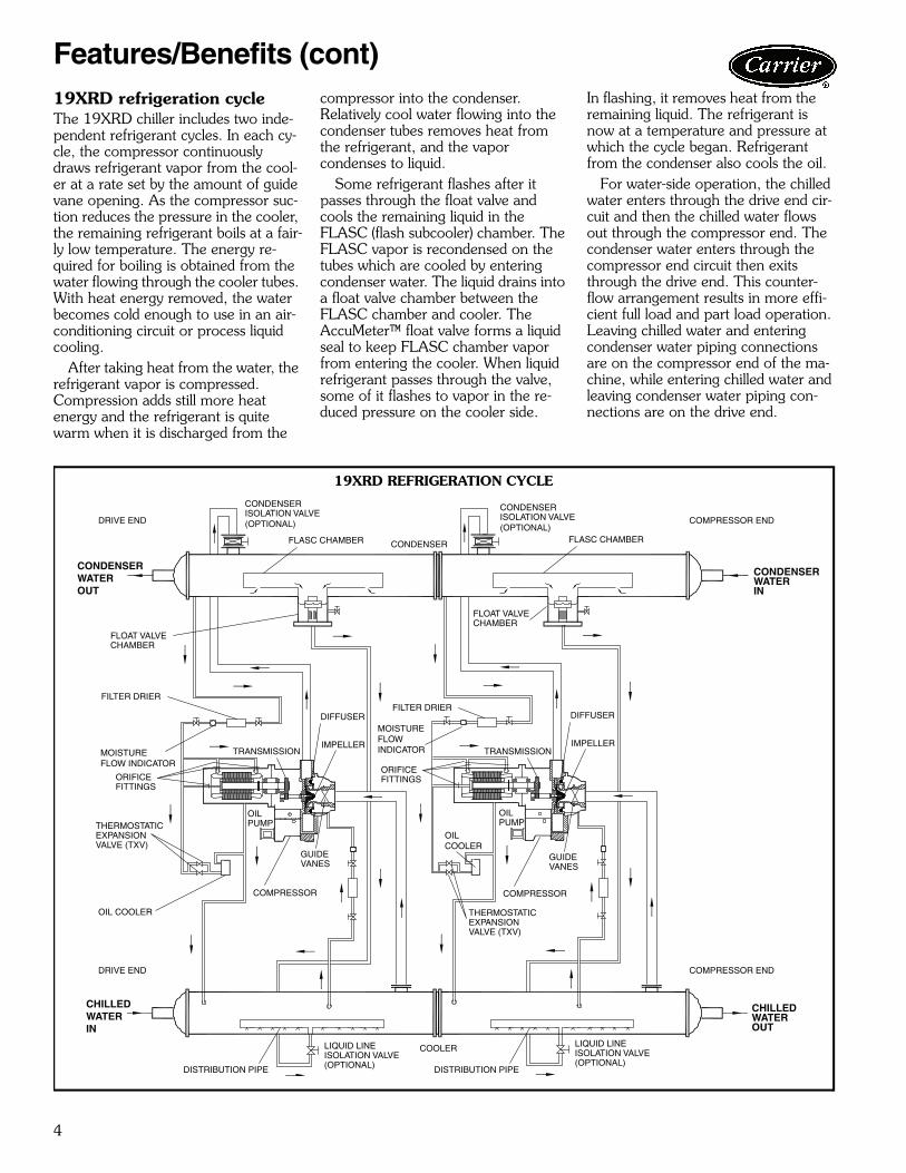
19XRD refrigeration cycleThe 19XRD chiller includes two inde-pendent refrigerant cycles. In each cy-cle, the compressor continuously draws refrigerant vapor from the cool-er at a rate set by the amount of guide vane opening. As the compressor suc-tion reduces the pressure in the cooler, the remaining refrigerant boils at a fair-ly low temperature. The energy re-quired for boiling is obtained from the water flowing through the cooler tubes. With heat energy removed, the water becomes cold enough to use in an air-conditioning circuit or process liquid cooling.
After taking heat from the water, the refrigerant vapor is compressed. Compression adds still more heat energy and the refrigerant is quite warm when it is discharged from the
compressor into the condenser. Relatively cool water flowing into the condenser tubes removes heat from the refrigerant, and the vapor condenses to liquid.
Some refrigerant flashes after it passes through the float valve and cools the remaining liquid in the FLASC (flash subcooler) chamber. The FLASC vapor is recondensed on the tubes which are cooled by entering condenser water. The liquid drains into a float valve chamber between the FLASC chamber and cooler. The AccuMeter™ float valve forms a liquid seal to keep FLASC chamber vapor from entering the cooler. When liquid refrigerant passes through the valve, some of it flashes to vapor in the re-duced pressure on the cooler side.
In flashing, it removes heat from the remaining liquid. The refrigerant is now at a temperature and pressure at which the cycle began. Refrigerant from the condenser also cools the oil. For water-side operation, the chilled water enters through the drive end cir-cuit and then the chilled water flows out through the compressor end. The condenser water enters through the compressor end circuit then exits through the drive end. This counter-flow arrangement results in more effi-cient full load and part load operation. Leaving chilled water and entering condenser water piping connections are on the compressor end of the ma-chine, while entering chilled water and leaving condenser water piping con-nections are on the drive end.
FLASC CHAMBER CONDENSER
CONDENSERWATERIN
CONDENSERWATEROUT
FLOAT VALVECHAMBER
FILTER DRIER
MOISTUREFLOW INDICATOR
THERMOSTATICEXPANSIONVALVE (TXV)
OIL COOLER
CHILLEDWATERIN
CHILLEDWATEROUT
COOLER
DISTRIBUTION PIPE
COMPRESSOR
DIFFUSER
IMPELLER
CONDENSERISOLATION VALVE(OPTIONAL)
GUIDEVANES
OILPUMP
TRANSMISSION
LIQUID LINEISOLATION VALVE(OPTIONAL)
ORIFICEFITTINGS
COMPRESSOR
GUIDEVANES
OILCOOLER
THERMOSTATICEXPANSIONVALVE (TXV)
DIFFUSER
IMPELLERTRANSMISSION
FILTER DRIER
MOISTUREFLOWINDICATOR
CONDENSERISOLATION VALVE(OPTIONAL)
FLASC CHAMBER
FLOAT VALVECHAMBER
OILPUMP
ORIFICEFITTINGS
LIQUID LINEISOLATION VALVE(OPTIONAL)
DISTRIBUTION PIPE
DRIVE END
DRIVE END COMPRESSOR END
COMPRESSOR END
19XRD REFRIGERATION CYCLE
a19-1987
Features/Benefits (cont)
5
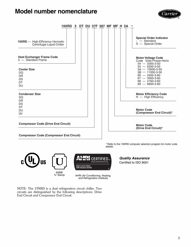
19XRD — High-Efficiency HermeticCentrifugal Liquid Chiller
19XRD 5 DT DU 57F 587 MF MF H 5A
Motor Voltage CodeCode Volts-Phase-Hertz 54 — 3300-3-50 55 — 6300-3-50 5A 5B 66 — 2400-3-60 67 — 3300-3-60 68 — 4160-3-60 69 — 6900-3-60
——
10000-3-5011000-3-50
Special Order Indicator- — StandardS — Special Order
Motor Efficiency CodeH — High Efficiency
Motor Code(Compressor End Circuit)*
Motor Code(Drive End Circuit)*
Compressor Code (Compressor End Circuit)
Compressor Code (Drive End Circuit)
Heat Exchanger Frame Code5 — Standard Frame
Cooler SizeDQDRDSDTDU
Condenser SizeDQDRDSDTDUDV
* Refer to the 19XRD computer selection program for motor codedetails.
NOTE: The 19XRD is a dual refrigeration circuit chiller. Twocircuits are distinguished by the following descriptions: DriveEnd Circuit and Compressor End Circuit.
a19-1970
Quality AssuranceCertified to ISO 9001
AHRI (Air Conditioning, Heating, and Refrigeration Institute)
ASME‘U’ Stamp
Model number nomenclature

6
Chiller components
1 2 3 4 5 6
789101112131415
COMPRESSOR COMPONENTS
LEGEND1 — Motor Stator 9 — Impeller2 — Motor Rotor 10 — Pipe Diffuser3 — Motor Shaft Journal Bearings 11 — High Speed Pinion Gear4 — Low Speed Bull Gear 12 — Oil Heater5 — High Speed Shaft Thrust Bearing 13 — High Speed Shaft Bearing6 — High Speed Shaft Bearing 14 — Oil Pump Motor7 — Variable Inlet Guide Vanes 15 — Oil Filter8 — Impeller Shroud
a19-
7
1 23
4
56
12
34
5
6
7
8
910
1112
1179
10
1213
14
13
15
OUT
IN
OUT
IN
16
17
18
19
2018
1719
20
21
2223
2425
2223
242526
21
27
2829
3031
2829
3031
OUT
IN
OUT
FRONT VIEW
REAR VIEW
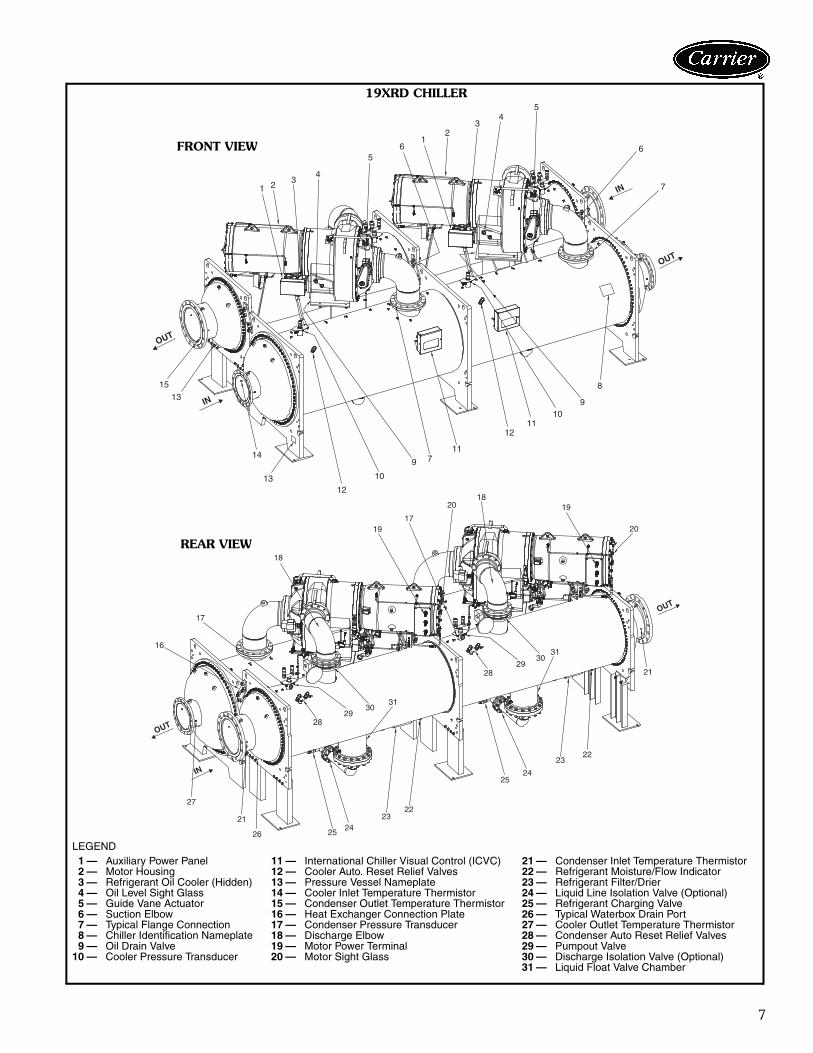
LEGEND1 — Auxiliary Power Panel 11 — International Chiller Visual Control (ICVC) 21 — Condenser Inlet Temperature Thermistor2 — Motor Housing 12 — Cooler Auto. Reset Relief Valves 22 — Refrigerant Moisture/Flow Indicator3 — Refrigerant Oil Cooler (Hidden) 13 — Pressure Vessel Nameplate 23 — Refrigerant Filter/Drier4 — Oil Level Sight Glass 14 — Cooler Inlet Temperature Thermistor 24 — Liquid Line Isolation Valve (Optional)5 — Guide Vane Actuator 15 — Condenser Outlet Temperature Thermistor 25 — Refrigerant Charging Valve6 — Suction Elbow 16 — Heat Exchanger Connection Plate 26 — Typical Waterbox Drain Port7 — Typical Flange Connection 17 — Condenser Pressure Transducer 27 — Cooler Outlet Temperature Thermistor8 — Chiller Identification Nameplate 18 — Discharge Elbow 28 — Condenser Auto Reset Relief Valves9 — Oil Drain Valve 19 — Motor Power Terminal 29 — Pumpout Valve
10 — Cooler Pressure Transducer 20 — Motor Sight Glass 30 — Discharge Isolation Valve (Optional)31 — Liquid Float Valve Chamber
19XRD CHILLER
a19-1972
a19-1973

8
19XRD COMPRESSOR AND MOTOR WEIGHTS FOR EACH CIRCUIT*(High Efficiency, Frame Size 5†, Medium and High Voltage)
* Total compressor weight is the sum of the compressor aerodynamiccomponents (compressor weight column), stator, rotor, and end bellcover weights.† Compressor size number is the first digit of the compressor code. SeeModel Number Nomenclature on page 5.**Compressor aerodynamic components weight only. Does not includemotor weight.
19XRD ADDITIONAL COOLER COMPONENT WEIGHTS 19XRD ADDITIONAL CONDENSER COMPONENT WEIGHTS
19XRD HEAT EXCHANGER WEIGHTS FOR EACH MODULE (Standard NIH 150 psig Waterboxes)
*Rigging weights are for standard tubes of standard wall thickness (SUPERE2 and SPIKE FIN 3, 0.025-in. [0.635 mm]).NOTES:
1. Weight for the heat exchangers is per module. Weight is based on0.025 in. (0.635 mm) wall standard tubing. Refer to E-Cat for spe-cial tubes.
2. All weights for standard 1-pass NIH (nozzle-in-head) design.3. Consult factory for higher pressure design.
MOTOR CODE VOLTAGE CODEENGLISH (lb) SI (kg)
CompressorWeight**
MotorWeight
End BellCover Weight
CompressorWeight**
MotorWeight
End BellCover Weight
EL 54, 55, 66, 67, 68, 69 7285 4171 414 3307 1892 188
EM 54, 55, 66, 67, 68, 69 7285 4171 414 3307 1892 188
EN 54, 55, 66, 67, 68, 69 7285 4371 414 3307 1983 188
EP 54, 55, 66, 67, 68, 69 7285 4371 414 3307 1983 188
MD5A 7285 4548 414 3307 2063 188
5B 7285 4645 414 3307 2107 188
MF5A 7285 4726 414 3307 2144 188
5B 7285 4890 414 3307 2218 188
COMPONENTFRAME 5
COMPRESSOR
lb kg
Suction Elbow 407 185
Control Panel 34 15
Optional Cooler Inlet Isolation Valve 24 11
COMPONENTFRAME 5
COMPRESSOR
lb kg
Discharge Elbow 325 147
Optional Discharge Isolation Valve 108 49
CODE(FRAMECODE 5)
ENGLISH (lb) SI (kg)Dry Rigging
Weight* Machine Charge Dry Rigging Weight* Machine Charge
CoolerOnly
CondenserOnly Refrigerant Weight Water Weight Cooler
OnlyCondenser
OnlyRefrigerant Weight Water Weight
Cooler Condenser Cooler Condenser Cooler Condenser Cooler CondenserDQ 29862 24371 3224 1772 5424 4979 13545 11054 1462 804 2460 2258DR 30526 24898 3296 1738 5710 5220 13846 11294 1495 788 2590 2368DS 31273 25416 3534 1706 5999 5461 14185 11529 1603 774 2721 2477DT 31950 25936 3768 1672 6292 5702 14492 11764 1709 758 2854 2586DU 32635 26456 4004 1640 6587 5943 14803 12000 1816 744 2988 2696DV — 26923 — 1606 - 6187 — 12212 — 728 — 2806
Physical data

9
19XRD ADDITIONAL HEAT EXCHANGER WEIGHTS FOR MARINE WATERBOXES*
150 PSIG (1034 kPa) MARINE WATERBOXES
*Add to cooler and condenser weights for total heat exchanger weights.Cooler and condenser weights may be found in the 19XRD ModularUnits Heat Exchanger Weights for Each Module table on page 8.NOTES:
1. Weight for the heat exchangers is per module. 2. Consult factory for higher pressure design.
19XRD WATERBOX COVER WEIGHTS
NOTES:1. Weight for a NIH (nozzle-in-head) 1-pass 150 psig cover is already
included in the heat exchanger weights shown on page 8. 2. Consult factory for higher pressure design.
Options and accessories
*Factory installed.†Field installed.**Standard waterboxes are nozzle-in-head type, 150 psig (1034 kPa).††Sponsored by ASHRAE (American Society of Heating, Refrigerating,and Air Conditioning Engineers).***Registered trademark of Echelon Corporation.
CODE(FRAMECODE 5)
ENGLISH (lb) SI (kg)
Cooler Condenser Cooler Condenser
DQ 2568 2141 1166 972DR 2568 2141 1166 972DS 2568 2141 1166 972DT 2568 2141 1166 972DU 2568 2141 1166 972DV 2568 2141 1166 972
WATERBOXTYPE
ENGLISH (lb) SI (kg)Cooler Condenser Cooler Condenser
NIH, 150 psig 1115 855 506 388Marine, 150 psig 3683 2996 1672 1360
ITEM OPTION* ACCESSORY†Thermal Insulation (Except Waterbox Covers) XMarine Waterboxes, 150 psig (1034 kPa)** XFlanged Cooler and/or Condenser Waterbox Nozzles X0.028 or 0.035 in. (0.711 or 0.889 mm) Internally/Externally Enhanced Copper Tubing — Cooler X0.028 or 0.035 in. (0.711 or 0.889 mm) Internally/Externally Enhanced Copper Tubing — Condenser XVictaulic Connection XRefrigerant Isolation Valves XFree-Standing Solid-State Starter XFree-Standing Across the Line Starter XBACnet†† Communications XLonWorks*** Carrier Translator XStand-Alone Pumpout Unit XSeparate Storage Tank and Pumpout Unit XExport Crating X

10
AB
C
COMPRESSOR END
DRIVE END
19XRD DIMENSIONS — NOZZLE-IN-HEAD WATERBOXES
NOTES:1. Service access should be provided per American Society of Heating,
Refrigerating, and Air Conditioning Engineers (ASHRAE) 15, latest edition, National Fire Protection Association (NFPA) 70, and local safety code.
2. ‘A’ length dimensions shown are for standard 150 psig design and flangeconnections.
HEAT EXCHANGERSIZE (FRAME 5) WATERBOX TYPE WATER
PRESSURE
DIMENSIONSA (length) B (width) C (height)
ft-in. mm ft-in. mm ft-in. mm
DQ, DR, DS, DT, DU, DV Nozzle-In-Head 150 psig(1034 kPa) 21-10 6654 10-8 3/8 3261 11-0 9/16 3367
a19-1974
Dimensions
11
AB
C
COMPRESSOR END
DRIVE END
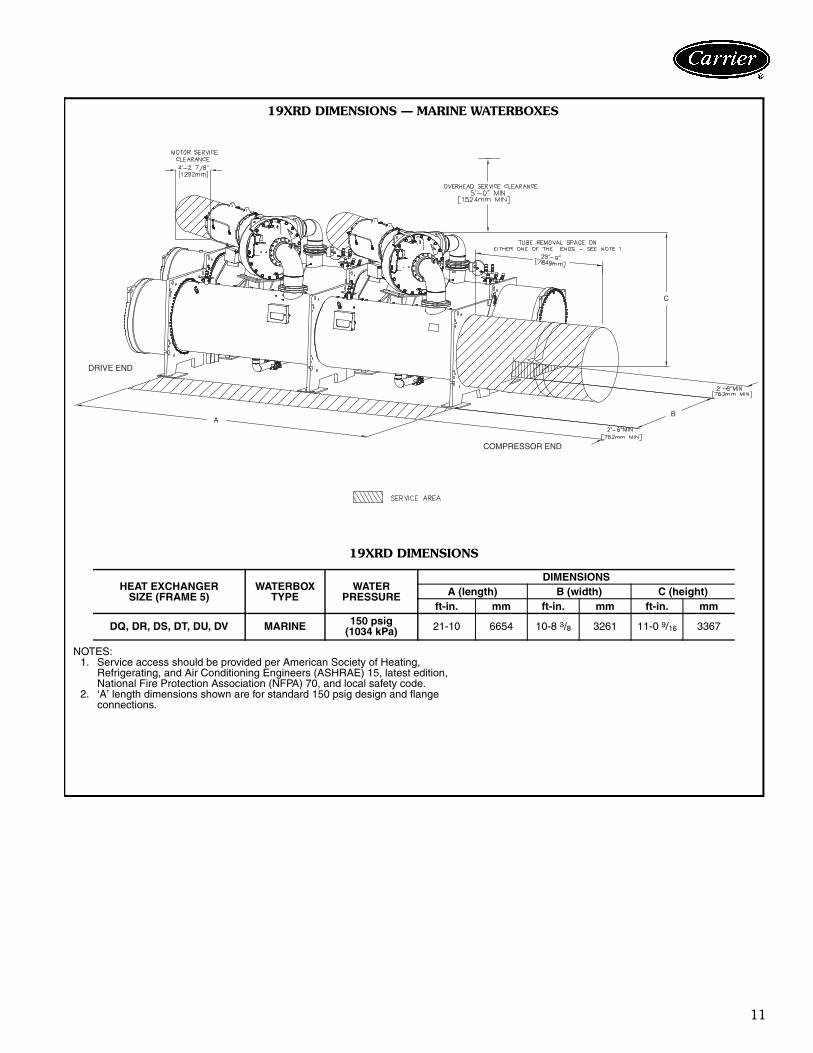
19XRD DIMENSIONS — MARINE WATERBOXES
19XRD DIMENSIONS
NOTES:1. Service access should be provided per American Society of Heating,
Refrigerating, and Air Conditioning Engineers (ASHRAE) 15, latest edition,National Fire Protection Association (NFPA) 70, and local safety code.
2. ‘A’ length dimensions shown are for standard 150 psig design and flangeconnections.
HEAT EXCHANGERSIZE (FRAME 5)
WATERBOX TYPE
WATERPRESSURE
DIMENSIONSA (length) B (width) C (height)
ft-in. mm ft-in. mm ft-in. mm
DQ, DR, DS, DT, DU, DV MARINE 150 psig(1034 kPa) 21-10 6654 10-8 3/8 3261 11-0 9/16 3367
a19-1975
12
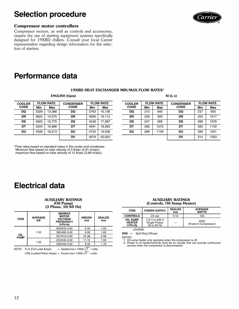
Compressor motor controllersCompressor motors, as well as controls and accessories,require the use of starting equipment systems specificallydesigned for 19XRD chillers. Consult your local Carrierrepresentative regarding design information for the selec-tion of starters.
Performance data
19XRD HEAT EXCHANGER MIN/MAX FLOW RATES*
ENGLISH (Gpm) SI (L/s)
*Flow rates based on standard tubes in the cooler and condenser.Minimum flow based on tube velocity of 3 ft/sec (0.91 m/sec); maximum flow based on tube velocity of 12 ft/sec (3.66 m/sec).
Electrical data
AUXILIARY RATINGS (Oil Pump)
(3 Phase, 50/60 Hz)
NOTE: FLA (Full Load Amps) = Sealed kva • 1000/ • volts
LRA (Locked Rotor Amps) = Inrush kva • 1000/ • volts
AUXILIARY RATINGS (Controls, Oil Sump Heater)
LEGEND
NOTES:1. Oil sump heater only operates when the compressor is off.2. Power to oil heater/controls must be on circuits that can provide continuous
service when the compressor is disconnected.
COOLERCODE
FLOW RATE CONDENSERCODE
FLOW RATEMin Max Min Max
DQ 3329 13,388 DQ 3763 15,136
DR 3624 14,575 DR 4006 16,112
DS 3922 15,775 DS 4248 17,087
DT 4224 16,988 DT 4491 18,063
DU 4528 18,213 DU 4733 19,038
DV 4979 20,025
COOLERCODE
FLOW RATE CONDENSERCODE
FLOW RATEMin Max Min Max
DQ 210 845 DQ 237 955
DR 229 920 DR 253 1017
DS 247 995 DS 268 1078
DT 266 1072 DT 283 1140
DU 286 1149 DU 299 1201
DV 314 1263
ITEM AVERAGEkW
MIN/MAXMOTOR
VOLTAGE/FREQUENCY
V-Ph-Hz
INRUSHkva
SEALEDkva
OILPUMP
1.35200/240-3-60 9.34 1.65380/480-3-60 9.09 1.60507/619-3-60 24.38 2.08
1.50220/240-3-50 11.15 1.93346/440-3-50 8.30 1.76
3—
3—
ITEM POWER SUPPLY SEALEDkva
AVERAGEWATTS
CONTROLS 24-vac 0.12 120OIL SUMPHEATERV-Ph-Hz
115 V or 230 V,Single Phase,50 or 60 Hz
— 2200(Frame 5 Compressor)
SRD — Split Ring Diffuser
Selection procedure
13
Integrated controlsThe 19XRD controls maintain both compressor circuit op-erations at the best efficiency while maintaining the definedload. This is accomplished by designating one circuit as thelead and the other as the lag. The lead circuit has the pri-mary responsibility of controlling capacity to meet the de-mand requirements. When the demand exceeds a config-ured limit, the lag compressor will start. The lag circuit isconfigured so that it will match the percent capacity of thelead. When the load reduces below a defined deadband,the lag circuit will be directed to stop, and the lead will in-crease capacity to meet the demand. To enable operation of one circuit during maintenance ofthe other circuit, compressors have to be selected so thateither circuit can operate when the other circuit is com-pletely shut down. The system design includes controlfunctions, safeties, and starters provided independently ineach circuit. This is accomplished with the 19XRD soft-ware design, which maintains a synchronized overall chilleroperational status at either control panel, regardless of itslead or lag position.
Control systemThe microprocessor control on each Carrier centrifugalchiller is factory mounted, wired, and tested to ensure ma-chine protection and efficient capacity control. In addition,the program logic ensures proper starting, stopping, andrecycling of the chiller and provides a communication linkto the Carrier Comfort Network® (CCN) system.
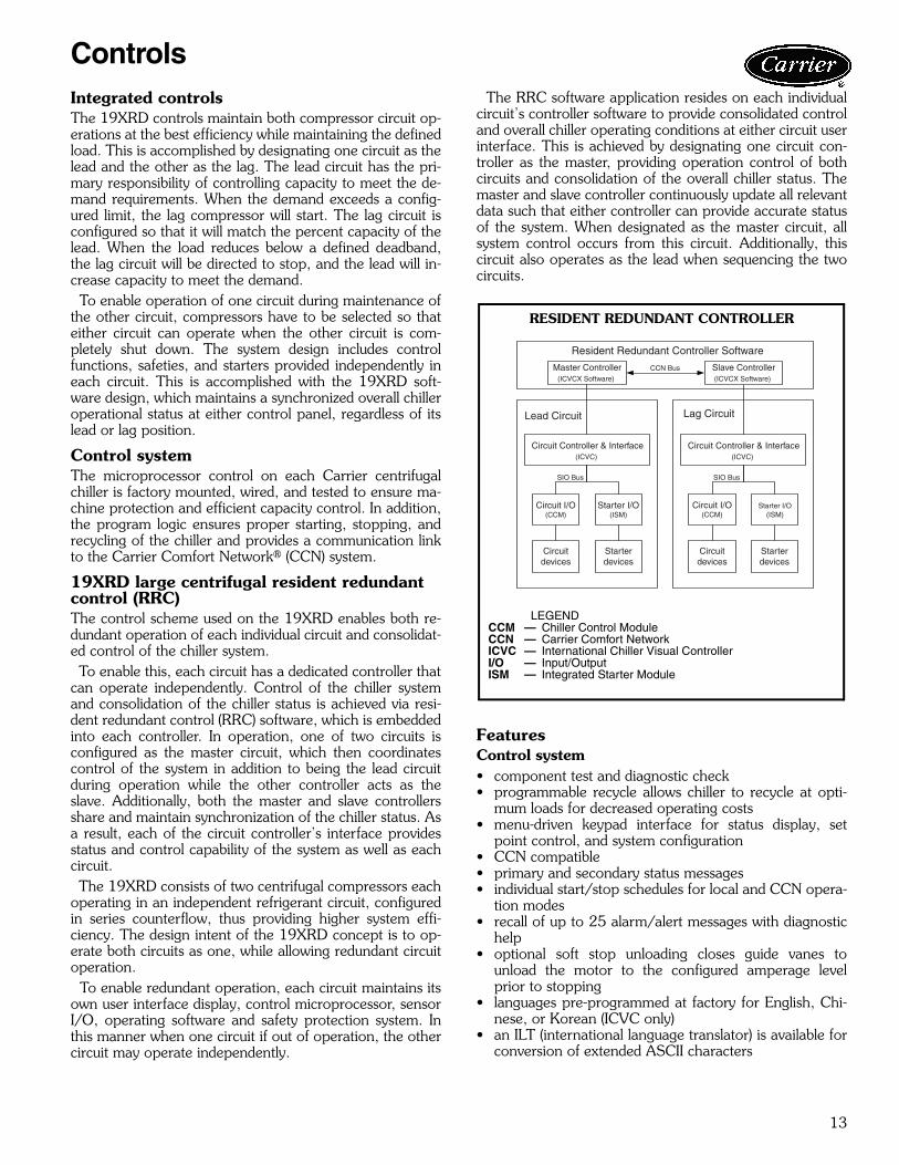
19XRD large centrifugal resident redundant control (RRC)The control scheme used on the 19XRD enables both re-dundant operation of each individual circuit and consolidat-ed control of the chiller system. To enable this, each circuit has a dedicated controller thatcan operate independently. Control of the chiller systemand consolidation of the chiller status is achieved via resi-dent redundant control (RRC) software, which is embeddedinto each controller. In operation, one of two circuits isconfigured as the master circuit, which then coordinatescontrol of the system in addition to being the lead circuitduring operation while the other controller acts as theslave. Additionally, both the master and slave controllersshare and maintain synchronization of the chiller status. Asa result, each of the circuit controller’s interface providesstatus and control capability of the system as well as eachcircuit. The 19XRD consists of two centrifugal compressors eachoperating in an independent refrigerant circuit, configuredin series counterflow, thus providing higher system effi-ciency. The design intent of the 19XRD concept is to op-erate both circuits as one, while allowing redundant circuitoperation. To enable redundant operation, each circuit maintains itsown user interface display, control microprocessor, sensorI/O, operating software and safety protection system. Inthis manner when one circuit if out of operation, the othercircuit may operate independently.
The RRC software application resides on each individualcircuit’s controller software to provide consolidated controland overall chiller operating conditions at either circuit userinterface. This is achieved by designating one circuit con-troller as the master, providing operation control of bothcircuits and consolidation of the overall chiller status. Themaster and slave controller continuously update all relevantdata such that either controller can provide accurate statusof the system. When designated as the master circuit, allsystem control occurs from this circuit. Additionally, thiscircuit also operates as the lead when sequencing the twocircuits.
FeaturesControl system• component test and diagnostic check• programmable recycle allows chiller to recycle at opti-
mum loads for decreased operating costs• menu-driven keypad interface for status display, set
point control, and system configuration• CCN compatible• primary and secondary status messages• individual start/stop schedules for local and CCN opera-
tion modes• recall of up to 25 alarm/alert messages with diagnostic
help• optional soft stop unloading closes guide vanes to
unload the motor to the configured amperage levelprior to stopping
• languages pre-programmed at factory for English, Chi-nese, or Korean (ICVC only)
• an ILT (international language translator) is available forconversion of extended ASCII characters
Resident Redundant Controller Software
Lead Circuit Lag Circuit
Circuitdevices
Circuitdevices
Starterdevices
Starterdevices
Circuit I/O(CCM)
Circuit I/O(CCM)
Starter I/O(ISM)
Starter I/O(ISM)
SIO Bus SIO Bus
Circuit Controller & Interface(ICVC)
Circuit Controller & Interface(ICVC)
Master Controller(ICVCX Software)
Slave Controller(ICVCX Software)
CCN Bus
RESIDENT REDUNDANT CONTROLLER
a19-1986
LEGENDCCM — Chiller Control ModuleCCN — Carrier Comfort NetworkICVC — International Chiller Visual ControllerI/O — Input/OutputISM — Integrated Starter Module
Controls
14
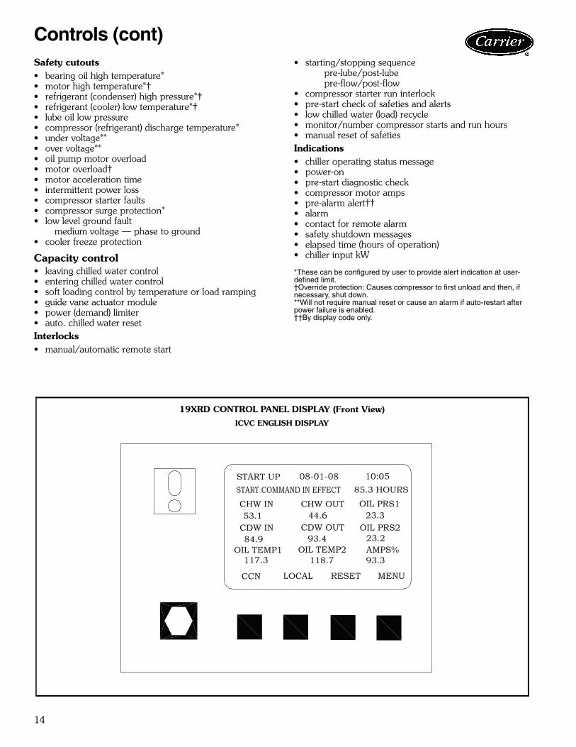
Safety cutouts• bearing oil high temperature*• motor high temperature*†• refrigerant (condenser) high pressure*†• refrigerant (cooler) low temperature*†• lube oil low pressure• compressor (refrigerant) discharge temperature*• under voltage**• over voltage**• oil pump motor overload• motor overload†• motor acceleration time• intermittent power loss• compressor starter faults• compressor surge protection*• low level ground fault
medium voltage — phase to ground• cooler freeze protection
Capacity control• leaving chilled water control• entering chilled water control• soft loading control by temperature or load ramping• guide vane actuator module• power (demand) limiter• auto. chilled water resetInterlocks• manual/automatic remote start
• starting/stopping sequencepre-lube/post-lubepre-flow/post-flow
• compressor starter run interlock• pre-start check of safeties and alerts• low chilled water (load) recycle• monitor/number compressor starts and run hours• manual reset of safetiesIndications• chiller operating status message• power-on• pre-start diagnostic check• compressor motor amps• pre-alarm alert††• alarm• contact for remote alarm• safety shutdown messages• elapsed time (hours of operation)• chiller input kW
*These can be configured by user to provide alert indication at user-defined limit.†Override protection: Causes compressor to first unload and then, if necessary, shut down.**Will not require manual reset or cause an alarm if auto-restart after power failure is enabled.††By display code only.
19XRD CONTROL PANEL DISPLAY (Front View)
ICVC ENGLISH DISPLAY
Controls (cont)

15
19XRD INSIDE PANEL COVER
19XRD CONTROL PANEL COMPONENT LAYOUT
a19-1594ef
a19-1595ef
LEGENDCB — Circuit BreakerCCM — Chiller Control ModuleICVC — International Chiller
Visual Control

16
15
12
15
1415
13
16
2
1
1#
8#
4#5#
6#
8#8# 7# 9#
OIL PUMPPOWER
MAINPOWER
CHILLEDWATER PUMP
CONDENSERWATER PUMP
COOLINGTOWER FAN
10#
10#
TO COOLING
TOWER
DRAIN
34
34 5
6
7
8
9
8
10
5
6
11
FROM
BUILDING
TO BUILDING
FROM COOLING
TOWER
LEGEND
1 — Circuit Breaker2 — Freestanding Starter3 — Compressor Motor Terminal Box4 — Power Panel5 — Pressure Gage6 — Strainer7 — Condenser Water Pump8 — Control Panel9 — Communication Wire
10 — Vent11 — Chilled Water Pump12 — Chilled Water Pump Starter13 — Condenser Water Pump Starter14 — Cooling Tower Fan Starter15 — Circuit Breaker16 — Oil Pump Circuit Breaker
Piping
Control Wiring
Power Wiring
NOTES:1. Wiring and piping shown are for general point-of-
connection only and are not intended to showdetails for a specific installation. Certified field wir-ing and dimensional diagrams are available onrequest.
2. All wiring must comply with applicable codes.
19XRD CHILLER WITH FREE-STANDING STARTER
WIRING LEGEND
WIRENUMBER DESCRIPTION SPECIFICATION
1# Power Supply
3 Phase High/Medium Voltage Main Power Supply WireGround Wire3 Ph / 50 Hz / 346 to 440 V / 10A or3 Ph / 60 Hz / 380 to 460 V / 10A Oil Pump Power Supply
4# Starter to Cooling Tower Fan Starter 4 Pieces Control Wire (Field-installed, if required)
5#Starter to Condenser Water Pump Starter
2 Pieces Control Wire (Field-installed, if required)
6#Starter to Chilled Water Pump Starter
2 Pieces Control Wire (Field-installed, if required)
7# Starter to Oil Heater Contactor See auxiliary ratings
8# Starter to Oil Pump Contactor See auxiliary ratings
9# Starter to Power Panel Contactor 2 Sets 600V Shielded Wire
10# Starter to Motor 2 Sets of 3 Phase High/Medium Voltage Power Wire1 Piece Ground Wire
a19-1976
Typical piping and wiring

17
19XRD MACHINE FOOTPRINT
a19-1977
Application data

18
19XRD ISOLATION PACKAGE
TYPICAL ISOLATION WITH SOLEPLATE TYPICAL ISOLATION WITHOUT SOLEPLATE
SOLEPLATE DETAIL
NOTES:1. Dimensions in ( ) are in millimeters.2. Standard soleplate package includes 8 soleplates, 32 jacking screws and level-
ing pads. Requires isolation package.3. Jacking screws to be removed after grout has set.4. Thickness of grout will vary, depending on the amount necessary to level chiller.
Use only pre-mixed non-shrinking grout, Ceilcote 748 or Chemrex Embelo 636Plus Grout 636, 0-11/2 (38.1) to 0-21/4 (57) thick.
NOTE: Isolation package includes 8 shear flex pads.
a19-985
a23-46tf
a19-1110tf
Application data (cont)

19
COMPRESSOR ENDDRIVE END
COOLERCOOLER
CONDCOND
1
4
3
2
COMPRESSOR ENDDRIVE END
COOLERCOOLER
CONDCOND
1
2
3
4
19XRD NOZZLE ARRANGEMENTS
NOZZLE-IN-HEAD WATERBOXES
MARINE WATERBOXES
WATERBOX PASS In Out ArrangementCode
Nozzle Diameter (in.)
COOLER 1 1 3 A 18CONDENSER 1 2 4 P 24
WATERBOX PASS In Out ArrangementCode
Nozzle Diameter (in.)
COOLER 1 1 3 A 18CONDENSER 1 2 4 P 24
a19-1985
20
4
1
23
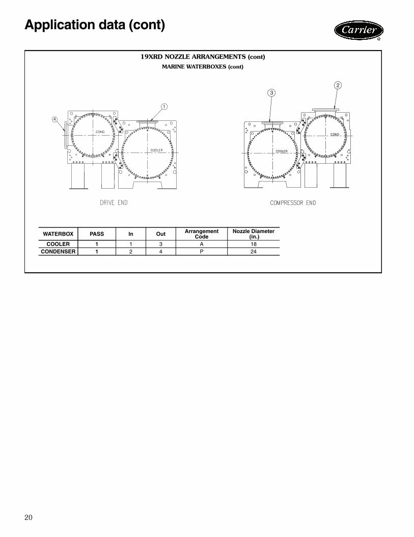
19XRD NOZZLE ARRANGEMENTS (cont)
MARINE WATERBOXES (cont)
WATERBOX PASS In Out ArrangementCode
Nozzle Diameter (in.)
COOLER 1 1 3 A 18CONDENSER 1 2 4 P 24
a19-1979
a19-1978
Application data (cont)
21
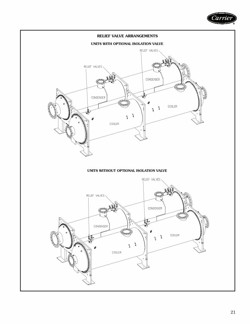
RELIEF VALVE ARRANGEMENTS
UNITS WITH OPTIONAL ISOLATION VALVE
UNITS WITHOUT OPTIONAL ISOLATION VALVE
a19-1981
a19-1980
22
Vent and drain connectionsNozzle-in head waterboxes have vent and drain connec-tions on covers. Marine waterboxes have vent and drainconnections on waterbox shells.
Provide high points of the chiller piping system withvents and the low points with drains. If shutoff valves areprovided in the main water pipes near the unit, a minimalamount of system water is lost when the heat exchangersare drained. This reduces the time required for drainageand saves on the cost of re-treating the system water.
It is recommended that pressure gages be provided atpoints of entering and leaving water to measure pressuredrop through the heat exchanger. Gages may be installedin each waterbox. Pressure gages installed at the vent anddrain connections do not include nozzle pressure losses.
Use a reliable differential pressure gage to measure pres-sure differential when determining water flow. Regulargages of the required pressure range do not have the accu-racy to provide accurate measurement of flow conditions.
ASME stampingAll 19XRD heat exchangers are constructed in accordancewith ASHRAE (American Society of Heating, Refrigerat-ing, and Air Conditioning Engineers) 15 Safety Code forMechanical Refrigeration (latest edition). This code, inturn, requires conformance with ASME (American Societyof Mechanical Engineers) Code for Unfired Pressure Ves-sels wherever applicable. Each heat exchanger is ASME‘U’ stamped on the refrigerant side of each vessel.
Relief valve discharge pipe sizingRelief-valve discharge piping size should be calculated perthe current version of the ASHRAE 15, latest edition.
Carrier further recommends that an oxygen sensor beinstalled to protect personnel. Sensor should be able tosense the depletion or displacement of oxygen in the ma-chine room below 19.5% volume oxygen per ASHRAE15, latest edition.
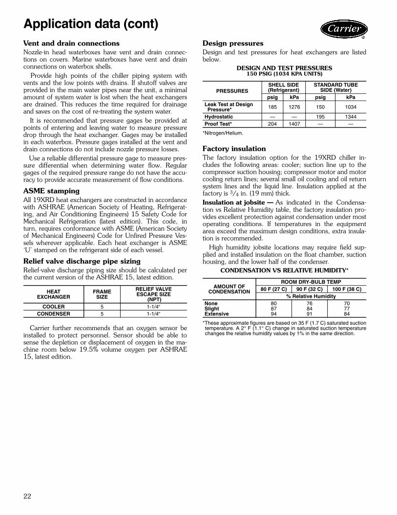
Design pressuresDesign and test pressures for heat exchangers are listedbelow.
DESIGN AND TEST PRESSURES150 PSIG (1034 KPA UNITS)
*Nitrogen/Helium.
Factory insulationThe factory insulation option for the 19XRD chiller in-cludes the following areas: cooler; suction line up to thecompressor suction housing; compressor motor and motorcooling return lines; several small oil cooling and oil returnsystem lines and the liquid line. Insulation applied at thefactory is 3/4 in. (19 mm) thick.Insulation at jobsite — As indicated in the Condensa-tion vs Relative Humidity table, the factory insulation pro-vides excellent protection against condensation under mostoperating conditions. If temperatures in the equipmentarea exceed the maximum design conditions, extra insula-tion is recommended.
High humidity jobsite locations may require field sup-plied and installed insulation on the float chamber, suctionhousing, and the lower half of the condenser.
CONDENSATION VS RELATIVE HUMIDITY*
*These approximate figures are based on 35 F (1.7 C) saturated suctiontemperature. A 2° F (1.1° C) change in saturated suction temperaturechanges the relative humidity values by 1% in the same direction.
HEATEXCHANGER
FRAMESIZE
RELIEF VALVEESCAPE SIZE
(NPT)COOLER 5 1-1/4
CONDENSER 5 1-1/4
PRESSURESSHELL SIDE(Refrigerant)
STANDARD TUBESIDE (Water)
psig kPa psig kPaLeak Test at Design Pressure* 185 1276 150 1034
Hydrostatic — — 195 1344Proof Test* 204 1407 — —
AMOUNT OFCONDENSATION
ROOM DRY-BULB TEMP80 F (27 C) 90 F (32 C) 100 F (38 C)
% Relative HumidityNone 80 76 70Slight 87 84 77Extensive 94 91 84
Application data (cont)

23
FACTORYINSTALLED
FIELD SUPPLIED AND INSTALLEDINSULATION (IF REQUIRED)
19XRD FACTORY-INSTALLED THERMAL INSULATION AREA
a19-1984
a19-1983
a19-1982

24
Packaged Hermetic Centrifugal Liquid ChillerHVAC Guide SpecificationsSize Range:
2500 to 3000 Tons (8790 to 10548 kW) Nominal
Carrier Model Number: 19XRD
Part 1 — General1.01 SYSTEM DESCRIPTION
A. Microprocessor-controlled liquid chiller shall use asingle stage, semi-hermetic centrifugal compressorusing refrigerant HFC-134a. Chiller shall consist oftwo compressors and two individual refrigerantcycles which shall increase redundancy.
B. If a manufacturer proposes a liquid chiller usingHCFC-123 refrigerant, then the manufacturer shallinclude in the chiller price:
1. A vapor activated alarm system shall be capableof responding to HCFC-123 levels of 10 ppmAllowable Exposure Limit (AEL).
2. External refrigerant storage tank and pumpoutunit.
3. Zero emission purge unit capable of operatingeven when the chiller is not operating.
4. Back-up relief valve to rupture disk.5. Chiller pressurizing system to prevent leakage
of noncondensables into chiller during shut-down periods.
6. Plant room ventilation.1.02 QUALITY ASSURANCE
A. Chiller performance shall be rated in accordancewith AHRI Standard 550/590, latest edition.
B. Equipment and installation shall be in compliancewith ANSI/ASHRAE 15 (latest edition).
C. Cooler and condenser refrigerant side shall bedesigned and compliant with ASME Section VIII,division 1 code for unfired pressure vessels.
D. Unit shall be certified in accordance with ISO 9001manufacturing quality standard.
E. Chiller shall be designed and constructed to meetUL listing (below 6 kV) requirements.
F. Centrifugal compressor impellers shall be dynami-cally balanced and over-speed tested by the manu-facturer at a minimum of 120% design operatingspeed. Each compressor assembly shall undergo amechanical run-in test to verify vibration levels, oilpressures, and temperatures are within acceptablelimits.Each compressor assembly shall be proof tested at aminimum 204 psig (1406 kPa) and leak tested at185 psig (1276 kPa) with a tracer gas mixture.
G. Entire chiller assembly shall be proof tested at204 psig (1406 kPa) and leak tested at 185 psig(1276 kPa) with a tracer gas mixture on the
refrigerant side. The water side of each heatexchanger shall be hydrostatically tested at 1.3 timesrated working pressure.
H. Prior to shipment, the chiller automated controlstest shall be executed to check for proper wiring andensure correct controls operation.
I. The 19XRD selection program shall be rated inaccordance with AHRI Standard 550/590, latestedition.
1.03 DELIVERY, STORAGE AND HANDLINGA. Unit shall be stored and handled in accordance with
manufacturer's instructions.B. Unit shall be shipped with all refrigerant piping and
control wiring factory installed.C. Unit shall be shipped charged with oil and full
charge of refrigerant HFC-134a or a nitrogen hold-ing charge as specified on the equipment schedule.
D. Unit shall be shipped with firmly attached labels thatindicate name of manufacturer, chiller model num-ber, chiller serial number, and refrigerant used.
E. Unit shall be shipped in either modular configuration(2 pieces for field-assembly) or integrated configura-tion (one piece assembled).
F. If the chiller is to be exported, the unit shall be suffi-ciently protected from the factory against sea watercorrosion to be suitable for shipment in a standardopen top, ocean shipping container (if chiller is tobe disassembled only).
1.04 WARRANTY (U.S. and Canada Only)Warranty shall include parts and labor for one yearafter start-up or 18 months from shipment, which-ever occurs first. A refrigerant warranty shall be pro-vided for a period of five years.
Part 2 — Products2.01 EQUIPMENT
A. General:Factory assembled liquid chiller shall consist com-pressor, motor, lubrication system, cooler, con-denser, initial oil charge, microprocessor controlsystem, and documentation required prior to start-up.
B. Compressor:1. Two centrifugal compressors of the high perfor-
mance, single-stage type.2. Compressor, motor, and transmission shall be
hermetically sealed into a common assemblyand arranged for easy field servicing.
3. Internal compressor parts must be accessiblefor servicing without removing the compressorbase from the chiller. Connections to the com-pressor casing shall use O-rings instead of gas-kets to reduce the occurrence of refrigerantleakage. Connections to the compressor shallbe flanged or bolted for easy disassembly.
Guide specifications
25
4. Pressure transducers shall be capable of fieldcalibration to ensure accurate readings and toavoid unnecessary transducer replacement.Transducers shall be serviceable without theneed for refrigerant charge removal orisolation.
5. Transmission shall be single ratio, single helical,parallel shaft speed increaser. Gears shall con-form to AGMA Standards, Quality II.
6. Roller element bearings shall be of the steelbacked babbitt lined type. The thrust bearingshall be tilting pad or rolling element type.
7. Centrifugal compressors shall use variable inletguide vanes to provide capacity modulationwhile also providing pre-whirl of the refrigerantvapor entering the impeller for more efficientcompression at all loads.
8. Centrifugal compressors shall be provided witha factory-installed lubrication system to deliveroil under pressure to bearings and transmission.Included in the system shall be:a. Hermetic driven rotary vane oil pump with
factory-installed motor contactor with over-load protection.
b. Refrigerant-cooled oil cooler.c. Oil pressure regulator.d. Oil filter with isolation valves to allow filter
change without removal of refrigerant charge.e. Oil sump heater controlled from unit
microprocessor.f. Oil reservoir temperature sensor with main
control center digital readout.g. Compressor shall be fully field serviceable.
9. Split ring diffuser shall be designed for opera-tion at normal and high lift conditions.
C. Motor:1. Compressor motor shall be of the semi-
hermetic, liquid refrigerant cooled, squirrelcage, induction type suitable for voltage shownon the equipment schedule.
2. If an open drive motor is provided, a compres-sor shaft seal leakage containment system shallbe provided:a. An oil reservoir shall collect oil and refriger-
ant that leaks past the seal.b. A float device shall be provided to open
when the reservoir is full, directing therefrigerant/oil mixture back into the com-pressor housing.
c. A refrigerant sensor shall be located next tothe open drive seal to detect leaks.
3. Motors shall be suitable for operation in arefrigerant atmosphere and shall be cooled byatomized refrigerant in contact with the motorwindings.
4. Motor stator shall be arranged for service orremoval with only minor compressordisassembly and without removing main refrig-erant piping connections.
5. Full load operation of the motor shall notexceed nameplate rating.
6. One motor winding temperature sensor (andone spare) shall be provided.
7. Should the mechanical contractor choose toprovide a chiller with an open motor instead ofthe specified semi-hermetic motor, the contrac-tor shall install additional cooling equipment todissipate the motor heat as per the followingformula:
Btuh = (FLkW motor) (0.05) (3413)Btuh = (FLkW motor) (171)and, alternatelyTons = Btuh / 12,000
The additional piping, valves, air-handlingequipment, insulation, wiring, switchgearchanges, ductwork, and coordination with othertrades shall be the responsibility of the mechan-ical contractor. Shop drawings reflecting anychanges to the design shall be included in thesubmittal, and incorporated into the finalas-built drawings for the project.
8. Also, if an open motor is provided, a mechani-cal room thermostat shall be provided andset at 104 F (40 C). If this temperature isexceeded, the chillers shall shut down and analarm signal shall be generated to the centralEnergy Management System (EMS) displaymodule prompting the service personnel todiagnose and repair the cause of the over tem-perature condition. The mechanical contractorshall be responsible for all changes to thedesign, including coordination with temperaturecontrol, electrical and other trades. In addition,the electrical power consumption of any auxil-iary ventilation and/or mechanical coolingrequired to maintain the mechanical room con-ditions stated above shall be considered in thedetermination of conformance to the scheduledchiller energy efficiency requirement.
D. Cooler and Condenser:1. Cooler shall be of shell and tube type construc-
tion with single pass. Units shall be fabricatedwith high-performance tubing, steel shell, andtube sheets with fabricated steel waterboxes.a. Waterbox shall be nozzle-in-head waterbox
(150 psig).b. Waterbox shall have standard nozzle flange
compliant with ASME.2. Condenser shall be of shell and tube type con-
struction with single pass. Units shall be fabri-cated with high-performance tubing, steel shell,and tube sheets with fabricated steel water-boxes.
26
a. Waterbox shall be nozzle-in-head type water-box (150 psig).
b. Waterbox shall have standard nozzle flangecompliant with ASME.
3. Waterboxes shall have vents, drains, and coversto permit tube cleaning within the space shownon the drawings. A thermistor type temperaturesensor shall be factory installed in each waternozzle.
4. Tubes shall be individually replaceable from theend of the heat exchanger without affecting thestrength and durability of the tube sheet andwithout causing leakage in adjacent tubes.
5. Tubing shall be copper, high-efficiency type,with integral internal and external enhance-ment unless otherwise noted. Tubes shall benominal 3/4-in. OD with nominal wall thicknessof 0.025 in. measured where the tubes are incontact with the end tube sheets unless other-wise noted. Tubes shall be rolled into tubesheets and shall be individually replaceable.Tube sheet holes shall be double grooved forjoint structural integrity.
6. Cooler shall be designed to prevent liquid refrig-erant from entering the compressor via spaceelimination (spacing between top of evaporatoror cooler tubing and suction elbow). Devicesthat introduce pressure losses (such as misteliminators) shall not be acceptable becausethey are subject to structural failures that canresult in extensive compressor damage.
7. The condenser shell shall include a FLASC(flash subcooler) which cools the condensed liq-uid refrigerant to a reduced temperature,thereby increasing the refrigeration cycleefficiency.
8. A relief valve shall be installed on each heatexchanger.
E. Refrigerant Flow Control:1. To improve part load efficiency, liquid refriger-
ant shall be metered from the condenser to thecooler using a float-type metering valve tomaintain the proper liquid level of refrigerant inthe heat exchangers under both full and partload operating conditions.
2. The float valve chamber shall have a boltedaccess cover to allow field inspection and thefloat valve shall be field serviceable.
F. Controls, Safeties, and Diagnostics:1. Controls:
a. The chiller shall be provided with a factoryinstalled and wired microprocessor controlcenter. The control center shall include a16-line by 40-character liquid crystal display,4 function keys, stop button, and alarmlight. The microprocessor can be configuredfor either English or SI units. The chillercontrol shall consist of two individual ICVC
(international chiller visual control) devicesand is programmed for lead-lag operation.
b. All chiller and starter monitoring shall be dis-played at the chiller control panel.
c. The controls shall make use of non-volatilememory.
d. The chiller control system shall have the abil-ity to interface and communicate directly tothe building control system.
e. The default standard display screen shallsimultaneously indicate the following mini-mum information:1) date and time of day2) 24-character primary system status
message3) 24-character secondary status message4) chiller operating hours5) entering chilled water temperature6) leaving chilled water temperature7) entering condenser water temperature8) leaving condenser water temperature9) oil supply pressure
10) oil sump temperature11) percent motor rated load amps (RLA)
f. In addition to the default screen, statusscreens shall be accessible to view the statusof every point monitored by the control cen-ter including:1) evaporator pressure2) condenser pressure3) bearing oil supply temperature4) compressor discharge temperature5) motor winding temperature 6) number of compressor starts7) control point settings8) discrete output status of various devices9) compressor motor starter status
10) optional spare input channels11) line current and voltage for each phase12) frequency, kW, kW-hr, demand kW
g. Schedule Function:The chiller controls shall be configurable formanual or automatic start-up and shutdown.In automatic operation mode, the controlsshall be capable of automatically starting andstopping the chiller according to a storeduser programmable occupancy schedule.The controls shall include built-in provisionsfor accepting:1) A minimum of two 365-day occupancy
schedules.2) Minimum of 8 separate occupied/
unoccupied periods per day.3) Daylight savings start/end.4) 18 user-defined holidays.5) Means of configuring an occupancy
timed override.6) Chiller start-up and shutdown via remote
contact closure.
Guide specifications (cont)

27
h. Service Function:The controls shall provide a password pro-tected service function which allows autho-rized individuals to view an alarm history filewhich shall contain the last 25 alarm/alertmessages with time and date stamp. Thesemessages shall be displayed in text form, notcodes.
i. Dual Compressor Control:The control system shall cycle the chillers ina manner to maintain optimal chiller effi-ciency while properly maintaining the leav-ing chiller set point. The sequencing of thecompressors shall be configurable by theuser. The control system shall allow opera-tion of one compressor when the other com-pressor is powered off for service.
j. Network Window Function:Each chiller control panel shall be capable ofviewing multiple point values and statusesfrom other like controls connected on acommon network, including controller main-tenance data. The operator shall be able toalter the remote controller’s set points ortime schedule and to force point values orstatuses for those points that are operatorforcible. The control panel shall also haveaccess to the alarm history file of all like con-trollers connected on the network.
k. Pump Control:Upon request to start the compressor, thecontrol system shall start the chilled waterpump, condenser water pumps and verifythat flows have been established.
l. Ramp Loading:A user-configurable ramp loading rate, effec-tive during the chilled water temperaturepulldown period, shall control the rate ofguide vane opening to prevent a rapidincrease in compressor power consumption.The controls shall allow configuration of theramp loading rate in either degrees/minuteof chilled water temperature pulldown orpercent motor amps/minute. During theramp loading period, a message shall be dis-played informing the operator that thechiller is operating in ramp loading mode.
m. Chilled Water Reset:The control center shall allow reset of thechilled water temperature set point based onany one of the following criteria:1) Chilled water reset based on an external
4 to 20 mA signal.2) Chilled water reset based on a remote
temperature sensor (such as outdoorair).
3) Chilled water reset based on water tem-perature rise across the evaporator.
n. Demand Limit:The control center shall limit amp draw ofthe compressor to the rated load amps or toa lower value based on one of the followingcriteria:1) Demand limit based on a user input
ranging from 40% to 100% of compres-sor rated load amps.
2) Demand limit based on external 4 to20 mA signal.
o. Controlled Compressor Shutdown:The controls shall be capable of being con-figured to soft stop the compressor. Whenthe stop button is pressed or remote con-tacts open with this feature active, the guidevanes shall close to a configured amperagelevel and the machine shall then shut down.The display shall indicate “shutdown in prog-ress.”
2. Safeties:a. Unit shall automatically shut down when any
of the following conditions occur: (Each ofthese protective limits shall require manualreset and cause an alarm message to be dis-played on the control panel screen, inform-ing the operator of the shutdown cause.)1) motor overcurrent2) over voltage*3) under voltage*4) single cycle dropout*5) bearing oil high temperature6) low evaporator refrigerant temperature7) high condenser pressure8) high motor temperature9) high compressor discharge temperature
10) low oil pressure11) prolonged surge12) loss of cooler water flow13) loss of condenser water flow14) starter fault*Shall not require manual reset or cause analarm if auto-restart after power failure isenabled.
b. The control system shall detect conditionsthat approach protective limits and take self-corrective action prior to an alarm occur-ring. The system shall automatically reducechiller capacity when any of the followingparameters are outside their normal operat-ing range:1) high condenser pressure2) high motor temperature3) low evaporator refrigerant temperature4) high motor amps.
Manufacturer reserves the right to discontinue, or change at any time, specifications or designs without notice and without incurring obligations.Pg 28 Printed in U.S.A. Form 19XRD-3PD
Replaces: New
Carrier Corporation • Syracuse, New York 13221 7-11
c. During the capacity override period, a pre-alarm (alert) message shall be displayedinforming the operator which condition iscausing the capacity override. Once thecondition is again within acceptable limits,the override condition shall be terminatedand the chiller shall revert to normal chilledwater control. If during either condition theprotective limit is reached, the chiller shallshut down and a message shall be dis-played informing the operator which con-dition caused the shutdown and alarm.
d. Internal built-in safeties shall protect thechiller from loss of water flow. Differentialpressure switches shall not be allowed to bethe only form of freeze protection.
3. Diagnostics and Service:a. A self diagnostic controls test shall be an
integral part of the control system to allowfor quick identification of malfunctioningcomponents.
b. Once the controls test has been initiated,all pressure and temperature sensors shallbe checked to ensure they are within nor-mal operating range. A guide vane actuatortest shall open and close the guide vanes tocheck for proper operation. The operatormanually acknowledges proper guide vaneoperation prior to proceeding to next test.
c. In addition to the automated controls test,the controls shall provide a manual testwhich permits selection and testing of indi-vidual control components and inputs. Athermistor test and transducer test shall dis-play on the control screen the actual read-ing of each transducer and each thermistorinstalled on the chiller. All out-of-range sen-sors shall be identified.
G. Electrical Requirements:1. Electrical contractor shall supply and install
main electrical power line, disconnectswitches, circuit breakers, and electricalprotection devices per local code requirementsand as indicated necessary by the chillermanufacturer.
2. Electrical contractor shall wire local electricalpower line to the starter and the starter powercircuit to the chiller compressor motor.
3. Electrical contractor shall wire the starter con-trol circuit and chiller power panel control cir-cuit to the chiller control circuit.
4. Electrical contractor shall wire the chilledwater pump, condenser water pump, andtower fan control circuit to the chiller controlcircuit.
5. Electrical contractor shall supply and installelectrical wiring and devices required tointerface the chiller controls with the buildingcontrol system if applicable.
6. Electrical power shall be supplied to the unit atthe voltage, phase, and frequency listed in theequipment schedule.
H. Piping Requirements — Instrumentation andSafeties:
1. Mechanical contractor shall supply and installpressure gages in readily accessible locationsin piping adjacent to the chiller such that theycan be easily read from a standing position onthe floor. Scale range shall be such that designvalues shall be indicated at approximately mid-scale.
2. Gages shall be installed in the entering andleaving water lines of cooler and condenser.
I. Vibration Isolation:1. Chiller manufacturer shall furnish neoprene
isolator pads for mounting equipment on alevel concrete surface.
2. Chiller manufacturer shall also furnish a sole-plate package consisting of soleplates, jackingscrews, leveling pads, and neoprene pads.
J. Start-up:1. The chiller manufacturer shall provide a fac-
tory-trained representative, employed by thechiller manufacturer, to perform the start-upprocedures as outlined in the Start-up, Opera-tion and Maintenance manual provided by thechiller manufacturer.
2. Manufacturer shall supply the following litera-ture:a. Start-up, operation and maintenance
instructions.b. Installation instructions.c. Field wiring diagrams.d. One complete set of certified drawings.
K. Special Features:1. Cooler and Condenser Tubes:
Contact local Carrier representative for othertube offerings.
2. Marine Waterboxes, 150 psig (1034 kPa):Unit manufacturer shall furnish marine stylewaterboxes on cooler and/or condenser ratedat 150 psig (1034 kPa).
3. Optional Compressor Discharge IsolationValve and Liquid Line Ball Valve:These items shall be factory installed to allowisolation of the refrigerant charge in the con-denser for servicing the compressor.
Guide specifications (cont)