product data - dms.hvacpartners.comdms.hvacpartners.com/docs/1009/public/0d/58cv-4pd.pdf · product...
TRANSCRIPT
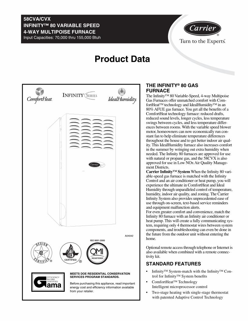
58CVA/CVXINFINITY™ 80 VARIABLE SPEED4-WAY MULTIPOISE FURNACEInput Capacities: 70,000 thru 155,000 Btuh
Product Data
THE INFINITY
®
80 GAS FURNACE
The Infinity™ 80 Variable-Speed, 4-way Multipoise Gas Furnaces offer unmatched comfort with Com-fortHeat™ technology and IdealHumidity™ in an 80% AFUE gas furnace. You get all the benefits of a ComfortHeat technology furnace: reduced drafts, reduced sound levels, longer cycles, less temperature swings between cycles, and less temperature differ-ences between rooms. With the variable speed blower motor, homeowners can now economically run con-stant fan to help eliminate temperature differences throughout the house and to get better indoor air qual-ity. This IdealHumidity furnace also increases comfort in the summer by wringing out extra humidity when needed. The Infinity 80 furnaces are approved for use with natural or propane gas, and the 58CVX is also approved for use in Low NOx Air Quality Manage-ment Districts.
Carrier Infinity™ System
When the Infinity 80 vari-able-speed gas furnace is matched with the Infinity Control and an air conditioner or heat pump, you will experience the ultimate in ComfortHeat and Ideal Humidity through unparalleled control of temperature, humidity, indoor air quality, and zoning. The Carrier Infinity System also provides unprecedented ease of use through on-screen, text-based service reminders and equipment malfunction alerts.For even greater comfort and convenience, match the Infinity 80 furnace with an Infinity air conditioner or heat pump. This will create a fully communicating sys-tem, requiring only 4 thermostat wires between system components, and troubleshooting can even be done in the future from the outdoor unit without entering the home.
Optional remote access through telephone or Internet is also available when combined with a remote connec-tivity kit.
STANDARD FEATURES
•
Infinity™ System-match with the Infinity™ Con-trol for Infinity™ System benefits
•
ComfortHeat™ Technology Intelligent microprocessor control
•
Two-stage heating with single-stage thermostat with patented Adaptive Control Technology
CERTIFIED ®REGISTERED
ISO 9001:2000
ama
MEETS DOE RESIDENTIAL CONSERVATION SERVICES PROGRAM STANDARDS.
Before purchasing this appliance, read important energy cost and efficiency information available from your retailer.
A04042
INFINITY
IdealHumidity

2
58CV
A/C
VX
•
Very low operating sound through low-stage operation and QuieTech™ system
QuieTech™ system noise reduction system
•
Integral part of the IdealHumidity™ System
Maximum dehumidification selec-tion for summer time cooling
Full IdealHumidity benefits includ-ing “Super Dehumidify”
SmartEvap™–Humidity control when using a Thermidistat/Infinity control
Variable-speed blower motor
Super-low electrical use, up to 80 percent less than standard models
Increased SEER ratings for AC and HP systems
Perfectly matches CFM to cooling system at all static points
•
Comfort Fan™–Up to 12 cooling air-flow selections from thermostat with a wide range of capability
•
High-Efficiency Media Filtration Cabinet included
•
Microprocessor based control center
LED diagnostics and self test feature
Stores fault codes during power out-ages
Adjustable heating air temperature rise
Adjustable cooling airflow
Dehumidification selection for sum-mer-time cooling
•
4-way Multipoise furnace, 13 vent applications
•
Compact design - only 33-1/3 in. tall
•
Power Heat™ Igniter
•
Draft Safeguard switch to ensure proper furnace venting
•
Insulated blower compartment
•
Inner door for tighter sealing
•
Hybrid Heat™ compatible
•
All models are chimney friendly when used with accessory vent kit
•
Residential installations eligible for consumer financing through the Re-tail Credit Program
LIMITED WARRANTY
• 20-year warranty on “Super S™” heat exchanger
• 5-year parts warranty on all other components
A02169
A02169 A02170
HEAT EXCHANGER CONTROL BOARD INDUCER BLOWER
BLW
NU
ET
RA
LSTAT
US
CO
DE
LED
SEC-2 SEC-1
EAC-2 L2
FUSE 3-AMP
0.5 AMP@24VAC
HUM
TEST/TWIN
Y1 D
HU
M G
CO
M W
/W1 Y/Y
2 R24V
PLT
120 180
90 150
BLOWER OFF-DELAY
PLT
1
CO
OL H
EA
T
SPARE-1 SPARE-2FAN
EAC-1
1-AMP@
115V AC PR-1
L1
PL2 1
A02215
Model number nomenclature58CVA 070
58CVA Variable Speed 4-Way Multipoise58CVX Low NOx version
Input Capacity070 — 66,000 Btuh 135 — 132,000 Btuh090 — 88,000 Btuh 155 — 154,000 Btuh110 — 110,000 Btuh
100 12
Nominal Cooling Size(Airflow at .5 ESP.)(400 CFM per 12,000 Btuh)12 — 1200 CFM20 — 2000 CFM22 — 2200 CFM
Series Number

3
58C
VA
/CV
X
NOTE:
The 58CVA/CVX Furnaces are factory shipped for use with natural gas. These furnaces can be field-converted for propane gas with a factory-authorized and listed accessory conversion kit.
A04137
INDUCER MOROR ASSEMBLY
PRESSURE SWITCHES
FLUE COLLECTOR
BOX
GAS VALVE
HOT SURFACE IGNITER
MANUAL RESET LIMIT SWITCHES
CONTROL
VENT ELBOW
MAIN LIMIT SWITCH(BEHIND GAS VALVE)
DRAFT SAFEGUARD SWITHCH
BLOWER AND MOTOR
RATING PLATE NOT SHOWN
(LOCATED ON BLOWER DOOR)
GAS MANIFOLD
GAS BURNER
BLOWER DOOR SAFETY SWITCH
FLAME SENSOR
*Elbow may be turned to a different position, dependingon type of installation
Furnace Components

4
58CV
A/C
VX
Carrier accessories
C04008
MECHANICAL OR ELECTRONIC
AIR CLEANERCleans the air of smoke, dirt, and many pollens commonly found. Saves decorating and cleaning expenses by keeping carpets, furniture, and drapes cleaner.
Electronic air cleaner is shown.
ElectronicHigh Efficiency
ON
OFF
Input PowerCell Energized
Air Filtration System
Tur
ly
to prevent e
Electric Shock Hazard
WARNING
!
n OFF remote power before removing any panel
More than one power supply may be present
This equipment should be inpected frequently and collected dirt removed regular
xcessive accumulation that may result in flash over or fire
damage
JAN
FEB
MAR
APR
MAY
JUN
JUL
AUG
SEP
OCT
NOV
DEC
A03149
CONTROLS:THERMOSTATS
AND ZONINGAvailable in programmable and non-programmable models, Carrier thermo-stats maintain a constant, comfortable temperature level in the home.
For the ultimate in home comfort, Carrier’s 2, 4, and 8-zone systems allow tempera-ture control of individual “zones” of the home. This is accomplished through a series of electronic dampers and remote room sensors. Infinity™ Control shown.
A01484
MODEL HUMCCLFPHUMIDIFIER
By adding moisture to winter-dry air, a Carrier humidifier can often improve comfort and keep furniture, rugs, and draperies in better condition. Moisturizing household air also helps to retain normal body heat and provides comfort at lower temperatures.
Accessories
ELECTRONIC AIR CLEANER (EAC) Model EACA
MECHANICAL AIR CLEANER Models EZXCAB, FILCAB
HUMIDIFIER Model HUM
HEAT RECOVERY VENTILATOR Model HRV
ENERGY RECOVERY VENTILATOR Model ERV
THERMOSTAT–NON-PROGRAMMABLE
Auto Changeover, °F/°C, 1-Stage Heat/1-Stage Cool - TSTATCCNAC01-B
Auto Changeover, °F/°C, 2-Stage Heat/1-Stage Cool - TSTATCCNHP01-B
Auto Changeover, °F/°C, 2-Stage Heat/2-Stage Cool - TSTATCCN2S01-B
in AC Mode, 3-Stage Heat/2-Stage Cool in HP Mode
Air Conditioner, 1-Stage Heat/1-Stage Cool, Manual Changeover, °F/°C - TSTATCCBAC01
THERMOSTAT–PROGRAMMABLE
Auto Changeover, 7-Day Programmable, °F/°C, 1-Stage Heat/1-Stage Cool-TSTATCCPAC01-B
Auto Changeover, 7-Day Programmable, °F/°C, 2-Stage Heat/1-Stage Cool - TSTATCCPHP01-B
Auto Changeover, 7-Day Programmable, °F/°C, 2-Stage Heat/1-Stage Cool - TSTATCCP2S01-B
in AC Mode, 3-Stage Heat/2-Stage Cool in HP Mode
Dual Fuel Thermostat Includes Outdoor Air Temperature Sensor -TSTATCCPDF01-B
Thermidistat Control - Non-Programmable/Programmable Thermostat -TSTATCCPRH01-B
with Humidity Control (For use in Dual Fuel, AC, HP, and 2S applications, includes Outdoor Air
Temperature Sensor)
ZONING - 2 ZONE ZONE CC2KIT01-B, ZONE KIT2ZCAR
ZONING - 4 ZONE ZONECC4KIT01-B
ZONING - 8 ZONE ZONECC8KIT01-B
INFINITY CONTROL
Infinity ™ Control Deluxe 7-Day Programmable (Wall-mounted system control.) - SYSTXCCUID01
Inifity™ Control Deluxe Zoning 7-Day Programmable (Wall-mounted control for a multi-zone system.) - SYSTXCCUIZ01
Infinity™ 4-Zone Damper Control Module (Wall-mounted for a 4-zone system.) - SYSTXCC4ZC02
Infinity™ Smart Sensor (Optional wall control used to monitor temperature and/or fan control in an individual zone.) - SYSTXCCSMS01
Infinity™ Remote Room Sensor (Monitors temperature in an individual zone.) - SYSTXCCRRS01
Infinity™ System Access Module (Hardware for wireless access and control via phone or internet.) - SYSTXCCSAM01
Infinity™ Network Interface Module (Connects Heat Recovery and Energy Recovery Ventilators or older two-speed outdoor models to system.) - SYSTCCNIM01†
Decorative Back Plate for Infinity Control (Decorative wall plate.) - SYSTXXXBPU01
* When applied with Carrier’s IdealHumidity series 58MVP, 58CV(A,X) and FE Indoor Models† Must be installed in Dual-Fuel Infinity system applications.

5
58C
VA
/CV
X
Carrier Accessories
* Factory-authorized, field installed. Fuel conversion kits are AGA/CGA recognized.† Suitable for side return
DESCRIPTION PART NO. 070-12 090-16 110-20 135-22 155-22
Cartridge Media Filter
FILCCCAR0016 X X
FILCCCAR0020 X
FILCCCAR0024 X X
EZ Flex Media Filter with End Caps
EXPXXUNV0016 X X
EXPXXUNV0020 X
EXPXXUNV0024 X X
Replacement EZ Flex Filter Media
EXPXXFIL0016 X X
EXPXXFIL0020 X
EXPXXFIL0024 X X
External Bottom Return Filter Rack
KBAFR0401B14 X
KGAFR0501B17 X
KGAFR0601B21 X
KGAFR0701B24 X X
External Side Return Filter Rack KGAFR0801SRE X X X X X
Unframed Filter 1-in.
KGAWF1306UFR X X S† S† S†
KGAWF1406UFR X
KGAWF1506UFR X X
Flue Extension KGAFE0112UPH X X X X X
Combustible Floor Base KGASB0201ALL X X X X X
Downflow Vent Guard KGAVG0101DFG X X X X X
Vent Extension Kit KGAVE0101DNH X X X X X
Chimney Adapter Kit KGACA02014FC X X X
Chimney Adapter Kit KGACA02015FC X X
Natural-to-Propane Conversion Kit* KGANP4001ALL X X X X X
Propane-to-Natural Conversion Kit KGAPN3301ALL X X X X X
Label Kit KGALB0101KIT X X X X X
Air Leakage Kit (Qty 10) KGBAC0110DGK X X X X X
ECM Motor Simulator KGASD0201FMS X X X X X
Advanced Product Monitor KGAFP0201APM X X X X X
Gas Orifice Kit (Qty 50)
KGAHA0150N42
KGAHA0250N43(factory supplied)
KGAHA0350N44
KGAHA0450N45
KGAHA0550N46
KGAHA1550N47
KGAHA1650N48
KGAHA0650P54
KGAHA0750P55
See Installation Instructions for model, altitude, and heat value usages.
6
58CV
A/C
VX
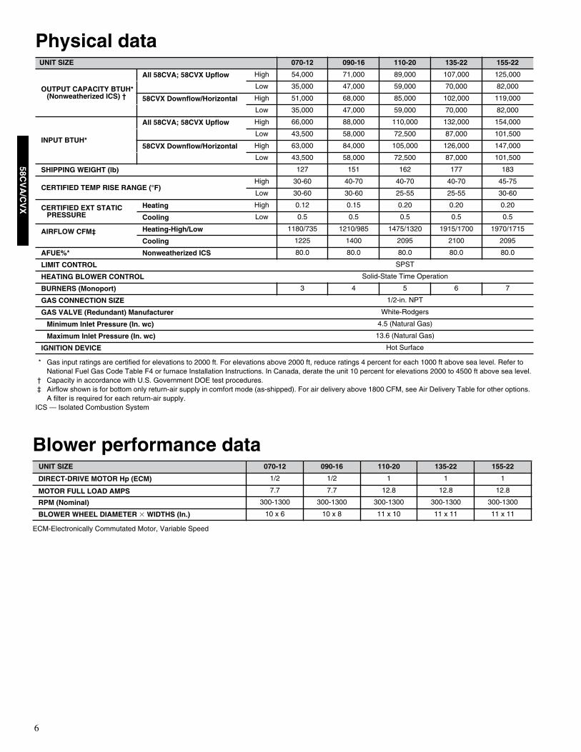
Physical data
* Gas input ratings are certified for elevations to 2000 ft. For elevations above 2000 ft, reduce ratings 4 percent for each 1000 ft above sea level. Refer to National Fuel Gas Code Table F4 or furnace Installation Instructions. In Canada, derate the unit 10 percent for elevations 2000 to 4500 ft above sea level.
† Capacity in accordance with U.S. Government DOE test procedures.‡ Airflow shown is for bottom only return-air supply in comfort mode (as-shipped). For air delivery above 1800 CFM, see Air Delivery Table for other options.
A filter is required for each return-air supply.ICS — Isolated Combustion System
UNIT SIZE 070-12 090-16 110-20 135-22 155-22
OUTPUT CAPACITY BTUH*(Nonweatherized ICS) †
All 58CVA; 58CVX Upflow
High 54,000 71,000 89,000 107,000 125,000
Low 35,000 47,000 59,000 70,000 82,000
58CVX Downflow/Horizontal
High 51,000 68,000 85,000 102,000 119,000
Low 35,000 47,000 59,000 70,000 82,000
INPUT BTUH*
All 58CVA; 58CVX Upflow
High 66,000 88,000 110,000 132,000 154,000
Low 43,500 58,000 72,500 87,000 101,500
58CVX Downflow/Horizontal
High 63,000 84,000 105,000 126,000 147,000
Low 43,500 58,000 72,500 87,000 101,500
SHIPPING WEIGHT (lb)
127 151 162 177 183
CERTIFIED TEMP RISE RANGE (°F)
High 30-60 40-70 40-70 40-70 45-75
Low 30-60 30-60 25-55 25-55 30-60
CERTIFIED EXT STATIC PRESSURE
Heating
High 0.12 0.15 0.20 0.20 0.20
Cooling
Low 0.5 0.5 0.5 0.5 0.5
AIRFLOW CFM‡ Heating-High/Low
1180/735 1210/985 1475/1320 1915/1700 1970/1715
Cooling
1225 1400 2095 2100 2095
AFUE%* Nonweatherized ICS
80.0 80.0 80.0 80.0 80.0
LIMIT CONTROL
SPST
HEATING BLOWER CONTROL
Solid-State Time Operation
BURNERS (Monoport)
3 4 5 6 7
GAS CONNECTION SIZE
1/2-in. NPT
GAS VALVE (Redundant) Manufacturer
White-Rodgers
Minimum Inlet Pressure (In. wc)
4.5 (Natural Gas)
Maximum Inlet Pressure (In. wc)
13.6 (Natural Gas)
IGNITION DEVICE
Hot Surface
Blower performance data
ECM-Electronically Commutated Motor, Variable Speed
UNIT SIZE 070-12 090-16 110-20 135-22 155-22
DIRECT-DRIVE MOTOR Hp (ECM)
1/2 1/2 1 1 1
MOTOR FULL LOAD AMPS
7.7 7.7 12.8 12.8 12.8
RPM (Nominal)
300-1300 300-1300 300-1300 300-1300 300-1300
BLOWER WHEEL DIAMETER
�
WIDTHS (In.)
10 x 6 10 x 8 11 x 10 11 x 11 11 x 11
7
58C
VA
/CV
X
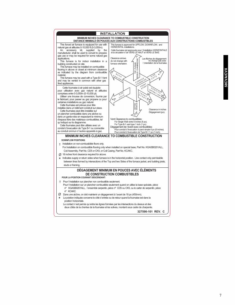
MINIMUM INCHES CLEARANCE TO COMBUSTIBLE CONSTRUCTIONDISTANCE MINIMALE EN POUCES AUX CONSTRUCTIONS COMBUSTIBLES
INSTALLATION
327590-101 REV. C
Ø
*
Clearance arrowsdo not change withfurnace orientation.
BO
TTO
MD
ES
SO
US
0"
3" 0"
0"
1"
0"
24"MIN
S I DE
C Ô T ÉF R O N T
A V A N T
BC K
A R R I È
A
ER
S E R VIEC
ENTRTE
NEI
VANA
TFRONT
S IE
C Ô T È
F OUUF
RN ACS
EE
IARN
Ø
TO
P /
PLE
NU
MD
ES
SU
S /
CH
AM
BR
ED
'AIR
D *
*
†
MIN
Ø
*
†
This forced air furnace is equipped for use with natural gas at altitudes 0-10,000 ft (0-3,050m).
An accessory kit, supplied by themanufacturer, shall be used to convert to propanegas use or may be required for some natural gasapplications.
This furnace is for indoor installation in abuilding constructed on site.
This furnace may be installed on combustibleflooring in alcove or closet at minimum clearanceas indicated by the diagram from combusitblematerial.
This furnace may be used with a Type B-1 Ventand may be vented in common with other gasfired appliances.
Cette fournaise à air pulsé est équipéepour utilisation avec gaz naturel et altitudescomprises entre 0-3,050m (0-10,000 pi).
Utiliser une trousse de conversion, fournie parle fabricant, pour passer au gaz propane ou pourcertaines installations au gaz naturel.
Cette fournaise est prévue pour êtreinstallée dans un bâtiment construit sur place.
Cette fournaise peut être installée surun plancher combustible dans une alcôve oudans un garde-robe en respectant le minimumd'espace libre des matériaux combustibles, telqu indiqué sur le diagramme.
Cette fournaise peut être utilisée avec unconduit d´évacuation de Type B-1 ou connectéeau conduit ommun d 'autres appareils à gaz.
MINIMUM INCHES CLEARANCE TO COMBUSTIBLE CONSTRUCTION
Installation on non-combusibible floors only.For Installation on combustible flooring only when installed on special base, Part No. KGASB0201ALL,Coil Assembly, Part No. CD5 or CK5, or Coil Casing, Part No. KCAKC.
18 inches front clearance required for alcove.Indicates supply or return sides when furnace is in the horizontal position. Line contact only permissiblebetween lines formed by intersections of the Top and two Sides of the furnace jacket, and building joists,studs or framing.
DOWNFLOW POSITIONS:
DÉGAGEMENT MINIMUM EN POUCES AVEC ÉLÉMENTS DE CONSTRUCTION COMBUSTIBLES
Pour l installation sur plancher non combustible seulement.Pour l installation sur un plancher combustible seulement quand on utilise la base spéciale, piècenº KGASB0201ALL, l ensemble serpentin, pièce nº CD5 ou CK5, ou le carter de serpentin, piècenº KCAKC.
Dans une alcôve, on doit maintenir un dégagement à l avant de 18 po (450mm).La poistion indiquée concerne le côté d´entrée ou de retour quand la fournaise est dans laposition horizontale.
Le contact n´est permis qu´entre les lignes formées par les intersections du dessus et des deux côtés de la cherrise de la fournaise et les solives, montant sous cadre de charpente.
POUR LA POSITION COURANT DESCENDANT:
Cette fournaise est approuvée pour l 'installation HORIZONTALEet la circulation d 'air VERS LE HAUT et VERS LE BAS.
This furnace is approved for UPFLOW, DOWNFLOW, andHORIZONTAL installations.
Clearance in inchesDégagement (po).
Les fléches de dégagementne change pas avec
l 'orientation de la fournaise.
Vent Clearance to combustibles:For Single Wall vents 6 inches (6 po).For Type B-1 vent type 1 inch (1 po).
Dégagement de l évent avec combustibles:Pour conduit d´évacuation à paroi simple 6 po (6 inches).Pour conduit d´évacuation de Type B-1 1 po (1 inch).
†
8
58CV
A/C
VX
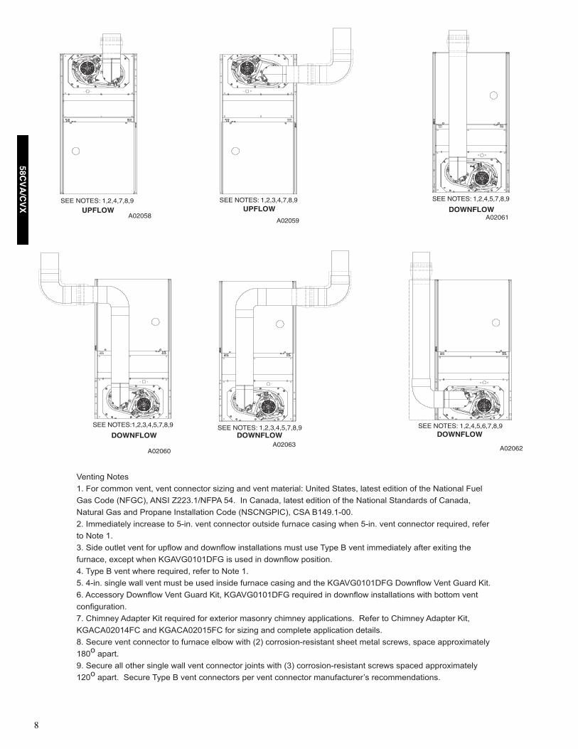
A02058
SEE NOTES: 1,2,4,7,8,9
UPFLOWA02059
SEE NOTES: 1,2,3,4,7,8,9UPFLOW
A02061
SEE NOTES: 1,2,4,5,7,8,9
DOWNFLOW
A02060
SEE NOTES:1,2,3,4,5,7,8,9
DOWNFLOW
A02062
SEE NOTES: 1,2,4,5,6,7,8,9DOWNFLOW
A02063
SEE NOTES: 1,2,3,4,5,7,8,9DOWNFLOW
�
������� ���
�� � ���� ����� ���� ������� ����� ��� ���� ��������� ������ ������ ����� ������ � ��� ������� ���
�� ��� �� �� � !��" #$$%��&� '! ()� "� ������� ����� ������ � ��� ������� �������� � �������
������� �� ��� '�*��� "��������� ��� ������'"� � ��! +�),��-..�
$� "���������/ ������� � (-��� ���� ������� ����� ������� ����� 0��� (-��� ���� ������� ��1������ �����
� ��� ��
%� ���� ����� ���� �� �*��0 ��� �0���0 ���������� ��� �� 2/*� + ���� ����������/ ����� �3����� ���
�������� �3��*� 0��� 4�!��.�.�5 � � ��� �� �0���0 *�����
)� 2/*� + ���� 0���� ��1������ ����� � ��� ��
(� )-��� ����� 0��� ���� ��� 6� ��� ����� ������� ����� ��� ��� 4�!��.�.�5 � 50���0 ���� ����� 4���
7� !����/ 50���0 ���� ����� 4��� 4�!��.�.�5 � ��1����� �� �0���0 ���������� 0��� 6��� ����
������������
8� ������/ !��*��� 4�� ��1����� �� �3����� ����/ ������/ �**�������� 9���� � ������/ !��*��� 4���
4�!�!.$.�) � ��� 4�!�!.$.�( � �� ����� ��� ��*���� �**������� �������
:� ������ ���� ������� � ������� ��60 0��� �$ �����-������� ���� ����� ���0� *��� �**�3������/
�:.
�*����
,� ������ ��� ���� ����� 0��� ���� ������� ;��� 0��� �% �����-������� ���0 *���� �**�3������/
�$.
�*���� ������ 2/*� + ���� ������� *�� ���� ������� ������������< �������������

9
58C
VA
/CV
X
A02068
SEE NOTES: 1,2,4,5,7,8,9HORIZONTAL RIGHT
A02070
SEE NOTES: 1,2,4,5,7,8,9HORIZONTAL RIGHT
A02069
SEE NOTES: 1,2,4,7,8,9HORIZONTAL RIGHT
A02064
SEE NOTES: 1,2,4,7,8,9
HORIZONTAL LEFTA02065
SEE NOTES: 1,2,4,5,7,8,9HORIZONTAL LEFT
A02066
SEE NOTES: 1,2,4,5,7,8,9HORIZONTAL LEFT
A02067
SEE NOTES: 1,2,4,5,7,8,9
HORIZONTAL LEFT

10
58CV
A/C
VX
UUUU nnnn iiii tttt OOOOppppeeeerrrraaaattttiiiinnnngggg MMMMooooddddeeee CCCCFFFFMMMM AAAAiiiirrrrfffflllloooowwww EEEExxxxtttteeeerrrrnnnnaaaallll SSSSttttaaaattttiiiicccc EEEExxxxtttteeeerrrrnnnnaaaallll SSSSttttaaaattttiiiicccc PPPPrrrreeeessssssssuuuurrrreeee ((((EEEESSSSPPPP))))SSSS iiii zzzzeeee SSSSeeeettttttttiiiinnnngggg PPPPrrrreeeessssssssuuuurrrreeee RRRRaaaannnnggggeeee**** 0.1 0.2 0.3 0.4 0.5 0.6 0.7 0.8 0.9 1.0
0000 7777 0000 ---- 1111 2222 AAAAIIIIRRRRFFFFLLLLOOOOWWWW ((((CCCCFFFFMMMM))))†† Low Heat 735 (615)† 0-0.50 735 735 735 735 725
High Heat 1180 (1060)† 0-1.0 1160 1165 1175 1180 1180 1180 1180 1180 1180 1175†† 1-1/2 Ton Cooling 525 0-0.50‡ 525 525 525 525 510†† 2-Ton A/C Cooling 700 0-0.50‡ 700 700 700 695 685
2-1/2 Ton A/C Cooling 875 0-1.0‡ 875 875 875 875 875 875 865 855 845 8403-Ton A/C Cooling 1050 0-1.0‡ 1050 1050 1050 1050 1050 1050 1050 1050 1045 10353-1/2 Ton A/C Cooling 1225 0-1.0 1205 1215 1225 1225 1225 1225 1225 1225 1225 1210Maximum 1400 0-1.0 1395 1400 1400 1400 1400 1400 1400 1385 1360 1310
0000 9999 0000 ---- 1111 6666Low Heat 985 (825)† 0-1.0 950 970 985 985 985 985 985 985 985 980High Heat 1210 (1090)† 0-1.0 1190 1205 1210 1210 1210 1210 1210 1210 1210 1200
†† 1-1/2 Ton A/C Cooling 525 0-0.50‡ 525 525 525 525 500†† 2-Ton A/C Cooling 700 0-0.50‡ 690 695 700 700 690
2-1/2 Ton A/C Cooling 875 0-1.0‡ 830 855 875 875 875 875 870 865 850 8203-Ton A/C Cooling 1050 0-1.0‡ 1005 1025 1040 1050 1050 1050 1050 1050 1050 10503-1/2 Ton A/C Cooling 1225 0-1.0 1205 1220 1215 1225 1225 1225 1225 1225 1225 12204-Ton A/C Cooling 1400 0-1.0 1370 1385 1395 1400 1400 1400 1400 1400 1400 1380Maximum 1600 0-1.0 1565 1580 1585 1595 1600 1600 1560 1520 1480 1430
1111 1111 0000 ---- 2222 0000 **** **** ****Low Heat 1320 (1110)† 0-1.0 1275 1295 1315 1320 1320 1320 1320 1320 1320 1315High Heat 1475 (1330)† 0-1.0 1460 1465 1475 1475 1475 1475 1475 1475 1465 1465
†† 2-Ton A/C Cooling 700 0-0.50‡ 700 700 700 685 660†† 2-1/2 Ton A/C Cooling 875 0-0.50‡ 860 875 865 855 840†† 3-Ton A/C Cooling 1050 0-0.50‡ 1050 1050 1045 1050 1050
3-1/2 Ton A/C Cooling 1225 0-1.0‡ 1185 1195 1215 1225 1225 1225 1225 1225 1225 12254-Ton A/C Cooling 1400 0-1.0‡ 1385 1395 1400 1400 1400 1400 1400 1400 1400 14005-Ton A/C Cooling 1750 0-1.0‡ 1710 1730 1735 1745 1750 1750 1750 1750 1745 17406-Ton A/C Cooling 2100 0-1.0 2090 2100 2100 2100 2095 2085 2065 2045 2020 1990Maximum 2200 0-1.0 2200 2200 2200 2190 2185 2175 2155 2130 2085 2015
1111 3333 5555 ---- 2222 2222Low Heat 1700 (1430)† 0-1.0 1700 1700 1700 1700 1700 1695 1700 1695 1685 1670High Heat 1915 (1725)† 0-1.0 1900 1905 1915 1915 1915 1915 1915 1915 1915 1915
†† 2-Ton A/C Cooling 700 0-0.50‡ 700 700 700 700 665†† 2-1/2 Ton A/C Cooling 875 0-0.50‡ 870 870 865 865 865†† 3-Ton A/C Cooling 1050 0-0.50‡ 1010 1030 1050 1050 1050
3-1/2 Ton A/C Cooling 1225 0-1.0‡ 1155 1180 1200 1210 1220 1225 1225 1225 1225 12254-Ton A/C Cooling 1400 0-1.0‡ 1395 1400 1400 1400 1400 1400 1400 1390 1375 13555-Ton A/C Cooling 1750 0-1.0‡ 1740 1750 1750 1750 1735 1740 1735 1730 1715 17006-Ton A/C Cooling 2100 0-1.0 2075 2085 2090 2100 2100 2100 2090 2080 2055 2025Maximum 2200 0-1.0 2180 2195 2200 2200 2200 2200 2185 2165 2140 2095
1111 5555 5555 ---- 2222 2222Low Heat 1715 (1440)† 0-1.0 1715 1715 1715 1715 1715 1705 1710 1705 1705 1695High Heat 1970 (1775)† 0-1.0 1955 1965 1965 1970 1970 1970 1970 1970 1970 1960
†† 2-Ton A/C Cooling 700 0-0.50‡ 700 700 700 700 680†† 2-1/2 Ton A/C Cooling 875 0-0.50‡ 865 875 875 865 865†† 3-Ton A/C Cooling 1050 0-0.50‡ 1015 1020 1035 1045 1050
3-1/2 Ton A/C Cooling 1225 0-1.0‡ 1160 1185 1215 1225 1225 1225 1225 1225 1225 12254-Ton A/C Cooling 1400 0-1.0‡ 1385 1400 1400 1400 1400 1400 1395 1395 1380 13605-Ton A/C Cooling 1750 0-1.0‡ 1745 1750 1750 1750 1745 1740 1745 1745 1740 17356-Ton A/C Cooling 2100 0-1.0 2055 2070 2080 2085 2095 2100 2100 2100 2090 2065Maximum 2200 0-1.0 2175 2190 2200 2200 2200 2200 2200 2200 2180 2160
* Actual external static pressure (ESP) can be determined by using the fan laws (CFM
2
proportional to ESP); such as, a system with 1180 CFM at 0.5 ESP would operate at cooling airflow of 1050 CFM at 0.4 ESP and low-heating airflow of 735 CFM at 0.19 ESP.
† Low heat CFM when low-heat rise adjustment switch (SW1-3) and comfort/efficiency adjustment switch (SW1-4) on control center are OFF.‡ Ductwork must be sized for high-heating CFM within the operational range of ESP.** Wattage data provided is for the circulating blower with bottom return and does not include draft inducer, accessories, or gas controls.†† Operation within the blank areas of the chart is not recommended because high-heat operation will be above 1.0 ESP.*** All airflows on 110 size furnace are 5 percent less on side return only installations.
AIR DELIVERY- POWER DRAW (WATTS)*
*

11
58C
VA
/CV
X
AIR DELIVERY- POWER DRAW (WATTS)*
*
* Actual external static pressure (ESP) can be determined by using the fan laws (CFM
2
proportional to ESP); such as, a system with 1180 CFM at 0.5 ESP would operate at cooling airflow of 1050 CFM at 0.4 ESP and low-heating airflow of 735 CFM at 0.19 ESP.
† Low heat CFM when low-heat rise adjustment switch (SW1-3) and comfort/efficiency adjustment switch (SW1-4) on control center are OFF.‡ Ductwork must be sized for high-heating CFM within the operational range of ESP.** Wattage data provided is for the circulating blower with bottom return and does not include draft inducer, accessories, or gas controls.†† Operation within the blank areas of the chart is not recommended because high-heat operation will be above 1.0 ESP.*** All airflows on 110 size furnace are 5 percent less on side return only installations.
UUUU nnnn iiii tttt OOOOppppeeeerrrraaaattttiiiinnnngggg MMMMooooddddeeee CCCCFFFFMMMM AAAAiiiirrrrfffflllloooowwww EEEExxxxtttteeeerrrrnnnnaaaallll SSSSttttaaaattttiiiicccc EEEExxxxtttteeeerrrrnnnnaaaallll SSSSttttaaaattttiiiicccc PPPPrrrreeeessssssssuuuurrrreeee ((((EEEESSSSPPPP))))SSSS iiii zzzzeeee SSSSeeeettttttttiiiinnnngggg PPPPrrrreeeessssssssuuuurrrreeee RRRRaaaannnnggggeeee**** 0.1 0.2 0.3 0.4 0.5 0.6 0.7 0.8 0.9 1.0
0000 7777 0000 ---- 1111 2222 PPPPOOOOWWWWEEEERRRR DDDDRRRRAAAAWWWW ((((WWWWAAAATTTTTTTTSSSS))))********†† Low Heat 735 (615)† 0-0.50 84 100 119 133 148
High Heat 1180 (1060)† 0-1.0 227 256 287 318 347 381 407 435 462 485†† 1-1/2 Ton Cooling 525 0-0.50‡ 48 63 74 86 98†† 2-Ton A/C Cooling 700 0-0.50‡ 75 90 108 121 135
2-1/2 Ton A/C Cooling 875 0-1.0‡ 123 145 163 183 202 221 238 257 275 2973-Ton A/C Cooling 1050 0-1.0‡ 181 205 226 253 278 302 326 350 371 3923-1/2 Ton A/C Cooling 1225 0-1.0 254 289 320 355 384 416 444 472 495 515Maximum 1400 0-1.0 381 413 462 490 527 556 586 607 616 608
0000 9999 0000 ---- 1111 6666Low Heat 985 (825)† 0-1.0 115 144 170 197 224 251 279 306 334 359High Heat 1210 (1090)† 0-1.0 187 216 245 280 314 343 375 407 435 463
†† 1-1/2 Ton A/C Cooling 525 0-0.50‡ 45 61 77 93 107†† 2-Ton A/C Cooling 700 0-0.50‡ 61 78 96 118 138
2-1/2-Ton A/C Cooling 875 0-1.0‡ 87 110 136 159 183 207 229 254 283 3043-Ton A/C Cooling 1050 0-1.0‡ 127 159 185 214 242 271 301 329 356 3843-1/2 Ton A/C Cooling 1225 0-1.0 191 223 246 283 312 349 378 412 441 4694-Ton A/C Cooling 1400 0-1.0 267 304 342 382 424 463 495 531 558 587Maximum 1600 0-1.0 390 434 483 526 568 608 617 623 630 625
1111 1111 0000 ---- 2222 0000 **** **** ****Low Heat 1320 (1110)† 0-1.0 188 237 277 332 376 419 466 507 549 589High Heat 1475 (1330)† 0-1.0 264 311 357 407 453 501 547 597 633 683
†† 2-Ton A/C Cooling 700 0-0.50‡ 65 86 113 135 159†† 2-1/2 Ton A/C Cooling 875 0-0.50‡ 84 117 143 171 202†† 3-Ton A/C Cooling 1050 0-0.50‡ 126 159 190 220 269
3-1/2 Ton A/C Cooling 1225 0-1.0‡ 161 197 247 288 335 373 415 465 505 5454-Ton A/C Cooling 1400 0-1.0‡ 228 270 316 371 415 456 503 554 589 6355-Ton A/C Cooling 1750 0-1.0‡ 373 443 504 555 614 670 727 779 830 8886-Ton A/C Cooling 2100 0-1.0 663 732 803 860 922 978 1027 1069 1111 1146Maximum 2200 0-1.0 778 840 907 958 1022 1079 1133 1168 1191 1175
1111 3333 5555 ---- 2222 2222Low Heat 1700 (1430)† 0-1.0 321 371 430 469 509 562 608 666 706 757High Heat 1915 (1725)† 0-1.0 429 476 542 601 658 730 778 832 902 944
†† 2-Ton A/C Cooling 700 0-0.50‡ 61 83 107 128 149†† 2-1/2 Ton A/C Cooling 875 0-0.50‡ 76 107 134 160 187†† 3-Ton A/C Cooling 1050 0-0.50‡ 103 135 174 208 240
3-1/2-Ton A/C Cooling 1225 0-1.0‡ 131 174 210 253 289 336 374 423 459 5114-Ton A/C Cooling 1400 0-1.0‡ 201 250 283 330 376 410 453 491 533 5655-Ton A/C Cooling 1750 0-1.0‡ 343 400 450 491 535 584 630 681 730 7796-Ton A/C Cooling 2100 0-1.0 573 631 705 762 827 890 943 998 1044 1091Maximum 2200 0-1.0 656 725 803 863 928 984 1047 1087 1126 1142
1111 5555 5555 ---- 2222 2222Low Heat 1715 (1440)† 0-1.0 310 366 402 443 486 525 580 621 668 719High Heat 1970 (1775)† 0-1.0 442 493 547 604 655 720 770 826 879 932
†† 2-Ton A/C Cooling 700 0-0.50‡ 60 79 105 126 147†† 2-1/2 Ton A/C Cooling 875 0-0.50‡ 73 97 128 154 178†† 3-Ton A/C Cooling 1050 0-0.50‡ 96 122 153 196 226
3-1/2 Ton A/C Cooling 1225 0-1.0‡ 121 166 201 244 277 314 358 400 441 4914-Ton A/C Cooling 1400 0-1.0‡ 188 225 266 299 345 389 423 462 498 5405-Ton A/C Cooling 1750 0-1.0‡ 322 367 422 466 498 546 598 653 693 7406-Ton A/C Cooling 2100 0-1.0 500 557 620 691 743 814 864 936 985 1027Maximum 2200 0-1.0 592 673 746 811 885 935 994 1026 1102 1129

12
58CV
A/C
VX
Dimensions
1) 135 and 155 size furnaces require five-inch vents. Use a 4-5 in. vent adapter between furnace and vent stack.2) See Installation Instructions for complete installation requirements.
58CVA/CVXUNIT SIZE
ACABINET
WIDTH (IN.)
DSUPPLY
WIDTH (IN.)
EBOTTOM
RETURN WIDTH (IN.)
FC.L. TOP &
BOTTOM VENT OUTLET (IN.)
VENT CONNECTION
SIZE (IN.)(see notes 1 & 2)
MEDIA CABINET
SIZE (IN.)
070-12
14-3/16 12-9/16 12-11/16 9-5/16 4 16
090-16
17-1/2 15-7/8 16-1/8 11-9/16 4 16
110-20
21 19-3/8 19-1/2 13-5/16 4 20
135-22
24-1/2 22-7/8 23 15-1/16 4 (note 1) 24
155-22
24-1/2 22-7/8 23 15-1/16 4 (note 1) 24
28-7/8"
25-1/4"
22-9/16"
JUNCTION BOXLOCATION
7/8" DIAACCESSORY
1/2" DIA THERMOSTATWIRE ENTRY
3-15/16"
LEFT HAND GAS ENTRY
33-5/16" 24-7/8"
5-1/2"
7/8" DIA. ACCESSORY
11/16"
21-5/8"BOTTOM INLET
1-11/16"
13/16"
11/16"
1-9/16"
2-9/16"
4-13/16"
AIRFLOW
19"
OUTLET
13/16"
11/16"8-7/16"
1-7/16"
ALTERNATEJUNCTION BOX
LOCATION (TYP)
VENT OUTLET5 PLACES (TYP)
3-3/4"
1-1/2" DIA.RIGHT HAND GAS ENTRY
1/2" DIA. THERMOSTATWIRE ENTRY
SIDE INLET
14-7/8"
7/8" DIA. ACCESSORY
1-1/4"
1"22-1/16"
A
DF
E
26-1/8"(VENT CONNECTION)
24"(CASING)
NOTES: 1. Two additional 7/8-in. dia. knockouts are located in the top plate.2. Minimum return-air openings at furnace, based on metal duct. If flex duct is used, see flex duct manufacturer’s
recommendations for equivalent diameters.3. Minimum return-air opening at furnace.
a. For 800 CFM-16-in. round or 14-1/2 x 12-in. rectangle.b. For 1200 CFM-20-in. round or 14-1/2 x 19-1/3 in. rectangle.c. For 1600 CFM-22-in. round or 14-1/2 x 22-1/16-in. rectangle.d. For airflow requirements above 1800 CFM, see Air Delivery table in Product Data literature for specific use of single side inlets. The use of both side inlets, a combination of 1 side and the bottom, or the bottom of single side inlets. The use of both side inlets, a combination of 1 side and the bottom, or the bottom only will ensure adequate return air openings for airflow requirements above 1800 CFM.
A03060
A
Media/Cabinet Size A B
16 17" 16"
20 21" 20"
24 25" 24"
23 "
22 3/4"
Furnace Side
23 1/8"Centerline Screw Slots
25 "
Duct Side
23 3/4"Opening with Flanges Bent
22 1/2"Opening
5 3/4"
B O
pening

13
58C
VA
/CV
X
Typical wiring schematic
Electrical data
* Permissible limits of the voltage range at which unit operates satisfactorily.† Time-delay type is recommended.‡ Length shown is as measured one way along wire path between unit and service panel for maximum 2 percent voltage drop.
UNIT SIZEVOLTS-HERTZ-
PHASE
OPERATINGVOLTAGE RANGE
MAXIMUMUNIT AMPS
MAXIMUMWIRE
LENGTH (FT)‡
MAXIMUMFUSE OR CKT BKR AMPS†
MINIMUMWIRE GAGEMaximum* Minimum*
070-12 115-60-1 127 104 9.0 30 15 14
090-14 115-60-1 127 104 9.6 29 15 14
110-20 115-60-1 127 104 15.1 29 20 12
135-22 115-60-1 127 104 14.9 30 20 12
155-20 115-60-1 127 104 15.0 29 20 12
115-VOLT FIELD-SUPPLIED
FUSEDDISCONNECT
JUNCTIONBOX
CONTROLBOX
24-VOLTTERMINALBLOCK
THREE-WIREHEATING-
ONLY
FIVEWIRE
NOTE 2
NOTE 1
1-STAGETHERMOSTATTERMINALS
FIELD-SUPPLIEDFUSED DISCONNECT
CONDENSINGUNIT
FURNACE
COM
R
W C Y R G
GND
GND
FIELD 24-VOLT WIRINGFIELD 115-, 208/230-, 460-VOLT WIRINGFACTORY 24-VOLT WIRINGFACTORY 115-VOLT WIRING
Connect Y/Y2-terminal as shown for proper operation.Some thermostats require a "C" terminal connection as shown.If any of the original wire, as supplied, must be replaced, usesame type or equivalent wire.
208/230- OR460-VOLTTHREEPHASE
208/230-VOLTSINGLEPHASE
WHT
BLK
WHT
BLK
W/W1
W2
Y/Y2
G
NOTES: 1.2.3.
A95236

14
58CV
A/C
VX
CONDENSINGUNIT
GAS-FIREDWATER HEATERELECTRONIC
AIR CLEANER
AIRFLOW
HUMIDIFIER
A02184
Typical Installation

15
58C
VA
/CV
X

Copyright 2006 Carrier Corp. • 7310 W. Morris St. • Indianapolis, IN 46231 Printed in U.S.A. edition date: 1/06
Manufacturer reserves the right to change, at any time, specifications or designs without notice and obligations
Catalog No: 58CV-4PD Replaces: 58CV-3PD
Gas Furnace58CVA/CVX
General
SYSTEM DESCRIPTIONFurnish a _________________ Variable speed gas-fired
two stage furnace for use with natural gas or propane (factoryauthorized conversion kit required for propane); furnish coldair return plenum; furnish external medial cabinet for use withaccessory media filter or standard filter.QUALITY ASSURANCE
Unit will be designed, tested and constructed to the cur-rent ANSI Z 21.47/CSA 2.3 design standard for gas-firedcentral furnaces. Unit will be 3rd party certified by CSA tothe current ANSI Z 21.47/CSA 2.3 design standard for gas-fired central furnaces.
Unit will carry the CSA Blue Star® and Blue Flame®labels.
Unit efficiency testing will be performed per the currentDOE test procedure as listed in the Federal Register.
Unit will be certified for capacity and efficiency and listedin the latest GAMA Consumer’s Directory of Certified Effi-ciency Ratings.
Unit will carry the current Federal Trade Commission En-ergy Guide efficiency label.DELIVERY, STORAGE AND HANDLING
Unit shall be shipped as single package only and is storedand handled per unit manufacturer’s recommendations.WARRANTY (for inclusion by specifying engineer)
U.S. and Canada only. Warranty certificate available uponrequest.
Products
EQUIPMENTComponents shall include: slow-opening two-stage dual
fuel gas valve to reduce ignition noise, regulate gas flow,withelectric switch gas shut-off; flame proving sensor, hot surfaceigniter, dual pressure switch assembly, flame rollout switch,ICM blower and two speed inducer assembly, 40va trans-former; low-voltage (heating) (heating/cooling) thermostat.Blower Wheel and ECM Blower Motor
Galvanized blower wheel shall be centrifugal type, stati-cally and dynamically balanced. Blower motor of ECM typeshall be permanently lubricated with sealed ball bearings,of________hp, and supplies delivers requested airflow CFMas defined by signals received from EZ-SELECT airflow con-trol when 24VAC motor inputs are provided. Blower motorshall be direct drive and soft mounted to the blower scroll toreduce variation transmission.Filters
Furnace shall have reusable-type filters. Filter shall be_______in (x) _______in. An accessory high efficiency Me-dia Filter is available as an option.____________Media Filter.
CasingCasing shall be of .030 in. thickness minimum, pre-painted
galvanized steel.Two-Speed Inducer Motor
Two-Speed Inducer motor shall be of two-speed designbeing soft mounted to assembly to reduce vibrationtransmission.Flame Rollout Switch
Flame Rollout Switch shall be factory installed near burnerarea to further reduce the possibility of a stuck gas valve orfailed inducer motor.Heat Exchangers
Primary Heat exchangers shall be 4-Pass 20 gage corro-sion resistant aluminized steel of fold-and-crimp sectional de-sign when applied operating under negative pressure.Controls
Controls shall include a micro-processor based integratedelectronic control board with at least 11 service troubleshoot-ing codes displayed via diagnostic flashing LED light on thecontrol, a self-test feature that checks all major functions ofthe furnace, and a replaceable automotive-type circuit protec-tion fuse. Multiple operational settings available with the EZ-SELECT fan control, including, separate blower speeds forlow heat, high heat, low cooling, high cooling and continuousfan. Continuous fan speed may be adjusted from the thermo-stat. Cooling airflow will be selectable between 350 or 400CFM per ton of air conditioning. Features will also includetemporary reduced airflow in the cooling mode for improveddehumidification when an Infinity Control or Thermidistat®is selected as the thermostat.OPERATING CHARACTERISTICS
Heating Capacity shall be _________ Btuh input; _______Btuh output capacity.
Fuel Gas Efficiency shall be 80% AFUE.Air delivery shall be _________ cfm minimum at 0.50 in.
wg external static pressure.Dimensions shall be: depth _________ in.;
width_________in; height __________in. (casing only).Height shall be _________ in. with A/C coil and __________in. overall with plenum.ELECTRICAL REQUIREMENTS
Electrical supply shall be 115 volts, 60 Hz, single-phase(nominal). Minimum wire size shall be ________ AWG;maximum fuse size or HACR-type designated circuit breakershall be ________ Amps.SPECIAL FEATURES
Refer to section of the product data sheet identifying acces-sories and descriptions for specific features and availableenhancements.
Guide Specifications