product catalogue - blown fibre (pty)...
TRANSCRIPT
0 | P a g e
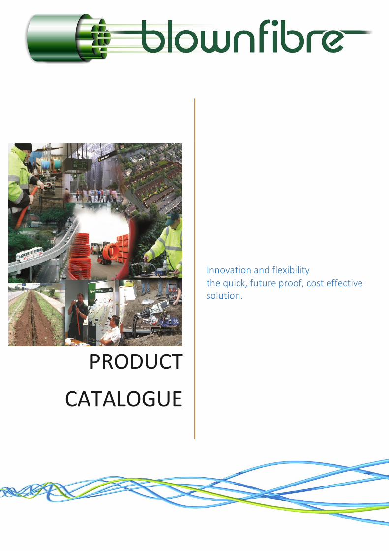
PRODUCT
CATALOGUE
Innovation and flexibility the quick, future proof, cost effective solution.

1 | P a g e
Table of Contents INTRODUCTION ...................................................................................................................................... 2 FIBRE TO THE X – APPLICATIONS ........................................................................................................... 4 FIBRE TO THE HOME ............................................................................................................................... 5 IN-BUILDING ........................................................................................................................................... 6 CAMPUS/BUSINESS PARKS .................................................................................................................... 7 NETWORK OPERATORS .......................................................................................................................... 8 LONG-DISTANCE ..................................................................................................................................... 9 MINING ................................................................................................................................................. 10 INFRASTRUCTURE - PRODUCTS............................................................................................................ 11
RIBBED-PIPE ...................................................................................................................................... 11 SUB-DUCT ......................................................................................................................................... 11 MICRO-DUCT .................................................................................................................................... 12 ACCESS CHAMBERS .......................................................................................................................... 12 BOUNDARY BOX ............................................................................................................................... 12
BLOWN FIBRE – PRODUCTS ................................................................................................................. 14 BLOWN FIBRE – MICRO-DUCT .......................................................................................................... 14
Direct Burial Metal Free – DBmf .................................................................................................. 14 Direct Install – DI .......................................................................................................................... 15 Low Fire Hazard – LFH .................................................................................................................. 15 Polyethylene Flame Retardant – PE FR........................................................................................ 16 Aerial – PE F8 ................................................................................................................................ 16 Special Products ........................................................................................................................... 17
MICRO BLOWN CABLE .......................................................................................................................... 18 FIBRE UNITS/BUNDLES – FU ................................................................................................................. 19 FttH DROP CABLES ................................................................................................................................ 20 OPTICAL FIBRE TERMINATION ............................................................................................................. 21 OPTICAL FIBRE ADAPTERS ................................................................................................................... 22 TUBE BUNDLE CONNECTIVITY – External ............................................................................................ 22 FIBRE CONNECTIVITY ............................................................................................................................ 24 CONNECTORS........................................................................................................................................ 30 INSTALLATION EQUIPMENT ................................................................................................................. 32 TOOLS.................................................................................................................................................... 33 TRAINING .............................................................................................................................................. 34 CONTACT DETAIL .................................................................................................................................. 35
2 | P a g e
INTRODUCTION
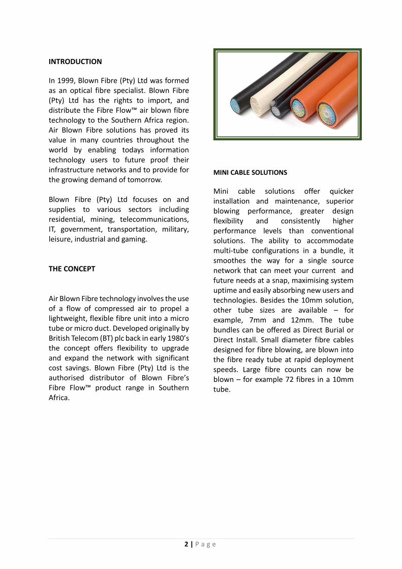
In 1999, Blown Fibre (Pty) Ltd was formed as an optical fibre specialist. Blown Fibre (Pty) Ltd has the rights to import, and distribute the Fibre Flow™ air blown fibre technology to the Southern Africa region. Air Blown Fibre solutions has proved its value in many countries throughout the world by enabling todays information technology users to future proof their infrastructure networks and to provide for the growing demand of tomorrow. Blown Fibre (Pty) Ltd focuses on and supplies to various sectors including residential, mining, telecommunications, IT, government, transportation, military, leisure, industrial and gaming. THE CONCEPT Air Blown Fibre technology involves the use of a flow of compressed air to propel a lightweight, flexible fibre unit into a micro tube or micro duct. Developed originally by British Telecom (BT) plc back in early 1980’s the concept offers flexibility to upgrade and expand the network with significant cost savings. Blown Fibre (Pty) Ltd is the authorised distributor of Blown Fibre’s Fibre Flow™ product range in Southern Africa.
MINI CABLE SOLUTIONS
Mini cable solutions offer quicker installation and maintenance, superior blowing performance, greater design flexibility and consistently higher performance levels than conventional solutions. The ability to accommodate multi-tube configurations in a bundle, it smoothes the way for a single source network that can meet your current and future needs at a snap, maximising system uptime and easily absorbing new users and technologies. Besides the 10mm solution, other tube sizes are available – for example, 7mm and 12mm. The tube bundles can be offered as Direct Burial or Direct Install. Small diameter fibre cables designed for fibre blowing, are blown into the fibre ready tube at rapid deployment speeds. Large fibre counts can now be blown – for example 72 fibres in a 10mm tube.

3 | P a g e
BLOWN FIBRE SOLUTIONS
The desired route is constructed using “Fibre Ready Cable”, a duct resembling a Fibre Optical Cable but which is in fact an empty tube system with tube counts of 1, 2, 4, 7, 12, 19 and 24 tubes respectively. A “Fibre Bundle” comprising of 2, 4, 8 and 12 fibres which is encapsulated in an acrylic coating is then installed into the tube with the aid of Compressed Air through a small installation unit known as the “Blowing Head”. This solution offers customers future proof technology into the network with the advantage of rapid, point to point fibre deployment. Multiple fibre types can be deployed within the same tube infrastructure, deferring capital cost and cost of ownership.
WE OFFER –
PRODUCTS
Optical fibre cables – Micro blown fibre cables & fibre units/bundles
Ducts – Ribbed pipe, sub-duct, micro duct
Access chambers – Modular Optical fibre accessories – Tube
closers, tube connectors, tube management, blown fibre tools & blowing equipment
SERVICES
Tube installation & blowing training courses
Fibre blowing services
Supply product certification and warranties
Design & engineering of blown fibre networks
Onsite support & quality assurance
COMPANY OVERVIEW Blown Fibre is a level 2 B-BBEE – QSE Company. MISSION - Our mission is to future proof South Africa infrastructure today and to provide for the growing demand of tomorrow. VISION - We focus on service delivery in the communication industry by introducing world renowned product solutions to various markets and ensuring the latest proven technology for today’s demands.
4 | P a g e
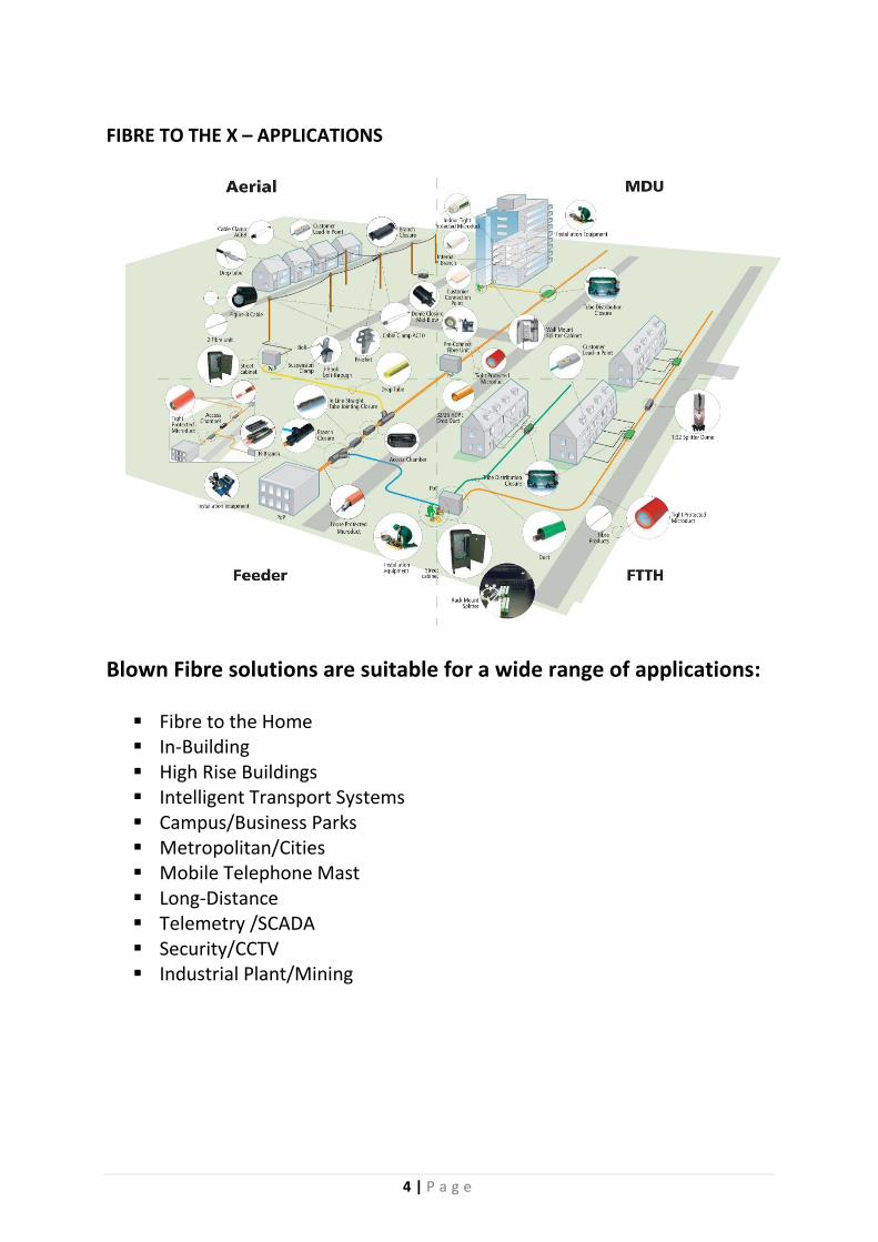
FIBRE TO THE X – APPLICATIONS
Blown Fibre solutions are suitable for a wide range of applications:
Fibre to the Home In-Building High Rise Buildings Intelligent Transport Systems Campus/Business Parks Metropolitan/Cities Mobile Telephone Mast Long-Distance Telemetry /SCADA Security/CCTV Industrial Plant/Mining

5 | P a g e
FIBRE TO THE HOME fibreflow™ in Fibre to The Home applications Imagine a housing development with no running water, no gas, and no electricity – the result: no buyers. You can now add high-speed broadband access to that list of necessities, for it has indeed become the fourth utility. To a great extent, optical fibre initiated and continues to feed users hunger for bandwidth, creating a market that is increasingly demanding high-speed broadband, and is willing to pay for it. Currently, there are many broadband applications that people want, and want today: video-on-demand, high-definition TV, gaming, home security, telecommunications, movie downloads, home education, video-conferencing, sophisticated telephone service and more. A fairly modest mix of these services could involve transference speeds beyond traditional infrastructures. Optical fibre, however, is up to the task, and when deployed with fibreflow™ can be installed easily, efficiently and cost effectively. One of the strengths of it is that with new constructions, tubes can be laid fibre-ready along with other utility lines. This drastically reduces build costs and the higher, often unnecessary, cost of redundant fibre provision. As customer requirements emerge and expand – and they will, because we’re just in the early stages of the broadband explosion – fibre bundles can simply be blown in to supply service where it is required, when it is required. Ethernet-based FttH and PON-based FttH Solutions such as fibreflow™ are increasingly being used in high-speed Passive Optical Networks (PONs) and Ethernet-based Point to Point (P2P). With PONs, a signal is sent down one fibre from a central location and is split with passive optical splitters. With P2P, a direct fibre link connects devices either to each other, a hub or a backbone. When fibre service is provided to multi-office buildings with either of these architectures, capacity is key. With traditional technologies, the answer is to install surplus fibre. This eliminates re-digging and other intrusive work that would have to be done when more capacity is needed. However, it also entails a large start-up investment – one that might never be recouped, simply because the predicted capacity requirements might
never materialise. The result – lots of costly fibre doing nothing. With fibreflow™, you avoid all that. Instead of having to lay extra fibre at the outset, you install only what you need right now. To add capacity in the future, just blow in the fibre. This enables you to minimise your initial investment and to make future investments solely on the basis of increased efficiency (money saved) and new revenue generation.
Customer benefits with fibreflow™ used in Fibre to the Home
Lower costs per additional customer Reduced number of splices between the
Point of Presence (POP) and end user Reduced installation costs Cheaper closures and connectivity
products Reduced maintenance costs Reduced fibre costs in the short and
long term Elimination of unused fibres in new
networks 'Pay-as-you-grow' capabilities Reduced access charges
6 | P a g e
IN-BUILDING
fibreflow™ in in-building applications
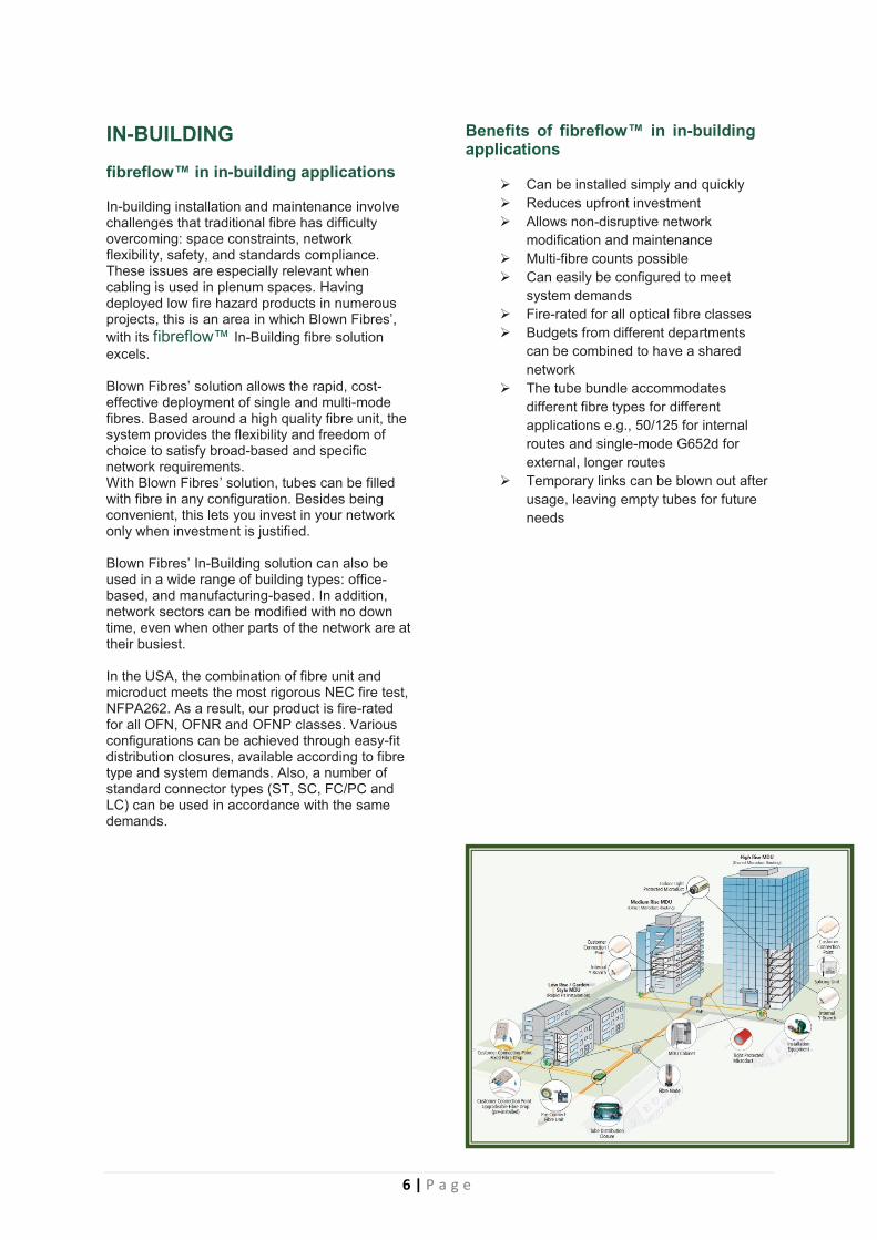
In-building installation and maintenance involve challenges that traditional fibre has difficulty overcoming: space constraints, network flexibility, safety, and standards compliance. These issues are especially relevant when cabling is used in plenum spaces. Having deployed low fire hazard products in numerous projects, this is an area in which Blown Fibres’,
with its fibreflow™ In-Building fibre solution
excels. Blown Fibres’ solution allows the rapid, cost-effective deployment of single and multi-mode fibres. Based around a high quality fibre unit, the system provides the flexibility and freedom of choice to satisfy broad-based and specific network requirements. With Blown Fibres’ solution, tubes can be filled with fibre in any configuration. Besides being convenient, this lets you invest in your network only when investment is justified. Blown Fibres’ In-Building solution can also be used in a wide range of building types: office-based, and manufacturing-based. In addition, network sectors can be modified with no down time, even when other parts of the network are at their busiest. In the USA, the combination of fibre unit and microduct meets the most rigorous NEC fire test, NFPA262. As a result, our product is fire-rated for all OFN, OFNR and OFNP classes. Various configurations can be achieved through easy-fit distribution closures, available according to fibre type and system demands. Also, a number of standard connector types (ST, SC, FC/PC and LC) can be used in accordance with the same demands.
Benefits of fibreflow™ in in-building applications
Can be installed simply and quickly
Reduces upfront investment
Allows non-disruptive network
modification and maintenance
Multi-fibre counts possible
Can easily be configured to meet
system demands
Fire-rated for all optical fibre classes
Budgets from different departments
can be combined to have a shared
network
The tube bundle accommodates
different fibre types for different
applications e.g., 50/125 for internal
routes and single-mode G652d for
external, longer routes
Temporary links can be blown out after
usage, leaving empty tubes for future
needs
7 | P a g e
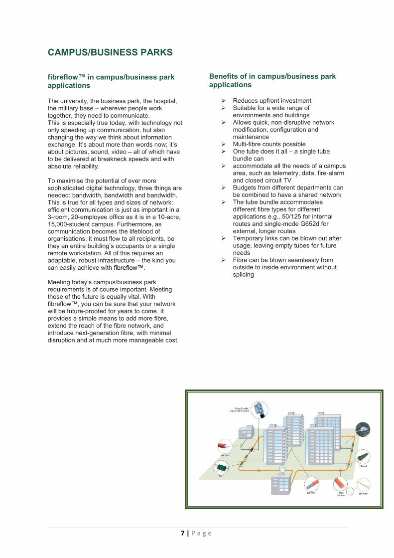
CAMPUS/BUSINESS PARKS
fibreflow™ in campus/business park applications
The university, the business park, the hospital, the military base – wherever people work together, they need to communicate. This is especially true today, with technology not only speeding up communication, but also changing the way we think about information exchange. It’s about more than words now; it’s about pictures, sound, video – all of which have to be delivered at breakneck speeds and with absolute reliability. To maximise the potential of ever more sophisticated digital technology, three things are needed: bandwidth, bandwidth and bandwidth. This is true for all types and sizes of network: efficient communication is just as important in a 3-room, 20-employee office as it is in a 10-acre, 15,000-student campus. Furthermore, as communication becomes the lifeblood of organisations, it must flow to all recipients, be they an entire building’s occupants or a single remote workstation. All of this requires an adaptable, robust infrastructure – the kind you can easily achieve with fibreflow™. Meeting today’s campus/business park requirements is of course important. Meeting those of the future is equally vital. With fibreflow™, you can be sure that your network will be future-proofed for years to come. It provides a simple means to add more fibre, extend the reach of the fibre network, and introduce next-generation fibre, with minimal disruption and at much more manageable cost.
Benefits of in campus/business park applications
Reduces upfront investment Suitable for a wide range of
environments and buildings Allows quick, non-disruptive network
modification, configuration and maintenance
Multi-fibre counts possible One tube does it all – a single tube
bundle can accommodate all the needs of a campus
area, such as telemetry, data, fire-alarm and closed circuit TV
Budgets from different departments can be combined to have a shared network
The tube bundle accommodates different fibre types for different applications e.g., 50/125 for internal routes and single-mode G652d for external, longer routes
Temporary links can be blown out after usage, leaving empty tubes for future needs
Fibre can be blown seamlessly from outside to inside environment without splicing
8 | P a g e
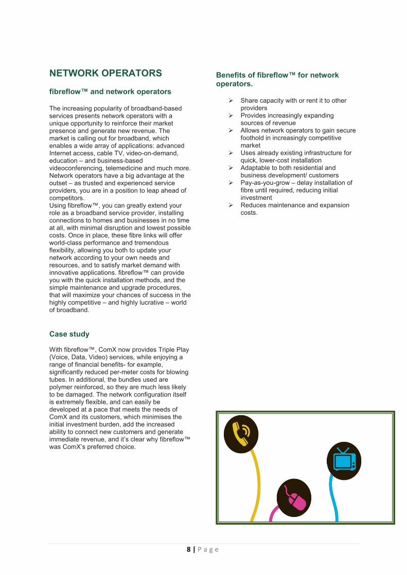
NETWORK OPERATORS fibreflow™ and network operators The increasing popularity of broadband-based services presents network operators with a unique opportunity to reinforce their market presence and generate new revenue. The market is calling out for broadband, which enables a wide array of applications: advanced Internet access, cable TV, video-on-demand, education – and business-based videoconferencing, telemedicine and much more. Network operators have a big advantage at the outset – as trusted and experienced service providers, you are in a position to leap ahead of competitors. Using fibreflow™, you can greatly extend your role as a broadband service provider, installing connections to homes and businesses in no time at all, with minimal disruption and lowest possible costs. Once in place, these fibre links will offer world-class performance and tremendous flexibility, allowing you both to update your network according to your own needs and resources, and to satisfy market demand with innovative applications. fibreflow™ can provide you with the quick installation methods, and the simple maintenance and upgrade procedures, that will maximize your chances of success in the highly competitive – and highly lucrative – world of broadband.
Case study With fibreflow™, ComX now provides Triple Play (Voice, Data, Video) services, while enjoying a range of financial benefits- for example, significantly reduced per-meter costs for blowing tubes. In additional, the bundles used are polymer reinforced, so they are much less likely to be damaged. The network configuration itself is extremely flexible, and can easily be developed at a pace that meets the needs of ComX and its customers, which minimises the initial investment burden, add the increased ability to connect new customers and generate immediate revenue, and it’s clear why fibreflow™ was ComX’s preferred choice.
Benefits of fibreflow™ for network operators.
Share capacity with or rent it to other providers
Provides increasingly expanding sources of revenue
Allows network operators to gain secure foothold in increasingly competitive market
Uses already existing infrastructure for quick, lower-cost installation
Adaptable to both residential and business development/ customers
Pay-as-you-grow – delay installation of fibre until required, reducing initial investment
Reduces maintenance and expansion costs.
9 | P a g e
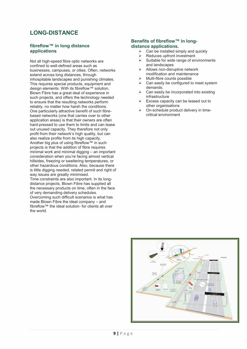
LONG-DISTANCE fibreflow™ in long distance applications Not all high-speed fibre optic networks are confined to well-defined areas such as businesses, campuses, or cities. Often, networks extend across long distances, through inhospitable landscapes and punishing climates. This requires special products, equipment and design elements. With its fibreflow™ solution, Blown Fibre has a great deal of experience in such projects, and offers the technology needed to ensure that the resulting networks perform reliably, no matter how harsh the conditions. One particularly attractive benefit of such fibre-based networks (one that carries over to other application areas) is that their owners are often hard-pressed to use them to limits and can lease out unused capacity. They therefore not only profit from their network’s high quality, but can also realize profits from its high capacity. Another big plus of using fibreflow™ in such projects is that the addition of fibre requires minimal work and minimal digging – an important consideration when you’re facing almost vertical hillsides, freezing or sweltering temperatures, or other hazardous conditions. Also, because there is little digging needed, related permit and right of way issues are greatly minimised. Time constraints are also important. In its long-distance projects, Blown Fibre has supplied all the necessary products on time, often in the face of very demanding delivery schedules. Overcoming such difficult scenarios is what has made Blown Fibre the ideal company – and fibreflow™ the ideal solution- for clients all over the world.
Benefits of fibreflow™ in long-distance applications.
Can be installed simply and quickly Reduces upfront investment Suitable for wide range of environments
and landscapes Allows non-disruptive network
modification and maintenance Multi-fibre counts possible Can easily be configured to meet system
demands. Can easily be incorporated into existing
infrastructure Excess capacity can be leased out to
other organisations On-schedule product delivery in time-
critical environment
10 | P a g e
MINING fibreflow™ in mining applications When it comes to establishing a reliable and high-performance communication system, the mining industry has amongst the most pressing needs and daunting challenges. SPACE, SAFETY, SECURITY & PRODUCTION. These and other important issues have a much higher significance in the mining environment. Fibre optic cabling is the logical solution for mine-based applications because of its high bandwidth capabilities and minimum space requirements. However, traditional implementation techniques require considerable built-in redundancy at the outset, which increases start-up costs. In addition, network maintenance and upgrades can involve severe operational disruption and long down times – not to mention potentially dangerous procedures. A technology that eliminates the need for redundant cabling would definitely offer far-reaching practical and financial advantages. Fibreflow™ offers the flexibility needed for mining environments Blown fibre offers all the benefits of conventional fibre optics, while providing significant additional benefits in terms of security, safety, production capabilities and growth potential. In mining projects, cabling need to be installed in very tight and often hazardous areas, for example, down a vertical shaft. With fibreflow™ technology, such precarious installations can be completed with speed and ease. Future maintenance or upgrades can be performed instantly. By using spare tubes in a route, mining production can continue as usual and ‘live fibres’ remain untouched, no downtime! Fewer people are required to do upgrades or changes thus reducing the security and safety risk. Mines need to be in operation 24 hours, 7 days a week to keep up with demand, so down time has to be kept to a minimum. Fibreflow™ offers flexibility and peace of mind that is so crucial in these environments.
Immediate and long-term financial benefits In financial terms, fibreflow™ outperforms conventional fibre because it eliminates the need for redundancy and reduces start-up costs. For example, installers blow in only the cabling that is required for current requirements. Future requirements? Fibre can be added with ease as and when the need arises. This in addition to the reduction in required personnel and equipment
costs, along with financial losses avoided by continual operation makes it clear that fibreflow™ technology offers considerable financial advantages over the life span of a network.
Cabling designed for the special demands of the mining industry Mining projects require a design that would be durable and offer protection to the people down in the mine. With this in mind, a heavy duty HDPE tube with Corrugated Steel Tape (CST), fully filled with PVC between primary tubes and covered with an outer sheath made of a Low Smoke, Zero Halogen (LSZH) orange coloured compound was created to customer specifications.
Summary Fibre optic cabling, when applied with fibreflow™ blown fibre technology is the ideal choice for the demanding requirements of the mining industry.
Important points to remember when considering using fibreflow’s blown fibre technology:
Security
Fewer personnel needs to be involved
Safety
Procedures are much less hazardous
Production reliability
No down time, no disruption
Growth potential
Bundles can be added and modified in
line with demand
Space
Compact and physically flexible
Capacity
Future proof network
Expenditure
Lower long-term cost of ownership

11 | P a g e
INFRASTRUCTURE - PRODUCTS Blown Fibre offer a large variety of infrastructure products suitable for any infrastructure project. Our products are manufactured with the highest quality virgin material, supplying you with best possible products.
RIBBED-PIPE
Ribbed-Pipe OD
Mass nom g/m Supply Lengths - Sections Supply Lengths - Coils
50mm 25m / 50m
110mm 6m 25m
SUB-DUCT
Sub duct OD/ID
Wall Thick-ness nom
Mass nom g/m
Min Bend rad mm
Coil Lengths
Drum Lengths
32/26 3.0 240 640 1000 1000/2000
32/27 2.5 245 640 1000 1000/2000
40/33 3.5 392 800 1000 1000
40/34 3.0 374 800 1000 1000
50/42 3.7 603 1000 1000 1000
HDPE Pipe HDPE Sub-Duct Micro Duct Modular Chambers
HDPE Sub-Ducts are available in the following sizes, lengths and packaging types. Smooth interior silicone, for optimal floating/blowing performance. - Various colours available
Double wall corrugated construction, manufactured with high impact strength HDPE. Smooth inner for easy cable installation. - Various colours available
12 | P a g e
MICRO-DUCT
Description Microduct Size Bundle OD mm
Supply Lengths Meter
Mass kg/km
Min Bend Radius mm
Max Pull N
1 Way DBmf 12/10mm 15.0 x 15.0 1000 76 300 400
2 Way DBmf 12/10mm 15.2 x 26.8 1000 160 310 600
4 Way DBmf 12/10mm 27.2 x 27.2 1000 288 544 900
7 Way DBmf 12/10mm 39.2 x 39.2 1000 457 784 1200
1 Way DBmf 14/10mm 14.0 x 14.0 1000 69 300 400
2 Way DBmf 14/10mm 17.2 x 31.2 1000 270 345 600
4 Way DBmf 14/10mm 31.2 x 31.2 1000 455 625 900
7 Way DBmf 14/10mm 45.2 x 45.2 1000 715 905 1200
ACCESS CHAMBERS STAKBOX™,
Nominal Size Knock-out Min. Internal frame Max. Eternal Box Dim.
300x300x300mm 2 x 2 way 290x290mm 420x420mm
300x450x300mm 2 x 3 way 270x435mm 410x575mm
450x450x300mm 3 x 3 way 425x425mm 565x565mm
450x600x300mm 3 x 4 way 430x565mm 565x715mm
600x600x300mm 4 x 4 way 565x565mm 715x715mm
BOUNDARY BOX Square boundary box or “Toby Box”, which is small and compact. This chamber/boundary box is ideal for FttHome connections. Size – 130mm x 140mm x 75mm
Stakbox™, a pre- fabricated, stackable, access chamber system. The boxes are quick and easy to install requiring no specialised skills. They are manufactured from polyethylene which is extremely robust, will not corrode, and is chemically resistant, to most chemicals. - Lids available in galvanized steel or polymer concrete.
HDPE Microduct assemblies offer multi duct flexibility, and future proofing all in the same assembly. Suitable for direct burial, and available in different tube counts. - Various colours available
13 | P a g e
Rhi-Node RHI-NODE 300
Daylight Opening Depth Coping Size Duct Configuration
200m
300mm
285 x 285mm
4 x 20mm Knock-out
4 x 25mm Knock-out 2 x 50mm Knock-out
Weight 5kg
Load Rating SANS 558 Light Duty (7kN)
RHI-NODE 600
Daylight Opening Depth Coping Size Duct Configuration
350m
600mm
600mm
8 x 50mm Split Entry
12 x 110mm Knock-out
Weight 46kg
Load Rating SANS 558 Medium Duty (40kN)
RHI-NODE 1000
Daylight Opening Depth Coping Size Duct Configuration
650m
600mm
600mm
4 x 20mm Knock-out
4 x 25mm Knock-out 2 x 50mm Knock-out
Weight 5kg
Load Rating SANS 558 Light Duty (7kN)
Rhi-Node access chambers offer unique duct and pipe entry/exit ports with the option of Smart Locking Logic lids. These access chambers are manufactured with SMC (sheet moulded compound) that reduces weight and still offers high strength. SMC materials are also UV resistant.
14 | P a g e
BLOWN FIBRE – PRODUCTS
BLOWN FIBRE – MICRO-DUCT Micro ducts can be bundled as 1-way to 24-way configurations with micro duct diameter ranging from 3mm to 16mm. Bundles are available in several types – for example, Direct Burial – DB Low Fire Hazard – LFH Direct Install – DI Flame Retardant – PE FR
- Making them ideal for diverse applications such as FttH, Campus, In-Building, Campus and even harsh environments such as mines and industrial plants.
Direct Burial Metal Free – DBmf
Suitable for direct burial applications and where by power cable may share the trench.
Type Description Tube
OD mm Tube ID mm
Bundle OD mm
Mass g/m
Min Bend Radi mm
Max Pull N
1DBmf 1 Way Direct Burial Metal Free 5 3.5 10.0 61 150 200
2DBmf 2 Way Direct Burial Metal Free 5 3.5 12.3 x 17.3
145 185 800
4DBmf 4 Way Direct Burial Metal Free 5 3.5 19.4 203 300 1100
7DBmf 7 Way Direct Burial Metal Free 5 3.5 22.3 261 335 1450
12DBmf 12 Way Direct Burial Metal Free 5 3.5 28.3 389 425 2150
19DBmf 19 Way Direct Burial Metal Free 5 3.5 32.3 499 550 2750
24DBmf 24 Way Direct Burial Metal Free 5 3.5 37.9 636 645 3500
1DBmf 1 Way Direct Burial Metal Free 8 5 8.0 30 160 200
2DBmf 2 Way Direct Burial Metal Free 8 5 9.5 x 17.5
75 220 500
4DBmf 4 Way Direct Burial Metal Free 8 5 19.7 121 325 950
7DBmf 7 Way Direct Burial Metal Free 8 5 26.0 280 520 1500
12DBmf 12 Way Direct Burial Metal Free 8 5 33.2 405 430 1800
Assemblies of PE microducts (m/d) (5mm), each with low friction performance. Each assembly (tube bundle) is surrounded by a metal-free water activated tape. Over this is a flexible black sheath of PE, then an outer layer of rugged orange coloured PE. These strong and flexible products are designed for direct burial into suitably prepared ground.
Micro Duct Fibre Units Accessories Tools

15 | P a g e
Direct Install – DI
Suitable for in-building installations, or in ribbed pipe or cable trays.
Type Description Tube
OD mm Tube ID mm
Bundle OD mm
Mass g/m
Min Bend Radi mm
Max Pull N
1DI 1 Way Direct Install 5 3.5 8.4 49 120 400
2DI 2 Way Direct Install 5 3.5 8.4 /13.4
77 120 600
4DI 4 Way Direct Install 5 3.5 15.5 118 200 700
7DI 7 Way Direct Install 5 3.5 18.4 162 240 1500
12DI 12 Way Direct Install 5 3.5 23.8 240 310 1600
19DI 19 Way Direct Install 5 3.5 27.8 329 360 2500
24DI 24 Way Direct Install 5 3.5 33.4 437 500 4000
Assemblies of PE microducts (m/d) (5mm), each with low friction performance. Each assembly (tube bundle) is surrounded with a 125um aluminium layer. Over this is a flexible black PE sheath. These strong and flexible products are designed for on rack or in pipe installations and are UV resistant.
Low Fire Hazard – LFH
Meeting IEC 60332-3 and 60332-1 for indoor fire regulations
Type Description Tube
OD mm Tube ID mm
Bundle OD mm
Mass g/m
Min Bend Radi mm
Max Pull N
1LFH 1 Way Low Fire Hazard 5 3.5 7.2 48 100 150
2LFH 2 Way Low Fire Hazard 5 3.5 7.2/12.2 80 150 250
4LFH 4 Way Low Fire Hazard 5 3.5 14.3 126 150 400
7LFH 7 Way Low Fire Hazard 5 3.5 17.2 190 220 600
12LFH 12 Way Low Fire Hazard 5 3.5 22.9 310 300 950
19LFH 19 Way Low Fire Hazard 5 3.5 26.9 438 350 1300
24LFH 24 Way Low Fire Hazard 5 3.5 32.5 591 500 1800
Assemblies of PE microducts (m/d) (5mm), each with low friction performance. Each assembly (tube bundle) is surrounded with a sheath of LFH material suitable for indoor fire regulation use. * Low flammability * Halogen free * Low Smoke
16 | P a g e
Polyethylene Flame Retardant – PE FR
Suitable for industrial and mining applications with regards to hazardous working areas
Type Description Tube
OD mm Tube ID mm
Bundle OD mm
Mass g/m
Min Bend Radi mm
Supply Lengths
1PEFR 1 Way PE Flame Retardant 5 3.5 11 73 165 4000m
2PEFR 2 Way PE Flame Retardant 5 3.5 13.4x 19
174 210 4000m
4PEFR 4 Way PE Flame Retardant 5 3.5 20.9 243 320 4000m
7PEFR 7 Way PE Flame Retardant 5 3.5 24.4 305 350 4000m
12PEFR 12 Way PE Flame Retardant 5 3.5 31.1 466 460 3000m
19PEFR 19 Way PE Flame Retardant 5 3.5 35.2 599 530 2000m
24PEFR 24 Way PE Flame Retardant 5 3.5 41.7 764 620 2000m
Assemblies of PE microducts (m/d) (5mm), each with low friction performance. Each assembly (tube bundle) is surrounded with a double sheath of polyethylene flame retardant material suitable for indoor or outdoor fire regulation use. The polyethylene flame retardant material is halogen free and is UV stabilized.
Aerial – PE F8
Suitable for overhead applications – with span lengths up to 90 meters.
Type Description Tube
OD mm Tube ID mm
Mass g/m
Total Weight
Strength Member
Supply Length
1PEF8 Drop 5 3.5 42 52Kg Steel 1000m
4PEF8 4 Way PE Figure 8 5 3.5 313 1597kg Steel 4000m
7PEF8 7 Way PE Figure 8 5 3.5 367 2038kg Steel 4000m
12PEF8 12 Way PE Figure 8 5 3.5 453 1251kg Steel 2000m
19PEF8 19 Way PE Figure 8 5 3.5 549 1668kg Steel 2000m
4PEF8 4 Way PE Figure 8 12 10 401 638kg Steel 1000m
7PEF8 7 Way PE Figure 8 12 10 676 1021kg Steel 1000m
Assemblies of PE microducts (m/d) (5mm), each with low friction performance. Each assembly (tube bundle) is surrounded with a double sheath of polyethylene UV stabilized material suitable for outdoor aerial use. The assembly has a 6mm catenary wire attached for aerial support.
17 | P a g e
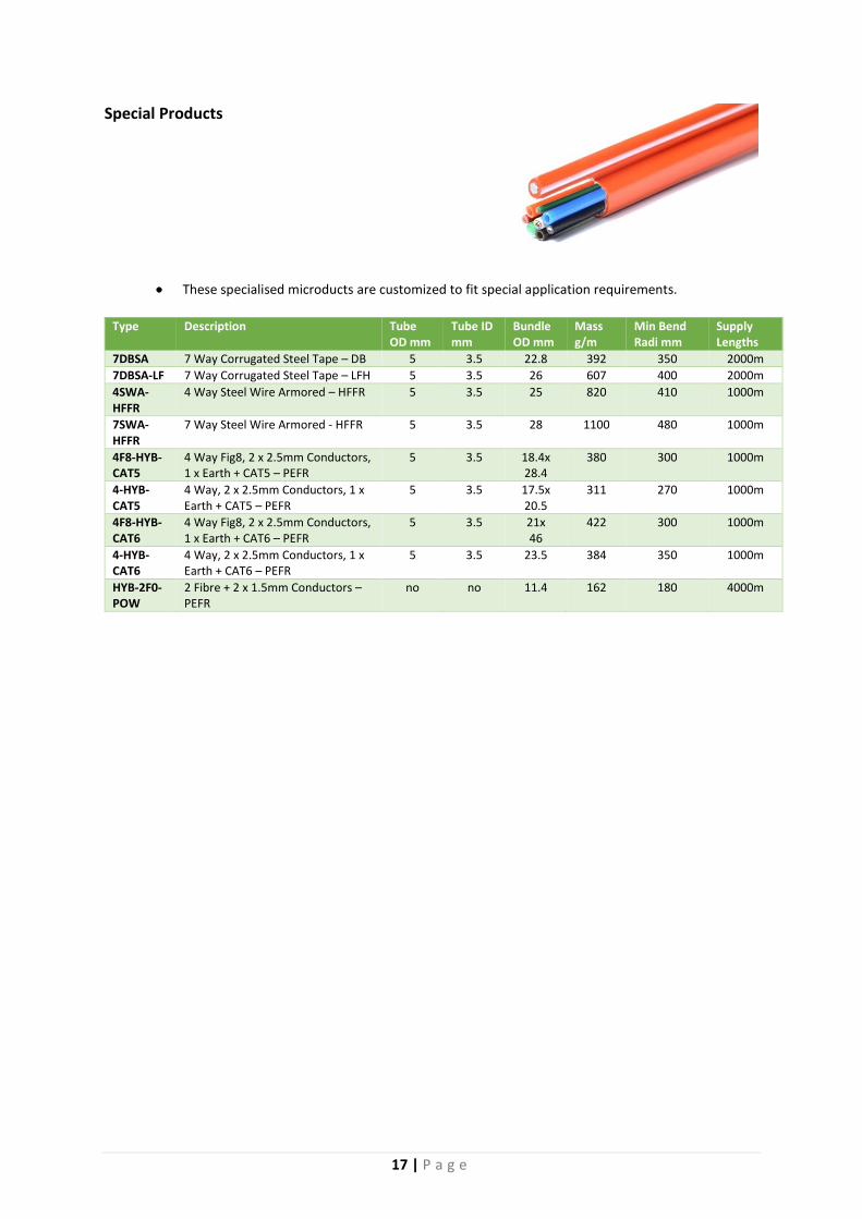
Special Products
These specialised microducts are customized to fit special application requirements.
Type Description Tube
OD mm Tube ID mm
Bundle OD mm
Mass g/m
Min Bend Radi mm
Supply Lengths
7DBSA 7 Way Corrugated Steel Tape – DB 5 3.5 22.8 392 350 2000m
7DBSA-LF 7 Way Corrugated Steel Tape – LFH 5 3.5 26 607 400 2000m
4SWA-HFFR
4 Way Steel Wire Armored – HFFR 5 3.5 25 820 410 1000m
7SWA-HFFR
7 Way Steel Wire Armored - HFFR 5 3.5 28 1100 480 1000m
4F8-HYB-CAT5
4 Way Fig8, 2 x 2.5mm Conductors, 1 x Earth + CAT5 – PEFR
5 3.5 18.4x 28.4
380 300 1000m
4-HYB-CAT5
4 Way, 2 x 2.5mm Conductors, 1 x Earth + CAT5 – PEFR
5 3.5 17.5x 20.5
311 270 1000m
4F8-HYB-CAT6
4 Way Fig8, 2 x 2.5mm Conductors, 1 x Earth + CAT6 – PEFR
5 3.5 21x 46
422 300 1000m
4-HYB-CAT6
4 Way, 2 x 2.5mm Conductors, 1 x Earth + CAT6 – PEFR
5 3.5 23.5 384 350 1000m
HYB-2F0-POW
2 Fibre + 2 x 1.5mm Conductors – PEFR
no no 11.4 162 180 4000m

18 | P a g e
MICRO BLOWN CABLE
Suitable for blowing into micro duct of 12/10, 14/10 or 16/13mm
Type Description Fibre Count Cable
OD mm Microduct Size mm
Blowing Distance
Drum Lengths
Multimode 50/125 OM1/OM2/OM3
Micro blown fibre cable – MM
12, 24, 48, 72 5.8 12/10 14/10 16/12
2000m 4000m
Multimode 50/125 OM1/OM2/OM3
Micro blown fibre cable – MM
96 7.3 12/10 14/10 16/12
1000m 4000m
Multimode 50/125 OM1/OM2/OM3
Micro blown fibre cable – MM
144 7.9 12/10 14/10 16/12
1000m 4000m
Single Mode 9/125 G652d/G655/ G657A1
Micro blown fibre cable – SM
12, 24, 48, 72 5.8 12/10 14/10 16/12
2000m 4000m
Single Mode 9/125 G652d/G655/ G657A1
Micro blown fibre cable – SM
96 7.3 12/10 14/10 16/12
1000m 4000m
Single Mode 9/125 G652d/G655/ G657A1
Micro blown fibre cable – SM
144 7.9 12/10 14/10 16/12
1000m 4000m
Technical Data
Distribution Loose tube containing 12 fibres (typical)
Stranding SZ
Central Strength Member FRP
Minimum Bend Radius During Installation – 20 x OD / During operation – 15 x OD
Temperatures (Typical) Operating -20ºC to +60ºC
Fibre Identification
No. 1 2 3 4 5 6 7 8 9 10 11 12
Color
EIA 598
19 | P a g e
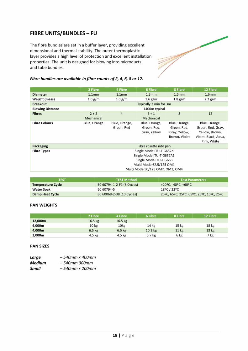
FIBRE UNITS/BUNDLES – FU The fibre bundles are set in a buffer layer, providing excellent dimensional and thermal stability. The outer thermoplastic layer provides a high level of protection and excellent installation properties. The unit is designed for blowing into microducts and tube bundles. Fibre bundles are available in fibre counts of 2, 4, 6, 8 or 12.
2 Fibre 4 Fibre 6 Fibre 8 Fibre 12 Fibre
Diameter 1.1mm 1.1mm 1.3mm 1.5mm 1.6mm
Weight (mass) 1.0 g/m 1.0 g/m 1.6 g/m 1.8 g/m 2.2 g/m
Breakout Typically 2 min for 3m
Blowing Distance 1400m typical
Fibres 2 + 2 Mechanical
4 6 + 1 Mechanical
8 12
Fibre Colours Blue, Orange Blue, Orange, Green, Red
Blue, Orange, Green, Red, Gray, Yellow
Blue, Orange, Green, Red,
Gray, Yellow, Brown, Violet
Blue, Orange, Green, Red, Gray,
Yellow, Brown, Violet, Black, Aqua,
Pink, White
Packaging Fibre rosette into pan
Fibre Types Single Mode ITU-T G652d Single Mode ITU-T G657A1
Single Mode ITU-T G655 Multi Mode 62.5/125 OM1
Multi Mode 50/125 OM2. OM3, OM4
TEST TEST Method Test Parameters
Temperature Cycle IEC 60794-1-2-F1 (3 Cycles) +20ºC, -40ºC, +60ºC
Water Soak IEC 60794-5 18ºC / 22ºC
Damp Heat Cycle IEC 60068-2-38 (10 Cycles) 25ºC, 65ºC, 25ºC, 65ºC, 25ºC, 10ºC, 25ºC
PAN WEIGHTS
2 Fibre 4 Fibre 6 Fibre 8 Fibre 12 Fibre
12,000m 16.5 kg 16.5 kg
6,000m 10 kg 10kg 14 kg 15 kg 18 kg
4,000m 6.5 kg 6.5 kg 10.2 kg 11 kg 13 kg
2,000m 4.5 kg 4.5 kg 5.7 kg 6 kg 7 kg
PAN SIZES Large – 540mm x 400mm Medium – 540mm 300mm Small – 540mm x 200mm

20 | P a g e
FttH DROP CABLES Blown in or suspended Uni-Tube, (G657A2) Single mode. This can be blown into duct or strung but not hauled. Fibre is available in fibre counts of 2, 4, 6, 8 or 12. Available in Black or White outer sheath.
Technical Information Type Description FO Count Strung and Blowing Distance
G657A2 Fibre Bundle Single mode G657/A2 2, 4, 6, 8 & 12 50m Strung 1000m Blowing
COMMON DATA (all fibre counts): Allowable Tension during Installation: 500N Allowable Tension after Installation: 125N Bend Radius: 10 x Cable Diameter Crush Resistance: 1 000N Temperatures: Storage: -10°C to +70°C Installation: -5°C to +50°C Lifetime: -20°C to +50°C
Fibre colour sequence:
No. 1 2 3 4 5 6 7 8 9 10 11 12
Color
The “Blown-In” Uni-Tube cable is designed for blown duct or strung applications. The cable's non-metallic construction makes it immune to lightning. Excellent optical reliability is ensured by the gel filling in the tube which provides protection against vibration. PLP to be consulted for accessories for this type of cable
21 | P a g e
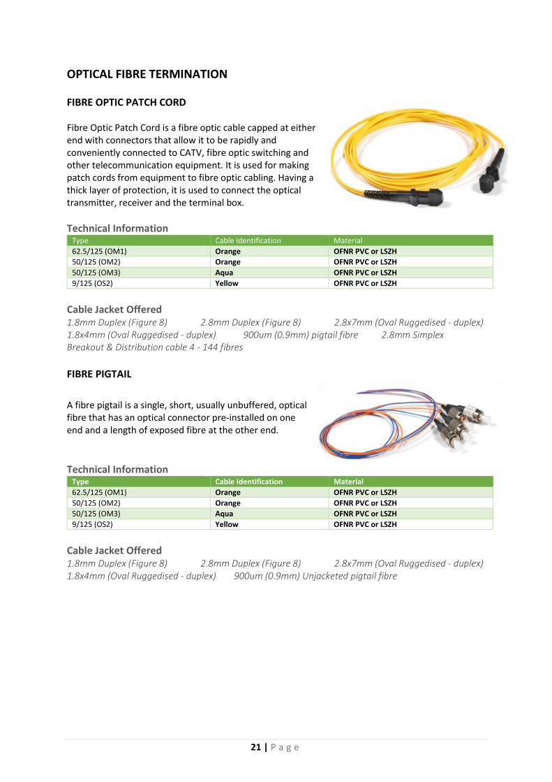
OPTICAL FIBRE TERMINATION FIBRE OPTIC PATCH CORD Fibre Optic Patch Cord is a fibre optic cable capped at either end with connectors that allow it to be rapidly and conveniently connected to CATV, fibre optic switching and other telecommunication equipment. It is used for making patch cords from equipment to fibre optic cabling. Having a thick layer of protection, it is used to connect the optical transmitter, receiver and the terminal box.
Technical Information Type Cable Identification Material
62.5/125 (OM1) Orange OFNR PVC or LSZH
50/125 (OM2) Orange OFNR PVC or LSZH
50/125 (OM3) Aqua OFNR PVC or LSZH
9/125 (OS2) Yellow OFNR PVC or LSZH
Cable Jacket Offered 1.8mm Duplex (Figure 8) 2.8mm Duplex (Figure 8) 2.8x7mm (Oval Ruggedised - duplex) 1.8x4mm (Oval Ruggedised - duplex) 900um (0.9mm) pigtail fibre 2.8mm Simplex Breakout & Distribution cable 4 - 144 fibres
FIBRE PIGTAIL
A fibre pigtail is a single, short, usually unbuffered, optical fibre that has an optical connector pre-installed on one end and a length of exposed fibre at the other end.
Technical Information
Type Cable Identification Material
62.5/125 (OM1) Orange OFNR PVC or LSZH
50/125 (OM2) Orange OFNR PVC or LSZH
50/125 (OM3) Aqua OFNR PVC or LSZH
9/125 (OS2) Yellow OFNR PVC or LSZH
Cable Jacket Offered 1.8mm Duplex (Figure 8) 2.8mm Duplex (Figure 8) 2.8x7mm (Oval Ruggedised - duplex) 1.8x4mm (Oval Ruggedised - duplex) 900um (0.9mm) Unjacketed pigtail fibre
22 | P a g e
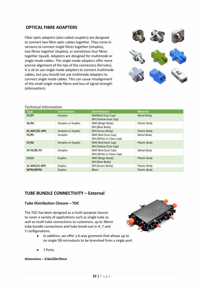
OPTICAL FIBRE ADAPTERS Fiber optic adapters (also called couplers) are designed to connect two fibre optic cables together. They come in versions to connect single fibres together (simplex), two fibres together (duplex), or sometimes four fibres together (quad). Adapters are designed for multimode or single mode cables. The single mode adapters offer more precise alignment of the tips of the connectors (ferrules). It is ok to use single mode adapters to connect multimode cables, but you should not use multimode adapters to connect single mode cables. This can cause misalignment of the small single mode fibres and loss of signal strength (attenuation).
Technical Information Type Construction Identification Material
ST/ST Simplex MM(Red Dust Cap) SM (Yellow Dust Cap)
Metal Body
SC/SC Simplex or Duplex MM (Beige Body) SM (Blue Body)
Plastic Body
SC-APC/SC-APC Simplex or Duplex SM (Green Body) Plastic Body
FC/FC Simplex MM (Red Dust Cap) SM (White or Clear Cap)
Metal Body
ST/SC Simplex or Duplex MM (Red Dust Cap) SM (Yellow Duct Cap)
Plastic Body
ST-FC/SC-FC Simplex MM (Red Dust Cap) SM (White or Clear Cap)
Metal Body
LC/LC Duplex MM (Beige Body) SM (Blue Body)
Plastic Body
LC-APC/LC-APC Duplex SM (Green Body) Plastic Body
MTRJ/MTRJ Duplex Black Plastic Body
TUBE BUNDLE CONNECTIVITY – External
Tube Distribution Closure – TDC The TDC has been designed as a multi-purpose closure to cover a variety of applications such as single tube as well as multi-tube connections to customers, up to 38mm tube bundle connections and tube break-out in H, T and Y configurations.
In addition, we offer a 6-way grommet that allows up to six single DB microducts to be branched from a single port.
7 Ports Dimensions – 316x220x70mm
23 | P a g e
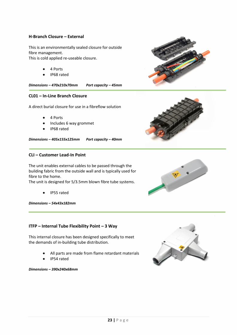
H-Branch Closure – External This is an environmentally sealed closure for outside fibre management. This is cold applied re-useable closure.
4 Ports
IP68 rated Dimensions – 470x210x70mm Port capacity – 45mm
CL01 – In-Line Branch Closure A direct burial closure for use in a fibreflow solution
4 Ports
Includes 6 way grommet
IP68 rated Dimensions – 405x155x125mm Port capacity – 40mm
CLI – Customer Lead-In Point The unit enables external cables to be passed through the building fabric from the outside wall and is typically used for fibre to the home. The unit is designed for 5/3.5mm blown fibre tube systems.
IP55 rated Dimensions – 54x43x182mm
ITFP – Internal Tube Flexibility Point – 3 Way This internal closure has been designed specifically to meet the demands of in-building tube distribution.
All parts are made from flame retardant materials
IP54 rated Dimensions – 390x240x68mm

24 | P a g e
FIBRE CONNECTIVITY
CCP – Customer Connection Point The customer connection point is a compact, multi-functional wall mounted closure, that forms the final part of the fibre-to-the-home solution. The CCP can accept microduct between 3mm and 8mm in diameter. The fibre outlets are either two SC or two duplex LC connectors.
IP54 rated Dimensions – 180x100x20mm
EN-FTX-024 – FttX Optical Fibre Distribution Box External wall-mount optical fibre distribution box offering flexible patch, splice and splitter solutions for FttX networks. Designed for pole or wall mounting.
2 x Cable entry
24 x Simplex cable exit
48 x Fusion splices
24 x SC or 24 x LC duplex adaptors
IP 55 Dimensions – 330x225x90mm
EN-FTX-012 – FttX Optical Fibre Distribution Box External wall-mount optical fibre distribution box offering flexible patch, splice and splitter solutions for FttX networks. Designed for pole or wall mounting.
1 x Cable entry
12 x Simplex cable exit
24 x Fusion splices
12 x SC or 12 x LC duplex adaptors
IP 55 Dimensions – 230x206x64
25 | P a g e
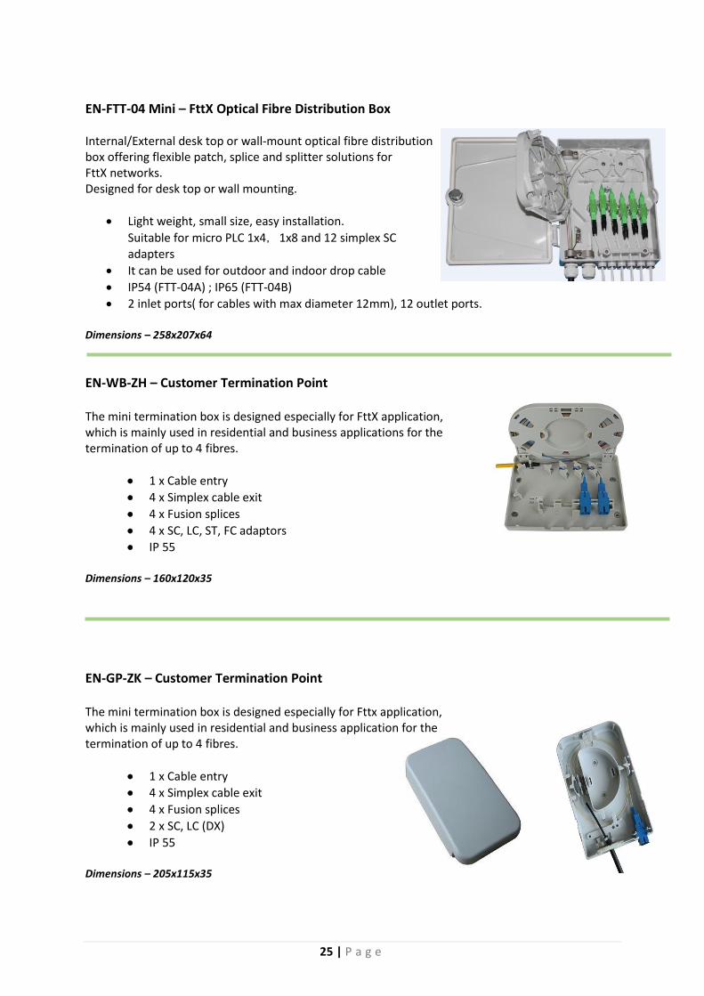
EN-FTT-04 Mini – FttX Optical Fibre Distribution Box Internal/External desk top or wall-mount optical fibre distribution box offering flexible patch, splice and splitter solutions for FttX networks. Designed for desk top or wall mounting.
Light weight, small size, easy installation.
Suitable for micro PLC 1x4,1x8 and 12 simplex SC adapters
It can be used for outdoor and indoor drop cable
IP54 (FTT-04A) ; IP65 (FTT-04B)
2 inlet ports( for cables with max diameter 12mm), 12 outlet ports. Dimensions – 258x207x64
EN-WB-ZH – Customer Termination Point The mini termination box is designed especially for FttX application, which is mainly used in residential and business applications for the termination of up to 4 fibres.
1 x Cable entry
4 x Simplex cable exit
4 x Fusion splices
4 x SC, LC, ST, FC adaptors
IP 55 Dimensions – 160x120x35
EN-GP-ZK – Customer Termination Point The mini termination box is designed especially for Fttx application, which is mainly used in residential and business application for the termination of up to 4 fibres.
1 x Cable entry
4 x Simplex cable exit
4 x Fusion splices
2 x SC, LC (DX)
IP 55 Dimensions – 205x115x35

26 | P a g e
EN-GP-ZR – 4 way Splitter Termination Box The splitter termination box is designed especially for Fttx application, which is mainly used in residential and business application for the termination of up to 4 fibres.
Suitable for micro PLC 1x4 and 4 SC simplex adapters
It can be used for outdoor and indoor drop cable
IP55
1 inlet port, 4 outlet ports.
Dimensions – 210x140x40mm
EN-JFK-02VNH The out-door flat fibre splice closure offers, high durability, waterproofing, fire resistance and is quakeproof. It is suitable for aerial, underground, wall-mount or chamber applications.
1-4 pieces of FOST 3706B Splice trays
Straight-through and branching applications
IP67
8 x LC or SC Midcouplers
2 x 20mm, 2 x 16mm, 2 x 13mm Ports
Dimensions – 323x202x86mm
PPF-4820 & PPF-9620 – Pivoting Termination Panel Rack Mounting Enclosure is designed for standard 19” rack. It has integrative construction of cable fixing, splice protection, distribution and storage of spare fibres. It can complete optical fibre distribution function independently and widely used in comprehensive distribution cabinet, network cabinet and open cabinet
19” standard rack design with static-spray, nice looking;
Suitable for ribbon and bunchy optic fibre;
Suitable for FC, SC, duplex LC adapter;
Clear fibre route, pigtails could be wound and stored within the tray.
Flexible installation, convenient for operation and maintenance
Dimensions – 1U - 19” Rack Mount 2U – 19” Rack Mount
27 | P a g e
EN-SC-4D – Outdoor Fibre Optical Distribution Box
Standard case body, made of high intensity, anti-corrosive, anti-aging special composite material, adapting to various bad weather conditions with reliable sealing, water-proof and damp-proof. Splicing & distribution integration module with adaptor assembling, fusion and connection, storage in integration, inserted assembling and available for different type of adaptors such as FC, SC, ST. Adaptors assembling with defluxion of 30º to ensure fibre pigtail bending radius with perfect control winding ring of the fibre in horizontal and vertical. It make the fibre distribution tidiness and be protected in security. The bottom end is assembled with spare splice tray, for the direct fusion and connection of trunk optical cables and distribution cables. Every side of the cabinet can bear the vertical pressure of 980N, and 200N for the outer edge over the door when door opened.
Model Size (mm) HxWxD
Max Capacity (fibres)
Type of PLC (box type)
No. of adaptors FC, SC, ST, LC (Dx)
EN-SC-4D I 485x385x135 (without base)
48 fibre 1 x 32 (1 pcs) & 1x 16 (1 pcs)
48 pcs
EN-SC-4D II 684x385x135 (with base)
96 or 144 fibre 1 x 32 (2 pcs) 96 pcs
ONT-116 Splice & Distribution Case (SDC) Consisting of SDM, the capacity of SDC is customized designed.
Modular design, combining splicing and distribution into one module.
Adopting page-structure.
FC, SC and ST adaptors are available.
Suitable for ribbon and bunchy optical fibres. Dimensions – 48 Port – 115x335x200 72 Port – 176x430x250
28 | P a g e
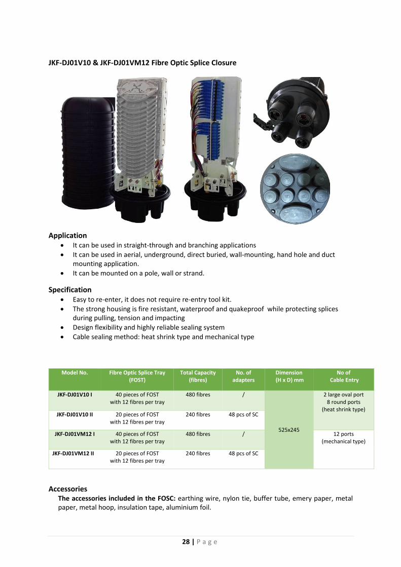
JKF-DJ01V10 & JKF-DJ01VM12 Fibre Optic Splice Closure
Application It can be used in straight-through and branching applications
It can be used in aerial, underground, direct buried, wall-mounting, hand hole and duct mounting application.
It can be mounted on a pole, wall or strand.
Specification Easy to re-enter, it does not require re-entry tool kit.
The strong housing is fire resistant, waterproof and quakeproof while protecting splices during pulling, tension and impacting
Design flexibility and highly reliable sealing system
Cable sealing method: heat shrink type and mechanical type
Model No. Fibre Optic Splice Tray (FOST)
Total Capacity (fibres)
No. of adapters
Dimension (H x D) mm
No of Cable Entry
JKF-DJ01V10 I 40 pieces of FOST with 12 fibres per tray
480 fibres /
525x245
2 large oval port 8 round ports
(heat shrink type) JKF-DJ01V10 II 20 pieces of FOST
with 12 fibres per tray 240 fibres 48 pcs of SC
JKF-DJ01VM12 I 40 pieces of FOST with 12 fibres per tray
480 fibres / 12 ports (mechanical type)
JKF-DJ01VM12 II 20 pieces of FOST with 12 fibres per tray
240 fibres 48 pcs of SC
Accessories The accessories included in the FOSC: earthing wire, nylon tie, buffer tube, emery paper, metal paper, metal hoop, insulation tape, aluminium foil.
29 | P a g e
The accessories to be ordered in addition: earthing ground, pressure testing valve, small heat shrinkable fixing sleeve (for small round) and big heat shrinkable fixing sleeve with branching-off clip (for large oval port)
JKF-FIST-GC02-BC16/BC6 FIST generic closure organizer
FIST is a Fibre Infrastructure System Technology. The generic closure FIST-GCO2 is an environmentally sealed enclosure for the fibre management system that provides the functions of splice and passive component integration in the external network.
The Model of FIST-GCO2BC16/BC6 has the following functions and features Single-ended design
Base and dome are sealed with a clamp and O-ring system
16 round entry/exit ports for drop cables and 1 oval port for looped cable
The UMS (universal mounting system) profiles provide the foundation for mounting combinations of SOSA2(splice only sub-assembly) and/or SASA2(splitter array sub-assembly) modules, which consist of a modular groove plate and trays
Tray Model: SE (thicker tray): Max.12 fibre per tray
30 | P a g e
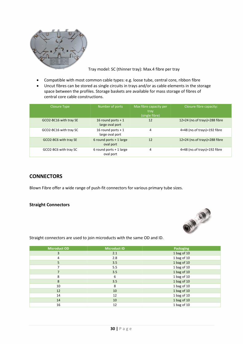
Tray model: SC (thinner tray): Max.4 fibre per tray
Compatible with most common cable types: e.g. loose tube, central core, ribbon fibre
Uncut fibres can be stored as single circuits in trays and/or as cable elements in the storage space between the profiles. Storage baskets are available for mass storage of fibres of central core cable constructions.
Closure Type Number of ports Max fibre capacity per tray
(single fibre)
Closure fibre capacity:
GCO2-BC16 with tray SE 16 round ports + 1 large oval port
12 12×24 (no.of trays)=288 fibre
GCO2-BC16 with tray SC 16 round ports + 1 large oval port
4 4×48 (no.of trays)=192 fibre
GCO2-BC6 with tray SE 6 round ports + 1 large oval port
12 12×24 (no.of trays)=288 fibre
GCO2-BC6 with tray SC 6 round ports + 1 large oval port
4 4×48 (no.of trays)=192 fibre
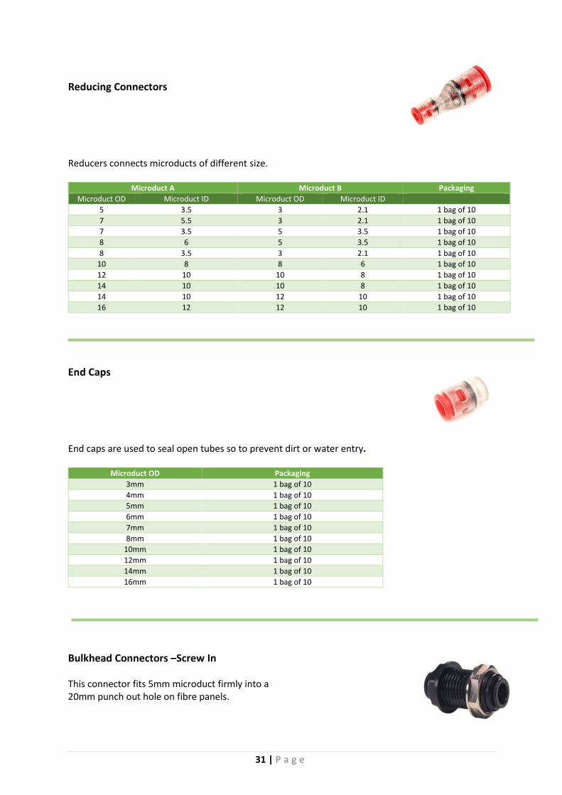
CONNECTORS Blown Fibre offer a wide range of push-fit connectors for various primary tube sizes.
Straight Connectors Straight connectors are used to join microducts with the same OD and ID.
Microduct OD Microduct ID Packaging
3 2.1 1 bag of 10
4 2.8 1 bag of 10
5 3.5 1 bag of 10
7 5.5 1 bag of 10
7 3.5 1 bag of 10
8 6 1 bag of 10
8 3.5 1 bag of 10
10 8 1 bag of 10
12 10 1 bag of 10
14 12 1 bag of 10
14 10 1 bag of 10
16 12 1 bag of 10
31 | P a g e
Reducing Connectors Reducers connects microducts of different size.
Microduct A Microduct B Packaging
Microduct OD Microduct ID Microduct OD Microduct ID
5 3.5 3 2.1 1 bag of 10
7 5.5 3 2.1 1 bag of 10
7 3.5 5 3.5 1 bag of 10
8 6 5 3.5 1 bag of 10
8 3.5 3 2.1 1 bag of 10
10 8 8 6 1 bag of 10
12 10 10 8 1 bag of 10
14 10 10 8 1 bag of 10
14 10 12 10 1 bag of 10
16 12 12 10 1 bag of 10
End Caps End caps are used to seal open tubes so to prevent dirt or water entry.
Microduct OD Packaging
3mm 1 bag of 10
4mm 1 bag of 10
5mm 1 bag of 10
6mm 1 bag of 10
7mm 1 bag of 10
8mm 1 bag of 10
10mm 1 bag of 10
12mm 1 bag of 10
14mm 1 bag of 10
16mm 1 bag of 10
Bulkhead Connectors –Screw In This connector fits 5mm microduct firmly into a 20mm punch out hole on fibre panels.
32 | P a g e
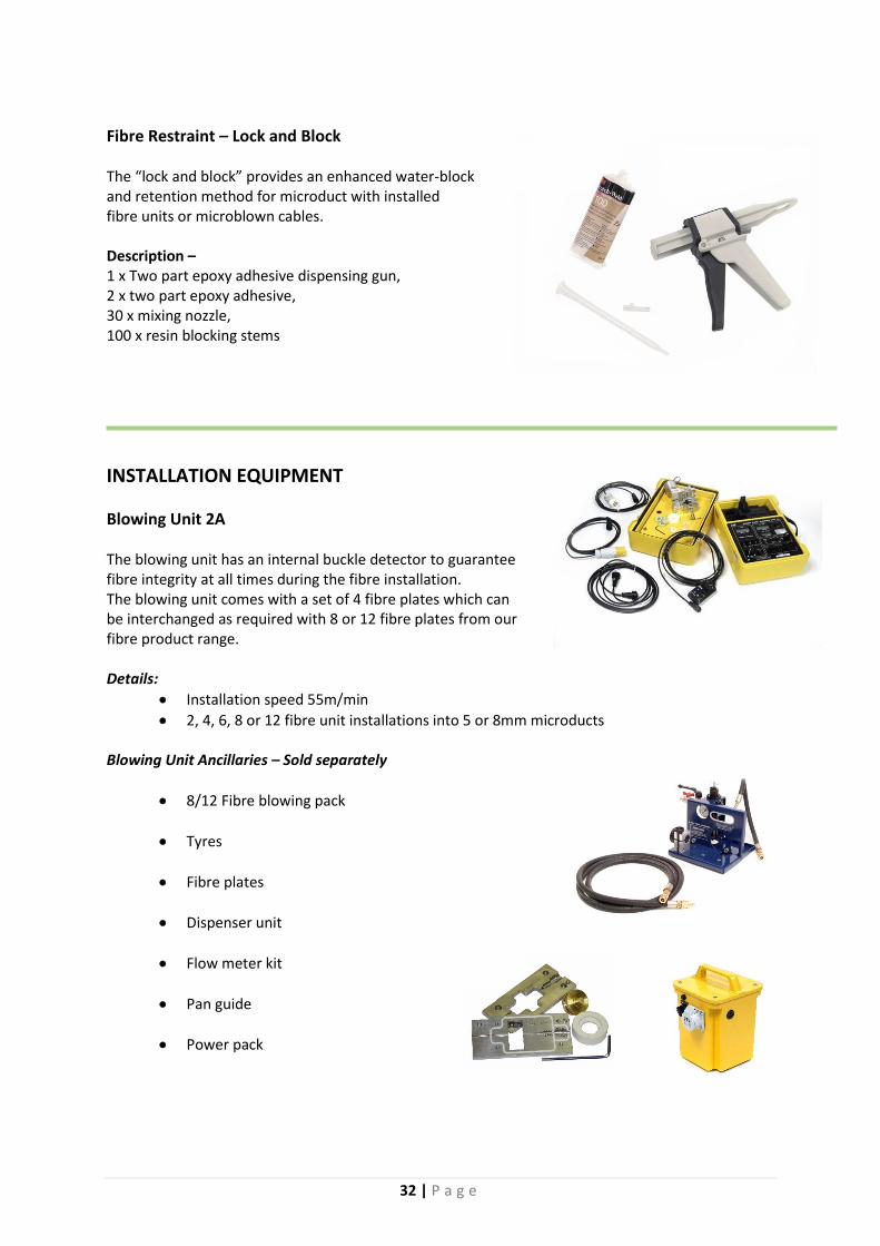
Fibre Restraint – Lock and Block The “lock and block” provides an enhanced water-block and retention method for microduct with installed fibre units or microblown cables. Description – 1 x Two part epoxy adhesive dispensing gun, 2 x two part epoxy adhesive, 30 x mixing nozzle, 100 x resin blocking stems
INSTALLATION EQUIPMENT
Blowing Unit 2A The blowing unit has an internal buckle detector to guarantee fibre integrity at all times during the fibre installation. The blowing unit comes with a set of 4 fibre plates which can be interchanged as required with 8 or 12 fibre plates from our fibre product range. Details:
Installation speed 55m/min
2, 4, 6, 8 or 12 fibre unit installations into 5 or 8mm microducts Blowing Unit Ancillaries – Sold separately
8/12 Fibre blowing pack
Tyres
Fibre plates
Dispenser unit
Flow meter kit
Pan guide
Power pack

33 | P a g e
Airstream The airstream is suitable for installing micro/mini cables ranging from 2.5 – 11.0mm. The machine features a high or low adjustable torque setting to protect the cables. This also aids in the installation of small cables.
TOOLS
Plastic Shears
50mm OD microducts
Rotational Sheath Stripper
Suitable for microduct from 12mm to 44mm
Longitude Sheath Stripper
Stripping outer sheaths of microduct without damage – Window Cut
Primary Tube Cutter
This tool gives a clean, straight cut to primary tube.
34 | P a g e
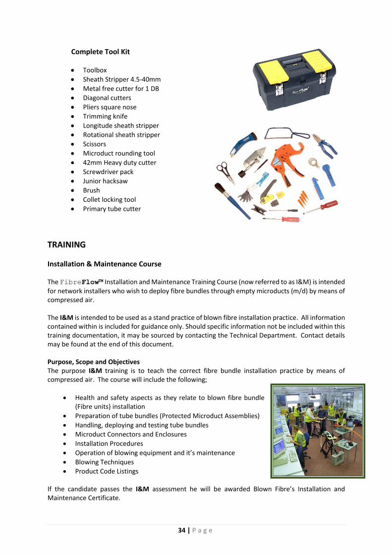
Complete Tool Kit
Toolbox
Sheath Stripper 4.5-40mm
Metal free cutter for 1 DB
Diagonal cutters
Pliers square nose
Trimming knife
Longitude sheath stripper
Rotational sheath stripper
Scissors
Microduct rounding tool
42mm Heavy duty cutter
Screwdriver pack
Junior hacksaw
Brush
Collet locking tool
Primary tube cutter
TRAINING
Installation & Maintenance Course The FibreFlow™ Installation and Maintenance Training Course (now referred to as I&M) is intended
for network installers who wish to deploy fibre bundles through empty microducts (m/d) by means of compressed air. The I&M is intended to be used as a stand practice of blown fibre installation practice. All information contained within is included for guidance only. Should specific information not be included within this training documentation, it may be sourced by contacting the Technical Department. Contact details may be found at the end of this document. Purpose, Scope and Objectives The purpose I&M training is to teach the correct fibre bundle installation practice by means of compressed air. The course will include the following;
Health and safety aspects as they relate to blown fibre bundle (Fibre units) installation
Preparation of tube bundles (Protected Microduct Assemblies)
Handling, deploying and testing tube bundles
Microduct Connectors and Enclosures
Installation Procedures
Operation of blowing equipment and it’s maintenance
Blowing Techniques
Product Code Listings If the candidate passes the I&M assessment he will be awarded Blown Fibre’s Installation and Maintenance Certificate.

35 | P a g e
CONTACT DETAIL
ADDRESS 3 NAVVI STREET
ALBERTON NORTH GAUTENG
SOUTH AFRICA
TEL: +27(0)11 907 0879 FAX: +27(0)11 907 0894
E-MAIL: [email protected]
WEB: WWW.BLOWNFIBRE.CO.ZA