product – adc v11 and v12 - imagine · pdf fileit is not meant to describe the dtp...
TRANSCRIPT
Product – ADC v11 and v12
Topic: DTP Insertion Driver
Release Date: 26-March-2014
Revision History Revision Protocol Date Author Company Description
1.0 10/23/2010 Alexander Lazarevich Initial version
1.1 1/4/11 Product Marketing
Added more details within user note. Added IP Connection information.
1.2 8/16/11 Engineering Clarify DTP version, DTP driver use, and overcoming latency
1.3 12/16/11 Engineering Review updates and verbiage cleanup
1.4 4/20/2012
ADC v11.60 adds an Automatic Return function and an Instant Roll parameter to configuration.
1.5 7/13/2012 Joel Highet
Added clarification note on using DTP Insertion Driver and DTP 20 driver in conjunction. Driver support added to ADC v12.18.16 and higher.
1.6 3/25/2014 Rebranded to Imagine Communications
Version Compatibility
ADC™ Device Server: v11.59.4 or later, v12.18.16 or later
Air Client: v3.57.3 or later, v4.18.13 or later
Media Client: v3.57.4 or later, v4.18.8 or later 2014 Imagine Communications Corp. Proprietary and Confidential 26-March-2014| Page 1 of 18
DTP: DTP release Version 5.0.10 or later
*** If there are any changes made to the protocol/device impacting current implementation of the driver, the compatibility is NOT guaranteed.
Description This document describes the usage of DTP insertion driver in ADC™. It is not meant to describe the DTP device itself, so the device's manuals should be referred to get more detail information about the device. The DTP Insertion driver was introduced with ADC100 v11.57.11 and DTP software version 5.0.10 or later when using ADC control. For use of DTP Insertion Driver, it is required that compatible versions of clients are used (Air Client v3.57.3.0A or higher and Media Client v3.57.4.0A or higher). The driver talks to DTP using RCS (Remote Control System) protocol via TCP/IP. So, there should be TCP/IP connection between ADC100 and DTP. By default, it uses port number 49227. A java based GUI, jRCS (see image below) is provided and comes with DTP. Any java capable client PC can get the codes just by connecting to DTP. Please refer to DTP’s manual for the detail.
The DTP Insertion driver is intended to control Cueing and Splicing of clips and input programs with the DTP through the use of Primary or Secondary AV (SAV) events within the Transmission List. The device itself should be configured first as desired by using jRCS, then the driver can be configured in ADC100 based on the DTP’s configuration.
The DTP-20 driver is used primarily to control Logos and text, and text crawls within the DTP stream by using secondary A/V events for cueing and playing. The DTP Insertion driver uses Primary or Secondary AV (SAV) events and users can check the Device Storage window upon the Client applications to view the DTP clip storage.
Working in Conjunction: The DTP Insertion Driver can work in conjunction with ADC’s legacy DTP-20 Driver. These drivers can be assigned to the same ADC Playlist for dual control of the DTP (i.e. Both drivers can be assigned separately to the same ADC Playlist for playout of Clips, Input Programs, Graphics, and graphic effects.) In addition, when configuring the Communications parameters on each of our DTP drivers, they can both share the same cable, network IP address, and Port #.
Driver Use Note: If intending to utilize features on both DTP drivers, contact a Sales and Support to determine how both drivers can be enabled in your Device Server Build. jRCS Note: The jRCS Client version should match the DTP software version running. If it doesn’t match a warning message is displayed after login. Reference Note: Due to the latencies involved, specific techniques are used to time the DTP insertions. For more information refer to the “DTP Insertion Timing Instructions” Support document.
Summary of function lists
2014 Imagine Communications Corp. Proprietary and Confidential 26-March-2014| Page 2 of 18

Cueing and Splicing Cueing and splicing of clips and input programs to a configured DTP output program
Driver input programs and clips collection Viewing of DTP clips and, if configured, input programs at Air Client or Media Client storage window
Assigning output programs to driver streams Driver stream handles one DTP output program
Programs assignment is configurable at the driver configuration form
Supported events Primary or Secondary AV (sAV) events are supported
Supported Primary event types are A, AO (hard start) and U (up-count event) in combinations AU and AOU.
Recommend steps for the first time use of DTP driver 1. Assign correct IP address to DTP
2. Make sure DTP is running and every physical connection is firmly attached
3. Launch jRCS and by using it confirm the current set up and establish or report Program References. Reference Note: The customer will set up the PID layout for output and the system will discover ASI inputs dynamically and IP inputs dynamically once IP Address and Port are known.
4. For the broadcaster that wants to use ADC or 3rd party automation to control the DTPTM, a new dedicated API for simplified ad-insertion has been added that greatly simplifies automation complexity. With the new feature of ‘Program References’, a unique name can be applied to inputs and outputs, currently seen by the DTPTM or those named for future use. From the man menu select Configuration> Program References. The Manage Program Reference screen is displayed.
2014 Imagine Communications Corp. Proprietary and Confidential 26-March-2014| Page 3 of 18
5. Set Program references for all input and output programs. Ensure each program reference has an Active status.
6. Start ADC and configure the driver in Device Config window using Config tool (set IP, Port of DTP, Client ID, assign output programs to driver streams).
7. Assign each stream in the driver to a playlist in List Config window using Config tool • One DTP stream of the DTP Driver will support 2 heads within the ADC Transmission
list for back to back play of events
8. An ADC operator can assign 1 DTP stream per Playlist, or assign multiple DTP streams to a single ADC Playlist for multi head playout control. • ADC recommends assigning only one DTP Stream per ADC Playlist to ensure proper
splice control
*** More detail guide about the configuration will follow in later sections
Driver Limitations The driver does not support configuring or monitoring DTP. Please use jRCS for that
function.
If there are any changes in the input lists, reverify the driver using the Config tool.
If there are any changes in the output programs such as adding a new one or deleting an existing one, changes in program references, splice preroll of any program, re-initialize or re-verify the driver using the Config tool.
Cloning is not supported with the DTP Insertion Driver as it is an IP device driver.
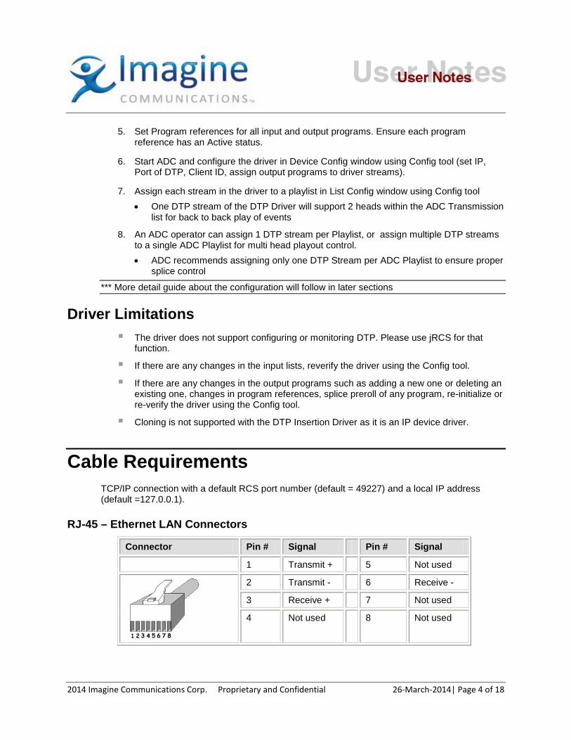
Cable Requirements TCP/IP connection with a default RCS port number (default = 49227) and a local IP address (default =127.0.0.1).
RJ-45 – Ethernet LAN Connectors
Connector Pin # Signal Pin # Signal
1 Transmit + 5 Not used
2 Transmit - 6 Receive -
3 Receive + 7 Not used
4 Not used 8 Not used
2014 Imagine Communications Corp. Proprietary and Confidential 26-March-2014| Page 4 of 18
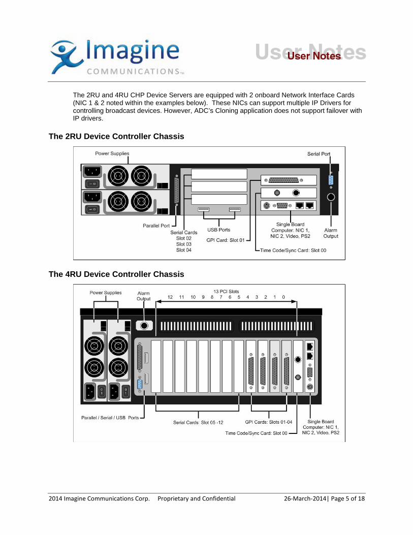
The 2RU and 4RU CHP Device Servers are equipped with 2 onboard Network Interface Cards (NIC 1 & 2 noted within the examples below). These NICs can support multiple IP Drivers for controlling broadcast devices. However, ADC’s Cloning application does not support failover with IP drivers.
The 2RU Device Controller Chassis
The 4RU Device Controller Chassis
2014 Imagine Communications Corp. Proprietary and Confidential 26-March-2014| Page 5 of 18

Key DTP Device Configuration Steps
Adding a new output program: Each output program must be created with enabling “Frame Accurate Splicing” option at Add Program window. The “Pre-Roll time” by default will be 1200 ms, but this value can be altered to adjust for environmental latencies.
Reference Note: Due to the latencies involved, specific techniques are used to time the DTP insertions. For more information refer to the “DTP Insertion Timing Instructions” Support document.
Adding a new program with the “Frame accurate Splicing” option enabled.
2014 Imagine Communications Corp. Proprietary and Confidential 26-March-2014| Page 6 of 18
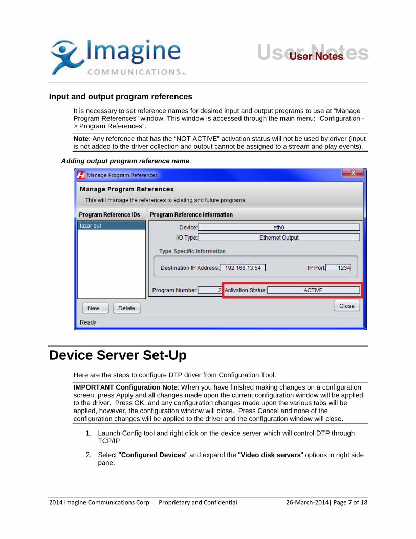
Input and output program references
It is necessary to set reference names for desired input and output programs to use at “Manage Program References” window. This window is accessed through the main menu: “Configuration -> Program References”.
Note: Any reference that has the “NOT ACTIVE” activation status will not be used by driver (input is not added to the driver collection and output cannot be assigned to a stream and play events).
Adding output program reference name
Device Server Set-Up Here are the steps to configure DTP driver from Configuration Tool.
IMPORTANT Configuration Note: When you have finished making changes on a configuration screen, press Apply and all changes made upon the current configuration window will be applied to the driver. Press OK, and any configuration changes made upon the various tabs will be applied, however, the configuration window will close. Press Cancel and none of the configuration changes will be applied to the driver and the configuration window will close.
1. Launch Config tool and right click on the device server which will control DTP through TCP/IP
2. Select "Configured Devices" and expand the "Video disk servers" options in right side pane.
2014 Imagine Communications Corp. Proprietary and Confidential 26-March-2014| Page 7 of 18
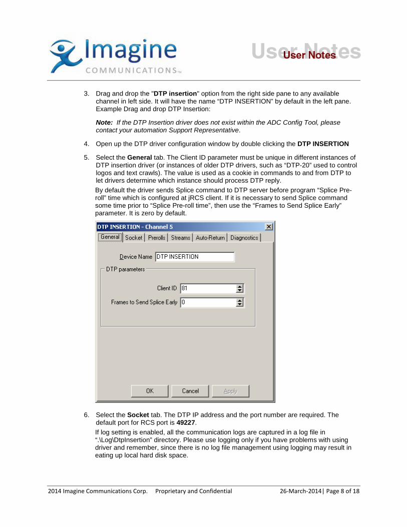
3. Drag and drop the "DTP insertion" option from the right side pane to any available channel in left side. It will have the name “DTP INSERTION” by default in the left pane. Example Drag and drop DTP Insertion:
Note: If the DTP Insertion driver does not exist within the ADC Config Tool, please contact your automation Support Representative.
4. Open up the DTP driver configuration window by double clicking the DTP INSERTION
5. Select the General tab. The Client ID parameter must be unique in different instances of DTP insertion driver (or instances of older DTP drivers, such as “DTP-20” used to control logos and text crawls). The value is used as a cookie in commands to and from DTP to let drivers determine which instance should process DTP reply. By default the driver sends Splice command to DTP server before program “Splice Pre-roll” time which is configured at jRCS client. If it is necessary to send Splice command some time prior to “Splice Pre-roll time”, then use the “Frames to Send Splice Early” parameter. It is zero by default.
6. Select the Socket tab. The DTP IP address and the port number are required. The default port for RCS port is 49227. If log setting is enabled, all the communication logs are captured in a log file in “.\Log\DtpInsertion” directory. Please use logging only if you have problems with using driver and remember, since there is no log file management using logging may result in eating up local hard disk space.
2014 Imagine Communications Corp. Proprietary and Confidential 26-March-2014| Page 8 of 18
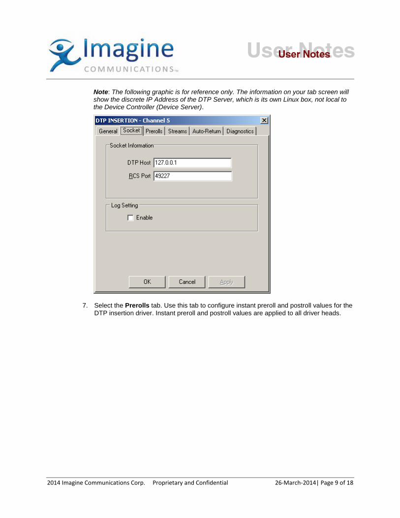
Note: The following graphic is for reference only. The information on your tab screen will show the discrete IP Address of the DTP Server, which is its own Linux box, not local to the Device Controller (Device Server).
7. Select the Prerolls tab. Use this tab to configure instant preroll and postroll values for the DTP insertion driver. Instant preroll and postroll values are applied to all driver heads.
2014 Imagine Communications Corp. Proprietary and Confidential 26-March-2014| Page 9 of 18

Configure the following parameters as required:
• Instant Prerolls. The Instant feature is designed for coming out of a live or upcounting event as fast as possible when the next event has a near instant preroll. If you are using a master control switcher, the preroll must not be shorter than the shortest preroll supported by the switcher.
Use Instant Prerolls. This function has a default of zero seconds, four frames. The values can range from four frames to 59 seconds. Instant Preroll provides instant play/skip capability to the device. When enabled, Instant Play Preroll is activated by pressing the Instant button or Roll Now button on the control panel. The preroll must be set to at least the minimum switcher preroll or the disk port may start playing before the switcher switches.
The preroll also must be set to at least four frames greater than the Disk Preroll and Number of Frames to Send Play Early. Four frames is the minimum preroll allowed by ADC. If not configured properly, the list may stop, or Roll Now may not work as expected, but take a longer time than desired.
If Instant Preroll is set longer than the List Preroll, instant play is actually a delayed play. ADC operations rely on list preroll settings configured through the Options menu, in Configure Lists.
• Device Postroll.
2014 Imagine Communications Corp. Proprietary and Confidential 26-March-2014| Page 10 of 18

Use Postroll. Default: Disabled, zero seconds, four frames. Range: four frames to 59 seconds. When enabled, this settings overrides other configured postroll settings. Device postroll, if enabled, must be set to at least 4 frames. This feature allows the list to use one postroll for VTRs, cart machines, and other devices, and a different postroll for video disks. The Device Postroll can be longer or shorter than the list postroll. Its main purpose is to clear out the disk status line quickly after the disk stops playing, so the status line can be loaded with the next event to cue. This allows small spots to be played back to back.
If the Device Postroll was set to a larger value, and the disk had over recorded the ID compared to the play duration, the disk would continue to play for the post roll duration if on air play switched to another device. This would permit mix effects during the post roll of the disk device into the play out from another device.
Seconds. Select a value of up to 59 seconds. Frames. Select a value of at least 4 frames. NOTE: The Seconds and Frames values have no effect unless the Use Postroll box is enabled (checked).
8. Select the Streams tab. This tab allows the mapping any of active DTP output program to any available stream using drag and drop. The mechanism is similar to assigning driver streams to lists. During configuration of multiple instances of this driver which will communicate with a single DTP, output programs must not be assigned to more than one stream in different instances. Note: If any assigned to stream program was deleted or become not active after the driver re-initializes, the stream heads must have “OFFLINE” status at Device status window.
Note: Only Active output program references are displayed at Available list.
2014 Imagine Communications Corp. Proprietary and Confidential 26-March-2014| Page 11 of 18

9. Select the AutoReturn tab. This tab is used to set – by stream - the input program which will be spliced after clip insertion. Requirements: The following requirements must be met for this feature to work:
“Auto Ripple Times” option at “Options” tab of the list properties window must be enabled for correct operation of the Auto-Return feature. The option must be enabled for all lists which will run DTP Insertion events with enabled Auto-Return.
An Input reference, which will be set as default Source (Auto-Return program), must be active.
About points A and C from MRD ({Clip Playing} / {Clip Cued} -> {Clip Cued} / {Idle} and .{Clip Playing} / {Source Cued} -> {Source Cued} / {Idle}). The recommended minimal interval between the end of the first event (not postroll) and preroll of the second one is 3 seconds. Splice to the second event can fail If the interval is lesser then 3 seconds. The back to back splice is not affected.
2014 Imagine Communications Corp. Proprietary and Confidential 26-March-2014| Page 12 of 18
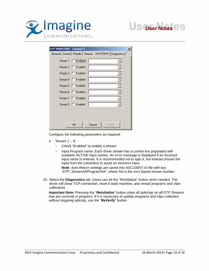
Configure the following parameters as required:
• Stream 1 – 8: Check “Enabled” to enable a stream. Input Program name: Each driver stream has a combo box populated with
available ACTIVE input names. An error message is displayed if an incorrect input name is entered. It is recommended not to type it, but instead choose the input from the combobox to avoid an incorrect input. Note: Auto-Return settings are saved into ADC100NT.ini file with key “DTP_StreamARProgram%d”, where %d is the zero based stream number.
10. Select the Diagnostics tab. Users can hit the “Reinitialize” button when needed. The driver will close TCP connection, reset it state machine, and reread programs and clips collections. Important Note: Pressing the “Reinitialize” button stops all splicings on all DTP Streams that are currently in progress. If it is necessary to update programs and clips collection without stopping splicing, use the “ReVerify” button.
2014 Imagine Communications Corp. Proprietary and Confidential 26-March-2014| Page 13 of 18

11. Closing Device configuration prompts to save the configuration. The configuration information is saved to the ADC ini file (e.g. "ADC100NT.INI").
List Configuration Use the steps to assign pre-configured program outputs in DTP to playlists in ADC100 from Configuration Tool.
1. Launch Config tool and right click on the Device Server which will control DTP through TCP/IP.
2. Select "List Configuration". There should be a tree with name, DTP INSERTION, in right side pane or another name if the DTP driver is given a name different than the default.
2014 Imagine Communications Corp. Proprietary and Confidential 26-March-2014| Page 14 of 18

3. Drag and drop a DTP stream, STRM:1~n, to a desired playlist in the left side pane • As noted previously, it is recommended to assign only one DTP stream per Playlist.
4. Closing List configuration prompts to save the configuration. The configuration information is saved to "LISTCONF.INI".
Operation Notes
Storage window The Storage window of Air Client and Media Client allows viewing of DTP input programs and clips collections. The active input programs are displayed at the top of a spot list and they have reference name, configured ad jRCS, and ID. Clips are displayed after programs when viewing the Storage Window. The clips collection automatically updates after changes at DTP storage (any clip was added or deleted). The inputs collection does not automatically update. After any change in to the input list
2014 Imagine Communications Corp. Proprietary and Confidential 26-March-2014| Page 15 of 18

at jRCS client, it is recommended to manually launch “ReVerify” from the driver diagnostics configuration tab.
Note: Only Active input program references are added to the driver inputs collection. Note: Currently DTP does not support all codecs for clips. For clips with unsupported codecs, the duration will be zero and they should not be used for splicing. IMPORTANT: Air Client versions prior to v3.59 will not work. Air Client v3.59 or higher is required.
Figure 11: Storage window
Event Creation Once a playlist is configured to have a stream of a DTP driver by list configuration, all the events regarding DTP in the list are applied to the specific stream which in turn is associated with a certain output program in DTP.
The Driver supports Primary and Secondary AV events for splicing input programs and clips. Primary events could be added to playlist using drag and drop from Storage window to Playlist window. Supported primary event types are:
A (automatic)
AO (hard start, automatic)
U (up-count) in combinations AU and AOU, but only for splicing input programs. Supported Secondary event types are:
2014 Imagine Communications Corp. Proprietary and Confidential 26-March-2014| Page 16 of 18
The only secondary event supported by the DTP Insertion driver is Secondary AV (sAV).
To know more about event types please refer to Air Client Operations Reference manual..Note: If the files put into the DTP have extensions, then the clip names reported to ADC in the storage window will have the extension and the clip name with the extension has to be used in the ADC list. However, extensions aren’t needed by the DTP for clips- it will play viable clips regardless of the extension or lack of one. Therefore, it is recommended that whatever process is used to place, move, or transcode clips into the DTP not utilize extensions, and any existing extensions be removed in the transcoding or transfer process.
Playout After driver initialized or re-initialized it stops splicing on output programs which it handles. After stream stops playing (play list is unthreaded or empty) driver also stops splicing. Stream mapped to an active output will have “Standby” status at Device status window. And stream mapped to a not active output or not mapped at all will have “OFFLINE” status. IDs within the ADC Playlist which are not reported by the DTP Storage will not Cue or Play. These events will be missed unless a re-verify upon the DTP Insertion driver corrects the problem.
Note: Due to the latencies involved, specific techniques are used to time the DTP insertions. Refer to “DTP Insertion Timing Instructions” Support document for further information. Note: The DTP itself cannot guarantee frame accurate splicing under all conditions. Refer to the DTP documentation for further information. (Example is a splicing between separate network inputs).
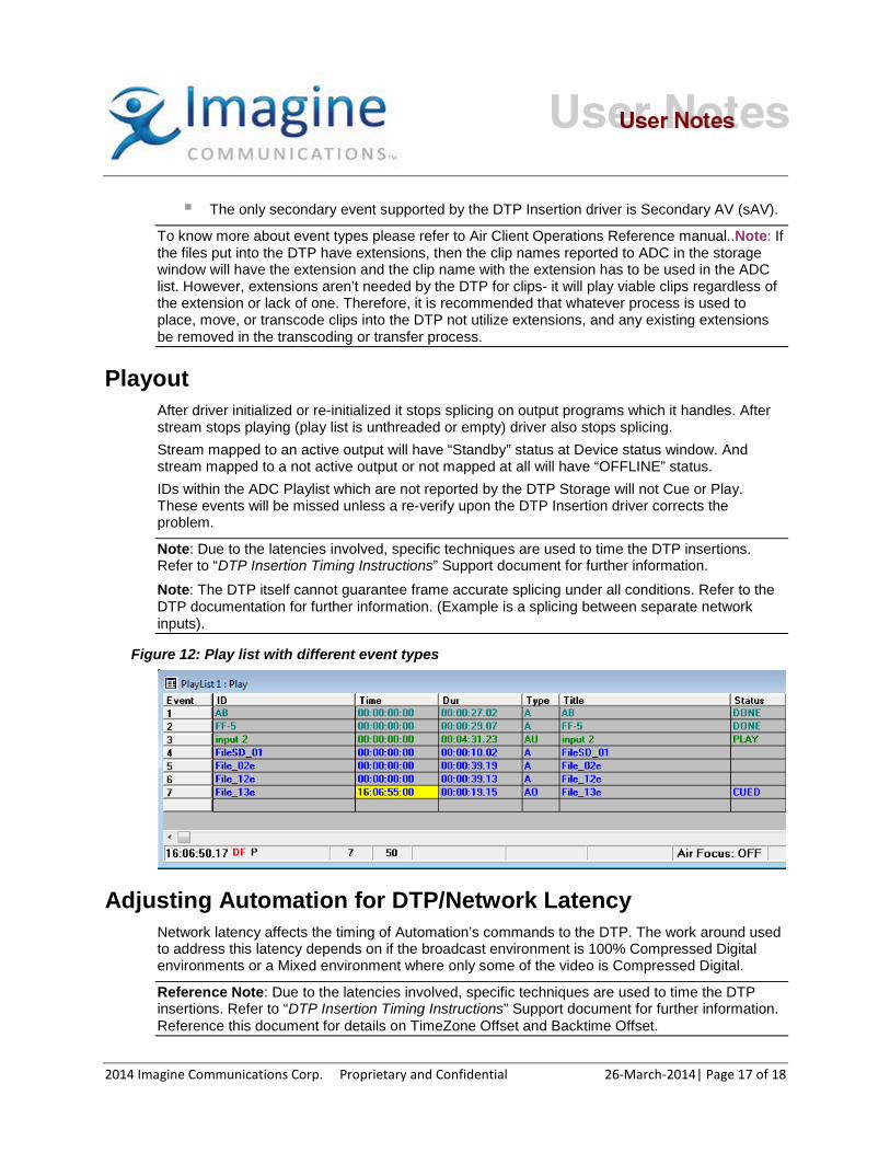
Figure 12: Play list with different event types
Adjusting Automation for DTP/Network Latency Network latency affects the timing of Automation’s commands to the DTP. The work around used to address this latency depends on if the broadcast environment is 100% Compressed Digital environments or a Mixed environment where only some of the video is Compressed Digital.
Reference Note: Due to the latencies involved, specific techniques are used to time the DTP insertions. Refer to “DTP Insertion Timing Instructions” Support document for further information. Reference this document for details on TimeZone Offset and Backtime Offset.
2014 Imagine Communications Corp. Proprietary and Confidential 26-March-2014| Page 17 of 18

Internal Document # xxxxx
File xxxxx
2014 Imagine Communications Corp. Proprietary and Confidential 26-March-2014| Page 18 of 18