processor memory gap - university of houston-clear...
TRANSCRIPT
1
Chapter 8 <1>
Digital Design and Computer Architecture, 2nd Edition
Chapter 8
David Money Harris and Sarah L. Harris
Chapter 8 <2>
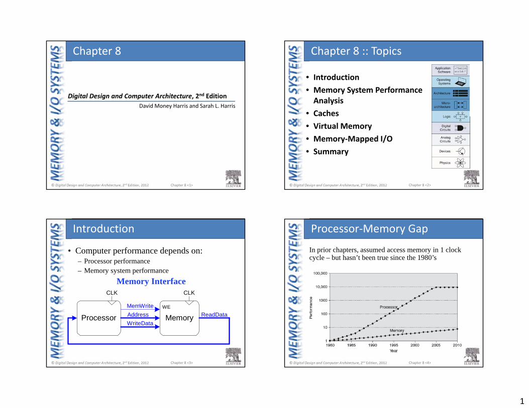
Chapter 8 :: Topics
• Introduction• Memory System Performance Analysis
• Caches• Virtual Memory• Memory‐Mapped I/O• Summary
Chapter 8 <3>
Processor MemoryAddressMemWrite
WriteDataReadData
WE
CLKCLK
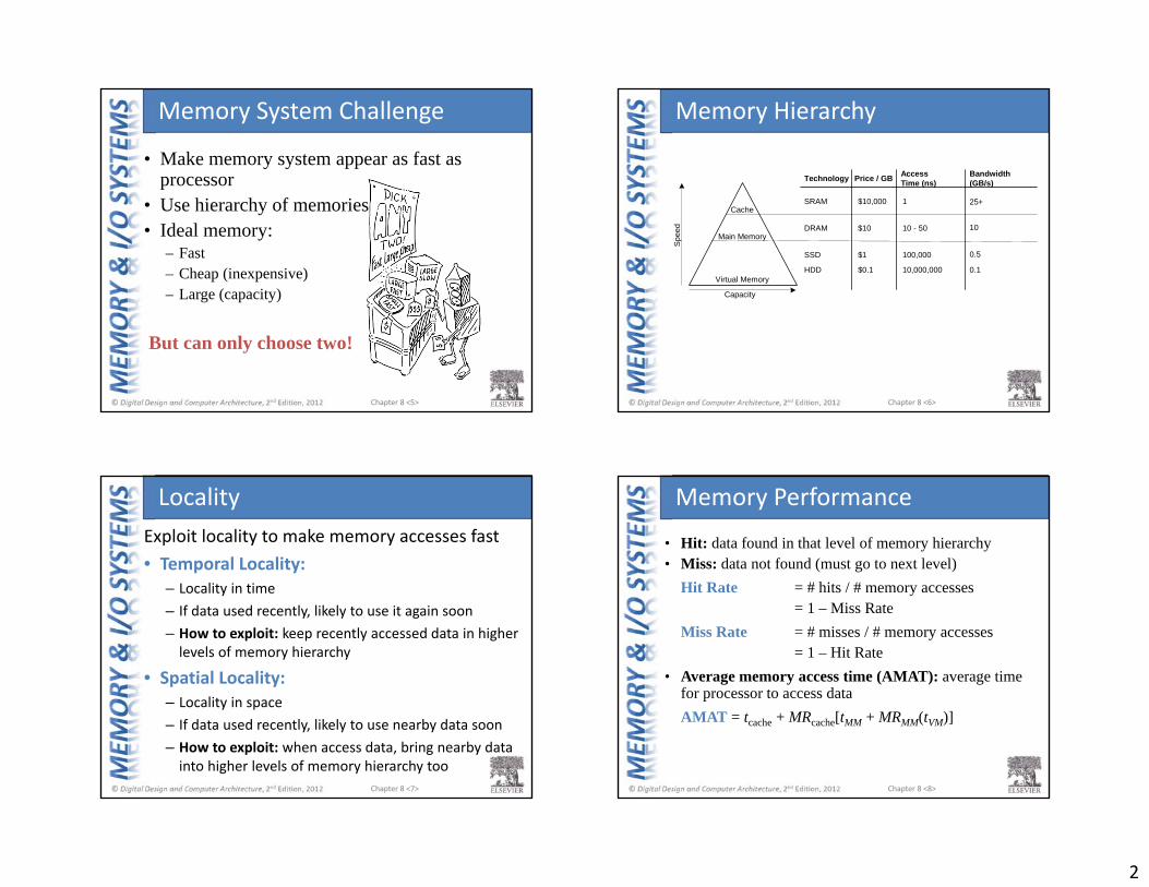
• Computer performance depends on:– Processor performance– Memory system performance
Memory Interface
Introduction
Chapter 8 <4>
In prior chapters, assumed access memory in 1 clock cycle – but hasn’t been true since the 1980’s
Processor‐Memory Gap
2
Chapter 8 <5>
• Make memory system appear as fast as processor
• Use hierarchy of memories• Ideal memory:
– Fast– Cheap (inexpensive)– Large (capacity)
But can only choose two!
Memory System Challenge
Chapter 8 <6>
Memory Hierarchy
Technology Price / GB AccessTime (ns)
Bandwidth(GB/s)
Cache
Main Memory
Virtual Memory
Capacity
Spe
ed
SRAM $10,000 1
DRAM $10 10 - 50
SSD $1 100,000
25+
10
0.5
0.1HDD $0.1 10,000,000
Chapter 8 <7>
Exploit locality to make memory accesses fast• Temporal Locality:
– Locality in time– If data used recently, likely to use it again soon– How to exploit: keep recently accessed data in higher levels of memory hierarchy
• Spatial Locality:– Locality in space– If data used recently, likely to use nearby data soon– How to exploit: when access data, bring nearby data into higher levels of memory hierarchy too
Locality
Chapter 8 <8>
• Hit: data found in that level of memory hierarchy• Miss: data not found (must go to next level)
Hit Rate = # hits / # memory accesses= 1 – Miss Rate
Miss Rate = # misses / # memory accesses= 1 – Hit Rate
• Average memory access time (AMAT): average time for processor to access dataAMAT = tcache + MRcache[tMM + MRMM(tVM)]
Memory Performance
3
Chapter 8 <9>
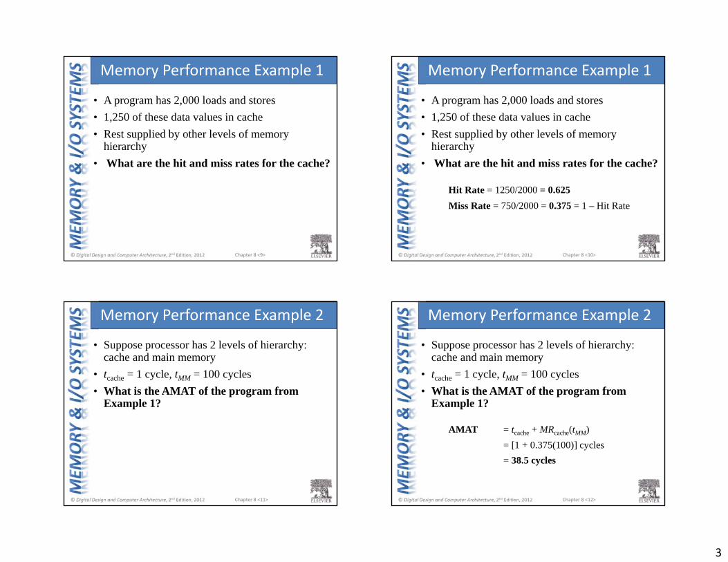
• A program has 2,000 loads and stores• 1,250 of these data values in cache• Rest supplied by other levels of memory
hierarchy• What are the hit and miss rates for the cache?
Memory Performance Example 1
Chapter 8 <10>
• A program has 2,000 loads and stores• 1,250 of these data values in cache• Rest supplied by other levels of memory
hierarchy• What are the hit and miss rates for the cache?
Hit Rate = 1250/2000 = 0.625Miss Rate = 750/2000 = 0.375 = 1 – Hit Rate
Memory Performance Example 1
Chapter 8 <11>
• Suppose processor has 2 levels of hierarchy: cache and main memory
• tcache = 1 cycle, tMM = 100 cycles• What is the AMAT of the program from
Example 1?
Memory Performance Example 2
Chapter 8 <12>
• Suppose processor has 2 levels of hierarchy: cache and main memory
• tcache = 1 cycle, tMM = 100 cycles• What is the AMAT of the program from
Example 1?
AMAT = tcache + MRcache(tMM)= [1 + 0.375(100)] cycles= 38.5 cycles
Memory Performance Example 2
4
Chapter 8 <13>
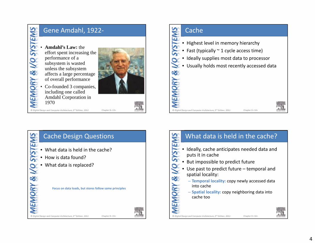
• Amdahl’s Law: the effort spent increasing the performance of a subsystem is wasted unless the subsystem affects a large percentage of overall performance
• Co-founded 3 companies, including one called Amdahl Corporation in 1970
Gene Amdahl, 1922‐
Chapter 8 <14>
• Highest level in memory hierarchy• Fast (typically ~ 1 cycle access time)• Ideally supplies most data to processor• Usually holds most recently accessed data
Cache
Chapter 8 <15>
• What data is held in the cache?• How is data found?• What data is replaced?
Focus on data loads, but stores follow same principles
Cache Design Questions
Chapter 8 <16>
• Ideally, cache anticipates needed data and puts it in cache
• But impossible to predict future• Use past to predict future – temporal and spatial locality:– Temporal locality: copy newly accessed data into cache
– Spatial locality: copy neighboring data into cache too
What data is held in the cache?
5
Chapter 8 <17>
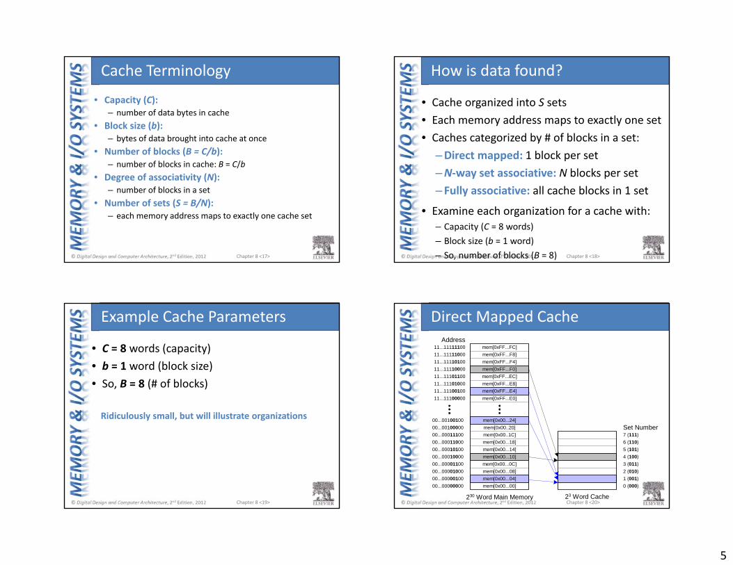
• Capacity (C): – number of data bytes in cache
• Block size (b): – bytes of data brought into cache at once
• Number of blocks (B = C/b): – number of blocks in cache: B = C/b
• Degree of associativity (N): – number of blocks in a set
• Number of sets (S = B/N): – each memory address maps to exactly one cache set
Cache Terminology
Chapter 8 <18>
• Cache organized into S sets• Each memory address maps to exactly one set• Caches categorized by # of blocks in a set:
–Direct mapped: 1 block per set–N‐way set associative: N blocks per set– Fully associative: all cache blocks in 1 set
• Examine each organization for a cache with:– Capacity (C = 8 words)– Block size (b = 1 word)– So, number of blocks (B = 8)
How is data found?
Chapter 8 <19>
• C = 8 words (capacity)• b = 1 word (block size)• So, B = 8 (# of blocks)
Ridiculously small, but will illustrate organizations
Example Cache Parameters
Chapter 8 <20>
7 (111)
00...00010000
230 Word Main Memory
mem[0x00...00]mem[0x00...04]mem[0x00...08]mem[0x00...0C]mem[0x00...10]mem[0x00...14]mem[0x00...18]mem[0x00..1C]mem[0x00..20]mem[0x00...24]
mem[0xFF...E0]mem[0xFF...E4]mem[0xFF...E8]mem[0xFF...EC]mem[0xFF...F0]mem[0xFF...F4]mem[0xFF...F8]mem[0xFF...FC]
23 Word Cache
Set Number
Address
00...0000000000...0000010000...0000100000...00001100
00...0001010000...0001100000...0001110000...0010000000...00100100
11...11110000
11...1110000011...1110010011...1110100011...11101100
11...1111010011...1111100011...11111100
6 (110)5 (101)4 (100)3 (011)2 (010)1 (001)0 (000)
Direct Mapped Cache
6
Chapter 8 <21>
DataTag
00Tag Set
ByteOffsetMemory
Address
DataHit
V
=
27 3
27 32
8-entry x(1+27+32)-bit
SRAM
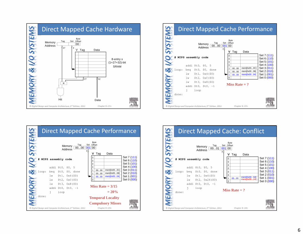
Direct Mapped Cache Hardware
Chapter 8 <22>
# MIPS assembly code
addi $t0, $0, 5loop: beq $t0, $0, done
lw $t1, 0x4($0)lw $t2, 0xC($0)lw $t3, 0x8($0)addi $t0, $t0, -1j loop
done:
DataTagV
00...001 mem[0x00...04]
000
0
0
00Tag Set
ByteOffsetMemory
AddressV
300100...00
100...0000...00
1
mem[0x00...0C]mem[0x00...08]
Set 7 (111)Set 6 (110)Set 5 (101)Set 4 (100)Set 3 (011)Set 2 (010)Set 1 (001)Set 0 (000)
Miss Rate = ?
Direct Mapped Cache Performance
Chapter 8 <23>
# MIPS assembly code
addi $t0, $0, 5loop: beq $t0, $0, done
lw $t1, 0x4($0)lw $t2, 0xC($0)lw $t3, 0x8($0)addi $t0, $t0, -1j loop
done:
DataTagV
00...001 mem[0x00...04]
000
0
0
00Tag Set
ByteOffsetMemory
AddressV
300100...00
100...0000...00
1
mem[0x00...0C]mem[0x00...08]
Set 7 (111)Set 6 (110)Set 5 (101)Set 4 (100)Set 3 (011)Set 2 (010)Set 1 (001)Set 0 (000)
Miss Rate = 3/15= 20%
Temporal LocalityCompulsory Misses
Direct Mapped Cache Performance
Chapter 8 <24>
# MIPS assembly code
addi $t0, $0, 5loop: beq $t0, $0, done
lw $t1, 0x4($0)lw $t2, 0x24($0)addi $t0, $t0, -1j loop
done:
DataTagV
00...001 mem[0x00...04]
000
0
0
00Tag Set
ByteOffsetMemory
AddressV
300100...01
00
Set 7 (111)Set 6 (110)Set 5 (101)Set 4 (100)Set 3 (011)Set 2 (010)Set 1 (001)Set 0 (000)
mem[0x00...24]
Miss Rate = ?
Direct Mapped Cache: Conflict
7
Chapter 8 <25>
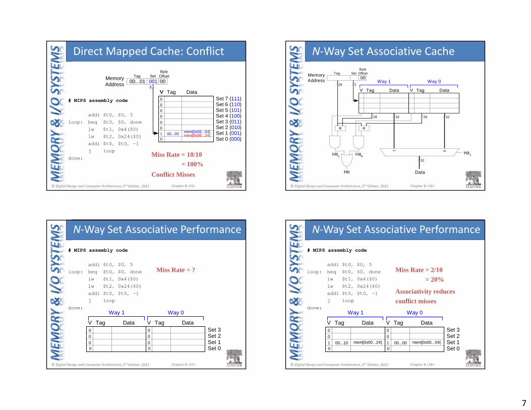
# MIPS assembly code
addi $t0, $0, 5loop: beq $t0, $0, done
lw $t1, 0x4($0)lw $t2, 0x24($0)addi $t0, $t0, -1j loop
done:
DataTagV
00...001 mem[0x00...04]
000
0
0
00Tag Set
ByteOffsetMemory
AddressV
300100...01
00
Set 7 (111)Set 6 (110)Set 5 (101)Set 4 (100)Set 3 (011)Set 2 (010)Set 1 (001)Set 0 (000)
mem[0x00...24]
Miss Rate = 10/10= 100%
Conflict Misses
Direct Mapped Cache: Conflict
Chapter 8 <26>
DataTag
Tag SetByte
OffsetMemoryAddress
Data
Hit1
V
=
01
00
32 32
32
DataTagV
=
Hit1Hit0
Hit
28 2
28 28
Way 1 Way 0
N‐Way Set Associative Cache
Chapter 8 <27>
# MIPS assembly code
addi $t0, $0, 5loop: beq $t0, $0, done
lw $t1, 0x4($0)lw $t2, 0x24($0)addi $t0, $t0, -1j loop
done:
DataTagV DataTagV
0 0
00
0
00
0
Way 1 Way 0
Set 3Set 2Set 1Set 0
Miss Rate = ?
N‐Way Set Associative Performance
Chapter 8 <28>
# MIPS assembly code
addi $t0, $0, 5loop: beq $t0, $0, done
lw $t1, 0x4($0)lw $t2, 0x24($0)addi $t0, $t0, -1j loop
done:
DataTagV DataTagV
00...001 mem[0x00...04]00...10 1mem[0x00...24]
00
0
00
0
Way 1 Way 0
Set 3Set 2Set 1Set 0
Miss Rate = 2/10 = 20%
Associativity reducesconflict misses
N‐Way Set Associative Performance
8
Chapter 8 <29>
DataTagV DataTagV DataTagV DataTagV DataTagV DataTagV DataTagV DataTagV
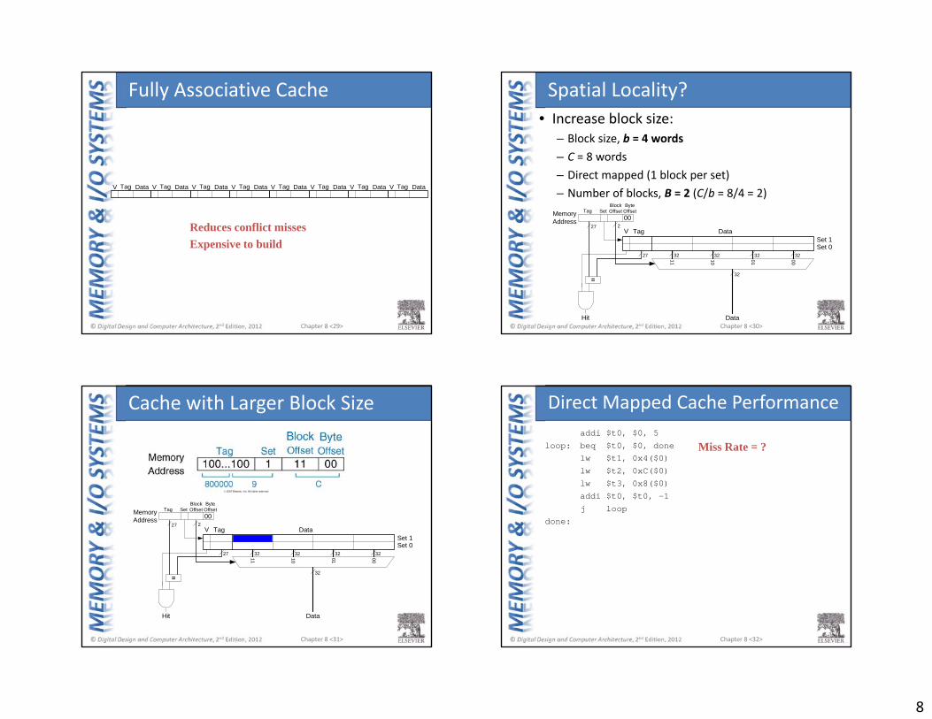
Reduces conflict missesExpensive to build
Fully Associative Cache
Chapter 8 <30>
• Increase block size:– Block size, b = 4 words– C = 8 words– Direct mapped (1 block per set)– Number of blocks, B = 2 (C/b = 8/4 = 2)
DataTag
00Tag
ByteOffsetMemory
Address
Data
V
00011011
BlockOffset
32 32 32 32
32
Hit
=
Set
27
27 2
Set 1Set 0
Spatial Locality?
Chapter 8 <31>
DataTag
00Tag
ByteOffsetMemory
Address
Data
V
00011011
BlockOffset
32 32 32 32
32
Hit
=
Set
27
27 2
Set 1Set 0
Cache with Larger Block Size
Chapter 8 <32>
addi $t0, $0, 5loop: beq $t0, $0, done
lw $t1, 0x4($0)lw $t2, 0xC($0)lw $t3, 0x8($0)addi $t0, $t0, -1j loop
done:
Miss Rate = ?
Direct Mapped Cache Performance
9
Chapter 8 <33>
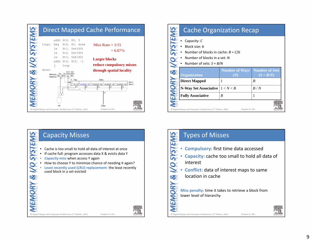
addi $t0, $0, 5loop: beq $t0, $0, done
lw $t1, 0x4($0)lw $t2, 0xC($0)lw $t3, 0x8($0)addi $t0, $t0, -1j loop
done:
00...00 0 11
DataTag
00Tag
ByteOffsetMemory
Address
Data
V
00011011
BlockOffset
32 32 32 32
32
Hit
=
Set
27
27 2
Set 1Set 000...001 mem[0x00...0C]
0mem[0x00...08] mem[0x00...04] mem[0x00...00]
Miss Rate = 1/15 = 6.67%
Larger blocksreduce compulsory missesthrough spatial locality
Direct Mapped Cache Performance
Chapter 8 <34>
• Capacity: C • Block size: b• Number of blocks in cache: B = C/b• Number of blocks in a set: N• Number of sets: S = B/N
OrganizationNumber of Ways
(N)Number of Sets
(S = B/N)Direct Mapped 1 B
N-Way Set Associative 1 < N < B B / N
Fully Associative B 1
Cache Organization Recap
Chapter 8 <35>
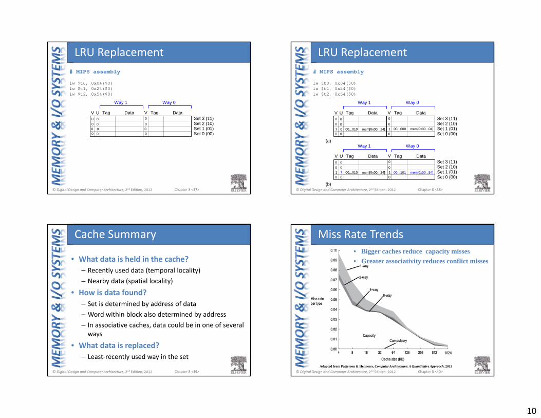
• Cache is too small to hold all data of interest at once• If cache full: program accesses data X & evicts data Y• Capacity miss when access Y again• How to choose Y to minimize chance of needing it again? • Least recently used (LRU) replacement: the least recently
used block in a set evicted
Capacity Misses
Chapter 8 <36>
• Compulsory: first time data accessed• Capacity: cache too small to hold all data of interest
• Conflict: data of interest maps to same location in cache
Miss penalty: time it takes to retrieve a block from lower level of hierarchy
Types of Misses
10
Chapter 8 <37>
DataTagV0
DataTagV0
0
0
0
0
U
0 0
00
00
Way 1 Way 0
Set 3 (11)Set 2 (10)Set 1 (01)Set 0 (00)
# MIPS assembly
lw $t0, 0x04($0)lw $t1, 0x24($0)lw $t2, 0x54($0)
LRU Replacement
Chapter 8 <38>
DataTagV0
DataTagV0
0
0
0
0
U
mem[0x00...04]1 00...000mem[0x00...24] 100...010
00
00
DataTagV0
DataTagV0
0
0
0
0
U
mem[0x00...54]1 00...101mem[0x00...24] 100...010
00
01
(a)
(b)
Way 1 Way 0
Way 1 Way 0
Set 3 (11)Set 2 (10)Set 1 (01)Set 0 (00)
Set 3 (11)Set 2 (10)Set 1 (01)Set 0 (00)
# MIPS assembly
lw $t0, 0x04($0)lw $t1, 0x24($0)lw $t2, 0x54($0)
LRU Replacement
Chapter 8 <39>
• What data is held in the cache?– Recently used data (temporal locality)– Nearby data (spatial locality)
• How is data found?– Set is determined by address of data– Word within block also determined by address– In associative caches, data could be in one of several ways
• What data is replaced?– Least‐recently used way in the set
Cache Summary
Chapter 8 <40>
• Bigger caches reduce capacity misses• Greater associativity reduces conflict misses
Adapted from Patterson & Hennessy, Computer Architecture: A Quantitative Approach, 2011
Miss Rate Trends

11
Chapter 8 <41>
• Bigger blocks reduce compulsory misses• Bigger blocks increase conflict misses
Miss Rate Trends
Chapter 8 <42>
• Larger caches have lower miss rates, longer access times
• Expand memory hierarchy to multiple levels of caches
• Level 1: small and fast (e.g. 16 KB, 1 cycle)• Level 2: larger and slower (e.g. 256 KB, 2‐6 cycles)
• Most modern PCs have L1, L2, and L3 cache
Multilevel Caches
Chapter 8 <43>
Intel Pentium III Die
Chapter 8 <44>
• Gives the illusion of bigger memory• Main memory (DRAM) acts as cache for hard disk
Virtual Memory

12
Chapter 8 <45>
• Physical Memory: DRAM (Main Memory)• Virtual Memory: Hard drive
– Slow, Large, Cheap
Memory Hierarchy
Technology Price / GB AccessTime (ns)
Bandwidth(GB/s)
Cache
Main Memory
Virtual Memory
Capacity
Spe
ed
SRAM $10,000 1
DRAM $10 10 - 50
SSD $1 100,000
25+
10
0.5
0.1HDD $0.1 10,000,000
Chapter 8 <46>
Read/WriteHead
MagneticDisks
Takes milliseconds to seek correct location on disk
Hard Disk
Chapter 8 <47>
• Virtual addresses– Programs use virtual addresses– Entire virtual address space stored on a hard drive– Subset of virtual address data in DRAM– CPU translates virtual addresses into physical addresses
(DRAM addresses)– Data not in DRAM fetched from hard drive
• Memory Protection– Each program has own virtual to physical mapping– Two programs can use same virtual address for different data– Programs don’t need to be aware others are running– One program (or virus) can’t corrupt memory used by
another
Virtual Memory
Chapter 8 <48>
Cache Virtual MemoryBlock Page
Block Size Page Size
Block Offset Page Offset
Miss Page Fault
Tag Virtual Page Number
Physical memory acts as cache for virtual memory
Cache/Virtual Memory Analogues

13
Chapter 8 <49>
• Page size: amount of memory transferred from hard disk to DRAM at once
• Address translation: determining physical address from virtual address
• Page table: lookup table used to translate virtual addresses to physical addresses
Virtual Memory Definitions
Chapter 8 <50>
Most accesses hit in physical memoryBut programs have the large capacity of virtual memory
Virtual & Physical Addresses
Chapter 8 <51>
Address Translation
Chapter 8 <52>
• System:– Virtual memory size: 2 GB = 231 bytes– Physical memory size: 128 MB = 227 bytes– Page size: 4 KB = 212 bytes
Virtual Memory Example
14
Chapter 8 <53>
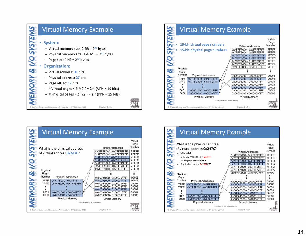
• System:– Virtual memory size: 2 GB = 231 bytes– Physical memory size: 128 MB = 227 bytes– Page size: 4 KB = 212 bytes
• Organization:– Virtual address: 31 bits– Physical address: 27 bits– Page offset: 12 bits– # Virtual pages = 231/212 = 219 (VPN = 19 bits)– # Physical pages = 227/212 = 215 (PPN = 15 bits)
Virtual Memory Example
Chapter 8 <54>
• 19‐bit virtual page numbers• 15‐bit physical page numbers
Virtual Memory Example
Chapter 8 <55>
Virtual Memory Example
What is the physical address of virtual address 0x247C?
Chapter 8 <56>
Virtual Memory ExampleWhat is the physical address of virtual address 0x247C?
– VPN = 0x2– VPN 0x2 maps to PPN 0x7FFF– 12‐bit page offset: 0x47C– Physical address = 0x7FFF47C
15
Chapter 8 <57>
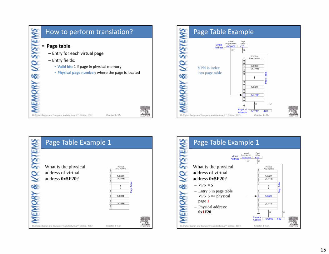
• Page table– Entry for each virtual page– Entry fields:
• Valid bit: 1 if page in physical memory• Physical page number: where the page is located
How to perform translation?
Chapter 8 <58>
001 0x00001 0x7FFE00
001 0x0001001 0x7FFF00
V
VirtualAddress 0x00002 47C
Hit
PhysicalPage Number
1219
15 12
VirtualPage Number
Pag
e Ta
ble
PageOffset
PhysicalAddress 0x7FFF 47C
VPN is index into page table
Page Table Example
Chapter 8 <59>
001 0x00001 0x7FFE00
001 0x0001001 0x7FFF00
VPhysical
Page Number
Pag
e Ta
ble
What is the physical address of virtual address 0x5F20?
Page Table Example 1
Chapter 8 <60>
001 0x00001 0x7FFE00
001 0x0001001 0x7FFF00
V
VirtualAddress 0x00005 F20
Hit
PhysicalPage Number
1219
15 12
VirtualPage Number
Pag
e Ta
ble
PageOffset
PhysicalAddress 0x0001 F20
What is the physical address of virtual address 0x5F20?– VPN = 5– Entry 5 in page table
VPN 5 => physical page 1
– Physical address: 0x1F20
Page Table Example 1
16
Chapter 8 <61>
001 0x00001 0x7FFE00
001 0x0001001 0x7FFF00
V
VirtualAddress 0x00007 3E0
Hit
PhysicalPage Number
19
15
VirtualPage Number
Pag
e Ta
ble
PageOffset
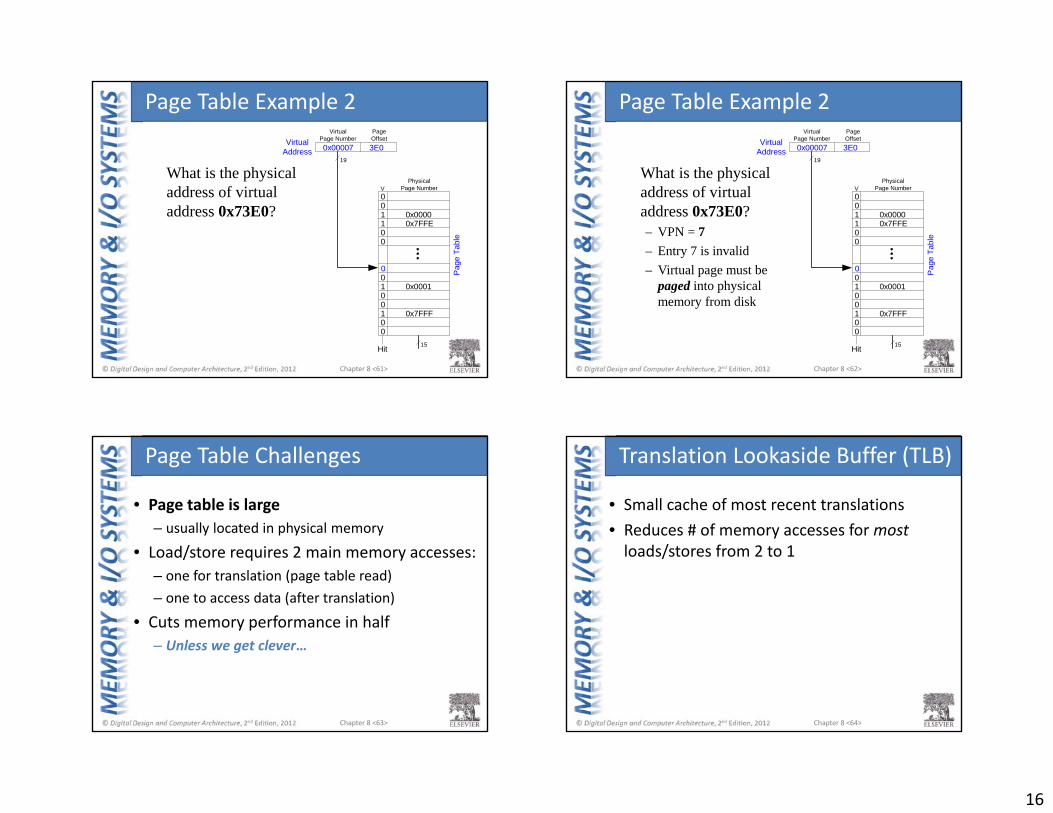
What is the physical address of virtual address 0x73E0?
Page Table Example 2
Chapter 8 <62>
001 0x00001 0x7FFE00
001 0x0001001 0x7FFF00
V
VirtualAddress 0x00007 3E0
Hit
PhysicalPage Number
19
15
VirtualPage Number
Pag
e Ta
ble
PageOffset
What is the physical address of virtual address 0x73E0?– VPN = 7– Entry 7 is invalid– Virtual page must be
paged into physical memory from disk
Page Table Example 2
Chapter 8 <63>
• Page table is large– usually located in physical memory
• Load/store requires 2 main memory accesses:– one for translation (page table read)– one to access data (after translation)
• Cuts memory performance in half– Unless we get clever…
Page Table Challenges
Chapter 8 <64>
• Small cache of most recent translations• Reduces # of memory accesses for mostloads/stores from 2 to 1
Translation Lookaside Buffer (TLB)
17
Chapter 8 <65>
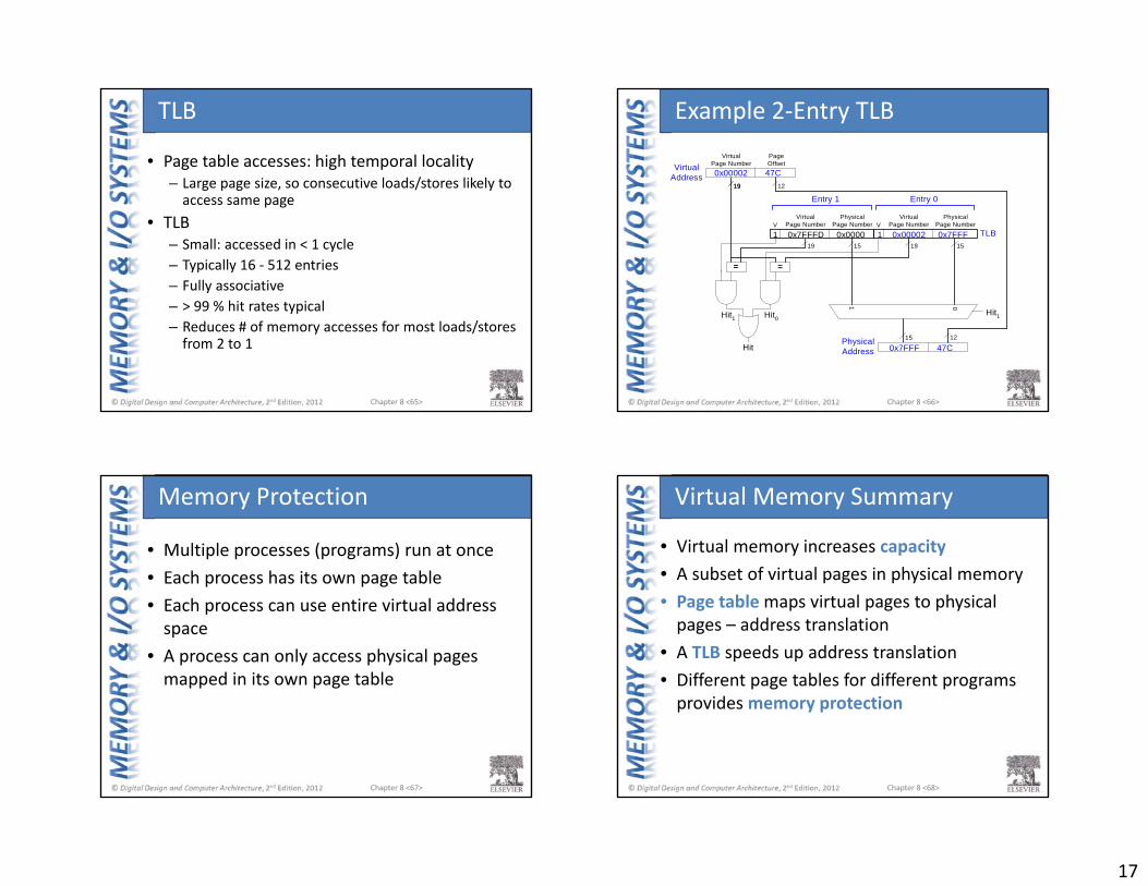
• Page table accesses: high temporal locality– Large page size, so consecutive loads/stores likely to access same page
• TLB– Small: accessed in < 1 cycle– Typically 16 ‐ 512 entries– Fully associative– > 99 % hit rates typical– Reduces # of memory accesses for most loads/stores from 2 to 1
TLB
Chapter 8 <66>
Hit1
V
=
01
15 15
15
=
Hit1Hit0
Hit
19 19
19
VirtualPage Number
PhysicalPage Number
Entry 1
1 0x7FFFD 0x0000 1 0x00002 0x7FFF
VirtualAddress 0x00002 47C
1219
VirtualPage Number
PageOffset
VVirtual
Page NumberPhysical
Page Number
Entry 0
12PhysicalAddress 0x7FFF 47C
TLB
Example 2‐Entry TLB
Chapter 8 <67>
• Multiple processes (programs) run at once• Each process has its own page table• Each process can use entire virtual address space
• A process can only access physical pages mapped in its own page table
Memory Protection
Chapter 8 <68>
• Virtual memory increases capacity• A subset of virtual pages in physical memory• Page tablemaps virtual pages to physical pages – address translation
• A TLB speeds up address translation• Different page tables for different programs provides memory protection
Virtual Memory Summary
18
Chapter 8 <69>
• Processor accesses I/O devices just like memory (like keyboards, monitors, printers)
• Each I/O device assigned one or more address
• When that address is detected, data read/written to I/O device instead of memory
• A portion of the address space dedicated to I/O devices
Memory‐Mapped I/O
Chapter 8 <70>
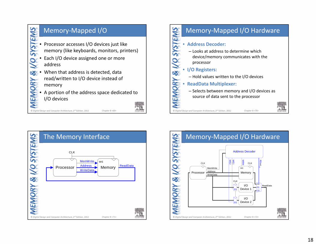
• Address Decoder:– Looks at address to determine which device/memory communicates with the processor
• I/O Registers:– Hold values written to the I/O devices
• ReadData Multiplexer:– Selects between memory and I/O devices as source of data sent to the processor
Memory‐Mapped I/O Hardware
Chapter 8 <71>
Processor MemoryAddressMemWrite
WriteDataReadData
WE
CLK
The Memory Interface
Chapter 8 <72>
Processor MemoryAddressMemWrite
WriteData
ReadDataI/ODevice 1
I/ODevice 2
CLK
EN
EN
Address Decoder
WE
WE
M
RD
sel1:0
WE
2W
E1 CLK
000110
CLK
Memory‐Mapped I/O Hardware
19
Chapter 8 <73>
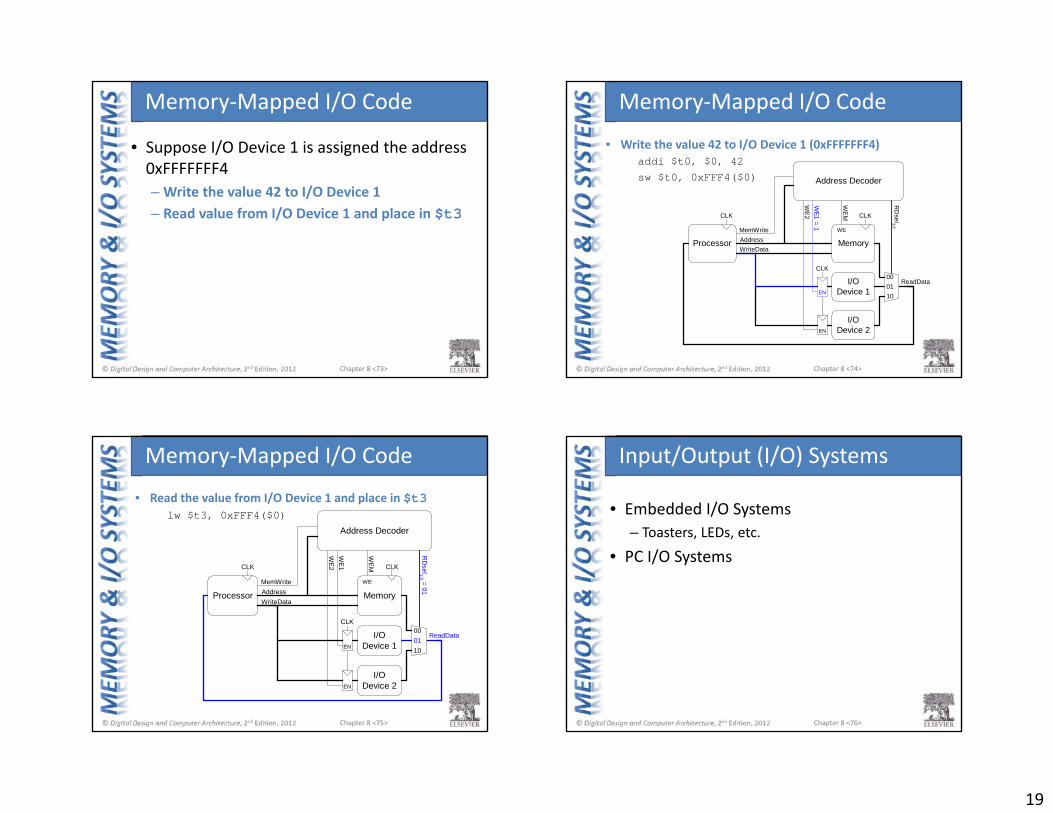
• Suppose I/O Device 1 is assigned the address 0xFFFFFFF4– Write the value 42 to I/O Device 1– Read value from I/O Device 1 and place in $t3
Memory‐Mapped I/O Code
Chapter 8 <74>
• Write the value 42 to I/O Device 1 (0xFFFFFFF4)addi $t0, $0, 42
sw $t0, 0xFFF4($0)
Processor MemoryAddressMemWrite
WriteData
ReadDataI/ODevice 1
I/ODevice 2
CLK
EN
EN
Address Decoder
WE
WE
M
RD
sel1:0
WE
2W
E1 = 1
CLK
000110
CLK
Memory‐Mapped I/O Code
Chapter 8 <75>
• Read the value from I/O Device 1 and place in $t3lw $t3, 0xFFF4($0)
Processor MemoryAddressMemWrite
WriteData
ReadDataI/ODevice 1
I/ODevice 2
CLK
EN
EN
Address Decoder
WE
WE
M
RD
sel1:0 = 01
WE
2W
E1 CLK
000110
CLK
Memory‐Mapped I/O Code
Chapter 8 <76>
• Embedded I/O Systems– Toasters, LEDs, etc.
• PC I/O Systems
Input/Output (I/O) Systems

20
Chapter 8 <77>
• Example microcontroller: PIC32– microcontroller– 32‐bit MIPS processor– low‐level peripherals include:
• serial ports• timers• A/D converters
Embedded I/O Systems
Chapter 8 <78>
// C Code
#include <p3xxxx.h>
int main(void) {
int switches;
TRISD = 0xFF00; // RD[7:0] outputs
// RD[11:8] inputs
while (1) {
// read & mask switches, RD[11:8]
switches = (PORTD >> 8) & 0xF;
PORTD = switches; // display on LEDs
}
}
Digital I/O
RD0 46
RD1 49
RD2 50
RD3 51
RD4 52
RD5 53
RD6 54
RD7 55
RD8 42
RD9 43
RD10 44
RD11 45
PIC
32
LEDs
3.3 V
R=
1K
Ω
R=
330Ω
Switches
Chapter 8 <79>
• Example serial protocols– SPI: Serial Peripheral Interface– UART: Universal Asynchronous Receiver/Transmitter
– Also: I2C, USB, Ethernet, etc.
Serial I/O
Chapter 8 <80>
SPI: Serial Peripheral Interface
SCK
SDO
SDI
SCK
SDI
SDO
Master Slave
(a)
(b)
SCK
SDO
SDI
bit 7 bit 6 bit 5 bit 4 bit 3 bit 2 bit 1 bit 0
bit 7 bit 6 bit 5 bit 4 bit 3 bit 2 bit 1 bit 0
• Master initiates communication to slave by sending pulses on SCK
• Master sends SDO (Serial Data Out) to slave, msb first• Slave may send data (SDI) to master, msb first

21
Chapter 8 <81>
UART: Universal Asynchronous Rx/Tx
TX
RX
DTE
TX
RX
DCE(a)
(b)Idle Start Stopbit 0 bit 1 bit 2 bit 3 bit 4 bit 5 bit 6 bit 7
1/9600 sec
• Configuration:– start bit (0), 7‐8 data bits, parity bit (optional), 1+ stop bits (1)– data rate: 300, 1200, 2400, 9600, …115200 baud
• Line idles HIGH (1)• Common configuration:
– 8 data bits, no parity, 1 stop bit, 9600 baud
Chapter 8 <82>
// Create specified ms/us of delay using built-in timer#include <P32xxxx.h>
void delaymicros(int micros) {if (micros > 1000) { // avoid timer overflow
delaymicros(1000); delaymicros(micros-1000);
} else if (micros > 6){
TMR1 = 0; // reset timer to 0 T1CONbits.ON = 1; // turn timer onPR1 = (micros-6)*20; // 20 clocks per microsecond
// Function has overhead of ~6 us IFS0bits.T1IF = 0; // clear overflow flagwhile (!IFS0bits.T1IF); // wait until overflow flag set
}}
void delaymillis(int millis) {while (millis--) delaymicros(1000); // repeatedly delay 1 ms
} // until done
Timers
Chapter 8 <83>
• Needed to interface with outside world• Analog input: Analog‐to‐digital (A/D) conversion
– Often included in microcontroller– N‐bit: converts analog input from Vref‐‐Vref+ to 0‐2N‐1
• Analog output:– Digital‐to‐analog (D/A) conversion
• Typically need external chip (e.g., AD558 or LTC1257)• N‐bit: converts digital signal from 0‐2N‐1 to Vref‐‐Vref+
– Pulse‐width modulation
Analog I/O
Chapter 8 <84>
Pulse‐Width Modulation (PWM)
Period
Pulse width Duty cycle = Pulse width
Period
OC1/RD0 46
PIC
1 KΩ
0.1 μF
Vout
• Average value proportional to duty cycle
• Add high‐pass filter on output to deliver average value
22
Chapter 8 <85>
Other Microcontroller Peripherals
• Examples– Character LCD– VGA monitor– Bluetooth wireless– Motors
Chapter 8 <86>
Personal Computer (PC) I/O Systems
• USB: Universal Serial Bus– USB 1.0 released in 1996– standardized cables/software for peripherals
• PCI/PCIe: Peripheral Component Interconnect/PCI Express– developed by Intel, widespread around 1994– 32‐bit parallel bus– used for expansion cards (i.e., sound cards, video cards, etc.)
• DDR: double‐data rate memory
Chapter 8 <87>
Personal Computer (PC) I/O Systems
• TCP/IP: Transmission Control Protocol and Internet Protocol– physical connection: Ethernet cable or Wi‐Fi
• SATA: hard drive interface• Input/Output (sensors, actuators, microcontrollers, etc.)– Data Acquisition Systems (DAQs) – USB Links