processing shale feedstocks - digitalrefining · 3225 gallows road, fairfax, ... recent transaction...
TRANSCRIPT
processing shale feedstocks
2013
PTQ supplement
gas to petrochemicals special
gas cov copy 5.indd 1 28/02/2013 14:22

Imagine the
of forcing flames downward...
...against the natural buoyancy of the flue gases. Our steam methanereformer design fires upward, reducing fan power consumption by
40 - 50%, to save operating costs.
Choose the Foster Wheeler Terrace Wall™ Steam Reformer for your hydrogen plant.
ineff ciency
Learn more at www.fwc.com/terracewall
fw.indd 1 25/02/2013 15:00
©2013. The entire content of this publication is protected by copyright full details of which are available from the publishers. All rights reserved. No part of this publication may be reproduced, stored in a retrieval system or transmitted in any form or by any means – electronic, mechanical, photocopying, recording or otherwise – without the prior permission of the copyright owner.The opinions and views expressed by the authors in this publication are not necessarily those of the editor or publisher and while every care has been taken in the preparation of all material included in Petroleum Technology Quarterly the publisher cannot be held responsible for any statements, opinions or views or for any inaccuracies.
3 Weighing in on shale gas to petrochemicals RenéGonzalez 5 Roundtable ptq&a11 Processing Trends17 Shale gas feeds petrochemical expansion RenéGonzalez 17 Driving down costs in hydrogen production LuigiBressanandChrisDavis Foster Wheeler 29 Cracking hydrocarbon feedstock with a heavy tail JohanvanderEijk Technip
33 Naphtha catalytic cracking for propylene production ChristopherDean High Olefins FCC Technology Services
39 Maximise ethylene gain and acetylene selective hydrogenation efficiency LingXu,WolfSpaether,MingyongSun,JenniferBoyer andMichaelUrbancic Clariant
45 Reducing emission treatment costs for gas processors KevinSumm Anguil Environmental Systems
SasolFTWaxExpansionProject,Sasolburg,SouthAfrica:FosterWheeleristheengineering,procurementandconstructionmanagementcontractor,oneofthelargestSasolprojectsunderwayanywhereintheworld. Published by kind permission of Sasol. Image: Courtesy of Deryck Coetzer, Sasol
2013www.eptq.com
Processing shale feedstocks
gas to petrochemicalsspecial
ed com.indd 1 28/02/2013 14:25
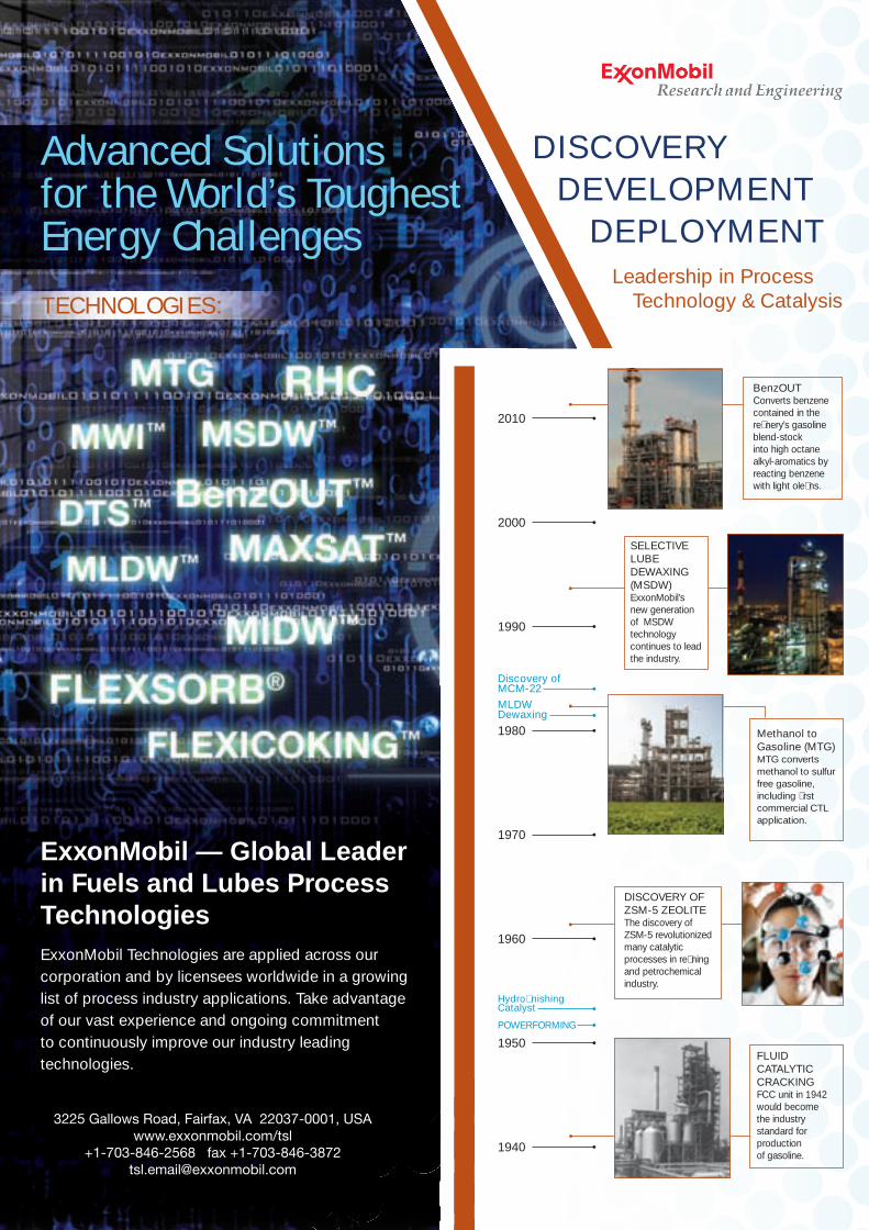
ExxonMobil — Global Leader in Fuels and Lubes Process TechnologiesExxonMobil Technologies are applied across our corporation and by licensees worldwide in a growing list of process industry applications. Take advantage of our vast experience and ongoing commitment to continuously improve our industry leading technologies.
TECHNOLOGIES :
3225 Gallows Road, Fairfax, VA 22037-0001, USAwww.exxonmobil.com/tsl
+1-703-846-2568 fax [email protected]
Advanced Solutions for the World’s Toughest Energy Challenges
Leadership in Process Technology & Catalysis
developmentdeployment
discovery
2010
2000
1990
1980
1970
1960
1950
1940
SELECTIVE LUBE DEWAXING (MSDW)ExxonMobil’s new generation of MSDW technology continues to lead the industry.
Methanol to Gasoline (MTG)MTG converts methanol to sulfur free gasoline, including first commercial CTL application.
FLUID CATALYTIC CRACKINGFCC unit in 1942 would become the industry standard for production of gasoline.
BenzOUT Converts benzene contained in the refinery’s gasoline blend-stock into high octane alkyl-aromatics by reacting benzene with light olefins.
DISCOVERY OF ZSM-5 ZEOLITEThe discovery of ZSM-5 revolutionized many catalytic processes in refining and petrochemical industry.
pOWERFORMING
HydrofinishingCatalyst
MLDWDewaxing
Discovery of MCM-22
exxon.indd 1 28/02/2013 14:28
The European Union has arguably been the global leader in biodiesel production and use, with overall
biodiesel production increasing from 1.9 million tonnes in 2004 to nearly 10.3 million tonnes in 2007. Biodiesel production in the US has also increased dramatically in the past few years from 2 million gallons in 2000 to approximately 450 million gallons in 2007. According to the National Biodiesel Board, 171 companies own biodiesel manufacturing plants and are actively marketing biodiesel.1. The global biodiesel market is estimated to reach 37 billion gallons by 2016, with an average annual growth rate of 42%. Europe will continue to be the major biodiesel market for the next decade, followed closely by the US market.
Although high energy prices, increasing global demand, drought and other factors are the primary drivers for higher food prices, food competitive feedstocks have long been and will continue to be a major concern for the development of biofu-els. To compete, the industry has responded by developing methods to increase process efficiency, utilise or upgrade by-products and operate with lower quality lipids as feedstocks.
Feedstocks
Biodiesel refers to a diesel-equivalent fuel consisting of short-chain alkyl (methyl or ethyl) esters, made by the transesterification of triglycerides, commonly known as vegetable oils or animal fats. The most common form uses methanol, the cheapest alcohol available, to produce methyl esters. The molecules in biodiesel are pri-marily fatty acid methyl esters (FAME), usually created by trans-esterification between fats and metha-nol. Currently, biodiesel is produced from various vegetable and plant oils. First-generation food-based feedstocks are straight vegetable oils such as soybean oil and animal fats such as tallow, lard, yellow grease, chicken fat and the by-products of the production of Omega-3 fatty acids from fish oil. Soybean oil and rapeseeds oil are the common source for biodiesel produc-tion in the US and Europe in quanti-ties that can produce enough biodie-sel to be used in a commercial market with currently applicable
Processing Shale Feedstocks 2013 3
Project Editor René [email protected]
Production EditorRachel [email protected]
Graphics EditorRob Fris [email protected]
Editorial tel +44 844 5888 773fax +44 844 5888 667
Business Development DirectorPaul [email protected] Advertising SalesBob [email protected]
Advertising Sales Officetel +44 844 5888 771 fax +44 844 5888 662
PublisherNic [email protected]
CirculationJacki [email protected]
Crambeth Allen Publishing LtdHopesay, Craven Arms SY7 8HD, UKtel +44 844 5888 776fax +44 844 5888 667
ptq (petroleum technology quarterly) (ISSN No: 1632-363X, USPS No: 014-781) is published quarterly plus annual Catalysis edition by Crambeth Allen Publishing Ltd and is distributed in the US by SP/Asendia, 17B South Middlesex Avenue, Monroe NJ 08831. Periodicals postage paid at New Brunswick, NJ. Postmaster: send address changes to ptq (petroleum technology quarterly), 17B South Middlesex Avenue, Monroe NJ 08831.Back numbers available from the Publisher at $30 per copy inc postage.
Vol 18 No 3
2013
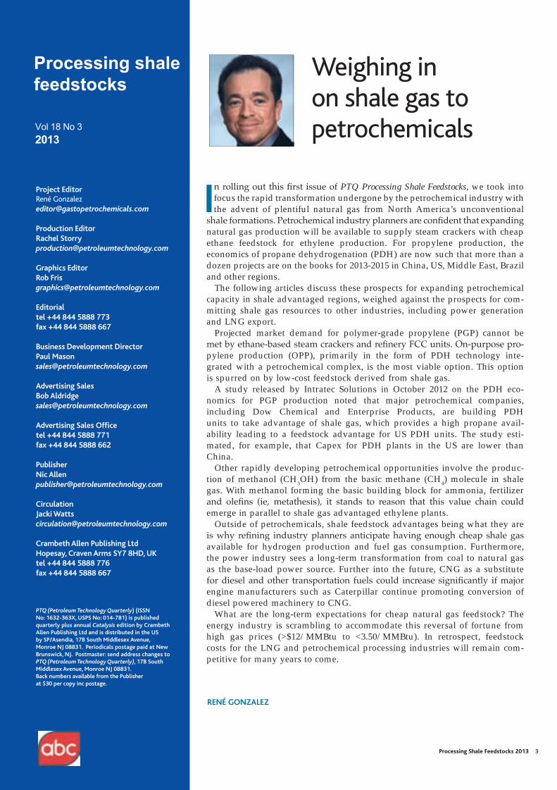
Weighing in on shale gas to petrochemicals
In rolling out this first issue of PTQ Processing Shale Feedstocks, we took into focus the rapid transformation undergone by the petrochemical industry with the advent of plentiful natural gas from North America’s unconventional
shale formations. Petrochemical industry planners are confident that expanding natural gas production will be available to supply steam crackers with cheap ethane feedstock for ethylene production. For propylene production, the economics of propane dehydrogenation (PDH) are now such that more than a dozen projects are on the books for 2013-2015 in China, US, Middle East, Brazil and other regions.
The following articles discuss these prospects for expanding petrochemical capacity in shale advantaged regions, weighed against the prospects for com-mitting shale gas resources to other industries, including power generation and LNG export.
Projected market demand for polymer-grade propylene (PGP) cannot be met by ethane-based steam crackers and refinery FCC units. On-purpose pro-pylene production (OPP), primarily in the form of PDH technology inte-grated with a petrochemical complex, is the most viable option. This option is spurred on by low-cost feedstock derived from shale gas.
A study released by Intratec Solutions in October 2012 on the PDH eco-nomics for PGP production noted that major petrochemical companies, including Dow Chemical and Enterprise Products, are building PDH units to take advantage of shale gas, which provides a high propane avail-ability leading to a feedstock advantage for US PDH units. The study esti-mated, for example, that Capex for PDH plants in the US are lower than China.
Other rapidly developing petrochemical opportunities involve the produc-tion of methanol (CH3OH) from the basic methane (CH4) molecule in shale gas. With methanol forming the basic building block for ammonia, fertilizer and olefins (ie, metathesis), it stands to reason that this value chain could emerge in parallel to shale gas advantaged ethylene plants.
Outside of petrochemicals, shale feedstock advantages being what they are is why refining industry planners anticipate having enough cheap shale gas available for hydrogen production and fuel gas consumption. Furthermore, the power industry sees a long-term transformation from coal to natural gas as the base-load power source. Further into the future, CNG as a substitute for diesel and other transportation fuels could increase significantly if major engine manufacturers such as Caterpillar continue promoting conversion of diesel powered machinery to CNG.
What are the long-term expectations for cheap natural gas feedstock? The energy industry is scrambling to accommodate this reversal of fortune from high gas prices (>$12/MMBtu to <3.50/MMBtu). In retrospect, feedstock costs for the LNG and petrochemical processing industries will remain com-petitive for many years to come.
RENé GONzALEz
Processing shale feedstocks
ed com.indd 2 25/02/2013 17:03

Q What opportunities are available for shale midstream processors going forward from 2013?
A Joshua Hallenbeck, Vice President, MarkWest Energy PartnersAs drillers (for example, Gulfport Energy) begin sell-ing methane, propane, butane, pentane and oil, such as from the 28.5 mcfd of natural gas now being produced from the Shugert 1 well in a section of the state of Ohio’s Utica Shale play known as Egypt Valley in Belmont County, Mark West Energy is now processing Gulfport gas from the first phase of its processing complex near Cadiz.
Gulfport’s success in the Utica Shale and the commencement of operations at our Cadiz Complex are significant accomplishments in the ongoing Utica Shale development in Eastern Ohio. Early results indi-cate this play is one of the most exciting new areas for natural gas and liquids production in the US — and given our leading position in the neighbouring Marcellus Shale, we are well positioned to support producers’ future development plans in the Utica.
In natural gas processing, the dry methane part of the gas stream is separated from the wet portions —ethane, butane, propane and pentane. During fractionation, the natural gas liquids and other substances are separated from each other. These sepa-rated gas products are then ready for use, with the ethane possibly going to a cracker plant somewhere in North America. MarkWest plans to send ethane from Cadiz to Gulf Coast markets for cracking there.
A Wouter van Kempen, President and CEO, DCP MidstreamThe DCP Midstream enterprise continues to execute on its slate of growth projects underpinned by solid contracts in liquids-rich areas. We process 6.3 trillion Btu of gas everyday and our NGL production is well over 400 000 bpd. Back in early December 2012, DCP Midstream and DCP Midstream Partners announced the construction of a new cryogenic plant that will serve the growing demand from producers in the liquids-rich Eagle Ford shale in Texas. The new Goliad plant (located near Goliad, Texas) will be constructed
and funded by the previously announced DCP Eagle Ford joint venture, which is owned two-thirds by DCP Midstream and one-third by DCP Midstream Partners.
The Goliad cryogenic plant will have a gas process-ing capacity of 200 million cfd and will become part of the DCP Eagle Ford system, providing Eagle Ford producers a one-stop service from the plant tailgate to Gulf Coast market centres. The Goliad plant is expected to be completed by Q1 2014. Through co- investment with DCP Midstream Partners and the recent transaction on the pipelines with Phillips 66 and Spectra Energy, we can continue to fund our proj-ects and create value for all our stakeholders. The Goliad plant is the seventh plant in South Texas owned by the DCP enterprise.
Q Based on your coverage of the US East Coast shale industry, can you comment on progress in the construction of ethane-based steam crackers for ethylene production?
A Julio Renteria, Business Development Manager, CatecA recent ICIS News report noted that the lack of infrastructure for Shell’s proposed western Pennsylvania cracker provides an opportunity for
www.eptq.com Processing Shale Feedstocks 2013 5
Roundtable ptq&a
Additional Q&A can be found at www.eptq.com/QandA
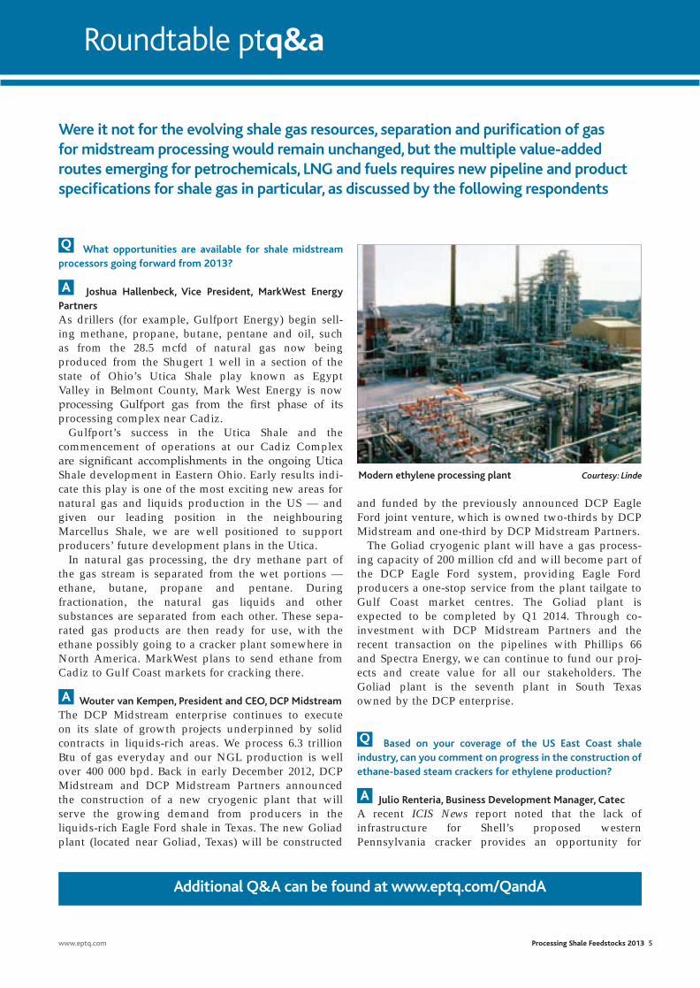
Modern ethylene processing plant Courtesy: Linde
Were it not for the evolving shale gas resources, separation and purification of gas for midstream processing would remain unchanged, but the multiple value-added routes emerging for petrochemicals, LNG and fuels requires new pipeline and product specifications for shale gas in particular, as discussed by the following respondents
Q&A copy 12.indd 1 25/02/2013 17:06
Nova Chemicals to expand its Corunna ethylene facil-ity and displace Shell’s ethane supply. According to Peter Voser, the Shell Chemicals CEO, Shell could have a cracker completed by 2017 if it began construc-tion in 2014. There are no ethane cracker plants in the Marcellus region at the present time, although Aither Chemicals, an upstart company touting an untried catalytic cracking approach, is promoting a plant near Charleston, West Virginia. Surplus ethane from the so-called “wet natural gas” of western Pennsylvania and northern West Virginia is too valuable to burn
because it can be cracked into ethylene for the manu-facture of polyethylene and other products.
According to some experts in the industry, Nova would have a more reliable destination for ethane if it expanded its Corunna cracker capacities near Sarnia, Ontario, Canada. The expansion would require less money and less time than Shell’s project. A major expansion at Corunna could be completed years before Shell completes construction of a world-scale facility.
The Sarnia region has salt caverns to store hydrocar-bons and liquefied petrochemical feedstock such as ethane. Nova’s Corunna cracker in Sarnia already plans to use ethane from the Marcellus shale basin. An exist-ing Sunoco pipeline from the western Pennsylvania to
Sarnia will transport 40 000 bpd of ethane to Nova’s cracker, and an additional 10 000 bpd to the region for other plants. In addition, Nova will upgrade the feed-stock capability at the cracker by the end of 2013 to 100% of NGL feeds, company CEO Randy Woelfel said. Also, Imperial Oil has a refinery and petrochemical complex in Sarnia. The complex produces a wide range of products, including polyethylene, solvents, olefins and aromatics, the company said.
Q What is an important technical challenge to consider for new steam crackers coming online before 2017?
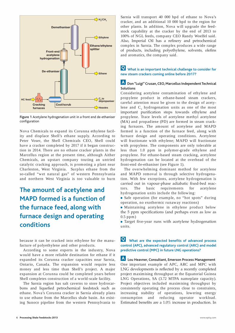
A Don “Luigi” Crusan, CEO, Marcellus Independent Technical SolutionsConsidering acetylene contamination of ethylene and propylene product in ethane-based steam crackers, careful attention must be given to the design of acety-lene and C3 hydrogenation units as one of the most important purification steps towards ethylene and propylene. Trace levels of acetylene methyl acetylene (MA) and propadiene (PD) are formed in steam crack-ing furnaces. The amount of acetylene and MAPD formed is a function of the furnace feed, along with furnace design and operating conditions. Acetylene will fractionate with ethylene; MAPD will fractionate with propylene. The components are only tolerable at less than 1.0 ppm in polymer-grade ethylene and propylene. For ethane-based steam cracking, acetylene hydrogenation can be located at the overhead of the front-end de-ethaniser (see Figure 1).
The overwhelming dominant method for acetylene and MAPD removal is through selective hydrogena-tion. With few exceptions, acetylene hydrogenation is carried out in vapour-phase adiabatic fixed-bed reac-tors. The basic requirements for acetylene hydrogenation units include the following:• Safe operation (for example, no “hot spots” during operation, no exothermic runaway reactions)• Maintaining acetylene in ethylene product below the 5 ppm specifications (and perhaps even as low as 0.5 ppm)• Target five-year runs with acetylene hydrogenation units.
Q What are the expected benefits of advanced process control (APC), advanced regulatory control (ARC) and model predictive control (MPC) in future LNG operations?
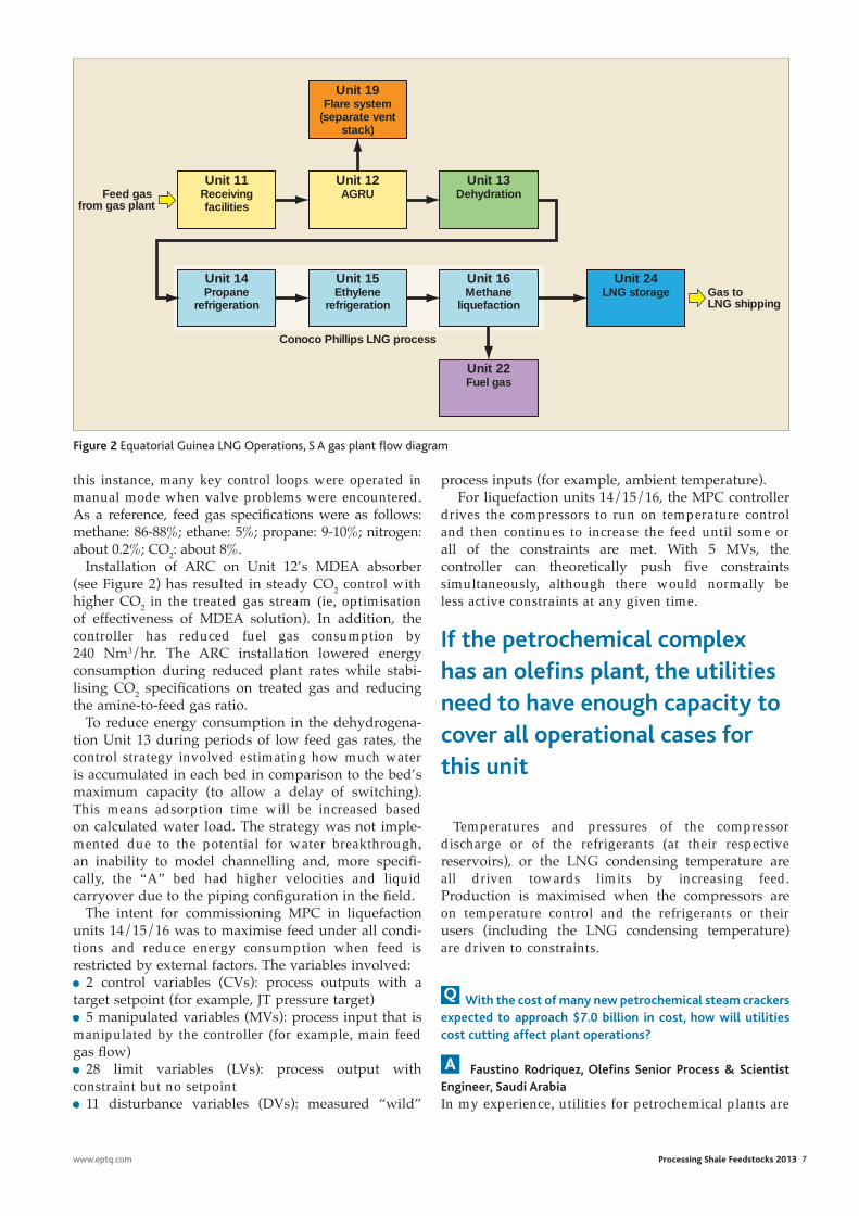
A Lou Heavner, Consultant, Emerson Process ManagementOne important example of APC, ARC and MPC with LNG developments is reflected by a recently completed project maximising throughput at the Equatorial Guinea LNG Operations, SA (3.72 MTPA nameplate capacity). Project objectives included maximising throughput by consistently operating the process close to constraints, increasing stability of operations, lowering energy consumption and reducing operator workload. Estimated benefits are a 1.0% increase in production. In
6 Processing Shale Feedstocks 2013 www.eptq.com
HC feed
Demethaniser
Ethane/ethylene splitter
Front-end acetylene
hydrogenation
De-ethaniser
Cracking furnaces
Cool/scrub
H2/CH4
Ethylene
Ethane
C3 to depropaniser
Heavies
Figure 1 Acetylene hydrogenation unit in a front end de-ethaniser configuration
The amount of acetylene and MAPD formed is a function of the furnace feed, along with furnace design and operating conditions
Q&A copy 12.indd 2 25/02/2013 17:07
www.eptq.com Processing Shale Feedstocks 2013 7
this instance, many key control loops were operated in manual mode when valve problems were encountered. As a reference, feed gas specifi cations were as follows: methane: 86-88%; ethane: 5%; propane: 9-10%; nitrogen: about 0.2%; CO2: about 8%.
Installation of ARC on Unit 12’s MDEA absorber (see Figure 2) has resulted in steady CO2 control with higher CO2 in the treated gas stream (ie, optimisation of effectiveness of MDEA solution). In addition, the controller has reduced fuel gas consumption by 240 Nm3/hr. The ARC installation lowered energy consumption during reduced plant rates while stabi-lising CO2 specifi cations on treated gas and reducing the amine-to-feed gas ratio.
To reduce energy consumption in the dehydrogena-tion Unit 13 during periods of low feed gas rates, the control strategy involved estimating how much water is accumulated in each bed in comparison to the bed’s maximum capacity (to allow a delay of switching). This means adsorption time will be increased based on calculated water load. The strategy was not imple-mented due to the potential for water breakthrough, an inability to model channelling and, more specifi -cally, the “A” bed had higher velocities and liquid carryover due to the piping confi guration in the fi eld.
The intent for commissioning MPC in liquefaction units 14/15/16 was to maximise feed under all condi-tions and reduce energy consumption when feed is restricted by external factors. The variables involved:• 2 control variables (CVs): process outputs with a target setpoint (for example, JT pressure target)• 5 manipulated variables (MVs): process input that is manipulated by the controller (for example, main feed gas fl ow)• 28 limit variables (LVs): process output with constraint but no setpoint• 11 disturbance variables (DVs): measured “wild”
process inputs (for example, ambient temperature). For liquefaction units 14/15/16, the MPC controller
drives the compressors to run on temperature control and then continues to increase the feed until some or all of the constraints are met. With 5 MVs, the controller can theoretically push fi ve constraints simultaneously, although there would normally be less active constraints at any given time.
Temperatures and pressures of the compressor discharge or of the refrigerants (at their respective reservoirs), or the LNG condensing temperature are all driven towards limits by increasing feed. Production is maximised when the compressors are on temperature control and the refrigerants or their users (including the LNG condensing temperature) are driven to constraints.
Q With the cost of many new petrochemical steam crackers expected to approach $7.0 billion in cost, how will utilities cost cutting affect plant operations?
A Faustino Rodriquez, Olefi ns Senior Process & Scientist Engineer, Saudi ArabiaIn my experience, utilities for petrochemical plants are
Unit 19Flare system
(separate vent stack)
Unit 11Receiving facilities
Unit 12AGRU
Unit 14Propane
refrigeration
Unit 15Ethylene
refrigeration
Unit 16Methane
liquefaction
Unit 24LNG storage
Unit 22Fuel gas
Unit 13Dehydration
Conoco Phillips LNG process
Gas to LNG shipping
Feed gas from gas plant
Figure 2 Equatorial Guinea LNG Operations, S A gas plant fl ow diagram
If the petrochemical complex has an olefi ns plant, the utilities need to have enough capacity to cover all operational cases for this unit
Q&A copy 12.indd 3 26/02/2013 11:21
plant are extremely small on a per-pound basis. Multiple, smaller US ethylene/polyethylene production facilities can support desired social objec-tives (more real jobs and a pool of experienced people).
In addition, there are four propane dehydrogena-tion (PDH) projects being seriously discussed, or moving forward, in North America. Interestingly, there are also new technologies ready for commercial-isation for the conversion of natural gas to propylene. One such new technology is bromine based and offered by GRT, Inc. The new technologies cite lower capital costs.
The current interest in PDH is based on the rapid switch to ethane as the feedstock of preference for ethylene production. For all practical purposes, no co-product propylene is produced when ethane is cracked (3% propylene yield for ethane, versus 18% for propane and 13% for naphtha). A factor that has to be considered when looking at new PDH facilities is what to do with the propylene. For some applications, polyethylene competes directly with polypropylene on a price basis. In the Pacific, if the price of propane is detached from crude prices, we will see propane replacing naphtha as a cracker feedstock. What I am suggesting is that the market leads, and a stampede to new PDH facilities could result in return on invest-ment (ROI) problems.
Q Can you elaborate why managing audits in the upstream drilling business has taken on such an urgency for the shale gas industry?
A Kevin Koser, President, ExaserveThere have been many changes with regards to company commitment and the vision of audits during and after projects. The urgency, I believe, has been driven because of the collision of two market shifts. First is the strict adherence to legal compliance and the focus on maintaining integrity throughout all company decisions and processes. This, of course, really ramped up when companies were introduced to heavier regulations (such as Sarbanes-Oxley) than they were used to in the past. Second is a series of very public projects that have either gone millions in excess over budget or failed outright, both of which have been highlighted by very public legal actions. Executives have made it a priority to have indepen-dent audit teams investigate a project’s governance to insure all legal agreements have been met and that both client and partner have delivered everything promised.
The solutions that Exaserv has implemented for drillers can be used by any and all companies that wish to streamline processes, insure both data integ-rity and consistency, and manage all aspects of their employee population for both current and future growth. This SAP solution, designed and built by Exaserv, is available to any small to mid-sized operator.
8 Processing Shale Feedstocks 2013 www.eptq.com
always short. The problem starts during the design basis. You must consider the start-up periods of the units and upset conditions. The requirements of utili-ties are totally different from normal operation to trip condition. If the petrochemical complex has an olefins plant, the utilities need to have enough capacity to cover all operational cases for this unit.
From a maintenance point of view, you should consider spare capacity for preventive maintenance and major turnarounds. Normally, utilities must be available 100% of the time. So, high reliability consid-erations are required. In my experience, reducing costs in the project phase never covers loss of production because utilities are short in the future during the operational phase.
It is very difficult to indicate a margin of design for utilities in a petrochemical complex. Every utility needs to be analysed separately, considering many cases of operation. But consider a least 25% over- capacity over the worst case requirement. The worst case is peak demand during upsets or unit start-up. Be very careful in defining capacities and over-design for flare systems, incinerator and wastewater treatment systems.
Q There has been a lot of focus on new world-scale ethane-based ethylene plants and propane dehydrogenation (PDH) units coming online in the US by 2017. Do you see other alternatives to these high capital projects?
A James Cutler, CEO, Appalachian ResinsAppalachian Resins has received some very favour-able response to its business model and development efforts. There certainly are situations in which “world-scale” ethane-based ethylene plants are the way to go. No question about it. Alternatively, smaller plants, sized to reflect local markets, also have a place.
Development economics can dictate that a plant less than world scale is desirable. These factors can reflect environmental considerations, ability to dispose of ethane during periods of ethylene plant downtime and a wide array of required supporting off-sites. Another recently observed factor is that restart-up time due to power failures can be significant for world-scale ethylene plants.
The bottom line, in today’s world — resiliency due to facility redundancy — is an important consider-ation. Labour savings due to having a larger ethylene
The current interest in propane dehydrogenation is based on the rapid switch to ethane as the feedstock of preference for ethylene production
Q&A copy 12.indd 4 25/02/2013 17:07
Reliable SwiSS Quality
API 618Rod load up to 1'500 kN/335'000 IbsPower up to 31'000 kW/42'100 HP
Full Range:
You get moRe than Just aPRocess gas comPRessoR
Lubricated up to 1'000 bar, non-lubricated up to 300 bar
For highest availability: We recom-mend our own designed, in-house engineered compressor valves and key compressor components
Designed for easy maintenance
We are the competent partner with the full range of services – worldwide
→ www.recip.com/api618
Reliable SwiSS Quality
API 618Rod load up to 1'500 kN/335'000 IbsPower up to 31'000 kW/42'100 HP
Full Range:
You get moRe than Just aPRocess gas comPRessoR
Lubricated up to 1'000 bar, non-
For highest availability: We recom-mend our own designed, in-house engineered compressor valves and key compressor components
Designed for easy maintenance
We are the competent partner with the full range of services – worldwide
YouR BeneFit:lowest liFe cYcle costs
burckhardt.indd 1 7/3/12 21:39:05
1207
_e
www.airliquide.com
Because our genes lead us to an irrepressible passion for new solutions.
The only thing longer than our company historyis the list of our innovations.
When it comes to providing innovative plant and system solutions, Air Liquide Global E&C Solutions is your partner of choice – worldwide. No surprise, since we innovate relentlessly in order to bring sustainable and cost-eff ective solutions
to society, levera ging partnerships with customers, suppliers, academics and communities. This is not only demonstrated by thousands of patents, but by pionee-ring reference projects around the globe as well. Yours could be the next one.
AIR2185025_AZ_TechnoDNA_10/12_RZ.indd 1 16.10.12 14:18air liquide.indd 1 25/02/2013 17:05
New gas-to-petrochemical infrastructures require higher environmental compliance A growing percentage of ethane feedstock planned for new ethylene processing plants in North America are from unconventional gas resources. These unconven-tional gas resources are trapped in very tight or low permeability rock, and the effort required to extract them is greater than for conventional gas resources. This means higher intensity of drilling, entailing more industrial activity and disruption above ground. Producing gas from unconventional formations in many cases involves the use of hydraulic fracturing to boost the flow of gas from the well.
The potential environmental hazards and other features of unconventional gas development predicates higher investment in measuring, monitoring and controlling the potential environmental impact from the wellhead to the petrochemical processing facility. Starting at the wellhead, early and sustained engage-ment can reduce the above-ground impacts. This includes rigorous assessment, monitoring and handling of water resources for shale and tight gas.
Unconventional gas has higher production-related greenhouse gas emissions than conventional gas, but the difference can be reduced and the emissions of other pollutants lowered by eliminating venting and minimis-ing flaring during the well completion phase, similar in scope to reduced flaring seen in refinery and petrochem-ical process facilities. For example, releases of methane, wherever they occur in the gas supply chain serving the petrochemical end user, are particularly damaging, given methane’s potency as a greenhouse gas.
The main reason for the potentially larger environ-mental impact of unconventional gas operations is the nature of the resources themselves: unconventional resources are less concentrated than conventional deposits. They are more difficult to extract because they are trapped in very tight or low permeability rock that impedes flow. Since the resources are more diffuse and difficult to produce, the scale of the industrial operation required for a given volume of unconven-tional output is much larger than for conventional production. This means that drilling and production activities can be considerably more invasive, involving a generally larger environmental footprint.
Propylene production by dehydrogenation increases in importanceWith the ratio of propylene to ethylene expected to continue decreasing as a result of reduced naphtha-based steam cracking (while ethane-based
Reduce gasoline cutpoint
steam cracking from shale gas increases), propane dehydrogenation (PDH) to propylene will continue to expand in importance, as seen over the past two years in major petrochemical centres such as China. However, new PDH units are expected to be announced in North America and the Middle East too.
Of major importance to efficient PDH reactor design is the dehydrogenation catalyst. Recently, propane combined with selective hydrogen combustion over Pt-Sn bimetallic catalysts was discussed by Shinji Kaneko, et al, from the Department of Applied Chemistry, Saitama University in Saitama, Japan. Kaneko and colleagues noted that PDH has typically been carried out in the presence of inert gas, hydrogen or steam (normal dehydrogenation).
In the Kaneko study, dehydrogenation of propane combined with selective hydrogen combustion was studied over supported Pt-Sn bimetallic catalysts. A catalytic test for normal dehydrogenation was also carried out as part of the proposed process. Pt/Al2O3 modified with Sn and Zn was found to be suitable for both of these two reactions. In the normal dehydroge-nation, conversions equal to the calculated equilibrium conversion were achieved with almost complete selec-tivity for propylene. Optimisation of catalyst composition was done by the addition of various amounts of Sn to Pt/Al2O3 and Pt/Zn-Al-O. For dehy-drogenation combined with hydrogen combustion, selective hydrogen combustion was achieved over Pt-Sn bimetallic catalysts. Moreover, a stable conver-sion higher than that of equilibrium for normal dehydrogenation was obtained using Pt-Sn/Zn-Al-O under certain reaction conditions.
New technology makes small LNG facilities more competitive The Royal Dutch Shells Pearl gas-to-liquids (GTL) mega project at Ras Laffan in Qatar cost almost $20 billion. The facility delivered its first cargo of synthetic fuels in 2012 and, at full capacity, it will yield a quarter of Qatar’s entire oil output.
Halfway around the world, another mega project is taking shape. Shell has committed to building a float-ing liquefied natural gas (LNG) plant at its Prelude field off Western Australia. The plant, which will super-cool gas so it can be delivered worldwide by tanker, will be the largest floating structure ever built, six times as large as a Nimitz-class aircraft carrier. While this is a massive floating LNG plant, floating liquefaction plants may be scaled down and used to develop smaller or more remote fields where a land-
www.eptq.com Processing Shale Feedstocks 2013 11
Processing Trends
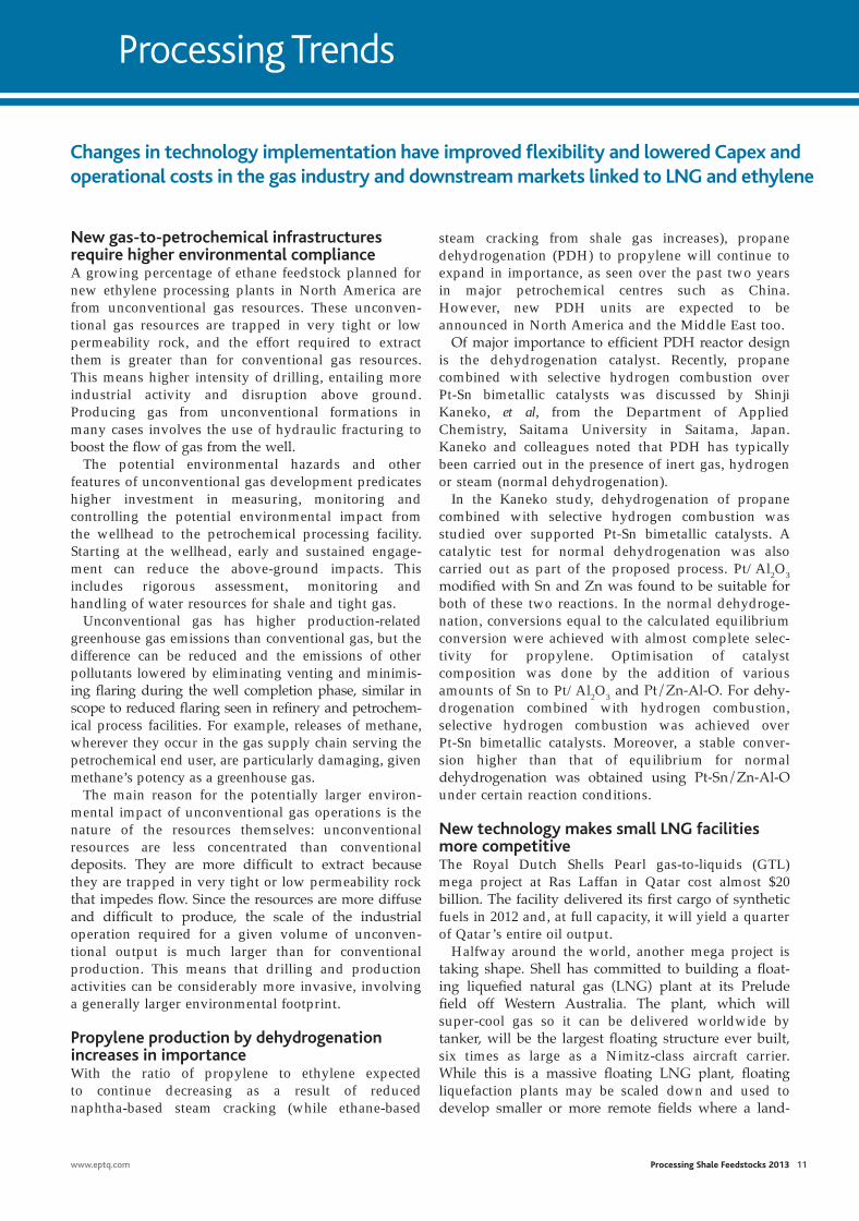
Changes in technology implementation have improved flexibility and lowered Capex and operational costs in the gas industry and downstream markets linked to LNG and ethylene
proc trends .indd 1 25/02/2013 19:22
diverge too widely between regions, and that buyers are not dependent on a single supplier.
To be sure, a key technical development in the LNG industry has been the evolution in the size of LNG trains over the past 25 years, resulting in significant unit cost reduction. Similar to liquefaction facilities, LNG ships have also been increasing in size to achieve reductions in the unit cost of LNG transported. Lessons learned in the design, execution and imple-mentation of large LNG trains and ships, as well as the overall changes in LNG liquefaction trains, has been key to the evolving design of the LNG value chain.
Nevertheless, the number of large discovered, unde-veloped gas resources needed to realise such economies of scale is decreasing. Continuous technol-ogy evolution will have to be maintained to enable economic utilisation of smaller, undeveloped, remote gas accumulations via concepts such as the previously noted floating liquefaction. The need to access markets in stricter permitting environments will drive innova-tion in terminals. In addition, an increasingly CO2-constrained regulatory environment will likely necessitate improved efficiencies and lower greenhouse gas emissions across the LNG value chain.
Low Capex LNG plants favoured for remote areasSmall and mid-scale LNG plants are used primarily to meet local or regional energy requirements, as noted by information available from Linde, which specialises in providing LNG plants. This means offering a full range of liquefaction technologies. Small to mid-scale LNG plants typically have a production capacity of 50 000– 3 000 000 tonnes per annum.
One reason LNG is gaining in importance through-out the world is because smaller LNG tankers and trucks can bring this fuel to regions that are not connected by natural gas pipelines. The distribution starting points are LNG terminals. In May 2011, the first of these small-scale LNG terminals went on stream outside Stockholm, Sweden, in the Baltic Sea region, engineered and operated by Linde Group
member AGA Gas AB. The facility is set to supply the eastern part of Sweden with LNG. Gothenburg-based cryogenic and storage specialists Cryo AB, also a member of The Linde Group, provided the complete storage tank facility, inclu-sive engineers, project management and construction.
To transport the LNG further, it is trans-ferred via a cryogenic system of pumps, pipes and tubes. The gas that evaporates during this process is recaptured by purpose-built re-liquefaction units. As a one-stop provider, Linde delivered all the components for the Nynäshamn terminal: from the LNG production plant in Stavanger to the storage tanks for trucks and ships, and from the on-site storage units to gasification facilities and systems to convert the LNG back into gas.
12 Processing Shale Feedstocks 2013 www.eptq.com
based facility would be too expensive, as noted in a report, The Gas Revolution is Here, by Dubai-based energy consultant, Robin Mills (www.natgas.info). Such floating LNG plants reduce onshore environmen-tal impact and disputes over land rights that hamper some projects.
In addition, floating LNG receiving terminals, which turn the liquefied cargoes back into gas for consumers to use, can be installed in months. Such terminals in Dubai and Kuwait have already started up since 2011, and their use is spreading through the world. Some countries are not sure about the quantity and timing of LNG they require, such as with the ongoing debate in the US concerning LNG exports from shale formations. For this type of scenario, a floating terminal, which can up anchors and move to a new destination, is ideal.
These innovations will support the transformation of the gas business as it continues its advance to being the fossil fuel of the future. Gas is suddenly in abun-dance while oil prices remain high. As a result, in the US, oil is more than four times as costly as the same energy from gas; even in Europe and Asia, the gap is two to one. In addition, gas-fired power stations are cleaner and quicker to build than coal, simpler and less controversial than nuclear power plants, and cheaper and more reliable than renewable power such as wind and solar. Gas is the fuel of choice for new electricity generation and is ideal for backing up variable renew-able energy. The volume of the international LNG trade has tripled over the past two decades, from 52 million tonnes per annum (MTA) in 1990 to 160 MTA in 2006. This growth is expected to continue over the next 20 years, resulting in a forecasted international LNG trade of 325 MTA by 2030.
In parallel, gas is increasingly replacing oil for elec-tricity and heating, and may also enter transport markets. Some ship owners, bound by stricter rules on using polluting refinery-based fuel oil, are considering LNG. As more LNG producers and more customers enter the fray, the market becomes increasingly flexible and liquid. This is essential to ensure that prices do not
NG
LNG
LPMR HPMR
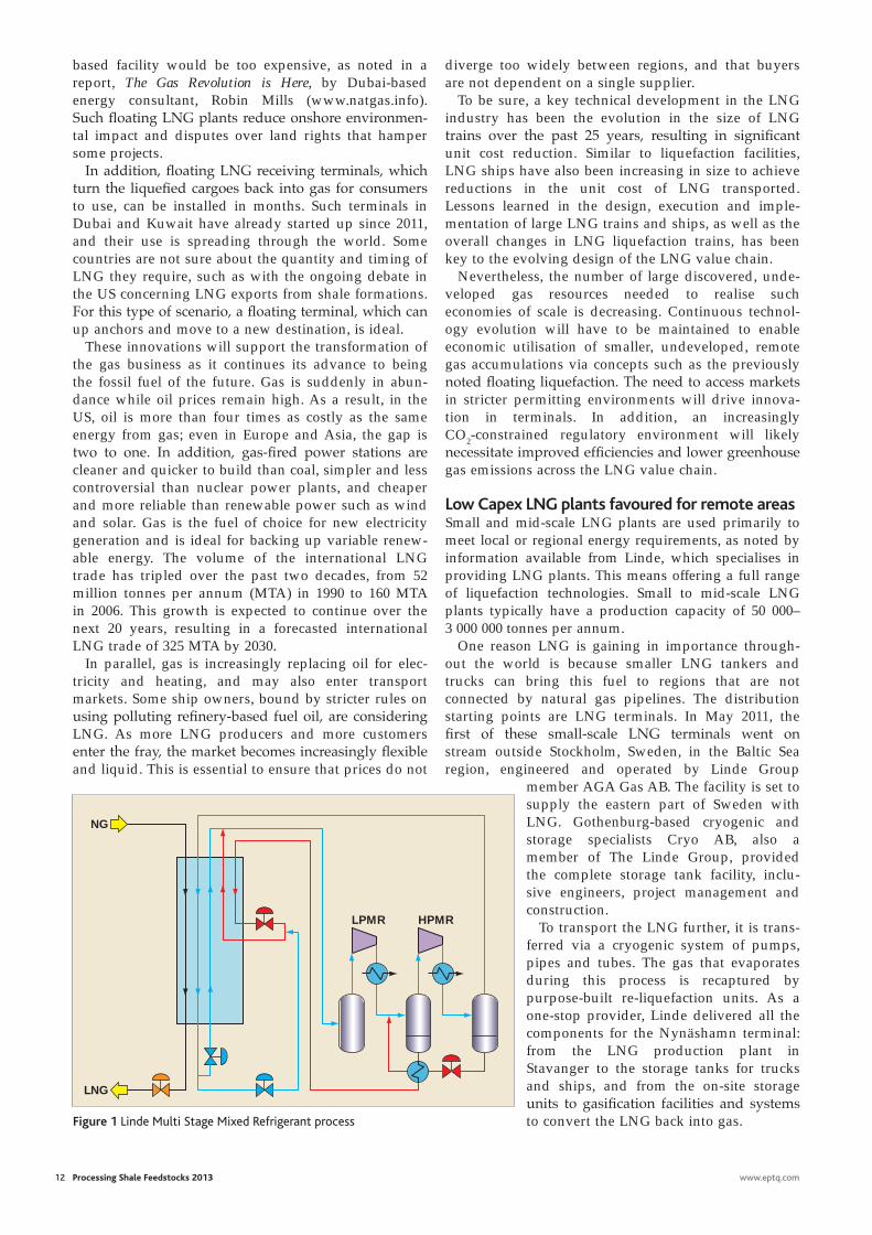
Figure 1 Linde Multi Stage Mixed Refrigerant process
proc trends .indd 2 26/02/2013 11:16

www.aveva.com/futureofplantdesign
AVEVA E3D is thE corE DEsign ApplicAtion within thE AVEVA plAnt proDuct portfolio. it is fully intEropErAblE with All othEr AVEVA EnginEEr, DEsign AnD MAnAgE proDucts.
AVEVA Everything3D plant Design for lean construction
AVEVA’s vision for the future of plant Design allows project teams to move up to a new level of performance for plant design and drives a new era of plant Design for lean construction. AVEVA Everything3DtM (AVEVA E3DtM) is the new plant design product from AVEVA that exploits technology innovations in laser scanning, mobile and cloud computing to enable lean construction in plant project execution.
tM No 1 for Rapid Project Start-upprojects can be established in the shortest time, no matter where in the world project teams are based
No 1 for Design EfficiencyEnabling project teams to make savings of up to 20% compared to systems available today
No 1 for ComplianceEnsuring projects meet with corporate, client and legal standards
No 1 for Removing Rework in Constructionconnecting the plant design discipline to the fabricator and constructor to maximise project profits
scAn thE Qr coDE with your MobilE DEVicE to sEE thE futurE of plAnt DEsign or Visit tinyurl.com/avevae3d
aveva.indd 1 25/02/2013 14:59
14 Processing Shale Feedstocks 2013 www.eptq.com
At present, there are around 70 LNG terminals worldwide. Small-scale facilities such as the one in Nynäshamn are still the exception but offer a signifi-cant benefit, which is now boosting demand – their size makes them ideal for sites near industrial parks and cities, keeping them close to customers and the point of use. The Stockholm terminal, for example, also supplies LNG to the neighbouring crude oil refin-ery, run by the company Nynas. From this natural gas, the refinery generates the hydrogen it needs to process crude oil. In the past, it used naphtha, but the switch to natural gas will cut the refinery’s CO2 emissions by up to 58 000 tonnes per year.
In those instances where LNG plant capacity is less than 200 000 tonnes per annum, and Capex and simplicity are important, the Linde Multi Stage Mixed Refrigerant (LIMUM) single mixed refrigerant process shown in Figure 1 can be considered. This process uses Linde’s own plate-fin heat exchangers and is paired with the company’s coil-wound heat exchangers. In either variation, the process is an energy-efficient alter-native to expander processes for peak shaving and small LNG plants.
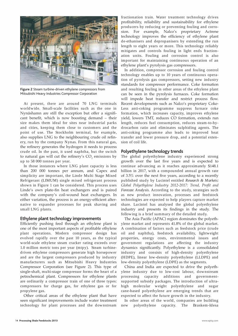
Ethylene plant technology improvementsEfficiently pushing feed through an ethylene plant is one of the most important aspects of profitable ethylene plant operations. Modern compressor design has evolved rapidly over the past 10 years, as the typical world-scale ethylene steam cracker rating exceeds over 1.0 million metric tons per year (mtpy). Steam turbine-driven ethylene compressors generate high horsepower and are the largest compressors produced by industry manufacturers such as Mitsubishi Heavy Industries Compressor Corporation (see Figure 2). This type of single-shaft, multi-stage compressor forms the heart of a petrochemical plant. Compressors for ethylene plants are ordinarily a compressor train of one of three types: compressors for charge gas, for ethylene gas or for propylene gas.
Other critical areas of the ethylene plant that have seen significant improvements include water treatment technology for plant processes and the downstream
fractionation train. Water treatment technology drives profitability, reliability and sustainability for ethylene producers by reducing or preventing fouling and corro-sion. For example, Nalco’s proprietary Actrene technology improves the efficiency of ethylene plant de-ethanisers and depropanisers by extending the run length to eight years or more. This technology reliably mitigates and controls fouling in light ends fraction-ation units. Fouling and corrosion control is also important for maintaining continuous operation of an ethylene plant’s pyrolysis gas compressors.
In addition, compressor corrosion and fouling control technology enables up to 10 years of continuous opera-tion of pyrolysis gas compressors, setting new industry standards for compressor performance. Coke formation and resulting fouling in other areas of the ethylene plant can be seen in the pyrolysis furnaces. Coke formation will impede heat transfer and restrict process flow. Recent developments such as Nalco’s proprietary Coke-Less anti-coking programme suppress furnace coke formation, which increases capacity, improves ethylene yield, lowers TMT, reduces CO formation, extends run length, reduces fuel consumption, reduces steam-to-hy-drocarbon ratio and eliminates sulphiding agents. The anti-coking programme also leads to improved heat transfer and lower pressure drop, and a potential exten-sion of coil life.
Polyethylene technology trendsThe global polyethylene industry experienced strong growth over the last five years and is expected to continue advancing as it reaches approximately $148.1 billion in 2017, with a compounded annual growth rate of 3.5% over the next five years, according to a recently published study by Lucintel entitled Research & Markets: Global Polyethylene Industry 2012-2017: Trend, Profit and Forecast Analysis. According to the study, strategies such as new product innovation, processes and feedstock technologies are expected to help players capture market share. Lucintel has analysed the global polyethylene industry and presents its findings in the study. The following is a brief summary of the detailed study.
The Asia Pacific (APAC) region dominates the polyeth-ylene market and represents 41.8% of the global market. A combination of factors such as feedstock price (crude oil and naphtha), feedstock availability, lightweight properties, energy costs, environmental issues and government regulations are affecting the industry dynamics significantly. Polyethylene is a consolidated industry and consists of high-density polyethylene (HDPE), linear low-density polyethylene (LLDPE) and low-density polyethylene (LDPE) as the segments.
China and India are expected to drive the polyeth-ylene industry due to low-cost labour, downstream processing capacity additions and government- supported subsidy packages. The introduction of ultra-high molecular weight polyethylene and sugar cane-based polyethylene are emerging trends that are expected to affect the future growth in the industry.
In other areas of the world, companies are building new polyethylene capacity. The Braskem-Idesa
The execution of functional safety assessment and validation must take place on every safety project and must be carried out by functional safety experts
Figure 2 Steam turbine-driven ethylene compressors from Mitsubishi Heavy Industries Compressor Corporation
proc trends .indd 3 26/02/2013 11:16
polyethylene project in Mexico is a good example of new polyethylene production plant project scope and objectives. This project, named Ethylene XXI, will be the largest private petrochemical facility in Mexico. It is being built in the city of Nanchital in the municipal-ity of Veracruz, in southeast Mexico. It will produce 1.05 million tonnes of polyethylene a year from ethane feedstock. Braskem-Idesa is a joint venture between Brazilian petrochemical company Braskem and a Mexican petrochemical group, Grupo Idesa. Braskem and Idesa respectively hold 65% and 35% interest in the joint venture.
The purpose of the project is to reduce the gap between Mexico’s local polyethylene production and demands, which are currently being met by importing one million tonnes of polyethylene every year.
The joint venture will own and operate the polyeth-ylene production facility. The construction of the facility is estimated to cost approximately $2.5 to $3 billion, which will represent the biggest foreign direct investment (FDI) in Mexico by a private Brazilian company.
The integrated petrochemical complex will include an ethane cracker, two HDPE plants and an LDPE plant. The ethane cracker will have a nominal capacity of about 1.0 million tonnes per annum. The first HDPE plant will have a capacity of approximately 400 000 tonnes per annum, while the second HDPE plant will produce 350 000 tonnes of polyethylene per annum. The LDPE will have a nominal production capacity of 300 000 tonnes per annum.
The twin HDPE plants will be based on the propri-etary Innovene S slurry high-density PE technology developed by Ineos Technologies. According to avail-able information, the Innovene S slurry process requires low investment and operating costs. It features two-reactor bimodal technology and combines circulation, heat exchange and reaction volume all in one system.
The lone LDPE plant will be based on LyondellBasell’s proprietary Lupotech T process tech-nology, one of the world’s most widely used high-pressure LDPE processes. Technology for the upstream ethylene cracker plant will be supplied by Technip.
Ethane that will be used as raw material for the Veracruz polyethylene manufacturing facility will be supplied by Pemex Gas y Petroquímica Básica (Pemex Gas). As per an agreement signed between Braskem-Idesa and Pemex Gas, the latter will supply 66 000 barrels of ethane a day for a period of 20 years. The project is located in close proximity to the Pemex facili-ties, which provides easy access to ethane. The site also has easy access to highways, railroads and ports.
Mitsubishi Heavy Industries Compressor Corporation (MCO), a wholly owned subsidiary of Mitsubishi Heavy Industries (MHI), was involved in supplying five compressors and three steam turbines for the facility. GE was contracted in April 2012 to supply its hyper-compressor and booster compressor technologies for the LDPE plant.
www.eptq.com
SAMSON AG · MESS- UND REGELTECHNIK Weismüllerstraße 3 60314 Frankfurt am Main · GermanyPhone: +49 69 4009-0 · Fax: +49 69 4009-1507 E-mail: [email protected] Internet: www.samson.deSAMSON GROUP · www.samsongroup.net
A01
120E
N
Partner with the Best
With over 50 independent subsidiar-ies and more than 220 engineering and sales offi ces spread across the world, SAMSON ensures the safety and environmental compatibility of your plants on any continent.
To offer the full range of high-quality control equipment used in industrial processes, SAMSON has brought together highly specialized compa-nies to form the SAMSON GROUP.
proc trends .indd 4 27/02/2013 10:52
NATCO
Cameron
PETRECO
RAISING PERFORMANCE. TOGETHER™
AD00387P
F L O W E Q U I P M E N T L E A D E R S H I P
CAMERON®
CONSEPT ®
CYNARA®
HYDROMATION®
KCC™
METROL®
MOZLEY®
NATCO®
PETRECO®
PORTA-TEST®
TST-CFU™
UNICEL®
VORTOIL®
WEMCO®
As the industry’s most comprehensive solutions provider, Cameron’s Process Systems
division integrates the strengths of NATCO and PETRECO to deliver a wide range
of solutions for today’s refiners.
• Industry-leading engineering expertise
• Diverse portfolio of solutions and services
• Extensive aftermarket services network
• Project management capabilities
Discover a higher level of performance and value at www.c-a-m.com/ProcessSystems
Integrated Strengths and Refining Solutions.Cameron’s Process Systems division delivers advanced products and processes for your refining needs.
• Industry-leading product support
• Advanced laboratory and pilot testing
• Full-service project support
• Cameron commitment to quality
CAMER-1125_Refining_PTQ.indd 1 2/21/13 9:50 AMcameron.indd 1 25/02/2013 15:00
Shale gas feeds petrochemical expansion
Capital investment for petro-chemical projects now on the books will bring petrochemi-
cal project activity in North America to a level not seen since the 1960s. These process invest-ments are primarily related to ethane-based steam crackers and other olefins-producing assets. Other major investments include propane dehydrogenation (PDH) units, gas-to-liquids (GTL) plants, methanol and aromatics production facilities. In parallel, the 500 or so midstream gas processing, gas treating and fractionation facilities in the continental US will need to be upgraded or expanded to meet pipeline specifications (with refer-ence to corrosive CO2, H2S, nitrogen, water and so on) in the transport of shale-based natural gas (as well as conventional gas) to new steam crackers and planned LNG export facilities.
Since the 1970s, several genera-tions of high natural gas prices in North America have led to an over-seas exodus of the petrochemical industry. Actually, it was not only petrochemical processors that left North America — alumina, ferti-lizer, cement, steel mills and other energy-intensive manufacturing industries also found other coun-tries with lower fixed and variable costs. However, energy costs based on $3.50/MMBtu (or less) for natu-ral gas are bringing these industries back to the US. Natural gas prices in Europe and Asia are expected to remain relatively high (>$12 MMBtu) in the long term.
Since it costs, on average, $8.0 to $10.0 million to bring a new shale well into commercial production,
North American ethylene capacity is set to increase significantly with new crackers coming online after 2016, plus higher production of propylene and other derivatives
ReNé GoNzAlez
upstream drillers are challenged to turn a profit with natural gas prices at their current low levels. Shale liquids production (crude oil and condensate) is currently the profit driver for the upstream drilling business. But beyond 2016, the onus is on leveraging the plentiful and cheap suppliers of natural gas (“wet” and “dry” gas) in the US for LNG export and as feedstock (primarily ethane) for at least seven world-scale steam crackers
announced in the US. In addition, about 15 licences had been submit-ted to US authorities as of December 2012 for construction of LNG liquefaction facilities and export terminals. However, most experts doubt that all 15 LNG projects will come to fruition due to political factors, environmental opposition and shifting global market dynamics.
Variability complicates gas treatmentWhile there are close to 500 gas processing plants in North America, older low-volume processing plants are being replaced with new plants that are
more efficient. In addition, these plants are large-volume operations, increasing overall daily processing capacity, according to James Tobin, Natural Gas Industry Analyst for EIA. It also appears, he says, that more gas treatment plants are being built because many unconventional gas wells yield fewer natural gas liquids. This leads Tobin to conclude that the gas treating market is growing faster than the processing segment.
There is a lot of variability in shale gas quality relative to conven-tional gas, according to experts. For example, Keith Bullin, Senior Consulting Engineer for Bryan Research & Engineering (BR&E), recently noted that the Antrim Shale has a high nitrogen concen-tration, whereas New Albany shale wells show high CO2 concentra-tions. Economically treating and processing these gases requires the ability to handle a great deal of variability in the same field.
Treatment often begins at the well-head, offers Bob Dunn, President of the Gas Processors Association (GPA). Contaminants such as highly corrosive CO2 and H2S are removed at a treatment facility near the field or at a gas processing plant. “Removing the CO2 near the field is often done for pipeline protection,” he remarks.
Pipeline quality standards limit the amount of CO2, nitrogen, oxygen and water vapour in the gas stream, in addition to a heating value limit of about 1035 Btu per cubic foot. In some cases, when plants are not yet available, waivers are granted for a limited time, according to Dunn. This enables
www.eptq.com Processing Shale Feedstocks 2013 17
Shale liquids production (crude oil and condensate) is currently the profit driver for the upstream drilling business
rene.indd 1 25/02/2013 19:27
18 Processing Shale Feedstocks 2013 www.eptq.com
said the expansion plans were in response to new low-cost ethane and other light NGLs becoming available as a result of shale gas production. Expansion of Petro 1, originally set for year-end 2014, is scheduled for 2015. Before the projects were announced, cracker capacity was 567 000 tpy and 522 000 tpy, respectively.
Midstream services company Enterprise Products recently reported it will build a PDH unit in Texas. In order to meet global market requirements for polymer-grade and chemical-grade propylene, almost two dozen PDH units have been announced since 2010, primarily in China. Similar units are beginning to be announced in the US to meet the growing propylene deficit. Numerous refinery FCC units throughout the world have been reconfigured to increase propylene production. Propylene-producing FCC technology has scored numer-ous successes over the past 18 months, with new units announced in Thailand, Brazil and elsewhere. However, in the US, refinery-based propylene production is still not in sufficient volumes to compensate for the disproportionately lower propylene production from ethane-based steam crackers.
The Enterprise Products PDH unit will have a capacity of 750 000 tonnes/year of polymer-grade propylene (PGP) and will use 35 000 bpd of propane feedstock.
producers to begin marketing gas from new fields as the processing plant is built.
If the gas is not pipeline quality, it typically is processed at a refrig-eration or cryogenic plant. In refrigeration units, the gas is cooled and the NGLs precipitate out, explains Bullin, removing more than 90% of the propane and about 40% of the ethane. Other heavier components are almost entirely removed.
In cryogenic units, gas tempera-ture is reduced to -120 to -150°F, he explains. The temperature drop causes the ethane and other heavier hydrocarbons to condense, remov-ing more of the natural gas liquids and 90-95% of the ethane.
As previously noted, there were more than 500 gas processing plants in the US before 2005. Most of these were small, relative to the size of a typical crude oil refinery, and were in remote areas of the US Southwest and the Rocky Mountains. Since that time, addi-tional plants have been added at least in part to address demand in unconventional gas plays. This has resulted in the need to build modu-lar facilities in areas where gas processing and gas treating facili-ties previously did not exist, such as in North Dakota. Other shale plays, including Niobrara, Woodford, Eagle Ford, Marcellus and Barnett, are ramping up natu-ral gas plant capacity. When a horizontally drilled shale gas well
starts flowing, there is often a tremendous increase in volume, making it critical that the infra-structure is in place to process the gas and move it to market.
Prior to the 1990s, most process-ing operations were owned by the pipeline or gas production compa-nies. When a producer planned to develop new fields, the processors were fully informed and could build capacity to match production. There are now many independent midstream processors, which relieves pipelines and/or producers of the capital requirements for processing, but also raises coordi-nation issues that are a big challenge for emerging shale markets, making coordination between service providers and producers one of the biggest busi-ness challenges in the industry.
Ethane-based steam cracking Competitive economics that could not have been foreseen only three years ago now make ethane-based steam cracking projects in the US competitive against other ethane and naphtha/gas oil steam crackers in Asia and Europe. For example, Westlake Chemical in Houston will perform planned maintenance and an expansion of the Petro 2 ethyl-ene unit at the company’s complex in Lake Charles, Louisiana, in Q1 2013. This expansion will increase ethane-based ethylene capacity by about 104 000-109 000 tonnes/year (tpy). In 2011, Westlake Chemical
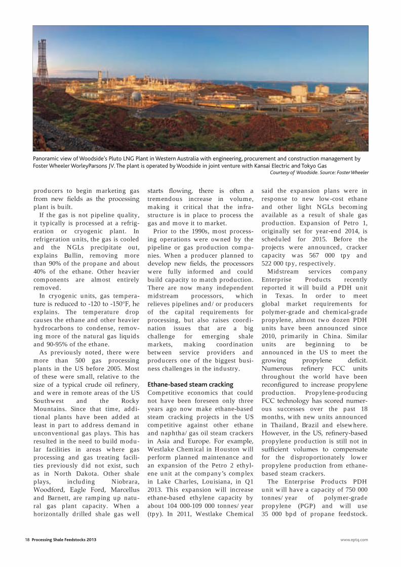
Panoramic view of Woodside’s Pluto LNG Plant in Western Australia with engineering, procurement and construction management by Foster Wheeler WorleyParsons JV. The plant is operated by Woodside in joint venture with Kansai Electric and Tokyo Gas CourtesyofWoodside.Source:FosterWheeler
rene.indd 2 25/02/2013 19:27
www.eptq.com Processing Shale Feedstocks 2013 19
The facility should be operational by 2015, Enterprise said. The company did not disclose the finan-cial details. “By 2015, with completion of expansions that have already been announced, Enterprise would have 708 000 bpd of [natural gas liquids] NGL fractionation capacity, which would provide up to 177 000 bpd of propane supply,” says the company. “Enterprise also has PGP storage facilities and a 102-mile [164 km] pipeline system, capable of delivering PGP to 18 downstream customers and to international markets through the partnership’s propylene export terminal in Seabrook, Texas,” adds the company.
In 2010, PetroLogistics brought on stream the world’s largest PDH unit on the Houston Ship Channel. “Some people may have that thought that was crazy at the time,” recalls Chuck Carr, Director of Propylene Studies at IHS Chemical. “But we now forecast about 150 000 bpd of propane demand is going to be added in North America by 2020. All of that is from the chemi-cal industry, with the North American fuel market for propane forecast for minimal growth.” The biggest and most recent move in propane is a plan by Dow Chemical to get into dehydrogenation. Dow announced in 2012 that it will produce propylene at its Freeport, Texas, complex using PDH technol-ogy. The Freeport complex is one of the largest chemical manufacturing sites in the world. The facility will produce 750 000 metric tons annu-ally of PGP and is scheduled to come on stream in 2015. The company says the facility will be the largest single-train PDH plant in North America.
Expanding infrastructureUse as a fuel directly and to gener-ate power remain by far the primary markets for natural gas, but the shale revolution has wrought fundamental change in the upstream market. Chemical compa-nies across North America are beginning to believe in the new reality of plentiful and reasonably priced natural gas. Petrochemical industries, including olefins
producers, PDH, polymer and aromatics producers all expect North American natural gas prices, currently at $3.45 per MMBtu at the end of January 2013, to remain competitive for the long term. Lawmakers in the US government, including 89 Republicans and 21 Democrats, petitioned US Department of Energy (DOE) Secretary Steven Chu on 31 January to move forward with allowing construction of liquefaction facili-ties and LNG terminals for exporting LNG to European and Asian markets, where gas sells three and four times as much as it does in the US market.
US manufacturers, power genera-tors and chemical processors are opposed to LNG exports for fear
that natural gas prices will skyrocket as a result of multiple LNG export outlets. However, many analysts believe shale gas production will continue to expand so that only slight increases in gas prices can be expected with a simultaneous LNG export market and a growing domestic consump-tion, primarily by the petrochemical processing industry.
According to a 25 January report by Jennifer A Diouhy in the Houston Chronicle concerning the new LNG export opportunities from the US: “Additional costs of liquefying [cryogenic liquefaction] natural gas, shipping it overseas and then converting it again at its destination could add $6.30 to $8.39 to the price per MMBtu,” as she
noted from a government commis-sioned study. She noted that the DOE is reviewing applications from more than a dozen companies (15 companies have submitted applica-tions for LNG export facilities at press time) to export at least 22.6 bcf of natural gas to countries that do not have free trade agreements with the US. Post-Fukushima Japan, for instance, is eager to find power sources to replace nuclear power after the 2011 earthquake and tsunami that nearly destroyed the Fukushima Dai-Ichi plant. To be sure, the growing demand for safe and clean power sources through-out the world puts natural gas at the forefront not only as a petro-chemical feedstock, but as a “base load” power source instead of coal.
Methane, the most basic hydro-carbon molecule with one carbon atom attached to four hydrogen atoms (CH4) is not simply for turn-ing generators and heating beans on the stove; it is also the primary feedstock for methanol and ammo-nia. While ethane is the primary natural gas molecule in shale gas, there is also a market for the meth-ane, propane and butane produced from most shale plays throughout the world. As previously noted, the main market in North America for ethane is as a feedstock for steam crackers to make ethylene. That, in turn, is made into polyethylene (used in plastics products) or other derivatives.
Propane and butane are mostly fuels, but the shift in steam cracker feed slates from naphtha and mixed natural gas liquids to primarily ethane means more ethylene out of the other end, and less of the important propylene and butadiene co-products. While it is clear that the PDH technology for propylene production has been gaining momentum since 2010, other petro-chemical manufacturers are also exploring methanol-to-olefins to increase propylene production. Needless to say, propylene is used primarily for polypropylene, another high-volume thermoplastic. Butadiene is an essential compo-nent in elastomers. Most tyres are styrene butadiene rubber; styrene is made from ethylene plus benzene
Competitive economics now make ethane-based steam cracking projects in the US competitive against other ethane and naphtha/gas oil steam crackers in Asia and Europe
rene.indd 3 25/02/2013 19:27
fundamental change in their busi-ness. “Shale gas and the associated NGLs are a game-changer for our members,” says Cooper. “We are reading on a weekly basis about expanded production and new chemistries based on this new supply of energy and feedstocks. The producers tell us that natural gas is affordable and plentiful, not just today, but on a structural and strategic-planning level. We expect it to be a dependable source for a long time,” Cooper continues.
Regardless as to how well capital-ised the upstream drilling and production business can expect to be over the next several years, adequate midstream infrastructure is required to efficiently transport natural gas feedstock to market. For example, two pipeline projects announced over the past year will transport ethane from Pennsylvania to major petrochemical centres. Last
year, Sunoco inked a deal to move ethane from the Marcellus shale region to Nova Chemical’s mega complex at Sarnia, Ontario. Then, in January, Enterprise Products Partners confirmed plans to build a 1230-mile line from Pennsylvania to the Gulf Coast, to begin commercial operations in Q1 2014.
Since post-World War II, pipeline projects completed from the Gulf Coast to the US East Coast have been too numerous to mention. In a radical turn of events, the Eastern Appalachia-to-Texas, or Atex line, will be built with an initial capacity of 190 000 bpd of ethane, and trans-port rates will start at $0.15 a gallon, according to Enterprise reports. Chesapeake Energy will be the anchor shipper, having commit-ted to 75 000 bpd over the first five years, the company says. To save time and money, other Gulf Coast
20 Processing Shale Feedstocks 2013 www.eptq.com
(ethyl benzene), with polystyrene constituting the third major thermoplastic.
As if to signal the dawn of a new era, the largest methanol producer in the world, Methanex Corporation, said early in January that it would relocate at least one of its idle trains from its complex in Cabo Negro, Chile, to an existing facility near Geismar, Louisiana. Site-specific engineering has begun, and the 1.0 million mtpy plant is expected to be operational in the second half of 2014. Early in February, Jacobs Engineering was awarded the contract to reconstruct the Geismar plant. At the time of the announcement, Bruce Aitken, President and Chief Executive Officer of Methanex, commented, “The outlook for low North American natural gas prices makes the State of Louisiana an attractive location in which to produce meth-anol. The timing of this project is excellent; there is strong demand growth for methanol globally and there is little new production capac-ity being added over the next several years.”
The Methanex plant is one of several that will increase North American methanol capacity by 158% to 3.48 million mtpy by 2014, according to Dewey Johnson, Senior Director of Chemical Market Research at IHS Chemical in Houston.
It takes 32 MMBtu of natural gas to make one metric ton of metha-nol, so 3.48 million metric tons of methanol requires 111.36 trillion Btu (111.36 bcf) of gas, says Johnson. By itself, increased metha-nol output is not enough to move the needle on US gas prices, but he notes that it is certainly a signifi-cant new source of demand. “Methanol and fertilizer from methane certainly are important end-use markets, but we look mostly at olefins, ethylene and co-products, and their derivatives,” says James Cooper, Vice President of Petrochemicals for the American Fuel & Petrochemical Manufacturers (AFPM) Association. For chemical producers, the shale gas boom has surpassed being merely a benefit to becoming a
to East Coast pipelines are being “reversed.”
Carlo Barrasa, Director of NGLs and Cracker Economics at IHS Chemical, estimates ethylene steam cracker feeds were about 40% ethane in the past generation. Barrasa says, “Today, feed slates are 70% ethane, and that will continue to creep higher every year.” Barrasa notes that at $0.44/gallon for ethane, the production cost for ethylene comes to $0.18/pound. “The market price for ethyl-ene is about $0.70/pound, so cracker operators are experiencing a tremendous profit margin right now,” he observed in early 2012. “They are taking any opportunity to optimise their trains to consume ethane,” he added.
Ethylene steam crackersIn June 2011, Shell announced that it was developing plans to build a large steam cracker with integrated derivative units in the Appalachian region. “Building an ethane-fed cracker in Appalachia will unlock significant gas production in the Marcellus by providing a local outlet for the ethane,” says Ben van Beurden, Shell’s Executive Vice President for Chemicals. “This fits well with our strategy to strengthen our chemicals feedstock advantage and would be another step in growing our chemicals business to meet increasing demand.” The company released a statement saying the complex included a steam cracker to turn ethane produced from the Marcellus into ethylene and other petrochemical building blocks. In addition to the cracker, Shell said in the release that it was “also considering poly-ethylene and monoethylene glycol units to help meet increasing demands in the North American market. Much of the polyethylene and monoethylene glycol produc-tion will be used by industries in the Northeast.”
In a news release, Shell says it has “an array of long-term options to monetize natural gas. Extracting ethane and other natural gas liquids (to produce) petrochemicals is one of these options, which also include developing shipping
“Shale gas represents a once-in-a-century change in the competitive balance worldwide”
rene.indd 4 25/02/2013 19:27
www.eptq.com Processing Shale Feedstocks 2013 21
hard pressed to change the new dynamics in the North American gas market.” For example, by several estimates, two-thirds of the plastics converters in North America are within 500 miles of the Marcellus Shale play, making the economics for world-scale ethane-fed steam crackers, the basic petrochemical to plastics building block, a viable option in what was previously thought of as an isolated market with limited opportunity for down-stream expansion, in spite of low ethane feedstock costs.
The American Chemistry Council recently completed a study entitled Shale Gas and New Petrochemicals Investment: Benefits for the Economy, Jobs and U.S. Manufacturing. It antic-ipates a $16.2 billion private investment over several years in new plant and equipment for manufacturing petrochemicals. That investment would lead to a 25% increase in US petrochemicals capacity and $32.9 billion in addi-tional chemical industry output, the study estimates.
from Haldor Topsøe and Fischer-Tropsch (FT) technology from Velocys. Haldor Topsøe’s ATR is a proprietary technology for reform-ing natural gas into synthesis gas, a mixture of hydrogen and carbon monoxide (CO). In the GTL plant, said the Calumet announcement, this synthesis gas will move through Velocys’s FT process, converting it into long-chain hydrocarbons, typi-cally paraffins, naphthenes and aromatic compounds.
Game changer“Shale gas represents a once-in-a-century change in the competitive balance worldwide,” according to Garrett Gee, Director of Chemical Advisory Services at Price-waterhouseCoopers. He added, “This is a major capital opportunity to play a global game very differ-ently.” He stresses that “Even if the estimates of shale gas supply are off by half, it still represents a huge volume of light hydrocarbons. Even if LNG exports of US-produced gas go ahead full out, all that would be
solutions for LNG; proprietary GTL technology to produce fuels, lubri-cants and chemicals; and gas-for-transport in markets focus-ing on heavy-duty vehicles, marine and rail transportation.” The situa-tion in the Marcellus is “a classic trapped ethane problem,” observes Mark Eramo, Vice President of Chemical Research and Analysis at IHS Chemical. “It is the same thing we saw in Saudi Arabia in the past two decades. You can either build a cracker on site and ship the deriva-tives, or you can build a pipeline to transport the ethane. Both are viable.”
Calumet Specialty Products Partners recently announced that it is considering adding a 1000 bpd GTL plant to its Karns City, Pennsylvania, speciality products plant. Production could begin in second-half 2014. Calumet has commissioned Pasadena, Texas-based Ventech Engineers International to design and deliver the GTL plant that will use a propri-etary autothermal reformer (ATR)
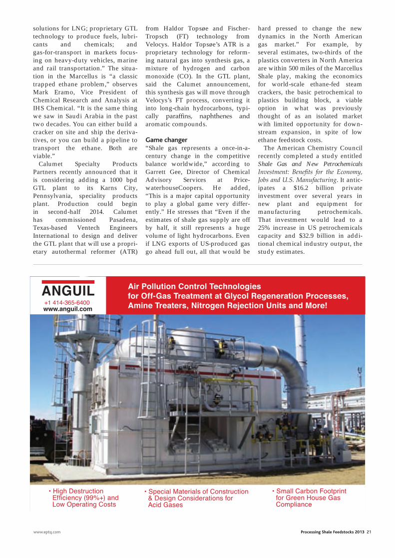
Air Pollution Control Technologiesfor Off-Gas Treatment at Glycol Regeneration Processes, Amine Treaters, Nitrogen Rejection Units and More!
• High Destruction Efficiency (99%+) and Low Operating Costs
• Small Carbon Footprint for Green House Gas Compliance
• Special Materials of Construction & Design Considerations for Acid Gases
+1 414-365-6400www.anguil.com
rene.indd 5 25/02/2013 19:28
propylene passion
Yet another sign that the world is aching for more
propylene. Profit from the global propylene gap with
a proven, innovative solution from UOP.
No matter what your feedstock and production realities,
UOP can bring you the on-purpose propylene solution that’s
just right for you: UOP OleflexTM (propane dehydrogenation)
process; UOP Advanced MTO Process; PetroFCCTM process; RxProTM process and
the Total Petrochemicals/UOP Olefin Cracking process. For nearly 100 years, UOP
has been developing the cutting-edge technologies our clients rely upon to drive their
growth, profitability and operational flexibility. Our broad propylene solution portfolio
is yet another example of our unwavering commitment to innovation.
Process Technology • Catalysts • Adsorbents • Performance Equipment • Profitability ConsultingUOP LLC, 25 East Algonquin Road, Des Plaines, IL 60017-5017, USA phone: +1-847-391-2000 fax: +1-847-391-2253 www.uop.com
© 2013 UOP LLC. All rights reserved.
UOP_Propylene_Passion_Ad_A5_Ad A5 148mmx210mm UOP6010 2/27/13 11:34 AM Page 1
uop.indd 1 28/02/2013 09:26
Driving down costs in hydrogen production
The global demand for refinery hydrogen has increased significantly over the past
decade due to changes in available crude feedstocks and tighter envi-ronmental regulations, which have forced the refining industry to reduce sulphur, olefins and aromat-ics content in transportation fuels. This, coupled with the continued growth in diesel demand, means that refiners are investing heavily in both hydrotreating and hydroc-racking facilities, and are constantly looking for access to low-cost, reliable sources of high-purity hydrogen.
Foster Wheeler pioneered steam methane reforming (SMR) technol-ogy and has delivered more than 100 hydrogen and synthesis gas plants around the world, with a total installed capacity of more than 3.5 million Nm3/h of hydrogen. The company’s patented and proprietary Terrace Wall reformer furnace was developed in conjunc-tion with SMR technology in the early 1960s. Updates and improve-ments to plant efficiency, lower maintenance costs, simplified oper-ations and enhanced plant safety have been documented in previ-ously published articles.
These hydrogen-producing SMR plants process a wide range of feedstocks from natural gas to naphtha and range in size from 5000 to 200 000 Nm3/h. The range of hydrogen solutions provided include:• Optimised plant design and oper-ating parameters tailored to the operator’s requirements, integrating overall plant and reformer furnace design to reduce total lifecycle costs
An optimised hydrogen plant design achieves the right balance of minimising both Capex and Opex costs, while meeting the specific objectives of the end user
Luigi BressAn and Chris DAvisFoster Wheeler
• Full understanding of constructa-bility issues and impact on total installed cost, with the ability to incorporate a high degree of modu-larisation of the Terrace Wall reformer, reducing construction costs• One-stop shop, providing consist-ency through all design phases, ensuring single-point accountability for process and operational guarantees• Safety in design that incorporates the latest state-of-the-art design principles as well as end user feed-back, to enable safe and reliable plant operations.
steam reformer-based technologySMR continues to be the leading technology for hydrogen produc-tion and, although it is a mature technology, incremental economic improvements are being continu-ously developed, which improve overall plant efficiency, reduce the cost of hydrogen production and minimise the impact on the envi-ronment by reducing CO2 emissions.
The hydrogen production plant consists of five main sections:• Treatment section Feedstock is hydrotreated and the resulting H2S is captured in a zinc oxide bed. Different schemes are available, with the most commonly used being a lead-lag reactor arrange-ment. Reaction temperatures are obtained by thermal exchange in the reformer’s heater convection section• Pre-reforming section A pre- reforming section is generally installed to eliminate the long-chain hydrocarbons in heavier feedstocks
before they enter the reforming section. When natural gas is used as a feedstock, the pre-reforming section helps to reduce the reform-ing duty, thereby lowering the initial investment cost of the reformer• reforming section This is the heart of the plant and will be discussed in detail in the next section. The Terrace Wall technol-ogy allows for steam reformer outlet temperatures of up to 930°C• syngas cooling and shift reaction section For the shift reaction, four options are available: high-temper-ature shift (HTS), HTS and low-temperature shift (HTS + LTS), medium-temperature shift (MTS) and isothermal shift (ITS). The syngas cooling section is normally optimised using pinch technology• Pressure swing adsorption (PsA) section Final hydrogen purification is typically achieved using PSA, as this technology is both effective and well known. Process parame-ters need to be carefully defined to optimise both overall cost and operating expenses.
The centrepiece of Foster Wheeler’s hydrogen plant design is the Terrace Wall reformer. This design incorporates unique features that provide controlled heat trans-fer to the reformer catalyst tubes, which translates into longer tube life, longer catalyst life and better stability at turndown conditions.
general descriptionThe Terrace Wall reformer, shown in Figure 1, features a radiant section consisting of a firebox, which contains a single row of cata-lyst tubes with burners on either
www.eptq.com Processing Shale Feedstocks 2013 23
fw.indd 1 25/02/2013 19:33
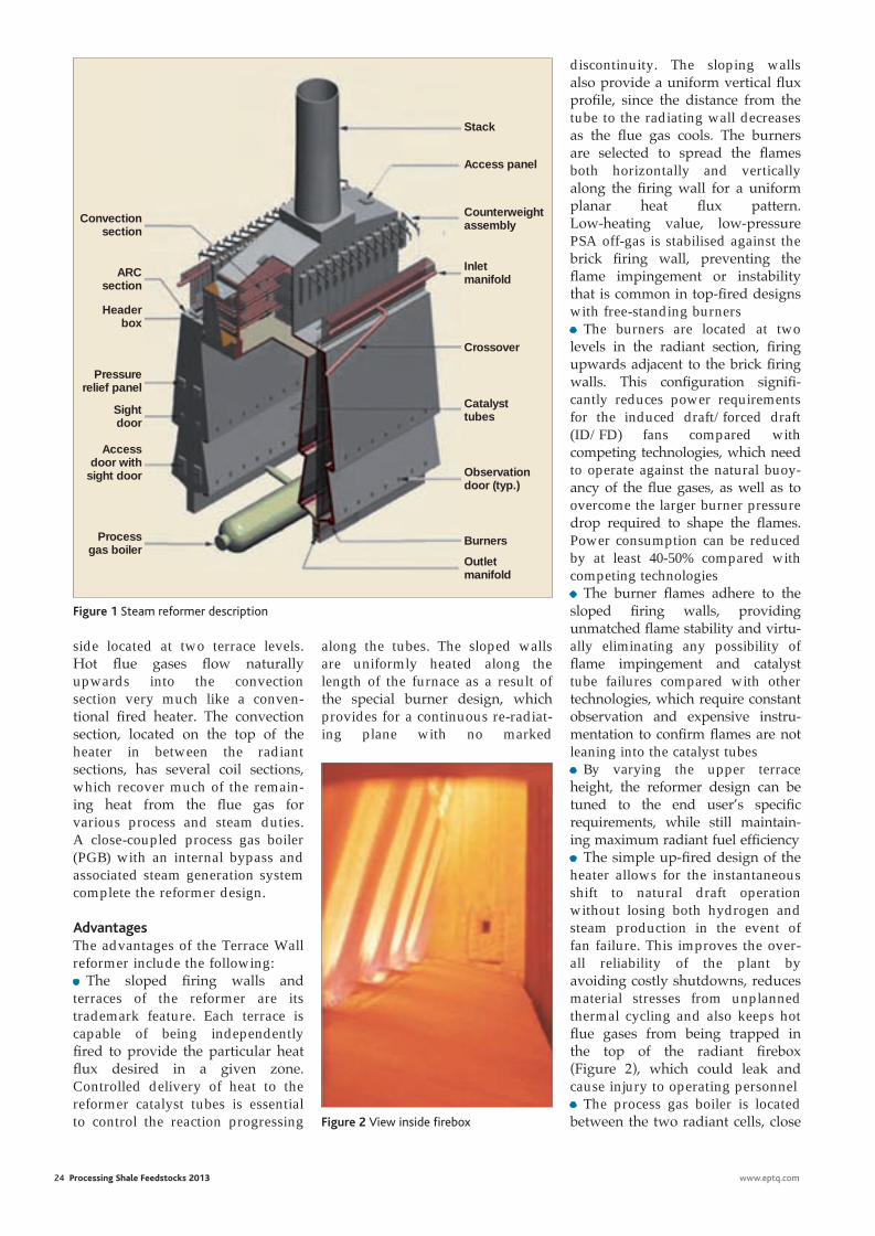
24 Processing Shale Feedstocks 2013 www.eptq.com
discontinuity. The sloping walls also provide a uniform vertical fl ux profi le, since the distance from the tube to the radiating wall decreases as the fl ue gas cools. The burners are selected to spread the fl ames both horizontally and vertically along the fi ring wall for a uniform planar heat fl ux pattern. Low-heating value, low-pressure PSA off-gas is stabilised against the brick fi ring wall, preventing the fl ame impingement or instability that is common in top-fi red designs with free-standing burners • The burners are located at two levels in the radiant section, fi ring upwards adjacent to the brick fi ring walls. This confi guration signifi -cantly reduces power requirements for the induced draft/forced draft (ID/FD) fans compared with competing technologies, which need to operate against the natural buoy-ancy of the fl ue gases, as well as to overcome the larger burner pressure drop required to shape the fl ames. Power consumption can be reduced by at least 40-50% compared with competing technologies• The burner fl ames adhere to the sloped fi ring walls, providing unmatched fl ame stability and virtu-ally eliminating any possibility of fl ame impingement and catalyst tube failures compared with other technologies, which require constant observation and expensive instru-mentation to confi rm fl ames are not leaning into the catalyst tubes • By varying the upper terrace height, the reformer design can be tuned to the end user’s specifi c requirements, while still maintain-ing maximum radiant fuel effi ciency• The simple up-fi red design of the heater allows for the instantaneous shift to natural draft operation without losing both hydrogen and steam production in the event of fan failure. This improves the over-all reliability of the plant by avoiding costly shutdowns, reduces material stresses from unplanned thermal cycling and also keeps hot fl ue gases from being trapped in the top of the radiant fi rebox (Figure 2), which could leak and cause injury to operating personnel• The process gas boiler is located between the two radiant cells, close
side located at two terrace levels. Hot fl ue gases fl ow naturally upwards into the convection section very much like a conven-tional fi red heater. The convection section, located on the top of the heater in between the radiant sections, has several coil sections, which recover much of the remain-ing heat from the fl ue gas for various process and steam duties. A close-coupled process gas boiler (PGB) with an internal bypass and associated steam generation system complete the reformer design.
AdvantagesThe advantages of the Terrace Wall reformer include the following: • The sloped fi ring walls and terraces of the reformer are its trademark feature. Each terrace is capable of being independently fi red to provide the particular heat fl ux desired in a given zone. Controlled delivery of heat to the reformer catalyst tubes is essential to control the reaction progressing
along the tubes. The sloped walls are uniformly heated along the length of the furnace as a result of the special burner design, which provides for a continuous re-radiat-ing plane with no marked
Convection section
ARC section
Header box
Pressure relief panel
Sight door
Access door with
sight door
Process gas boiler
Outlet manifold
Burners
Observation door (typ.)
Catalyst tubes
Crossover
Inlet manifold
Counterweight assembly
Access panel
Stack
Figure 1 Steam reformer description
Figure 2 View inside fi rebox
fw.indd 2 25/02/2013 19:33
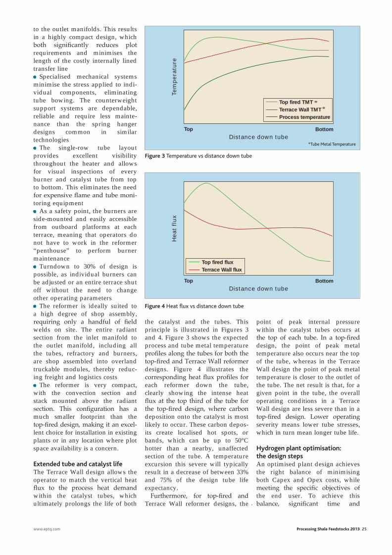
www.eptq.com Processing Shale Feedstocks 2013 25
to the outlet manifolds. This results in a highly compact design, which both significantly reduces plot requirements and minimises the length of the costly internally lined transfer line • Specialised mechanical systems minimise the stress applied to indi-vidual components, eliminating tube bowing. The counterweight support systems are dependable, reliable and require less mainte-nance than the spring hanger designs common in similar technologies • The single-row tube layout provides excellent visibility throughout the heater and allows for visual inspections of every burner and catalyst tube from top to bottom. This eliminates the need for expensive flame and tube moni-toring equipment • As a safety point, the burners are side-mounted and easily accessible from outboard platforms at each terrace, meaning that operators do not have to work in the reformer “penthouse” to perform burner maintenance• Turndown to 30% of design is possible, as individual burners can be adjusted or an entire terrace shut off without the need to change other operating parameters• The reformer is ideally suited to a high degree of shop assembly, requiring only a handful of field welds on site. The entire radiant section from the inlet manifold to the outlet manifold, including all the tubes, refractory and burners, are shop assembled into overland truckable modules, thereby reduc-ing freight and logistics costs • The reformer is very compact, with the convection section and stack mounted above the radiant section. This configuration has a much smaller footprint than the top-fired design, making it an excel-lent choice for installation in existing plants or in any location where plot space availability is a concern.
Extended tube and catalyst lifeThe Terrace Wall design allows the operator to match the vertical heat flux to the process heat demand within the catalyst tubes, which ultimately prolongs the life of both
the catalyst and the tubes. This principle is illustrated in Figures 3 and 4. Figure 3 shows the expected process and tube metal temperature profiles along the tubes for both the top-fired and Terrace Wall reformer designs. Figure 4 illustrates the corresponding heat flux profiles for each reformer down the tube, clearly showing the intense heat flux at the top third of the tube for the top-fired design, where carbon deposition onto the catalyst is most likely to occur. These carbon depos-its create localised hot spots, or bands, which can be up to 50°C hotter than a nearby, unaffected section of the tube. A temperature excursion this severe will typically result in a decrease of between 33% and 75% of the design tube life expectancy.
Furthermore, for top-fired and Terrace Wall reformer designs, the
point of peak internal pressure within the catalyst tubes occurs at the top of each tube. In a top-fired design, the point of peak metal temperature also occurs near the top of the tube, whereas in the Terrace Wall design the point of peak metal temperature is closer to the outlet of the tube. The net result is that, for a given point in the tube, the overall operating conditions in a Terrace Wall design are less severe than in a top-fired design. Lower operating severity means lower tube stresses, which in turn mean longer tube life.
Hydrogen plant optimisation: the design stepsAn optimised plant design achieves the right balance of minimising both Capex and Opex costs, while meeting the specific objectives of the end user. To achieve this balance, significant time and
Top Bottom
Tem
pera
ture
Distance down tube
Process temperature
Top fired TMTTerrace Wall TMT
Top Bottom
Heat
flux
Distance down tube
Top fired fluxTerrace Wall flux
Figure 3 Temperature vs distance down tube
Figure 4 Heat flux vs distance down tube
**
*Tube Metal Temperature
fw.indd 3 25/02/2013 19:33
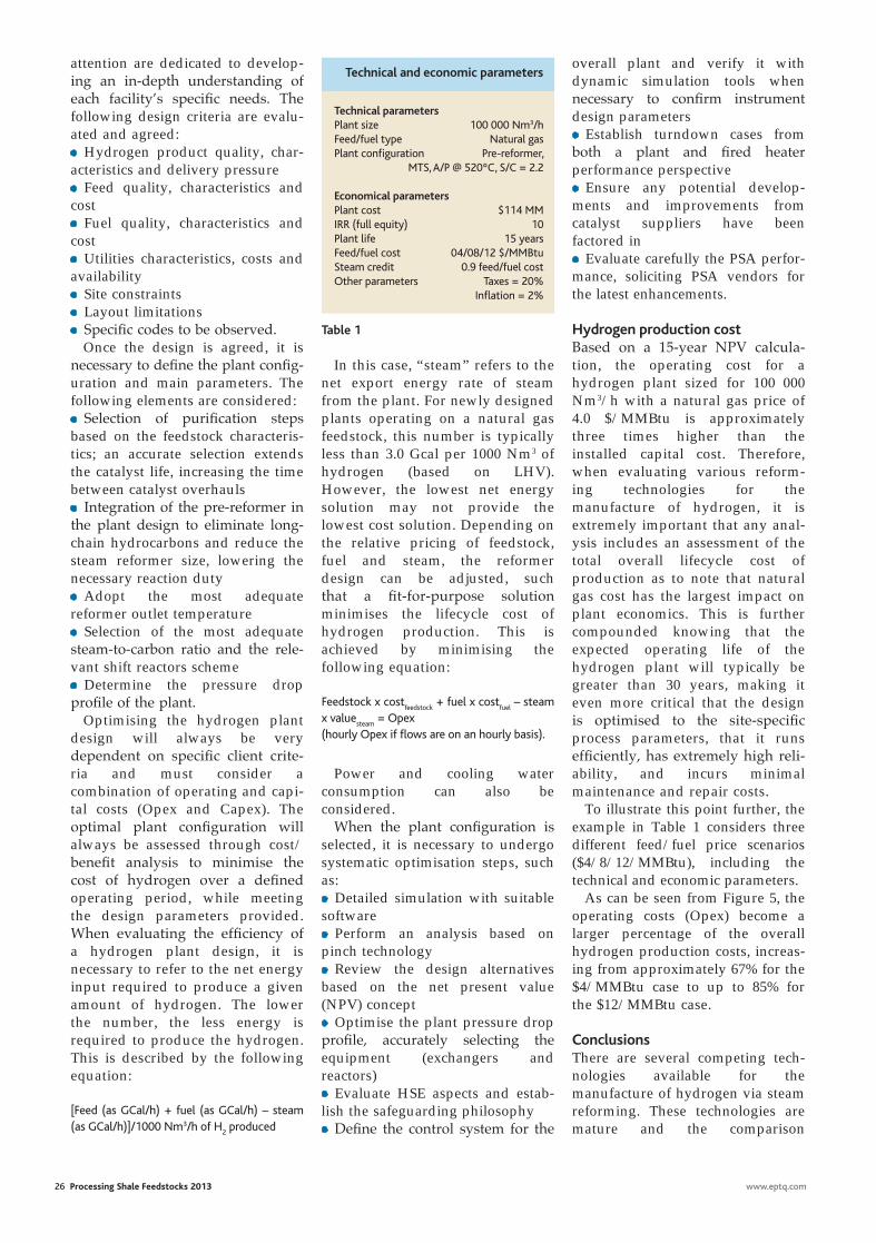
In this case, “steam” refers to the net export energy rate of steam from the plant. For newly designed plants operating on a natural gas feedstock, this number is typically less than 3.0 Gcal per 1000 Nm3 of hydrogen (based on LHV). However, the lowest net energy solution may not provide the lowest cost solution. Depending on the relative pricing of feedstock, fuel and steam, the reformer design can be adjusted, such that a fit-for-purpose solution minimises the lifecycle cost of hydrogen production. This is achieved by minimising the following equation:
Feedstock x costfeedstock
+ fuel x costfuel
– steam x value
steam = Opex
(hourly Opex if flows are on an hourly basis).
Power and cooling water consumption can also be considered.
When the plant configuration is selected, it is necessary to undergo systematic optimisation steps, such as:• Detailed simulation with suitable software • Perform an analysis based on pinch technology• Review the design alternatives based on the net present value (NPV) concept• Optimise the plant pressure drop profile, accurately selecting the equipment (exchangers and reactors)• Evaluate HSE aspects and estab-lish the safeguarding philosophy• Define the control system for the
26 Processing Shale Feedstocks 2013 www.eptq.com
attention are dedicated to develop-ing an in-depth understanding of each facility’s specific needs. The following design criteria are evalu-ated and agreed:• Hydrogen product quality, char-acteristics and delivery pressure• Feed quality, characteristics and cost• Fuel quality, characteristics and cost• Utilities characteristics, costs and availability• Site constraints• Layout limitations• Specific codes to be observed.
Once the design is agreed, it is necessary to define the plant config-uration and main parameters. The following elements are considered:• Selection of purification steps based on the feedstock characteris-tics; an accurate selection extends the catalyst life, increasing the time between catalyst overhauls• Integration of the pre-reformer in the plant design to eliminate long-chain hydrocarbons and reduce the steam reformer size, lowering the necessary reaction duty• Adopt the most adequate reformer outlet temperature• Selection of the most adequate steam-to-carbon ratio and the rele-vant shift reactors scheme• Determine the pressure drop profile of the plant.
Optimising the hydrogen plant design will always be very dependent on specific client crite-ria and must consider a combination of operating and capi-tal costs (Opex and Capex). The optimal plant configuration will always be assessed through cost/benefit analysis to minimise the cost of hydrogen over a defined operating period, while meeting the design parameters provided. When evaluating the efficiency of a hydrogen plant design, it is necessary to refer to the net energy input required to produce a given amount of hydrogen. The lower the number, the less energy is required to produce the hydrogen. This is described by the following equation:
[Feed (as GCal/h) + fuel (as GCal/h) – steam (as GCal/h)]/1000 Nm3/h of H
2 produced
overall plant and verify it with dynamic simulation tools when necessary to confirm instrument design parameters• Establish turndown cases from both a plant and fired heater performance perspective• Ensure any potential develop-ments and improvements from catalyst suppliers have been factored in• Evaluate carefully the PSA perfor-mance, soliciting PSA vendors for the latest enhancements.
Hydrogen production costBased on a 15-year NPV calcula-tion, the operating cost for a hydrogen plant sized for 100 000 Nm3/h with a natural gas price of 4.0 $/MMBtu is approximately three times higher than the installed capital cost. Therefore, when evaluating various reform-ing technologies for the manufacture of hydrogen, it is extremely important that any anal-ysis includes an assessment of the total overall lifecycle cost of production as to note that natural gas cost has the largest impact on plant economics. This is further compounded knowing that the expected operating life of the hydrogen plant will typically be greater than 30 years, making it even more critical that the design is optimised to the site-specific process parameters, that it runs efficiently, has extremely high reli-ability, and incurs minimal maintenance and repair costs.
To illustrate this point further, the example in Table 1 considers three different feed/fuel price scenarios ($4/8/12/MMBtu), including the technical and economic parameters.
As can be seen from Figure 5, the operating costs (Opex) become a larger percentage of the overall hydrogen production costs, increas-ing from approximately 67% for the $4/MMBtu case to up to 85% for the $12/MMBtu case.
ConclusionsThere are several competing tech-nologies available for the manufacture of hydrogen via steam reforming. These technologies are mature and the comparison
Technical parametersPlant size 100 000 Nm3/hFeed/fuel type Natural gasPlant configuration Pre-reformer, MTS, A/P @ 520ºC, S/C = 2.2
Economical parametersPlant cost $114 MMIRR (full equity) 10Plant life 15 yearsFeed/fuel cost 04/08/12 $/MMBtuSteam credit 0.9 feed/fuel costOther parameters Taxes = 20% Inflation = 2%
Technical and economic parameters
Table 1
fw.indd 4 25/02/2013 19:33
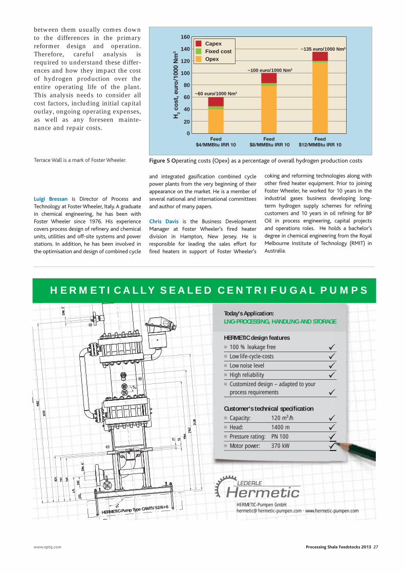
www.eptq.com Processing Shale Feedstocks 2013 27
and integrated gasification combined cycle power plants from the very beginning of their appearance on the market. He is a member of several national and international committees and author of many papers.
Chris Davis is the Business Development Manager at Foster Wheeler’s fired heater division in Hampton, New Jersey. He is responsible for leading the sales effort for fired heaters in support of Foster Wheeler’s
between them usually comes down to the differences in the primary reformer design and operation. Therefore, careful analysis is required to understand these differ-ences and how they impact the cost of hydrogen production over the entire operating life of the plant. This analysis needs to consider all cost factors, including initial capital outlay, ongoing operating expenses, as well as any foreseen mainte-nance and repair costs.
Terrace Wall is a mark of Foster Wheeler.
Luigi Bressan is Director of Process and Technology at Foster Wheeler, Italy. A graduate in chemical engineering, he has been with Foster Wheeler since 1976. His experience covers process design of refinery and chemical units, utilities and off-site systems and power stations. In addition, he has been involved in the optimisation and design of combined cycle
coking and reforming technologies along with other fired heater equipment. Prior to joining Foster Wheeler, he worked for 10 years in the industrial gases business developing long-term hydrogen supply schemes for refining customers and 10 years in oil refining for BP Oil in process engineering, capital projects and operations roles. He holds a bachelor’s degree in chemical engineering from the Royal Melbourne Institute of Technology (RMIT) in Australia.
120
160
140
100
80
60
40
20
~60 euro/1000 Nm3
~100 euro/1000 Nm3
Feed $4/MMBtu IRR 10
Feed $8/MMBtu IRR 10
Feed $12/MMBtu IRR 10
H2
cost
, eur
o/1
000
Nm
3
0
OpexFixed costCapex
~135 euro/1000 Nm3
Figure 5 Operating costs (Opex) as a percentage of overall hydrogen production costs
Today’s Application:LNG-PROCESSING, HANDLING AND STORAGE
HERMETIC design features
■ 100 % leakage free ■ Low life-cycle-costs ■ Low noise level ■ High reliability ■ Customized design – adapted to your
process requirements
Customer‘s technical specifi cation■ Capacity: 120 m³/h ■ Head: 1400 m ■ Pressure rating: PN 100 ■ Motor power: 370 kW
H E R M E T I C A L L Y S E A L E D C E N T R I F U G A L P U M P S
HERMETIC-Pumpen [email protected] · www.hermetic-pumpen.comHERMETIC-Pump Type CAMTV 52/6+6
fw.indd 5 25/02/2013 19:33
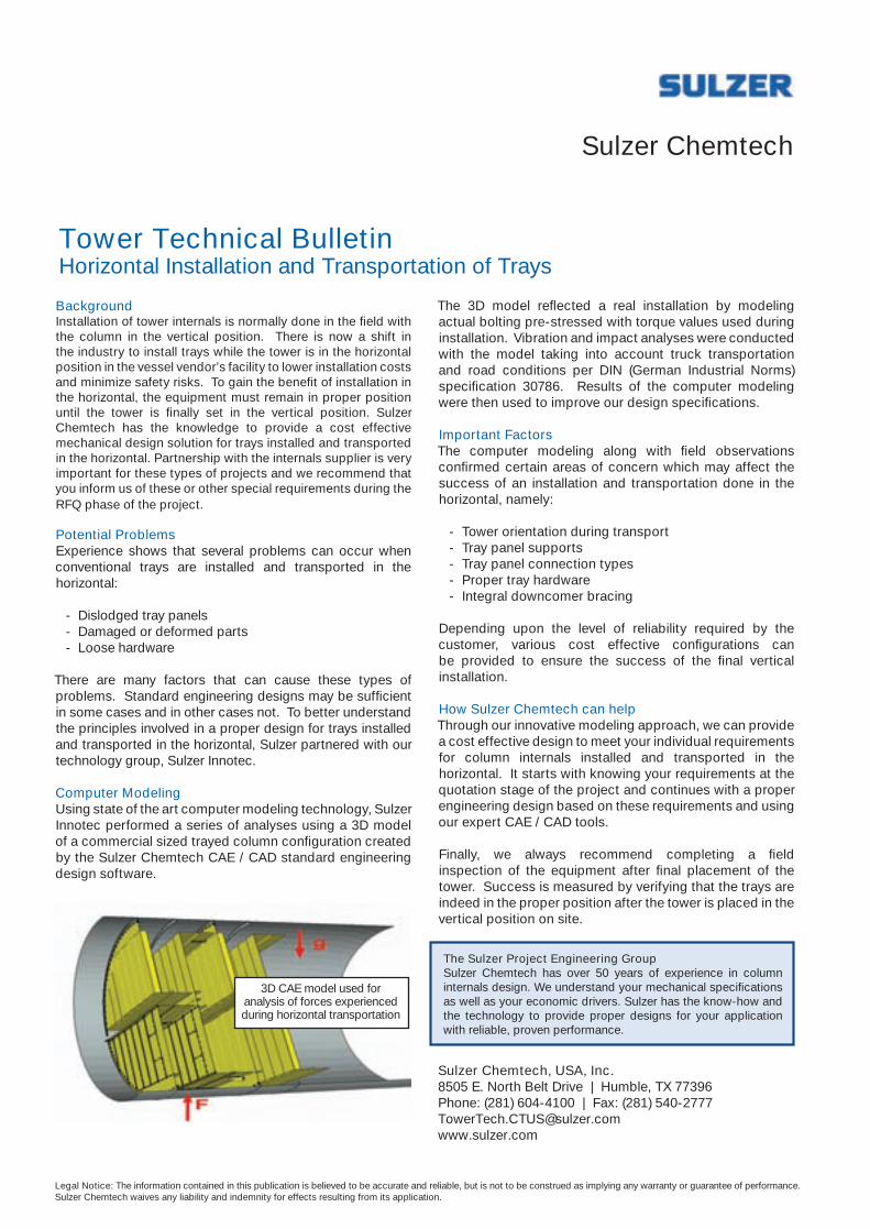
Background Installation of tower internals is normally done in the field with the column in the vertical position. There is now a shift in the industry to install trays while the tower is in the horizontal position in the vessel vendor’s facility to lower installation costs and minimize safety risks. To gain the benefit of installation in the horizontal, the equipment must remain in proper position until the tower is finally set in the vertical position. Sulzer Chemtech has the knowledge to provide a cost effective mechanical design solution for trays installed and transported in the horizontal. Partnership with the internals supplier is very important for these types of projects and we recommend that you inform us of these or other special requirements during the RFQ phase of the project.
Potential ProblemsExperience shows that several problems can occur when conventional trays are installed and transported in the horizontal:
- Dislodged tray panels - Damaged or deformed parts - Loose hardware
There are many factors that can cause these types of problems. Standard engineering designs may be sufficient in some cases and in other cases not. To better understand the principles involved in a proper design for trays installed and transported in the horizontal, Sulzer partnered with our technology group, Sulzer Innotec.
Computer ModelingUsing state of the art computer modeling technology, Sulzer Innotec performed a series of analyses using a 3D model of a commercial sized trayed column configuration created by the Sulzer Chemtech CAE / CAD standard engineering design software.
Sulzer Chemtech
Tower Technical Bulletin Horizontal Installation and Transportation of Trays
The 3D model reflected a real installation by modeling actual bolting pre-stressed with torque values used during installation. Vibration and impact analyses were conducted with the model taking into account truck transportation and road conditions per DIN (German Industrial Norms) specification 30786. Results of the computer modeling were then used to improve our design specifications.
Important FactorsThe computer modeling along with field observations confirmed certain areas of concern which may affect the success of an installation and transportation done in the horizontal, namely:
- Tower orientation during transport - Tray panel supports - Tray panel connection types - Proper tray hardware - Integral downcomer bracing
Depending upon the level of reliability required by the customer, various cost effective configurations can be provided to ensure the success of the final vertical installation.
How Sulzer Chemtech can helpThrough our innovative modeling approach, we can provide a cost effective design to meet your individual requirements for column internals installed and transported in the horizontal. It starts with knowing your requirements at the quotation stage of the project and continues with a proper engineering design based on these requirements and using our expert CAE / CAD tools.
Finally, we always recommend completing a field inspection of the equipment after final placement of the tower. Success is measured by verifying that the trays are indeed in the proper position after the tower is placed in the vertical position on site.
Sulzer Chemtech, USA, Inc. 8505 E. North Belt Drive | Humble, TX 77396 Phone: (281) 604-4100 | Fax: (281) 540-2777 [email protected] www.sulzer.com
Legal Notice: The information contained in this publication is believed to be accurate and reliable, but is not to be construed as implying any warranty or guarantee of performance. Sulzer Chemtech waives any liability and indemnity for effects resulting from its application.
The Sulzer Project Engineering GroupSulzer Chemtech has over 50 years of experience in column internals design. We understand your mechanical specifications as well as your economic drivers. Sulzer has the know-how and the technology to provide proper designs for your application with reliable, proven performance.
3D CAE model used for analysis of forces experienced during horizontal transportation
sulzer.indd 1 27/02/2013 10:21
Cracking hydrocarbon feedstock with a heavy tail
Cracking furnaces are the heart of the ethylene plant. These furnaces convert hydrocarbon
feedstock into ethylene, propylene and other cracked gas products by thermal cracking in the presence of steam. Typical examples of hydro-carbon feeds are ethane, propane, butanes, naphthas, kerosenes, and heavy atmospheric and vacuum gas oils.
It could also be economical to crack low-quality feedstock with a heavy tail. This is a feedstock with a fraction that vaporises at a much higher temperature compared to the rest of the feedstock. Sometimes the fraction is not even vaporisable. Examples of such components are tar-like material, solid particles and the residuum of high-boiling fractions.
If a feedstock with a heavy tail is cracked in a cracking furnace, the heavy tail causes fouling in the convection section, radiant section and the transfer line exchangers. This fouling results in a short on-stream time and an uneconomi-cal operation.
However, the low-quality feed-stock can be cracked without fouling issues if the heavy tail is separated out at a suitable location in the convection section. Consequently, the heavy tail bypasses the remain-ing non-fouling part of the cracking furnace. Special attention has to be given to effectively control the sepa-ration of the heavy tail, because the operating parameters often have a limited flexibility.
Steam crackingSteam cracking is a process for the thermal conversion of hydrocarbon
The introduction of a vapour/liquid separation step allows for the efficient removal of a heavy tail from the furnace convection section
Johan van der eiJkTechnip
feedstock into ethylene, propylene and other cracked gas products by thermal cracking in the presence of steam. Various types of feedstock are used for steam cracking, such as ethane, propane, butanes, straight-run refinery fractions (naphtha, kerosene, atmospheric gas oil and vacuum gas oil) and hydrotreated feedstock (HVGO and hydrowax). The common denomi-nator among these different feedstock types is that the feedstock is a distilled product. This means that the feedstock is clean with no heavy ends (in the form of residue, tar, solid particles or very high-boil-ing fractions) present.
Nowadays, there is an increasing interest among ethylene producers to process natural gas condensates. These are basically unrefined hydrocarbons that are obtained as a byproduct from natural gas production. As these condensates have a wide boiling range, they are not directly suitable as motor fuel. This implies that their price level is lower than that of straight-run or hydrotreated feedstock and explains their popularity as petro-chemical feedstock.
The condensates available on the market originate from a wide vari-ety of sources, and so vary in their qualities and price levels. Some of them are directly suitable as cracker feedstock, but others contain heavy ends or impurities, which have adverse effects on the run length of the cracking furnace. The heavy tail and/or impurities may cause increased fouling in the following furnace parts:• The convection section, due to the formation of deposits
• The radiant section, due to increased catalytic coking activity caused by the presence of metals• Transfer line exchangers, due to increased tar formation.
On-line removal of the heavy tail inside the cracking furnace makes it feasible to crack low-quality and low-cost feedstock without expen-sive off-site pretreatment steps.
Process descriptionIn the convection section of a crack-ing furnace, heat is recovered from the hot flue gases leaving the radi-ant section where the actual steam cracking takes place. The recovered heat is used for high-pressure steam generation, and for preheat-ing the feedstock and process steam. In the case of liquid feed-stock, vaporisation takes place in the convection section.
An innovation concerns the process for the removal of the heavy tail from the furnace convec-tion section by the introduction of a vapour/liquid separation step at a temperature where the mixture of feed and process steam is not yet fully vaporised and the heavy tail is still present in the liquid phase. As the amount of heavy tail is very small, a high vaporisation degree (in the order of 97–99.5%) is required as an operating point for the separator.
Having the correct operating temperature is crucial. A too low temperature implies a loss of valua-ble feedstock, whereas a too high temperature causes a slip of heavy tail to the downstream furnace sections with subsequent run length problems. Part of the inno-vation was to develop a scheme for
www.eptq.com Processing Shale Feedstocks 2013 29
technip.indd 1 25/02/2013 19:36
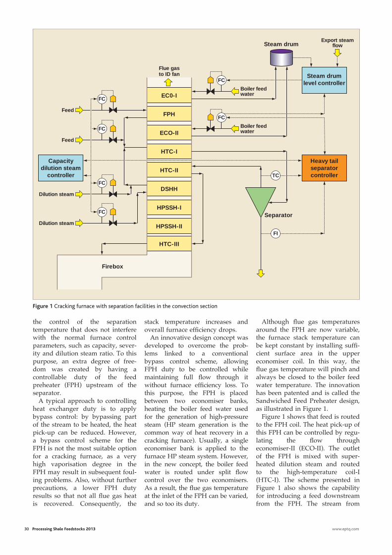
30 Processing Shale Feedstocks 2013 www.eptq.com
Although fl ue gas temperatures around the FPH are now variable, the furnace stack temperature can be kept constant by installing suffi -cient surface area in the upper economiser coil. In this way, the fl ue gas temperature will pinch and always be closed to the boiler feed water temperature. The innovation has been patented and is called the Sandwiched Feed Preheater design, as illustrated in Figure 1.
Figure 1 shows that feed is routed to the FPH coil. The heat pick-up of this FPH can be controlled by regu-lating the fl ow through economiser-II (ECO-II). The outlet of the FPH is mixed with super-heated dilution steam and routed to the high-temperature coil-I (HTC-I). The scheme presented in Figure 1 also shows the capability for introducing a feed downstream from the FPH. The stream from
the control of the separation temperature that does not interfere with the normal furnace control parameters, such as capacity, sever-ity and dilution steam ratio. To this purpose, an extra degree of free-dom was created by having a controllable duty of the feed preheater (FPH) upstream of the separator.
A typical approach to controlling heat exchanger duty is to apply bypass control: by bypassing part of the stream to be heated, the heat pick-up can be reduced. However, a bypass control scheme for the FPH is not the most suitable option for a cracking furnace, as a very high vaporisation degree in the FPH may result in subsequent foul-ing problems. Also, without further precautions, a lower FPH duty results so that not all fl ue gas heat is recovered. Consequently, the
stack temperature increases and overall furnace effi ciency drops.
An innovative design concept was developed to overcome the prob-lems linked to a conventional bypass control scheme, allowing FPH duty to be controlled while maintaining full fl ow through it without furnace effi ciency loss. To this purpose, the FPH is placed between two economiser banks, heating the boiler feed water used for the generation of high-pressure steam (HP steam generation is the common way of heat recovery in a cracking furnace). Usually, a single economiser bank is applied to the furnace HP steam system. However, in the new concept, the boiler feed water is routed under split fl ow control over the two economisers. As a result, the fl ue gas temperature at the inlet of the FPH can be varied, and so too its duty.
EC0-I
FPH
ECO-II
HTC-I
HTC-II
DSHH
HPSSH-I
HPSSH-II
HTC-III
Firebox
Flue gas to ID fan
FC
Feed
FC
Boiler feed water
Export steam flow
FC
Boiler feed waterFC
Feed
FC
Dilution steam
FC
Dilution steam
Capacity dilution steam
controller
Steam drum
Steam drum level controller
Heavy tail separator controllerTC
FI
Separator
Figure 1 Cracking furnace with separation facilities in the convection section
technip.indd 2 25/02/2013 19:36
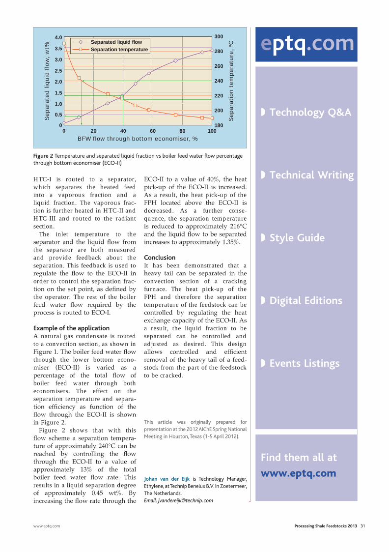
www.eptq.com Processing Shale Feedstocks 2013 31
HTC-I is routed to a separator, which separates the heated feed into a vaporous fraction and a liquid fraction. The vaporous frac-tion is further heated in HTC-II and HTC-III and routed to the radiant section.
The inlet temperature to the separator and the liquid flow from the separator are both measured and provide feedback about the separation. This feedback is used to regulate the flow to the ECO-II in order to control the separation frac-tion on the set point, as defined by the operator. The rest of the boiler feed water flow required by the process is routed to ECO-I.
Example of the applicationA natural gas condensate is routed to a convection section, as shown in Figure 1. The boiler feed water flow through the lower bottom econo-miser (ECO-II) is varied as a percentage of the total flow of boiler feed water through both economisers. The effect on the separation temperature and separa-tion efficiency as function of the flow through the ECO-II is shown in Figure 2.
Figure 2 shows that with this flow scheme a separation tempera-ture of approximately 240°C can be reached by controlling the flow through the ECO-II to a value of approximately 13% of the total boiler feed water flow rate. This results in a liquid separation degree of approximately 0.45 wt%. By increasing the flow rate through the
ECO-II to a value of 40%, the heat pick-up of the ECO-II is increased. As a result, the heat pick-up of the FPH located above the ECO-II is decreased. As a further conse-quence, the separation temperature is reduced to approximately 216°C and the liquid flow to be separated increases to approximately 1.35%.
ConclusionIt has been demonstrated that a heavy tail can be separated in the convection section of a cracking furnace. The heat pick-up of the FPH and therefore the separation temperature of the feedstock can be controlled by regulating the heat exchange capacity of the ECO-II. As a result, the liquid fraction to be separated can be controlled and adjusted as desired. This design allows controlled and efficient removal of the heavy tail of a feed-stock from the part of the feedstock to be cracked.
This article was originally prepared for presentation at the 2012 AIChE Spring National Meeting in Houston, Texas (1-5 April 2012).
Johan van der Eijk is Technology Manager, Ethylene, at Technip Benelux B.V. in Zoetermeer, The Netherlands. Email: [email protected]
3.0
4.0
3.5
2.5
2.0
1.5
1.0
0.5
0 20 40 60 80 100
Separa
ted liq
uid
flo
w,
wt%
BFW flow through bottom economiser, %
0
Separation temperatureSeparated liquid flow
280
300
260
240
220
200
Separa
tion t
em
pera
ture
, ºC
180
Figure 2 Temperature and separated liquid fraction vs boiler feed water flow percentage through bottom economiser (ECO-II)
www.eptq.com Sour & Heavy 2012 21
Canadian bitumen blends in the 18-20 °API gravity range.
Heavy Venezuelan crudes have been processed since the mid 1980s in high blend percentages by only a few US refiners. In nearly all cases, the CDU/VDUs did not meet design capacity, product yields or reliability. In some instances, none of these goals were achieved, with the units requiring major revamps just to meet their original design basis. Today, Venezuelan crudes are increasingly going to India and the Far East because they are seen as low-cost alternatives to Middle East and West African crudes. In most instances, the lessons learned in the US have not been incorpo-rated in the CDU/VDU designs. Few major engineering and construction companies have designed units for Orinoco bitumen blends, and the ones that have often repeat the same mistakes on future designs because they rarely perform rigorous post start-up audits and almost never look at unit perform-ance one to four years after start-up when reliability problems show up.
ConclusionsLessons learned by US refiners processing heavy Venezuelan crudes and Canadian upgraders processing bitumen should be applied to new projects that will process increasing amounts of
opportunity crudes. These units should not be designed with conventional practices used for light and medium crudes; other-wise, run length will be short, product yields and quality poor, and maintenance costs high. Opportunity crude properties are very different and design require-ments will raise initial costs. These higher initial costs will pay out over the life of the project through an increased VGO product yield, lower maintenance costs, fewer VGO contaminants and a longer run length between decokings.
Scott Golden is a Chemical Engineer with Process Consulting Services, Inc, in Houston, Texas. He specialises in front-end process engineering for refinery unit revamps and has authored more than 100 technical papers on revamping and troubleshooting refinery process units. Email: [email protected] Tony Barletta is a Chemical Engineer with Process Consulting Services, Inc., in Houston, Texas. His primary responsibilities are conceptual process design and process design packages for large capital revamps. Email: [email protected] Steve White is a Chemical Engineer with Process Consulting Services, Inc, in Houston, Texas. He has more than 30 years of process design experience for refinery revamps and grassroots units. Email: [email protected]
Figure 3 Severe wash zone coking
eptq.com
◗ Technology Q&A
◗ Technical Writing
◗ Style Guide
◗ Digital Editions
◗ Events Listings
Find them all at
www.eptq.com
technip.indd 3 26/02/2013 13:17

Naphtha catalytic cracking for propylene production
Ethylene is produced through steam cracking of hydrocarbon feedstock (for example, ethane,
naphtha and gas oils) derived during conventional and unconven-tional natural gas production and from refinery crude oil processing. Ethane and natural gas liquids (NGLs) are derived from natural gas and heavy liquid feedstocks of naphtha, and gas oils from crude. Naphtha is the predominant feed-stock on a global basis, including straight-run naphthas (SRN) from refinery crude units and naphtha derived from condensates during natural gas production. While ethylene is the world’s primary petrochemical building block, propylene is second in importance only to ethylene as a raw material building block. Traditionally, propylene has been obtained as a byproduct from steam cracking naphtha and gas oils to produce ethylene, and from gasoline-pro-ducing refinery fluid catalytic cracking (FCC) processes.
Global ethylene and propylene demand has recovered from the 2008-2009 recession, and longer term demand expansion is expected. Propylene demand was increasing faster than ethylene demand before the recession, which is not the case today. Up to 2007, global propylene demand was increasing annually at 6.0%, while today it is expected to increase by 3.6% on average for the next several years, according to analysis from Nexant ChemSystems. Even at these lower demand predictions, there is expected to be shortages in propylene supply.
Nonetheless, future global
Investment in on-purpose propylene production technology based on naphtha-based feedstock is taking on various process configurations
ChrIstophEr DEanHigh Olefins FCC Technology Services
ethylene demand still determines steam cracking capacity and is expected to be met in each region, as shown in the graphic developed by CMAI in Figure 1.
Figure 1 reflects ethylene capacity additions according to CMAI’s research. Asia is the fastest-growing light olefin market and uses naph-tha as its feedstock. Existing Middle Eastern steam crackers as well as those being built use primarily ethane-based feedstock for produc-ing ethylene. The North American units are emerging due to access to cheap shale-based ethane feedstock (less than 22.50 cents per gallon as of mid-January 2013), and several will come on line after 2016.1 These bargain prices for US-based ethane and natural gas feedstock are expected to be sustained beyond
2016 relative to similar feedstocks in Asia and elsewhere. However, in spite of these competitive prices, it is well known that ethane-based steam crackers produce very little propylene relative to naphtha and gas oil-based steam crackers, which is why the onus is on investing in on-purpose propylene production (OPP) technology.
Steam cracking heavy feedstocks of naphtha and gas oils produces about 60% of the global propylene demand, while 30% comes from traditional FCC units that produce gasoline. High propylene yields from steam cracking are ultimately produced through various recycling and operating severities of these heavy feeds or non-ethane-based feedstocks. Steam cracking produces more pounds of ethylene to pounds of propylene on a weight basis. Table 1 is based on general industry knowledge and shows the typical ethylene and propylene yield in weight percentage for a pound of feed as it varies for a particular feedstock. The propylene/ethylene (P/E) ratio indicates the selectivity of the cracking condi-tions to produce propylene.
The P/E ratio is one way of tracking global propylene demand in relationship to ethylene demand. This ratio also indicates which
www.eptq.com Processing Shale Feedstocks 2013 33
Other10%
North America 10%
Middle East 21%
Indian subcontinent 14%
Northeast Asia excl. China 3%
Southeast Asia 8%
China 34%
Figure 1 2012-2016 ethylene capacity additions
Feedstock Ethylene, wt% propylene, wt% p/E Ethane 80 3 0.04 (0.0375)Propane 44 15 0.34Naphtha 30 16 0.53Gas oil 23 15 0.65
typical light olefin yields for steam cracking
table 1
dean.indd 1 25/02/2013 19:42
34 Processing Shale Feedstocks 2013 www.eptq.com
feedstocks of butylenes and aromat-ics as those from the HOFCCs.
As mentioned previously, the second significant source of propyl-ene production is in the form of a byproduct from existing FCC processes primarily designed for producing gasoline and other fuels. These processes have been modified by operating at higher severities and different catalysts to produce high levels of propylene and other light olefins and aromatics at the expense of gasoline and other liquid fuels. In the US, there is a current and expected future slump in gasoline demand with an increase in diesel demand, which reduces the FCC unit’s effectiveness for maximising propylene production. As a result, significant propylene production increases from these modified FCC units will not meet the expected propylene demand.
Catalytically cracking naphtha The HOFCC processes and related technologies will be the future OPP drivers for petrochemicals. Future incremental propylene supply will come from these enhanced FCC processes that target light olefin production and heavier petrochem-ical feedstocks, such as aromatics, instead of the traditional gasoline product. These future processes will not just be heavy oil feedstock, but will also include FCC processes to catalytically crack naphtha.
As previously inferred, HOFCC is a group of proprietary FCC processes targeting light olefin production instead of gasoline product from traditional FCC process technology. These HOFCC processes utilise traditional FCC technology with some modifica-tions. Operating severities and different catalysts are used for producing and maximising propyl-ene and other light olefin products. These HOFCC processes use heav-ier treated feedstocks from crude oil, gas oils or resids, similar to gasoline FCC feedstocks. These units produce more light products and will minimise gasoline produced for the gasoline fuel blending pool, which is why HOFCC units are essentially petro-chemical feedstock units. They are
production propylene processes are needed to meet this demand.
Increasing P/E ratios beyond 1.0The P/E ratios of 0.65 and 0.53 for gas oil and naphtha, respectively, indicate that heavier feeds produce a higher ratio of propylene to ethyl-ene. It is important to note that globally gas oil steam cracking is being reduced due to these heavier feedstocks being diverted to meet higher product demand for diesel and other fuels.
In the pre-recession period up to 2007, it was estimated that the global propylene demand required a P/E ratio of greater than 0.85. Today, this demand is still expected to be higher than those P/E ratios produced by cracking naphtha and even gas oil feedstocks. Therefore, in order for OPP proposals to mate-rialise, they have to be better than the P/E ratios of 0.53 to 0.65 for naphtha and gas oil steam cracking, respectively. Existing FCC and the new high olefin FCC (HOFCC) process will produce P/E ratios from 1.0 to greater than 2.0 to meet this propylene demand.
The well-documented shift in ethane production from multiple shale plays in North America has placed steam crackers utilising heavy feeds of naphtha and gas oil at a competitive disadvantage in spite of their high propylene production capacity (P/E between 0.53 to 0.65) relative to ethane-based steam crackers (P/E only 0.04). Since steam cracking is determined by ethylene demand and the shift to gas feedstocks from liquids, global propylene demand cannot be met from the expected increase in steam cracking production. This is particu-larly the case with the North American propylene market should all the announced ethane-based steam crackers (approximately seven) go online by 2017.
As ethane cracking capacity increases, propylene production decreases significantly and is reflected in the increased pricing ratio of propylene to ethylene. Besides, CMAI, Nexant and others predict that propylene pricing will remain higher than ethylene pricing. This is especially true in the US,
where there was historically an abundant propylene supply due to significant refining capacity. However, refining capacity is decreasing and what remains is shifting from gasoline to more diesel production, which reduces propyl-ene production. Since ethylene demand is expanding proportionally faster to propylene, naphtha steam crackers cannot meet the expected incremental demand for propylene. Other OPP technology will therefore be developed.
High-severity FCC processing (HS-FCC) produces high yields of light olefins and reduces liquid fuels. Existing FCC units can oper-ate at more severe conditions that will increase light olefin yields but still produce significant amounts of fuels (gasoline). The HS-FCC term is somewhat confusing due to licensing issues and for processes that specifically produce petro-chemical feedstocks. These FCC processes produce light olefins and highly aromatic content liquid products that are used for petro-chemical unit feedstocks. To clarify, the term HOFCC will be used to differentiate those FCC processes that are only petrochemical product based. In this instance, HS-FCC refers to HOFCC-type processes.
CMAI research indicates OPP capacity will increase from 13% to 20% over the next several years and future demand for non-steam cracking propylene sources will continue. Propane dehydrogenation (PDH) processes currently show the largest increase for meeting this propylene demand. Most of these processes besides the HOFCC are being installed by chemical compa-nies and not refiners to meet their propylene feedstock requirements.
Other OPP technology for propylene production, including metathesis of ethylene and buty-lenes, and olefinic naphtha cracking, require integration with a steam cracker or other processes that produce olefins as byproducts. In addition, these processes cannot produce significant propylene yields at cost advantages compared to HOFCC processes. These processes also cannot produce the additional byproduct petrochemical
dean.indd 2 25/02/2013 19:42
1 Hear Daniele Ferrari, CEO Versalis on how to boost European competitiveness in a global market
2 Benefi t from our Speed Networking and create long lasting business relations
3 Learn from Fernando Iturrieta, CEPSA the best strategies to invest in emerging markets
4 Understand how to improve your energy effi ciency to reduce overall costs through our interactive workshop
5 Explore alternative routes to production in a changing feedstock market with Chevron and Braskem
REASONS TO ATTEND1 Hear Daniele Ferrari, CEO
Versalis on how to boost European competitiveness in a global market
2 Benefi t from our Speed Networking and create long lasting business relations
3 Learn from Fernando Iturrieta, CEPSA the best strategies to invest in emerging markets
4 Understand how to improve your energy effi ciency to reduce overall costs through our interactive workshop
5 Explore alternative routes to production in a changing feedstock market with Chevron and Braskem
REASONS TO ATTEND
11 – 13 June 2013
MUNICH, GERMANYwww.wraconferences.com/gpc
GLOBAL PETROCHEMICALS CONFERENCE10th AnnualSTRATEGY & OPPORTUNITY FOR PETROCHEMICAL PRODUCERS & THEIR PARTNERS
Sponsor & Partners Supporting Associations: Media Partners:
BOOK
BEFORE
28 TH MARCH
TO SAVE £300
2FOR1
PETCHEM
PRODUCER
BEFORE 28 TH MARCH
CONFERENCE DAY ONE:
MAINTAINING EUROPE’S
COMPETITIVENESS ON A GLOBAL STAGE
11 June 2013
CONFERENCE DAY TWO:
FEEDSTOCKS12 June 2013
WORKSHOPS:IMPROVING ENERGY
EFFICIENCY AND ENHANCING
CHEMICAL PROCESSES13 June 2013
Daniele Ferrari, Chief Executive Offi cer, Versalis
Fernando Iturrieta, Chief Executive Offi cer, CEPSA Quimica
Massimo Covezzi, Senior Vice President, R&D, LyondellBasell
Sameer Al-Humaidan, Vice President, Technical Affairs, TASNEE
Petri Lehmus, Vice President, Research & Development, Neste Oil Corporation
Benny Mermans, Europe & Africa General Manager, Chevron
Pierre de Kettenis, Executive Director, CEFIC
GLOBAL SPEAKER FACULTY
gpc.indd 1 28/02/2013 11:32
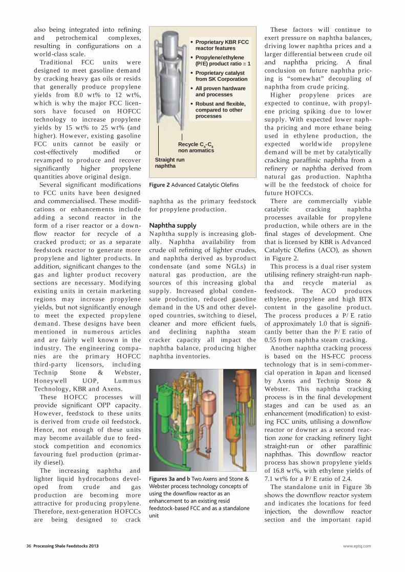
36 Processing Shale Feedstocks 2013 www.eptq.com
also being integrated into refi ning and petrochemical complexes, resulting in confi gurations on a world-class scale.
Traditional FCC units were designed to meet gasoline demand by cracking heavy gas oils or resids that generally produce propylene yields from 8.0 wt% to 12 wt%, which is why the major FCC licen-sors have focused on HOFCC technology to increase propylene yields by 15 wt% to 25 wt% (and higher). However, existing gasoline FCC units cannot be easily or cost-effectively modifi ed or revamped to produce and recover signifi cantly higher propylene quantities above original design.
Several signifi cant modifi cations to FCC units have been designed and commercialised. These modifi -cations or enhancements include adding a second reactor in the form of a riser reactor or a down-fl ow reactor for recycle of a cracked product; or as a separate feedstock reactor to generate more propylene and lighter products. In addition, signifi cant changes to the gas and lighter product recovery sections are necessary. Modifying existing units in certain marketing regions may increase propylene yields, but not signifi cantly enough to meet the expected propylene demand. These designs have been mentioned in numerous articles and are fairly well known in the industry. The engineering compa-nies are the primary HOFCC third-party licensors, including Technip Stone & Webster, Honeywell UOP, Lummus Technology, KBR and Axens.
These HOFCC processes will provide signifi cant OPP capacity. However, feedstock to these units is derived from crude oil feedstock. Hence, not enough of these units may become available due to feed-stock competition and economics favouring fuel production (primar-ily diesel).
The increasing naphtha and lighter liquid hydrocarbons devel-oped from crude and gas production are becoming more attractive for producing propylene. Therefore, next-generation HOFCCs are being designed to crack
naphtha as the primary feedstock for propylene production.
Naphtha supply Naphtha supply is increasing glob-ally. Naphtha availability from crude oil refi ning of lighter crudes, and naphtha derived as byproduct condensate (and some NGLs) in natural gas production, are the sources of this increasing global supply. Increased global conden-sate production, reduced gasoline demand in the US and other devel-oped countries, switching to diesel, cleaner and more effi cient fuels, and declining naphtha steam cracker capacity all impact the naphtha balance, producing higher naphtha inventories.
These factors will continue to exert pressure on naphtha balances, driving lower naphtha prices and a larger differential between crude oil and naphtha pricing. A fi nal conclusion on future naphtha pric-ing is “somewhat” decoupling of naphtha from crude pricing.
Higher propylene prices are expected to continue, with propyl-ene pricing spiking due to lower supply. With expected lower naph-tha pricing and more ethane being used in ethylene production, the expected worldwide propylene demand will be met by catalytically cracking paraffi nic naphtha from a refi nery or naphtha derived from natural gas production. Naphtha will be the feedstock of choice for future HOFCCs.
There are commercially viable catalytic cracking naphtha processes available for propylene production, while others are in the fi nal stages of development. One that is licensed by KBR is Advanced Catalytic Olefi ns (ACO), as shown in Figure 2.
This process is a dual riser system utilising refi nery straight-run naph-tha and recycle material as feedstock. The ACO produces ethylene, propylene and high BTX content in the gasoline product. The process produces a P/E ratio of approximately 1.0 that is signifi -cantly better than the P/E ratio of 0.55 from naphtha steam cracking.
Another naphtha cracking process is based on the HS-FCC process technology that is in semi-commer-cial operation in Japan and licensed by Axens and Technip Stone & Webster. This naphtha cracking process is in the fi nal development stages and can be used as an enhancement (modifi cation) to exist-ing FCC units, utilising a downfl ow reactor or downer as a second reac-tion zone for cracking refi nery light straight-run or other paraffi nic naphthas. This downfl ow reactor process has shown propylene yields of 16.8 wt%, with ethylene yields of 7.1 wt% for a P/E ratio of 2.4.
The standalone unit in Figure 3b shows the downfl ow reactor system and indicates the locations for feed injection, the downfl ow reactor section and the important rapid
Proprietary KBR FCC reactor features
Propylene/ethylene (P/E) product ratio ≅ 1
Proprietary catalyst from SK Corporation
All proven hardware and processes
Robust and flexible, compared to other processes
Straight run naphtha
Recycle C4-C6 non aromatics
Figure 2 Advanced Catalytic Olefi ns
Figures 3a and b Two Axens and Stone & Webster process technology concepts of using the downfl ow reactor as an enhancement to an existing resid feedstock-based FCC and as a standalone unit
dean.indd 3 25/02/2013 19:42
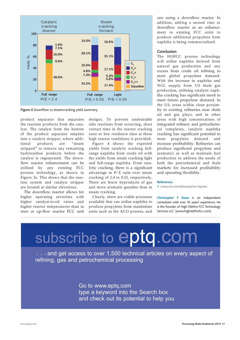
designs. To prevent undesirable side reactions from occurring, short contact time in the reactor cracking zone or low residence time at these high reactor conditions is provided.
Figure 4 shows the expected yields from catalytic cracking full-range naphtha from crude oil with the yields from steam cracking light and full-range naphtha. From cata-lytic cracking, there is a significant advantage in P/E ratio over steam cracking of 2.4 to 0.55, respectively. There are fewer byproducts of gas and more aromatic gasoline than in steam cracking.
Clearly, there are viable processes available that can utilise naphtha to produce propylene from standalone units such as the ACO process, and
www.eptq.com Processing Shale Feedstocks 2013 37
product separator that separates the reaction products from the cata-lyst. The catalyst from the bottom of the product separator empties into a catalyst stripper, where addi-tional products are “steam stripped” to remove any remaining hydrocarbon products before the catalyst is regenerated. The down-flow reactor enhancement can be utilised by any existing FCC process technology, as shown in Figure 3a. This shows that the reac-tion system and catalyst stripper are located at similar elevations.
The downflow reactor allows for higher operating severities with higher catalyst-to-oil ratios and higher reactor temperatures than in riser or up-flow reactor FCC unit
one using a downflow reactor. In addition, adding a second riser or downflow reactor as an enhance-ment to existing FCC units to produce additional propylene from naphtha is being commercialised.
Conclusion The HOFCC process technology will utilise naphtha derived from natural gas production and any excess from crude oil refining to meet global propylene demand. With the increase in naphtha and NGL supply from US shale gas production, utilising catalytic naph-tha cracking has significant merit to meet future propylene demand. In the US, areas within close proxim-ity to existing refineries near shale oil and gas plays, and in other areas with high concentrations of integrated refinery and petrochemi-cal complexes, catalytic naphtha cracking has significant potential to meet propylene demand and increase profitability. Refineries can produce significant propylene and aromatics as well as maintain fuel production to address the needs of both the petrochemical and fuels markets for increased profitability and operating flexibility.
References1 www.icis.com/about/price-reports
Christopher F Dean is an independent consultant with over 35 years’ experience. He is the founder of High Olefins FCC Technology Services LLC (www.higholefinsfcc.com).
60
100
80
40
2048.5%
24.2%
7.4%4.8%
15.5%
28.1%
14.5%
17.4%
5.6%5.3%
17.1%
31.1%
16.5%
8.6%
16.8%
7.1%1.8%
Full range
Yie
ld,
%
P/E = 2.4Full range
P/E = 0.55Light
P/E = 0.55
0
Catalytic cracking downer
Steam cracking furnace
C1
C2=C3=C4=C4==Gasoline
Figure 4 Downflow vs steamcracking yield summary
...and get access to over 1,500 technical articles on every aspect of refining, gas and petrochemical processing
Go to www.eptq.comtype a keyword into the Search boxand check out its potential to help you
subscribe to eptq.com
dean.indd 4 28/02/2013 12:01
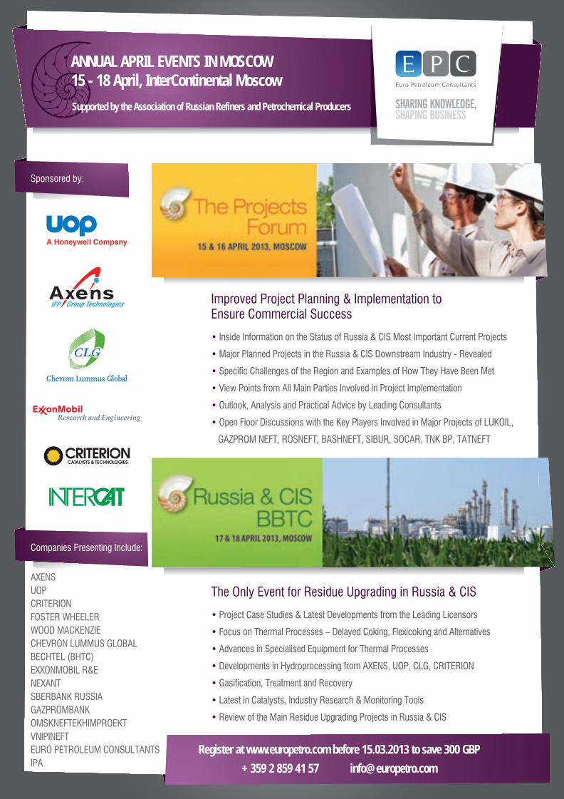
Improved Project Planning & Implementation toEnsure Commercial Success
• Inside Information on the Status of Russia & CIS Most Important Current Projects
• Major Planned Projects in the Russia & CIS Downstream Industry - Revealed
• Specific Challenges of the Region and Examples of How They Have Been Met
• View Points from All Main Parties Involved in Project Implementation
• Outlook, Analysis and Practical Advice by Leading Consultants
• Open Floor Discussions with the Key Players Involved in Major Projects of LUKOIL,
GAZPROM NEFT, ROSNEFT, BASHNEFT, SIBUR, SOCAR, TNK BP, TATNEFT
The Only Event for Residue Upgrading in Russia & CIS
• Project Case Studies & Latest Developments from the Leading Licensors
• Focus on Thermal Processes – Delayed Coking, Flexicoking and Alternatives
• Advances in Specialised Equipment for Thermal Processes
• Developments in Hydroprocessing from AXENS, UOP, CLG, CRITERION
• Gasification, Treatment and Recovery
• Latest in Catalysts, Industry Research & Monitoring Tools
• Review of the Main Residue Upgrading Projects in Russia & CIS
Sponsored by:
Companies Presenting Include:
ANNUAL APRIL EVENTS IN MOSCOW15 - 18 April, InterContinental Moscow
Register at www.europetro.com before 15.03.2013 to save 300 GBP
+359 2 859 41 57 [email protected]
AXENS
UOP
CRITERION
FOSTER WHEELER
WOOD MACKENZIE
CHEVRON LUMMUS GLOBAL
BECHTEL (BHTC)
EXXONMOBIL R&E
NEXANT
SBERBANK RUSSIA
GAZPROMBANK
OMSKNEFTEKHIMPROEKT
VNIPINEFT
EURO PETROLEUM CONSULTANTS
IPA
Supported by the Association of Russian Refiners and Petrochemical Producers
epc.indd 1 25/02/2013 15:00
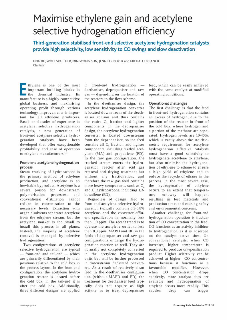
Maximise ethylene gain and acetylene selective hydrogenation efficiency
E thylene is one of the most important building blocks in the chemical industry. Its
manufacture is a highly competitive global business, and maximising operating profit through various technology improvements is impor-tant for all ethylene producers. Based on decades of experience in acetylene selective hydrogenation catalysis, a new generation of front-end acetylene selective hydro-genation catalysts have been developed that offer exceptionable profitability and ease of operation to ethylene manufacturers.1-4
Front-end acetylene hydrogenation process Steam cracking of hydrocarbons is the primary method of ethylene production, and acetylene is an inevitable byproduct. Acetylene is a severe poison for downstream polymerisation processes, and conventional distillation cannot reduce its concentration to the necessary levels. Extraction with organic solvents separates acetylene from the ethylene stream, but the acetylene market is too small to install this process in all plants. Instead, the majority of acetylene removal is managed by selective hydrogenation.
Two configurations of acetylene selective hydrogenation are typical — front-end and tail-end — which are primarily differentiated by their positions relative to the cold box in the process layout. In the front-end configuration, the acetylene hydro-genation reactor is located before the cold box; in the tail-end it is after the cold box. Additionally, three different designs are applied
Third-generation stabilised front-end selective acetylene hydrogenation catalysts provide high selectivity, low sensitivity to CO swings and slow deactivation
Ling Xu, WOLF SpaEThEr, MingyOng Sun, JEnniFEr BOyEr and MiChaEL urBanCiC Clariant
in front-end hydrogenation — deethaniser, depropaniser and raw gas — depending on the location of the reactors in the flow scheme.
In the deethaniser design, the acetylene hydrogenation converter is located downstream of the deeth-aniser column and thus contains the entire C2 fraction and lighter components. In the depropaniser design, the acetylene hydrogenation converter is located downstream from the depropaniser, so the feed contains all C3 fraction and lighter components, including methyl acet-ylene (MA) and propadiene (PD). In the raw gas configuration, the cracked stream enters the hydro-genation reactor after acid gas removal and drying treatment but without any fractionation, and therefore the raw gas feed contains more heavy components, such as C4 and C5 hydrocarbons, including 1,3-butadiene (BD).
Regardless of design, feed to front-end acetylene selective hydro-genation typically contains 0.3-0.8% acetylene, and the converter efflu-ent specification is normally less than 1.0 ppm. The recent trend is to operate the acetylene outlet to less than 0.3 ppm. MAPD and BD in the feeds of depropaniser and raw gas configurations undergo the hydro-genation reaction as well. They are normally not completely converted in the acetylene hydrogenation units but will be further processed in downstream dedicated convert-ers. As a result of relatively clean feed in the deethaniser configura-tion (without MAPD and BD), the treatment for deethaniser feed typi-cally does not require as high activity as to treat depropaniser
feed, which can be easily achieved with the same catalyst at modified operating conditions.
Operational challengesThe first challenge is that the feed in front-end hydrogenation contains an excess of hydrogen, due to the position of the reactor in front of the cold box, where hydrogen and a portion of the methane are sepa-rated. Hydrogen levels are 10-40%, which is vastly above the stoichio-metric requirement for acetylene hydrogenation. Effective catalysts must have a good selectivity to hydrogenate acetylene to ethylene, but also minimise the hydrogena-tion of ethylene to ethane to ensure a high yield of ethylene and to reduce the recycle of ethane in the process. In the most severe case, the hydrogenation of ethylene occurs to an extent that tempera-ture runaway will happen, resulting in lost materials and production time, and causing safety and environmental concerns.
Another challenge for front-end hydrogenation operation is fluctua-tion of CO concentration in the feed. CO functions as an activity inhibitor to hydrogenation as it is adsorbed on the catalyst active sites. On conventional catalysts, when CO increases, higher temperature is required to produce on-specification product. Higher selectivity can be achieved at higher CO concentra-tions because it functions as a favourable modifier. However, when CO concentration drops suddenly, more catalyst sites are available and hydrogenation of ethylene occurs more readily. This sudden drop can trigger
www.eptq.com Processing Shale Feedstocks 2013 39
clariANT.indd 1 25/02/2013 19:48
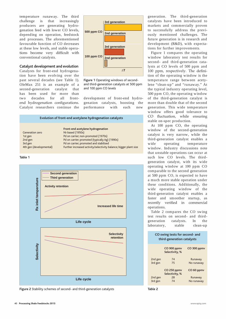
40 Processing Shale Feedstocks 2013 www.eptq.com
generation. The third-generation catalysts have been introduced to markets and commercially proven to successfully address the previ-ously mentioned challenges. The future generation is in research and development (R&D), with expecta-tions for further improvements.
Figure 1 compares the operating window laboratory test results for second- and third-generation cata-lysts at CO levels of 500 ppm and 100 ppm, respectively. The defini-tion of the operating window is the temperature range between acety-lene “clean-up” and “runaway.” At the typical industry operating level, 500 ppm CO, the operating window of the third-generation catalyst is more than double that of the second generation. This wide temperature window offers good tolerance to CO fluctuation, while ensuring stable on-spec production.
At 100 ppm CO, the operating window of the second-generation catalyst is very narrow, while the third-generation catalyst enables a wide operating temperature window. Industry discussions note that unstable operations can occur at such low CO levels. The third- generation catalyst, with its wide operating window at 100 ppm CO comparable to the second generation at 500 ppm CO, is expected to have a much more stable operation under these conditions. Additionally, the wide operating window of the third-generation catalyst enables a faster and smoother startup, as recently verified in commercial operations.
Table 2 compares the CO swing test results on second- and third-generation catalysts. In the laboratory, stable clean-up
temperature runaway. The third challenge is that increasingly producers are generating hydro-genation feed with lower CO levels, depending on operation, feedstock and processes. The aforementioned favourable function of CO decreases at these low levels, and stable opera-tions become very difficult with conventional catalysts.
Catalyst development and evolutionCatalysts for front-end hydrogena-tion have been evolving over the past several decades (see Table 1). OleMax 251 is an example of a second-generation catalyst that has been used for more than two decades for all front- end hydrogenation configurations. Catalyst researchers continue the
development of front-end hydro-genation catalysts, boosting the performance with each new
500 ppm CO 2nd generation
3rd generation
2nd generation
3rd generation
100 ppm CO
∆T
Rx
inle
t te
mp
erat
ure
Life cycle
Activity retention
Increased life time
Sel
ecti
vity
Life cycle
Selectivity retention
Third generationSecond generation
Figure 1 Operating windows of second- and third-generation catalysts at 500 ppm and 100 ppm CO levels
Figure 2 Stability schemes of second- and third-generation catalysts
Front-end acetylene hydrogenationGeneration zero Ni-based (1950s)1st gen Pd on carrier; non-promoted (1970s)2nd gen Pd on carrier; promoted (typically Ag) (1990s)3rd gen Pd on carrier; promoted and stabilised 4th gen (developmental) Further increased activity/selectivity balance; bigger plant size
Evolution of front-end acetylene hydrogenation catalysts
Table 1
CO 900 ppmv CO 300 ppmv Selectivity, %
2nd gen 74 Runaway3rd gen 75 No runaway
CO 250 ppmv CO 60 ppmv Selectivity, % 2nd gen 28 Runaway3rd gen 74 No runaway
CO swing tests for second- and third-generation catalysts
Table 2
clariANT.indd 2 26/02/2013 11:20
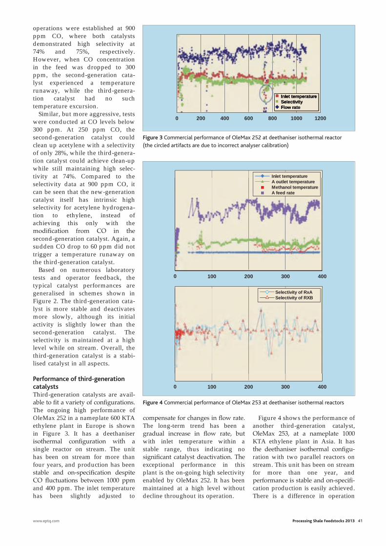
www.eptq.com Processing Shale Feedstocks 2013 41
operations were established at 900 ppm CO, where both catalysts demonstrated high selectivity at 74% and 75%, respectively. However, when CO concentration in the feed was dropped to 300 ppm, the second-generation cata-lyst experienced a temperature runaway, while the third-genera-tion catalyst had no such temperature excursion.
Similar, but more aggressive, tests were conducted at CO levels below 300 ppm. At 250 ppm CO, the second-generation catalyst could clean up acetylene with a selectivity of only 28%, while the third-genera-tion catalyst could achieve clean-up while still maintaining high selec-tivity at 74%. Compared to the selectivity data at 900 ppm CO, it can be seen that the new-generation catalyst itself has intrinsic high selectivity for acetylene hydrogena-tion to ethylene, instead of achieving this only with the modifi cation from CO in the second-generation catalyst. Again, a sudden CO drop to 60 ppm did not trigger a temperature runaway on the third-generation catalyst.
Based on numerous laboratory tests and operator feedback, the typical catalyst performances are generalised in schemes shown in Figure 2. The third-generation cata-lyst is more stable and deactivates more slowly, although its initial activity is slightly lower than the second-generation catalyst. The selectivity is maintained at a high level while on stream. Overall, the third-generation catalyst is a stabi-lised catalyst in all aspects.
Performance of third-generationcatalysts Third-generation catalysts are avail-able to fi t a variety of confi gurations. The ongoing high performance of OleMax 252 in a nameplate 600 KTA ethylene plant in Europe is shown in Figure 3. It has a deethaniser isothermal confi guration with a single reactor on stream. The unit has been on stream for more than four years, and production has been stable and on-specifi cation despite CO fl uctuations between 1000 ppm and 400 ppm. The inlet temperature has been slightly adjusted to
compensate for changes in fl ow rate. The long-term trend has been a gradual increase in fl ow rate, but with inlet temperature within a stable range, thus indicating no signifi cant catalyst deactivation. The exceptional performance in this plant is the on-going high selectivity enabled by OleMax 252. It has been maintained at a high level without decline throughout its operation.
Figure 4 shows the performance of another third-generation catalyst, OleMax 253, at a nameplate 1000 KTA ethylene plant in Asia. It has the deethaniser isothermal confi gu-ration with two parallel reactors on stream. This unit has been on stream for more than one year, and performance is stable and on-specifi -cation production is easily achieved. There is a difference in operation
2000 400 600 800 1000 1200
Inlet temperature
Flow rateSelectivityInlet temperature
Flow rateSelectivity
0 100 200 300 400
0 100 200 300 400
Selectivity of RxASelectivity of RXB
Methanol temperature
Inlet temperatureA outlet temperature
A feed rate
Figure 3 Commercial performance of OleMax 252 at deethaniser isothermal reactor (the circled artifacts are due to incorrect analyser calibration)
Figure 4 Commercial performance of OleMax 253 at deethaniser isothermal reactors
Table 2
clariANT.indd 3 25/02/2013 19:48
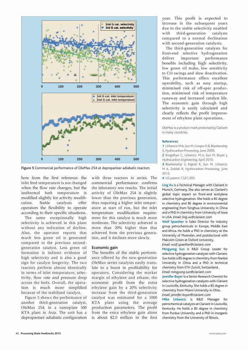
with three reactors in series. The commercial performance confi rms the laboratory test results. The initial activity of OleMax 254 is slightly lower than the previous generation, thus requiring a higher inlet temper-ature at start of run, but the inlet temperature modifi cation require-ment for this catalyst is much more moderate. The selectivity achieved is more than 20% higher than that achieved from the previous genera-tion, and it declines more slowly.
Economic gainThe benefi ts of the stable perform-ance offered by the new-generation OleMax series catalysts easily trans-late to a boost in profi tability for operators. Considering the market margin of ethylene and ethane, the economic profi t from the extra ethylene gain by a 20% selectivity increase from the third-generation catalyst was estimated for a 1000 KTA plant using the average production parameters. The profi t from the extra ethylene gain alone is about $2.0 million in the fi rst
42 Processing Shale Feedstocks 2013 www.eptq.com
here from the fi rst reference: the inlet feed temperature is not changed when the fl ow rate changes, but the isothermal bath temperature is modifi ed slightly for activity modifi -cation. Stable catalysts offer operators the fl exibility to operate according to their specifi c situations.
The same exceptionally high selectivity is achieved in this plant without any indication of decline. Also, the operator reports that much less green oil is generated compared to the previous second-generation catalyst. Less green oil formation is indirect evidence of high selectivity and is also a good sign for catalyst longevity. The two reactors perform almost identically in terms of inlet temperature, selec-tivity, fl ow rate and pressure drop across the beds. Overall, the opera-tion is much more simplifi ed because of the stabilised catalyst.
Figure 5 shows the performance of another third-generation catalyst, OleMax 254, in a nameplate 500 KTA plant in Asia. The unit has a depropaniser adiabatic confi guration
year. This profi t is expected to increase in the subsequent years due to the stable selectivity enabled with third-generation catalysts compared to a normal declination with second-generation catalysts.
The third-generation catalysts for front-end selective hydrogenation deliver important performance benefi ts including high selectivity, low green oil make, low sensitivity to CO swings and slow deactivation. This performance offers excellent operability, such as easy startup, minimised risk of off-spec produc-tion, minimised risk of temperature runaway and increased catalyst life. The economic gain through high selectivity is easily calculated and clearly refl ects the profi t improve-ment of ethylene plant operations.
OleMax is a product mark protected by Clariant in many countries.
References1 Urbancic M A, Sun M, Cooper D B, Blankenship S, Hydrocarbon Processing, June 2009.2 Ringelhan C, Urbancic M A, Sun M, Boyer J, Hydrocarbon Engineering, April 2010.3 Blankenship S, Rajesh R, Sun M, Urbancic M A, Zoldak R, Hydrocarbon Processing, June 2012.4 US patent 7,521,393.
Ling Xu is a Technical Manager with Clariant in Munich, Germany. She also serves as Clariant’s global topic expert on front-end acetylene selective hydrogenation. She holds a BS degree in chemistry and BE degree in environmental engineering from Tsinghua University in China and a PhD in chemistry from University of Iowa in USA. Email: [email protected] Spaether is Sales Director for industry group petrochemicals in Europe, Middle East and Africa. He holds a PhD in chemistry at the University of Muenster, and postdoctoral with Malcolm Green at Oxford University. Email: [email protected] Sun is R&D Group Leader for selective hydrogenation catalysts with Clariant. Sun holds a BS degree in chemistry from Nankai University in China and a PhD in technical chemistry from ETH Zurich, Switzerland. Email: [email protected] Boyer is a Senior Research Chemist for selective hydrogenation catalysts with Clariant in Louisville, Kentucky. She holds a BS degree in chemistry from Miami University in Ohio. Email: [email protected] Urbancic is R&D Manager for petrochemical catalysts at Clariant in Louisville, Kentucky. He holds a BS degree in chemistry from Purdue University and a PhD in inorganic chemistry from the University of Illinois.
0 100 200 300 400 500
0 100 200 300 400 500
3rd G cat. selectivity2nd G cat. selectivity
3rd G cat. inlet temperature2nd G cat. inlet temperature
3rd G cat. selectivity2nd G cat. selectivity
Figure 5 Commercial performance of OleMax 254 at depropaniser adiabatic reactors
clariANT.indd 4 26/02/2013 15:58
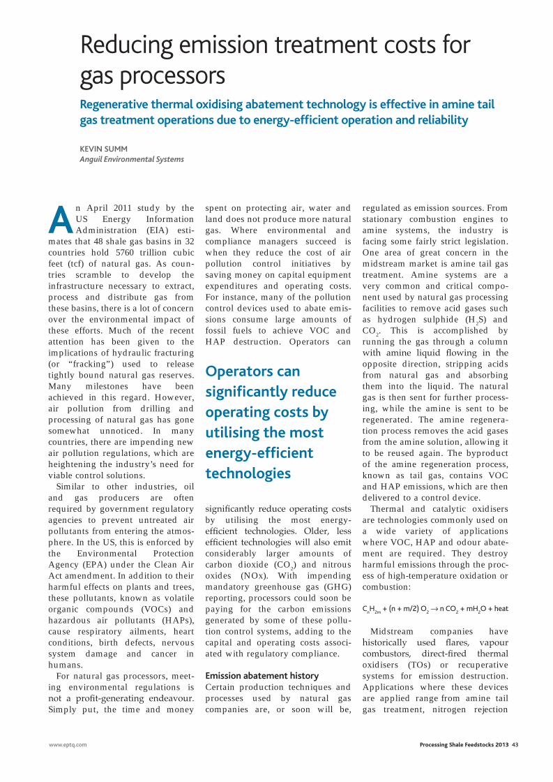
Reducing emission treatment costs for gas processors
An April 2011 study by the US Energy Information Administration (EIA) esti-
mates that 48 shale gas basins in 32 countries hold 5760 trillion cubic feet (tcf) of natural gas. As coun-tries scramble to develop the infrastructure necessary to extract, process and distribute gas from these basins, there is a lot of concern over the environmental impact of these efforts. Much of the recent attention has been given to the implications of hydraulic fracturing (or “fracking”) used to release tightly bound natural gas reserves. Many milestones have been achieved in this regard. However, air pollution from drilling and processing of natural gas has gone somewhat unnoticed. In many countries, there are impending new air pollution regulations, which are heightening the industry’s need for viable control solutions.
Similar to other industries, oil and gas producers are often required by government regulatory agencies to prevent untreated air pollutants from entering the atmos-phere. In the US, this is enforced by the Environmental Protection Agency (EPA) under the Clean Air Act amendment. In addition to their harmful effects on plants and trees, these pollutants, known as volatile organic compounds (VOCs) and hazardous air pollutants (HAPs), cause respiratory ailments, heart conditions, birth defects, nervous system damage and cancer in humans.
For natural gas processors, meet-ing environmental regulations is not a profit-generating endeavour. Simply put, the time and money
Regenerative thermal oxidising abatement technology is effective in amine tail gas treatment operations due to energy-efficient operation and reliability
Kevin SummAnguil Environmental Systems
spent on protecting air, water and land does not produce more natural gas. Where environmental and compliance managers succeed is when they reduce the cost of air pollution control initiatives by saving money on capital equipment expenditures and operating costs. For instance, many of the pollution control devices used to abate emis-sions consume large amounts of fossil fuels to achieve VOC and HAP destruction. Operators can
significantly reduce operating costs by utilising the most energy- efficient technologies. Older, less efficient technologies will also emit considerably larger amounts of carbon dioxide (CO2) and nitrous oxides (NOx). With impending mandatory greenhouse gas (GHG) reporting, processors could soon be paying for the carbon emissions generated by some of these pollu-tion control systems, adding to the capital and operating costs associ-ated with regulatory compliance.
emission abatement historyCertain production techniques and processes used by natural gas companies are, or soon will be,
regulated as emission sources. From stationary combustion engines to amine systems, the industry is facing some fairly strict legislation. One area of great concern in the midstream market is amine tail gas treatment. Amine systems are a very common and critical compo-nent used by natural gas processing facilities to remove acid gases such as hydrogen sulphide (H2S) and CO2. This is accomplished by running the gas through a column with amine liquid flowing in the opposite direction, stripping acids from natural gas and absorbing them into the liquid. The natural gas is then sent for further process-ing, while the amine is sent to be regenerated. The amine regenera-tion process removes the acid gases from the amine solution, allowing it to be reused again. The byproduct of the amine regeneration process, known as tail gas, contains VOC and HAP emissions, which are then delivered to a control device.
Thermal and catalytic oxidisers are technologies commonly used on a wide variety of applications where VOC, HAP and odour abate-ment are required. They destroy harmful emissions through the proc-ess of high-temperature oxidation or combustion:
CnH
2m + (n + m/2) O
2 → n CO
2 + mH
2O + heat
Midstream companies have historically used flares, vapour combustors, direct-fired thermal oxidisers (TOs) or recuperative systems for emission destruction. Applications where these devices are applied range from amine tail gas treatment, nitrogen rejection
www.eptq.com Processing Shale Feedstocks 2013 43
Operators can significantly reduce operating costs by utilising the most energy-efficient technologies
anguil.indd 1 26/02/2013 16:00
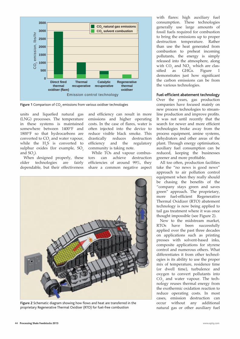
44 Processing Shale Feedstocks 2013 www.eptq.com
with flares: high auxiliary fuel consumption. These technologies generally use large amounts of fossil fuels required for combustion to bring the emissions up to proper destruction temperature. Rather than use the heat generated from combustion to preheat incoming pollutants, the energy is simply released into the atmosphere, along with CO2 and NOX, which are clas-sified as GHGs. Figure 1 demonstrates just how significant the carbon emissions can be from the various technologies.
Fuel-efficient abatement technologyOver the years, gas production companies have focused mainly on new process technologies to stream-line production and improve profits. It was not until recently that the search for newer and more efficient technologies broke away from the process equipment, amine systems, dehydrators and other areas of the plant. Through energy optimisation, auxiliary fuel consumption can be reduced, keeping the businesses greener and more profitable.
All too often, production facilities take the “no news is good news” approach to air pollution control equipment when they really should be chasing the benefits of the “company stays green and saves green” approach. The proprietary, more fuel-efficient Regenerative Thermal Oxidizer (RTO) abatement technology is now being applied to tail gas treatment where it was once thought impossible (see Figure 2).
New to the midstream market, RTOs have been successfully applied over the past three decades on applications such as printing presses with solvent-based inks, composite applications for styrene control and numerous others. What differentiates it from other technol-ogies is its ability to use the proper mix of temperature, residence time (or dwell time), turbulence and oxygen to convert pollutants into CO2 and water vapour. The tech-nology reuses thermal energy from the exothermic oxidation reaction to reduce operating costs. In most cases, emission destruction can occur without any additional natural gas or other auxiliary fuel
units and liquefied natural gas (LNG) processes. The temperature in these systems is maintained somewhere between 1400°F and 1800°F so that hydrocarbons are converted to CO2 and water vapour, while the H2S is converted to sulphur oxides (for example, SO2 and SO3).
When designed properly, these older technologies are fairly dependable, but their effectiveness
and efficiency can result in more emissions and higher operating costs. In the case of flares, water is often injected into the device to reduce visible black smoke. This drastically reduces destruction efficiency and the regulatory community is taking note.
While TOs and vapour combus-tors can achieve destruction efficiencies of around 99%, they share a common negative aspect
3000
3500
2500
2000
1500
1000
500
Direct fired thermal
oxidiser (flare)
Thermal recuperative
Catalytic recuperative
Regenerative thermal oxidiser
CO
2 e
mis
sion,
lbs/
hr
Emission control technology
0
CO2 natural gas emissionsCO2 solvent combustion
Figure 1 Comparison of CO2 emissions from various oxidiser technologies
Figure 2 Schematic diagram showing how flows and heat are transferred in the proprietary Regenerative Thermal Oxidiser (RTO) for fuel-free combustion
anguil.indd 2 26/02/2013 16:02

ABB Lifecycle Services. No one else knows yoursystems like we do.
With over 30 years of automation system heritage, no one else knows your ABBcontrol systems better than we do! And with our outstanding lifecycle policies andprograms, system expertise, evolution options, value added services and determinedcommitment to our customers, we can help you evolve to the latest in control systemtechnology with System 800xA. So, if you have an INFI90, MOD 300, Advant, DCI, orother control system, we are here to make sure your control system will continue tomeet your business needs now and in the future. For more information:www.abb.com/controlsystems
abb auto.indd 1 10/12/12 11:07:28
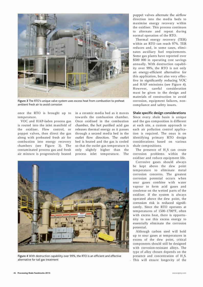
once the RTO is brought up to temperature.
VOC and HAP-laden process gas is routed into the inlet manifold of the oxidiser. Flow control, or poppet valves, then direct the gas along with preheated fresh air for combustion into energy recovery chambers (see Figure 3). The contaminated process gas and fresh air mixture is progressively heated
46 Processing Shale Feedstocks 2013 www.eptq.com
in a ceramic media bed as it moves towards the combustion chamber. Once oxidised in the combustion chamber, the hot purified acid gas releases thermal energy as it passes through a second media bed in the outlet flow direction. The outlet bed is heated and the gas is cooled so that the outlet gas temperature is only slightly higher than the process inlet temperature. The
poppet valves alternate the airflow direction into the media beds to maximise energy recovery within the oxidiser. This process continues to alternate and repeat during normal operation of the RTO.
Thermal energy recovery (TER) within an RTO can reach 97%. TER reduces and, in some cases, elimi-nates auxiliary fuel requirements. Some gas plants have reported over $500 000 in operating cost savings annually. With destruction capabil-ity over 99%, the RTO is not only an energy-efficient alternative for this application, but also very effec-tive in significantly reducing VOC and HAP emissions (see Figure 4). However, careful consideration must be given to the design and materials of construction to avoid corrosion, equipment failures, non-compliance and safety issues.
Shale specific design considerationsSince every shale basin is unique and the gas composition is different at each site, a custom approach to each air pollution control applica-tion is required. The onus is on identifying primary RTO design considerations based on various shale compositions.
The presence of H2S can create corrosion problems within the oxidiser and reduce equipment life.
Corrosive gases should always be kept above the dew point temperature to eliminate metal corrosion concerns. The greatest corrosion potential occurs when sour gases combine with water vapour to form acid gases and condense on the wetted parts of the oxidiser. If the system is always operated above the dew point, the corrosion risk is reduced signifi-cantly. Since the RTO operates at temperatures of 1500–1700°F, often with excess heat, there is opportu-nity to use this excess energy to essentially eliminate the corrosion potential.
Although carbon steel will hold up to sour gases at temperatures in excess of the dew point, critical components should still be designed with corrosion-resistant alloys. The type of alloy chosen depends on the presence and concentration of H2S. This will ensure longevity of the
Figure 3 The RTO’s unique valve system uses excess heat from combustion to preheat ambient fresh air to avoid corrosion
Figure 4 With destruction capability over 99%, the RTO is an efficient and effective alternative for tail gas treatment
anguil.indd 3 26/02/2013 14:56
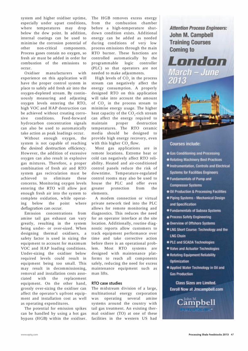
www.eptq.com Processing Shale Feedstocks 2013 47
system and higher oxidiser uptime, especially under upset conditions, where temperatures may drop below the dew point. In addition, internal coatings can be used to minimise the corrosion potential of other non-critical components. Process gases contain no oxygen, so fresh air must be added in order for combustion of the emissions to occur.
Oxidiser manufacturers with experience on this application will have the proper control system in place to safely add fresh air into the oxygen-depleted stream. By contin-uously measuring and adjusting oxygen levels entering the RTO, high VOC and HAP destruction can be achieved without creating corro-sive conditions. Feed-forward hydrocarbon concentration signals can also be used to automatically take action as peak loadings occur.
Without enough oxygen, the system is not capable of reaching the desired destruction efficiency. However, the addition of excessive oxygen can also result in explosive gas mixtures. Therefore, a proper combination of fresh air and RTO system gas recirculation must be achieved to eliminate these concerns. Monitoring oxygen levels entering the RTO will allow just enough fresh air into the system to complete oxidation, while operat-ing below the point where deflagration can occur.
Emission concentrations from amine tail gas exhaust can vary greatly, resulting in the system being under- or over-sized. When designing thermal oxidisers, a safety factor is used in sizing the equipment to account for maximum VOC and HAP loading conditions. Under-sizing the oxidiser below required levels could result in equipment being too small. This may result in decommissioning, removal and installation costs asso-ciated with the replacement equipment. On the other hand, grossly over-sizing the oxidiser can affect the operator’s upfront equip-ment and installation cost as well as operating expenditures.
The potential for emission spikes can be handled by using a hot gas bypass (HGB) within the oxidiser.
The HGB removes excess energy from the combustion chamber before a high-temperature shut-down condition exists. Additional energy can be added as needed during conditions of very low process emissions through the main RTO burner. These functions are controlled automatically by the programmable logic controller (PLC) so that operators are not needed to make adjustments.
High levels of CO2 in the process stream can negatively affect the energy consumption. A properly designed RTO on this application will take into account the amount of CO2 in the process stream to minimise energy usage. The higher heat capacity of the CO2-rich stream can affect the energy required to maintain proper destruction temperatures. The RTO ceramic media should be designed to provide high energy recovery, even with this higher CO2 flow.
Most gas applications are in remote locations. Extreme heat or cold can negatively affect RTO reli-ability. Heated and air-conditioned control panels reduce the risk of downtime. Temperature-regulated control rooms may also be used to house the PLC and offer even greater protection from the elements.
A modem connection or virtual private network tied into the PLC allows for remote monitoring and diagnostics. This reduces the need for an operator interface at the site location. Additionally, routine diag-nostic reports allow customers to track equipment performance over time and take corrective action before there is an operational prob-lem. Most RTO systems are designed with maintenance plat-forms to reach all components safely, reducing the need for excess maintenance equipment such as man lifts.
RTO case studiesThe midstream division of a large, multinational energy corporation was operating several amine systems around the country with tail gas treatment. An existing ther-mal oxidiser (TO) at one of these facilities in the western US had
anguil.indd 4 26/02/2013 14:56
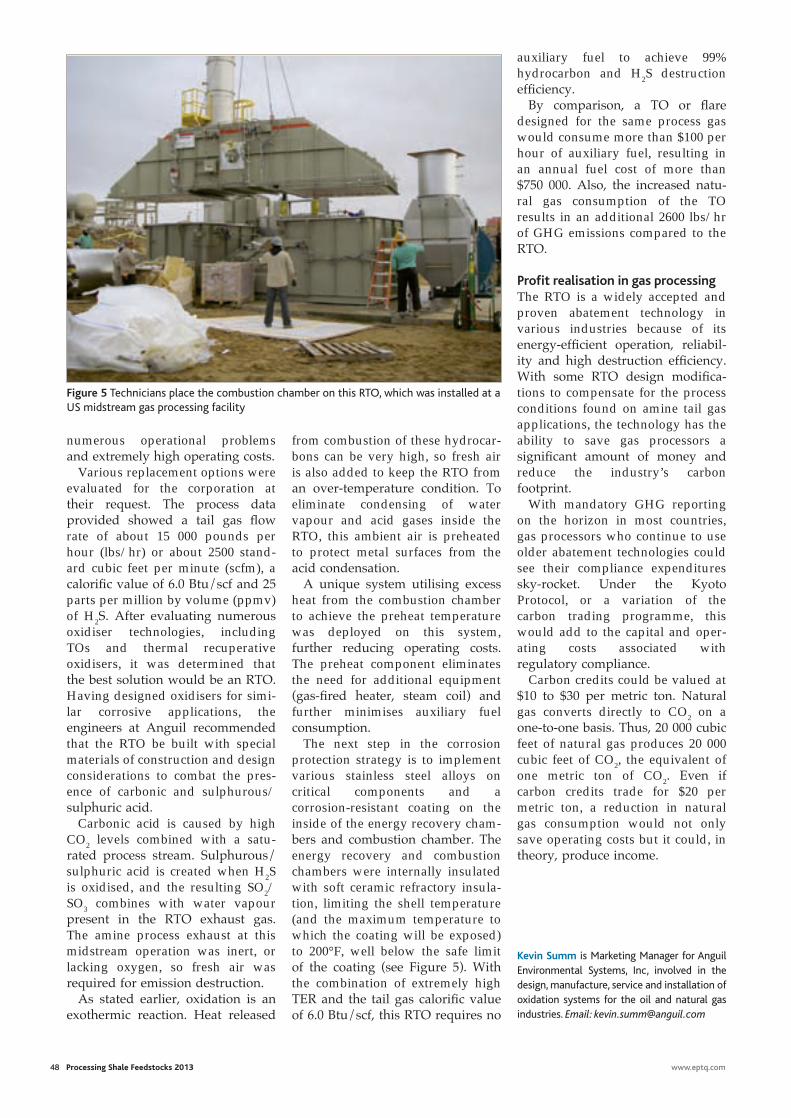
48 Processing Shale Feedstocks 2013 www.eptq.com
auxiliary fuel to achieve 99% hydrocarbon and H2S destruction efficiency.
By comparison, a TO or flare designed for the same process gas would consume more than $100 per hour of auxiliary fuel, resulting in an annual fuel cost of more than $750 000. Also, the increased natu-ral gas consumption of the TO results in an additional 2600 lbs/hr of GHG emissions compared to the RTO.
Profit realisation in gas processing The RTO is a widely accepted and proven abatement technology in various industries because of its energy-efficient operation, reliabil-ity and high destruction efficiency. With some RTO design modifica-tions to compensate for the process conditions found on amine tail gas applications, the technology has the ability to save gas processors a significant amount of money and reduce the industry’s carbon footprint.
With mandatory GHG reporting on the horizon in most countries, gas processors who continue to use older abatement technologies could see their compliance expenditures sky-rocket. Under the Kyoto Protocol, or a variation of the carbon trading programme, this would add to the capital and oper-ating costs associated with regulatory compliance.
Carbon credits could be valued at $10 to $30 per metric ton. Natural gas converts directly to CO2 on a one-to-one basis. Thus, 20 000 cubic feet of natural gas produces 20 000 cubic feet of CO2, the equivalent of one metric ton of CO2. Even if carbon credits trade for $20 per metric ton, a reduction in natural gas consumption would not only save operating costs but it could, in theory, produce income.
Kevin Summ is Marketing Manager for Anguil Environmental Systems, Inc, involved in the design, manufacture, service and installation of oxidation systems for the oil and natural gas industries. Email: [email protected]
numerous operational problems and extremely high operating costs.
Various replacement options were evaluated for the corporation at their request. The process data provided showed a tail gas flow rate of about 15 000 pounds per hour (lbs/hr) or about 2500 stand-ard cubic feet per minute (scfm), a calorific value of 6.0 Btu/scf and 25 parts per million by volume (ppmv) of H2S. After evaluating numerous oxidiser technologies, including TOs and thermal recuperative oxidisers, it was determined that the best solution would be an RTO. Having designed oxidisers for simi-lar corrosive applications, the engineers at Anguil recommended that the RTO be built with special materials of construction and design considerations to combat the pres-ence of carbonic and sulphurous/ sulphuric acid.
Carbonic acid is caused by high CO2 levels combined with a satu-rated process stream. Sulphurous/ sulphuric acid is created when H2S is oxidised, and the resulting SO2/SO3 combines with water vapour present in the RTO exhaust gas. The amine process exhaust at this midstream operation was inert, or lacking oxygen, so fresh air was required for emission destruction.
As stated earlier, oxidation is an exothermic reaction. Heat released
from combustion of these hydrocar-bons can be very high, so fresh air is also added to keep the RTO from an over-temperature condition. To eliminate condensing of water vapour and acid gases inside the RTO, this ambient air is preheated to protect metal surfaces from the acid condensation.
A unique system utilising excess heat from the combustion chamber to achieve the preheat temperature was deployed on this system, further reducing operating costs. The preheat component eliminates the need for additional equipment (gas-fired heater, steam coil) and further minimises auxiliary fuel consumption.
The next step in the corrosion protection strategy is to implement various stainless steel alloys on critical components and a corrosion-resistant coating on the inside of the energy recovery cham-bers and combustion chamber. The energy recovery and combustion chambers were internally insulated with soft ceramic refractory insula-tion, limiting the shell temperature (and the maximum temperature to which the coating will be exposed) to 200°F, well below the safe limit of the coating (see Figure 5). With the combination of extremely high TER and the tail gas calorific value of 6.0 Btu/scf, this RTO requires no
Figure 5 Technicians place the combustion chamber on this RTO, which was installed at a US midstream gas processing facility
anguil.indd 5 26/02/2013 14:56
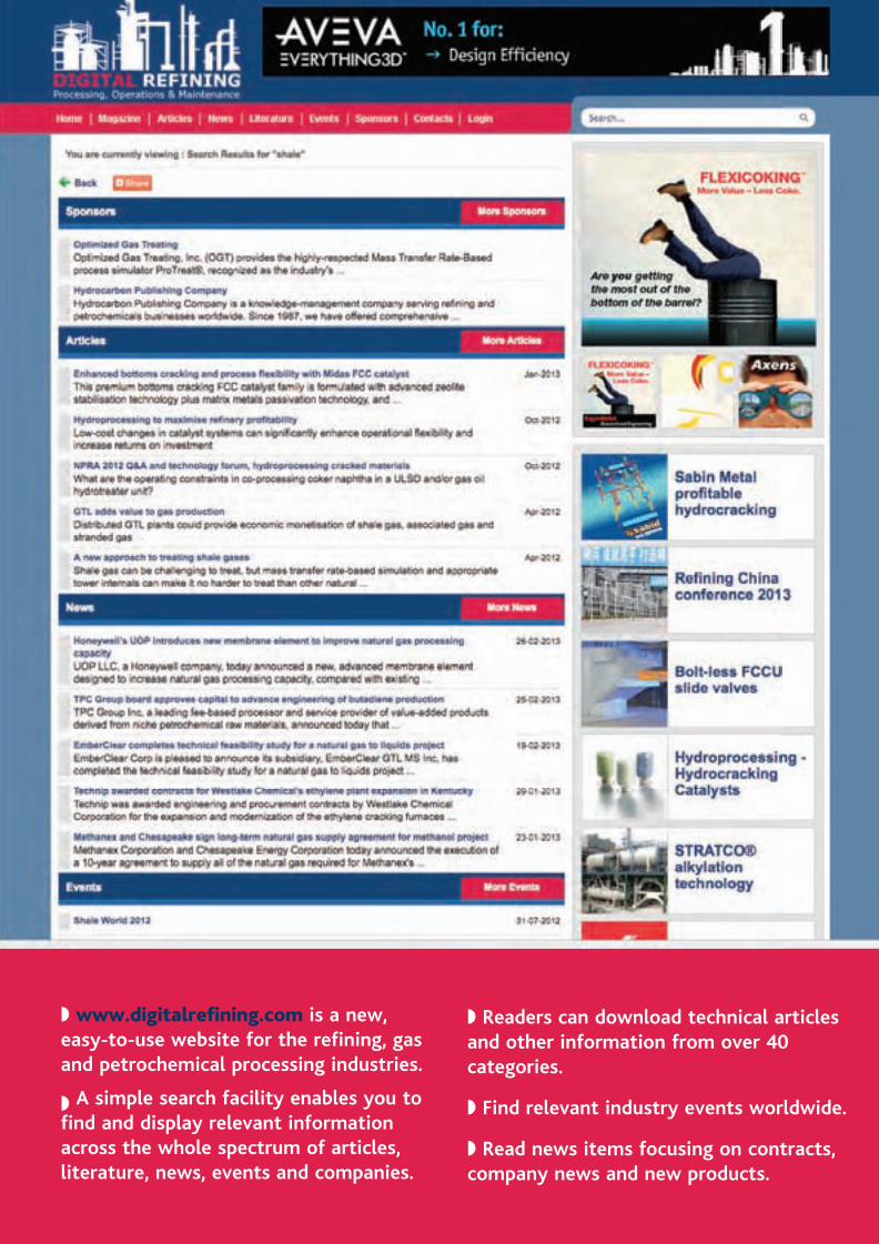
◗ www.digitalrefi ning.com is a new, easy-to-use website for the refi ning, gas and petrochemical processing industries.
◗ A simple search facility enables you to fi nd and display relevant information across the whole spectrum of articles, literature, news, events and companies.
◗ Readers can download technical articles and other information from over 40 categories.
◗ Find relevant industry events worldwide.
◗ Read news items focusing on contracts, company news and new products.
dig ref copy.indd 1 27/02/2013 10:44

Your objectivesin focus
Make the most of today’s and tomorrow’schallenges with leading-edge solutions from Axens
- Clean and alternative fuel technologies - Petrochemicals - Energy efficiency- High performance catalysts & adsorbents - Revamps
Single source technology and service providerISO 9001 – ISO 14001 – OHSAS 18001
www.axens.net
210/297.qxd:A4 13/08/10 12:12 Page 1
axens.indd 1 7/3/12 10:39:45