processing guidelines for the extrusion of thermoplastic …/media/chemicals/kl-media... ·...
TRANSCRIPT

Processing guidelines for the extrusion of thermoplastic vulcanizates
Santoprene™ TPVs
TABLE OF CONTENTS - 3
INTRODUCTION.................................................................................................................................................................................................. 5
EQUIPMENT.............................................................................................................................................................................................................. 6 Typical thermoplastic extruder ...................................................................................................................................................... 8Screw design....................................................................................................................................................................................................... 8 Extruder head..................................................................................................................................................................................................... 10Extrusion die ........................................................................................................................................................................................................ 11
GENERAL PROCESSING .......................................................................................................................................................................... 18Material drying .................................................................................................................................................................................................. 18Desiccant drying ............................................................................................................................................................................................. 18Colorability ............................................................................................................................................................................................................. 19
MATERIAL PROCESSING ........................................................................................................................................................................ 19Processing conditions .............................................................................................................................................................................. 19Start-up ..................................................................................................................................................................................................................... 20
DOWNSTREAM EQUIPMENT .......................................................................................................................................................... 21 Cooling ....................................................................................................................................................................................................................... 21Calibration and shaping ......................................................................................................................................................................... 22Haul-off systems ............................................................................................................................................................................................. 23Cutting systems ............................................................................................................................................................................................... 24Winding systems ...................................................................................................................... 24Regrinding.................................................................................................................................. 24Cleaning up ................................................................................................................................ 24Complex profile processes ..................................................................................................... 25Metal extrusion coating .......................................................................................................... 25Flocking ...................................................................................................................................... 25Slipcoating ................................................................................................................................. 25

INTRODUCTION - 5
INTRODUCTIONSantoprene™ thermoplastic vulcanizates (TPVs) are inherently easy materials to extrude into single and complex profiles.
Due to the nature of these materials (vulcanized rubber dispersed in a plastic matrix), they have excellent melt strength and exhibit low die swell. The extrusion of complex profiles can be achie ved, therefore, with minimal calibration of sizing equipment, while die design is straightforward.
This processing guide gives an extensive intro duc tion into many aspects of extrusion processing, including extruder selection, processing conditions for single extrusion and multiple extrusions, screw selection, die design, shaping and cooling, drying, use of regrind, and a wide range of in-line secondary processes and recommendations on the assembly of profiles.
The various TPVs referred to in this processing guide are similar in morphology and rheology. Their flow behavior is pseudo-plastic with melt viscosity, therefore, dependent on applied shear. This results in materials which are better controlled by the amount of shear applied by the screw speed, screw head and die design, and less controlled by conductive heat from the barrel.
Santoprene TPV grades can be co-extruded with each other and with polyolefinic (PO) materials. ExxonMobil Chemical also has bonding grades that can be co-extruded with a variety of non-PO substrates (PA, ABS, ASA, textile, metal and others).
The surface is smooth and consistent with a high coefficient of friction for soft grades. Soft gra des have a low-gloss, rubbery surface appearance. TPVs offer a relatively easy, economical way of producing rubbery extruded profiles for many markets and applications.
New technologies are available for physical foaming grades and chemical foaming grades, as well as surface modifications. For specialized applications, robotic extrusion grades have been developed.
These materials are briefly discussed in this document, but more information can be found in designated Technical Literature (TL), on the website (www.santoprene.com) or by contacting the AnswerPersonSM (see below). This information represents our observations and basic conditions for the extrusion of Santoprene TPVs from ExxonMobil Chemical based on our years of experience with processors. However, to provide as concise a guide as possible, and in view of the many potential variations depending on user preference, not all possible conditions are included.
For more information, contact the AnswerPersonSM at: [email protected] or visit us at www.santoprene.com

6 - EQUIPMENT
Figure 1 Exterior view of a typical single screw extruder
Figure 2Inside of a cross section of a typical single screw extruder
Cooling and haul-off
Gearbox
Hopper/drier
Feed throat
Feed throat (Cooled)
Barrel with separate heated and cooled sections
BarrelDie
Profile
Support for front end Base
Motor

EQUIPMENT - 7
Screw cooling
Figure 3 Cross section of a single screw extruder
Figure 4Different zones and functioning of an extruder
Screw and barrel
Control cabinet
Separate zones - typically heated or cooled by air or liquid
Feed zone - Zone 1 and 2
Melting zone - Zone 5Throat cooling
Transition zone - Zone 3 and 4

8 - EQUIPMENT
EQUIPMENT
Typical thermoplastic extruderThe selection of extruder size (barrel diameter) will depend on the size of the profile being produced at the production rate required. Small cross-sectional area profiles <10 cm2 (1.55 in2) are typically extruded on small diameter machines: 38 - 65 mm (1.5 - 2.5”).
Large cross-sections require larger diameter extruders 90 - 115 mm (3.5 - 4.5”). Throughput increases with the diameter of the machine, as shown in Table 1.
A length to diameter ratio (L/D) of 24:1 is typical. Longer L/D ratios of 30:1 or 32:1 are preferred as they deliver a higher output capability, a more uniform output rate and better melt homogeneity with the proper screw design (see Screw Design section).
The extruder should be equipped with a drive motor with sufficient horsepower to maintain a constant torque at various RPM and back pressure. Polymers like Santoprene TPVs have relatively high viscosity at the typical temperatures and shear rates developed during the extrusion process. Therefore, the extruder drive motor should deliver 0.25 KWH/kg (0.113 KWH/lb) to maintain constant output. The RPM should be controlled to at least 0.2% over the entire speed range from 0 to 100 RPM maximum. Since output increases linearly with RPM, a higher output rate will be achieved at a higher RPM.
Caution: Larger diameter extruders have a low surface area-to-volume ratio and could tend to overheat the melt, causing surging and reduced product quality at high RPM.
Screw designExtrusion of Santoprene TPV requires medium to high shear to properly plasticize and ensure ease of processing at recommended temperatures.
A general-purpose polyolefinic classical three-zone screw design (feed, transition/compression, metering/ pumping), having a compression ratio of 2.5 to 3.5 with an L/D of 24:1 to 30:1 is recommended (see Figure 6).
Other “special” type polyolefinic screws such as dual-flighted barrier screws, Maddock mixing screws and pin mixing screws also work very well when correctly designed. A decompression zone on the screw (i.e. between the transition section and the metering section) may cause a viscosity increase and irregular
output. A screw with a mixing head or with rows of mixing pins is recommended for incorporating color concen trates.
Barrier screws (see Figure 7), in combination with an axially grooved barrel section (see Figure 5) at the feed zone (maximum length of 4 L/D), have been used successfully and are recommended. Adequate cooling of the grooved feed section is vital to avoid bridging in the hopper.
*Assumes 24:1 L/D and ≤100 RPM; varies with screw design and grade (hardness) of Santoprene TPV. Specific gravity of all grades is ≤1.0.
European grooved feed section U.S. smooth bore feed section
Barrel diameter (mm) Output (kg/hr) Barrel diameter (inches) Output (lb/hr)
30 15 - 20 1.5 25 - 20
45 60 - 85 2.5 130 - 160
60 100 - 150 3.5 250 - 300
90 225 - 300 4.5 350 - 500
Table 1Typical output of Santoprene TPV*
Figure 5Grooved barrel
EQUIPMENT - 9
The barrier section should be positioned in the middle of the effective screw length with a gap between the barrier and the extruder barrel of 1.5 mm (0.060”) for all Santoprene TPV grades.
Advantages of the barrier screw/grooved barrel section system are increased output and a consistent homogeneous flow of the extrudate, especially for the softer Santoprene TPV grades (<75 Shore A hardness).
Grooved barrels do not produce as great an increase in output when used with a typical general-purpose p olyolefinic screw designs. Although not recommended, vented extruders, used with a two-stage screw, can be utilized for processing Santoprene TPV.
This system can eliminate the need for pre-drying of the material, but the output is lower and less stable due to the decompression at the vent section of the screw.
For certain applications, the use of a melt gear pump can increase the extrusion stability and profile quality. Vented twin screw extruders give a more consistent flow, but starve feeding is required which results in a reduced output.
Note: Non-vented single screw extruders are the preferred choice for processing Santoprene TPV into profiles with constant dimensions and at high extrusion speed. Screw cooling is NOT recommended.
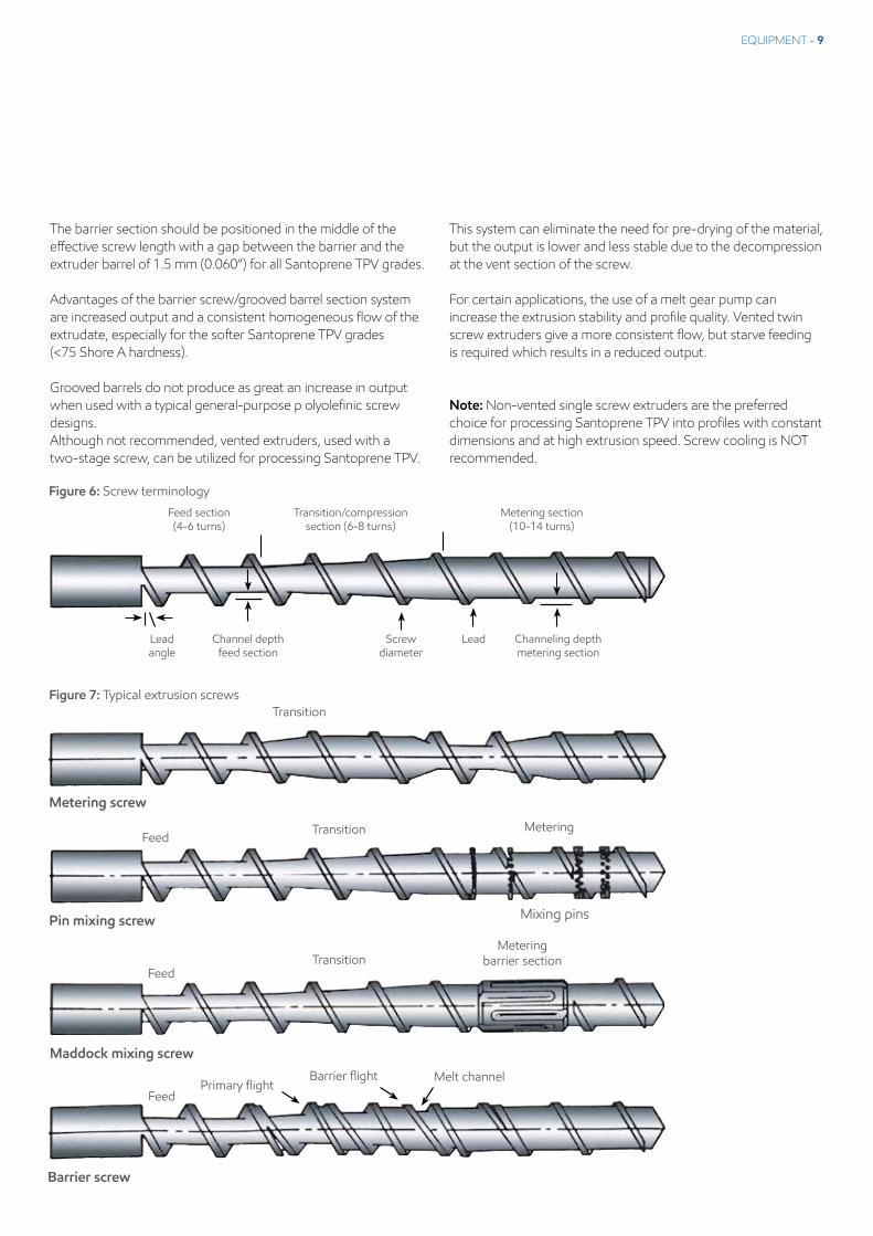
Figure 7: Typical extrusion screws
FeedTransition
Metering barrier section
Maddock mixing screw
FeedPrimary flight
Barrier flight Melt channel
Barrier screw
Transition
Metering screw
FeedTransition Metering
Pin mixing screw Mixing pins
Figure 6: Screw terminology
Feed section(4-6 turns)
Transition/compressionsection (6-8 turns)
Metering section(10-14 turns)
Lead angle
Channel depthfeed section
Screwdiameter
Lead Channeling depth metering section

10 - EQUIPMENT
Extruder headExtruder heads usually contain a relaxation /decompression zone (see Figure 8), after the polymer melt has been compressed coming from the extruder barrel. The purpose of such a relaxation zone, together with a mixing head on the screw and a breaker plate in the extruder head, is to change the rotational flow into uniform laminar flow. After this relaxation zone and until the extrusion die exit, no further decompression should occur, as it will lead to irregular output of a Santoprene TPV extrudate. Breaker plates with holes of 2.0 - 4.0 mm (0.080 - 0.160”) diameter, depending on the extruder size, are recommended in combination with a screen pack. An example
of a typical screen combination is a 20, 40 and 60 mesh screen, whereby the 20 mesh screen is in contact with the breaker plate and supports the finer screens.
The purpose of a screen pack (see Figure 9) is to protect the extrusion die, homogenize the melt, increase screw back pressure, increase shear, and generally improve surface quality. In general, screen packs are not considered as a filter for impurities in the polymer melt, such as gel particles. However, the use of fine screen packs will increase the work on the material and increase back pressure.
Figure 8Extrusion head design
Figure 9Typical screen pack
Air inlet
Die plate
Compression zone
Relaxation zone
Land
Breaker plate holes(diameter 2 to 4 mm)
- - - - - - - - - -
Die
Extruder
60 - 40 - 20Mesh

EQUIPMENT - 11
Extruder dieThe main purpose of an extrusion die is to produce a profile with tight dimensional tolerances from the polymer melt delivered by the extruder. When the melt enters the extrusion die section from the screen pack/breaker plate, it should be further streamlined to the die exit. Converging flow paths are preferred. Decompression in the tooling head and die will lead to very irregular flow.
The die plate needs to be balanced so that the extrudate leaves the extrusion die straight and not curved: exiting the die at the same velocity in every section of the profile (for further information, re fer to the Extrusion Die Design section).
Back pressureRecommended back pressure measured in the extruder head should be a minimum of 50 bar (725 psi) to guarantee a constant melt flow.
Pressure over 200 bar (2900 psi) is not recom men ded, as it may lead to increased melt temperature at the extruder head and possible polymer degradation.
Should such high pressure occur, then a smaller size extruder is recommended, or the extruder head should be modified.
Temperature control extruder headIt is important to divide the extruder head into several different heating zones, with good tempe rature control.
One zone should be the mounting part of the head to the barrel; the second zone will be the adapter plate comprising the relaxation zone plus screen pack/breaker plate; the third zone is the complete extrusion die.
For optimal extrusion of Santoprene TPV, it is recommended that the melt temperature is measured at (or close to) the land of the final die plate. Avoid interruption of the flow by having the tempe rature sensor flush with the die wall.
General extrusion die design In general, Santoprene TPV will swell more in thickness than in
width and length, requiring different sizing of the opening to obtain the correct profile thickness.
Harder grades of Santoprene TPV will swell more than softer grades. At normal extrusion melt temperatures (195 - 215°C / 383 - 419°F), swell differs slightly and primarily for hard grades.
The key variable affecting swell is the shear rate; a function of the die opening/gap and the material velocity. The higher the extrusion speed or the smaller the die gap, the greater the shear rate and, therefore, the greater the die swell.
A small profile die extruded at a high line speed will, therefore, exhibit much greater swell than a profile with thicker walls running on the same extruder. Thus, the choice of extruder and profile will greatly influence the design of the die gap.
Oversize of extrusion diesThe die swell of a Santoprene TPV extrudate is determined by its hardness, melt temperature, melt viscosity, flow rate and land length of the die. In fact, it is reasonable to assume that a properly designed die can be used to produce parts from a range of Santoprene TPV grades, either harder or softer than the specific hardness it was designed for. However, some re-balancing of the flow pattern may be required.
Harder grades can withstand higher drawdown rates than softer grades to obtain their final dimen sions. Also, shaping or calibration techniques can be more easily applied.
In general, Santoprene TPV grades swell differently in wall thickness than in the overall profile width. This effect is more pronounced for harder grades, as they swell more than softer grades. Therefore, the die orifice requires different over-/undersizing to obtain the correct profile dimensions (see Table 2).
Consequently, very thick profiles may need to be oversized by 15% for ease of balancing. Higher die swell may be seen on thin-walled small profiles run at high line speeds. In this case, major dimensions could be held on size to reduce orientation and shrinkage caused by too much drawdown.

12 - EQUIPMENT
Balancing the flow through the die As with most materials, Santoprene TPV will tend to “center flow.” The center of any orifice is the point of least back pressure and hence the path of least resistance to flow. This effect causes a difficulty in filling out corners of dies and thinner sections. To compensate for this tendency, it is necessary to “balance the die” by adjusting the land lengths behind the die face (see Figure 11). In general, the land length to thickness ratio should be uniform. Thus, a thin section of the die which has a 5:1 land length ratio will have a much shorter actual land length than a thick section of the die. While this general rule is sufficient to build a die that is close enough to produce good parts, it is usually necessary to make adjustments after the die has been built.
Ideally, when fully balanced, the flow through the die should exit at the same velocity across the entire die face in a free extrusion condition. This is similar to centering a tubing die. The basic idea is to achieve equal pressure drop across the land plate for the entire cross-section of the profile by selectively machining the flow entrance channel on the back of the die. Different methods could be used to accomplish this, depending on die complexity and size (see Figure 10).
On a flat plate die, provide a tapered section, which would give the effect of increasing flow compression and shortening the land length. A shorter land length produces a lower pressure drop across that section, which in turn allows more material to flow through the die (see Table 3).
Land length ratio (thick) should equal land length ratio (thin). If not equal, downsize land length ratio of thinner section to equal that of thicker section.
For profiles with more than two thicknesses, use this formula to determine land length ratio for all dimensions and downsize all to equal the shortest land length.
Figure 10Single extrusion die - rear view
Table 2Die dimensions
Wall thickness Oversize soft grades by (≤80A durometer) Oversize hard grades by (≤87A durometer)
< 3 mm or 0.120” 0 - 7% 5 - 10%
3 - 6 mm or 0.120 - 0.240” 5 - 10% 10 - 20%
> 6 mm or 0.240” 10 - 15% 10 - 20%

EQUIPMENT - 13
Plate 1Front view
Plate 2Rear view
Figure 11Die design - Multiple plate concept - Balancing of the melt flow by carefully positioned separators
Material flow direction
Plate 1
Plate 2
Plate 3
Table 3Land length ratio formula
Overall thickness of the die = Land length ratio (thick)
Thickest dimension of the part
Overall thickness of the die = Land length ratio (thin)
Thinnest dimension of the part
For most extrusion dies for Santoprene TPV, the above equations will provide land length ratios for a profile with multiple wall thicknesses.

14 - EQUIPMENT
Hollow cross-section There are several methods to produce hollow cross-sections. When using a wire EDM (Electro Discharge Machining) to cut a die, leave support webs between outer and inner sections. The webs (spider legs) must be streamlined to allow for good knit of the melt. Reduce the number of webs to minimize the number of knit lines.
A pin can be cut and attached to a bridge on the rear of the die. The bridge must be streamlined to achieve good knit line strength (see Figure 12).
Land length ratio The desired ratio (nominally 5:1) of the land length of the die to the die gap thickness (the land length ratio) varies between 1:1 and 10:1, depending on the profile design. The ratio affects the thickness of the die land plate.
Complex dies for single extrusionComplex dies are those extrusion dies where the thickness of the profile varies between 0.5 - 3.0 mm (0.019 - 0.120”) and where hollow section(s) are present. For these situations, a die plate of 20 - 30 mm thick (0.787 - 1.18”) is typical. In general, the hollow sections are made by small pins at the rear of the die plate fixed to a bridge or support rib. A connection through the front of the die plate allows air to be supplied through the small pins to prevent the hollow section(s) collapsing (see Figure 13).
Care must be taken that the presence of a bridge does not cause any decompression between the breaker plate and the die plate. Effective stream lining of the cone, which moves the polymer melt from the breaker plate to the die plate, should avoid decompression. Also, the bridge must be streamlined to avoid dead/stagnant corners where polymer degradation may occur.
Figure 12Single extrusion die - rear view
Figure 13Single extrusion die - rear view
EQUIPMENT - 15
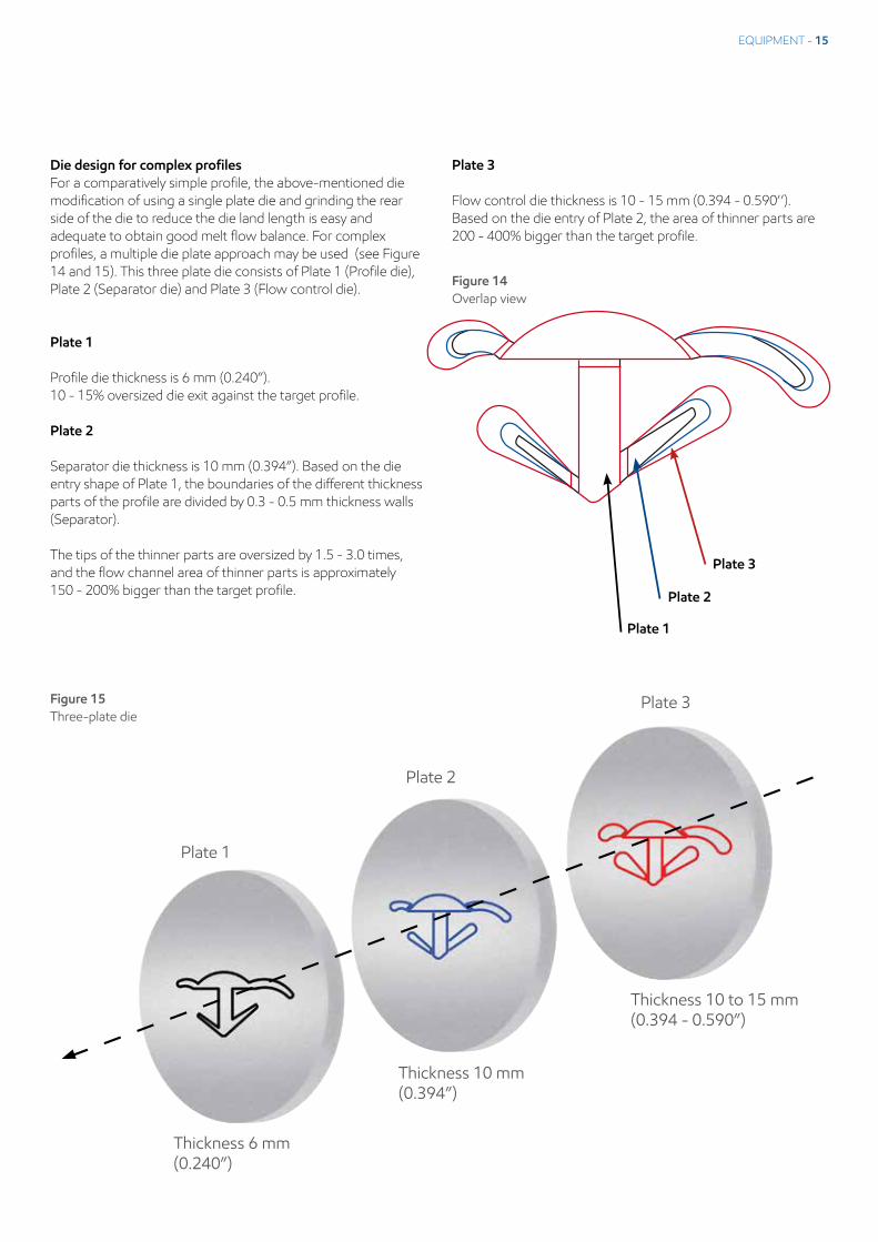
Die design for complex profilesFor a comparatively simple profile, the above-mentioned die modification of using a single plate die and grinding the rear side of the die to reduce the die land length is easy and adequate to obtain good melt flow balance. For complex profiles, a multiple die plate approach may be used (see Figure 14 and 15). This three plate die consists of Plate 1 (Profile die), Plate 2 (Separator die) and Plate 3 (Flow control die).
Plate 1
Profile die thickness is 6 mm (0.240”). 10 - 15% oversized die exit against the target profile.
Plate 2
Separator die thickness is 10 mm (0.394”). Based on the die entry shape of Plate 1, the boun daries of the different thickness parts of the profile are divided by 0.3 - 0.5 mm thickness walls (Separator).
The tips of the thinner parts are oversized by 1.5 - 3.0 times, and the flow channel area of thinner parts is approximately 150 - 200% bigger than the target profile.
Plate 3
Flow control die thickness is 10 - 15 mm (0.394 - 0.590’’). Based on the die entry of Plate 2, the area of thinner parts are 200 - 400% bigger than the target profile.
Plate 1
Plate 2
Plate 3
Figure 14Overlap view
Plate 2
Plate 3
Thickness 6 mm(0.240”)
Thickness 10 mm(0.394”)
Thickness 10 to 15 mm(0.394 - 0.590”)
Plate 1
Figure 15Three-plate die

16 - EQUIPMENT
Die design for complex profiles (continued)
Procedure of 3-plate die modification
Step 1Set Plate 2 (Separator die) and Plate 3 (Flow control die) to the head and conduct an extrusion trial. The extruded profile is divided by each separator.
Step 2Check the difference in velocities between each extrudate. If the velocities are different, grind the back plate of Plate 3 where the slower velocity is observed, creating an increased flow channel, in order to achieve equivalent velocities.
Step 3Having obtained equivalent melt flow velocities of each divided extrudate, grind the wall of the separator from the front side (around 3 - 4 mm, 0.118 - 0.157”) of the Plate 2 to get smooth confluence of the divided melt flows (similar to a torpedo).
Step 4Conduct an extrusion trial adding Plate 1 (profile die) to the modified Plate 2 and Plate 3. Check the whole profile shape of the extrudate. If unaccep table thickness and edge tear are observed, modify the melt flow channels of Plate 3 and Plate 2 where the thinness/edge tear occurred. Also, chamfer the edge of the melt channels behind Plate 1 to get smooth melt flow from the die exit of Plate 2.
Note: When using recycled material, the die modification should be made beforehand with the same mixing rate of recycled material. The melt viscosity between original and recycled material is slightly different which usually causes different melt flow.
Extrusion dies for tubingDepending on wall thickness, extruded tubes should not be larger in diameter than 70% of the extruder barrel diameter so that sufficient pressure can be generated in the extrusion die. Usually the air flow inside the tube is obtained via an air inlet through the spider (see Figure 16) or the breaker plate to which the internal pin is fixed.
Tube dies of polyolefinic design with parallel land length between 25 - 50 mm (0.98 - 1.967”) are recom mended. Spiders can have up to four webs, and breaker plates can be holed with 1 - 2 mm (0.039 - 0.078”) diameter air inlet. Distance between a spider and the die exit should be a minimum of 125 mm (4.92”) so that the turbulent flows caused by the spider will be eliminated.
Co-extrusion diesIn general, the principals for single extrusion can be applied to co-extrusion of various Santoprene TPV grades. Typically use a die plate of 50 mm (1.96”) thickness for the first material entry, and streamline to the center. For the second material entry, use another die plate of 50 mm (1.96”) thickness, and channel the polymer flow around the center of the first polymer.
A third die plate of 25 - 50 mm (0.98 - 1.96”) thickness may be necessary to channel the two polymer flows together.
Figure 16Complex die for tubing

EQUIPMENT - 17
The necessity of a third plate depends on the complexity of the profile. The last die plate should have a minimum thickness of 10 mm (0.394”) so that the two polymer melts flow overlay completely creating a strong weld/bond.
In the last die plate, the profile gets its final confi guration (see Figures 17 and 18). Accurate tempe rature control on all die plates is critical. Tempe ra tures should be set to achieve optimal flow but not exceeding 215°C (420°F).
Should adhesion be an issue, increase the tempe rature of the softer material bringing it closer to the melt temperature of the harder material.
Tri-extrusion diesAs with co-extrusion die design, the principles can be applied to tri-extrusion die design. An additional extrusion die plate of 50 mm (1.96”) thickness for the third polymer entry may be used.
It is highly recommended that extra care and attention be given to the off-set (angled to profile flow) extruders which feed the multiple extrusion with respect to screen packs, decom pression zones, connection to the extrusion die, and flow paths. Melt stagnation of polymer melts may occur from these secondary extruders and may completely unbalance the flow of all polymers in the multiple-extrusion die.
It is highly recommended when extruding multiple component profiles using Santoprene TPV that all extruders are optimally laid out.
Metal type, surface and surface treatment for extrusion dies and headsIt is recommended to use steel which is easy to machine but fairly hard. The steel used should have a low carbon content and a minimum of 13.6% chrome (Cr). Typical steel would be 0.38 C, 0.50 Si, 0.50 Mn, 13.6% Cr. The die wall should not be polished. The surface roughness of the extrusion die face should be <3 micron surface roughness (Ra).
It is good practice to dismantle the extrusion die after extrusion and to clean mechanically with brass tools. After cleaning, the application of a metal anti-corrosion, spray to preserve the dies is highly recommended.
Typical surface treatments are nitration, which improves wear resistance, and nickel plating which improves corrosion and wear resistance. Chrome plating is the preferred treatment for corrosion, but it tends to have a shorter life due to its porous structure.
Figure 17Co-extrusion die - exit view
Figure 18Co-extrusion die - entry view

18 - GENERAL PROCESSING
GENERAL PROCESSING
Material dryingTo produce profiles of optimal quality, it is essential to use consistently dry material. Excessive moisture levels (eg. >0.045% for 121-73W175, see Figure 19) have been found to cause surface finish defects in the form of porosity, void formation, surging, low melt strength and irregular profile (feathered) edges. Using an effective drying system will result in good quality profiles.
Desiccant dryingA desiccant drying system is best suited for opti mum drying of Santoprene TPV (see Figure 20). This can be a floor- or hopper- mounted system which should deliver low dew point air (below -21°C, -5°F) at the appropriate temperature of about 65 - 85°C (150 - 185°F) with a continuous flow rate (>1.5 m3/min/kg, >25 ft3/min./lb).
This provides a uniform drying environment irrespec tive of ambient conditions. Pre-drying for three hours is recommended before start-up. For continuous operation, the hopper dryer should be capable of holding enough resin for at least two hours of throughput.
Material discharge valve
Granules of Santoprene TPV
Hopper
Valve
Humid air
Dried air Dew point meter
Typical -10 to -21OC (14 to -5OF)
Valve
2 to 3 hrs. at 80OC (180OF)
Heater
Desiccantcompound
Heater
Desiccantcompound
0 1 2 3 4 5
0.14
0.12
0.10
0.08
0.06
0.04
0.02
0.00
Moi
stur
e (%
)
Hours dried at 82°C (180°F)
121-73W175 Max. moisture level for processing 121-73W175 123-50W175 Max. moisture level for processing 123-50W175 Max. moisture level at packing
Figure 19Moisture levels (typical values) of Santoprene W175 TPVs
Figure 20Typical desiccant circulating air drying equipment

MATERIAL PROCESSING - 19
ColorabilityNatural grades of Santoprene TPV are easy to color. It is best to use masterbatches to color natural Santoprene TPV grades. Color concen trates of pure dry color or in liquid form are not recommended since they are more difficult to disperse. It is important to remember that the addition of a color concentrate may affect the processability and/or the material properties. It is best to use either a poly ethy lene- or a poly propylene-based carrier, prefe rably with the same viscosity as Santoprene TPV for
better dispersion. For specialty bonding grades, please check with your local repre sentative for the optimal carrier material. It is good practice to use pre-dried color concentrates prior to adding Santoprene TPV, or to dry Santoprene TPV pre-blended with the concen trate at recommended conditions. It should be noted, however, that when adding color, material weatherability, physical pro perties and surface appearance can be affected.
MATERIAL PROCESSING
Processing conditionsThe various grades of Santoprene TPV all have similar processing conditions. It is strongly advised that all grades be dried before extruding. See Material Drying section for complete details.
Feed throat cooling is necessary to prevent bridging in the hopper and air entrapment in the melt.
The actual extruder barrel temperature setting will vary depending on the extruder L/D, screw design, and grade of Santoprene TPV. It is best to operate at the lowest possible melt
tempe rature that will produce a good quality extrudate. This is achieved by using a low feed zone tempe rature and by gradually increasing the temperature along the barrel zones ending at the die.
Lower temperature settings generally provide slightly higher output rates. Recommended starting temperature profiles are shown in Tables 3 and 4. The most important temperature is the melt temperature. Adjust the barrel tempe ratures to achieve the recommended melt temperature.
Figure 19Temperature profiles for various hardnesses of Santoprene TPV
35A 45A 55A 64A 73A 80A 87A 40D 50D
Zone 1 (Feed) °C°F
165 329
170 338
175 347
175 347
180 356
180 356
190 374
195 383
195 383
Zone 2 °C°F
170 338
175 347
180 356
180 356
180 356
180 356
190 374
195 383
195 383
Zone 3 °C°F
175347
180 356
180 356
180 356
190 374
190 374
195 383
200 392
200 392
Zone 4 °C°F
180 356
190 374
190 374
190 374
195 383
195 383
200 392
205 401
205 401
Head °C°F
190 374
195 383
195 383
195 383
200 392
200 392
205 401
210 410
210 410
Die °C°F
195 383
200 392
200 392
200 392
205 401
205 401
201 410
215 419
215 419
Melt °C°F
190-195 374-383
190-195 374-383
190-200 374-392
190-200 374-392
195-205 383-401
195-205 383-401
200-210 392-410
210-215 410-419
210-215 410-419

20 - MATERIAL PROCESSING
8201-60 8271-55 8271-65
8201-70 8271-75
8201-80
Zone 1 °C°F
165-195329-383
175-200 347-392
180-205 356-401
185-210 365-410
Zone 2 °C°F
170-200 338-392
180-205 356-401
185-210 365-410
190-215 374-419
Zone 3 °C°F
175-205 347-401
185-210 365-410
190-215 374-419
195-220 383-428
Zone 4 °C°F
175-205 347-401
185-210 365-410
190-215 374-419
195-220 383-428
Head °C°F
180-210 356-410
185-215 365-419
190-220 374-428
195-220 383-428
Die °C°F
180-215 356-419
185-220 365-428
190-225 374-437
195-225 383-437
Melt °C°F
180-215 356-419
185-220 365-428
190-225 374-437
195-225 383-437
Table 4 : Temperature profiles for Santoprene 8000 TPV grades
Start-upTo prevent surface spots caused by material remaining in the die/head/screw, it is better to clean the extruder before starting extrusion.
Set the barrel and die temperatures as per Tables 3 and 4, when starting to clean the machine. Before starting extrusion, allow a minimum of one-half hour of “heat-soak” after all temperature controllers have reached their set point. This will allow the feedscrew to reach operating temperature.
When reheating an extruder which has been shut down with resin in the barrel, care must be taken. Therefore, the barrel should be evenly heated to its processing temperature. A minimum of one hour of heat soak is recommended once operating temperatures have been reached. Then processing/
extrusion can be started. The extruder should be started at a very low rate. Once material is exiting the die and the head pressure is not excessive (<200 Bar, <2900 psi), RPM can be increased to the normal operating running speed.
Be warned that an extruder previously used to process other thermoplastics must be thoroughly purged prior to running Santo prene TPVs. Acetal and PVC combined with Santoprene TPVs in the melt can decompose and release toxic gases, such as formal de hyde or hydrochloric acid. Therefore, thorough cleaning of machine and equipment is manda tory.
If not feasible, a low melt index polypropylene or polyethylene should be used for thorough purging. Follow the same purge procedure after extru ding TPVs.

DOWNSTREAM EQUIPMENT - 21
Figure 21Cooling line with roller support
DOWNSTREAM EQUIPMENT
CoolingSoft grades of Santoprene TPV have good melt strength plus excellent shape retention, and exhibit very low die swell. Therefore, most extrusion profiles are cooled by water spray and/or water immersion, without the need for calibrators or vacuum-sizing systems. Even complex shapes of single-material extru sions can be “free-formed” to produce extru dates of uniform shape and good dimensional tolerance.
For co- or tri-extrusion using different polymers (e.g. polypropylene) in combination with Santo prene TPV, it may be necessary to use shaping or calibration fixtures to prevent warping caused by differential cooling rates. Harder grades of Santoprene TPV (87 Shore A and harder) will normally require a shaping fixture to hold the desired geometry until cooled sufficiently to main tain profile integrity (see Calibration/Shaping section).
Most grades of Santoprene TPV have a specific gravity below that of water. Thus, extrudate will float. This gives a differential cooling efficiency and can change the shape of the profile. Attempts to hold the profile underwater using overhead rollers may only cause additional distortion. The total effect is much more pronounced in harder grades, starting from > 87 Shore A.
The preferred method for cooling profiles is a closed-loop water spray system (see Figures 21 and 22). Water spray is actually a more effective cooling method than water immersion, at least initially. When the extrudate surface temperature is
above the boiling point of water, the water spray is converted to steam. Thus, the heat energy to vaporize water is removed from the profile surface. In addition, spraying assures turbulent flow. This effectively doubles the cooling efficiency compared to immersion. When the surface temperature is reduced to 100°C (212°F), water immersion can be used for final cooling.
The length of the cooling bath will depend on two main factors – profile maximum thickness and line speed. Thicker parts or higher line speeds will need longer cooling baths to achieve sufficient coolant residence time to prevent profile distortion by haul-off, cutting or winding equipment.
Common cooling bath lengths vary between two meters and twenty meters (seven and sixty-six feet). Typically, the cooling/support system is about 2.5 - 4.0 cm (1 - 1.5”) from the die exit. In order to reduce cooling bath length, a multi pass (loop-back) system or a multi profile die can be used (at same output with lower speed).
The best-quality extrudates for winding, coiling or cutting are obtained when cooling is sufficient to reduce the profile temperature to <37.8°C (100°F). The thermal conductivity for Santoprene TPV is approximately 0.145 W/m sec °K (0.084BTU/ hr x ft x °F). All these factors can be combined to determine the required cooling bath length.
Figure 22Cooling line with water spray and roller support

22 - DOWNSTREAM EQUIPMENT
Calibration and shapingFor some shapes, it is sufficient to orient the die so that the heavy section is on the bottom. This heavy (thick) section can act as a support for traveling over rollers and/or conveyor belts and can also serve as a support for guillotine or in-line cutting to length. When this step is not sufficient to maintain required geometry, additional shaping must be applied.
The simplest shaping device is a metal rod or a flat bar. These are mounted at the beginning of the cooling system. Many times, these metal “fingers” are coated with a low-friction, silver-flake-filled PTFE to compensate for the relatively high coefficient of friction of softer grades of Santoprene TPV (<87 Shore A). In addition, a water spray may be directed at the polymer/shaping device interface to begin cooling and to provide a water lubricant film. When these steps are not sufficient to produce the desired geometry, a full sizing fixture must be used. With some profiles, it may be possible to maintain shape with a single flat metal plate, approximately 6 mm (0.23”) thick, which has been cut to the desired profile shape, but is about 5% oversize (see Figures 23 and 24). The plate is usually split horizontally to allow easy “string-up or start-up”, after which the top half is installed.
Calibration/shaping fixtures are recommended for single durometer extrusions >87 Shore A and multi-durometer profiles. For complex profiles with metal inserts having a limited amount of polymer (whether a hard or a soft grade of Santoprene TPV), no or limited calibration is required as the metal insert acts as a support during the cooling process.
Sometimes, in order to achieve desired geometry and surface quality, it may be necessary to prepare a full calibration unit, including vacuum. Generally, these systems work best with sections made of harder grades (>87 shore A) of Santoprene TPV or polypropylene. The higher coefficient of friction of soft grades restricts the use of calibration techniques to simple shapes with small surface area.
Calibrator systems are usually a series of thin 2 - 3 mm (0.078 - 0.118”) flat plates, cut very close to the final desired size of the profile. The distance between plates may be constant or variable. The plate thickness also may be variable.The dimensions of the orifice/shape in the fixture(s) are usually very close to the desired profile dimensions, but they are 2 - 3% oversize to allow for shrinkage upon cooling (see Figures 25 and 26).
Figure 23Shape retention fixture
Figure 24With incorporated water cooling
Figure 25Block calibrator (open)
Figure 26Block calibrator (closed)

MOLD DESIGN - 23
Calibration and shaping (continued)For tubing, the ultimate calibration device is a vacuum box. This system provides a long >250 mm (>10”) continuous contact surface, broken intermittently by shallow grooves perpendicular to the flow. These channels allow a vacuum to be established in the box. This system is best for polishing hard grades and maintaining straightness. The polished metal surface is cooled and may be coated with a low friction material, and draw polished (see Figures 27 and 28).
Haul-off systemsTable 5 shows typical line speeds for Santoprene TPV products for haul-off factor comparisons.
The haul-off system is the key to dimensional control and to stability of the profile geometry, once constant output from the extruder has been attained, and cooling and calibration has been established. Usually, this is a pair of variable speed continuous belts whose gap or separation distance can be adjusted. Pressure on the profile should be just sufficient to assure positive contact and, hence, no slippage. Excess pressure may deform the profile.
Haul-off systems must be capable of maintaining a reasonably constant speed (± 0.5%). The haul-off system for an un-reinforced profile is typically run at a linear speed that is 2 - 10% higher than that of the extrudate. This ensures that tension is maintained on the profile, which promotes straightness (no curling, warping or distortion). The extra speed of the haul-off system, normally called drawdown, should be kept as low as possible. High drawdown ratios can lead to too much residual stress in the polymer and can cause high shrinkage or warpage of the finished profile.
Care must be taken when working with metal inserts which are pulled (or pushed) through the die during the extrusion process. Consistent extrusion profiles can only be obtained when a sufficiently stable and powerful haul-off system is used.
Figure 27 Block calibrator (open)
Table 5Typical line speed
Figure 28Hose calibrator
Extrusion product Extruder diameter Typical line speed
Centimeters Inches Feet per minute Meters per minute
Hose Cover 6.35 2.5 9.1 - 30.5 30 - 100
Profile 6.35 2.5 15.2 - 61.0 50 - 200
Sheet 11.43 4.5 0.3 - 0.46 1 - 1.5
Tubing 6.35 2.5 9.1 - 30.5 30 - 100
Wire Insulation 6.35 - 8.89 2.5 - 3.5 305 - 3050 1000 - 10000
Wire Jacketing 6.35 - 8.89 2.5 - 3.5 30.5 - 91.4 100 - 300

24 - DOWNSTREAM EQUIPMENT
Cutting systemsWith many profiles, in-line cutting or punching is required. In-line cutting to size is especially recom mended when the profile hardness is 87 Shore A or greater. When cutting to length, allowance must be made for a post-cut shrinkage. The expected shrinkage will vary, depending on drawdown, thickness and the grade of Santoprene TPV. Generally, the expected linear shrinkage will be 0.5 - 0.7% for an extruded profile, produced with minimal drawdown and cooled sufficiently to at least 35°C (95°F) or below before cutting.
Cutting can be done by a guillotine, a fly-knife cutter or a traveling saw system. For a saw system, best results are obtained using a toothless cutting blade (sharp, thin edge). A saw-tooth system can leave a rough edge.
Winding systemsTypically, wind-ups are used for tubing, wire and cable systems, but they also may be appropriate for various soft profiles (<73 Shore A). A very low-tension or tensionless winding system is preferred.
For thicker profiles (>4 mm, 0.160”), a reel with a larger core diameter (>1 meter, 3’) is recommended. The profile temperature should be reduced to below 35°C (95°F) before winding.
RegrindingBecause Santoprene TPV is a stable thermoplastic material, regrind from in-process scrap and mis-processed finished products may be used. Grinders with rotational knives and a blade’s clearance of 0.15 mm (0.006”) are preferred, with low rotor speeds (100 - 400 RPM) for soft grades. Physical properties of Santoprene TPV are not degraded by the inclusion of regrind.
Drying of regrind is strongly recommended prior to processing. To minimize processing difficulties, the proportion of regrind should be limited to below 20%, where practical. Naturally, scrap should be kept clean and should be segregated from other materials to maintain good quality.
Cleaning up To maintain good melt quality with a minimum of scrap right from line start up, the extrusion system should be clean. This is especially true if a different material has been run before changing over to Santoprene TPV. The dryer and extruder hopper, screw, barrel, head, screen pack and die should all be cleaned and inspected to be certain no residual material from prior runs remains.
Avoid direct contact between Santoprene TPVs and acetal or PVC resins in the melt state. These materials can decompose and emit noxious or toxic gases, such as formaldehyde or hydrochloric acid. Thoroughly purge the equipment with poly olefin polymers when using the same equipment to process Santoprene TPV and acetal resins, halogenated polymers or phenolic resins.
It is good practice to dismantle the extrusion die after extrusion and to clean mechanically with brass tools. After cleaning, the application of a metal anti-corrosion spray to preserve the dies is highly recommended.
Alternatively, the extrusion system should be thoroughly purged with polyethylene or poly propylene between runs. It is normal practice to clean or purge out before and after the extrusion run. Teardown and cleaning is more effective and efficient than purging, but sometimes it is not practical to perform a complete tear-down.
Reducing temperatures to eliminate burning and degradation after temporary shutdown is recom mended.

DOWNSTREAM EQUIPMENT- 25
Complex profile processesOften, the automotive industry requests complex processes whereby one or more polymers are extruded together. These are often combined with metal insertion during extrusion and surface treatments, such as flocking or slipcoating, after extrusion, but still as an in-line process.
ExxonMobil Chemical has developed methods to use these technologies with their TPVs and can demonstrate pilot plant production on these processes.
Metal extrusion coating Technology is available to process Santoprene TPV in a metal extrusion coating process using different methods.
One method is to apply commercial adhesives in-line to the metal insert during the extrusion process. A second method is the use of pre-coated metal strips, which, upon controlled pre-heating during extrusion, create strong bonds between the metal and the Santoprene TPV. The third method is the co-extrusion of tie-coat layers (functionalized polypropylenes or Santoprene TL-grade) between the metal surface and the Santoprene TPV layer.
FlockingTechnology is available to flock the Santoprene TPV surface during the extrusion process with polyester or polyamide fibers. Good adhesion is obtained so that most of the stringent automotive specifications can be passed.
Pre-flocked strips on a polyolefin thin film can also be used and heat welded to the hot surface of the profile made with Santoprene TPV (directly after or just before exiting the die). With both methods good adhesion levels can be obtained.
Slipcoating To replace flocking of Santoprene TPV as a way to create a low-friction profile, slipcoating techno logies have been developed.
One slipcoating technology consists of the co-extrusion on the soft surface of Santoprene TPV of a very thin coating of a harder, specially developed Santoprene TPV grade (40 - 50 Shore D) to decrease the coefficient of friction, and to improve abrasion resistance.
Another technology coats the surface of the Santo prene TPV during the extrusion process with a suitable primer/lacquer system.
After evaporation, the lacquer system is cross linked in-line to a very durable coating with a very low coefficient of friction with adjustable gloss level.

S0817-030E49
©2017 ExxonMobil. ExxonMobil, the ExxonMobil logo, the interlocking “X” device and other product or service names used herein are trademarks of ExxonMobil, unless indicated otherwise. This document may not be distributed, displayed, copied or altered without ExxonMobil’s prior written authorization. To the extent ExxonMobil authorizes distributing, displaying and/or copying of this document, the user may do so only if the document is unaltered and complete, including all of its headers, footers, disclaimers and other information. You may not copy this document to or reproduce it in whole or in part on a website. ExxonMobil does not guarantee the typical (or other) values. Any data included herein is based upon analysis of representative samples and not the actual product shipped. The information in this document relates only to the named product or materials when not in combination with any other product or materials. We based the information on data believed to be reliable on the date compiled, but we do not represent, warrant, or otherwise guarantee, expressly or impliedly, the merchantability, fitness for a particular purpose, freedom from patent infringement, suitability, accuracy, reliability, or completeness of this information or the products, materials or processes described. The user is solely responsible for all determinations regarding any use of material or product and any process in its territories of interest. We expressly disclaim liability for any loss, damage or injury directly or indirectly suffered or incurred as a result of or related to anyone using or relying on any of the information in this document. This document is not an endorsement of any non-ExxonMobil product or process, and we expressly disclaim any contrary implication. The terms “we,” “our,” “ExxonMobil Chemical” and “ExxonMobil” are each used for convenience, and may include any one or more of ExxonMobil Chemical Company, Exxon Mobil Corporation, or any affiliate either directly or indirectly stewarded.
Contact us for more information:exxonmobilchemical.com