process water cleaning with sta centrifugal separators · à at 1.000 rpm the centrifugal valves...
TRANSCRIPT

Process water cleaning
with
STA Centrifugal Separators
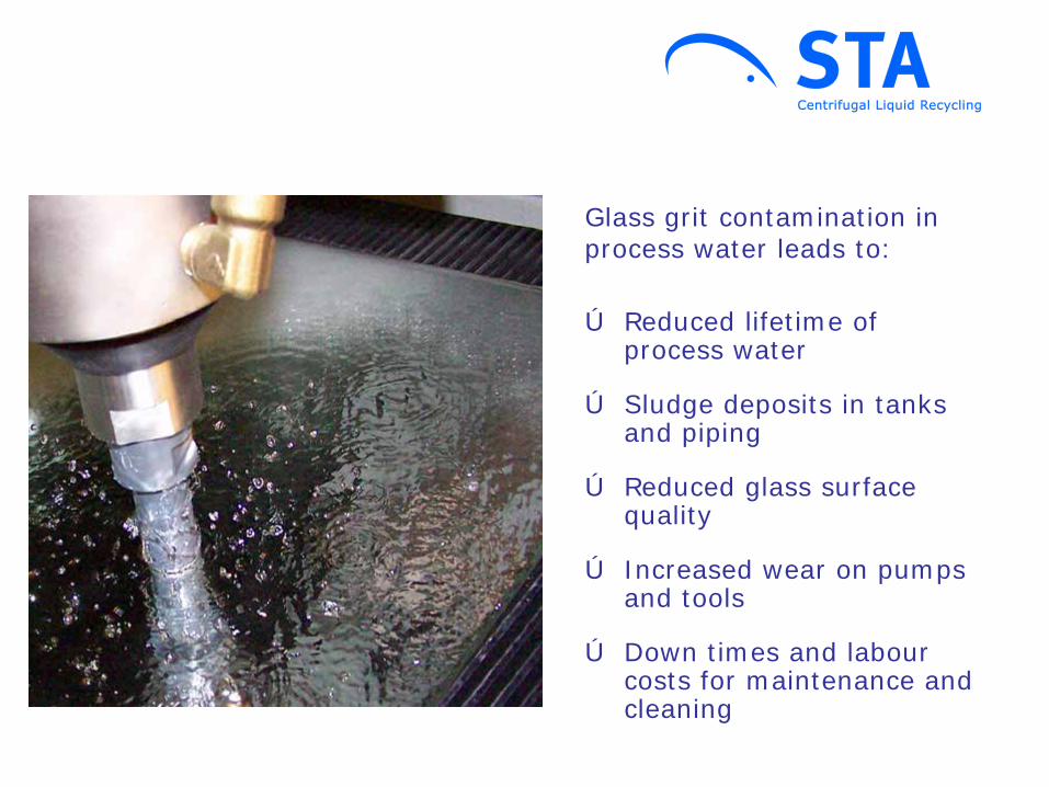
Ú Sludge deposits in tanks and piping
Glass grit contamination in process water leads to:
Ú Reduced glass surface quality
Ú Increased wear on pumps and tools
Ú Down times and labour costs for maintenance and cleaning
Ú Reduced lifetime of process water
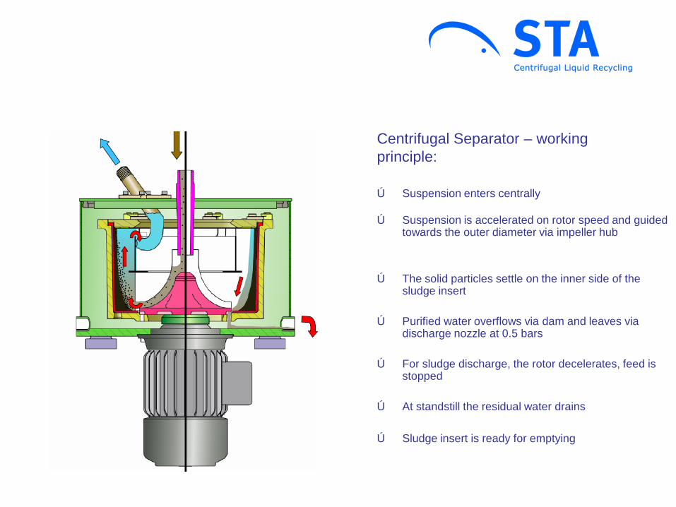
Centrifugal Separator – working principle:
Ú Suspension is accelerated on rotor speed and guided towards the outer diameter via impeller hub
Ú Suspension enters centrally
Ú The solid particles settle on the inner side of the sludge insert
Ú Purified water overflows via dam and leaves via discharge nozzle at 0.5 bars
Ú For sludge discharge, the rotor decelerates, feed is stopped
Ú At standstill the residual water drains
Ú Sludge insert is ready for emptying
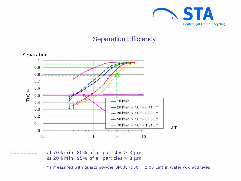
Separation Efficiency
µm
Separation
at 70 l/min: 80% of all particles > 3 µm at 20 l/min: 95% of all particles > 3 µm *):measured with quartz powder SF800 (x50 = 2,06 µm) in water w/o additives
3

Separator manual sludge emptying:
§ Open housing cover
§ Take out rotor cover
§ Take out filled sludge basket
§ Insert clean sludge basket
§ Remount in reverse order
Ú Procedure takes less than 3 minutes
§ Loosen rotor cover locking
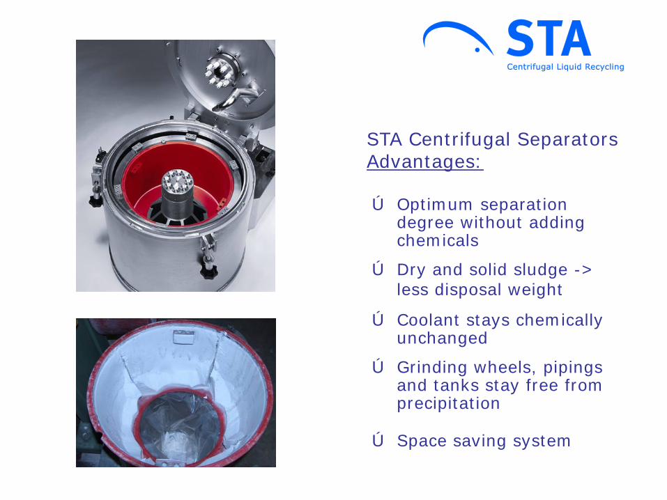
Ú Dry and solid sludge -> less disposal weight
STA Centrifugal Separators Advantages:
Ú Coolant stays chemically unchanged
Ú Grinding wheels, pipings and tanks stay free from precipitation
Ú Space saving system
Ú Optimum separation degree without adding chemicals
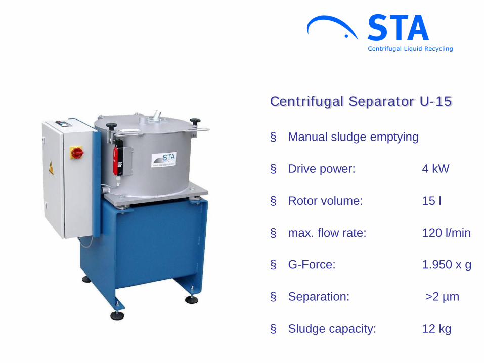
Centrifugal Separator U-15 § Manual sludge emptying
§ Drive power: 4 kW
§ Rotor volume: 15 l
§ max. flow rate: 120 l/min
§ G-Force: 1.950 x g
§ Separation: >2 µm
§ Sludge capacity: 12 kg

U-15
§ Fluid acceleration hub
§ Peeler nozzle -> 5m backflow pressure
§ Residual liquid drain -> dry sludge

NZ-50
§ Motor power: 1,5 kW
§ Rotor volume: 4,5 l
§ Max. flow rate: 50 l/min
§ Acceleration: 950 x g
§ Separation capacity: >5 µm
§ Sludge capacity: 6 kg

NZ-50
§ Direct drive
§ Free backflow of purified fluid
§ Compact design
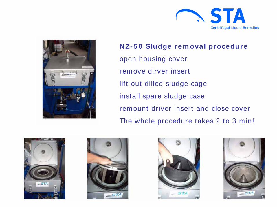
NZ-50 Sludge removal procedure
open housing cover
remove dirver insert
lift out dilled sludge cage
install spare sludge case
remount driver insert and close cover
The whole procedure takes 2 to 3 min!
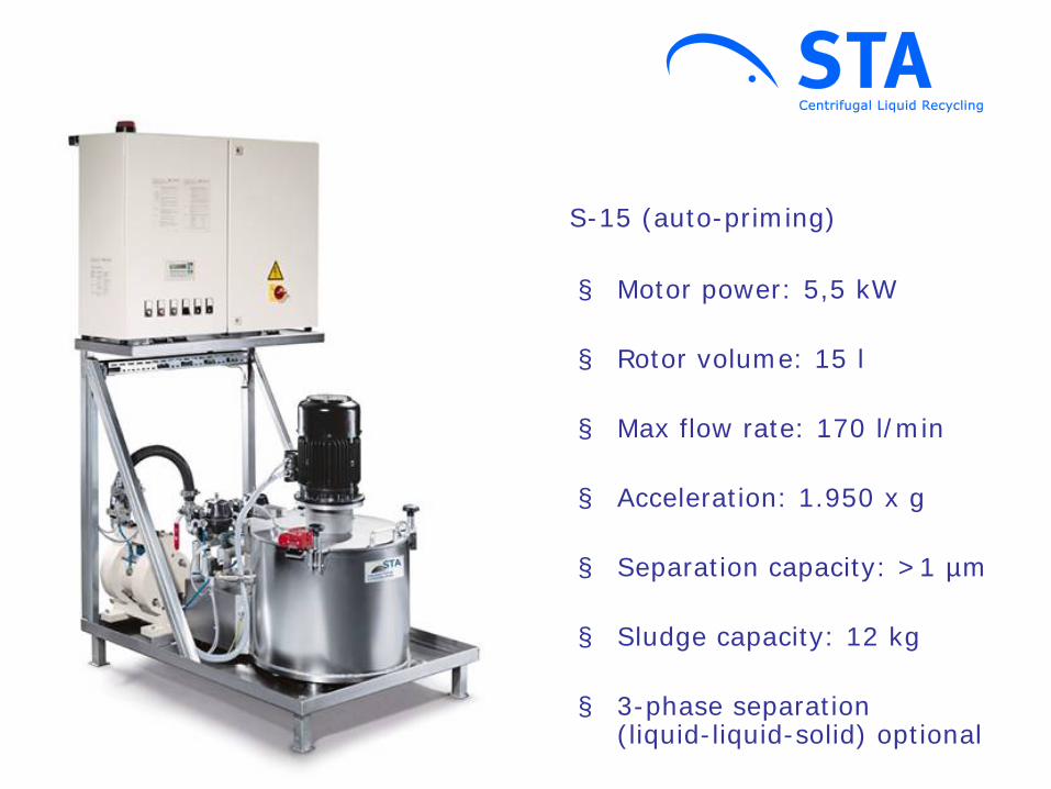
S-15 (auto-priming)
§ Motor power: 5,5 kW
§ Rotor volume: 15 l
§ Max flow rate: 170 l/min
§ Acceleration: 1.950 x g
§ Separation capacity: >1 µm
§ Sludge capacity: 12 kg
§ 3-phase separation (liquid-liquid-solid) optional

Auto-priming principle:
§ The separator sucks-in the liquid by means of its special accelerator hub via bottom entry
-> optimum liquid acceleration, maximum separation performance
§ At standstill residual liquid drains into
lower housing part and is sucked-in at re-start
-> no drain, machine can be placed directly on the ground
3-phase Separation (option): The secondary light liquid phase, e.g. tramp oil (red), is separated and picked-up via light phase peeler nozzle
S-15

AquaCyclone AC-1000
§ 1000 litres Cyclon Tank with precipitation enhancement
§ for direct connection of one or more glass working machines
§ recommended maximum flow rate 400 l/min (24 m³/h)
§ integrated lifting station, the machine’s flat tanks are obsolete
§ with machine supply pump, or alternatively easy integration of existing pump on site
§ anti-clogging and anti-wear suction connection for Centrifugal Separator
§ with large maintenance flange
§ minimum space requirement: footprint only 1 m x 1,75m
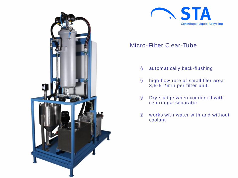
Micro-Filter Clear-Tube
§ automatically back-flushing
§ high flow rate at small filer area 3,5-5 l/min per filter unit
§ Dry sludge when combined with centrifugal separator
§ works with water with and without coolant
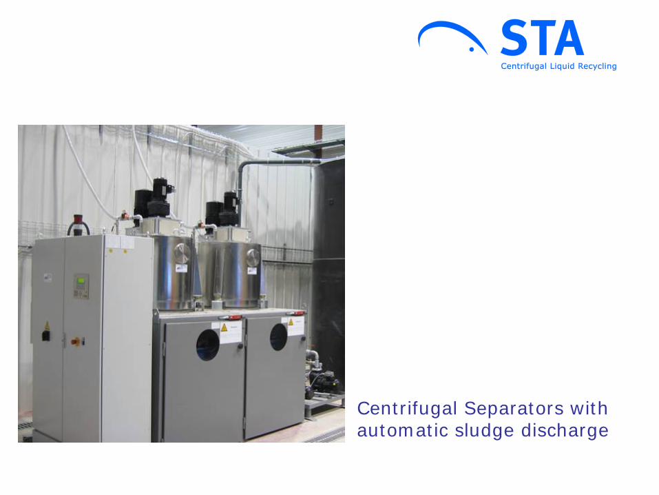
Centrifugal Separators with automatic sludge discharge

Working principle: 1. Separation à Liquid enters, is accelerated and centrifuged towards
the outer drum à On their way upwards, the particles, being heavier
then water, settle on the rotor wall à The purified water is picked up by the evacuation
nozzle and flows out at 0.5 bars 2. Drying à Rotor coasts à At 1.000 rpm the centrifugal valves open, and the
residual water is ejected à Sludge is dried
3. Sludge discharge à At standstill the magnetic clutch connects the gear
drive with the rotor shaft à The hub with its scrapers turns anti-clockwise while
the drum is blocked by the freewheel à Sludge is scraped-off and falls down into bin
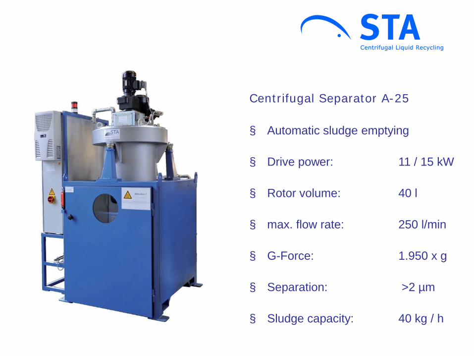
Centrifugal Separator A-25
§ Automatic sludge emptying
§ Drive power: 11 / 15 kW
§ Rotor volume: 40 l
§ max. flow rate: 250 l/min
§ G-Force: 1.950 x g
§ Separation: >2 µm
§ Sludge capacity: 40 kg / h

STA Central systems:
- Conical tanks for particle concentration by cyclone-effect
- Frequency-variator controlled supply of process water
- Continuous separation of dry and solid sludge
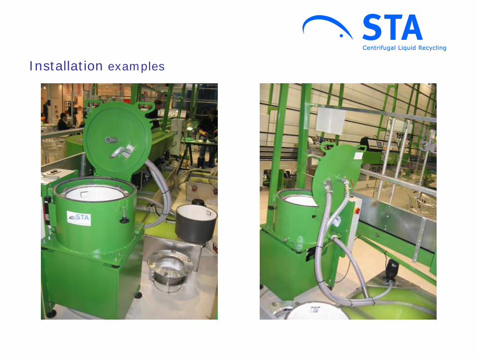
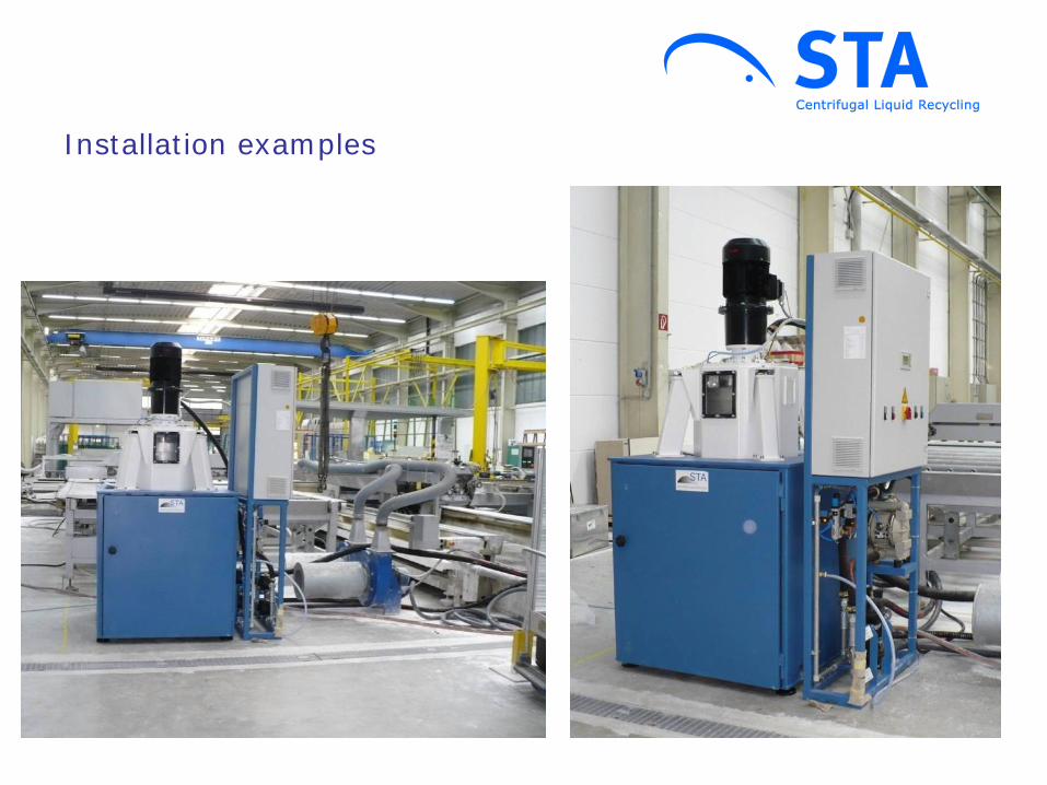
Installation examples

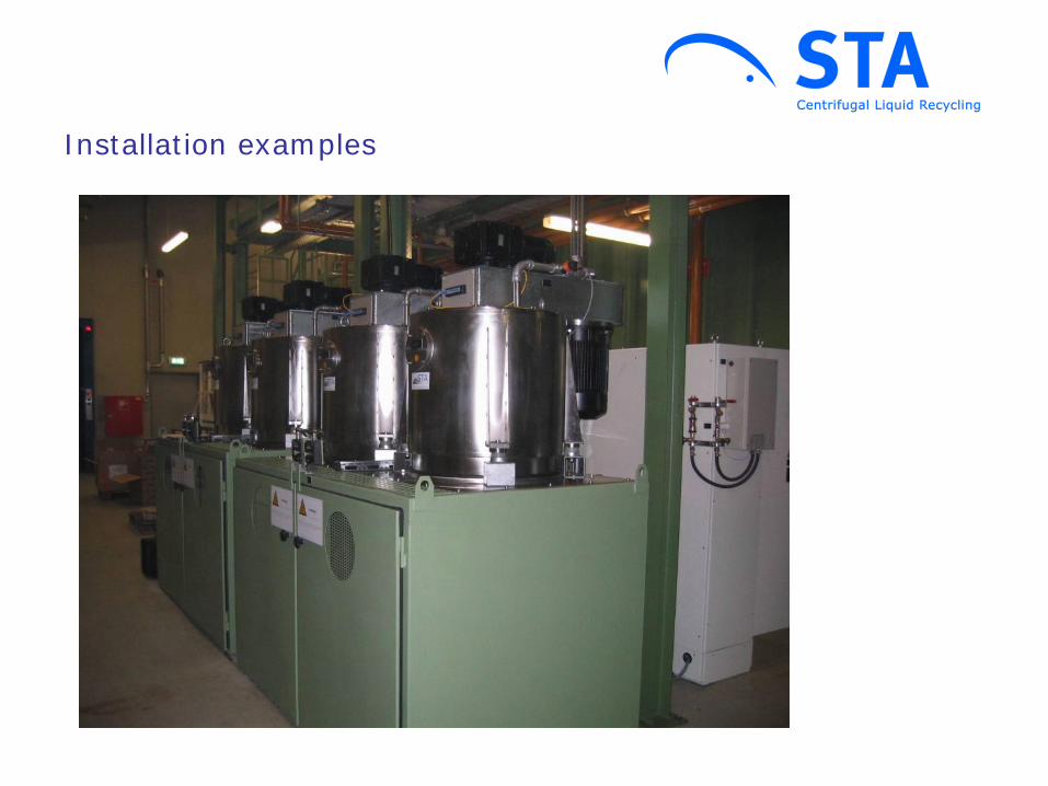
Installation examples
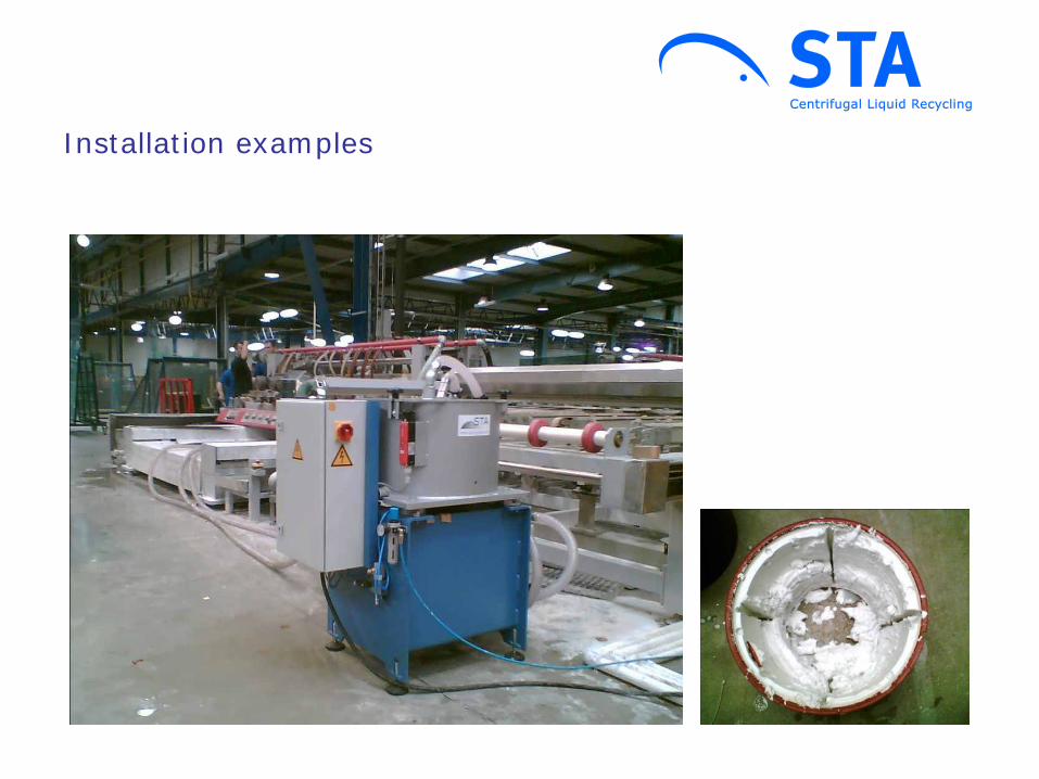
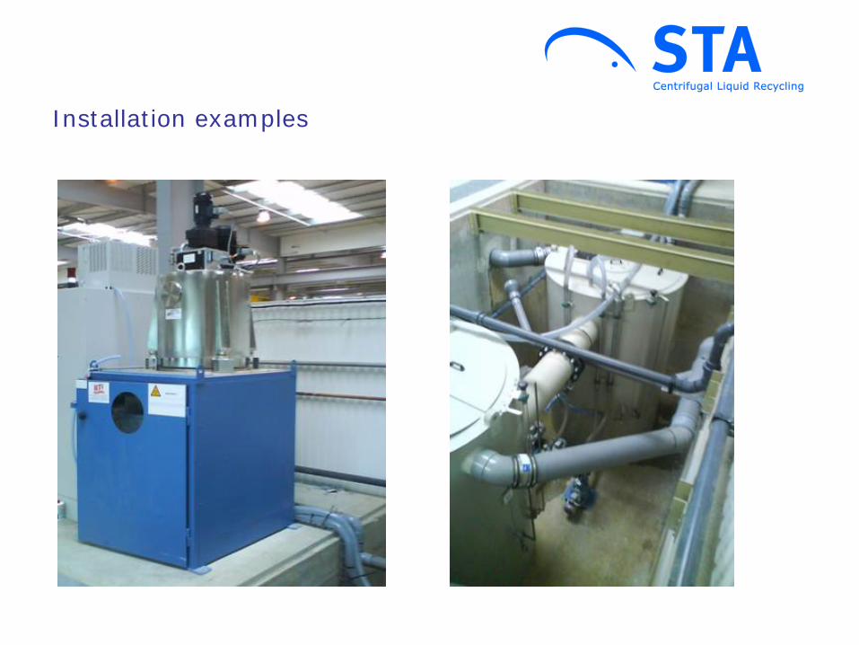
Installation examples

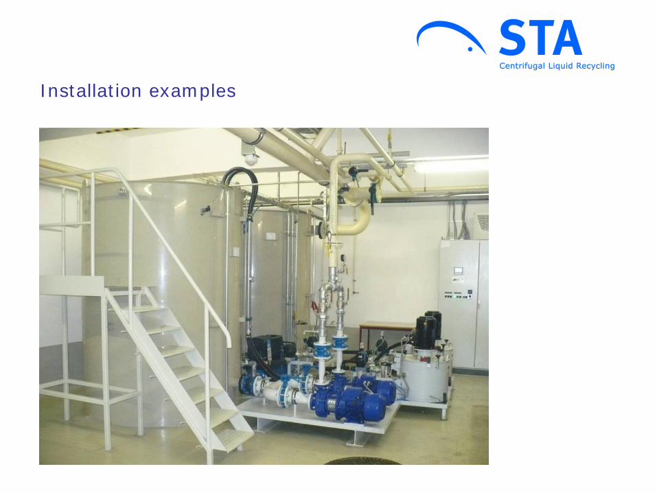
Installation examples
Installation examples
Installation examples
Installation examples
Installation examples

Contact: STA Separatoren-Technik & Anlagenbau GmbH Obere Giesswiesen 32 D-78247 Hilzingen Tel.: +49 (0)7731 / 9243-0 Fax: +49 (0)7731 / 9243-11 Email: [email protected] www.sta-separator.de