process modeling study of the cif incinerator (u)/67531/metadc667789/m2/1/high...predictions include...
TRANSCRIPT

- WSRC-MS-94-0655
Process Modeling Study of the CIF Incinerator (U)
by T. Hang Westing house Savannah River Company Savannah River Site Aiken, South Carolina 29808
DISCLAIMER
This report was prepared as an account of work sponsored by an agency of the United States Government. Neither the United States Government nor any agency thereof, nor any of their employees, makes any warranty, express or implied, or assumes any legal liability or responsi- bility for the accuracy, completeness, or usefulness of any information, apparatus, product, or process disclosed, or represents that its use would not infringe privately owned rights. Refer- ence herein to any specific commercial product, process, or service by trade name, trademark, manufacturer, or otherwise does not necessarily constitute or imply its endorsement, recorn- mendation, or favoring by the United States Government or any agency thereof. The views and opinions of authors expressed herein do not necessarily state or reflect those of the United States Government or any agency thereof.
\
A document prepared for 1995 SCS SIMULATION MULTICONFERENCE at Phoenix from 04/09/95 - 04/13/95.
DOE Contract No. DE-AC09-89SR18035
This paper was prepared in connection with work done under the above contract number with the U. S. Department of Energy. By acceptance of this paper, the publisher and/or recipient acknowledges the U. S. Government's right to retain a nonexclusive, royalty-free license in and to any copyright covering this paper, along with the right to reproduce and to authorize others to reproduce all or part of the copyrighted paper.
d U / V DlSTRtBUTiON OF T H E DOCUMENT IS UNLIMITED
DISCLAIMER
Portions of this document may be illegible in electronic image products. Images are produced from the best available original document.

a
WSRC-MS-94-0655
PROCESS MODELING STUDY OF THE CIF INCINERATOR (U)
by
T. Hang Westinghouse Savannah River Company Savannah River Technology Center Aiken, SC 29808
A paper proposed for presentation at the 1995 SCS Simulation MultiConference Phoenix, Arizona April 9-13,1995
and for publication in the proceedings of the meeting
This paper was prepared in connection with work done under Contract No, DE-ACO9 89SR18035 with the U. S. Department of Energy. By acceptance of this paper, the publisher
free license in and to any copyright covering this paper, along with the right to reproduce and to authorize others to reproduce all or part of the copyrighted paper.
and/or recipient acknowledges the U. S. Government's right to retain a nonexclusive, royalty- -
M
7r
PROCESS MODELING STUDY OF THE CIF INCINERATOR
T. Hang Westinghouse Savannah River Company
Savannah River Technology Center Aiken, SC 29808
e-mail: thong. [email protected]
3RDS: Environmental Science, Process-oriented, Risk Analysis.
ABSTRACT
The Savannah River Site (SRS) plans to begin operating the Consolidated Incineration Facility (CIF) in 1996. The CIF will treat liquid and solid low-level radioactive, mixed and RCRA hazardous wastes generated at SRS.
In addition to experimental test program, process modeling was applied to provide guidance in areas of safety, environmental regulation compliances, process improvement and optimization, A steady-state flowsheet model was used to calculate material1 energy balances and to track key chemical constituents throughout the process units. Dynamic models were developed to predict the CIF transient characteristics in normal and abnormal operation scenarios. Predictions include the rotary kiln heat transfer, dynamic responses of the CIF to fluctuations in the solid waste feed or upsets in the system equipments, peij5ormance of the control system, air inleakage in the kiln, etc. This paper reviews the modeling study peqormed to assist in the deflagration risk assessment.
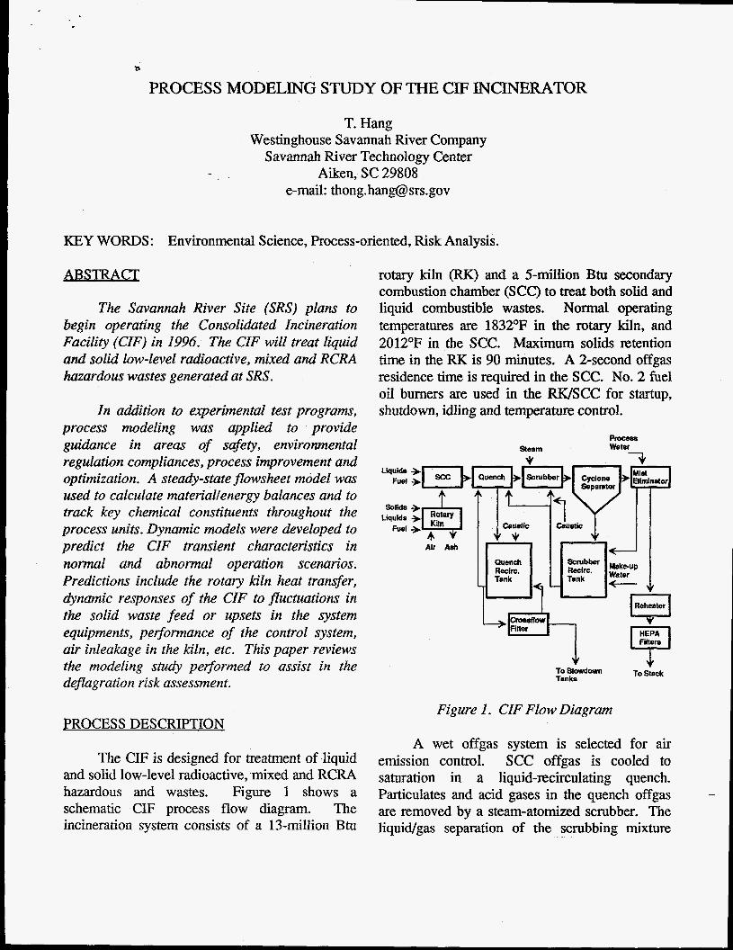
rotary kiln (FX) and a 5-million Btu secondary combustion chamber (SCC) to treat both solid and liquid combustible wastes. Normal operating temperatures are 1832°F in the rotary kiln, and 2012’F in the SCC. Maximum solids Rtention time in the RK is 90 minutes. A 2-second offgas residence time is required in the SCC. No. 2 fuel oil burners are used in the W S C C for startup, shutdown, idling and temperature control.
Liquids Fuel
Solids Liquids
Fuel
To Blowdown To Stack Tanks
Figure 1. CIF Flow Diagram PROCESS DESCRIPTION
The CIF is designed for treatment of liquid and solid low-level radioactive, mixed and RCRA hazardous and wastes. Figure 1 shows a schematic CIF process flow diagram. The incineration system consists of a 13-million Btu
A wet offgas system is selected for air emission control. SCC offgas is cooled to saturation in a liquid-recirculating quench. Particulates and acid gases in the quench offgas are removed by a steam-atomized scrubber. The liquid/gas separation of the scrubbing mixture

b
takes place in a cyclone separator. A mist eliminator removes entrained water droplets. Saturated scrubber offgas is reheated, and filtered through HEPAs prior to atmospheric dischkrge.
The CIF is currently under construction, and will begin operation in 1996. To support CIF startup and operation, the Savannah River Technology Center (SRTC) designs an extensive test program:
Metals Partitionin2 (Burns et al. 1994): Test burns were conducted using surrogate CIF wastes spiked with hazardous metals and organics. The primary test objective was to characterize the partition of metals between the kiln bottom ash, scrubber blowdown, and stackgas. Test data provided the required information for the successful treatment of secondary wastes (kiln ash and scrubber blowdown) to comply with Resource Conservation and Recovery Act (RCRA) disposal requirements.
Offgas Testing: The Offgas Components Test Facility (OCTF) is a 1/10 scale pilot plant that started operation in 1994. The OCTF evaluates the operating performance of the CIF offgas system.
m g : The RK is sealed at both ends by large (12 ft O.D.) rotary double-faced gas seals. These seals act as the primary barrier to the influx of air and the escape of gases and particles. A 2/5 scale seal with the same design and manufacturer was installed and tested.
In complement of the test program, mathematical modeling was applied to simulate various aspects of the incineration process: flow pattern, heat transfer, dynamic responses to fluctuations in the feed or upsets in the system equipment, speciation of heavy metal traces. Simulation results of the CIF process dynamics
were presented elsewhere (Hang 1992). This paper focuses on the modeling study of deflagration.
DEFLAGRATION STUDY
The National Fire Protection Association (NFPA) requires incineration systems use either a relief device or other methods to control pressure surges. This study was part of a system evaluation and design effort to ensure the CIF met the intent of the NFPA code 82.
Deflagration is a concern if an accidental power loss occurs during nonnal operation causing burner flameout and loss of all fans except one induced-draft (ID) fan. Rubber present in the solid waste charge decomposes into flammable isoprene vapor which is burned when the rotary kiln temperature remains above the autoignition temperature (AIT) of isoprene. As the kiln cools below the isoprene AIT (743OF), continuing generation of isoprene may form a flammable mixture with a concentration above the lower explosive limit GEL) thereby causing ignition by contact with a local hot spot. In an explosion event, the RK pressure may exceed the allowable internal kiln pressure of 15 psig.
An explosion risk assessment of the CIF rotary kiln and SCC was performed by SAIC and PLC in 1992. In the event of power outage, all combustion air fans stop functioning, and the only source of air flow is an ID fan. Information on the kiln air inleakage flow is required to provide a solid basis for verification of the assessment conclusions. The objective of this study is to estimate the kiln air inleakage rate and to predict the kiln temperature profile based on the calculated air flow rate.
MODEL DEVELOPMENT -
A Fortran model was developed based the CIF design shown in Figure 2. Figure 2 illustrates

-5
the arrangement of forced-draft (FD) fans and Grothm back-draft (BD) dampers. The FD fans provide combustion air required for burning 0
solifliquid wastes and supplemental No. 2 fuel oil in the RK/SCC. For contamination control, 0
the BD dampers prevent flow outleakage in case of a pressure excursion in the system. The ID fans are necessary to maintain the system negative pressure.
0
0
0
Note that if the pressure difference across a BD damper is less than the damper pressure
leakage. setting, the damper remains closed causing no air 0
48.0
Air inleakage only occurs through the idle combustion air fans. Automatic restart of the ID fan(s) using a backup diesel generator. All dampers are failed-open. No flow recirculation around the ID fan in operation. Except in the quench and scrubber/cyclone, system temperatures remain unchanged. This is because temperature change requires much longer time than pressure. Off-gas temperature upstream of the
60 HP Solids Comb. kr
Eliminator
Fan - 6,525 #/hr
Fan - 11,025 Whr
** DUCTSIZES 0 3 Fans Q 12,000SCFM each Q26 Inch (WC Inlet press & 44.71 Inch outlet press)
Figure 2. CIF Process Fan and Duct Sizes
The current BD damper settings are listed beside each damper in Figure 2.
AssumDtions
The following assumptions were made in deriving the equations for the air inleakage calculations:
HEPA filters is above the dew point. This assump tion eliminates condensation of gas when passing through the HEPA filters, since any filter plug will prohibit air flow through the system.
-
5
Process Parameters
Effects of the following parameters on the FX inleakage rate were investigated:
e
e
e
Scrubber steam: Steam injection changes the pressure difference across the scrubber /cyclone, which effects the total air flow. Solids burning: The combustion product gas released by the solids burning raises the kiln pressure, thereby lowering the amount of air inleakage. Number of BD dampers in operation: Kiln total air flow is dependent on the number of inleakage sources in the W S C C ( i.e., number of BD dampers). Kiln temperature: Inleakage is expected to increase at lower temperatures due to vapor contraction.
Methodologv
The CIF air inleakage was modeled in this manner: Pressure loss in each vessel and the piping was calculated from the concept of effective equivalent conductance. The RK pressure was obtained from the dynamic mass balance combined with ideal gas equation. The scrubber/cyclone pressure drop/rise was estimated by a correlation provided by the vendor. Pressure drop across a centrifugal F D fan was derived from the Bernoulli equation for the two types of fan vanes used in the CIF @e., radial curved or straight, and backward curved).
Initial conditions prior to the power loss were based on the design base case.
RESULTS
Several cases were calculated to account for effects of process parameters on the RK air inleakage: with and without 10,000 lb/hr scrubber steam; with and without solids burning. The
following conclusions were drawn from these calculations:
e
The results show that during the power loss air leaks into the kiln through the combustion air fans at a total rate of 11,000 I b h (no scrubber steam injection) or 12,000 l b b (with 10,000 lb/hr scrubber steam injection). Stoichiometric air required to burn a 72- Ib solid waste batch in 20 minutes was previously estimated about 6,000 lb/hr. Solids burning did raise the kiln pressure and lower the kiln total air inleakage; however, the effect of solids burning is small even when a maximum and steady burning rate was used in the calculations. Kiln air inleakage can be increased by increasing the open pressure settings of the BD dampers in the SCC.
Decreasing kiln temperture lowers the offgas temperature at the SCC exit; consequently, less water evaporates in the quench. Since the ID fan pulls through the system at approximately a constant gas flow rate, more air leaks into the W S C C to compensate for the lesser amount of water evaporation in the quench. Therefore, the kiln air leakage rate increases with decreasing kiln temperature. Moreover, the leakage rate can only increase when the kiln pressure decreases (i.e., more vacuum in the kiln).
Assuming the SCC temperature is 200°F higher than the kiln temperatm, the kiln air leakage rate was calculated for kiln temperatures ranging from 400'F to 1832°F. The results are plotted in Figure 3 for the two cases (i.e., with and without scrubber steam, no solids burning). In Figure 4, kiln pressure is plotted vs. kiln temperature for the same cases.

a
A 25000
A
f * A 2=
3 * A
- A
-1, ; 20000 - c
d 0 . L a, O b
m Y W * A
J O A
* A O A
* A 15000 -
.- L A A
0 a : Without Scrubber Steam e
. A WithScrubberSteam
1 0 0 O O i ~ . . . . I . . , . , - . . , . . . - 0 500 1000 1500 2000
Kiln Temperature (OF)
Figure 3. Kiln Air Leakage Rate
* * Without Scrubber Steam
A With Scrubber Steam A A
* A A
...A O A
- A
-2.7
-2.8 0
5 v
-2.9
f (1 E -3.0 ~ . , . o ~ : e :=A. , . , . , . . C -
-3.1 A
A
-3.2 0 500 1000 1500 2000
Kiln Temperature (OF)
Figure 4 . Kiln Pressure
Kiln Cooldown
The CIF dynamic model previously developed (Hang 1992) was applied to obtain the kiln cooldown temperature profile during the power loss event. The model simulated the phenomenon in two stages:
Normal operation prior to the power loss - To establish the CIF normal operating condition, the design base case was selected, in which every 4 minutes approximately 48 lbs of solid
waste was inserted into the kiln. The normal operation was simulated for 12 minutes.
Power loss - When a 72-lb charge of solid waste was introduced into the kiln, the system power failed. All burners and combustion air fans ceased to function. A 20-minute burn time was selected.
In the simulation, the calculated kiln air inleakage rate and kiln pressure as function of temperature as shown above were used. Figure 5 shows the result of the kiln temperature vs. time. The kiln temperature is predicted to remain above the isoprene AIT for about three hours.
2000
G 0, 1500 - c ; E g $000-
E 8 C - 500
O + 0
Without Scrubber Steam I -
Power Loss I___)
. - 1 2 3 4
Time (hr)
Figure 5. Kiln Cooldown
To better cope with a possible power-loss event, the CIF control logics were revised. The new control strategy allows the RK pressure to be controlled at a desired setpoint during a power loss. Since the kiln air leakage rate primarily depends on the difference of ambient pressure and kiln pressure, control of the kiln pressure ensures’ sufficient air available in the kiln for burning the remaining solid wastes. Without kiln pressure control, the air inleakage rate increases with decreasing kiln temperature, and causing a fast
-

s
kiln cooldown. With kiln pressure control the air leakage rate remains constant resulting in a slower and more desired kiln cooldown.
Based on this new scheme the air inleakage rate was recalculated. - The -2.7’WC pressure setpoint was selected resulting in a kiln air leakage rate of approximately 11,100 1bh.r (with scrubber steam injection, no solids burning). The cooldown simulation predicts that after four hours the kiln temperature decreases to 790’F. The result is shown in Figure 6 below.
2000
G L 1500
z i? 3 c
g 1000
!ii I- C - y 500
0 1 2 3 4
Time (hr)
Figure 6. Kiln Cooldown (Kiln Pressure Controlled @ -2.7’WC)
CONCLUSIONS
This study shows that without kiln pressure control the air inleakage rate increases with decreasing kiln temperature, thereby accelerating the kiln cooldown. With kiln pressure control the air leakage remains constant resulting in a slower and more desired kiln cooldown. The air leakage can be increased or decreased by selecting the appropriate kiln pressure setpoint.
The results indicate that during the power loss event air leaks into the RK through the combustion air fans at an initial total rate of 11,000 lb/hr (without scrubber steam injection) or
12,500 lb/hr (with 10,000 scrubber steam injection). Control of the kiln pressure at -2.7 ‘WC results in a constant air leakage of 11,100 lb/hr, These rates exceed the 6,000 lb/hr stoichiometric air required to burn a 72-lb batch of solid wastes in 20 minutes. The kiln temperature remains above the isoprene AIT (743°F) for approximately fours hours (Le., long after all solids had been burned), therefore eliminating any possible deflagration during the power outage.
REFERENCES
Burns, D.B.; H. Holmes Burns; M.G. Looper; and G.R. Hassel. 1994. “Metals Partitioning in a Rotary Kiln Incinerator with a Wet Off-Gas System.” In Proceedings of the 1994 International Incineration Conference (Houston, TX, May 9-13). The Regents of the University of California, Irvine, CA, 527-53 1.
Hang, T. 1992. “Dynamic Simulation Study of the CIF Incinerator.” In Proceedings of the 1992 Incineration Conference (Albuquerque, NM, May 11-15). The Regents of the University of California, Irvine, CA, 679-682.
Science Applications International Corporation (SAIC) and Professional Loss Control, Inc. (PLC). 1992. “Explosion Risk Assessment of the Consolidated Incineration Facility Rotary Kiln and Secondary Combustion Chamber.” Technical Report WSRC-TR-92-384. Westinghouse Savannah River Company, Aiken, SC.
ACKNOWLEDGEMENT
The information contained in this paper was developed during the course of work done under Contract No. DE-AC09-89SR18035 with the U.S. Department of Energy.