process management
TRANSCRIPT

Process Management
COMP 229 (Section PP) Week 8
Prof. Richard ZanibbiConcordia University
March 6, 2006

2
Last Week...
Basic OS Functions (pp. 89-94)1. Device Management2. Process and Resource Management3. Memory Management4. File Management
Implementation Issues (pp. 94-103)Processor ModesKernelsRequesting OS ServicesSoftware Modularization
Contemporary OS Kernels (pp. 104-110)UNIX KernelsWindows NT Executive Kernel
system call vs. message passing
...or not.
Supervisor vs. User:controls available instructions,
memory(“user space” vs. “system space”)
A Monolithic Kernel
Based on Microkernel approach
Only Kernel Code Executed in Supervisor Mode
Note: different definitions exist for “OS functions”

3
Process, Thread, and Resource Management
Implements Abstract Machines...including scheduling processes/threads and managing
their associated resources– usually implemented as a single module, defining the
abstract machine environment as a whole– If OS allows threaded processes, then processes and
threads must be managed separately
Resource Manager– Allocates and book-keeps available and utilized
resources– Change in resource often related to change in a
process: so resource management often discussed as part of process management

4
Process, Thread, and Resource Management, Cont’d
Process Manager–Provides multiple abstract machines (execution
contexts)–Allows multiple users, processes and/or
threads to share the processor Key issue: how will processor time be allocated
between processes?

5
This Week...Process Management
Managing Classic and Modern Processes (pp. 199-206)ResourcesProcess Address SpaceOS Families
The Hardware Process (pp. 206-208)
Abstract Machine Interface & Implementation (pp. 208-225)Process and Thread AbstractionsExecution StatesResource Management
Generalizing Process Management Policies (pp. 226-228)

Managing Classic and Modern Processes
(pp. 199-206)
7
The Process Manager
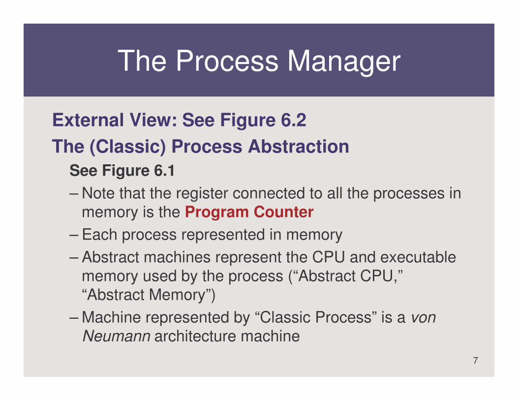
External View: See Figure 6.2The (Classic) Process Abstraction
See Figure 6.1– Note that the register connected to all the processes in
memory is the Program Counter– Each process represented in memory– Abstract machines represent the CPU and executable
memory used by the process (“Abstract CPU,” “Abstract Memory”)
– Machine represented by “Classic Process” is a von Neumann architecture machine

8
The Modern Process Abstraction(Fig 6.3)
Modern Process Abstraction–Abstract machines now simulate
multiprogramming machines on which threads run
–Abstract machines simulate multiprogramming for threads

9
User Space Threads vs.Kernel Threads
User Space ThreadsClassic processes are time-multiplexed Thread library simulates multiprogramming within the
abstract machine (in user space)e.g. Mach C, POSIX thread libraries
Kernel ThreadsThread execution is time-multiplexed (not processes)
• when one thread blocks, other threads in process can executeOS manages processes and threads separately (process
becomes a passive context)e.g. Windows, (Modern) Linux

10
Process Address Space
DefinitionCollection of addresses (bytes) a thread can referenceModern OS: fixed size (232 for 32-bit machines, 4 GB)
Represented in Address Space:Executable Memory Locations
• as bound (assigned) by the memory resource managere.g. containing program, data, thread states, thread stacks
Memory-mapped resources• as bound by resource managers (if resource policy permits)• some resources cannot be mapped (e.g. processor)e.g. in some OS’s files may be represented in the address space
11
Address Space, Cont’d
SuggestionCompare this new view of the address space to
the one presented in Week 6, where only the thread states, stacks, program, and data are represented in the address space
Visualizing the Process Address SpaceSee Figure 6.4Note: new processes and threads data (state,
stack) also mapped into the address space

12
OS Families
OS FamilyA group of OS’s that share a common system call
interface (i.e. abstract machine model)
UNIX FamilyImplement POSIX.1 e.g. Linux, OpenBSD, FreeBSD, MacOS X
Windows FamilyImplement subsets of the Win32 APIe.g. Windows 95/98/ME, NT/2000/XP, CE (“Pocket PC”)

The Hardware Process
(pp. 206-208)

14
The Hardware Process and Scheduling
DefinitionThe sequence of instructions physically executed by the
computer’s CPU
Process Scheduler (part of Process Manager)– Allocates processes (abstract machines) for simulation
within the hardware process– Switches between threads/processes made by altering
the Program Counter register, set by:• scheduler actions, traps (system calls), interrupts

15
The Initial Process and the Idle Thread/Process
OS Initialization– Process, thread, resource descriptors initialized– Initial process with single thread created
• process and thread descriptors are initialized
Initial Process – The first process created; root of process hierarchy– Spawns another thread or process, which does nothing
(executes an empty loop); if executed, soon interrupted. This is the idle thread or idle process
– Idle thread chosen by Process Scheduler only when there is no ready thread in the system

16
Tracing the Hardware Process
Figure 6.5Note that execution keeps returning to the
process manager: this is necessary for keeping processes properly synchronized

17
Abstract Machine Interface
Processor Modes, RevisitedUser: instructions that do not affect resource sharing
modelsSupervisor: instructions that are used to implement
robust resource sharing models
Abstract Machine Instruction Set User mode instructions + System Calls (Kernel Fns)See Fig 6.6, Tables 6.1 and 6.2
Traps, Also Revisited...– OS systems calls in the Abstract Machine Interface– When called, code in OS kernel executed in supervisor
mode

18
Example: Compiling a C Program to Use an Abstract Machine Interface
C Program...a = b + c;pid = fork();...
Compiled machine user instructions:...// a = b + cload R1,bload R2, cadd R1, R2store R1, a// now do the system calltrap sys_fork...
User mode machine instructions
System call (OS executes privileged instructions)

Abstract Machine Interface & Implementation
(pp. 208-225)

20
Context Switching
DefinitionChanging the process (abstract machine) to simulate in the
hardware process • Performed by the Process Scheduler (in Process Manager)
Context Switches Occur for...– process/thread system calls– device interrupts
*Process states are recorded in the Process Descriptor for each process
See Figure 6.7: try tracing the arrows in order

21
Process CreationProcess Descriptor Initialization by the Process Manager:
– process descriptor is initialized– address space is created
• program addresses bound into address space• memory-mapped resources bound into address space
– additional resources represented in process descriptor, fields set to reflect allocated resources
– base thread created• classic process: represented in process descriptor• modern process: threads have separate descriptors
Process Descriptor Fields Used to:Manage address spaceCoordinate thread execution, record execution state (e.g. registers)Book-keep allocated and requested resourcesSupport protection/isolation and sharing of resources

22
Process Descriptors, Cont’d
See Table 6.3Note that in Table 6.3, this is a partial list of
process descriptor fieldsExample process descriptors in Linux, Windows
outlined in pp. 214-216
See Figure 6.8Note: kernel implements thread scheduling,
interrupt handling; NT Executive implemented on top of the NT kernel

23
Thread Management
As Part of Process Management– Specifically, the thread management algorithm– Tasks: create, destroy, manage thread resources, scheduling and
switching threads– Thread resources (e.g. stack, state) are bound into the associated
process’ address space
Thread Descriptor (See Table 6.4)Another “book-keeping” data structure for the Process ManagerManages thread-specific resources and state information (e.g.
process resources not represented)
Linux: threads implemented via alteration of “forking” method; thread descriptor is a modification of process descriptor type
Windows: thread descriptors combine Kernel and Executive components, as for processes

24
Process and Thread States(as seen in the Process/Thread Descriptors)
PurposeIndicate execution and resource request status for thread/process
1. “Running” StateProcess/thread is allocated to the processor (running in hardware
process)
2. “Blocked” StateProcess/thread is waiting for a resource
3. “Ready” StateProcess is ready to run; on entry to this state, requests
scheduling by the Process Managere.g. after initialization, or after a resource has been allocated

25
Example State DiagramsSimple State Diagram (Fig. 6.10)
– Requesting unavailable resource blocks process– Resource becoming available sets process state to “Ready”– Requests for available resources don’t block process
UNIX Process State Transition Diagram (Fig. 6.11)Note: “blocked” state now has three different types:
• uninterruptible sleep: blocked for I/O • sleep: blocked for some other resource• traced/stopped: parent process has sent a signal to stop the process
(e.g. in debuggers)“Zombie:” process has finished, but has not returned to the parent
process (prevents data loss!)• In Zombie state, resources are still held for the process• On exiting Zombie state, resources released, process descriptor
erased

26
Resource Managers(See Fig. 6.12)
Mechanism Component“Generic”, components present in all resource managers
Policy ComponentResource-specific behaviour
Resource Descriptors (See Table 6.5)Records state of the resource, including available units, and total
number of units in the system (for reusable resources)
...and Process StateResource managers alter process as well as resource descriptors
when resources are allocated to a process • e.g. changes state of “blocked” process to “ready”
27
Reusable and Consumable Resources
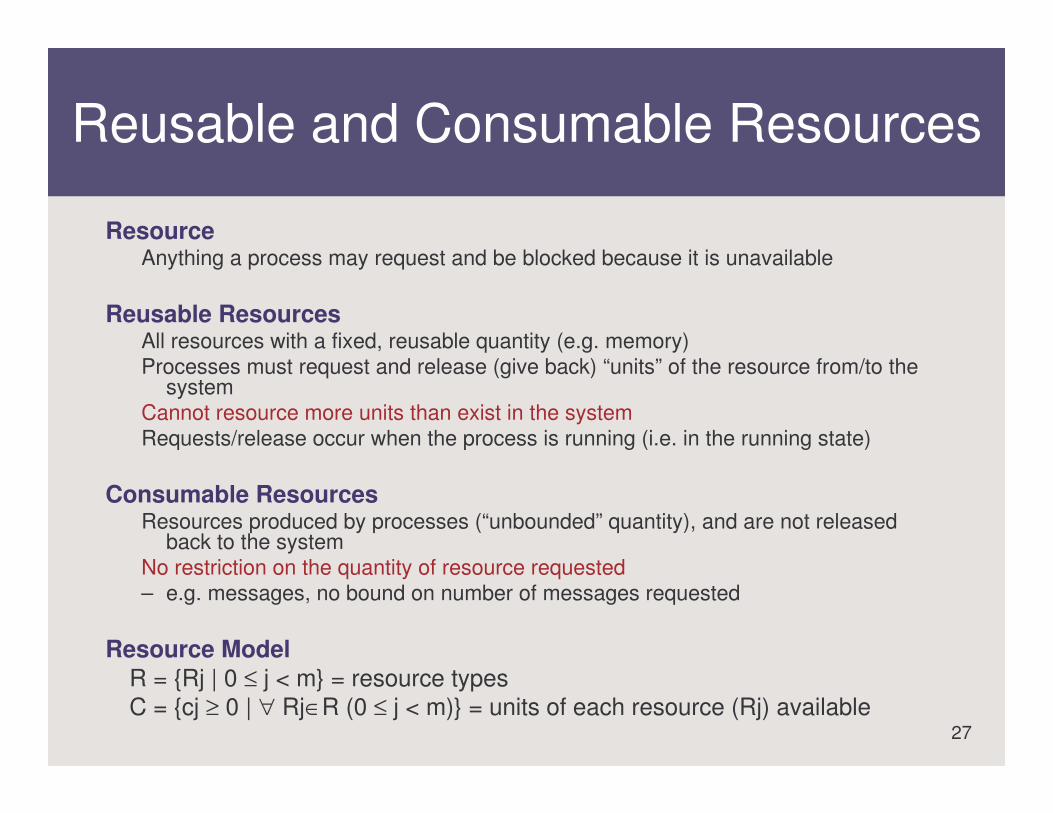
ResourceAnything a process may request and be blocked because it is unavailable
Reusable ResourcesAll resources with a fixed, reusable quantity (e.g. memory)Processes must request and release (give back) “units” of the resource from/to the
systemCannot resource more units than exist in the systemRequests/release occur when the process is running (i.e. in the running state)
Consumable ResourcesResources produced by processes (“unbounded” quantity), and are not released
back to the system No restriction on the quantity of resource requested– e.g. messages, no bound on number of messages requested
Resource ModelR = {Rj | 0 ≤ j < m} = resource typesC = {cj ≥ 0 | ∀ Rj∈R (0 ≤ j < m)} = units of each resource (Rj) available

28
Resources and Process Termination
Reusable ResourcesReleased from the terminating process, made
available for allocation to other processes
Consumable ResourcesAssumed to be “consumed” by associated
processLost on process termination

Generalizing Process Management Policies
(pp. 226-228)

30
Initial Process
Login Shell 3Login Shell 2Login Shell 1
Bash Shell
Email Program
Sibling Processes
Parent Process of Child Processes of
Web Browser
Process Hierarchy(started by Hardware Process)

31
State Diagram Generalization
See Fig. 6.14 (Compare with Fig. 6.10)– Blocked, Ready states have been split to allow
parent processes to place children in a “suspended” state
• (similar to “trace” state in Unix state diagram)
– Also added: a “Yield” edge, where a process voluntarily allows another process to run
– We looked briefly at the Windows NT Thread State Diagram: blocked and ready states also split in that diagram.
32
Further Generalizations of the Process Hierarchy
RC 4000– An early instigator for microkernel-based systems– Nucleus: implements fundamental resource
management mechanisms (“microkernel”)– Resource policies implemented by processes– Children created from nucleus process
• each was a special-purpose OS implementing a resource policy
• allowed simultaneous real-time, batch, and timesharing-based scheduling
• Resources allocated by parent process: not the OS– Allows very flexible process hierarchies (more than
Unix, for example)

33
Next Week...
File ManagementPart II, Chapter 13, pp. 514-544