process instrumentation-field instruments for ... - · pdf filefield instruments for process...
TRANSCRIPT
Field Instruments for Process AutomationJuly 2012 Supplement
Process Instrumentation

IntroductionThe Process Instrumentation & Analytics Business Segment of Siemens Industry, Inc. is a leader in providing innovative solutions to process instrumentation and control challenges. It is the operational center for Siemens’ process instrumentation and control business in North America. The Process Instrumentation business provides a complete line of reliable measurement and control products, including: transmitters for level, pressure, temperature, and flow; loop controllers; valve instrumentation products, regulators and relays; process protection instruments; weigh feeders and belt scales. Siemens Process Instrumentation solutions help increase productivity and plant safety, reduce time-to-market and improve product quality across the process industries, such as chemical, pharmaceutical, bio-pharmaceutical, oil & gas, water and wastewater treatment, mining, pulp & paper and refining.
This catalog supplement includes only those items manufactured in Spring House, sold here in the US, and not covered in the Siemens Field Instruments FI 01 catalog. If you do not find the product you are looking for in this supplement, please contact our factory for more information. We will be happy to connect you with a sales representative in your area that covers the products and services that you need.
Siemens Industry, Inc.Process Instrumentation1201 Sumneytown PikePO Box 900Spring House, PA 19477215-646-7400
1
1.1
Siemens Industry, Inc. assures no liability for errors or omissions in this and any attached documents or for the application and use of information included in this and any attached documents. The information herein is subject to change without notice.

Table of ContentsIntroduction ..........................................................................................1.0 Introduction .......................................................................................................... 1.1 Table of Contents ................................................................................................ 1.2
Control Solutions ................................................................................2.0 Controllers ........................................................................................................... 2.1 Model 353 Process Automation Controller .............................................................. 2.1 i|config™ Controller Configuration Utility ................................................................. 2.6 Model 353 Ethernet Remote I/O .............................................................................. 2.7 i|ware OPC Server ................................................................................................... 2.9 i|ware for 353 Series Controllers .............................................................................. 2.10 i|station for 353 Series Controllers ........................................................................... 2.12
Valve Control Products .......................................................................3.0 Valve Positioners ................................................................................................ 3.1 Series 760 P/E Valve Positioner .............................................................................. 3.1 Series 73 Built-In Valve Positioner ........................................................................... 3.7 Series 74 Valve Positioner ....................................................................................... 3.9
Transducers ........................................................................................ 3.12 Models 77 and 771 Current-to-Pneumatic Transducers ......................................... 3.12
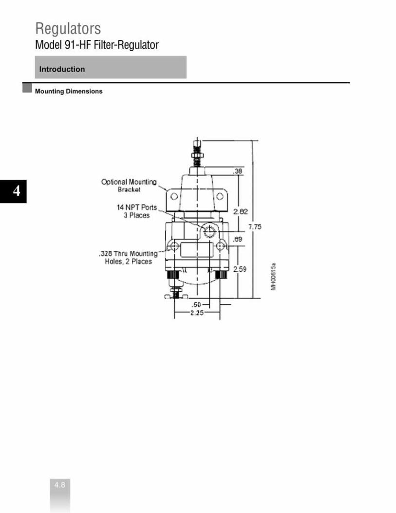
Regulators and Relays ....... ................................................................ 4.0 Regulators ............................................................................................................ 4.1 Models 40, 41, and 42 Precision Pressure Regulators .............................................4.1 Model 91-HF Filter-Regulator ...................................................................................4.7 Model 2306 Instrument Air Filter...............................................................................4.9
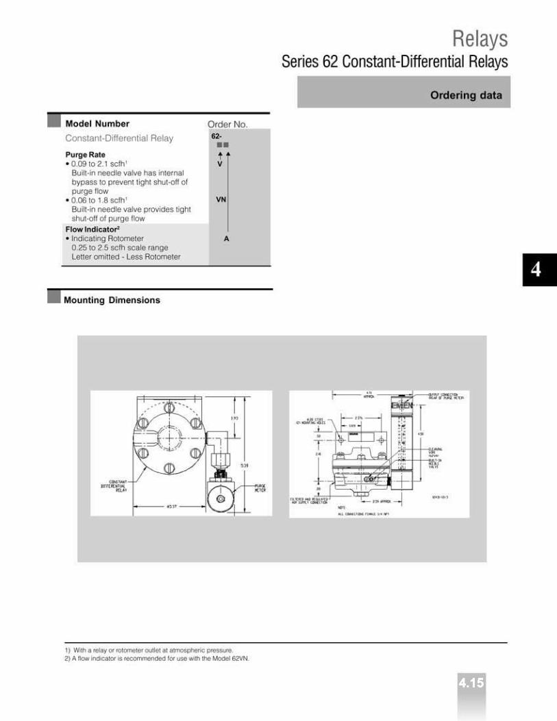
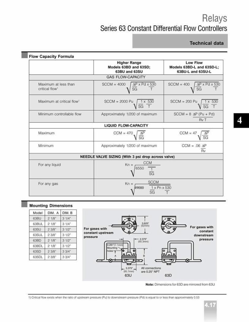
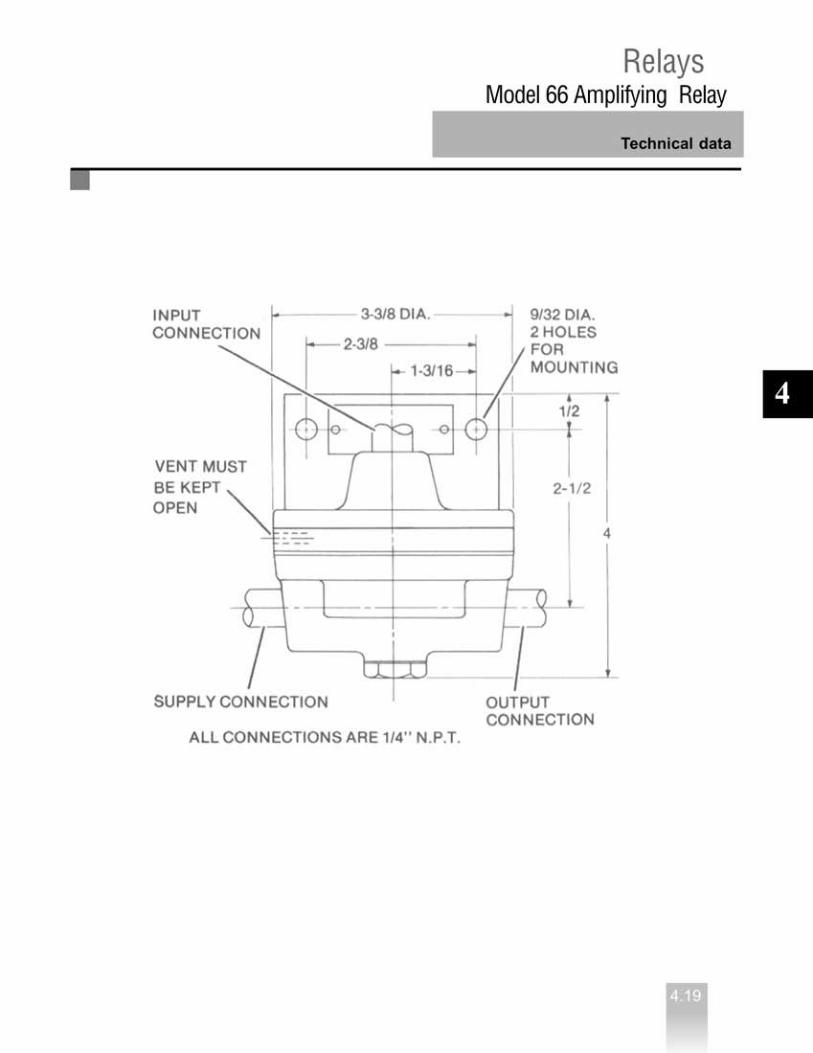
Relays .................................................................................................................... 4.10 Series 61 Booster Relays .........................................................................................4.10 Series 62 Constant-Differential Relays .....................................................................4.14 Series 63 Constant Differential Flow Controllers ......................................................4.16 Model 66 Amplifying and Reducing Relays ..............................................................4.18 Model 661 Amplifying Relays with Bias ....................................................................4.20
1.3
1
2.1
2
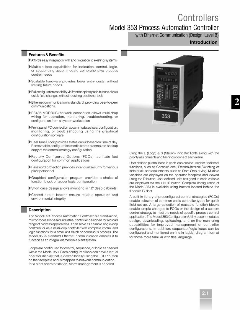
ControllersModel 353 Process Automation Controller
with Ethernet Communication (Design Level B)Introduction
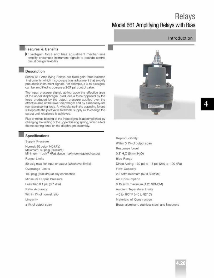
Features & BenefitsAffords easy integration with and migration to existing systems
Multiple loop capabilities for indication, control, logic,or sequencing accommodate comprehensive processcontrol needs
Scalable hardware provides lower entry costs, withoutlimiting future needs
Full configuration capability via front faceplate push-buttons allowsquick field changes without requiring additional tools
Ethernet communication is standard, providing peer-to-peercommunications.
RS485 MODBUS® network connection allows multi-dropwiring for operation, monitoring, troubleshooting, orconfiguration from a system workstation
Front panel PC connection accommodates local configuration,monitoring, or troubleshooting using the graphicalconfiguration software
Real Time Clock provides status ouput based on time of day.Removeable configuration media stores a complete backupcopy of the control strategy configuration
Factory Configured Options (FCOs) facilitate fastconfiguration for common applications
Password protection provides individual security for variousplant personnel
Graphical configuration program provides a choice offunction block or ladder logic configuration
Short case design allows mounting in 12" deep cabinets
Coated circuit boards ensure reliable operation andenvironmental integrity
Description
The Model 353 Process Automation Controller is a stand-alone,microprocessor-based industrial controller designed for a broadrange of process applications. It can serve as a simple single-loopcontroller or as a multi-loop controller with complete control andlogic functions for a small unit batch or continuous process. TheModel 353’s standard Ethernet communication enables it tofunction as an integral element in a plant system.
Loops are configured for control, sequence, or logic as neededwithin the Model 353. Each configured loop can have a virtualoperator display that is viewed locally using the LOOP buttonon the faceplate and is mapped to network communicationfor a plant operator station. Alarm management is handled
using the L (Loop) & S (Station) indicator lights along with thepriority assignments and flashing options of each alarm.
User defined pushbuttons in each loop can be used for traditionalfunctions, such as Console/Local, External/Internal Switching orindividual user requirements, such as Start, Stop or Jog. Multiplevariables are displayed on the operator faceplate and viewedusing the D button. User defined units assigned to each variableare displayed via the UNITS button. Complete configuration ofthe Model 353 is available using buttons located behind theflipdown ID door.
A built-in library of preconfigured control strategies (FCOs)enable selection of common basic controller types for quickfield set-up. A large selection of reusable function blocksenable simple changes to FCOs or the design of a customcontrol strategy to meet the needs of specific process controlapplication. The Model 353 Configuration Utility accommodatesdesign, downloading, uploading, and on-line monitoringcapabilities for improved management of controllerconfigurations. In addition, sequencer/logic loops can beconfigured and monitored on-line in ladder diagram formatfor those more familiar with this language.

2.2
2
ControllersModel 353 Process Automation Controllerwith Ethernet Communication (Design Level B)Technical data
Specifications
Electrical & EnvironmentalPower Supply
Standard: 120/240 Vac (85 to 264 Vac); 47 to 63 HzOptional: 24 Vdc, +20%, -15%
Power Requirements
25 Watts, 40 VA (max.)
2-Wire Transmitter Power
Voltage: 25 Vdc ±3VCurrent: 120 mA, short circuit protected
Hazardous Area Approvals Pending
FM/CSA: Class I, Division 2, Groups A, B, C & DABSCE(Consult Siemens for current approvals)
Ambient Temperature Range
Operating: 32 to 122°F (0 to 50°C)Storage: -40 to 185°F (-40 to 85°C)
Climate Conditions - IEC654-1
Class B3 - Standard MountingClass D1 - Installed per instructions in Class D1 enclosure
Electrostatic Discharge
IEC 801-2
RFI Protection
IEC 801-3
Electrical Transients
IEC 801-4
Net Weight
6 lbs.
Heat Dissipation
80 BTU/Hr.
Scan Time
Varies with configuration: 20 msec (minimum)
InputsAnalog Inputs (non-isolated)
1-5 Vdc, 4-20 mA with included 250 resistorMPU Controller Board: Qty 3I/O Expander Board: Qty 1
Digital Inputs (isolated)
0-1 Vdc OFF, 15-30 Vdc ONMPU Controller Board: Qty 3I/O Expander Board: Qty 1
Analog Input, Universal (isolated)
Thermocouple: J, K, T, E, S, R, B & NRTD: DIN 43760, US (NBS126), JIS C-1604Slidewire: 500-5000Ohms: 0-5000Millivolt: Narrow: -19.0 to 19.0 mV; Wide:-30.0 to 77.0 mVI/O Expander Board: Qty 2
Digital/Frequency Input, Universal (isolated)
Frequency Range: 0 to 25,000 HzMinimum Operating Frequency: 0.05 HzON Voltage: 4-30 VdcOFF Voltage: 0-1 VdcInput Current: <5 mA @ 30 VdcI/O Expander Board: Qty 2
OutputsAnalog Outputs (non-isolated)
4-20 mA into 800 ohms (max.)MPU Controller Board: Qty 2I/O Expander Board: Qty 1
Digital Outputs (non-isolated)
Open Collector Transistor (emitter @ station common)Load Voltage: 30Vdc (maximum)Load Current: 100 mA (maximum)Off State Leakage Current: <200 A @ 30 VdcMPU Controller Board: Qty 2
Relay Outputs (SPDT)
Contact Rating: 5A @ 120 Vac, 2.5 A @ 230 Vac, Resistive LoadMinimum Current: 100 mA @ 10 mVdc; 150 mA @ 50 mVacI/O Expander Board: Qty 2
Optional Boards
Local I/O Expander
Communication
Front configuration port: RS232 MODBUSRear port: RS485 MODBUSEthernet: MODBUS/TCP
Standard ConfigurationNine of the most common control strategies have been storedin a built-in library and can be selected with a single pushbuttonentry. These control strategies, which can be customized toaccommodate individual needs, are:
Single-Loop Controller with Tracking Setpoint
Single-Loop Controller with Fixed Setpoint
Ratio Set Controller with Operator Setpoint Limits
Single-Loop Controller with Operator Setpoint Limits
Cascade Loop Controller
Cascade Loop Controller with Operator Setpoint Limits
External Set Controller with Tracking Setpoint
External Setpoint with Fixed Setpoint
Dual Loop controller

2.3
2
ControllersModel 353 Process Automation Controller
with Ethernet Communication (Design Level B)Technical data
Function Blocks
Control strategies within the Model 353 are configured using thefollowing function blocks, which are stored in memory. The totalnumber and type of I/O function blocks available in the Model353 depend on the installed hardware, and when available, canbe used as needed within a configured loop. Loop functionblocks can be used in the quantities indicated within each loop.Each configured loop can contain oneoperator display block & one controller block*.
Station Hardware I/OAIN1-4 - Analog Input
AINU1-2 - Analog Input UniversalAOUT1-3 - Analog Output
DIN1-4 - Digital InputDINU1-2 - Digital Input, Universal
DOUT1-2 - Digital OutputROUT1-2 - Relay Output
Ethernet Peer-To-Peer I/OAIE01-32 - Analog Input Ethernet
AOE01-32 - Analog Output Ethernet AWE01-32 - Analog Write Ethernet
CIE01-32 - Coil Input Ethernet CWE01-32 - Coil Write Ethernet
DIE01-32 - Digital Input EthernetDOE01-32 - Digital Output Ethernet
DWE01-32 - Digital Write Ethernet
Loop Function BlocksA/M - Auto/Manual
ACS01-99 - ARC CosineADD01-99 - Addition
AGA3 - Orifice Metering of Natural GasAGA7 - Measurement of Gas by Turbine MetersAGA8 - Compressibility Factors of Natural Gas
ALARM - AlarmAND01-99 - AND LogicASN01-99 - ARC SineATD01-05 - Analog Trend DisplayATN01-09 - Arc Tangent
BATOT - Batch TotalizerBATSW - Batch Switch
BIAS - BiasCHR01-99 - CharacterizerCMP01-99 - ComparatorCOS01-99 - CosineDAM01-99 - Deviation AmplifierDIV01-99 - Division
DNC01-99 - Divide by N CounterDTM01-99 - Dead Time TableDYT01-99 - Delay Timer
E/I - External/Internal TransferESL - Event Sequence Logger
EXP01-99 - Natural Exponentiation
EXT01-99 - ExponentiationFTG01-99 - Falling Edge Trigger
GB01-99 - Gain & BiasHLD01-99 - Hold
ID* - ID ControllerLL01-99 - Lead/Lag
LMT01-99 - LimitLN01-99 - Natural Logarithm
LOG01-99 - Logarithm Base 10MTH01-99 - MathMUL01-99 - MultiplicationNND01-99 - NAND LogicNOR01-99 - NOR LogicNOT01-99 - NOT Logic
ODC* - Operator Display for ControllersODS* - Operator Display for SequencersODA* - Operator Display for AnalogODD* - Operator Display for DiscreteODP* - Operator Display for Pushbutton
ONOFF* - ON OFF ControllerOR01-99 - OR Logic
ORSL - Override SelectorOST01-99 - One Shot Timer
PB1SW - PB1 SwitchPB2SW - PB2 SwitchPB3SW - PB3 SwitchPCOM - Phase Communication
PD* - PD ControllerPID* - PID Controller
PIDAG* - PIDAG ControllerPRSEQ - Program Sequencer
QHD01-99 - Quickset HoldRATIO - Ratio
RCT01-99 - Repeat Cycle TimerRLM01-99 - Rate LimiterROT01-99 - Retentive On TimerRSF01-99 - RS Flip-FlopRTG01-99 - Rising Edge TriggerRTT01-99 - Real Time Clock TripSCL01-99 - ScalerSEL01-99 - Signal Selector
SETPT - SetpointSIN01-99 - Sine
SPLIM - Setpoint LimitSRF01-99 - SR Flip-FlopSRT01-99 - Square RootSUB01-99 - SubtractionTAN01-99 - TangentTH01-99 - Track & Hold
TOT01-99 - TotalizerTSW01-99 - Transfer Switch
XOR01-99 - Exclusive OR Logic
NOTE:Each configured loop can have one operator display block and one controller block.


2.5
Ordering data
Model Number
Process Automation Controllerw/Ethernet Communication TGX: 353
Controller Board• 120/240 Vac (85-264 Vac); 47-63 Hz• 24 Vdc, +20%, -15%Mounting Case• Standard Case with Ethernet Connector• High Shock & Vibration Case w/ Ethernet ConnectorOperator's Display Panel• Fixed Analog & Digital DisplaysExpander Board• Not Required• Local I/O Expander (T/C, RTD, Frequency, Relay, ..)Multi Media Card• MMCModificationOption• Not required• Controller modified as detailed in order Bill of Material)Design Level• Design Level BElectrical Approval• Not required• FM/CSA Class I, Div. 2, Groups A, B, C, D suitable for non-incendive (CE Compliant)• FM/CSA Class I, Div. 2, Groups A, B, C, D suitable for non-incendive (CE Compliant & ABS Approved)
Sample Model Number TGX:353 A4 FN CNB 4
Order No.
■■■■ - ■■■■
A
D
4 5
F
N 1
C
N X
B
N
4
W
2
ControllersModel 353 Process Automation Controller
with Ethernet Communication (Design Level B)
▲ ▲ ▲ ▲ ▲ ▲ ▲ ▲
2.7
2
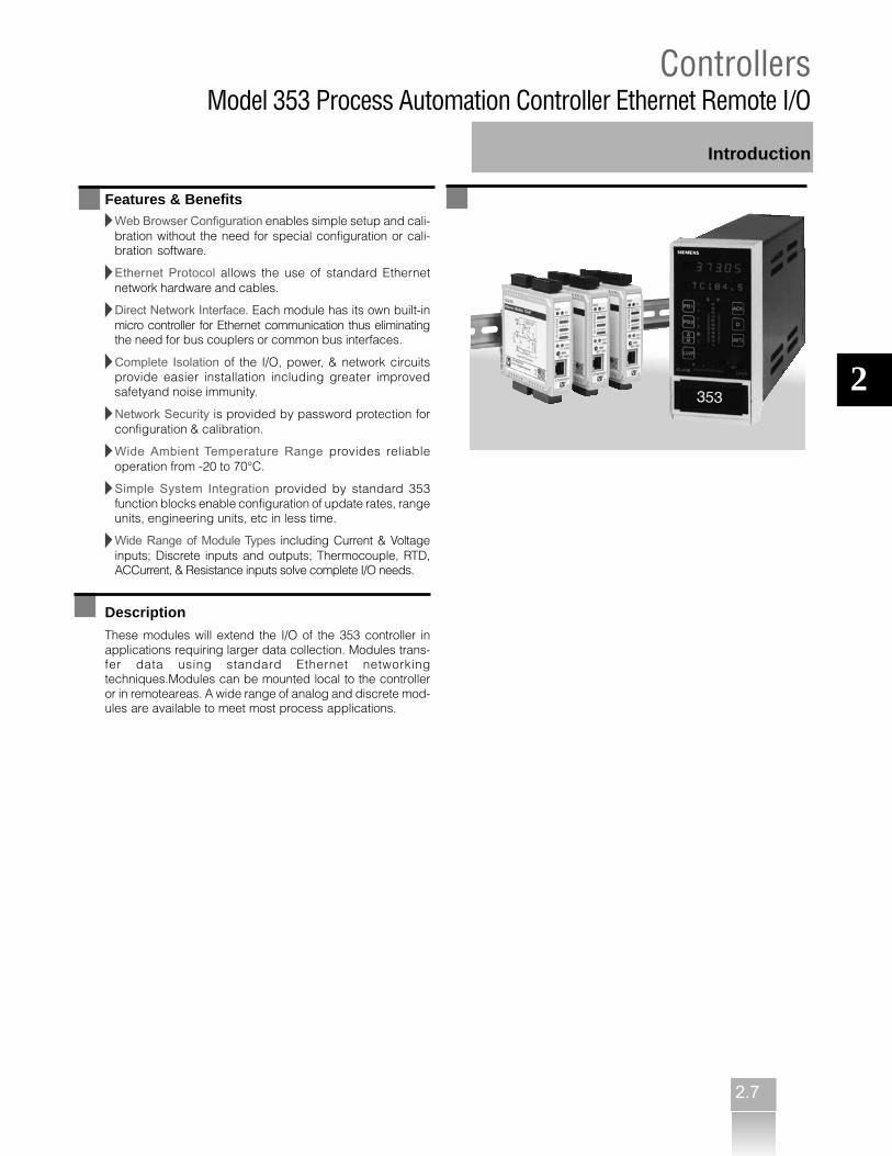
ControllersModel 353 Process Automation Controller Ethernet Remote I/O
Introduction
Features & BenefitsWeb Browser Configuration enables simple setup and cali-bration without the need for special configuration or cali-bration software.
Ethernet Protocol allows the use of standard Ethernetnetwork hardware and cables.
Direct Network Interface. Each module has its own built-inmicro controller for Ethernet communication thus eliminatingthe need for bus couplers or common bus interfaces.
Complete Isolation of the I/O, power, & network circuitsprovide easier installation including greater improvedsafetyand noise immunity.
Network Security is provided by password protection forconfiguration & calibration.
Wide Ambient Temperature Range provides reliableoperation from -20 to 70°C.
Simple System Integration provided by standard 353function blocks enable configuration of update rates, rangeunits, engineering units, etc in less time.
Wide Range of Module Types including Current & Voltageinputs; Discrete inputs and outputs; Thermocouple, RTD,ACCurrent, & Resistance inputs solve complete I/O needs.
Description
These modules will extend the I/O of the 353 controller inapplications requiring larger data collection. Modules trans-fer data using standard Ethernet networkingtechniques.Modules can be mounted local to the controlleror in remoteareas. A wide range of analog and discrete mod-ules are available to meet most process applications.

Ordering data
2.8
2
ControllersModel 353 process Automation Controller Ethernet Remote I/O
Model Number
Remote I/O
Ethernet I/O Modules• DC Current Input - 6 Differential Channels [961EN-4006]• DC Voltage Input - 6 Differential Channels [962EN-4006]• DC Current Input - 12 Single Ended Channels [963EN-4012]• DC Voltage Input - 12 Single Ended Channels [964EN-4012]• Thermocouple/MV Input - 4 Channels [965EN-4004]• Thermocouple/MV Input - 6 Channels [965EN-4006]• RTD/Resistance Input - 4 Channels [966EN-4004]• RTD/Resistance Input - 6 Channels [966EN-4006]• DC Current Output - 4 Channels [972EN-4004]• DC Current Output - 6 Channels [972EN-4006]• DC Voltage Output - 4 Channels [973EN-4004]• DC Voltage Output - 6 Channels [973EN-4006]• Discrete Input - 12 Channels [981EN-4012]• Discrete Output - 12 Channels [982EN-4012]• Discrete Input/Output - 12 Channels [983EN-4012]
Ethernet I/O Module Accessories• Ethernet Switch - 5 Port [900EN-5005]• AC Current Sensor [5020-350]• Ethernet Cat5 Cable - 3 ft. [5035-355]• Ethernet Cat5 Cross-Over Cable - 5 ft. [[5035-360]• Universal Power Supply - 24Vdc/600mA [PS5R-B24]• Universal Power Supply - 24Vdc/2.1A [PS5R-D24]• Universal Power Supply - 24Vdc/5A [PS5R-F24]• DIN Rail - 3.0 in. long [DIN RAIL 3.0]• DIN Rail - 16.7 in. long [DIN RAIL 16.7]• Rack Mount Kit - 19 in. [20RM-16-DIN]• User Manuals on CD [5035-547]
Order No.
▲ ▲ ▲ ▲ ▲ ▲ ▲ ▲
3 0 0 0 1 7 5 03 0 0 0 1 7 5 13 0 0 0 1 7 5 23 0 0 0 1 7 5 33 0 0 0 1 7 5 43 0 0 0 1 7 5 53 0 0 0 1 8 2 23 0 0 0 1 8 2 33 0 0 0 1 8 2 43 0 0 0 1 8 2 73 0 0 0 1 8 2 93 0 0 0 1 8 3 13 0 0 0 1 8 3 23 0 0 0 1 8 3 33 0 0 0 1 8 3 5
3 0 0 0 1 9 6 43 0 0 0 1 9 6 53 0 0 0 1 9 6 63 0 0 0 1 9 6 73 0 0 0 1 9 6 93 0 0 0 1 9 7 03 0 0 0 1 9 5 53 0 0 0 1 9 5 63 0 0 0 1 9 5 73 0 0 0 1 9 5 83 0 0 0 1 9 5 9
■■■■■■■■A6X:

2.9
2
Controllersi|ware OPC Server
Introduction
Features & BenefitsUniversal location for all process information so you onlyhave to enter information once, which significantlyminimizes manual errors
The OPC data server automatically reads the network,identifies attached controllers, and generates a globalsystem database within a few minutes
i|ware OPC data server can be used with any OPC clientto facilitate plantwide communications
Ability to test communication with the controller prior togenerating an HMI interface
Support of other protocols, such as Moore’s LocalInstrument Link (LIL), Modbus, and Ethernet, to integratewith your other control systems and field devices
Monitoring mode that allows on-line value viewingand checking
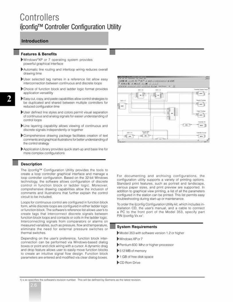
Descriptioni|ware server is an OPC-compliant data server that generatesa system-wide global database with the click of a mouse. i|wareOPC server acts as the universal location for all of yourprocess information, including tags, alarms and history.So, you only ever have to enter information once, whichsignificantly minimizes the possibility of manual errors and cutsyour configuration time in half.
The OPC data server automatically reads the network to seewhat controllers are attached and generates a global systemdatabase. This database maintains itself and updates liveprocess variables, plus changes to the controllers, such astag and range values. Your system database and HMI—complete with status screens, group displays, and control andsequencer faceplates—are automatically created from yourcontrol strategy data.
Because it is an OPC-compliant server, the i|ware OPC serverintegrates with the HMI and any other OPC-compliantclients to facilitate plant-wide communication. It also providesa standard mechanism to transfer data from one to the other.Besides decreasing your costs and increasing yourbottom-line, this approach allows you to move to start-upmore quickly.
AlarmLoggerClient
ProcidiaAlarmWorxTM
TrendLoggerClient
ProcidiaTrendWorxTM
HMIClient
Procidiai|ware
i|wareOPC
Server
AlarmDatabase
TrendDatabase
Controller (Configuration)(i|pac)
Reports

2.10
2
Controllersi|ware for 353 Series Controller
Introduction
Features & Benefits
Five levels of screens are automatically created, based oncontroller strategy, eliminating days of HMI development time
50 ms dynamic animation updates provide operators withup-to-the-minute information
Powerful display creation and animation tools, coupled withan advanced symbol library, expedite operator interfacecustomization
Built-in expressions and calculations, as well as display,trending, and alarm management functions, delivercomprehensive operator information
Scalable and fixed scale displays that allow information tobe displayed in the form and manner required for aparticular application
Embedding of ActiveX® controls and OLE objects todisplay information from other systems and devices
Ability to log, time-stamp, and store controller alarms andevents on a PC hard drive for later review and analysis
Description
i|ware is a comprehensive operator interface—includingstatus screens, group displays, control faceplates, and loopdetail and tuning screens—that is automatically created fromthe controller database. That makes your job easier andsignificantly reduces costs by completely eliminating yourinitial HMI development effort. But, you can still addgraphics and modify the screens that i|ware makes for youto customize the overall look and feel.
i|ware enhances the interface between client and serverapplications using a standard mechanism to transfer datafrom one to the other. The standard, OPC, facilitatesplant-wide communication, because it integrates i|ware withany other OPC-compliant software or system. i|ware alsoincludes Ethernet communications that eliminate the needfor integration with fieldbus technology and dramaticallyreduce networking costs.
Enterprise Edition
The Enterprise Edition provides alarm monitoring andhistorical trending. The alarm and trend servers support acomprehensive list of features. ArchiveX viewers permitquick and easy customization of viewer display format.Alarm logging and trend repports are also available.
i|ware supports VBA scripting for custom applications. Loginsercurity is available.
Specifications
Recommended Requirementsi|station operator workstation- or -Plant Workstation- Pentium 2.0 GHz or higher processor- 1 GB RAM- 40 MB of available hard disk space forapplications- 1 GB hard disk space for historical database- CD ROM drive- SVGA 800x600 resolution monitor (256 colors)
or better- Microsoft Windows 95/98 or Windows NT 4.0
service release 6.0, XP Professional- Microsoft DCOM- Microsoft Internet Explorer version 3.02 or higher- Trend WorX32

2.11
2
Controllersi|ware for 353 Series Controller
Ordering data
Model Number
i|ware
iware PC Operator Interface Software Ver. 3.00• BasicV3.00_500pt• EnterpriseV3.00_500pt• EnterpriseV3.00_1500pt• EnterpriseV3.00_unlimited• EnterpriseV3.00_TimeDemo_1yr_500pt• OPCServers_Modbus_EN_LIL
iWare PC Operator Interface Software Ver. 3.00 Upgrades• BasicV3.00_500pt_Basic_500pt• EnterpriseV3.00_500pt_Basic_500pt• EnterpriseV3.00_1500pt_Basic_500pt• EnterpriseV3.00_unlim_Basic_500pt• EnterpriseV3.00_500pt_Enterprise_500pt• EnterpriseV3.00_1500pt_Enterprise_500pt• EnterpriseV3.00_unlim_Enterprise_500pt• EnterpriseV3.00_1500pt_Enterprise_1500pt• EnterpriseV3.00_unlim_Enterprise_1500pt• EnterpriseV3.00_unlim_Enterprise_unlim
■■■■■■■■■■■■■ ▲ ▲ ▲ ▲ ▲ ▲ ▲ ▲ ▲ ▲ ▲ ▲ ▲
I WA R E B 0 5 V 3 0 0I WA R E E 0 5 V 3 0 0I WA R E E 1 5 V 3 0 0I WA R E E U L V 3 0 0I WA R E E T D V 3 0 0I WA R E OP C V 3 0 0
I W U B 0 5 V 3 0 0 B 0 5I WUE 0 5 V 3 0 0 B 0 5I WUE 1 5 V 3 0 0 B 0 5I WUE UL V 3 0 0 B 0 5I WUE 0 5 V 3 0 0 E 0 5I WUE 1 5 V 3 0 0 E 0 5I WUE UL V 3 0 0 E 0 5I WUE 1 5 V 3 0 0 E 1 5I WUE U L V 3 0 0 E 1 5I WUE U L V 3 0 0 E U L
Order No.
TGX:

2.12
2
Controllersi|station for 353 Series Controller
Introduction
Features & Benefits
Proven operator interface prepacked with i|config, i|ware, andi|ware OPC server, reduces system start-up and test time
- 15" color Thin Film Transistor (TFT) 1024 x 768 LCD - Desk-top operation for greater application versatility
Industrial-grade luminance of 200 cd/m2 and backlightlifetime of up to 20,000 hours that afford a long, trouble-free life
Descriptioni|station is an industrial operator workstation with pre-installeduser interface and configuration software, allowing you toconnect to a live process right away. This sleek unit, whichfeatures an analog resistive screen with a guaranteed 30million-touch lifetime, boasts a wide viewing angle for betteroperator observation.
Designed for reliable operation in the harshest of industrialenvironments, i|station is built to NEMA 4/12 and IP65specifications. It also features advanced communicationcapabilities via four serial ports and an onboard Ethernetcontroller. Plus, i|station’s modular design reduces yourmaintenance and upgrade effort to little more than removalof the front panel.
Specifications
i|station WINDOWS XP
GeneralDisplay Type: TFT color LCDSize: (diagonal) 15" (381 mm)Max. resolution: 1024 x 768Max. colors or grayscales: 256 KDot size: 0.012" x 0.012" (0.297 x 0.297 mm)Luminance: 200 cd/m2Viewing angle: 100°Temperature: 32 to 122°F (0 to 50°C)VR controls: BrightnessSimultaneous mode: YesLCD MTBF: 50,000 hoursBacklight MTBF: 20,000 hoursCPU: Intel® Pentium 2.4 GHzDimensions:16.54" x 12.72" x 4.17" (420 x 323 x 106 mm)
Weight: 14.3 lbs. (6.5 kg)Front panel protection: IP65/NEMA4-compliantHDD:IDE HDD interface [2.5" (63.5 mm) HDD bay]
Memory: 1 GB
Network (LAN): Novell NE2000 compatible,100/01Base-T interface
I/O ports:- 4 serial ports: 3 RS-232, 1 RS-232/422/485- 1 parallel port- PCMCIA Type II x 2, Type III x 1- 1 PS/2 mouse and keyboard interface- Mic-in, Line-in, Line-out, and game port- 2 USB ports
Bus expansion:One expansion slot for half-size PCI/ISA card
Power SupplyOutput rating: 80 W (max.) AC 85 to 264 V inletInput voltage: 115 to 230 Vac at 47 to 63 HzOutput voltage: +5 V at 12 A, +12 V at 1 AMTBF: 50,000 hrsSafety: Meets UL, CSA, CE
EnvironmentalOperating temperature: 32 to 122°F (0 to 50°C)Relative humidity:10 to 95% at 104°F (40°C), non-condensing
Shock: 10 G peak acceleration (11 msec. duration)EMI: Meets FCC/CE Class A
TouchscreenType: ResistiveResolution: ContinuousLight transmission: 75%Controller: RS-232 interfacePower consumption: +5 V at 200 mALifetime: 30 million touches
Accessories- Table top stand - Keyboard & mouse- DB9F/MJ11 cable adapter- MJ11 cable assembly

2.13
2
Controllersi|station for 353 Series Controller
Description
Mounting Dimensions
16.5 (420)
12.7(323.3)
4.2(106)
11.6(294.5)
0.44(11.1)
15.3 (391)
11.7(296)
15.4 (392)
Dimensions are ininches (millimeters).
Cutout for mounting.
2.14
2
Controllersi|station i|station for 353 Series Controller
Ordering data
Model Number
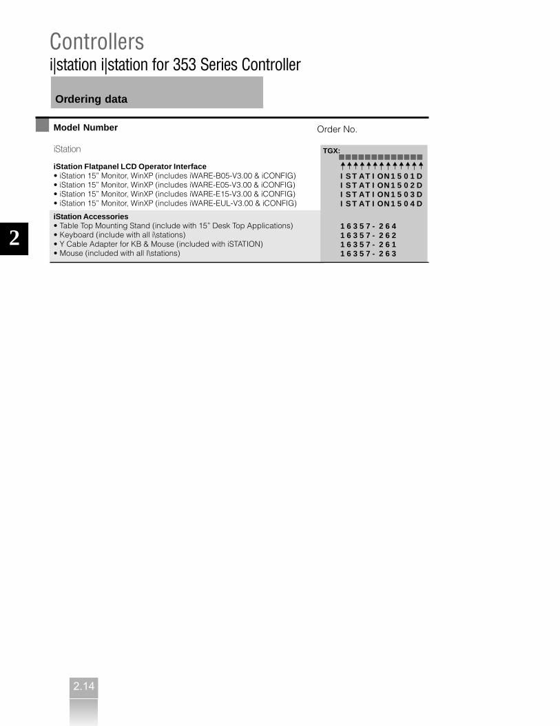
iStation
iStation Flatpanel LCD Operator Interface• iStation 15” Monitor, WinXP (includes iWARE-B05-V3.00 & iCONFIG)• iStation 15” Monitor, WinXP (includes iWARE-E05-V3.00 & iCONFIG)• iStation 15” Monitor, WinXP (includes iWARE-E15-V3.00 & iCONFIG)• iStation 15” Monitor, WinXP (includes iWARE-EUL-V3.00 & iCONFIG)
iStation Accessories• Table Top Mounting Stand (include with 15” Desk Top Applications)• Keyboard (include with all i\stations)• Y Cable Adapter for KB & Mouse (included with iSTATION)• Mouse (included with all I\stations)
Order No.
■■■■■■■■■■■■■ ▲ ▲ ▲ ▲ ▲ ▲ ▲ ▲ ▲ ▲ ▲ ▲ ▲
I S T A T I ON 1 5 0 1 DI S T A T I ON 1 5 0 2 DI S T A T I ON 1 5 0 3 DI S T A T I ON 1 5 0 4 D
1 6 3 5 7 - 2 6 41 6 3 5 7 - 2 6 21 6 3 5 7 - 2 6 11 6 3 5 7 - 2 6 3
TGX:

3.1
3
Valve PositionersSeries 760P/E Valve Positioners
Introduction
Features & BenefitsUniversal design and choice of interchangeable NAMUR IEC534-6 rectilinear VDI/VDE 3845 rotary mountingsprovide wide application flexibility
Double-acting or single-acting service and split rangingafford application versatility in a single unit
Non-interaction of the zero and span adjustments andCAMLOC (TM) cam locking mechanism significantly reducecalibration and setup time
Modular design reduces inventory because it allowsinterchangeable spare parts
Comes standard with 3 cams, linear, quick opening andequal % for application versatility
Description
The Series 760 Valve Positioners provide a cost effectiveuniversal approach to your valve control. Their modularconcept allows all models to be built on the base pneumaticunit (Model 760P). The electro-pneumatic model (Model 760E)is created by adding an I/P transducer to the basepneumatic unit, and a wide range of accessories easily in-stalls inside the unit.
The 760 base pneumatic unit provides cam characterization,split ranging, direct or reverse action, and single or doubleacting without requiring additional parts. Key design featuresinclude non-interaction of the zero and span adjustments.
Series 760 Valve Positioners include provisions for internallimit switch mounting and position feedback devices withoutrequiring additional housings. Thus, the need to stackhousings that impede access to the main enclosureare eliminated.
A spool valve is used to load the actuator for positioning inresponse to an input signal. A characterized cam providesmechanical feedback. There are linear, equal percentage andquick opening operation cam profiles, and a blank profile camis available for custom applications. Rectilinear action lengthcan range from 1/2 inch to 6 inches.
The feedback shaft and characterized cam can be replacedin the field to configure the positioner for use with either arectilinear or rotary actuator. No additional parts are necessaryto change between single or double acting actuators or director reverse action.

Valve PositionersSeries 760P/E Valve Positioners
Technical data
3.2
Mounting Dimensions
3
Valve PositionersSeries 760P/E Valve Positioners
Technical data
3
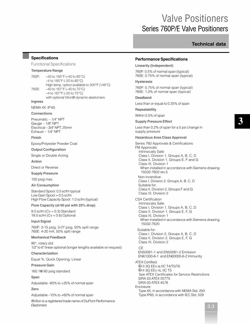
Specifications
Functional Specifications
Temperature Range
760P: –40 to 185°F (–40 to 85°C)–4 to 185°F (–20 to 85°C)High temp. option available to 300°F (148°C)
760E: –40 to 167°F (–40 to 75°C)–4 to 167°F (–20 to 75°C)with optional Viton® dynamic elastomers
Ingress
NEMA 4X, IP 65
Connections
Pneumatic – 1/4" NPTGauge – 1/8" NPTElectrical – 3/4" NPT, 25mmExhaust – 1/4" NPT
Finish
Epoxy/Polyester Powder Coat
Output Configuration
Single or Double Acting
Action
Direct or Reverse
Supply Pressure
150 psig max.
Air Consumption
Standard Spool: 0.5 scfm typicalLow Gain Spool = 0.5 scfmHigh Flow Capacity Spool: 1.0 scfm (typical)
Flow Capacity (at 60 psi with 25% drop)
9.0 scfm (Cv = 0.3) Standard18.0 scfm (Cv = 0.6) Optional
Input Signal
760P: 3-15 psig, 3-27 psig, 50% split range760E: 4-20 mA, 50% split range
Mechanical Feedback
90°, rotary std.1/2" to 6" linear optional (longer lengths available on request)
Characterization
Equal %; Quick Opening; Linear
Pressure Gain
160:1@ 60 psig standard
Span
Adjustable –60% to +25% of normal span
Zero
Adjustable –10% to +60% of normal span
®Viton is a registered trade name of DuPont PerformanceElastomers
Performance Specifications
Linearity (Independent)
760P: 0.5% of normal span (typical)760E: 0.75% of normal span (typical)
Hysteresis
760P: 0.75% of normal span (typical)760E: 1.0% of normal span (typical)
Deadband
Less than or equal to 0.25% of span
Repeatability
Within 0.5% of span
Supply Pressure Effect
Less than 0.2% of span for a 5 psi change insupply pressure
Hazardous Area Class Approval
Series 760 Approvals & CertificationsFM Approvals:
Intrinsically Safe:Class I, Division 1, Groups A, B, C, DClass II, Division 1, Groups E, F and GClass III, Division 1
When installed in accordance with Siemens drawing 15032-7602 rev.5 Non-incendive: Class I, Division 2, Groups A, B, C, D Suitable for:
Class II, Division 2, Groups F and GClass III, Division 2
CSA CertificationIntrinsically Safe:Class I, Division 1, Groups A, B, C, DClass II, Division 1, Groups E, F, GClass III, Division 1
When installed in accordance with Siemens drawing 15032-7620
Suitable for:Class I, Division 2, Groups A, B, C, DClass II, Division 2, Groups E, F, GClass III, Division 2
CE EN50081-1 and EN50081-2 Emission EN61000-6-1 and EN60000-6-2 Immunity
ATEX Certified: II 2G EEx ia IIC T4/T5/T6
II 3G EEx nL IIC T5 See ATEX Certificates for Service Restrictions SIRA 03 ATEX 2577X SIRA 03 ATEX 4578Enclosure:
Type 4X, in accordance with NEMA Std. 250Type IP65, in accordance with IEC Std. 529
2
3.3
Valve PositionersSeries 760P/E Valve Positioners
3.4
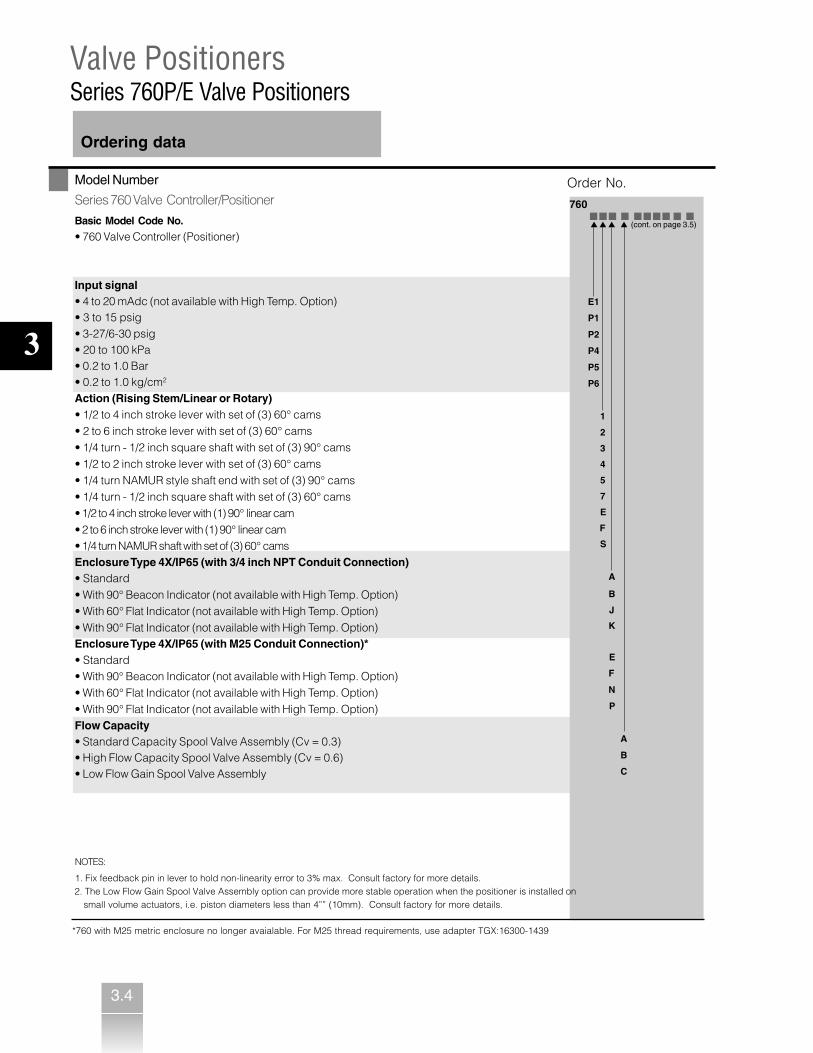
Ordering data
Model Number
Series 760 Valve Controller/Positioner
Basic Model Code No.
• 760 Valve Controller (Positioner)
Input signal• 4 to 20 mAdc (not available with High Temp. Option)• 3 to 15 psig• 3-27/6-30 psig• 20 to 100 kPa• 0.2 to 1.0 Bar• 0.2 to 1.0 kg/cm2
Action (Rising Stem/Linear or Rotary)• 1/2 to 4 inch stroke lever with set of (3) 60° cams• 2 to 6 inch stroke lever with set of (3) 60° cams• 1/4 turn - 1/2 inch square shaft with set of (3) 90° cams• 1/2 to 2 inch stroke lever with set of (3) 60° cams• 1/4 turn NAMUR style shaft end with set of (3) 90° cams• 1/4 turn - 1/2 inch square shaft with set of (3) 60° cams• 1/2 to 4 inch stroke lever with (1) 90° linear cam• 2 to 6 inch stroke lever with (1) 90° linear cam• 1/4 turn NAMUR shaft with set of (3) 60° camsEnclosure Type 4X/IP65 (with 3/4 inch NPT Conduit Connection)• Standard• With 90° Beacon Indicator (not available with High Temp. Option)• With 60° Flat Indicator (not available with High Temp. Option)• With 90° Flat Indicator (not available with High Temp. Option)Enclosure Type 4X/IP65 (with M25 Conduit Connection)*• Standard• With 90° Beacon Indicator (not available with High Temp. Option)• With 60° Flat Indicator (not available with High Temp. Option)• With 90° Flat Indicator (not available with High Temp. Option)Flow Capacity• Standard Capacity Spool Valve Assembly (Cv = 0.3)• High Flow Capacity Spool Valve Assembly (Cv = 0.6)• Low Flow Gain Spool Valve Assembly
Order No.
760 ■■■ ■ ■■■■ ■ ■
▲ ▲ ▲ ▲ (cont. on page 3.5)
E1
P1
P2
P4
P5
P6
1
2
3
4
5
7
E
F
S
A
B
J
K
E
F
N
P
A
B
C
3
NOTES:
1. Fix feedback pin in lever to hold non-linearity error to 3% max. Consult factory for more details. 2. The Low Flow Gain Spool Valve Assembly option can provide more stable operation when the positioner is installed on small volume actuators, i.e. piston diameters less than 4”” (10mm). Consult factory for more details.
*760 with M25 metric enclosure no longer avaialable. For M25 thread requirements, use adapter TGX:16300-1439

Valve PositionersSeries 760P/E Valve Positioners
3.5
Ordering data
Model Number
Series 760 Valve Controller/Positioner (cont’d)
Environmental Construction Options• Standard Temperature (-40°F to +185°F) (-40°C to +85°C)• High Temp. (-20°F to +300°F)(-29°C to +149°C) avail. on 760P w/ no elec. options or approvals• Ozone Resistant with Viton® dynamic elastomers and iso-elastomeric spring
Gauges (Not available with Hi Temp. Environmental Construction “C”• Not Required• Gauges (set of three gauges)Limit Switches (Not avail. with Hi Temp Environmental Construction “C”• Not Required• Mechanical Switches, (2) SPDT• Proximity Switches (2) NAMUR typeFeedback Devices (Not avail. with Hi Temp Environmental Construction “C”)• Not Required• Potentiometer - 1K• 4 to 20 mAdc Feedback• Potentiometer - 1K w/SS feedback gear• 4 to 20 mAdc Feedback w/SS feedback gearDesign Level• RevisionElectrical Approval• None• FM / CSA / ATEX / CE
Series 760 Approvals & Certifications
FM (Factory Mutual) Approvals:• Intrinsically Safe: – Class I, Division 1, Groups A, B, C, D; – Class II, Division 1, Groups E, F, G; – Class III, Division 1;• Non-Incendive: – Class I, Division 2, Groups A, B, C, D• Suitable for: – Class II, Division 2, Groups E, F, G – Class III, Division 2CSA (Canadian Standards Association) Certification• Intrinsically Safe: – Class I, Division 1, Groups A, B, C, D; – Class II, Division 1, Groups E, F, G; – Class III, Division 1;• Suitable for: – Class I, Division 2, Groups A, B, C, D; – Class II, Division 2, Groups E, F, G – Class III, Division 2
Order No.
760 ■■■ ■■■■■ ■ ■ (see page 3.4) ▲ ▲ ▲ ▲ ▲ ▲
A
C
E
N
G
N
1
2
N
1
2
3
4
D
N
6
NOTES:
1. Fix feedback pin in lever to hold non-linearity error to 3% max. Consult factory for more details.
2. The Low Flow Gain Spool Valve Assembly option can provide more stable operation when the positioner is installed on smallvolume actuators, i.e. piston diameters less than 4”(10mm). Consult factory for more details.
3

Valve PositionersSeries 760P/E Valve Positioners
Ordering data
3.6
Order No. 760 Series Valve Controller/Positioner (cont’d) Conversions• Add I/P Module Kit (Converts 760P to 760E) 16300-1355• 3-15 PSI Input Spring (Std. Temp.) 16300-331• (3) Pressure Gauge Kit 16300-442• Add 90° Beacon Indicator Kit (for 1/4 Turn Actuators) 16300-488• Add 60° Flat Indicator Kit (for Lever Action Actuators) 16300-486• Add 90° Flat Indicator Kit (for 1/4 Turn Actuators) 16300-487• 3-15 PSI Conversion Kit (Hi Temp) 16300-640• 3-27/6-30 psi Conversion Kit (Std. Temp) 16300-771• Hi-temps 3/27 PSI 16300-772Options• Add Mechanical Limit Switches Kit (2) SPDT 16300-500• Add Proximity Limit Switches Kit (2) NAMUR type 16300-501• Add 1K Feedback Potentiometer Kit 16300-503• Add 4 to 20 mAdc Feedback Kit 16300-502• Add Mechanical Limit Switches & 1K Feedback Potentiometer Kit 16300-505• Add Mechanical Limit Switches & 4 to 20 mAdc Feedback Kit 16300-504• Add Proximity Limit Switches & 1K Feedback Potentiometer Kit 16300-507• Add Proximity Limit Switches & 4 to 20 mAdc Feedback Kit 16300-506• Add 1K Feedback Potentiometer Kit w/SS feedback gear 16300-580• Add 4 to 20 mAdc Feedback Kit w/SS feedback gear 16300-577• Add Mechanical Limit Switches & 1K Feedback Potentiometer Kit w/SS feedback gear 16300-581• Add Mechanical Limit Switches & 4 to 20 mAdc Feedback Kit w/SS feedback gear 16300-578• Add Proximity Limit Switches & 1K Feedback Potentiometer Kit w/SS feedback gear 16300-582• Add Proximity Limit Switches & 4 to 20 mAdc Feedback Kit w/SS feedback gear 16300-579Note: Above listed options are limited to standard upper temperature limit of +185° F.• Standard Flow Spool Valve Kit 16300-468• High Flow Spool Valve Kit 16300-469• Low Gain Spool Valve Kit 16300-470• Sealing Plate Kit (converts 760E to 760P) 16300-641Cams• 760 P/E Cam Kit, rotary 90° Action (3 cams: Linear, QO, =%) 16300-783• 760 P/E Cam Kit, linear 60° Action (3 cams: Linear, QO, =%) 16300-784• 75° Rectilinear-Linear 16300-805• Cam, 180° - CW, Rotary -Linear 16300-807• Cam, 30° - Rectelinear - Linea 16300-816• Blank Cam Kit 16300-267• Cam, 180° - CCW, Rotary-Linear A6X30005613Spare Parts Kits• Spare Parts Kit includes all recommended rebuild parts as shown in SD760, Issue 7 16300-686Accessories• Manual SD760• User Manual CD (included with each instrument)
3
3.8
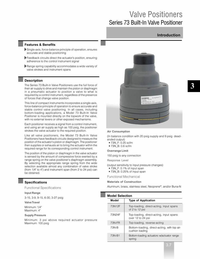
Valve PositionersSeries 73 Built-In Valve Positioner
Technical data
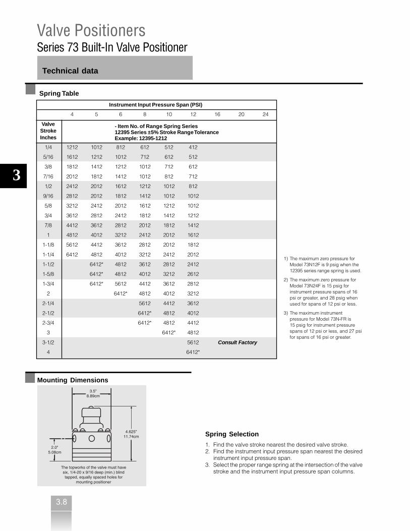
Instrument Input Pressure Span (PSI)
Spring Table
Spring Selection
1. Find the valve stroke nearest the desired valve stroke.2. Find the instrument input pressure span nearest the desired
instrument input pressure span.3. Select the proper range spring at the intersection of the valve
stroke and the instrument input pressure span columns.
Mounting Dimensions
4 5 6 8 10 12 16 20 24
ValveStrokeInches
1/4 1212 1012 812 612 512 412
5/16 1612 1212 1012 712 612 512
3/8 1812 1412 1212 1012 712 612
7/16 2012 1812 1412 1012 812 712
1/2 2412 2012 1612 1212 1012 812
9/16 2812 2012 1812 1412 1012 1012
5/8 3212 2412 2012 1612 1212 1012
3/4 3612 2812 2412 1812 1412 1212
7/8 4412 3612 2812 2012 1812 1412
1 4812 4012 3212 2412 2012 1612
1-1/8 5612 4412 3612 2812 2012 1812
1-1/4 6412 4812 4012 3212 2412 2012
1-1/2 6412* 4812 3612 2812 2412
1-5/8 6412* 4812 4012 3212 2612
1-3/4 6412* 5612 4412 3612 2812
2 6412* 4812 4012 3212
2-1/4 5612 4412 3612
2-1/2 6412* 4812 4012
2-3/4 6412* 4812 4412
3 6412* 4812
3-1/2 5612 Consult Factory
4 6412*
3
- Item No. of Range Spring Series12395 Series ±5% Stroke Range ToleranceExample: 12395-1212
1) The maximum zero pressure forModel 73N12F is 9 psig when the12395 series range spring is used.
2) The maximum zero pressure forModel 73N24F is 15 psig forinstrument pressure spans of 16psi or greater, and 28 psig whenused for spans of 12 psi or less.
3) The maximum instrumentpressure for Model 73N-FR is15 psig for instrument pressurespans of 12 psi or less, and 27 psifor spans of 16 psi or greater.

3.9
Introduction
Valve PositionersSeries 74 Valve Positioners
Features & BenefitsDouble-acting or single-acting service accommodates in-stallation in a variety of environments
Field reversibility reduces downtime and simplifies maintenance
Choice of continuously adjustable standard stroke rangingfrom 1/4" to 48" and continuous span and zero adjustabilitywithin range spring limits provide application versatility
Extra high capacity pilots ensure maximum frequencyresponse and optimum stroking speeds for all actuator sizes
Negative feedback pilot circuit allows the positioner tooperate with a push-pull gain of more than 900:1 (using100 psig supply) with no sacrifice in stability
DescriptionThe Model Series 74 Valve Positioners are universalpositioners that provide versatility, dynamic performance,and high positioning accuracy. They use the piston ordiaphragm in a pneumatic actuator to position a valve towhat is required by a control instrument and hold thatposition, regardless of the presence of forces that changevalve position. As such, supply pressure variations have littleor no effect on the positioner output, which eliminates theneed for a supply pressure regulator.
These valve positioners are two-stage, pilot-operatedinstruments. The pilot circuit activates dual-output boost-ers, which perform opposite actions (when one booster issupplying air, the other is exhausting air.) This “push-pull”action applies to a full differential (supply pressure toatmosphere) across the actuator to drive the valve to theposition required by the control instrument signal.
Model 74 Valve Positioners can also be used for single-acting service on a spring-loaded actuator. In this case, oneof the pilot-booster connections is plugged. See below forrotary-type actuators.
Specifications
Input Ranges
3-15, 3-9, 3-27, 0-15, and 0-30 psig including splitranges within these basic ranges
Valve-Stroke Ranges1
1/4" minimum48" maximum
Supply Pressure
3 psig above full actuator pressure minimum150 psig maximum
Air Consumption
0.2 scfm (inbalanced condition with 20 psig supply)
Overload Protection
150 psig at any connection
Response Level
Output is sensitive to control signal changes as small as0.1% of full range
Ambient Temperature Range
-40 to 180°F (-40 to 82°C)
Materials of Construction
Aluminum, brass, stainless steel, and Buna-N
Rotary Actuators Kit
The Series 74 Rotary Actuator Kits allows for compact instal-lation of a complete assembly (positioner and mounting) tofit inside a 5"x 5"x2-2/3" envelope. The kit’s direct connectedfeedback spring eliminates error-prone connections andlevers, while its spiral feedback spring provides inherentreliability.
Response Level
0.1% F.S.
Linearity
±1.5% F.S.
Input Range
3-9, 9-152, 3-15 psig
Actuator Motion
90° Rotation
1) See next page for additional performance data, design specifications, and a range spring selection chart.2) 9-15 psig range requires a suppression spring.
3

3.10
Model Number
Valve PositionerSensitivityStandard Pilot & Standard Gain• Stabilizing Pilot & Reduced GainGauge Option• With 3 Gauges• Without GaugesIntermediate Sensitivity• Standard Pilot & Reduced Gain (74S only)
Order No.
▲ ▲ ▲
Valve PositionersSeries 74 Valve Positioners
Ordering data
74- ■■■
S
G N
-1
AccessoriesRectilinear Range Spring Kits - Rectilinear range spring kitsinclude a range spring, zero screw, (2) range spring seats,and instructions. All kits include the (2) range spring seats,P/N 12372-384 (not listed below).
Rotary Range Spring Kits - The table below lists the kitnumbers, spring assembly numbers, and their color codes.
Zero Suppression Spring Kits - Zero suppression spring kitsinclude a suppression spring and a spring seat. All kitsinclude the P/N 12372-254 spring seat (not listed below).
Acutator KitStroke and
- Inches - Parts 3-15 3-9 3-27 0-30 0-15
1/4 to 1-1/2 Kit No. 14995-101Spring No. 14996-1Color Code BlackScrew No. 12372-274
1-1/2 to 2-3/4 Kit No. 14995-102Spring No. 14996-2 Consult FactoryColor Code WhiteScrew No. 12372-273
2-3/4 to 4 Kit No. 14995-103Spring No. 14996-3Color Code BlueScrew No. 12372-273
4 to 6 Kit No. 14995-119Spring No. 14996-102Color Code BrownScrew No. 12372-292
6 to 9 Kit No. 14995-117Spring No. 14996-104Color Code GreenScrew No. 12372-292
9 to 12 Kit No. 14995-120 Consult FactorySpring No. 14996-106Color Code RedScrew No. 12372-3034
12 to 19 Kit No. 14995-118Spring No. 14996-110Color Code OrangeScrew No. 12372-303
48 Kit No. 14995-121Spring No. 14996-111Color Code NoneScrew No. 12372-296
N/A
N/A
N/A
N/A
N/A
Instrument Input Pressure Range - psig
Range Spring Kit Table
3
3.11
Valve PositionersSeries 74 Valve Positioners
Technical data
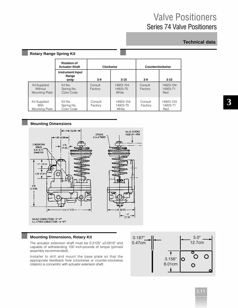
Rotation ofActuator Shaft Clockwise Counterclockwise
Instrument InputRange-psig- 3-9 3-15 3-9 3-15
Kit Supplied Kit No. Consult 14923-154 Consult 14923-104Without Spring No. Factory 14923-70 Factory 14923-71
Mounting Plate Color Code White Red
Kit Supplied Kit No. Consult 14923-154 Consult 14923-103With Spring No. Factory 14923-70 Factory 14923-71
Mounting Plate Color Code White Red
Rotary Range Spring Kit
Mounting Dimensions
Mounting Dimensions, Rotary Kit
The actuator extension shaft must be 0.3125" ±0.0010" andcapable of withstanding 100 inch-pounds of torque (pinnedassembly recommended).
Installer to drill and mount the base plate so that theappropriate feedback hole (clockwise or counter-clockwiserotation) is concentric with actuator extension shaft.
3


3.13
3
TransducersModels 77 and 771 Current-to-Pneumatic Transducers
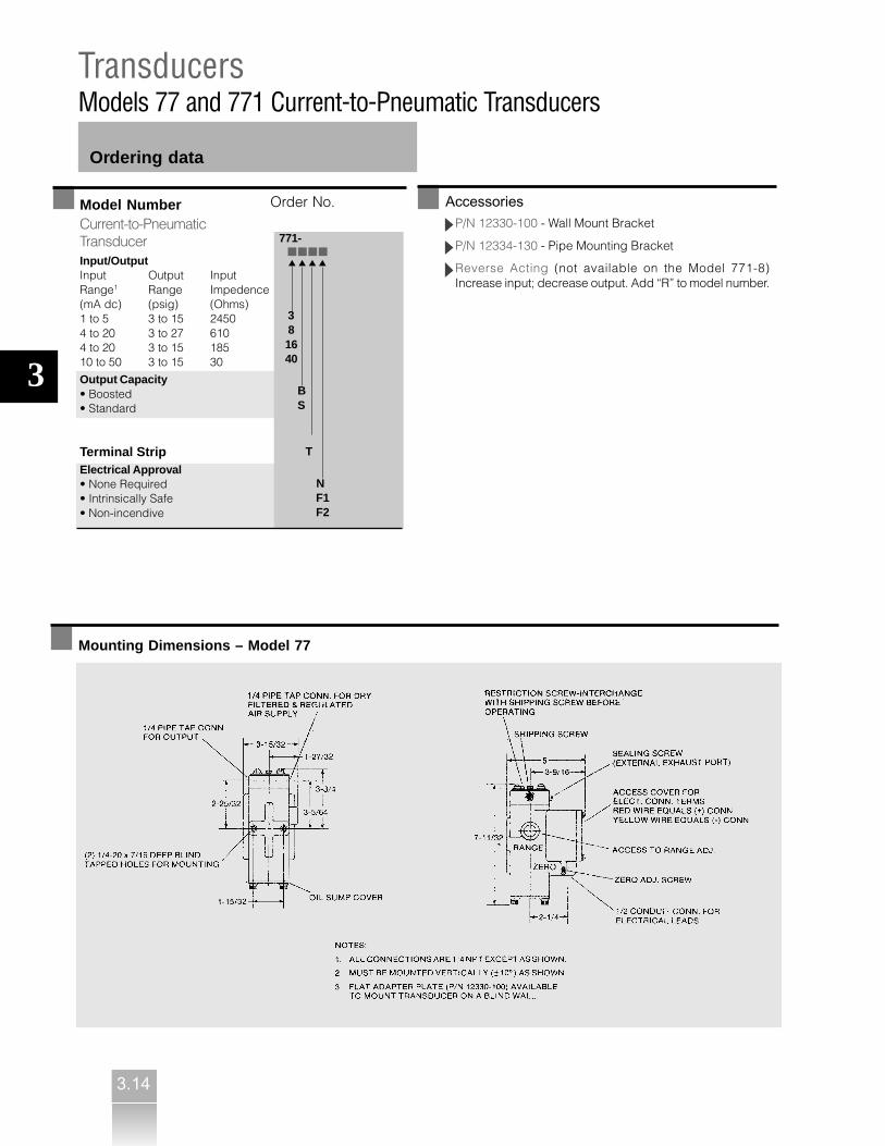
Surface Mounting
Two 1/4 x 20 x 5/16" deep blind tapped holes
Enclosure
NEMA 3RNEMA 4 via conduit vent
Electrical Classification
FM ApprovedModel 77Non-incendive for Class I, Div. 2, Groups A, B, C, D.Dust-ignition proof for Class II, Div. 1, Groups E, F, G.Suitable for Class III, Div. 1 hazardous locations andNEMA 4.
Model 77XXFIntrinsically safe for Class I/II/III, Div. 1, Groups A, B, C,D, E, F, G and NEMA 4 when used with approvedbarriers and converters listed on Siemens drawing#15032-7704/7705.
Performance Specifications
Calibration Accuracy
±0.25% of span
Reproducibility
0.2% of span
Response Level
0.025% of span
Technical data
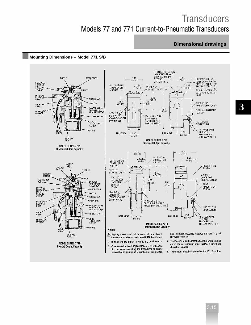
Specifications – Series 771
Functional Specifications
Supply Pressure
20 psig (35 psig for 771-8_ _ _)
Input/Output Data
See Model Selection
Zero Offset Adjustment
+40% and –20% of span
Output Capacity
Standard: 0.16 scfmBoosted: 2.0 scfm
Supply Pressure Effect
Less than 2% of span (change of output for supplychange from 18 to 22 psig)
Temperature Range
-40 to 180°F (-40 to 82°C)
Electrical Connections
Enclosed terminal block, 1/2" threaded
Enclosed
NEMA 3RNEMA 4 via conduit vent
Electrical Classification
FM ApprovedSeries 771_ _ _ F1: Intrinsically safe for Class I/II/III, Div. I,Groups A, B, C, D, E, F, G when used with approved barriersand converters listed on Siemens drawing #15032-7704/7705.
Series 771_ _ _ F2: Non-incendive for Class I, Div. 2,Groups, A, B, C, D. Dust-ignition proof for Class II, Div. 1,Groups E, F and G. Suitable for Class III, Div. 1 hazardouslocations.
Performance Specifications
Calibration Accuracy
±1/2% of span standard unit±1% of span boosted unit
Reproducibility
0.2% of span
Response Level
0.025% of span
Model NumberCurrent-to-PneumaticTransducerExhaust• Atmospheric• Tapped Exhaust
Input/OutputInput Output InputRange1 Range Impedence(mA dc) (psig) (Ohms)1 to 5 3 to 15 24500 to 4 3 to 15 24504 to 20 3 to 27 6104 to 20 3 to 15 18510 to 50 3 to 15 30
Intrinsically-Safe Designation• Intrinsically Safe (omit for otherclassifications)
Accessories• Reverse Acting Output
Order No.
77- ■■■■ - ■ ▲ ▲ ▲ ▲ ▲
1) Other input ranges available; 0 - 3 mA to 0-60 mA, consult factory.
-E
3 3A 8 16 40
F
R
6
3.14
3
TransducersModels 77 and 771 Current-to-Pneumatic Transducers
Ordering data
Model NumberCurrent-to-PneumaticTransducerInput/OutputInput Output InputRange1 Range Impedence(mA dc) (psig) (Ohms)1 to 5 3 to 15 24504 to 20 3 to 27 6104 to 20 3 to 15 18510 to 50 3 to 15 30
Output Capacity• Boosted• Standard Terminal StripElectrical Approval• None Required• Intrinsically Safe• Non-incendive
Order No.
771- ■■■■ ▲ ▲ ▲ ▲
3 81640
B S
T
N F1 F2
AccessoriesP/N 12330-100 - Wall Mount Bracket
P/N 12334-130 - Pipe Mounting Bracket
Reverse Acting (not available on the Model 771-8)Increase input; decrease output. Add “R” to model number.
Mounting Dimensions – Model 77
3.15
3
TransducersModels 77 and 771 Current-to-Pneumatic Transducers
Dimensional drawings
Mounting Dimensions – Model 771 S/B


RegulatorsModels 40, 41, and 42 Precision Pressure Regulators
Technical data
4.2
Air Consumption
See Graph 3
Drift Effect
See Graph 4
Exhaust-Flow Rate (at 25-psig setting)
Pressure rise of 0.25 psig will result from flow of: Model 40: 1.5 scfm Model 41: 2.4 scfm Model 42: 1.7 scfm
Maximum Flow Capacity
See Graph on page 4.4
Standard Mounting
In-line pipe or flush panel up to 1/4" thick (bushing for 3/4"thick panel is optional)Connections: (supply and outlet) Model 40: 1/4" NPT Model 41: 1/8" NPT Model 42: 1/2" NPT
Materials of Construction (materials in contact withregulated media)
Brass, stainless steel, Neoprene, aluminum, and zinc
Accessories
P/N 2932-19 - Mounting Bracket for surface mounting(Model 40 and Model 42)
P/N 10963-73 - Mounting Bracket for surface mounting(Model 41)
P/N 3603-22 - Locknut
Options
Air LoadingProvision for supplementary air loading (100 psig max) inaddition to spring loadingModel 42: 1/4" NPTModel 41: 1/8" NPTModel 40-2: Not availableAdd [A] into the model number.Example: 40A15
Tapped ExhaustProvision for piping exhaust flow away from the regulatorModel 42: 1/8" NPTModel 40 & 41: Not availableAdd [E] into the model number.Example: 42E15
Deletion of Safety release Valve (SRV)The SRV increases exhaust flow capacity when theregulator must exhaust large flows. Deletion of the SRV willimprove drift characteristics (see Graph 4). The SRV is notavailable with the Seimens 41. It is standard with:Model 40: 2, 7, 15, 30, 50 & H50 pressure rangesModel 42: 15, 30, 50, H30, & H50 pressure rangesTo delete the SRV, add an [X] into the model number.Example: 40X15
4

RegulatorsModels 40, 41, and 42 Precision Pressure Regulators
4.3
Technical data
Graph 1 Droop Effect
Test Procedure: Each 30-psig-range regulator was adjusted to 25 psig with 100 psig supply and no flow. Flow was increased tomaximum capacity. All regulated pressure readings were taken at gauge connection in the body of the regulator.
4

RegulatorsModels 40, 41, and 42 Precision Pressure Regulators
4.4
Technical data
Graph 2 Maximum Air Flow, SCFM Delivered
* Supply pressure for other models will bedetermined by multiplying the pressure(s) aboveby the flow values shown below:
Model ValueModel 40H 4.5Model 42 4Model 42H 14
Test Procedure: Regulators were set at 20 psig output with 100 psigair supply. Supply was turned off for one week, after which supply wasturned on at time 0.
The Nullmatic regulator bleeds only the amount of air that passesthrough the pilot nozzle when there is no demand for output flow.The exhaust port starts to close as soon as the flow of regulated airis increased to the output, and it closes completely before the pilot-plunger valve opens. Full pilot flow is then delivered to the output.
Graph 3 Air Consumption Graph 4 Drift Effect
4

RegulatorsModels 40, 41, and 42 Precision Pressure Regulators
4.5
Technical data
Model Selection
Supply Pressure psig
Model Range StandardNo. psig3 Recommended Maximum Modifications
40-21 (1-50"H2O) 5-10 25 X40-7 (6-200"H2O) 50 100 A & X40-15 0.5-15 75 150 A & X40-30 1-30 120 150 A & X40-50 1-50 120 150 H, A & X40-100 1.5-100 150 500 H & A40-200 3-200 250 500 A40-300 7-300 350 500 A40-450 15-450 500 500 A41-15 0.5-15 75 150 A41N152 0.5-15 75 15041-30 1-30 120 150 A41-50 1-50 120 150 A41-100 1.5-100 150 250 A41-2550 25-50 120 15042-15 0.5-15 75 150 A, E & X42-30 1-30 120 150 H, A, E & X42-50 1-50 120 150 H, A, E & X42-100 1.5-100 150 500 H, A & E42-200 3-200 250 500 A & E
Standard ModificationsH - High flow capacity.A - With pressure-tight top housing, containing 1/4" NPT connection for supplementary air loading.E - With 1/8" NPT connection to collect exhaust X - Without safety release.
1) Includes locknut on adjusting stem (optional for all other models).2) For use with Model 65 Square-Root Extractor to maintain minimum 3 psig output.3) At recommended supply pressure.
4


Model 61H is shown


Technical data


4.14
4.15

4.16
4.17

4.20

RelaysModel 661 Amplifying Relays with Bias
4.21
Model Selection
Technical data
Mounting Dimensions
Direct Action
Model No. Gain
661A2 2
661A3 3
661A4 4
661A6 6
Function Equation:
Pout = G (Pin ±K)
Where Pin = input pressurepout = output pressure4

Siemens Industry, Inc.1201 Sumneytown PikePO Box 900Spring House, PA [email protected]
www.usa.siemens.com/pi
Order No.: PIPC-PIPC1-0712All rights reservedPrinted in USA © 2012 Siemens Industry, Inc.
The information provided in this brochure contains merely general descriptions or characteristics of performance which in case of actual use do not always apply as described or which may change as a result of further development of the products. An obligation to provide the respective characteristics shall only exist if expressly agreed in the terms of contract.
All product designations may be trademarks or product names of Siemens AG or supplier companies whose use by third parties for their own purposes could violate the rights of the owners.