process control methods application in training...
TRANSCRIPT

International Journal of Natural and Engineering Sciences 10 (2): 35-42 , 2016ISSN: 1307-1149, E-ISSN: 2146-0086, www.nobel.gen.tr
Process Control Methods Application in Training Set
Kaplan KAPLAN* I. Malik KUNDAKCI Melih KUNCAN Enes TOPRAK Anıl IZGU H. Metin ERTUNCDepartment of Mechatronic Engineering, Kocaeli University, Engineering Faculty, Izmit, Kocaeli, Turkey
*Corresponding Author: Received: July 24, 2016 E-mail:[email protected] Accepted:December 05, 2016
AbstractProcess control has been one of the application topics employed in the industry for years. Nowadays, many experimental setups are designed and produced for educational purposes to make the students be familiar with industrial process systems. In this study, an original process control experimental setup has been designed and constructed for academic uses. Real industrial components such as high performance pumps and materials are used in the experimental setup so that the quality of the system was increased to get a better system. The system was designed to apply various control techniques such as P, PI, PID and fuzzy logic. A developed PLC, Siemens S7-1200, was employed as a controller of the system. The water is used as a fluid to realize control algorithms. Therefore, the basic process control parameters such as liquid level, flow rate, temperature and pressure in the tank can be controlled at this process experimental setup. The main purpose of the system is to use a higher capacity products and give a good education to the students. Keywords: Process control, PID, PI, Proportional, Educational Setup
INTRODUCTIONProcess control have become one of the developing
area used in the industry for many years. Process control efficiency depends on the training of users and engineering students. Giving insufficient training can lead to loss of life and property or great dangers. Giving a good education and ensure better controls is also important. There are many methods in industrial process control systems. Several controls methods applied in process control systems and new control methods are developed to improve success rate of control system [1, 2, 3].
Nowadays, a lot of experimental setups are produced for the preparation of students for industrial process systems. When considered the produced and designed experimental setup used in industry, it is seemed realizing the process systems for same function with low capacity and poor quality product. Therefore, given education has not prepared students for industry.
In this study, the system design process was performed by choosing the products used in industry as same as possible. So, it is aimed to increase the adequacy of the necessary training. Every process control system has a controller. This controller can be microprocessor, microcontroller or programmable logic controller (PLC). Until today, the temperature, level and flow control with PLC have been used for many studies in the literature [4]. While process control experimental setup is being designed, price-performance is taken into consideration. In this way, it aimed to increase quality of the results. In addition, various control methods have been applied to show the students the difference between the methods.
The control in this process control experimental setup is carried out by the information received from the sensors with the aid of the PLC in real time momentarily.
The algorithm was established by the step method on the PLC. Sensor output are compared with predetermined values in interface by the algorithm. After changing the proportional valve opening ratio by PI and PID controls except On/Off control, the valves triggered by this value.
METHODOLOGYProportional Valve ControlProportional valve is activated by solenoid coils and it
can provide flow or pressure continuously or periodically according to electrical inputs. Proportional valve designing
started about 30 years ago and has been an important development so far [5, 6]. Hydraulic proportional valves have been used in a wide range with high-precision positioning system [7]. In this study, the tank level control is performed by the proportional valve flow.
Proportional-Integral-Derivative (PID) ControlPID control method is created using a combination of
proportional, integral and differential factors. Closed-loop control is the most commonly used in the industry since its faster and stable control on the system. [8, 9]. PID is sometimes inadequate application. Therefore, PID control with fuzzy logic algorithm is also the most widely used as controller [10, 11].
In this study, the level, flow, temperature and pressure of fluid in tanks controlled with using PID control method.
Proportional-Integral (PI) ControlThis control method is created by combination of
proportional and integral control method. Although PID control method is the optimization, it cannot apply to all systems. PID control is especially in the fluid control system is inefficient than the PI control because of the differential factor. The control system is complicated due to the inclusion of the differential method because controlled variable is very turbulent and moving instantly. Therefore, PI control is generally preferred on fluid systems. Also, when the PI control is inadequate, it could use with the fuzzy logic method combination [12, 13, 14].
Experimental Setup of Fluid Process SystemNowadays, there are many industrial applications based
on fluid control. This application requires the realization of the important stages and big costs. Big mistakes can stand variety outcomes in the realization of this application. It is important to obtain information before the system was created for prevent mistakes. In addition, it is necessary to provide education about the system. In this sense, it is understood the importance of experimental setup of fluid process.
Many universities around the world, has a web-based training program for engineering education and technical education. Laboratory experiments is important

K. Kaplan et al/IJNES, 10 (2): 35-42 , 201636
as theoretical knowledge. The experiments applied in the laboratory is important to support the theoretical lectures [15]. Experimental setup of fluid process was developed by the company of Perrytech in Figure 1. The fluid velocity and temperature is provided on a tank in this system.
Figure 1. Perrytech experimental setup of fluid process[16]
Festo Company has developed the experimental setup of process as shown in Figure 2. This system has a supply and control tank. Level, temperature and pressure of the liquid control carried out in control tank [17].
Figure 2. Festo fluid process experimental setup [17]
Experimental setup of fluid process was developed by the company of Bytronic in Figure 3. Flow rate, temperature and level of the liquid is controlled in the tank. Control is provided by a PID method and system is monitored with SCADA system [18].
Figure 3. Bytronic fluid process experimental setup [18]
Control Parameters of Process SystemNowadays, many parameters are observed in industrial
applications and provides control. In produced process systems for training, parameters which is controlled is generally level, pressure, flow rate and temperature.
Fluid level controlThe level of the liquid should be primarily control for
the fluid processing system in industry. Usually liquids are used in process control systems. Controlling the status of the liquid in the vessel is extremely important. Therefore, it is a requirement application in many areas such as the fluid level in the nuclear tank and the water treatment plant, dry industry [19]. Because of the slight fluctuations in the liquid level control is the most common in PID method [20]. In addition, where PID is not enough for the level control, PID is used in combination with fuzzy logic [21]. In the fluid level control, there are studies and applications with neural network structure. [22].
A control tank is often used in the experimental setup in the liquid level control applications as seen in the products of Festo and Bystronic companies. With the aim of realizing closest test as same in some industrial applications, the experimental set with three tanks is used [23].
Fluid Temperature Control Temperature control is a very common application in
industry and daily life [24]. It is used in significant various sectors such as industry, chemistry, petro-chemistry, food, and medication. There are many techniques for requirements and applications since temperature control is very sense and important. In some applications where the temperature is kept at sufficient certain intervals, open-close process which has low cost is used. However, in some applications where temperature level is desired to keep at a certain value, more developed methods such as PID control is used. If this control system is inefficient or works wrongly, this can cause financial damage. In order to prevent these damages, raise the awareness of user’s education gains importance. So that many company produce temperature units to give education [25].
Fluid Flow Rate ControlFlow-rate is the volume of fluid which passes per
unit time. This topic takes a part in industry and in order to control flow-rate there are various methods. Firstly, the flow-rate must be measured by supplementation application such as venturi, nozzle, diaphragm or it can be measured magnetically.
Whole fluid flow-rate can be measured by molar or volumetrically. The difference between volumetrically (1) and molar (2) flow-rate is quantity between kilogram and liter per second.
( ) Q A V cos x= × × (1) m V Aρ= × × (2)
Parameters;Q = volumetrically flow-rate (m3/s)ṁ = molar flow-rate (kg/s)A = surface area (m2)V = velocity (m/s)ρ = density (kg/m3)x = the angel between flow direction and surface area
37K. Kaplan et al/IJNES, 10 (2): 35-42 , 2016
Fluid Pressure ControlPressure is the amount vertical force of each unit area
located on a surface. Similarly, fluids also apply force to the surface with its mass. The pressure of gas (3) depends on number of molecule and temperature directly proportion, also depends volume inversely proportion. In closed-space, pressure of gases is measured by manometers.
P V n R T× = × × (3)
Parameters;P = pressure (Pascal)V = volume (m3)n = moles (mol)R = gas constant (Joule/mol*Kelvin)T = temperature (Kelvin)
The Experimental Setup Process EquipmentIn industry or everywhere, quality of equipment is
directly related with quality of product. So that in order to get stable high quality, product-cost must be analized for true results. Besides, capacity and skills of usage elements is essential to use system in various direction.
PumpsThere are two pumps to fill and drain in the system.
Pumps have diaphragm which are the most common and preferred in positive replacement pumps. In Figure 4, there are pumps which have different capacity and they are fed by 24 volts. The speed of engines is controlled by engine driver units.
Figure 4. Diaphragm pumps and drives
Properties of the pump used (1/2)• Input voltage: 24V/24V• Capacity: 17 lt/dak/12.5 lt/dak• Input current: 5A/8A• Size: 252x105x95mm h/210x105x95 mm h
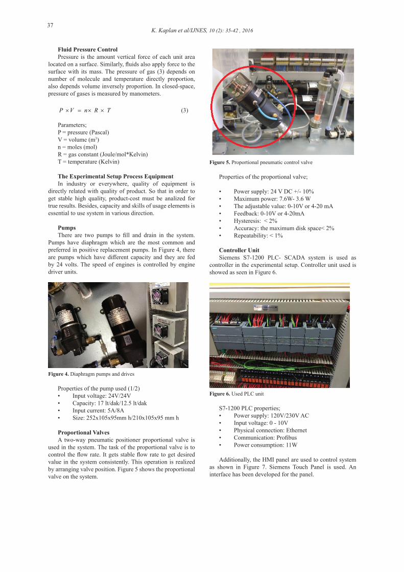
Proportional ValvesA two-way pneumatic positioner proportional valve is
used in the system. The task of the proportional valve is to control the flow rate. It gets stable flow rate to get desired value in the system consistently. This operation is realized by arranging valve position. Figure 5 shows the proportional valve on the system.
Figure 5. Proportional pneumatic control valve
Properties of the proportional valve;
• Power supply: 24 V DC +/- 10%• Maximum power: 7.6W- 3.6 W• The adjustable value: 0-10V or 4-20 mA• Feedback: 0-10V or 4-20mA• Hysteresis: < 2%• Accuracy: the maximum disk space< 2%• Repeatability: < 1%
Controller UnitSiemens S7-1200 PLC- SCADA system is used as
controller in the experimental setup. Controller unit used is showed as seen in Figure 6.
Figure 6. Used PLC unit
S7-1200 PLC properties;• Power supply: 120V/230V AC• Input voltage: 0 - 10V• Physical connection: Ethernet• Communication: Profibus• Power consumption: 11W
Additionally, the HMI panel are used to control system as shown in Figure 7. Siemens Touch Panel is used. An interface has been developed for the panel.

K. Kaplan et al/IJNES, 10 (2): 35-42 , 201638
Figure 7. HMI panel
RESULTS and DISCUSSIONSWhile the system is designing, it is made as versatile.
This allows to implement different control system.Pressure transmitter’s mechanisms have been set under
the tank and it has tried to obtain the desired results by checking the information from these sensors with the aid of the PLC. Control operation diagram is as shown in Figure 8.
Figure 8. Control operation
In the assembly, there are 3 control tank and also 1 feed tank. Level control is carried out in all of these control tank. In addition, temperature control in the second tank and in the third control tank pressure control are carried out. System was implemented without any advanced levels of control methods with using a proportional valve and sensors. In addition, the algorithm developed with PI and PID controls have been implemented to system.
The Level Control with Proportional ValveProportional control is often preferred method especially
in fluid process systems. Although proportional control is not advanced method as PID control, this control method provides controlling mostly successfully. This control is a method that is a combination of fill and drain pump. Level control, using 0-10V or 4-20mA output signals, are realized by changing the opening level of the valve. The valve opening system changes for 1V output voltage to 10% and 4V output voltage to 40%. So the flow rate is achieved instantaneously. In this way, level in the tank is increased and decreased in the amount by changing the opening level
of the valve according to the liquid level. This process is maintained within a specified range.
The algorithm was written for proportional control valve as in the Figure 9. Input is the comparator and button states; the output is the valve opening rate information. Proportional valve and motor drives have been controlled by considering information from the sensors.
Figure 9. The proportional valve control block for Tank 1
The values in the Figure 10 are calculated automatically by TIA portal programmer and the required coefficients are obtained. This value is calculated for each tank and the tank level control is provided. The output was obtained as shown in Figure 11 and Figure 12.
The blue line as shown in Figure 11 is the reference value. The situation in the tank is shown as green line. The red lines are (valve width) output value. Liquid level in the tank can fit the desired value as shown in less than 1 minute. Similarly, as seen in Figure 12, Tank 2 could reach desired value in a short time.
Necessary parameters were calculated for all three tanks. Different parameters for each tank are obtained as shown in Figure 13. These parameters are modified by editing the duplications to implement for the actual system.
Each tank parameters are different so the results are different. Especially in Figure 14, unstable results are obtained because tank 3 level sensor is voltage output.
Figure 10. The proportional valve control parameters for Tank 1
Figure 11. The proportional valve control outputs for Tank 1

39K. Kaplan et al/IJNES, 10 (2): 35-42 , 2016
Figure 12. The proportional valve control outputs for Tank 2
Figure 13. The proportional valve control parameters for Tank 3
Figure 14. The proportional valve control outputs for Tank 3
Level Control with PIDThere are 3 tanks in the control system and these tanks
are connected to the supply tank. This level control is applied for all of the tanks. The level control provides to convert the pressure data which is received by pressure sensors that is bottom of the tank to voltage or current data in real time. Motor speed, solenoid valves, proportional valves are triggered according to the data received form sensors and the PLC control panel is used.
PID control algorithms is developed for each of the tank as shown in Figure 15. The motor speed is changed according to sensor data.
Figure 15. The PID control block for Tank 1
The value can be calculated automatically from PID block for tank 2 and tank 3 as seen in Figure 16 and Figure 19. This makes it possible to calculate approximate values in a short time.
Figure 16. The proportional valve control parameters for Tank 2
PID outs of the tanks can be seen in Figure 17, Figure 18 and Figure 20 sets correctly with a little excess. The highest excess is in the third tank. Because, voltage output sensor is used for tank 3.
Figure 17. PID outputs for Tank 1
Figure 18. PID outputs for Tank 2
Figure19. PID control parameters for Tank 3
Figure 20. PID control outputs for Tank 3
K. Kaplan et al/IJNES, 10 (2): 35-42 , 201640
Temperature Control with PIDThe temperature control settling time is longer other
parameters in both of industrial applications and process control experimental setup. There are 2 heaters and mixer for equilibrium distribution under the tank which is applied temperature control. Heaters are controlled by temperature control relay. After entering the desired temperature and tank temperature, resistances heat the fluid a certain period time. This period is calculated by PID.
The tank temperature boundary conditions are provided by the algorithm that appears in Figure 21. In addition, the control block can be seen in Figure 22.
Figure 21. Temperature algorithm for Tank 2
Figure 22. The PID control block for Tank 2
Figure 23. Temperature control parameters for Tank 2
The coefficients for tank level control is calculated automatically with the data received from sensors by PID block. These values were obtained by optimization, but
by varying the parameters in the system, better results can be obtained. The system has become more stable with the changed parameters as shown in Figure 24.
Figure 24. PID temperature control outputs for Tank 2
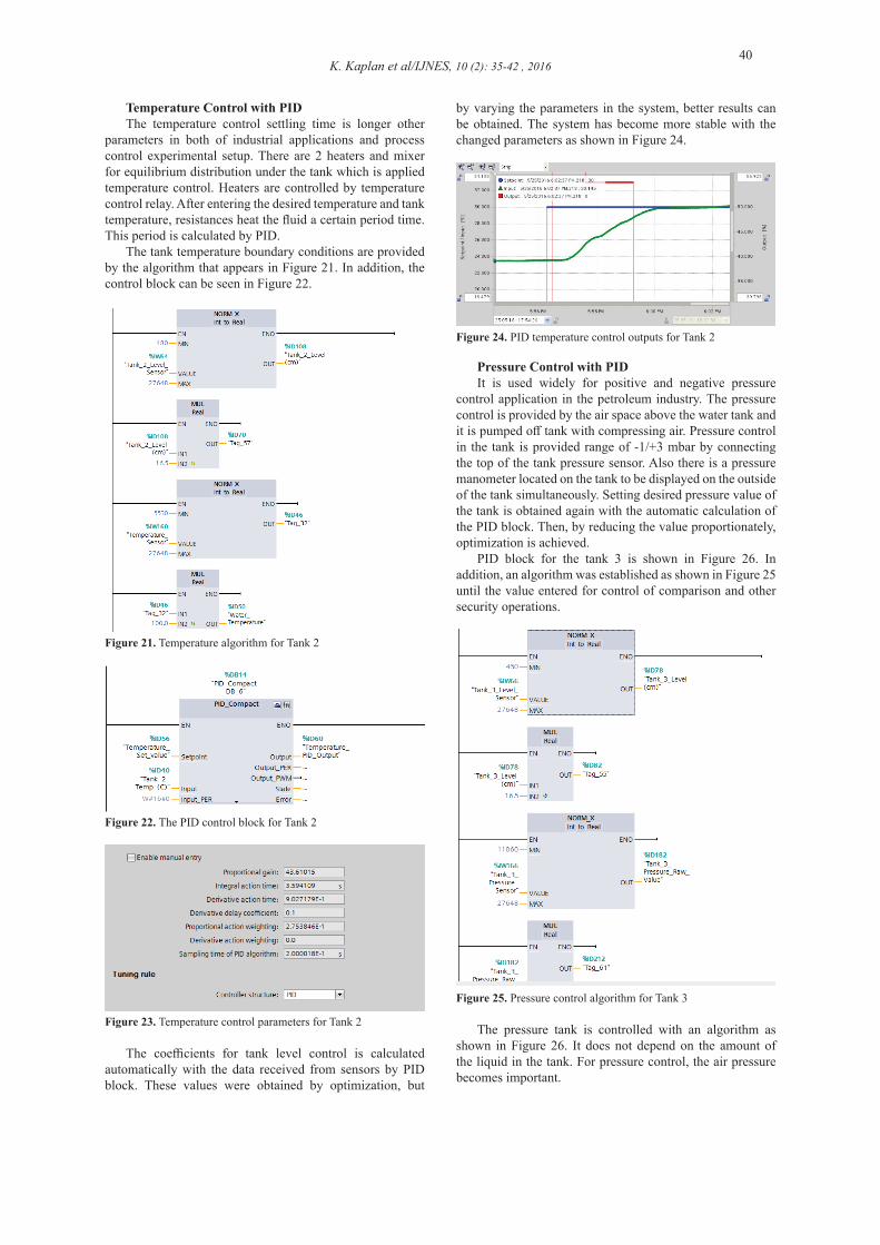
Pressure Control with PIDIt is used widely for positive and negative pressure
control application in the petroleum industry. The pressure control is provided by the air space above the water tank and it is pumped off tank with compressing air. Pressure control in the tank is provided range of -1/+3 mbar by connecting the top of the tank pressure sensor. Also there is a pressure manometer located on the tank to be displayed on the outside of the tank simultaneously. Setting desired pressure value of the tank is obtained again with the automatic calculation of the PID block. Then, by reducing the value proportionately, optimization is achieved.
PID block for the tank 3 is shown in Figure 26. In addition, an algorithm was established as shown in Figure 25 until the value entered for control of comparison and other security operations.
Figure 25. Pressure control algorithm for Tank 3
The pressure tank is controlled with an algorithm as shown in Figure 26. It does not depend on the amount of the liquid in the tank. For pressure control, the air pressure becomes important.

41K. Kaplan et al/IJNES, 10 (2): 35-42 , 2016
Figure 26. PID pressure control block for Tank 3
The most appropriate coefficients are found by the pressure control according to data received from the sensors automatically for increasing and reducing pressure as shown in Figure 27. When pressure control is applied the results are obtained as shown in Figure 28.
Figure 27. Tank 3 PID pressure parameters
Figure 28. PID pressure outputs for Tank 3
Level Control with PIThe system control is provided with proportional and
integral (PI) method. Typically, derivative method is not used in applications where fluid control is used. For turbulent systems this method is constantly because of changing instant error. This method decreases control efficiency. Because this system is turbulent and instant error varies is continuously. Therefore, efficiency is examined by applying PI control. The output values of the control applied tanks is shown in Figure 29, Figure 30 and Figure 31.
Figure 29. PI control outputs for Tank 1
Figure 30. PI control outputs for Tank 2
Figure 31: PI control outputs for Tank 3
CONCLUSIONSIn this paper, the results of tests are presented in process
control experimental setup. Different control methods are compared for control efficiency in the system. According to the experimental results, the PI control method was found to give the best results for this system. In addition, due to the high quality of the proportional valve then PID control, better results observed. PI control, in which the fluid control system is provided that is more efficient than PID method. The fluid in the tank with PI control that creates less turbulence and less delay is triggered. It was observed that ensures longer life. This kind of system is performed in the fluid control, performance monitoring, as well as a better position to form a more stable structure is proposed since this method creates little lapse in PI control method.
Since there is not cooling unit in the system, temperature control takes a long time. The temperature in a shorter time by adding the cooling unit in the following operation can be adjusted to the desired value. Also the fuzzy logic control will be applied in future works.
AcknowledgementThis study was performed in Kocaeli University Sensor
Laboratory. The authors of this paper would like to thank for their contribution to the Sensor Laboratory research and development group.
REFERENCES[1] Gonzalez, Ruben, and Biao Huang. “Control-loop
diagnosis using continuous evidence through kernel density estimation.” Journal of Process Control 24.5 (2014): 640-651.
[2] Yamashita, Yoshiyuki. “An automatic method for detection of valve stiction in process control loops.” Control Engineering Practice 14.5 (2006): 503-510.
[3] Weisheng, Zhong, Zeng Xiaoshu, and Hu Zhaoji. “Research of new experimental system for process control.” Systems and Control in Aerospace and Astronautics,

K. Kaplan et al/IJNES, 10 (2): 35-42 , 201642
2008. ISSCAA 2008. 2nd International Symposium on. IEEE, 2008.
[4] Illes, Cosmina, Gabriel Nicolae Popa, and Ioan Filip. “Water level control system using PLC and wireless sensors.” Computational Cybernetics (ICCC), 2013 IEEE 9th International Conference on. IEEE, 2013.
[5] Yao, Jianjun, et al. “Particle swarm optimization-based neural network control for an electro-hydraulic servo system.” Journal of Vibration and Control 20.9 (2014): 1369-1377.
[6] Milecki, Andrzej, and Dominik Rybarczyk. “Modelling of an Electrohydraulic Proportional Valve with a Synchronous Motor.” Strojniški vestnik-Journal of Mechanical Engineering 61.9 (2015): 517-522.
[7] Ulaş, Hasan Basri, Eşref Çınar, and Musa Bilgin. “Puls Genişliği Modülasyonu İle Hidrolik Oransal Bir Sistemin Sürülmesi.” EJOVOC: Electronic Journal of Vocational Colleges 2.2 (2012).
[8] Samin, Reza Ezuan, Lee Ming Jie, and Mohd Anwar Zawawi. “PID implementation of heating tank in mini automation plant using Programmable Logic Controller (PLC).” Electrical, Control and Computer Engineering (INECCE), 2011 International Conference on. IEEE, 2011.
[9] Cho, Jeong-woo, and Song Chong. “Stabilized max-min flow control using PID and PII 2 controllers.” Global Telecommunications Conference, 2004. GLOBECOM’04. IEEE. Vol. 3. IEEE, 2004.
[10] Hong-yan, Qi, and Xu Jie. “Design of Predictive Fuzzy-PID Controller on Flow Control in Real-Time Multimedia Communication.” Intelligent Computation Technology and Automation, 2009. ICICTA’09. Second International Conference on. Vol. 2. IEEE, 2009.
[11] Weibin, Cao, and Meng Qingjian. “Based on PLC temperature PID-Fuzzy control system design and simulation.” Information Networking and Automation (ICINA), 2010 International Conference on. Vol. 2. IEEE, 2010.
[12] BAĞIŞ, Aytekin, and Yıldız ÖZÇELİK. “Gerçek Kodlu Genetik Algoritma Kullanılarak Sistem Kimliklendirme.”
[13] Bagis, Aytekin. “Fuzzy rule base design using tabu search algorithm for nonlinear system modeling.” ISA transactions 47.1 (2008): 32-44.
[14] Pham, Duc, and Dervis Karaboga. Intelligent optimisation techniques: genetic algorithms, tabu search, simulated annealing and neural networks. Springer Science & Business Media, 2012.
[15] TAŞKIN, Sezai, and Mustafa DEMETGÜL. “Bir Sıvı Dolum Tesisi Deney Setinin Uzaktan Erişimli Kontrolü.” Politeknik Dergisi 12.1 (2009).
[16] https://www.perrytecheducat ional .com/product/multifunct ion-process-control-teaching-system/ (visit date 25.05.2016)
[17] http://www.festo-didactic.com/tr-tr/egitim-siste mleri/yeni-proses-otomasyonu/overview/ (visit date 25.05.2016)
[18] http://www.bytronic.net/product/process-control-trainer-pct-100/ (visit date25.05.2016)
[19] Yongsheng, Qiu, Wang Yong, and Sun Nan. “Design of liquid level control system of nuclear power plant.” Electronic Measurement & Instruments (ICEMI), 2013 IEEE 11th International Conference on. Vol. 2. IEEE, 2013.
[20] Isa, I. S., et al. “Comparative study of PID controlled modes on automatic water level measurement
system.” Signal Processing and its Applications (CSPA), 2011 IEEE 7th International Colloquium on. IEEE, 2011.
[21] Xiao, Qianhua, Deqiong Zou, and Ping Wei. “Fuzzy adaptive PID control tank level.” Multimedia Communications (Mediacom), 2010 International Conference on. IEEE, 2010.
[22] Zhou, Keliang, et al. “Double-tank liquid level control based on genetic algorithm.” Intelligent Human-Machine Systems and Cybernetics (IHMSC), 2012 4th International Conference on. Vol. 2. IEEE, 2012.
[23] Jatoth, Ravi Kumar, Anubhav K. Jain, and T. Phanindra. “Liquid level control of three tank system using hybrid GA-PSO algorithm.” Engineering (NUiCONE), 2013 Nirma University International Conference on. IEEE, 2013.
[24] Jing, Li-Xia, and Cheng Zhao. “A fuzzy auto-tuning PID temperature controller.”IT in Medicine & Education, 2009. ITIME’09. IEEE International Symposium on. Vol. 1. IEEE, 2009.
[25] http://www.feedback-instruments.com/products/education/
[26] process_control/complete_level_process_control_training_system (visit date 25.05.2016)