process and equipment - شرکت weldlxweldlx.com/pdf/standard.pdf · christmas tree studs standard...
TRANSCRIPT

Process and Equipment
ARC Studwelding

Drawn-Arc Stud welding (DS)
Short-Cycle Welding time
< 100 ms
Studs Type PS / US / IS (PT / UT / IT)
Thin sheet metals
Automotive industry
Christmas tree studs
Standard Arc Shielding Gas
D ≤ 16 mm
Studs without Aluminum ball
Industrial application
Studs Type RD / PD / ID / UD
Standard Arc Ceramic Ferrule
D ≤ 25 mm
Concrete anchors Shear conectors
Type SD
Jobside applications
Overhead position (PE)
Horizontal Position (PC)
Steel construction
Refractory Anchoring
systems & Pins
Studs Type RD / PD / ID / UD
ARC Studwelding

Drawn arc Processes
ISO 4063
Welding time t
[ms]
Stud diameter
d [mm]
Current intensity
I [A]
Weld pool protection
Minimum sheet
stud welding with ceramic ferrule or shielding gas
783
> 100 3 to 25 300 to 3,000 CF
1/4 d but not less than 1 mm1)
> 100 3 to 16 300 to 3,000 SG
1/8 d but not less than 1mm
Short-Cycle stud welding
784 < 100 3 to 12 up to 1,500 NP,
SG, (CF)
1/8 d but not less than 0.6mm
Capacitor discharge drawn arc stud welding
785 < 10 3 to 10 up to 3,000
(peak) NP
(SG)
1/10 d but not less than 0.5mm
1) The minimum sheet thickness avoids burn through. Other apllication requirements can call for bigger thickness.
Drawn arc processes (ISO 14555)
ARC Studwelding

- Welding gun - Welding head
- Transformer - Inverter
damping of the piston:
stud diameter > 14 mm
ISO 13918
or Shielding gas tube
for Ceramic Ferrule or Shielding gas
ARC - Process Circuit diagram

ARC with Ceramic Ferrule (CF) ARC - Process
Through-deck stud welding • Stud shear connectors are welded on to load-bearing steel structures through thin, mostly hot-dip galvanized cover sheets (thickness: 1.0 to 1.5 mm). • Economically joining principle - uses the same procedure and technology as drawn
arc stud welding • In combination, the stud shear connectors attached by means of drawn arc stud
welding effect the load transmission of predominantly static shear forces between the concrete and the steel beam and the cover sheets serve as permanent formwork for the applied in-situ concrete.

Studs and Ceramic ferrules (ISO 13918)
ARC Welding elements
Type DD Type RD Type PD
Type UD Type ID Type SD Ceramic ferrule

features: ignition cone angle (~23 °) / CF: ignition cone with aluminum ball
Studs and Ceramic ferrules ARC Welding elements
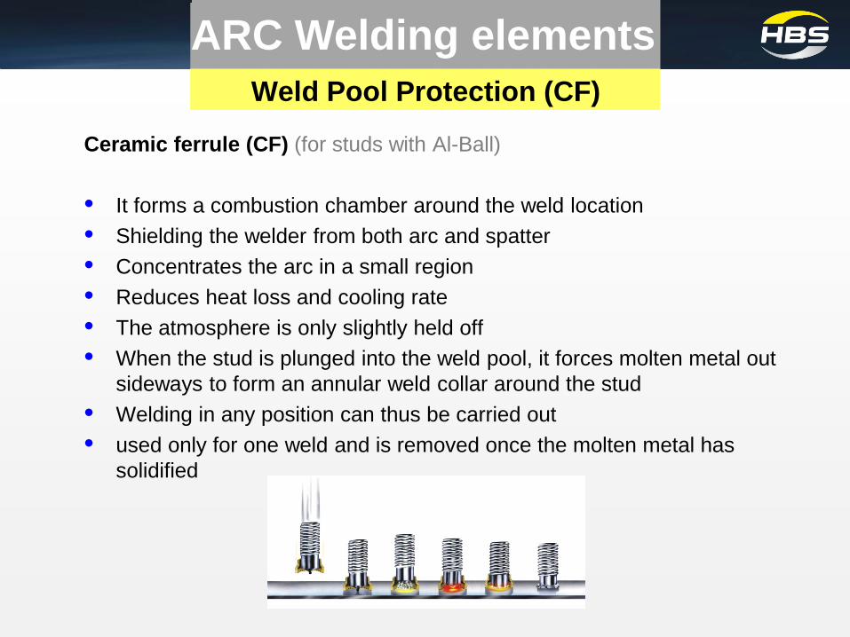
Weld Pool Protection (CF)
Ceramic ferrule (CF) (for studs with Al-Ball) • It forms a combustion chamber around the weld location • Shielding the welder from both arc and spatter • Concentrates the arc in a small region • Reduces heat loss and cooling rate • The atmosphere is only slightly held off • When the stud is plunged into the weld pool, it forces molten metal out
sideways to form an annular weld collar around the stud • Welding in any position can thus be carried out • used only for one weld and is removed once the molten metal has
solidified
ARC Welding elements

Ceramic ferrules for through-deck
ARC Welding elements
Arc ignition at the galvanized sheet metal produces big volumes of vaporized zinc, which is to be removed by degassing holes.
Through-deck ceramic ferrules vs. standard ceramic ferrules • Larger degassing slots to support the degassing • Bigger inside diameter to support the degassing • Larger combustion chamber to be able to accommodate more material (due to longer welding time) • Stronger design of the ceramic ferrule (thermal demands)

Welding parameters ISO 14555 Welding Parameters
Parameters Effect
Welding Current I [A] Size of the melt pool Fluidity of the melt
Welding time t [ms] Penetration Size of the melt pool
Lift L [mm] Geometry of the melt pool Porosity
Protrusion P [mm] Formation of the melt seam Plunging speed Shape of melt seam

Welding parameters ISO 14555 Setup Power unit
Welding Parameters
Welding current [I] A Welding time [t] ms
Dia. < 16mm 80 x D [mm] Dia. < 12mm 20 x D [mm]
Dia. > 16mm 90 x D [mm] Dia. > 12mm 40 x D [mm]
Through-Deck welding 0,8 .. 0,9 (90 x D [mm]) Through-Deck
welding 1.6 .. 1.8 (40 x D[mm])
for normal stud welding of unalloyed steel, Position PA

Lift [L] • Is between (0.8) 1.5 and 8 mm • is proportional to the stud diameter • Coated surfaces: the lift must be greater than it is normally • greater lift increases the arc length and therefore the arc voltage; the
magnetic deflection of the arc also increases (arc blow effect)
Protrusion [P] • Is approximately 1 to 8 mm and proportional to the stud diameter • Depends on: - the desired shape of the weld collar
- the shape of the stud base and - the collar area of the ring (when welding with CF)
Welding Parameters Welding parameters ISO 14555
Setup Power unit

Plunging speed • for studs with a diameter up to 14 mm: approximately 200 mm/s
for studs > 14mm: approximately 100 mm/s so as to prevent the weld pool splashing Polarity • Steel: the stud is connected to the negative pole and the parent
metal is the positive pole • Aluminum: opposite polarity has proven successful for special metals
Arc voltage • values of between 20 V and 40 V • surface impurities such as oil or grease increase the arc voltage
shielding gases reduce the arc voltage
Welding Parameters Welding parameters ISO 14555
Setup Weld Gun

Welding Parameters Welding parameters DVS0903

Welding parameters – Through-deck
Welding Parameters
Reference values of fundamental welding parameters for the through-deck stud welding
SD 19 (1480A / 1.4 s / L 5 mm / P 6 mm) base plate: S355J2G3 (s=12 mm) cover sheet: DX51D + Z275 (s=1 mm) ceramic ferrule for through-deck-stud welding
a) fracture located in the stud when subjected to tensile loading (fracture force: 155 kN), b) radiograph: defect-free welding zone c) transverse section
©SLV München
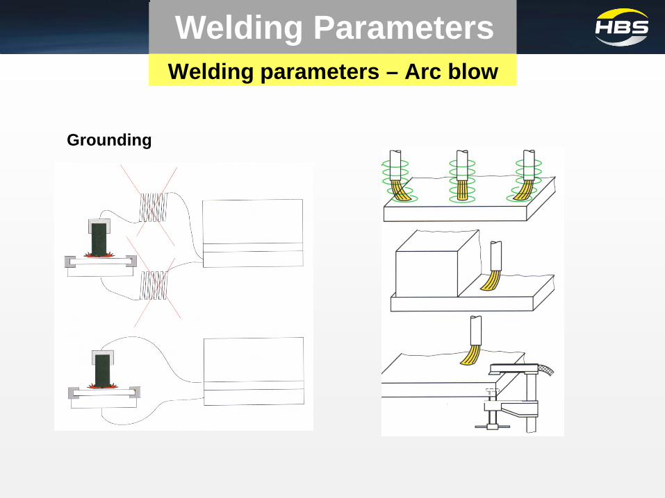
Grounding
Welding parameters – Arc blow
Welding Parameters

“Golden Rule - Cleanliness”
Clean and dry surfaces allow faster welding, higher process stability and better weld quality.
• Studs and ceramic ferrules must be clean and dry • Cleaning before covering the steel beam with the deck sheet • Deck sheet and steel beam must be clean • Deck sheet must be in uniform contact (tight, distance=0) with the steel
beam • Welding area of the steel beam must be clean
be free from dirt, paint, rust, primer, water, oil, mill scale, concrete,… • Removing layers of weldable paint / primer – especially contents of
Zinc - from the weld zone before welding (increasing the weld quality, lowering formation of pores)
• Only weld at dry surfaces (formation of pores, hydrogen cracks) • Welding below 5°C (surface temperature) needs pre-heating
Welding parameters – Sheet metal
Welding Parameters

Techn. Requirements – Power unit
Welding Parameters
• Electronic regulation of welding current
(constant current / no fluctuations even if the power source is heating up ,compensation of long cables)
• Ignition of the arc through a pilot arc with sufficient electrical contact • Clear parameter settings (as security and comfort for the operator) • “hot plunge” of the stud to avoid lack of fusion • Error code display for fast troubleshooting • Possibility of using welding cable diameter up to 120mm ² for larger
distances (max. 80m) between power source and operator • Safety of the power unit according to actual standards (CE, VDE)

Process Requirements
Welding Parameters
Requirement Transformer Inverter Constant current control
Smooth welding current within the working range
Fast current rise without large overshoots High control frequency
Low weight / high mobility
High efficiency
Energy consumption / Power supply
Output at sensitive / unstable power supply (suitable construction site)
Process monitoring
Wide range of parameter setting (eg. step 1A/1ms)
High welding rate / Sufficient ED (eg. at least 4 studs/min. - Diameter at maximum)

HBS EFFICIENT TECHNOLOGY
Future Technology integrated into our compact and mobile Inverter Series Units
Maximum Welding quality
Best welding quality through extremely high stability of the arc, even at weak welding currents or large fluctuations of the mains voltage.
Maximum Welding rate Highest welding rates - increased by 100% compared to standard conventional transformer technology.
Minimum Energy consumption
Minimized energy consumption - energy needed is reduced by 50% compared to standard power units with transformer technology.
Minimum Weight Minimized weight - Inverter technology reduces the weight by 50% compared to power units with transformer technology.
Maximum Degree of efficiency
Maximum degree of efficiency - innovative inverter technology offers best input / output ratio.
Inverter

Inverter Advantage Inverter vs. Transformer
Transformer Power unit Inverter Control frequency
300 Hz Fluctuation in power output • long cables • high temperature
(a.e. high welding rates • Short welding times (t<100ms)
30.000 Hz (full controled and regulated) High precision regulation for constant power output - Full regulation in the arc ignition time (80ms)
Stromanstiegsgeschwindigkeit ca. 250kA/s Stromanstiegsgeschwindigkeit ca. 850kA/s

Inverter – Series Overview IT 2002 / IT 3002
Power Unit: IT 2002 / IT 3002
Welding Gun: A12 A 16 A 22 / A25 Accessory: Grounding Cable, Chuck
Tripod (Shielding gas or Ceramic ferrule)

Application • Suitable for sheet metal thickness: >2 mm • Suitable for concrete anchors in construction sites • Suitable for through-deck welding • Stud diameter (stud range): M3 up to M24 (Dia. 25 mm / 1“) • Higher requirements with process stability and the quality of the weld • Welding in limited quality and tolerance zones
IT 2002 / IT 3002
Process Max. Welding Current
Stud Diameter Weight
Drawn-arc (ARC) Short-Cycle (SC) 400 V, 3 phase 5 to1,500 ms
2.000 A M3 - M24,
Ø 2 - 22 mm
95 kg 209 lbs
2.600 A M3 - M24,
Ø 2 - 25 mm
160 kg 352 lbs
Inverter – Series
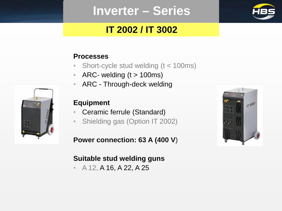
Processes • Short-cycle stud welding (t < 100ms) • ARC- welding (t > 100ms) • ARC - Through-deck welding Equipment • Ceramic ferrule (Standard) • Shielding gas (Option IT 2002)
Power connection: 63 A (400 V)
Suitable stud welding guns • A 12, A 16, A 22, A 25
IT 2002 / IT 3002
Inverter – Series

Power unit Welding power Welding time
Stud diameter Welding rate
(per DVS bulletin 0967)
IT 2002 2.000 A 5 – 1.500 ms
M3 - M24 Ø 2 - 22 mm
Ø 22 – 6 studs/min
IT 3002 2.600 A 5 – 1.500 ms
M3 - M24 Ø 2 - 25 mm
Ø 25 – 6 studs/min
Technical Details Customer Benefit
Welding power IT 2002: 300 – 2000A IT 3002: 300 – 2600A Welding time 5 – 1.500 ms
• Excellent results by working with SC and ARC by
having flexible welding power and welding time • Secure welding of the studs also on critical surfaces like
galvanized and thin sheets • Secure welding of concrete anchors also on critical
surfaces (e.g. through-deck welding) on construction sites
Customer Benefits IT2002/IT3002
Inverter – Series

Equipment Customer Benefit
High Performance and high frequency (30.000Hz) of the inverter allows a dynamic control of the set parameters
• No fluctuation in the power output • No power loss by using longer welding
cables • No power loss at heated power units • Constant power output also by using
shielding gas and ceramic ferrule • Maximum welding quality • Basis for accurate data collection
High arc stability by the inverter technology • Maximum welding quality
Customer Benefit IT - Serie
Inverter – Series

Technical Details Customer Benefits
2 Large wheels 2 Handles Weight: 95 kg
• Most mobile device in its class • Trolley design allows quick transport and high
mobility • Safe for use on construction sites and working
areas • Steps and cables are no longer barriers • No imbalance of the wheels by longer standstill • No punctures and high stability • Handling and weight allow transport in a station
wagon
Lifting eye • Mobile handling and transporting by cranes • Easy transporting
Customer Benefit IT 2002
Inverter – Series

Technical Details Customer Benefit
Through-deck welding • Welding of galvanized sheets by using
concrete anchors • Possible with very stable welding processes
Power connection 63 A (400V) • 125A CEE-connection is not necessary • saving money (can be used everywhere) • High welding rate 6 studs/min.
Robust housing • Especially designed for the use on construction sites
Customer Benefit IT 2002
Inverter – Series

Equipment Customer Benefit
CE-Mark • EU-law: “ free marketable industrial product“
Lifting test • Function control for the gun
IP 23 • Usable on construction sites
Electromagnetical compatibility regarding DIN EN 60974- 10
• Logged quality control • Protection against external influences
High voltage controlled regarding DIN EN 60974- 1
• Logged quality control • Highest protection
Lifting test ARC • To guarantee the functioning of the torch on the welding gun
Error code display • Detection of malfunction
S- Mark • Certificated to weld within increased
electrical risk situations e.g. small rooms and industrial boilers
Customer Benefit IT-Series
Inverter – Series

Arguments
Less weigth / higher mobility / easier transport with 95kg (50%) / 195kg (~70%) less weight
High process stability due to IT Technology, also by using longer cables,
High welding rate (specified in DVS 0967) Dia. 22 - 6 studs/min.
Mains plug: 63A only
Logged high voltage test regarding DIN EN 60974- 1
Protocoled EMC-test regarding DIN EN 60974- 10
High functionality (Before delivering: 500 welding tests and functional test)
Benchmark IT2002 vs. KÖCO
HBS KÖCO KÖCO
IT 2002 ELOTOP 2010 INTOP 2004-1/-2
Schweißbereich
Welding range
M3 – M24
Ø 2 – 22 mm
M3 – RD24
Ø 3 – 22 mm
M3 – M24
Ø 2 – 22 mm
Schweißstrom
Welding Current 300 - 2.000 A 300 - 2.000 A 200 - 2.000 A
Schweißzeit
Welding time 5 – 1.500 ms 20 – 1.500 ms 20 – 1.500 ms
Schweißfolge (Bolzen/ min)
Welding rate (studs / min) 6 (Ø 22) 4 (Ø 22) 4 (Ø 20)
Stromquelle
Power source Inverter
Contr.Trafo / Gleichrichter
Contr.Transformer/Rectifier
Contr.Trafo / Gleichrichter
Contr.Transformer/Rectifier
Maße (L x B x H)
Dimensions (l x h x d) 600 x 500 x 830 mm 805 x 430 x 730 mm 960 x 600 x 830 mm
Gewicht
Weight 95 kg 190 kg 290 kg
Netzstecker (400V)
Mains plug 63 A 125 / 63 A 125 / 63 A
Anschluss
Mains supply 400 V / 3 Phasen 50/60 Hz / 63 AT
400 V / 3 Phasen 50/60 Hz / 80 AT
400 V / 3 Phasen 50/60 Hz / 80 AT
Inverter – Series

Benchmark IT2002 vs. Nelson HBS NELSON NELSON
IT 2002 INTRA 2100 N 4000
Schweißbereich
Welding range
M3 – M24
Ø 2 – 22 mm
M4 – M22
Ø 2 – 22 mm
M6 – M22
Ø 5 – 22 mm
Schweißstrom
Welding Current 300 – 2.000 A 200 -2.100A 300 -2.100A
Schweißzeit / Welding time 5 – 1.500 ms 10 – 1,000 ms 20 – 1,000 ms
Schweißfolge (Bolzen/ min)
Welding rate (studs / min) 6 (Ø 22)
8(M16)
3(Ø 22) 4(Ø 22)
Stromquelle
Power source Inverter
Trafo / Gleichrichter
Transformer/Rectifier
Trafo / Gleichrichter
Transformer/Rectifier
Maße (L x B x H)
Dimensions (l x h x d) 600 x 500 x 830 mm 770 x 520 x 750 mm 850 x 686 x 610 mm
Gewicht
Weight 95 kg 248 kg 330 kg
Netzstecker (400V)
Mains plug 63 A 63 A 63 A
Anschluss
Mains supply
400 V / 3 Phasen
50/60 Hz / 63 AT
400V / 3 Phasen
60Hz/63 AT
400V / 3 Phasen
60Hz/63 AT
Arguments
Less weigth / higher mobility / easier transport with 150kg (60%) / 235kg (~70%) less weight
High process stability due to IT Technology, also by using longer cables
High welding rate (specified in DVS 0967) Dia. 22 - 6 studs/min.
Mains plug: 63A only
Logged high voltage test regarding DIN EN 60974- 1
Protocoled EMC-test regarding DIN EN 60974- 10
High functionality (Before delivering: 500 welding tests and functional test)
Inverter – Series

A 12 A 16 A 22 / A 25 Welding process SC / ARC SC / ARC ARC
Welding range M3 - M12, Ø 3 - 12 mm
Ø 3 - 16 mm A 22: Ø14 - Ø22 mm A 25: Ø14 - Ø25 mm
Application industrial application for welding with shielding gas or with ceramic ferrule
Industry and construction site for welding with shielding gas or with ceramic ferrule
Construction site and through-deck welding „Heavy duty“, for Studs and Concrete anchors till Ø22mm/ Ø25mm
ARC – Weld Guns Weld Guns – technical comparison

Gun Type
Stud Autom. Length
compensation
Adjustments Welding cable
Diameter Length Spring
pressure Max. lift Damping
Length (m)
Diameter (mm²)
Plug (mm²)
Min. (mm)
Max. (mm)
Min. (mm)
Max. (mm)
A 12 2 12 10 150 X (up to 3mm) X 3 mm -- 5,00 35 50
A 16 3 16 10 270 X (up to 6mm) -- 4 mm X 4.85 50 50
A 22 14 22 10 270 X (up to 9mm) -- 6 mm X 4,85 95 95
A 25 14 25 10 270 X (up to 9mm) -- 6 mm X 4,85 120 120
Description: A = ARC – drawn arc Number = maximum stud diameter
Weld Guns – technical comparison
ARC – Weld Guns

Equipment Customer Benefit
Easy handling Easy parameter settings
• Direct visibility of the lift value • Exactly setting by scaling • Flexible setting possibilities • Optimum welding results
Latching setting possibility of the lift and spring value • Unintenional adjustment is not possible
Spirit level • Quick and easy handling for vertical alignment • Ensures stable welding results
Customer Benefit A-Guns
ARC – Weld Guns

Equipment Customer Benefit
Precise length compensation • Constant welding results and high reproducibility
Lightness Compact dimension
• Ergonomic handling • Comfortable and fatigue-free working
Zero-play ball linear bearing for guiding the welding piston
• High plunge speed • Constant moving • Zero-play ball linear bearing • Higher precision then slide bearing
Lightweight bearing • Reproduced setback for constant moving profile and good welding results
Oil plunge damper • For reproduction of good welding results even
with larger stud diameters • No splashing into the melt
Oil lift damper • Constant piston moving profile for stable arc • For reproducing good welds even with big
stud diameters
Customer Benefit A-Guns
ARC – Weld Guns
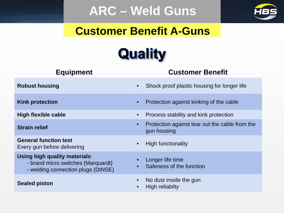
Equipment Customer Benefit
Robust housing • Shock proof plastic housing for longer life
Kink protection • Protection against kinking of the cable
High flexible cable • Process stability and kink protection
Strain relief • Protection against tear out the cable from the gun housing
General function test Every gun before delivering • High functionality
Using high quality materials: - brand micro switches (Marquardt) - welding connection plugs (DINSE)
• Longer life time • Safeness of the function
Sealed piston • No dust inside the gun • High reliabilty
Customer Benefit A-Guns
ARC – Weld Guns

ARC Studwelding Applications Shear Connector

Applications Shear Connector
ARC Studwelding

ARC Studwelding Applications Shear Connector

ARC Studwelding Applications Shear Connector
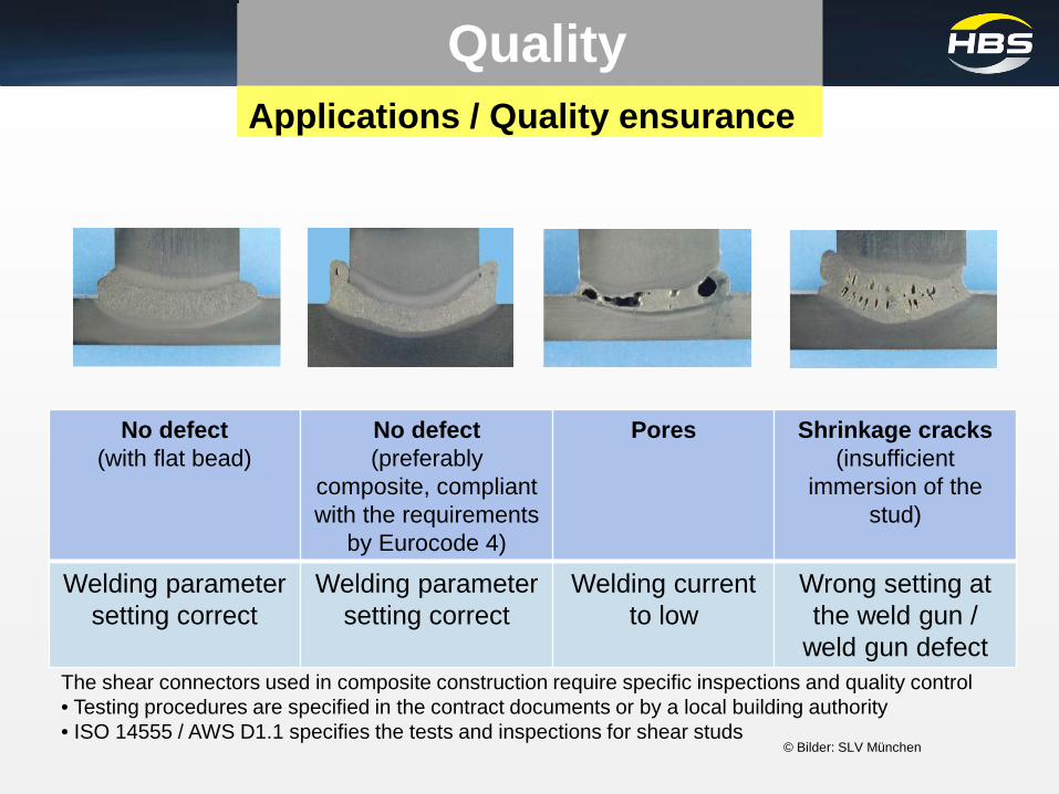
Applications / Quality ensurance
No defect (with flat bead)
No defect (preferably
composite, compliant with the requirements
by Eurocode 4)
Pores Shrinkage cracks (insufficient
immersion of the stud)
Welding parameter setting correct
Welding parameter setting correct
Welding current to low
Wrong setting at the weld gun /
weld gun defect
© Bilder: SLV München
Quality
The shear connectors used in composite construction require specific inspections and quality control • Testing procedures are specified in the contract documents or by a local building authority • ISO 14555 / AWS D1.1 specifies the tests and inspections for shear studs

Weld gun Branch Application Recommended
Power Unit Accessories
A 12 Industry IT 1002, IT 2002
IT 50, IT 90, IT 130
Centering device centering tube
Tripod - ceramic Tripod – Shielding gas
A 16 Industry
Heavy Duty
IT 1002, IT 2002, IT 3002
IT 50, IT 90, IT 130
Tripod - ceramic Tripod – Shielding gas
A 22
Industry
Heavy Duty
IT 2002, IT 3002 IT 90, IT 130
A 25
Tripod - ceramic Tripod – Shielding gas
Application and handling
ARC Studwelding
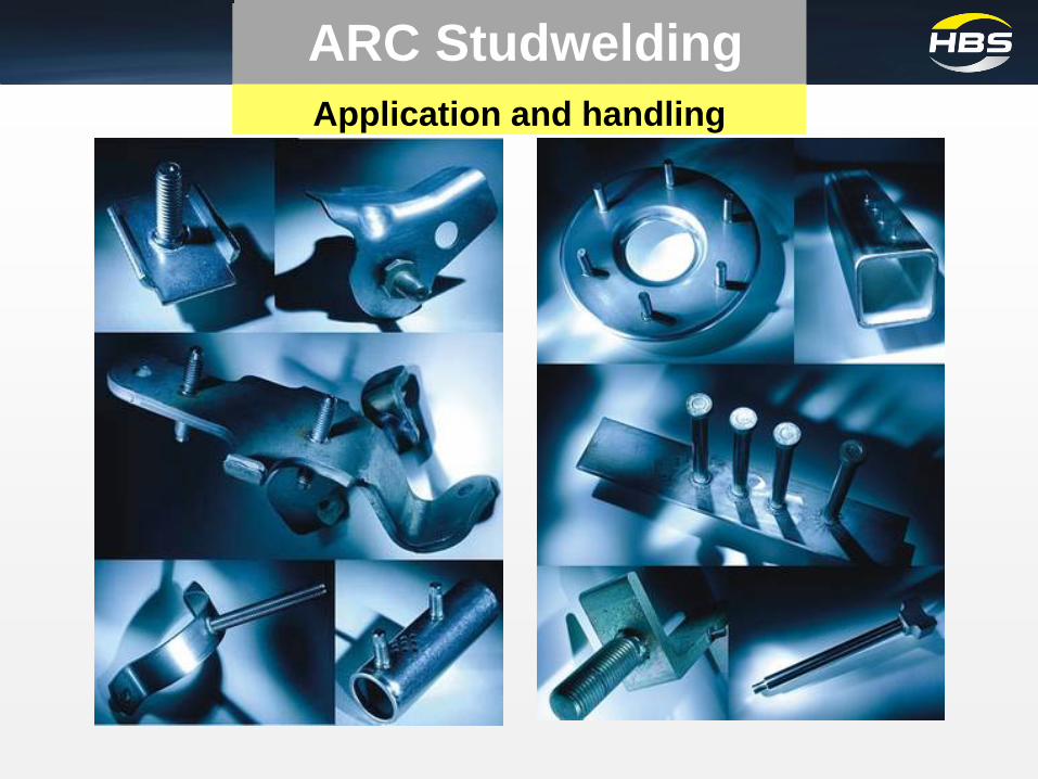
Application and handling
ARC Studwelding