proceedings joint symposium on design and operation of fluid...
TRANSCRIPT
Proceedings
JOINT SYMPOSIUM ON DESIGN AND OPERATION OF FLUID MACHINERY
June 12 - 14, 1978 Colorado State University Fort Collins, Colorado, U.S.A.
VOLUME I
1NlEHNATlOIYAL ASSOCIATIOEi FOR HY DIIAULIC RESEARCH Section for Hydraulic Machinery, Equipment, and Cavifzkm
AMERICAN SOCIETY OF MECHANICAL ENGINEERS Fluids Ehgintoring D i v i s l ~ n
AMERICAN SOCIETY Or" ClVtL ENGINEERS Hydraulics Division
The unsteady, dynamic characterization of hydraulic systems with emphasis on cavitation an? turbomachines.
Ghristopher Brernar~ California Lnstitute of Tecl~nology
Pasadena, California 9 1125
Abstract
The ability to analyze and n l ~ d e l the unateadjr, dy t~a~n ic re- sponse of hyd r~u l i c systems has arisen from the need for opera- tional stability, flexibility and coutrolled transient behv io r . Fol- lowing a general discuseion, this payer discusses experiments and analysis directed toward identification of the dynamic responve of hydraulic pumps, both cavitating and n~n-cavitating. It is shown t h d t rather n-rudesf amounts of cavitation cause the pun~p to becanle dynamically active and therefore capable of oxciting instabilities and re-onance with the hydraulic syytern.
La capstit; poxr a n a l y s ~ r et modeler la rbyonst: dyr.a- rdqua , en ril;innc i r r6gul ier . de syst imes hydraul iq~~cs , provient de la r,t?'ce'ssitd d 'obteni r leur stabilith operationelle, Ieur flexi- 'u~litk et de cor~trular leur comportemant err rggirne Cransitoire . npr&s Lme di~cubsion g&n&rale, deb ex~,r&riences et analyses ef- fectufios en vuc de l'identification t ie la rEponse dynamique de p m - pcs hydrauliques (i l a fois cavitantes r i non cavitantes) sont dis- cutges clarrs cet article. Il e ~ t montr;! qu'une gon~pc p u t deveuir active de f a ~ n n dynamique m&me pour de petites cavitations et es t doac capable d e susciter des inatabilitis et dlen+,rar en risonance avec le systeme hydraulique.
I, Inti-oduction
Thia paper i s concerned with the unsteady, dynamic renponse oi hydrao!ic S Y E ~ M S and, !L partic.ular, with the r61c played by tur- bumaohines in determining the stability or transient response of such internal flow networks. The need for such inf4~rrnatiun has arisen bccsuse of (i) an increasing sensitivity to hydraulic system instabil- ities for reasons of safety, operational stability and flexibility ( i i j r e q ~ i r en~en t s for the analysea of the resporrse of hydraulic sys - tenis to externally imposed transients and (iii) a nced fur analytical models for Ixse in the d c s i ~ n and positioning of corrective hardware.
The basic approach adopted hare it; andogous to that of elcc- t r ic circuit sndysio. Tka pressure, p, ;rnd mass flow rate, ;n, a i every point+ the h~clraulic system are subdivided i n t ~ mean fluw componeikts, p and m, -which a2.e independent of time, t, and fluctuating components, p and rn, for each frequency, n:
< h e r e j i s the imaginary unit. Re d m o t e s the real part, aud F, m are complex in general. A s the above implies, the analysis will be confined to brnall, linear perturbations about the meal1 flow. F u r - thermore, any general trdrwient response will be syuthesized f rom knowledge of the system wespohse for individual frequollcies, a. For thin purpuse, we require the dynamic trsxlsfer function for each element in the hydraulic system. This t ransfer function o r matrix.
1 z], reletea the fluctuating pressure and mas8 flow rate tt

- CI
discharge from_ the element, pa and m,, to those quantities at in - let, r;, and m, ; in hydradic systelns [ z ] is most cn;tvsniently choben to be defined as
Tire transfer matrix, [z], will be a frulction not only of frequeuuy, n, but alao of the mean flow cvnditiuns in the hydraulic element. A few simple examples will help o u r interpretation later of m o r e com- plex transfer fmctionu. The flow of an incomyreseible fluid in a rigid, uniform pipe will have vr~ly one nun-zero matrix element, narncly Z1, ; - Z l a is the irnpeda,~ce of the pipe. A t low frequen- cies i t will be comprised of R -t jQL where K is the frictional re- sistance obtained from the mean flow friction factor aricl L ic the inertzmce due to the acceleration uf the rriass of f l ~ i d in the pipe. At higher frequencies it will boco:ne a cor;lplex function ui freqaency which will reflect the non-trivial behavior of the boundary layers ur~der fluctuating conditions. On the other hand a simplo camplii.nc-e consisting of a volume of gas cornrrmnicatirig pressure-wioa with the flow- in a duct will yield a non-zero valse of of the form -jllC where C is Paown as the compliance. The elect r ical amlogy is a capacilor to grocmd.
There are several general properties of the t ransfer rqatrix, [ z ] , which a r e particularly important to discuss at this point and they iuvulve the value af the determinant, D, of [ % I t [I] where [I] i s the unit matrix:
(a) Any simple dynamic Bystem which is described by L, R an2 C elemunts wil l , by the theoram of reciprocity, have a de te r - rnirrant, D, equal tu cri ty. Note that such a 13cucriptibn implies an infinite wave propapatioil speeci. A11 such systerils are dy:lsmi cally passive.
(b) h so f a r as the author has been able to deterniirre the val- ue of D for any passive systum with a finite wave ropapation speed i s complex in general, but i t s spectral radius, ( D r , is s t i l l equal to unity. This is true, for example for the flow uf a compressinle fluid in a uniform duct (which, in*:identally, has a t ra l~sfer function in which all four e l ~ m c n t s a re nun-zero).
Several c~nclusions can be drawn f rom the above observa- tions. rirst, it is clearly important to cctncentrafe attentkin on those elernects in a kfdraulic s y s t e m which are dyn=lically "activet1 and therefore capable of exciting instabilities and resoaances within the system. Sach elements can therefor? be identified either exper- imentally or analytically 4 s those ir. which the spectral radius si the determinant. D, is @ equal to unity. Pox~lps ~ l l d t u r b j n ~ ~ could clearly be active dynamic elernellts and the remainder of thia paper will concentrate on the clynamic transfer function f o r pumps (Fanelli (1972) was among the first to consider transfer fur~ctions f o r pumps). It is also worth noting that two-phase flows iuvolving phase char~ge also csxhiblt active transfer matrices ( e . g. Prennen (1978a)). Hence particular attention will be paid transfer m a t r i c e s for cavitatiug pumps.

2 . _Dynamic Transfer Functions for Pump?
Though the need for dynamic information on pun~ps extends to many hydraulic systems, i t has beell r n u s t intensively studied in the context of liquid-propelled rockets because of the need f o r anal- ysis of the POGO instability endemic to all such rockets (e. g. Rubin (1966) , Vauge, Fidler and Zehnle (1972). Rocketdyne Report (19671). Most of the early attenlpts to synthesize the dynamics of tha fuel and oxidizer turbopurnps were essentially quasi-static. The pump resistance was obtained from the slope of the steady state head r i s c versus flow r a t e curve at the operating point; to this was added some estimated inertance to obtain the qudsi-static pump impedance. Irx one of the few previous experimental investiga- tions, Anderson, Blade and Stevens (1971) measured the dynamic inlpedance of a non-cavitating centrifugal pump for frequencies up to 50 Hz. Their results depart from the quasi-static values at quite low frequencies, the rewistmce increasing and the inertance de- creasing with frequency.
Ullder cavitating conditions two othcr non-zero elements were generally added; the slope of the steady state head r i s e versus inlet p ressure yielded some value for XI., (the "pressure gain" t e rm) and some estimated volume of cavitation in the pump was used to obtain a "~avitat ion compliancei1, C, for thc pump so that Z,l,f - j2C (see fa r example Rubin (19t~6), Vaage, Fidler and Zehnle (1972)). Later Brenncn and Acosta (1076) pointed olrt that the quasi- static approach applied to the cavitating case would lead not only to a a non-zero Z,, hut also to a value for Z,. . The mean operating state within t.he punlp i s descrjbed by the flow coefficient, cp (=U, /U, where Ub i s the mass average axial velocity of ths flow at inlet and 14 1s the impeller lip speed) and lhe cavitatiot~ nurriber cr = ~ l - p , ) / ~ o ~ ~ where p, i s the vapor pressure and p the liquid density. The head coefficient, 41 (defined at the total p ressure r i ~ c across the pump divided by p u?) is then a function of cp and 3. Also the volume of cavitation is a funct,onxrirnarily of cp and a, Then uuder quasi-static f1uctl:ations (m2-1%) is s in~ply related tuthr rdte of change of this volumc wi th t ime. Brenr1c.n a l ld Acosta (1976) utilized a cavitating cascade model with flzlly developed blade cavi- t ies to evaluate ( i ) the change in voIvmr with inlet p ressure (or 0 ) which leads to a value of the compliance, C .: - j R C ) and (ii) the change in volume with a~lgle of attack (or 0) whiclr leads to a value of the "mass flow gain factor", M (Zaa = -jSM).
The above analysis has two limitations. F i r s t it i s purely quasi-static and departures from this might be expected at fa i r ly low frequencies. Secondly, cavitation in a pimp occurs in a number of fortrls (see, for example, Brennen (1973)); Subbly cavitation i s the most common type and blade cavities, if they occur at all, a r e usu- ally accompanied by considerable bubbly cavitation. Relatively lit- tle analytical research has been done on the dynamics of bubbly o r backflow cavitatior, though in soma preliminary studies (Brennen (1973)) it was ahown that streams of cavitating bubbles do have a n identifiable compressibility or compliance. However, it i s clear that the most valuable information at the present time will come from experimental measurements of the dynamic transfer functions of turbomachines; in the next section we describe the results of such an experiment,
3 . Experimental measurement of pump transfer functions
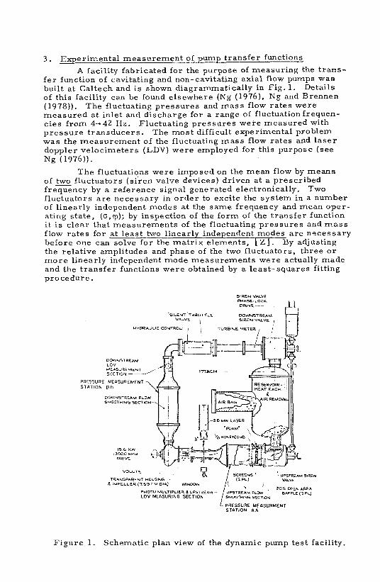
A facility fabricated for the purpose of measuring the t rans- fe r function of cavitating and non-cavitating axial flow pumps was built at Caltech and i s shown diagrammatically in Fig. 1. Details of this facility can be found elsewhere (Ng (1976), Ng and Brennen (1978)). The fluctuating pressures and mass flow rates were measured at inlet and discharge for a range of fluctuation frequen- cies from 4442 Hz. Fluctuating pressures were measured with pressure transducers. The most difficult experimental problem was the measurement of the fluctuating mass flow rates and laser doppler velocimeters (LDV) were employed for this purpose (see Ng (1976)).
The fluctuations were imposed on the mean flow by means of two fluctuators (s iren valve devices) driven at a prescribed frequency by a reference signal generated electronically. Two fluctuators a re necessary in order to excite the system in a number of linearly independent modes at the same frequency and mean oper- ating state, (o, v); by inspection of the form of the transfer function i t i s clear that measurements of the fluctuating pressures and mass flow rates for at least two linearly independent modes are necessary before one can solve for the matr ix elements, \ Z ] . By adjusting the relative amplitudes and phase of the two fluctuators, three o r more linearly independent mode measurements were actually made and the transfer functions were obtained by a least-squares fitting procedure.
SIREN VALVE PHASE-LOCK ORSYE--
'SILENT'THROTTLE VALVE
WWNSTREAM
I UIDRAULIC CONTROL- 1 / TURBlNE METER I '
L PRESSURE MEISVRMENT STATION A A
Figure 1. Schematic plan view of the dynamic pump test facility.

The typical levels of fluctuation in the m s s s flow rate were abuut 2% of the mean mass flow rate; the corresponding pressure fluctuations were a few percent of the mean total pressure r i se across the pump. Tests showed that these levels were small enough to be considered linear perturbations.
Considerable effort was expcnded to ensure the accuracy of the LDV rncasurements of fluctuating flow rate. P r io r to these measurements the flow was smoothed by means of screens and l ~ ~ n e y c o r n h s followed by 9:1 converging nozzles in order to assure uniform velocity profiles at both measuring stations and to reduce the turbulence there to a level of about 1 /2Yo (this is par t icdar ly difficult at discharge and accounts for the large downstream flow smoothing section). A signal to broad-band nuise ratio of about 4:1 was obtained. However, by cross-correlating the returning fluctu- ating signals with the basic reference signal driving the system the effect of the noise was substantially reduced. For details of this, m a n y other ancillary measurements (accelerations, shaft axial motion and fluctuating rotating speed) and the processing of the data s e e X g (1976) and Ng and Brennen (1978).
Though a number of impellers have been tested, we concen- t rate here on the results for a 1/4 scale model of the low-pressure oxidizer pump in the Space Shuttle Main Er~ginc (Impeller IV). The transfer functions for other impellers are qualitatively similar sug- gestingthatthe results aye rather insensitive to the particular ge- ometry (indeed it is expected that centrifugal pumps would have similar transfer functions). The steady state performance of this model is shown in Figs. 2 2nd 3 and compares favorably with the full scale impeller performance (Rocketdyne Division, Rockwell Inkrnatioual, personal communication) obtained later. The rele- vant data in F ig . 2 i s that with the stator.
Figure 2. Non-cavitating performance of Impeller IV with and withont the stator f u r various rotative speeds. Also shown are full-scale test data for this impeller lRvcketdyne Division, North American Rockwell, personal communication) and the theoretical, loss- less perlorrr~ance curve (Brennen (1977)).

lMPELLER IIL STEADY STATE REWLTS 1 9 0 W I -.- FULL SCALE ROCKETDYNE TESTS 0
(COCA IA 7 4 0 - 0 1 5 1 ~ + ~ 0 . 0 6 9 1 WINTS I T WHICH DYNAMIC TRANSFER FUNCTIONS WERE OBTAINED ARE MARKED A . 8 . - . M.
Figure 3 . Measured steady state cavitation performance for Impeller IV at 9000 rpm and various flow coefficients, ep, as indi- cated ( ). Also shown a r e the results of some full scale tests for c p = 0.069 performed by Rocketdyne (COCA 1A 740-15). The points a t which dynamic t ransfer functions were obtained a r e shown by the letters; test A'F were performed at 9000 rpm and cp~0.070; test G'I a t 12,000 rpm and cpm0.070; tests J*M at 9000 rpm and epw0.076.
Transfer functions were obtained over a range of mean operating states at points shown by let ters in Fig. 3 . It is inter- esting to note that the present hydraulic system became unstable without external fluctuation within a range of operating states near breakdown. This auto-oscillation behavior will be the subject of future study (Braisted and Brennen (1978)) but clearly reflects the active nature of the pump dynamics in this range of operation. Only one attempt was made to measure a transfer function in this range (point E).
4. Results
The results a r e presented non-dimensionally by generating a t ransfer function relating non-dimensional pressures and mass flow rates, defined by dividing by $ PU: and pU, A t respectively where A1 i s inlet a r ea of the pump. The reduced frequency, W , i s defined a s Q HIU, where H i s the blade tip spacing. Further- more, the following results a r e for t ransfer functions, [ ZP] , in which instantaneous total head is used instead of static pressure.
Since t ransfer matr ices for individual mean operatingpoints appear elsewhere (Ng (1976)' Ng and Brennen (1978)), a summary of the resul ts for Impeller IV i s presented in Fig.4. The four elements of the matr ices a r e each plotted against frequency, the r ea l and imaginary parts of each element being given by the solid and dashed lines respectively. Simple polynomials in the Laplace variable ju, have been fitted through the actual data for clarity of
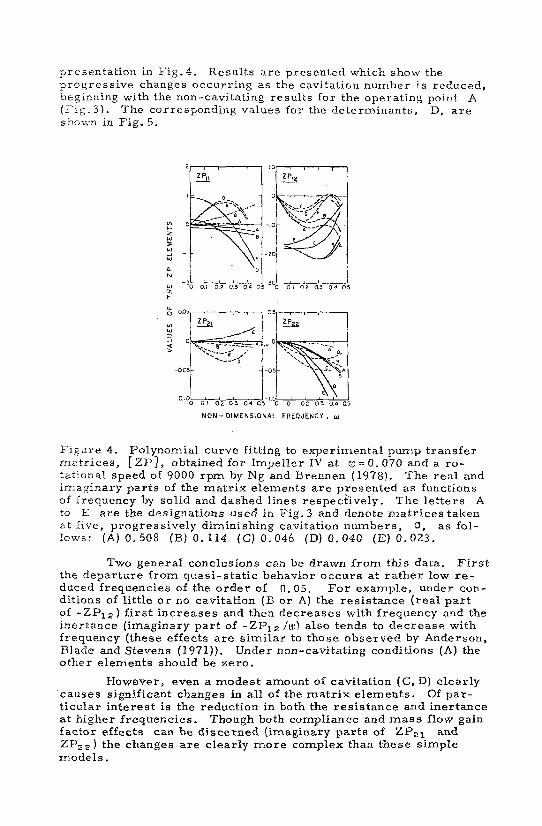

NON . DIMENSIONAL FREQUENCY , w
Figure 5. The determinants, D, for the results of Fig. 4; solidand dashed lines :gain represent rea l and imaginary par t s respectively.
The resul ts of Fig. 5, clearly demonstrate one of the most important conclusions, Though the pump acts like a dynamically passive device (with DFJ 1) under non-cavitating conditions even a modest amount of cavitation is sufficient to cauve the pump to become dynamically active. It should be noted f rom Fig. 3 that this occurs pr ior to any significant change in the steady state per- formance of the pump. Such a conclusiori has important conse- quences for the stability of hydraulic systems involving pumps and clearly demonstrates the need for dynamic pump models which incorporate this active dynamic characteristic.
5 . Theoretical Bubbly Flow Model
It has been established ear l ie r (Brennerl (1 973)) that a s t rcam o i cavitating bubbles exhibits a cumprcssibility o r compliance when subject to global p ressure fluctuations. This compliance remains rea l provided the fluctuation frequency i s well below the natural. resonant frequency of the bubble nuclei entering the cavitating region. Since these l a t te r frequencies a r e usually much larger than the fluctuation frequencies of concern here we may regard the cavita- ting bubbly flow a s similar to a two-phase mixture with some finite compressibili ty and sonic velocity. Thus the imposed fluctuations give r i s e to dynamic waves which propagate through the bubbly mixture in the blade passages of the impeller a t sonic velocity. Since this sonic velocity i s difficult to determine analytically with any degree of accuracy i t in represented in the theory by a com- pressibili ty parameter , K ( s e e Brennen (1978h)).
But the two-phase bubbly mixture in the blade passages is a l so subject to kinematic (or continuity) waves. These aregenerated by a fluctuating ra te of production of cavitation bubbles a t the inlet to the passages caused by the fluctuations in the angle of attack. The factor of proportionality i s difficult to determine analytically and is therefore represented by a parameter , M, in the theory.

Consequently a simple one-dimensional model of the bubbly flow in the blade passages was constructed and i ts dynamic response analyzed. Only a fraction, C, of the total length of the blade passage contains this bubbly flow. This fraction increases a s the cavitation number, 0, is decreased and i s therefore used in place of the mean flow variable, 0, for the purpose of presentation of the results in this paper. Thus, the flow through the impeller i s divided into four parts and dynamic relations for each part a r e used to synthesize the dynamics of the pump: (i) the relations between the upstream inlet fluctuations and those a t entrance to a blade passage (ii) the bubbly flow region within a blade passage (iii) the single phase liquid flow in the remainder of the blade pa s a g e following collapse of the cavities and (iv) the relations between the fluctuations a t the end of a blade passage and the down- s t ream conditions. Despite these complications i t t ranspires that the overall transfer function for the pump i s predominantly de- termined by the response of the bubbly region and the interactions between the upstream and downstream fluctuations caused by the dynamic and kinematic waves propagating through this region.
Some typical analytical t ransfer functions based on the model a r e presented in Fig. 6 for increasing values of E (de- creasing 5 ). The qualitative trends in the data with increasing frequency, W, a r e relatively independent of the choice of theparam- e ters K and M, though of course the quantitative magnitudes do depend on the particular values of these parameters.
NON- DIMENSIONAL FREQUENCY . W
Figure 6 . Theoretical pump transfer matrices ,[ZP], fo r Impeller IV a t rp = O . 07 a s functions of reduced frequency, W. The lettered curves a r e for different fractional lengths, C, of the bubbly region and correspond to decreasing cavitation numbers, 0:
(A) E = O . 2 (B) E =O. 4 ( C ) E = O . 6 (D) E =O. 8. The curves a r e for one specific choiceof the parameters, K and M (see Brennen (197833)).

Comparison with Fig. 4 suggests that this simple model has repro- duced most of the important trends in the t ransfer function a s both the frequency and cavitation number a r e changed. Since the indi- vidual clenlents of the t ransfer functions show satisfactory agreement, the analytical determinants a r e in similar agreement with the experimental resul ts of Fig . 5.
At present the mer i t of this analytical model i s that i t sug- gests qualitative reasons for the mechanics underl.ying the experi- mental results. F o r example, the "active" nature of the dynamics a r i s e s from the formation of kinematic waves a s the angle of attack fluctuates. Without this rnechahisnl the pump dynamics would be passive even under cavitating conditions, hlore detailed numerical comparison between theory and experiment requires further theoretical work an the values of K and M and further experi- mental exploration of the detailed processes occurring in the blade passages.
This work was supported by NASA George Marshall Space Flight Center under contract NAS 8-28046 and by the Natibnil Science Foundation under Grant Eng. 76-1 1225. The author a l so wishes to thank Professor Allan Acosta, David Braisted, Javier del Valle, George Hendrikvon and Philip Engalauf.
References
1. Farrelli, M. 1972. Furthor considerations on the dynamic be- havior of hydrwlic turbo-machinery. Water Power, June 1972. pp. 208-222.
2. Brennen, C. 1978a. The thermo-hydraulic t r a ~ s f e r functions fo r a phase change in a flowing fluid systc-m, Submitted for publi- cation.
3. Rubin, S . 1966, Longitudinal instability of llquid rockets due to propulsion feedback (POGO). J. Spacecraft and Rockets, Vol. 3 , No. 8, pp. 1188-1195.
4. Vaage, R.D., Fidlcr , L. E. and Zehnle, R.A. 1972. Investi- gation of character is t ics of feed system iustabi1itlt.s. Final Report MCR-72-107, Martin Marietta Corp. , Denver, Colorado.
5. Rocketdyne Report. 1969. Lr~vcstigation of 17-Hz, closed-loop instability on S-I1 stage of Saturn V. Rocketdyne Qiv. , Rockwell Iht'l. , Kept. No. R-7970.
6. Anderson, D. A. , Blade, R. J. and Stevens, W. 1971. Responce of a radial-bladed centrifugal pump to sinusoidal di3turbancc:s for non cavitating flow. NASA, T N D-6556.
7. Brennen, C., and Acosta, A. J. 1976. The dya rn i c t ransfer function fo r a cavitating inducer. J, Fluids Eng. , Vol. 98, pp. 182-191.
8. Brennen, C. 1973. The dynamic behavior and compliancc of a streamof cavitatingbubbles. J. Fluid3 Eng. , Vol. 95, Series 1, No. 4, pp. 533-542.

9. Ng. , S. L. 1976. Dynamic response of cavitating turbomachuirs. Ph. D. Thesis, Califoruia I n s t i t ~ t e of Tec;.rriology, Pasadena, Calif. , (Rept. E 184. 1 . Div. of Eng. and Appl. Sci. , C . I. T. , Auy. 1976). -
10. Ng. , S . L. and Drentrrn, C. 1918. Experiment:. on t1.e dyns~nic bchaviur of cavitating pu~l?tr. Subrr-itted tu J, F lu ids Eng.
1 1. B r e n n t . ~ ~ , C. 19'77. On no:^-cauitathg axial inducer per - forrnance, A srief, un?ublished tecluiical note.
12. Brais ted , D. M. and Brennen, C . 19.18. Observations on iastabilities of cavitating inducers. ASME Cavitation and Poly- phase Flow Forum, June 1978.
13. Brenner~, C. 1978b. Bubbly flow nlodel for the dynamic chdraeturistics of cavitat ing punlps. Submitted for publication.