procedure#: pb-2000 p & b testing, inc
TRANSCRIPT
NDE PROCEDURE P & B TESTING, INC. Destructive and Nondestructive Testing
Procedure#: PB-2000
Revision: A03
Page: 1 OF 17
Issue Date: 9/12/18
PB-2000
MAGNETIC PARTICLE TESTING
REVISION A03
SEPTEMBER 12, 2018
Reviewed By:
Buck Snider
Quality Manager
Date: September 12th, 2018
Approved By:
Scott Powers
ASNT NDT Level III 53325
Date: September 12th, 2018

NDE PROCEDURE P & B TESTING, INC. Destructive and Nondestructive Testing
Procedure#: PB-2000
Revision: A03
Page: 2 OF 17
Issue Date: 9/12/18
REVISION HISTORY
Revision Date Description of Changes Revised by
A0 01/01/96 Original Issue N/A
A01 12/30/99 Minor revision in various paragraphs as noted Scott Powers
A02 08/18/08 Major revision Scott Powers
A03 09/12/18 Reformatted and updated procedure Scott Powers
NDE PROCEDURE P & B TESTING, INC. Destructive and Nondestructive Testing
Procedure#: PB-2000
Revision: A03
Page: 3 OF 17
Issue Date: 9/12/18
TABLE OF CONTENTS
Section Title Page
0.0 Revision History 2
0.1 Table of Contents 3
1.0 Purpose 4
2.0 Personnel/Procedure Qualification 4
3.0 References 4
4.0 Equipment 5
5.0 Technique 7
6.0 Examination 10
7.0 Pre-Examination and Timing 10
8.0 De-magnetization 10
9.0 Surface Cleanliness and Finish 10
10.0 Coatings 10
11.0 Examination Method 11
12.0 Magnetic Field Strength 11
13.0 Particle Application 12
14.0 Evaluation 12
15.0 Process for Wet Particles 12
16.0 Reference Acceptance Criteria 13
17.0 Recording of Indications 14
18.0 Non-Conformance 14
19.0 Demagnetisation 14
20.0 Post Test Cleaning 15
21.0 Quality Control & System Performance 15
22.0 Suspension Vehicle Tests 15
23.0 Marking of Inspected Parts 16
24.0 Eye Glasses 16
25.0 Safety 16
26.0 Dark Eye Adaptation 16
27.0 Repairs 16
28.0 Documentation 17
NDE PROCEDURE P & B TESTING, INC. Destructive and Nondestructive Testing
Procedure#: PB-2000
Revision: A03
Page: 4 OF 17
Issue Date: 9/12/18
1.0 PURPOSE
1.1 This specification defines the requirements for the wet and dry magnetic particle
examination technique and procedure for inspection of specified welds, material and
components.
1.2 This specification is established to give instructions for inspection, detection and
evaluation of surface or slightly subsurface discontinuities in ferromagnetic materials
using the MT method.
2.0 PERSONNEL/PROCEDURE QUALIFICATION
2.1 Personnel performing inspection, evaluation and interpreting results in accordance with
this specification, applicable codes, standards, and customer acceptance criteria shall have
a minimum of NDE Level II certification. NDE personnel qualification and certifications
shall be in accordance with the requirements of P&B Testing, Inc written practice PB-
4000 which meets the requirements of ASNT SNT-TC-1A as a minimum.
2.2 NDE Level I may perform inspections and calibration of equipment if under direct
supervision of NDE Level II or Level III personnel, but shall not evaluate results with
respect to applicable codes, standards and customer acceptance criteria.
2.3 All third party inspection personnel shall adhere to this procedure for magnetic particle
examinations of Aker Solution’s products, unless customer contractual requirements
mandate the use of customer procedures or P&B Testing, Inc Quality Assurance Manager
and ASNT NDT Level III approve the use of a third party procedure in writing.
2.4 Quality Assurance Manager shall be responsible for all tests being performed in
accordance to this procedure.
2.5 Personnel qualifications, valid eye exams and certification shall be maintained on file.
3.0 REFERENCED DOCUMENTS
The following documents have been referenced in preparation of this procedure and are
considered part of it as applicable when required by contractual agreement or listed in the
purchase order.
ASTM E 709 Standard Guide for Magnetic Particle Examination
ASTM E 1444 Standard Practice for Magnetic Particle Examination
ASTM A 275 Standard Test Method for Magnetic Particle Examination of Steel
Forgings
ANSI/Z540-1 Calibration Laboratories and Measuring and Test Equipment
Examination
RP- SNT-TC-1A Recommended Practice for Personnel Qualification and Certification in
Non-destructive Testing
API 6A Specification for Wellhead and Christmas Tree Equipment
API 17D Specifications for Subsea Wellhead and Christmas Tree Equipment
AWS D1.1 Structural Weld Code-Steel
ASME V-Article 7 Magnetic Particle Examination
PB-4000 Written Practice
NDE PROCEDURE P & B TESTING, INC. Destructive and Nondestructive Testing
Procedure#: PB-2000
Revision: A03
Page: 5 OF 17
Issue Date: 9/12/18
4.0 EQUIPMENT
4.1 Magnetizing Equipment
4.1.1 Magnetizing equipment shall be capable of inducing a sufficient magnetic field
in two (2) directions approximately ninety degrees (90) apart from each other
using either circular or longitudinal method or both. Equipment may produce
direct current, alternating current, half wave direct, full wave direct, or half
wave rectified alternating current (HWAC).
4.1.2 Each piece of magnetizing equipment shall be calibrated at a minimum of once
every six (6) months or whenever there is reason to believe the equipment is
malfunctioning or repairs that could affect output have been made. Calibration
shall be done prior to its use.
Handheld yokes may be AC, DC or HWAC.
Cables may be copper or aluminium.
Coils shall consist of 3 turns minimum.
Clamps may be lead, copper or brass.
Prods are prohibited without written approval from Quality Assurance.
White Contrast Paint.
Wet or dry visible or fluorescent particles.
4.2 Yoke Equipment
4.2.1 Portable electromagnetic yokes (AC, DC or HWAC) maybe used as a
magnetizing apparatus, provided AC yokes lift a calibrated weight of at least
10lbs and the DC/HWAC lift a 40 lb weight minimum at the maximum pole
spaces to be used. If DC yoke poles are spaced four (4) to six (6) inches apart, a
50lb weight shall be used for calibration prior to the exam.
Note: When using DC or HWAC, 40lb weight is necessary to comply with
ASTM Section V Article 7 and 50lb weight is necessary for compliance to
ASTM E 709-01 as applicable.
Note: The use of Yoke Equipment on API Product is limited to localized areas
i.e. weld repair, spot-checking.
4.3 Field Indicator Equipment
4.3.1 To verify the adequacy of magnetic field strength, one or more of the following
three methods shall be used. When using a pie-shaped magnetic field indicator
or artificial flaw shim and the magnetic lines of flux can be clearly observed in
the desired direction, the field shall be considered sufficient to conduct the
examination. Only table three (3) is applicable for yokes, item one (1) and two
(2) below are not necessary when using the yoke technique.
Pie-Shaped Magnetic Particle Field Indicator.
Artificial Flaw Shims.
Hall Effect Probe Gauss-meter.
4.4 Magnetic Particle Materials and Vehicle
4.4.1 Particles used for the examination shall meet the following requirements.
NDE PROCEDURE P & B TESTING, INC. Destructive and Nondestructive Testing
Procedure#: PB-2000
Revision: A03
Page: 6 OF 17
Issue Date: 9/12/18
(a) Particle Types. The particles shall be treated to impart color (fluorescent pigments, nonfluorescent
pigments, or both) in order to make them highly visible (contrasting) against the background of the surface
being examined.
(b) Wet Particles requirements: the particles shall show indications as listed in Table 2 on the ketose test
ring specimen per ASTM E 1444. The suspension vehicle for the wet method shall be a light petroleum
distillate or water based and particle concentrations shall be from 0.1 to 0.4 ml in a 100-ml centrifuge tube
for fluorescent particles, and 1.2 to 2.4 ml for visible.
(c) Temperature Limitations; Examination surface shall not exceed125°F for wet particles and 350°F for
dry particles as measured with a suitable device.
4.5 Lighting
Visible Light – Visible light shall be used when examining with non-fluorescent particle
indications or evaluating fluorescent indications. The intensity of the visible light at the surface
of the part undergoing examination shall be maintained at a minimum of 100 ftc (1000 1x).
Ambient Visible Light – Fluorescent magnetic particle examinations shall be performed in a
darkened area with a maximum ambient visible light level of 2 ftc (20 1x) measured at the part.
Black Lights – All black lights shall be checked at the intervals specified in Table 1, and after bulb
replacement. The minimum acceptable intensity is 1000 W/cm2 at the part surface being
examined after the bulb has warmed up for a minimum of five (5) minutes. Black light
reflectors and filters shall be checked daily for cleanliness and integrity. Damaged or dirty
reflectors or filters shall be replaced or otherwise corrected as appropriate.
4.6 Calibration of Equipment
All the above mentioned items shall be verified and checked per the interval as stated in Table 1.
TABLE 1 Required System / Equipment Verification Intervals
Item Maximum Time Between
Verification
Verification Requirements
Lighting
Black Light Intensity * 1 Each Day 1000µW/cm²
Ambient Light Intensity * 1 Each Day 2 ft candles
Visible Light Intensity * 1 Each Day 100 ft candles
Particle Concentration (Fluorescent)* 1 Each Day 0.1 to 0.4 ml in 100-ml
Particle Concentration (Visible)* 1 Each Day 1.2 to 2.4 ml in 100-ml
System performance test piece or “Ketos
Ring” *
1 Each Day Refer to Table 2
Equipment Calibration Checks
Gauss Meter (Teslameter) Zero Prior to use Zeroed
AC Yoke Prior to use 10lbs Lift Test
DC/HWDC Yoke Prior to use 50lbs Lift Test
Equipment Accuracy Calibration
Gauss Meter (Teslameter) ** 6 Months Performed by Outside Vendor
Ammeter Accuracy ** 6 Months Performed by Outside Vendor
NDE PROCEDURE P & B TESTING, INC. Destructive and Nondestructive Testing
Procedure#: PB-2000
Revision: A03
Page: 7 OF 17
Issue Date: 9/12/18
Timer Control ** 6 Months Performed by Outside Vendor
Quick Break ** 6 Months Performed by Outside Vendor
* Results of Verification Shall be recorded on a “Daily Verification Log” Form-MT3
** The Maximum time between verifications may be reduced or extended when substantiated by actual
technical/reliability data.
5.0 TECHNIQUE
5.1 Direct Circular Magnetization
5.1.1 When magnetizing by passing current directly through the part (that is, using
head-shots), the current shall be from 300 to 800 A/in. of part diameter (12 to
32 A/mm). The diameter of the part shall be taken as the greatest distance
between any two points on the outside circumference of the part. Currents will
normally be 500 A/in. or higher currents (up to 800 A/in.) being used to inspect
low-permeability alloys such as precipitation-hardened steels.
5.2 Central Conductor Circular Magnetization
5.2.1 Circular magnetization may be provided by passing current through a conductor
that passes through the inside of the part. Alternating current shall be used to
inspect for surface or slight subsurface discontinuities on the inside surface of
the part. If only the inside of the part is to be inspected, the diameter shall be the
greatest distance between two points, 180 degrees apart on the inside
circumference. Otherwise, the diameter is determined as in 6.3.5. The
following two paragraphs cover centrally located and offset central conductors:
Centrally Located Conductor - When the axis of the central conductor is located
near the central axis of the part, the same current levels as given in 6.3.4 shall
apply.
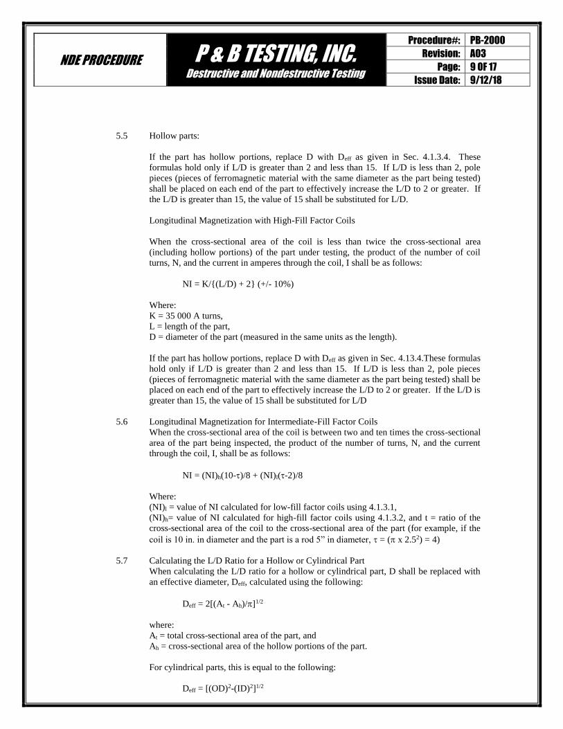
Offset Central Conductor - When the conductor is passing through the inside of
the part is placed against an inside wall of the part, the current levels as given in
6.3.5 shall apply. Except that the diameter shall be considered the sum of the
diameter of the central conductor and twice the wall thickness. The distance
along the part circumference (interior) that is effectively magnetized shall be
taken as four times the diameter of the central conductor, as illustrated in Fig. 3.
Rotating the part on the conductor, allowing for approximately a 10% magnetic
field overlap shall inspect the entire circumference.
4d
Figure 1 Approximate Effective Region of Examination when Using an Offset Central Conductor

NDE PROCEDURE P & B TESTING, INC. Destructive and Nondestructive Testing
Procedure#: PB-2000
Revision: A03
Page: 8 OF 17
Issue Date: 9/12/18
5.3 Longitudinal Magnetization
5.3.1 Longitudinal magnetization is often accomplished by passing current through a
coil encircling the part, or section of the part, to be tested (that is, by using a coil
shot). This produces a magnetic field parallel to the axis of the coil. For low or
intermediate fill factor coils, the effective field extends a distance on either side
of the coil center approximately equal to the radius of the coil. For a high-fill
factor coils, the effective distance of magnetization is 9 in. (230 mm) on either
side of the coil center (see Fig. 2). For parts longer than these effective
distances, repositioning the part with the coil, allowing for approximately 10%
effective magnetic field overlap shall inspect the entire length.
5.4 Effective Region of Inspection
9’’ 9’’
Figure 2 Effective Region of Inspection for a High Fill-Factor
5.4.1 Longitudinal Magnetization with Low-Fill Factor Coils
When the cross-sectional area of the coil is ten or more times the cross-sectional
area of the part being inspected, the product of the number of coil turns, N, and
the current in amperes through the coil, I, shall be as follows:
For parts positioned to the side of the coil:
NI = K/(L/D) (+/- 10%)
where:
N = number of turns in the coil,
I = coil current to be used, amperes (A),
K = 45 000 (empirically derived constant),
L = part, length
D = part diameter, (measured in the same units as the length)
NI = ampere turns.
For parts positioned in the center of the coil:
NI=KR/((6L/D)-5) ( 10%)
where:
N = number of turns in the coil,
I = coil current to be used, A,
K = 43 000 A turns per inch if R is measured in inches (1690 A turns per mm)
R = coil radius,
L = part length,
D = part diameter, (measured in the same unit as the length) NI = ampere turns.
NDE PROCEDURE P & B TESTING, INC. Destructive and Nondestructive Testing
Procedure#: PB-2000
Revision: A03
Page: 9 OF 17
Issue Date: 9/12/18
5.5 Hollow parts:
If the part has hollow portions, replace D with Deff as given in Sec. 4.1.3.4. These
formulas hold only if L/D is greater than 2 and less than 15. If L/D is less than 2, pole
pieces (pieces of ferromagnetic material with the same diameter as the part being tested)
shall be placed on each end of the part to effectively increase the L/D to 2 or greater. If
the L/D is greater than 15, the value of 15 shall be substituted for L/D.
Longitudinal Magnetization with High-Fill Factor Coils
When the cross-sectional area of the coil is less than twice the cross-sectional area
(including hollow portions) of the part under testing, the product of the number of coil
turns, N, and the current in amperes through the coil, I shall be as follows:
NI = K/{(L/D) + 2} (+/- 10%)
Where:
K = 35 000 A turns,
L = length of the part,
D = diameter of the part (measured in the same units as the length).
If the part has hollow portions, replace D with Deff as given in Sec. 4.13.4.These formulas
hold only if L/D is greater than 2 and less than 15. If L/D is less than 2, pole pieces
(pieces of ferromagnetic material with the same diameter as the part being tested) shall be
placed on each end of the part to effectively increase the L/D to 2 or greater. If the L/D is
greater than 15, the value of 15 shall be substituted for L/D
5.6 Longitudinal Magnetization for Intermediate-Fill Factor Coils
When the cross-sectional area of the coil is between two and ten times the cross-sectional
area of the part being inspected, the product of the number of turns, N, and the current
through the coil, I, shall be as follows:
NI = (NI)h(10-)/8 + (NI)l(-2)/8
Where:
(NI)l = value of NI calculated for low-fill factor coils using 4.1.3.1,
(NI)h= value of NI calculated for high-fill factor coils using 4.1.3.2, and t = ratio of the
cross-sectional area of the coil to the cross-sectional area of the part (for example, if the
coil is 10 in. in diameter and the part is a rod 5” in diameter, = ( x 2.52) = 4)
5.7 Calculating the L/D Ratio for a Hollow or Cylindrical Part
When calculating the L/D ratio for a hollow or cylindrical part, D shall be replaced with
an effective diameter, Deff, calculated using the following:
Deff = 2[(At - Ah)/]1/2
where:
At = total cross-sectional area of the part, and
Ah = cross-sectional area of the hollow portions of the part.
For cylindrical parts, this is equal to the following:
Deff = [(OD)2-(ID)2]1/2
NDE PROCEDURE P & B TESTING, INC. Destructive and Nondestructive Testing
Procedure#: PB-2000
Revision: A03
Page: 10 OF 17
Issue Date: 9/12/18
where:
OD = outside diameter of the cylinder, and
ID = inside diameter of the cylinder.
6.0 EXAMINATION
6.1 All testings shall be examined in accordance with the requirements of this specification
and the normative references unless otherwise specified. In case of conflict between this
procedure, customer requirements, or normative references, the more stringent shall
apply. Interpretations should be channelled through P&B Testing, Inc NDT Level III.
6.2 The continuous method shall be used for all magnetic particle examinations.
6.3 When any API specification is applicable, the continuous wet fluorescent method shall be
used.
6.4 All examinations shall be conducted in a manner that will ensure 100% coverage with
sufficient overlap.
The area(s) to be examined shall be determined by any one or more of the following;
router, PO, ITP, QP, drawing, engineering specification or contract.
7.0 PRE-EXAMINATION AND TIMING
7.1 When MT is specified, it shall be performed after the completion of operations that could
cause a surface or near-surface discontinuity. These operations include, but are not
limited to, forging, heat treating, cold forming, welding, grinding, straightening,
machining and proof loading.
For certain operations that may increase the parts susceptibility of delayed cracking, MT
shall be performed not less than 48 hours after the completion of the operations. These
shall be noted in one or more of the following; router, PO, ITP, QP, drawing, engineering
specification or contract.
8.0 DE-MAGNETIZATION
8.1 The part shall be demagnetized before examination if prior operations have produced a
residual magnetic field that may interfere with the examination. A residual field of three
(3) gauss or less is considered demagnetized.
9.0 SURFACE CLEANLINESS AND FINISH
9.1 The surface of the part to be examined, including adjacent areas within at least 1”
(25mm) of the examination area, shall be essentially smooth, clean, dry, and free of oil,
scale, machining marks, or other contaminants or conditions that might interfere with the
efficiency of the inspection.
9.2 All surfaces subject to MT shall have been found acceptable by visual inspection in
accordance with the applicable criteria. As rolled, as welded, as cast, as forged and as
machined conditions usually produce and acceptable surface for MT.
10.0 COATINGS
10.1 With written customer approval, MT may be conducted over some coatings if the
procedure is qualified under similar conditions and the below requirements are met.

NDE PROCEDURE P & B TESTING, INC. Destructive and Nondestructive Testing
Procedure#: PB-2000
Revision: A03
Page: 11 OF 17
Issue Date: 9/12/18
10.2 MT examination shall not be performed with coatings in place that could prevent the
detection of a surface discontinuity in ferromagnetic substrate. Such coatings normally
include paint or chrome plate greater than 0.002 in. (0.05 mm) in thickness, and
ferromagnetic coatings, such as electroplated nickel greater than 0.0008 in. (0.02 mm) in
thickness. When such coatings are nonconductive, they must be removed where
electrical contact is to be made. In high stress applications when detection of fine
discontinuity such as grinding cracks and non-metallic stringers is required, the coating
shall be removed.
10.3 No coating is allowed when a yoke is being used.
10.4 Thin layers of contrast paint may be applied to improve contrast between background and
magnetic particles except when prohibited by the customer.
11.0 EXAMINATION METHOD
11.1 Magnetization
11.2 Types of Magnetization: The types of current used for MT are rectified alternating (full
or half wave), direct current and alternating current.
11.3 When current is passed through the part itself, the equipment shall consist of contacting
or clamping elements with sufficient surface area and clamping pressure to allow the
required current to flow without damaging (burning) the part being examined.
11.4 Caution: Prod shall not be used.
11.5 Direction of Magnetization: Discontinuities are difficult to detect by the magnetic particle
method when they make an angle less than 45° to the direction of magnetization. To
ensure the detection of discontinuities in any direction, each part must be magnetized in
at least two directions. During the second examination, the lines of magnetic flux shall be
approximately perpendicular to those used during the first examination. Depending on
part geometry, this may consist of circular magnetization in two or more directions, of
both circular and longitudinal magnetization, or of longitudinal magnetization in two or
more directions.
12.0 MAGNETIC FIELD STRENGTH
12.1 The applied magnetic field applied magnetic field shall have sufficient strength to
produce satisfactory indications, but it must not be so strong that it causes the masking of
relevant indications by non-relevant accumulations of magnetic particles. Factors that
determine the required field strength include the size, shape, and material permeability of
the part, technique of magnetization, the method of particle application, and the type of
discontinuities sought.
12.2 Adequate field strength shall be demonstrated by the use of a field indicator as defined in
4.2 or applicable weight lift for yoke methods.
12.3 Excessive magnetic saturation may prove to leave an undesirable magnetic field that can
be very difficult to demagnetize.

NDE PROCEDURE P & B TESTING, INC. Destructive and Nondestructive Testing
Procedure#: PB-2000
Revision: A03
Page: 12 OF 17
Issue Date: 9/12/18
13.0 PARTICLE APPLICATION
13.1 Wet Continuous Magnetic Particle Method
13.1.1 The magnetic particles suspension at the required concentration, shall be applied
by spraying or flowing the suspension over the area to effectively cover all part
surfaces. Perform MT with sufficient magnetization to ensure that
discontinuities having axes in any direction will be detected. The magnetizing
current shall be applied for duration of at least ½ second for each application,
with a minimum of two shots being used and the last one applied immediately
after the suspension has been diverted.
13.2 Dry Magnetic Particle Continuous Method
.
13.2.1 Apply a light, uniform, dust-like coating of dry powder to the examination area
with a gentle air stream while magnetizing. Remove excess particles with a
gentle air stream and evaluate the magnetic particle indications. Repeat steps
approximately ninety (90) degrees from the original directions while ensuring
sufficient overlap.
14.0 EVALUATION
14.1 All indications shall be evaluated as relevant or non-relevant. Relevant indications are
produced by leakage fields which are the result of discontinuities. Non-relevant
indications can occur singly or in patterns as a result of leakage fields created by
conditions that require no evaluation such as changes in section (like keyways and drilled
holes), inherent material properties (like the edge of a bimetallic weld), magnetic writing,
etc. Relevant indications will be compared to applicable acceptance criteria and the
results will be recorded.
An indication whose length is equal to or greater than three times its width shall be
considered as linear.
An indication whose length is equal to or greater than three times its width shall be
considered as rounded.
Only indications with major dimensions greater than 1/16 inch shall be considered
relevant.
14.2 Any questionable or doubtful indications shall be re-examined to determine whether or
not they are relevant. If the indication is no longer present after re-examination, it shall be
considered nonrelevant.
14.3 Minor surface conditioning is an acceptable practice when conducting MT. Inherent
indications such as magnetic permeability variations and non-metallic stringers not
associated with surface rupture can be examined by liquid penetrant examination in
accordance with P&B Testing, Inc PT procedure PB-3000 to prove their relevancy or
removed by minor surface conditioning. In these cases, liquid penetrant results shall be
recorded and if significant material removal has occurred, a dimensional inspection shall
be conducted in accordance with applicable drawings. If indications do not bleed out with
liquid penetrant examination, they shall be considered nonrelevant.
15.0 PROCESS FOR WET PARTICLES
A. Surface preparation in accordance with this procedure.
B. Place the magnetizing unit on the examination surface.
C. Energize the unit creating the magnetic field. Maintain good contact with the examination
surface.
NDE PROCEDURE P & B TESTING, INC. Destructive and Nondestructive Testing
Procedure#: PB-2000
Revision: A03
Page: 13 OF 17
Issue Date: 9/12/18
D. Apply the wet magnetic particles using an aerosol can or mixture, which has been properly
agitated. Magnetization shall be applied throughout the duration of this process to ensure particle
mobility.
E. The wet particles may be applied just prior to or during the energizing of the magnetizing unit.
Care shall be taken to prevent high velocity flow over critical surfaces, and to cease application of
the wet suspension prior to removing the magnetizing force. The application and evaluation of
fluorescent particles shall be performed while the examination surface is illuminated by
ultraviolet light. The current can be terminated immediately after the wet particles have been
diverted.
F. Reposition the unit approximately 90 degrees to the initial direction of magnetization and repeat
steps 2 through 5.
G. Mark all indications exceeding the relevant acceptance standards.
16.0 REFERENCE ACCEPTANCE CRITERIA
The below is only for reference as applicable as it would be nearly impossible to list all of the
codes applicable to every part inspected by P&B Testing, Inc. True acceptance criteria shall be
determined by any one or more of the following; router, PO, ITP, QP, drawing, engineering
specification or contract. When adherence to a specific code or standard is required, verification of
the applicable revision level is mandatory. When the Level II is not certain which acceptance
criteria to apply to a specific part, he/she shall consult their Quality Manager for clarification.
16.1 Reference Criteria for Materials
For API 6A/API 17D, PSL 2, 3, and 4 materials:
No relevant linear indications.
No relevant rounded indication with a major dimension equal to or greater than
3/16".
No more than 10 relevant indications in any continuous 6-square inch area.
Four (4) or more relevant (linear or rounded) indications in a line separated by less
than 1/16" (edge to edge) are unacceptable.
No relevant indications in pressure contact sealing surfaces.
16.2 Criteria for Welds
16.2.1 Pressure containing welds per ASME X III code
All of the following shall be considered unacceptable:
Relevant linear indications 1/16 inch or greater.
Relevant round indications greater than 3/16 inch diameter (edge-to-edge).
Four or more relevant rounded indications in a line separated by 1/16 inch
(1.6 mm) or less (edge-to-edge).
Sealing surface shall be free of all relevant indications.
16.2.2 Structural welds per AWS D1.1 code
Evaluations shall be based on the AWS D1.1 requirements for visual inspection,
and the welds shall be acceptable if the criteria of ASW D1.1 Table 6.1 (or
corresponding part in the latest edition) are satisfied, which include:
Crack Prohibition
Weld/Base-metal Fusion
Crater Cross Section
Weld Profiles
Time of Inspection

NDE PROCEDURE P & B TESTING, INC. Destructive and Nondestructive Testing
Procedure#: PB-2000
Revision: A03
Page: 14 OF 17
Issue Date: 9/12/18
Underrun
Undercut
Porosity
16.2.3 Welds produced per API 17 D, API 6A
For welds produced under the requirements of API 17D, API 6A/ISO10423 - PSL 2, 3
and 4 (Overlays only) shall meet the requirements found in acceptance criteria for
material. For item B above, the following shall be adhered to:
No rounded indications greater than 1/8" for welds whose depth is 5/8" or less.
No rounded indications greater than 3/16" for welds whose depth are greater than
5/8”.
17.0 RECORDING OF INDICATIONS
17.1 The location of all relevant and unacceptable indications shall be marked on the part, and
permanent records of the location, direction, and frequency of indications shall be made
by one or more of the following methods:
A. Written Description: By recording the location, length, direction, and number of
indications in sketch or tabular form.
B. Any indication not meeting the acceptance criteria of, or deviating from referencing
specification or this specification shall be considered non-conforming and
unacceptable.
18.0 NON-CONFORMANCE
18.1 In the event an unacceptable indication is observed and it’s obvious it cannot be removed
by minor surface conditioning, an NCR shall be generated and forwarded to either or all
as documented in P&B Testing, Inc. facility procedures; cognizant engineer, customer,
quality manager or whomever else has been designated for disposition of non-
conformances of the part in question.
18.2 Nonconforming parts shall be identified and segregated until disposition has been
established by the appropriate personnel.
18.3 Non-conformance reports shall contain as much information as practical to assist with
the best disposition (e.g. size, shape, orientation, quantity, length, location, etc.).
Furthermore, the disposition NCR shall have sufficient instructions regarding repairs (e.g.
WPS #, method of indication removal, etc.).
19.0 DEMAGNETIZATION
19.1 Parts shall be carefully demagnetized between successive magnetizing operations
whenever the residual magnetization would interfere with the direction and strength of
the magnetic field in the next operation. After inspection, moving the part through a
demagnetizing AC coil or equivalent demagnetizing current method shall demagnetize
the parts The amount of magnetism remaining in a part after demagnetization shall not
exceed 3 Gauss (240 A·m-1), as determined by a field indicator or a Hall-effect probe
gauss-meter.
19.2 When using ac demagnetization, the part shall be subjected to a field with a peak value
greater than, and in nearly the same direction as, the field used during examination. This
ac field is then decreased gradually to zero. When using an ac demagnetizing coil, hold
the part approximately 1 ft (30 cm) in front of the coil and then move it slowly and
steadily through the coil and at least 3 ft (100 cm) beyond the end of the coil. Repeat

NDE PROCEDURE P & B TESTING, INC. Destructive and Nondestructive Testing
Procedure#: PB-2000
Revision: A03
Page: 15 OF 17
Issue Date: 9/12/18
this process as necessary. Rotate and tumble parts of complex configuration while
passing through the field of the coil.
19.3 When using dc magnetization, the initial field shall be higher than, and in nearly the same
direction as, the field reached during examination. The field shall then be reversed,
decreased in magnitude, and the process repeated (cycled) until an acceptably low value
of residual field is reached.
20.0 POST TEST CLEANING
20.1 After completion of the examination, interpretation, reporting and demagnetization, the
parts shall be thoroughly cleaned. Parts shall be protected from any possible corrosion or
damage during the cleaning process and shall be treated to prevent the occurrence of
corrosion after final inspection.
21.0 QUALITY CONTROL & SYSTEM PERFORMANCE
21.1 The overall performance of the magnetic particle examination system, including
the equipment, materials, and the lighting environment being used, shall be
verified initially and at regular intervals thereafter using Form-MT1 in the
Appendix. The required verification intervals are stated in Table 1. Records of
the verification results shall be maintained and retained for the time period
specified in the contract. Frequency of calibration used in the verification shall
comply with the requirements of Table 1, Calibrated using equipment traceable
to NIST or equivalent standard, at least once every (6) six months.
21.2 When using of test parts with discontinuities, a reliable method for inspection
system verification is to use the Ketos Ring, and the required indications are
stated in Table 2. The required verification intervals are stated in Table 1. If
correct magnetic particle indications can be produced and identified in the Ketos
Ring, the overall system and inspection procedure is verified. Demagnetize,
clean and check under black light, to ensure that residual indications do not
remain.
TABLE 2 Required Indications when Using the Ring Specimen
Central Conductor Minimum Number of
Particles Used FWDC Amperage Holes Indicated
Fluorescent, Visible Wet 1400 3
2500 5
3400 6
Reference Ketos ring per ASTM E 1444
22.0 SUSPENSION VEHICLE TESTS
Note: Not required for aerosol cans solution.
Particle concentration and contamination shall be determined upon start up, at regular intervals
thereafter, and whenever the bath is changed or adjusted. The required testing intervals are stated
in Table 1.
A. Determination of Wet Particle Concentration: Agitate the particle suspension a
minimum of 30 min. to ensure uniform distribution of particles throughout the bath.
NDE PROCEDURE P & B TESTING, INC. Destructive and Nondestructive Testing
Procedure#: PB-2000
Revision: A03
Page: 16 OF 17
Issue Date: 9/12/18
Place a 100-mL sample of the agitated suspension in a pear-shaped centrifuge tube.
Demagnetize the sample and allow the tube to stand undisturbed for at least 60 min.
for Oil Based Carriers and 30 min. for Water Based Carriers. Read the volume of
settled particles. If the concentration is out of the tolerance stated in the written
procedure, add the particles or suspension vehicle, as required, and predetermine the
particle concentration. If the settled particles appear to be loose agglomerates rather
than a solid layer, take a second sample. If the second sample also appears
agglomerated, replace the entire suspension.
B. Determination of Wet Particle Contamination: Perform the tests specified in the
Paragraph above (Sec.1). In addition, for fluorescent baths, examine the liquid
above the precipitate with black light. The liquid shall be comparable to the
fluorescence of the original solution. Examine the graduated portion of the tube,
under both black light (for fluorescent baths only) and visible light fluorescent, for
striations or bands, different in color or appearance. Bands or striations may indicate
contamination. If the total volume of the contaminants, including bands or striations,
exceeds 30% of the volume of magnetic particles, or if the liquid is noticeably
fluorescent, the bath must be replaced.
23.0 MARKING OF INSPECTED PARTS
23.1 Parts that have been accepted using magnetic particle examination shall be marked. The
marking shall be applied in such a manner and location as to be harmless to the part. The
identification shall not be obliterated or smeared by subsequent handling and, when
practicable, placed in a location that will be visible after assembly. When subsequent
processing would remove the identification, the applicable marking shall be affixed to the
record accompanying the finished parts or assembly. The letter “M” with a circle around
it will be employed to indicate a 100% acceptable inspection.
23.2 Records of calibration for the equipment, system test, material, technique, and procedure
checks shall be maintained and retained in the Quality Assurance files for traceability
purpose during the time period specified in the contract.
24.0 EYE GLASSES
When using fluorescent materials, inspectors shall not wear eyeglasses that are photo chromic or
that have permanently darkened lenses. Inspectors shall wear prescription eye glasses when noted
on their eye exam certificate.
25.0 SAFETY
25.1 Always use proper eye protection and clothing, safe handling practices of magnetic
particles/chemicals according to the supplied Material Safety Data Sheet (MSDS), proper
operating of equipment shall be always kept in mind.
26.0 DARK EYE ADAPTATION
26.1 Personnel must wait at least 1 min. after entering a darkened area for their eyes to adjust
to the low-level lighting before performing fluorescent magnetic particle examination.
27.0 REPAIRS
27.1 Unacceptable discontinuity shall be removed prior to the repair. Whenever an indication
is removed and subsequent repair by welding is required, the excavated area shall be re-
examined to assure complete removal of the indication prior to welding.

NDE PROCEDURE P & B TESTING, INC. Destructive and Nondestructive Testing
Procedure#: PB-2000
Revision: A03
Page: 17 OF 17
Issue Date: 9/12/18
28.0 DOCUMENTATION
28.1 The results of all magnetic particle inspection shall be recorded. All recorded results shall
be identified, filed, and made available for review by the customer upon request. The
following shall be recorded and maintained, in a traceable manner in Quality Assurance
files:
Procedure Number and Revision Level
Equipment and Calibration Date of Equipment
Magnetic Particle Report Number
Materials Type
Current Level/Type of Field Indication (Yoke) Used
Particle Type and Color
Technique Used
Job Number
Part Number
Serial Number
Date Performed
Evaluation and Disposition
Technician’s NDE Level Certification, Signature and Date
Form-MT1: Daily Inspection Log (System Performance)