pro-reel · 2019-05-07 · refining in order to operate as desired. optional equipment: a range of...
TRANSCRIPT

1
Pro-ReelOperator’s & Parts Manual
GA8700XXX REV 1.0 JAN 17
200L - GA4914035300L - GA4914040400L - GA4914045600L - GA4914050800L - GA4914055
400L Twin - GA4914070600L Twin- GA4914075800L Twin- GA49140801000L Twin- GA4914085
2
ContactGoldacres1-3 Morang Crescent, Mitchell Park Vic 3355P: 03 5342 6399 F: 03 5342 6308 [email protected]
Please note: All information in this operator’s manual is based on the latest product information available at the time of printing. The policy of Goldacres is one of continuous improvement and as such, Goldacres reserve the right to alter any specifications and designs without notice and without incurring any obligation regarding such changes. No part of this manual may be reproduced without written permission from Goldacres. All photographs and technical information remain the property of Goldacres.
General Information & Specs . . . . . . . . . . . .3Identification . . . . . . . . . . . . . . . . . . . . . . . . .3Dimensions . . . . . . . . . . . . . . . . . . . . . . . . . .4Key features . . . . . . . . . . . . . . . . . . . . . . . . . .5Pre Operation . . . . . . . . . . . . . . . . . . . . . . . . .6Following delivery . . . . . . . . . . . . . . . . . . . . .6Tasks prior to spraying . . . . . . . . . . . . . . . . .6Operation . . . . . . . . . . . . . . . . . . . . . . . . . . . .7Filling . . . . . . . . . . . . . . . . . . . . . . . . . . . . . . .7After spray application . . . . . . . . . . . . . . . . .8Transporting the sprayer . . . . . . . . . . . . . . .9Maintenance and Troubleshooting . . . . . . .9Manual Controls . . . . . . . . . . . . . . . . . . . . . .9DL Controller . . . . . . . . . . . . . . . . . . . . . . . . .9Calibrating your sprayer . . . . . . . . . . . . . . .10Nozzle Calibration . . . . . . . . . . . . . . . . . . . .10Operating the Chem Probe . . . . . . . . . . . . .11Filters . . . . . . . . . . . . . . . . . . . . . . . . . . . . . .12Diaphragm pumps . . . . . . . . . . . . . . . . . . . .14IOTA 20 PUMP Gear Box & Honda GX100 engine . . . . . . . . . . . . . . . . . .16
IOTA 20 . . . . . . . . . . . . . . . . . . . . . . . . . . . . .17Kappa 40 / Delta 40 PUMP Gear Box & Honda GX200 engine . . . . . . . . . . . . . . . . . .18Kappa 40 / Delta 40 . . . . . . . . . . . . . . . . . . .19Troubleshooting . . . . . . . . . . . . . . . . . . . . . .20Diaphragm Pump . . . . . . . . . . . . . . . . . . . . .2030mt manual hose reel . . . . . . . . . . . . . . . .21AA30L GunJet . . . . . . . . . . . . . . . . . . . . . . .22Adjustable ConeJet Nozzle . . . . . . . . . . . .23Safety Decals . . . . . . . . . . . . . . . . . . . . . . . .23Venturi Filler . . . . . . . . . . . . . . . . . . . . . . . . .24Chem Probe Assembly . . . . . . . . . . . . . . . .25Safety . . . . . . . . . . . . . . . . . . . . . . . . . . . . . .26The Operator . . . . . . . . . . . . . . . . . . . . . . . .26Safety Precautions . . . . . . . . . . . . . . . . . . .26Safe use of chemicals . . . . . . . . . . . . . . . . .28Personal Protective Equipment (PPE) . . .28Warranty . . . . . . . . . . . . . . . . . . . . . . . . . . . .28Goldacres Warranty Statement . . . . . . . . .29Terms & conditions . . . . . . . . . . . . . . . . . . .30

3
General Information and SpecsGeneralThe tray mount sprayer is ideal for small acreage and hard to get areas. Our Traymount range feature engine driven diaphragm pumps with pressure ranges from 290 –580 Psi.Our tray mount range are durable with a steel frame and our tanks are industrial grade UV protected polyethylene. Our range can be fitted with a host of booms and other handy options to make your spraying tasks easier.Know Your SprayerGetting to know your sprayer prior to operation is crucial in the safe and efficient operation of this equipment. Take the time to familiarise yourself with all the standard and optional components fitted to your sprayer, not only do you need to know where key components are located on your machine you need to become competent in the correct operation of these components prior to spraying operation. It is also important to become familiar with common spraying methods and common spraying terms prior to using this sprayer for the first time Chassis:The chassis is an all steel construction, that is fully welded for superior strength. The chassis is shot blasted, primed and then protected by the Goldacres paint process for excellent chemical resistance and durability.Paint Colours:Steel work: G13 Dark GreenTank:All tanks are constructed from UV resistant polyethylene. Polyethylene tanks have a very high chemical resistance. Due to the rotomoulding process, there can be a variance in the overall dimensions of the tank which in turn results in variations to the tank capacity. For this reason, calibration markings should be used as a guide only.Machine limitations:All Goldacres equipment is subject to operating limitations, it is the operator’s responsibiilty to ensure that this equipment is being operated within these limitations and
appropriately to the operating conditions at hand.Custom built equipment:Where the owner of this sprayer has requested that custom built equipment or options be fitted to this sprayer it is necessary to understand that custom fabrication and engineering is subject to many variables. Goldacres cannot fully field test all custom built options prior to despatch, and owners of new sprayers fitted with custom built equipment or options need to understand that the functionality of these items may require refining in order to operate as desired.Optional equipment:A range of optional equipment is available for fitting to Goldacres sprayers. Specific information regarding optional equipment fitted to your machine can be found in the rear of this manual.WARNINGSSee page 29 for more info.
Identification When ordering parts or requesting service information for your sprayer it is important to quote the serial number of your machine, and the purchase date, in order to receive accurate information. The location of the serial number plate on your machine is shown in the picture.

4
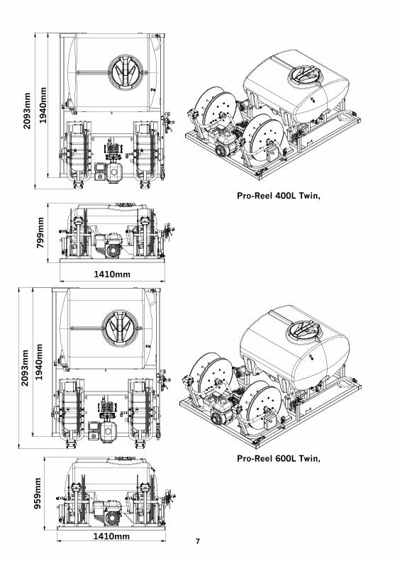
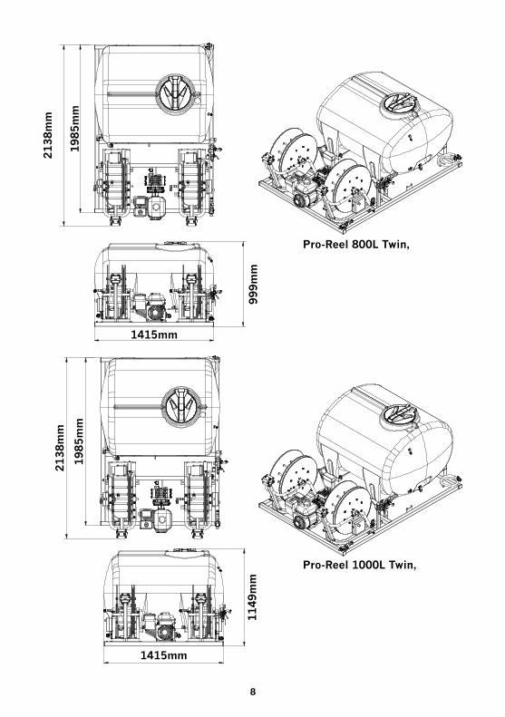
Dimensions
1030mm
1030mm
Pro-Reel 200L,
Pro-Reel 300L,
1483m
m
1350m
m1390m
m
1483m
m
1350m
m1390m
m
771m
m
575m
m
720m
m

5
1030mm Pro-Reel 400L,
Pro-Reel 600L,
1453m
m
1350m
m1390m
m
885m
m

6
Pro-Reel 800L,
7
Pro-Reel 400L Twin,
Pro-Reel 600L Twin,
1410mm
1410mm
1940m
m799m
m959m
m1940m
m2093m
m2093m
m
8
Pro-Reel 800L Twin,
Pro-Reel 1000L Twin,
1415mm
1415mm
1985m
m1985m
m
999m
m1149m
m
2138m
m2138m
m

9
10
Parts OrderingWhen ordering parts from your Goldacres dealer, please quote:Serial NoPart no requiredPart descriptionQuantity requiredWhen returning parts to Goldacres, or a Goldacres dealer, for service or repair all parts MUST be cleaned thoroughly before sending them. Goldacres cannot expose technicians to the many potentially hazardous pesticides and substances that are in use.
NOTE:Please ensure that all parts are clearly labelled with the owner’s details, and a brief description of the fault. Glodacres is not liable for the return of any goods to Goldacres or a Goldacres Dealer. The goods must be returned to the point of sale. The customer will be responsible for any cost incurred by a Goldacres appointed person travelling to any site outside the point of sale.Genuine Goldacres parts only should be used on Goldacres equipment.
11
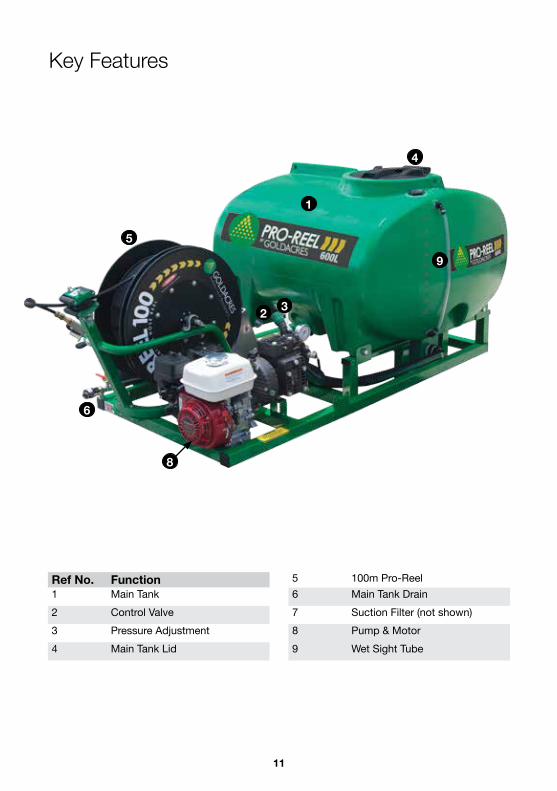
Key Features
Ref No . Function1 Main Tank2 Control Valve3 Pressure Adjustment4 Main Tank Lid
5 100m Pro-Reel6 Main Tank Drain7 Suction Filter (not shown)8 Pump & Motor9 Wet Sight Tube
8
9
1
2
4
5
6
3
12
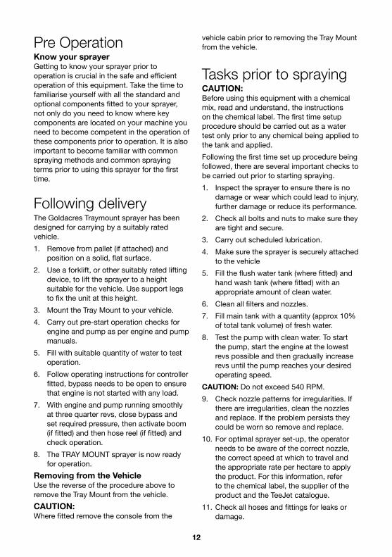
Pre OperationKnow your sprayerGetting to know your sprayer prior to operation is crucial in the safe and efficient operation of this equipment. Take the time to familiarise yourself with all the standard and optional components fitted to your sprayer, not only do you need to know where key components are located on your machine you need to become competent in the operation of these components prior to operation. It is also important to become familiar with common spraying methods and common spraying terms prior to using this sprayer for the first time.
Following deliveryThe Goldacres Traymount sprayer has been designed for carrying by a suitably rated vehicle.1. Remove from pallet (if attached) and
position on a solid, flat surface.2. Use a forklift, or other suitably rated lifting
device, to lift the sprayer to a height suitable for the vehicle. Use support legs to fix the unit at this height.
3. Mount the Tray Mount to your vehicle.4. Carry out pre-start operation checks for
engine and pump as per engine and pump manuals.
5. Fill with suitable quantity of water to test operation.
6. Follow operating instructions for controller fitted, bypass needs to be open to ensure that engine is not started with any load.
7. With engine and pump running smoothly at three quarter revs, close bypass and set required pressure, then activate boom (if fitted) and then hose reel (if fitted) and check operation.
8. The TRAY MOUNT sprayer is now ready for operation.
Removing from the VehicleUse the reverse of the procedure above to remove the Tray Mount from the vehicle.CAUTION:Where fitted remove the console from the
vehicle cabin prior to removing the Tray Mount from the vehicle.
Tasks prior to sprayingCAUTION: Before using this equipment with a chemical mix, read and understand, the instructions on the chemical label. The first time setup procedure should be carried out as a water test only prior to any chemical being applied to the tank and applied.Following the first time set up procedure being followed, there are several important checks to be carried out prior to starting spraying.1. Inspect the sprayer to ensure there is no
damage or wear which could lead to injury, further damage or reduce its performance.
2. Check all bolts and nuts to make sure they are tight and secure.
3. Carry out scheduled lubrication.4. Make sure the sprayer is securely attached
to the vehicle5. Fill the flush water tank (where fitted) and
hand wash tank (where fitted) with an appropriate amount of clean water.
6. Clean all filters and nozzles.7. Fill main tank with a quantity (approx 10%
of total tank volume) of fresh water.8. Test the pump with clean water. To start
the pump, start the engine at the lowest revs possible and then gradually increase revs until the pump reaches your desired operating speed.
CAUTION: Do not exceed 540 RPM.9. Check nozzle patterns for irregularities. If
there are irregularities, clean the nozzles and replace. If the problem persists they could be worn so remove and replace.
10. For optimal sprayer set-up, the operator needs to be aware of the correct nozzle, the correct speed at which to travel and the appropriate rate per hectare to apply the product. For this information, refer to the chemical label, the supplier of the product and the TeeJet catalogue.
11. Check all hoses and fittings for leaks or damage.

13
12. Follow the chemical label and ensure that you follow the specified mixing procedure for addition of chemicals to main tank.
13. When mixing procedure has been followed, fill main tank with appropriate quantity of water required for task at hand.
14. CAUTION: Traymount sprayers fitted with manual hose reels should not exceed 160 psi maximum spraying pressure. If the unit is fitted with a Pro Reel automatic rewind hose reel the maximum operating pressure is 300 psi.
WARNING: When filling tanks with water, 1 litre of water will add 1 kg of weight. Some chemicals weigh more than water, therefore it is the operators responsibility to ensure the loaded weight of the sprayer does not exceed the towing and / or carrying capacity of the vehicle.15. You are now ready to start using the
sprayer
OperationGeneralBefore attempting to use your sprayer with any chemicals, the application rate in litres per hectare and the droplet spectrum need to be considered. This information should be readily available from your agronomist and by referring to the chemical label.NOTE: Allow the pump to agitate the tank mixture while filling. It is normal practice to agitate the spray mixture before spraying. The chemicals need to mix uniformly throughout the spray mixture in order to achieve a correct spray application. Agitation is primarily a function of pump capacity, such that the larger the pump the greater the amount of bypass and hence the greater amount of agitation for a given spraying application.ConnectionsThe following steps should be followed when connecting to a power source:1. Ensure that the battery is 12V DC2. Connect the red connector to the positive
(+) terminal and the black connector to the negative (-) terminal.
CalibrationAll sprayers need to be calibrated and kept in good condition. This will ensure that the correct rate of chemical is applied to the target. Follow these steps to calibrate the sprayer:1. Measure the spray width of the nozzle on a
dry surface (in metres)2. Spray a test area at the intended pressure
and speed. Record distance (in metres) covered in one minute (minute)
3. Measure the nozzle output in litres over one minute in a measuring jug (l/min)
The spray volume can be calculated by the following formula:Application Nozzle output (l/min) x 10,000 rate (L/Ha)
= Spray width (m) x speed (m/min)
Filling1. Add 20 per cent of the tanks volume of
clean water to the main spray tank.2. Carefully add all chemicals (more water
may be needed in the tank initially if adding granular or powder chemicals).
3. Add the remaining water (this will then help to mix the chemicals).
4. Agitate with pump at operating speed (maximum 540 RPM).
5. Check to ensure agitator is working (if fitted). There should be visible circulation of water near the back of the tank near the agitator.
14
After spray applicationCAUTION:Refer to chemical label for correct disposal of chemical residue.Drain out any chemical residue in the tank through the drain tap.Flush main tank:1. With the main tank drained, rinse the
inside of the tank with clean fresh water. As a guide, use 20% of the tanks volume for flushing.
2. With fresh water in the spray tank, operate the pump to clear chemical residue from the lines, then open the boom valves to allow the nozzles to be flushed.
CAUTION:Refer to chemical label for correct disposal of chemical residue.Refer to chemical label for correct decontamination procedure when decontamination is required.
Transporting the sprayerMake sure the vehicle has sufficient lifting and braking capacity to carry the sprayer.All relevant transport regulations must be adhered to when transporting the sprayer. (ie: speed regulations, oversize signs, flashing light, etc.) It is the operator’s responsibility to know the relevant regulations. Make sure the sprayer is securely attached to the vehicle as shown below.CAUTION:Take care when reversing the vehicle with the sprayer attached. If driver visibility is restricted use another adult, with a clear view to the rear of the sprayer, to give reversing directions.CAUTION:It is the operator’s responsibility to know the tare weight and gross weight of the sprayer.Contact Goldacres dealer to ascertain a more precise tare weight for your sprayer if unsure. If any alterations are made to the sprayer, it is the operator’s responsibility to know the tare weight and the gross weight of the modified sprayer at all times.NOTE: Store the sprayer in a suitable location
to prevent freezing. If the sprayer is to be left where freezing may occur, cover the pump and flow meter with a material bag and empty pump and flow meter of all water (run the pump dry for 15-20 seconds). Make sure any ice has thawed before using sprayer. Ensure the main tank and any other tanks fitted are empty.End of Season TasksIf the sprayer is to be stored for a long period of time without use, there are several tasks that need to be performed.• Clean the sprayer thoroughly as described
under “End of Spraying Day Tasks”.• Follow end of season storage instructions
for the engine (where fitted) as per the engine manufacturers operator manual supplied.
• With the sprayer attached to the carrying vehicle, carry out a thorough observation to determine if there is any damage to the sprayer.
• Store the sprayer in a position where it will not be affected by frosts, and preferably out of direct sunlight.
• Ensure the main tank and any other tanks fitted are empty.
Maintenance and TroubleshootingPump Information (Diaphragm pumps)The pump is critical to any sprayer performance. Correct operation and maintenance of the pump will ensure the sprayer is able to perform to its capabilities. Flushing the pump system with fresh water:To flush the pump system, use the procedure described under the using your sprayer section of this manual for “Flushing”.NOTE: Never overfill pump with oil as damage to seals and oil bowl may result.The pump will perform optimally operating between 400 and 540 RPM. 500 RPM is approximately three quarter revs on the engine.At lower revs excessive pulsation will occur, while pump and diaphragm damage can result at higher revs.

15
Manual ControlsA general explanation of manual controller functions are as follows:Pressure Relief Valve The pressure relief valve provides relief when the pressure exceeds a pre-determined value. Altering the adjusting stem will affect the setting at which the relief valve will come into operation. Turning the stem clockwise will increase the pressure relief setting. The pressure gauge gives indication of the delivery pressure to the boom or gunjet.By-Pass ValveThe By-pass valve enables all pump delivery to bypass back to the tank. The by-pass valve should be engaged when starting the pump with an engine so that the engine does not
start under load. The by-pass valve should also be engaged when wanting to agitate the tank mixture when not spraying. To engage the by-pass valve, pull the valve lever out. This will cause all pump delivery to be bypassed back to the tank. To disengage the by-pass valve, push the valve lever in, so that the pump delivery is directed out to the spray linesBoom / Attachment Levers The boom/attachment levers (number fitted dependent on options specified) open or close flow to the appropriate boom section/s or attachment/s as labeled. Pull the lever to the ON position in order to direct flow from the pump to the required function. Push the lever to the OFF position to stop flow going to the attachment that is now not required.
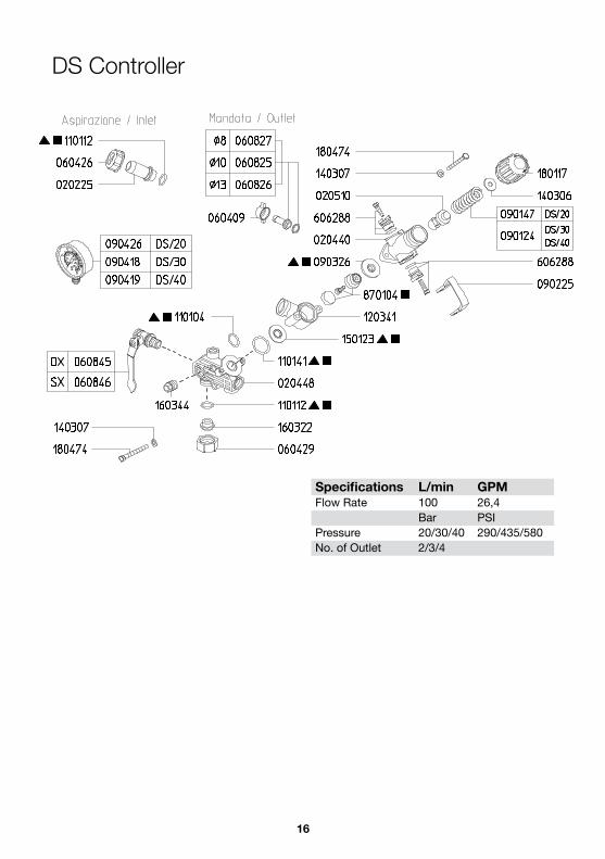
DS Controller
Specifications L/min GPMFlow Rate 100 26,4
Bar PSIPressure 20/30/40 290/435/580No. of Outlet 2/3/4
16
DS Controller
Specifications L/min GPMFlow Rate 100 26,4
Bar PSIPressure 20/30/40 290/435/580No. of Outlet 2/3/4
17
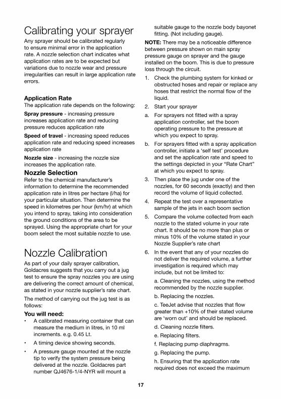
Calibrating your sprayerAny sprayer should be calibrated regularly to ensure minimal error in the application rate. A nozzle selection chart indicates what application rates are to be expected but variations due to nozzle wear and pressure irregularities can result in large application rate errors.
Application RateThe application rate depends on the following: Spray pressure - increasing pressure increases application rate and reducing pressure reduces application rate Speed of travel - increasing speed reduces application rate and reducing speed increases application rateNozzle size - increasing the nozzle size increases the application rate. Nozzle Selection Refer to the chemical manufacturer’s information to determine the recommended application rate in litres per hectare (l/ha) for your particular situation. Then determine the speed in kilometres per hour (km/hr) at which you intend to spray, taking into consideration the ground conditions of the area to be sprayed. Using the appropriate chart for your boom select the most suitable nozzle to use.
Nozzle CalibrationAs part of your daily sprayer calibration, Goldacres suggests that you carry out a jug test to ensure the spray nozzles you are using are delivering the correct amount of chemical, as stated in your nozzle supplier’s rate chart. The method of carrying out the jug test is as follows:You will need:• A calibrated measuring container that can
measure the medium in litres, in 10 ml increments. e.g. 0.45 Lt.
• A timing device showing seconds.• A pressure gauge mounted at the nozzle
tip to verify the system pressure being delivered at the nozzle. Goldacres part number QJ4676-1/4-NYR will mount a
suitable gauge to the nozzle body bayonet fitting. (Not including gauge).
NOTE: There may be a noticeable difference between pressure shown on main spray pressure gauge on sprayer and the gauge installed on the boom. This is due to pressure loss through the circuit.1. Check the plumbing system for kinked or
obstructed hoses and repair or replace any hoses that restrict the normal flow of the liquid.
2. Start your sprayera. For sprayers not fitted with a spray
application controller, set the boom operating pressure to the pressure at which you expect to spray.
b. For sprayers fitted with a spray application controller, initiate a ‘self test’ procedure and set the application rate and speed to the settings depicted in your “Rate Chart” at which you expect to spray.
3. Then place the jug under one of the nozzles, for 60 seconds (exactly) and then record the volume of liquid collected.
4. Repeat the test over a representative sample of the jets in each boom section
5. Compare the volume collected from each nozzle to the stated volume in your rate chart. It should be no more than plus or minus 10% of the volume stated in your Nozzle Supplier’s rate chart
6. In the event that any of your nozzles do not deliver the required volume, a further investigation is required which may include, but not be limited to:
a. Cleaning the nozzles, using the method recommended by the nozzle supplier.
b. Replacing the nozzles. c. TeeJet advise that nozzles that flow
greater than +10% of their stated volume are ‘worn out’ and should be replaced.
d. Cleaning nozzle filters. e. Replacing filters. f. Replacing pump diaphragms. g. Replacing the pump. h. Ensuring that the application rate
required does not exceed the maximum

18
flow and pressure parameters of the sprayer. Filters
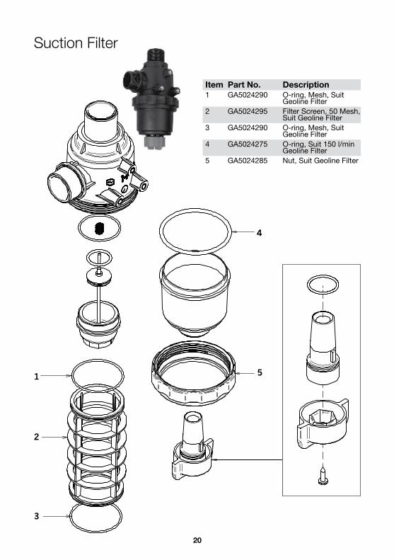
General InformationWARNING: Ensure that operator’s wear the appropriate PPE when cleaning filters. It is essential to maintain all filters, and filter screens, in good condition. Filter screens that are not regularly cleaned can severely impede the flow and thus affect delivery pressure. If the screen is in any way damaged, it can allow foreign material into the pumping system which can result in damage to the pump, solenoids, valves and nozzle tips. If the screen is not properly fitted, it can allow air into the pumping lines which will reduce the performance of the pump. The filter screen should be cleaned after every spraying operation. The best way to clean the filter screen is with a soft brush or compressed air after washing the entire chemical residue from the pump. Safety Shut-Off ValveThe safety shut off valve enables the filter bowl to be removed while automatically shutting off the supply line to the filter. As the filter bowl is removed (with the bowl cap), the valve plunger seats so as to seal off the filter from the supply line. Replacing the filter bowl unseats the valve plunger and thus opens the supply line to the filter. 314 Suction filterTo clean the suction filter:1. Wear all necessary protective clothing;2. Ensure the pump is turned off3. Carefully unscrew filter nut and remove
bowl;4. Remove screen and clean (with a soft
brush or compressed air);5. Check for damage to screen, bowl,body
and ‘o’ ring;6. Place screen back in position;7. Make sure ‘o’ ring is in position for proper
seal;8. Replace bowl and screw nut on;9. Do not over-tighten nut.

19
20
Item Part No . Description1 GA5024290 O-ring, Mesh, Suit
Geoline Filter2 GA5024295 Filter Screen, 50 Mesh,
Suit Geoline Filter3 GA5024290 O-ring, Mesh, Suit
Geoline Filter4 GA5024275 O-ring, Suit 150 l/min
Geoline Filter5 GA5024285 Nut, Suit Geoline Filter
5
4
3
2
1
Suction Filter
21
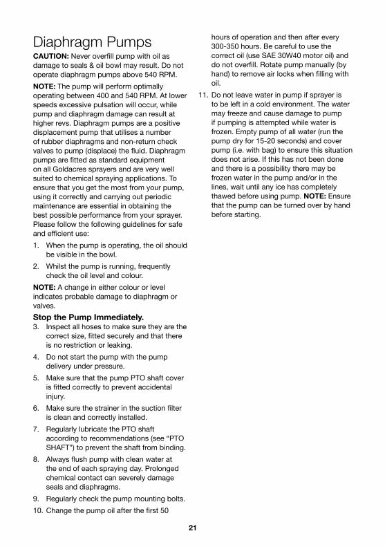
Diaphragm PumpsCAUTION: Never overfill pump with oil as damage to seals & oil bowl may result. Do not operate diaphragm pumps above 540 RPM.NOTE: The pump will perform optimally operating between 400 and 540 RPM. At lower speeds excessive pulsation will occur, while pump and diaphragm damage can result at higher revs. Diaphragm pumps are a positive displacement pump that utilises a number of rubber diaphragms and non-return check valves to pump (displace) the fluid. Diaphragm pumps are fitted as standard equipment on all Goldacres sprayers and are very well suited to chemical spraying applications. To ensure that you get the most from your pump, using it correctly and carrying out periodic maintenance are essential in obtaining the best possible performance from your sprayer. Please follow the following guidelines for safe and efficient use:1. When the pump is operating, the oil should
be visible in the bowl.2. Whilst the pump is running, frequently
check the oil level and colour.NOTE: A change in either colour or level indicates probable damage to diaphragm or valves.Stop the Pump Immediately .3. Inspect all hoses to make sure they are the
correct size, fitted securely and that there is no restriction or leaking.
4. Do not start the pump with the pump delivery under pressure.
5. Make sure that the pump PTO shaft cover is fitted correctly to prevent accidental injury.
6. Make sure the strainer in the suction filter is clean and correctly installed.
7. Regularly lubricate the PTO shaft according to recommendations (see “PTO SHAFT”) to prevent the shaft from binding.
8. Always flush pump with clean water at the end of each spraying day. Prolonged chemical contact can severely damage seals and diaphragms.
9. Regularly check the pump mounting bolts.10. Change the pump oil after the first 50
hours of operation and then after every 300-350 hours. Be careful to use the correct oil (use SAE 30W40 motor oil) and do not overfill. Rotate pump manually (by hand) to remove air locks when filling with oil.
11. Do not leave water in pump if sprayer is to be left in a cold environment. The water may freeze and cause damage to pump if pumping is attempted while water is frozen. Empty pump of all water (run the pump dry for 15-20 seconds) and cover pump (i.e. with bag) to ensure this situation does not arise. If this has not been done and there is a possibility there may be frozen water in the pump and/or in the lines, wait until any ice has completely thawed before using pump. NOTE: Ensure that the pump can be turned over by hand before starting.

22
Pump DiaphragmsThe pump diaphragms are wearing components that need to be replaced during the life of the pump. Life expectancy depends upon the operation and maintenance and its suitability for the task.• Pump diaphragms should be replaced
prior to diaphragm failure.• For large operations, where the sprayer
is used extensively, the pump should be reconditioned once a season, including replacing diaphragms, seals and valve springs.
• It is recommended to keep a spare pump repair kit (including diaphragms, seals, valve o-rings and springs) on hand in case of a breakdown. The main causes of premature diaphragm failure are:
• Blocked or incorrectly fitted suction filter restricting flow to the pump.
• Incorrect air damper chamber pressure.• Running pump at speeds greater than 540
RPM.• Exceeding the pressure limit of the pump.• Failure to wash chemicals from pump after
use.• Incompatibility of the diaphragm material
and the chemicals used.• A change of oil colour indicates a pump
problem. The oil should be regularly monitored when spraying so that any problem is detected as soon as possible. If the oil goes milky in colour, it is likely the diaphragm has been damaged and the spray mixture has come into contact with the oil. If the oil goes black (or dark grey), it is likely the pump has overheated.
To replace a side diaphragm: When side diaphragms require replacement it is normal practice to replace the air damper diaphragm as well.1. Flush pump with clean water to remove
chemical residue, then flush with appropriate decontaminating agent (refer to chemical label for decontamination instructions).
2. Run pump dry for 15-20 seconds to remove water.
3. Remove all air from air damper chamber by pushing in air valve.
4. Remove pump from sprayer.5. Remove pump manifolds and pump
heads.6. Drain oil from pump.NOTE: Carefully note the position and orientation of all heads, manifolds and valves when disassembling pump. Failure to reassemble correctly will result in severe pump damage.7. Remove diaphragms.8. Remove cylinder sleeves.9. Flush inside of pump with diesel.10. Visually inspect inner workings of pump.11. Reassemble with new diaphragms (must
be correct diaphragms) once satisfied with condition of pump.
12. Refill with oil. Rotate pump manually (by hand) to remove air locks. Do not overfill.

2316
2
1
3
4
5
6
7
8
9
10
Number Description1 Control valve2 Pump3 Gearbox4 Choke5 Pull cord6 Fuel cap7 Spark plug8 Muffler9 On/Off switch 10 Air damper
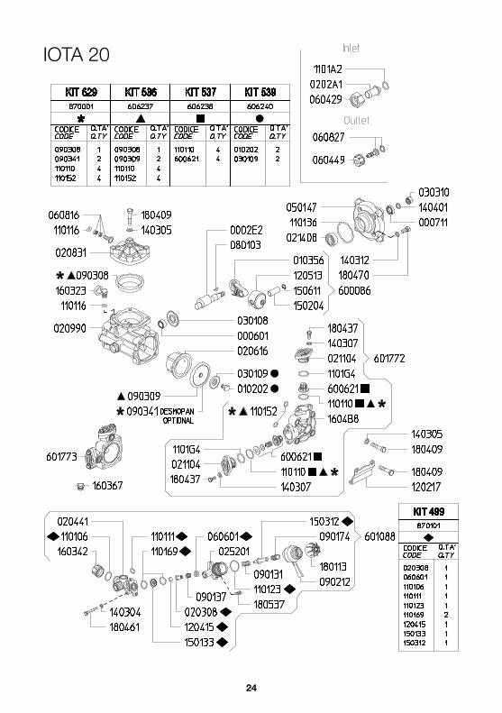
IOTA 20 PUMP Gear Box & Honda GX100 engine
290psi/20bar20 l/min@550rpm6:1 Reduction Gearbox3hp Honda GX100 Engine
Part No . DescriptionGA5023895 3hp GX100 engine5091D9 Udor 6.1 Reduction Gearbox to
suit Honda GXIOTA20 Udor Iota20 pump
24
IOTA 20

25
1
3
6
9
10
2
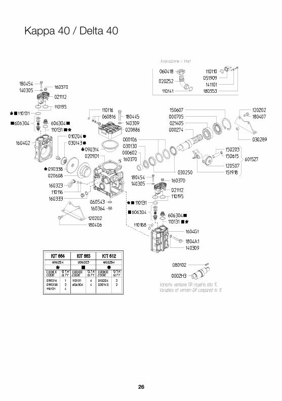
Number Description1 Control valve2 Pump3 Gearbox4 Choke (hidden)5 Pull cord (hidden)6 Fuel cap7 Spark plug (hidden)8 Muffler (hidden)9 On/Off switch 10 Air damper
Kappa 40 / Delta 40 PUMP Gear Box & Honda GX200 engine
580psi/40bar48 l/min@550rpm2 diaphragms6:1 Reduction Gearbox6.5hp Honda GX200 Engine
Part No . DescriptionGA5023085 6.5hp GX200 engine502775 Udor 6.1 Reduction Gearbox
to suit Honda GXKAP40 Udor Kappa40 VA pump
DS3 3 way manual control value
26
Kappa 40 / Delta 40

27

28
General Information and SpecsGeneralThe Pro-Reel hose reel is electrically driven with 12V from the vehicle battery. Up to 150 metres of hose can be fitted and a gunjet provides for even and accurate spray application.Single or multiple units can be linked to an appropriate tank and pump configuration.Chassis:The chassis is an all steel construction, that is fully welded for superior strength. The chassis is shot blasted, primed and then protected by the Goldacres paint process for excellent chemical resistance and durability.Paint Colours:Steel work: G13 Dark Green
Specifications Dimensions See page 11Hose size 10mmHose length 50,100,150 metresPump requirements
Min 20 l/min
Connections 50 Amp Anderson plug
(supplied)Control type Remote
Drive 12V electric
448
671
901
445
352
84 2
39
9
12
D
E
F
C
B
A
321 5
C
D
4 6 7 8
A
B
117.44 Kg
01--
--
-
DEBUR ALL EDGES
DRG. STANDARD/PRACTICE AS 1100
REV
17/03/2015
Drawing Checked:
FINISHED WEIGHT:
Approved
Surface Finish:THIS DRAWING REMAINS THE PROPERTYOF GOLDACRES TRADING PTY LTD AND IS SUBJECT OF COPYRIGHT
UNTOL. DIMENSIONSOPEN DIM ± 0.20ONE DEC. PL. ± 0.10TWO DEC. PL. ± 0.05ANGULAR ± 0.50°
UNLESS OTHERWISE SPECIFIED DIMENSIONS ARE IN MILLIMETRES 24/09/2014
DATE EDITED:
-
ECN NO.NAME/DATECHANGEREV NODavid
James Perks
2015 100m Pro Reel Assembly
GA4904584
1-3 MORANG CRMITCHELL PARK 3352PH: 03 53426399 FAX: 03 53426308
Drawn By:Material:
DO NOT SCALE DRAWING
GOLDACRESTITLE:
DWG NO.
SCALE:1:7
SHEET 3 OF 4
A3
4321
448
671
901
445
352
84
239
9
12
DEF C B A
32
15
CD
46
78
AB
117.44 Kg
01-
-
--
-
DEBUR A
LL EDG
ES
DRG
. STAN
DA
RD/PRA
CTIC
E A
S 1100
REV
17/03/2015
Draw
ing Checked:
FINISHED
WEIG
HT:
Approved
Surface Finish:THIS D
RAW
ING
REMA
INS THE PRO
PERTYO
F GO
LDA
CRES TRA
DIN
G PTY LTD
AN
D IS
SUBJECT O
F CO
PYRIGHT
UNTO
L. DIM
ENSIO
NS
OPEN
DIM
± 0.20O
NE D
EC. PL. ± 0.10
TWO
DEC
. PL. ± 0.05A
NG
ULAR ± 0.50°
UNLESS O
THERWISE SPEC
IFIED D
IMEN
SION
S ARE
IN M
ILLIMETRES
24/09/2014
DA
TE EDITED
:
-
ECN
NO
.N
AM
E/DA
TEC
HAN
GE
REV N
OD
avid
James Perks
2015 100m Pro Reel A
ssembly
GA
4904584
1-3 MO
RAN
G C
RM
ITCHELL PA
RK 3352PH: 03 53426399 FA
X: 03 53426308
Draw
n By:M
aterial:
DO
NO
T SCA
LE DRA
WIN
G
GO
LDA
CRES
TITLE:
DW
G N
O.
SCA
LE:1:7
SHEET 3 OF 4
A3
43
21
446
721
969
239
4
45
85
10.5
9.0
352
446
721
969
239
4
45
85
10.5
9.0
352
446
721
969
239 445
85
10.5
9.0
352
Pro-Reel 50Pro-Reel 100
Pro-Reel 150Pro-Reel Dimentions
29
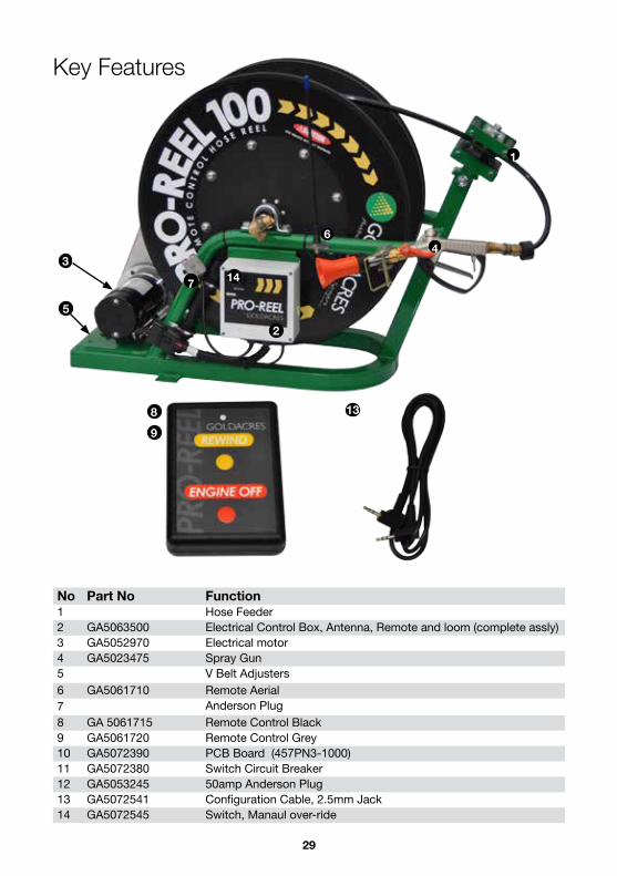
Key Features
No Part No Function1 Hose Feeder2 GA5063500 Electrical Control Box, Antenna, Remote and loom (complete assly)3 GA5052970 Electrical motor4 GA5023475 Spray Gun5 V Belt Adjusters6 GA5061710 Remote Aerial7 Anderson Plug8 GA 5061715 Remote Control Black9 GA5061720 Remote Control Grey10 GA5072390 PCB Board (457PN3-1000) 11 GA5072380 Switch Circuit Breaker 12 GA5053245 50amp Anderson Plug13 GA5072541 Configuration Cable, 2.5mm Jack14 GA5072545 Switch, Manaul over-ride
2
34
1
6
5
147
1389
30
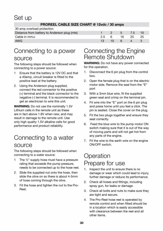
Connecting to a powersourceThe following steps should be followed when connecting to a power source:1 Ensure that the battery is 12V DC and that
a 40amp, circuit breaker is fitted to the positive lead at the battery.
2. Using the Anderson plug supplied, connect the red connector to the positive (+) terminal and the black connector to the negative (-) terminal. It is recommended to get an electrician to wire this unit.
WARNING: Do not use the nominally 1.5V Lithium cells in the remote unit as these are in fact above 1.8V when new, and may result in damage to the remote unit. Use only high quality 1.5V alkaline cells for good performance and product reliability.
Connecting to a watersourceThe following steps should be followed when connecting to a water source:1 The ½” supply hose must have a pressure
rating that exceeds the pump pressure, needs to be connected up to the hose reel.
2. Slide the supplied nut onto the hose, then slide the olive on so there is about 4-5mm of hose coming through the olive.
3. Fit the hose and tighten the nut to the Pro-Reel.
Connecting the Engine Remote ShutdownWARNING: Do not have any power connected for this operation.1. Disconnect the 6 pin plug from the control
box.2. Open the female plug that is on the electric
motor side. Remove the seal from the “E” port
3. With a 3mm blue wire, fit the supplied green seal and crimp on the terminal pin.
4. Fit wire into the “E” port on the 6 pin plug and press home until you feel a click. The pin is seated. Close the cover on the plug.
5. Fit the two plugs together and ensure they seat correctly.
6. Feed the blue wire to the pump motor ON switch making sure that it is out of the way of moving parts and will not get hot from any parts of the engine.
7. Fit the wire to the earth wire on the engine ON/OFF switch.
OperationPrepare for use1. Inspect the unit to ensure there is no
damage or wear which could lead to injury, further damage or reduce its performance.
2. Check all hoses and fittings, including spray gun, for leaks or damage.
3. Check all bolts and nuts to make sure they are tight and secure.
4. The Pro-Reel hose reel is operated by remote control and when fitted should be in a location which is easily accessible with clearance between the reel and all other items.
PROREEL CABLE SIZE CHART @ 12vdc / 30 amps30 amp overload protectionDistance from battery to Anderson plug (mts) 1 2 5 7.5 10Cable in mmx2 2.5 6 16 25 25AWG 13 10 6 4 3
Set up

31
InstructionsCAUTION: Keep hands, feet,hair and clothing away from all moving parts to prevent injury.NOTE: Hose will un-wind with a small amount of restriction when pulled out by handOperation1. While connected to a power source, the
unit is always powered.2. Remove the linch pin and check the spray
gun.3. Test the remote and manual rewind
functions. The manual “REWIND” button is located on the control box.
4. Unwind the hose (taking care to not over-run the hose)
5. The hose can then be wound in by pressing the “REWIND” button on the remote control.
6. If the reel stops turning due to a hose jam DO NOT continue to push the button or damage may occur. Clear the cause of the jam prior to further operation. If the remote does not work after the jam, the control box overload may need to be reset. Press to reset.
7. When finished, rinse the line out with fresh water.
8. Retract all the hose and remount the spray gun.
9. When complete, disconnect the power at the anderson plug.
Current overload reset button

32
Goldacres Pro-Reel® Single Reel Controller ConfigurationThis manual provides instructions for the configuration of the Goldacres Pro-Reel® wireless controller system.
Figure 1: From left to right, Pro-Reel® Control Box, the configuration cable and the hand-held remote unit.
Figure 2: On the left is an inside view of the Pro-Reel® Control Box showing the parts relevant to setup. On the right is a view of the hand-held remote unit underside with the battery cover and battery pack removed, exposing the configuration socket.

33
Supplying Power to the Remote Unit and the Pro-Reel® Control Box.Refer to figure 2 on page 1 for information on the locations of the various parts.CAUTION: Ensure that battery polarity is correct when inserting batteries into the remote unit batterycompartment.WARNING: Do NOT use the nominally 1.5V Lithium cells in the remote unit as these are in fact above1.8V when new and may result in damage to the remote unit. Use only high quality 1.5V alkaline cells forgood performance and product reliability.For the remote unit, ensure that a suitable pair of 1.5V cells are inserted correctly into the unit. The battery coveris on the rear of the unit at the base. Two size ‘AAA’ cells will be required. Spring contacts in the battery holderalways connect to the negative ends of the cells. Also under the battery cover can be found the configurationsocket (see figure 2 on page 1) which is a 2.5mm socket. This is used to connect the remote unit and the controlbox together with the supplied configuration cable to enable programming of remote unit buttons to control boxrelays. The battery holder must be removed in order to access the configuration socket of the remote unit, but thebatteries should be left in the holder to ensure that the remote unit is still powered.The Pro-Reel® control box should already be suitably configured with 12V DC vehicle battery power.
Pro-Reel® Control Box Configuration.Configuration of the system is required if replacing a damaged or lost remote (hand held transmitter) unit, since
each transmitter and receiver are paired using unique identifier codes.2.1 Configuring a Remote Unit to control a
Control Box’s relays . In the event that a remote unit must
be replaced or a new one added to an existing configuration, the following steps will enable a new remote unit to be used with an existing control box. The location of relevant parts can be identified using figure 2 on page 1.
CAUTION: Do not touch any component in the control box except those parts referred to in the following procedure.
1. Check that the DIP switch (SW1 in the control box) is set as follows:
Figure 3: DIP Switch (SW1) setting. Note that all switches are in the OFF position except switch 6.
2. Connect the configuration cable between the remote unit and the control box via the configuration sockets. If done successfully, the red light of each unit will light up continuously. If both lights do not ensuring that neither light is lit and then reconnect the cable. (If, after several attempts to establish the configuration connection, the lights do not both remain lit, then consult the troubleshooting section, section 3, of this manual.)
3. Once the red lights of both the remote unit and the control box remain lit while the configuration cable is connected, press and hold push-button switch, SW2, in the control box until the control box’s red light turns off, then release the push-button switch. The control box’s red light should remain off but the remote unit’s red light should still be on.
4. On the remote unit, depress the Rewind button. The light on the remote unit should turn off and the light in the control box should very briefly turn on and then

34
immediately off again.5. Now depress the Engine Off button on
the remote unit. The light on the remote unit will turn back on and the light in the control box should also switch on and remain on. This indicates that the configuration is complete.
6. Disconnect the configuration cable and test the system by pressing each of the two remote unit buttons in succession to observe whether or not they perform as required.
This completes the setup and test of a hand-held remote unit with a Pro-Reel® control box. If there are problemswith operation of the system, the control box can be restored to factory settings as follows:
Restoring a Control Box to factory default settings.Do not connect the configuration cable since this operation is done to the control box alone.1. Press and hold down the control box
push-button switch, SW2, for at least 12 seconds. Time this by counting slowly to 12, during which time the red light will switch on and off various times and for various durations. When the required time has elapsed, the light will blink on and off continuously at a fast rate (flashing about twice per second). This means that 12 seconds has elapsed.
2. Release the push-button switch. The control box’s factory settings have now been fully restored.
3. Perform the configuration process again, as described in section 2.1, if required.
The control box factory restore process will always restore settings back to their factory defaults. If any settingshave been altered for an alternative mode of operation, these will have to be configured again.
Troubleshooting.The following list of items may be used to aid in fault finding if the control box fails to respond to remote unit transmissions. Use this when the control box is opened for configuration of a new or replacement remote unit if the equipment fails to perform correctly upon configuration.NOTE: Do not attempt repairs to the control box internal circuitry or associated wiring looms, connectors and external associated equipment. This list is only intended as a basic guide to resolve any minor issues or to simply locate potentially major issues that may result from wear of the equipment. Refer all servicing to the product supplier.CAUTION: Do not make physical contact with any of the components in the control box except to connect the configuration cable to the configuration socket, to set the DIP switch (SW1) as described in section 2.1 (if it has been altered) and to press the push-button switch (SW2) as described in section 2.1. Contamination of circuitry or electrostatic discharge into the circuit may result in permanent damage to the control box.1 Check control box power as described in
section 1. Ensure that adequate vehicle battery power is available to the Pro-Reel® control box and that it is correctly connected. The system is designed for 12V DC automotive power supplies.
2. Press and release the Pro-Reel® control box current overload reset button (on the left side of the control box exterior) in case an overload has occurred. If the unit now works, it is advisable to inspect the system to discover, if possible, what caused the overload and rectify the problem.
3. Check that the hand-held remote unit batteries are correctly oriented and that they are serviceable. Replace them if uncertain about their age. Never mix old and new batteries or batteries of different types. When replacing batteries, always replace both with a pair of the same type of batteries. Mixing batteries can result in damage to the remote unit if either battery leaks. Refer to section 1 regarding the correct selection of battery types.

35
4. Perform the configuration procedure again as described in section 2.1 but do a factory restore of the control box first, if not already done, as described in section 2.2. Ensure that the configuration cable that was supplied with the unit is used. Disconnect the configuration cable when done.
5. When pressing the remote unit buttons to test operation, check that the remote unit red light lights up while a button is being pressed. If not then either the remote unit has not been correctly configured or the battery voltage is not correct or it is a faulty unit.
6. If the remote unit light lights up when pressing a button, listen for relay clicking sounds inside the Pro-Reel® control box. Each remote unit button must control a relay in the control box and when they are operating the relays can clearly be heard. This ensures that remote control communications is working.
7. Visually inspect the wiring looms and connectors attached to the Pro-Reel® control box and associated external devices for correct fit and any possible wear or damage to wires, wire insulation or connector housing. Inspect also for signs of water damage or corrosion. Damaged connectors or wiring looms should be immediately repaired (refer to your product supplier) as they pose a short circuit risk to the vehicle’s electrical system. Never operate a unit with damaged wiring or damaged, loose or poorly fitting connectors as this poses a risk to both the equipment and the vehicle’s electrical system.
8. Check the external antenna connection and inspect for any damage to the antenna cable or a damaged or loose connector at the exterior of the control box. Also check that the control box antenna connector is correctly attached to the control box SMA connector inside the control box when opened. The SMA connector is the gold coloured connector connecting the antenna cable to the control box receiver board (see figure 2 on page 1). The connector should not be loose but
do not tighten further if it is not loose. Loss of received signal strength that may result from damaged or poorly connected antenna cables or connectors will typically become a problem when the remote unit is at a distance from the control box. CAUTION: Do not make physical contact with any part of the control box printed circuit board or components except to check the antenna connector.
9. Visually inspect the interior of the Pro-Reel® control box while it is open for any loose wires or connections or any loose foreign object that may result in short circuiting of exposed electrical conductors or components. Ensure that all connections are secure and that the control box is free of foreign objects before refitting the control box cover.
If the problem cannot be determined, then refer to your product supplier for assistance.
36
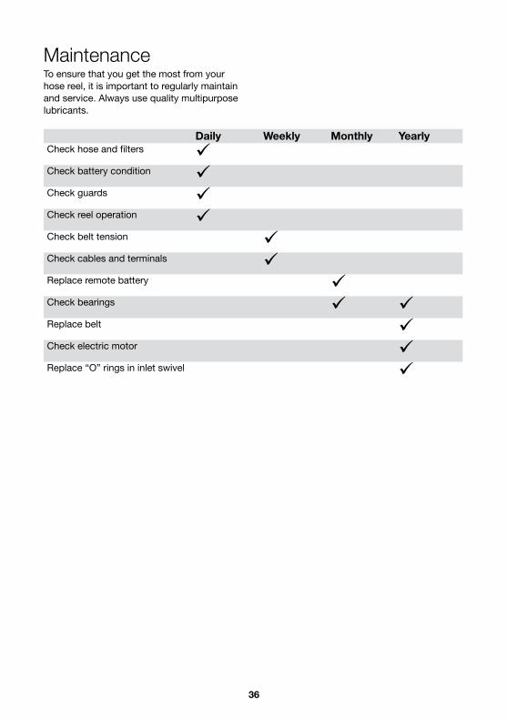
MaintenanceTo ensure that you get the most from your hose reel, it is important to regularly maintain and service. Always use quality multipurpose lubricants.
Daily Weekly Monthly YearlyCheck hose and filters Check battery condition Check guards Check reel operation Check belt tension Check cables and terminals Replace remote battery Check bearings Replace belt Check electric motor Replace “O” rings in inlet swivel

37
Technical DataSupply voltage: 11.0 – 28 VDC, 10.0 – 28 VAC. Can use Elsema DC or AC power supply,12PP1000 or 24PP. 433.920 (Standard),433.664, 433.408, 433.152 MHz.433 MHz Frequencies:Relay Output: Two relays rated at 8 amps /240V each.Recommended Antenna:ANT433 series (433MHz Series)
TroubleshootingThe troubleshooting information is provided as a reference when your reel is not functioning correctly.To ensure that you receive the best possible service, it is recommended that you exhaust all applicable troubleshooting solutions shown prior to calling your dealer, or Goldacres, for service advice.
Problem Possible Cause Possible Remedy
Reel does not wind
Hose jam Unwind to clear jam
Overload fuse tripped Press the Overload reset button
Fuse blown Check/replace fuse
Loose connections Check battery and connections
Manual Rewind switch faulty Check manual switch
Loose/broken drive belt Adjust or replace drive belt
Seized bearings on reel shaft Replace bearings
Remote does not operate at distance
Damaged aerial or lead Repair or replace aerial or lead
Flat Battery Replace battery
Remote not calibrated with the receiver
Recalibration required Refer to Calibration instructions
Faulty transmitter/receiver
Replace batteries
Replace Remote
Refer to Calibration instructions
Battery replaced in remote Batteries are not correctly fitted

38
Item No Part No Description Qty1 GA4660585 Frame, 2015 100m Pro Reel
GA4660510 Frame, 2014 150m Pro Reel2 GA4914000 Hose Reel, 100m Assembly 13 GA5061735 Housing, to suit SA205-14 Bearing 24 GA5061740 Bearing SA205-14 25 GA5000115 Washer flat SS 10mm 46 GA5011175 Bolt M10 x 60 ZP GR8.8 47 GA5000141 Nut M10 Nyloc 48 GA4508615 Control Box Mounting Plate 19 GA4400155 Plate, Bearing and Antenna Mount, 100-200m Pro Reel 110 GA5048150 ½" BSPT - ½" BSPT male, 90 Degree elbow 111 GA5023476 ½" BSPM - ½" BSPF Swivel Connection 112 GA4400160 Plate, Bearing Mount, Pro Reel 1
13 GA5023170 External compression Fitting, include olive, ½” T x ½” BSPF C073 1
8
6
5
9
3
7
2
4
13
11
10
1
12
3
7
4
5
6
mount/QTY.
1 GA4660585 Frame, Pro Reel 100 m Assembly 1
2 GA4914000 Hose Reel, 100m Assembly 13 GA5061735 Housing to suit SA205-14 Bearing 24 GA5061740 Bearing SA205-14 25 GA5000115 Washer flat SS 10mm 46 GA5011175 Bolt M10 x 60 ZP GR8.8 47 GA5000141 M10 Nyloc Nut 48 GA4508615 Control Box Mounting Plate 1
9 GA4400155 Plate, Bearing and Antenna Mount, 100-200m Pro Reel 1
10 GA5048150 1/2" BSPT - 1/2" BSPT male 90o elbow 1
11 GA5023476 1/2"BSPM. 1/2"BSPF. SWIVEL CONNECTION 1
12 GA4400160 Plate, Bearing Mount, Pro Reel 1
13 GA5023170 External compression Fitting inc olive 1/2Tx1/2BSPF C073 1
D
E
F
C
B
A
321 5
C
D
4 6 7 8
A
B
110.10 Kg
01--
--
-
DEBUR ALL EDGES
DRG. STANDARD/PRACTICE AS 1100
REV
17/08/2015
Drawing Checked:
FINISHED WEIGHT:
Approved
Surface Finish:THIS DRAWING REMAINS THE PROPERTYOF GOLDACRES TRADING PTY LTD AND IS SUBJECT OF COPYRIGHT
UNTOL. DIMENSIONSOPEN DIM ± 0.20ONE DEC. PL. ± 0.10TWO DEC. PL. ± 0.05ANGULAR ± 0.50°
UNLESS OTHERWISE SPECIFIED DIMENSIONS ARE IN MILLIMETRES 24/09/2014
DATE EDITED:
-
ECN NO.NAME/DATECHANGEREV NODavid
James Perks
2015 100m Pro Reel Assembly
GA4904584
1-3 MORANG CRMITCHELL PARK 3352PH: 03 53426399 FAX: 03 53426308
Drawn By:Material:
DO NOT SCALE DRAWING
GOLDACRESTITLE:
DWG NO.
SCALE:1:5
SHEET 1 OF 5
A3
4321
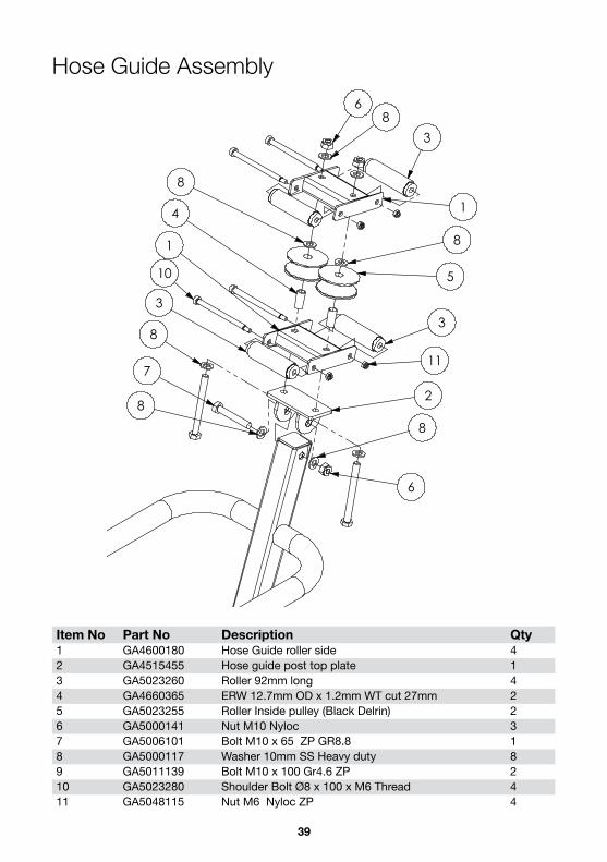
Pro-Reel AssemblyThere is mounting holes drilled in the frame of the Pro-Reel to help in securing the unit to a customers setup.
39
Item No Part No Description Qty1 GA4600180 Hose Guide roller side 42 GA4515455 Hose guide post top plate 13 GA5023260 Roller 92mm long 44 GA4660365 ERW 12.7mm OD x 1.2mm WT cut 27mm 25 GA5023255 Roller Inside pulley (Black Delrin) 26 GA5000141 Nut M10 Nyloc 37 GA5006101 Bolt M10 x 65 ZP GR8.8 18 GA5000117 Washer 10mm SS Heavy duty 89 GA5011139 Bolt M10 x 100 Gr4.6 ZP 210 GA5023280 Shoulder Bolt Ø8 x 100 x M6 Thread 411 GA5048115 Nut M6 Nyloc ZP 4
Hose Guide Assembly
6
88
7
10
3
2
11
3
4
8
8
3
6
8
1
5
1
8
ITEM NO.
PART NUMBER DESCRIPTION QTY.
1 GA4600180 Hose Guide roller side 4
2 GA4515455 Hose guide post top plate 1
3 GA5023260 Roller 92mm long 4
4 GA4660365 ERW 12.7mm OD x 1.2mm WT cut 27mm 2
5 GA5023255 Roller Inside pulley (Black Delrin) 2
6 GA5000141 M10 Nyloc Nut 3
7 GA5006101 Bolt M10 x 65 ZP GR8.8 1
8 GA5000117 Washer 10mm SS Heavy duty 8
9 GA5011139 Bolt M10 x 100 Gr4.6 ZP 2
10 GA5023280 Shoulder Bolt Ø8 x 100 x M6 Thread 4
11 GA5048115 Nut M6 Nyloc ZP 4
14 GA5072120 Pulley, PCD 1 1/2", 16mm bore, 5mm keyway, Pro Reel 1
15 GA5072120-Grub - 1
D
E
F
C
B
A
321 5
C
D
4 6 7 8
A
B
28.36 Kg
01--
--
-
DEBUR ALL EDGES
DRG. STANDARD/PRACTICE AS 1100
REV
17/08/2015
Drawing Checked:
FINISHED WEIGHT:
Approved
Surface Finish:THIS DRAWING REMAINS THE PROPERTYOF GOLDACRES TRADING PTY LTD AND IS SUBJECT OF COPYRIGHT
UNTOL. DIMENSIONSOPEN DIM ± 0.20ONE DEC. PL. ± 0.10TWO DEC. PL. ± 0.05ANGULAR ± 0.50°
UNLESS OTHERWISE SPECIFIED DIMENSIONS ARE IN MILLIMETRES 24/09/2014
DATE EDITED:
-
ECN NO.NAME/DATECHANGEREV NODavid
James Perks
2015 100m Pro Reel Assembly
GA4904584
1-3 MORANG CRMITCHELL PARK 3352PH: 03 53426399 FAX: 03 53426308
Drawn By:Material:
DO NOT SCALE DRAWING
GOLDACRESTITLE:
DWG NO.
SCALE:1:5
SHEET 4 OF 5
A3
4321

40
Item No Part No Description Qty1 GA5063500 Auto wind control box & antenna 12 GA4534635 Bracket Nozzle suit small booms 13 GA5013003 Pipe linch pin, 8 OD x 60 long 14 GA5002237 Pan Head Screw M3 x 35mm 45 GA5049465 Nut M3 Nyloc SS 46 GA5004085 Bolt M8 x 20 17 GA5003643 Washer 8mm HD SS 18 GA5004050 BHCS M6 x 16mm SS 29 GA5004437 Washer 6mm SS 410 GA5048115 Nut M6 Nyloc ZP 211 GA5004919 Washer 8mm Spring SS 112 Antenna Mount Plate 1
Control Box, Antenna & Gun Mount
12 9 109
8
2
3
7116
5
4
1
ITEM NO. PART NUMBER DESCRIPTION Parts Book - Controlbox Gun/QTY.
1 GA5063500 Auto wind control box & antenna 12 GA4534635 Bracket Nozzle suit small booms 13 GA5013003 Pipe linch pin, 8 OD x 60 long 14 GA5002237 Pan Head Screw M3 x 35mm 45 GA5049465 M3 Nyloc nut SS 46 GA5004085 M8x20 bolt 17 GA5003643 Washer 8mm HD SS 18 GA5004050 M6x16mm Button head soc SS 29 GA5004437 M6 SS Washer 4
10 GA5048115 Nut M6 Nyloc ZP 211 GA5004919 M8 Spring washer SS 1
12 Antenna Mount plate Antenna Mount Plate 1
D
E
F
C
B
A
321 5
C
D
4 6 7 8
A
B
13.76 Kg
01--
--
-
DEBUR ALL EDGES
DRG. STANDARD/PRACTICE AS 1100
REV
18/08/2015
Drawing Checked:
FINISHED WEIGHT:
Approved
Surface Finish:THIS DRAWING REMAINS THE PROPERTYOF GOLDACRES TRADING PTY LTD AND IS SUBJECT OF COPYRIGHT
UNTOL. DIMENSIONSOPEN DIM ± 0.20ONE DEC. PL. ± 0.10TWO DEC. PL. ± 0.05ANGULAR ± 0.50°
UNLESS OTHERWISE SPECIFIED DIMENSIONS ARE IN MILLIMETRES 24/09/2014
DATE EDITED:
-
ECN NO.NAME/DATECHANGEREV NODavid
James Perks
2015 100m Pro Reel Assembly
GA4904584
1-3 MORANG CRMITCHELL PARK 3352PH: 03 53426399 FAX: 03 53426308
Drawn By:Material:
DO NOT SCALE DRAWING
GOLDACRESTITLE:
DWG NO.
SCALE:1:5
SHEET 6 OF 6
A3
4321
41
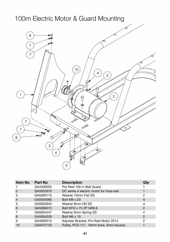
Item No Part No Description Qty1 GA4400035 Pro Reel 100 m Belt Guard 12 GA5052970 DC series 4 electric motor for hose reel 13 GA5000115 Washer 10mm Flat SS 24 GA5004085 Bolt M8 x 20 45 GA5003643 Washer 8mm HD SS 46 GA5006073 Bolt M10 x 75 ZP GR8.8 27 GA5004447 Washer 6mm Spring SS 48 GA5004029 Bolt M6 x 10 29 GA4660515 Adjuster Bracket, Pro Reel Motor 2014 210 GA5072120 Pulley, PCD 1½", 16mm bore, 5mm keyway 1
100m Electric Motor & Guard Mounting
21
9
6
3
8
7
7
8
7
7
45
10
12
13 14
11
ITEM NO. PART NUMBER DESCRIPTION Motor, Guard and Swivel Feeder/QTY.
1 GA4400035 Pro Reel 100 m Belt Guard 1
2 GA5052970 DC series 4 electric motor for hose reel 1
3 GA5000115 Washer flat SS 10mm 2
4 GA5004085 M8x20 bolt 4
5 GA5003643 Washer 8mm HD SS 4
6 GA5006073 Bolt M10 x 75 ZP GR8.8 2
7 GA5004447 M6 Spring washer SS 4
8 GA5004029 M6x10 bolt 2
9 GA4660515 Adjuster Bracket, Pro Reel Motor 2014 2
10 GA5072120Pulley, PCD 1 1/2", 16mm bore, 5mm keyway, Pro
Reel1
11 GA4906995 Hose Feeder Assembly, 2014 Pro Reel 1
12 GA5011163 Bolt M10 x 70 ZP GR8.8 1
13 GA5000117 Washer 10mm SS Heavy duty 2
14 GA5000141 M10 Nyloc Nut 1
D
E
F
C
B
A
321 5
C
D
4 6 7 8
A
B
28.36 Kg
01--
--
-
DEBUR ALL EDGES
DRG. STANDARD/PRACTICE AS 1100
REV
17/08/2015
Drawing Checked:
FINISHED WEIGHT:
Approved
Surface Finish:THIS DRAWING REMAINS THE PROPERTYOF GOLDACRES TRADING PTY LTD AND IS SUBJECT OF COPYRIGHT
UNTOL. DIMENSIONSOPEN DIM ± 0.20ONE DEC. PL. ± 0.10TWO DEC. PL. ± 0.05ANGULAR ± 0.50°
UNLESS OTHERWISE SPECIFIED DIMENSIONS ARE IN MILLIMETRES 24/09/2014
DATE EDITED:
-
ECN NO.NAME/DATECHANGEREV NODavid
James Perks
2015 100m Pro Reel Assembly
GA4904584
1-3 MORANG CRMITCHELL PARK 3352PH: 03 53426399 FAX: 03 53426308
Drawn By:Material:
DO NOT SCALE DRAWING
GOLDACRESTITLE:
DWG NO.
SCALE:1:5
SHEET 2 OF 5
A3
4321

42
Item No Part No Description Qty1 GA4600085 Pro Reel, Shaft Assembly 12 GA4583425 Side Plate, Hose Reel Remote Control 33 GA5048120 BHCS M10 x 30 84 GA0500007 Grub Screw, ¼" UNF 25 GA5069975 BHCS M5 x 16mm SS 126 GA5003983 Washer 5mm SS 127 GA5000115 Washer 10mm Flat SS 328 GA0500005 BHCS M10 x 70 89 GA4583455 Flange, Bolt on, suit hose reel shaft 210 GA4583125 Spacer Hose Reel Remote Control Long 811 GA5071975 V Belt Plate, Hose Reel Remote Control 212 GA5000137 Washer 10mm Spring SS 1613 GA5023610 Brass Elbow ½” x ½” Male Thread 1
14 GA5023170 External compression Fitting, include olive ½” T x ½” BSPF C073 1
15 GA5023495 Pro Reel ½” Nylon Hose 100m ( not shown) 1
Hose Reel 100m
2
2
11
11
3
5
10
7
9
1
9
56
4
7
4
67
87
12
12 14
13
ITEM NO. PART NUMBER DESCRIPTION Parts
books/QTY.1 GA4600085 Pro Reel, Shaft Assembly 1
2 GA4583425 Side Plate, Hose Reel Remote Control 3
3 GA5048120 M10x30 BHCS 84 GA0500007 Grub Screw, 1/4" UNF 25 GA5069975 BHCS M5 x 16mm SS 126 GA5003983 M5 washer ss 127 GA5000115 Washer flat SS 10mm 328 GA0500005 M10x70 BHCS 89 GA4583455 Flange, Bolt on, suit hose reel shaft 2
10 GA4583125 Spacer Hose Reel Remote Control Long 8
11 GA5071975 V Belt Plate, Hose Reel Remote Control 2
12 GA5000137 Washer 10mm Spring S/S 1613 GA5023610 Brass Elbow 1/2 x 1/2 Male Thread 1
14 GA5023170 External compression Fitting inc olive 1/2Tx1/2BSPF C073 1
43
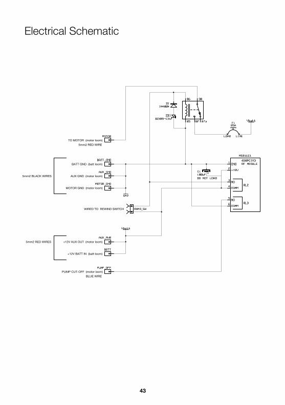
Electrical Schematic
+12V AUX OUT (motor loom)
+12V BATT IN (batt loom)
TO MOTOR (motor loom)
BATT GND (batt loom)
AUX GND (motor loom)
MOTOR GND (motor loom)
PUMP CUT-OFF (motor loom)
5mm2 RED WIRES
5mm2 BLACK WIRES
BLUE WIRE
5mm2 RED WIRE
WIRED TO REWIND SWITCH

44
Safety DecalsUnderstanding safety decals and their purpose assists in the safe operation of your sprayer. Safety decals are there for your protection and it is the responsibility of the owner operator to replace damaged and/or missing safety decals. Regularly review safety decals with operators. It is very important to ensure that all new machine components and replacement parts include current hazard identification decals. Replacement safety decals can be ordered from all Goldacres dealers.
Item No Part No Description1 GA8700006 Decal, Pro-Reel Autowind, Remote Control2 GA5015991 Sticker KEEP HANDS CLEAR3 GA5064610 Decal 50 mt Pro Reel Decal4 GA5064615 Decal 100 mt Pro Reel Decal kit5 GA5064620 Decal 150 mt Pro Reel Decal Kit
1 2 3
4 5

45
GA8700425 Pro-Reel 200L Tank Decal
GA8700426 Pro-Reel 300L Tank Decal
GA8700427 Pro-Reel 400L Tank Decal
GA8700428 Pro-Reel 600L Tank Decal

46
GA8700429 Pro-Reel 800L Tank Decal
GA8700441 Pro-Reel 1000L Tank Decal

47
TroubleshootingThe troubleshooting information is provided as a reference when your sprayer is not functioning correctly.
To ensure that you receive the best possible service, it is recommended that you exhaust all applicable troubleshooting solutions shown prior to calling your dealer, or Goldacres, for service advice.
Problem Common Causes Common Solution
Pressure and flow rate are too low
Excessive bypass on pressure manifold
Check the pressure relief valve setting on pressure manifold.
Supply to pump is restricted
Close the ball valve labelled bypass, if the pressure increases on the pump gauge there is a problem with the control valveMeasure the flow per minute coming out of one nozzle and check the nozzle chart for the corresponding flow.Suction filter may be blockedCheck tank sump and suction line blockagesCheck suction line for air leaksCheck pump speedCheck oil for colour change. If the oil appears milky, a diaphragm will be damaged and needs to be replaced.Check valves in pump.
Pressure and flow rate are too high
Bypass line is restricted or blocked..
Check for restriction in bypass line.Check pump speed is not too fast.
The pressure on my gauge is higher than the nozzle flow indicates
Blocked filters of nozzlesCheck and clean all pressure and nozzle filtersFlow loss due to resistance in
lines, valves and filters.
The flow rate is correct but my pressure is too low or high.
Nozzles Check nozzle chart for correct nozzle size.
Pressure fluctuation
Air leak on suction side of pump Check suction pump for air leaks
Incorrect pump speed Adjust pump speed so it is between 400 -540rpm
Faulty pump valves Replace pump valves
Pump pressure pulsating
Air accumulator pressure is incorrect Reset the pressure in air accumulator
Air accumulator diaphragm has a leak Replace air accumulator diaphragm
Incorrect pump speed Adjust pump speed so it is between 400 - 540rpm
Air leak on suction side of pump Check pump suction for air leaks
Diaphragm Pump
48
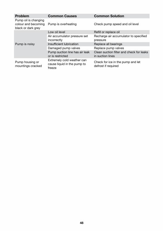
Problem Common Causes Common SolutionPump oil is changing colour and becoming black or dark grey
Pump is overheating Check pump speed and oil level
Pump is noisy
Low oil level Refill or replace oilAir accumulator pressure set incorrectly
Recharge air accumulator to specified pressure
Insufficient lubrication Replace all bearingsDamaged pump valves Replace pump valvesPump suction line has air leak or is restricted
Clean suction filter and check for leaks in suction lines
Pump housing or mountings cracked
Extremely cold weather can cause liquid in the pump to freeze
Check for ice in the pump and let defrost if required

49

50
l/min (indicative cone nozzle flow rates)CODE �∕
(mm)5 bar 10 bar 15 bar 25 bar 35 bar 40 bar
GA2000108 1.5 3.28 2.99 4.64 4.22 5.69 5.17 7.34 6.68 8.69 7.90 9.29 8.45GA2000109 2.0 5.67 4.78 8.02 6.75 9.83 8.27 12.69 10.68 15.01 12.64 16.05 13.51GA0100018 2.5 8.00 6.34 11.31 8.97 13.85 10.98 17.88 14.18 21.16 16.78 22.62 17.94GA5071875 3.0 10.08 7.50 14.26 10.61 17.46 12.99 22.54 16.77 26.67 19.85 28.52 21.22GA5023477 3.5 12.33 8.15 17.44 11.53 21.36 14.12 27.58 18.23 32.63 21.57 34.88 23.06
Turbo 400 spray gun.The Turbo 400 spray gun is ideally suited to
the pro reel range as it can handle up to 700 psi pressure and a 70 l/min flow rate. It is
available with a wide range of nozzles to suit many spraying applications.
The standard nozzle supplied with the Turbo 400 spray gun is a 2.5mm, please check chart as shown below for other nozzle options.
The lever on the left hand side of the gun will adjust the flow from a wide fan with the lever fully down to a pencil flow with the lever fully up, this can be adjusted to gain greater spraying distance when the target is far away.A trigger lock can be used for continuous spraying.
The gun features a “ Turbo” Atomiser to produce an extremely fine, soft impact spray ideal for spraying in greenhouses, simply slide the end nozzle should back or forward to alter the spray effect.

51
SafetyGeneralThe following pages outline important safety information. At Goldacres safety is a high priority. These safety and warning instructions MUST be followed to ensure the safe operation of your Goldacres equipment.Explanation of key terms used in this operator’s manual are:DANGER - You could be killed or seriously hurt if you don’t follow instructionsWARNING - You can be seriously hurt if you don’t follow instructionsCAUTION - You can be hurt if you don’t follow instructionsNOTE - Is used to notify people of installation, operation or maintenance information that is important but not hazard related.
The OperatorAll operators of this equipment should be adequately trained in the safe operation of this equipment. It is important that all operator’s have read and fully understand the operators manual prior to using this equipment.All new operators should be trained in an area without bystanders or obstructions and become familiar with the sprayer prior to operation.
Safety PrecautionsDANGER• Puncture Hazard. Always keep body, head
and hands away from sharp edgesWARNINGS• Any unauthorised modifications to this
equipment may affect its function and create a serious safety risk.
• Never attempt to clean parts or nozzles, by blowing with mouth.
• Never attempt to siphon chemicals, or substances, by sucking.
• It is imperative that the vehicle manufacturer’s specifications be checked and all instructions for use when
transporting, or towing, be adhered to at all times.
• Do not use the pump in a gaseous or hazardous environment or near combustible material.
• Do not use the pump in an enclosed area, engine exhaust could build up and cause asphyxiation.
• Care should be taken when transferring liquid into the tank to ensure that the gross weight of the equipment does not exceed the safe working load for the operator.
• Water weighs 1kg per litre, however conversion factors must be used when spraying liquids that are heavier or lighter than water. Example: liquid urea has a density of 1.28 kg/L and will therefore be significantly heavier than water if the tank is filled completely.
• Regularly check the pump mounting bolts. (The pump will always vibrate to some degree when operating, and this may work the bolts loose.)
• Suitable care should be taken when driving with the equipment attached to the vehicle. Consideration should be given to both the carrying capacity of the vehicle and the gradient of the terrain when determining the speed at which the vehicle can be driven safely.
• Ensure that the maximum speed of the vehicle, when loaded, is within the vehicle manufacturers limitations.
• Ensure equipment is securely fastened, or attached, to the vehicle at all times.
• Keep clear of overhead obstructions - especially powerlines as contact can be fatal.
• Never work under a raised boom unless properly supported and secure.
• Do not use access steps or ladders on this equipment unless it is safely supported on solid blocks or by vehicle attachment. If unsupported, the equipment can become unstable and may become likely to tip
Pinch Points • Always be alert whenever you place your
fingers, hands, toes, or feet between any objects

52
• Loose clothing, jewelry, and hair can be pulled into pinch points. Accordingly, wear snug clothing, remove jewelry, and tie long hair back or secure under a cap before working in the vicinity of pinch point hazards
• Watch your hands and fingers when opening or closing boom sections
Fluids Under Pressure Fluids escaping from high pressure lines can cause serious injury to skin. Hydraulic oil can easily penetrate human skin. This hazard can be avoided by relieving the pressure in the system.Do not disconnect any hoses, nozzles or filters while equipment is operating. Disconnecting these components while under pressure may result in uncontrolled fluid discharge which may be hazardous. When the repair is complete ensure that all fittings and lines are secured before re-applying pressure.Entanglement in Rotating Drive Lines Rotating drives can cause serious injury or even death when entanglement occurs. Keep hands, feet, hair and clothing away from all moving parts to prevent injury. Never operate this machine with covers, shrouds, or guards removed. To reduce the risk of entanglement, ensure that the appropriate PPE is worn and ensure that all other clothing is not loose fitting.Air Borne ParticlesAlways stand well clear of equipment during operation. Any spray drift is dangerous and may be hazardous to humans. When heating and welding components, ensure that all paint and other such materials are removed. Often hazardous air borne particles and fumes are generated from welding and heating.When sanding the machine, work in a well ventilated area and wear an approved respirator. If a solvent is used to remove paint and other substances, wash the area with soap and water to neutralise the work area.Do Not Carry PassengersDo not stand or carry passengers on the steps or platform when the equipment is in motion or when the booms are being folded or unfolded.
CAUTIONS• A supply of fresh water should be with the
equipment at all times.• Standard polyethylene tanks are not
designed for use with diesel fuel or any flammable liquid.
• Do not use this machine in ambient temperatures exceeding 40 degrees Celsius.
• Each individual boom section has a maximum delivery of 35 litres per minute with clean filters fitted.
• The maximum combined flow of all boom sections is limited to 140 litres per minute, or 50% of the pump flow whichever is the lesser amount, with clean filters.
• Do not exceed the maximum spraying pressure of 8 Bar.
• Ensure that all bolts are tightened and secured before operation.
• Where fitted, care should be taken to never overfill the diaphragm pump with oil or operate at speeds exceeding 540 rpm.
• Where fitted, always ensure that the boom is securely supported when travelling
• Do not use access steps or ladders on this equipment unless it is safely supported.
NOTES• Always read and understand the
operator’s manual prior to operation of this equipment.
• It is the responsibility of the operator to ensure that there are no decals missing from the equipment and that any damaged or missing decals are replaced prior to operation.
• Goldacres equipment ordered or operated, outside the guideline limitations may not be warranted by Goldacres for successful performance. Operators working outside these limitations do so at their own risk, unless specific advice has been sought from and provided by Goldacres in writing.
• Inspect the equipment thoroughly for damage and wear before operation.
• Do not operate the equipment while under the influence of any drugs, alcohol or if excessively tired.
53
• Make sure that the equipment complies with all relevant road regulations when transporting.
• Not all Goldacres fire fighting units/water carts are legal for road use. The Goldacres Road pack includes changes to the trailer specification for road use. The addition of lights to a trailer that has been built for off road use only may not be sufficient to satisfy requirements for road use.
• After reading the operator’s manual if there is any thing that you do not understand please contact your Goldacres dealer or Goldacres.
Fluids under pressureDo not disconnect any hoses, nozzles or filters while equipment is operating. Disconnecting these components while under pressure may result in uncontrolled fluid discharge which may be hazardous. When the repair is complete ensure that all fittings and lines are secured beforere-applying pressure. Slippery Surfaces• The surface of the platform has raised
portions to stop slipping. • The platform surface needs to be kept
clean of mud and other material to help stop slipping.
Main Tank• Danger - Confined space do not enter.• Do not enter the tank for any purpose.
Safe Use of ChemicalsThe safe use of Ag chemicals with this equipment is the responsibility of the owner/operators. All operators should be trained in the safe use of Ag chemicals. Goldacres suggest that a relevant course is completed by owners/operators prior to operation of this equipment as a spray unit.
Personal Protective Equipment (PPE)Always wear close fitting clothing and safety equipment designed for the job.
Chemicals can be harmful to humans, appropriate PPE should be used when handling chemicals. Always refer to the chemical manufacturers label for guidelines on the appropriate PPE to use with the chemicals you are using. • Exposure to loud noise over an extended
period can cause impairment or loss of hearing. Be active in the conservation of your hearing and wear appropriate hearing protection at all times.
Airborne Particles• Always stand well clear of equipment
during operation. • Any spray drift is dangerous and may be
hazardous to humans. Goldacres also suggest that you read and understand the following Australian standards:• Australian Standard for Chemical
protective clothing AS3765• Australian Standard for Respiratory
protection devices AS1715
Warranty How to make a warranty claimIn the event of a fault or breakdown with your product, that you believe to be a warranty issue, the following steps must be taken.1. Ensure that you have read the
Operator’s Manual and gone through the troubleshooting procedure.
2. If you continue to experience problems then please contact Goldacres on 03 5342 6399. The operator will advise the method of warranty service for your product.
Warranty exclusionsMachines must be registered for warranty before a warranty can be requested. All information on delivery and installation must have been submitted before a claim can be requested. If follow up inspections are required these must have been carried out before warranty is requested as well.Goldacres 12 month standard warranty

54
Goldacres Warranty StatementThis warranty is the only warranty applicable to Goldacres new products (Products) and to the maximum extent as permitted by law, is expressly in lieu of any other conditions or warranties expressed or implied in relation to the Product.In Australia, Goldacres Products come with guarantees that cannot be excluded under the Australian Consumer Law. You are entitled to a replacement or refund for a major failure and compensation for any other reasonably foreseeable loss or damage. You are also entitled to have the goods repaired or replaced if the goods fail to be of acceptable quality and the failure does not amount to a major failure. This Warranty gives you additional protection for your Goldacres product and identifies a preferred approach to resolving warranty claims which will be the quickest and simplest for all parties subject to the exclusions, terms and conditions below.Goldacres warrants its authorized Dealers who in turn warrants the original purchaser (Owner) that each new Goldacres Product will be free from proven defect in materials and workmanship for twelve (12) months from the date of delivery to the first owner according to conditions outlined herein.Subject only to legislative obligations to the contrary, Goldacres shall not be liable for incidental or consequential damage resulting from ownership or use of a Product.Goldacres does not authorize any person to create for it any other obligation or liability in connection with these products.The repair of the defective Product qualifying under this warranty will be performed without charge for labour and parts by any authorized Goldacres service outlet within a reasonable time following the delivery of the Product, at the cost of the owner, to the service outlet / place of business advisedGoldacres in its absolute discretion may choose to pay the cost of replacement or repair of the product.If the Product will be repaired or replaced, using parts as supplied by Goldacres, repair may include, at Goldacres discretion, the replacement of parts with functionally equivalent remanufactured, reconditioned or new parts.Goldacres may request failed parts to be returned to the factory.
Conditions of Warranty CoverageThe warranty covers only conditions resulting directly from defects in workmanship or materials used under normal use and service conditions.The Warranty is not transferable. The owner is responsible for the performance of regular maintenance and service as specified in the owner’s / operators manual applicable to the product. Failure to follow regular maintenance as advised may invalidate the warranty.
The owner must provide the Goldacres Dealer with prompt written notice of the defect (within 14 days of it occurring) and allow reasonable time for repair and/or replacement.
Goldacres warranty cover excludes:• Claims resulting from misuse, use of incompatible chemical or fluids, exceeding the Product’s specifications including overloading, impact damage, negligence, accidental damage or failure to perform recommended service or service intervals or use the Product with good care.• Failure due to faulty or inadequate electrical sources of power. 12 volt power sources must be checked for suitability to operate the product.• The time taken to remove and re-install warranted parts, products or components fitted to other than Goldacres brand products will not be covered by Goldacres Warranty. Only labour and parts directly attributable to the repair of the Goldacres unit is covered.• The cleaning of parts or products before or after the warranty repair. Cleaning time is considered a customer expense.• Any Goldacres Product which has been repaired by other than an authorized Goldacres dealer in a way which, in the sole and absolute judgment of Goldacres, adversely affects its performance or reliability.• The replacement of maintenance items such as diaphragms, batteries, belts, etc.• Loss of time, inconvenience, loss of use of the product, liability to third parties or any other consequential damages including damage to crops, profits or revenue, other commercial losses inconvenience or cost of rental or replacement equipment.• Incidental costs associated with a warranty repair including any travel costs, out of hours labour charges, transportation costs, freight costs or any communications costs.• Goldacres products purchased at auction or in used condition.Procedure for claiming:Claims must be made through a Goldacres Dealer. To make a claim under this Warranty, you should• Contact your local Goldacres Dealer,• Phone 1300 301 853 to locate a Goldacres Dealer.Owners returning products to a Goldacres Dealer will require the original Dealer tax invoice, a copy of the tax invoice or delivery docket and any instruction manuals, information booklets or guides that were shipped with the Product.

55
Terms and ConditionsInterpretation1. In terms and conditions:(1) “Goldacres” means Goldacres Trading Pty. Ltd. A.C.N. 061 306 732 trading as Goldacres
Agricultural Equipment (its successors and assigns) which is the seller of the Goods;(2) “Purchaser” means the purchaser of the Goods;(3) “Goods” means the products and, if any, the services sold or provided by Goldacres to the
Purchaser;(4) “GST Act” and “GST” are given the meanings referred to in a New Tax System (Goods and
Services Tax) Act 1999.(5) “PPSA” means the Personal Property Securities Act 2009 (Clth) (as amended); (6) Nothing in these terms and conditions shall be read or applied so as to exclude, restrict
or modify or have the effect of excluding, restricting or modifying, any condition, warranty, guarantee, right or remedy implied by law (including the Competition and Consumer Act 2010) and which by law cannot be excluded, restricted or modified.
General2. (1) The Goods and all other products or services provided by Goldacres are provided
subject to these terms and conditions. These terms and conditions and any terms and conditions incorporated herein by virtue of clause 3 hereto shall prevail over all other terms and conditions of the Purchaser or otherwise to the extent of any inconsistency.
(2) These terms and conditions may not be modified or amended without the expressed written consent of Goldacres endorsed by the Managing Director of Goldacres Trading P/L.
Additional Terms and Conditions3. From time to time Goldacres may provide additional or extended warranties in respect of
certain goods and/or services. Where such additional or extended warranties are provided to a Purchaser in writing they will be incorporated into these terms and conditions provided that in the event of any inconsistency between these terms and conditions and the terms of any additional or extended warranty, the provisions of the additional or extended warranty shall prevail.
Goldacres quotations.4. Unless previously withdrawn, Goldacres quotations are open for acceptance within the
period stated therein or, when no period is stated, with 14 days only of the quotation date. Goldacres reserves the right to refuse any order based on any quotation within 7 days of receipt of the order.
Packing5. The cost of any special packing and packing materials used in relation to the Goods shall
be at the Purchaser’s expense notwithstanding that such cost may have been omitted from any quotation.
Shortage6. The Purchaser waives any claim for shortage of any Goods delivered if a claim in respect
thereof has not been lodged with Goldacres within (7) seven days from the date of receipt of the Goods by the Purchaser.
Specifications, etc: Catalogues, etc: Quantities7. All specifications, (including but not limited to: drawings, particulars of weights, volumes,
capacities, dimensions, load factors) are approximate only and any deviation shall not be taken to vitiate any contract with Goldacres or form any claim against Goldacres. The descriptions, illustrations, and performances contained in catalogues, price lists and other advertising matter do not form part of the contract of sale of the Goods. Where specifications, drawings or other particulars are supplied by the Purchaser, Goldacres’ price is made on estimates of quantities required. Should there be any adjustments in quantities above or below the quantities estimated by Goldacres and set out in a quotation, then any such increase or decrease shall be adjusted on a unit rate basis according to unit prices set out in the quotation.
Performance, Capacities, Chemicals, Liquids, Application Methods, Environmental Effects8. Any performance, volumes, and/or capacity figures given by Goldacres are estimates only.
Goldacres shall be under no liability for damages for failure to obtain such figures unless specifically guaranteed in writing and any such written guarantee shall be subject to the recognised tolerances applicable to such figures. The suitability of chemicals and other liquids for any application and the application methods and the environmental effects shall be the sole decision and responsibility of the Purchaser and the user of the Goods. Goldacres gives no warranty as to the suitability of any chemicals or other liquids for any application, nor the application methods nor the environmental effects, which may result from the use of the Goods. Goldacres shall be under no liability for damages arising out of the use of any chemicals, liquids, or mixtures in the Goods nor for any application, nor for the application methods nor for the environmental effects, which may result from the use of the Goods.
Delivery/Service Times9. The delivery times and service times made known to the Purchaser are estimates only
and Goldacres shall not be liable for late delivery, non-delivery or delay and under no circumstances shall Goldacres be liable for any loss, damage or delay occasioned by the Purchaser or its customers arising from the late or non-delivery or late installation of the Goods.
Loss or damage in transit10. Goldacres is not responsible for any loss or damage to Goods in transit. Goldacres shall
render the Purchaser such assistance as may be necessary to press claims on carriers provided that the Purchaser shall have notified Goldacres and the carriers immediately the loss or damage is discovered on receipt of Goods and shall lodge a claim on the carrier within three days of the date of receipt of the Goods. Insurance of Goods in transit is the responsibility of the Purchaser.
Limit of Liability11. (1) Goldacres liability for Goods manufactured by it is limited to:(a) where the law implies consumer guarantees into these terms and conditions pursuant
to Part 3.2 Division 1 of Schedule 2 to the Competition and Consumer Act 2010 (C’th”) (“consumer guarantees”) which cannot be excluded and Goldacres breaches a consumer guarantee, the loss and damage the Purchaser is entitled to at law which cannot be excluded by these terms and conditions;
and, in all other cases
(b) making good any defects by repairing the same or at Goldacres option by replacement within a period not exceeding either 1000 hours or twelve calendar months, whichever comes first, after the Goods have been dispatched provided that:
(i) the defects have arisen solely from faulty materials or workmanship;(ii) the Goods have not received maltreatment inattention or interference;(iii) accessories of any kind used by the Purchaser are manufactured or approved by
Goldacres;(iv) where applicable, the seals on the Goods remain unbroken;(v) there has been no improper adjustment, calibration or operation;(vi) the use of accessories including consumables, hardware or software (not manufactured by
Goldacres) has been approved in writing by Goldacres;(vii) no contamination or leakage has been caused or induced;(viii) any modification to the Goods have been authorised in writing by Goldacres;(ix) there has been no inadequate or incorrect use, storage, handling or application of the
Goods;(x) there has been no use or operation of the Goods outside of the physical, electrical or
environmental specifications of the Goods;(xi) there has been no inadequate or incorrect site preparations;(xii) there has been no inadequate or improper maintenance of the Goods;(xiii) it has not been caused by fair wear and tear; and(xiv) firstly the Goods have been thoroughly inspected and any damage (from whatever cause)
to the Goods (and in particular – the structure, welding, seams, bolts, booms) has been repaired prior to the Goods being operated, used driven or moved and on each occasion the tanks are filled; and
(xv) there has been no failure to comply with the requirements of all present or future laws or regulations relating to the Goods and/or the use and/or the operation of the Goods; and
(xvi) there has been no failure to maintain a record of hours of operation (which record shall contain full details of all inspections, repairs and maintenance) and produce same to Goldacres at the time of the claim;
(xvii) the defective Goods or any damaged part of the Goods are promptly returned free of cost to Goldacres or a representative of Goldacres;
(xviii) all warranty related repairs have been carried out with the prior authorisation of Goldacres;(2) If Goods or any part thereof are not manufactured by Goldacres, in particular engines,
engine accessories, transmissions, transfer cases, differentials, tyres, tubes, batteries, radios and UHFs, the guarantee of the manufacturer thereof shall be accepted by the Purchaser and is the only guarantee given to the Purchaser in respect of the Goods or that part provided always that this clause does not seek to exclude the consumer guarantees;
(3) In the case of hydraulic systems, Goldacres shall replace defective parts in accordance with clause 11(1) of these conditions, provided that the failure of the part was not related to contamination within the system, Goldacres shall not be liable for labour in the case of repairing hydraulic system defects;
(4) Goldacres will not accept liability for damage attributed to fair wear and tear including but not limited to fair wear and tear to nozzles, chains, belts, filters, brake pads, polyethylene bushes and liquid pump valves, valve O-rings, diaphragms and seals;
(5) Goldacres shall not be liable for and the Purchaser releases Goldacres from any claims in respect of faulty or defective design of any Goods supplied unless such a design has been wholly prepared by Goldacres and the responsibility for any claim has been specifically accepted by Goldacres in writing and in any event Goldacres liability hereunder shall be strictly limited to the replacement of defective parts in accordance with paragraph 11(1) of these conditions provided always that this clause does not seek to exclude the consumer guarantees;
(6) Except as provided herein, all express and implied warranties, guarantees and conditions under statute or general law as to the merchantability, description, quality, suitability or fitness of the Goods for any purpose or as to design, assembly, installation, materials or workmanship or otherwise are hereby expressly excluded and Goldacres shall not be liable for physical or financial injury, loss or damage or for consequential loss or damage of any kind arising out of the supply, layout, assembly, installation or operation of the Goods or arising out of Goldacres negligence or in any other way whatsoever;
(7) The benefit of any warranty provided under these terms and conditions shall only be available to the Purchaser and shall not be transferable by the Purchaser;
(8) The warranties provided under these terms and conditions do not extend to second hand or used Goods that may be sold by Goldacres.
12. Goldacres liability for breach of a consumer guarantee is hereby limited (in the case of goods and services not used for personal, domestic or household purposes) to:
(1) in the case of Goods, any one or more of the following:(a) the replacement of the Goods or the supply of equivalent Goods;(b) the repair of the Goods;(c) the payment of the cost of replacing the Goods or acquiring the equivalent Goods;(d) the payment of having the Goods repaired; or(2) in the case of services;(a) the supplying of the services again; or(b) the payment of the cost of having the services supplied again.Prices13. (1) Unless otherwise stated in writing by Goldacres, all prices quoted by Goldacres are
inclusive of GST for supplies within Australia and exclusive of GST for exports outside of Australia. Prices quoted are those ruling at the time of quotation or the date the price is given and are based on rates of freight, insurance, customs, duties, taxes, exchange, shipping expenses, sorting and stacking charges, cartage, cost of materials and other charges affecting the cost of production ruling on that date and any alterations thereto either before acceptance of or during currency of the contract shall be to the Purchaser’s account.
(2) For the purpose of 38-185 of the GST Act, the day upon which the seller gives the invoice for the supply shall be the date of the invoice.
Payment14. (1) The purchase price in relation to the Goods and the cost of the service shall be payable
without deduction and or set off and payment thereof shall be made on or before the
56
thirteenth day of the month following the delivery of the Goods or performance of the services unless other terms of payment are expressly stated in writing.
(2) A decreasing or increasing adjustment and or the issuing of an adjustment note, pursuant to Division 21 and Division 29-C of the GST Act, shall not, in any way, constitute a release, waiver, and or forgiveness of the debt incurred by the Purchaser.
Interest on overdue payments15. If Goldacres is not paid for any Goods or services on the due date specified in this
agreement without prejudice to any other right or remedy, all outstanding money shall bear interest at the rate set, pursuant to the Penalty Interest Rates Act, Victoria, 1986, as such money, together with interest shall be recoverable forthwith from the Purchaser.
Rights in relation to Goods.16. (1) At all times until the Debts have been paid in full the Purchaser shall be responsible
for any loss or damage occasioned to the supplied Goods howsoever occasioned on a strict liability basis and shall indemnify Goldacres against any such loss or damage and shall insure and keep insured the Goods in the name of both the purchaser and Goldacres against such loss or damage to the full extent of the purchase price and shall provide a copy of such Insurance Policy to Goldacres.
(2) The Purchaser shall have the right to resell Goods but only as fiduciary agent and trustee for Goldacres by way of bona fide sale at full market value and in the ordinary course of its business.
(3) Until all the Debts have been paid in full: (a) the Purchaser shall take custody of the Goods as trustee, fiduciary agent and bailee for
Goldacres; (b) the Purchaser shall keep the Goods separate from any other goods and properly marked,
stored, protected and insured; (c) the Purchaser must hold all of the money it receives (“Proceeds”):(i) from the sale of any property into which Goods supplied have been incorporated; and(ii) from the sale of Goods or provision of services including the Goods supplied by the
Goldacres as bailee, fiduciary agent and trustee for Goldacres, but the Purchaser need not hold on trust any money exceeding the amount of the Debts at the time the money is received.
(d) The Purchaser expressly acknowledges that it is bound by the fiduciary obligation created in the preceding paragraph and acknowledges that:
(i) it must hold the Proceeds on trust for Goldacres; (ii) it must place the whole of the Proceeds in an account separate from its own moneys (the
“Proceeds Account”); (iii) it must maintain the Proceeds Account separate from its own moneys at all times. (iv) it must maintain proper records for the Proceeds Account. (v) it must not assign or encumber any book debts arising from sales made in circumstances
set out in clauses 16(c)(i) and (ii) or do any other act in derogation of Goldacres’ legal or beneficial interests; and
(vi) it must account to Goldacres on demand for all moneys standing to the credit of such account.
(e) For the purposes of identification of different consignments of Goods purchased from Goldacres and receipt of Proceeds, the Purchaser agrees that the principle of “Last In, First Out” shall be applied to any items that cannot be distinguished.
(f) Goldacres may trace the Proceeds in equity.(4) Goldacres may at any time, without notice to the Purchaser and without prejudice to any
other rights which it may have against the Purchaser, terminate any contract connected with the Goods and the bailment referred to in clause 16(3) and enter upon any premises owned or occupied by the Purchaser where Goldacres reasonably believes the Goods may be stored, and repossess the Goods without liability for any damaged caused, and subsequently dispose of the Goods at Goldacres’s discretion if:
(a) the Debts are not paid in accordance with these terms and conditions or any other contract or arrangement between Goldacres and the Purchaser; or
(b) Goldacres receives notice of or reasonably believes that:(i) a third person may attempt to levy execution against the Goods; or(ii) the Purchaser is insolvent (within the meaning of the Corporations Act 2001) or bankrupt; or(iii) the Purchaser has entered into any arrangement or composition with its creditors, gone
into liquidation, or has appointed a receiver, a receiver and manager or administrator.(5) If after repossession under clause 16(4) Goldacres sells the Goods, Goldacres shall
account to the Purchaser for any proceeds of sale (less expenses of repossession and sale) that exceeds the amount of the outstanding Debts.
(6) If any Goods belonging to Goldacres are disposed of by the Purchaser or an insurance claim is made in respect of them, Goldacres shall be entitled to trace the sale or insurance proceeds, which proceeds shall be held by the Purchaser in a separate bank account on trust for Goldacres.
(7) The Purchaser agrees and acknowledges that in the event it sells Goods to a third party on account, it will include in its terms and conditions of sale a provision under which the Purchaser retains title to the Goods until such time that the total amount due in respect of the Goods and all monies owing to the Purchaser have been paid in full by that third party debtor. The Purchaser also agrees and acknowledges that in these instances, it will register its PMSI in accordance with the PPSA in respect of its security interest in the Goods.
PPSA provisions 17. (1) The Purchaser acknowledges that these terms and conditions constitute a security
agreement for the purposes of section 20 of the PPSA and that a security interest exists in all Goods (and any associated Proceeds from their sale) previously supplied by Goldacres to the Purchaser (if any) and in all in future Goods (and any associated Proceeds from their sale) that may be supplied to the Purchaser by Goldacres.
(2) The Purchaser acknowledges that Goldacres has a first ranking purchase money security interest (“PMSI”) (as defined in section 14 of the PPSA) in the Goods and the Purchaser must not jeopardise such ranking (whether by act or omission).
(3) The Purchaser acknowledges that it has received value as at the date of first delivery of the Goods and has not agreed to postpone the time for attachment of the security interest (as defined in the PPSA) granted to Goldacres under these terms and conditions.
(4) The Purchaser will execute documents and do such further acts as may be required by Goldacres to register the security interest granted to Goldacres under these terms and conditions under the PPSA.
(5) Until ownership of the Goods passes, the Purchaser must not give to Goldacres a written demand or allow any other person to give Goldacres a written demand requiring Goldacres to register a financing change statement under the PPSA in respect of Goldacres’s interest in the Goods.
(6) The Purchaser must indemnify Goldacres and on demand reimburse Goldacres for all costs and expenses incurred by Goldacres in respect of these terms and conditions including but not limited to Goldacres registering its security interest in the Goods, lodging, discharging or amending any financing statement or financing change statement, or otherwise complying with the PPSA.
(7) The Purchaser agrees (other than as provided in these terms and conditions) not to sell, lease, mortgage, deal with, dispose of or create or attempt to create any other security interest in or affecting the Goods unless and until the Purchaser’s Debts have been satisfied.
(8) The Purchaser waives its rights under the following provisions of Chapter 4 of the PPSA:(a) to receive a notice on enforcement action against liquid assets (section 121(4),(b) to receive a notice to seize collateral (section 123);(c) to receive a notice of disposal of Goods by Goldacres purchasing the Goods (section 129);(d) to receive a notice to dispose of Goods (section 130);(e) to receive a statement of account following disposal of Goods (section 132(2));(f) to receive a statement of account if no disposal of Goods for each 6 month period (section
132(4));(g) to receive notice of any proposal of Goldacres to retain Goods (section 135(2));(h) to object to any proposal of Goldacres to either retain or dispose of Goods (section 137(2));(i) to redeem the Goods (section 142);(j) to reinstate the security agreement (section 143);(k) to receive a notice of any verification statement (section 157(1) and section 157(3);(9) The rights Goldacres may have under the PPSA are supplementary and in addition to those
set out in these terms and conditions and do not derogate from the rights and remedies of Goldacres under these terms and conditions or under any other statute or under general law.
(10) The Purchaser must give 10 business days prior written notice of any proposed change in the Purchaser’s name or other identifying characteristics and details.
Purchasers property18. Any property of the Purchaser under Goldacres’s custody or control shall be entirely at the
Purchaser’s risk as regards loss or damage caused to the property or by it.Storage19. Goldacres reserves the right to make a reasonable charge for storage if delivery instructions
are not provided by the Purchaser within (14) fourteen days of a request by Goldacres for such information.
Returned Goods20. Goldacres shall not be under any obligation to accept Goods returned by the Purchaser
and will do so only on terms to be agreed in writing in each individual case.Goods sold21. All Goods to be supplied by Goldacres shall be described on the purchase order agreed
by Goldacres and the Purchaser and the description on such purchase order modified as so agreed shall prevail over other descriptions including any Purchaser’s specification or enquiry.
Cancellation22. No order may be cancelled except with the consent in writing and on terms, which will
indemnify Goldacres against all losses.No waiver23. The failure of any party to enforce the provisions of these terms and conditions or to
exercise any rights expressed in these terms and conditions shall not be a waiver of such provisions or rights and shall not affect the enforcement of this agreement. The exercise by any party of any of its rights expressed in this agreement shall not preclude or prejudice such party from exercising the same or any other rights it may have irrespective of any previous action taken by that party.
Force Majeure24. If by reason of any fact, circumstance, matter or thing beyond the reasonable control
of Goldacres is unable to perform in whole or in part any obligation under these terms and conditions then Goldacres shall be relieved of that obligation under these terms and conditions to the extent and for the period that it is so unable to perform and shall not be liable to the Purchaser in respect of such inability.
Passing of risk25. Risk in the Goods shall pass to the Purchaser upon delivery of the Goods to the Purchaser
or collection of the Goods by the Purchaser’s agent or carrier as the case may be.Exclusion of liability26. To the extent permitted by law Goldacres shall not be liable to the Purchaser in contract
or in tort arising out of, or in connection with, or relating to, the performance of the Goods or any breach of these conditions or any fact, matter or thing relating to the Goods or error (whether or not it is negligent or a breach of contract) in information supplied to the Purchaser or a user before or after the date of the Purchaser’s or user’s use of the Goods and Goldacres shall be under no liability for damages arising out of the use of any chemicals, liquids, or mixtures in the Goods, nor for any application, not for the application methods nor for the environmental effects, which may result therefrom or from the use of the Goods.
Exclusion of representations and arrangements27. To the extent permitted by law the terms and conditions supersede and exclude all prior
and other discussions, representations (contractual or otherwise) and arrangements relating to the supply of the Goods or any part thereof including, but without limiting the generality of the foregoing, those relating to the performance of the Goods or any part thereof or the results that ought to be expected from using the Goods.
Place of contract28. The contract for sale of the Goods and the provision of the services is made in the State
of Victoria and the Purchaser agrees to submit all disputes arising with Goldacres to the courts of such State and any court competent to hear appeals therefrom.
