pro-jection® 2d fuel injection system p/n 502-20s · the pro-jection® 2d fuel injection system is...
TRANSCRIPT
PRO-JECTION® 2D
FUEL INJECTION SYSTEM
P/N 502-20S
INSTALLATION, TUNING, & TROUBLESHOOTING MANUAL
199R9777-6
NOTE: The PRO-JECTION® fuel injection system is made up of a number of sophisticated components. Failure of any one
component does not constitute, nor does it justify, warranty for the complete system. Individual service items are available for replacement of components. If assistance is required or you need further warranty clarification, please contact Holley® Technical Service at 1-866-464-6553 OR 1-270-781-9741.
2
TABLE OF CONTENTS 1.0 INTRODUCTION: ................................................................................................................................................................................ 3 2.0 THEORY OF OPERATION: ................................................................................................................................................................ 3 3.0 TOOLS/ADDITIONAL MATERIALS REQUIRED FOR INSTALLATION: .......................................................................................... 5 4.0 PARTS LIST: ...................................................................................................................................................................................... 5 5.0 DISASSEMBLY/REMOVAL OF STOCK FUEL SYSTEM: ................................................................................................................. 6 6.0 INSTALLATION OF THE PRO-JECTION® FUEL SYSTEM .............................................................................................................. 7
6.1 FUEL RETURN LINE ...................................................................................................................................................................... 7 6.2 FUEL PUMP & FUEL FILTERS ...................................................................................................................................................... 7 6.3 ELECTRICAL CONNECTIONS ...................................................................................................................................................... 8 6.4 DUAL TANK INSTALLATION ........................................................................................................................................................ 8 6.5 ELECTRICAL CONNECTIONS (DUAL PUMP INSTALLATION)................................................................................................... 9 6.6 THROTTLE BODY INSTALLATION ............................................................................................................................................. 10
6.6.1 INSTALLING THE THROTTLE BODY ON SQUARE FLANGE MANIFOLDS ...................................................................... 10 6.6.2 INSTALLING THE THROTTLE BODY ON UNIVERSAL & SPREAD BORE MANIFOLDS.................................................. 10 6.6.3 FUEL LINE CONNECTIONS TO THE THROTTLE BODY .................................................................................................... 11 6.6.4 VACUUM LINE CONNECTIONS TO THE THROTTLE BODY .............................................................................................. 11
6.7 BRACKET INSTALLATION .......................................................................................................................................................... 12 6.7.1 FAST IDLE SOLENOID BRACKET ....................................................................................................................................... 12 6.7.2 THROTTLE LEVER EXTENSION BRACKET ....................................................................................................................... 12 6.7.3 THROTTLE CABLE & TRANSMISSION KICK-DOWN BRACKETS .................................................................................... 13
6.8 THROTTLE CABLE & TRANSMISSION CONNECTIONS ........................................................................................................... 13 6.9 DISTRIBUTION RING INSTALLATION ........................................................................................................................................ 13 6.10 ENGINE COOLANT TEMPERATURE SENSOR ........................................................................................................................ 14
7.0 INSTALLATION OF THE PRO-JECTION® ELECTRICAL SYSTEM ............................................................................................... 14 7.1 MOUNTING THE ELECTRONIC CONTROL UNIT (ECU) ............................................................................................................ 14 7.2 INSTALLING THE WIRING HARNESS ........................................................................................................................................ 15 7.3 UNDERHOOD WIRE CONNECTIONS ......................................................................................................................................... 15 7.4 THROTTLE POSITION SENSOR (TPS) ....................................................................................................................................... 15 7.5 ENGINE COOLANT TEMPERAURE SENSOR ............................................................................................................................ 16 7.6 FAST IDLE SOLENOID ................................................................................................................................................................ 16 7.7 FUEL INJECTORS ........................................................................................................................................................................ 16 7.8 FUEL PUMP .................................................................................................................................................................................. 16 7.9 PRIMARY POWER ....................................................................................................................................................................... 16 7.10 TACHOMETER SIGNAL INPUT ................................................................................................................................................. 17 7.11 SELECTION BETWEEN SMALL BLOCK / BIG BLOCK OPERATION ..................................................................................... 18 7.12 CLOSED LOOP INSTALLATION & CONNECTION (OPTIONAL) ............................................................................................. 18 7.13 PREPARING TO START THE ENGINE ..................................................................................................................................... 19
8.0 TUNING THE PRO-JECTION® FUEL INJECTION SYSTEM .......................................................................................................... 19 8.1 OPERATIONAL OVERVIEW ........................................................................................................................................................ 19
8.1.1 IDLE ....................................................................................................................................................................................... 20 8.1.2 MAIN ...................................................................................................................................................................................... 20 8.1.3 HIGH RPM ............................................................................................................................................................................. 20 8.1.4 ACCEL PUMP ........................................................................................................................................................................ 20 8.1.5 CHOKE .................................................................................................................................................................................. 20
8.2 STARTING THE ENGINE FOR THE FIRST TIME ........................................................................................................................ 21 8.3 SETTING THE IDLE ...................................................................................................................................................................... 22 8.4 ADJUSTING THE THROTTLE POSITION SENSOR (TPS) ......................................................................................................... 22 8.5 PREPARING TO DRIVE THE VEHICLE ....................................................................................................................................... 23 8.6 TUNING THE SYSTEM ................................................................................................................................................................. 23 8.7 SETTING THE MAIN ..................................................................................................................................................................... 23 8.8 SETTING THE IDLE ...................................................................................................................................................................... 23 8.9 SETTING THE ACCEL ................................................................................................................................................................. 24 8.10 SETTING THE HIGH RPM .......................................................................................................................................................... 24 8.11 SETTING THE CHOKE ............................................................................................................................................................... 24 8.12 SETTING THE FAST IDLE SOLENOID ...................................................................................................................................... 25
9.0 SYSTEM MAINTENANCE ................................................................................................................................................................ 25 10.0 TROUBLESHOOTING & COMPONENT TESTING ........................................................................................................................ 26
10.1 ADJUSTING THE FUEL PRESSURE ......................................................................................................................................... 27 10.2 TESTING THE COOLANT TEMPERATURE SENSOR .............................................................................................................. 27 10.3 TESTING THE THROTTLE POSITION SENSOR....................................................................................................................... 27 10.4 TESTING THE POWER RELAY ................................................................................................................................................. 28 10.5 TESTING THE FAST IDLE SOLENOID ...................................................................................................................................... 28
3
INSTALLATION INSTRUCTIONS
WARNING! You, the installer, as the purchaser’s agent, must read completely through these installation instructions BEFORE you begin any installation and carefully follow the instructions and information depicted in the pictures and drawings. Failure to do so may result in subsequent system failure, property damage, personal injury, and/or death.
1.0 INTRODUCTION:
Congratulations on your purchase of Holley’s PRO-JECTION® 2D stand-alone fuel injection system. This system is designed for carbureted non-computerized V-8 engines equipped with 4-barrel intake manifolds and is rated for engines producing up to 275 horsepower. The system features a digital electronic control unit designed for reliable and repeatable performance. Because the unit utilizes digital electronics, it is not affected by variations in temperature and humidity. The 2-barrel throttle body used in this system flows up to 670 cfm at 3.0 inches of manifold vacuum, placing it in the same category as most performance 4-barrel carburetors. Two Holley-built, high-flow, low-pressure fuel injectors are the nucleus of the throttle body. Each injector is capable of delivering up to 80 pounds of fuel an hour, enough to satisfy a 275 horsepower engine. The beauty of the PRO-JECTION® system, however, is its adaptability and ease of calibration. The Digital Electronic Control Unit (ECU) has adjustments for choke, acceleration, idle, main, and high RPM settings. By simply dialing in the appropriate fuel curve, fuel delivery can be accurately matched to the engine’s requirements across its entire power band. WARNING! For a safe and reliable installation of the Holley® PRO-JECTION® fuel injection system, a thorough knowledge of
the vehicle’s mechanical and electrical systems is required. Otherwise, the installation should be completed only by a professional mechanic. An improperly installed system will cause poor vehicle performance and/or lead to property damage, personal injury, and/or death.
WARNING! The PRO-JECTION® 2D system is NOT recommended for high-speed, high-performance engine applications. WARNING! This system is NOT to be used for MARINE or AIRCRAFT applications.
2.0 THEORY OF OPERATION: The PRO-JECTION® 2D fuel injection system is designed to provide accurate and repeatable fuel delivery by combining state of the art electronics with a throttle body fuel delivery system. As in any fuel injection system, fuel is pumped from the tank to the throttle body through the use of an in-line fuel pump and two fuel filters. The throttle body incorporates a pressure regulator which maintains the fuel pressure. The regulator is pre-set at the factory for 15 PSI, but is adjustable between 12 and 18 PSI. The appropriate amount of fuel is then delivered to the engine by the two fuel injectors. Since not all of the fuel is utilized by the fuel injectors, the excess fuel is returned to the tank via a fuel return line. The heart of the system is the digital electronic control unit. The unit is factory programmed with the fuel maps for both small block and big block engine applications and controls the amount of fuel delivered to the engine by pulsing each of the two fuel injectors for precisely controlled periods of time. The rate and length of time at which the injectors are pulsed is calculated by the electronic control unit which monitors engine speed, throttle position, engine coolant temperature, and an optional oxygen sensor. Although the digital electronic control unit is pre-programmed at the factory, the amount of fuel is delivered to the engine under various operating conditions is user-adjustable through the use of five adjustment knobs located on the front panel of the digital electronic control unit. The adjustment knobs are used to tune the system. DANGER! ENSURE THAT THE ENGINE IS COOL BEFORE BEGINNING THE INSTALLATION OF THIS SYSTEM. NEVER
SMOKE, USE AN OPEN FLAME OR OTHER SOURCES OF EXTREME HEAT, OR PRODUCE ANY SPARKS NEAR ANY OPEN GASOLINE OR GASOLINE VAPORS. DOING SO MAY CAUSE A FIRE AND/OR EXPLOSION, RESULTING IN PROPERTY DAMAGE, SERIOUS INJURY, AND/OR DEATH.
DANGER! NEVER DRILL INTO OR INSTALL ANY FITTINGS INTO A TANK THAT CONTAINS FUEL. DOING SO MAY CAUSE A
FIRE AND/OR EXPLOSION, RESULTING IN PROPERTY DAMAGE, SERIOUS INJURY, AND/OR DEATH.
NOTE: If you vehicle is not equipped with a fuel return line from the engine compartment to the tank, the installation of such a line will
be required. WARNING! DO NOT use the vapor canister lines as fuel return lines. Fuel leaks and fire will occur. Use only rubber and
stainless steel fuel lines approved for automotive applications.
4
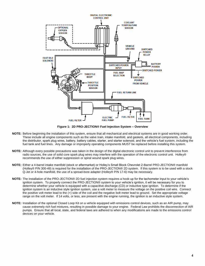
Figure 1: 2D PRO-JECTION® Fuel Injection System – Overview
NOTE: Before beginning the installation of this system, ensure that all mechanical and electrical systems are in good working order.
These include all engine components such as the valve train, intake manifold, and gaskets, all electrical components, including the distributor, spark plug wires, battery, battery cables, starter, and starter solenoid, and the vehicle’s fuel system, including the fuel tank and fuel lines. Any damage or improperly operating components MUST be replaced before installing this system.
NOTE: Although every possible precautions was taken in the design of the digital electronic control unit to prevent interference from
radio sources, the use of solid core spark plug wires may interfere with the operation of the electronic control unit. Holley® recommends the use of either suppression or spiral wound spark plug wires.
NOTE: Either a 4-barrel intake manifold (stock or aftermarket) or Holley’s Small Block Chevrolet 2-Barrel PRO-JECTION® manifold
(Holley® P/N 300-49) is required for the installation of the PRO-JECTION® 2D system. If this system is to be used with a stock Q-Jet or 4-hole manifold, the use of a spread-bore adapter (Holley® P/N 17-6) may be necessary.
NOTE: The installation of the PRO-JECTION® 2D fuel injection system requires a hook-up for the tachometer input to your vehicle’s
ignition system. To properly connect the PRO-JECTION® system to your vehicle’s ignition, it will be necessary for you to determine whether your vehicle is equipped with a capacitive discharge (CD) or inductive type ignition. To determine if the ignition system is an inductive style ignition system, use a volt meter to measure the voltage on the positive coil wire. Connect the positive volt meter lead to the (+) side of the coil and the negative bolt meter lead to ground. Set the appropriate voltage range on the volt meter. If 14 volts, or less, are present with the engine running, the ignition is an inductive style system.
NOTE: Installation of the optional Closed Loop Kit on a vehicle equipped with emissions control devices, such as an AIR pump, may
cause extremely rich fuel mixtures, resulting in possible damage to your engine. Federal Law prohibits the disconnection of AIR pumps. Ensure that all local, state, and federal laws are adhered to when any modifications are made to the emissions control devices on your vehicle.
5
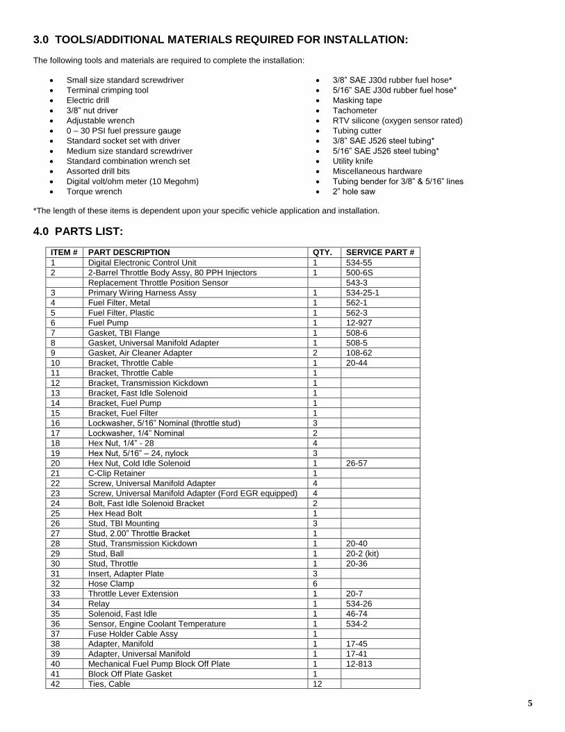
3.0 TOOLS/ADDITIONAL MATERIALS REQUIRED FOR INSTALLATION: The following tools and materials are required to complete the installation:
Small size standard screwdriver
Terminal crimping tool
Electric drill
3/8” nut driver
Adjustable wrench
0 – 30 PSI fuel pressure gauge
3/8” SAE J30d rubber fuel hose*
5/16” SAE J30d rubber fuel hose*
Masking tape
Tachometer
RTV silicone (oxygen sensor rated)
Tubing cutter
Standard socket set with driver
Medium size standard screwdriver
Standard combination wrench set
Assorted drill bits
Digital volt/ohm meter (10 Megohm)
Torque wrench
3/8” SAE J526 steel tubing*
5/16” SAE J526 steel tubing*
Utility knife
Miscellaneous hardware
Tubing bender for 3/8” & 5/16” lines
2” hole saw *The length of these items is dependent upon your specific vehicle application and installation.
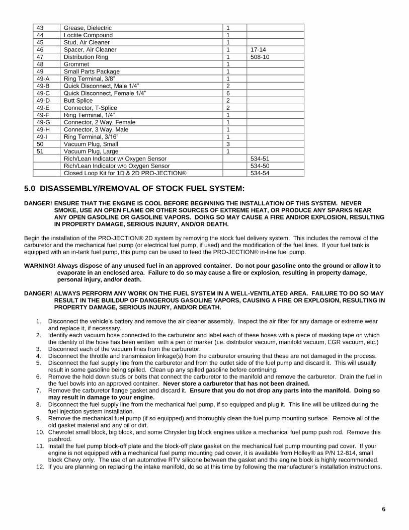
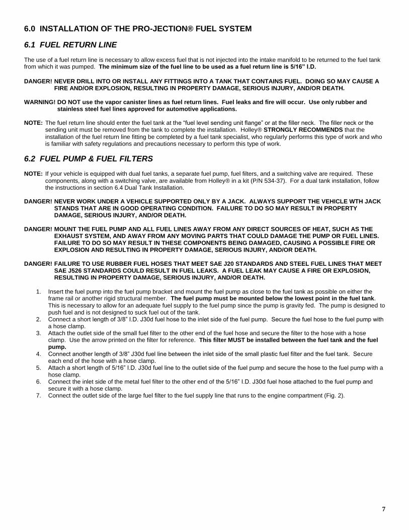
4.0 PARTS LIST:
ITEM # PART DESCRIPTION QTY. SERVICE PART #
1 Digital Electronic Control Unit 1 534-55
2 2-Barrel Throttle Body Assy, 80 PPH Injectors 1 500-6S
Replacement Throttle Position Sensor 543-3
3 Primary Wiring Harness Assy 1 534-25-1
4 Fuel Filter, Metal 1 562-1
5 Fuel Filter, Plastic 1 562-3
6 Fuel Pump 1 12-927
7 Gasket, TBI Flange 1 508-6
8 Gasket, Universal Manifold Adapter 1 508-5
9 Gasket, Air Cleaner Adapter 2 108-62
10 Bracket, Throttle Cable 1 20-44
11 Bracket, Throttle Cable 1
12 Bracket, Transmission Kickdown 1
13 Bracket, Fast Idle Solenoid 1
14 Bracket, Fuel Pump 1
15 Bracket, Fuel Filter 1
16 Lockwasher, 5/16” Nominal (throttle stud) 3
17 Lockwasher, 1/4” Nominal 2
18 Hex Nut, 1/4” - 28 4
19 Hex Nut, 5/16” – 24, nylock 3
20 Hex Nut, Cold Idle Solenoid 1 26-57
21 C-Clip Retainer 1
22 Screw, Universal Manifold Adapter 4
23 Screw, Universal Manifold Adapter (Ford EGR equipped) 4
24 Bolt, Fast Idle Solenoid Bracket 2
25 Hex Head Bolt 1
26 Stud, TBI Mounting 3
27 Stud, 2.00” Throttle Bracket 1
28 Stud, Transmission Kickdown 1 20-40
29 Stud, Ball 1 20-2 (kit)
30 Stud, Throttle 1 20-36
31 Insert, Adapter Plate 3
32 Hose Clamp 6
33 Throttle Lever Extension 1 20-7
34 Relay 1 534-26
35 Solenoid, Fast Idle 1 46-74
36 Sensor, Engine Coolant Temperature 1 534-2
37 Fuse Holder Cable Assy 1
38 Adapter, Manifold 1 17-45
39 Adapter, Universal Manifold 1 17-41
40 Mechanical Fuel Pump Block Off Plate 1 12-813
41 Block Off Plate Gasket 1
42 Ties, Cable 12
6
43 Grease, Dielectric 1
44 Loctite Compound 1
45 Stud, Air Cleaner 1
46 Spacer, Air Cleaner 1 17-14
47 Distribution Ring 1 508-10
48 Grommet 1
49 Small Parts Package 1
49-A Ring Terminal, 3/8” 1
49-B Quick Disconnect, Male 1/4” 2
49-C Quick Disconnect, Female 1/4” 6
49-D Butt Splice 2
49-E Connector, T-Splice 2
49-F Ring Terminal, 1/4” 1
49-G Connector, 2 Way, Female 1
49-H Connector, 3 Way, Male 1
49-I Ring Terminal, 3/16” 1
50 Vacuum Plug, Small 3
51 Vacuum Plug, Large 1
Rich/Lean Indicator w/ Oxygen Sensor 534-51
Rich/Lean Indicator w/o Oxygen Sensor 534-50
Closed Loop Kit for 1D & 2D PRO-JECTION® 534-54
5.0 DISASSEMBLY/REMOVAL OF STOCK FUEL SYSTEM: DANGER! ENSURE THAT THE ENGINE IS COOL BEFORE BEGINNING THE INSTALLATION OF THIS SYSTEM. NEVER
SMOKE, USE AN OPEN FLAME OR OTHER SOURCES OF EXTREME HEAT, OR PRODUCE ANY SPARKS NEAR ANY OPEN GASOLINE OR GASOLINE VAPORS. DOING SO MAY CAUSE A FIRE AND/OR EXPLOSION, RESULTING IN PROPERTY DAMAGE, SERIOUS INJURY, AND/OR DEATH.
Begin the installation of the PRO-JECTION® 2D system by removing the stock fuel delivery system. This includes the removal of the carburetor and the mechanical fuel pump (or electrical fuel pump, if used) and the modification of the fuel lines. If your fuel tank is equipped with an in-tank fuel pump, this pump can be used to feed the PRO-JECTION® in-line fuel pump. WARNING! Always dispose of any unused fuel in an approved container. Do not pour gasoline onto the ground or allow it to
evaporate in an enclosed area. Failure to do so may cause a fire or explosion, resulting in property damage, personal injury, and/or death.
DANGER! ALWAYS PERFORM ANY WORK ON THE FUEL SYSTEM IN A WELL-VENTILATED AREA. FAILURE TO DO SO MAY
RESULT IN THE BUILDUP OF DANGEROUS GASOLINE VAPORS, CAUSING A FIRE OR EXPLOSION, RESULTING IN PROPERTY DAMAGE, SERIOUS INJURY, AND/OR DEATH.
1. Disconnect the vehicle’s battery and remove the air cleaner assembly. Inspect the air filter for any damage or extreme wear
and replace it, if necessary. 2. Identify each vacuum hose connected to the carburetor and label each of these hoses with a piece of masking tape on which
the identity of the hose has been written with a pen or marker (i.e. distributor vacuum, manifold vacuum, EGR vacuum, etc.) 3. Disconnect each of the vacuum lines from the carburetor. 4. Disconnect the throttle and transmission linkage(s) from the carburetor ensuring that these are not damaged in the process. 5. Disconnect the fuel supply line from the carburetor and from the outlet side of the fuel pump and discard it. This will usually
result in some gasoline being spilled. Clean up any spilled gasoline before continuing. 6. Remove the hold down studs or bolts that connect the carburetor to the manifold and remove the carburetor. Drain the fuel in
the fuel bowls into an approved container. Never store a carburetor that has not been drained. 7. Remove the carburetor flange gasket and discard it. Ensure that you do not drop any parts into the manifold. Doing so
may result in damage to your engine.
8. Disconnect the fuel supply line from the mechanical fuel pump, if so equipped and plug it. This line will be utilized during the fuel injection system installation.
9. Remove the mechanical fuel pump (if so equipped) and thoroughly clean the fuel pump mounting surface. Remove all of the old gasket material and any oil or dirt.
10. Chevrolet small block, big block, and some Chrysler big block engines utilize a mechanical fuel pump push rod. Remove this pushrod.
11. Install the fuel pump block-off plate and the block-off plate gasket on the mechanical fuel pump mounting pad cover. If your engine is not equipped with a mechanical fuel pump mounting pad cover, it is available from Holley® as P/N 12-814, small block Chevy only. The use of an automotive RTV silicone between the gasket and the engine block is highly recommended.
12. If you are planning on replacing the intake manifold, do so at this time by following the manufacturer’s installation instructions.
7
6.0 INSTALLATION OF THE PRO-JECTION® FUEL SYSTEM
6.1 FUEL RETURN LINE The use of a fuel return line is necessary to allow excess fuel that is not injected into the intake manifold to be returned to the fuel tank from which it was pumped. The minimum size of the fuel line to be used as a fuel return line is 5/16” I.D.
DANGER! NEVER DRILL INTO OR INSTALL ANY FITTINGS INTO A TANK THAT CONTAINS FUEL. DOING SO MAY CAUSE A
FIRE AND/OR EXPLOSION, RESULTING IN PROPERTY DAMAGE, SERIOUS INJURY, AND/OR DEATH.
WARNING! DO NOT use the vapor canister lines as fuel return lines. Fuel leaks and fire will occur. Use only rubber and
stainless steel fuel lines approved for automotive applications.
NOTE: The fuel return line should enter the fuel tank at the “fuel level sending unit flange” or at the filler neck. The filler neck or the
sending unit must be removed from the tank to complete the installation. Holley® STRONGLY RECOMMENDS that the
installation of the fuel return line fitting be completed by a fuel tank specialist, who regularly performs this type of work and who is familiar with safety regulations and precautions necessary to perform this type of work.
6.2 FUEL PUMP & FUEL FILTERS NOTE: If your vehicle is equipped with dual fuel tanks, a separate fuel pump, fuel filters, and a switching valve are required. These
components, along with a switching valve, are available from Holley® in a kit (P/N 534-37). For a dual tank installation, follow the instructions in section 6.4 Dual Tank Installation.
DANGER! NEVER WORK UNDER A VEHICLE SUPPORTED ONLY BY A JACK. ALWAYS SUPPORT THE VEHICLE WTH JACK
STANDS THAT ARE IN GOOD OPERATING CONDITION. FAILURE TO DO SO MAY RESULT IN PROPERTY DAMAGE, SERIOUS INJURY, AND/OR DEATH.
DANGER! MOUNT THE FUEL PUMP AND ALL FUEL LINES AWAY FROM ANY DIRECT SOURCES OF HEAT, SUCH AS THE
EXHAUST SYSTEM, AND AWAY FROM ANY MOVING PARTS THAT COULD DAMAGE THE PUMP OR FUEL LINES. FAILURE TO DO SO MAY RESULT IN THESE COMPONENTS BEING DAMAGED, CAUSING A POSSIBLE FIRE OR EXPLOSION AND RESULTING IN PROPERTY DAMAGE, SERIOUS INJURY, AND/OR DEATH.
DANGER! FAILURE TO USE RUBBER FUEL HOSES THAT MEET SAE J20 STANDARDS AND STEEL FUEL LINES THAT MEET
SAE J526 STANDARDS COULD RESULT IN FUEL LEAKS. A FUEL LEAK MAY CAUSE A FIRE OR EXPLOSION, RESULTING IN PROPERTY DAMAGE, SERIOUS INJURY, AND/OR DEATH.
1. Insert the fuel pump into the fuel pump bracket and mount the fuel pump as close to the fuel tank as possible on either the frame rail or another rigid structural member. The fuel pump must be mounted below the lowest point in the fuel tank.
This is necessary to allow for an adequate fuel supply to the fuel pump since the pump is gravity fed. The pump is designed to push fuel and is not designed to suck fuel out of the tank.
2. Connect a short length of 3/8” I.D. J30d fuel hose to the inlet side of the fuel pump. Secure the fuel hose to the fuel pump with a hose clamp.
3. Attach the outlet side of the small fuel filter to the other end of the fuel hose and secure the filter to the hose with a hose clamp. Use the arrow printed on the filter for reference. This filter MUST be installed between the fuel tank and the fuel pump.
4. Connect another length of 3/8” J30d fuel line between the inlet side of the small plastic fuel filter and the fuel tank. Secure each end of the hose with a hose clamp.
5. Attach a short length of 5/16” I.D. J30d fuel line to the outlet side of the fuel pump and secure the hose to the fuel pump with a hose clamp.
6. Connect the inlet side of the metal fuel filter to the other end of the 5/16” I.D. J30d fuel hose attached to the fuel pump and secure it with a hose clamp.
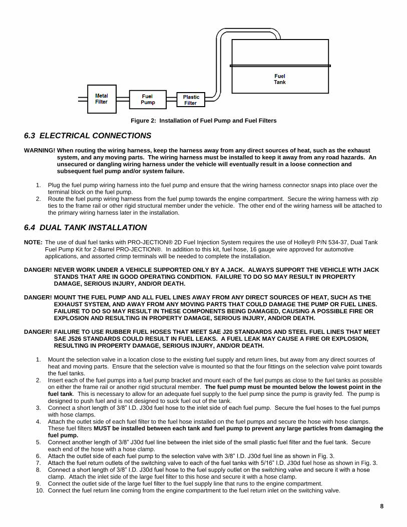
7. Connect the outlet side of the large fuel filter to the fuel supply line that runs to the engine compartment (Fig. 2).
8
Figure 2: Installation of Fuel Pump and Fuel Filters
6.3 ELECTRICAL CONNECTIONS WARNING! When routing the wiring harness, keep the harness away from any direct sources of heat, such as the exhaust
system, and any moving parts. The wiring harness must be installed to keep it away from any road hazards. An unsecured or dangling wiring harness under the vehicle will eventually result in a loose connection and subsequent fuel pump and/or system failure.
1. Plug the fuel pump wiring harness into the fuel pump and ensure that the wiring harness connector snaps into place over the terminal block on the fuel pump.
2. Route the fuel pump wiring harness from the fuel pump towards the engine compartment. Secure the wiring harness with zip ties to the frame rail or other rigid structural member under the vehicle. The other end of the wiring harness will be attached to the primary wiring harness later in the installation.
6.4 DUAL TANK INSTALLATION NOTE: The use of dual fuel tanks with PRO-JECTION® 2D Fuel Injection System requires the use of Holley® P/N 534-37, Dual Tank
Fuel Pump Kit for 2-Barrel PRO-JECTION®. In addition to this kit, fuel hose, 16 gauge wire approved for automotive applications, and assorted crimp terminals will be needed to complete the installation.
DANGER! NEVER WORK UNDER A VEHICLE SUPPORTED ONLY BY A JACK. ALWAYS SUPPORT THE VEHICLE WTH JACK
STANDS THAT ARE IN GOOD OPERATING CONDITION. FAILURE TO DO SO MAY RESULT IN PROPERTY DAMAGE, SERIOUS INJURY, AND/OR DEATH.
DANGER! MOUNT THE FUEL PUMP AND ALL FUEL LINES AWAY FROM ANY DIRECT SOURCES OF HEAT, SUCH AS THE
EXHAUST SYSTEM, AND AWAY FROM ANY MOVING PARTS THAT COULD DAMAGE THE PUMP OR FUEL LINES. FAILURE TO DO SO MAY RESULT IN THESE COMPONENTS BEING DAMAGED, CAUSING A POSSIBLE FIRE OR EXPLOSION AND RESULTING IN PROPERTY DAMAGE, SERIOUS INJURY, AND/OR DEATH.
DANGER! FAILURE TO USE RUBBER FUEL HOSES THAT MEET SAE J20 STANDARDS AND STEEL FUEL LINES THAT MEET
SAE J526 STANDARDS COULD RESULT IN FUEL LEAKS. A FUEL LEAK MAY CAUSE A FIRE OR EXPLOSION, RESULTING IN PROPERTY DAMAGE, SERIOUS INJURY, AND/OR DEATH.
1. Mount the selection valve in a location close to the existing fuel supply and return lines, but away from any direct sources of
heat and moving parts. Ensure that the selection valve is mounted so that the four fittings on the selection valve point towards the fuel tanks.
2. Insert each of the fuel pumps into a fuel pump bracket and mount each of the fuel pumps as close to the fuel tanks as possible on either the frame rail or another rigid structural member. The fuel pump must be mounted below the lowest point in the fuel tank. This is necessary to allow for an adequate fuel supply to the fuel pump since the pump is gravity fed. The pump is
designed to push fuel and is not designed to suck fuel out of the tank. 3. Connect a short length of 3/8” I.D. J30d fuel hose to the inlet side of each fuel pump. Secure the fuel hoses to the fuel pumps
with hose clamps. 4. Attach the outlet side of each fuel filter to the fuel hose installed on the fuel pumps and secure the hose with hose clamps.
These fuel filters MUST be installed between each tank and fuel pump to prevent any large particles from damaging the fuel pump.
5. Connect another length of 3/8” J30d fuel line between the inlet side of the small plastic fuel filter and the fuel tank. Secure each end of the hose with a hose clamp.
6. Attach the outlet side of each fuel pump to the selection valve with 3/8” I.D. J30d fuel line as shown in Fig. 3. 7. Attach the fuel return outlets of the switching valve to each of the fuel tanks with 5/16” I.D. J30d fuel hose as shown in Fig. 3. 8. Connect a short length of 3/8” I.D. J30d fuel hose to the fuel supply outlet on the switching valve and secure it with a hose
clamp. Attach the inlet side of the large fuel filter to this hose and secure it with a hose clamp. 9. Connect the outlet side of the large fuel filter to the fuel supply line that runs to the engine compartment. 10. Connect the fuel return line coming from the engine compartment to the fuel return inlet on the switching valve.
9
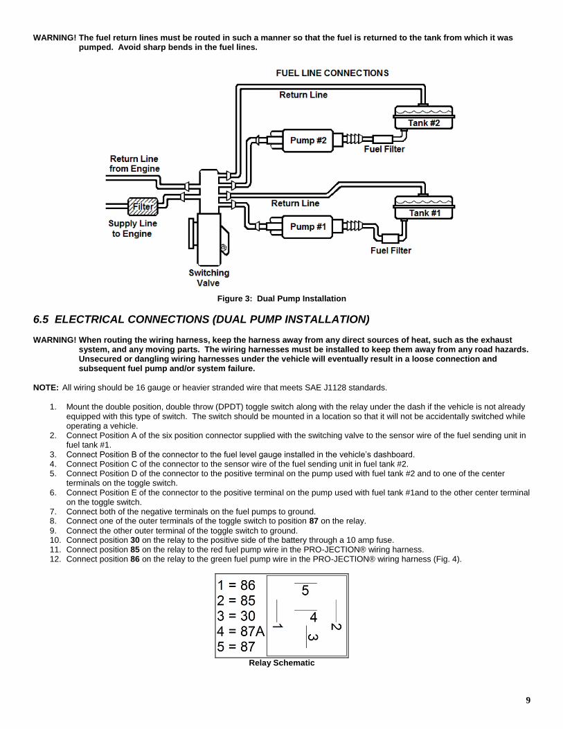
WARNING! The fuel return lines must be routed in such a manner so that the fuel is returned to the tank from which it was pumped. Avoid sharp bends in the fuel lines.
Figure 3: Dual Pump Installation
6.5 ELECTRICAL CONNECTIONS (DUAL PUMP INSTALLATION) WARNING! When routing the wiring harness, keep the harness away from any direct sources of heat, such as the exhaust
system, and any moving parts. The wiring harnesses must be installed to keep them away from any road hazards. Unsecured or dangling wiring harnesses under the vehicle will eventually result in a loose connection and subsequent fuel pump and/or system failure.
NOTE: All wiring should be 16 gauge or heavier stranded wire that meets SAE J1128 standards.
1. Mount the double position, double throw (DPDT) toggle switch along with the relay under the dash if the vehicle is not already
equipped with this type of switch. The switch should be mounted in a location so that it will not be accidentally switched while operating a vehicle.
2. Connect Position A of the six position connector supplied with the switching valve to the sensor wire of the fuel sending unit in fuel tank #1.
3. Connect Position B of the connector to the fuel level gauge installed in the vehicle’s dashboard. 4. Connect Position C of the connector to the sensor wire of the fuel sending unit in fuel tank #2. 5. Connect Position D of the connector to the positive terminal on the pump used with fuel tank #2 and to one of the center
terminals on the toggle switch. 6. Connect Position E of the connector to the positive terminal on the pump used with fuel tank #1and to the other center terminal
on the toggle switch. 7. Connect both of the negative terminals on the fuel pumps to ground. 8. Connect one of the outer terminals of the toggle switch to position 87 on the relay.
9. Connect the other outer terminal of the toggle switch to ground. 10. Connect position 30 on the relay to the positive side of the battery through a 10 amp fuse. 11. Connect position 85 on the relay to the red fuel pump wire in the PRO-JECTION® wiring harness. 12. Connect position 86 on the relay to the green fuel pump wire in the PRO-JECTION® wiring harness (Fig. 4).
Relay Schematic
10
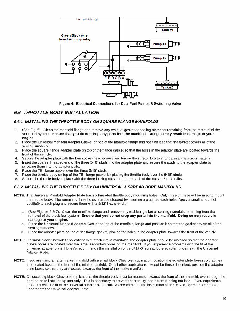
Figure 4: Electrical Connections for Dual Fuel Pumps & Switching Valve
6.6 THROTTLE BODY INSTALLATION
6.6.1 INSTALLING THE THROTTLE BODY ON SQUARE FLANGE MANIFOLDS 1. (See Fig. 5). Clean the manifold flange and remove any residual gasket or sealing materials remaining from the removal of the
stock fuel system. Ensure that you do not drop any parts into the manifold. Doing so may result in damage to your engine.
2. Place the Universal Manifold Adapter Gasket on top of the manifold flange and position it so that the gasket covers all of the sealing surfaces
3. Place the square flange adapter plate on top of the flange gasket so that the holes in the adapter plate are located towards the front of the vehicle.
4. Secure the adapter plate with the four socket-head screws and torque the screws to 5 to 7 ft./lbs. in a criss-cross pattern. 5. Insert the coarse threaded end of the three 5/16” studs into the adapter plate and secure the studs to the adapter plate by
screwing them into the adapter plate. 6. Place the TBI flange gasket over the three 5/16” studs. 7. Place the throttle body on top of the TBI flange gasket by placing the throttle body over the 5/16” studs. 8. Secure the throttle body in place with the three locking nuts and torque each of the nuts to 5 to 7 ft./lbs.
6.6.2 INSTALLING THE THROTTLE BODY ON UNIVERSAL & SPREAD BORE MANIFOLDS NOTE: The Universal Manifold Adapter Plate has six threaded throttle body mounting holes. Only three of these will be used to mount
the throttle body. The remaining three holes must be plugged by inserting a plug into each hole. Apply a small amount of Loctite® to each plug and secure them with a 5/32” hex wrench.
1. (See Figures 6 & 7). Clean the manifold flange and remove any residual gasket or sealing materials remaining from the
removal of the stock fuel system. Ensure that you do not drop any parts into the manifold. Doing so may result in damage to your engine.
2. Place the Universal Manifold Adapter Gasket on top of the manifold flange and position it so that the gasket covers all of the sealing surfaces.
3. Place the adapter plate on top of the flange gasket, placing the holes in the adapter plate towards the front of the vehicle.
NOTE: On small block Chevrolet applications with stock intake manifolds, the adapter plate should be installed so that the adapter
plate’s bores are located over the large, secondary bores on the manifold. If you experience problems with the fit of the universal adapter plate, Holley® recommends the installation of part #17-6, spread bore adapter, underneath the Universal Adapter Plate.
NOTE: If you are using an aftermarket manifold with a small block Chevrolet application, position the adapter plate bores so that they
are located towards the front of the intake manifold. On all other applications, except for those described, position the adapter plate bores so that they are located towards the front of the intake manifold.
NOTE: On stock big block Chevrolet applications, the throttle body must be mounted towards the front of the manifold, even though the
bore holes will not line up correctly. This is necessary to prevent the front cylinders from running too lean. If you experience problems with the fit of the universal adapter plate, Holley® recommends the installation of part #17-6, spread bore adapter, underneath the Universal Adapter Plate.
11
4. Secure the adapter plate to the manifold with the four socket-head screws and torque them to 5 to 7 lb./ft. in a criss-cross pattern.
5. Insert the coarse threaded end of the three 5/16” studs into the adapter plate and secure the studs to the adapter plate by screwing the studs into the adapter plate.
6. Place the TBI flange gasket over the three 5/16” studs. 7. Place the throttle body on top of the TBI flange gasket by placing the throttle body over the 5/16” studs. 8. Secure the throttle body in place with the three locking nuts and torque each of the nuts to 5 to 7 lb./ft.
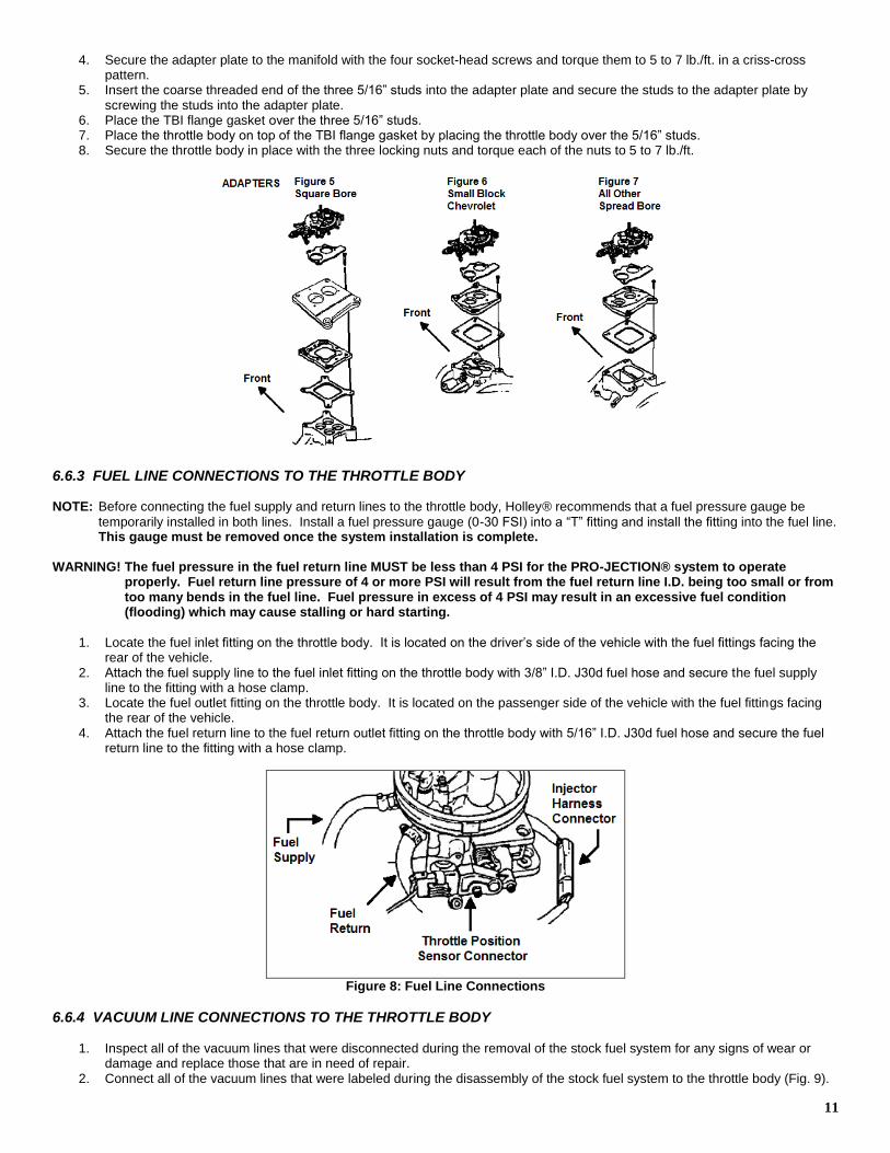
6.6.3 FUEL LINE CONNECTIONS TO THE THROTTLE BODY NOTE: Before connecting the fuel supply and return lines to the throttle body, Holley® recommends that a fuel pressure gauge be
temporarily installed in both lines. Install a fuel pressure gauge (0-30 FSI) into a “T” fitting and install the fitting into the fuel line. This gauge must be removed once the system installation is complete.
WARNING! The fuel pressure in the fuel return line MUST be less than 4 PSI for the PRO-JECTION® system to operate
properly. Fuel return line pressure of 4 or more PSI will result from the fuel return line I.D. being too small or from too many bends in the fuel line. Fuel pressure in excess of 4 PSI may result in an excessive fuel condition (flooding) which may cause stalling or hard starting.
1. Locate the fuel inlet fitting on the throttle body. It is located on the driver’s side of the vehicle with the fuel fittings facing the rear of the vehicle.
2. Attach the fuel supply line to the fuel inlet fitting on the throttle body with 3/8” I.D. J30d fuel hose and secure the fuel supply line to the fitting with a hose clamp.
3. Locate the fuel outlet fitting on the throttle body. It is located on the passenger side of the vehicle with the fuel fittings facing the rear of the vehicle.
4. Attach the fuel return line to the fuel return outlet fitting on the throttle body with 5/16” I.D. J30d fuel hose and secure the fuel return line to the fitting with a hose clamp.
Figure 8: Fuel Line Connections
6.6.4 VACUUM LINE CONNECTIONS TO THE THROTTLE BODY
1. Inspect all of the vacuum lines that were disconnected during the removal of the stock fuel system for any signs of wear or damage and replace those that are in need of repair.
2. Connect all of the vacuum lines that were labeled during the disassembly of the stock fuel system to the throttle body (Fig. 9).
12
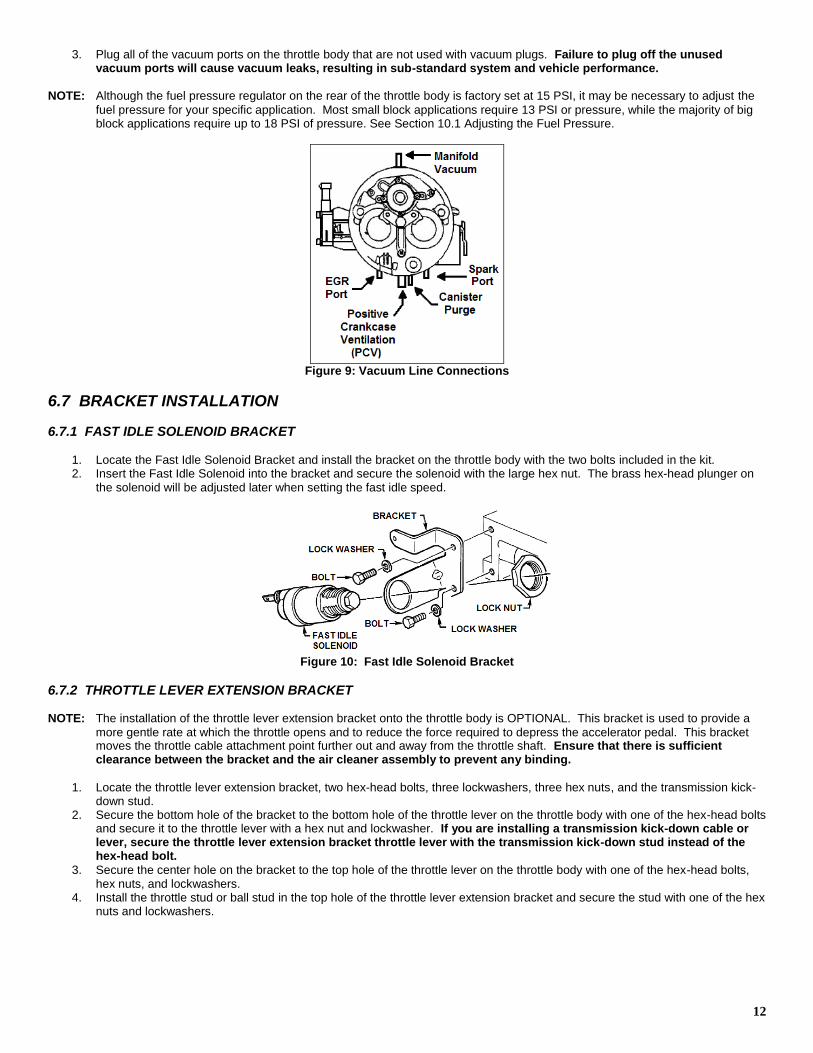
3. Plug all of the vacuum ports on the throttle body that are not used with vacuum plugs. Failure to plug off the unused vacuum ports will cause vacuum leaks, resulting in sub-standard system and vehicle performance.
NOTE: Although the fuel pressure regulator on the rear of the throttle body is factory set at 15 PSI, it may be necessary to adjust the
fuel pressure for your specific application. Most small block applications require 13 PSI or pressure, while the majority of big block applications require up to 18 PSI of pressure. See Section 10.1 Adjusting the Fuel Pressure.
Figure 9: Vacuum Line Connections
6.7 BRACKET INSTALLATION
6.7.1 FAST IDLE SOLENOID BRACKET
1. Locate the Fast Idle Solenoid Bracket and install the bracket on the throttle body with the two bolts included in the kit. 2. Insert the Fast Idle Solenoid into the bracket and secure the solenoid with the large hex nut. The brass hex-head plunger on
the solenoid will be adjusted later when setting the fast idle speed.
Figure 10: Fast Idle Solenoid Bracket
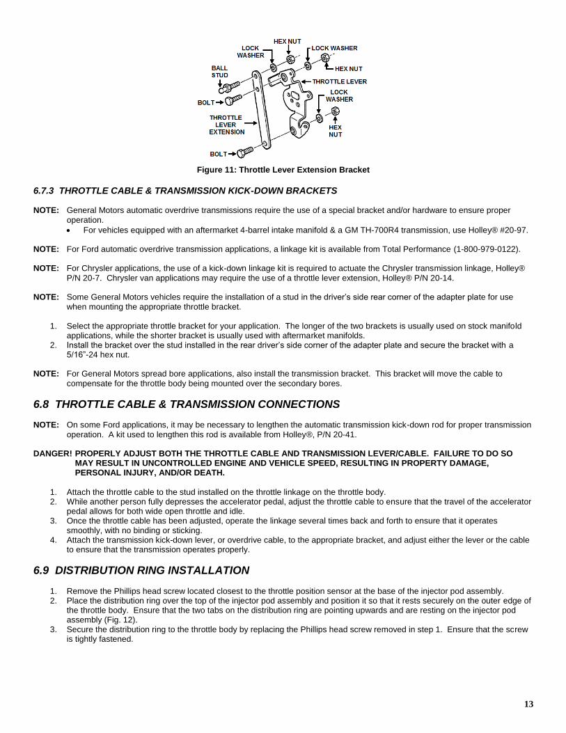
6.7.2 THROTTLE LEVER EXTENSION BRACKET NOTE: The installation of the throttle lever extension bracket onto the throttle body is OPTIONAL. This bracket is used to provide a
more gentle rate at which the throttle opens and to reduce the force required to depress the accelerator pedal. This bracket moves the throttle cable attachment point further out and away from the throttle shaft. Ensure that there is sufficient clearance between the bracket and the air cleaner assembly to prevent any binding.
1. Locate the throttle lever extension bracket, two hex-head bolts, three lockwashers, three hex nuts, and the transmission kick-
down stud. 2. Secure the bottom hole of the bracket to the bottom hole of the throttle lever on the throttle body with one of the hex-head bolts
and secure it to the throttle lever with a hex nut and lockwasher. If you are installing a transmission kick-down cable or lever, secure the throttle lever extension bracket throttle lever with the transmission kick-down stud instead of the hex-head bolt.
3. Secure the center hole on the bracket to the top hole of the throttle lever on the throttle body with one of the hex-head bolts, hex nuts, and lockwashers.
4. Install the throttle stud or ball stud in the top hole of the throttle lever extension bracket and secure the stud with one of the hex nuts and lockwashers.
13
Figure 11: Throttle Lever Extension Bracket
6.7.3 THROTTLE CABLE & TRANSMISSION KICK-DOWN BRACKETS NOTE: General Motors automatic overdrive transmissions require the use of a special bracket and/or hardware to ensure proper
operation.
For vehicles equipped with an aftermarket 4-barrel intake manifold & a GM TH-700R4 transmission, use Holley® #20-97. NOTE: For Ford automatic overdrive transmission applications, a linkage kit is available from Total Performance (1-800-979-0122).
NOTE: For Chrysler applications, the use of a kick-down linkage kit is required to actuate the Chrysler transmission linkage, Holley®
P/N 20-7. Chrysler van applications may require the use of a throttle lever extension, Holley® P/N 20-14. NOTE: Some General Motors vehicles require the installation of a stud in the driver’s side rear corner of the adapter plate for use
when mounting the appropriate throttle bracket.
1. Select the appropriate throttle bracket for your application. The longer of the two brackets is usually used on stock manifold applications, while the shorter bracket is usually used with aftermarket manifolds.
2. Install the bracket over the stud installed in the rear driver’s side corner of the adapter plate and secure the bracket with a 5/16”-24 hex nut.
NOTE: For General Motors spread bore applications, also install the transmission bracket. This bracket will move the cable to
compensate for the throttle body being mounted over the secondary bores.
6.8 THROTTLE CABLE & TRANSMISSION CONNECTIONS NOTE: On some Ford applications, it may be necessary to lengthen the automatic transmission kick-down rod for proper transmission
operation. A kit used to lengthen this rod is available from Holley®, P/N 20-41. DANGER! PROPERLY ADJUST BOTH THE THROTTLE CABLE AND TRANSMISSION LEVER/CABLE. FAILURE TO DO SO
MAY RESULT IN UNCONTROLLED ENGINE AND VEHICLE SPEED, RESULTING IN PROPERTY DAMAGE, PERSONAL INJURY, AND/OR DEATH.
1. Attach the throttle cable to the stud installed on the throttle linkage on the throttle body. 2. While another person fully depresses the accelerator pedal, adjust the throttle cable to ensure that the travel of the accelerator
pedal allows for both wide open throttle and idle. 3. Once the throttle cable has been adjusted, operate the linkage several times back and forth to ensure that it operates
smoothly, with no binding or sticking. 4. Attach the transmission kick-down lever, or overdrive cable, to the appropriate bracket, and adjust either the lever or the cable
to ensure that the transmission operates properly.
6.9 DISTRIBUTION RING INSTALLATION
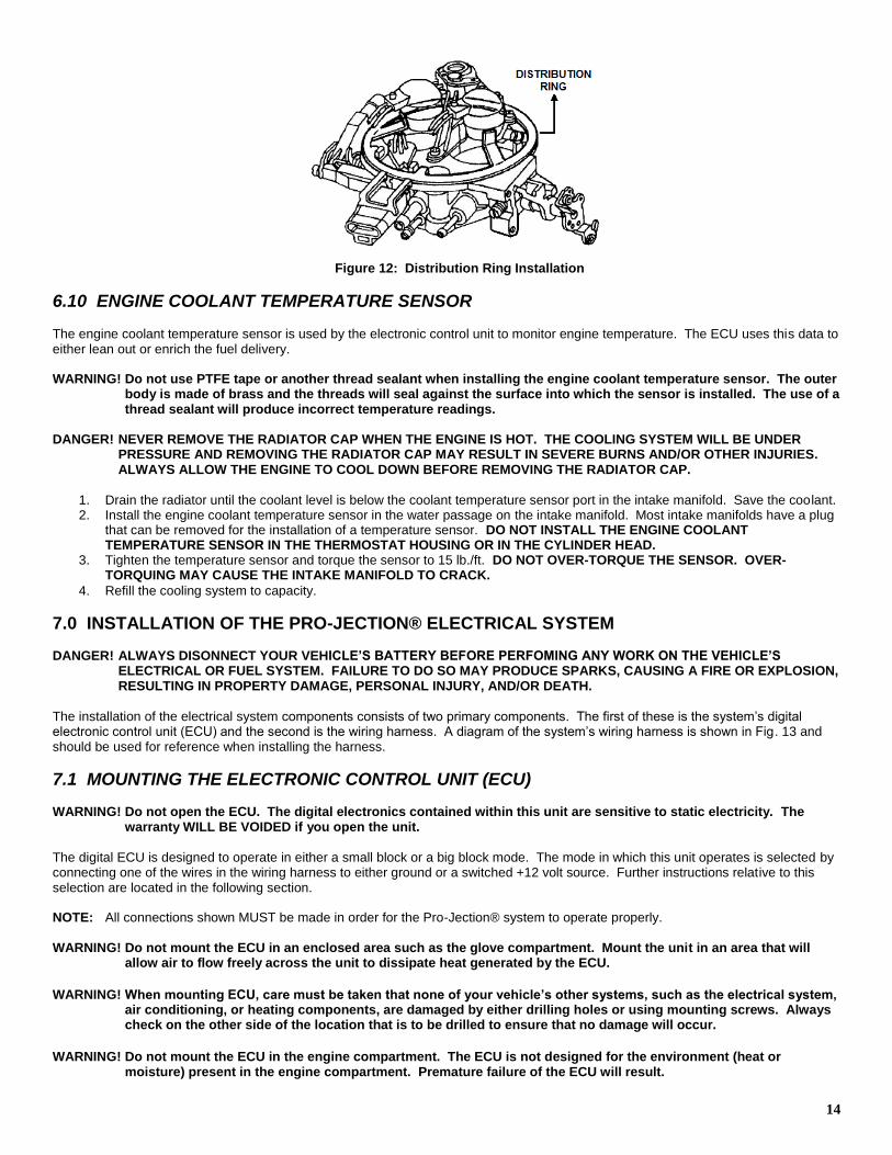
1. Remove the Phillips head screw located closest to the throttle position sensor at the base of the injector pod assembly. 2. Place the distribution ring over the top of the injector pod assembly and position it so that it rests securely on the outer edge of
the throttle body. Ensure that the two tabs on the distribution ring are pointing upwards and are resting on the injector pod assembly (Fig. 12).
3. Secure the distribution ring to the throttle body by replacing the Phillips head screw removed in step 1. Ensure that the screw is tightly fastened.
14
Figure 12: Distribution Ring Installation
6.10 ENGINE COOLANT TEMPERATURE SENSOR
The engine coolant temperature sensor is used by the electronic control unit to monitor engine temperature. The ECU uses this data to either lean out or enrich the fuel delivery. WARNING! Do not use PTFE tape or another thread sealant when installing the engine coolant temperature sensor. The outer
body is made of brass and the threads will seal against the surface into which the sensor is installed. The use of a thread sealant will produce incorrect temperature readings.
DANGER! NEVER REMOVE THE RADIATOR CAP WHEN THE ENGINE IS HOT. THE COOLING SYSTEM WILL BE UNDER
PRESSURE AND REMOVING THE RADIATOR CAP MAY RESULT IN SEVERE BURNS AND/OR OTHER INJURIES. ALWAYS ALLOW THE ENGINE TO COOL DOWN BEFORE REMOVING THE RADIATOR CAP.
1. Drain the radiator until the coolant level is below the coolant temperature sensor port in the intake manifold. Save the coolant. 2. Install the engine coolant temperature sensor in the water passage on the intake manifold. Most intake manifolds have a plug
that can be removed for the installation of a temperature sensor. DO NOT INSTALL THE ENGINE COOLANT TEMPERATURE SENSOR IN THE THERMOSTAT HOUSING OR IN THE CYLINDER HEAD.
3. Tighten the temperature sensor and torque the sensor to 15 lb./ft. DO NOT OVER-TORQUE THE SENSOR. OVER-TORQUING MAY CAUSE THE INTAKE MANIFOLD TO CRACK.
4. Refill the cooling system to capacity.
7.0 INSTALLATION OF THE PRO-JECTION® ELECTRICAL SYSTEM DANGER! ALWAYS DISONNECT YOUR VEHICLE’S BATTERY BEFORE PERFOMING ANY WORK ON THE VEHICLE’S
ELECTRICAL OR FUEL SYSTEM. FAILURE TO DO SO MAY PRODUCE SPARKS, CAUSING A FIRE OR EXPLOSION, RESULTING IN PROPERTY DAMAGE, PERSONAL INJURY, AND/OR DEATH.
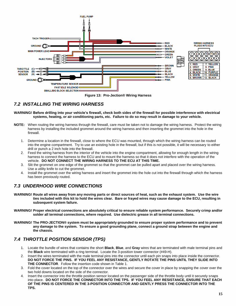
The installation of the electrical system components consists of two primary components. The first of these is the system’s digital electronic control unit (ECU) and the second is the wiring harness. A diagram of the system’s wiring harness is shown in Fig. 13 and should be used for reference when installing the harness.
7.1 MOUNTING THE ELECTRONIC CONTROL UNIT (ECU) WARNING! Do not open the ECU. The digital electronics contained within this unit are sensitive to static electricity. The
warranty WILL BE VOIDED if you open the unit.
The digital ECU is designed to operate in either a small block or a big block mode. The mode in which this unit operates is selected by connecting one of the wires in the wiring harness to either ground or a switched +12 volt source. Further instructions relative to this selection are located in the following section. NOTE: All connections shown MUST be made in order for the Pro-Jection® system to operate properly. WARNING! Do not mount the ECU in an enclosed area such as the glove compartment. Mount the unit in an area that will
allow air to flow freely across the unit to dissipate heat generated by the ECU.
WARNING! When mounting ECU, care must be taken that none of your vehicle’s other systems, such as the electrical system,
air conditioning, or heating components, are damaged by either drilling holes or using mounting screws. Always check on the other side of the location that is to be drilled to ensure that no damage will occur.
WARNING! Do not mount the ECU in the engine compartment. The ECU is not designed for the environment (heat or
moisture) present in the engine compartment. Premature failure of the ECU will result.
15
Figure 13: Pro-Jection® Wiring Harness
7.2 INSTALLING THE WIRING HARNESS WARNING! Before drilling into your vehicle’s firewall, check both sides of the firewall for possible interference with electrical
systems, heating, or air conditioning parts, etc. Failure to do so may result in damage to your vehicle. NOTE: When routing the wiring harness through the firewall, care must be taken not to damage the wiring harness. Protect the wiring
harness by installing the included grommet around the wiring harness and then inserting the grommet into the hole in the firewall.
1. Determine a location in the firewall, close to where the ECU was mounted, through which the wiring harness can be routed
into the engine compartment. Try to use an existing hole in the firewall, but if this is not possible, it will be necessary to either drill or punch a 2 inch hole into the firewall.
2. Feed the wiring harness from the interior of the vehicle into the engine compartment, allowing for enough length in the wiring harness to connect the harness to the ECU and to mount the harness so that it does not interfere with the operation of the vehicle. DO NOT CONNECT THE WIRING HARNESS TO THE ECU AT THIS TIME.
3. Slit the grommet on one edge of the grommet so that the grommet can be pulled apart and placed over the wiring harness. Use a utility knife to cut the grommet.
4. Install the grommet over the wiring harness and insert the grommet into the hole cut into the firewall through which the harness has been previously routed.
7.3 UNDERHOOD WIRE CONNECTIONS WARNING! Route all wires away from any moving parts or direct sources of heat, such as the exhaust system. Use the wire
ties included with this kit to hold the wires clear. Bare or frayed wires may cause damage to the ECU, resulting in subsequent system failure.
WARNING! Proper electrical connections are absolutely critical to ensure reliable system performance. Securely crimp and/or
solder all terminal connections, where required. Use dielectric grease in all terminal connections. WARNING! The PRO-JECTION® system must be appropriately grounded to ensure proper system performance and to prevent
any damage to the system. To ensure a good grounding plane, connect a ground strap between the engine and the chassis.
7.4 THROTTLE POSITION SENSOR (TPS)
1. Locate the bundle of wires that contains the short Black, Blue, and Gray wires that are terminated with male terminal pins and the Black wire terminated with a ring terminal. Locate the 3-position tower connector (#49-H).
2. Insert the wires terminated with the male terminal pins into the connector until each pin snaps into place inside the connector. DO NOT FORCE THE PINS. IF YOU FEEL ANY RESISTANCE, GENTLY ROTATE THE PINS UNTIL THEY SLIDE INTO THE CONNECTOR. Follow the insertion code shown in Table 1.
3. Fold the cover located on the top of the connector over the wires and secure the cover in place by snapping the cover over the two hold downs located on the side of the connector.
4. Insert the connector into the throttle position sensor located on the passenger side of the throttle body until it securely snaps into place. DO NOT FORCE THE CONNECTOR INTO THE TPS. IF YOU FEEL ANY RESISTANCE, ENSURE THAT EACH OF THE PINS IS CENTERED IN THE 3-POSITION CONNECTOR AND GENTLY PRESS THE CONNECTOR INTO THE TPS.
16
5. Connect the other black sire in this wire bundle that is terminated with a ring terminal to a good grounding location, such as the engine block or the intake manifold. Ensure that the surface to which the ring terminal will be connected is free of any dirt or oil. Improper grounding WILL result in substandard system performance. Holley® recommends connecting the ring
terminal to one of the intake manifold bolts and the use of a star washer (not included) to ensure that a good ground connection is maintained.
Connector Position
Wire Color
A Black
B Blue
C Gray Table 1: TPS Terminal Insertion
7.5 ENGINE COOLANT TEMPERAURE SENSOR
1. Locate the single brown wire in the wiring harness and one of the female quick-disconnect terminals (#49-C). 2. Route the brown wire away from any direct sources of heat towards the engine coolant temperature sensor and determine the
appropriate length of wire needed to connect the brown wire to the sensor. 3. Cut the brown wire to the appropriate length and strip 1/4” of the insulation off the wire. Twist the exposed wire strands and
insert the bare wire into the female quick-disconnect terminal. Securely crimp the female quick-disconnect terminal to the wire with a crimping tool. Test the crimp by pulling the wire and the crimp terminal.
4. Connect the brown wire to the engine coolant temperature sensor by inserting the tab located on the top of the coolant temperature sensor into the female quick-disconnect terminal.
7.6 FAST IDLE SOLENOID
1. Locate the yellow wire located in the harness and one of the female quick-disconnect terminals (#49-C). 2. Route the yellow wire away from any direct sources of heat towards the fast idle solenoid and determine the appropriate length
of wire needed to connect the yellow wire to the solenoid. 3. Cut the yellow wire to the appropriate length and strip 1/4” of the insulation off the wire. Twist the exposed wire strands and
insert the bare wire into the female quick-disconnect terminal. Securely crimp the female quick-disconnect terminal to the wire with a crimping tool. Test the crimp by pulling the wire and the crimp terminal.
4. Connect the yellow wire to the fast idle solenoid by inserting the tab located on the base of the fast idle solenoid sensor into the female quick-disconnect terminal.
7.7 FUEL INJECTORS
1. Locate the harness pigtail that contains the 4-position male connector to which one orange, one violet, and two red wires are attached.
2. Route this harness pigtail towards the front of the throttle body away from any direct sources of heat. 3. Plug the connector at the end of the pigtail into the oval connector at the front of the throttle body. Press the two connectors
together until the safety latch snaps into place.
7.8 FUEL PUMP
1. Locate the harness pigtail containing the red and green wires terminated with male terminal pins and the 2-position shroud connector (#49-G).
2. Cut off the two terminals and use the ring terminals supplied with the fuel pump. 3. The following is the correct wiring: Red Wire – positive (+) terminal on the fuel pump
Green Wire – negative (-) terminal on the fuel pump
7.9 PRIMARY POWER WARNING! Do not connect the primary power wire directly to the battery. Doing so will cause the PRO-JECTION® system to
be in continuous operation, causing possible damage to your vehicle’s battery and the PRO-JECTION® system. WARNING! Before drilling into your vehicle’s firewall, check both sides of the firewall for possible interference with electrical
systems, heating, or air conditioning parts, etc. Failure to do so may result in damage to your vehicle. WARNING! When connecting the system’s primary power, a relay must be used to prevent low voltage situations during the
system’s operation. DO NOT connect the primary power wire directly to a switched +12 volt source.
1. Locate the single red wire in the wiring harness, the power relay, the fuse holder cable assembly, and four (4) female quick-disconnect terminals (#49-C).
2. Mount the relay on the firewall with a self-tapping sheet metal screw (not included).
17
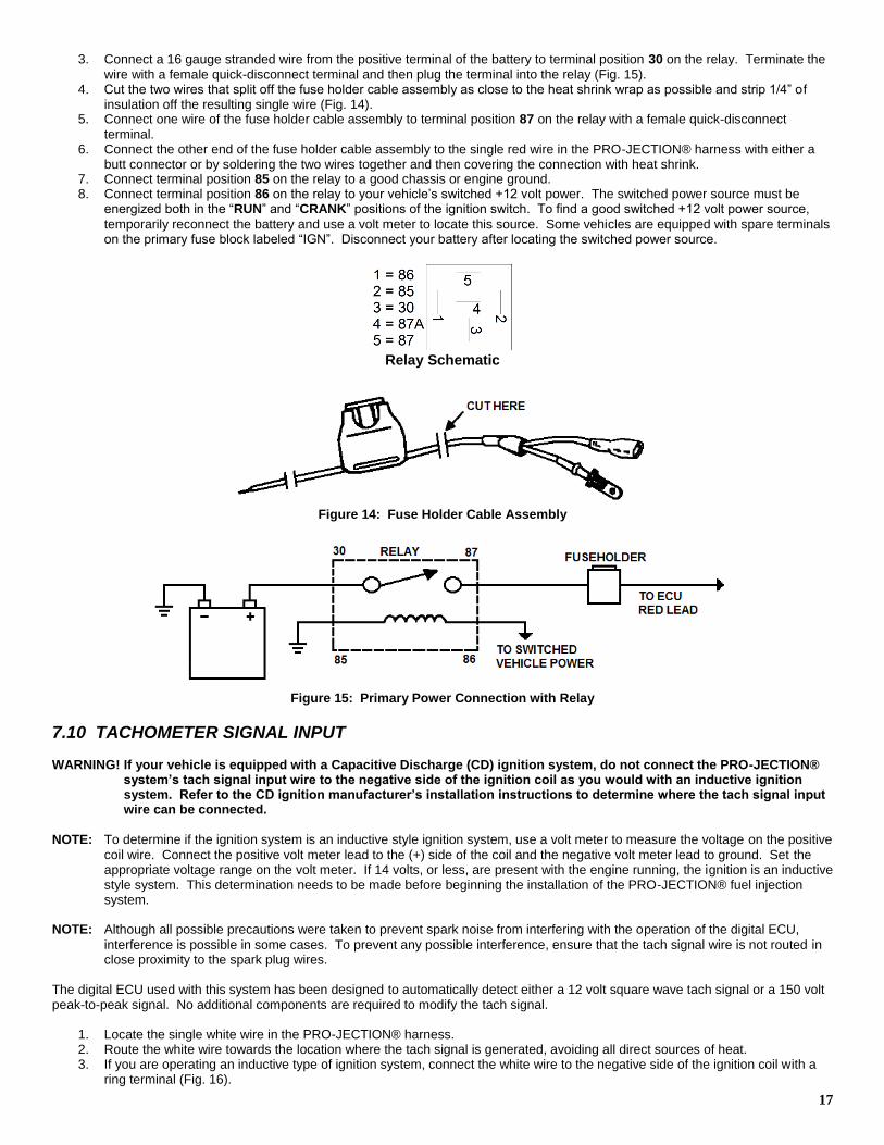
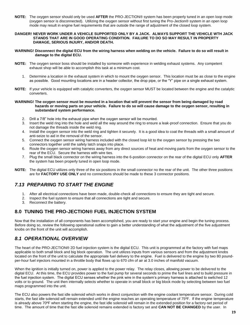
3. Connect a 16 gauge stranded wire from the positive terminal of the battery to terminal position 30 on the relay. Terminate the
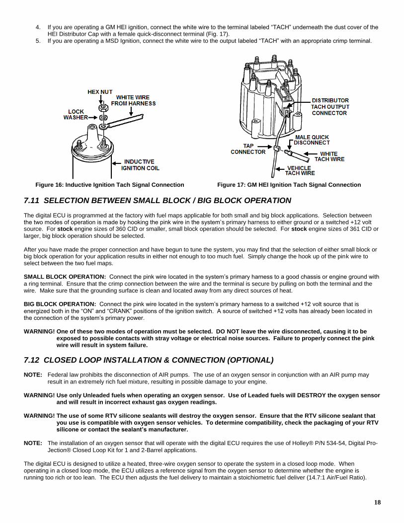
wire with a female quick-disconnect terminal and then plug the terminal into the relay (Fig. 15). 4. Cut the two wires that split off the fuse holder cable assembly as close to the heat shrink wrap as possible and strip 1/4” of
insulation off the resulting single wire (Fig. 14). 5. Connect one wire of the fuse holder cable assembly to terminal position 87 on the relay with a female quick-disconnect
terminal. 6. Connect the other end of the fuse holder cable assembly to the single red wire in the PRO-JECTION® harness with either a
butt connector or by soldering the two wires together and then covering the connection with heat shrink. 7. Connect terminal position 85 on the relay to a good chassis or engine ground. 8. Connect terminal position 86 on the relay to your vehicle’s switched +12 volt power. The switched power source must be
energized both in the “RUN” and “CRANK” positions of the ignition switch. To find a good switched +12 volt power source,
temporarily reconnect the battery and use a volt meter to locate this source. Some vehicles are equipped with spare terminals on the primary fuse block labeled “IGN”. Disconnect your battery after locating the switched power source.
Relay Schematic
Figure 14: Fuse Holder Cable Assembly
Figure 15: Primary Power Connection with Relay
7.10 TACHOMETER SIGNAL INPUT WARNING! If your vehicle is equipped with a Capacitive Discharge (CD) ignition system, do not connect the PRO-JECTION®
system’s tach signal input wire to the negative side of the ignition coil as you would with an inductive ignition system. Refer to the CD ignition manufacturer’s installation instructions to determine where the tach signal input wire can be connected.
NOTE: To determine if the ignition system is an inductive style ignition system, use a volt meter to measure the voltage on the positive
coil wire. Connect the positive volt meter lead to the (+) side of the coil and the negative volt meter lead to ground. Set the appropriate voltage range on the volt meter. If 14 volts, or less, are present with the engine running, the ignition is an inductive style system. This determination needs to be made before beginning the installation of the PRO-JECTION® fuel injection system.
NOTE: Although all possible precautions were taken to prevent spark noise from interfering with the operation of the digital ECU,
interference is possible in some cases. To prevent any possible interference, ensure that the tach signal wire is not routed in close proximity to the spark plug wires.
The digital ECU used with this system has been designed to automatically detect either a 12 volt square wave tach signal or a 150 volt peak-to-peak signal. No additional components are required to modify the tach signal.
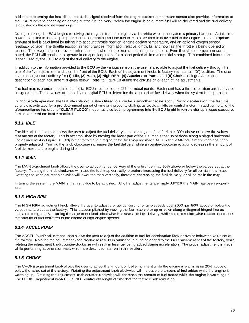
1. Locate the single white wire in the PRO-JECTION® harness. 2. Route the white wire towards the location where the tach signal is generated, avoiding all direct sources of heat. 3. If you are operating an inductive type of ignition system, connect the white wire to the negative side of the ignition coil with a
ring terminal (Fig. 16).
18
4. If you are operating a GM HEI ignition, connect the white wire to the terminal labeled “TACH” underneath the dust cover of the HEI Distributor Cap with a female quick-disconnect terminal (Fig. 17).
5. If you are operating a MSD Ignition, connect the white wire to the output labeled “TACH” with an appropriate crimp terminal.
Figure 16: Inductive Ignition Tach Signal Connection Figure 17: GM HEI Ignition Tach Signal Connection
7.11 SELECTION BETWEEN SMALL BLOCK / BIG BLOCK OPERATION The digital ECU is programmed at the factory with fuel maps applicable for both small and big block applications. Selection between the two modes of operation is made by hooking the pink wire in the system’s primary harness to either ground or a switched +12 volt source. For stock engine sizes of 360 CID or smaller, small block operation should be selected. For stock engine sizes of 361 CID or
larger, big block operation should be selected. After you have made the proper connection and have begun to tune the system, you may find that the selection of either small block or big block operation for your application results in either not enough to too much fuel. Simply change the hook up of the pink wire to select between the two fuel maps. SMALL BLOCK OPERATION: Connect the pink wire located in the system’s primary harness to a good chassis or engine ground with
a ring terminal. Ensure that the crimp connection between the wire and the terminal is secure by pulling on both the terminal and the wire. Make sure that the grounding surface is clean and located away from any direct sources of heat. BIG BLOCK OPERATION: Connect the pink wire located in the system’s primary harness to a switched +12 volt source that is
energized both in the “ON” and “CRANK” positions of the ignition switch. A source of switched +12 volts has already been located in the connection of the system’s primary power. WARNING! One of these two modes of operation must be selected. DO NOT leave the wire disconnected, causing it to be
exposed to possible contacts with stray voltage or electrical noise sources. Failure to properly connect the pink wire will result in system failure.
7.12 CLOSED LOOP INSTALLATION & CONNECTION (OPTIONAL) NOTE: Federal law prohibits the disconnection of AIR pumps. The use of an oxygen sensor in conjunction with an AIR pump may
result in an extremely rich fuel mixture, resulting in possible damage to your engine. WARNING! Use only Unleaded fuels when operating an oxygen sensor. Use of Leaded fuels will DESTROY the oxygen sensor
and will result in incorrect exhaust gas oxygen readings. WARNING! The use of some RTV silicone sealants will destroy the oxygen sensor. Ensure that the RTV silicone sealant that
you use is compatible with oxygen sensor vehicles. To determine compatibility, check the packaging of your RTV silicone or contact the sealant’s manufacturer.
NOTE: The installation of an oxygen sensor that will operate with the digital ECU requires the use of Holley® P/N 534-54, Digital Pro-
Jection® Closed Loop Kit for 1 and 2-Barrel applications. The digital ECU is designed to utilize a heated, three-wire oxygen sensor to operate the system in a closed loop mode. When operating in a closed loop mode, the ECU utilizes a reference signal from the oxygen sensor to determine whether the engine is running too rich or too lean. The ECU then adjusts the fuel delivery to maintain a stoichiometric fuel deliver (14.7:1 Air/Fuel Ratio).
19
NOTE: The oxygen sensor should only be used AFTER the PRO-JECTION® system has been properly tuned in an open loop mode
(oxygen sensor is disconnected). Utilizing the oxygen sensor without first tuning the Pro-Jection® system in an open loop mode may result in engine fuel requirements that are outside the range of adjustment of the closed loop system.
DANGER! NEVER WORK UNDER A VEHICLE SUPPORTED ONLY BY A JACK. ALWAYS SUPPORT THE VEHICLE WTH JACK
STANDS THAT ARE IN GOOD OPERATING CONDITION. FAILURE TO DO SO MAY RESULT IN PROPERTY DAMAGE, SERIOUS INJURY, AND/OR DEATH.
WARNING! Disconnect the digital ECU from the wiring harness when welding on the vehicle. Failure to do so will result in
damage to the digital ECU. NOTE: The oxygen sensor boss should be installed by someone with experience in welding exhaust systems. Any competent
exhaust shop will be able to accomplish this task at a minimum cost.
1. Determine a location in the exhaust system in which to mount the oxygen sensor. This location must be as close to the engine as possible. Good mounting locations are in a header collector, the drop pipe, or the “Y” pipe on a single exhaust system.
NOTE: If your vehicle is equipped with catalytic converters, the oxygen sensor MUST be located between the engine and the catalytic
converters. WARNING! The oxygen sensor must be mounted in a location that will prevent the sensor from being damaged by road
hazards or moving parts on your vehicle. Failure to do so will cause damage to the oxygen sensor, resulting in substandard system performance.
2. Drill a 7/8” hole into the exhaust pipe when the oxygen sensor will be mounted. 3. Insert the weld ring into the hole and weld all the way around the ring to ensure a leak-proof connection. Ensure that you do
not damage the threads inside the weld ring. 4. Install the oxygen sensor into the weld ring and tighten it securely. It is a good idea to coat the threads with a small amount of
anti-seize to aid in the removal of the sensor. 5. Connect the oxygen sensor wiring harness included with the closed loop kit to the oxygen sensor by pressing the two
connectors together until the safety latch snaps into place. 6. Route the oxygen sensor wiring harness away from any direct sources of heat and moving parts from the oxygen sensor to the
rear of the ECU. Secure the harness with wire ties. 7. Plug the small black connector on the wiring harness into the 6-position connector on the rear of the digital ECU only AFTER
the system has been properly tuned in open loop mode. NOTE: The digital ECU utilizes only three of the six positions in the small connector no the rear of the unit. The other three positions
are for FACTORY USE ONLY and no connections should be made to these 3 connector positions.
7.13 PREPARING TO START THE ENGINE
1. After all electrical connections have been made, double-check all connections to ensure they are tight and secure. 2. Inspect the fuel system to ensure that all connections are tight and secure. 3. Reconnect the battery.
8.0 TUNING THE PRO-JECTION® FUEL INJECTION SYSTEM Now that the installation of all components has been accomplished, you are ready to start your engine and begin the tuning process. Before doing so, review the following operational outline to gain a better understanding of what the adjustment of the five adjustment knobs on the front of the unit will accomplish.
8.1 OPERATIONAL OVERVIEW The heart of the PRO-JECTION® 2D fuel injection system is the digital ECU. This unit is programmed at the factory with fuel maps applicable to both small block and big block operation. The unit utilizes inputs from various sensors and from the adjustment knobs located on the front of the unit to calculate the appropriate fuel delivery to the engine. Fuel is delivered to the engine by two 80 pound-per-hour fuel injectors mounted in a throttle body that flows up to 670 cfm of air at 3.0 inches of manifold vacuum. When the ignition is initially turned on, power is applied to the power relay. The relay closes, allowing power to be delivered to the digital ECU. At this time, the ECU provides power to the fuel pump for several seconds to prime the fuel lines and to build pressure in the fuel injection system. The digital ECU senses whether the pink wire in the system’s primary harness is attached to switched 12 volts or to ground. The unit then internally selects whether to operate in small block or big block mode by selecting between two fuel maps programmed into the unit. The ECU also powers the fast idle solenoid which works in direct conjunction with the engine coolant temperature sensor. During cold starts, the fast idle solenoid will remain extended until the engine reaches an operating temperature of 75ºF. If the engine temperature is already above 70ºF when starting the engine, the fast idle solenoid will remain in the extended position for a factory-set period of time. The amount of time that the fast idle solenoid remains extended is factory set and CAN NOT BE CHANGED by the user. In
20
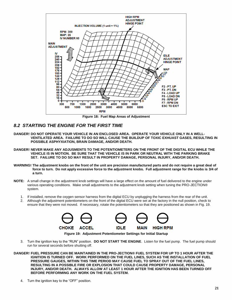
addition to operating the fast idle solenoid, the signal received from the engine coolant temperature sensor also provides information to the ECU relative to enriching or leaning out the fuel delivery. When the engine is cold, more fuel will be delivered and the fuel delivery is adjusted as the engine warms up. During cranking, the ECU begins receiving tach signals from the engine via the white wire in the system’s primary harness. At this time, power is applied to the fuel pump for continuous running and the fuel injectors are fired to deliver fuel to the engine. The appropriate amount of fuel is calculated by taking into account throttle position, engine coolant temperature, and an optional oxygen sensor feedback voltage. The throttle position sensor provides information relative to how far and how fast the throttle is being opened or closed. The oxygen sensor provides information on whether the engine is running rich or lean. Even though the oxygen sensor is hated, the ECU will continue to operate in an open loop mode for a short period of time after initial startup. This combined information is then used by the ECU to adjust the fuel delivery to the engine. In addition to the information provided to the ECU by the various sensors, the user is also able to adjust the fuel delivery through the use of the five adjustment knobs on the front of the ECU. Each of the adjustment knobs is factory set in a null (“0”) position. The user is able to adjust fuel delivery for (1) Idle, (2) Main, (3) High RPM, (4) Accelerator Pump, and (5) Choke settings. A detailed
description of each adjustment is given below. Refer to Figure 18 during the discussion of each of the adjustments. The fuel map is programmed into the digital ECU is comprised of 256 individual points. Each point has a throttle position and rpm value assigned to it. These values are used by the digital ECU to determine the appropriate fuel delivery when the system is in operation. During vehicle operation, the fast idle solenoid is also utilized to allow for a smoother deceleration. During deceleration, the fast idle solenoid is activated for a pre-determined period of time and prevents stalling, as would an idle air control motor. In addition to all of the aforementioned features, a “CLEAR FLOOD” mode has also been programmed into the ECU to aid in vehicle startup in case excessive
fuel has entered the intake manifold.
8.1.1 IDLE The idle adjustment knob allows the user to adjust the fuel delivery in the idle region of the fuel map 30% above or below the values that are set at the factory. This is accomplished by moving the lower part of the fuel map either up or down along a hinged horizontal line as indicated in Figure 18. Adjustments to the idle region of the fuel map are made AFTER the MAIN adjustment knob has been properly adjusted. Turning the knob clockwise increases the fuel delivery, while a counter-clockwise rotation decreases the amount of fuel delivered to the engine during idle.
8.1.2 MAIN The MAIN adjustment knob allows the user to adjust the fuel delivery of the entire fuel map 50% above or below the values set at the factory. Rotating the knob clockwise will raise the fuel map vertically, therefore increasing the fuel delivery for all points in the map. Rotating the knob counter-clockwise will lower the map vertically, therefore decreasing the fuel delivery for all points in the map. In tuning the system, the MAIN is the first value to be adjusted. All other adjustments are made AFTER the MAIN has been properly
set. 8.1.3 HIGH RPM The HIGH RPM adjustment knob allows the user to adjust the fuel delivery for engine speeds over 3000 rpm 50% above or below the values that are set at the factory. This is accomplished by moving the fuel map either up or down along a diagonal hinged line as indicated in Figure 18. Turning the adjustment knob clockwise increases the fuel delivery, while a counter-clockwise rotation decreases the amount of fuel delivered to the engine at high engine speeds.
8.1.4 ACCEL PUMP The ACCEL PUMP adjustment knob allows the user to adjust the addition of fuel for acceleration 50% above or below the value set at the factory. Rotating the adjustment knob clockwise results in additional fuel being added to the fuel enrichment set at the factory, while rotating the adjustment knob counter-clockwise will result in less fuel being added during acceleration. The proper adjustment is made while performing acceleration tests which are described later on in this section.
8.1.5 CHOKE The CHOKE adjustment knob allows the user to adjust the amount of fuel enrichment while the engine is warming up 20% above or below the value set at the factory. Rotating the adjustment knob clockwise will increase the amount of fuel added while the engine is warming up. Rotating the adjustment knob counter-clockwise will decrease the amount of fuel added while the engine is warming up. The CHOKE adjustment knob DOES NOT control eth length of time that the fast idle solenoid is on.
21
Figure 18: Fuel Map Areas of Adjustment
8.2 STARTING THE ENGINE FOR THE FIRST TIME DANGER! DO NOT OPERATE YOUR VEHICLE IN AN ENCLOSED AREA. OPERATE YOUR VEHICLE ONLY IN A WELL-
VENTILATED AREA. FAILURE TO DO SO WILL CAUSE THE BUILDUP OF TOXIC EXHUAST GASES, RESULTING IN POSSIBLE ASPHYXIATION, BRAIN DAMAGE, AND/OR DEATH.
DANGER! NEVER MAKE ANY ADJUSMENTS TO THE POTENTIOMETERS ON THE FRONT OF THE DIGITAL ECU WHILE THE
VEHICLE IS IN MOTION. BE SURE THAT THE VEHICLE IS IN PARK OR NEUTRAL WITH THE PARKING BRAKE SET. FAILURE TO DO SO MAY RESULT IN PROPERTY DAMAGE, PERSONAL INJURY, AND/OR DEATH.
WARNING! The adjustment knobs on the front of the unit are precision manufactured parts and do not require a great deal of
force to turn. Do not apply excessive force to the adjustment knobs. Full adjustment range for the knobs is 3/4 of a turn.
NOTE: A small change in the adjustment knob settings will have a large effect on the amount of fuel delivered to the engine under
various operating conditions. Make small adjustments to the adjustment knob setting when tuning the PRO-JECTION® system.
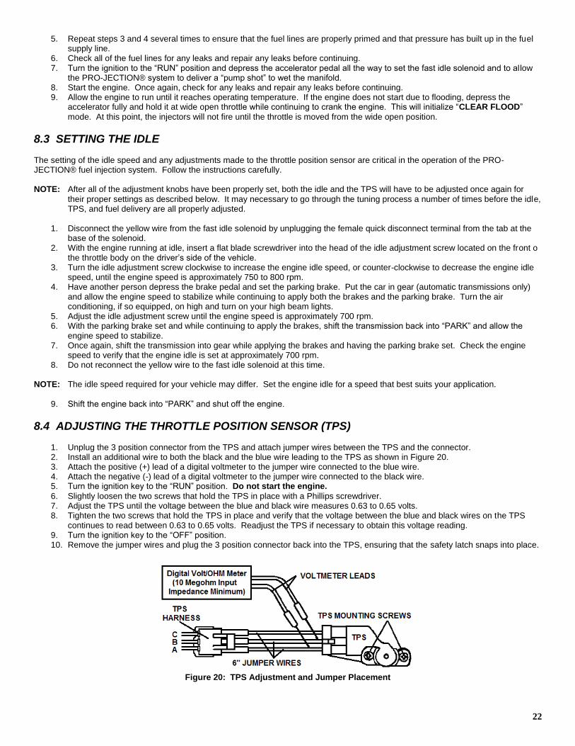
1. If installed, remove the oxygen sensor harness from the digital ECU by unplugging the harness from the rear of the unit. 2. Although the adjustment potentiometers on the front of the digital ECU were set at the factory in the null position, check to
ensure that they were not moved. If necessary, rotate the potentiometers so that they are positioned as shown in Fig. 19.
Figure 19: Adjustment Potentiometer Settings for Initial Startup
3. Turn the ignition key to the “RUN” position. DO NOT START THE ENGINE. Listen for the fuel pump. The fuel pump should
run for several seconds before shutting off. DANGER! FUEL PRESSURE CAN BE MAINTAINED IN THE PRO-JECTION® FUEL SYSTEM FOR UP TO 1 HOUR AFTER THE
IGNITION IS TURNED OFF. WORK PERFORMED ON THE FUEL LINES, SUCH AS THE INSTALLATION OF FUEL PRESSURE GAUGES, WITHIN THIS TIME PERIOD MAY CAUSE FUEL TO SPRAY OUT OF THE FUEL LINES, RESULTING IN A POSSIBLE FIRE OR EXPLOSION THAT COULD CAUSE PROPERTY DAMAGE, PERSONAL INJURY, AND/OR DEATH. ALWAYS ALLOW AT LEAST 1 HOUR AFTER THE IGNITION HAS BEEN TURNED OFF BEFORE PERFORMING ANY WORK ON THE FUEL SYSTEM.
4. Turn the ignition key to the “OFF” position.
22
5. Repeat steps 3 and 4 several times to ensure that the fuel lines are properly primed and that pressure has built up in the fuel supply line.
6. Check all of the fuel lines for any leaks and repair any leaks before continuing. 7. Turn the ignition to the “RUN” position and depress the accelerator pedal all the way to set the fast idle solenoid and to allow
the PRO-JECTION® system to deliver a “pump shot” to wet the manifold. 8. Start the engine. Once again, check for any leaks and repair any leaks before continuing. 9. Allow the engine to run until it reaches operating temperature. If the engine does not start due to flooding, depress the
accelerator fully and hold it at wide open throttle while continuing to crank the engine. This will initialize “CLEAR FLOOD”
mode. At this point, the injectors will not fire until the throttle is moved from the wide open position.
8.3 SETTING THE IDLE The setting of the idle speed and any adjustments made to the throttle position sensor are critical in the operation of the PRO-JECTION® fuel injection system. Follow the instructions carefully. NOTE: After all of the adjustment knobs have been properly set, both the idle and the TPS will have to be adjusted once again for
their proper settings as described below. It may necessary to go through the tuning process a number of times before the idle, TPS, and fuel delivery are all properly adjusted.
1. Disconnect the yellow wire from the fast idle solenoid by unplugging the female quick disconnect terminal from the tab at the
base of the solenoid. 2. With the engine running at idle, insert a flat blade screwdriver into the head of the idle adjustment screw located on the front o
the throttle body on the driver’s side of the vehicle. 3. Turn the idle adjustment screw clockwise to increase the engine idle speed, or counter-clockwise to decrease the engine idle
speed, until the engine speed is approximately 750 to 800 rpm. 4. Have another person depress the brake pedal and set the parking brake. Put the car in gear (automatic transmissions only)
and allow the engine speed to stabilize while continuing to apply both the brakes and the parking brake. Turn the air conditioning, if so equipped, on high and turn on your high beam lights.
5. Adjust the idle adjustment screw until the engine speed is approximately 700 rpm. 6. With the parking brake set and while continuing to apply the brakes, shift the transmission back into “PARK” and allow the
engine speed to stabilize. 7. Once again, shift the transmission into gear while applying the brakes and having the parking brake set. Check the engine
speed to verify that the engine idle is set at approximately 700 rpm. 8. Do not reconnect the yellow wire to the fast idle solenoid at this time.
NOTE: The idle speed required for your vehicle may differ. Set the engine idle for a speed that best suits your application.
9. Shift the engine back into “PARK” and shut off the engine.
8.4 ADJUSTING THE THROTTLE POSITION SENSOR (TPS)
1. Unplug the 3 position connector from the TPS and attach jumper wires between the TPS and the connector. 2. Install an additional wire to both the black and the blue wire leading to the TPS as shown in Figure 20. 3. Attach the positive (+) lead of a digital voltmeter to the jumper wire connected to the blue wire. 4. Attach the negative (-) lead of a digital voltmeter to the jumper wire connected to the black wire. 5. Turn the ignition key to the “RUN” position. Do not start the engine.
6. Slightly loosen the two screws that hold the TPS in place with a Phillips screwdriver. 7. Adjust the TPS until the voltage between the blue and black wire measures 0.63 to 0.65 volts. 8. Tighten the two screws that hold the TPS in place and verify that the voltage between the blue and black wires on the TPS
continues to read between 0.63 to 0.65 volts. Readjust the TPS if necessary to obtain this voltage reading. 9. Turn the ignition key to the “OFF” position. 10. Remove the jumper wires and plug the 3 position connector back into the TPS, ensuring that the safety latch snaps into place.
Figure 20: TPS Adjustment and Jumper Placement
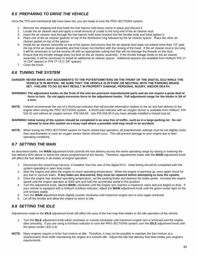
23
8.5 PREPARING TO DRIVE THE VEHICLE Once the TPS and mechanical idle have been set, you are ready to tune the PRO-JECTION® system.
1. Remove the shipping bolt that holds the fuel injector hold down clamp in place and discard it. 2. Locate the air cleaner stud and apply a small amount of Loctite to the long end of the air cleaner stud. 3. Insert the air cleaner stud through the fuel injector hold down bracket into the throttle body and hand tighten it. 4. Place one of the air cleaner gaskets on top of the distribution ring followed by the air cleaner spacer. Place the other air
cleaner gasket on top of the spacer. 5. Install the air cleaner assembly on top of the spacer and ensure that the air cleaner stud does not extend more than 1/2” past
the top of the air cleaner assembly and that it does not interfere with the closing of the hood. If the air cleaner stud is too long, it will be necessary to cut the excess off with an appropriate cutting tool that will not damage the threads on the stud.
6. Ensure that the throttle linkage does not bind on the air cleaner assembly. If the throttle linkage binds on the air cleaner assembly, it will be necessary to install an additional air cleaner spacer. Additional spacers are available from Holley® P/N 17-14 (3/4” spacer) or P/N 17-13 (1 3/8” spacer).
7. Close the hood.
8.6 TUNING THE SYSTEM DANGER! NEVER MAKE ANY ADJUSMENTS TO THE POTENTIOMETERS ON THE FRONT OF THE DIGITAL ECU WHILE THE
VEHICLE IS IN MOTION. BE SURE THAT THE VEHICLE IS IN PARK OR NEUTRAL WITH THE PARKING BRAKE SET. FAILURE TO DO SO MAY RESULT IN PROPERTY DAMAGE, PERSONAL INJURY, AND/OR DEATH.
WARNING! The adjustment knobs on the front of the unit are precision manufactured parts and do not require a great deal of
force to turn. Do not apply excessive force to the adjustment knobs. Full adjustment range for the knobs is 3/4 of a turn.
NOTE: Holley® recommends the use of a Rich/Lean indicator that will provide information relative to the air and fuel delivery to the
engine when tuning the PRO-JECTION® system. A Rich/Lean indicator with an oxygen sensor is available from Holley®, P/N 534-51 and without an oxygen sensor, P/N 534-50. Use P/N 534-50 if you have already installed a closed loop kit.
WARNING! Initial tuning of the system should be completed in an area free of traffic, such as in a large parking lot. Do not
attempt to tune this system on a busy road where a possible stall may result in an accident. NOTE: When tuning the PRO-JECTION® system for future closed loop operation, all potentiometer settings must be set slightly richer
than stoichiometric in case an oxygen sensor failure should occur. This will prevent damage to your engine due to lean operating conditions.
8.7 SETTING THE MAIN As described earlier, the MAIN adjustment knob controls the fuel delivery across the entire operating range by raising or lowering the fuel delivery 50% above or below the values programmed at the factory. Therefore, adjustments made with the MAIN adjustment knob
will affect the fuel delivery in all modes of engine operation.
1. Disconnect the closed loop harness, if installed, from the rear of the digital ECU. Initial timing should be completed with the system operating in open loop mode.
2. Start the engine and allow the engine to reach operating temperature. While the engine is warming up, once again check for any fuel or vacuum leaks. If any leaks are discovered, they must be repaired before attempting to tune the system.
3. Once the engine has reached operating temperature, set the parking brake and depress the brake pedal. Increase the engine speed until the engine operates at 3000 rpm and hold the accelerator pedal in this position.
4. Turn the adjustment knob, labeled MAIN, clockwise until the engine rpm reaches a maximum value and just begins to drop. If your vehicle is equipped with a Holley® rich/lean indicator, adjust the MAIN adjustment knob until the green center light on the
unit remains stable. 5. Turn the MAIN adjustment knob slightly counter-clockwise until maximum engine rpm is once again achieved.
6. Let off the throttle and allow the engine to return to idle.
8.8 SETTING THE IDLE Adjustments made to the IDLE adjustment knob will affect the area of the fuel map that relates to the idle operation of the vehicle.
1. Turn the IDLE adjustment knob either clockwise or counter-clockwise until maximum engine rpm is achieved and the engine
idles smoothly. If you are using a rich/lean indicator to tune the PRO-JECTION® system, turn the IDLE adjustment knob until
the green center LED is lit. NOTE: Many engines require a richer fuel mixture at idle. Therefore, it may not be possible to maintain the fuel mixture at a
stoichiometric level while maintaining the engine at a smooth idle. Adjust the idle fuel delivery that best meets your engine’s requirements.
24
2. Turn on the air conditioner and your high beam lights. Set the parking brake and depress the brake pedal. Shift the
transmission into gear. 3. Adjust the IDLE adjustment knob as described in Step 1. If you are unable to adjust the IDLE adjustment knob to achieve a
proper idle, it may be necessary to once again adjust the curb idle adjustment screw located on the driver’s side front of the throttle body to a higher setting.
NOTE: If you change the setting of the idle adjustment screw, it will be necessary to once again adjust the TPS to the proper idle
setting. Once the TPS and idle have been adjusted, it will also be necessary to adjust the MAIN adjustment knob as
described above.
4. Once the idle has been properly set, turn off the air conditioner and high beam lights. Shift the transmission back into neutral or into PARK.
8.9 SETTING THE ACCEL The ACCEL adjustment knob controls the amount of fuel that is added to the engine when accelerating. Adjustments made here allow
for a quick, crisp response during acceleration. WARNING! Do not attempt to perform acceleration tests on a busy road or highway. Complete this stage of the tuning
process in an area free of traffic, such as in a large parking lot. Failure to do so may result in property damage, personal injury, and/or death.
1. Shift the transmission into gear and slowly accelerate the vehicle to approximately 20 mph. 2. Quickly depress the accelerator pedal and note the performance of the engine. If the engine bogs (falls flat) and black smoke
comes out of the exhaust, the ACCEL adjustment is set too high. If the engine bogs and no black smoke comes out of the exhaust, the ACCEL adjustment is set too low.
3. Adjust the ACCEL adjustment knob accordingly and continue performing acceleration tests until you achieve a quick, crisp
response during acceleration and no black smoke comes from the exhaust.
8.10 SETTING THE HIGH RPM The HIGH RPM adjustment knob changes the fuel delivery to the engine at engine speeds over 3000 rpm. DANGER! NEVER MAKE ANY ADJUSMENTS TO THE POTENTIOMETERS ON THE FRONT OF THE DIGITAL ECU WHILE THE
VEHICLE IS IN MOTION. BE SURE THAT THE VEHICLE IS IN PARK OR NEUTRAL WITH THE PARKING BRAKE SET. FAILURE TO DO SO MAY RESULT IN PROPERTY DAMAGE, PERSONAL INJURY, AND/OR DEATH.
WARNING! Do not attempt to perform acceleration tests on a busy road or highway. Complete this stage of the tuning
process in an area free of traffic, such as a large parking lot. Failure to do so may result in property damage, personal injury, and/or death.
NOTE: To properly set the HIGH RPM setting, it will be necessary to operate your engine at a steady speed while determining the
proper fuel delivery.
1. Shift the transmission into second gear or the automatic transmission equivalent. 2. Begin to smoothly accelerate the vehicle until the engine speed is above 3000 RPM. Note the performance of the engine. 3. Bring the vehicle to a complete stop and set the parking brake. Increase or decrease the amount of fuel delivered during high
engine speeds by turning the HIGH RPM adjustment knob either clockwise or counter-clockwise. If your vehicle is equipped with a Rich/Lean indicator, adjust the HIGH RPM adjustment knob until the meter indicates a stoichiometric fuel mixture at
high engine speeds. 4. Repeat steps 1, 2, and 3, until your engine operates smoothly at high engine speeds.
8.11 SETTING THE CHOKE The CHOKE adjustment knob controls the fuel delivery to the engine during a cold start. The CHOKE adjustment knob DOES NOT control the “ON” time for the fast idle solenoid. Adjustment to the CHOKE should be made after the engine has cooled down
completely.
1. After the engine has cooled down completely (Holley® recommends allowing the engine to sit overnight), start the engine. 2. Immediately after starting the engine, shift the transmission into gear and accelerate slowly. 3. Turn the CHOKE adjustment knob to achieve a clean drive-away from a cold start. Several cold starts will be necessary to
zero in on the proper CHOKE setting.
25
8.12 SETTING THE FAST IDLE SOLENOID
1. Start the engine and allow it to reach operating temperature. 2. Connect a temporary jumper wire between the positive terminal on the battery and the tab at the base of the fast idle solenoid.
This will extend the plunger on the fast idle solenoid. 3. Adjust the plunger outward by turning the hex head on the plunger with a 1/2” open end wrench until the engine speed is
approximately 1800 rpm. 4. Remove the temporary jumper wire between the fast idle solenoid and the positive terminal on the battery. 5. Reconnect the yellow wire to the fast idle solenoid.
9.0 SYSTEM MAINTENANCE The PRO-JECTION® system is virtually maintenance free. To ensure performance and reliability, periodically check all fuel lines for leaks and replace them as needed. Also ensure that all electrical connections remain secure and that all wires are routed away from any direct sources of heat, such as the exhaust system, and any moving parts. If a decrease in system performance is noticed, a dirty or clogged fuel filter may be the cause. Holley® recommends that both fuel filters installed with the PRO-JECTION® system be changed every 20,000 miles of normal operation. These filters are non-serviceable and must be replaced. Contact your local parts dealer for replacement fuel filters.
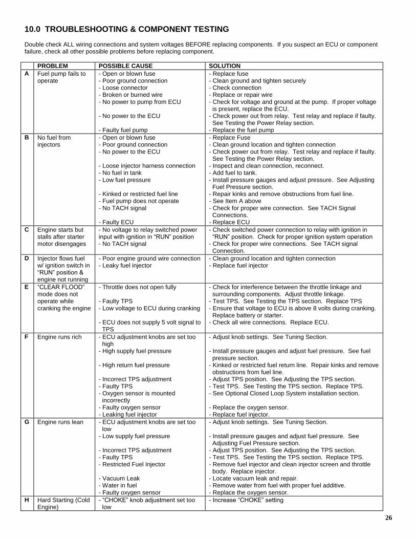
26
10.0 TROUBLESHOOTING & COMPONENT TESTING Double check ALL wiring connections and system voltages BEFORE replacing components. If you suspect an ECU or component failure, check all other possible problems before replacing component.
PROBLEM POSSIBLE CAUSE SOLUTION
A Fuel pump fails to operate
- Open or blown fuse - Poor ground connection - Loose connector - Broken or burned wire - No power to pump from ECU - No power to the ECU - Faulty fuel pump
- Replace fuse - Clean ground and tighten securely - Check connection - Replace or repair wire - Check for voltage and ground at the pump. If proper voltage is present, replace the ECU. - Check power out from relay. Test relay and replace if faulty. See Testing the Power Relay section. - Replace the fuel pump
B No fuel from injectors
- Open or blown fuse - Poor ground connection - No power to the ECU - Loose injector harness connection - No fuel in tank - Low fuel pressure - Kinked or restricted fuel line - Fuel pump does not operate - No TACH signal - Faulty ECU
- Replace Fuse - Clean ground location and tighten connection - Check power out from relay. Test relay and replace if faulty. See Testing the Power Relay section. - Inspect and clean connection, reconnect. - Add fuel to tank. - Install pressure gauges and adjust pressure. See Adjusting Fuel Pressure section. - Repair kinks and remove obstructions from fuel line. - See Item A above - Check for proper wire connection. See TACH Signal Connections. - Replace ECU
C Engine starts but stalls after starter motor disengages
- No voltage to relay switched power input with ignition in “RUN” position - No TACH signal
- Check switched power connection to relay with ignition in “RUN” position. Check for proper ignition system operation - Check for proper wire connections. See TACH signal Connection.
D Injector flows fuel w/ ignition switch in “RUN” position & engine not running
- Poor engine ground wire connection - Leaky fuel injector
- Clean ground location and tighten connection - Replace fuel injector
E “CLEAR FLOOD” mode does not operate while cranking the engine
- Throttle does not open fully - Faulty TPS - Low voltage to ECU during cranking - ECU does not supply 5 volt signal to TPS
- Check for interference between the throttle linkage and surrounding components. Adjust throttle linkage. - Test TPS. See Testing the TPS section. Replace TPS - Ensure that voltage to ECU is above 8 volts during cranking. Replace battery or starter. - Check all wire connections. Replace ECU.
F Engine runs rich - ECU adjustment knobs are set too high - High supply fuel pressure - High return fuel pressure - Incorrect TPS adjustment - Faulty TPS - Oxygen sensor is mounted incorrectly - Faulty oxygen sensor - Leaking fuel injector
- Adjust knob settings. See Tuning Section. - Install pressure gauges and adjust fuel pressure. See fuel pressure section. - Kinked or restricted fuel return line. Repair kinks and remove obstructions from fuel line. - Adjust TPS position. See Adjusting the TPS section. - Test TPS. See Testing the TPS section. Replace TPS. - See Optional Closed Loop System installation section. - Replace the oxygen sensor. - Replace fuel injector.
G Engine runs lean - ECU adjustment knobs are set too low - Low supply fuel pressure - Incorrect TPS adjustment - Faulty TPS - Restricted Fuel Injector - Vacuum Leak - Water in fuel - Faulty oxygen sensor
- Adjust knob settings. See Tuning Section. - Install pressure gauges and adjust fuel pressure. See Adjusting Fuel Pressure section. - Adjust TPS position. See Adjusting the TPS section. - Test TPS. See Testing the TPS section. Replace TPS. - Remove fuel injector and clean injector screen and throttle body. Replace injector. - Locate vacuum leak and repair. - Remove water from fuel with proper fuel additive. - Replace the oxygen sensor.
H Hard Starting (Cold Engine)
- “CHOKE” knob adjustment set too low
- Increase “CHOKE” setting
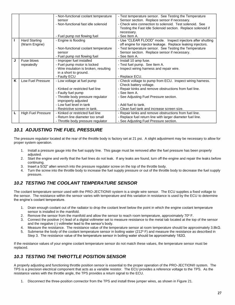
27
- Non-functional coolant temperature sensor - Non-functional fast idle solenoid - Fuel pump not flowing fuel
- Test temperature sensor. See Testing the Temperature Sensor section. Replace sensor if necessary. - Check wire connection to solenoid. Test solenoid. See Testing the Fast Idle Solenoid section. Replace solenoid if necessary. - See Item A.
I Hard Starting (Warm Engine)
- Engine is flooding - Non-functional coolant temperature sensor - Fuel pump not flowing fuel
- Use “CLEAR FLOOD” mode. Inspect injectors after shutting off engine for injector leakage. Replace leaking injectors. - Test temperature sensor. See Testing the Temperature Sensor section. Replace sensor if necessary. - See Item A.
J Fuse blows repeatedly
- Improper fuel installed - Fuel pump motor is locked - Wire insulation is broken, resulting in a short to ground. - Faulty ECU
- Install 10 amp fuse. - Test fuel pump. See Item A. - Inspect wiring harness and repair wire. - Replace ECU.
K Low Fuel Pressure - Low voltage at fuel pump - Kinked or restricted fuel line - Faulty fuel pump - Throttle body pressure regulator improperly adjusted - Low fuel level in tank - Restrictive screen in tank.
- Check voltage to pump from ECU. Inspect wiring harness. Check battery voltage. - Repair kinks and remove obstructions from fuel line. - See Item A. - See Adjusting Fuel Pressure section. - Add fuel to tank. - Clean fuel tank and increase screen size.
L High Fuel Pressure - Kinked or restricted fuel line - Return line diameter too small - Throttle body pressure regulator
- Repair kinks and remove obstructions from fuel line. - Replace fuel return line with larger diameter fuel line. - See Adjusting Fuel Pressure section.
10.1 ADJUSTING THE FUEL PRESSURE The pressure regulator located at the rear of the throttle body is factory set at 21 psi. A slight adjustment may be necessary to allow for proper system operation.
1. Install a pressure gauge into the fuel supply line. This gauge must be removed after the fuel pressure has been properly adjusted.
2. Start the engine and verify that the fuel lines do not leak. If any leaks are found, turn off the engine and repair the leaks before continuing.
3. Insert a 5/32” allen wrench into the pressure regulator screw on the top of the throttle body. 4. Turn the screw into the throttle body to increase the fuel supply pressure or out of the throttle body to decrease the fuel supply
pressure.
10.2 TESTING THE COOLANT TEMPERATURE SENSOR The coolant temperature sensor used with the PRO-JECTION® system is a single wire sensor. The ECU supplies a fixed voltage to the sensor. The resistance within the sensor varies with temperature and this variation in resistance is used by the ECU to determine the engine’s coolant temperature.
1. Drain enough coolant out of the radiator to drop the coolant level below the point in which the engine coolant temperature sensor is installed in the manifold.
2. Remove the sensor from the manifold and allow the sensor to reach room temperature, approximately 70º F. 3. Connect the positive (+) lead of a digital voltmeter set to measure resistance to the metal tab located at the top of the sensor
and the negative (-) voltmeter lead to the sensor’s body. 4. Measure the resistance. The resistance value of the temperature sensor at room temperature should be approximately 3.8kΩ. 5. Submerse the body of the coolant temperature sensor in boiling water (212º F) and measure the resistance as described in
Step 3. The resistance value of the temperature sensor in boiling water should be approximately 182Ω. If the resistance values of your engine coolant temperature sensor do not match these values, the temperature sensor must be replaced.
10.3 TESTING THE THROTTLE POSITION SENSOR A properly adjusting and functioning throttle position sensor is essential to the proper operation of the PRO-JECTION® system. The TPS is a precision electrical component that acts as a variable resistor. The ECU provides a reference voltage to the TPS. As the resistance varies with the throttle angle, the TPS provides a return signal to the ECU.
1. Disconnect the three-position connector from the TPS and install three jumper wires, as shown in Figure 21.
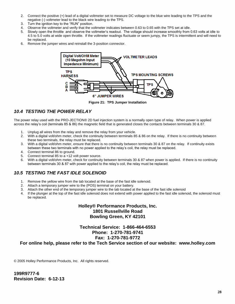
28
2. Connect the positive (+) lead of a digital voltmeter set to measure DC voltage to the blue wire leading to the TPS and the negative (-) voltmeter lead to the black wire leading to the TPS.
3. Turn the ignition key to the “RUN” position. 4. Observe the voltmeter and verify that the voltmeter indicates between 0.63 to 0.65 with the TPS set at idle. 5. Slowly open the throttle and observe the voltmeter’s readout. The voltage should increase smoothly from 0.63 volts at idle to
4.5 to 5.0 volts at wide open throttle. If the voltmeter readings fluctuate or seem jumpy, the TPS is intermittent and will need to be replaced.
6. Remove the jumper wires and reinstall the 3-position connector.
Figure 21: TPS Jumper Installation
10.4 TESTING THE POWER RELAY The power relay used with the PRO-JECTION® 2D fuel injection system is a normally open type of relay. When power is applied across the relay’s coil (terminals 85 & 86) the magnetic field that is generated closes the contacts between terminals 30 & 87.
1. Unplug all wires from the relay and remove the relay from your vehicle. 2. With a digital volt/ohm meter, check the continuity between terminals 85 & 86 on the relay. If there is no continuity between
these two terminals, the relay must be replaced. 3. With a digital volt/ohm meter, ensure that there is no continuity between terminals 30 & 87 on the relay. If continuity exists
between these two terminals with no power applied to the relay’s coil, the relay must be replaced. 4. Connect terminal 86 to ground. 5. Connect terminal 85 to a +12 volt power source. 6. With a digital volt/ohm meter, check for continuity between terminals 30 & 87 when power is applied. If there is no continuity
between terminals 30 & 87 with power applied to the relay’s coil, the relay must be replaced.
10.5 TESTING THE FAST IDLE SOLENOID
1. Remove the yellow wire from the tab located at the base of the fast idle solenoid. 2. Attach a temporary jumper wire to the (POS) terminal on your battery. 3. Attach the other end of the temporary jumper wire to the tab located at the base of the fast idle solenoid 4. If the plunger at the top of the fast idle solenoid does not extend with power applied to the fast idle solenoid, the solenoid must
be replaced.
Holley® Performance Products, Inc. 1801 Russellville Road
Bowling Green, KY 42101
Technical Service: 1-866-464-6553 Phone: 1-270-781-9741
Fax: 1-270-781-9772 For online help, please refer to the Tech Service section of our website: www.holley.com
© 2005 Holley Performance Products, Inc. All rights reserved.
199R9777-6 Revision Date: 6-12-13