private cars c5-synergie 2002c5club.neerden.nl/c5/pdf/en_us_t2_2002.pdf · private cars c5-synergie...
TRANSCRIPT

PRIVATE CARS
C5-SYNERGIE
PR
IVA
TE
CA
RS
CAR 050011Volume 2
2002AC.QCAV/MTD
Méthodes Techniques Documentation
’’The intellectual property rights relating to the technical information contained in this document belongexclusively to the manufacturer. Reproduction, translation or distribution in whole or in part withoutprior written authorisation from the manufacturer is forbidden.‘‘
«The technical information contained in this document is intended for the exclusive use of the trained personnel of themotor vehicle repair trade. In some instances, this information could concern the security and safety of the vehicle. Theinformation is to be used by the professional vehicle repairers for whom it is intended and they alone would assume fullresponsibility to the exclusion of that of the manufacturer».«The technical information appearing in this brochure is subject to updating as the characteristics of each model in therange evolve. Motor vehicle repairers are invited to contact the CITROËN network periodically for further information andto obtain any possible updates».
2002
PRESENTATION
THIS HANDBOOK summarises the characteristics, adjustments, checks and special features of CITROEN vehicles, not including COMMERCIALvehicles for which there exists a separate handbook.
The handbook is divided into nine groups representing the main functions :
GENERAL - ENGINE - INJECTION - IGNITION - CLUTCH, GEARBOX, DRIVESHAFTS - AXLES, SUSPENSION, STEERING - BRAKES - ELECTRICAL -AIR CONDITIONING.
In each section, the vehicles are dealt with in the following order : C5 - SYNERGIE and all models where applicable.
The information given in this handbook is based on vehicles marketed in EUROPE.

IMPORTANT
If you find that this handbook does not always meet your requirements, we invite you to send us your suggestions which we will take into accountwhen preparing future publications. For example :
– INSUFFICIENT INFORMATION– SUPERFLUOUS INFORMATION– NEED FOR MORE DETAILS
Please send your comments and suggestions to :
CITROEN U.K. Ltd.221, Bath Road,SLOUGH,SL1 4BA. U.K.

1
GE
NE
RA
L
IDENTIFICATION OF VEHICLES
E1APO8RD
(A) Chassis stamp (cold stamp on bodywork).
(B) Manufacturer’s data plate.(under the rear bench seat)
(C) A-S / RP No. and RP paint code(label on front pillar close to driver’s door).
(D) Inflation pressures and tyre references.(label on front pillar close to driver’s door)
(E) Serial no. on bodywork.
(F) Gearbox reference – Factory serial no.
(G) Engine legislation type – Factory serial no

GE
NE
RA
L
DC 6FZB DC 6FZC/IF DC 6FZE DC RFNC/IF DC RFNB DC RFNE
6FZ RFN
1749 1997
7 8 9
BE4/5 AL4 BE4/5 AL4
20 DL 29 20 TP 44 20 BL 30 20 TP 42
Emission standard L4 L5 L4 L5 L4 L5
Type code
Engine type
Cubic capacity (cc)
Fiscal rating (hp)
Gearbox type
Gearbox ident. plate
2
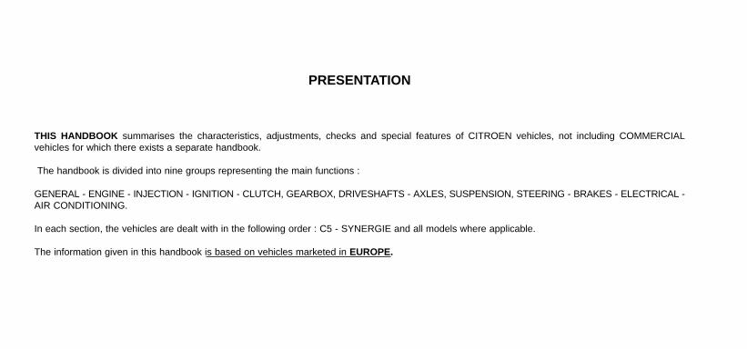
C5 - All Types IDENTIFICATION OF VEHICLES
Petrol saloons
X-SX
1.8i 16V
X-SX-Exclusive
2.0i 16V
AutomaticAutomatic
3
GE
NE
RA
L
L4 L5
DC RLZB DC XFXC/IF DC XFXF/IF
RLZ XFX
1997 2946
8 13 14
BE4/5 ML/5C ML/5T 4 HP 20
20 DL31 20 LM 21 20 LE 95 20 HZ 13
C5 - All TypesIDENTIFICATION OF VEHICLES
Petrol saloons
2.0 HPi 30.i 24V V6
Exclusive
Automatic
Emission standard
Type code
Engine type
Cubic capacity (cc)
Fiscal rating (hp)
Gearbox type
Gearbox ident. plate

4
GE
NE
RA
L
Emission standard L4
Type code DC RHYB DC RHSB DC RHSE DC RHZB DC RHZE
Engine type RHY RHS RHZ
Cubic capacity (cc) 1997
Fiscal rating (hp) 6 7 6 7
Gearbox type BE4/5 ML/5C ML/5T (*) AL4 ML/5C ML/5T AL4
Gearbox ident. plate 20 DL 32 20 LM 18 20 LE 94 20 TP 43 20 LM 18 20 LE 94 20 TP 43
C5 - All Types IDENTIFICATION OF VEHICLES
Diesel saloons
2.0 HDi
X X-Exclusive
Automatic Automatic
(*) FAP = Particle filter

5
GE
NE
RA
L
Automatic
Emission standard L4
Type code DC 4HXB DC 4HXE
Engine type 4HX
Cubic capacity (cc) 2179
Fiscal rating (hp) 8
Gearbox type ML/5C ML/5T 4 HP 20
Gearbox ident. plate 20 LM 17 20 LE 96 20 HZ 20
IDENTIFICATION OF VEHICLES
Diesel saloons
2.2 HDi
SX-Exclusive
C5 - All Types
6
GE
NE
RA
L
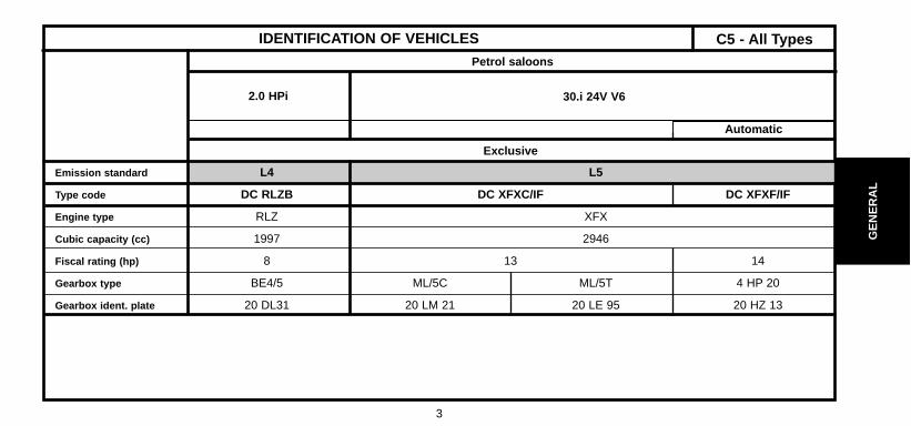
Emission standard L4 L5 L4 L5
Type code DE 6FZC/IF DE 6FZB DE RFNC/IF DE RFNE DE RLZB DE XFX/IF DE XFXF/IF
Engine type 6FZ RFN RLZ XFX
Cubic capacity (cc) 1749 1997 2946
Fiscal rating (hp) 7 9 8 13 14
Gearbox type BE4/5 AL4 BE4/5 ML/5C ML/5T 4 HP 20
Gearbox ident. plate 20 DL 29 20 DL 30 ? 20 DL 31 20 LM 21 20 LE 95 20 HZ 13
IDENTIFICATION OF VEHICLES
Petrol estates
3.0i 24V V62.0 HPi2.0i 16V1.8i 16V
ExclusiveSX
ExclusiveX-SX
AutomaticAutomatic
C5 - All Types

7
GE
NE
RA
L
Emission standard L4
Type code DE RHYB DE RHSB DE RHSE DE RHZB DE RHZE
Engine type RHY RHS RHZ
Cubic capacity (cc) 1997
Fiscal rating (hp) 6 7 6 7
Gearbox type BE4/5 ML/5C ML/5T AL4 ML/5C ML/5T AL4
Gearbox ident. plate 20 DL 32 20 LM 18 20 LE 94 (*) 20 TP 43 (*) 20 LM 18 20 LE 94 20 TP 48 (*)
C5 - All TypesIDENTIFICATION OF VEHICLES
Diesel estates
2.0 HDi
X X-Exclusive
Automatic Automatic
(*) FAP = Particle filter

8
GE
NE
RA
L
Automatic
Emission standard L4
Type code DE 4HXB DE 4HXE
Engine type 4HX
Cubic capacity (cc) 2179
Fiscal rating (hp) 8
Gearbox type ML/5C ML/5T 4 HP 20
Gearbox ident. plate 20 LM 17 20 LE 96 20 HZ 20
IDENTIFICATION OF VEHICLES
Diesel estates
2.2 HDi
SX-Exclusive
C5 - All Types

9
GE
NE
RA
L
IDENTIFICATION OF VEHICLES
1 Manufacturer’s cold stamp
2 R.P. organisation No.
3 Paint code
4 01/02/99 # Label :- Tyre pressures.- R.P. Organisation No.- Paint code.
5 Gearbox ident.
6 Engine plate
7 Manufacturer’s plate
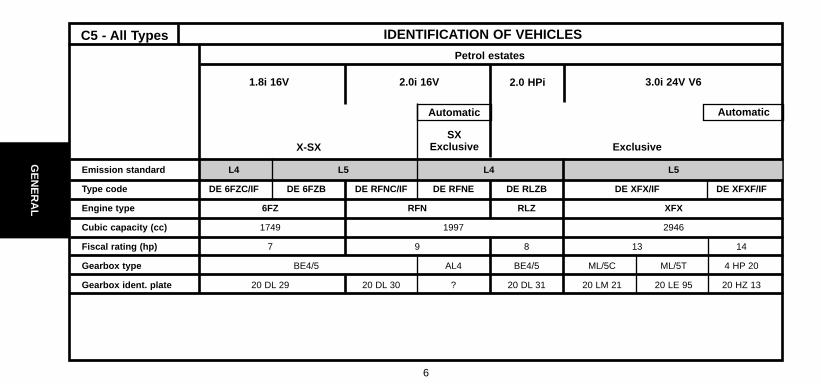
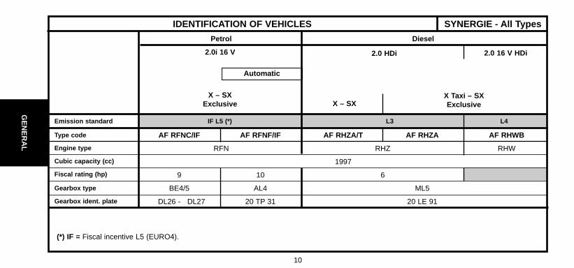
SYNERGIE - All Types
E1AP07GD
10
GE
NE
RA
L
Emission standard IF L5 (*) L3 L4
Type code
Engine type
Cubic capacity (cc)
Fiscal rating (hp)
Gearbox type
Gearbox ident. plate
AF RFNC/IF AF RFNF/IF AF RHZA/T AF RHZA AF RHWB
RFN RHZ RHW
1997
9 10 6
BE4/5 AL4 ML5
DL26 - DL27 20 TP 31 20 LE 91
IDENTIFICATION OF VEHICLES SYNERGIE - All Types
2.0 16 V HDi2.0 HDi
X – SXX Taxi – SXExclusive
2.0i 16 V
X – SXExclusive
DieselPetrol
Automatic
(*) IF = Fiscal incentive L5 (EURO4).

11
GE
NE
RA
L
CAPACITIES
Draining method.
The oil capacities are defined according to the following methods.
1) - Vehicle on level surface (in high position, if equipped with hydropneumatic suspension).
2) - Engine warm (oil temperature 80°C).
3) - Draining of the oil sump + removal of the cartridge (duration of draining + dripping = 15 mm ).
4) - Refit plug + cartridge.
5) - Engine filling.
6) - Engine starting (allowing the cartridge to be filled).
7) - Engine stopped (stationary for 5 mm ).
ESSENTIAL : Systematically check the oil level using the oil dipstick.
ALL TYPES

12
C5 - All Types
GE
NE
RA
L
Engine type
Engine with filter change
Between Min. and Max.
5-speed gearbox
Automatic gearbox
After oil change
Braking circuit
Hydraulic circuit
Cooling system
Fuel tank capacity
CAPACITIES (in litres)
Petrol
C5
(*) = With automatic gearboxESSENTIAL : Systematically check the oil level using the oil dipstick
1.8i 16V 2.0i 16V 3.0i V6
Automatic Automatic Automatic
6FZ RFN RLZ XFX
4.25 5.25
1.7 2
1.8 1.8 1.8
6 6 8.3
3 3 5.3
4.3
8.8 – 9.3 (*) 8.8 14
66
2.0 HPi

13
GE
NE
RA
L
Engine type
Engine with filter change
Between Min. and Max.
5-speed gearbox
Automatic gearbox
After oil change
Braking circuit
Hydraulic circuit
Cooling system
Fuel tank capacity
CAPACITIES (in litres)
Diesel
C5
(1) = With air conditioning.ESSENTIAL : Systematically check the oil level using the oil dipstick.
2.0 HDi 2.2 HDi
Automatic Automatic Automatic
RHY RHS RHZ 4HX
4.75 4.5 (1) 4.75
1.5 1.7 (1) 1.5
1.8 1.8 1.8
8.3 - 6 (1) 8.3 - 6 (1) 8.3
5.3 – 3 (1) 5.3 – 3 (1) 5.3
4.3
10.7 – 11.7 (With additional heating)
68
C5 - All Types

14
GE
NE
RA
L
RFN RHZ RHW
21°
4.25 4.5 4.75
1.7 1.4 1.9
1.8 1.8
8
3
Without ABS : 0.47 - With ABS : 0.52
7 8.5
80 80
CAPACITIES (in litres)SYNERGIE - All Types
Engine type
Engine angle
Engine with filter change
Between Min. and Max.
5-speed gearbox
Automatic gearbox
After oil change
Hydraulic or brake circuit
Cooling system
Fuel tank capacity
Synergie
Petrol Diesel
2.0i 16V 2.0 HDi 2.0 HDi 16V
(1) With air conditioning. - ESSENTIAL : Systematically check the oil level using the oil dipstick.
Automatic

15
GE
NE
RA
L
ALL TYPESLUBRICANTS - TOTAL recommended oils
S.A.E. Norm - Table for selection of engine oil grade
E4AP006D

16
GE
NE
RA
L
ALL TYPES
Factory evolutions in 2001 model year
CITROËN engines are lubricated at the factory with TOTAL oil ofgrade S.A.E.5W-30.TOTAL oil of grade S.A.E.5W-30 allows improved fuel economies(approx 2.5%).
Features of CITROËN C5 :2.0 and 2.2 HDi engines have a particle filter.The maintenance interval for normal operationis 30,000 km (20,000 miles) for petrol engines.
WARNING : HDi engines are high technology engines whichimperatively require use of quality SYNTHETIC OILS : TOTALACTIVA or TOTAL QUARTZ 5W40.To maintain engine performances, all countries in Europeshould observe this requirement.
NOTE : Only PORTUGAL and GREECE may use 10W40 semi-synthetic oil.
ESSENTIAL : For all vehicles with a 30,000 km (20,000 miles)maintenance interval, use exclusively TOTAL ACTIVA/QUARTZ7000 or 9000 or any other oils offering identical specifications tothese.These oils offer specifications that are superior to those definedby norms ACEA A3/98 or API SJ.Failing this, it is essential to adhere to the maintenance pro-grammes covering severe operating conditions.
5W30 cannot be used in the following engines:XU10J4RS : XSARA VTS 2.0i 16V (3 doors).SOFIM : RELAY 2.8 D and 2.8 TD.1580 SPI : DISPATCH 1.6i.2.0 and 2.2 HDi engines equipped with particle filter.
WARNING : CITROËN engines prior to model year 2000 do nothave to be lubricated with oils adhering to the norms ACEA A1-98/B1-98 and API SJ/CF EC.
LUBRICANTS - TOTAL recommended oils
17
GE
NE
RA
L
LUBRICANTS - TOTAL recommended oils
Selection of engine oil grades recommended for climatic conditions in countries of distribution
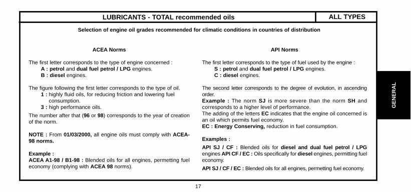
ACEA Norms
The first letter corresponds to the type of engine concerned : A : petrol and dual fuel petrol / LPG engines.B : diesel engines.
The figure following the first letter corresponds to the type of oil.1 : highly fluid oils, for reducing friction and lowering fuel
consumption.3 : high performance oils.
The number after that (96 or 98) corresponds to the year of creationof the norm.
NOTE : From 01/03/2000, all engine oils must comply with ACEA-98 norms.
Example : ACEA A1-98 / B1-98 : Blended oils for all engines, permetting fueleconomy (complying with ACEA 98 norms).
API Norms
The first letter corresponds to the type of fuel used by the engine :S : petrol and dual fuel petrol / LPG engines.C : diesel engines.
The second letter corresponds to the degree of evolution, in ascendingorder.Example : The norm SJ is more severe than the norm SH andcorresponds to a higher level of performance.The adding of the letters EC indicates that the engine oil concerned isan oil which permits fuel economy.EC : Energy Conserving, reduction in fuel consumption.
Examples :
API SJ / CF : Blended oils for diesel and dual fuel petrol / LPGengines API CF / EC : Oils specifically for diesel engines, permitting fueleconomy.
API SJ / CF / EC : Blended oils for all engines, permetting fuel economy.
ALL TYPES
18
GE
NE
RA
L
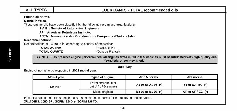
ESSENTIAL : To preserve engine performances, all engines fitted in CITROEN vehicles must be lubricated with high quality oils(synthetic or semi-synthetic)
LUBRICANTS - TOTAL recommended oilsALL TYPES
Engine oil norms.Norms in force.These engine oils have been classified by the following recognised organisations:
S.A.E. : Society of Automotive Engineers.API : American Petroleum Institute.ACEA : Association des Constructeurs Européens d’Automobiles.
Recommendations.Denominations of TOTAL oils, according to country of marketing:
TOTAL ACTIVA (France only).TOTAL QUARTZ (Outside France).
SummaryEngine oil norms to be respected in 2001 model year .
(*) = It is essential not to use engine oils respecting these norms for the following engine-types .XU10J4RS. 1580 SPI. SOFIM 2.8 D et SOFIM 2.8 TD.
Model year
AM 2001Petrol and dual fuelpetrol / LPG engines A3-98 or A1-98 (*) SJ or SJ / EC (*)
CF or CF / EC (*)B3-98 or B1-98 (*)Diesel engines
Types of engine ACEA norms API norms

19
GE
NE
RA
L
LUBRICANTS - TOTAL recommended oils ALL TYPESS.A.E. grades SPI norms ACEA norms
Blended oils for all engines (petrol, dual-fuel petrol / LPG and diesel)
TOTAL ACTIVA 9000
TOTAL QUARTZ 90005W-40 SJ / CF A3-98 / B3-98
TOTAL ACTIVA 9000 (*)
TOTAL QUARTZ 9000 (*) 5W-30 SJ / CF EC A1-98 / B1-98
TOTAL ACTIVRAC 10W-40 SJ / CF A3-98 / B3-98(*) = Blended oils for all engines, permitting fuel economy.
Oils specifically for petrol and dual-fuel petrol / LPG engines
TOTAL ACTIVA 7000
TOTAL QUARTZ 700010W-40
TOTAL QUARTZ 9000 0W-40 SJ A3-98TOTAL ACTIVA 7000
TOTAL QUARTZ 700015W-50
Oils specifically for diesel engines
TOTAL ACTIVA DIESEL 7000TOTAL QUARTZ DIESEL 7000
10W-40
TOTAL ACTIVA DIESEL 7000 15W-50CF B3-98
TOTAL ACTIVA DIESEL 9000 5W-40

20
GE
NE
RA
L
FRANCE
Metropolitan FRANCE
Metropolitan FRANCE
New CaledoniaGuadeloupeSaint-MartinLa Réunion
9000 5W-40 7000 15W-50 7000 15W-50MartiniqueGuyanaTahitiMauritiusMayotte
LUBRICANTS - TOTAL recommended oils
Blended oils for all engines, supplied in bulk
TOTAL ACTIVRAC S.A.E : 10W-40 Norms
TOTAL ACTIVA
Blended oils for all engines
900 5W-40 (*)9000 5W-30 (**) 7000 10 W-40
7000 10 W-409000 5W-40
Oils specifically for petrol anddual-fuel petrol / LPG engines
Oils specificallyfor diesel engines
TOTAL ACTIVA DIESEL
(*) = HDi FAP (Particle filter) - (**) = Blended oils for all engines, permitting fuel economy.
ALL TYPES

21
GE
NE
RA
L
EUROPE
7000 10W-409000 0W-407000 10W-407000 10W-409000 0W-40
7000 10W-407000 15W507000 10W-407000 10W-409000 0W-407000 10W-407000 15W-507000 10W-407000 10W-409000 0W-407000 10W-40
Germany
Austria
Belgium
BulgariaCyprusCroatia
Denmark
Spain
Finland
Great Britain
LUBRICANTS - TOTAL recommended oils ALL TYPES
TOTAL QUARTZ TOTAL QUARTZ DIESEL
Blended oils for all enginesOils specifically for petrol anddual-fuel petrol / LPG engines
Oils specifically for dieselengines
7000 10W-409000 5W-40
9000 5W-30 (*)
(*) = Blended oils for all engines,permitting fuel economy

22
GE
NE
RA
L
EUROPE (continued)
7000 10W-407000 15W-507000 10W-409000 0W-40
7000 10W-40
7000 10W-409000 0W-407000 10W-407000 10W-407000 15W-507000 10W-407000 10W-409000 0W-40
7000 10W-40
Greece
HollandHungaryItalyIrelandIcelandLatviaLithuaniaMacedonia
Malta
Moldova
Norway
PolandPortugalSlovak Republic
LUBRICANTS - TOTAL recommended oilsALL TYPES
TOTAL QUARTZ TOTAL QUARTZ DIESEL
Blended oils for all enginesOils specifically for petrol anddual-fuel petrol / LPG engines
Oils specifically for dieselengines
9000 5W-409000 5W-30 (*)
7000 10W-40
(*) = Blended oils for all engines,permitting fuel economy

23
GE
NE
RA
L
EUROPE (continued)
7000 10W-409000 0W-40
7000 10W-407000 15W-50
7000 10W-409000 0W-40
7000 10W-40
7000 10W-409000 0W-40
7000 10W-40
7000 10W-407000 15W-509000 0W-40
7000 10W-409000 0W-407000 10W-40
Czech Republic
Romania
Russia
Slovenia
Sweden
Switzerland
Turkey
Ukraine
Yugoslavia
LUBRICANTS - TOTAL recommended oils ALL TYPES
TOTAL QUARTZ TOTAL QUARTZ DIESEL
Blended oils for all enginesOils specifically for petrol anddual-fuel petrol / LPG engines
Oils specifically for dieselengines
9000 5W-409000 5W-30 (*)
7000 10W-40
(*) = Blended oils for all engines,permitting fuel economy

24
GE
NE
RA
L
AustraliaNew-Zealand
Ivory CoastEgyptGabonMadagascarMoroccoSenegalTunisia
ArgentinaBrazil, ChileCubaMexicoParaguayUruguay
LUBRICANTS - TOTAL recommended oilsALL TYPES
TOTAL QUARTZ TOTAL QUARTZ DIESEL
Blended oils for allengines
Oils specifically for petrol anddual-fuel petrol / LPG engines
Oils specifically for dieselengines
OCEANIA
AFRICA
9000 5W-40
7000 15W-50
7000 10W-40
7000 10W-40
CENTRALAND SOUTHAMERICA

25
GE
NE
RA
L
LUBRICANTS - TOTAL recommended oils ALL TYPES
China
South Korea
Hong KongIndiaIndonesia
Japan
MalaysiaPakistanPhilippinesSingapore
Taïwan
Thaïland
Vietnam
7000 10W-407000 15W-50
7000 10W-40
7000 15W-50
7000 10W-407000 15W-50
7000 15W-50
7000 10W-407000 15W-50
7000 15W-50
TOTAL QUARTZ TOTAL QUARTZ DIESEL
Blended oils for allengines
Oils specifically for petrol anddual-fuel petrol / LPG engines
Oils specifically for dieselengines
SOUTH EASTASIA
9000 5W-40
9000 5W-409000 5W-30
7000 10W-40
9000 5W-40
(*) = Blended oils for all engines,permitting fuel economy

26
GE
NE
RA
L
MIDDLE9000 5W-40 7000 15W-50 7000 10W-50
EAST
LUBRICANTS - TOTAL recommended oilsALL TYPES
TOTAL QUARTZ TOTAL QUARTZ DIESEL
Blended oils for allengines
Oils specifically for petrol anddual-fuel petrol / LPG engines
Oils specifically for dieselengines
Saudi Arabia
Bahrain
Dubai
United Arab Emirates
Iran
Israel
Jordan
Kuwait
Lebanon
Oman
Qatar
Yemen

27
GE
NE
RA
L
TOTAL TRANSMISSION BVNorms S.A.E 75W-80
Special oil distributed by CITROËN(Part No. 9730 A2)
TOTAL FLUIDE ATX orTOTAL FLUIDE AT 42.
Special oil distributed by CITROËN(Part No. 9730 A3).
Special oil distributed by CITROËN(Part No. 9736 22).
TOATAL TRANSMISSION X 4
TOTAL FLUIDE ATX
TOTAL FLUIDE DASpecial oil distributed by CITROËN
(Part No. 9730 A1)
Manual gearbox
MB3 automatic gearbox
4 HP 20 and AL4 automatic gearboxes
Transfer box and rear axle
Power- assisted steering
LUBRICANTS - TOTAL recommended oils ALL TYPESGearbox oils
Power steering oils
All countries
Very cold countries
All countries

28
GE
NE
RA
L
Engine coolant fluid
LUBRICANTS - TOTAL recommended oilsALL TYPES
PacksCITROEN reference
GLYSANTIN G 33 REVCOGEL 2000
CITROEN Fluid 2 litres 9979 70 9979 72All countries
Protection : - 35°C 5 litres 9979 71 9979 73
20 litres 9979 76 9979 74
210 litres 9979 77 9979 75
Synthetic brake fluid
Pack CITROEN reference
All countries CITROEN Fluid0.5 litre 9979 05
1 litre 9979 06
5litres 9979 07
CITROEN hydraulic circuit fluid
Norm Pack CITROEN reference
All countries TOTAL LHM PLUSISO 7308-7309 ZCP 830 095
Green in colour 1 litre 9979.20 (Scandinavia)
TOTAL FLUIDE LDS Orange in colour 9979.69

29
GE
NE
RA
LPacks CITROEN reference
Concentrated : 250 ml 9980 33 ZC 9875 953 U 9980 56All countries
Liquid ready to use: 1 litre 9980 06 ZC 9875 784 U
Liquid ready to use: 5 litres 9980 05 ZC 9885 077 U ZC 9875 279 U
Grease
Norms NLGI (1)
TOTAL MULTIS EP2 2All countries TOTAL MULTIS COMPLEX EP2 2
TOTAL MULTIS N4128 1
TOTAL SMALL MECHANISMS
(1) NLGI = National Lubricating Grease Institute.
WARNING: TOTAL LDS fluid cannot be blended with TOTAL LHM PLUS.
WARNING: CITROËN C5 : Use only TOTAL FLUIDE LDS suspension fluid.
Hydraulic circuit rinsing fluid- green in colour
TOTAL HYDRAURINCAGE
Wash/wipe fluid
LUBRICANTS - TOTAL recommended oils ALL TYPES
All countries
All countries

30
GE
NE
RA
L
ENGINE OIL CONSUMPTION
I - Oil consumption depends on :- the engine type.- how run-in or worn it is.- the type of oil used.- the driving conditions.
II - An engine can be considered RUN-IN after:
- 3,000 miles (5,000 km) for a PETROL engine.- 6,000 miles (10,000 km) for a DIESEL engine.
III - MAXIMUM PERMISSIBLE oil consumption for a RUN-IN engine.
- 0.5 litres per 600 miles (1,000 km) for a PETROL engine- 1 litre per 600 miles (1,000 km) for a DIESEL engine.DO NOT WORK BELOW THESE VALUES.
IV - OIL LEVEL : The level should NEVER be above the MAX. mark on the dipstick after changing or topping up the oil.- This excess oil will be used up rapidly.- It will reduce the engine output and adversely affect the operation of the air circuits and gas recycling.
ALL TYPES

31
EN
GIN
E
Engine type
Cubic capacity (cc)
Bore / Stroke
Compression ratio
Power ISO or EEC KW - rpm
Power DIN (HP - rpm)
Torque ISO or EEC (m.daN - rpm)
ENGINE SPECIFICATIONS ALL TYPES
Engines : 6FZ - RFN - RLZ - XFX
Petrol
1.8i 16V 2.0i 16V 3.0i-V62.0 HPi
6FZ RFN RLZ XFZ
1749 1997 2946
82.7/81.4 85/88 87/82.6
10.8/1 11.4/1 10.9/1
85-5500 100-6000 103-6000 152-6000
117-5500 136-6000 143-6000 210-6000
16-4000 19-4600 19.2-4100 28.5-3750

32
EN
GIN
E
Engine type
Cubic capacity (cc)
Bore / Stroke
Compression ratio
Power ISO or EEC KW - rpm
Power DIN (HP - rpm)
Torque ISO or EEC (m.daN - rpm)
ENGINE SPECIFICATIONSALL TYPESEngines : RHS - RHZ - RHY - RHW - 4HX
Diesel
2.0 HDi 2.0 HDi 16V 2.2 HDi
RHS RHZ RHY RHW 4HX
1997 2179
85/88 85/96
17.6/1 18/1
79-4000 80-4000 66-4000 80-4000 98-4000
107-4000 110-4000 90-4000 110-4000 13.6-4000
25-1750 20.5-1750 27-1750 31.7-2000

33
EN
GIN
E
RHY
RHS
RHZ
RHW
4HX DW12
DW10
20 ± 5
30 ± 55
COMPRESSION RATIO - DIESEL ENGINES ALL TYPES
ENGINECOMPRESSION
RATIOMAX. SPACING
BETWEEN CYLINDERS
In bars

34
EN
GIN
E
SPECIAL FEATURES : TIGHTENING TORQUES (m.daN)
Crankshaft Petrol Diesel
6FZ RFN RLZ RHY RHS RHZ 4HX
Engines : 6FZ - RFN - RLZ - RHY - RHS - RHZ - 4HX
Bearing cap screws.- Pre-tightening 2 ± 0.1 2.5 ± 0.2- Angular tightening 60° ± 6° 60°
Con-rod cap screws.- Tightening- Slackening- Tightening 2.3 ± 0.2- Angular tightening 46° + 2° - 4°
Con-rod nuts.- Pre-tightening 2 ± 0.2- Angular tightening 70°
Accessories drive pulley- Tightening 2.1 ± 0.1 4 ± 0.4 7 ± 0.25- Angular tightening 51° 60°
Accessories drive pulley hub- Pre-tightening 4 ± 0.4- Angular tightening (Sintered washer) 40° ± 4°- Angular tightening (Steel washer) 53° ± 5°
1180°
2.3 ± 0.146° ± 5

35
EN
GIN
ESPECIAL FEATURES : TIGHTENING TORQUES (m.daN)
Cylinder block Petrol Diesel
6FZ RFN RLZ RHY RHS RHZ 4HX
Engines : 6FZ - RFN - RLZ - RHY - RHS - RHZ - 4HX
Piston skirt spray jet 1 ± 0.1
Sump
- Pre-tightening- Tightening 0.8 ± 0.2 1.6 ± 0.2
Timing belt guide roller
- Pre-tightening- Tightening 3.7 ± 0.3 2.5 ± 0.2
Timing guide roller
- Pre-tightening- Tightening 2.5 ± 0.2
Timing belt tensioner roller 2.1 ± 0.2 2.5 ± 0.2
RH engine mounting- Pre-tightening- Tightening- - Tightening 6.1 ± 0.6 2.7 ± 0.2
11.6 ± 0.3
1.54.3 ± 0.4
1.54.3 ± 0.4
1 (4 screws)2 ± 0.2(Ø 8)
4.5±0.2(Ø10)

36
EN
GIN
E
SPECIAL FEATURES : TIGHTENING TORQUES (m.daN)
Cylinder head Petrol Diesel
6FZ RFN RLZ RHY RHS RHZ 4HX
Engines : 6FZ - RFN - RLZ - RHY - RHS - RHZ - 4HX
Camshaft bearing cover- Tightening- Pre-tightening 0.5 ± 0.1- Tightening 0.9 ± 0.1 1 ± 0.1
Exhaust manifold- Pre-tightening- Tightening 3.5 ± 0.3 2 ± 0.2
Valve cover- Pre-tightening 0.5- Tightening 1.1 ± 0.1 0.9 ± 0.1 0.8 ± 0.1
Camshaft pulley hub 7.5 ± 0.7 4.3 ± 0.5
Hub pulley 2 ± 0.2
Flywheel / Clutch
Flywheel- Pre-tightening 2 ± 0.2- Tightening 21° ± 3° 4.8 ± 0.5
Clutch plate 2 ± 0.2 2 ± 0.2
1 ± 0.10.5 (Ø6)
1±0.1(Ø10)
1.53 ± 0.3
1.54.7 ± 0.4
0.5 ± 0.150.9 ± 0.1

37
EN
GIN
E
Oil pump- Pre-tightening 0.7- Tightening 0.9 ± 0.1 1.3 ± 0.1 0.9 ± 0.1Coolant / oil heat exhanger 5.8 ± 0.5Lubrication pipe- Engine end 3 ± 0.3- Turbocompressor end 2 ± 0.2
Injection circuit
Injector (Flange nut)- Tightening 3 ± 0.3 0.4 ± 0.03- Angular tightening 45° ± 5°Union on injection rail 2 ± 0.2Injection pump 0.5 ± 0.1 2.25 ±0.3 Union on injector 2 ± 0.2Common rail fixing screw 0.9 ± 0.1 0.8 ± 0.1Injection pump pulley 5 ± 0.5Union on injection pump 2.6 ± 0.3 2 ± .02
Cooling circuit Coolant pump 1.4 ± 0.1 1.6 ± 0.3Coolant inlet housing 0.9 ± 0.1 2 ± .02
Engines : 6FZ - RFN - RLZ - RHY - RHZ - 4HX
Lubrication circuit DieselPetrol
6FZ RFN RLZ RHY RHS RHZ 4HX
SPECIAL FEATURES : TIGHTENING TORQUES (m.daN)

38
EN
GIN
E
Nominal dimension Repair dimension
6FZ RFN - RLZ
Marking zone"d"
4 - 5 1-4 2-4-5
Marking zone "e"
R1 R2
Gasket thickness (mm)
0.8 1.1 1.4
Supplier MEILLOR
CYLINDER HEADEngines : 6FZ - RFN - RLZ
Cylinder head gasket identification
C5 - All Types
B1DP183D
Multilayer metallic cylinder head gasket.
(d) Marking zone(e) Marking zone

39
EN
GIN
ECYLINDER HEADEngines : 6FZ - RFN - RLZ
X = MAX. re-usable lengthNOTE: Oil the threads and under the heads of the cylinderhead bolts. (Use engine oil orMolykote G Rapid Plus.)
Pre-tightening 1.5 ± 0.1Tightening 5 ± 0.1Slackening 360°± 2°Tightening 2 ± 0.2Angular tightening 285° ± 5°
(in the order 1 to 10)
B1DP05BC
6FZ - RFN - RLZ
6FZ - RFN - RLZ
X= 147 mm
Cylinder head tightening (m.daN) Cylinder head bolts
A = Washer thickness : 4 ± 0.2 mm .X = Length under heads of the new bolts = 144.5 ± 0.5 mm .
NOTE : Retightening of the cylinder headafter a completed repair isprohibited.Intervention est interdit.
B1DP16FC

40
EN
GIN
E
SPECIAL FEATURES : TIGHTENING TORQUES (m.daN)Engine : XFZ
(1) Compact coil unit 1 ± 0.1
(9) Flywheel- Tightening 1- Angular tightening 60°± 6°
(11) Connecting rod caps- Tightening 2 ±- Angular tightening 74° ± 7
(12) Crankshaft hub- Tightening 4 ± 0.4- Angular tightening 80° ± 8°
(13) Crankshaft pulley 2.5 ± 0.2
B1BP1HAP

41
EN
GIN
ESPECIAL FEATURES : TIGHTENING TORQUES (m.daN)Engine : XFZ
- 2 Cylinder head cover (A) Front cyl. head - (B) Rear cyl. head
WARNING : Tighten screw by screw in the order shown.
- Pre-tighten : 0.5
- Tighten : 1 ± 0.1
- Pre-tighten : 0.2
- Tighten : 0.8
- 3 Bearing caps housing (A) Front cyl. head - (B) Rear cyl. head
B1DP08UD B1DP08TD

42
EN
GIN
E
SPECIAL FEATURES : TIGHTENING TORQUES (m.daN)Engine : XFZ
- 5 Air inlet manifold
WARNING : Tighten screw by screw in the order shown.
- Pre-tighten : 1 ± 0.1
- Tighten : 2 ± 0.2
- Pre-tighten : 1 ± 0.1
- Tighten : 2.5 ± 0.2
- 6 Lower manifold (A) Front cyl. head - (B) Rear cyl. head
B1HPOLJC B1DP097C

43
EN
GIN
ESPECIAL FEATURES : TIGHTENING TORQUES (m.daN)
Engine : XFZ
- 7 Exhaust manifold (NEW seal)
WARNING : Tighten screw by screw in the order shown.
- Pre-tighten : 1 ± 0.1
- Tighten : 3 ± 0.3
- Pre-tighten : 0.5 ±
- Tighten : 0.8 ±
- 10 Oil sump
B1BP1GZDB1BP1GXD

44
EN
GIN
E
SPECIAL FEATURES : TIGHTENING TORQUES (m.daN)
Engine : XFZ
- 8 Crankshaft bearing
B1BP1GYD
- Clean the threads of the screws with a brush.- Refit the screws with a coating of grease
( MOLYKOTE G RAPID PLUS ).- Check that the 8 centring pins are in place.
Maximum length under the heads of the screws :- M11 = 131.5 mm.- M8 = 119 mm.
- Pre-tighten the M11 screws to 3 m.daN ± 0.3 (1 to 8 ).- Pre-tighten the M8 screws to 1 m.daN ± 0.1 (A to H).- Tighten the M6 screws to 1 m.daN± 0.1 (a to m).- Slacken the M11 and M8 screws (screw by screw).- Tighten the M11 screws to 3 m.daN ± 0.3 (1 to 8).- Tighten the M8 screws to 1 m.daN ± 0.1 (A to H).

45
EN
GIN
ESPECIAL FEATURES : TIGHTENING TORQUES (m.daN)
Engine : XFZ
B1BP1HBD
(14) Water pump- Pre-tighten 0.5- Tighten 0.8
(15) Oil pump- Pre-tighten 0.5- Tighten 0.8
(16) Guide roller 8 ± 0.8
(17) Tensioner roller 8 ± 0.8
(18) Camshaft hubs- Pre-tighten 2 ± 0.2- Tighten 57° ± 5°
(19) Camshaft pulley 1 ± 0.1

46
EN
GIN
E
SPECIAL FEATURES : TIGHTENING TORQUES (m.daN)
B1BP1H1D
WARNING : Tighten screw by screw in the order shown.
- Pre-tighten 0.5 ±
- Tighten 1 ± 0.1
Engine : XFZ
- 20 Oil vapour recovery housing.
47
EN
GIN
ECYLINDER HEADEngine : XFZ
Cylinder head gasket identification
B1DP18YD
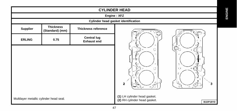
Supplier
ERLING 0.75Central lug
Exhaust end
Thickness(Standard) (mm)
Thickness reference
Multilayer metallic cylinder head seal.(1) LH cylinder head gasket.(2) RH cylinder head gasket.

48
EN
GIN
E
CYLINDER HEADEngine : XFX
X = MAX. re-usable length
Note : Oil the threads and under theheads of the bolts. (Use engine oil orMolykote G Rapid Plus).
In the order indicated.
- Pre-tightening 2 ± 0.2
- Slackening YES
- Pre-tightening 1.5 ± 0.2
- Angular tightening 225°
B1DP09VCB1DP18ZD
XFX
149.5 mm
Cylinder head tightening (m.daN) Cylinder head bolts
49
EN
GIN
ECYLINDER HEAD
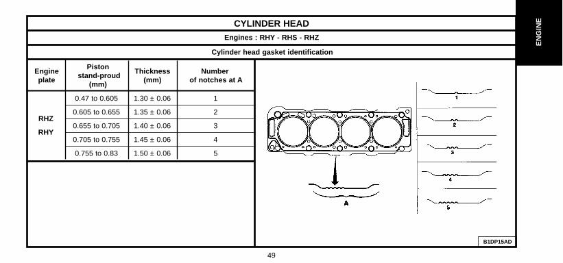
Cylinder head gasket identification
Numberof notches at A
Thickness(mm)
Engineplate
Pistonstand-proud
(mm)
0.47 to 0.605 1.30 ± 0.06 1
0.605 to 0.655 1.35 ± 0.06 2
0.655 to 0.705 1.40 ± 0.06 3
0.705 to 0.755 1.45 ± 0.06 4
0.755 to 0.83 1.50 ± 0.06 5
RHZ
RHY
B1DP15AD
Engines : RHY - RHS - RHZ

50
EN
GIN
E
CYLINDER HEADEngines : RHY - RHS - RHZ
Cylinder head gasket identification
X = MAX. re-usable lengthNOTE : Oil the threads and under the
heads of the bolts. (Use engine oil or
Molykote G Rapid Plus).
- Pre-tightening 2 - Tightening 6 - Angular tightening 220°
B1DP05BC
RHY - RHS - RHZ RHY - RHS - RHZ
RHY - RHS - RHZ
133.3 mm
Cylinder head tightening (m.daN) Cylinder head bolts
B1DP15EC

51
EN
GIN
ECYLINDER HEAD
Cylinder head gasket identification
At BAt A
Number of notches
Thickness(mm)
Engineplate
Pistonstand-proud
(mm)
0.55 to 0.60 1.25 ± 0.04 1
0.61 to 0.65 1.30 ± 0.041
2
0.66 to 0.70 1.35 ± 0.04 3
0.71 to 0.75 1.40 ± 0.04 4
4HX
B1DP18XD
Engine : 4HX
Cylinder head gasket.Multilayer cylinder head gasket.Select seal thickness as a function of the piston stand-proud.

52
EN
GIN
E
CYLINDER HEAD (continued)Engine : 4HX
X = MAX. re-usable length
NOTE : Oil the threads and under theheads of the bolts. (Use engine oil orMolykote G Rapid Plus).
ESSENTIAL : Tighten screw by screw and inthe order indicated.
- Pre-tightening 2 ± 0.2 (Order 1 to 10)- Tightening 6 ± 0.6 (Order 1 to 10)- Slackening 360° (Order 10 to 1)- Pre-tightening 2 ± 0.2 (Order 1 to10)- Tightening 6 ± 0.6 (Order 1 to10)- Angular tightening 220° ± 5° (Order 1 to10)(in 2 attempts max.)
B1DP05BC
4HX 4HX
4HX
X = 134.5 MM
Cylinder head tightening (m.daN) Cylinder head bolts
B1DP15EC

53
EN
GIN
E
Tooling
ALL TYPESBELT TENSION/SEEM UNITS CORRESPONDENCE TABLE
! 4099-T (C.TRONIC.105) 4122-T (C.TRONIC.105.5) !
!!
B1EP135D

54
EN
GIN
E
Engine type 6FZ RFN RLZ XFX RHY RHS RHZ RHW 4HX
C5 X X X X X X X X
SYNERGIE X X X
See pages : 56 57 58 to 61 62 to 63
AUXILIARY EQUIPMENT DRIVE BELT
EW ES
J4 D J4 TD ATED TEDATED4
7 10 9 10 12
C5 - SYNERGIE
DW

55
EN
GIN
EAUXILIARY EQUIPMENT DRIVE BELT ALL TYPES
Engines : All Types Petrol and Diesel
TOOLS
- Belt tension measuring instrument : 4122 - T. (C.TRONIC 105.5)
- WARNING : If using tool 4099-T (C.TRONIC 105) refer to the correspondence table on page 53.
ESSENTIAL
- Before refitting the auxiliary equipment drive belt, check that :
1) The roller(s) rotate freely (no play or stiffness)
2) The belt is correctly engaged in the grooves of the various pulleys.

56
EN
GIN
E
AUXILIARY EQUIPMENT DRIVE BELTSYNERGIEEngines : 6FZ - RFN - RLZWithout aircon With aircon
Tools
[1] Pliers for removing plastic pegs 7504-T
Remove the belt.
- Detension the belt (3) by turning the tensioner roller (1), by the screw (2)(anti-clockwise).
WARNING : the screw (2) has a left hand thread.- Remove the belt (3), while keeping the tensioner roller (1) tensioned.
Refit the belt.
- Compress the tensioner roller (1).- Fit the belt (3).- Release the tensioner roller (1).
Tightening torques m.daN.
Tensioner roller screw (4) 2 ± 0.2Guide roller screw (5) 3.5 ± 0.3
B1BP23PC B1BP23QC B1BP23PC B1BP23RC
57
EN
GIN
EAUXILIARY EQUIPMENT DRIVE BELTEngine : XFX
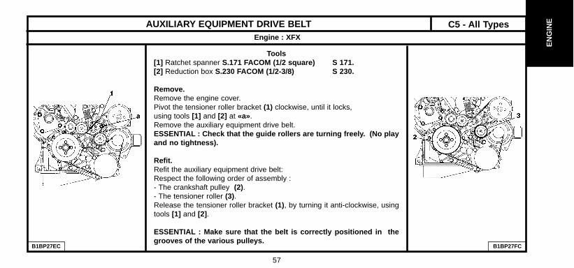
Tools[1] Ratchet spanner S.171 FACOM (1/2 square) S 171.[2] Reduction box S.230 FACOM (1/2-3/8) S 230.
Remove.Remove the engine cover.Pivot the tensioner roller bracket (1) clockwise, until it locks,using tools [1] and [2] at «a».Remove the auxiliary equipment drive belt.ESSENTIAL : Check that the guide rollers are turning freely. (No playand no tightness).
Refit.Refit the auxiliary equipment drive belt: Respect the following order of assembly :- The crankshaft pulley (2).- The tensioner roller (3).Release the tensioner roller bracket (1), by turning it anti-clockwise, usingtools [1] and [2] .
ESSENTIAL : Make sure that the belt is correctly positioned in thegrooves of the various pulleys.
B1BP27EC B1BP27FC
C5 - All Types

58
EN
GIN
E
SYNERGIE AUXILIARY EQUIPMENT DRIVE BELTEngines : RHY - RHS - RHZ
Without air conditioning
B1BP1YKD
Tools
[1] Belt tension adjusting square : (-).0188 J2[2] Ø 4 mm peg : (-).0188.Q1[3] Ø 2 mm peg : (-).0188.Q2[4] Dynamic tensioner compression lever : (-).0188.Z
RemoveRe-use of belt
WARNING : Mark the direction the belt was fitted in case of re-use of the same belt.- Compress the tensioner roller (2) by action at « a » (in anti-clockwise direction), tool [4] .- Keep the tensioner roller (2) compressed and remove the belt.
No re-use of belt.- Compress the dynamic tensioner roller (2) by action at « a » (anti-clockwise), using tool [4] .- Peg using tool [2] , at « b ».- Hold the dynamic tensioner roller (2) compressed and remove the belt.- Loosen the screw (1).

59
EN
GIN
ESYNERGIEAUXILIARY EQUIPMENT DRIVE BELTEngines : RHY - RHZ
Without air conditioning (continued)
Refit.Re-used belt.
- Compress the tensioner roller (2) by action at « a » (anti-clockwise), tool [4] .- Refit the belt.
WARNING : Respect the direction in which the belt is fitted.
- Remove the tool [4].
New belt.
Refit the belt.
- Turn the eccentric roller (3), tool [1] (clockwise) to free the tool [2] from its pegging at « b ».
- Hold the eccentric roller (3), tool [1] , and tighten the screw (1) to 4.3 ± 0.5 m.daN .
Remove the tool [2] .- Rotate the crankshaft 4 times in the direction of rotation.
- Check that it is possible to peg at « b », tool [3] .- If not possible to peg, restart the adjustment.
B1BP1YMD

60
EN
GIN
E
SYNERGIE AUXILIARY EQUIPMENT DRIVE BELTEngines : RHY - RHZ
With air conditioning
B1BP1YLD
Tools[1] Belt tension adjusting square : (-).0188 J2[2] Ø 4 mm peg : (-).0188.Q1[3] Ø 2 mm peg : (-).0188.Q2[4] Dynamic tensioner compression lever : (-).0188.Z
Remove
Re-use of beltWARNING : Mark the direction the belt was fitted in case of re-use of the same belt.- Compress the tensioner roller (7) by moving it at « c » (in anti-clockwise direction), tool [4].- Hold the tensioner roller (7) compressed and remove the belt.
No re-use of belt.- Compress the tensioner roller (7) by moving it at « c » (in anti-clockwise direction), tool [4].- Peg using tool [2] , at « d ».- Loosen the screw (6).- Bring the eccentric roller (5) towards the rear.- Tighten the screw (6) by hand.- Remove the belt.

61
EN
GIN
ESYNERGIEAUXILIARY EQUIPMENT DRIVE BELTEngines : RHY - RHZ
With air conditioning (continued)
Refit.
Re-used belt.- Compress the tensioner roller (7) by action at « c » (in anti-clockwise direction), tool [4] .- Refit the belt.
WARNING : Respect the direction in which the belt is fitted.- Remove the tool [4] .
New belt.Refit the belt.- Turn the eccentric roller (5), tool [1] (clockwise) to free the tool [2] from its pegging at « d ».- Hold the eccentric roller (5), tool [1] , and tighten the screw (6) to 4.3 ± 0.5 m.daN .- Remove the tool [2] .- Rotate the crankshaft 4 times in the normal direction of rotation.- Check that it is possible to peg at « d », tool [3] .- If not possible to peg, restart the adjustment.
B1BP1YND

62
EN
GIN
E
C5 - All Types AUXILIARY EQUIPMENT DRIVE BELTEngine : 4HX
Without air conditioning
B1BP270D B1BP272D
TOOLS
[1] Dynamic tensioner compression lever : (-).0188.Z[2] Peg Ø 4 mm : (-).0188.Q1
Remove.
WARNING : mark the direction of fitting in case the belt is to be reused.
- Compress the tensioner roller (1) by action at «a» (anti-clockwise), using tool [1] .- Peg at «b», using tool [2].- Remove the auxiliaries drive belt.
Refit.- Refit the auxiliaries drive belt.- Compress the tensioner roller (1) by action at «a» (anti-clockwise), using tool [1] .- Remove the tool [2] at «b».

63
EN
GIN
EAUXILIARY EQUIPMENT DRIVE BELTEngine : 4HX
With air conditioning
B1BP271D B1BP273D
TOOLS
[1] Dynamic tensioner compression lever : (-).0188.Z[2] Peg Ø 4 mm : (-).0188.Q1
Remove.
WARNING : mark the direction of fitting in case the belt is to be reused.
- Compress the tensioner roller (4) by action at «c» (anti-clockwise), using tool [1] .- Peg at «d», using tool [2] .- Remove the auxiliaries drive belt.
Refit.- Refit the auxiliaries drive belt.- Compress the tensioner roller (4) by action at «c» (anti-clockwise), using tool [1] .- Remove the tool [2] at «d».
C5 - All Types
64
EN
GIN
E
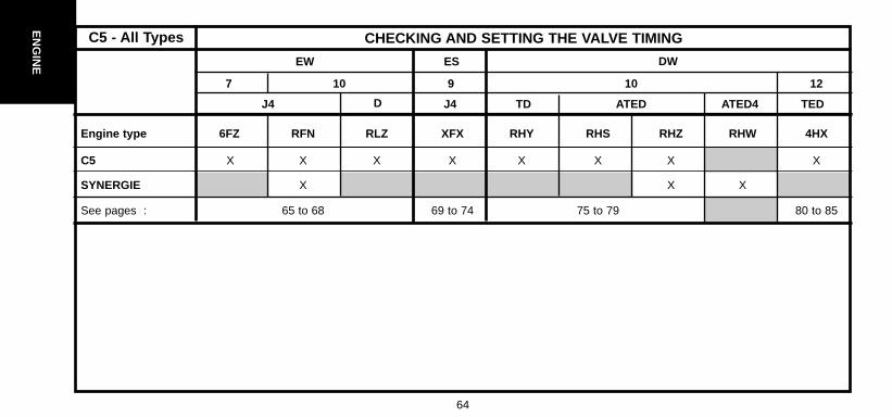
Engine type 6FZ RFN RLZ XFX RHY RHS RHZ RHW 4HX
C5 X X X X X X X X
SYNERGIE X X X
See pages : 65 to 68 69 to 74 75 to 79 80 to 85
CHECKING AND SETTING THE VALVE TIMING
EW ES
J4 D J4 TD ATED TEDATED4
7 10 9 10 12
C5 - All Types
DW

65
EN
GIN
E
TOOLS[1] Camshaft setting pegs : (-).0189.A[2] Crankshaft setting peg : (-).0189.B Toolkit C.0189.[3] Belt retaining pin : (-).0189.K[4] Adaptor for angular tightening : 4069-T[5] Hub immobilising tool : 6310-TChecking the valve timing.- Turn the engine by the crankshaft pinion screw (1) to bring it to pegging position.- Peg the crankshaft, using tool [2] .- Peg the camshaft pulleys, using tools [1] .NOTE : The pegs [1] should engage without effort.WARNING : if the pegs do not engage without effort, restart the fitting andtensioning of the timing belt (see below).Setting the valve timing.Remove.- Remove the screws (2), the pulley (1), upper valve cover (4), lower valve cover (3).- Turn the engine by the screw (13) of the pinion (12) to bring it to pegging position.- Peg the pulleys (8) and (9) using tools [1] .- Peg the pinion (12) using tool [2] .- Loosen the screw (7) of the tensioner roller (6).- Turn the tensioner roller (6) (clockwise).- Remove the timing belt (10).
CHECKING AND SETTING THE VALVE TIMINGEngines : 6FZ - RFN - RLZ
B1EP14JDB1BP23XCB1BP25PCB1BP22SC
C5 - All Types

66
EN
GIN
E
Refit (continued)
- Refit the belt (10) on the pinion (12).- Hold the belt (10) with tool [3] .- Position the belt (10) in the following order :- The guide roller (11), the inlet camshaft pinion (9), the exhaust camshaft pinion (8), the water pump (5), the tensionerroller (6).
NOTE : Make sure that the belt (10) is as flush as possilble with the outer face of the various pinions and rollers.- Remove the tools [3] and [1] .Timing belt.Adjusting the tension.- Turn the roller (6) in the direction of the arrow «b»; using an Allen key at «a».-Position the index «c» in its maximum setting at «d».IMPERATIVE : The index «c» must stand proud of the notch «f» by an angular value of 10°. If it does not,replace the tensioner roller (6) or the timing belt and the tensioner roller (6)Bring the index «c» to its adjusting position «f» by turning the tensioner roller (6) in the direction of the arrow «e»WARNING: The index «c» must not stand proud of the notch «f» : if it does, restart the timing belt tensioningoperation.IMPERATIVE : The tensioner roller (6) must not turn while its fixing is being tightened up. If it does,recomm ence the adjusting operation.
CHECKING AND SETTING THE VALVE TIMINGEngines : 6FZ - RFN - RLZ
B1EP14KCB1EP14JD
C5 - All Types

67
EN
GIN
E
Adjusting the tension (continued).-Tighten the screw (7) of the the tensioner roller (6) to 2.1 ± 0.2 m.daN .
IMPERATIVE : The hexagonal drive of the tensioner roller (6) must be at 15° below the level of the cylinderhead gasket «g». If not, replace the tensioner roller (6) or the timing belt and the tensioner roller (6).
Refit (continued).- Remove the tools [1] and [2] .-Turn the crankshaft 10 times in the normal direction of rotation.
IMPERATIVE : No pressure or outside action must be brought to bear on the timing belt.- Peg the inlet camshaft pulley, using the tool [1].
Checks.Timing belt tension.
IMPERATIVE : Check the position of the index «c», it should be facing the notch «f». If the position of index «c»is not correct, restart the adjustment of its position.
Positioning of the crankshaft.- Fit tool [2] .- As long as it is possible to fit tool [2] , continue with the refit operations.
IMPERATIVE : If it is not possible to fit tool [2], reposition the flange (14).
C5 - All TypesCHECKING AND SETTING THE VALVE TIMINGEngines : 6FZ - RFN - RLZ
B1EP14VCB1EP14MC

68
EN
GIN
E
Checks (continued)
Repositioning the flange.-Immobilise the crankshaft using tool [5] .-Loosen the screw (13).-Release the pinion (12) of the crankshaft.-Bring the flange (14) to the pegging position; using tool [5] .-Fit the tool [2] .-Immobilise the crankshaft using tool [5] .-Tighten screw (13) to 4 ± 0.4 m.daN , then angular tighten to :
53° ± 4° (Assembly with steel washer, gold in colour)40° ± 4° (Assembly with sintered washer, metallic in colour)
using the tool [4] .Remove tools [1]. [2] and [5].
Refit :- The lower valve cover (3).-The upper valve cover (4).-The crankshaft pulley (1).-The screws (2).-Pretighten the screws (2) to 1.5 m.daN .-Tighten the screws (2) to 2.1 ± 0.5 m.daN .
CHECKING AND SETTING THE VALVE TIMINGEngines : 6FZ - RFN - RLZ
B1BP23XCB1EP14PC B1EP14JD
C5 - All Types

69
C5 - All Types
EN
GIN
ECHECKING AND SETTING THE VALVE TIMINGEngine : XFX
OUTILLAGES
[1] Camshaft setting pegs (-).0187.B[2] Crankshaft setting peg (-).0187.A[3] Fuel pressure take-off union 4192-T[4] Belt retaining pin (-).0187.J[5] Exhaust camshaft hubs immobilising tool (-).0187.F[6] Inlet camshaft hubs immobilising tool (-).0187.F
Remove the auxiliaries drive belt (See corresponding operation).
Checking the valve timing setting.
Remove :- The power steering pulley.- The roller / dynamic tensioner assembly (11).- The crankshaft pulley (12).- The upper timing covers (9) and (10).- The lower timing cover (13).
B1BP2BKC

C5 - All Types
70
EN
GIN
E
CHECKING AND SETTING THE VALVE TIMINGEngine : XFX
Checking the valve timing setting (continued).
- Peg the crankshaft, using tool [1] .- Check that the tool [2] engages without effort in the cylinder heads at the camshaft pulleys.- Remove the tools [1] and [2] .
Refit :
- The lower timing cover (13).- The upper timing covers (9) and (10).- The crankshaft pulley (12).- The roller / dynamic tensioner assembly (11).- The power steering pulley.
- Complete the refitting of components.
- Initialise the ignition injection ECU.
B1EP15UDB1EP08TC

71
C5 - All Types
EN
GIN
ECHECKING AND SETTING THE VALVE TIMINGEngine : XFX
Setting the valve timing- Remove the components as necessary for the operation.- Remove the screws (19) and the plate (20).- Peg the crankshaft, using tool [2].
NOTE : Damp the rotation of the camshafts (15) and (17), using tool [6] .- Untighten the camshaft pulley screws (15) and (17).
NOTE : Damp the rotation of the camshafts (14) and (18), using tool [5] .- Untighten the camshaft pulley screws (14) and (18).
NOTE : Lubricate the tools [1] , with grease G6 (TOTAL MULTIS).Peg the camshafts, using tools [1] , [5] and [6] .Remove the screw (21) of the panel (25).Untighten the nut (23) of the tensioner roller (24).Untighten the screws (22) of the panel (25).Remove the guide roller (16).
WARNING : mark the direction of fitting of the timing belt, in case the belt is to be reused
- Remove the timing belt.
B1EP15VD

C5 - All Types
72
EN
GIN
E
CHECKING AND SETTING THE VALVE TIMINGEngine : XFX
Setting the valve timing (continued)Refit.- Check that the camshafts and the crankshaft are correctly pegged.- Check that the rollers and the water pump pulley are turning freely. (No tightness).- Loosen the camshaft pulley screws by a 1/4 turn .- Make sure that the pulleys are turning freely on the camshaft hub.- Turn the camshaft pulleys in a clockwise direction, to end of slots.WARNING : Respect the direction of fitting of the belt : facing the timing, the inscriptionson the belt should be readable the correct way up.- Fit the timing belt on the crankshaft pinion.- Position the tool [6].- Position the timing belt in the following sequence : (Belt well tensioned).- The roller (26), the pulley (18), the pulley (17), - Keep the timing belt well tensioned :- Refit the guide roller (16), tighten to 8 ± 0,8 m.daN .- Position the timing in the following sequence : - The camshaft pulley (15), the camshaft pulley (14), the tensioner roller (24), the water pump pulley,and the guide roller (27).
NOTE : When positioning the belt on the camshaft pulleys, turn these clockwise so as to engage thenext tooth. The angular displacement of the pulleys should not be more than the equivalent ofone tooth.
B1EP15VD B1BP2BLC

73
C5 - All Types
EN
GIN
ECHECKING AND SETTING THE VALVE TIMINGEngine : XFX
Setting the valve timing (continued)
Adjusting the timing belt tension.
- Pivot the plate (25) of the tensioner roller (24), using a spanner.(type FACOM S.161).
- Engage the screw (21) on the plate (25).- Tighten the screws (21) and (22), tighten to 2,5 ± 0,1 m.daN .- Position the belt under maximum tension ; pivot the tensioner roller (24),using a spanner
(type FACOM R 161).- Tighten the nut (23) of the tensioner roller (24), tighten to 1 ± 0,1 m.dan . - Check that the camshaft pinion screws are not at the end of slots.
(By loosening one screw).- Otherwise, restart the operation of positioning the timing belt.- Tighten at least 2 screws per camshaft pulley to 1 ± 0,1 m.daN .- Remove the tools [1] , [2] and [4].- Rotate the crankshaft 2 turns in a clockwise direction.IMPERATIVE : Never turn it back.- Peg the crankshaft, using tool [2] , and the camshaft pulleys, using tool [1] .- Untighten the nut (23) of the tensioner roller (24).- Adjust the belt tension, pivoting the roller (24) using tool (type FACOM S.161).
B1EP15WC B1EP15XC

C5 - All Types
74
CHECKING AND SETTING THE VALVE TIMINGEngine : XFX
Setting the valve timing (continued)- Align the marks «c» and «d», without detensioning the timing belt.(Failing this, restart the operation of adjusting the belt tension).- Hold the tensioner roller (24).- Tighten the nut (23), tighten to 1 ± 0,1 m.daN .- Check the position of the tensioner roller.- Remove the tools [1] , [2] and [4] .- Turn the crankshaft 2 rotations in the direction of engine rotation.IMPERATIVE : Never turn it back.- Peg the crankshaft, using tool [2] .- Check the roller position (24) (the alignment of the marks «c» and «d» should be correct)- Peg the camshaft pinions, using tool [1] .- If the peg [1] goes in, loosen the camshaft pulley screws by 45°.- If the peg [1] does not go in, then loosen the camshaft pulley screws by 45° and manoeuvre thehub using tool [5] until pegging is achieved.WARNING : Check that the camshaft pinion pulleys are not at the end of slots. Otherwise, restart theoperation of positioning the timing belt.- Tighten the camshaft pinion screws to 1 ± 0,1 m.daN .- Remove the tools [1] and [2] .- Refit the panel (20), the screws (19) and tighten to 4 ± 0, m.daN .- Complete the refitting of all components.
B1EP15XC
EN
GIN
E

75
C5 - All Types
EN
GIN
ECHECKING AND SETTING THE VALVE TIMINGEngines : RHY - RHS - RHZ
Tools[1] Belt tension measuring instrument : 4122-T[2] Tension lever : (-).188.J2[3] Engine flywheel peg : (-).188.X[4] Belt retaining pin : (-).0188.K[5] Camshaft pinion peg : (-).0188.M[6] Engine flywheel lock : (-).0188.F[7] Set of blocking plugs : (-).0188.T[8] Crankshaft pulley extractor : (-).0188.P
Checking the setting of the valve timing.Peg : - The engine flywheel, using tool [3] . (From under the vehicle).- The camshaft, using tool [5] .WARNING : On removing screws (6), (7), (9), and (5) of the timing cover, refit thescrew (5) equipped with a spacer (thickness: 17 mm)Tighten to 1,5 ± 0,1 m.daN.(The screw (5) is one of the screws fixing and sealing the water pump).WARNING : Should it be impossible to peg the camshaft, check that the offsetbetween the camshaft pinion hole and the pegging hole is not more than1 mm, with the help of a mirror « a » and a Ø 7 mm screw.
B1BP282C B1BP1YSCB1EP152DB1EP14AC
IMPERATIVE : If pegging is impossible, restart the adjusting.(See corresponding operation).

C5 - All Types
76
Setting the valve timing.
Peg :- The engine flywheel, tool [3]. (From under the vehicle)- The camshaft, tool [5] .
Loosen :- The three screws (9).- The screw (7) of the tensioner roller (6).- Remove the timing belt.
Checks.
IMPERATIVE : Just before refitting, carry out the checks below:
Check that :
- The rollers (20), (23) and the water pump turn freely (without play or tightness).
- There are no traces of oil (on camshaft or crankshaft).
- There are no leaks of coolant fluid (from water pump).
- Replace defective components (if necessary).
CHECKING AND SETTING THE VALVE TIMINGEngines : RHY-RHS-RHZ
B1EP152DB1BP282C
EN
GIN
E

77
C5 - All Types
EN
GIN
ECHECKING AND SETTING THE VALVE TIMINGEngines : RHY - RHS - RHZ
Setting the valve timing (continued).
- Retighten the screws (21) by hand.- Turn the pinion (24) (clockwise) to the bottom of the buttonhole.- Refit the belt on the crankshaft (25).- Hold the belt, using tool [4] .
Reposition the timing belt, keeping the belt tight at «a», in thefollowing order : - Guide roller (23).- Fuel high pressure pump pinion (26).- Camshaft pinion (24).- Water pump pinion (18).- Tensioner roller (20).
NOTE : If needed, slightly turn the pinion (24) anti-clockwise(not by more than one tooth).
- Remove the tool [4].
B1EP154C B1EP155DB1EP153D
C5 - All Types
78
EN
GIN
E
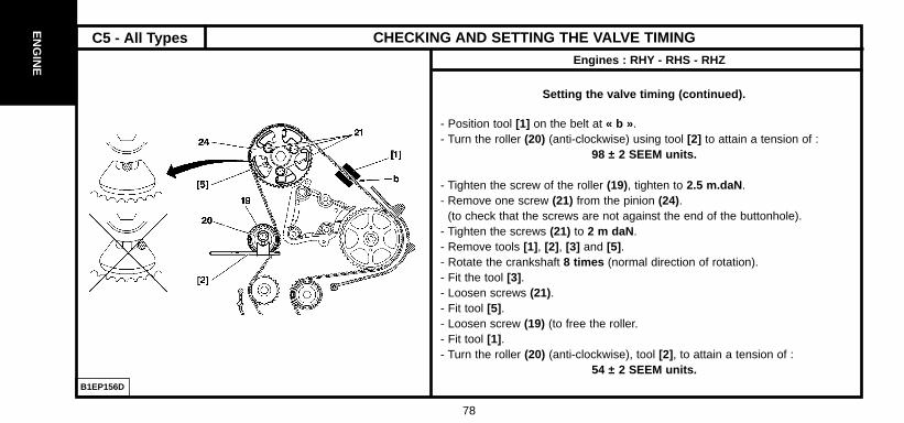
Setting the valve timing (continued).
- Position tool [1] on the belt at « b ».- Turn the roller (20) (anti-clockwise) using tool [2] to attain a tension of :
98 ± 2 SEEM units.
- Tighten the screw of the roller (19), tighten to 2.5 m.daN .- Remove one screw (21) from the pinion (24).
(to check that the screws are not against the end of the buttonhole).- Tighten the screws (21) to 2 m daN .- Remove tools [1] , [2] , [3] and [5] .- Rotate the crankshaft 8 times (normal direction of rotation).- Fit the tool [3] .- Loosen screws (21).- Fit tool [5] .- Loosen screw (19) (to free the roller. - Fit tool [1] .- Turn the roller (20) (anti-clockwise), tool [2] , to attain a tension of :
54 ± 2 SEEM units.
CHECKING AND SETTING THE VALVE TIMINGEngines : RHY - RHS - RHZ
B1EP156D

79
C5 - All Types
EN
GIN
E
Setting the valve timing (continued).Tighten : - The screw of the roller (19) to 2.5 ± 0.2 m.daN .- The screws (21) to 2 ± 0.2 m.daN .- Remove the tool [1] .- Refit the tool [1] .- Tension value should be :
54 ± 3 SEEM units.
IMPERATIVE : If value is incorrect, restart the operation.
- Remove tools [1] , [3] and [5] .- Rotate the crankshaft 2 times (normal direction of rotation).- Fit the tool [3] .
WARNING : Should it be impossible to peg the camshaft, checkthat the offset between the camshaft pinion hole and the pegginghole is not more than 1 mm. In the case of an incorrect value,recommence the operation.
- Remove the tool [3] .- Complete the refitting of components.
CHECKING AND SETTING THE VALVE TIMINGEngines : RHY - RHS - RHZ
B1EP156D

C5 - All Types
80
EN
GIN
E
Tools
[1] Belt tension measuring instrument : 4122-T[2] Engine flywheel peg : (-).0188.X.[3] Tension lever : (-).0188.Y.[4] Belt compression spring : (-).0188.K.[5] Camshaft pinion peg : (-).0188.M.[6] Engine flywheel lock : (-).0188.F.[7] Set of blocking plugs : (-).0188.T.
IMPERATIVE : Respect the safety and cleanliness recommendationsspecific to high pressure diesel injection (HDi) engines.
Checking the setting of the valve timing.
- Turn the crankshaft (normal direction of rotation) and line up the black markingson the chain (b) and (c) with the teeth marked (a) and (d) of the camshaft drivepinions (40 turns max. of the camshaft).
CHECKING AND SETTING THE VALVE TIMINGEngine : 4HX
B1EP159D

81
C5 - All Types
EN
GIN
E
Checking the setting of the valve timing (continued).
IMPERATIVE : If it is impossible to line up the marks on the chain and on the camshaft drivepinions, restart the camshaft setting.(See operation for removing and refitting camshafts).
- If the marks on the chains and pinions are coinciding, continue the checking operations.
Peg : - The crankshaft, using tool [2] .- The camshaft pinion, using tool [5] .
IMPERATIVE : Should it be impossible to peg the camshaft, check that the offset between thecamshaft pinion hole and the pegging hole is not more than 1 mm (use a screw 7 mm in dia.).
If the offset is more than 1 mm, restart the setting of the valve timing (See corresponding operation).- Remove the tools [2] and [5] .
CHECKING AND SETTING THE VALVE TIMINGEngine : 4HX
B1EP15ADB1BP298C
C5 - All Types
82
EN
GIN
E
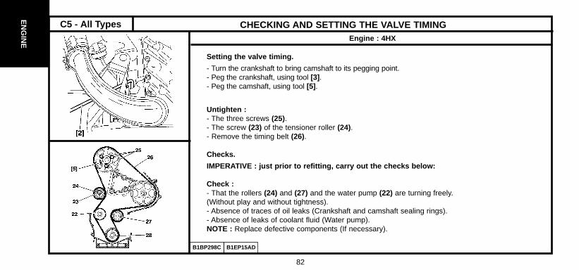
Setting the valve timing.
- Turn the crankshaft to bring camshaft to its pegging point.- Peg the crankshaft, using tool [3] .- Peg the camshaft, using tool [5] .
Untighten : - The three screws (25).- The screw (23) of the tensioner roller (24).- Remove the timing belt (26).
Checks.
IMPERATIVE : just prior to refitting, carry out the checks below:
Check :- That the rollers (24) and (27) and the water pump (22) are turning freely.(Without play and without tightness).- Absence of traces of oil leaks (Crankshaft and camshaft sealing rings).- Absence of leaks of coolant fluid (Water pump).NOTE : Replace defective components (If necessary).
CHECKING AND SETTING THE VALVE TIMINGEngine : 4HX
B1EP15ADB1BP298C

83
C5 - All Types
EN
GIN
ECHECKING AND SETTING THE VALVE TIMINGEngine : 4HX
Setting the valve timing (continued).
Refit- Retighten the screws (25) by hand.- Turn the pinion (29) (clockwise) to the bottom of the buttonhole.- Refit the belt on the crankshaft (28).- Hold the belt, using tool [4] .
Reposition the timing belt, keeping the belt tight at «a», in the following order : - Guide roller (27).- Fuel high pressure pump pinion (30).- Camshaft pinion (29).- Water pump pinion (22).- Tensioner roller (24).
NOTE : If needed, slightly turn the pinion (29) anti-clockwise (not by morethan one tooth).
- Remove the tool [4] .
B1EP15CC B1EP15DDB1EP15BD

C5 - All Types
84
EN
GIN
E
Setting the valve timing (continued)- Position tool [1] on the belt at « b ».- Turn the tensioner roller (24) (anti-clockwise) using tool [2] to attain a tension of :
106 ± 2 SEEM units.- Tighten screw (23) of the tensioner roller, tighten to 2.5 m.daN .- Remove one screw (25) from the pinion (29).
(to check that the screws are not against the end of the buttonhole).- Tighten the screws (25) to 2 m daN .- Remove tools [1] , [2] , [3] and [5] .- Rotate the crankshaft 8 times (normal direction of rotation).- Fit the tool [3] .- Loosen screws (25).- Fit tool [5] .- Loosen screw (23) (to free the tensioner roller (24).- Fit tool [1] .- Turn the tensioner roller (24) (anti-clockwise),using tool [3], to attain a tension of :
51 ± 3 SEEM units.- Tighten :- The screw (23) of the tensioner roller (24) to 2,5 ± 0,2 m.daN .- The screws (25) to 2 ± 0.2 m.daN .
CHECKING AND SETTING THE VALVE TIMINGEngine : 4HX
B1EP15ED

85
C5 - All Types
EN
GIN
E
Setting the valve timing (continued)
- Remove the tool [1] .- Refit the tool [1] .- Tension value should be :
51 ± 3 SEEM units.
IMPERATIVE : If value is incorrect, restart the operation.
- Remove tools [1] , [2] and [5] .- Rotate the crankshaft 2 times (normal direction of rotation).- Fit the tool [3] .
IMPERATIVE : Should it be impossible to peg the camshaft, check that theoffset between the camshaft pinion hole and the pegging hole is not morethan 1 mm. In the case of an incorrect value, recommence the operation.
- Remove the tool [2] .- Complete the refitting of components.
CHECKING AND SETTING THE VALVE TIMINGEngine : 4HX
B1EP15ED

86
EN
GIN
E
ALL TYPES VALVE CLEARANCES
The valve clearances must be checked with the engine cold
Inlet
All Types Hydraulic adjustment
Exhaust
Rocking Adjust
1 1
3 3
4 4
2 2
4 4
2 2
1 1
3 3
Inlet
Exhaust
RockingValves
fully open
Adjust
1
3
4
2
3 4
4 2
2 1
1 3
Fully open (Exhaust)
POSSIBLE PROCEDURESFor engines with 4 cylinders in a line (1-3-4-2 )
Engines without hydraulicadjustment : the clearance (J)should be checked oppositethe cam.
B1DP13QC

87
EN
GIN
ECHECKING THE OIL PRESSURE
Engine type
Temperature (°C)
Pressure (Bars)
Rpm
Engine type
Temperature (C°)
Pressure (Bars)
Rpm
6FZ RFN RLZ XFX
90°C
1.5 5 1.5 5 1.5 5 7 8
1000 3000 1000 3000 1000 3000 900 3000
Diesel engines
1.8i 16V
2.0 HDi 2.2 HDi
2.0i 16V 2.0 HPi 3.0i V6
Petrol enginesToolsToolkit 4103 -T
RHY - RHS -RHZ 4HX
90°
2 4 2 4 2 4
1000 2000 1000 2000 1000 2000
ESSENTIAL : Respect the safety and cleanliness recommendations.
C5 - All Types

C5 - All Types
88
EN
GIN
E To be read together with the petrol and diesel correspondence tables
OIL FILTERS
PURFLUXLS 304
LS 880
Specifications
Ø (mm) Height (mm)
LS 880
LS 304 76 89
86 97
6FZ RFN RLZ XFX RHY RHS RHZ 4HX
X X X X X X X
X

89
C5 - All Types
EN
GIN
EFILLING AND BLEEDING THE COOLING CIRCUIT
TOOLS
[1] Filling cylinder : 4520-T[2] Adaptor for filling cylinder : 4222-T.
ESSENTIAL : Respect the safety and cleanliness recommendations.
- The draining and refilling operations can be carried out by means of a WINN’S coolant replacement appa-ratus or similar; it is essential to follow the instructions when using this apparatus.
Filling and bleeding
- Fit the cylinder adaptor [2] 4222-T and the filling cylinder [1] 4520 -T .- Use the coolant to ensure protection between - 15°C and - 37°C.- Slowly fill the system.
NOTE : Keep the cylinder filled up (visible level).- Close each bleed screw as soon as the coolant flows without air bubbles.- Start the engine : Engine speed 1500 rpm .- Maintain this speed until the third cooling cycle (cooling fans have cut in and cut out).- Stop the engine and allow it to cool down.- Remove the filling cylinder [1] 4520-T and the adaptor [2] 4222-T .- Top up the system to the maximum mark, with the engine cold.- Refit the filler cap.
E5AP1GNCB1GP00AC

C5 - All Types
90
INJE
CT
ION
1.8 i 16V 6FZ
L4
SAGEM S2000 7000IF/L5
C5 2.0 i 16V RFN IF/L5MAGNETTI MARELLI
900 < 0.5 > 9 48P
2.0 HPi RLZ L4SIEMENS
900SIRIUS 81
3.0 i V6 XFZ IF/L5BOSCH
650 600ME 7.4.6.
SYNERGIE 2.0 i 16V RFN IF L5 M. MARELLI 48P2 800 < 0.5 > 9
IDLING - ANTIPOLLUTION
Vehicles Engine typeEmissionstandard Make - Injection type
Idling speed (± 50 rpm)
Manualgearbox
Auto. gearbox: N engaged
% Content
CO CO2
91
C5 - All Types
INJE
CT
ION
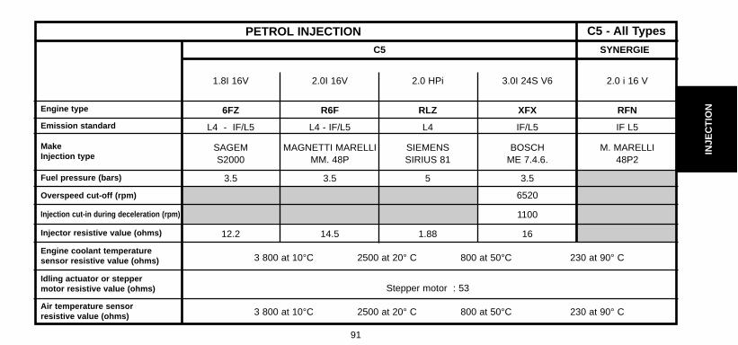
Emission standard
Engine type
Make Injection type
PETROL INJECTION
Air temperature sensorresistive value (ohms)
SYNERGIEC5
Fuel pressure (bars)
Overspeed cut-off (rpm)
Injection cut-in during deceleration (rpm)
Injector resistive value (ohms)
Engine coolant temperature sensor resistive value (ohms)
Idling actuator or steppermotor resistive value (ohms)
1.8I 16V 2.0I 16V 2.0 HPi 3.0I 24S V6 2.0 i 16 V
6FZ R6F RLZ XFX RFN
L4 - IF/L5 L4 - IF/L5 L4 IF/L5 IF L5
SAGEM MAGNETTI MARELLI SIEMENS BOSCH M. MARELLIS2000 MM. 48P SIRIUS 81 ME 7.4.6. 48P2
3.5 3.5 5 3.5
6520
1100
12.2 14.5 1.88 16
3 800 at 10°C 2500 at 20° C 800 at 50°C 230 at 90° C
Stepper motor : 53
3 800 at 10°C 2500 at 20° C 800 at 50°C 230 at 90° C

92
INJE
CT
ION
ANTI-POLLUTION TECHNICAL CHECKS (FRANCE)All Types Petrol CO Corrected (In %) All Types Diesel (m -1)
Conditions : At idle, engine warm.
# 01/96Less than 4.5 % for vehicles registered before 10/86.
Less than 3.5 % for vehicles registered after 10/86.
With catalytic converter Greater than 2.0i 89 M.Y.
All Types 93 M.Y.
CO less than 0.5 % at idle speed.CO less than 0.3 % at fast idle speed between 2500 and 3000 rpm (*)
Lambda Probe value 0.97 to 1.03.
01/96 #
Atmospheric engine.
Less than 2.5 m -1
Turbocharged engine.
Less than 3.0 m -1
ALL TYPES

93
INJE
CT
ION
STANDARD
Brussels directive Private vehicles : 83/351 > 2 litres 06/89 except special • new cyl. < 2 litres 06/92 derogations for certain • existing cyl. < 2 litres 12/92 private vehicles
cyl. > 2 litres K 15.04 PetrolK’ 15.04 Diesel Utility vehicle limits With oxygen sensor,
= private vehicle without catalytic converter
Utility vehicles : 10/89limits increased
All Types imminent by 25 % For private vehicles and utility vehicles in major export
W vp 15.05 Petrol
Private vehicles : Brussels directive 88/76> 2 litres 01/10/88 " Luxembourg Accords " • new models 01/10/89 Replaced by 89/458 • existing models + 91/441
ALL TYPESEMISSION STANDARDS
PSA
A-S RPEngines ApplicableVehicles
ECE R 15.04
ECE R 15.05
E.E.C.
APPLICATIONS NOTES CHARACTERISTICS

94
INJE
CT
ION
STANDARD
Brussels directives 88/76
and 88/436
Utility vehicle limits
private vehicle limits of
W vu 15.05Petrol Brussels directive 88/436 Diesel 7 classes of limits by
vehicle weight
Private vehicles : With oxygen sensor
Z US 83Petrol • certain non-EEC
and catalytic converter Diesel European countries
Current Adoption of the U.S.
for petrol vehicles• certain Export countries
ALL TYPES EMISSION STANDARDS
PSA
A-S RPEngines ApplicableVehicles
ECE R 15.05
US 83
E.E.C.
APPLICATIONS NOTES CHARACTERISTICS
01/10/88
01/10/89
10/94
Utility vehicles :
All Types
• new models
• existing models
95
INJE
CT
ION
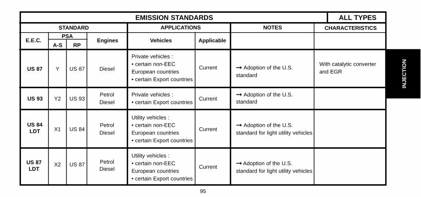
STANDARD
Private vehicles :
Y US 87 Diesel• certain non-EEC With catalytic converterEuropean countries
Current Adoption of the U.S. and EGR
• certain Export countries standard
Y2 US 93Petrol Private vehicles :
Current Adoption of the U.S.
Diesel • certain Export countries standard
Utility vehicles :
X1 US 84 Petrol • certain non-EEC
Current Adoption of the U.S.
Diesel European countries standard for light utility vehicles• certain Export countries
X2 US 87 Petrol Utility vehicles : • certain non-EEC Adoption of the U.S.
Diesel European countriesCurrent
standard for light utility vehicles• certain Export countries
ALL TYPESEMISSION STANDARDS
PSA
A-S RPEngines ApplicableVehicles
US 87
US 93
US 84LDT
US 87 LDT
E.E.C.
APPLICATIONS NOTES CHARACTERISTICS

96
INJE
CT
ION
STANDARD
X3 US 90Petrol
Private vehicles :
Diesel
• certain non-EEC Adoption of the U.S.
European countriesCurrent
standard for light utility vehicles
• certain Export countries
L1CEE Petrol
Private vehicles : Brussels directive
19.5 Diesel
< 1.4 litres 07/92 89/458
• new models 01/07/93
• existing models 31/12/94 Possible alternative to emission
standard L from 1992 to 1994
Private vehicles : With oxygen sensor
CEE PetrolAll Types 07/92 and catalytic converter
L • new models 01/93 EU Brussels Directive 93/59 for petrol vehicles. 19.5 Diesel
• existing models 01/96 (91/441) With catalytic converter
• new models 01/97 and EGR for diesel
• existing models vehicles.
ALL TYPES EMISSION STANDARDS
PSA
A-S RPEngines ApplicableVehicles
US 90LDT
EURO 1
( EURO93)
EURO 1
( EURO93)
E.E.C.
APPLICATIONS NOTES CHARACTERISTICS

97
INJE
CT
ION
STANDARD
Utility vehicles :
< 3.5 tonnes
• new models 01/10/93
• existing models 01/10/94
W2CEE Petrol
Class 1 :W2 Diesel
• new models 01/97
• existing models 10/97
Class 2/3 :
• new models 01/98
• existing models 10/98
L3CEE Petrol
Private vehicles :
95 Diesel
< 6 seats and 01/96
< 2.5 tonnes01/97
• new models
• existing models
ALL TYPESEMISSION STANDARDS
PSA
A-S RPEngines ApplicableVehicles
EURO 1
(EURO93)
EURO2
(EURO96)
E.E.C.
APPLICATIONS NOTES CHARACTERISTICS
Brussels directive 94/12
EURO 93 standard madestricter
Brussels directive 93/59
3 classes depending on
vehicle weight :
Class 1 < 1250 kg
Class 2 : 1250/1700 kg
Class 3 > 1700 kg
With oxygen sensorand catalytic converterfor petrol vehicles
With oxygen sensor andreinforced catalyticconverter for petrolvehicles. With catalyticconverter and EGR fordiesel vehicles.

98
INJE
CT
ION
STANDARD
Utility vehicles : Brussels directive 96/69< 3.5 tonnesClass 1 : 3 classes depending on
W3CEE
Petrol• new models 01/97 vehicle weight :
95Diesel
• existing models 10/97 Class 1 < 1250 kgGas
Class 2/3 : Class 2 : 1250/1700 kg• new models 01/98 Class 2 : 1 700 kg• existing models 10/98
L4 CEE Petrol 01/2000
2000Diesel 01/2001
Gas
ALL TYPES EMISSION STANDARDS
PSA
A-S RPEngines ApplicableVehicles
EURO 2
(EURO96)
EURO 3
(EURO2000)
E.E.C.
APPLICATIONS NOTES CHARACTERISTICS
Brussels directive 98/69 EURO 2 standard (L3) made stricter Fiscal incentives
Private vehicles :All Types• nouveaux modèles • modèles existants
With oxygen sensor andreinforced catalyticconverter for petrolvehicles. With catalyticconverter and EGR fordiesel vehicles.
With 2 oxygen sensorsand catalytic converter forpetrol vehicles. With catalytic converterand EGR for dieselvehicles.With EOBDon-board diagnosis.
99
INJE
CT
ION
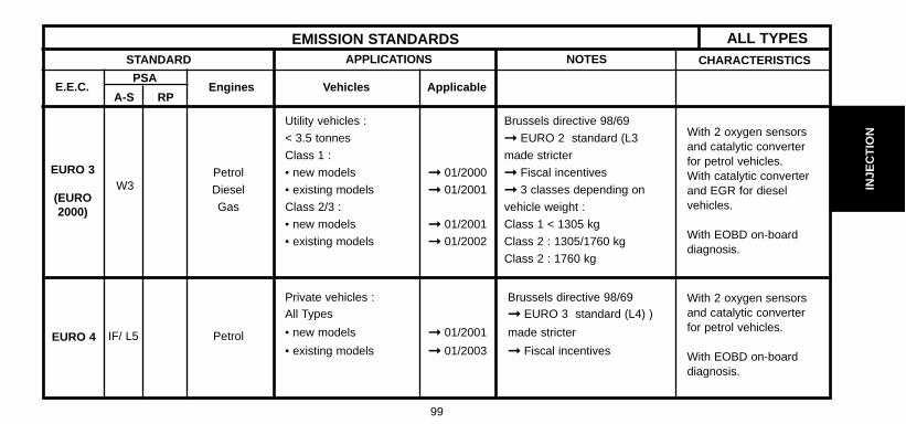
STANDARD
Utility vehicles : Brussels directive 98/69
< 3.5 tonnes EURO 2 standard (L3
Class 1 : made stricter
W3Petrol • new models 01/2000 Fiscal incentives
Diesel • existing models 01/2001 3 classes depending on
Gas Class 2/3 : vehicle weight :
• new models 01/2001 Class 1 < 1305 kg
• existing models 01/2002 Class 2 : 1305/1760 kg
Class 2 : 1760 kg
Private vehicles : Brussels directive 98/69 All Types EURO 3 standard (L4) )
• new models 01/2001 made stricterIF/ L5 Petrol • existing models 01/2003 Fiscal incentives
ALL TYPESEMISSION STANDARDS
PSA
A-S RPEngines ApplicableVehicles
EURO 3
(EURO2000)
EURO 4
E.E.C.
APPLICATIONS NOTES CHARACTERISTICS
With 2 oxygen sensorsand catalytic converterfor petrol vehicles. With catalytic converterand EGR for dieselvehicles.
With EOBD on-boarddiagnosis.
With 2 oxygen sensorsand catalytic converterfor petrol vehicles.
With EOBD on-boarddiagnosis.

100
INJE
CT
ION
STANDARD
ALL TYPES EMISSION STANDARDS
PSA
A-S RPEngines ApplicableVehicles
EURO 4
EURO 4
E.E.C.
APPLICATIONS NOTES CHARACTERISTICS
IF / L5
IF / L5
PetrolDiesel Gas
PetrolGas
Brussels Directive: 2001/1 EURO 3 standard (L4) madestricter Fiscal incentives
Brussels Directives: 99/102 et
2001/1 (Gas) EURO 3 standard (L4) madestricter Fiscal incentives 3 classes depending onvehicle weight :
Class 1 < 1305 kg
Class 2 : 1305/1760 kg
Class 3 : 1760 kg
With 2 oxygen sensors andcatalytic converter for petrolvehicles. With EOBD on-boarddiagnosis.
Private vehicles :
All types
• new models
• existing models
Utility vehicles :
< 3.5 tonnes Class 1 : • new models • existing models Class 2/3 : • new models
• existing models
01/2005
01/2006
01/2005
01/2006
01/2006
01/2007
With 2 oxygen sensorsand catalytic converter forpetrol vehicles.
With EOBD on-boarddiagnosis.

101
INJE
CT
ION
PROHIBITED OPERATIONS: HDi DIRECT INJECTION SYSTEMEngines : RHY - RHS - RHZ - 4HX
Cleaning.- The use of high pressure cleaners is prohibited.- Do not use compressed air.
Fuel supply circuit.- Required fuel : diesel.
Electric circuit.- Swapping injection ECUs between two vehicles will render it impossible to start either vehicle.- It is forbidden to supply a diesel injector with 12 volts.
High pressure fuel pump.Do not separate the following components from the high pressure fuel pump (5) :- Sealing ring (b) (no replacement parts).- High pressure outlet connector (a) (will cause a malfunction).
HDi = High pressure Diesel injection
B1HP19LC
C5 - All Types

102
INJE
CT
ION
PROHIBITED OPERATIONS: HDi DIRECT INJECTION SYSTEMEngines : RHY - RHS - RHZ - 4HX
Diesel injectors.
WARNING: Diesel and ultrasonic cleaners are prohibited.
Do not separate the following components from the diesel injector carrier (2) :- Diesel injector (e) (no replacement parts).- Electromagnetic element (c) (no replacement parts).
Do not alter the position of the nut (d) (malfunction).
Do not separate the connector (f) from a diesel injector.
It is forbidden to clean the carbon deposits from the diesel injector nozzle.
B1HP19NC
C5 - All Types

103
INJE
CT
ION
SAFETY REQUIREMENTS : HDi DIRECT INJECTION SYSTEMEngines : RHY - RHS - RHZ -4 HX
SAFETY REQUIREMENTSPreamble.All interventions on the injection system must be carried out to conform with the following requirements and regulations :- Competent health authorities.- Accident prevention.- Environmental protection.WARNING : Repairs must be carried out by specialised personnel informed of the safety requirements and of the precautions to be taken.
Safety requirements.IMPERATIVE : Take into account the very high pressures in the high pressure fuel circuit (1350 bars), and respectthe requirements below :
- No smoking in proximity to the high pressure circuit when work is being carried out.- Avoid working close to flame or sparks.Engine running : - Do not work on the high pressure fuel circuit.- Always stay clear of the trajectory of any possible jet of fuel, which could cause serious injuries.- Do not place your hand close to any leak in the high pressure fuel circuit.After the engine has stopped, wait 30 seconds before any intervention.NOTE : This waiting time is necessary in order to allow the high pressure fuel circuit to return to atmospheric pressure.
C5 - All Types

104
INJE
CT
ION
SAFETY REQUIREMENTS : HDi DIRECT INJECTION SYSTEMEngines: RHY - RHS - RHZ - 4HX
CLEANLINESS REQUIREMENTS.Preliminary operations
IMPERATIVE : The technician should wear clean overalls.Before working on the injection system, it may be necessary to clean the apertures of the following sensitive components :(refer to corresponding procedures).- Fuel filter.- High pressure fuel pump.- Third piston deactivator.- High pressure regulator.- High pressure sensor.- High pressure fuel injection common rail.- High pressure fuel pipes - Diesel injector carriers.
IMPERATIVE : After dismantling, immediately block the apertures of the sensitive components with plugs, to avoid the entry of i mpurities.Work area.- The work area must be clean and free of clutter.- Components being worked on must be protected from dust contamination.
C5 - All Types
105
INJE
CT
ION
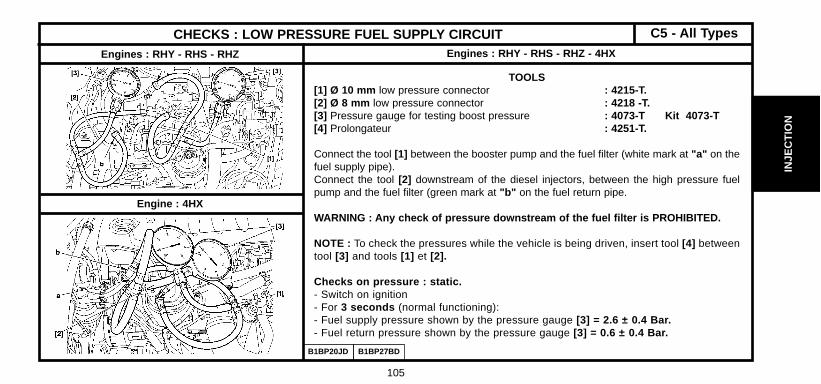
CHECKS : LOW PRESSURE FUEL SUPPLY CIRCUITEngines : RHY - RHS - RHZ - 4HXEngines : RHY - RHS - RHZ
Engine : 4HX
TOOLS[1] Ø 10 mm low pressure connector : 4215-T.[2] Ø 8 mm low pressure connector : 4218 -T.[3] Pressure gauge for testing boost pressure : 4073-T Kit 4073-T[4] Prolongateur : 4251-T.
Connect the tool [1] between the booster pump and the fuel filter (white mark at "a" on thefuel supply pipe).Connect the tool [2] downstream of the diesel injectors, between the high pressure fuelpump and the fuel filter (green mark at "b" on the fuel return pipe.
WARNING : Any check of pressure downstream of the fuel filter is PROHIBITED.
NOTE : To check the pressures while the vehicle is being driven, insert tool [4] betweentool [3] and tools [1] et [2].
Checks on pressure : static.- Switch on ignition- For 3 seconds (normal functioning):- Fuel supply pressure shown by the pressure gauge [3] = 2.6 ± 0.4 Bar.- Fuel return pressure shown by the pressure gauge [3] = 0.6 ± 0.4 Bar.
B1BP20JD B1BP27BD
C5 - All Types

106
INJE
CT
ION
CHECKS : LOW PRESSURE FUEL SUPPLY CIRCUITEngines : RHY - RHS - RHZ - 4HX (continued)
Checks on pressure : dynamic.Engine running, at idle (normal functioning):- Fuel supply pressure shown by the pressure gauge [3] = 2 ± 0.4 Bar.- Fuel return pressure shown by the pressure gauge [3] = 0.8 ± 0.4 Bar.Abnormal functioning
Impossible to start the engine :Fuel supply pressure less than 0.8 Bar :- Check the low pressure regulator incorporated in the filter (locked open)- Check the high pressure pump distribution valve (locked shut)
Check : diesel injector return flow. (Table below)
Uncouple the diesel injector return pipe.
Fuel supply pressure Fuel return pressure Checks
Between 3.3 and 4 Bar 0.8 ± 0.4 Bar Check the condition of the diesel filter
More than 4 Bar
More than 4 Bar
Less than 0.8 Bar
More than 0.8 Bar
Check the low pressure regulator incorporated inthe filter (locked shut) : replace.
Check the fuel return circuit (pipe pinched or trapped.......).
Between 0.8 and 1.5 Bar Less than 0.8 Bar Check the fuel suppy circuit :- Booster pump (low pressure), piping.
Check : Observe :
The flow should be drop by drop Diesel injector functioning correctly
Excessive fuel return Diesel injector locked shut.
C5 - All Types

107
INJE
CT
ION
AIR SUPPLY CIRCUIT SPECIFICATIONEngine : RHY
(1) Air filter PSA 7899
(2) Flowmeter SIEMENS
(3) Water / recycled gas exchanger VALEO
(4) EGR valve PURFLUX
(5) Turbocharger KKK K03
(6) Air butterfly MAGNETI MARELLI48W7 Ref. 648
B1HP1A6D
C5 - All Types
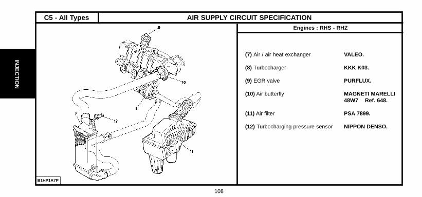
108
INJE
CT
ION
(7) Air / air heat exchanger VALEO.
(8) Turbocharger KKK K03.
(9) EGR valve PURFLUX.
(10) Air butterfly MAGNETI MARELLI48W7 Ref. 648.
(11) Air filter PSA 7899.
(12) Turbocharging pressure sensor NIPPON DENSO.
AIR SUPPLY CIRCUIT SPECIFICATIONEngines : RHS - RHZ
B1HP1A7P
C5 - All Types

109
INJE
CT
ION
AIR SUPPLY CIRCUIT SPECIFICATIONEngine : 4HX
(1) Air / air exchanger
(2) Air / water exchanger
(3) Warm air metering device BOSCH.
(4) Cold air metering device BOSCH.
(5) Turbocharger ALLIEDSIGNAL GT1549P.
(6) Flowmeter SIEMENS.
(7) Air filter PSA 7885.
B1HP1BYP
C5 - All Types

110
INJE
CT
ION
CHECKS : AIR SUPPLY CIRCUITEngine : 4HX
ESSENTIAL : Respect the safety and cleanlinessrecommendations.
Tool.
[1] Manual vacuum pump: FACOMM DA 16.
Checks.
ESSENTIAL : Respect the safety and cleanlinessrecommendations that are specific to high pressurediesel injection (HDi) engines.
B1HP1ARP
C5 - All Types
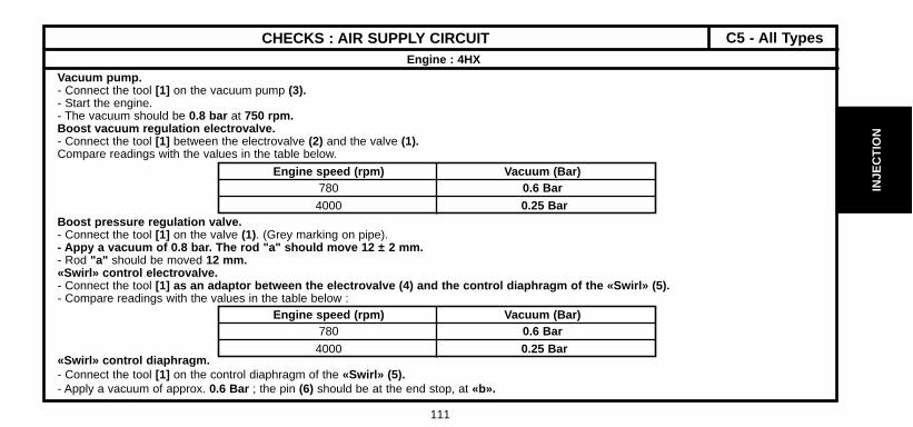
111
INJE
CT
ION
CHECKS : AIR SUPPLY CIRCUITEngine : 4HX
Vacuum pump.- Connect the tool [1] on the vacuum pump (3).- Start the engine.- The vacuum should be 0.8 bar at 750 rpm.Boost vacuum regulation electrovalve.- Connect the tool [1] between the electrovalve (2) and the valve (1).Compare readings with the values in the table below.
Boost pressure regulation valve.- Connect the tool [1] on the valve (1). (Grey marking on pipe).- Appy a vacuum of 0.8 bar. The rod "a" should move 12 ± 2 mm. - Rod "a" should be moved 12 mm.«Swirl» control electrovalve.- Connect the tool [1] as an adaptor between the electrovalve (4) and the control diaphragm of the «Swirl» (5).- Compare readings with the values in the table below :
«Swirl» control diaphragm.- Connect the tool [1] on the control diaphragm of the «Swirl» (5).- Apply a vacuum of approx. 0.6 Bar ; the pin (6) should be at the end stop, at «b».
Engine speed (rpm) Vacuum (Bar)780 0.6 Bar
4000 0.25 Bar
Engine speed (rpm) Vacuum (Bar)780 0.6 Bar
4000 0.25 Bar
C5 - All Types

112
INJE
CT
ION
CHECKS : EXHAUST GAS RECYCLING CIRCUITEngines : RHY - RHS - RHZ
(1) Butterfly housing (3) Electrovalve (black connector)(2) EGR valve (tube with blue marking) (4) Electrovalve (blue connector)
Tools[1] Manual vacuum pump : FACOM DA 16.
ESSENTIAL : Respect the safety and cleanliness requirements specific to highpressure diesel injection (HDi) engines.
EGR electrovalve- Check, not under load, between the electrovalve (4) and the EGR valve (2).- Connect the tool [1] between the electrovalve (3) and the butterfly housing (1).- Compare readings with the values in the table below.
Butterfly housing electrovalve.- Check, not under load, between the electrovalve (3) and the butterfly housing (1).- Connect the tool [1] between the electrovalve (3) and the butterfly housing (1).- Compare readings with the values in the table below.
Engine speed (rpm) Vacuum value (bar)
780 0.5 Bar
2500 0 BarB1HP1BVD
C5 - All Types

113
INJE
CT
ION
CHECKS : EXHAUST GAS RECYCLING CIRCUITEngines : RHY - RHS - RHZ
EGR valve
- Connect tool [1] on the EGR valve capsule take-off (2).- Apply a vacuum of approx. 0.6 bar to activate the EGR valve.- In abruptly suppressing the vacuum, the valve should click and lock itself back on its seating.- Repeat the operation several times.
Butterfly housing
- Remove the air duct between the air/air exchanger and the butterfly housing (5), (1).- Connect tool [1] on the butterfly housing vacuum capsule (1).- Apply a vacuum of approx. 0.8 bar , the flap (a) of the butterfly housing (1) should be closed.
B1HP1BWC B1BP2ADC
C5 - All Types
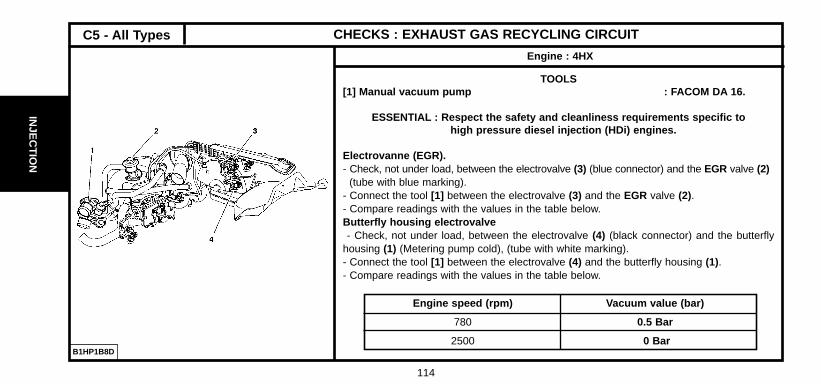
114
INJE
CT
ION
CHECKS : EXHAUST GAS RECYCLING CIRCUIT
Engine : 4HX
TOOLS[1] Manual vacuum pump : FACOM DA 16.
ESSENTIAL : Respect the safety and cleanliness requirements specific to high pressure diesel injection (HDi) engines.
Electrovanne (EGR).- Check, not under load, between the electrovalve (3) (blue connector) and the EGR valve (2)
(tube with blue marking).- Connect the tool [1] between the electrovalve (3) and the EGR valve (2).- Compare readings with the values in the table below.Butterfly housing electrovalve- Check, not under load, between the electrovalve (4) (black connector) and the butterfly
housing (1) (Metering pump cold), (tube with white marking).- Connect the tool [1] between the electrovalve (4) and the butterfly housing (1).- Compare readings with the values in the table below.
Engine speed (rpm) Vacuum value (bar)
780 0.5 Bar
2500 0 BarB1HP1B8D
C5 - All Types
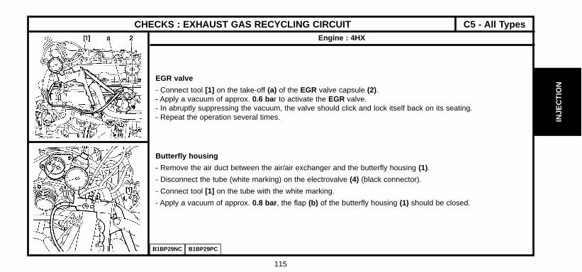
115
INJE
CT
ION
CHECKS : EXHAUST GAS RECYCLING CIRCUITEngine : 4HX
EGR valve
- Connect tool [1] on the take-off (a) of the EGR valve capsule (2).- Apply a vacuum of approx. 0.6 bar to activate the EGR valve.- In abruptly suppressing the vacuum, the valve should click and lock itself back on its seating.- Repeat the operation several times.
Butterfly housing
- Remove the air duct between the air/air exchanger and the butterfly housing (1).
- Disconnect the tube (white marking) on the electrovalve (4) (black connector).
- Connect tool [1] on the tube with the white marking.
- Apply a vacuum of approx. 0.8 bar , the flap (b) of the butterfly housing (1) should be closed.
B1BP29NC B1BP29PC
C5 - All Types

116
INJE
CT
ION
CHECKS : TURBO PRESSUREEngines : RHY - RHS - RHZ
TOOLS.[1] Pressure gauge for checking boost pressure : 4073-T.A Kit 4073-T[2] Sleeve for checking boost pressure : 4185-T[3] Adaptor sleeve : 4219-T
Checks.
Preparation for RHY engineRemove : - The collars (3).- The sleeve.- Insert the tool [2] between the tube (1) and the duct (2).- Position the tool [1] in the vehicle.- Connect the pressure gauge [1] to the tool [2] with its tube (a) long enough for
the gauge to be positioned inside the vehicle.Checks.Preparation for RHZ engine- Remove the collar fixing (3).- Insert the tool [2] equipped with tool [3], between the tube (1) and the duct (2).- Position the tool [1] in the vehicle.- Connect the sleeve [2] on the pressure gauge [1] with the tube (a).
BHP12JDB1BP1ZXD
Engines : RHS - RHZ
Engine : RHY
C5 - All Types

117
INJE
CT
ION
CHECKS : TURBO PRESSUREEngines : RHY - RHS - RHZ
Procedure.
ESSENTIAL : Observe the following checking requirements : - Engine at running temperature.- Vehicle in running order. - Engine at full load.
- Start the engine.- Engage first gear and start the vehicle.- Engage the gears up to third gear.- Decelerate to 2000 rpm .- Gradually accelerate.- Check the pressure : 0.95 ± 0.05 Bar- Remove the tools [1] and [2]Refit:- The sleeve.- The collars (3).- Tighten the collars (3).
C5FP0ACC
C5 - All Types
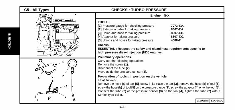
118
INJE
CT
ION
CHECKS : TURBO PRESSUREEngine : 4HX
TOOLS.[1] Pressure gauge for checking pressure 7073-T.A.[2] Extension cable for taking pressure 8607-T.A[3] Union and hose for taking pressure 8607-T.B.[4] Adaptor for taking pressure 8607-T.C.[5] Unions and hoses for taking pressure 4088-T
Checks.ESSENTIAL : Respect the safety and cleanliness requirements specific to high pressure diesel injection (HDi) engines.
Preliminary operations.Carry out the following operations: Remove the screw (1).Disconnect the tube (2).Move aside the pressure sensor (3).
Preparation of tools : in position on the vehicle.Fit as follows : Remove the hose (a) of tool [5] , screw in its place the tool [3] , remove the hose (b) of tool [5] ,screw the hose (b) of tool [5] on the pressure gauge [1] , screw the adaptor [4] onto the tool [5].Connect the tube (2) of the pressure sensor (3) on the tool [4] , tighten the tube (2) with aSerflex type collar.
B1BP28DC E5AP1SUC
C5 - All Types

119
INJE
CT
ION
B1BP28EC C5FPOBLC
CHECKS : TURBO PRESSUREEngine : 4HX
Preparation of tools : in position on the vehicle (continued).Screw the tool [3] on the take-off of the turbo air radiator at «c».Place the pressure gauge on the cup holder at «d.».Connect the extension [2] on the hose «b» and tool [5].
ESSENTIAL : Observe the following checking requirements.
- Start the engine.- Engage first gear and start the vehicle.- Engage the gears up to third gear.- Decelerate to 1500 rpm .Accelerate gradually : the pressures should be the following :
1.1 ± 0.05 b at 2000 rpm 1.2 ± 0.05 b at 3000 rpm.
Return the vehicle to normal.Remove the tools [1] , [2] , [3] , [4] and [5] .Reposition the pressure sensor (3).Couple the tube (2).Refit and tighten the screw (1).
C5 - All Types

120
INJE
CT
ION
SPECIFICATIONS OF THE SIEMENS INJECTION PUMP
PUMP -TYPE - REFERENCE
Emission standard
Equipment
L3 / L4
C5 10DW
RHY
RHS
RHZ
SIEMENS 5WS 40001
Transponder
C5 - All Types

121
INJE
CT
ION
SPECIFICATIONS OF THE SIEMENS INJECTION PUMP
PUMP -TYPE - REFERENCE
Emission standard
Equipment
L3 / L4
SYNERGIE 10DW RHZ CP1 (*)
Transponder
SYNERGIE
(*) = The fuel high pressure pump is driven by the timing belt.

122
INJE
CT
ION
FITTING BOSCH INJECTORS
Engines : RHY - RHZ
Evolution : Classification of diesel injector carriers
SYNERGIE
Reminder : RHY and RHZ are equipped with 4 diesel injector carriers marked according to theirinjection duct diameters (flow of diesel fuel).
Identification.The injector carriers have an engraving or paint mark on the upper part of the coil, close to the dieselfuel return aperture :
Mark 1 = BLUE paint mark = Injector class 1.Mark 2 = GREEN paint mark = Injector class 2.
Identification marking:a : Supplier identification.b : PSA identification no.c : Identification of class.
After Sales operations.
ESSENTIAL : When changing a diesel injector carrier, order a component of the same class.
# 15/11/98 (RPO No.) (injector carrier without marking), always order a class 2 injector carrier.B1HP16PC
16/11/98 #

123
ALL
UM
AG
E
1.8I 16V 6FZFR8ME REC94CL RFN52HZ
2.0i 16v RFN 2.75 ± 0.2
2.0i HPi RLZ ZR8TPP15 1 mm
3.0i 24S XFX FGR8MQPE 2.25 ± 0.2
2.0i 16v RFN FR8ME REC9YCL RFN52H2 2.75 ± 0.2
SPARKING PLUGS
Vehicles - Models BOSCHEnginetype
CHAMPION EYQUEMElectrode
gap
Tighteningtorque
(m.daN)
C5
SYNERGIE - C5
SYNERGIE

124
EM
BR
AYAG
EB
VT
RA
NS
MIS
SIO
N
SPEEDOMETER
An E.E.C. decree of 25 June 1976 , regulates the speed displayed by the speedmeter in relation to the actual speed travelled.
This decree stipulates :
- The speed indicated by a speedometer must never be lower than the actual vehicle speed.- Between the speed displayed «SD» and the speed travelled «ST», there must always be the following relationship :
VR < VL < 1.10 VR + 4 Km/h
Example : For an actual speed of 100 Kph the speed displayed by the speedometer may be between 100 and 114 Kph .The speed indicated by the speedometer may be influenced by :
- The speedometer.- The tyres fitted to the vehicle.- The final drive ratio.- The speedometer drive ratio.Any of these components can be checked without removing them from the vehicle. (See information note N° 78-85 TT of 19 October 1978).NOTE : Before replacing the speedometer, check the conformity of the following points :- The tyres fitted to the vehicle.- The gearbox final drive ratio.- The speedometer drive ratio.
ALL TYPES

CLU
TC
HG
EA
RB
OX
DR
IVE
SH
AF
TS
125
CLUTCH SPECIFICATIONS
Engine type
Gearbox type
Supplier
Mechanism / type
Clutch disc
Ø of lining. Ext/Int
Quality of lining
Petrol
1.8i 16V 2.0i 16V 2.0 HPi 3.0i V6
6FZ RFN RLZ XFX
BE4/5 ML/5
VALEO
230 DNG 4700 230 DING 4700 230 DNG 4700 R 242 T 6500
11 R 10X 12 R 14X 11 R 14X 11 A 14X
228/155 242/162
F 808 F 410 F 808 DS F 410
228 D 7312 R 14 X

CLU
TC
HG
EA
RB
OX
DR
IVE
SH
AF
TS
126
CLUTCH SPECIFICATIONS
Engine type
Gearbox type
Supplier
Mechanism / type
Clutch disc
Ø of lining. Ext/Int
Quality of lining
Diesel
2.0 HDi 2.2 HDi
RHY RHS RHZ 4HX
BE4/5 ML/5
LUK
230 P 4700 225 T 5700 242 T 6500
Damping performed by engine flywheel
228/155 225/150 242/162
F 408 F 808

CLU
TC
HG
EA
RB
OX
DR
IVE
SH
AF
TS
127
BE4/5 GEARBOX CONTROL SPECIFICATIONSEngines : 6FZ - RFN - RLZ - RHY
B2CP3CJD
Gear controls
[1] Gear lever positioning tool 8605-T.
(1) Gear engagement ball-joint Ø 10 mm .(2) Gear control lever(3) Gear engagement control cable.(4) Gear selection control cable.(5) Cable selection locking ley.(6) Gear selection ball-joint Ø 10 mm .
C5 - All Types

CLU
TC
HG
EA
RB
OX
DR
IVE
SH
AF
TS
128
BE4/5 GEARBOX CONTROL SPECIFICATIONSEngines : 6FZ - RFN - RLZ - RHY
Gear selection control cable. Gear engagement control cable.
B2CP3CKD B2CP3CLD
Left hand drive Right hand drive Left hand drive Right hand drive
Length A 730 ± 3mm Length G 700 ± 3 mm
Length B 937.5 ± 7.5mm Length H 983 ± 7.5 mm
Note : See adjustment - page 129.
C5 - All Types
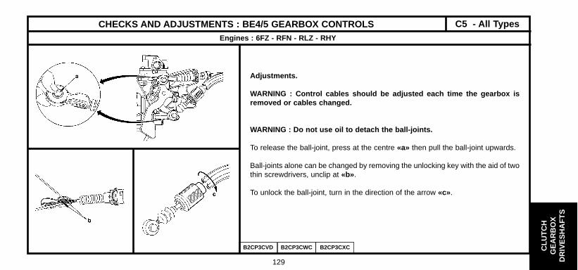
CLU
TC
HG
EA
RB
OX
DR
IVE
SH
AF
TS
129
CHECKS AND ADJUSTMENTS : BE4/5 GEARBOX CONTROLSEngines : 6FZ - RFN - RLZ - RHY
B2CP3CVD B2CP3CWC B2CP3CXC
Adjustments.
WARNING : Control cables should be adjusted each time the gearbox isremoved or cables changed.
WARNING : Do not use oil to detach the ball-joints.
To release the ball-joint, press at the centre «a» then pull the ball-joint upwards.
Ball-joints alone can be changed by removing the unlocking key with the aid of twothin screwdrivers, unclip at «b».
To unlock the ball-joint, turn in the direction of the arrow «c».
C5 - All Types

CLU
TC
HG
EA
RB
OX
DR
IVE
SH
AF
TS
130
CHECKS AND ADJUSTMENTS : BE4/5 GEARBOX CONTROLSEngines : 6FZ - RFN - RLZ - RHY
Tools.
[1] Tool for positioning the gearbox control lever 8605-T Toolkit 9040-T
Adjustments.Cables should be adjusted each time the gearbox, gear controls or power unit are removed
Adjustment principles : - Lock the gear lever in neutral position, using tool [1] .- Position the gearbox in neutral.- Anchor the ball-joints on the gearbox levers.- Lock the cable lengths with the ball-joint locking keys.
Inside the vehicle.- Remove the central console (See corresponding operation).- Remove the plastic blank at (a).- Insert tool [1] fully and rotate a quarter turn to lock the gear control lever.- At neutral.
B2CP3E7C
C5 - All Types

CLU
TC
HG
EA
RB
OX
DR
IVE
SH
AF
TS
131
CHECKS AND ADJUSTMENTS : BE4/5 GEARBOX CONTROLSEngines : 6FZ - RFN - RLZ - RHY
Adjustments (continued)
Under the bonnet.- Remove the air filter assembly.- Unlock the gear engagement cable ball-joint (b).- Unlock the gear selection cable ball-joint (c).- Make sure the gear levers (engagement and selection) are in neutral position.- Lock the cable lengths with the ball-joint locking keys.- Remove the tool [1] .
Checks.
- Remove the tool [1].- Check that all the gears engage without «tightness» .- Check that the gear lever moves identically forwards and backwards and to right and left. If not :- Repeat the adjustment.
Refit the console and the air filter assembly.
B2CP3E8C B2CP3E9C
C5 - All Types

CLU
TC
HG
EA
RB
OX
DR
IVE
SH
AF
TS
132
ML/5 GEARBOX SPECIFICATIONEngines : XFX - RHZ - RHS - 4HX
B2CP3CQD
[1] Gear lever positioning tool 8605-T.
(1) Gear engagement ball-joint Ø 10 mm .(2) Gear control lever(3) Gear engagement control cable.(4) Gear selection control cable.(5) Gear selection ball-joint Ø 10 mm.
C5 - All Types

CLU
TC
HG
EA
RB
OX
DR
IVE
SH
AF
TS
133
ML/5 GEARBOX SPECIFICATIONEngines : XFX - RHZ - RHS - 4HX
Gear selection control cable. Gear engagement control cable.
B2CP3CRD B2CP3CSD
Left hand drive Right hand drive Left hand drive Right hand drive
Length A 750 ± 3mm Length C 771 ± 3 mm
Length B 1012 ± 7.5mm Length D 1094 ± 7.5 mm
Note : See adjustment - page 134.
C5 - All Types

CLU
TC
HG
EA
RB
OX
DR
IVE
SH
AF
TS
134
CHECKS AND ADJUSTMENTS : ML/5 GEARBOX CONTROLS Engines : XFX - RHZ - RHS - 4HX
B2CP3CTD B2CP3BYC
Adjustments.
WARNING : Control cables should be adjusted each time the gearbox isremoved or cables changed.
WARNING : Do not use oil to detach the ball-joints.
To release the ball-joint, press at the centre «a» then pull the ball-joint upwards.
Ball-joints alone can be changed by removing the unlocking key with the aid of twothin screwdrivers, unclip at «b».
C5 - All Types

CLU
TC
HG
EA
RB
OX
DR
IVE
SH
AF
TS
135
CHECKS AND ADJUSTMENTS : ML/5 GEARBOX CONTROLS Engines : XFX - RHZ - RHS - 4HX
Tools
[1] Tool for positioning the gearbox control lever 8605-T Toolkit 9040-T
Adjustments.
Cables should be adjusted each time the gearbox, gear controls or power unit are removed.
Adjustment principles : - Lock the gear lever in neutral position, using tool [1].- Position the gearbox in neutral.- Anchor the ball-joints on the gearbox levers.- Lock the cable lengths with the ball-joint locking keys.
Inside the vehicle.- Remove the central console (See corresponding operation).- Remove the plastic blank at (a).- Insert tool [1] fully and rotate a quarter turn to lock the gear control lever.- At neutral.
B2CP3E7C
C5 - All Types

CLU
TC
HG
EA
RB
OX
DR
IVE
SH
AF
TS
136
CHECKS AND ADJUSTMENTS : ML/5 GEARBOX CONTROLS Engines : XFX - RHZ - RHS - 4HX
Adjustments (continued)
Under the bonnet.
- Remove the air filter assembly.- Unlock the gear engagement and selection cable ball-joint (b).- Make sure the gear levers (engagement and selection) are in neutral position.- Lock the cable lengths with the ball-joint locking keys.- Remove the tool [1].
Checks.
- Remove the tool [1].- Check that all the gears engage without «tightness ».- Check that the gear lever moves identically forwards and backwards and to right and left. If not :- Repeat the adjustment.- Refit the console and the air filter assembly.
B2CP3EBC
C5 - All Types

CLU
TC
HG
EA
RB
OX
DR
IVE
SH
AF
TS
137
BE4/5 GEARBOX CONTROL SPECIFICATIONS
Engines : RFN
(1) Gear control lever
(2) Gear engagement control cable (*)
(3) Gear selection control cable (*)
(4) Gear selection ball-joint Ø 10 mm.
(5) Gear engagement ball-joint Ø 10 mm.
(6) Flexible insulating grommet through the bulkhead.
(*) = These two cables cannot be separated.
B2CP3BWD
SYNERGIE

CLU
TC
HG
EA
RB
OX
DR
IVE
SH
AF
TS
138
CHECKS AND ADJUSTMENTS : BE4/5 GEARBOX CONTROLSEngines : RFN
Principles of adjusting the gear controls.
WARNING : Cables should be adjusted each time the gearbox,gear controls or power unit are removed.
Principles.
Lock the gear lever in neutral position, using tool:9607-T.
Place the gearbox in neutral.
Couple the cables on the lever.
Fit the ball-joints on the gearbox lever.
Lock the cable lengths with the ball-joint locking keys.
WARNING : Do not use any tool to unclip theball-joints.
To unlock the ball-joint, press at the centre «a»,then pull the ball-joint upwards.
NOTE : Changing an individual ball-joint is possibleas long as the locking key is removed.
Unclip at «b», using two small screwdrivers.
SYNERGIE
B2CP3BXC B2CP3BYC

CLU
TC
HG
EA
RB
OX
DR
IVE
SH
AF
TS
139
CHECKS AND ADJUSTMENTS : BE4/5 GEARBOX CONTROLS
TOOLS :[1] Tool for positioning the gear lever : 9607-T.
ADJUSTMENTS.
WARNING : Cables should be adjusted each timethe gearbox, gear controls or power unit are removed.
Inside the vehicle.- Remove the trim under the gear lever.- Lock the gear lever in neutral position,using tool [1] .
Under the bonnet.- Remove the air filter assembly.- Unlock the ball-joint keys at «a».- Place the gear selection and control levers neutral.- Lock the cable lengths with the ball-joint locking
keys.
CHECKS.
- Remove the tool [1] .- Check that all the gears engage without
«tightness » .- Check that the gear lever moves identicallyforwards and backwards and to right and left. If itdoes not, repeat the adjustment.
- Refit the trim under the gear lever.- Refit the air filter assembly.
Adjusting the gear controls.
Engines : RFN
SYNERGIE
B2CP3C6C B2CP3C0C
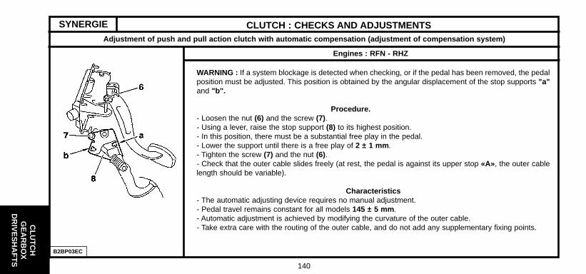
CLU
TC
HG
EA
RB
OX
DR
IVE
SH
AF
TS
140
CLUTCH : CHECKS AND ADJUSTMENTS
WARNING : If a system blockage is detected when checking, or if the pedal has been removed, the pedalposition must be adjusted. This position is obtained by the angular displacement of the stop supports "a"and "b".
Procedure.- Loosen the nut (6) and the screw (7).- Using a lever, raise the stop support (8) to its highest position.- In this position, there must be a substantial free play in the pedal.- Lower the support until there is a free play of 2 ± 1 mm .- Tighten the screw (7) and the nut (6).- Check that the outer cable slides freely (at rest, the pedal is against its upper stop «A», the outer cablelength should be variable).
Characteristics- The automatic adjusting device requires no manual adjustment.- Pedal travel remains constant for all models 145 ± 5 mm .- Automatic adjustment is achieved by modifying the curvature of the outer cable.- Take extra care with the routing of the outer cable, and do not add any supplementary fixing points.
Engines : RFN - RHZ
B2BP03EC
Adjustment of push and pull action clutch with automatic compensation (adjustment of compensation system)
SYNERGIE

CLU
TC
HG
EA
RB
OX
DR
IVE
SH
AF
TS
141
CLUTCH : CHECKS AND ADJUSTMENTS
NOTE : This cable has an automatic adjusting device which takes up the clutch disc wear and makes up for the compression of the outer cable.
DESCRIPTION1 - Metallic cable, crimped on both ends. 5 - Tensioning spring ensuring the maximum length of the outer cable.2 - Outer cable or telescopic duct. 6 - Wear take up device.3 - Outer cable stop, bulkhead side (fixed point on the bodyshell). 7 - Attaching end-piece.4 - Outer cable stop, gearbox side (fixed point on the gearbox).
Engines : RFN - RHZ
B2BP02SC
SYNERGIE
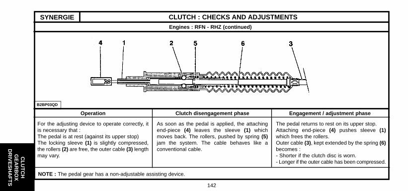
CLU
TC
HG
EA
RB
OX
DR
IVE
SH
AF
TS
142
CLUTCH : CHECKS AND ADJUSTMENTS
B2BP03QD
For the adjusting device to operate correctly, itis necessary that :The pedal is at rest (against its upper stop)The locking sleeve (1) is slightly compressed,the rollers (2) are free, the outer cable (3) lengthmay vary.
Engines : RFN - RHZ (continued)
As soon as the pedal is applied, the attachingend-piece (4) leaves the sleeve (1) whichmoves back. The rollers, pushed by spring (5)jam the system. The cable behaves like aconventional cable.
The pedal returns to rest on its upper stop.Attaching end-piece (4) pushes sleeve (1)which frees the rollers.Outer cable (3), kept extended by the spring (6)becomes :- Shorter if the clutch disc is worn.- Longer if the outer cable has been compressed.
Operation Clutch disengagement phase Engagement / adjustment phase
NOTE : The pedal gear has a non-adjustable assisting device.
SYNERGIE

CLU
TC
HG
EA
RB
OX
DR
IVE
SH
AF
TS
143
CLUTCH : CHECKS AND ADJUSTMENTS
B2BP03RC E5AP14VC B2BP03SC
Hydraulically operated pull-action clutch (Non-adjustable)
(1) Quick-fit union: Tool 9040-T.H.
Synergie : RHZ GearboxEngine ML/5
SYNERGIE

CLU
TC
HG
EA
RB
OX
DR
IVE
SH
AF
TS
144
CLUTCH : CHECKS AND ADJUSTMENTS
A Old assembly, supplied complete and filled with hydraulicfluid.B New assembly : - The components supplied separately.- The circuit is filled with fluid after being fitted to the vehicle.(1) Clutch master cylinder.(2) Clutch slave cylinder.(3) Hydraulic clutch control reservoir.(4) Link pipe.(5) Click-fit union, sealed (after dismantling).(6) Click-fit union, non-sealed (after dismantling).(7) Bleed screw.The new assembly consists of the the following parts : - Clutch master cylinder, anchored in place after a 1/4 turn.- Clutch slave cylinder, with push-rod.- Hydraulic clutch control reservoir, with feed pipe.- Link pipe, between master cylinder and slave cylinder.
Hydraulically operated pull-action clutch (Non-adjustable)
Engine : RHZ
B2BP03ZD
SYNERGIE

CLU
TC
HG
EA
RB
OX
DR
IVE
SH
AF
TS
145
SYNERGIECLUTCH : CHECKS AND ADJUSTMENTS
After fitting on the vehicle, the circuit should be filled with a«DOT 4» type brake fluid.Clutch control reservoir capacity 120 cc.(Bleeding is carried out not under pressure).Repair.The new clutch control components are not compatible with theold parts.Both the old and the new components are marketed by«Replacement Parts ».Draining – Filling - Top-up.- Check the level after each repair visit.- Fill the circuit (after drainage), using a filling cylinderspecifically designed for this operation.- Use the circuit’s bleed screw (7).- The level of fluid inside the clutch control reservoir should bebetween the min. and max. marks.NOTE : Wear on the clutch causes a slight increase in the levelof fluid inside the control reservoir.
Hydraulically operated pull-action clutch (Non-adjustable)
Engines : RHZ
B2BP03ZD

CLU
TC
HG
EA
RB
OX
DR
IVE
SH
AF
TS
146
ML/5 GEARBOX CONTROLS
B2CP16FP
Engine : RHZ
SYNERGIE

CLU
TC
HG
EA
RB
OX
DR
IVE
SH
AF
TS
147
GEARBOX AND TYRE SPECIFICATIONS
Engine type
Tyres-Rolling circumference
Speedometer ratio
Gearbox type
Gearbox ident. plate
Reduction box torque
Engine type
Tyres-Rolling circumference
Speedometer ratio
Gearbox type
Gearbox ident. plate
Reduction box torque
Petrol
Petrol
18i 16V 2.0i 16V 2.0 HPi
Automatic Automatic6FZ RFN RLZ
195/65 R15 – 1.93 m 195/65 R15 – 1.93 m
BE4/5 AL4 BE4/5 AL4 BE4/5
20 DL 29 20 TP 44 20 DL 30 20 TP 42 20 DL 31
19x79 21x73 19x79 23x73 19x77
22x18 52x67 22x18 52x67 None
3.0i V6
Automatic
XFX
215/55 R16 – 1.96 m
ML/5C ML/5T 4 HP 20
20 LE 95 20 LE 95 20 HZ 13
16x65 20x69
None 59x68
C5 - All Types

CLU
TC
HG
EA
RB
OX
DR
IVE
SH
AF
TS
148
GEARBOX AND TYRE SPECIFICATIONS
Engine type
Tyres-Rolling circumference
Speedometer ratio
Gearbox type
Gearbox ident. plate
Reduction box torque
Engine type
Tyres-Rolling circumference
Speedometer ratio
Gearbox type
Gearbox ident. plate
Reduction box torque
Diesel
Diesel
2.0 HDi 2.2 HDiAutomatic
RHY RHS - RHZ 4HX
195/65 R15 – 1.93 m 215/65 R16-1.96 m
BE4/5 ML/5C ML/5T AL4 ML/5C
20 DL 32 20 LM 18 20 LE 94 20 TP 43 20 LM 17
19x75 16x65 25x68 17x67
None None 52x67 None
2.2 HDi
Automatic
4HX
215/65 R16-1.96 m
ML/5T 4 HP 20
20 LE 96 20 HZ 20
17x67 23x66
None 59x68
C5 - All Types

CLU
TC
HG
EA
RB
OX
DR
IVE
SH
AF
TS
149
2.0i 16V 2.0 HDi
RFN RHY
205/65 R15 - 1.97 m
BE4/5 AL4 ML/5
20 DL 26 20 DL 27 20 TP 31 20 LE 91 (*)
14x62 21x73 15x67
18x14 20x16 25x20
GEARBOX AND TYRE SPECIFICATIONS
Engine type
Tyres-Rolling circumference
Speedometer ratio
Gearbox type
Gearbox ident. plate
Reduction box torque
DieselPetrol
SYNERGIE
Automatic
(*) DVA = Double Damped Flywheel
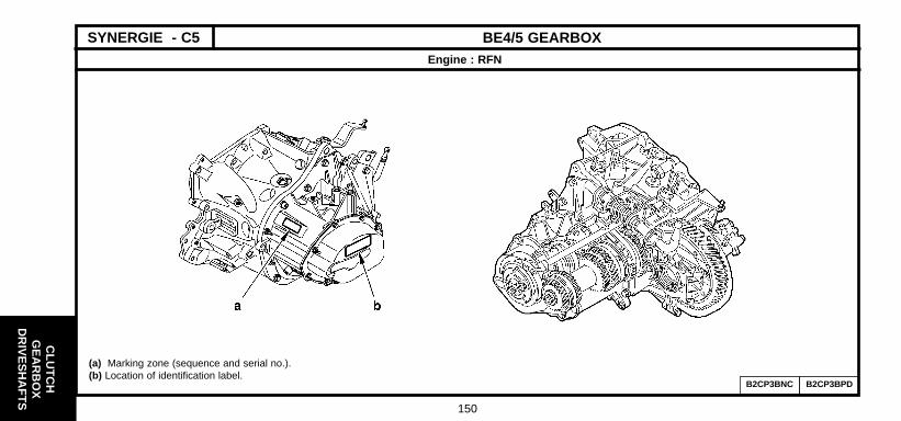
CLU
TC
HG
EA
RB
OX
DR
IVE
SH
AF
TS
150
BE4/5 GEARBOXEngine : RFN
B2CP3BNC B2CP3BPD
SYNERGIE - C5
(a) Marking zone (sequence and serial no.).(b) Location of identification label.

CLU
TC
HG
EA
RB
OX
DR
IVE
SH
AF
TS
151
BE4/5 GEARBOXEngine : RFN
Description
(1) Primary shaft.
(2) Clutch bearing guide.
(3) Gearbox casing.
(4) Clutch housing.
(5) Reverse idle.
(6) Drive gear (3rd gear).
(7) 3rd /4th gear synchroniser
(8) Drive gear (4th gear).
(9) Drive gear (5th gear).
(10) 5th gear synchroniser.
(11) Driven gear (5th gear).
(12) Driven gear (2nd / 4th gear )
(13) Driven gear (2nd gear).
(14) 1st / 2nd gear synchroniser
(15) Driven gear (1st gear).
(16) Secondary shaft.
(17) Differential gear.
(18) Satellite gears.
(19) Planet gears.
(20) Differential housing.
(21) Speedometer drive.
(22) Extension.
« d » Adjusting shims : 0,7 to 2,4 mm.(From 0,10 to 0,10 mm)
« c » Adjusting shims : 1,4 to 1,6 mm.(From 0,10 to 0,10 mm)
B2CP3BQP
SYNERGIE - C5

CLU
TC
HG
EA
RB
OX
DR
IVE
SH
AF
TS
152
BE4/5 GEARBOXEngine : RFN
Tightening torques
Ref. Description Number of screws m.daN
1 End guide 3 1.2 ± 0.1
2 Clutch housing 13 1.3 ± 0.1
3 Primary shaft nut 1 7.2 ± 0.7
4 Secondary shaft nut 1 6.5 ± 0.7
5 Yoke holding screw 2 1.5 ± 0.1
6 Differential gearwheel screw 2 6.5 ± 0.7
Reverse gear contact 1 2.5 ± 0.3
7 Differential housing 4 5 ± 0.5
8 Breather pipe 1 1.7 ± 0.2
9 Rear housing cover screw 7 1.2 ± 0.1
10 Top-up plug 1 2.2 ± 0.2
11 Differential housing screw 4 1.2 ± 0.1
12 Drain plug screw 1 3.5 ± 0.4
B2CP3BSP
B2CP3BTD
SYNERGIE - C5
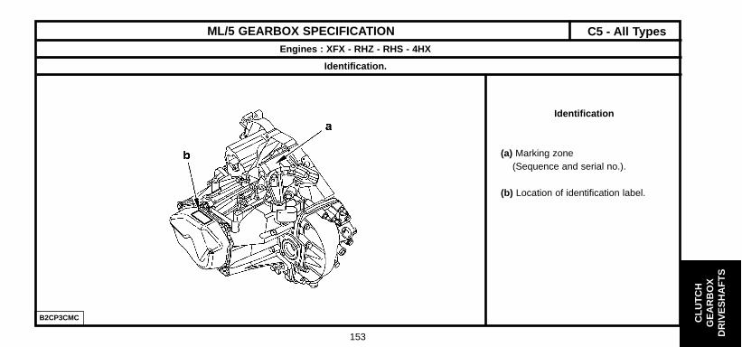
CLU
TC
HG
EA
RB
OX
DR
IVE
SH
AF
TS
153
ML/5 GEARBOX SPECIFICATIONEngines : XFX - RHZ - RHS - 4HX
Identification.
Identification
(a) Marking zone (Sequence and serial no.).
(b) Location of identification label.
B2CP3CMC
C5 - All Types

CLU
TC
HG
EA
RB
OX
DR
IVE
SH
AF
TS
154
ML/5 GEARBOX SPECIFICATIONEngines : XFX - RHZ - RHS - 4HX
Identification (continued)
(1) Primary shaft.(2) Clutch bearing guide.(3) Clutch housing(4) Gearbox casing.(5) Oil channel(6) Primary shaft bearing adjustmentshim.(7) Drive gear (5th)(8) Secondary shaft.(9) Driven gear (1st)(10) Satellite gears.(11) Speedometer screw.(12) Speedometer drive.(13) Planet gears.(14) Differential housing(15) Differential gearwheel.(16) Differential bearing stop plate.(17) 1st/2nd gear synchroniser andreverse gear driven gear.
(18) Driven gear (2nd)(19) Driven gears (3rd)(20) 3rd/4th gear synchroniser. (21) Driven gears (4th)(22) Driven gears (5th)(23) 5th gear synchroniser. (24) Planet gear adjustment shim.
Tightening torques m.daN.
(25) Clutch bearing guide 2 ± 0,2(26) Secondary shaft nut 17 ± 1,5(27) Differential screw 7,5 ± 0,5
B2CP3CNP
C5 - All Types

CLU
TC
HG
EA
RB
OX
DR
IVE
SH
AF
TS
155
ML/5 GEARBOX SPECIFICATIONEngines : XFX - RHZ - RHS - 4HX
Identification (continued)
B2CP3CPD
Tightening torques m.daN.
(28) Reverse lamp switch 2,5 ± 0,2(29) Gearbox casing /clutch housing fixing screws 2 ± 0,2(30) Differential bearing stop plate screws 2 ± 0,2(31) Gearbox rear casing screws 2 ± 0,2(32) Drain plug 3 ± 0,3(33) Filling / top-up plug 3 ± 0,3(34) M8 screw (Differential housing fixing) 2 ± 0,2(35) M10 screw (Differential housing fixing) 4 ± 0,5(36) Selector guide screw 4 ± 0.5
C5 - All Types

CLU
TC
HG
EA
RB
OX
DR
IVE
SH
AF
TS
156
ML/5 GEARBOX SPECIFICATIONEngines : XFX - RHZ - RHS - 4HX
Recommendations - Precautions
B2CP3CUC
(1) Drain plug.(2) Filler and top-up plug.
Oil quality.- See chapter on lubricants: page 19.
Oil quantity.- After draining = 1.8 litres
C5 - All Types

CLU
TC
HG
EA
RB
OX
DR
IVE
SH
AF
TS
157
4 HP 20 AUTOACTIVE GEARBOX SPECIFICATIONEngines : XFX - 4HX
B2CP3CYD
Identification.
(1) Identification plate(riveted on the casing).
(a) Serial no.
(b) ZF number.(last digits taken into account)
(c) Type of automatic gearbox.
(d) Component reference
Oil quality and quantity (See chapter, page 19).
C5 - All Types

CLU
TC
HG
EA
RB
OX
DR
IVE
SH
AF
TS
158
4 HP 20 AUTOACTIVE GEARBOX SPECIFICATIONEngines : XFX - 4HX
Tightening torques m.daN.
Gearbox exterior.
(2) Oil channel union fixing Exteror fixing of 2.5 ± 0.5(3) Exterior fixing of converter cover on clutch housing 2.3 ± 0.5(4) Speedometer take-off aperture plug 1 ± 0.1(5) Steel casing fixing 0.6 ± 0.1(6) Converter fixing on engine 6 ± 1(7) Interior fixing of converter cover on clutch housing 2.3 ± 0.5(8) Torx fixing of converter cover on clutch housing 2.3 ± 0.5
Drain plug 4.5 ± 0.8Heat exchanger fixing 3.5 ± 0.5Selector lever position switch fixing 1 ± 0.2Converter cover fixing on engine cover (XFX engine) 6.5 ± 1Converter cover fixing on engine cover (4HX engine) 5.8 ± 1
B2CP3CZC B2CP24BC B2CP24CC
C5 - All Types

CLU
TC
HG
EA
RB
OX
DR
IVE
SH
AF
TS
159
4 HP 20 AUTOACTIVE GEARBOX SPECIFICATIONEngines : XFX - 4HX
Tightening torques m.daN.
Gearbox interior.
(9) Input speed sensor fixing 0.8 ± 0.1(10) Hydraulic block fixing (Large head) 0.8 ± 0.1(11) Output speed sensor fixing 1 ± 0.2
B2CP24DC B2CP24EC
C5 - All Types

CLU
TC
HG
EA
RB
OX
DR
IVE
SH
AF
TS
160
RECOMMENDATIONS - PRECAUTIONS (AL 4 and 4 HP 20 AUTOMATIC GEARBOXES)Engines : 6FZ - RFN - RHZ - XFX - 4HX
Towing.The front of the vehicle must be raised in order to be towed.If the front of the vehicle cannot be raised :IMPERATIVE : - Put gear lever in position «N».- Do not add any oil.
AL4 gearbox- Do not exceed 50 km/h (30mph) over a distance of 50 km (30m).4 HP 20 gearbox- Do not exceed 70 km/h (45mph) over a distance of 100 km (60m).
Driving.Never drive with the ignition switched off.Never push the vehicle to try to start it;(impossible with an automatic gearbox).LubricationThe automatic gearbox is only lubricated when the engine is running.
REMOVING - REFITTING. (Automatic gearbox).
WARNING : Never place the gearbox on its lower casing(risk of deforming the tray and damaging the hydraulic valve block).Never use the connections as handles for raising, turning, holding orpushing the gearbox.
ESSENTIAL : - Fit the converter retaining peg while the gearbox is removed.- Fit the centring peg to locate the gearbox on the engine:(remove the converter retaining peg just before locating)
WARNING : With the emergency programme selected, an impact isfelt when changing from ‘‘P’’ ‘‘R’’ ou ‘‘N’’ ‘‘R’’ .
Precautions to be taken
C5 - All Types

CLU
TC
HG
EA
RB
OX
DR
IVE
SH
AF
TS
161
RECOMMENDATIONS - PRECAUTIONS (AL 4 AUTOMATIC GEARBOX)Engines : 6FZ - RFN - RHZ
Procedure to be followed prior to carrying out repairs on AL4 autoactive gearbox
If a gearbox malfunction occurs, there are two possible configurationsdepending on the seriousness of the fault : - Gearbox in back-up mode with a replacement programme of (the faultvalues are taken in substitution).- Gearbox in back-up mode with an emergency programme (3rd hydraulic)WARNING : In the emergency programme, an impact is felt whenchanging P/R, N/R and N/D.Réception client.Discuss with the customer, to find out all the malfunction symptoms..Oil quality – Oil level.Oil quality.If the gearbox has suffered a serious fault resulting in a malfunction or thedestruction of a clutch, the oil will overheat and become contaminated withimpurities : the oil is said to be «burnt» .This is characterised by a black colour and the presence of an unpleasantsmell.ESSENTIAL : The gearbox must be replaced.
Oil level.See corresponding operation.An excessive oil level can result in the following consequences : - Excessive heating of the oil.- Oil leaks.An insufficent level causes the destruction of the gearbox.Top up the level of oil in the gearbox (if necessary).Check using a diagnostic tool.Read the fault codes (engine and gearbox).Absence of fault codes.Carry out parameter measures, actuator tests and a road test.Presence of fault codes.Carry out the necessary repairs.Delete the fault codes.Carry out a road test to check the repair and, if need be, modify thegearbox ECU parameters (this is essential after an initialisation of theECU).
C5 - All Types

CLU
TC
HG
EA
RB
OX
DR
IVE
SH
AF
TS
162
RECOMMENDATIONS - PRECAUTIONS (AL 4 and 4 HP 20 AUTOMATIC GEARBOXES)Engines : 6FZ - RFN - RHZ - XFX - 4HX
Procedure prior to carrying out repairs (continued)
When the ECU detects an erroneous or non-existent valueon input or output :
- It writes the fault in memory.- For each associated context, it writes the context of the oldest fault
in memory.- It initiates a back-up mode strategy.
There are two types of back-up modes :
- The ECU makes replacement values available (relating to comfort,gear selection quality, loss of functions).
- Access to emergency programme (only 3rd ratio and reverse areavailable)
NOTE : 4 HP 20 : A snatching may be felt when changing : P/R - N/R - N/D.
Reading the fault codes.Read the fault codes.
No fault codes present :Carry out a measure of parameters.
Anomalies present :• YES : Carry out the necessary repairs.• NO : Read the fault codes – engine ECU- Carry out a road test.
Following an initialisation of the ECU, for a certain period of time theremay be an inconsistent gear selection quality (while ECU parametersare adapted to the gearbox).To achieve a consistent standard, it is necessary to carry out a road testtaking in frequent gear changes (auto-adaptive laws).
C5 - All Types

CLU
TC
HG
EA
RB
OX
DR
IVE
SH
AF
TS
163
RECOMMENDATIONS - PRECAUTIONS (AL 4 and 4 HP 20 AUTOMATIC GEARBOXES)Engines : 6FZ - RFN - RHZ - XFX - 4HX
ECU : Downloading, Configuration, Initialisation (Pedal).
Downloading. (AL 4 and 4 HP 20)Updating the gearbox ECU by downloading :- Follow the procedure using the diagnostic equipment.
The operation of downloading is used to update the automatic gearbox ECU or to adapt it to evolutions of the engine ECU.After downloading, carry out the following :- Note down the value in the oil usage counter present in the automatic gearbox ECU.- Delete the fault codes.- Again note down the value in the oil usage counter and compare it with the value previously read.- Pedal initialisation (AL 4)- Configuration (if needed) (AL 4) Following the di agnostic tool procedure.- A reinitialisation of the autoadaptives (AL4 and 4 HP 20).- A road test (AL 4 and 4 HP 20).
IMPERATIVE : Every update of the automatic gearbox ECU mustbe accompanied by an update of the engine ECU.
C5 - All Types

CLU
TC
HG
EA
RB
OX
DR
IVE
SH
AF
TS
164
RECOMMENDATIONS - PRECAUTIONS (AL 4 AUTOMATIC GEARBOX)Engines : 6FZ - RFN - RHZ
ECU : Downloading, Configuration, Initialisation (Pedal) (continued)
Downloading (AL 4 only).
ECU downloading procedure :- Follow the diagnostic tooling procedure.
A new ECU or downloaded update is always configured with thefollowing options :- SHIFT LOCK gear selection lever position.- OBD outlet (emission standard L4).
If the ECU is to be fitted to a vehicle without one or both of theseoptions:- Carry out a configuration which inhibits the diagnosis of the option(s)concerned.
Pedal initialisation. (AL 4 only).
A pedal initialisation must be carried out in the following cases :
- Replacement of the automatic gearbox ECU.
- Replacement of the automatic gearbox.
- Downloading of the ECU configuration.
- Adjustment or replacement of the accelerator cable.
- Replacement of the throttle potentiometer.
C5 - All Types
- IMPERATIVE : For a certain period of time, while the ECU parameters are adapted to the gearbox, there may be an inconsistent gearselection quality. To achieve a consistent standard, it will be necessary to carry out a road test taking in frequent gear chan ges(auto adaptive laws).

CLU
TC
HG
EA
RB
OX
DR
IVE
SH
AF
TS
165
RECOMMENDATIONS - PRECAUTIONS (4 HP 20 AUTOMATIC GEARBOX)Engines : XFX - 4HX
SHIFT LOCK
The shift lock is a system which locks the gear selection lever in the park position «P».Unlocking the «shift lock» (normal operation).Switch on the ignition.Apply the brake pedal and keep it pressed.Using the selection lever, disengage from position «P».Unlocking the «shift lock» (with a fault).NOTE : It is impossible to unlock the «shift lock» with the « normal operation» method.The causes of the fault may arise from the following components : - «Shift lock».- Gear lever position switch.- Automatic gearbox ECU.- Electrical harnesses.- Battery voltage.Remove : - The gear lever knob (1) by pulling upwards.- The cover (2) (unclip).- The shutter.Unlock the «shift lock» (4) using a screwdriver.Using the selection lever, disengage from position «P».
C5FPOCUD C5FPOCTC
C5 - All Types
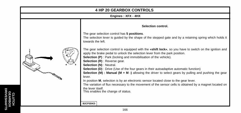
CLU
TC
HG
EA
RB
OX
DR
IVE
SH
AF
TS
166
4 HP 20 GEARBOX CONTROLSEngines : XFX - 4HX
Selection control.
The gear selection control has 5 positions .The selection lever is guided by the shape of the stepped gate and by a retaining spring which holds ittowards the left.
The gear selection control is equipped with the «shift lock» , so you have to switch on the ignition andapply the brake pedal to unlock the selection lever from the park position.Selection (P) : Park (locking and immobilisation of the vehicle).Selection (R) : Reverse gear.Selection (N) : Neutral.Selection (D) : Drive (Use of the four gears in their autoadaptive automatic function)Selection (M) : Manual (M + M -) allowing the driver to select gears by pulling and pushing the gearlever.In position M, selection is by an electronic sensor located close to the gear lever.The variation of flux necessary to the movement of the sensor cells is obtained by a magnet located onthe lever itself.This enables the change of status.
B2CP3DKD

CLU
TC
HG
EA
RB
OX
DR
IVE
SH
AF
TS
167
4 HP 20 GEARBOX CONTROLSEngines : XFX - 4HX
Selection control (continued).
In position M, selection is by an electronic sensor located close to the gear lever.The variation of flux necessary to the movement of the sensor cells is obtained by a magnet located onthe lever itself. This enables the change of status. The information is transmitted to the gearbox ECU.Two switches placed on the gear control gate permit the driver to choose one of the following threedriving programmes: - Normal : The normal programme operates in the absence of the other two (Eco law, autoadaptativemode).- Sport : Permits a more dynamic, sporty performance.- Snow : Facilitates starting and adhesion on slippery surfaces.To return to the normal programme, press a second time on the sport switch or snow switch.
Only when the selector is in position (P) or (N) can the engine be started.- (1) Control linkage with ball-joint.- (2) Automatic adjustment (Push-button « c », pressed in to lock the control adjustment, springs out forthe adjustment to be made).- (3) Cable sleeve stop.The automatic gearbox is controlled by cable.
B3CP3DLC
C5 - All Types
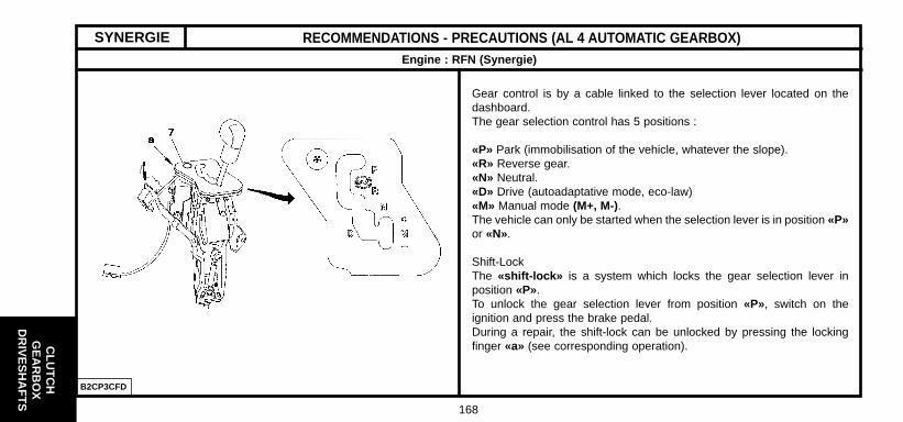
CLU
TC
HG
EA
RB
OX
DR
IVE
SH
AF
TS
168
RECOMMENDATIONS - PRECAUTIONS (AL 4 AUTOMATIC GEARBOX)Engine : RFN (Synergie)
Gear control is by a cable linked to the selection lever located on thedashboard.The gear selection control has 5 positions :
«P» Park (immobilisation of the vehicle, whatever the slope).«R» Reverse gear.«N» Neutral.«D» Drive (autoadaptative mode, eco-law)«M» Manual mode (M+, M-).The vehicle can only be started when the selection lever is in position «P»or «N».
Shift-LockThe «shift-lock» is a system which locks the gear selection lever inposition «P».To unlock the gear selection lever from position «P», switch on theignition and press the brake pedal.During a repair, the shift-lock can be unlocked by pressing the lockingfinger «a» (see corresponding operation).
SYNERGIE
B2CP3CFD

CLU
TC
HG
EA
RB
OX
DR
IVE
SH
AF
TS
169
2 ± 0.2
DRIVESHAFTS - GEARBOX
Tightening torques (m.daN)
Driveshaftbearing
EnginesVehicles Gearbox Right Left Tool kit
Gearbox oil seal mandrels
32.5 ± 1.59017-T.C
0338 J10338 J3
8010-T.D8010-T.K1
7114-T.W
5701-T.A
0338 H10338 H2
8010-T.J8010-T.K2
7116-T
9017-T
0338
8010-T
Driveshaftnut
6FZ - RFN - RLZRHY
XFXRHZ - 4HX
6FZ - RFN - RHZ
XFX - 4HX
BE4/5
ML/5
AL4
4 HP20
C5
SYNERGIE
Tightening torques (m.daN) of the wheel bolts
SYNERGIECITROËN
C5 SteelAluminium
9 ± 0.5
10 ± 0.5
SYNERGIE - C5
7114-T.X

170
ES
SIE
UX
SU
SP
EN
SIO
ND
IRE
CT
ION
AXLE GEOMETRYMeasuring front height
The measurement of the front dimension «H1» is between ground leveland the measuring zone on the front subframe(to the rear of the front yokes fixing the suspension arm).
L1 (mm)Theoretical dimension between the level of the front subframe andthe wheel axis.
140
L2 (mm)Theoretical dimension between the measuring zone on the cross-member support and the wheel axis.
73
Measuring rear height
B3BP166D B3BP168D
C5 - All Types
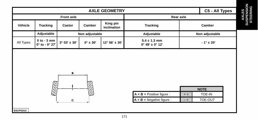
AX
LES
SU
SP
EN
SIO
NS
TE
ER
ING
171
AXLE GEOMETRYFront axle Rear axle
A > B = Negative figure : – = TOE-OUT
A < B = Positive figure : + = TOE-IN
NOTE
Véhicle
All Types
Tracking
Adjustable
0 to - 3 mm0° to - 0° 27'
3° 03' ± 30' 0° ± 30' 12° 56' ± 30'5.4 ± 1.3 mm0° 49’ ± 0° 12’
- 1° ± 20'
Non adjustable Adjustable Non adjustable
Castor CamberKing pin
inclinationTracking Camber
B3CP02UC
C5 - All Types

AX
LES
SU
SP
EN
SIO
NS
TE
ER
ING
172
FRONT AXLE
Tightening torques m.daN.
(1) Suspension leg upper fixing 7 ± 0.7(2) Suspension leg fixing on bodyshell 4.3 ± 0.6(3) Anti-roll bar link rod upper fixing 6.4 ± 0.6(4) Anti-roll bar link rod upper fixing 6.4 ± 0.6(5) Ball-joint fixing 4.5 ± 0.4(6) Ball-joint fixing on pivot 25 ± 2.5(7) Suspension leg upper fixing on pivot 5.4 ± 0.5(8) Hub nut 32.5± 2.6(9) Wheel fixing 9 ± 1(10) Arm front fixing 13 ± 1.3(11) Arm rear fixing 8 ± 0.8(12) Anti-roll bar bearing fixing on subframe 4.2 ± 0.6Stabiliser bar fixing on subframe 6.6 ± 0.6
Anti-roll bar
Engines Diameter (mm) Colour ref.
All types (except ES9J4) 23.5 Yellow
ES9J4 24.5 White
NOTE : The geometry specifications are given with the suspensionspecifications.B3CP05VP B3CP05WD
C5 - All Types

AX
LES
SU
SP
EN
SIO
NS
TE
ER
ING
173
REAR AXLE
Tightening torques m.daN.
(1) Anti-roll bar fixing 13.1± 1.4(2) Rear rubber mounting fixing on bodyshell 8 ± 1.2(3) Rear subframe fixing 11.5 ± 1.1(4) Front subframe fixing on bodyshell 11.5 ± 1.1(5) Suspension shaft fixing 14.9 ± 1.3(6) Hub nut 25 ± 2.5(7) Wheel fixing 9 ± 1
NOTE : (3) and (4) Face and threads not greased .
Anti-roll bar
Engines Diameter (mm) Colour ref.
All types (except ES9J4) 21.5 Blue
ES9J422 Yellow
All types estates
NOTE : The geometry specifications are given with the suspensionspecifications.
B3DP08BD B3DP08CD
C5 - All Types
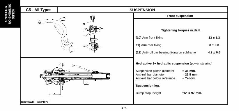
AX
LES
SU
SP
EN
SIO
NS
TE
ER
ING
174
SUSPENSIONFront suspension
Tightening torques m.daN.
(10) Arm front fixing 13 ± 1.3
11) Arm rear fixing 8 ± 0.8
(12) Anti-roll bar bearing fixing on subframe 4.2 ± 0.6
Hydractive 3+ hydraulic suspension (power steering)
Suspension piston diameter = 35 mm .Anti-roll bar diameter = 23,5 mm .Anti-roll bar colour reference = Yellow .
Suspension leg.
Bump stop, height "A" = 97 mm.
B3CP05WD B3BP167D
C5 - All Types

AX
LES
SU
SP
EN
SIO
NS
TE
ER
ING
175
SUSPENSIONRear suspension
Tightening torques m.daN.
(13) Subframe rear fixing 11.5 ± 1.1(14) Rear rubber mounting fixing on bodyshell 8 ± 1.2(15) Anti-roll bar fixing 13.1 ± 1.4(16) Front fixing of subframe on bodyshell 11.5 ± 1.1NOTE : (13) and (16) Face and threads greased.(17)Arm shaft fixing 14.9 ± 1.3(18) Hub nut 25 ± 2.5(19) Wheel fixing 9 ± 1Stabiliser bar fixing on subframe 6.6 ± 0.6
Hydractive 3+ hydraulic suspension (power steering)Suspension piston diameter = 37 mm.Anti-roll bar diameter- Saloon = 21.5 mm- Break = 22 mm.Anti-roll bar colour reference- Saloon = Blue- Estate = Green
B3DP08ND B3DP08PD

AX
LES
SU
SP
EN
SIO
NS
TE
ER
ING
176
SUSPENSION
Height control
Tightening torques m.daN.
(20) Collars 0.6
B3CP06TD
C5 - All Types

AX
LES
SU
SP
EN
SIO
NS
TE
ER
ING
177
AXLE GEOMETRYFront axle Rear axle
A > B = Negative figure : – = TOE-OUT
A < B = Positive figure : + = TOE-IN
NOTE
Véhicle
All Types
Tracking
(Adjustable )
0 to - 3 mm0° to - 0° 27'
3° 03' ± 30' 0° ± 30' 12° 56' ± 30'5.4 ± 1.3 mm0° 49’ ± 0° 12’
- 1° ± 20'
(Non adjustable) (Non adjustable) (Non adjustable)
Castor CamberKing pin
inclinationTracking Camber
B3CP02UC
C5 - All Types

AX
LES
SU
SP
EN
SIO
NS
TE
ER
ING
178
SPECIFICATIONS OF POWER-ASSISTED STEERINGEngines : 6FZ - RFN - XFX - RHY - RHS - RHZ - 4HX
Tightening torques m.daN.
(1) Steering wheel fixing 2 ± 0,3(2) Column fixing on mounting 2.3 ± 0.4(3) Column fixing on mounting 2.3 ± 0.2(4) Cardan fixing 2.3 ± 0.3(5) Ball-joint fixing on pivot 3.5 ± 0.6(6) Link rod lock nut 6 ± 0,4(7) Valve fixing on cover 2.3 ± 0.1(8) Piping fixing on ram 0.8 ± 0.8(9) Mechanism fixing on subframe 8 ± 0.9(10) Steering rack ball-joint 9 ± 0.9
Quantity of oil = 4.3 litresQuality of oil = TOTAL FLUIDE LDS
B3EP124D B3EP125D
C5 - All Types

AX
LES
SU
SP
EN
SIO
NS
TE
ER
ING
179
SPECIFICATIONS OF POWER-ASSISTED STEERINGEngines : 6FZ - RFN - RLZ - XFX - RHY - RHS - RHZ - 4HX
B3EP127D
Engines
Engine
6FZ-RFNRHY-RHS-RHZ-4HX
XFX
ZF
SAGINAW
Falling
Constant
100 bars 129 mm
Supplier Flow type Regulation pressure Pulley diameter
Steering racktravel (mm) Pinion Rack
Number ofturns of the
wheel
Steeringratio Inner Outer
Angle of lockNumber of teeth
6FZ-RFNRHY-RHS-RHZ 2x83
XFX 4HX 2x74 3 34.29° 31.58°
50.4/139.74° 35.65°
9 333.3
Tightening torques m.daNEngine types EW-DW ES9J4
(12) Screw(13) Screw(14) Screw
2.2 ± 0.3 2.5 ± 0.6
Engine XFX : A converter, integral with the valve,modulates the assistance according to the vehiclespeed.Length of steering rods (Adjustment)between ball-joints = 362 mm.
Power-assisted steering hydraulic circuit.The oil supplies both the steering circuit and the sus-pension circuit.
Petrol engine : A power-assisted steering pressure switchis installed on the hydraulic piping, between the high pressurepump and the steering valve.
C5 - All Types

AX
LES
SU
SP
EN
SIO
NS
TE
ER
ING
180
SYNERGIE AXLE GEOMETRIES
Conditions for adjusting the heights(Tyre pressures correctly set)
Heights (mm) RearFrontt
H1
161
166
Tyres
195/65R 15
205/65R 15
H2
166
171
The reference heights must be checked between the jackingpoints and the ground.
Front Rear
Tracking (Toe-in/toe-out)
0°
mm
+0°8’ to +0°25’
+1 to +3
Castor angle max.(left-right difference : 30’) 3°30’ to ± 30’
Camber
King pin inclination
0° ± 30’
11°28’ ± 40’
-1° ± 30’
158 195/70R 14 163
B3BP051D
NOTE
TOE-IN
TOE-OUT- =+ =A < B = Positive figure :
A > B = Negative figure :
B3BP051D
Reference height

AX
LES
SU
SP
EN
SIO
NS
TE
ER
ING
181
SYNERGIE FRONT AXLE
B3CP04PD B3CP04QD

AX
LES
SU
SP
EN
SIO
NS
TE
ER
ING
182
FRONT AXLEEvolution : Tightening torques on front subframe
28/05/1999 #
SYNERGIE
(1) Fixing screw (front).(2) Fixing screw (rear).
Tightening torque.
Old fitting.Tighten the screw (1) to 13.5 m.daN.Tighten the screw (2) to 13.5 m.daN.
New fitting. Tighten the screw (1) to 10.7 m.daN.Tighten the screw (2) to 10.7 m.daN.
NOTE : Replacement Parts markets the old as well as thenew components.
B3CP055D

AX
LES
SU
SP
EN
SIO
NS
TE
ER
ING
183
REAR AXLE SYNERGIE
B3DP06QD

AX
LES
SU
SP
EN
SIO
NS
TE
ER
ING
184
SUSPENSION
All Types
Shock absorber(ref.)
Ft
Ft
Ft
Rr
Rr
Rr
Anti-roll bar Ø (mm)
F 23
F 254
25
30
1 Grey + 1 Yellow
2 Grey = 1 Yellow
3 Yellow
Withoutair-conWith
air-conSpring(ref.)
SYNERGIE

AX
LES
SU
SP
EN
SIO
NS
TE
ER
ING
185
SYNERGIE STEERING
Steering ratioNumber of turns ofthe steering wheel
Steering rack travel(mm)
SteeringNumber of teeth
Pinion Steering rack
All Types Power-assisted 152 9 33 2.98 15.75
B3EP09ZD

186
22.2 (Valve type)
254
BOSCH ZO 54/55 BOSCH ZO 57/56 BOSCH ZO BIR 54 BIR 57 57/28BIR 57
266 283 288
22/20 26/24 28/26
ABEX ABEX TEXTAR949/1 949/1 T 4110
PSA – 32 (double piston)
276
14/12
ABEX or TEXTAR
949/1 or T 4110
BRAKE SPECIFICATIONS
Master cylinder
Master-vac
Ø Caliper/piston makes
Ftmm
Brake discNon-ventilated
Ventilated
Disc thickness/min. thickness
Brake pad grade
ØCylinder or caliper
mmDrum / Ø max.
Brake disc Non-ventilatedRr
Disc thickness/min. thickness
Make
Brake lining grade
1.8i 16V 2.0i 16V 3.0i V6
6FZ RFN RLZ XFXEngine type
C5 - All Types
2.0 HPi
BR
AK
ES

BR
AK
ES
187
22.2 (Valve type)
254
BOSCH ZO 57/26 BOSCH ZO 57/28 BIR 57
BIR 57
283 288
26/24 28/26
TEXTAR T 4110
PSA - 32 (Double piston)
276
14/12
TEXTAR or ABEX
T 4110 or 949/1
BRAKE SPECIFICATIONS
Master cylinder
Master-vac
Ø Caliper/piston makes
Ftmm
Brake discNon-ventilated
Ventilated
Disc thickness/min. thickness
Brake pad grade
ØCylinder or caliper
mmDrum / Ø max.
Brake disc Non-ventilatedRr
Disc thickness/min. thickness
Make
Brake lining grade
2.0 HDi 2.2 HDi
RHY RHS RHZ 4HXEngine type

BR
AK
ES
188
BRAKE SPECIFICATIONSBraking system specifications
- Braking circuit at «X».
- Front brakes with ventilated discs.
- Rear brakes with non-ventilated discs.
- Handbrake lever controlling cables acting on thefront wheels.
- The compensator and main brake limiter functionsare assured by the ABS EBD system fitted as stan-dard at the factory on all versions.
NOTE : EBD = Electronic Brakeforce Distribution
Braking circuit
B3FP12WD
C5 - All Types
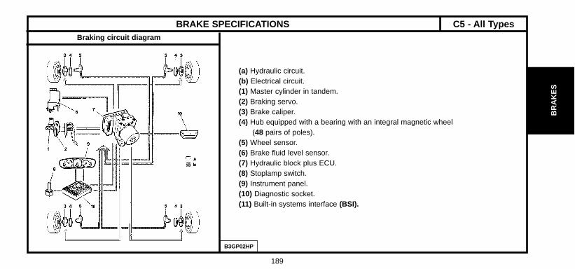
BR
AK
ES
189
BRAKE SPECIFICATIONSBraking circuit diagram
(a) Hydraulic circuit.(b) Electrical circuit.(1) Master cylinder in tandem.(2) Braking servo.(3) Brake caliper.(4) Hub equipped with a bearing with an integral magnetic wheel
(48 pairs of poles).(5) Wheel sensor.(6) Brake fluid level sensor.(7) Hydraulic block plus ECU.(8) Stoplamp switch.(9) Instrument panel.(10) Diagnostic socket.(11) Built-in systems interface (BSI).
B3GP02HP
C5 - All Types

BR
AK
ES
190
BRAKE SPECIFICATIONS
(7) Hydraulic block
Elements
Electronic ABS MK.60
47 way connectorECU.
7 ITT - AAlone on the hydraulic block.BASR MK.60
2 way black connector.
Front wheel The sensors are inductive-type.
5 ITT - A 96 332 952 80 Mounted on the pivot.sensor.Non-adjustable airgap: 0.2 to 1.5 mm.Tightening torque: 0.8 ± 0.2 m.daN
2 way black connector.
Rear wheel The sensors are inductive-type.
sensor.96 332 954 80 Mounted on the brake caliper support.
Non-adjustable airgap: 0.15 to 1.6 mm.Tightening torque: 0.8 ± 0.2 m.daN
Hub 4 SNR
Hub equipped with a bearing with an integral bearing. magnetic wheel (48 pairs of poles)
ABS MK.60
Hydraulic 96 371 711 80 Installed on the front LH wheelarch.
block.7 TEVES
BASK MK.60 4 adjustment channels.96 371 712 80
Ref. Supplier Part No. Observations
B3FP12XC
C5 - All Types

BR
AK
ES
191
BRAKE SPECIFICATIONS
Brake pedal carriage Front brake Rear brake
(15) Fixing on bodyshell 1.8 ± 0.25.(16) Servo fixing 2.1 ± 0.1.
(12) Caliper fixing on pivot 12± 1.8(13) Yoke fixing on caliper 3.1± 0.1 (14) Rear caliper fixing on suspension arm 7 ± 0.7
Tightening torques (m.daN).
B3FP130C B3FP12YC B3FP12ZC
C5 - All Types

BR
AK
ES
192
B3FP12JD
HANDBRAKE (Adjustment)
Adjustment
- Remove the rear ashtray from the handbrake console.- (1) Nut for adjusting the tension of the handbrake cables.- Raise and support the vehicle with the front wheels
hanging free.- Check the correct routing of the brake cables under the
vehicle.- Apply and release the handbrake 10 times .- Set the handbrake to the 5th notch .- Tighten the nut (1) until the front brakes are applied.- Pull the handbrake lever vigorously 4 to 5 times .- Set the handbrake to the 5th notch .- Check that the front brakes are applied.- With the handbrake released, check that the wheels
can be turned freely by hand.- Lower the vehicle.- Refit the rear ashtray to the handbrake console.
C5 - All Types

BR
AK
ES
193
B3FP139C B3FP13AC
BLEEDING AND FILLING THE BRAKING SYSTEM
Tools.
[1] Generic bleeding apparatus : "LURO" or similar.[2] PROXIA station : 4165-T.[3] LEXIA station : 4171-T.
Bleeding, filling.
Draining the brake fluid reservoir.- Drain the brake fluid reservoir (1) to the maximum (if necessary, use a clean syringe).- Disconnect the connector (3).- Uncouple the pipe (2).- Remove the reservoir (1) by separating the lugs «a» from the shaft (4).- Empty the brake fluid reservoir (1).- Clean the brake fluid reservoir (1).Remove : - The brake fluid reservoir (1).- The shaft (4).- Couple the pipe (2).- Reconnect the connector (3).
C5 - All Types

BR
AK
ES
194
B3FP13BC AB3FP13CC
BLEEDING AND FILLING THE BRAKING SYSTEM
Bleeding, filling (continued).Filling the braking system.
WARNING : Use only those hydraulic fluids that are approved and recommended.- Fill the brake fluid reservoir (1).
Bleeding the braking system.WARNING: During the bleeding operation, take care to maintain the level of brake fluid in the reser-voir and to top it up, using only brake fluid that is clean and clear.
Bleeding the primary circuit.WARNING: The ABS should not be active during the bleeding operation.- Front brake caliper: Bleed screw (5).- Rear brake caliper: Bleed screw (6).- Bleed each wheel cylinder, proceeding in the following order :
Front LH wheel.Front RH wheel.Rear LH wheel.Rear RH wheel.
C5 - All Types

BR
AK
ES
195
B3FP13DC
BLEEDING AND FILLING THE BRAKING SYSTEM
Bleeding, filling (continued).
With the bleeding apparatus- Connect the bleeding apparatus [1] on the brake fluid reservoir (1).- Adjust the apparatus pressure to 2 Bars .For each circuit : - Connect a transparent tube onto the bleed screw, submerge the other end of the tube in a clean container.- Open the bleed screw, wait until the fluid is flowing out without air bubbles.- Close the bleed screw.- Remove the bleeding apparatus [1] .- Check the brake fluid level (Should be between «DANGER» level and «MAXI» level).- Fill if necessary with the approved and recommended synthetic brake fluid.Without the bleeding apparatus.NOTE : Two operators are necessary.For each circuit :- Apply the brake pedal to place the circuit under pressure.- Connect a transparent tube onto the bleed screw, submerge the other end of the tube in a clean container.- Open the bleed screw, wait until the fluid is flowing out without air bubbles.- Close the bleed screw.- Remove the tool [1].NOTE : Recommence the process a second time if that is necessary.- Check the brake fluid level, (Should be between «DANGER» level and «MAXI» level).- Fill if necessary with the approved and recommended synthetic brake fluid.
C5 - All Types

BR
AK
ES
196
BLEEDING AND FILLING THE BRAKING SYSTEM
Bleeding, filling (continued).
Bleeding the secondary circuit.
NOTE : The bleeding apparatus is connected on the brake reservoir.- Use LEXIA or PROXIA diagnostic tools.
Select the menu corresponding to the vehicle :
- ABS menu.- ESP menu.
- Follow the instructions on the diagnostic tool.- At the end of the bleeding process, check and top up, if necessary, the brake fluid level.- Check that the brake pedal travel has not been lengthened, otherwise repeat the bleeding procedure.- Remove the tools.
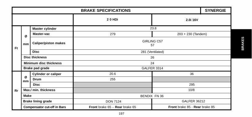
BR
AK
ES
197
BRAKE SPECIFICATIONS
2 0 HDi 2.0i 16V
23.8
279 203 + 230 (Tandem)
GIRLING C5757
281 (Ventilated)
26
24
GALFER 3314
20.6
255
295
10/8
BENDIX FN 36
DON 7124
Front brake 65 – Rear brake 65
36
GALFER 36212
Front brake 85 - Rear brake 85
Ft
Ø
mm
Master cylinder
Master-vac
Caliper/piston makes
Disc
Disc thickness
Minimum disc thickness
Brake pad grade
Rr
Ømm
Cylinder or caliper
Drum
Disc
Make
Max./ min. thickness
Brake lining grade
Compensator cut-off in Bars
SYNERGIE

BR
AK
ES
198
SYNERGIE BRAKES
- Set the vehicle at reference height (see page 180).
ESSENTIAL : Never alter the position of the upper nut (1).
- Refit the flanged nut (2).- Fit the tool 8204-T.
Drum
At shim A Yellow
RedAt shim B
Disc
Blue
- Adjust the nut (3) to allow the free passage, without play, of the red shim (B), withoutmoving the lever (4) downwards.
- Tighten the lock nut (5) without modifying the adjustment.- Remove the threaded rod at C. - Tighten the flanged nut (2) over the nut (3).
Manual adjustment of the compensator
B3FP10TC

BR
AK
ES
199
B3FP10UC
- Use the brake pressure checking equipment 4104-T, connect diagonally and bleed: Ø bleed screw : Caliper 8x125 - Wheel cylinder 7x100.- Set the vehicle at setting height.
- Pressure chart :
SYNERGIE BRAKES (continued)
DrumDisc
Engine : 2 0 HDi
Disc
Engine : 2.0i 16V
Front Rear Front Rear
40 40 50 50
65 65 85 85
135 86 135 100
- If the pressures are not correct, adjust as follows :- Refit the nut (1).- Adjust using the nut (2) to obtain the braking pressure.- Tighten the lock nut (3).- Hold the threaded rod (4).- Tighten the flanged nut (1) over the nut (2).
Checks and hydraulic adjustment of the compensator

BR
AK
ES
200
B3FP10WCB3FP10VC
HANDBRAKESYNERGIE
Slacken the cables using the nut (1).- Remove the blanking plug from hole A.- Position hole A opposite the toothed wheel (adjusting mechanism).- Turn the toothed wheel using a flat screwdriver until the disc locks.- LH side upwards.- RH side downwards.- Unlock the disc by turning in the opposite direction by 6 notches .
- Position the blade B of the blanking plug perpendicular to the linepassing through the centre of the disc and the centre of the hole.
- Tighten nut (1) to obtain a handbrake lever travel of 4 to 5 notches .- Tighten the lock nut (2).
B3FP10XC

201
HY
DR
AU
LIC
SY
ST
EM
B4CP01FP
HYDRAULIC SPECIFICATIONSLocation of components
(A) High pressure hydraulic circuit.(B) Low pressure hydraulic circuit.(C) Electric circuit.(21) Built-in Hydro-electronic Interface (BHI).(22) Front slimline sphere.(23) Front suspension cylinder.(24) Rear slimline sphere.(25) Rear suspension cylinder.(26) Front hydractive 3+ regulator accumulator.(27) Front hydractive 3+ regulator.(28) Rear hydractive 3+ regulator accumulator.(29) Rear hydractive 3+ regulator(30) Front height sensor.(31) Rear height sensor.(32) LDS fluid reservoir .(33) Suspension switch.
C5 - All Types

202
HY
DR
AU
LICS
YS
TE
M
B4BP01BC
HYDRAULIC SPECIFICATIONS
Reservoir
Function Component
"d" Induction(BHI) Built-in Hydro-electronic InterfacePower steering pump
"e" (BHI) Built-in Hydro-electronic Interface
"f" Return Power steering pump
"c" Suspension cylinders
Synthetic fluid TOTAL FLUIDE LDS .Capacity of the circuit 4.3 litres .
C5 - All Types
Reference

203
HY
DR
AU
LIC
SY
ST
EM
B3BP169P
HYDRAULIC SPECIFICATIONS
Built-in Hydro-electronic Interface (BHI).
Component Specifications
(36) Electric motor 2350 ± 150 rpm
Hydraulic unit comprising :Pump with 5 axial pistons Throughput = 0,7 l/min at 2300 rpm
(35) - Anti-pulse hydropneumatic Diameters of the pistons = 6,35 mmaccumulator Safety valve rating = 180 BarsA safety valve
(34) Electronic control unit
4 electrovalves: Front suspension inlet The vehicle’s anti-sink function is
(37) Rear suspension inlet assured by the exhaustFront suspension exhaust electrovalvesRear suspension exhaust
C5 - All Types
Reference

204
HY
DR
AU
LICS
YS
TE
M B4BP01CD B4DP003D
HYDRAULIC SPECIFICATIONSHydractive 3+ regulator
(40) Slimline sphere.
(39) Hydractive regulator.
(38) Electrovalve.
(41) Depressurisation screw.
Hydraulic unions
ReferenceTube diameter Tightening torque
(mm) m.daN
G 3,51,5 ± 0,3
H 6,35
J 10 2,5 ± 0,5
C5 - All Types

205
HY
DR
AU
LIC
SY
ST
EM
SPECIFICATION - IDENTIFICATION : SUSPENSION SPHERESSpecial features
Identification.
- Fitting of new slimline spheres with multilayer membranes, stone grey in colour.- It is forbidden to recharge or overhaul this type of sphere.- The number marked on the suspension sphere is the reference no. of the component and not the Part No.- The two-figure number marked on the suspension sphere indicates the initial inflation pressure value.
Example :
- The pressure value of this type of suspension sphere is given merely as a guide.- When checking, the value read could be higher than the nominal value.
NOTE : Suspension cylinders on the same axle should be equipped with the same type of membranes.
Tightening torques for these spheres : 2,7 ± 0,5 m.daN.
Suspension spheremarking
96 420 906 80 AG2 066 0 13h59 57
Batch of steel Day
of manufactureYear
of manufactureTime
of manufacturePressure rating
(Bars)
C5 - All Types

206
HY
DR
AU
LICS
YS
TE
M
B4BP01DD
SPECIFICATION - IDENTIFICATION : SUSPENSION SPHERES
(1) Front suspension sphere.
(2) Rear suspension sphere.
(3) Front hydractive 3+ regulator accumulator.
(4) Rear hydractive 3+ regulator accumulator.
C5 - All Types

207
SPECIFICATION - IDENTIFICATION : SUSPENSION SPHERESHydractive 3 suspension
Front suspension sphere (1)
WARNING : The number marked on the suspension sphere is the reference no. of the component and not the Part No.
Engines Suspension sphere marking Volume(cc) Pressure(Bars) Diameter of damper hole (mm)
6FZ 96 420 906 80 385 57 1.9/1.3
RHY-RHS-RHZ 96 420 907 80 1.75/1.3
Rear suspension sphere (2)
All types 96 420 905 80 385 31 0.7/0.48
Hydractive 3+ suspension
Front suspension sphere (1)
RFN-RLZ 96 420 908 80 385 44 0.9/0.48XFX-4HX 96 420 909 80 52
Rear suspension sphere (2)
All types 96 422 091 80 385 25 1.4/0.94
Hydractive regulator accumulator
Hydractive regulator Suspension sphere marking Volume (cc) Pressure (Bars)
Front (3) 96 420 898 80 385 62
Rear (4) 96 373 373 80 45
HY
DR
AU
LIC
SY
ST
EM

Petrol engines
208
H
ManualU 3 T
C
V 4 VC1.8i 16V
U 3H
AutomaticT
V 4C
VC
U 3H
T2.0HPi Manual
V 4C
VC
STARTER MOTORS
Vehicle Engine Gearbox Reference Class Climate
C5
CLIMATE : H (Hot), T (Temperate), C (Cold), VC (Very cold) - NOTE : See alternator references by class, table on page 212
C5
ELE
CT
RIC
AL
SY
ST
EM

ELE
CT
RIC
AL
SY
ST
EM
Petrol engines
STARTER MOTORS
Vehicle Engine Gearbox Reference Class Climate
C5
209
Manual
U 3H
T
V 4C
VC2.0i 16V
Automatic
U 3H
T
V 4C
VC
H
T2.0i 24S All Types R2 4
C
VC
CLIMATE : H (Hot), T (Temperate), C (Cold), VC (Very cold) - NOTE : See alternator references by class, table on page 212
C5

ELE
CT
RIC
AL
SY
ST
EM
210
Diesel engines
Y 5H
T
Z1 6C
VC
Y 5H
T
Z1 6
C
VC
H
T
Z3 6+C
VC
STARTER MOTORS
Vehicle Engine Gearbox Reference Class Climate
C5
CLIMATE : H (Hot), T (Temperate), C (Cold), VC (Very cold) - NOTE : See alternator references by class, table on page 212
2.0 HDi
(RHS-RHZ)
2.0 HDi
(RHY)
Manual
Automatic
C5
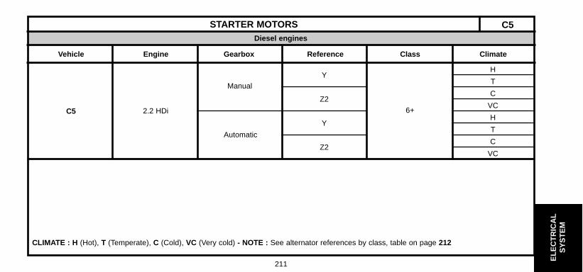
ELE
CT
RIC
AL
SY
ST
EM
211
Diesel engines
STARTER MOTORS
Vehicle Engine Gearbox Reference Class Climate
C5
YH
T
Z2C
VC
YH
T
Z2C
VC
CLIMATE : H (Hot), T (Temperate), C (Cold), VC (Very cold) - NOTE : See alternator references by class, table on page 212
C5
Automatic
Manual
2.2 HDi 6+

ELE
CT
RIC
AL
SY
ST
EM
212
Alternator reference
Make
VALEO MELCO BOSCH
STARTER MOTORS
Vehicle Engine Reference
Petrol
Diesel
1.8i 16V U D6 RA 72 M000T 82 081 EOAL 0983902.0i 16V
V M000T 85 3812.0 Hpi
3.0i 24S R2 D6 RA 661
X D6 RA 109 M001 T8 0381 A001 111 562F
Y D7 R 26 M001 T8 0481
Z1 D7 R 27
Z2 A001 236 080
Z3 D8 R 27
C5
C5
2.0 HDi2.2 HDi
Table of classes of starter motors
CLASS
Torque C
Maximum current for a speed of 1200 rpm
CLASS 2 CLASS 3 CLASS 4 CLASS 5 CLASS 6
5.5 Nm 6 Nm 10 Nm 11.5 Nm 11.5 Nm
I 275 A I 300 A I 430 A I 470 A I 500 A

ELE
CT
RIC
AL
SY
ST
EM
Diesel engines
213
Petrol engines
STARTER MOTORS
Vehicle Engine Gearbox Reference Class Climate
SYNERGIE
ManualU 3
HT
V 4C
VC
AutomaticU 3
HT
V 4C
VC
Y 5HT
Z1 6C
ManualVC
Y 5HT
Z1 6C
VC
CLIMATE : H (Hot), T (Temperate), C (Cold), VC (Very cold) - NOTE : See alternator references by class, table on page 214
SYNERGIE
2.0i 16V
2.0 Hdi2.0 16V HDi

ELE
CT
RIC
AL
SY
ST
EM
214
Alternator reference
Make
VALEO MELCO BOSCH
STARTER MOTORS
Vehicle Engine Reference
Petrol
Diesel
2.0I 16VU D6 RA 72 M000T8 2081 E0AL 098 390
V M000 T8 2081
2.0 HDi Y D7 R 26 M001 T8 5381
2.0 16V HDi Z1 D7 R 27
SYNERGIE
SYNERGIE
Table of classes of starter motors
CLASS
Torque C
Maximum current for a speed of 1200 rpm
CLASS 2 CLASS 3 CLASS 4 CLASS 5 CLASS 6
5.5 Nm 6 Nm 10 Nm 11.5 Nm 11.5 Nm
I 275 A I 300 A I 430 A I 470 A I 500 A

ELE
CT
RIC
AL
SY
ST
EM
215
Base With GPS Base With GPS Base With GPS Base With GPS12 12 H
12 12 TC
VCHTC
VCHTC
VCHTC
VC
ALTERNATORS C5
Climate
Class of alternatorWithout aircon
With Cold Pack Without Cold Pack With Cold PackWithout Cold Pack With aircon
99
99
99
9
9 99 9
12 12
9
12 1212 12
99
99
Vehicle Model Gearbox
Manual
Automatic
Automatic
Manual
1.8i 16V
2.0i 16V
C5
CLIMATE : H (Hot), T (Temperate), C (Cold), VC (Very cold) - NOTE : See alternator references by class, table on page 217
12 12
1212
9
12 12
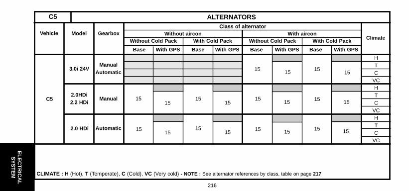
ELE
CT
RIC
AL
SY
ST
EM
216
Base With GPS Base With GPS Base With GPS Base With GPS
HTC
VCHTC
VCHTC
VC
ALTERNATORSC5
Climate
Class of alternatorWith airconWithout aircon
15
Vehicle Model Gearbox
ManualAutomatic
Manual
Automatic
2.0HDi2.2 HDi
3.0i 24V
2.0 HDi
C5
CLIMATE : H (Hot), T (Temperate), C (Cold), VC (Very cold) - NOTE : See alternator references by class, table on page 217
15
1515
15
1515
15
15
15
15 15
15
15
15 15
15
1515
15
With Cold Pack Without Cold Pack With Cold PackWithout Cold Pack

ELE
CT
RIC
AL
SY
ST
EM
217
ALTERNATORS C5Alternator reference
MakeVALEO
A 13 VI 204+ A002 TB 4891SG 10 B0 21
A003 TA 0891A14 VI 25+
SG 15 S0 16 A004 TF 0091 A 120 51 611SG 15 S0 21A14 VI 27+
SG 15 S0 18SG 15 S0 22A14 VI 41+
MELCO BOSCHVehicle Engine Gearbox Class
Alltypes
1.8i 16V2.0i 16V2.0 HPi
C5
(1) = With particle filter (FAP)
3.0i 24S12
9
152.0 HDi
2.0 HDi (1)2.2.HDi

ELE
CT
RIC
AL
SY
ST
EM
218
HTC
VCHTC
VCHTC
VC
ALTERNATORSSYNERGIE
ClimateClass of alternator
Without aircon
8
9
8 15
9
15
12
12
With airconVehicle Model Gearbox
Manual
Automatic
Manual
2.0i 16V
2.0 HDi2.0 HDi
16V
Synergie
CLIMATE : H (Hot), T (Temperate), C (Cold), VC (Very cold) - NOTE : See alternator references by class, table on page : 219

ELE
CT
RIC
AL
SY
ST
EM
219
ALTERNATORS SYNERGIEAlternator reference
MakeVALEO
A13 VI 2A6 A005 TA 6391SG 8 B0 21A13 VI 277+SG 10 B0 22
A003 TB 2691A14 VI 40+
SG 15 S0 17SG 15 S0 18SG 15 S0 22A14 VI 41+
MELCO BOSCHVehicle Model Gearbox Class
Alltypes
2.0i 16V
Synergie
9
12
8
152.0 HDi2.0 16V
HDi

ELE
CT
RIC
AL
SY
ST
EM
220
12 72 A 90 A
CHECKING THE ALTERNATOR OUTPUT
Connect as shown in the diagram opposite, using an ammeter (A), a voltmeter (V), and a rheostat (R) or a Volt/Ammeter/Rheostat com-bination.Referring to the vehicle’s equipment specification (see table opposite),adjust the engine speed and rheostat charge to obtain U=13.5V. Readthe voltage.
Reminder : The excitation energising current will flow through thewarning lamp; check that the warning lamp comes on when the igni-tion is switched on. It should go out when the engine has started(accelerate slightly).
CHECKING THE VOLTAGE REGULATOR
Set the rheostat to zero and disconnect all the electrical consumers.Display 5000 alternator rpm. If U alternator is > 14.7 V, the regulatoris faulty.Note : These tests should be performed with the engine hot and thebattery fully charged.
Speed
Class
2000rpm
3000rpm
4000rpm
5
7
8
9
29 A
42 A
49 A
62 A
39 A
54 A
62 A
76 A
43 A
59 A
68 A
83 A
100 A
15 99 A 128 A 140 A
Output under 13.5 VIntensity (A) / Alternator speed
CHARGING CIRCUIT - ALTERNATOR WITH MONO-FUNCTION REGULATORALL TYPES
D1AP01SC

ELE
CT
RIC
AL
SY
ST
EM
221
PRE-HEATING AND STARTING CIRCUITS
Vehicles Engines Pre-heater plugs Pre-heater control unitPre-post-heating
(Pre-heating time at 20°C)
C5
Synergie
2.0 HDI
2.0 16V HDI
2.2 HDI
CHAMPION CH 170CARTIER 51299011A
NAGARES 960411-P
BERU A0100 226 344CARTIER 51299011A
NAGARES 960411-P
Piloted by the dieselinjection ECU
Preheater plug resistance : 0.4 Ω ≤ R ≤ 0.6 Ω
C5 - SYNERGIE

AIR
CO
ND
ITIO
NIN
G
222
AIR CONDITIONING R 134 a (HFC)
Vehicle Engine version DateRefrigerant
refill(± 25 gr)
Compressor
Variable capacity Oil quantity cc Oil reference
(1) HARRISON Division.
1.8i 16V-2.0i 16V2.0 HPi
3.0i 24S 16V2.2 HDi
2.0 HPi
All Types
C5
SYNERGIE
11/2000 :650
+ 0 - 50 gr
SD 7 V16 SD 7 V16 SP 10
06/94 > 1000 ± 50 gr SD 7 V16 135 SP 10
DELPHI V5 (1) 265 ± 15 PLANETELF 488
C5 - SYNERGIE
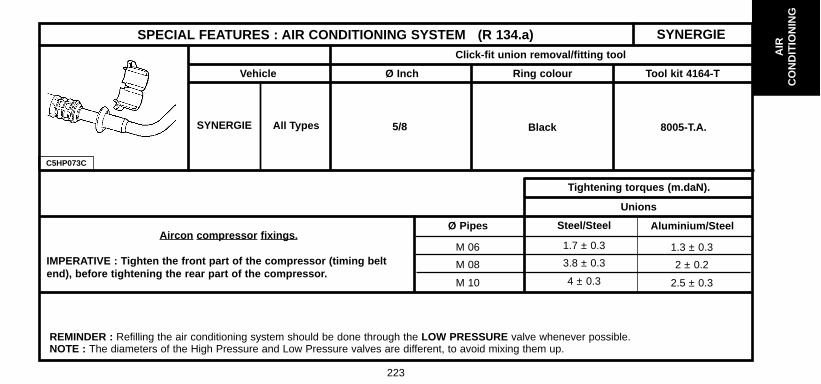
223
AIR
CO
ND
ITIO
NIN
G
SYNERGIE
C5HP073C
SPECIAL FEATURES : AIR CONDITIONING SYSTEM (R 134.a)Click-fit union removal/fitting tool
Ø InchVehicle
SYNERGIE All Types 5/8 Black 8005-T.A.
Ring colour Tool kit 4164-T
Tightening torques (m.daN).
Unions
Steel/Steel Aluminium/SteelØ Pipes
1.7 ± 0.3 1.3 ± 0.3M 06
3.8 ± 0.3 2 ± 0.2M 08
4 ± 0.3 2.5 ± 0.3M 10
REMINDER : Refilling the air conditioning system should be done through the LOW PRESSURE valve whenever possible.NOTE : The diameters of the High Pressure and Low Pressure valves are different, to avoid mixing them up.
Aircon compressor fixings.
IMPERATIVE : Tighten the front part of the compressor (timing beltend), before tightening the rear part of the compressor.

224
AIR
CO
ND
ITIO
NIN
G
Aircon all types YES
Without aircon NO
Base aircon NO
# 8148 Do not fit Water ingress
Automatic 8148 # 8421 YES (Behr) Body modification
aircon 8421 # YES if Exclusive 2 blowers
NO if X and SX 1 blower
SPECIAL FEATURES : AIR CONDITIONING SYSTEM (R 134.a)C5 - SYNERGIESummary table for presence of pollen filter
Vehicle Equipment RPO no. Presence of filter Observations
C5
SYNERGIE (*)
(*) = The (three) pollen filters on SYNERGIE are located at the base of the windscreen.

225
C5FP0C5C C5FP0C6D
SPECIAL FEATURES : AIR CONDITIONING SYSTEM (R 134.a)
Pollen filter
Remove :
- The trim (1) under the dashboard (driver’s side).
- The cover (2).
Unclip at « a » and pull out the pollen filter (3).
Remove the pollen filter (3).
C5
AIR
CO
ND
ITIO
NIN
G

226
SPECIAL FEATURES : AIR CONDITIONING SYSTEM (R 134.a)Drying cartridge
Tools
[1] Filling and recycling station MULLER - ECOTECHNICS[2] TORX adaptor 70 FACOM[3] After Sales kit (Bottle /skirt / bottle nozzle /grease / compressor oil)
Reminder : All repairs on an aircon circuit require the aircon circuit to be drained.
After carrying out the dismantling operations necessary to gain access to the condenser, proceed to cleanthe area of the skirt (8) of the reservoir (6) using a cloth, then replace the dryer reservoir (6).
Removing the plastic bracket holding the reservoir (6) : - Remove the screw (3) (Torx 20), from the bracket assembly/plastic counter-bracket (4) and (5).- Remove the counter-bracket (5).(Rotate it round the hinge in a clockwise direction).- Disengage the bracket from the harness (1) (Rotate it round the reservoir (6) anti-clockwise).- Remove the bracket (5) from the reservoir body (6).
Unscrewing the reservoir (6).
- Unscrew the reservoir (6) using the tool [2].
C5HP16EC
C5AIR
CO
ND
ITIO
NIN
G

227
C5HP16EC
SPECIAL FEATURES : AIR CONDITIONING SYSTEM (R 134.a)Condenser with integral reservoir (continued)
Removing the reservoir (6) from the base (8).
WARNING : This operation requires the greatest care, the base (8) should be kept clean prior to fittingthe new reservoir.- Remove the reservoir (6) and the protection skirt (7), avoiding WITHOUT FAIL any contact or collision
with other items under the bonnet (Risk of impurities entering the base (8)).- Check before refitting the reservoir (6) that the base (8) is clean.
(If it is not, clean in and around the base (8) with a paper cloth.)
Preparing the new dryer reservoir
- Remove the black plastic protection cap from the reservoir neck (6), leaving in place the greenprotection at the other end, in order to keep the new reservoir (6) sealed when mounting it in the base(8) of the condenser.
- Use the grease sachet in the replacement kit, to lubricate the threads of the reservoir.- Use the oil sachet in the replacement kit, to lubricate the two O-ring seals of the reservoir (6).- Position the reservoir (6), with its new protection skirt (7) from the replacement kit, and engage the
threads of the reservoir (6) in the base (8).- Check that the downward edge of the skirt (7), covers the base (8) all around it.
C5
AIR
CO
ND
ITIO
NIN
G

228
C5HP16EC
SPECIAL FEATURES : AIR CONDITIONING SYSTEM (R 134.a)Condenser with integral reservoir (continued)
WARNING : The reservoir (6) contains a drying agent. As soon as the black protection is removed, the reser-voir must be mounted in the base (8), otherwise there is a risk of damaging the air conditioning circuit.
Screwing the reservoir (6) into the base (8).
- Screw the reservoir (6) manually, until the neck of the reservoir (6) is in contact with the bottom of the base (8).
- Tighten with a torque spanner and tool [2] at (2) to 1.3 ± 0,1 m.daN.
Fitting the plastic bracket. (New, from the replacement parts kit).
Proceed in the opposite order to removal, tighten the screw (3) to 0.15 m.daN.
C5AIR
CO
ND
ITIO
NIN
G

229
ALL TYPESSPECIAL FEATURES : AIR CONDITIONING SYSTEM (R 134.a)Compressor lubricant.
ESSENTIAL: The compressor lubricant is extremely hygroscopic; always use FRESH oil.
Checking the compressor oil level.
There are three specific cases :- 1/ Repairs to a system without leaks.- 2/ Slow leak.- 3/ Fast leak.
1/ Repairing a system without leaks.a) - Using draining/recovery equipment not fitted with an oil decanter.- Drain the system as slowly as possible via the LOW PRESSURE valve, so as not to lose any oil.- No more oil should be added when filling the system with R 134.a fluid.b) - Using draining/filling equipment fitted with an oil decanter.- Drain the R 134.a fluid from the system in accordance with the instructions in the equipment handbook.- Measure the amount of oil recovered.- Add the same amount of NEW oil when filling the system with R 134.a fluid.c) - Replacing a compressor.- Remove the old compressor, drain it and measure the oil quantity.- Drain the new compressor (supplied full), so that the same amount of NEW oil is left in the compressor as was in the old compressor.- No more oil should be added when filling the system with R 134.a fluid.
AIR
CO
ND
ITIO
NIN
G

230
SPECIAL FEATURES : AIR CONDITIONING SYSTEM (R 134.a)ALL TYPES
Checking the compressor oil level (continued)
2) Slow leak.
- Slow leaks do not lead to oil loss, therefore the same procedure should be followed as if there was no leak at all.
3/ Fast leak.
This type of leak causes both oil loss as well as allowing air to enter the system.
It is therefore necessary to :
- Replace the dryer.- Drain as much oil as possible (when replacing the faulty component).
Either before or during filling of the system with R 134.a fluid, introduce 80 cc of NEW oil into the system.
AIR
CO
ND
ITIO
NIN
G

231
CHECKING THE EFFICIENCY OF THE AIR CONDITIONING SYSTEM
CHECKING TEMPERATURES.
ALL TYPES
TOOLS
Two thermometers.
Preliminary conditions.
Position of the air conditioning controls :- Maximum cold air.- Air blower in maximum position.- Air distributor in "ventilation" position, with the dashboard vents open.- Air intake flap in "exterior air" position.
Conditions and vehicle equipment.
- Bonnet closed.- Doors and windows shut.- Ensure the vehicle is in a sheltered area (away from wind, sun, etc..).
CHECKS.
If all these conditions are met, take the following action :
- Start the engine, with the air conditioning off, and wait for the coolingfan first speed to cut in.
- Operate the air conditioning and set the engine speed to 2500 rpm .
NOTE : If the exterior temperature reaches 40 °C, the engine speed willreturn to 2000 rpm in order to prevent the compressor from being cut offby the High Pressure safety device (Pressostat).
After the air conditioning has been on for three minutes, measure :- the exterior temperature in the workshop,- the temperature of the air coming out of the central vents.
Compare the two values using the table overleaf.
AIR
CO
ND
ITIO
NIN
G

232
CHECKING THE EFFICIENCY OF THE AIR CONDITIONING SYSTEMSYNERGIE
CHECKING TEMPERATURES. (continued)
Vehicle using R134.a fluid (Compressor with variable capacity)
Exterior temperature in °C
Temperature in °Cat the central vents
Vehicles
SYNERGIE 12 ± 3 8 ± 3
40 35 30 25 20 15
(*) At exterior temperature 20°C, air temperature from the central vents is for second speed of the ventilator fan.If fan operates at first speed, then air temperature from the central vents becomes 8.4 ± 3 °C.NOTE : In general, the temperature of the air being blown from the central vents should be around 5°C to 8°C.
AIR
CO
ND
ITIO
NIN
G

233
CHECKING THE EFFICIENCY OF THE AIR CONDITIONING SYSTEM ALL TYPES
CHECKING PRESSURES
TOOLS : 1 Charging station and 2 Thermometers.Observing the preliminary conditions, as well as vehicle equipment and checks (see page 231) :After the air conditioning has been operating for three minutes, record the following parameters :
- The temperature of the air coming out of the central vents(See the table on page 288).
- The High Pressure.- The Low Pressure.Compare the values recorded with the table below, or the graphs.
Exterior temperature in °C 40 35 30 25 20 15
Vehicles
SYNERGIEHigh pressure (Bars)
Low pressure (Bars)16 ± 3 13 ± 3
2.1 ± 0.3 1.8 ± 0.3
Vehicle using R134.a fluid (Compressor with variable capacity)
AIR
CO
ND
ITIO
NIN
G

234
C5HP15QP
AIR CONDITIONING SYSTEM R 134.aEngines : 6FZ - RFN - RLZ
(1) High pressure valve.
(2) Low pressure valve.
(3) Pressostat.
(4) Capacity.
(a) Condenser bracket Tighten to 0,8 m.daN
(b) Pressure control valveTighten to 0,8 m.daN
(c) Compressor bracketTighten to 2,5 ± 0,1 m.daN
(d) Condenser dryer reservoir Tighten to 1,4 ± 0,2 m.daN.
C5AIR
CO
ND
ITIO
NIN
G

235
C5HP15RP
AIR CONDITIONING SYSTEM R 134.aEngine : XFX
(1) High pressure valve.
(2) Low pressure valve.
(3) Pressostat.
(4) Capacity.
(a) Condenser bracket Tighten to 0,8 m.daN
(b) Pressure control valveTighten to 0,8 m.daN
(c) Compressor bracketTighten to 2,5 ± 0,1 m.daN
(d) Condenser dryer reservoir Tighten to 1,4 ± 0,2 m.daN.
C5
AIR
CO
ND
ITIO
NIN
G

236
C5HP15SP
AIR CONDITIONING SYSTEM R 134.aEngines : RHY - RHZ
(1) High pressure valve.
(2) Low pressure valve.
(3) Pressostat.
(4) Capacity.
(a) Condenser bracket Tighten to 0,8 m.daN
(b) Pressure control valveTighten to 0,8 m.daN
(c) Compressor bracketTighten to 2,5 ± 0,1 m.daN
(d) Condenser dryer reservoir Tighten to 1,4 ± 0,2 m.daN.
C5AIR
CO
ND
ITIO
NIN
G
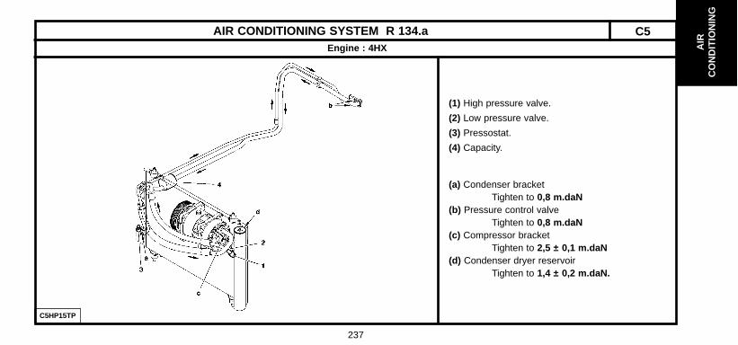
237
C5HP15TP
AIR CONDITIONING SYSTEM R 134.aEngine : 4HX
(1) High pressure valve.
(2) Low pressure valve.
(3) Pressostat.
(4) Capacity.
(a) Condenser bracket Tighten to 0,8 m.daN
(b) Pressure control valveTighten to 0,8 m.daN
(c) Compressor bracketTighten to 2,5 ± 0,1 m.daN
(d) Condenser dryer reservoir Tighten to 1,4 ± 0,2 m.daN.
C5
AIR
CO
ND
ITIO
NIN
G

238
AIR CONDITIONING SYSTEM R 134.aSYNERGIE - XU - EW10
C5HP15PP
Tightening torques.
(1) High pressure valve(2) Low pressure valve (3) Pressostat, tighten to 1,8 m.daN(4) Dryer(5) Clickfit union.
a) 0,8 m.daNb) 4 m.daNc) 0,8 m.daN
C5HP12EC
AIR
CO
ND
ITIO
NIN
G

239
AIR CONDITIONING SYSTEM R 134.a SYNERGIE - DW10
C5HP15EP
Tightening torques.
(1) High pressure valve(2) Low pressure valve (3) Clickfit union.(4) Pressostat, tighten to 1,8 m.daN(5) Flange fixing, tighten to 0,8 m.daN.(6) Flange fixing, tighten to 0,8 m.daN.(7) Flange fixing, tighten to 4 m.daN.
C5HP12EC
AIR
CO
ND
ITIO
NIN
G