prisma plus operation manual eng€¦ · indicated under , , and . the definition of each hazard is...
TRANSCRIPT

Operating Manual

Introduction
The automated slide stainer "Tissue-Tek Prisma®Plus (hereinafter referred to as the "instrument")" is an instrument that automatically stains paraffin strips, frozen strips, cells and other tissues pasted on slides. Read this Operating Manual carefully so that you can fully utilize the performance of the instrument based on correct procedures. Since the instrument uses organic solvents, exercise due caution when operating the instrument.
Manufactured for: Sakura Finetek U.S.A., Inc. Torrance, CA 90501 Sakura Finetek Europe B.V., 2048 Alphenaanden Rijn. NL Sakura Finetek Japan Co., Ltd. Tokyo, Japan 103-0023
Manufactured by: Sakura Seiki Co., Ltd. Nagano, Japan
(a)
Table of Contents
Safety Precautions ................................................................................................................................... (e)
Explanation of Terms................................................................................................................................ (p)
Chapter 1 Basics of the System
Installation Method .................................................................................................................................. 1-1
Installing the Instrument ...................................................................................................................... 1-1
Flow of Installation ........................................................................................................................... 1-1
Required Tools ................................................................................................................................. 1-1
Installation Environment .................................................................................................................. 1-1
Checking the Installation Condition ..................................................................................................... 1-2
Cecking the Work Area ........................................................................................................................ 1-3
Transportation ..................................................................................................................................... 1-3
Unpacking Procedure .......................................................................................................................... 1-4
Unpacking the System ..................................................................................................................... 1-4
Removing the Securing Members Inside the Instrument ................................................................ 1-6
Switching the Power-supply Voltage Setting ....................................................................................... 1-7
Checking the Accessories ................................................................................................................... 1-7
Checking the Installation (Securing the Instrument) ........................................................................... 1-9
Installing the parts around the instrument ........................................................................................... 1-9
Installation of Accessories ................................................................................................................. 1-14
Turning on the Power ........................................................................................................................ 1-16
Specification .......................................................................................................................................... 1-17
Name of Each Part ................................................................................................................................ 1-19
Standard Accessories/Options .............................................................................................................. 1-21
Basics .................................................................................................................................................... 1-23
Basics on This Instrument ................................................................................................................. 1-23
Instrument Overview ...................................................................................................................... 1-23
Stain Process Modes ..................................................................................................................... 1-23
User Management by Password ................................................................................................... 1-23
Logon/Logoff Function ................................................................................................................... 1-24
Safety Mechanism of the Instrument ............................................................................................. 1-24
How to Open and Close the Hood/Door ........................................................................................ 1-24
Handling the Touch-panel Display ................................................................................................. 1-25
Various Gateways .......................................................................................................................... 1-26
Relationship of Solution Configurations and Station Numbers ...................................................... 1-28
Explanation of Menu Screens ............................................................................................................... 1-31
Stain Menu ........................................................................................................................................ 1-31
Explanation of Icons in the Stain Process Menu Tab .................................................................... 1-32
Utility Menu Tab ................................................................................................................................. 1-33
Explanation of Icons in the Utility Menu tab ................................................................................... 1-33

(b)
Edit Menu Tab .................................................................................................................................... 1-34
Explanation of Icons in the Edit Menu Tab .................................................................................... 1-34
System Setup ........................................................................................................................................ 1-35
System Setup .................................................................................................................................... 1-35
Setting Date and Time ....................................................................................................................... 1-37
Entering Year ................................................................................................................................. 1-37
Entering Month .............................................................................................................................. 1-37
Entering Day .................................................................................................................................. 1-37
Entering Hours and Minutes .......................................................................................................... 1-37
am/pm ............................................................................................................................................ 1-37
Setting User IDs, Passwords and Accessible Functions ................................................................... 1-38
Setting an ID .................................................................................................................................. 1-38
Setting a Password ........................................................................................................................ 1-38
Setting Accessible Functions ......................................................................................................... 1-39
Stain Process ................................................................................................................................. 1-39
Utility .............................................................................................................................................. 1-39
Edit ................................................................................................................................................. 1-39
Fume Filter Management .................................................................................................................. 1-40
Whether or Not to Use Fume Filter Management.......................................................................... 1-40
Setting a Time Limit ....................................................................................................................... 1-40
Resetting the Actual Time .............................................................................................................. 1-40
Adjusting the Water Flow................................................................................................................... 1-41
Export Data ........................................................................................................................................... 1-42
Names of Files Exported to a CF Card .......................................................................................... 1-43
Chapter 2 Operating Procedure
Operating Procedure ............................................................................................................................... 2-1
Flow of Stain Process Operation ......................................................................................................... 2-1
Flow of Stain Process Operation ..................................................................................................... 2-1
Preparation for Stain Process ............................................................................................................. 2-2
Opening the Water Supply ............................................................................................................... 2-2
Logging On to the Instrument .......................................................................................................... 2-2
Selecting and Saving a Solution Configuration and Setting Solutions ................................................ 2-3
Setting Slides into Baskets .................................................................................................................. 2-4
Start of Stain Process .......................................................................................................................... 2-5
Operations Permitted during Stain Process ........................................................................................ 2-7
Adding a Basket ............................................................................................................................... 2-7
Setting Priority Start ......................................................................................................................... 2-8
Checking the End Station Status ..................................................................................................... 2-8
Checking the Staining Status .............................................................................................................. 2-9
Menu Operations Permitted during Staining Process ................................................................... 2-10
Pausing and Aborting Stain Process ............................................................................................. 2-11
Removing a Basket during Stain Process ..................................................................................... 2-12
End of Stain Process ......................................................................................................................... 2-12
(c)
Removing Stained Baskets............................................................................................................ 2-12
End of Operation ............................................................................................................................... 2-12
How to Start Stain Process by Specifying the Start and End Steps ................................................. 2-13
Setting a Solution Configuration ........................................................................................................... 2-15
Creating a New Solution Configuration ............................................................................................. 2-15
Saving a Staining Program Name ................................................................................................. 2-15
Setting Up a Solution Configuration .............................................................................................. 2-16
Setting an Edit Solution Configuration ........................................................................................... 2-17
Mix Parameter Setup ..................................................................................................................... 2-20
Enhanced Wash Parameter Setup ................................................................................................ 2-20
Basket Lifting Speed and Water Wash Cycle Time Parameter Setup ........................................... 2-21
Temperature Settings ..................................................................................................................... 2-21
Editing a Solution Configuration ........................................................................................................ 2-22
Copying a Solution Configuration ...................................................................................................... 2-22
Editing a Solution Name .................................................................................................................... 2-23
Creating and Editing a Solution Name .......................................................................................... 2-23
Copying a Solution Name .............................................................................................................. 2-24
Setting a Staining Program ................................................................................................................... 2-25
Creating a New Staining Program ..................................................................................................... 2-25
Saving a Staining Program Name ................................................................................................. 2-25
Creating a Staining Program ......................................................................................................... 2-26
Editing a Staining Program ................................................................................................................ 2-31
Copying a Staining Program ............................................................................................................. 2-32
Checking a Staining Program............................................................................................................ 2-33
How to Use the Bar Code Reader, and It's Function (Options) ............................................................ 2-34
Overview ............................................................................................................................................ 2-34
Applicable Solutions .......................................................................................................................... 2-34
How to Use Sakura Staining Solutions ............................................................................................. 2-34
Editing a Solution Configuration .................................................................................................... 2-34
How to Enter Sakura Solution Bar Code Data............................................................................... 2-35
How to Use Sakura Staining Kit ........................................................................................................ 2-36
Editing a Solution Configuration .................................................................................................... 2-36
How to Enter Kit Component Solution Bar Code Data .................................................................. 2-37
Resetting the Solution Usage Information ......................................................................................... 2-39
Outputting Process Report ................................................................................................................ 2-40
Solution Usage Information Report ............................................................................................... 2-40
Process Report .............................................................................................................................. 2-41
Solution Configuration Report........................................................................................................ 2-42
Barcode History Report ................................................................................................................. 2-43
Deleting a Solution Configuration/Staining Program/Solution Name/Process Report ...................... 2-44
Deleting a Solution Configuration .................................................................................................. 2-44
Deleting a Staining Program .......................................................................................................... 2-45
Deleting a Solution Name .............................................................................................................. 2-45
Deleting a Process Report ............................................................................................................. 2-45
(d)
Action to Be Taken upon Power Outage ............................................................................................... 2-46
Power Recovery Operation ............................................................................................................... 2-46
Action to Be Taken upon Error .............................................................................................................. 2-47
Error Handling ................................................................................................................................... 2-47
Errors with a Number ..................................................................................................................... 2-47
Other Errors ................................................................................................................................... 2-47
Chapter 3 Maintenance and Inspection
Daily Inspection and Cleaning ................................................................................................................ 3-1
Inspection and Cleaning Methods ....................................................................................................... 3-1
Cleaning the Solution Reservoirs and Baskets ............................................................................... 3-1
Cleaning the Drying Stations ........................................................................................................... 3-1
Cleaning the Heating Stations ......................................................................................................... 3-1
Replacing Activated Carbon Filters ................................................................................................. 3-2
Cleaning the Arm Holder and Basket Adapter ................................................................................. 3-2
Cleaning the Water Supply Strainer ................................................................................................ 3-3
Cleaning the Cabinet ....................................................................................................................... 3-3
Cleaning the Wash Station Nozzle .................................................................................................. 3-4
Cleaning the Drain Hose .................................................................................................................. 3-4
Chapter 4 Troubleshooting
Troubleshooting ...................................................................................................................................... 4-1
Error Codes Displayed during System Operation ............................................................................... 4-1
Instrument Conditions and Recovery Actions ..................................................................................... 4-7
(e)
Safety Precautions
Designation of "Instrument Control Manager" ● Operation of the instrument requires expert knowledge of the target application, method of use, and so
on. So that the instrument can be used correctly and safely, designate a "Instrument Control Manager." ● When the instrument is delivered, the Instrument Control Manager should receive explanation on the
handling of the instrument directly from our sales representative. * Before using the instrument, read "Safety Precautions" to ensure the correct use of the instrument. * The cautionary instructions provided herein are intended to ensure that the instrument will be used safely
in a manner preventing operator from injury and property damage. * In this manual, instructions pertaining to different levels of potential hazards are classified as and
indicated under , , and .
The definition of each hazard is defined below. pertains to a potential hazard where failure to observe the specified instruction may result in death or
serious injury of the operator or other person.
pertains to a potential hazard where failure to observe the specified instruction may result in a serious
injury of the operator or other person.
pertains to a potential hazard where failure to observe the specified instruction may result in damage to
this instrument or other property, or affect the process results.
pertains to an item to pay attention to or other useful information.
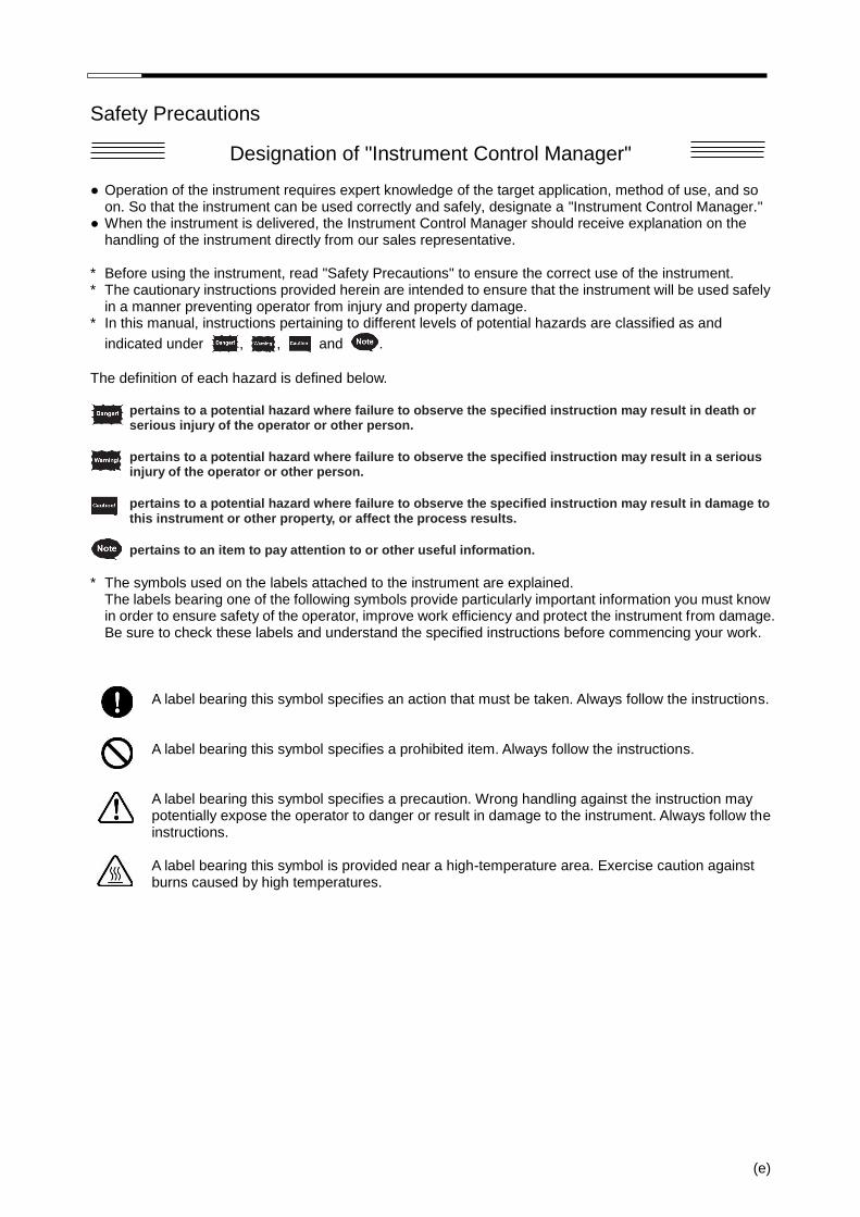
* The symbols used on the labels attached to the instrument are explained.
The labels bearing one of the following symbols provide particularly important information you must know in order to ensure safety of the operator, improve work efficiency and protect the instrument from damage. Be sure to check these labels and understand the specified instructions before commencing your work.
A label bearing this symbol specifies an action that must be taken. Always follow the instructions. A label bearing this symbol specifies a prohibited item. Always follow the instructions. A label bearing this symbol specifies a precaution. Wrong handling against the instruction may potentially expose the operator to danger or result in damage to the instrument. Always follow the instructions. A label bearing this symbol is provided near a high-temperature area. Exercise caution against burns caused by high temperatures.
Safety Precautions
(f)
WARNING
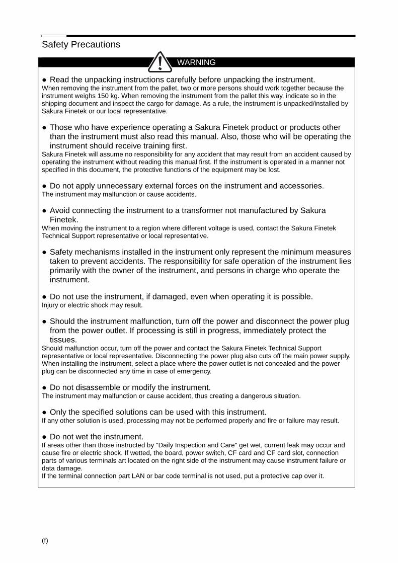
● Read the unpacking instructions carefully before unpacking the instrument. When removing the instrument from the pallet, two or more persons should work together because the instrument weighs 150 kg. When removing the instrument from the pallet this way, indicate so in the shipping document and inspect the cargo for damage. As a rule, the instrument is unpacked/installed by Sakura Finetek or our local representative.
● Those who have experience operating a Sakura Finetek product or products other than the instrument must also read this manual. Also, those who will be operating the instrument should receive training first.
Sakura Finetek will assume no responsibility for any accident that may result from an accident caused by operating the instrument without reading this manual first. If the instrument is operated in a manner not specified in this document, the protective functions of the equipment may be lost.
● Do not apply unnecessary external forces on the instrument and accessories. The instrument may malfunction or cause accidents.
● Avoid connecting the instrument to a transformer not manufactured by Sakura Finetek.
When moving the instrument to a region where different voltage is used, contact the Sakura Finetek Technical Support representative or local representative.
● Safety mechanisms installed in the instrument only represent the minimum measures taken to prevent accidents. The responsibility for safe operation of the instrument lies primarily with the owner of the instrument, and persons in charge who operate the instrument.
● Do not use the instrument, if damaged, even when operating it is possible. Injury or electric shock may result.
● Should the instrument malfunction, turn off the power and disconnect the power plug from the power outlet. If processing is still in progress, immediately protect the tissues.
Should malfunction occur, turn off the power and contact the Sakura Finetek Technical Support representative or local representative. Disconnecting the power plug also cuts off the main power supply. When installing the instrument, select a place where the power outlet is not concealed and the power plug can be disconnected any time in case of emergency.
● Do not disassemble or modify the instrument. The instrument may malfunction or cause accident, thus creating a dangerous situation.
● Only the specified solutions can be used with this instrument. If any other solution is used, processing may not be performed properly and fire or failure may result.
● Do not wet the instrument. If areas other than those instructed by "Daily Inspection and Care" get wet, current leak may occur and cause fire or electric shock. If wetted, the board, power switch, CF card and CF card slot, connection parts of various terminals art located on the right side of the instrument may cause instrument failure or data damage. If the terminal connection part LAN or bar code terminal is not used, put a protective cap over it.
Safety Precautions
(g)
WARNING
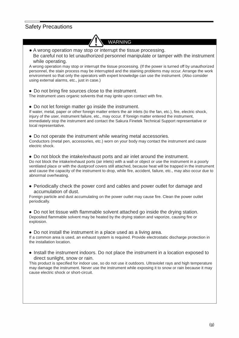
● A wrong operation may stop or interrupt the tissue processing. Be careful not to let unauthorized personnel manipulate or tamper with the instrument while operating.
A wrong operation may stop or interrupt the tissue processing. (If the power is turned off by unauthorized personnel, the stain process may be interrupted and the staining problems may occur. Arrange the work environment so that only the operators with expert knowledge can use the instrument. (Also consider using external alarms, etc., just in case.)
● Do not bring fire sources close to the instrument. The instrument uses organic solvents that may ignite upon contact with fire.
● Do not let foreign matter go inside the instrument. If water, metal, paper or other foreign matter enters the air inlets (to the fan, etc.), fire, electric shock, injury of the user, instrument failure, etc., may occur. If foreign matter entered the instrument, immediately stop the instrument and contact the Sakura Finetek Technical Support representative or local representative.
● Do not operate the instrument while wearing metal accessories. Conductors (metal pen, accessories, etc.) worn on your body may contact the instrument and cause electric shock.
● Do not block the intake/exhaust ports and air inlet around the instrument. Do not block the intake/exhaust ports (air inlets) with a wall or object or use the instrument in a poorly ventilated place or with the dustproof covers still attached, because heat will be trapped in the instrument and cause the capacity of the instrument to drop, while fire, accident, failure, etc., may also occur due to abnormal overheating.
● Periodically check the power cord and cables and power outlet for damage and
accumulation of dust. Foreign particle and dust accumulating on the power outlet may cause fire. Clean the power outlet periodically.
● Do not let tissue with flammable solvent attached go inside the drying station. Deposited flammable solvent may be heated by the drying station and vaporize, causing fire or explosion.
● Do not install the instrument in a place used as a living area. If a common area is used, an exhaust system is required. Provide electrostatic discharge protection in the installation location.
● Install the instrument indoors. Do not place the instrument in a location exposed to
direct sunlight, snow or rain. This product is specified for indoor use, so do not use it outdoors. Ultraviolet rays and high temperature may damage the instrument. Never use the instrument while exposing it to snow or rain because it may cause electric shock or short-circuit.
Safety Precautions
(h)
WARNING
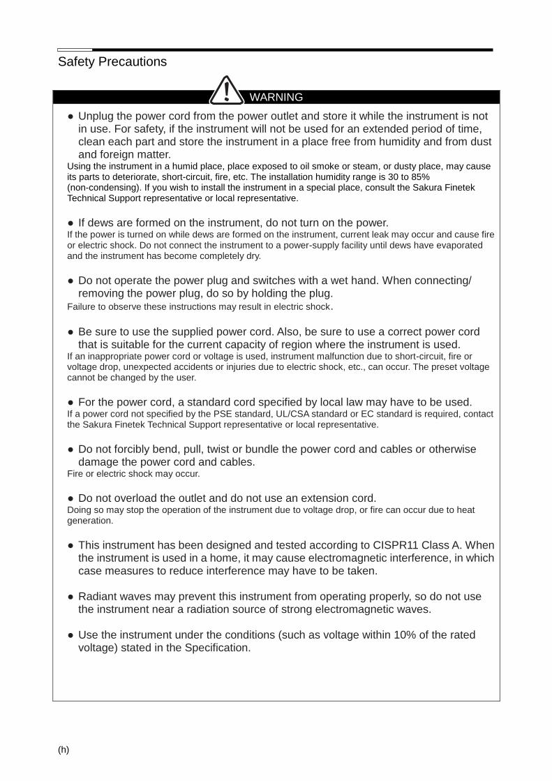
● Unplug the power cord from the power outlet and store it while the instrument is not in use. For safety, if the instrument will not be used for an extended period of time, clean each part and store the instrument in a place free from humidity and from dust and foreign matter.
Using the instrument in a humid place, place exposed to oil smoke or steam, or dusty place, may cause its parts to deteriorate, short-circuit, fire, etc. The installation humidity range is 30 to 85% (non-condensing). If you wish to install the instrument in a special place, consult the Sakura Finetek Technical Support representative or local representative.
● If dews are formed on the instrument, do not turn on the power. If the power is turned on while dews are formed on the instrument, current leak may occur and cause fire or electric shock. Do not connect the instrument to a power-supply facility until dews have evaporated and the instrument has become completely dry.
● Do not operate the power plug and switches with a wet hand. When connecting/
removing the power plug, do so by holding the plug. Failure to observe these instructions may result in electric shock. ● Be sure to use the supplied power cord. Also, be sure to use a correct power cord
that is suitable for the current capacity of region where the instrument is used. If an inappropriate power cord or voltage is used, instrument malfunction due to short-circuit, fire or voltage drop, unexpected accidents or injuries due to electric shock, etc., can occur. The preset voltage cannot be changed by the user.
● For the power cord, a standard cord specified by local law may have to be used. If a power cord not specified by the PSE standard, UL/CSA standard or EC standard is required, contact the Sakura Finetek Technical Support representative or local representative.
● Do not forcibly bend, pull, twist or bundle the power cord and cables or otherwise
damage the power cord and cables. Fire or electric shock may occur.
● Do not overload the outlet and do not use an extension cord. Doing so may stop the operation of the instrument due to voltage drop, or fire can occur due to heat generation.
● This instrument has been designed and tested according to CISPR11 Class A. When
the instrument is used in a home, it may cause electromagnetic interference, in which case measures to reduce interference may have to be taken.
● Radiant waves may prevent this instrument from operating properly, so do not use
the instrument near a radiation source of strong electromagnetic waves. ● Use the instrument under the conditions (such as voltage within 10% of the rated
voltage) stated in the Specification.

Safety Precautions
(i)
CAUTION
● Do not pinch the drain hose or allow it to slacken. Water will not be drained properly and overflow from the instrument.
● Set the solution station (tray) in the correct location. If not, the tissues may not be soaked in the solution and staining problems may occur.
● Store the slides evenly in the basket. If the slides are stored unevenly, basket movements are affected during the staining operation.
● Before staining is started, confirm that the end station has been set. If the end station is not set, the basket cannot be put down and will remain gripped. If the next basket is processed in this condition, the baskets may collide with each other and the tissues may be damaged.
● Do not touch the moving arm. The arm should stop automatically when the hood is opened, but it may continue to operate if a series of operations is still ongoing. Touching the moving arm may result in injury. If you must move the arm by hand, confirm that the arm has stopped completely and then move the arm with due caution by following the onscreen messages on the display.
● Do not open the hood or door unless necessary. Open the hood or door only when required by the operations explained in this manual. If the hood or door remains open for a long period of time, organic gas may be released from the instrument. Also, opening the hood or door during staining stops the arm, which may cause the tissues to dry up or extend the staining time and eventually affect the stained quality of tissues.
● Be careful not to pinch your hand when opening/closing the hood or door. Be careful not to pinch your hand between the fixed part and moving part of the hood or door or between the hood and door.
● Do not move the instrument while operating. Move the instrument after removing all
solution bottles, paraffin containers and other components carrying liquid inside. Moving the instrument while operating may cause the solution or paraffin to leak. Accident or failure may
also occur. ● If the straining process is suspended, the process may be negatively affected
depending on the situation. Remember to resume operation. Prolonged suspension may negatively affect the stain process. Keep the suspension time to the minimum.
● When the expiration date of the current solution is passed, a message appears to
urge exchanging the solution. Exchange the solution properly in order to maintain the staining quality.
● The safety data sheet of each solution used can be obtained from the
supplier/manufacturer of the solution. You can also download it from the website of respective supplier/manufacturer of the solution.
● Do not insert a metal bar or other metal object into the hot air outlet of any drying
station or use a metal product to reset an over temperature protector. Metal contact may cause electric shock.

Safety Precautions
(j)
CAUTION
● Do not allow any foreign object to be caught between the hood/door and the stainer. It may cause an unexpected problem.
● Use tap water for the water supply. Use of water containing pollutants may result in staining problems.
● Confirm that no paper or foreign object is present at the hood or outlet of any drying
station. It may result in insufficient drying.
● Do not touch the drying stations and heating stations while the instrument is
operating. These stations become very hot during operation, so touching them may result in burns.
● Securely connect the water supply hose and drain hose to make sure water will not
leak. If water leaks, the facility may be damaged.
● Before using the instrument, inspect the water supply hose and drain hose to ensure
that they are free from damage and connected properly. It may cause an unexpected problem.
● Close the water tap after using the instrument. If the water tap remains open, the water supply hose may accidentally come off due to water pressure and cause water leaks.
● Clean the water supply strainer regularly. Also, close the supply source water tap
before cleaning. If the water supply strainer is not cleaned regularly, the water supply volume will drop and washing problems may occur. Check the flow rate after cleaning. If the water supply strainer is cleaned with the supply source tap open, water will overflow when the strainer is removed.
● Clean the drying station regularly. If the drying solution is not cleaned regularly, paraffin will accumulate in the pan and cause the temperature to vary, resulting in staining problems.
● Clean the water supply nozzle regularly. If the water supply nozzle is not cleaned regularly, contaminants may attach to the nozzle and enter the tissues, causing staining problems.
● Clean the instrument thoroughly after using corrosive solutions. Some solutions have corrosivity and other aggressive properties that damage the instrument. It is best to avoid using these corrosive solutions, but if you must use a corrosive solution, remove the solution from the instrument and store it properly after use and also clean the instrument thoroughly. If this is not performed, the metal parts will corrode (rust, etc.). [Corrosive Solutions] Acids [hydrochloric acid (HCl), hydrobromic acid (HBr), hydrofluoric acid (HF), etc.], staining solutions and reagent solutions containing hydrochloric acid (Schiff’s reagent, cold Schiff, sulfurous acid solution, resorcin‐fuchsin staining solution, etc.), oxidizing chlorides [ferric chloride (FeCl3), mercuric chloride (HgCl2), cupric chloride (CuCl2), sodium hypochloride (NaOCl), etc.], tioculfates [sodium tiosulfate (Na2S2O3), etc.], organic acids [formic acid (HCOOH), acetic acid (CH3COOH), bromic acid (C204H2), lactic acid (CH3CH(OH)COOH), etc.]
Safety Precautions
(k)
CAUTION
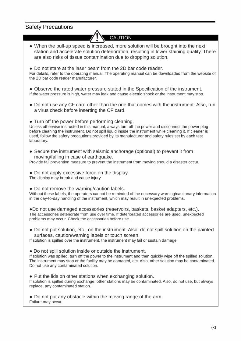
● When the pull-up speed is increased, more solution will be brought into the next station and accelerate solution deterioration, resulting in lower staining quality. There are also risks of tissue contamination due to dropping solution.
● Do not stare at the laser beam from the 2D bar code reader. For details, refer to the operating manual. The operating manual can be downloaded from the website of the 2D bar code reader manufacturer.
● Observe the rated water pressure stated in the Specification of the instrument. If the water pressure is high, water may leak and cause electric shock or the instrument may stop.
● Do not use any CF card other than the one that comes with the instrument. Also, run
a virus check before inserting the CF card. ● Turn off the power before performing cleaning. Unless otherwise instructed in this manual, always turn off the power and disconnect the power plug before cleaning the instrument. Do not spill liquid inside the instrument while cleaning it. If cleaner is used, follow the safety precautions provided by its manufacturer and safety rules set by each test laboratory.
● Secure the instrument with seismic anchorage (optional) to prevent it from
moving/falling in case of earthquake. Provide fall prevention measure to prevent the instrument from moving should a disaster occur.
● Do not apply excessive force on the display. The display may break and cause injury.
● Do not remove the warning/caution labels. Without these labels, the operators cannot be reminded of the necessary warning/cautionary information in the day-to-day handling of the instrument, which may result in unexpected problems.
●Do not use damaged accessories (reservoirs, baskets, basket adapters, etc.). The accessories deteriorate from use over time. If deteriorated accessories are used, unexpected problems may occur. Check the accessories before use.
● Do not put solution, etc., on the instrument. Also, do not spill solution on the painted
surfaces, caution/warning labels or touch screen. If solution is spilled over the instrument, the instrument may fail or sustain damage.
● Do not spill solution inside or outside the instrument. If solution was spilled, turn off the power to the instrument and then quickly wipe off the spilled solution. The instrument may stop or the facility may be damaged, etc. Also, other solution may be contaminated. Do not use any contaminated solution.
● Put the lids on other stations when exchanging solution. If solution is spilled during exchange, other stations may be contaminated. Also, do not use, but always replace, any contaminated station.
● Do not put any obstacle within the moving range of the arm. Failure may occur.
Safety Precautions
(l)
CAUTION
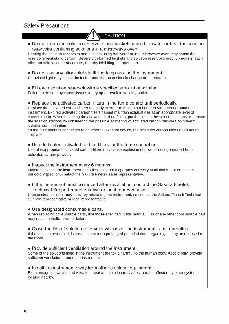
● Do not clean the solution reservoirs and baskets using hot water or heat the solution reservoirs containing solutions in a microwave oven.
Heating the solution reservoirs and baskets using hot water or in a microwave oven may cause the reservoirs/baskets to deform. Severely deformed baskets and solution reservoirs may rub against each other on side faces or at corners, thereby inhibiting the operation.
● Do not use any ultraviolet sterilizing lamp around the instrument. Ultraviolet light may cause the instrument characteristics to change or deteriorate.
● Fill each solution reservoir with a specified amount of solution. Failure to do so may cause tissues to dry up or result in staining problems.
● Replace the activated carbon filters in the fume control unit periodically. Replace the activated carbon filters regularly in order to maintain a better environment around the instrument. Expired activated carbon filters cannot maintain exhaust gas at an appropriate level of concentration. When replacing the activated carbon filters, put the lids on the solution stations or remove the solution stations by considering the possible scattering of activated carbon particles, to prevent solution contamination. * If the instrument is connected to an external exhaust device, the activated carbon filters need not be replaced.
● Use dedicated activated carbon filters for the fume control unit. Use of inappropriate activated carbon filters may cause explosion of powder dust generated from
activated carbon powder. ● Inspect the instrument every 6 months. Maintain/inspect the instrument periodically so that it operates correctly at all times. For details on periodic inspection, contact the Sakura Finetek sales representative.
● If the instrument must be moved after installation, contact the Sakura Finetek
Technical Support representative or local representative. Unexpected accident may occur by relocating the instrument, so contact the Sakura Finetek Technical Support representative or local representative.
● Use designated consumable parts. When replacing consumable parts, use those specified in this manual. Use of any other consumable part may result in malfunction or failure.
● Close the lids of solution reservoirs whenever the instrument is not operating. If the solution reservoir lids remain open for a prolonged period of time, organic gas may be released to the room.
● Provide sufficient ventilation around the instrument. Some of the solutions used in the instrument are toxic/harmful to the human body. Accordingly, provide sufficient ventilation around the instrument.
● Install the instrument away from other electrical equipment. Electromagnetic waves and vibration, heat and solution may affect and be affected by other systems located nearby.

Safety Precautions
(m)
CAUTION
● Provide a proper space around the instrument. Provide at least 10 cm of clearance around the instrument and make sure the power plug is installed so that it can be accessed at any time.
● Thoroughly check the installation location before installing the instrument. Install the instrument on a flat, non-slippery sturdy floor having a sufficient size. If the installation location is tilted or too small, unexpected accidents may occur.
● Do not use the instrument in a place subject to too low or high temperatures. Use it in a place where the temperature is stable in a range of 10C to 40C.
● Be sure to connect the power plug to a power outlet with grounding bar. Connect the power plug alone to a power outlet with grounding bar conforming to at least the Class D grounding specification. If the instrument is not grounded properly, fire or electric shock may result due to leak current.
● Lightning and power outage may cause the instrument to fail and stain process may
not be able to continue and adversely affect staining. If the power supply is unstable, use an uninterruptible power supply.
Lightning may cause the instrument to fail and damage the tissues. If the instrument will be used in a region where lightning damage is a possibility, use an uninterruptible power supply. If lightning has caused an irreparable damage to the instrument, take out the basket from the instrument and take an appropriate measure.
● Do not perform stain process if an extended period of power outage is scheduled.
Staining quality may drop. Staining problems may occur depending on when the power outage occurs.
In this case, use a uninterruptible power supply. If you find that the stain process has stopped due to an unexpected power outage lasting for an extended period of time, remove the baskets from the instrument and take appropriate action.
● Install the power cord and cables carefully by making sure the cord and cables will
not interfere with the work. Failure to do so may result in the operator tripping over the power cord and cables and sustaining injury.
● Securely connect the power cord and power outlet. If the power cord came off or the
power switch was turned off inadvertently, connect the power cord or turn on the power switch without delay.
If they are loosely connected, heat may be generated at the connected part, voltage drop can occur and the instrument may not operate normally. Furthermore, unexpected accidents or injuries can occur. Also, the tissues may be damaged when the power is cut off during processing.
● Handle the power cord with care. Also, be aware of damage caused by mice and
other small animals. To unplug the power cord from the power outlet, do not pull the cord, but hold the plug and then pull it out. Inspect the power cord periodically. If any damage is found in the exterior of the power cord, stop using it and contact the Sakura Finetek Technical Support representative or local representative.
● Before operating the instrument, be sure to check the electromagnetic environment. Example: Remove electrostatics from the operator and humidify the room.

Safety Precautions
(n)
CAUTION
● If an error (trouble) occurs, staining problems may occur. Immediately resolve the error, protect the tissues, and contact the Sakura Finetek Technical Support representative or local representative.
Connect an external alarm to prevent staining problems from happening when the instrument experiences problems. When introducing an external alarm, contact the Sakura Finetek Technical Support representative or local representative.
● Conduct a staining test before determining the staining conditions. ● Check the staining program before the operation. If a wrong staining program is
used, staining problems may occur. A wrong operation may interrupt the stain process or edit the program to a wrong one. If staining is started with a wrong program, staining problems may occur. Read this manual carefully and use the instrument correctly.
● Operating the instrument with an inappropriate temperature setting or time setting
(long/short) may cause staining problems. Conduct a verification test beforehand to confirm that staining can be performed properly. If you have any question regarding staining programs, contact the Sakura Finetek Technical Support representative or local representative.
● The allowable concentration limit of each substance in the work environment varies
depending on the air temperature, size of the room, additional load, if any, ventilation efficient y, etc.
If danger is suspected, the Instrument Control Manager should measure the concentration of the applicable substance in the area and confirm that the allowable limit in the work environment is not exceeded. Follow the standard concentration limits specified by the environmental regulation of the country/region in which the instrument is used.
● Solution may scatter and attach to your body while working. Be sure to wear
protective gears while working. In all operations including stain process, solution exchange, opening/closing of doors, cleaning and daily maintenance, the solutions used may scatter and attach to your body (eye, mucous membrane, skin, mouth, nose, etc.) or you may inhale their gases. Be sure to wear protective gears (gloves, organic solvent mask, goggles) while working.
● If any solution harmful to human health attached to your body or entered your mouth,
take an appropriate action according to the SDS of the solution. Wear protective gears (mask, gloves, goggles) during work in case anything goes wrong. Use protective gears that are resistant to all solutions on the solution list.
● You may accidentally touch an infectious source and operate the instrument with the
contaminated hands. Be sure to wear protective gears when operating the instrument.
If you have operated the instrument after handling a pathogen, disinfect the instrument properly. The disinfection method varies depending on the type of pathogen, so choose a method appropriate for the pathogen. Also, disinfect/sterilize or otherwise properly treat the protective gears used and then dispose of them as infectious waste. For the disposal method, follow the applicable regulation and guideline specified by each institution, country or region.
Safety Precautions
(o)
CAUTION
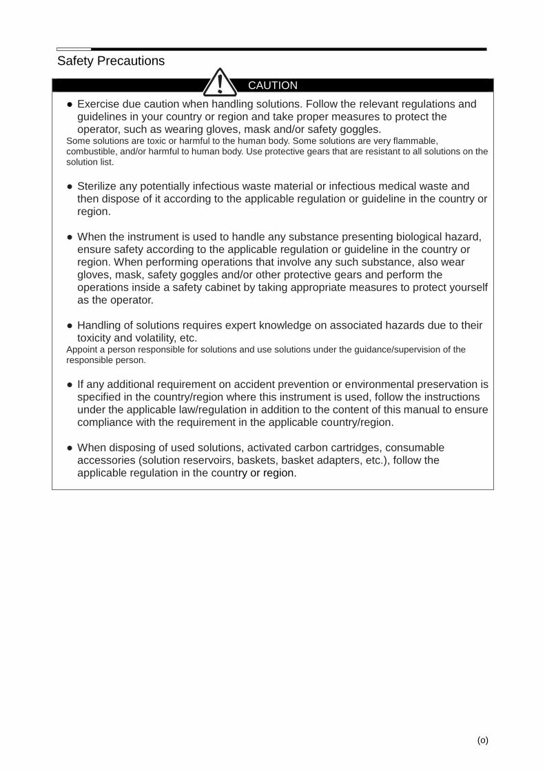
● Exercise due caution when handling solutions. Follow the relevant regulations and guidelines in your country or region and take proper measures to protect the operator, such as wearing gloves, mask and/or safety goggles.
Some solutions are toxic or harmful to the human body. Some solutions are very flammable, combustible, and/or harmful to human body. Use protective gears that are resistant to all solutions on the solution list.
● Sterilize any potentially infectious waste material or infectious medical waste and
then dispose of it according to the applicable regulation or guideline in the country or region.
● When the instrument is used to handle any substance presenting biological hazard,
ensure safety according to the applicable regulation or guideline in the country or region. When performing operations that involve any such substance, also wear gloves, mask, safety goggles and/or other protective gears and perform the operations inside a safety cabinet by taking appropriate measures to protect yourself as the operator.
● Handling of solutions requires expert knowledge on associated hazards due to their
toxicity and volatility, etc. Appoint a person responsible for solutions and use solutions under the guidance/supervision of the responsible person.
● If any additional requirement on accident prevention or environmental preservation is
specified in the country/region where this instrument is used, follow the instructions under the applicable law/regulation in addition to the content of this manual to ensure compliance with the requirement in the applicable country/region.
● When disposing of used solutions, activated carbon cartridges, consumable
accessories (solution reservoirs, baskets, basket adapters, etc.), follow the applicable regulation in the country or region.
(p)
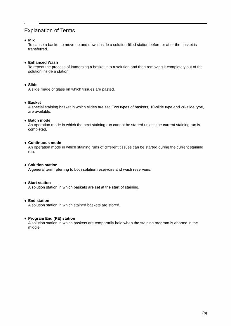
Explanation of Terms ● Mix
To cause a basket to move up and down inside a solution-filled station before or after the basket is transferred.
● Enhanced Wash
To repeat the process of immersing a basket into a solution and then removing it completely out of the solution inside a station.
● Slide
A slide made of glass on which tissues are pasted. ● Basket
A special staining basket in which slides are set. Two types of baskets, 10-slide type and 20-slide type, are available.
● Batch mode
An operation mode in which the next staining run cannot be started unless the current staining run is completed.
● Continuous mode
An operation mode in which staining runs of different tissues can be started during the current staining run.
● Solution station
A general term referring to both solution reservoirs and wash reservoirs. ● Start station
A solution station in which baskets are set at the start of staining. ● End station
A solution station in which stained baskets are stored. ● Program End (PE) station
A solution station in which baskets are temporarily held when the staining program is aborted in the middle.


Chapter 1 Basics of the System
1-1
Installation Method
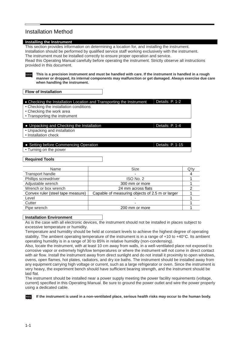
Installing the Instrument This section provides information on determining a location for, and installing the instrument. Installation should be performed by qualified service staff working exclusively with the instrument. The instrument must be installed correctly to ensure proper operation and service. Read this Operating Manual carefully before operating the instrument. Strictly observe all instructions provided in this document. This is a precision instrument and must be handled with care. If the instrument is handled in a rough
manner or dropped, its internal components may malfunction or get damaged. Always exercise due care when handling the instrument.
Flow of Installation
Checking the Installation Location and Transporting the Instrument Details: P. 1-2
• Checking the installation conditions • Checking the work area • Transporting the instrument
● Unpacking and Checking the Installation Details: P. 1-4
• Unpacking and installation • Installation check
● Setting before Commencing Operation Details: P. 1-15
• Turning on the power
Required Tools
Name Size Q'ty
Transport handle - 4
Phillips screwdriver ISO No. 2 1
Adjustable wrench 300 mm or more 1
Wrench or box wrench 24 mm across flats 2
Convex ruler (steel tape measure) Capable of measuring objects of 2.5 m or larger 1
Level - 1
Cutter - 1
Pipe wrench 200 mm or more 1
Installation Environment
As is the case with all electronic devices, the instrument should not be installed in places subject to excessive temperature or humidity. Temperature and humidity should be held at constant levels to achieve the highest degree of operating
stability. The ambient operating temperature of the instrument is in a range of +10 to +40C. Its ambient operating humidity is in a range of 30 to 85% in relative humidity (non-condensing). Also, locate the instrument, with at least 10 cm away from walls, in a well-ventilated place not exposed to corrosive vapor or extremely high/low temperatures or where the instrument will not come in direct contact with air flow. Install the instrument away from direct sunlight and do not install it proximity to open windows, ovens, open flames, hot plates, radiators, and dry ice baths. The instrument should be installed away from any equipment carrying high voltage or current, such as a large refrigerator or oven. Since the instrument is very heavy, the experiment bench should have sufficient bearing strength, and the instrument should be laid flat. The instrument should be installed near a power supply meeting the power facility requirements (voltage, current) specified in this Operating Manual. Be sure to ground the power outlet and wire the power properly using a dedicated cable. If the instrument is used in a non-ventilated place, serious health risks may occur to the human body.
Installation Method
1-2
Checking the Installation Condition
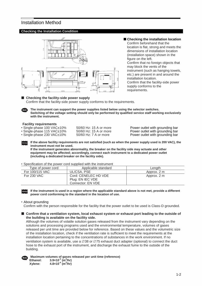
Checking the installation location
Confirm beforehand that the location is flat, strong and meets the dimensions of installation location (installation space) shown in the figure on the left. Confirm that no foreign objects that may block the vents of the instrument (such as hanging towels, etc.) are present in and around the installation location. Confirm that the facility-side power supply conforms to the requirements.
Checking the facility-side power supply
Confirm that the facility-side power supply conforms to the requirements.
The instrument can support the power supplies listed below using the selector switches. Switching of the voltage setting should only be performed by qualified service staff working exclusively with the instrument.
Facility requirements
• Single-phase 100 VAC±10% • Single-phase 115 VAC±10% • Single-phase 230 VAC±10%
50/60 Hz: 15 A or more 50/60 Hz: 15 A or more 50/60 Hz: 7 A or more
Power outlet with grounding bar Power outlet with grounding bar Power outlet with grounding bar
If the above facility requirements are not satisfied (such as when the power supply used is 200 VAC), the
instrument must not be used. If the instrument generates abnormality, the breaker on the facility side may actuate and other equipment may be affected; accordingly, connect each instrument to a dedicated power outlet (including a dedicated breaker on the facility side).
• Specification of the power cord supplied with the instrument
Type of power cord Applicable standard Length For 100/115 VAC UL/CSA, PSE Approx. 2 m For 230 VAC Cord: CENELEC HD VDE
Plug: EN IEC VDE Connector: EN VDE
Approx. 2 m
If the instrument is used in a region where the applicable standard above is not met, provide a different
power cord conforming to the standard in the location of use.
• About grounding
Confirm with the person responsible for the facility that the power outlet to be used is Class-D grounded. Confirm that a ventilation system, local exhaust system or exhaust port leading to the outside of
the building is available on the facility side. Although the volumes of volatile solution gases released from the instrument vary depending on the solutions and processing programs used and the environmental temperature, volumes of gases released per unit time are provided below for reference. Based on these values and the volumetric size of the installation location, check if the ventilation rate is sufficient to meet the requirements at the installation location pertaining to the concentrations of substances in the work environment. If no
ventilation system is available, use a 38 or 75 exhaust duct adapter (optional) to connect the duct hose to the exhaust port of the instrument, and discharge the exhaust fume to the outside of the building.
Maximum volumes of gases released per unit time (reference)
Ethanol: 3.9×10⁻³
(m3/hr)
Xylene: 4.8×10⁻⁴
(m3/hr)
Installation Method
1-3
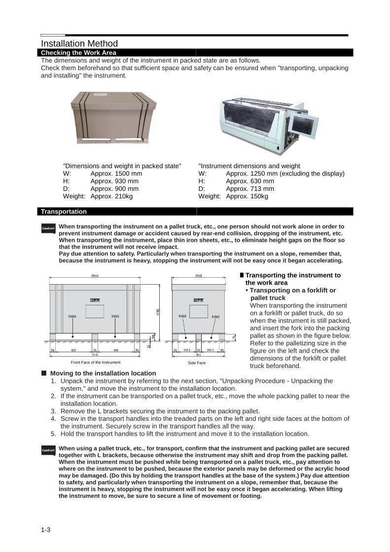
Checking the Work Area The dimensions and weight of the instrument in packed state are as follows. Check them beforehand so that sufficient space and safety can be ensured when "transporting, unpacking and installing" the instrument.
"Dimensions and weight in packed state" W: Approx. 1500 mm H: Approx. 930 mm D: Approx. 900 mm Weight: Approx. 210kg
"Instrument dimensions and weight W: Approx. 1250 mm (excluding the display) H: Approx. 630 mm D: Approx. 713 mm Weight: Approx. 150kg
Transportation
When transporting the instrument on a pallet truck, etc., one person should not work alone in order to
prevent instrument damage or accident caused by rear-end collision, dropping of the instrument, etc. When transporting the instrument, place thin iron sheets, etc., to eliminate height gaps on the floor so that the instrument will not receive impact. Pay due attention to safety. Particularly when transporting the instrument on a slope, remember that, because the instrument is heavy, stopping the instrument will not be easy once it began accelerating.
Transporting the instrument to
the work area • Transporting on a forklift or
pallet truck When transporting the instrument on a forklift or pallet truck, do so when the instrument is still packed, and insert the fork into the packing pallet as shown in the figure below. Refer to the palletizing size in the figure on the left and check the dimensions of the forklift or pallet truck beforehand.
Moving to the installation location 1. Unpack the instrument by referring to the next section, "Unpacking Procedure - Unpacking the
system," and move the instrument to the installation location. 2. If the instrument can be transported on a pallet truck, etc., move the whole packing pallet to near the
installation location. 3. Remove the L brackets securing the instrument to the packing pallet. 4. Screw in the transport handles into the treaded parts on the left and right side faces at the bottom of
the instrument. Securely screw in the transport handles all the way. 5. Hold the transport handles to lift the instrument and move it to the installation location.
When using a pallet truck, etc., for transport, confirm that the instrument and packing pallet are secured
together with L brackets, because otherwise the instrument may shift and drop from the packing pallet. When the instrument must be pushed while being transported on a pallet truck, etc., pay attention to where on the instrument to be pushed, because the exterior panels may be deformed or the acrylic hood may be damaged. (Do this by holding the transport handles at the base of the system.) Pay due attention to safety, and particularly when transporting the instrument on a slope, remember that, because the instrument is heavy, stopping the instrument will not be easy once it began accelerating. When lifting the instrument to move, be sure to secure a line of movement or footing.
Inlet
Front Face of the Instrument Side Face
Inlet Inlet Inlet

Installation Method
1-4
Unpacking Procedure
How to remove the instrument from the packing box that has been carried in, and remove the protective materials, is explained. To perform each work safely and correctly, be sure to follow the procedure specified herein. Confirm before unpacking the instrument, that the packing materials have not been damaged due to
external forces applied during transport. Two or more persons should always work together to unpack the instrument. Be careful not to damage/scratch the instrument when unpacking. When taking the accessory box out of the instrument, assume a natural posture.
Unpacking the System
1. Cut the bands with a cutting knife, etc. and remove the cap.
2. Remove the cushion materials put around the instrument, and take out the sleeves and polyethylene
bags. 3. Remove the cushion materials inserted into the front hood from both sides, lift the front hood, and take
out the cushion materials sandwiched between the front hood and the front door.
Cushion material Cushion material Cushion material
Cap
Sleeve
Ester band
Installation Method
1-5
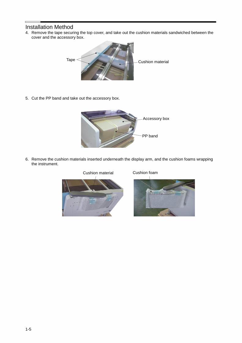
4. Remove the tape securing the top cover, and take out the cushion materials sandwiched between the cover and the accessory box.
5. Cut the PP band and take out the accessory box. 6. Remove the cushion materials inserted underneath the display arm, and the cushion foams wrapping
the instrument.
Cushion material Tape
Accessory box
PP band
Cushion material Cushion foam

Installation Method
1-6
Removing the Securing Members Inside the Instrument
1. Remove the cushion materials sandwiched between the robot arm and the rail. 2. Remove the tape securing the holder, and remove the cushion materials inserted underneath the
holder. 3. Remove the reinforcing cushion materials on the tray, and take out the cushion foam sheet and PP
band. 4. Remove all 3-position and 4-position reservoir trays stored in the system, and remove the tape securing
the cushion foam sheet and the water supply nozzle.
Tape Cushion material
Cushion material
Cushion material
Cushion material
Cushion material
PP band Cushion foam sheet
Cushion foam sheet Sheet securing the water supply nozzle
Installation Method
1-7
Switching the Power-supply Voltage Setting This instrument supports multiple voltages, but the setting on the instrument side must be switched
according to the power-supply voltage. If the instrument is used without switching the voltage setting, not only the instrument will break down, but the user may also be exposed to danger; accordingly, contact the Sakura Finetek Technical Support representative or local representative when the instrument is installed to switch the voltage setting according to the voltage on the facility side. The factory setting is 230 V.
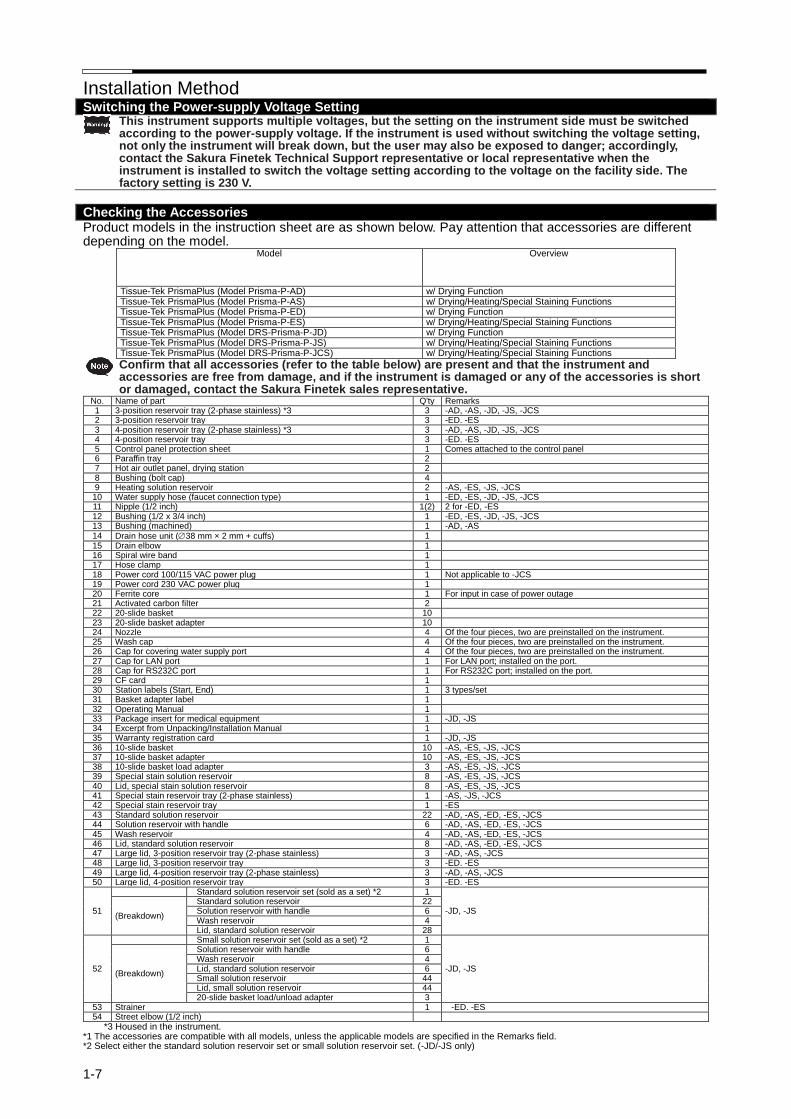
Checking the Accessories Product models in the instruction sheet are as shown below. Pay attention that accessories are different depending on the model.
Model Overview
Tissue-Tek PrismaPlus (Model Prisma-P-AD) w/ Drying Function Tissue-Tek PrismaPlus (Model Prisma-P-AS) w/ Drying/Heating/Special Staining Functions Tissue-Tek PrismaPlus (Model Prisma-P-ED) w/ Drying Function Tissue-Tek PrismaPlus (Model Prisma-P-ES) w/ Drying/Heating/Special Staining Functions Tissue-Tek PrismaPlus (Model DRS-Prisma-P-JD) w/ Drying Function Tissue-Tek PrismaPlus (Model DRS-Prisma-P-JS) w/ Drying/Heating/Special Staining Functions Tissue-Tek PrismaPlus (Model DRS-Prisma-P-JCS) w/ Drying/Heating/Special Staining Functions
Confirm that all accessories (refer to the table below) are present and that the instrument and accessories are free from damage, and if the instrument is damaged or any of the accessories is short or damaged, contact the Sakura Finetek sales representative.
No. Name of part Q'ty Remarks 1 3-position reservoir tray (2-phase stainless) *3 3 -AD, -AS, -JD, -JS, -JCS 2 3-position reservoir tray 3 -ED. -ES 3 4-position reservoir tray (2-phase stainless) *3 3 -AD, -AS, -JD, -JS, -JCS 4 4-position reservoir tray 3 -ED. -ES 5 Control panel protection sheet 1 Comes attached to the control panel 6 Paraffin tray 2 7 Hot air outlet panel, drying station 2 8 Bushing (bolt cap) 4 9 Heating solution reservoir 2 -AS, -ES, -JS, -JCS 10 Water supply hose (faucet connection type) 1 -ED, -ES, -JD, -JS, -JCS 11 Nipple (1/2 inch) 1(2) 2 for -ED, -ES 12 Bushing (1/2 x 3/4 inch) 1 -ED, -ES, -JD, -JS, -JCS 13 Bushing (machined) 1 -AD, -AS 14 Drain hose unit (38 mm × 2 mm + cuffs) 1 15 Drain elbow 1 16 Spiral wire band 1 17 Hose clamp 1 18 Power cord 100/115 VAC power plug 1 Not applicable to -JCS 19 Power cord 230 VAC power plug 1 20 Ferrite core 1 For input in case of power outage 21 Activated carbon filter 2 22 20-slide basket 10 23 20-slide basket adapter 10 24 Nozzle 4 Of the four pieces, two are preinstalled on the instrument. 25 Wash cap 4 Of the four pieces, two are preinstalled on the instrument. 26 Cap for covering water supply port 4 Of the four pieces, two are preinstalled on the instrument. 27 Cap for LAN port 1 For LAN port; installed on the port. 28 Cap for RS232C port 1 For RS232C port; installed on the port. 29 CF card 1 30 Station labels (Start, End) 1 3 types/set 31 Basket adapter label 1 32 Operating Manual 1 33 Package insert for medical equipment 1 -JD, -JS 34 Excerpt from Unpacking/Installation Manual 1 35 Warranty registration card 1 -JD, -JS 36 10-slide basket 10 -AS, -ES, -JS, -JCS 37 10-slide basket adapter 10 -AS, -ES, -JS, -JCS 38 10-slide basket load adapter 3 -AS, -ES, -JS, -JCS 39 Special stain solution reservoir 8 -AS, -ES, -JS, -JCS 40 Lid, special stain solution reservoir 8 -AS, -ES, -JS, -JCS 41 Special stain reservoir tray (2-phase stainless) 1 -AS, -JS, -JCS 42 Special stain reservoir tray 1 -ES 43 Standard solution reservoir 22 -AD, -AS, -ED, -ES, -JCS 44 Solution reservoir with handle 6 -AD, -AS, -ED, -ES, -JCS 45 Wash reservoir 4 -AD, -AS, -ED, -ES, -JCS 46 Lid, standard solution reservoir 8 -AD, -AS, -ED, -ES, -JCS 47 Large lid, 3-position reservoir tray (2-phase stainless) 3 -AD, -AS, -JCS 48 Large lid, 3-position reservoir tray 3 -ED. -ES 49 Large lid, 4-position reservoir tray (2-phase stainless) 3 -AD, -AS, -JCS 50 Large lid, 4-position reservoir tray 3 -ED. -ES
51
Standard solution reservoir set (sold as a set) *2 1
-JD, -JS (Breakdown)
Standard solution reservoir 22 Solution reservoir with handle 6 Wash reservoir 4 Lid, standard solution reservoir 28
52
Small solution reservoir set (sold as a set) *2 1
-JD, -JS (Breakdown)
Solution reservoir with handle 6 Wash reservoir 4 Lid, standard solution reservoir 6 Small solution reservoir 44 Lid, small solution reservoir 44 20-slide basket load/unload adapter 3
53 Strainer 1 -ED. -ES 54 Street elbow (1/2 inch)
*3 Housed in the instrument. *1 The accessories are compatible with all models, unless the applicable models are specified in the Remarks field. *2 Select either the standard solution reservoir set or small solution reservoir set. (-JD/-JS only)

Installation Method
1-8
*3 Housed in the instrument.

Installation Method
1-9
①
②
Checking the Installation (Securing the Instrument)
1. Confirm that the location where the instrument will be installed is flat and sufficiently strong. 2. Two or more persons work together to lift the instrument and move it to the installation location. If the
instrument rattles or is inclined too much when installed, adjust the level adjusters underneath the instrument. Also when the instrument is linked to the Tissue-Tek Film or Tissue-Tek Glass g2, use the level adjusters underneath the instrument to adjust the height and inclination of the instrument.
3. Once the instrument has been installed, remove the transport handles and install the attached bushing (bolt caps) in the threaded parts on the system.
Installing the parts around the instrument
● Attach the water supply hose connect it to a water supply facility (tap water supply) meeting the
following conditions: Pressure: Dynamic pressure = 0.098 to 0.441 MPa
Maximum static pressure = 0.74 MPa
Temperature: 30C max. (non-freezing) Faucet: A faucet of general shape having a tip of 12 mm to 17 mm in size. (The water
supply hose cannot be connected to a faucet of any other size or to a special shaped faucet such as chemical faucet or aerator faucet.)
Facility requirements: Use a facility meeting the following items in order to prevent health damage caused by flow-back: [1] Water supply facility not directly connected to public water pipes [2] Water supply facility not directly connected to a water supply system
used for drinking water, etc. [3] Water supply facility designed to prevent flow-back caused by
reverse-siphoning • Water supply facility equipped with a flow-back protection mechanism meeting the law of each country/region
1. Connect a nipple o the water supply port on the instrument via a bushing, and then screw the threaded
part of the water supply hose into the bushing. 2. Pull the flange on the other end of the water supply hose toward the hose and separate the water tap
joint. 3. Loosen the four screws on the water tap joint. 4. Tighten the four screws uniformly while pressing the black rubber in the water tap joint against the tip of
the water faucet. 5. Turn and tighten the nipple. 6. Insert the water supply hose into the water tap joint with the flange pulled back. 7. Gently pull the water supply hose by hand to confirm that it does not come off from the water tap joint. ]
Threaded part of the water hose
How to separate the water tap joint
[1]
[2]
Water tap joint Flange on the water supply hose
Nipple
Water supply port Bushing Nipple
Installation Method
1-10
Spiral wire band
Drain hose
Drain port
Drain elbow Hose clamp
Drain hose
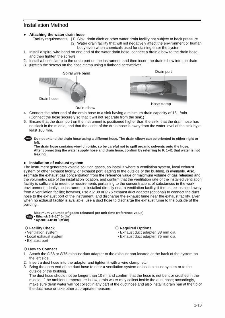
● Attaching the water drain hose Facility requirements: [1] Sink, drain ditch or other water drain facility not subject to back pressure
[2] Water drain facility that will not negatively affect the environment or human body even when chemicals used for staining enter the system
1. Install a spiral wire band on one end of the water drain hose, connect a drain elbow to the drain hose, and then tighten the screws.
2. Install a hose clamp to the drain port on the instrument, and then insert the drain elbow into the drain port. 3. Tighten the screws on the hose clamp using a flathead screwdriver.
4. Connect the other end of the drain hose to a sink having a minimum drain capacity of 15 L/min.
(Connect the hose securely so that it will not separate from the sink.) 5. Ensure that the drain port on the instrument is positioned higher than the sink, that the drain hose has
no slack in the middle, and that the outlet of the drain hose is away from the water level of the sink by at least 100 mm.
Do not extend the drain hose using a different hose. The drain elbow can be oriented to either right or
left. The drain hose contains vinyl chloride, so be careful not to spill organic solvents onto the hose. After connecting the water supply hose and drain hose, confirm by referring to P. 1-41 that water is not leaking.
● Installation of exhaust system The instrument generates volatile solution gases, so install it where a ventilation system, local exhaust system or other exhaust facility, or exhaust port leading to the outside of the building, is available. Also, estimate the exhaust gas concentration from the reference value of maximum volume of gas released and the volumetric size of the installation location, and confirm that the ventilation rate of the installed ventilation facility is sufficient to meet the requirements pertaining to the concentrations of substances in the work environment. Ideally the instrument is installed directly near a ventilation facility, if it must be installed away from a ventilation facility; however, use a 38 or 75 exhaust duct adapter (optional) to connect the duct hose to the exhaust port of the instrument, and discharge the exhaust fume near the exhaust facility. Even when no exhaust facility is available, use a duct hose to discharge the exhaust fume to the outside of the building. Maximum volumes of gases released per unit time (reference value)
• Ethanol: 3.9×10⁻³ (m
3/hr)
• Xylene: 4.8×10⁻⁴ (m
3/hr)
Facility Check • Ventilation system • Local exhaust system • Exhaust port
Required Options • Exhaust duct adapter, 38 mm dia. • Exhaust duct adapter, 75 mm dia.
How to Connect
1. Attach the 38 or 75 exhaust duct adapter to the exhaust port located at the back of the system on the left side.
2. Insert a duct hose into the adapter and tighten it with a wire clamp, etc. 3. Bring the open end of the duct hose to near a ventilation system or local exhaust system or to the
outside of the building. The duct hose should not be longer than 10 m, and confirm that the hose is not bent or crushed in the middle. If the ambient temperature is low, drain water may collect inside the duct hose; accordingly, make sure drain water will not collect in any part of the duct hose and also install a drain pan at the tip of the duct hose or take other appropriate measure.
Installation Method
1-11
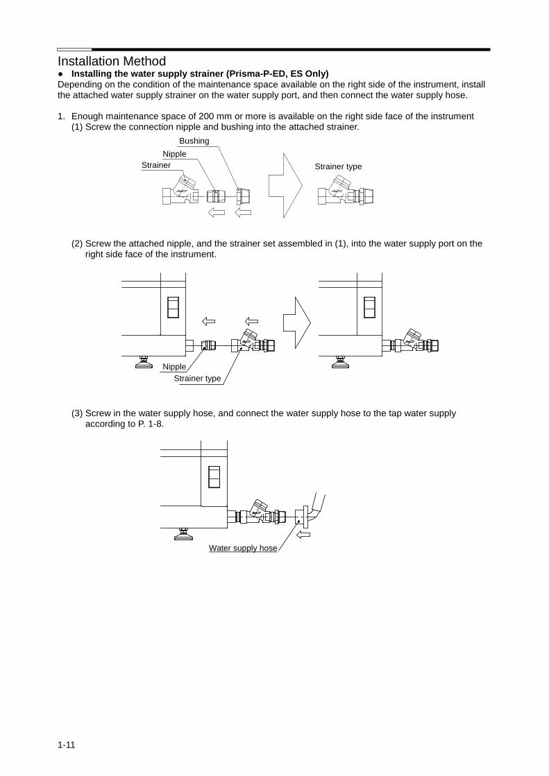
● Installing the water supply strainer (Prisma-P-ED, ES Only) Depending on the condition of the maintenance space available on the right side of the instrument, install the attached water supply strainer on the water supply port, and then connect the water supply hose. 1. Enough maintenance space of 200 mm or more is available on the right side face of the instrument
(1) Screw the connection nipple and bushing into the attached strainer.
(2) Screw the attached nipple, and the strainer set assembled in (1), into the water supply port on the right side face of the instrument.
(3) Screw in the water supply hose, and connect the water supply hose to the tap water supply according to P. 1-8.
Nipple
Bushing
Strainer Strainer type
Nipple
Strainer type
Water supply hose

Installation Method
1-12
2. No more than 100 to 200 mm of maintenance space is available on the right side face of the instrument In this case, approx. 35 mm of space may be required at the back of the instrument. (1) Screw the connection nipple and bushing into the attached strainer.
(2) Screw the attached nipple and street elbow into the water supply port on the right side face of the instrument.
(3) Screw in the strainer set assembled in (1).
(4) Screw in the water supply hose, and connect the water supply hose to the tap water supply according to P. 1-8.
Water supply hose
Nipple
Street elbow
Nipple
Strainer
Bushing
Strainer type
Strainer type
Installation Method
1-13
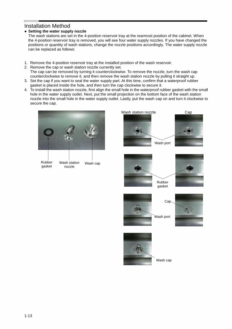
● Setting the water supply nozzle The wash stations are set in the 4-position reservoir tray at the rearmost position of the cabinet. When the 4-position reservoir tray is removed, you will see four water supply nozzles. If you have changed the positions or quantity of wash stations, change the nozzle positions accordingly. The water supply nozzle can be replaced as follows:
1. Remove the 4-position reservoir tray at the installed position of the wash reservoir. 2. Remove the cap or wash station nozzle currently set. The cap can be removed by turning it counterclockwise. To remove the nozzle, turn the wash cap
counterclockwise to remove it, and then remove the wash station nozzle by pulling it straight up. 3. Set the cap if you want to seal the water supply part. At this time, confirm that a waterproof rubber
gasket is placed inside the hole, and then turn the cap clockwise to secure it. 4. To install the wash station nozzle, first align the small hole in the waterproof rubber gasket with the small
hole in the water supply outlet. Next, put the small projection on the bottom face of the wash station nozzle into the small hole in the water supply outlet. Lastly, put the wash cap on and turn it clockwise to secure the cap.
Wash station nozzle Cap
Wash station nozzle
Rubber gasket
Wash cap
Cap
Rubber gasket
Wash port
Wash port
Wash cap
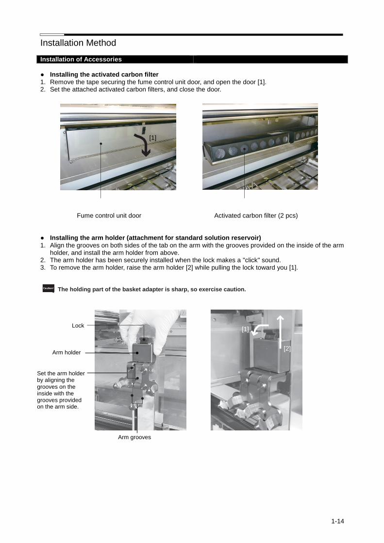
Installation Method
1-14
Installation of Accessories
● Installing the activated carbon filter 1. Remove the tape securing the fume control unit door, and open the door [1]. 2. Set the attached activated carbon filters, and close the door. Fume control unit door Activated carbon filter (2 pcs) ● Installing the arm holder (attachment for standard solution reservoir) 1. Align the grooves on both sides of the tab on the arm with the grooves provided on the inside of the arm
holder, and install the arm holder from above. 2. The arm holder has been securely installed when the lock makes a "click" sound. 3. To remove the arm holder, raise the arm holder [2] while pulling the lock toward you [1]. The holding part of the basket adapter is sharp, so exercise caution.
Arm grooves
[1]
Lock
Arm holder
Set the arm holder by aligning the grooves on the inside with the grooves provided on the arm side.
[1]
[2]

Installation Method
1-15
● Installing each tray
Set each tray with the two holes provided on the outer side of the handles on both sides of the tray (see the figure below) facing the rear. The position of each tray is shown below. Trays cannot be placed in the positions filled with gray.
3-position reservoir tray (for standard/small solution reservoirs)
4-position reservoir tray (for standard/small solution reservoirs)
Special stain reservoir tray (for special stain solution reservoirs)
Hole Hole
Hole Hole
Hole Hole
Back
Near side
Back
Near side
Back
Near side
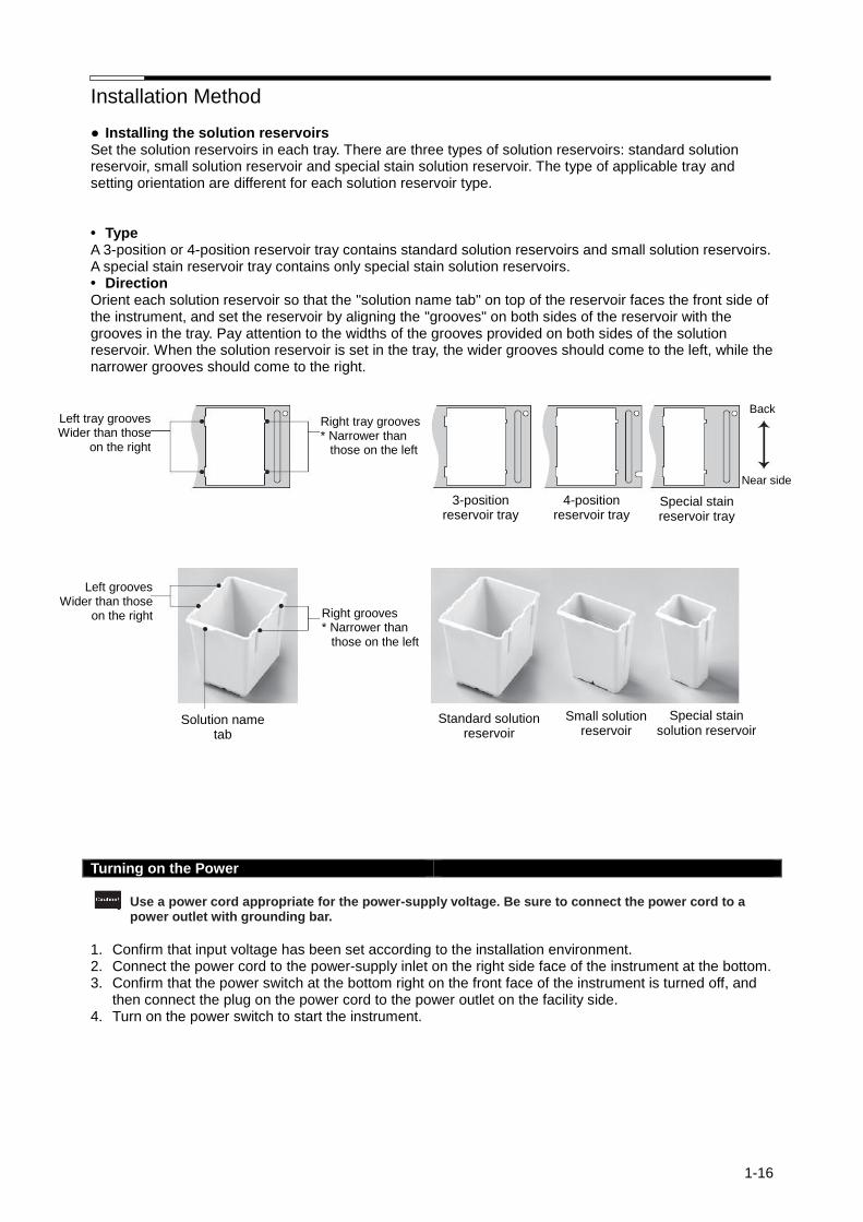
Installation Method
1-16
● Installing the solution reservoirs Set the solution reservoirs in each tray. There are three types of solution reservoirs: standard solution reservoir, small solution reservoir and special stain solution reservoir. The type of applicable tray and setting orientation are different for each solution reservoir type. • Type A 3-position or 4-position reservoir tray contains standard solution reservoirs and small solution reservoirs. A special stain reservoir tray contains only special stain solution reservoirs. • Direction Orient each solution reservoir so that the "solution name tab" on top of the reservoir faces the front side of the instrument, and set the reservoir by aligning the "grooves" on both sides of the reservoir with the grooves in the tray. Pay attention to the widths of the grooves provided on both sides of the solution reservoir. When the solution reservoir is set in the tray, the wider grooves should come to the left, while the narrower grooves should come to the right.
Turning on the Power
Use a power cord appropriate for the power-supply voltage. Be sure to connect the power cord to a
power outlet with grounding bar.
1. Confirm that input voltage has been set according to the installation environment. 2. Connect the power cord to the power-supply inlet on the right side face of the instrument at the bottom. 3. Confirm that the power switch at the bottom right on the front face of the instrument is turned off, and
then connect the plug on the power cord to the power outlet on the facility side. 4. Turn on the power switch to start the instrument.
4-position reservoir tray
Left tray grooves Wider than those
on the right
Right tray grooves * Narrower than
those on the left
Back
3-position reservoir tray
Special stain reservoir tray
Near side
Standard solution reservoir
Small solution reservoir
Special stain solution reservoir
Right grooves * Narrower than
those on the left
Left grooves Wider than those
on the right
Solution name tab
4-position reservoir tray

1-17
Specification "Prisma-P-AD/AS"
General name Automated slide stainer
Brand name Tissue-Tek Prisma®Plus
Type Prisma-P-AD Prisma-P-AS
Product code 6170 6171
Manufacturing license number 20B2X00014000034
Dimensions 1250 (W) x 713 (D) x 630 (H) mm (excluding the control monitor)
Weight Approximately 150 kg
Rated power supply Single-phase 115 VAC ± 10%, 50/60 Hz, 11 Amps
Power consumption 1000 VA
Electric shock protection Class I, overvoltage category II
Pollution degree Pollution degree I
Capabilities
Stain process Batch mode: 60, 20 or 10 slides Continuous mode: Up to 11 slides can be set in the system.
Staining programs Up to 5 programs can be stored. One program can consist of up to 50 steps.
Standard solution name Up to 100 solution names can be stored.
Solution configuration name Up to 50 solution configurations can be stored.
Drying station Temperature setting range: 30 to 65C
Heating station - Temperature setting range: 30 to 70C
Required facilities
Power supply
Voltage = Rated voltage 10%, 50/60 Hz
Current capacity = Rated current min.
Grounding = Comes with grounding bar conforming to class D grounding
Water supply
Water = Tap water
Pressure
Dynamic water = 0.098 to 0.441 MPa
Maximum static pressure = 0.74 MPa
Temperature = 30C max. (non-freezing)
Nominal pipe diameter = 15A (1/2 in) min.
Drain
Method = Indirect draining
Drain capacity = 15 L per minute min.
Nominal pipe diameter = 40A (1-1/2 in) min.
Operating environment
Ambient temperature 10 to 40C
Relative humidity 30 to 85% (non-condensing)
Storage environment
Ambient temperature -10 to 65C (instrument interior must be drained.)
Relative humidity 20 to 90% (non-condensing)
Vibration/drop
Drop test JISZ0200:2013 (Level 1)
Vibration test JISZ0232:2004 (Standard of Truck Transportation)
Noise 65 dB or less (A characteristics)
Law and conforming standard
Law FDA Class 1
Electrical safety evaluation
UL 61010-1:2012
CAN/CSA-C22.2 No. 61010-1-12: 2012
CAN/CSA-C22.2 No. 61010-2-010-04: 2014
CAN/CSA-C22.2 No. 61010-2-101-04: 2014
Risk management ISO 14971: 2007
IEC 62366: 2007
Medical equipment software IEC 62304: 2006
Quality management ISO 13485: 2003
Electromagnetic compatibility
IEC61326-2-6:2005
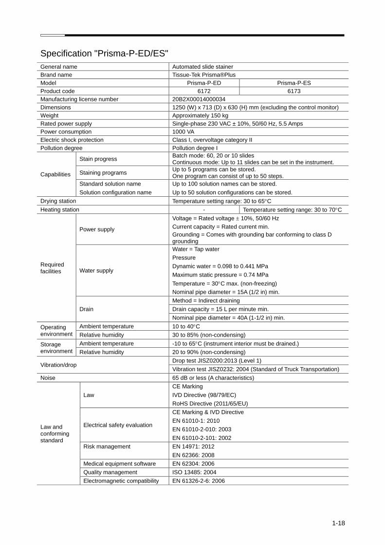
1-18
Specification "Prisma-P-ED/ES"
General name Automated slide stainer
Brand name Tissue-Tek Prisma®Plus
Model Prisma-P-ED Prisma-P-ES
Product code 6172 6173
Manufacturing license number 20B2X00014000034
Dimensions 1250 (W) x 713 (D) x 630 (H) mm (excluding the control monitor)
Weight Approximately 150 kg
Rated power supply Single-phase 230 VAC ± 10%, 50/60 Hz, 5.5 Amps
Power consumption 1000 VA
Electric shock protection Class I, overvoltage category II
Pollution degree Pollution degree I
Capabilities
Stain progress Batch mode: 60, 20 or 10 slides Continuous mode: Up to 11 slides can be set in the instrument.
Staining programs Up to 5 programs can be stored. One program can consist of up to 50 steps.
Standard solution name Up to 100 solution names can be stored.
Solution configuration name Up to 50 solution configurations can be stored.
Drying station Temperature setting range: 30 to 65C
Heating station - Temperature setting range: 30 to 70C
Required facilities
Power supply
Voltage = Rated voltage 10%, 50/60 Hz
Current capacity = Rated current min.
Grounding = Comes with grounding bar conforming to class D grounding
Water supply
Water = Tap water
Pressure
Dynamic water = 0.098 to 0.441 MPa
Maximum static pressure = 0.74 MPa
Temperature = 30C max. (non-freezing)
Nominal pipe diameter = 15A (1/2 in) min.
Drain
Method = Indirect draining
Drain capacity = 15 L per minute min.
Nominal pipe diameter = 40A (1-1/2 in) min.
Operating environment
Ambient temperature 10 to 40C
Relative humidity 30 to 85% (non-condensing)
Storage environment
Ambient temperature -10 to 65C (instrument interior must be drained.)
Relative humidity 20 to 90% (non-condensing)
Vibration/drop Drop test JISZ0200:2013 (Level 1)
Vibration test JISZ0232: 2004 (Standard of Truck Transportation)
Noise 65 dB or less (A characteristics)
Law and conforming standard
Law
CE Marking
IVD Directive (98/79/EC)
RoHS Directive (2011/65/EU)
Electrical safety evaluation
CE Marking & IVD Directive
EN 61010-1: 2010
EN 61010-2-010: 2003
EN 61010-2-101: 2002
Risk management EN 14971: 2012
EN 62366: 2008
Medical equipment software EN 62304: 2006
Quality management ISO 13485: 2004
Electromagnetic compatibility EN 61326-2-6: 2006

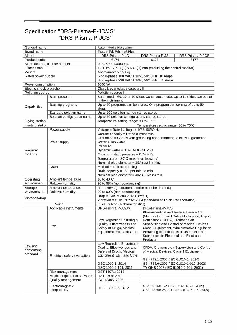
1-18
Specification "DRS-Prisma-P-JD/JS" "DRS-Prisma-P-JCS"
General name Automated slide stainer
Brand name Tissue-Tek Prisma®Plus
Model DRS-Prisma-P-JD DRS-Prisma-P-JS DRS-Prisma-P-JCS
Product code 6174 6175 6177
Manufacturing license number 20B2X00014000034
Dimensions 1250 (W) x 713 (D) x 630 (H) mm (excluding the control monitor)
Weight Approximately 150 kg
Rated power supply Single-phase 100 VAC ± 10%, 50/60 Hz, 10 Amps
Single-phase 230 VAC ± 10%, 50/60 Hz, 5.5 Amps
Power consumption 1000 VA
Electric shock protection Class I, overvoltage category II
Pollution degree Pollution degree I
Capabilities
Stain process Batch mode: 60, 20 or 10 slides Continuous mode: Up to 11 slides can be set in the instrument .
Staining programs Up to 50 programs can be stored. One program can consist of up to 50 steps.
Standard solution name Up to 100 solution names can be stored.
Solution configuration name Up to 50 solution configurations can be stored.
Drying station Temperature setting range: 30 to 65C
Heating station - Temperature setting range: 30 to 70C
Required facilities
Power supply Voltage = Rated voltage 10%, 50/60 Hz
Current capacity = Rated current min.
Grounding = Comes with grounding bar conforming to class D grounding
Water supply Water = Tap water
Pressure
Dynamic water = 0.098 to 0.441 MPa
Maximum static pressure = 0.74 MPa
Temperature = 30C max. (non-freezing)
Nominal pipe diameter = 15A (1/2 in) min.
Drain Method = Indirect draining
Drain capacity = 15 L per minute min.
Nominal pipe diameter = 40A (1-1/2 in) min.
Operating environment
Ambient temperature 10 to 40C
Relative humidity 30 to 85% (non-condensing)
Storage environment
Ambient temperature -10 to 65C (instrument interior must be drained.)
Relative humidity 20 to 90% (non-condensing)
Vibration/drop Drop testJISZ0200:2013 (Level 1)
Vibration test JIS Z0232: 2004 (Standard of Truck Transportation)
Noise 65 dB or less (A characteristics)
Law and conforming standard
Applicable instruments DRS-Prisma-P-JD/JS DRS-Prisma-P-JCS
Law
Law Regarding Ensuring of Quality, Effectiveness and Safety of Drugs, Medical Equipment, Etc., and Other
Pharmaceutical and Medical Device Act (Manufacturing and Sales Notification, Export Notification), CFDA, Ordinance on Supervision and Control of Medical Devices, Class 1 Equipment, Administrative Regulation Pertaining to Limitations of Use of Harmful Substances in Electrical and Electronic Products
Electrical safety evaluation
Law Regarding Ensuring of Quality, Effectiveness and Safety of Drugs, Medical Equipment, Etc., and Other
CFDA, Ordinance on Supervision and Control of Medical Devices, Class 1 Equipment
GB 4793.1-2007 (IEC 61010-1: 2010)
JISC 1010-1: 2014 GB 4793.6-2006 (IEC 61010-2-010: 2003)
JISC 1010-2-101: 2013 YY 0648-2008 (IEC 61010-2-101: 2002)
Risk management JIST 14971: 2012
Medical equipment software JIST 2304: 2012
Quality management ISO 13485: 2005
Electromagnetic compatibility
JISC 1806-2-6: 2012 GB/T 18268.1-2010 (IEC 61326-1: 2005) GB/T 18268.26-2010 (IEC 61326-2-6: 2005)
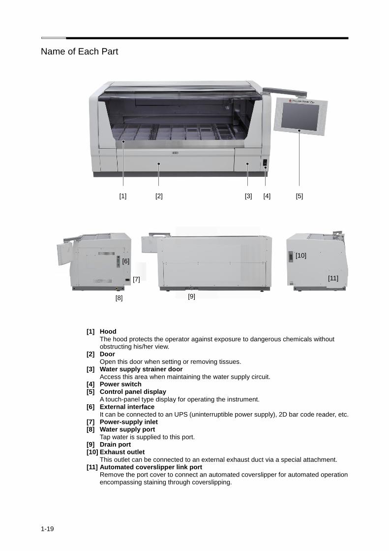
1-19
Name of Each Part
[1] [2] [3] [4] [5]
[1] Hood The hood protects the operator against exposure to dangerous chemicals without obstructing his/her view.
[2] Door Open this door when setting or removing tissues.
[3] Water supply strainer door Access this area when maintaining the water supply circuit.
[4] Power switch [5] Control panel display
A touch-panel type display for operating the instrument. [6] External interface
It can be connected to an UPS (uninterruptible power supply), 2D bar code reader, etc. [7] Power-supply inlet [8] Water supply port
Tap water is supplied to this port. [9] Drain port [10] Exhaust outlet
This outlet can be connected to an external exhaust duct via a special attachment. [11] Automated coverslipper link port
Remove the port cover to connect an automated coverslipper for automated operation encompassing staining through coverslipping.
[6]
[7]
[8] [9]
[10]
[11]

Name of Each Part
1-20
[12] Solution reservoir [13] Wash station
Up to 4 wash station. [14] Drying station [15] Heating station
Heating stations permit special stain runs that require heating. [16] Water supply handle
Use this handle to adjust the water flow rate. [17] Fume control unit
Activated carbon filters are part of the unit. [18] Robotic arm
The function of robotic arms is to move slide basket. [19] CF card slot
This sets a CF card in slot.
[12]
[17] [18] [19]
[13] [14] [15] [16]
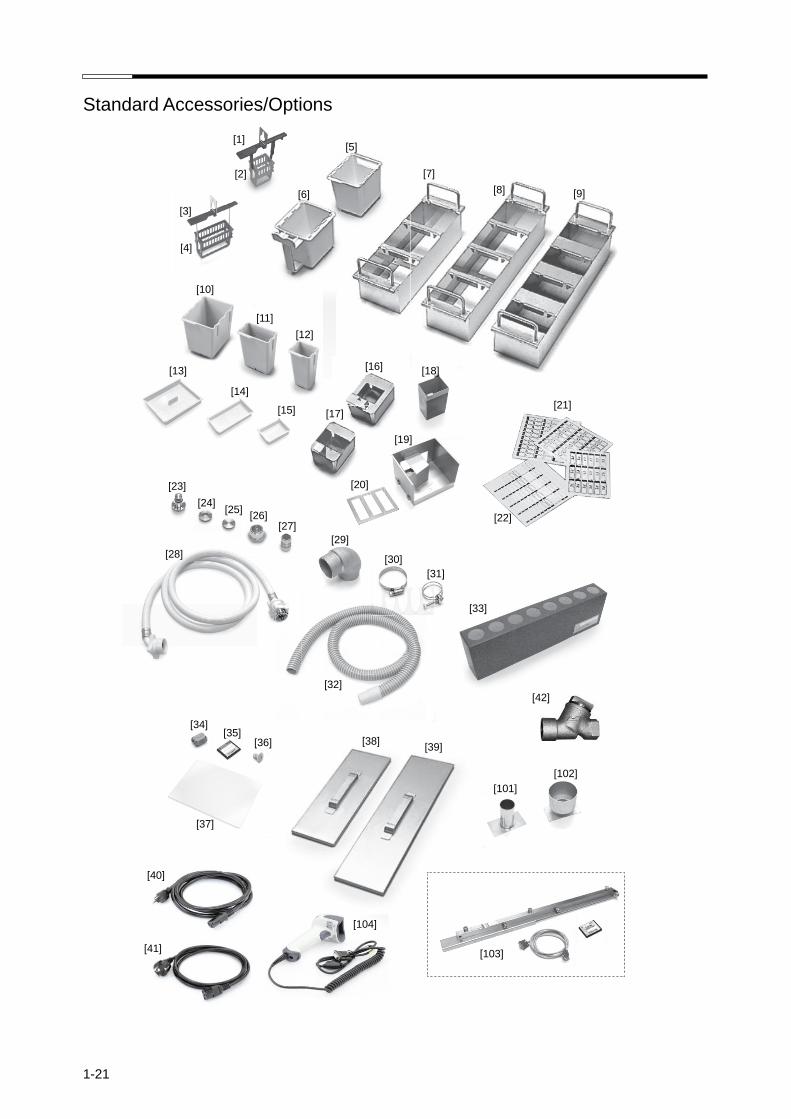
1-21
Standard Accessories/Options
[1]
[7]
[33]
[31]
[10]
[11]
[6]
[2]
[3]
[4]
[5]
[8] [9]
[12]
[16] [13]
[14]
[15] [17]
[18]
[19]
[20]
[21]
[22]
[23]
[24] [25]
[26] [27]
[29]
[28] [30]
[32]
[34] [35]
[36]
[37]
[38] [39]
[101]
[102]
[40]
[41]
[104]
[103]
[42]

Standard Accessories/Options
1-22
* (1) Preinstalled inside the instrument. (2) Pre-attached on the control panel screen. (3) Of the four pieces, two are preinstalled on the instrument. (4) Select either the standard solution reservoir set or small solution reservoir set. (5) Pre-installed on each port.
No. Product/part name Product code Part number AD AS ED ES JD JS JCS
6170 6171 6172 6173 6174 6175 6177 Q'ty
1 10-slide basket adapter 6138 K24-418-01 - 10 - 10 - 10 10 2 10-slide basket 6137 K24-411-00 - 10 - 10 - 10 10 3 20-slide basket adapter 6136 K24-408-01 10 10 10 10 10 10 10 4 20-slide basket 4768 K16-500-08 10 10 10 10 10 10 10 5 Wash reservoir 6149 K24-403-01 4 4 4 4 - - 4 6 Solution reservoir with handle 6148 K24-400-00 6 6 6 6 - - 6 7 3-position reservoir tray 6152 F6-02-7300 - - 3
(1) 3
(1) - - -
8 4-position reservoir tray 6154 F6-02-7400 - - 3(1)
3(1)
- - - 9 Special stain reservoir tray 6156 K24-147-02 - - - 1 - - -
10 Standard solution reservoir 6147 K24-401-01 22 22 22 22 - - 22 11 Small solution reservoir - K24-402-01 - - - - - - - 12 Special stain solution reservoir 6140 K24-404-00 - 8 - 8 - 8 9 13 Lid, standard solution reservoir 6151 K24-405-00 8 8 8 8 - - 8 14 Lid, small solution reservoir 6146 K24-406-00 - - - - - - - 15 Lid, special stain reservoir 6144 K24-407-00 - 8 - 8 - 8 8 16 10-slide basket load/unload adapter 6139 K24-488-03 - 3 - 3 - 3 3 17 20-slide basket load adapter 6135 K24-491-01 - - - - - - - 18 Heating solution reservoir 6141 K24-503-01 - 2 - 2 - 2 2 19 Paraffin tray - K24-531-04 2 2 2 2 2 2 2 20 Hot air outlet panel, drying station - K24-535-00 2 2 2 2 2 2 2 21 Station labels (Start, End) 6161 F6-02-8400 1 1 1 1 1 1 1 22 Basket adapter label 6162 K24-712-00 1 1 1 1 1 1 1 23 Nozzle - K24-430-01 4
(3) 4
(3) 4
(3) 4
(3) 4
(3) 4
(3) 4
(3)
24 Wash cap - K24-433-00 4(3)
4(3)
4(3)
4(3)
4(3)
4(3)
4(3)
25 Cap for covering water supply port - K24-437-00 4
(3) 4
(3) 4
(3) 4
(3) 4
(3) 4
(3) 4
(3)
26 Nipple (1/2 inch) - A6-30-0040 1 1 2 2 1 1 2 27 Bushing (1/2 x 3/4 inch) - A6-34-5160 - - 1 1 1 1 1 28 Water supply hose (faucet connection type) - B7-44-0030 - - 1 1 1 1 1 29 Drain elbow - K23-291-00 1 1 1 1 1 1 1 30 Hose clamp - D9-00-0159 1 1 1 1 1 1 1 31 Spiral wire band - D9-00-0146 1 1 1 1 1 1 1 32 Drain hose unit (38 mm x 2 m + cuffs) - K24-094-00 1 1 1 1 1 1 1 33 Activated carbon filters 6160 K24-467-00 2 2 2 2 2 2 2 34 Ferrite core - A3-33-6034 1 1 1 1 1 1 1 35 CF card 6164 K24-718-00 1 1 1 1 1 1 1 36 Bushing (bolt cap) - A4-07-0511 4 4 4 4 4 4 4 37 Control panel protection sheet 6163 K24-640-00 1
(2) 1
(2) 1
(2) 1
(2) 1
(2) 1
(2) 1
(2)
38 Large lid, 3-position reservoir tray 6153 K24-423-03 - - 3 3 - - - 39 Large lid, 4-position reservoir tray 6155 K24-424-03 - - 3 3 - - - 40 Power cord - 00000-0507 1 1 1 1 1 1 - 41 Power cord - A4-01-0534 1 1 1 1 1 1 1 42 Strainer - 00000-3006 - - 1 1 - - - - Bushing (machined) - K23-440-01 1 1 - - - - - - Street elbow (1/2 inch) - A6-31-3000 - - 1 1 - - - - Cap for LAN port - 00000-0910 1
(5) 1
(5) 1
(5) 1
(5) 1
(5) 1
(5) 1
(5)
- Cap for RS232C port - 00000-0511 1(5)
1(5)
1(5)
1(5)
1(5)
1(5)
1(5)
- 3-position reservoir tray (2-phase stainless) 6180 A-MK25-U013-00-A 3
(1) 3
(1)
3
(1) 3
(1) 3
(1)
- 4-position reservoir tray (2-phase stainless) 6182 A-MK25-U014-00-A 3(1)
3(1)
3(1)
3(1)
3(1)
- Special stain reservoir tray (2-phase stainless) 6185 A-MK25-U020-00-A
1
1 1
- Large lid, 3-position reservoir tray (2-phase stainless) 6181 A-MK25-0620-01-A 3 3
3 - Large lid, 4-position reservoir tray (2-phase stainless) 6183 A-MK25-0622-01-A 3 3
3
- Installation Manual - - 1 1 1 1 1 1 1 - Operating Manual - - 1 1 1 1 1 1 1 - Package insert - - - - - - 1 1 - - Warranty registration card - - - - - - 1 1 -
No. Optional or set Product code Product code AD AS ED ES JD JS JCS 38 Large lid, 3-position reservoir tray 6153 K24-423-03
39 Large lid, 4-position reservoir tray 6155 K24-424-03
101 Exhaust duct adapter, 38 mm dia. - K24-478-01
102 Exhaust duct adapter, 75 mm dia. - K24-567-01
103 Tissu-Tek Film link system - F6-02-8700
104 2D bar code reader - 1900GRS-1RS
- Large lid, 3-position reservoir tray (2-phase stainless) 6180 A-MK25-0620-01-A - Large lid, 4-position reservoir tray (2-phase stainless) 6182 A-MK25-0622-01-A - Tissu-Tek Glas-g2 link kit - K0000-1189
- Standard solution reservoir set 6157 F6-02-7500
1
(4) 1
(4)
- Small solution reservoir set 6158 F6-02-7600
1
(4) 1
(4)
- Special stain solution reservoir set 6159 F6-02-7700
- Special stain solution reservoir set (2-phase stainless) 6184 A-MK25-U015-00-A

1-23
Basics
Basics on This Instrument
This section explains the Basics of operating the instrument. For the details of each item, refer to the page indicated in the text.
Instrument Overview
● This instrument automatically stains tissues and cell smear samples on glass slides for microscopy, as part of histological studies and tests conducted in the fields of pathology, anatomy, clinical pathology, etc.
The instrument supports various types of staining, but it is primarily suitable for H. E. (Hematoxyline-Eosin) staining and Papanicolaou staining, etc.
● This instrument is operated from the touch-panel type display located on the right side. This display allows the operator to easily operate the instrument according to visual cues by touching the necessary keys displayed on the screen. Staining data can also be output from a PC by using a special compact flash card (CF card).
● Two types of baskets can be used for storing slides: the 20-slide type for general staining and the 10-slide type for special staining
● Solution reservoirs are largely classified into three types: standard solution reservoir, small solution reservoir and special stain solution reservoir. The basket capacity and required solution volume of each solution reservoir are summarized below.
Standard solution reservoir
Small solution reservoir Special stain reservoir
20-slide basket 3 baskets 1 basket -
10-slide basket 3 baskets 1 basket 1 basket
Required solution volume 680 ~ 820 mL 255 ~ 285 mL 160 ~ 180 mL
Stain Process Modes
This instrument performs stain process in the "continuous mode" and "batch mode." The two staining modes are explained below. • Continuous mode
A different staining run can be started during the current staining run, with up to 11 staining runs performed simultaneously.
• Batch mode In this mode, each stain process must be completed before the next sample can be stained. The start step and end step can be specified to start a staining run.
Refer to P. 1-32 on how to set each mode.
User Management by Password
The instrument can limit the operating functions permitted to each user according to the user’s password. Two types of passwords are provided. The "Administrator Password" is a higher-level password that permits all operations, while the "User Password" is a lower-level password that permits only the specific operations pre-defined for each user. Refer to P. 1-38 for details on how to set a password, etc.

Basics
1-24
Logon/Logoff Function
The user enters his/her pre-assigned password to log on to the instrument, upon which the instrument becomes operational. Only the user who has logged on can operate the instrument. The operations that are permitted to the logged-on user vary depending on the level of the user’s password. When the user logs off from the instrument during operation, unauthorized instrument operation by a third person can be prevented. The stain process is not affected by the logoff, and will continue until the end. To log on to the instrument again, the user enters a password using the Log On key in the monitor screen. The logon password need not be the same as the one that was used to log off from the instrument. The user can log on using any password currently stored in the instrument. During any operation other than stain process, the user can also freely log off from the instrument when leaving from the instrument for an extended period of time. This function protects the instrument against unauthorized operation by a third person.
Safety Mechanism of the Instrument
As a safety mechanism, the instrument is designed so that the arm will stop moving if the hood is opened during stain process. Although the staining time counter keeps counting while the hood is open, the baskets do not move because the arm is stopped. Staining can be resumed by performing the resumption operation after closing the hood. However, the scheduled completion of stain process may be delayed by up to the period during which the hood has been open. The arm will also stop if the front door is opened when a solution station in the frontmost row is being accessed. In this case, stain process can also be resumed by performing the resumption operation after closing the front door. However, the scheduled completion of staining process may be delayed by up to the period during which the door has been open.
How to Open and Close the Hood/Door
● How to open the hood Hold the stainless part at the center of the hood, and raise the hood while pulling it toward you. As the
hood rises, it automatically tilts forward. Push the hood into the back of the instrument, and the hood will be stored into the ceiling of the instrument.
● How to close the hood Hold the stainless part at the center of the hood and pull it toward you. Once the hood has been fully drawn out of the ceiling of the instrument, the stainless part starts tilting down. When the hood drops to the bottom, push the stainless part into the instrument to securely close the hood.
● How to open the door Touch the center of the door once, and the door will open toward you.
● How to close the door Raise the center of the door and push in the door until a click sound is heard in the reverse order of door opening.

Basics
1-25
Handling the Touch-panel Display
The touch-panel display used for operating the instrument is movable. To move the display, do so slowly by holding both ends of the display. Note that the moving range of the display is limited. Do not move the display beyond the specified range or apply any excessive force, as it may cause the display to break. A protection sheet is attached on the control panel. A protection sheet that has become dirty, damaged or peeled must be replaced.
Handling the CF Card Slot
A CF card slot for setting a CF card is provided on the left side of the touch-panel display used for operating this instrument. You can save staining and other data stored in the instrument to a PC, etc., using a CF card. • Set a CF card into the CF card slot from the side with an arrow, with the other side on which a label is
attached facing toward you. • Be sure to wait for the confirmation message to appear on the screen before removing the CF card. • Sakura does not warrant the integrity of data stored in CF cards regardless of the failure exhibited by the
instrument or monetary damage suffered in connection with the data loss/damage. Sakura does not provide any service associated with the recovery or restoration of data in CF cards.
• CF cards other than those specified for the instrument may not be supported. CF cards must be FTP-formatted using Microsoft Windows.
CF card slot
Arrow Label
CF card
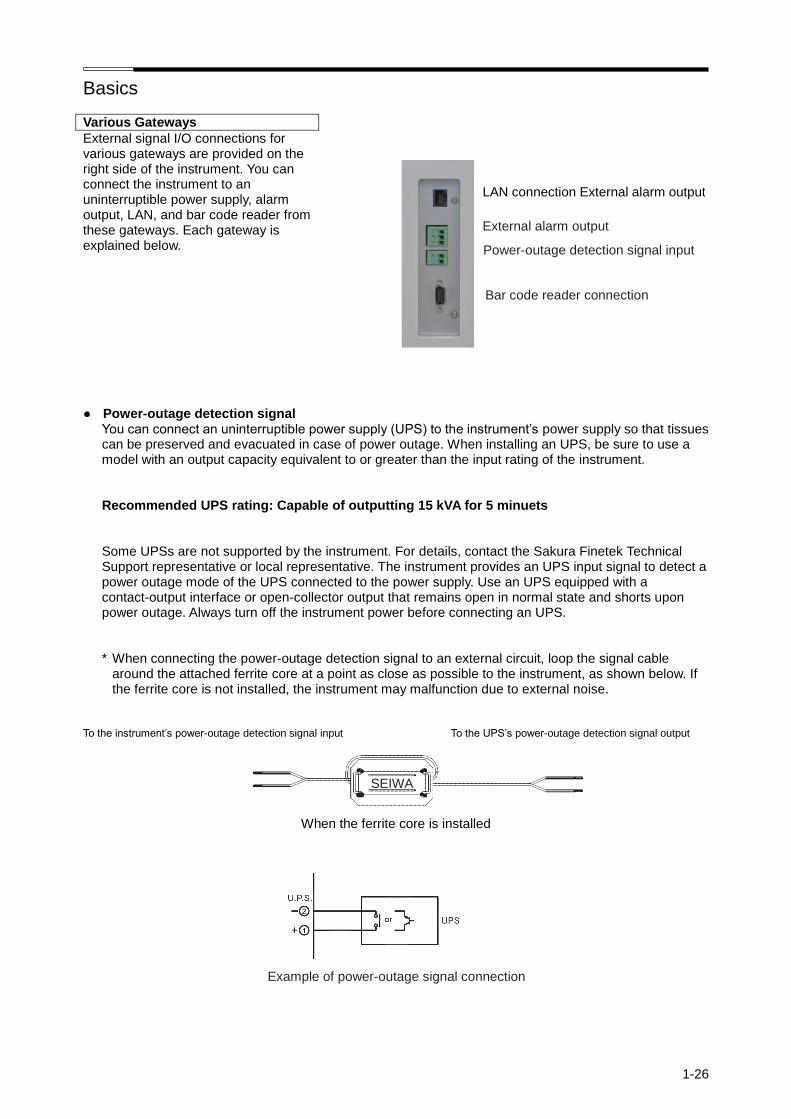
Basics
1-26
Various Gateways
External signal I/O connections for various gateways are provided on the right side of the instrument. You can connect the instrument to an uninterruptible power supply, alarm output, LAN, and bar code reader from these gateways. Each gateway is explained below.
● Power-outage detection signal
You can connect an uninterruptible power supply (UPS) to the instrument’s power supply so that tissues can be preserved and evacuated in case of power outage. When installing an UPS, be sure to use a model with an output capacity equivalent to or greater than the input rating of the instrument.
Recommended UPS rating: Capable of outputting 15 kVA for 5 minuets
Some UPSs are not supported by the instrument. For details, contact the Sakura Finetek Technical Support representative or local representative. The instrument provides an UPS input signal to detect a power outage mode of the UPS connected to the power supply. Use an UPS equipped with a contact-output interface or open-collector output that remains open in normal state and shorts upon power outage. Always turn off the instrument power before connecting an UPS.
* When connecting the power-outage detection signal to an external circuit, loop the signal cable around the attached ferrite core at a point as close as possible to the instrument, as shown below. If the ferrite core is not installed, the instrument may malfunction due to external noise.
To the instrument’s power-outage detection signal input To the UPS’s power-outage detection signal output
When the ferrite core is installed
Example of power-outage signal connection
SEIWA
LAN connection External alarm output
External alarm output
Bar code reader connection
Power-outage detection signal input
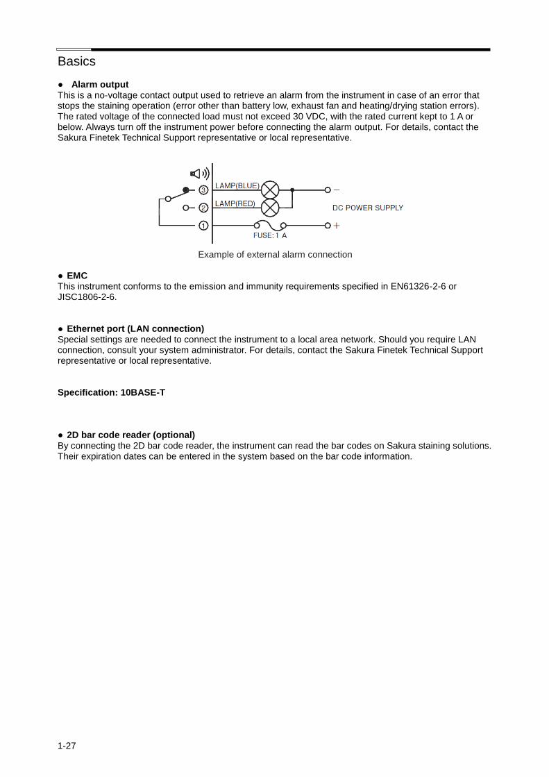
Basics
1-27
● Alarm output This is a no-voltage contact output used to retrieve an alarm from the instrument in case of an error that stops the staining operation (error other than battery low, exhaust fan and heating/drying station errors). The rated voltage of the connected load must not exceed 30 VDC, with the rated current kept to 1 A or below. Always turn off the instrument power before connecting the alarm output. For details, contact the Sakura Finetek Technical Support representative or local representative.
Example of external alarm connection ● EMC This instrument conforms to the emission and immunity requirements specified in EN61326-2-6 or JISC1806-2-6. ● Ethernet port (LAN connection) Special settings are needed to connect the instrument to a local area network. Should you require LAN connection, consult your system administrator. For details, contact the Sakura Finetek Technical Support representative or local representative. Specification: 10BASE-T ● 2D bar code reader (optional) By connecting the 2D bar code reader, the instrument can read the bar codes on Sakura staining solutions. Their expiration dates can be entered in the system based on the bar code information.

Basics
1-28
Relationship of Solution Configurations and Station Numbers
This section explains the relationship of solution configurations and station numbers shown on the screen. The link station is available only when the instrument is connected to an automated coverslipper. It cannot be used if an automated coverslipper is not connected. ● Arrangement of small solution stations The small solution stations can be arranged "without special solution stations" or "with special solution stations." In both cases, the solution configurations and number of stations are the same. However, the number of stations and station numbers vary depending on whether some stations are used as wash stations or solution stations.
Row 4 Station 1 Station 3 Station 5
Station 7 Station 8 Station 9 Station 10 Station 13
Station 2 Station 4 Station 6 Station 14
Row 3 Station 15 Station 17 Station 19 Station 21 Station 23 Station 25 Station 27 Station 29
Station 16 Station 18 Station 20 Station 22 Station 24 Station 26 Station 28 Station 30
Row 2 Station 31 Station 33 Station 35 Station 37 Station 39 Station 41 Station 43 Station 45
Station 32 Station 34 Station 36 Station 38 Station 40 Station 42 Station 44 Station 46
Frontmost row Station 53 Station 47 Station 48 Station 49 Station 50 Station 51 Station 52
Figure Arrangement with/without Special Solution Stations
Fixed station numbers are assigned to the start stations (S1 to S3), end stations (linked) (E1-1 to E1-5), end stations (not linked) (E2-1 to E2-5), wash stations (W1 to W4), drying stations (D1A, D1B, D2A, D2B), heating stations (H1, H2) and link station (LINK). The tables below specify the identification number of each station attribute and the corresponding station number.
* S2 and S3 can also be set as solution stations.
End station (linked) E1-1 E1-2 E1-3 E1-4 E1-5 PE station Without special solution stations
Station 47 Station 48 Station 49 Station 50 Station 51 The rightmost end station is selected as the PE station With special solution stations
* E1-2 to E1-5 can also be set as solution stations.
End station (not linked) E2-1 E2-2 E2-3 E2-4 E2-5
Without special solution stations Station 47 Station 48 Station 49 Station 50 Station 51
With special solution stations
* E2-2 to E2-5 can also be set as solution stations.
Link station LINK Wash station W1 W2 W3 W4
Without special solution stations Station 53
Without special solution stations Station 4 Station 5 Station 6 Station 7
With special solution stations With special solution stations
* W1 to W4 can also be set as solution stations.
Drying station D1A D1B D2A D2B Heating station H1 H2
Without special solution stations Station 13 Station 14 Station 29 Station 30
Without special solution stations Station 45 Station 46
With special solution stations With special solution stations
* Available with the DRS-Prisma-J0S only.
Special solution station SP1 SP2 SP3 SP4 SP5 SP6 SP7 SP8
Without special solution stations − - - - - - - - With special solution stations Station
21 Station
22 Station
23 Station
24 Station
25 Station
26 Station
27 Station
28
Start station S1 S2 S3
Without special solution stations Station 52 Station 51 Station 50
With special solution stations
* The link station can be set only when the instrument is connected to an automated coverslipper.

Basics
1-29
● Arrangement of standard solution stations (with drying stations) In the standard mode, the arrangement and number of stations vary depending on whether the solution stations are arranged "without special solution stations" or "with special solution stations."
Row 4 Station 1 Station 2 Station 3 Station 4 Station 5 Station 6 Station 7 Station 8
Row 3 Station 9 Station 10 Station 11 Station 12 Station 13 Station 14 Station 15 Station 16
Row 2 Station 17 Station 18 Station 19 Station 20 Station 21 Station 22 Station 23 Station 24
Frontmost row Station 31 Station 25 Station 26 Station 27 Station 28 Station 29 Station 30
Figure Arrangement without Special Solution Stations
Row 4 Station 1 Station 2 Station 3 Station 4 Station 5 Station 6 Station 7 Station 8
Row 3 Station 9 Station 10 Station 11 Station 12 Station 14 Station 16 Station 18 Station 20
Station 13 Station 15 Station 17 Station 19
Row 2 Station 21 Station 22 Station 23 Station 24 Station 25 Station 26 Station 27 Station 28
Frontmost row Station 35 Station 29 Station 30 Station 31 Station 32 Station 33 Station 34
Figure Arrangement with Special Solution Stations
Fixed station numbers are assigned to the start stations (S1 to S3), end stations (linked), (E1-1 to E1-5), end stations (not linked) (E2-1 to E2-5), wash stations (W1 to W4), drying stations (D1, D2) and link station (LINK). The tables below specify the identification number of each station attribute and the corresponding station number. The rightmost end station is selected as the PE station.
Start station S1 S2 S3 End station E1-1 E1-2 E1-3 E1-4 E1-5
Without special solution stations Station 30 Station 29 Station 28 Without special solution stations Station 25 Station 26 Station 27 Station 28 Station 29
With special solution stations Station 34 Station 33 Station 32 With special solution stations Station 29 Station 30 Station 31 Station 32 Station 33
* S2 and S3 can also be set as solution stations. * E1-2 to E1-5 can also be set as solution stations.
End station (not linked) E2-1 E2-2 E2-3 E2-4 E2-5
Without special solution stations Station 25 Station 26 Station 27 Station 28 Station 29
With special solution stations Station 29 Station 30 Station 31 Station 32 Station 33
* E2-2 to E2-5 can also be set as solution stations.
Link station LINK Wash station W1 W2 W3 W4
Without special solution stations Station 31 Without special solution stations Station 7 Station 6 Station 5 Station 4
With special solution stations Station 35 With special solution stations Station 7 Station 6 Station 5 Station 4
Drying station D1 D2
Without special solution stations Station 8 Station 16
With special solution stations Station 8 Station 20
* When a drying station unit is installed.
Special solution station SP1 SP2 SP3 SP4 SP5 SP6 SP7 SP8
Without special solution stations - - - - - - - -
With special solution stations Station 12 Station 13 Station 14 Station 15 Station 16 Station 17 Station 18 Station 19
* The link station can be set only when the instrument is connected to an automated coverslipper.
* W1 to W4 can also be set as solution stations.
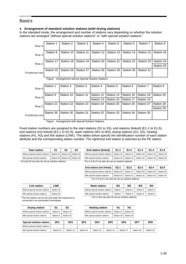
Basics
1-30
● Arrangement of standard solution stations (with drying stations) In the standard mode, the arrangement and number of stations vary depending on whether the solution stations are arranged "without special solution stations" or "with special solution stations."
Row 4 Station 1 Station 2 Station 3 Station 4 Station 5 Station 6 Station 7 Station 8
Row 3 Station 9 Station 10 Station 11 Station 12 Station 13 Station 14 Station 15 Station 16
Row 2 Station 17 Station 18 Station 19 Station 20 Station 21 Station 22 Station 23 Station 24
Station 25
Frontmost row Station 32 Station 26 Station 27 Station 28 Station 29 Station 30 Station 31
Figure Arrangement without Special Solution Stations
Row 4 Station 1 Station 2 Station 3 Station 4 Station 5 Station 6 Station 7 Station 8
Row 3 Station 9 Station 10 Station 11 Station 12 Station 14 Station 16 Station 18 Station 20
Station 13 Station 15 Station 17 Station 19
Row 2 Station 21 Station 22 Station 23 Station 24 Station 25 Station 26 Station 27 Station 28
Station 29
Frontmost row Station 36 Station 30 Station 31 Station 32 Station 33 Station 34 Station 35
Figure Arrangement with Special Solution Stations
Fixed station numbers are assigned to the start stations (S1 to S3), end stations (linked) (E1-1 to E1-5), end stations (not linked) (E2-1 to E2-5), wash stations (W1 to W4), drying stations (D1, D2), heating stations (H1, H2) and link station (LINK). The tables below specify the identification number of each station attribute and the corresponding station number. The rightmost end station is selected as the PE station.
Start station S1 S2 S3 End station (linked) E1-1 E1-2 E1-3 E1-4 E1-5
Without special solution stations Station 31 Station 30 Station 29 Without special solution stations Station 26 Station 27 Station 28 Station 29 Station 30
With special solution stations Station 35 Station 34 Station 33 With special solution stations Station 30 Station 31 Station 32 Station 33 Station 34
* S2 and S3 can also be set as solution stations. * E1-2 to E1-5 can also be set as solution stations.
End station (not linked) E2-1 E2-2 E2-3 E2-4 E2-5
Without special solution stations Station 26 Station 27 Station 28 Station 29 Station 30
With special solution stations Station 30 Station 31 Station 32 Station 33 Station 34
* E2-2 to E2-5 can also be set as solution stations.
Link station LINK Wash station W1 W2 W3 W4
Without special solution stations Station 32 Without special solution stations Station 7 Station 6 Station 5 Station 4
With special solution stations Station 36 With special solution stations Station 7 Station 6 Station 5 Station 4
* W1 to W4 can also be set as solution stations.
Drying station D1 D2 Heating station H1 H2
Without special solution stations Station 8 Station 16 Without special solution stations Station 24 Station 25
With special solution stations Station 8 Station 20 With special solution stations Station 28 Station 29
Special solution station SP1 SP2 SP3 SP4 SP5 SP6 SP7 SP8
Without special solution stations - - - - - - - -
With special solution stations Station 12 Station 13 Station 14 Station 15 Station 16 Station 17 Station 18 Station 19
* The link station can be set only when the instrument is connected to an automated coverslipper.
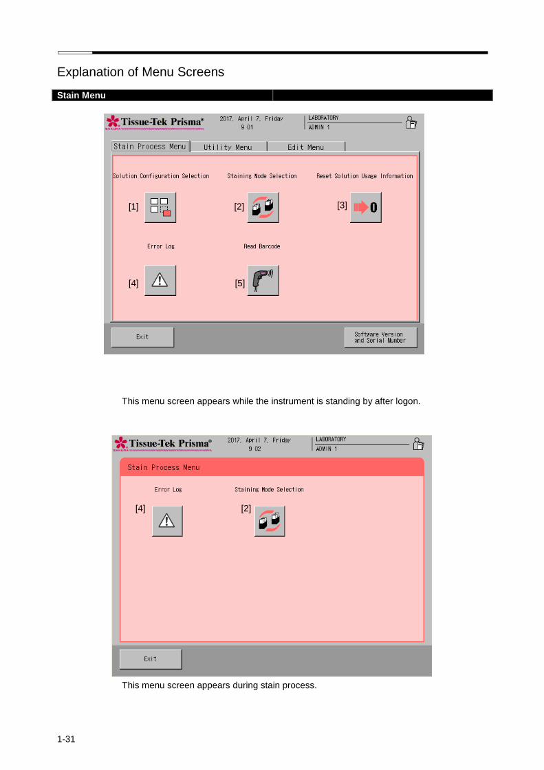
1-31
Explanation of Menu Screens
Stain Menu
This menu screen appears while the instrument is standing by after logon.
This menu screen appears during stain process.
[4] [2]
[1] [2] [3]
[4] [5]
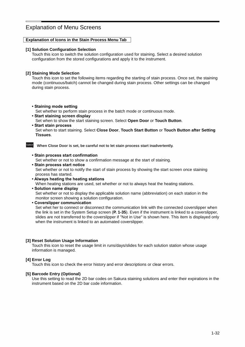
Explanation of Menu Screens
1-32
Explanation of Icons in the Stain Process Menu Tab
[1] Solution Configuration Selection
Touch this icon to switch the solution configuration used for staining. Select a desired solution configuration from the stored configurations and apply it to the instrument.
[2] Staining Mode Selection
Touch this icon to set the following items regarding the starting of stain process. Once set, the staining mode (continuous/batch) cannot be changed during stain process. Other settings can be changed during stain process.
• Staining mode setting Set whether to perform stain process in the batch mode or continuous mode.
• Start staining screen display Set when to show the start staining screen. Select Open Door or Touch Button.
• Start stain process Set when to start staining. Select Close Door, Touch Start Button or Touch Button after Setting Tissues.
When Close Door is set, be careful not to let stain process start inadvertently.
• Stain process start confirmation
Set whether or not to show a confirmation message at the start of staining. • Stain process start notice
Set whether or not to notify the start of stain process by showing the start screen once staining process has started.
• Always heating the heating stations When heating stations are used, set whether or not to always heat the heating stations.
• Solution name display Set whether or not to display the applicable solution name (abbreviation) on each station in the monitor screen showing a solution configuration.
• Coverslipper communication Set whet her to connect or disconnect the communication link with the connected coverslipper when the link is set in the System Setup screen (P. 1-35). Even if the instrument is linked to a coverslipper, slides are not transferred to the coverslipper if "Not in Use" is shown here. This item is displayed only when the instrument is linked to an automated coverslipper.
[3] Reset Solution Usage Information Touch this icon to reset the usage limit in runs/days/slides for each solution station whose usage information is managed.
[4] Error Log Touch this icon to check the error history and error descriptions or clear errors.
[5] Barcode Entry (Optional) Use this setting to read the 2D bar codes on Sakura staining solutions and enter their expirations in the instrument based on the 2D bar code information.
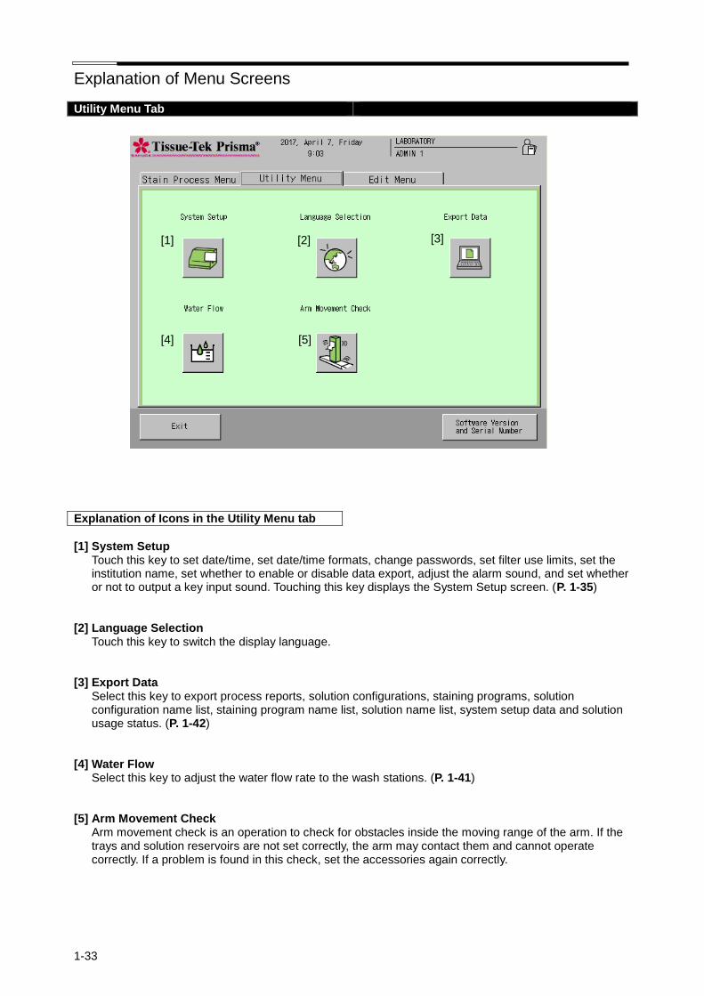
Explanation of Menu Screens
1-33
Utility Menu Tab
Explanation of Icons in the Utility Menu tab
[1] System Setup
Touch this key to set date/time, set date/time formats, change passwords, set filter use limits, set the institution name, set whether to enable or disable data export, adjust the alarm sound, and set whether or not to output a key input sound. Touching this key displays the System Setup screen. (P. 1-35)
[2] Language Selection
Touch this key to switch the display language. [3] Export Data
Select this key to export process reports, solution configurations, staining programs, solution configuration name list, staining program name list, solution name list, system setup data and solution usage status. (P. 1-42)
[4] Water Flow
Select this key to adjust the water flow rate to the wash stations. (P. 1-41) [5] Arm Movement Check
Arm movement check is an operation to check for obstacles inside the moving range of the arm. If the trays and solution reservoirs are not set correctly, the arm may contact them and cannot operate correctly. If a problem is found in this check, set the accessories again correctly.
[1] [2] [3]
[4] [5]
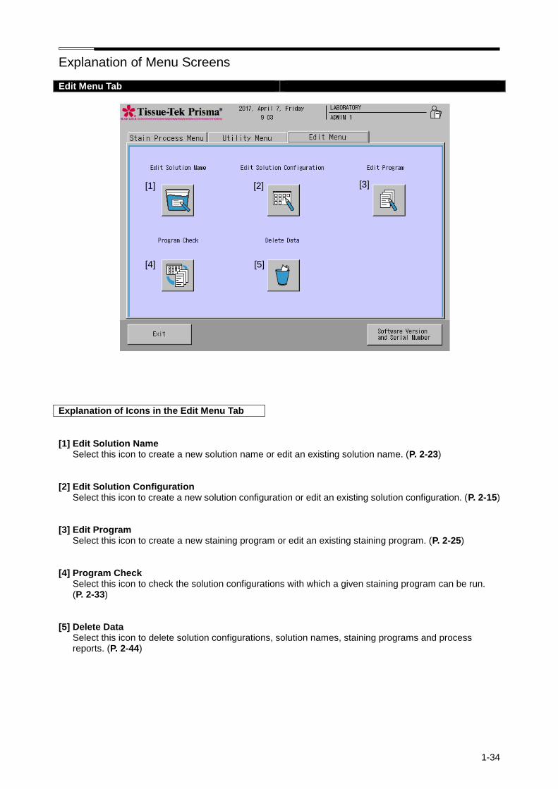
Explanation of Menu Screens
1-34
Edit Menu Tab
Explanation of Icons in the Edit Menu Tab
[1] Edit Solution Name
Select this icon to create a new solution name or edit an existing solution name. (P. 2-23) [2] Edit Solution Configuration
Select this icon to create a new solution configuration or edit an existing solution configuration. (P. 2-15) [3] Edit Program
Select this icon to create a new staining program or edit an existing staining program. (P. 2-25) [4] Program Check
Select this icon to check the solution configurations with which a given staining program can be run. (P. 2-33)
[5] Delete Data
Select this icon to delete solution configurations, solution names, staining programs and process reports. (P. 2-44)
[1] [2] [3]
[4] [5]

1-35
System Setup
System Setup
In the System Setup screen accessible from the Utility Menu tab, you can define the basic settings needed to use the instrument.
[1]
[2]
[3]
[4]
[5]
[6]
[7]
[8]
[9]
[10]
[11]
[12]

System Setup
1-36
[1] Date Format
This sets the format for the date display. Touching the option button toggles the display format in the sequence of "Year/Month/Day," "Month/Day/Year" and "Day/Month/Year."
[2] Time Format
This sets the format for the time display. Touching the option button switches the time format between "12 hour format" and "24 hour format."
[3] Key Sound
This selects whether to turn "ON" or "OFF" the sound output when a key is touched. [4] Alarm Tone and Volume
This sets the tone and volume for system alarms. Touching the button toggles label on the button "Loud and High," "Loud and Low," "Soft and High" and "Soft and Low."
[5] Station Colors
Touching the button toggles label on the button between "Each Solution Name" and "Each Station." [6] Export Data
This sets whether or not exporting data is possible and the destination path for data export. Touching the button toggles label on the button between "File" and "OFF."
[7] Coverslipper Link
This button is used to set whether or not to enable the Coverslipper link. This item is displayed only when the instrument is linked to an automated coverslipper.
[8] Coverslipper
If the Coverslipper link is installed, Coverslipper can be selected. [9] Date and Time
You can set date and time. (P. 1-37) [10] Password Input
You can manage user IDs and passwords. (P. 1-38) [11] Fume Filter Management
You can manage filter use limits. (P. 1-40) [12] Institution Name
You can set the name of the institution where the instrument is used. Touching the Institution Name key displays the simple keyboard. Enter the applicable institution name and then touch the Save key to save the name. An institution name can be entered using up to 20 characters. Touch the Caps Lock key to enter characters in uppercase. Touch the key again to enter characters in lowercase.

System Setup
1-37
Setting Date and Time
You can set date and time by touching Date and Time from the System Setup screen accessible from the Utility Menu tab.
Entering Year
Touching the Modify button on the right of "Year" displays the numeric keypad. Enter the current year using the numeric keypad. You can enter a year in the range of 2000 to 2099.
Entering Month
Every time the ▲ or ▼ key is touched on the right of "Month," the selection changes to the next month (▲) or previous month (▼).
Entering Day
Select a desired day by touching the corresponding number in the calendar.
Entering Hours and Minutes
You can enter hours and minutes using the numeric keypad displayed by touching the Modify button below each item. Follow the time format selected by touching option button of "Time Format" (12 hour format/24 hour format) from the System Setup screen.
am/pm
You can select am or pm only when the 12 hour format is currently selected. After all items have been entered, touching the Save key to apply the settings.

System Setup
1-38
Setting User IDs, Passwords and Accessible Functions
You can set user IDs and passwords as well as the functions accessible by each user by selecting Password Input from the System Setup screen accessible from the Utility Menu tab. To set each item, select the applicable user and perform the corresponding operation explained below.
Setting an ID
You can change the existing ID of a user. Touching the User’s ID key displays the simple keyboard.
Enter a new user ID, and then touch the Save key to save the ID. A user ID can be entered using up to 20 characters. Touch the Caps Lock key to enter characters in uppercase. Touch the key again to enter characters in lowercase.
Setting a Password
You can change a password only when you have logged on as an Administrator. Select the user whose password you want to set, touch the Password Setup key, and then enter a new password consisting of one to six digits on the numeric keypad. The entered password is shown in asterisks (*) in the password field. After the password has been entered, touch the Enter key. When the screen prompts you to enter the password again for confirmation, enter the same password and touch the Enter key again to save the password. Up to four "Administrator" passwords and 20 "User" passwords can be saved. The factory settings are shown below.
Level Factory-set IDs Factory-set passwords
Administrator [ADMIN 1] ~ [ADMIN 4] [100000] ~ [400000]
User [OPERATOR 1] ~ [OPERATOR 20] [000001] ~ [000020]
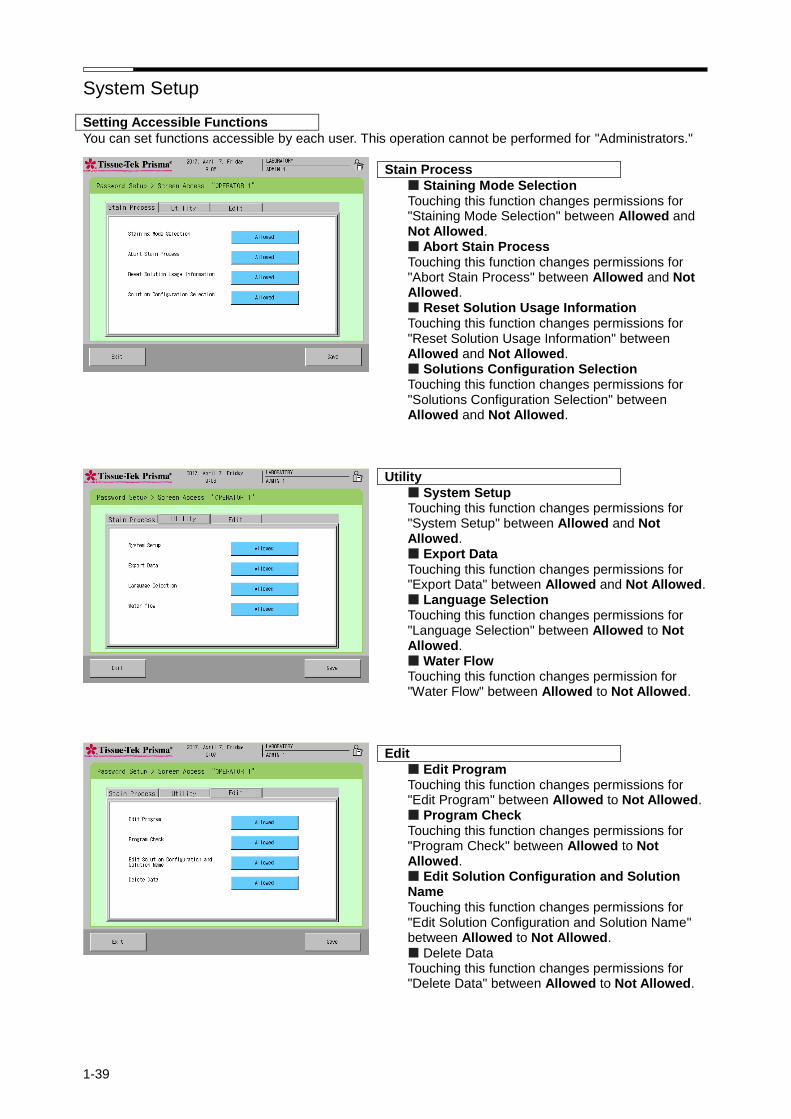
System Setup
1-39
Setting Accessible Functions
You can set functions accessible by each user. This operation cannot be performed for "Administrators."
Stain Process
Staining Mode Selection Touching this function changes permissions for "Staining Mode Selection" between Allowed and Not Allowed. Abort Stain Process Touching this function changes permissions for "Abort Stain Process" between Allowed and Not Allowed. Reset Solution Usage Information Touching this function changes permissions for "Reset Solution Usage Information" between Allowed and Not Allowed. Solutions Configuration Selection Touching this function changes permissions for "Solutions Configuration Selection" between Allowed and Not Allowed.
Utility
System Setup Touching this function changes permissions for "System Setup" between Allowed and Not Allowed. Export Data Touching this function changes permissions for "Export Data" between Allowed and Not Allowed. Language Selection Touching this function changes permissions for "Language Selection" between Allowed to Not Allowed. Water Flow Touching this function changes permission for "Water Flow" between Allowed to Not Allowed.
Edit
Edit Program Touching this function changes permissions for "Edit Program" between Allowed to Not Allowed. Program Check Touching this function changes permissions for "Program Check" between Allowed to Not Allowed. Edit Solution Configuration and Solution Name Touching this function changes permissions for "Edit Solution Configuration and Solution Name" between Allowed to Not Allowed. Delete Data Touching this function changes permissions for "Delete Data" between Allowed to Not Allowed.

System Setup
1-40
Fume Filter Management
You can set items relating to fume filter management by selecting Fume Filter Management in the System Setup screen accessible from the Utility Menu tab.
Whether or Not to Use Fume Filter Management
You can set whether or not to manage the use of fume filters. Touch the button to change between "In Use" and "Not in Use."
Setting a Time Limit
Selecting "In Use" enables to touch the Set Time Limit key. When the Set Time Limit key is touched, you can set a time limit for fume filters. Touching this key displays the numeric keypad, so enter a desired time limit. To reset the entered time limit, touch the Clear key. A time limit can be set in the range of 1 to 999 hours in units of "hours." The default is "240" hours. After you have entered the time limit, touch the Enter key to save the entry. To maintain a clean work environment, it is recommended that the activated carbon filters (each set consists of two filters) be replaced at least once every two weeks.
Resetting the Actual Time
Touch the Reset Actual Time button to initialize the present counter value of filter usage time. Touching the button resets the actual time currently stored. When all items have been set, touch the Exit key to return to the System Setup screen.

System Setup
1-41
Adjusting the Water Flow
You can change the run-up time for water supply to the wash stations by selecting Water Flow from the Utility Menu tab. • Water supply run-up time --- The time at which water supply to the wash stations is started during stain
process, prior to the transfer of tissues into the wash stations. Change the setting whenever necessary before the start of staining, after changing the solution configuration or staining program, and so on. The water supply run-up time must be changed after the wash solution configuration has been changed. The water flow can be adjusted with the hood open. 1. Confirm that water has been drained from all wash stations. 2. Open the water supply handle. 3. Touch the Start key and wait for water to overflow from the wash stations. 4. Once water starts to overflow from the wash stations, touch the Stop key. Adjust the water supply
handle so that water will overflow within 20 to 30 seconds. 5. The water supply run-up time you have just set is displayed and the save screen appears. Touch Save if
you want to use this run-up time. Touching Exit returns to the Water Flow screen.
Water supply handle
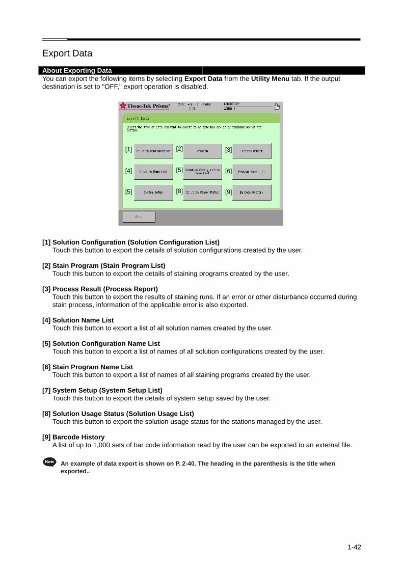
1-42
Export Data
About Exporting Data
You can export the following items by selecting Export Data from the Utility Menu tab. If the output destination is set to "OFF," export operation is disabled. [1] Solution Configuration (Solution Configuration List)
Touch this button to export the details of solution configurations created by the user. [2] Stain Program (Stain Program List)
Touch this button to export the details of staining programs created by the user. [3] Process Result (Process Report)
Touch this button to export the results of staining runs. If an error or other disturbance occurred during stain process, information of the applicable error is also exported.
[4] Solution Name List
Touch this button to export a list of all solution names created by the user. [5] Solution Configuration Name List
Touch this button to export a list of names of all solution configurations created by the user. [6] Stain Program Name List
Touch this button to export a list of names of all staining programs created by the user. [7] System Setup (System Setup List)
Touch this button to export the details of system setup saved by the user. [8] Solution Usage Status (Solution Usage List)
Touch this button to export the solution usage status for the stations managed by the user. [9] Barcode History
A list of up to 1,000 sets of bar code information read by the user can be exported to an external file.
An example of data export is shown on P. 2-40. The heading in the parenthesis is the title when
exported..
[1]
[4]
[5]
[2]
[5]
[8]
[3]
[6]
[9]

1-43
Names of Files Exported to a CF Card
If the export destination is set to File, each set of output data is saved to a CF card as a file. The files of each exported item are named in the applicable format shown below.
Exported item File name
Solution configuration CL*****.txt
Staining program PL*****.txt
Process report REP*****.txt
Solution name SNL*****.txt
Solution configuration name CNL*****.txt
Staining program name PNL*****.txt
System setup ISL*****.txt
Solution usage status SUL*****.txt
Bar code history BCH*****.txt
Chapter 2 Operating Procedure
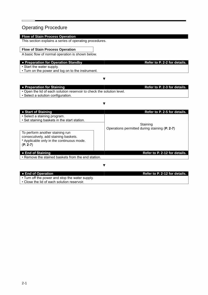
2-1
Operating Procedure
Flow of Stain Process Operation
This section explains a series of operating procedures.
Flow of Stain Process Operation
A basic flow of normal operation is shown below.
● Preparation for Operation Standby Refer to P. 2-2 for details.
• Start the water supply. • Turn on the power and log on to the instrument.
▼
● Preparation for Staining Refer to P. 2-3 for details.
• Open the lid of each solution reservoir to check the solution level. • Select a solution configuration.
▼
● Start of Staining Refer to P. 2-5 for details.
• Select a staining program. • Set staining baskets in the start station.
Staining Operations permitted during staining (P. 2-7)
To perform another staining run consecutively, add staining baskets. * Applicable only in the continuous mode.
(P. 2-7)
● End of Staining Refer to P. 2-12 for details.
• Remove the stained baskets from the end station.
▼
● End of Operation Refer to P. 2-12 for details.
• Turn off the power and stop the water supply. • Close the lid of each solution reservoir.
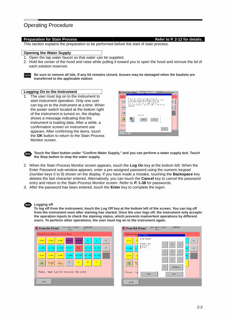
Operating Procedure
2-2
Preparation for Stain Process Refer to P. 2-12 for details.
This section explains the preparation to be performed before the start of stain process.
Opening the Water Supply
1. Open the tap water faucet so that water can be supplied. 2. Hold the center of the hood and raise while pulling it toward you to open the hood and remove the lid of
each solution reservoir. Be sure to remove all lids. If any lid remains closed, tissues may be damaged when the baskets are
transferred to the applicable station.
Logging On to the Instrument
1. The user must log on to the instrument to start instrument operation. Only one user can log on to the instrument at a time. When the power switch located at the bottom right of the instrument is turned on, the display shows a message indicating that the instrument is loading data. After a while, a confirmation screen on instrument use appears. After confirming the items, touch the OK button to return to the Stain Process Monitor screen.
Touch the Start button under "Confirm Water Supply," and you can perform a water supply test. Touch
the Stop button to stop the water supply.
2. When the Stain Process Monitor screen appears, touch the Log On key at the bottom left. When the
Enter Password sub-window appears, enter a pre-assigned password using the numeric keypad (number keys 0 to 9) shown on the display. If you have made a mistake, touching the Backspace key deletes the last character entered. Alternatively, you can touch the Cancel key to cancel the password entry and return to the Stain Process Monitor screen. Refer to P. 1-38 for passwords.
3. After the password has been entered, touch the Enter key to complete the logon. Logging off
To log off from the instrument, touch the Log Off key at the bottom left of the screen. You can log off from the instrument even after staining has started. Once the user logs off, the instrument only accepts the operation inputs to check the staining status, which prevents inadvertent operations by different users. To perform other operations, the user must log on to the instrument again.

Operating Procedure
2-3
Selecting and Saving a Solution Configuration and Setting Solutions
The instrument can store multiple solution configurations and staining programs. Accordingly, you must select a solution configuration appropriate for the staining program you want to run and display the selected configuration on the monitor screen before starting the program. This section explains how to select and save a solution configuration that will be displayed on the monitor screen.
1. Touch the Menu key shown at the bottom right of the Stain Process Monitor screen. 2. Select Stain Process Menu from the Stain Process Menu, Utility Menu or Edit Menu tab, and then touch
the Solution Configuration Selection key. 3. Select and touch a desired solution configuration name under Solution Configuration List, and then
touch the Select key. For creating a new station configuration or editing an existing station configuration, refer to "Setting a Solution Configuration" (P. 2-15).
"Selecting a Solution Configuration" If any of the following conditions applies to a solution station for
which a solution management option has been set, the solution management information will not be transferred. • The station position where solution management is performed changes when the solution
configuration changes. • The solution at the station position where solution management is performed changes to a different
solution when the solution configuration changes. • The management method for the station where solution management is performed changes when the
solution configuration changes. If the solution used, station position (station number) and management method do not change after the solution configuration is changed, the solution management information will be transferred.
Touch the Check Program key to check the staining programs that can be operated with the solution configuration you have selected. To check a given solution configuration, select the applicable solution configuration and touch the View key to display the Solution Configuration View screen showing the applicable station arrangement. You can also check the reservoir arrangement of the next configuration by touching the Change View key at the bottom right. If the current solution configuration is appropriate, touch the Select key. To check other solution configuration, touch the Exit key and select a desired solution configuration again.

Operating Procedure
2-4
4. Touching the Select key displays the New Solution Configuration screen. If the new solution configuration you have selected requires changing the arm holder from the 3-position type to 1-position type, or from the 1-position type to 3-position type, the Change Arm Holder window appears with the message asking if the arm holder has been changed. Change the arm holder according to the message, and then touch Yes. Refer to P. 1-13 for details on how to change the arm holder.
5. Open the hood and set solutions according to the screen display. First, set solution reservoirs by paying attention to the different reservoir types; i.e., standard solution reservoir, small solution reservoir and special stain solution reservoir.
6. Next, fill solutions into the reservoirs. Solutions should be filled into the solution reservoirs beforehand on a flat, stable surface, or directly into the reservoirs already set in the instrument. If solutions are filled outside the instrument, transport the filled reservoirs into the instrument using special solution trays to facilitate the operation.
7. After all solutions have been set, close the hood and touch the Exit key to save the selected solution configuration.
To perform other operation, you can return to the Stain Process Menu screen by touching the Cancel key.
Setting Slides into Baskets
This section explains how to set slides into baskets. 1. Prepare slides to be stained. Check the solution configuration and prepare baskets (20-slide or 10-slide
baskets) together with appropriate basket adapters. 2. Attach a basket adapter to each basket by aligning the "UP SIDE" mark on top of the adapter with the
"UP SIDE" mark on one side of the basket. After confirming that both "UP SIDE" marks are facing the same direction, tilt the basket adapter along the groove.
3. Next, store the slide into the basket one by one. Set the slides in the correct orientation so that their tissue side aligns with the "UP SIDE" marks. When all slides have been set, return the tilted basket adapter to the original position.
Do not use a deteriorated, worn, damaged or deformed basket/basket adapter, as it may cause problems.
Replace any such basket/basket adapter with a new one. Store the slides evenly in the basket.
If the slides are stored unevenly, basket movements are affected during the staining operation.
Particularly when there are fewer slides, be careful not to let the basket tilt when storing the slides.
Tissue side "UP SIDE" mark "UP SIDE" mark
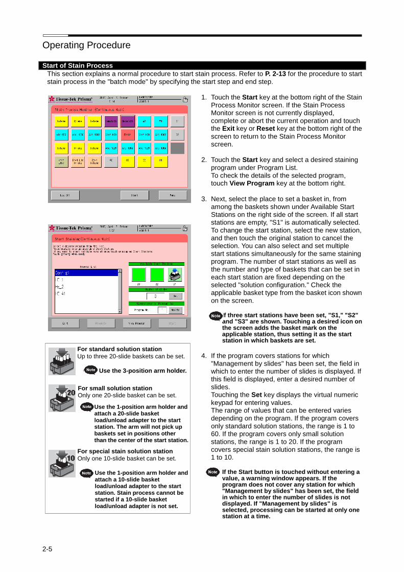
Operating Procedure
2-5
Start of Stain Process
This section explains a normal procedure to start stain process. Refer to P. 2-13 for the procedure to start stain process in the "batch mode" by specifying the start step and end step.
1. Touch the Start key at the bottom right of the Stain Process Monitor screen. If the Stain Process Monitor screen is not currently displayed, complete or abort the current operation and touch the Exit key or Reset key at the bottom right of the screen to return to the Stain Process Monitor screen.
2. Touch the Start key and select a desired staining
program under Program List. To check the details of the selected program, touch View Program key at the bottom right.
3. Next, select the place to set a basket in, from
among the baskets shown under Available Start Stations on the right side of the screen. If all start stations are empty, "S1" is automatically selected. To change the start station, select the new station, and then touch the original station to cancel the selection. You can also select and set multiple start stations simultaneously for the same staining program. The number of start stations as well as the number and type of baskets that can be set in each start station are fixed depending on the selected "solution configuration." Check the applicable basket type from the basket icon shown on the screen.
If three start stations have been set, "S1," "S2"
and "S3" are shown. Touching a desired icon on the screen adds the basket mark on the applicable station, thus setting it as the start station in which baskets are set.
4. If the program covers stations for which
"Management by slides" has been set, the field in which to enter the number of slides is displayed. If this field is displayed, enter a desired number of slides. Touching the Set key displays the virtual numeric keypad for entering values. The range of values that can be entered varies depending on the program. If the program covers only standard solution stations, the range is 1 to 60. If the program covers only small solution stations, the range is 1 to 20. If the program covers special stain solution stations, the range is 1 to 10.
If the Start button is touched without entering a
value, a warning window appears. If the program does not cover any station for which "Management by slides" has been set, the field in which to enter the number of slides is not displayed. If "Management by slides" is selected, processing can be started at only one station at a time.
For standard solution station
Up to three 20-slide baskets can be set.
Use the 3-position arm holder.
For small solution station Only one 20-slide basket can be set.
Use the 1-position arm holder and attach a 20-slide basket load/unload adapter to the start station. The arm will not pick up baskets set in positions other than the center of the start station.
For special stain solution station
Only one 10-slide basket can be set.
Use the 1-position arm holder and attach a 10-slide basket load/unload adapter to the start station. Stain process cannot be started if a 10-slide basket load/unload adapter is not set.
Operating Procedure
2-6
5. Open the door at the bottom of the hood to set a basket into the start station. Push the top of the center of the door toward the back once opens the door toward you. When the door opens, draw out the reservoir in the start station and set by paying attention to the orientation of the basket in which slides have been set. Set the basket so that the "UP SIDE" mark on top of the basket adapter faces right. Align the grooves in the top surface of the start station with the grooves provided at both ends of the top surface of the basket adapter. After setting the basket, push the start station reservoir into the instrument, close the door, and then push the door until a click sound is heard.
When setting a small solution reservoir or special stain solution reservoir, attach an applicable
adapter to the start station. If not, stain process cannot be performed correctly. Also confirm that the arm holder has only one tab. If a wrong arm holder is set, stain process cannot be performed correctly.
6. Touching the Start key at the bottom right of the screen displays a confirmation message. Select Start
to start staining. 7. Once staining starts, the Stain Process Monitor screen appears where you can check the current
processing. Refer to P. 2-7 for the operations permitted during stain process.
The starting procedure explained above is only one example. If the instrument has been set to start
staining upon closing of the door, you need not touch the Start key because closing the door automatically starts stain process. Refer to P. 1-32 for the settings relating to the starting procedure.
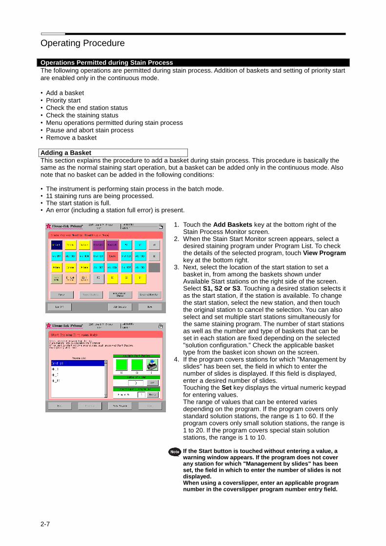
Operating Procedure
2-7
Operations Permitted during Stain Process
The following operations are permitted during stain process. Addition of baskets and setting of priority start are enabled only in the continuous mode.
• Add a basket • Priority start • Check the end station status • Check the staining status • Menu operations permitted during stain process • Pause and abort stain process • Remove a basket
Adding a Basket
This section explains the procedure to add a basket during stain process. This procedure is basically the same as the normal staining start operation, but a basket can be added only in the continuous mode. Also note that no basket can be added in the following conditions:
• The instrument is performing stain process in the batch mode. • 11 staining runs are being processed. • The start station is full. • An error (including a station full error) is present.
1. Touch the Add Baskets key at the bottom right of the
Stain Process Monitor screen. 2. When the Stain Start Monitor screen appears, select a
desired staining program under Program List. To check the details of the selected program, touch View Program key at the bottom right.
3. Next, select the location of the start station to set a basket in, from among the baskets shown under Available Start stations on the right side of the screen. Select S1, S2 or S3. Touching a desired station selects it as the start station, if the station is available. To change the start station, select the new station, and then touch the original station to cancel the selection. You can also select and set multiple start stations simultaneously for the same staining program. The number of start stations as well as the number and type of baskets that can be set in each station are fixed depending on the selected "solution configuration." Check the applicable basket type from the basket icon shown on the screen.
4. If the program covers stations for which "Management by slides" has been set, the field in which to enter the number of slides is displayed. If this field is displayed, enter a desired number of slides. Touching the Set key displays the virtual numeric keypad for entering values. The range of values that can be entered varies depending on the program. If the program covers only standard solution stations, the range is 1 to 60. If the program covers only small solution stations, the range is 1 to 20. If the program covers special stain solution stations, the range is 1 to 10.
If the Start button is touched without entering a value, a
warning window appears. If the program does not cover any station for which "Management by slides" has been set, the field in which to enter the number of slides is not displayed. When using a coverslipper, enter an applicable program number in the coverslipper program number entry field.
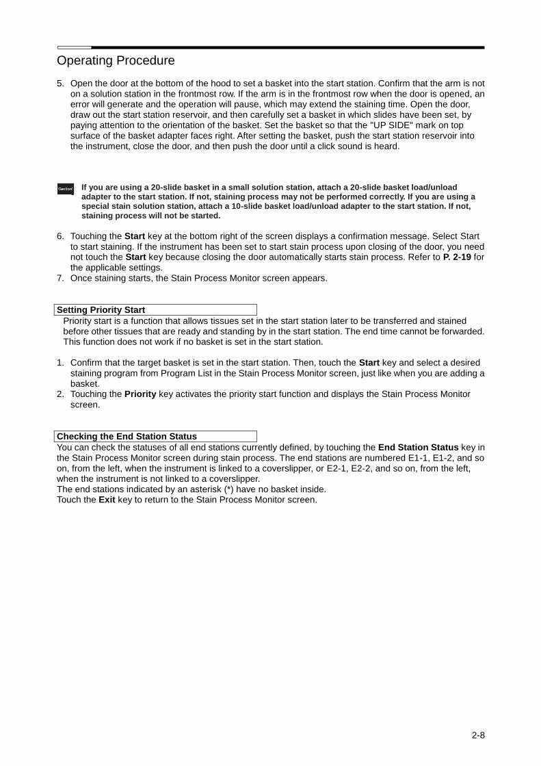
Operating Procedure
2-8
5. Open the door at the bottom of the hood to set a basket into the start station. Confirm that the arm is not on a solution station in the frontmost row. If the arm is in the frontmost row when the door is opened, an error will generate and the operation will pause, which may extend the staining time. Open the door, draw out the start station reservoir, and then carefully set a basket in which slides have been set, by paying attention to the orientation of the basket. Set the basket so that the "UP SIDE" mark on top surface of the basket adapter faces right. After setting the basket, push the start station reservoir into the instrument, close the door, and then push the door until a click sound is heard.
If you are using a 20-slide basket in a small solution station, attach a 20-slide basket load/unload adapter to the start station. If not, staining process may not be performed correctly. If you are using a special stain solution station, attach a 10-slide basket load/unload adapter to the start station. If not, staining process will not be started.
6. Touching the Start key at the bottom right of the screen displays a confirmation message. Select Start
to start staining. If the instrument has been set to start stain process upon closing of the door, you need not touch the Start key because closing the door automatically starts stain process. Refer to P. 2-19 for the applicable settings.
7. Once staining starts, the Stain Process Monitor screen appears.
Setting Priority Start
Priority start is a function that allows tissues set in the start station later to be transferred and stained before other tissues that are ready and standing by in the start station. The end time cannot be forwarded. This function does not work if no basket is set in the start station.
1. Confirm that the target basket is set in the start station. Then, touch the Start key and select a desired staining program from Program List in the Stain Process Monitor screen, just like when you are adding a basket.
2. Touching the Priority key activates the priority start function and displays the Stain Process Monitor screen.
Checking the End Station Status
You can check the statuses of all end stations currently defined, by touching the End Station Status key in the Stain Process Monitor screen during stain process. The end stations are numbered E1-1, E1-2, and so on, from the left, when the instrument is linked to a coverslipper, or E2-1, E2-2, and so on, from the left, when the instrument is not linked to a coverslipper. The end stations indicated by an asterisk (*) have no basket inside. Touch the Exit key to return to the Stain Process Monitor screen.
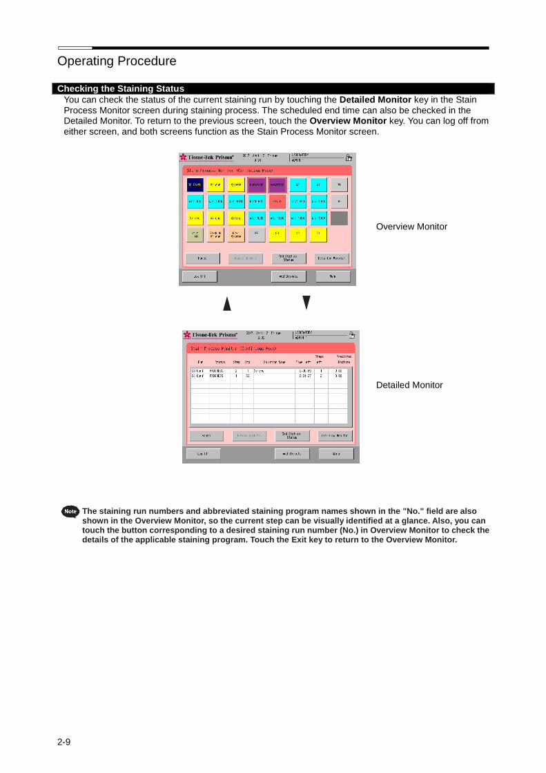
Operating Procedure
2-9
Checking the Staining Status
You can check the status of the current staining run by touching the Detailed Monitor key in the Stain Process Monitor screen during staining process. The scheduled end time can also be checked in the Detailed Monitor. To return to the previous screen, touch the Overview Monitor key. You can log off from either screen, and both screens function as the Stain Process Monitor screen. Overview Monitor Detailed Monitor
The staining run numbers and abbreviated staining program names shown in the "No." field are also shown in the Overview Monitor, so the current step can be visually identified at a glance. Also, you can touch the button corresponding to a desired staining run number (No.) in Overview Monitor to check the details of the applicable staining program. Touch the Exit key to return to the Overview Monitor.
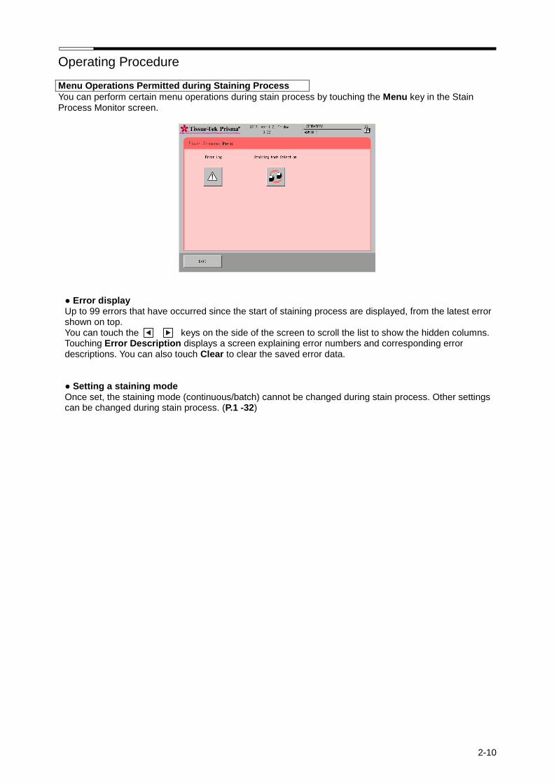
Operating Procedure
2-10
Menu Operations Permitted during Staining Process
You can perform certain menu operations during stain process by touching the Menu key in the Stain Process Monitor screen.
● Error display Up to 99 errors that have occurred since the start of staining process are displayed, from the latest error shown on top. You can touch the keys on the side of the screen to scroll the list to show the hidden columns. Touching Error Description displays a screen explaining error numbers and corresponding error descriptions. You can also touch Clear to clear the saved error data. ● Setting a staining mode Once set, the staining mode (continuous/batch) cannot be changed during stain process. Other settings can be changed during stain process. (P.1 -32)
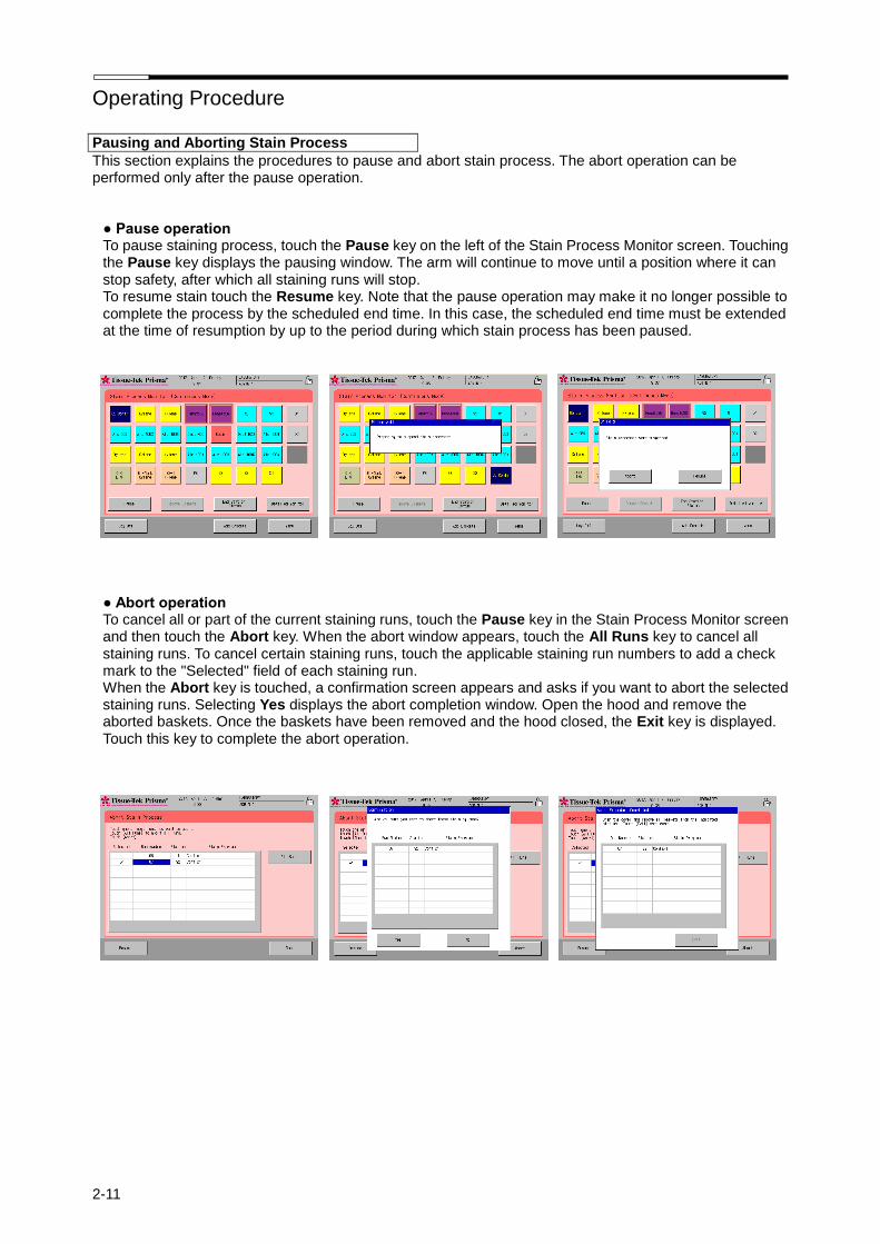
Operating Procedure
2-11
Pausing and Aborting Stain Process
This section explains the procedures to pause and abort stain process. The abort operation can be performed only after the pause operation.
● Pause operation To pause staining process, touch the Pause key on the left of the Stain Process Monitor screen. Touching the Pause key displays the pausing window. The arm will continue to move until a position where it can stop safety, after which all staining runs will stop. To resume stain touch the Resume key. Note that the pause operation may make it no longer possible to complete the process by the scheduled end time. In this case, the scheduled end time must be extended at the time of resumption by up to the period during which stain process has been paused. ● Abort operation To cancel all or part of the current staining runs, touch the Pause key in the Stain Process Monitor screen and then touch the Abort key. When the abort window appears, touch the All Runs key to cancel all staining runs. To cancel certain staining runs, touch the applicable staining run numbers to add a check mark to the "Selected" field of each staining run. When the Abort key is touched, a confirmation screen appears and asks if you want to abort the selected staining runs. Selecting Yes displays the abort completion window. Open the hood and remove the aborted baskets. Once the baskets have been removed and the hood closed, the Exit key is displayed. Touch this key to complete the abort operation.

Operating Procedure
2-12
Removing a Basket during Stain Process
The following operation is performed when removing a basket from the end station or PE station during stain process or after completion of stain process. It cannot be performed if the end station or PE station contains no basket.
1. Confirm that the arm is not on a solution station in the frontmost row, and then open the door and
remove the basket. 2. Once the basket has been removed and the door closed, the basket removal confirmation window
appears. Touch the Yes key in this window. If you have not yet removed the basket, touch the No key.
End of Stain Process
Stained baskets are stored in the specified end station or PE station. (If the instrument is linked to the Coverslipper, stained baskets are stored in the link station. If the link station is full, stained baskets are temporarily stored in the end station and wait there until they can be stored in the link station.)
Removing Stained Baskets
1. A window notifying the end of stain process appears and automatically disappears in around 15 seconds.
2. Confirm that the arm is not on a solution station in the frontmost row, and then open the door and remove the basket.
3. Once the basket has been removed and the door closed, the basket removal confirmation window appears. Touch the Yes key in this window. If you have not yet removed the basket, touch the No key.
After the door is opened, remove all stained baskets from the end station and PE station.
End of Operation
This section explains the procedure to complete the stain process and end the operation.
1. After all operations have completed, turn off the power switch located at the bottom right of the instrument, and then stop the water supply.
2. Close the lids on all solution reservoirs, and then close the hood. This completes the series of operations.

Operating Procedure
2-13
How to Start Stain Process by Specifying the Start and End Steps
You can start stain process by specifying the start and end steps only in the batch mode. If a desired step is specified as the start step, the staining program will start from the specified step. If a desired step is specified as the end step, staining process will end at the specified step and the baskets will be transferred to the end station specified in the applicable staining program.
The start and end steps only represent temporary changes in the start and end stations. The settings will become ineffective once the series of staining runs are completed or aborted. The start and end steps cannot be set on the stations shown in the table below. If the start step is set on a drying station, the drying station heater is turned on at the start of staining. If the start step is set on a heating station, the baskets are held in the start station until the heating station reaches the specified temperature.
Stations that cannot be set as the start step Stations that cannot be set as the end step
End stations, PE station Start stations, End stations, PE station
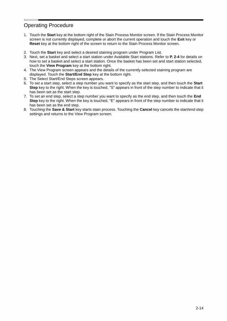
Operating Procedure
2-14
1. Touch the Start key at the bottom right of the Stain Process Monitor screen. If the Stain Process Monitor screen is not currently displayed, complete or abort the current operation and touch the Exit key or Reset key at the bottom right of the screen to return to the Stain Process Monitor screen.
2. Touch the Start key and select a desired staining program under Program List. 3. Next, set a basket and select a start station under Available Start stations. Refer to P. 2-4 for details on
how to set a basket and select a start station. Once the basket has been set and start station selected, touch the View Program key at the bottom right.
4. The View Program screen appears and the details of the currently selected staining program are displayed. Touch the Start/End Step key at the bottom right.
5. The Select Start/End Steps screen appears. 6. To set a start step, select a step number you want to specify as the start step, and then touch the Start
Step key to the right. When the key is touched, "S" appears in front of the step number to indicate that it has been set as the start step.
7. To set an end step, select a step number you want to specify as the end step, and then touch the End Step key to the right. When the key is touched, "E" appears in front of the step number to indicate that it has been set as the end step.
8. Touching the Save & Start key starts stain process. Touching the Cancel key cancels the start/end step settings and returns to the View Program screen.
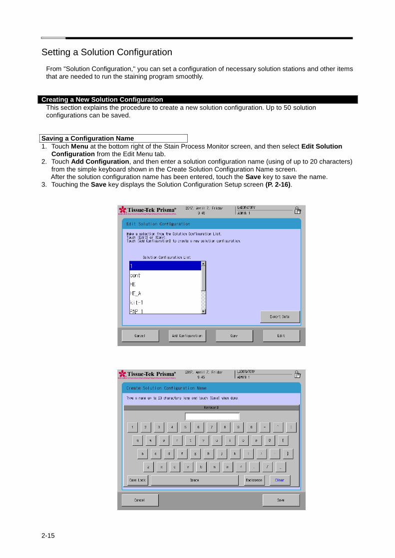
2-15
Setting a Solution Configuration From "Solution Configuration," you can set a configuration of necessary solution stations and other items that are needed to run the staining program smoothly.
Creating a New Solution Configuration
This section explains the procedure to create a new solution configuration. Up to 50 solution configurations can be saved.
Saving a Configuration Name
1. Touch Menu at the bottom right of the Stain Process Monitor screen, and then select Edit Solution Configuration from the Edit Menu tab.
2. Touch Add Configuration, and then enter a solution configuration name (using of up to 20 characters) from the simple keyboard shown in the Create Solution Configuration Name screen. After the solution configuration name has been entered, touch the Save key to save the name.
3. Touching the Save key displays the Solution Configuration Setup screen (P. 2-16).
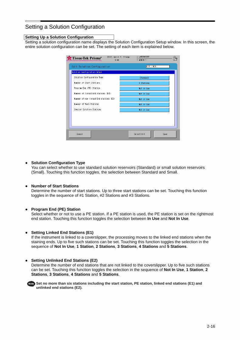
Setting a Solution Configuration
2-16
Setting Up a Solution Configuration
Setting a solution configuration name displays the Solution Configuration Setup window. In this screen, the entire solution configuration can be set. The setting of each item is explained below.
● Solution Configuration Type You can select whether to use standard solution reservoirs (Standard) or small solution reservoirs (Small). Touching this function toggles, the selection between Standard and Small.
● Number of Start Stations Determine the number of start stations. Up to three start stations can be set. Touching this function toggles in the sequence of #1 Station, #2 Stations and #3 Stations.
● Program End (PE) Station Select whether or not to use a PE station. If a PE station is used, the PE station is set on the rightmost end station. Touching this function toggles the selection between In Use and Not In Use.
● Setting Linked End Stations (E1) If the instrument is linked to a coverslipper, the processing moves to the linked end stations when the staining ends. Up to five such stations can be set. Touching this function toggles the selection in the sequence of Not In Use, 1 Station, 2 Stations, 3 Stations, 4 Stations and 5 Stations.
● Setting Unlinked End Stations (E2) Determine the number of end stations that are not linked to the coverslipper. Up to five such stations can be set. Touching this function toggles the selection in the sequence of Not In Use, 1 Station, 2 Stations, 3 Stations, 4 Stations and 5 Stations.
Set no more than six stations including the start station, PE station, linked end stations (E1) and
unlinked end stations (E2).
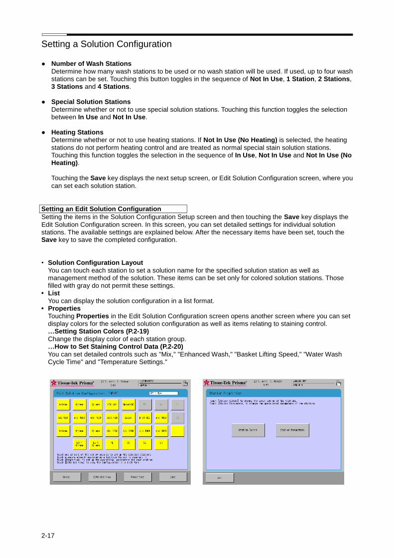
Setting a Solution Configuration
2-17
● Number of Wash Stations Determine how many wash stations to be used or no wash station will be used. If used, up to four wash stations can be set. Touching this button toggles in the sequence of Not In Use, 1 Station, 2 Stations, 3 Stations and 4 Stations.
● Special Solution Stations
Determine whether or not to use special solution stations. Touching this function toggles the selection between In Use and Not In Use.
● Heating Stations
Determine whether or not to use heating stations. If Not In Use (No Heating) is selected, the heating stations do not perform heating control and are treated as normal special stain solution stations. Touching this function toggles the selection in the sequence of In Use, Not In Use and Not In Use (No Heating).
Touching the Save key displays the next setup screen, or Edit Solution Configuration screen, where you can set each solution station.
Setting an Edit Solution Configuration
Setting the items in the Solution Configuration Setup screen and then touching the Save key displays the Edit Solution Configuration screen. In this screen, you can set detailed settings for individual solution stations. The available settings are explained below. After the necessary items have been set, touch the Save key to save the completed configuration. • Solution Configuration Layout
You can touch each station to set a solution name for the specified solution station as well as management method of the solution. These items can be set only for colored solution stations. Those filled with gray do not permit these settings.
• List You can display the solution configuration in a list format.
• Properties Touching Properties in the Edit Solution Configuration screen opens another screen where you can set display colors for the selected solution configuration as well as items relating to staining control. …Setting Station Colors (P.2-19) Change the display color of each station group. …How to Set Staining Control Data (P.2-20) You can set detailed controls such as "Mix," "Enhanced Wash," "Basket Lifting Speed," "Water Wash Cycle Time" and "Temperature Settings."
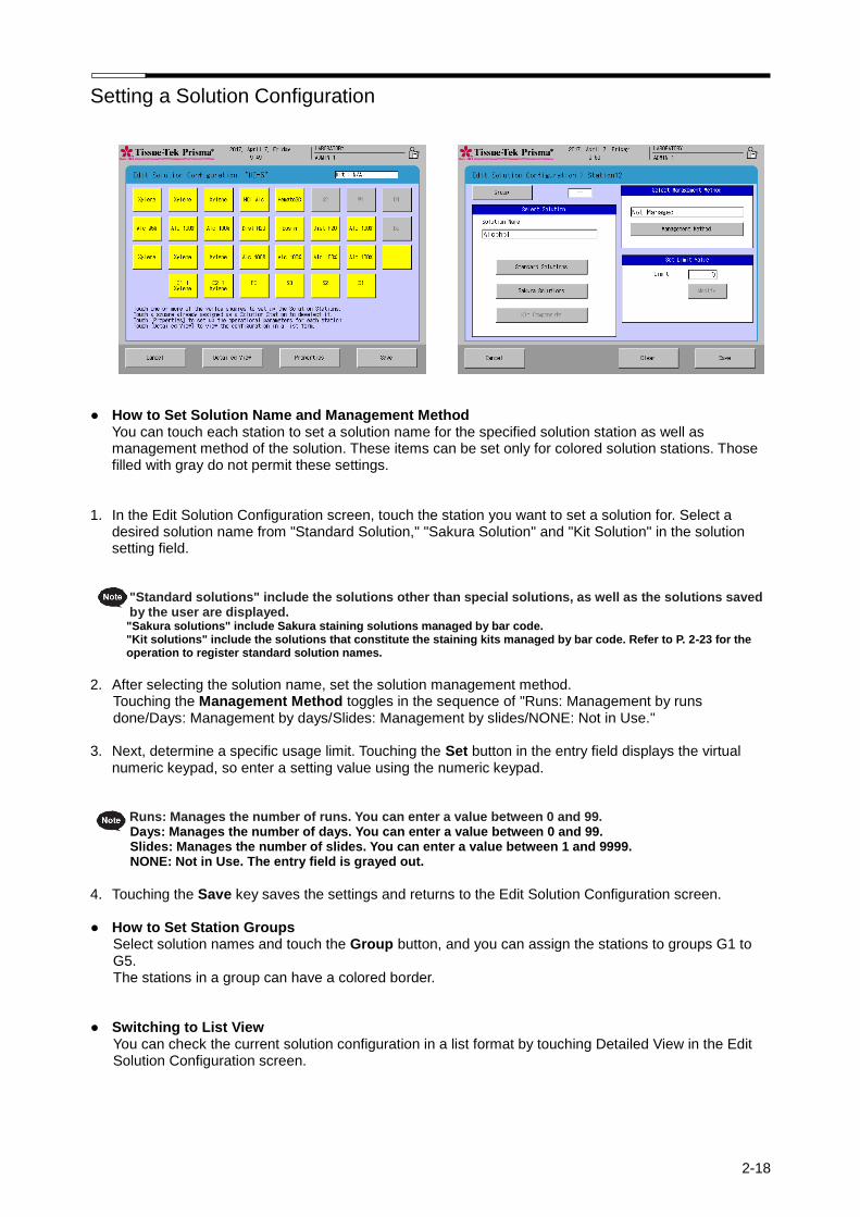
Setting a Solution Configuration
2-18
● How to Set Solution Name and Management Method You can touch each station to set a solution name for the specified solution station as well as management method of the solution. These items can be set only for colored solution stations. Those filled with gray do not permit these settings.
1. In the Edit Solution Configuration screen, touch the station you want to set a solution for. Select a desired solution name from "Standard Solution," "Sakura Solution" and "Kit Solution" in the solution setting field.
"Standard solutions" include the solutions other than special solutions, as well as the solutions saved by the user are displayed. "Sakura solutions" include Sakura staining solutions managed by bar code. "Kit solutions" include the solutions that constitute the staining kits managed by bar code. Refer to P. 2-23 for the operation to register standard solution names.
2. After selecting the solution name, set the solution management method.
Touching the Management Method toggles in the sequence of "Runs: Management by runs done/Days: Management by days/Slides: Management by slides/NONE: Not in Use."
3. Next, determine a specific usage limit. Touching the Set button in the entry field displays the virtual
numeric keypad, so enter a setting value using the numeric keypad.
Runs: Manages the number of runs. You can enter a value between 0 and 99. Days: Manages the number of days. You can enter a value between 0 and 99. Slides: Manages the number of slides. You can enter a value between 1 and 9999. NONE: Not in Use. The entry field is grayed out.
4. Touching the Save key saves the settings and returns to the Edit Solution Configuration screen.
● How to Set Station Groups
Select solution names and touch the Group button, and you can assign the stations to groups G1 to G5. The stations in a group can have a colored border.
● Switching to List View
You can check the current solution configuration in a list format by touching Detailed View in the Edit Solution Configuration screen.
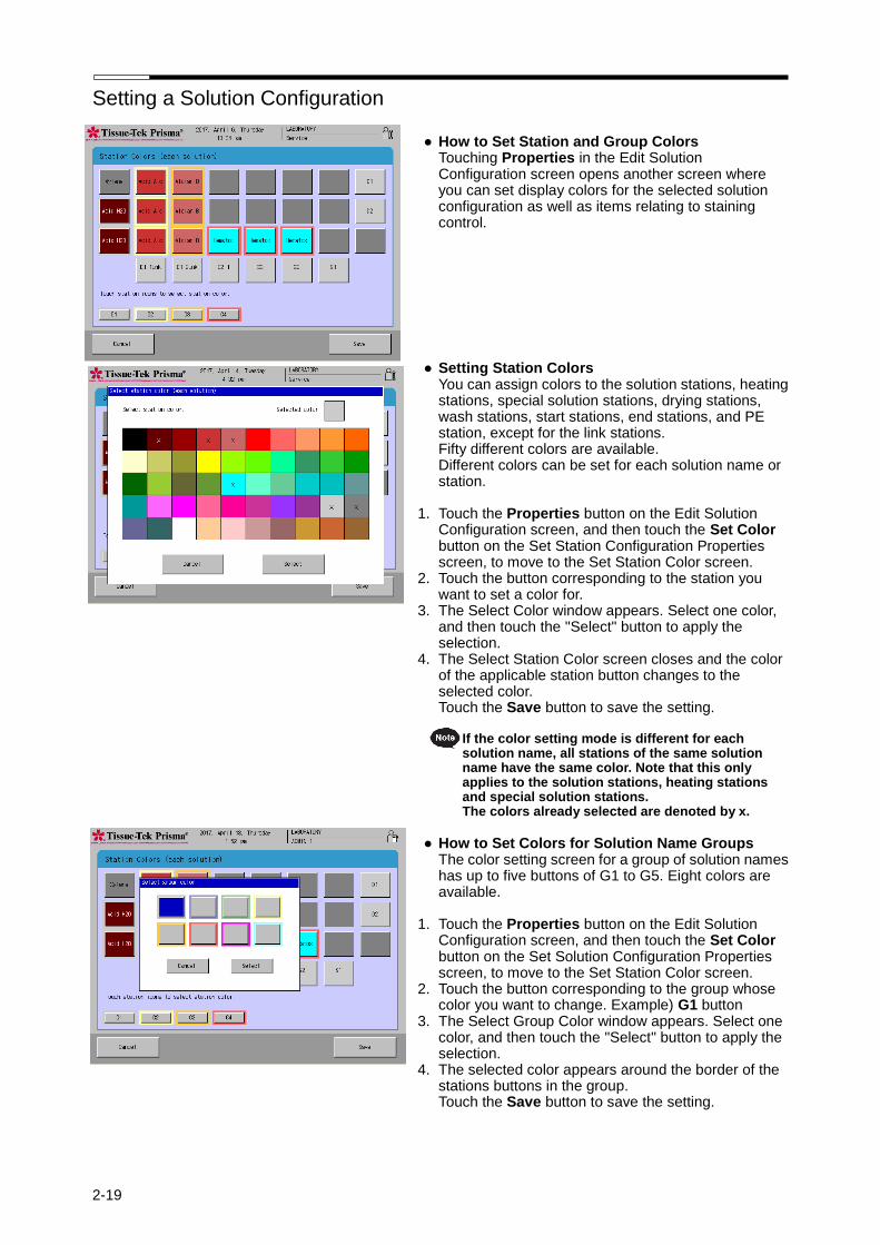
Setting a Solution Configuration
2-19
● How to Set Station and Group Colors Touching Properties in the Edit Solution Configuration screen opens another screen where you can set display colors for the selected solution configuration as well as items relating to staining control.
● Setting Station Colors You can assign colors to the solution stations, heating stations, special solution stations, drying stations, wash stations, start stations, end stations, and PE station, except for the link stations. Fifty different colors are available. Different colors can be set for each solution name or station.
1. Touch the Properties button on the Edit Solution
Configuration screen, and then touch the Set Color button on the Set Station Configuration Properties screen, to move to the Set Station Color screen.
2. Touch the button corresponding to the station you want to set a color for.
3. The Select Color window appears. Select one color, and then touch the "Select" button to apply the selection.
4. The Select Station Color screen closes and the color of the applicable station button changes to the selected color. Touch the Save button to save the setting.
If the color setting mode is different for each solution name, all stations of the same solution name have the same color. Note that this only applies to the solution stations, heating stations and special solution stations. The colors already selected are denoted by x.
● How to Set Colors for Solution Name Groups
The color setting screen for a group of solution names has up to five buttons of G1 to G5. Eight colors are available.
1. Touch the Properties button on the Edit Solution
Configuration screen, and then touch the Set Color button on the Set Solution Configuration Properties screen, to move to the Set Station Color screen.
2. Touch the button corresponding to the group whose color you want to change. Example) G1 button
3. The Select Group Color window appears. Select one color, and then touch the "Select" button to apply the selection.
4. The selected color appears around the border of the stations buttons in the group. Touch the Save button to save the setting.
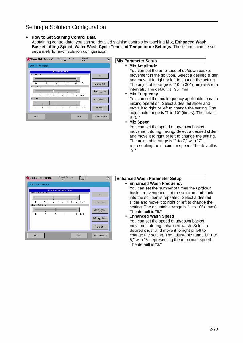
Setting a Solution Configuration
2-20
● How to Set Staining Control Data At staining control data, you can set detailed staining controls by touching Mix, Enhanced Wash, Basket Lifting Speed, Water Wash Cycle Time and Temperature Settings. These items can be set separately for each solution configuration.
Mix Parameter Setup
• Mix Amplitude You can set the amplitude of up/down basket movement in the solution. Select a desired slider and move it to right or left to change the setting. The adjustable range is "10 to 30" (mm) at 5-mm intervals. The default is "30" mm.
• Mix Frequency You can set the mix frequency applicable to each mixing operation. Select a desired slider and move it to right or left to change the setting. The adjustable range is "1 to 10" (times). The default is "5."
• Mix Speed You can set the speed of up/down basket movement during mixing. Select a desired slider and move it to right or left to change the setting. The adjustable range is "1 to 7," with "7" representing the maximum speed. The default is "3."
Enhanced Wash Parameter Setup
• Enhanced Wash Frequency You can set the number of times the up/down basket movement out of the solution and back into the solution is repeated. Select a desired slider and move it to right or left to change the setting. The adjustable range is "1 to 10" (times). The default is "5."
• Enhanced Wash Speed You can set the speed of up/down basket movement during enhanced wash. Select a desired slider and move it to right or left to change the setting. The adjustable range is "1 to 5," with "5" representing the maximum speed. The default is "3."
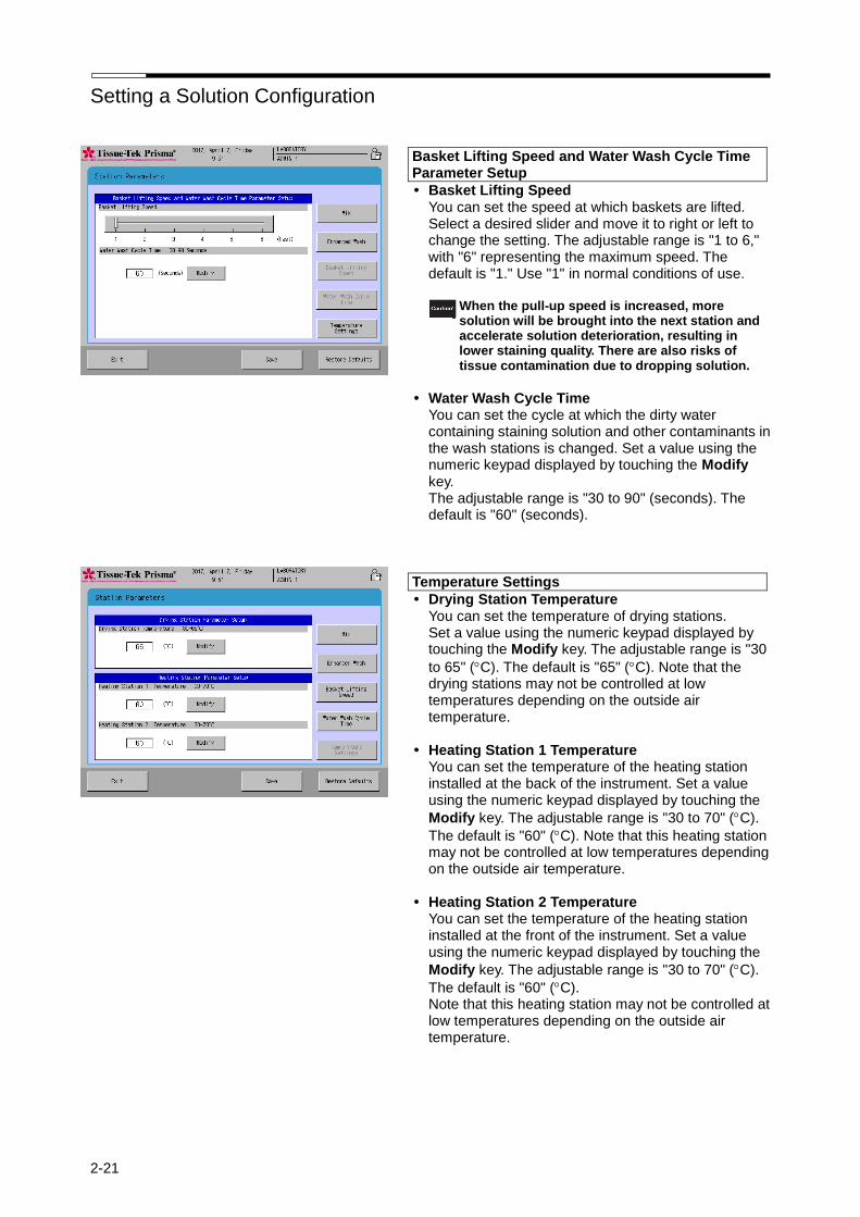
Setting a Solution Configuration
2-21
Basket Lifting Speed and Water Wash Cycle Time Parameter Setup
• Basket Lifting Speed You can set the speed at which baskets are lifted. Select a desired slider and move it to right or left to change the setting. The adjustable range is "1 to 6," with "6" representing the maximum speed. The default is "1." Use "1" in normal conditions of use.
When the pull-up speed is increased, more
solution will be brought into the next station and accelerate solution deterioration, resulting in lower staining quality. There are also risks of tissue contamination due to dropping solution.
• Water Wash Cycle Time
You can set the cycle at which the dirty water containing staining solution and other contaminants in the wash stations is changed. Set a value using the numeric keypad displayed by touching the Modify key. The adjustable range is "30 to 90" (seconds). The default is "60" (seconds).
Temperature Settings
• Drying Station Temperature You can set the temperature of drying stations. Set a value using the numeric keypad displayed by touching the Modify key. The adjustable range is "30
to 65" (C). The default is "65" (C). Note that the drying stations may not be controlled at low temperatures depending on the outside air temperature.
• Heating Station 1 Temperature You can set the temperature of the heating station installed at the back of the instrument. Set a value using the numeric keypad displayed by touching the
Modify key. The adjustable range is "30 to 70" (C).
The default is "60" (C). Note that this heating station may not be controlled at low temperatures depending on the outside air temperature.
• Heating Station 2 Temperature
You can set the temperature of the heating station installed at the front of the instrument. Set a value using the numeric keypad displayed by touching the
Modify key. The adjustable range is "30 to 70" (C).
The default is "60" (C). Note that this heating station may not be controlled at low temperatures depending on the outside air temperature.
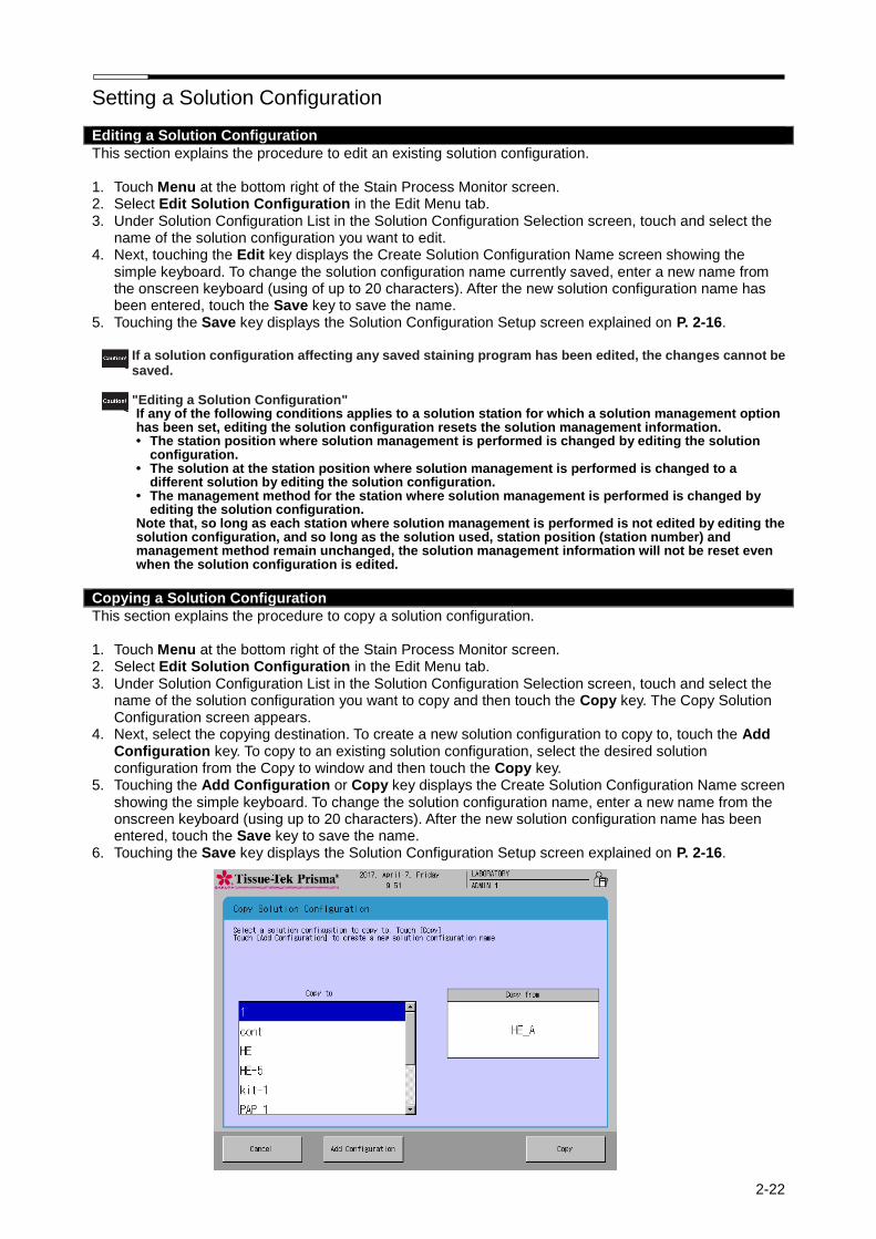
Setting a Solution Configuration
2-22
Editing a Solution Configuration
This section explains the procedure to edit an existing solution configuration.
1. Touch Menu at the bottom right of the Stain Process Monitor screen. 2. Select Edit Solution Configuration in the Edit Menu tab. 3. Under Solution Configuration List in the Solution Configuration Selection screen, touch and select the
name of the solution configuration you want to edit. 4. Next, touching the Edit key displays the Create Solution Configuration Name screen showing the
simple keyboard. To change the solution configuration name currently saved, enter a new name from the onscreen keyboard (using of up to 20 characters). After the new solution configuration name has been entered, touch the Save key to save the name.
5. Touching the Save key displays the Solution Configuration Setup screen explained on P. 2-16.
If a solution configuration affecting any saved staining program has been edited, the changes cannot be saved.
"Editing a Solution Configuration"
If any of the following conditions applies to a solution station for which a solution management option has been set, editing the solution configuration resets the solution management information. • The station position where solution management is performed is changed by editing the solution
configuration. • The solution at the station position where solution management is performed is changed to a
different solution by editing the solution configuration. • The management method for the station where solution management is performed is changed by
editing the solution configuration. Note that, so long as each station where solution management is performed is not edited by editing the solution configuration, and so long as the solution used, station position (station number) and management method remain unchanged, the solution management information will not be reset even when the solution configuration is edited.
Copying a Solution Configuration
This section explains the procedure to copy a solution configuration.
1. Touch Menu at the bottom right of the Stain Process Monitor screen. 2. Select Edit Solution Configuration in the Edit Menu tab. 3. Under Solution Configuration List in the Solution Configuration Selection screen, touch and select the
name of the solution configuration you want to copy and then touch the Copy key. The Copy Solution Configuration screen appears.
4. Next, select the copying destination. To create a new solution configuration to copy to, touch the Add Configuration key. To copy to an existing solution configuration, select the desired solution configuration from the Copy to window and then touch the Copy key.
5. Touching the Add Configuration or Copy key displays the Create Solution Configuration Name screen showing the simple keyboard. To change the solution configuration name, enter a new name from the onscreen keyboard (using up to 20 characters). After the new solution configuration name has been entered, touch the Save key to save the name.
6. Touching the Save key displays the Solution Configuration Setup screen explained on P. 2-16.
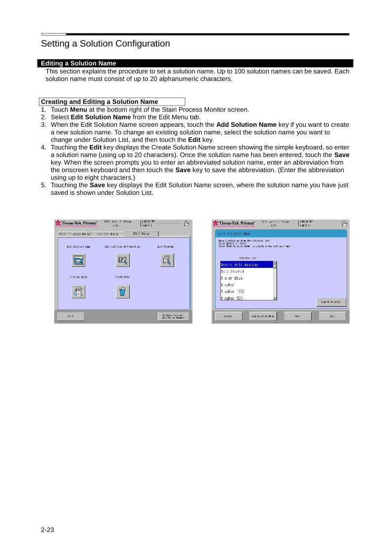
Setting a Solution Configuration
2-23
Editing a Solution Name
This section explains the procedure to set a solution name. Up to 100 solution names can be saved. Each solution name must consist of up to 20 alphanumeric characters.
Creating and Editing a Solution Name
1. Touch Menu at the bottom right of the Stain Process Monitor screen. 2. Select Edit Solution Name from the Edit Menu tab. 3. When the Edit Solution Name screen appears, touch the Add Solution Name key if you want to create
a new solution name. To change an existing solution name, select the solution name you want to change under Solution List, and then touch the Edit key.
4. Touching the Edit key displays the Create Solution Name screen showing the simple keyboard, so enter a solution name (using up to 20 characters). Once the solution name has been entered, touch the Save key. When the screen prompts you to enter an abbreviated solution name, enter an abbreviation from the onscreen keyboard and then touch the Save key to save the abbreviation. (Enter the abbreviation using up to eight characters.)
5. Touching the Save key displays the Edit Solution Name screen, where the solution name you have just saved is shown under Solution List.
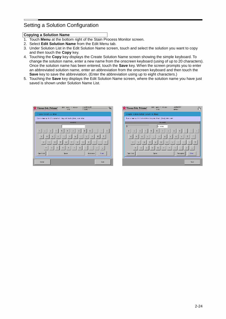
Setting a Solution Configuration
2-24
Copying a Solution Name
1. Touch Menu at the bottom right of the Stain Process Monitor screen. 2. Select Edit Solution Name from the Edit Menu tab. 3. Under Solution List in the Edit Solution Name screen, touch and select the solution you want to copy
and then touch the Copy key. 4. Touching the Copy key displays the Create Solution Name screen showing the simple keyboard. To
change the solution name, enter a new name from the onscreen keyboard (using of up to 20 characters). Once the solution name has been entered, touch the Save key. When the screen prompts you to enter an abbreviated solution name, enter an abbreviation from the onscreen keyboard and then touch the Save key to save the abbreviation. (Enter the abbreviation using up to eight characters.)
5. Touching the Save key displays the Edit Solution Name screen, where the solution name you have just saved is shown under Solution Name List.
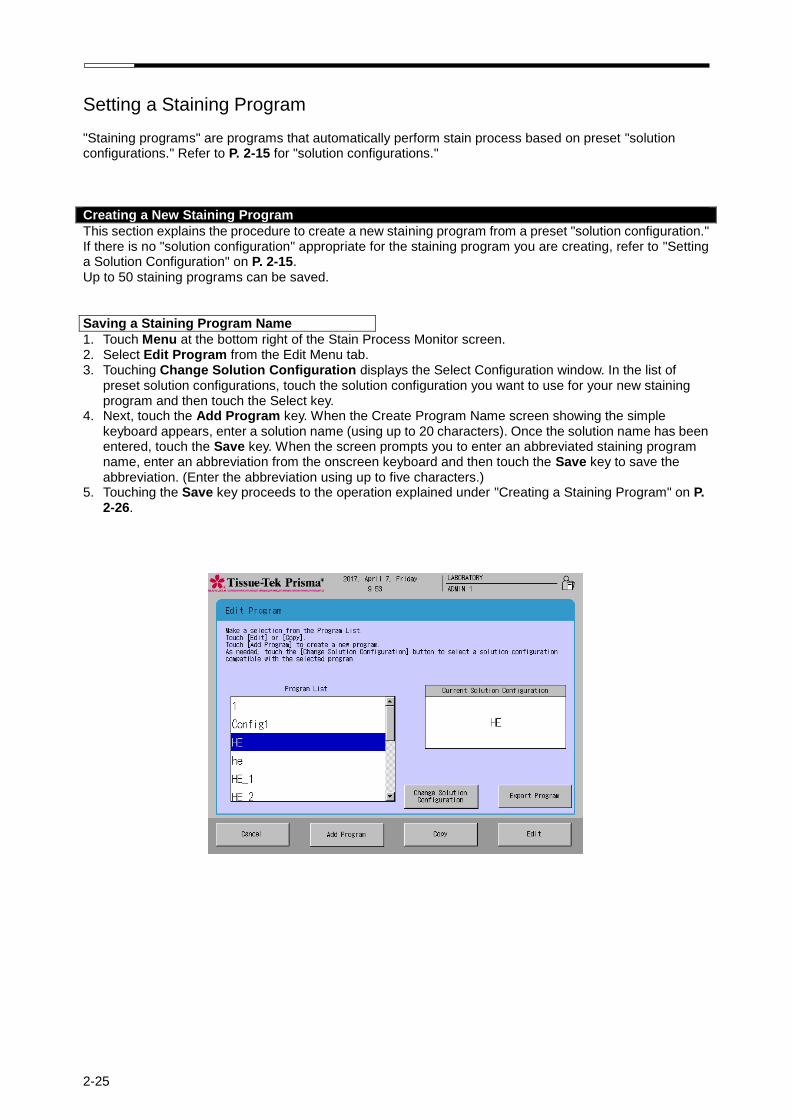
2-25
Setting a Staining Program "Staining programs" are programs that automatically perform stain process based on preset "solution configurations." Refer to P. 2-15 for "solution configurations."
Creating a New Staining Program
This section explains the procedure to create a new staining program from a preset "solution configuration." If there is no "solution configuration" appropriate for the staining program you are creating, refer to "Setting a Solution Configuration" on P. 2-15. Up to 50 staining programs can be saved.
Saving a Staining Program Name
1. Touch Menu at the bottom right of the Stain Process Monitor screen. 2. Select Edit Program from the Edit Menu tab. 3. Touching Change Solution Configuration displays the Select Configuration window. In the list of
preset solution configurations, touch the solution configuration you want to use for your new staining program and then touch the Select key.
4. Next, touch the Add Program key. When the Create Program Name screen showing the simple keyboard appears, enter a solution name (using up to 20 characters). Once the solution name has been entered, touch the Save key. When the screen prompts you to enter an abbreviated staining program name, enter an abbreviation from the onscreen keyboard and then touch the Save key to save the abbreviation. (Enter the abbreviation using up to five characters.)
5. Touching the Save key proceeds to the operation explained under "Creating a Staining Program" on P. 2-26.
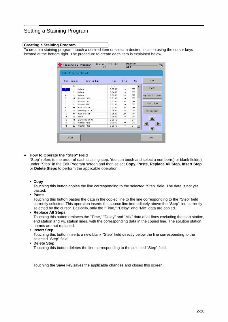
Setting a Staining Program
2-26
Creating a Staining Program
To create a staining program, touch a desired item or select a desired location using the cursor keys located at the bottom right. The procedure to create each item is explained below.
● How to Operate the "Step" Field "Step" refers to the order of each staining step. You can touch and select a number(s) or blank field(s) under "Step" in the Edit Program screen and then select Copy, Paste, Replace All Step, Insert Step or Delete Steps to perform the applicable operation.
• Copy Touching this button copies the line corresponding to the selected "Step" field. The data is not yet pasted.
• Paste Touching this button pastes the data in the copied line to the line corresponding to the "Step" field currently selected. This operation inserts the source line immediately above the "Step" line currently selected by the cursor. Basically, only the "Time," "Delay" and "Mix" data are copied.
• Replace All Steps Touching this button replaces the "Time," "Delay" and "Mix" data of all lines excluding the start station, end station and PE station lines, with the corresponding data in the copied line. The solution station names are not replaced.
• Insert Step Touching this button inserts a new blank "Step" field directly below the line corresponding to the selected "Step" field.
• Delete Step Touching this button deletes the line corresponding to the selected "Step" field.
Touching the Save key saves the applicable changes and closes this screen.

Setting a Staining Program
2-27
● How to operate the "Station" field "Station" refers to each station number assigned to the currently selected solution configuration. You can touch and select each "Station" field in the Edit Program screen and then select Select Station or Program End Station to perform the applicable operation.
• Select Station
You can select the station to be assigned to the selected "Station" field. Touching the Select Station key displays the solution configuration layout. When a desired station is touched, the data of that station is displayed at the bottom of the screen to let you check the attribute and solution name for the station. Touching the Modify key reflects the selection in the "Station" field in the Edit Program screen, with the selected station number shown in the "Station" field and applicable solution name shown in the "Solution Name" field. If a non-solution station such as start station, end station, wash station or drying station is selected, the text displayed in the "Station" field conforms to the table below.
Set an end station or stations at the end of the staining program.
• Program End Station
You can insert a PE station as a standby station in the selected line. This operation adds "PE" to the "Station" field in the Edit Program screen. For your information, the PE station is automatically set to the rightmost end station.
Touching the Save key saves the applicable changes and closes this screen.
Station attribute Text displayed in
"Station" field Text displayed in
"Solution Name" field
Start stations S * (Solution name)
End stations (linked) E1- * (Solution name)
End stations (not linked) E2- * (Solution name)
Wash stations W * Wash Station
Drying stations D * Drying Station
PE station PE (Solution name)
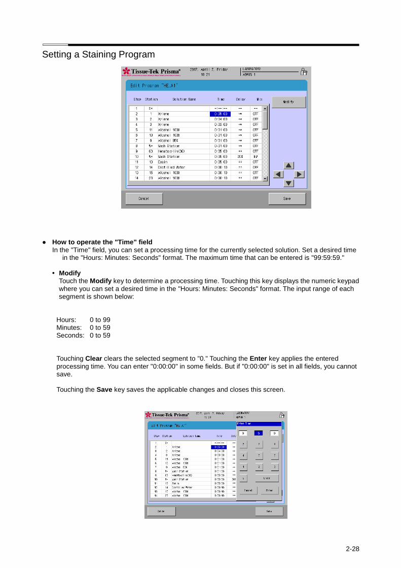
Setting a Staining Program
2-28
● How to operate the "Time" field In the "Time" field, you can set a processing time for the currently selected solution. Set a desired time
in the "Hours: Minutes: Seconds" format. The maximum time that can be entered is "99:59:59."
• Modify Touch the Modify key to determine a processing time. Touching this key displays the numeric keypad where you can set a desired time in the "Hours: Minutes: Seconds" format. The input range of each segment is shown below:
Hours: 0 to 99 Minutes: 0 to 59 Seconds: 0 to 59 Touching Clear clears the selected segment to "0." Touching the Enter key applies the entered processing time. You can enter "0:00:00" in some fields. But if "0:00:00" is set in all fields, you cannot save. Touching the Save key saves the applicable changes and closes this screen.
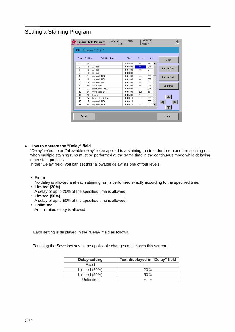
Setting a Staining Program
2-29
● How to operate the "Delay" field "Delay" refers to an "allowable delay" to be applied to a staining run in order to run another staining run when multiple staining runs must be performed at the same time in the continuous mode while delaying other stain process. In the "Delay" field, you can set this "allowable delay" as one of four levels.
• Exact No delay is allowed and each staining run is performed exactly according to the specified time.
• Limited (20%) A delay of up to 20% of the specified time is allowed.
• Limited (50%) A delay of up to 50% of the specified time is allowed.
• Unlimited An unlimited delay is allowed.
Each setting is displayed in the "Delay" field as follows. Touching the Save key saves the applicable changes and closes this screen.
Delay setting Text displayed in "Delay" field
Exact ==
Limited (20%) 20%
Limited (50%) 50%
Unlimited * *
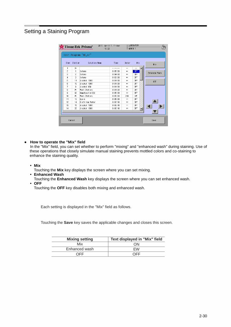
Setting a Staining Program
2-30
● How to operate the "Mix" field
In the "Mix" field, you can set whether to perform "mixing" and "enhanced wash" during staining. Use of these operations that closely simulate manual staining prevents mottled colors and co-staining to enhance the staining quality.
• Mix Touching the Mix key displays the screen where you can set mixing.
• Enhanced Wash Touching the Enhanced Wash key displays the screen where you can set enhanced wash.
• OFF Touching the OFF key disables both mixing and enhanced wash.
Each setting is displayed in the "Mix" field as follows.
Touching the Save key saves the applicable changes and closes this screen.
Mixing setting Text displayed in "Mix" field
Mix ON
Enhanced wash EW
OFF OFF
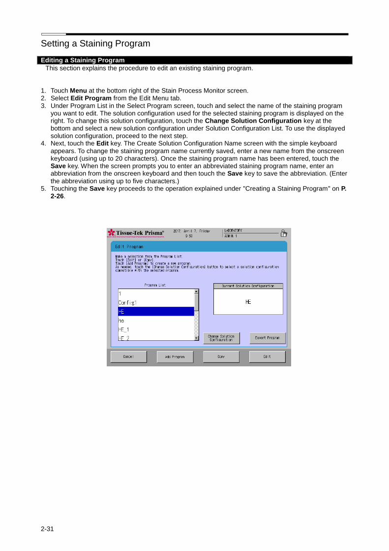
Setting a Staining Program
2-31
Editing a Staining Program
This section explains the procedure to edit an existing staining program.
1. Touch Menu at the bottom right of the Stain Process Monitor screen. 2. Select Edit Program from the Edit Menu tab. 3. Under Program List in the Select Program screen, touch and select the name of the staining program
you want to edit. The solution configuration used for the selected staining program is displayed on the right. To change this solution configuration, touch the Change Solution Configuration key at the bottom and select a new solution configuration under Solution Configuration List. To use the displayed solution configuration, proceed to the next step.
4. Next, touch the Edit key. The Create Solution Configuration Name screen with the simple keyboard appears. To change the staining program name currently saved, enter a new name from the onscreen keyboard (using up to 20 characters). Once the staining program name has been entered, touch the Save key. When the screen prompts you to enter an abbreviated staining program name, enter an abbreviation from the onscreen keyboard and then touch the Save key to save the abbreviation. (Enter the abbreviation using up to five characters.)
5. Touching the Save key proceeds to the operation explained under "Creating a Staining Program" on P. 2-26.

Setting a Staining Program
2-32
Copying a Staining Program
This section explains the procedure to copy a staining program.
1. Touch Menu at the bottom right of the Stain Process Monitor screen. 2. Select Edit Program from the Edit Menu tab. 3. Under Program List in the Select Program screen, touch and select the name of the staining program
you want to copy, and then touch the Copy key. The Copy Program screen appears. 4. Next, select the copying destination. To create a new solution configuration to copy to, touch the Add
Configuration key. To copy to an existing program, select the desired program from the Copy to window and then touch the Copy key.
5. Touching the Add Program or Copy key displays the Create Solution Configuration Name screen showing the simple keyboard. To change the staining program name, enter a new name from the onscreen keyboard (using up to 20 characters). Once the staining program name has been entered, touch the Save key. When the screen prompts you to enter an abbreviated staining program name, enter an abbreviation from the onscreen keyboard and then touch the Save key to save the abbreviation. (Enter the abbreviation using up to five characters.)
6. Touching the Save key proceeds to the operation explained under "Creating a Staining Program" on P. 2-26.

Setting a Staining Program
2-33
Checking a Staining Program
This section explains the procedure to check if a given combination of solution configuration and staining program is feasible.
1. Touch Menu at the bottom right of the Stain Process Monitor screen. 2. Select Program Check from the Edit Menu tab. 3. When the Program Check screen appears, select the solution configuration you want to check under
Solution Configuration List. Next, select the staining program you want to check under Program List. 4 After both the program and solution configuration have been selected, touch the Check key at the
bottom right. The "Program Check Result" screen appears. 5. This screen shows problems with the selected combination, if any. If necessary, change the staining
program and/or solution configuration by referring to the displayed check result to correct the problems.
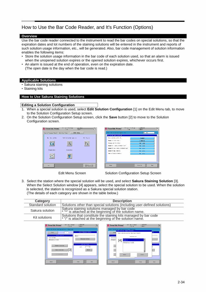
2-34
How to Use the Bar Code Reader, and It's Function (Options)
Overview
Use the bar code reader connected to the instrument to read the bar codes on special solutions, so that the expiration dates and lot numbers of the staining solutions will be entered in the instrument and reports of such solution usage information, etc., will be generated. Also, bar code management of solution information enables the following items: • Store the solution usage information in the bar code of each solution used, so that an alarm is issued
when the unopened solution expires or the opened solution expires, whichever occurs first. • An alarm is issued at the end of operation, even on the expiration date.
(The open date is the day when the bar code is read.)
Applicable Solutions
• Sakura staining solutions • Staining kits
How to Use Sakura Staining Solutions
Editing a Solution Configuration
1. When a special solution is used, select Edit Solution Configuration [1] on the Edit Menu tab, to move to the Solution Configuration Setup screen.
2. On the Solution Configuration Setup screen, click the Save button [2] to move to the Solution Configuration screen.
Edit Menu Screen Solution Configuration Setup Screen
3. Select the station where the special solution will be used, and select Sakura Staining Solution [3]. When the Select Solution window [4] appears, select the special solution to be used. When the solution is selected, the station is recognized as a Sakura special solution station. (The details of each category are shown in the table below.)
Category Description
Standard solution Solutions other than special solutions (including user-defined solutions)
Sakura solution Sakura staining solutions managed by bar code * "*" is attached at the beginning of the solution name.
Kit solutions Solutions that constitute the staining kits managed by bar code * "/" is attached at the beginning of the solution name.
[3] [3]
[4]
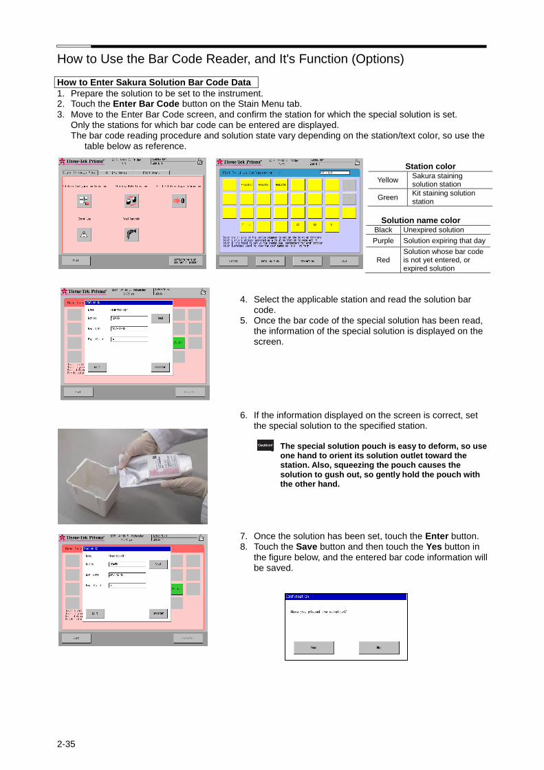
How to Use the Bar Code Reader, and It's Function (Options)
2-35
How to Enter Sakura Solution Bar Code Data
1. Prepare the solution to be set to the instrument. 2. Touch the Enter Bar Code button on the Stain Menu tab. 3. Move to the Enter Bar Code screen, and confirm the station for which the special solution is set.
Only the stations for which bar code can be entered are displayed. The bar code reading procedure and solution state vary depending on the station/text color, so use the
table below as reference.
Station color
Yellow Sakura staining solution station
Green Kit staining solution station
Solution name color
Black Unexpired solution
Purple Solution expiring that day
Red Solution whose bar code is not yet entered, or expired solution
4. Select the applicable station and read the solution bar code.
5. Once the bar code of the special solution has been read, the information of the special solution is displayed on the screen.
6. If the information displayed on the screen is correct, set the special solution to the specified station.
The special solution pouch is easy to deform, so use
one hand to orient its solution outlet toward the station. Also, squeezing the pouch causes the solution to gush out, so gently hold the pouch with the other hand.
7. Once the solution has been set, touch the Enter button. 8. Touch the Save button and then touch the Yes button in
the figure below, and the entered bar code information will be saved.

How to Use the Bar Code Reader, and It's Function (Options)
2-36
How to Use Sakura Staining Kit
Editing a Solution Configuration
1. When a staining kit is used, select Edit Solution Configuration [1] on the Edit Menu tab, to move to the Solution Configuration Setup screen.
2. On the Solution Configuration Setup screen, touch the Select Kit button [2] to display the Select Staining Kit window, and then set the staining kit used for the solution configuration.
Edit Menu Screen Solution Configuration Setup Screen
3. For the specified station, select Kit Solution [4] from the categories shown in [3]. (The details of each category are shown in the table below.)
Category Description Standard solution Solutions other than special solutions (including user-defined solutions)
Sakura solution Sakura staining solutions managed by bar code * "*" is attached at the beginning of the solution name.
Kit solutions Solutions that constitute the staining kits managed by bar code * "/" is attached at the beginning of the solution name.
Touching the Kit Components button [4] displays the Select Solution Kit Components window [5], so select the solution you want to assign to the station. When the solution is selected, the station is recognized as a kit component solution station.
[1]
[2]
[5]
[4]
[3]

How to Use the Bar Code Reader, and It's Function (Options)
2-37
How to Enter Kit Component Solution Bar Code Data
1. Prepare the solution to be set to the instrument. 2. Touch the Enter Bar Code button on the Stain Menu tab. 3. Move to the Enter Bar Code screen, and confirm the station for which the special solution is set.
Only the stations for which bar code can be entered are displayed. The bar code reading procedure and solution state vary depending on the station/text color, so use the
table below as reference.
Station color
Yellow Sakura staining solution station
Green Kit staining solution station
Solution name color
Black Unexpired solution
Purple Solution expiring that day
Red Solution whose bar code is not yet entered, or expired solution
4. Select the station for which the kit is set, and read the bar code of the kit.
5. Once the kit has been read, the information of the kit is displayed on the screen. If the information displayed on the screen is correct, touch the Enter button.
6. The bar code of the kit component solution is read.
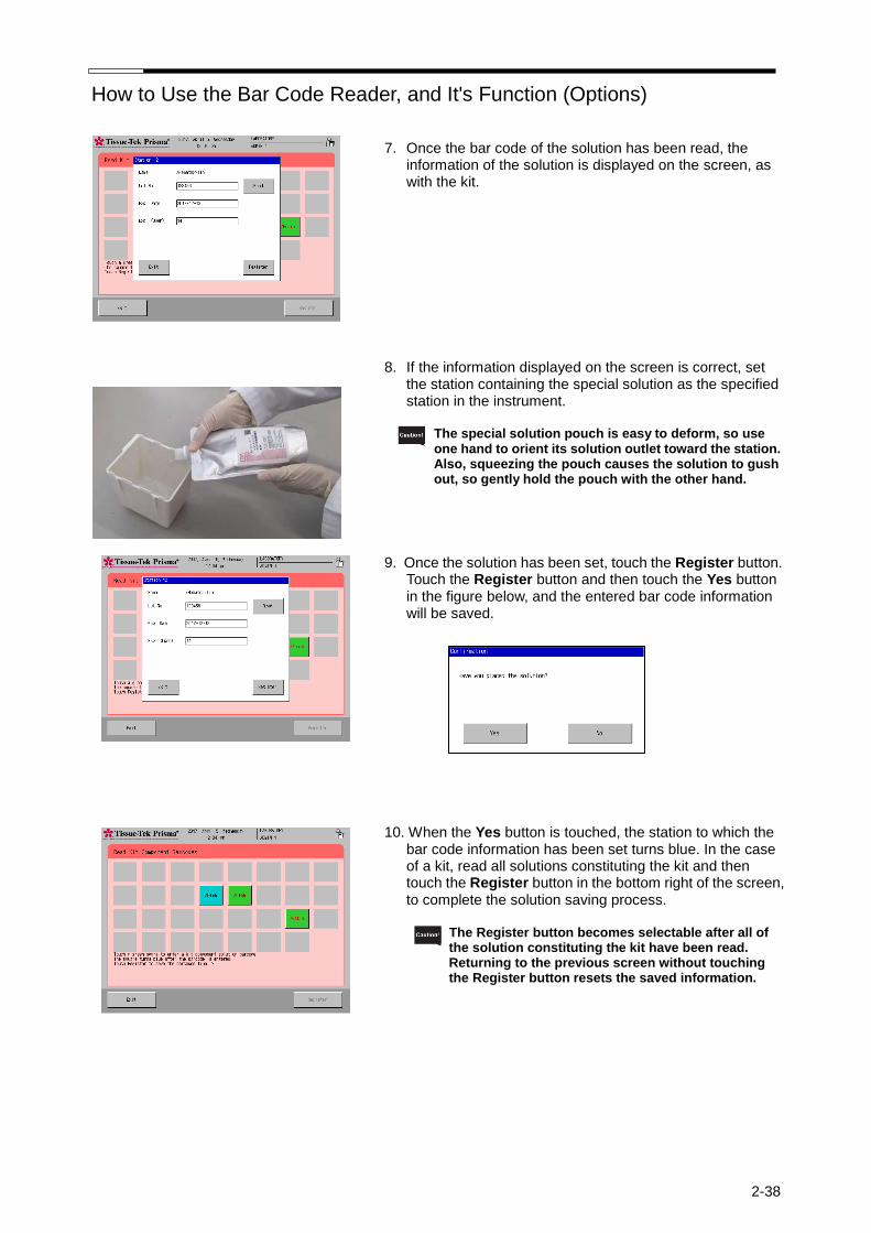
How to Use the Bar Code Reader, and It's Function (Options)
2-38
7. Once the bar code of the solution has been read, the
information of the solution is displayed on the screen, as with the kit.
8. If the information displayed on the screen is correct, set
the station containing the special solution as the specified station in the instrument.
The special solution pouch is easy to deform, so use
one hand to orient its solution outlet toward the station. Also, squeezing the pouch causes the solution to gush out, so gently hold the pouch with the other hand.
9. Once the solution has been set, touch the Register button.
Touch the Register button and then touch the Yes button in the figure below, and the entered bar code information will be saved.
10. When the Yes button is touched, the station to which the
bar code information has been set turns blue. In the case of a kit, read all solutions constituting the kit and then touch the Register button in the bottom right of the screen, to complete the solution saving process.
The Register button becomes selectable after all of the solution constituting the kit have been read. Returning to the previous screen without touching the Register button resets the saved information.

How to Use the Bar Code Reader, and It's Function (Options)
2-39
Resetting the Solution Usage Information
You can select the Reset Solution Usage Information screen from the Stain Menu and check for expired solutions and reset their usage information. You can also move to the Read Bar Code screen from the Reset Solution Usage Information screen.
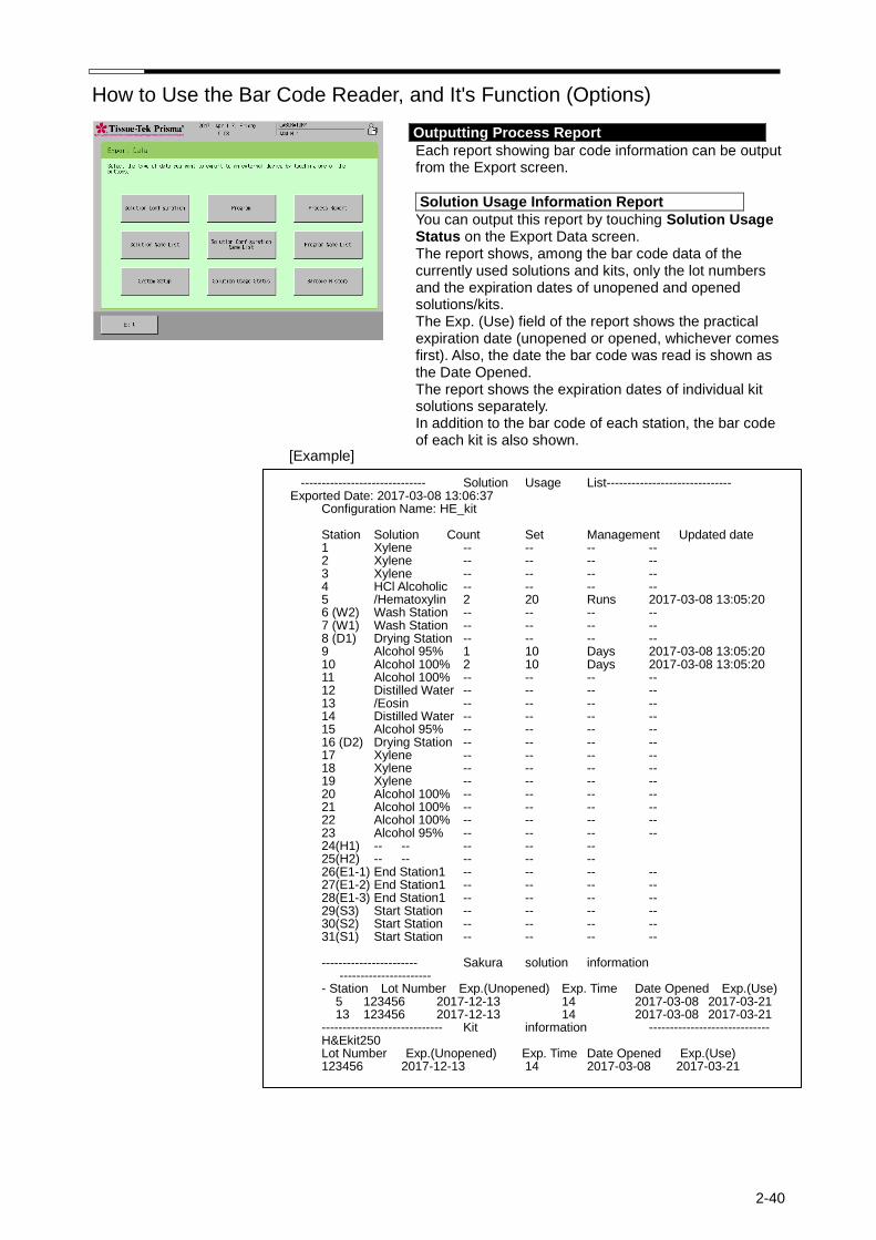
How to Use the Bar Code Reader, and It's Function (Options)
2-40
Outputting Process Report
Each report showing bar code information can be output from the Export screen.
Solution Usage Information Report
You can output this report by touching Solution Usage Status on the Export Data screen. The report shows, among the bar code data of the currently used solutions and kits, only the lot numbers and the expiration dates of unopened and opened solutions/kits. The Exp. (Use) field of the report shows the practical expiration date (unopened or opened, whichever comes first). Also, the date the bar code was read is shown as the Date Opened. The report shows the expiration dates of individual kit solutions separately. In addition to the bar code of each station, the bar code of each kit is also shown.
[Example]
------------------------------ Solution Usage List------------------------------ Exported Date: 2017-03-08 13:06:37
Configuration Name: HE_kit Station Solution Count Set Management Updated date 1 Xylene -- -- -- -- 2 Xylene -- -- -- -- 3 Xylene -- -- -- -- 4 HCl Alcoholic -- -- -- -- 5 /Hematoxylin 2 20 Runs 2017-03-08 13:05:20 6 (W2) Wash Station -- -- -- -- 7 (W1) Wash Station -- -- -- -- 8 (D1) Drying Station -- -- -- -- 9 Alcohol 95% 1 10 Days 2017-03-08 13:05:20 10 Alcohol 100% 2 10 Days 2017-03-08 13:05:20 11 Alcohol 100% -- -- -- -- 12 Distilled Water -- -- -- -- 13 /Eosin -- -- -- -- 14 Distilled Water -- -- -- -- 15 Alcohol 95% -- -- -- -- 16 (D2) Drying Station -- -- -- -- 17 Xylene -- -- -- -- 18 Xylene -- -- -- -- 19 Xylene -- -- -- -- 20 Alcohol 100% -- -- -- -- 21 Alcohol 100% -- -- -- -- 22 Alcohol 100% -- -- -- -- 23 Alcohol 95% -- -- -- -- 24(H1) -- -- -- -- -- 25(H2) -- -- -- -- -- 26(E1-1) End Station1 -- -- -- -- 27(E1-2) End Station1 -- -- -- -- 28(E1-3) End Station1 -- -- -- -- 29(S3) Start Station -- -- -- -- 30(S2) Start Station -- -- -- -- 31(S1) Start Station -- -- -- -- ----------------------- Sakura solution information ---------------------- - Station Lot Number Exp.(Unopened) Exp. Time Date Opened Exp.(Use)
5 123456 2017-12-13 14 2017-03-08 2017-03-21 13 123456 2017-12-13 14 2017-03-08 2017-03-21
----------------------------- Kit information ----------------------------- H&Ekit250 Lot Number Exp.(Unopened) Exp. Time Date Opened Exp.(Use) 123456 2017-12-13 14 2017-03-08 2017-03-21

How to Use the Bar Code Reader, and It's Function (Options)
2-41
Process Report
You can output this report by touching Process Report on the Export screen. The report shows, among the bar code data of the currently used solutions and kits, only the lot numbers and the expiration dates of unopened and opened solutions/kits. The Exp. (Use) field of the report shows the practical expiration date (unopened or opened, whichever comes first). Also, the date the bar code was read is shown as the Date Opened. The report shows the expiration dates of individual kit solutions separately. The solution usage status at the end of processing is shown. In addition to the bar code of each station, the bar code of each kit is also shown. The Usage field shows the solution usage status. In the case of a group, the stations actually used, and the usage status of each station used, are shown.
[Example]
--------------------------- Process Report -------------------------- Exported Date: 2017-03-08 1:07:06 PM
Start:2017-03-08 11:27:34 End :2017-03-08 12:06:33
Program Name: HE_kit Specimen No : 2
Step Station Solution Time Result Delay Mix Usage
1 S* Start Station --:--:-- 00:00:14 2 1 Xylene 00:05:00 00:05:00 ** ON 3 2 Xylene 00:04:00 00:04:00 ** ON 4 3 Xylene 00:03:00 00:03:00 ** ON 5 11 Alcohol 100% 00:01:00 00:01:00 ** ON 6 10 Alcohol 100% 00:01:00 00:01:00 ** ON 7 9 Alcohol 95% 00:01:00 00:01:00 ** ON 8 W* Wash Station 00:01:00 00:01:00 ** ON 9 5 /Hematoxylin 00:05:00 00:05:00 == ON Runs 11/20 10 W* Wash Station 00:05:00 00:05:00 20% EW 11 13 /Eosin 00:05:00 00:05:00 == ON 12 14 Distilled Water 00:00:10 00:00:10 == ON 13 15 Alcohol 95% 00:00:10 00:00:10 == ON Days 1/10 14 23 Alcohol 95% 00:00:10 00:00:10 == ON Days 2/10 15 22 Alcohol 100% 00:01:00 00:01:00 20% ON 16 21 Alcohol 100% 00:01:00 00:01:00 20% ON 17 20 Alcohol 100% 00:01:00 00:01:00 ** ON 18 19 Xylene 00:01:00 00:01:00 ** ON 19 18 Xylene 00:01:00 00:01:00 ** ON 20 17 Xylene 00:01:00 00:01:00 ** ON 21 E1-* End Station 1 --:--:-- 00:58:53
----------------------- Sakura solution information ----------------------
- Station Lot Number Exp.(Unopened) Exp. Time Date Opened Exp.(Use)
5 123456 2017-12-13 14 2017-03-08 2017-03-21 6 123456 12/25/17 14 01/05/17 01/18/17 13 123456 12/13/2017 14 3/8/2017 3/21/2017 14 123456 12/13/2017 14 1/5/2017 1/18/2017
----------------------------- Kit information ----------------------------- H&Ekit250
Lot Number Exp.(Unopened) Exp. Time Date Opened Exp.(Use)
123456 2017-12-13 14 2017-03-08 2017-03-21

How to Use the Bar Code Reader, and It's Function (Options)
2-42
Solution Configuration Report
You can output this report by touching Solution Configuration List on the Export Data screen. The solution configuration report also shows the staining kit name.
[Example] --------------------- Solution Configuration List ------------------- Exported Date: 2017-03-08 13:06:46 Created Date : 2017-01-27 10:40:34 Revised Date : 2017-03-08 10:37:23
Configuration Name:HE_kit Kit Name:H&Ekit250 Station Solution Set Management
1 Xylene -- -- 2 Xylene 10 Runs 3 Xylene 10 Runs 4 HCl Alcoholic -- -- 5 /Hematoxylin -- -- 6 (W2) Wash Station -- -- 7 (W1) Wash Station -- -- 8 (D1) Drying Station -- -- 9 Alcohol 95% -- - 10 Alcohol 100% -- -- 11 Alcohol 100% -- -- 12 Distilled Water -- -- 13 /Eosin -- -- 14 Distilled Water -- -- 15 Alcohol 95% -- -- 16(D2) Drying Station -- -- 17 Xylene -- -- 18 Xylene -- -- 19 Xylene -- -- 20 Alcohol 100% -- -- 21 Alcohol 100% -- -- 22 Alcohol 100% -- -- 23 Alcohol 95% -- -- 24(H1) -- -- -- 25(H2) -- -- -- 26(E1-1) End Station 1 -- -- 27(E1-2) End Station 1 -- -- 28(E1-3) End Station 1 -- -- 29(S3) Start Station -- -- 30(S2) Start Station -- -- 31(S1) Start Station -- -- ------------------------ Color Information -------------------------- G1 Green G2 Cream G3 Yellow G4 Pink G5 Magenta
------------------------- Station Parameters ------------------------ Mix Amplitude 30 mm Mix Frequency 5 Mix Speed 3 Enhanced Wash Frequency 5 Enhanced Wash Speed 3 Basket Lifting Speed 1 Water Wash Cycle Time 60 seconds Drying Station Temperature 65 C. Heating Station(1) Temperature 60 C. Heating Station(2) Temperature 60 C. Heat up Heating Stations Yes

How to Use the Bar Code Reader, and It's Function (Options)
2-43
Barcode History Report
You can output this report by touching Barcode History on the Export Data screen. The barcode history shows the GTIN of each barcode that has been read, lot number, and the date the barcode was read, for up to 1,000 most recently read barcodes.
[Example]
Barcode History report --------------------------- Barcode History --------------------------
Exported Date: 2015-06-27 16:47:23
GTIN Lot Number Date Opened
04560133241122 316510 06/19/15
04560133241105 216513 06/19/15
04560133241105 216514 06/19/15
04560133241207 116511 06/19/15
04560133241115 516215 06/15/15
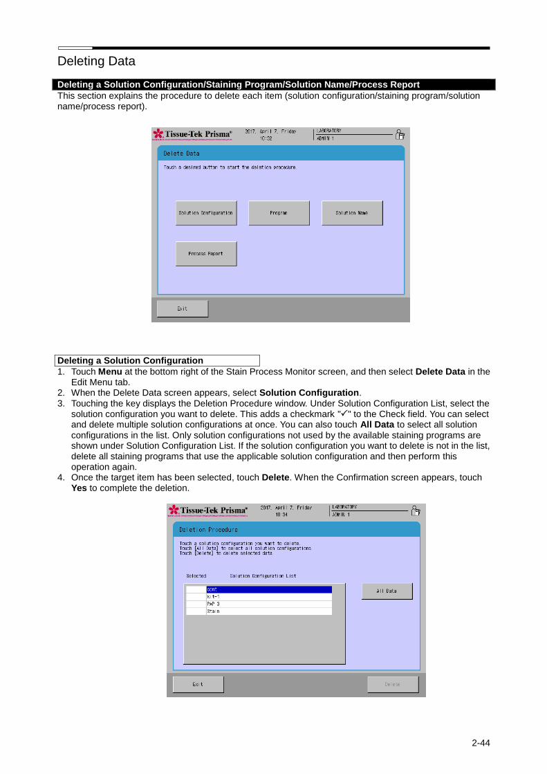
Deleting Data
2-44
Deleting a Solution Configuration/Staining Program/Solution Name/Process Report
This section explains the procedure to delete each item (solution configuration/staining program/solution name/process report).
Deleting a Solution Configuration
1. Touch Menu at the bottom right of the Stain Process Monitor screen, and then select Delete Data in the Edit Menu tab.
2. When the Delete Data screen appears, select Solution Configuration. 3. Touching the key displays the Deletion Procedure window. Under Solution Configuration List, select the
solution configuration you want to delete. This adds a checkmark "" to the Check field. You can select and delete multiple solution configurations at once. You can also touch All Data to select all solution configurations in the list. Only solution configurations not used by the available staining programs are shown under Solution Configuration List. If the solution configuration you want to delete is not in the list, delete all staining programs that use the applicable solution configuration and then perform this operation again.
4. Once the target item has been selected, touch Delete. When the Confirmation screen appears, touch Yes to complete the deletion.
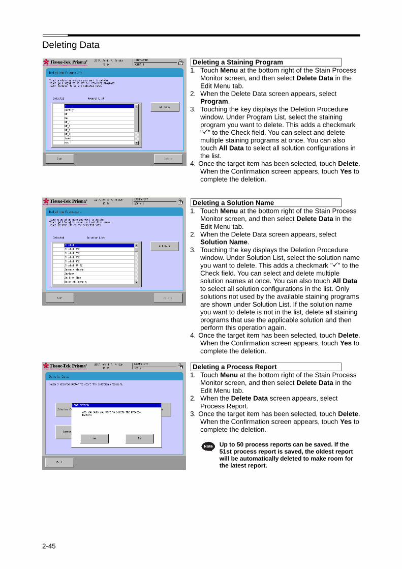
Deleting Data
2-45
Deleting a Staining Program
1. Touch Menu at the bottom right of the Stain Process Monitor screen, and then select Delete Data in the Edit Menu tab.
2. When the Delete Data screen appears, select Program.
3. Touching the key displays the Deletion Procedure window. Under Program List, select the staining program you want to delete. This adds a checkmark "" to the Check field. You can select and delete multiple staining programs at once. You can also touch All Data to select all solution configurations in the list.
4. Once the target item has been selected, touch Delete. When the Confirmation screen appears, touch Yes to complete the deletion.
Deleting a Solution Name
1. Touch Menu at the bottom right of the Stain Process Monitor screen, and then select Delete Data in the Edit Menu tab.
2. When the Delete Data screen appears, select Solution Name.
3. Touching the key displays the Deletion Procedure window. Under Solution List, select the solution name you want to delete. This adds a checkmark "" to the Check field. You can select and delete multiple solution names at once. You can also touch All Data to select all solution configurations in the list. Only solutions not used by the available staining programs are shown under Solution List. If the solution name you want to delete is not in the list, delete all staining programs that use the applicable solution and then perform this operation again.
4. Once the target item has been selected, touch Delete. When the Confirmation screen appears, touch Yes to complete the deletion.
Deleting a Process Report
1. Touch Menu at the bottom right of the Stain Process Monitor screen, and then select Delete Data in the Edit Menu tab.
2. When the Delete Data screen appears, select Process Report.
3. Once the target item has been selected, touch Delete. When the Confirmation screen appears, touch Yes to complete the deletion.
Up to 50 process reports can be saved. If the
51st process report is saved, the oldest report will be automatically deleted to make room for the latest report.

2-46
Action to Be Taken upon Power Outage
Power Recovery Operation
This section explains the operation to be performed if a power outage occurred during the stain process. Once the power is restored, perform the power recovery operation explained below.
1. Once the power is restored, an error buzzer sounds and the Power Outage Alarm screen or Arm Error window appears on the control panel display to inform the operator that a power outage has occurred.
2. The operator must evacuate the arm to the initial position according to the onscreen instruction. If any basket is currently set on the arm, remove the basket from the arm according to the onscreen instruction and then place it in the station shown in brown.
3. To resume stain process, touch the Resume key. Because of the power outage, the staining may not end by the initially scheduled end time. In this case, the specified time may be delayed by up to the period after the power outage occurred until the Resume key was touched.
4. To abort stain process, touch the Abort key. Refer to P. 2-11 for the method to abort staining.
A prolonged power outage may cause the tissues to dry up or result in staining problems. If you know that a power outage will occur, do not use the instrument. If a prolonged power outage has occurred due to an unexpected problem, take an appropriate action to prevent the tissues from drying up, and then manually perform the remainder of the staining process.

2-47
Action to Be Taken upon Error
Error Handling
During operation, the instrument may stop after displaying an error. This section explains the actions to be taken when errors occur. Most errors accompany a number. Some errors temporarily stop the series of operations such as staining runs, while other errors display a caution/confirmation window prompting the operator to check the applicable items. Representative error/caution/confirmation screens are shown below.
Errors with a Number
Most errors accompany a number and are displayed as follows. You can check the action to be taken against each error by referring to the section corresponding to the applicable number in Chapter 4, "Troubleshooting." If further assistance is needed regarding your particular problem, if the problem persists after taking the specified action, or if the specific problem you have encountered is not listed, contact the Sakura Finetek Technical Support representative or local representative.
Other Errors
If the error does not accompany a number, follow the onscreen instruction shown in the error window.
In the event of an unexpected problem for which you cannot find any solution, immediately turn off the power. Next, open the hood, remove the tissues, and protect them so as not to let them dry up. Then, contact the Sakura Finetek Technical Support representative or local representative.

Chapter 3 Maintenance and Inspection

3-1
Daily Inspection and Cleaning
Inspection and Cleaning Methods
Inspect and clean the instrument periodically to prevent instrument malfunction and failure. Unless otherwise specified in this manual, perform inspection and cleaning with the power turned off.
Cleaning the Solution Reservoirs and Baskets
Clean solution reservoirs and baskets with water or neutral detergent. If solution has attached to a reservoir/basket and the color or stain does not come off easily, soak the reservoir/basket in a commercial chemical dye cleaner or bleach (diluted to the manufacturer’s instruction), and then clean with neutral detergent. Sometimes cleaning does not fully remove built-up stains. To prevent stains from building up, it is recommended that the solution reservoirs/baskets be cleaned after each staining. Alternatively, use different solution reservoirs/baskets for each solution so that the reservoirs/baskets with solution stains can still be used.
Cleaning the Drying Stations
In the instrument, the two rightmost stations located at the back are drying stations. First, remove the two special attachments from the drying stations. Next, clean the stations using neutral detergent, and then wipe down with a dry cloth. Store the stations by following the removal steps in the reverse order. If the drying stations are not set properly, the drying function will not operate properly.
Cleaning the Heating Stations
In the instrument, the two rightmost stations located at the front are heating stations. Remove the heating stations by holding the two tongues at the edges of the heating station. Exercise due caution when handling the heating stations, because these stations remain very hot immediately after any operation in which the heating stations have been used. To clean the heating stations, clean with neutral detergent and then wipe down with a dry cloth. After cleaning, store the stations in the original positions. The interior of the heating stations is coated with Teflon. When cleaning, make sure the coating is not rubbed with sharp edges, as the coating will be scraped off.
Special heating station reservoir
Attachment Paraffin tray
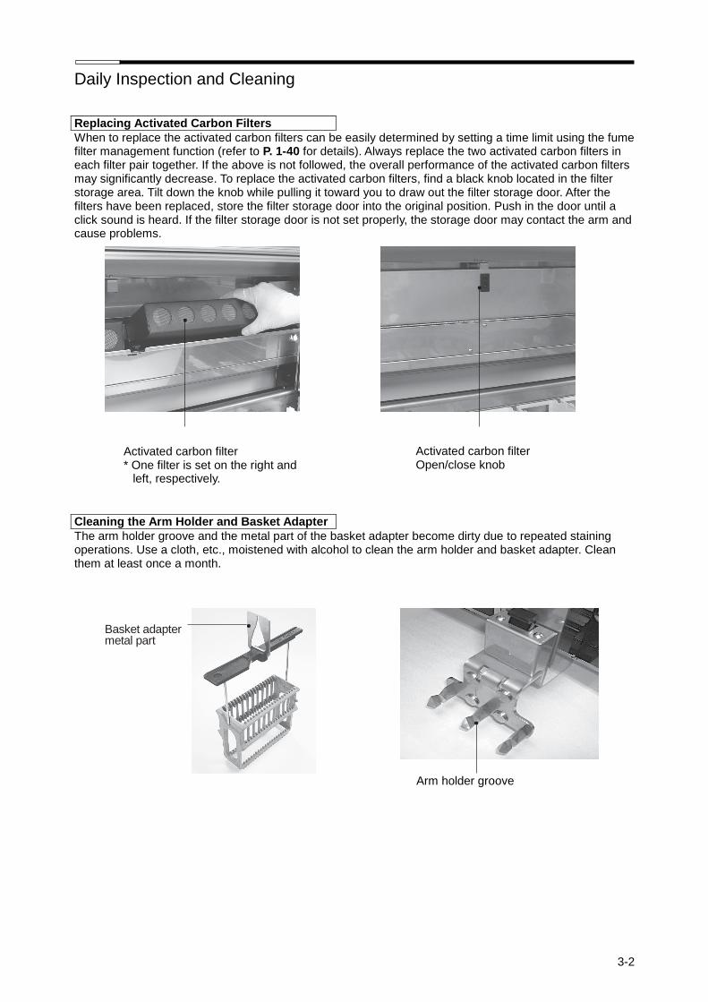
Daily Inspection and Cleaning
3-2
Replacing Activated Carbon Filters
When to replace the activated carbon filters can be easily determined by setting a time limit using the fume filter management function (refer to P. 1-40 for details). Always replace the two activated carbon filters in each filter pair together. If the above is not followed, the overall performance of the activated carbon filters may significantly decrease. To replace the activated carbon filters, find a black knob located in the filter storage area. Tilt down the knob while pulling it toward you to draw out the filter storage door. After the filters have been replaced, store the filter storage door into the original position. Push in the door until a click sound is heard. If the filter storage door is not set properly, the storage door may contact the arm and cause problems.
Cleaning the Arm Holder and Basket Adapter
The arm holder groove and the metal part of the basket adapter become dirty due to repeated staining operations. Use a cloth, etc., moistened with alcohol to clean the arm holder and basket adapter. Clean them at least once a month.
Basket adapter metal part
Arm holder groove
Activated carbon filter * One filter is set on the right and
left, respectively.
Activated carbon filter Open/close knob

Daily Inspection and Cleaning
3-3
Cleaning the Water Supply Strainer (Excluding Prisama-P-ED, ES)
Close the main water valve. Open the water supply strainer door at the bottom right of the system. Opening the hood makes opening the door easier. Use a wrench of 17 mm across flats to turn the lid counterclockwise and remove the lid. Water in the pipe will come out, so use a container, etc., to catch the water. Wash the strainer with water using a brush, etc. After washing the strainer, dry and assemble the strainer, and screw in the lid. Open the water supply plug and confirm that no water leaks from the strainer. Clean the strainer once a month or so. After the cleaning, perform a water supply test by referring to P. 1-41.
Cleaning the Cabinet
Clean the entire storage space for the system and solution stations as well as the sink and pans at least once a month. Remove all trays from the cabinet and clean them using a cloth moistened with water. Also clean the trays with neutral detergent, and then wipe down with a dry cloth.
In addition to the interior of the instrument, also clean the hood, door and around the exhaust port
regularly. At this time, be sure to turn off the power and disconnect the power plug from the power outlet. Failure to do so may result in electric shock.
<Corrosion Protection> The Tissue-Tek Prisma uses corrosion-resistant stainless steel, but the stainless steel may rust depending on a combination of factors such as the environment (water, air), staining method (type of solution, concentration), use method (handling of solvent, maintenance), etc. Take note of the following points to protect the instrument from corrosion. Keep the solution reservoir lids closed except during the staining process. Remove those solution reservoirs containing highly corrosive solutions, from the trays, and keep the solutions outside the instrument. If a highly corrosive solution spilled in the instrument, wipe it off immediately. Remove all solution trays (including the solution reservoirs) from the instrument once a week or so, wipe down the trays using a cloth moistened with water, clean them with neutral detergent, and wipe down with a dry cloth.
Corrosive solutions
Acids [hydrochloric acid (HCL), hydrobromic acid (Hbr), hydrofluoric acid (HF), etc.] and staining solutions containing an acid
Reagent solutions [Schiff’s reagent, cold Schiff, sulfurous acid solution, resorcin‐fuchsin staining
solution, etc.] Oxidizing chlorides [ferric chloride (FeCl3), sodium tiosulfate (Na22O3), organic acid (HCOOH), acetic acid (CH3COOH), bromic acid (C204H2), lactic acid (CH3CH(OH)COOH), etc.)]
If this is not performed, the metal parts may corrode (rust, etc.) quickly. Contact the Sakura Finetek Technical Support representative or local representative for use of metal cleaners.
Water supply strainer lid Water supply strainer mesh

Daily Inspection and Cleaning
3-4
Cleaning the Wash Station Nozzle
Remove the wash station nozzle and clean each part using neutral detergent. Since this is a wash station, the nozzle need not be wiped down. However, preform a water supply test after installing the nozzle and setting the solution reservoir, to confirm that the wash station nozzle has been connected correctly. Refer to P. 1-12 for the installation/removal of the wash station nozzle, or P. 1-41 for the water supply test.
Cleaning the Drain Hose
If the drain hose at the back of the stainer is clogged, staining may be affected and unwanted problems may result. To prevent such problems, clean the drain hose at least once a month. Remove the drain hose from the drain elbow and clean the inside of the hose using tap water. If the hose is still clogged after the cleaning or is cracked and leaking water, etc., replace the hose with a new one. Refer to P. 1-9 for the installation method of the drain hose. If you have any question regarding cleaning, contact the Sakura Finetek Technical Support representative or local representative.

Chapter 4 Troubleshooting

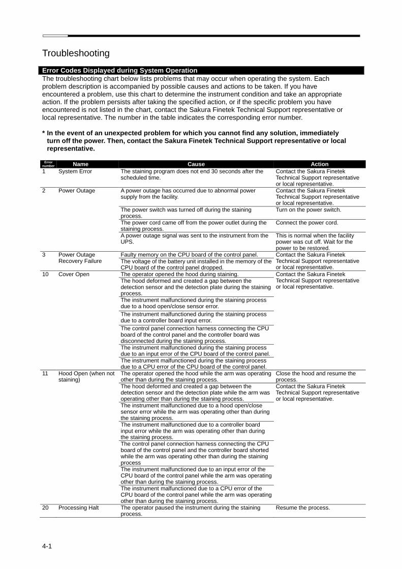
4-1
Troubleshooting
Error Codes Displayed during System Operation
The troubleshooting chart below lists problems that may occur when operating the system. Each problem description is accompanied by possible causes and actions to be taken. If you have encountered a problem, use this chart to determine the instrument condition and take an appropriate action. If the problem persists after taking the specified action, or if the specific problem you have encountered is not listed in the chart, contact the Sakura Finetek Technical Support representative or local representative. The number in the table indicates the corresponding error number.
* In the event of an unexpected problem for which you cannot find any solution, immediately
turn off the power. Then, contact the Sakura Finetek Technical Support representative or local representative.
Error
number Name Cause Action
1 System Error The staining program does not end 30 seconds after the scheduled time.
Contact the Sakura Finetek Technical Support representative or local representative.
2 Power Outage A power outage has occurred due to abnormal power supply from the facility.
Contact the Sakura Finetek Technical Support representative or local representative.
The power switch was turned off during the staining process.
Turn on the power switch.
The power cord came off from the power outlet during the staining process.
Connect the power cord.
A power outage signal was sent to the instrument from the UPS.
This is normal when the facility power was cut off. Wait for the power to be restored.
3 Power Outage Recovery Failure
Faulty memory on the CPU board of the control panel. Contact the Sakura Finetek Technical Support representative or local representative.
The voltage of the battery unit installed in the memory of the CPU board of the control panel dropped.
10 Cover Open The operator opened the hood during staining. Contact the Sakura Finetek Technical Support representative or local representative.
The hood deformed and created a gap between the detection sensor and the detection plate during the staining process. The instrument malfunctioned during the staining process due to a hood open/close sensor error.
The instrument malfunctioned during the staining process due to a controller board input error.
The control panel connection harness connecting the CPU board of the control panel and the controller board was disconnected during the staining process. The instrument malfunctioned during the staining process due to an input error of the CPU board of the control panel. The instrument malfunctioned during the staining process due to a CPU error of the CPU board of the control panel.
11 Hood Open (when not staining)
The operator opened the hood while the arm was operating other than during the staining process.
Close the hood and resume the process.
The hood deformed and created a gap between the detection sensor and the detection plate while the arm was operating other than during the staining process.
Contact the Sakura Finetek Technical Support representative or local representative.
The instrument malfunctioned due to a hood open/close sensor error while the arm was operating other than during the staining process. The instrument malfunctioned due to a controller board input error while the arm was operating other than during the staining process. The control panel connection harness connecting the CPU board of the control panel and the controller board shorted while the arm was operating other than during the staining process The instrument malfunctioned due to an input error of the CPU board of the control panel while the arm was operating other than during the staining process. The instrument malfunctioned due to a CPU error of the CPU board of the control panel while the arm was operating other than during the staining process.
20 Processing Halt The operator paused the instrument during the staining process.
Resume the process.
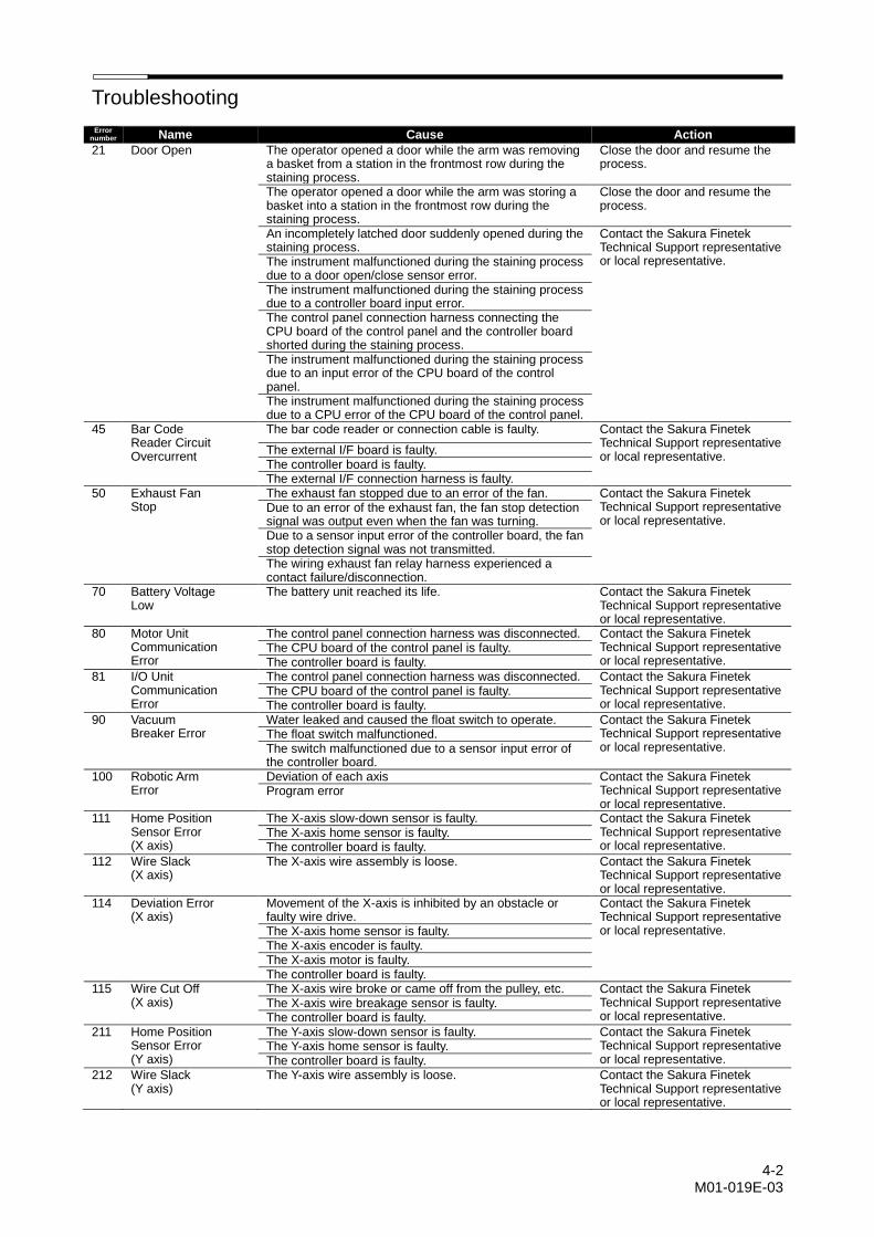
Troubleshooting
4-2 M01-019E-03
Error number Name Cause Action
21 Door Open The operator opened a door while the arm was removing a basket from a station in the frontmost row during the staining process.
Close the door and resume the process.
The operator opened a door while the arm was storing a basket into a station in the frontmost row during the staining process.
Close the door and resume the process.
An incompletely latched door suddenly opened during the staining process.
Contact the Sakura Finetek Technical Support representative or local representative. The instrument malfunctioned during the staining process
due to a door open/close sensor error. The instrument malfunctioned during the staining process due to a controller board input error. The control panel connection harness connecting the CPU board of the control panel and the controller board shorted during the staining process. The instrument malfunctioned during the staining process due to an input error of the CPU board of the control panel. The instrument malfunctioned during the staining process due to a CPU error of the CPU board of the control panel.
45 Bar Code Reader Circuit Overcurrent
The bar code reader or connection cable is faulty. Contact the Sakura Finetek Technical Support representative or local representative.
The external I/F board is faulty. The controller board is faulty. The external I/F connection harness is faulty.
50 Exhaust Fan Stop
The exhaust fan stopped due to an error of the fan. Contact the Sakura Finetek Technical Support representative or local representative.
Due to an error of the exhaust fan, the fan stop detection signal was output even when the fan was turning. Due to a sensor input error of the controller board, the fan stop detection signal was not transmitted. The wiring exhaust fan relay harness experienced a contact failure/disconnection.
70 Battery Voltage Low
The battery unit reached its life. Contact the Sakura Finetek Technical Support representative or local representative.
80 Motor Unit Communication Error
The control panel connection harness was disconnected. Contact the Sakura Finetek Technical Support representative or local representative.
The CPU board of the control panel is faulty. The controller board is faulty.
81 I/O Unit Communication Error
The control panel connection harness was disconnected. Contact the Sakura Finetek Technical Support representative or local representative.
The CPU board of the control panel is faulty. The controller board is faulty.
90 Vacuum Breaker Error
Water leaked and caused the float switch to operate. Contact the Sakura Finetek Technical Support representative or local representative.
The float switch malfunctioned. The switch malfunctioned due to a sensor input error of the controller board.
100 Robotic Arm Error
Deviation of each axis Contact the Sakura Finetek Technical Support representative or local representative.
Program error
111 Home Position Sensor Error (X axis)
The X-axis slow-down sensor is faulty. Contact the Sakura Finetek Technical Support representative or local representative.
The X-axis home sensor is faulty. The controller board is faulty.
112 Wire Slack (X axis)
The X-axis wire assembly is loose. Contact the Sakura Finetek Technical Support representative or local representative.
114 Deviation Error (X axis)
Movement of the X-axis is inhibited by an obstacle or faulty wire drive.
Contact the Sakura Finetek Technical Support representative or local representative. The X-axis home sensor is faulty.
The X-axis encoder is faulty. The X-axis motor is faulty. The controller board is faulty.
115 Wire Cut Off (X axis)
The X-axis wire broke or came off from the pulley, etc. Contact the Sakura Finetek Technical Support representative or local representative.
The X-axis wire breakage sensor is faulty. The controller board is faulty.
211 Home Position Sensor Error (Y axis)
The Y-axis slow-down sensor is faulty. Contact the Sakura Finetek Technical Support representative or local representative.
The Y-axis home sensor is faulty. The controller board is faulty.
212 Wire Slack (Y axis)
The Y-axis wire assembly is loose. Contact the Sakura Finetek Technical Support representative or local representative.
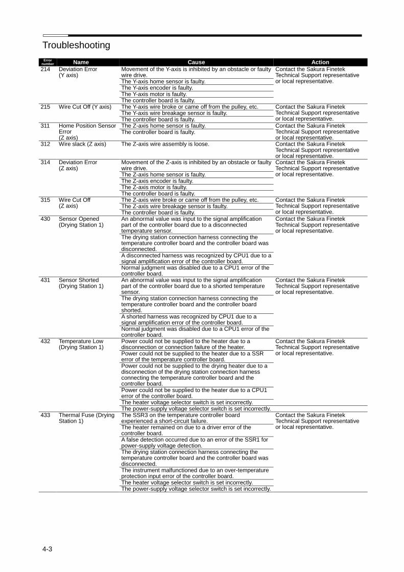
Troubleshooting
4-3
Error number Name Cause Action
214 Deviation Error (Y axis)
Movement of the Y-axis is inhibited by an obstacle or faulty wire drive.
Contact the Sakura Finetek Technical Support representative or local representative. The Y-axis home sensor is faulty.
The Y-axis encoder is faulty. The Y-axis motor is faulty. The controller board is faulty.
215 Wire Cut Off (Y axis) The Y-axis wire broke or came off from the pulley, etc. Contact the Sakura Finetek Technical Support representative or local representative.
The Y-axis wire breakage sensor is faulty. The controller board is faulty.
311 Home Position Sensor Error (Z axis)
The Z-axis home sensor is faulty. Contact the Sakura Finetek Technical Support representative or local representative.
The controller board is faulty.
312 Wire slack (Z axis) The Z-axis wire assembly is loose. Contact the Sakura Finetek Technical Support representative or local representative.
314 Deviation Error (Z axis)
Movement of the Z-axis is inhibited by an obstacle or faulty wire drive.
Contact the Sakura Finetek Technical Support representative or local representative. The Z-axis home sensor is faulty.
The Z-axis encoder is faulty. The Z-axis motor is faulty. The controller board is faulty.
315 Wire Cut Off (Z axis)
The Z-axis wire broke or came off from the pulley, etc. Contact the Sakura Finetek Technical Support representative or local representative.
The Z-axis wire breakage sensor is faulty. The controller board is faulty.
430 Sensor Opened (Drying Station 1)
An abnormal value was input to the signal amplification part of the controller board due to a disconnected temperature sensor.
Contact the Sakura Finetek Technical Support representative or local representative.
The drying station connection harness connecting the temperature controller board and the controller board was disconnected. A disconnected harness was recognized by CPU1 due to a signal amplification error of the controller board. Normal judgment was disabled due to a CPU1 error of the controller board.
431 Sensor Shorted (Drying Station 1)
An abnormal value was input to the signal amplification part of the controller board due to a shorted temperature sensor.
Contact the Sakura Finetek Technical Support representative or local representative.
The drying station connection harness connecting the temperature controller board and the controller board shorted. A shorted harness was recognized by CPU1 due to a signal amplification error of the controller board. Normal judgment was disabled due to a CPU1 error of the controller board.
432 Temperature Low (Drying Station 1)
Power could not be supplied to the heater due to a disconnection or connection failure of the heater.
Contact the Sakura Finetek Technical Support representative or local representative. Power could not be supplied to the heater due to a SSR
error of the temperature controller board. Power could not be supplied to the drying heater due to a disconnection of the drying station connection harness connecting the temperature controller board and the controller board. Power could not be supplied to the heater due to a CPU1 error of the controller board. The heater voltage selector switch is set incorrectly. The power-supply voltage selector switch is set incorrectly.
433 Thermal Fuse (Drying Station 1)
The SSR3 on the temperature controller board experienced a short-circuit failure.
Contact the Sakura Finetek Technical Support representative or local representative. The heater remained on due to a driver error of the
controller board. A false detection occurred due to an error of the SSR1 for power-supply voltage detection. The drying station connection harness connecting the temperature controller board and the controller board was disconnected. The instrument malfunctioned due to an over-temperature protection input error of the controller board. The heater voltage selector switch is set incorrectly. The power-supply voltage selector switch is set incorrectly.
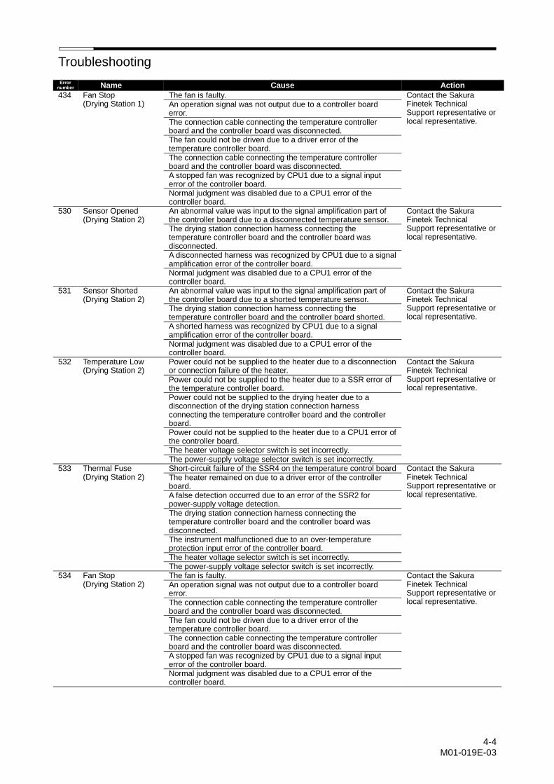
Troubleshooting
4-4 M01-019E-03
Error number Name Cause Action
434 Fan Stop (Drying Station 1)
The fan is faulty. Contact the Sakura Finetek Technical Support representative or local representative.
An operation signal was not output due to a controller board error. The connection cable connecting the temperature controller board and the controller board was disconnected. The fan could not be driven due to a driver error of the temperature controller board. The connection cable connecting the temperature controller board and the controller board was disconnected. A stopped fan was recognized by CPU1 due to a signal input error of the controller board. Normal judgment was disabled due to a CPU1 error of the controller board.
530 Sensor Opened (Drying Station 2)
An abnormal value was input to the signal amplification part of the controller board due to a disconnected temperature sensor.
Contact the Sakura Finetek Technical Support representative or local representative.
The drying station connection harness connecting the temperature controller board and the controller board was disconnected. A disconnected harness was recognized by CPU1 due to a signal amplification error of the controller board. Normal judgment was disabled due to a CPU1 error of the controller board.
531 Sensor Shorted (Drying Station 2)
An abnormal value was input to the signal amplification part of the controller board due to a shorted temperature sensor.
Contact the Sakura Finetek Technical Support representative or local representative.
The drying station connection harness connecting the temperature controller board and the controller board shorted. A shorted harness was recognized by CPU1 due to a signal amplification error of the controller board. Normal judgment was disabled due to a CPU1 error of the controller board.
532 Temperature Low (Drying Station 2)
Power could not be supplied to the heater due to a disconnection or connection failure of the heater.
Contact the Sakura Finetek Technical Support representative or local representative.
Power could not be supplied to the heater due to a SSR error of the temperature controller board. Power could not be supplied to the drying heater due to a disconnection of the drying station connection harness connecting the temperature controller board and the controller board. Power could not be supplied to the heater due to a CPU1 error of the controller board. The heater voltage selector switch is set incorrectly. The power-supply voltage selector switch is set incorrectly.
533 Thermal Fuse (Drying Station 2)
Short-circuit failure of the SSR4 on the temperature control board Contact the Sakura Finetek Technical Support representative or local representative.
The heater remained on due to a driver error of the controller board. A false detection occurred due to an error of the SSR2 for power-supply voltage detection. The drying station connection harness connecting the temperature controller board and the controller board was disconnected. The instrument malfunctioned due to an over-temperature protection input error of the controller board. The heater voltage selector switch is set incorrectly. The power-supply voltage selector switch is set incorrectly.
534 Fan Stop (Drying Station 2)
The fan is faulty. Contact the Sakura Finetek Technical Support representative or local representative.
An operation signal was not output due to a controller board error. The connection cable connecting the temperature controller board and the controller board was disconnected. The fan could not be driven due to a driver error of the temperature controller board. The connection cable connecting the temperature controller board and the controller board was disconnected. A stopped fan was recognized by CPU1 due to a signal input error of the controller board. Normal judgment was disabled due to a CPU1 error of the controller board.
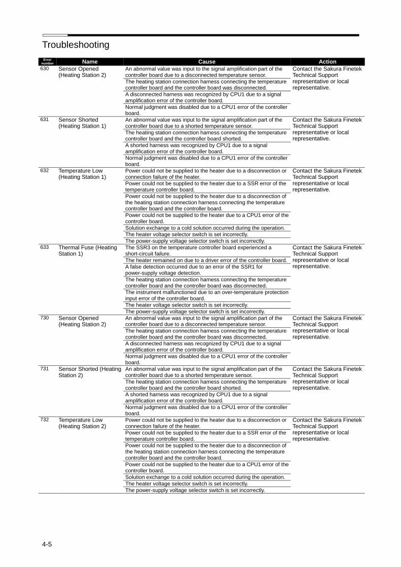
Troubleshooting
4-5
Error number Name Cause Action 630 Sensor Opened
(Heating Station 2) An abnormal value was input to the signal amplification part of the controller board due to a disconnected temperature sensor.
Contact the Sakura Finetek Technical Support representative or local representative.
The heating station connection harness connecting the temperature controller board and the controller board was disconnected.
A disconnected harness was recognized by CPU1 due to a signal amplification error of the controller board.
Normal judgment was disabled due to a CPU1 error of the controller board.
631 Sensor Shorted (Heating Station 1)
An abnormal value was input to the signal amplification part of the controller board due to a shorted temperature sensor.
Contact the Sakura Finetek Technical Support representative or local representative.
The heating station connection harness connecting the temperature controller board and the controller board shorted.
A shorted harness was recognized by CPU1 due to a signal amplification error of the controller board.
Normal judgment was disabled due to a CPU1 error of the controller board.
632 Temperature Low (Heating Station 1)
Power could not be supplied to the heater due to a disconnection or connection failure of the heater.
Contact the Sakura Finetek Technical Support representative or local representative.
Power could not be supplied to the heater due to a SSR error of the temperature controller board.
Power could not be supplied to the heater due to a disconnection of the heating station connection harness connecting the temperature controller board and the controller board.
Power could not be supplied to the heater due to a CPU1 error of the controller board.
Solution exchange to a cold solution occurred during the operation.
The heater voltage selector switch is set incorrectly.
The power-supply voltage selector switch is set incorrectly. 633 Thermal Fuse (Heating
Station 1) The SSR3 on the temperature controller board experienced a short-circuit failure.
Contact the Sakura Finetek Technical Support representative or local representative.
The heater remained on due to a driver error of the controller board.
A false detection occurred due to an error of the SSR1 for power-supply voltage detection.
The heating station connection harness connecting the temperature controller board and the controller board was disconnected.
The instrument malfunctioned due to an over-temperature protection input error of the controller board.
The heater voltage selector switch is set incorrectly.
The power-supply voltage selector switch is set incorrectly. 730 Sensor Opened
(Heating Station 2) An abnormal value was input to the signal amplification part of the controller board due to a disconnected temperature sensor.
Contact the Sakura Finetek Technical Support representative or local representative.
The heating station connection harness connecting the temperature controller board and the controller board was disconnected.
A disconnected harness was recognized by CPU1 due to a signal amplification error of the controller board.
Normal judgment was disabled due to a CPU1 error of the controller board.
731 Sensor Shorted (Heating Station 2)
An abnormal value was input to the signal amplification part of the controller board due to a shorted temperature sensor.
Contact the Sakura Finetek Technical Support representative or local representative.
The heating station connection harness connecting the temperature controller board and the controller board shorted.
A shorted harness was recognized by CPU1 due to a signal amplification error of the controller board.
Normal judgment was disabled due to a CPU1 error of the controller board.
732 Temperature Low (Heating Station 2)
Power could not be supplied to the heater due to a disconnection or connection failure of the heater.
Contact the Sakura Finetek Technical Support representative or local representative.
Power could not be supplied to the heater due to a SSR error of the temperature controller board.
Power could not be supplied to the heater due to a disconnection of the heating station connection harness connecting the temperature controller board and the controller board.
Power could not be supplied to the heater due to a CPU1 error of the controller board.
Solution exchange to a cold solution occurred during the operation.
The heater voltage selector switch is set incorrectly.
The power-supply voltage selector switch is set incorrectly.
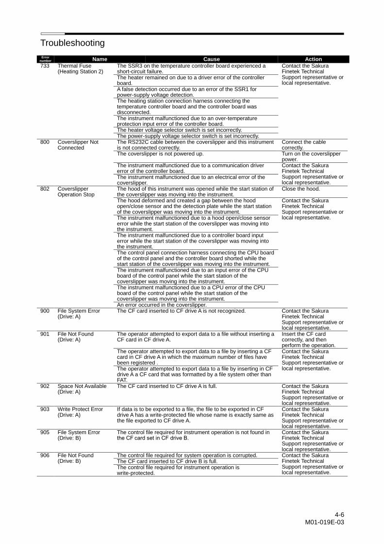
Troubleshooting
4-6 M01-019E-03
Error number Name Cause Action
733 Thermal Fuse (Heating Station 2)
The SSR3 on the temperature controller board experienced a short-circuit failure.
Contact the Sakura Finetek Technical Support representative or local representative.
The heater remained on due to a driver error of the controller board. A false detection occurred due to an error of the SSR1 for power-supply voltage detection. The heating station connection harness connecting the temperature controller board and the controller board was disconnected. The instrument malfunctioned due to an over-temperature protection input error of the controller board. The heater voltage selector switch is set incorrectly. The power-supply voltage selector switch is set incorrectly.
800 Coverslipper Not Connected
The RS232C cable between the coverslipper and this instrument is not connected correctly.
Connect the cable correctly.
The coverslipper is not powered up. Turn on the coverslipper power.
The instrument malfunctioned due to a communication driver error of the controller board.
Contact the Sakura Finetek Technical Support representative or local representative.
The instrument malfunctioned due to an electrical error of the coverslipper.
802 Coverslipper Operation Stop
The hood of this instrument was opened while the start station of the coverslipper was moving into the instrument.
Close the hood.
The hood deformed and created a gap between the hood open/close sensor and the detection plate while the start station of the coverslipper was moving into the instrument.
Contact the Sakura Finetek Technical Support representative or local representative. The instrument malfunctioned due to a hood open/close sensor
error while the start station of the coverslipper was moving into the instrument. The instrument malfunctioned due to a controller board input error while the start station of the coverslipper was moving into the instrument. The control panel connection harness connecting the CPU board of the control panel and the controller board shorted while the start station of the coverslipper was moving into the instrument. The instrument malfunctioned due to an input error of the CPU board of the control panel while the start station of the coverslipper was moving into the instrument. The instrument malfunctioned due to a CPU error of the CPU board of the control panel while the start station of the coverslipper was moving into the instrument. An error occurred in the coverslipper.
900 File System Error (Drive: A)
The CF card inserted to CF drive A is not recognized. Contact the Sakura Finetek Technical Support representative or local representative.
901 File Not Found (Drive: A)
The operator attempted to export data to a file without inserting a CF card in CF drive A.
Insert the CF card correctly, and then perform the operation.
The operator attempted to export data to a file by inserting a CF card in CF drive A in which the maximum number of files have been registered .
Contact the Sakura Finetek Technical Support representative or local representative. The operator attempted to export data to a file by inserting in CF
drive A a CF card that was formatted by a file system other than FAT.
902 Space Not Available (Drive: A)
The CF card inserted to CF drive A is full. Contact the Sakura Finetek Technical Support representative or local representative.
903 Write Protect Error (Drive: A)
If data is to be exported to a file, the file to be exported in CF drive A has a write-protected file whose name is exactly same as the file exported to CF drive A.
Contact the Sakura Finetek Technical Support representative or local representative.
905 File System Error (Drive: B)
The control file required for instrument operation is not found in the CF card set in CF drive B.
Contact the Sakura Finetek Technical Support representative or local representative.
906 File Not Found (Drive: B)
The control file required for system operation is corrupted. Contact the Sakura Finetek Technical Support representative or local representative.
The CF card inserted to CF drive B is full. The control file required for instrument operation is write-protected.
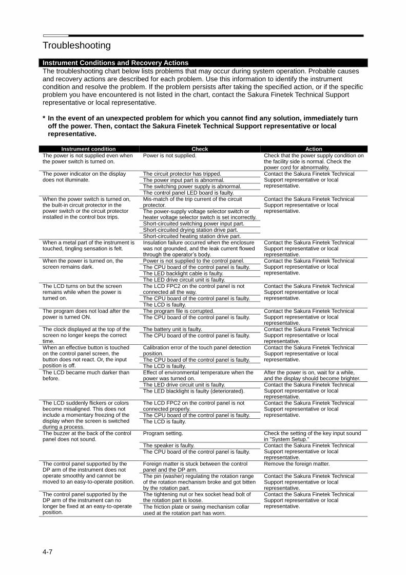
Troubleshooting
4-7
Instrument Conditions and Recovery Actions
The troubleshooting chart below lists problems that may occur during system operation. Probable causes and recovery actions are described for each problem. Use this information to identify the instrument condition and resolve the problem. If the problem persists after taking the specified action, or if the specific problem you have encountered is not listed in the chart, contact the Sakura Finetek Technical Support representative or local representative. * In the event of an unexpected problem for which you cannot find any solution, immediately turn
off the power. Then, contact the Sakura Finetek Technical Support representative or local representative.
Instrument condition Check Action
The power is not supplied even when the power switch is turned on.
Power is not supplied. Check that the power supply condition on the facility side is normal. Check the power cord for abnormality.
The power indicator on the display does not illuminate.
The circuit protector has tripped. Contact the Sakura Finetek Technical Support representative or local representative.
The power input part is abnormal. The switching power supply is abnormal. The control panel LED board is faulty.
When the power switch is turned on, the built-in circuit protector in the power switch or the circuit protector installed in the control box trips.
Mis-match of the trip current of the circuit protector.
Contact the Sakura Finetek Technical Support representative or local representative. The power-supply voltage selector switch or
heater voltage selector switch is set incorrectly. Short-circuited switching power input part. Short-circuited drying station drive part. Short-circuited heating station drive part.
When a metal part of the instrument is touched, tingling sensation is felt.
Insulation failure occurred when the enclosure was not grounded, and the leak current flowed through the operator’s body.
Contact the Sakura Finetek Technical Support representative or local representative.
When the power is turned on, the screen remains dark.
Power is not supplied to the control panel. Contact the Sakura Finetek Technical Support representative or local representative.
The CPU board of the control panel is faulty. The LED backlight cable is faulty. The LED drive circuit unit is faulty.
The LCD turns on but the screen remains while when the power is turned on.
The LCD FPC2 on the control panel is not connected all the way.
Contact the Sakura Finetek Technical Support representative or local representative. The CPU board of the control panel is faulty.
The LCD is faulty. The program does not load after the power is turned ON.
The program file is corrupted. Contact the Sakura Finetek Technical Support representative or local representative.
The CPU board of the control panel is faulty.
The clock displayed at the top of the screen no longer keeps the correct time.
The battery unit is faulty. Contact the Sakura Finetek Technical Support representative or local representative.
The CPU board of the control panel is faulty.
When an effective button is touched on the control panel screen, the button does not react. Or, the input position is off.
Calibration error of the touch panel detection position.
Contact the Sakura Finetek Technical Support representative or local representative. The CPU board of the control panel is faulty.
The LCD is faulty. The LCD became much darker than before.
Effect of environmental temperature when the power was turned on.
After the power is on, wait for a while, and the display should become brighter.
The LED drive circuit unit is faulty. Contact the Sakura Finetek Technical Support representative or local representative.
The LED blacklight is faulty (deteriorated).
The LCD suddenly flickers or colors become misaligned. This does not include a momentary freezing of the display when the screen is switched during a process.
The LCD FPC2 on the control panel is not connected properly.
Contact the Sakura Finetek Technical Support representative or local representative. The CPU board of the control panel is faulty.
The LCD is faulty.
The buzzer at the back of the control panel does not sound.
Program setting. Check the setting of the key input sound in "System Setup."
The speaker is faulty. Contact the Sakura Finetek Technical Support representative or local representative.
The CPU board of the control panel is faulty.
The control panel supported by the DP arm of the instrument does not operate smoothly and cannot be moved to an easy-to-operate position.
Foreign matter is stuck between the control panel and the DP arm.
Remove the foreign matter.
The pin (washer) regulating the rotation range of the rotation mechanism broke and got bitten by the rotation part.
Contact the Sakura Finetek Technical Support representative or local representative.
The control panel supported by the DP arm of the instrument can no longer be fixed at an easy-to-operate position.
The tightening nut or hex socket head bolt of the rotation part is loose.
Contact the Sakura Finetek Technical Support representative or local representative. The friction plate or swing mechanism collar
used at the rotation part has worn.
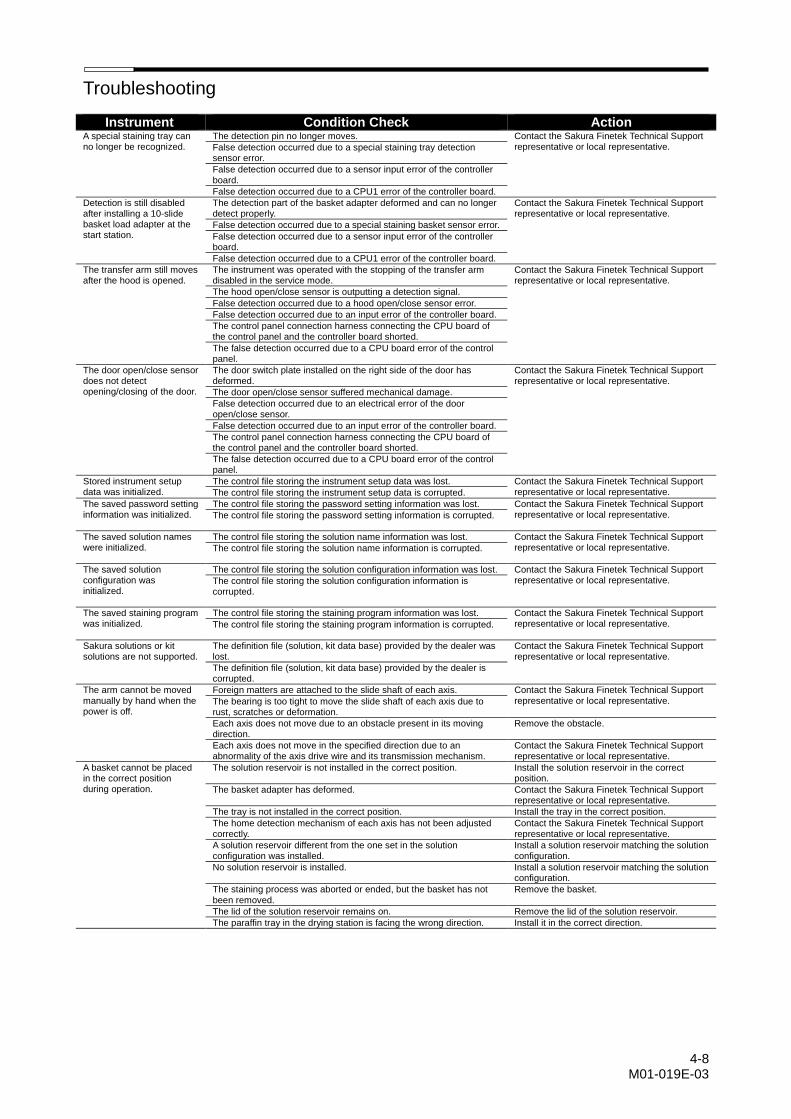
Troubleshooting
4-8 M01-019E-03
Instrument Condition Check Action A special staining tray can no longer be recognized.
The detection pin no longer moves. Contact the Sakura Finetek Technical Support representative or local representative. False detection occurred due to a special staining tray detection
sensor error.
False detection occurred due to a sensor input error of the controller board.
False detection occurred due to a CPU1 error of the controller board.
Detection is still disabled after installing a 10-slide basket load adapter at the start station.
The detection part of the basket adapter deformed and can no longer detect properly.
Contact the Sakura Finetek Technical Support representative or local representative.
False detection occurred due to a special staining basket sensor error.
False detection occurred due to a sensor input error of the controller board.
False detection occurred due to a CPU1 error of the controller board.
The transfer arm still moves after the hood is opened.
The instrument was operated with the stopping of the transfer arm disabled in the service mode.
Contact the Sakura Finetek Technical Support representative or local representative.
The hood open/close sensor is outputting a detection signal.
False detection occurred due to a hood open/close sensor error.
False detection occurred due to an input error of the controller board.
The control panel connection harness connecting the CPU board of the control panel and the controller board shorted.
The false detection occurred due to a CPU board error of the control panel.
The door open/close sensor does not detect opening/closing of the door.
The door switch plate installed on the right side of the door has deformed.
Contact the Sakura Finetek Technical Support representative or local representative.
The door open/close sensor suffered mechanical damage.
False detection occurred due to an electrical error of the door open/close sensor.
False detection occurred due to an input error of the controller board.
The control panel connection harness connecting the CPU board of the control panel and the controller board shorted.
The false detection occurred due to a CPU board error of the control panel.
Stored instrument setup data was initialized.
The control file storing the instrument setup data was lost. Contact the Sakura Finetek Technical Support representative or local representative. The control file storing the instrument setup data is corrupted.
The saved password setting information was initialized.
The control file storing the password setting information was lost. Contact the Sakura Finetek Technical Support representative or local representative. The control file storing the password setting information is corrupted.
The saved solution names were initialized.
The control file storing the solution name information was lost. Contact the Sakura Finetek Technical Support representative or local representative. The control file storing the solution name information is corrupted.
The saved solution configuration was initialized.
The control file storing the solution configuration information was lost. Contact the Sakura Finetek Technical Support representative or local representative. The control file storing the solution configuration information is
corrupted.
The saved staining program was initialized.
The control file storing the staining program information was lost. Contact the Sakura Finetek Technical Support representative or local representative. The control file storing the staining program information is corrupted.
Sakura solutions or kit solutions are not supported.
The definition file (solution, kit data base) provided by the dealer was lost.
Contact the Sakura Finetek Technical Support representative or local representative.
The definition file (solution, kit data base) provided by the dealer is corrupted.
The arm cannot be moved manually by hand when the power is off.
Foreign matters are attached to the slide shaft of each axis. Contact the Sakura Finetek Technical Support representative or local representative. The bearing is too tight to move the slide shaft of each axis due to
rust, scratches or deformation.
Each axis does not move due to an obstacle present in its moving direction.
Remove the obstacle.
Each axis does not move in the specified direction due to an abnormality of the axis drive wire and its transmission mechanism.
Contact the Sakura Finetek Technical Support representative or local representative.
A basket cannot be placed in the correct position during operation.
The solution reservoir is not installed in the correct position. Install the solution reservoir in the correct position.
The basket adapter has deformed. Contact the Sakura Finetek Technical Support representative or local representative.
The tray is not installed in the correct position. Install the tray in the correct position.
The home detection mechanism of each axis has not been adjusted correctly.
Contact the Sakura Finetek Technical Support representative or local representative.
A solution reservoir different from the one set in the solution configuration was installed.
Install a solution reservoir matching the solution configuration.
No solution reservoir is installed. Install a solution reservoir matching the solution configuration.
The staining process was aborted or ended, but the basket has not been removed.
Remove the basket.
The lid of the solution reservoir remains on. Remove the lid of the solution reservoir.
The paraffin tray in the drying station is facing the wrong direction. Install it in the correct direction.

Troubleshooting
4-9
Instrument Condition Check Action The basket was placed in the reservoir, but does not come off from the adapter.
The solution reservoir is not installed in the correct position. Install the solution reservoir in the correct position.
The basket adapter has deformed. Contact the Sakura Finetek Technical Support representative or local representative. The home detection mechanism of each axis has not been adjusted
correctly.
When the facility is operating under the conditions within the use environment of the instrument, water is not supplied by the water supply operation.
The water supply plug on the facility side, or the flow rate adjustment valve in the instrument, is closed.
Open the flow rate adjustment valve.
Setting of the water flow time under control is too short. Contact the Sakura Finetek Technical Support representative or local representative.
The strainer is clogged. Clean the strainer.
The seat of the check valve is stuck (built-in check valve in the pressure relief valve or the check valve before the water supply manifold).
Contact the Sakura Finetek Technical Support representative or local representative.
The water supply solenoid valve is faulty.
The valve seat of the vacuum breaker is stuck or leaking.
The float switch has actuated (error code: 90).
The instrument power is off, but water is leaking from the water supply nozzle.
Contaminants entered the water supply solenoid valve seat. Contact the Sakura Finetek Technical Support representative or local representative. The water supply solenoid valve is damaged.
When the facility was operating under the conditions within the use environment of the instrument, the water level reached by supplying water to the instrument is lower than before.
The flow rate adjustment valve is clogged. Use the flow rate adjustment valve to adjust the amount of water supplied.
The strainer is clogged. Clean the strainer.
The O-ring of the water supply nozzle is damaged. Contact the Sakura Finetek Technical Support representative or local representative. The wash reservoir is damaged.
The wash reservoir is not installed properly.
When the facility was operating under the conditions within the use environment of the instrument, the water level reached by supplying water to the instrument is more than before.
The open angle of the flow rate adjustment valve was changed. Use the flow rate adjustment valve to adjust the amount of water supplied.
The pressure relief valve is damaged. Contact the Sakura Finetek Technical Support representative or local representative.
The water supply capacity on the facility side has changed. Use the flow rate adjustment valve to adjust the amount of water supplied.
Water is leaking from the instrument due to a problem with water supply or drain.
A component of the water supply part is damaged. Contact the Sakura Finetek Technical Support representative or local representative. The component connection point at the water supply part is leaking
water.
The connection of the drain hose is loose or clogged.
The sink is leaking water.
The solution odor is leaked from the instrument when the instrument is operating.
No fume cartridge is set. Install a fume cartridge.
The fume cartridge was set without unpacking it. Unpack the fume cartridge.
The fume cartridge is not installed properly. Install the fume cartridge correctly.
The fume cartridge has reached its life. Replace the fume cartridge.
The exhaust fan stopped. Contact the Sakura Finetek Technical Support representative or local representative.
The air inlet port in the system was blocked. Check the air inlet port for foreign matters.
Each gasket of the fume control unit deteriorated. Contact the Sakura Finetek Technical Support representative or local representative.
The exhaust outlet port is blocked. Do not block the exhaust outlet port.
When connecting the exhaust duct, it is not connected correctly. Contact the Sakura Finetek Technical Support representative or local representative. The exhaust duct is too long.
The exhaust duct was crushed.
The exhaust system on the facility side is not operating. Check the exhaust system on the facility side.
Solution odor leaks from the instrument when the operation is stopped with solution still in the instrument.
The door is open. Close the door.
The hood is open Close the hood.
There is no lid on the solution reservoir. Put the lid on the solution reservoir.
The hood does not open smoothly.
The hood was pushed open at an angle. Contact the Sakura Finetek Technical Support representative or local representative.
The hood (top plate) is bitten. Check for foreign matters and remove them, if found.
The rotary damper and rack are bitten or damaged. Check for foreign matters and remove them, if found.
The roller pack is bitten or damaged. Contact the Sakura Finetek Technical Support representative or local representative. The spring stay is damaged.
The hood does not close smoothly or fully.
The hood closes at an angle or does not close fully. Contact the Sakura Finetek Technical Support representative or local representative. The hood is distorted.
The hood (top plate) is bitten. Check for foreign matters and remove them, if found.
The rotary damper and rack are bitten or damaged. Contact the Sakura Finetek Technical Support representative or local representative. The roller pack is bitten or damaged.
The spring stay is damaged.
The hood stay adjustment is inappropriate.
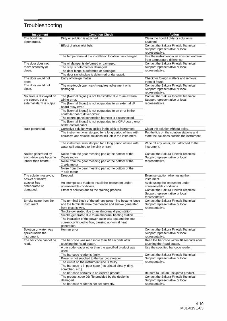
Troubleshooting
4-10 M01-019E-03
Instrument Condition Check Action
The hood has deteriorated.
Dirty or solution is attached. Clean the hood if dirty or solution is attached.
Effect of ultraviolet light. Contact the Sakura Finetek Technical Support representative or local representative.
The temperature at the installation location has changed. Use the instrument in an environment free from temperature difference.
The door does not move smoothly or close.
The oil damper is deformed or damaged. Contact the Sakura Finetek Technical Support representative or local representative.
The stay is deformed or damaged.
The door hinge is deformed or damaged.
The door switch plate is deformed or damaged.
The door would not open. The door would not close.
Entry of foreign matter Check for foreign matters and remove them, if found.
The one-touch open catch requires adjustment or is damaged.
Contact the Sakura Finetek Technical Support representative or local representative.
No error is displayed on the screen, but an external alarm is output.
The [Normal Signal] is not transmitted due to an external wiring error.
Contact the Sakura Finetek Technical Support representative or local representative. The [Normal Signal] is not output due to an external I/F
board relay error.
The [Normal Signal] is not output due to an error in the controller board driver circuit.
The control panel connection harness is disconnected.
The [Normal Signal] is not output due to a CPU board error of the control panel.
Rust generated. Corrosive solution was spilled in the sink or instrument. Clean the solution without delay.
The instrument was stopped for a long period of time with corrosive and volatile solutions still left in the instrument.
Put the lids on the solution stations and store the solutions outside the instrument.
The instrument was stopped for a long period of time with water still attached to the sink or tray.
Wipe off any water, etc., attached to the instrument.
Noises generated by each drive axis became louder than before.
Noise from the gear meshing part at the bottom of the Z-axis motor
Contact the Sakura Finetek Technical Support representative or local representative. Noise from the gear meshing part at the bottom of the
X-axis motor
Noise from the gear meshing part at the bottom of the Y-axis motor
The solution reservoir, basket or basket adapter has deteriorated or damaged.
Dropped. Exercise caution when using the instrument.
An attempt was made to install the instrument under unreasonable conditions.
Avoid using the instrument under unreasonable conditions.
Effect of solution due to the staining process. Contact the Sakura Finetek Technical Support representative or local representative.
Smoke came from the instrument.
The terminal block of the primary power line became loose and the terminals were overheated and smoke generated from electric wire.
Contact the Sakura Finetek Technical Support representative or local representative.
Smoke generated due to an abnormal drying station.
Smoke generated due to an abnormal heating station.
The insulation of the power cable was lost and the leak current continued to flow, causing abnormal heat generation.
Solution or water was spilled inside the instrument.
Human error Contact the Sakura Finetek Technical Support representative or local representative.
The bar code cannot be read.
The bar code was read more than 10 seconds after touching the Read button.
Read the bar code within 10 seconds after touching the Read button.
A bar code reader other than the specified product was used.
Use the specified bar code reader.
The bar code reader is faulty. Contact the Sakura Finetek Technical Support representative or local representative.
Power is not supplied to the bar code reader.
The circuit on the instrument side is faulty.
The bar code is in poor state (not printed clearly, dirty, scratched, etc.)
The bar code pertains to an expired product. Be sure to use an unexpired product.
The product code DB file provided by the dealer is damaged.
Contact the Sakura Finetek Technical Support representative or local representative. The bar code reader is not set correctly.