prisma ipm system l catalogue 2011
TRANSCRIPT
8/15/2019 Prisma iPM System L Catalogue 2011
http://slidepdf.com/reader/full/prisma-ipm-system-l-catalogue-2011 1/128
Prisma iPMsystem L
Catalogue2011
Wall mounted switchboards up to 630A
Low Voltage
8/15/2019 Prisma iPM System L Catalogue 2011
http://slidepdf.com/reader/full/prisma-ipm-system-l-catalogue-2011 2/128
Assembling recommendations F-2
Assembling tips F-8
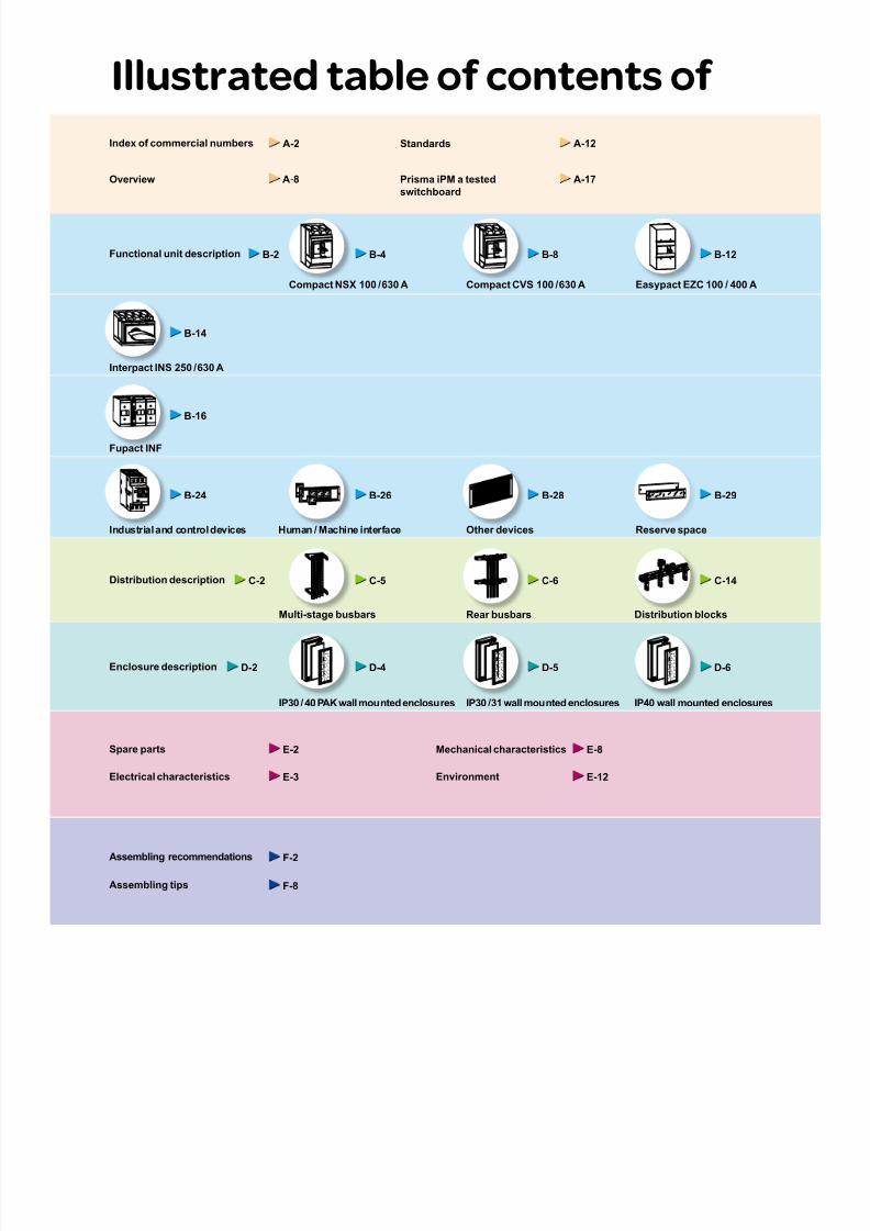
Illustrated table of contents of
Compact CVS 100 / 630 ACompact NSX 100 / 630 A
Fupact INF
Interpact INS 250 / 630 A
Industrial and control devices Human / Machine interface
Easypact EZC 100 / 400 A
Multi-stage busbars Rear busbars Distribution blocks
IP40 wall mounted enclosuresIP30 / 31 wall mounted enclosuresIP30 / 40 PAK wall mounted enclosures
Functional unit description
Distribution description
Enclosure description
Standards A-12
Prisma iPM a tested
switchboard
A-17Overview A-8
Index of commercial numbers A-2
B-2 B-4 B-8 B-12
C-2 C-5 C-6
Electrical characteristics E-3
Mechanical characteristics E-8
Environment E-12
D-2 D-4 D-5 D-6
Spare parts E-2
B-14
B-16
B-24 B-26
Other devices
B-28
Reserve space
B-29
C-14

8/15/2019 Prisma iPM System L Catalogue 2011
http://slidepdf.com/reader/full/prisma-ipm-system-l-catalogue-2011 3/128
Multi 9 modular devices NG125 modular device
Accessories Partitioning
IP30 / 31 / 40 / 54 enclosure accessoriesIP54 wall mounted enclosures
Prisma iPM system L
PAK and wall mountedenclosures
Circuit breakers
Fusegear
Switch-disconnectors
Other
Distribution
D i s t r i b u
t i o n
F u n c t i o n a l u n i t s
E n c l o s u r e s
I n d e x a n d
p r
e s e n t a t i o n
C h a r a c t e r i s t i c s
R e c o m m e n d a t i o n s
B-20
Functional units accessories
B-30
C-16 C-19
D-8
B-20
Wall mounted system L A-18
Tools and services A-22
Commercial reference A-24
D-7 D-10
Dimensions

8/15/2019 Prisma iPM System L Catalogue 2011
http://slidepdf.com/reader/full/prisma-ipm-system-l-catalogue-2011 4/128 A-4
8/15/2019 Prisma iPM System L Catalogue 2011
http://slidepdf.com/reader/full/prisma-ipm-system-l-catalogue-2011 5/128 A-1
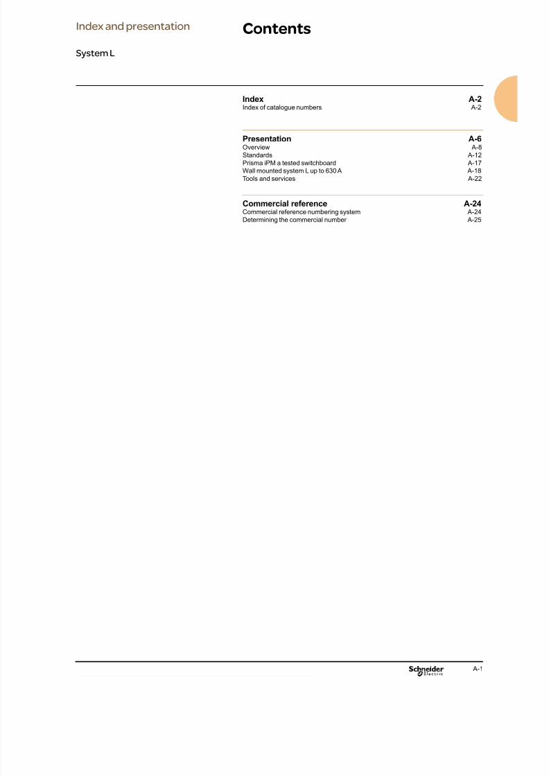
Contents
Index A-2Index of catalogue numbers A-2
Presentation A-6Overview A-8
Standards A-12
Prisma iPM a tested switchboard A-17
Wall mounted system L up to 630 A A-18
Tools and services A-22
Commercial reference A-24Commercial reference numbering system A-24
Determining the commercial number A-25
Index and presentation
System L

8/15/2019 Prisma iPM System L Catalogue 2011
http://slidepdf.com/reader/full/prisma-ipm-system-l-catalogue-2011 6/128 A-2
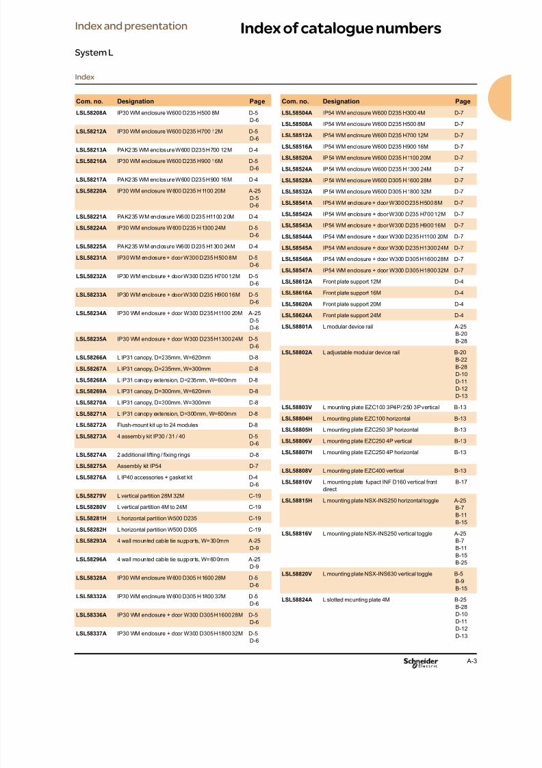
Index of catalogue numbers
Index
Index and presentation
System L
Com. no. Designation Page
03180 20 M4 clip-nuts for slotted mounting plates B-28
03181 20 M5 clip-nuts for slotted mounting plates B-28
03182 20 M6 clip-nuts for slotted mounting plates B-28
03195 4 M6 hexagonal spacers, H=9mm B-30
03196 4 M6 hexagonal spacers, H=23mm B-30
03197 4 M6 hexagonal spacers, H=55mm B-30
03581 2 universal angle brackets B-30
04031 Polybloc distribut ion block, 1P, 160A C-15
04033 Polybloc distribut ion block, 3P, 250A C-15
04034 Polybloc distribut ion block, 4P, 250A C-15
04045 Distribloc 125A B-21
B-23
C-15
04171 4 bars with threaded holes, 160A, L=1400mm C-12
C-13
04172 4 bars with threaded holes, 250A, L=1400mm A-25
C-12
C-13
04173 4 bars with threaded holes, 400A, L=1400mm C-12
C-13
04174 4 bars with threaded holes, 630A, L=1400mm C-12
C-13
04195 40 M6x16mm screws for bars with threaded holes,
less than 630A
A-25
C-13
C-18
04197 Busbar power supply barrier, 630A A-25C-13
04226 Modular device rail, L=1600mm B-25
B-28
04239 12 horizontal cable straps A-25
B-21
B-23
C-17
04243 4 covers for horizontal cable straps A-25
B-21
B-23
C-17
04255 12 horizontal trunking supports B-21
B-23
C-18
04742 Insulated exible bar 20x2mm, L=1800mm C-16
04743 Insulated exible bar 20x3mm, L=1800mm C-16
04751 Insulated exible bar 32x5mm, L=1800mm C-16
04753 Insulated exible bar 32x8mm, L=1800mm C-16
08903 12 adhesive label holders, H=24mm, W=432mm B-31
08913 12 clip-on labels, 18x35mm B-31
08940 Barrel lock no. 405 D-9
08945 DIN double bar insert D-9
08946 Screwdriver slot insert D-9
08963 Adhesive drawing holder D-9
LSL58033A Door spare parts for system L E-2
LSL58104A IP30-IP54 plain door W600 H300 4M D-5
D-6
D-7
LSL58108A Plain door W600 H500 8M D-5
Com. no. Designation Page
LSL58112A Plain door W600 H700 12M D-4
D-5
LSL58116A Plain door W600 H900 16M D-4
D-5
LSL58120A Plain door W600 H1100 20M D-4
D-5
LSL58124A Plain door W600 H1300 24M D-4
D-5
LSL58128A Plain door W600 H1600 28M D-5
LSL58132A Plain door W600 H1800 32M D-5
LSL58149A IP54 plain door W600 H500 8M D-6
D-7
LSL58150A IP54 plain door W600 H700 12M D-4
D-6
D-7
LSL58151A IP54 plain door W600 H900 16M D-4
D-6
D-7
LSL58152A IP54 plain door W600 H1100 20M D-4
D-6
D-7
LSL58153A IP54 plain door W600 H1300 24M D-4
D-6
D-7
LSL58154A IP54 plain door W600 H1600 28M D-6
D-7
LSL58155A IP54 plain door W600 H1800 32M D-6
D-7LSL58157T IP54 transparent door W600 H900 16M D-4
D-6
D-7
LSL58158T IP54 transparent door W600 H1100 20M D-4
D-6
D-7
LSL58159T IP54 transparent door W600 H1300 24M D-4
D-6
D-7
LSL58160T IP54 transparent door W600 H500 8M D-7
LSL58161T IP54 transparent door W600 H700 12M D-7
LSL58162T Transparent door W600 H500 8M D-5
D-6
LSL58163T Transparent door W600 H700 12M D-4
D-5
D-6
LSL58164T Transparent door W600 H900 16M D-4
D-5
LSL58165T Transparent door W600 H1100 20M A-25
D-4
D-5
LSL58166T Transparent door W600 H1300 24M D-4
D-5
LSL58167T Transparent door W600 H1600 28M D-5
D-6
LSL58168T Transparent door W600 H1800 32M D-5
D-6
LSL58169T IP54 transparent door W600 H1600 28M D-7
LSL58170T IP54 transparent door W600 H1800 32M D-7
LSL58204A IP30 WM enclosure W600 D235 H300 4M D-5
D-6
8/15/2019 Prisma iPM System L Catalogue 2011
http://slidepdf.com/reader/full/prisma-ipm-system-l-catalogue-2011 7/128 A-3
Index of catalogue numbers
Index
Index and presentation
System L
Com. no. Designation Page
LSL58208A IP30 WM enclosure W600 D235 H500 8M D-5
D-6
LSL58212A IP30 WM enclosure W600 D235 H700 12M D-5
D-6
LSL58213A PAK235 WM enclosure W600 D235 H700 12M D-4
LSL58216A IP30 WM enclosure W600 D235 H900 16M D-5
D-6
LSL58217A PAK235 WM enclosure W600 D235 H900 16M D-4
LSL58220A IP30 WM enclosure W600 D235 H1100 20M A-25
D-5
D-6
LSL58221A PAK235 WM enclosure W600 D235 H1100 20M D-4
LSL58224A IP30 WM enclosure W600 D235 H1300 24M D-5
D-6
LSL58225A PAK235 WM enclosure W600 D235 H1300 24M D-4
LSL58231A IP30 WM enclosure + door W300 D235 H500 8M D-5
D-6
LSL58232A IP30 WM enclosure + door W300 D235 H700 12M D-5
D-6
LSL58233A IP30 WM enclosure + door W300 D235 H900 16M D-5
D-6
LSL58234A IP30 WM enclosure + door W300 D235 H1100 20M A-25
D-5
D-6
LSL58235A IP30 WM enclosure + door W300 D235 H1300 24M D-5
D-6
LSL58266A L IP31 canopy, D=235mm, W=620mm D-8
LSL58267A L IP31 canopy, D=235mm, W=300mm D-8
LSL58268A L IP31 canopy extension, D=235mm, W=600mm D-8
LSL58269A L IP31 canopy, D=300mm, W=620mm D-8
LSL58270A L IP31 canopy, D=300mm, W=300mm D-8
LSL58271A L IP31 canopy extension, D=300mm, W=600mm D-8
LSL58272A Flush-mount kit up to 24 modules D-8
LSL58273A 4 assembly kit IP30 / 31 / 40 D-5
D-6
LSL58274A 2 additional lifting / xing rings D-8
LSL58275A Assembly kit IP54 D-7
LSL58276A L IP40 accessories + gasket kit D-4D-6
LSL58279V L vertical partition 28M 32M C-19
LSL58280V L vertical partition 4M to 24M C-19
LSL58281H L horizontal partition W500 D235 C-19
LSL58282H L horizontal partition W500 D305 C-19
LSL58293A 4 wall mounted cable tie supports, W=300mm A-25
D-9
LSL58296A 4 wall mounted cable tie supports, W=600mm A-25
D-9
LSL58328A IP30 WM enclosure W600 D305 H1600 28M D-5
D-6
LSL58332A IP30 WM enclosure W600 D305 H1800 32M D-5
D-6
LSL58336A IP30 WM enclosure + door W300 D305 H1600 28M D-5
D-6
LSL58337A IP30 WM enclosure + door W300 D305 H1800 32M D-5
D-6
Com. no. Designation Page
LSL58504A IP54 WM enclosure W600 D235 H300 4M D-7
LSL58508A IP54 WM enclosure W600 D235 H500 8M D-7
LSL58512A IP54 WM enclosure W600 D235 H700 12M D-7
LSL58516A IP54 WM enclosure W600 D235 H900 16M D-7
LSL58520A IP54 WM enclosure W600 D235 H1100 20M D-7
LSL58524A IP54 WM enclosure W600 D235 H1300 24M D-7
LSL58528A IP54 WM enclosure W600 D305 H1600 28M D-7
LSL58532A IP54 WM enclosure W600 D305 H1800 32M D-7
LSL58541A IP54 WM enclosure + door W300 D235 H500 8M D-7
LSL58542A IP54 WM enclosure + door W300 D235 H700 12M D-7
LSL58543A IP54 WM enclosure + door W300 D235 H900 16M D-7
LSL58544A IP54 WM enclosure + door W300 D235 H1100 20M D-7
LSL58545A IP54 WM enclosure + door W300 D235 H1300 24M D-7
LSL58546A IP54 WM enclosure + door W300 D305 H1600 28M D-7
LSL58547A IP54 WM enclosure + door W300 D305 H1800 32M D-7
LSL58612A Front plate support 12M D-4
LSL58616A Front plate support 16M D-4
LSL58620A Front plate support 20M D-4
LSL58624A Front plate support 24M D-4
LSL58801A L modular device rail A-25
B-20
B-28
LSL58802A L adjustable modular device rail B-20
B-22B-28
D-10
D-11
D-12
D-13
LSL58803V L mounting plate EZC100 3P4P / 250 3P vertical B-13
LSL58804H L mounting plate EZC100 horizontal B-13
LSL58805H L mounting plate EZC250 3P horizontal B-13
LSL58806V L mounting plate EZC250 4P vertical B-13
LSL58807H L mounting plate EZC250 4P horizontal B-13
LSL58808V L mounting plate EZC400 vertical B-13
LSL58810V L mounting plate fupact INF D160 vertical front
direct
B-17
LSL58815H L mounting plate NSX-INS250 horizontal toggle A-25
B-7
B-11
B-15
LSL58816V L mounting plate NSX-INS250 vertical toggle A-25
B-7
B-11
B-15
B-25
LSL58820V L mounting plate NSX-INS630 vertical toggle B-5
B-9
B-15
LSL58824A L slotted mounting plate 4M B-25B-28
D-10
D-11
D-12
D-13

8/15/2019 Prisma iPM System L Catalogue 2011
http://slidepdf.com/reader/full/prisma-ipm-system-l-catalogue-2011 8/128 A-4
Index
Index of catalogue numbersIndex and presentation
System L
Com. no. Designation Page
LSL58825A L slotted mounting plate 12M B-25
B-28D-10
D-11
D-12
D-13
LSL58826A L plain mounting plate 4M B-28
D-10
D-11
D-12
D-13
LSL58827A L plain mounting plate 12M B-28
D-10
D-11
D-12
D-13
LSX58030A 20 front plate screws+nuts E-2
LSX58031A Prisma iPM spare parts handle E-2
LSX58052A Multiclip 200A 2P B-21C-15
LSX58053A Multiclip 200A 3P A-25
B-21
B-23
C-15
LSX58054A Multiclip 200A 4P B-21
B-23
C-15
LSX58070A Cu earth / neutral bar 24M A-25
C-17
LSX58080A Rear busbars support C-13
LSX58081A Rear busbar barrier C-13
LSX58082A Multi-stage busbars support A-25
C-13
LSX58621A Blanking strip modular device L1000 B-21
B-23
B-28
B-30
LSX58751A Blanking strip CVS/NSX250, L = 147 mm B-7
B-11
B-25
B-30
LSX58752A Blanking strip EZC250 L1000 B-13
B-30
LSX58776A Front plate hinge kit B-25
B-30
LSX58777A 4 front plate lead-sealable screws B-30
LSX58883A Front plate modular device 3M B-21
B-25
B-28
LSX58884A Front plate modular device 4M A-25
B-21
B-23
B-25
B-28
LSX58885A Front plate modular device 5M B-21B-23
B-28
LSX58886V Front plate EZC100 vertical B-13
LSX58887H Front plate EZC100 horizontal B-13
Com. no. Designation Page
LSX58888H Front plate EZC250 3P horizontal B-13
LSX58889V Front plate 3 / 4 EZC250 vertical B-13
LSX58890H Front plate EZC250 4P horizontal B-13
LSX58892V Front plate EZC400 3P vertical B-13
LSX58895V Front p late 4 FUPACT INFD32 / 40 3P vert ical B-17
LSX58896V Front plate 3 FUPACT INFD63 3P vertical B-17
LSX58897V Front plate 2 FUPACT INFD100 / 160 3P vertical B-17
LSX58900H Front plate CVS250 horizontal toggle A-25
B-11
LSX58901H Front plate INS250 horizontal B-15
LSX58902V Front plate 3 / 4 CVS-NSX-INS250 vertical toggle B-7
B-11
B-25
LSX58903V Front plate 3 / 4 CVS-NSX-INS250 vertical toggle B-7
B-11
LSX58904H Front plate NSX250 horizontal B-7
LSX58905V Front plate INS250 vertical A-25
B-15
LSX58911V Front plate CVS630 vertical toggle B-9
LSX58912V Front plate CVS630 vertical vigi B-9
LSX58913V Front plate NSX630 vertical B-5
LSX58914V Front plate INS630 vertical B-15
LSX58921V Front plate NSX630 vertical vigi B-5
LSX58931A Plain front plate 1M A-25
B-5
B-7
B-11
B-13
B-15
B-21
B-23
B-25
B-29
LSX58932A Plain front plate 2M A-25
B-5
B-7
B-9
B-11
B-13
B-15
B-17
B-29
LSX58933A Plain front plate 3M B-5
B-9
B-15
B-25
B-29
LSX58934A Plain front plate 4M B-5
B-9
B-25
B-29
LSX58936A Plain front plate 6M B-25
B-29
C-13
LSX58955A Metal front plate with cut-outs, 3 modules
(for four 96 x 96 mm devices)
B-27
8/15/2019 Prisma iPM System L Catalogue 2011
http://slidepdf.com/reader/full/prisma-ipm-system-l-catalogue-2011 9/128 A-5
Index
Index of catalogue numbersIndex and presentation
System L
Com. no. Designation Page
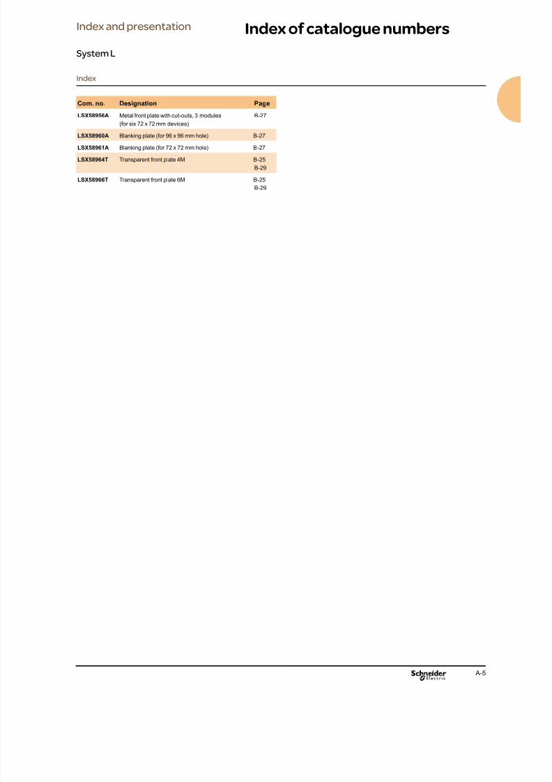
LSX58956A Metal front plate with cut-outs, 3 modules
(for six 72 x 72 mm devices)
B-27
LSX58960A Blanking plate (for 96 x 96 mm hole) B-27
LSX58961A Blanking plate (for 72 x 72 mm hole) B-27
LSX58964T Transparent front plate 4M B-25
B-29
LSX58966T Transparent front plate 6M B-25
B-29

8/15/2019 Prisma iPM System L Catalogue 2011
http://slidepdf.com/reader/full/prisma-ipm-system-l-catalogue-2011 10/128 A-6
Ensuring the dependability
of electrical installations
of tertiary and industrial
buildings: continuity of
service and safety of life
and property.
Prisma iPM, a dependable,
simple, innovative solution
for LV electrical distribution
and control switchboards.
Let’s pool ourenergies for buildingdependability

8/15/2019 Prisma iPM System L Catalogue 2011
http://slidepdf.com/reader/full/prisma-ipm-system-l-catalogue-2011 11/128 A-7
Seize the Prisma iPM opportunity when assembling switchboards
that are optimised, tested and compliant with the IEC 61439-1 standard.
Prisma iPM is a prefabricated, modular solution unique in the market,
that is reliable and upgradeable.
You control your costs and deadlines. Buildings run perfectly.
Users work efciently and safely.
100% dependable
switchboards
Make the most of your energy

8/15/2019 Prisma iPM System L Catalogue 2011
http://slidepdf.com/reader/full/prisma-ipm-system-l-catalogue-2011 12/128 A-8
As building market professionals, you are faced with growing demands
for electrical installation continuity of service, safety of life and property
and deadline and cost control.
Let’s develop installationdependability
8/15/2019 Prisma iPM System L Catalogue 2011
http://slidepdf.com/reader/full/prisma-ipm-system-l-catalogue-2011 13/128 A-9
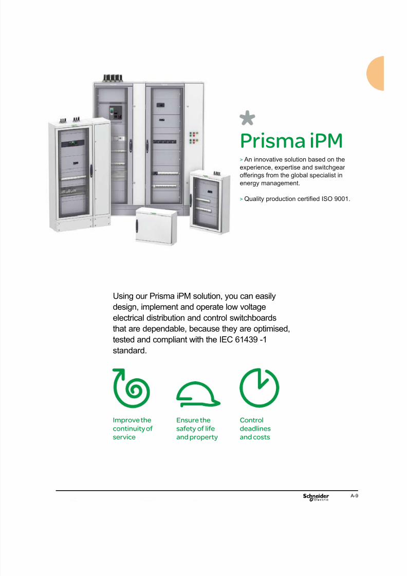
Using our Prisma iPM solution, you can easily
design, implement and operate low voltage
electrical distribution and control switchboards
that are dependable, because they are optimised,
tested and compliant with the IEC 61439 -1
standard.
Improve the
continuity of
service
Ensure the
safety of life
and property
Control
deadlines
and costs
Prisma iPM> An innovative solution based on the
experience, expertise and switchgear
offerings from the global specialist in
energy management.
> Quality production certied ISO 9001.
8/15/2019 Prisma iPM System L Catalogue 2011
http://slidepdf.com/reader/full/prisma-ipm-system-l-catalogue-2011 14/128 A-10
2
3
1
4
5
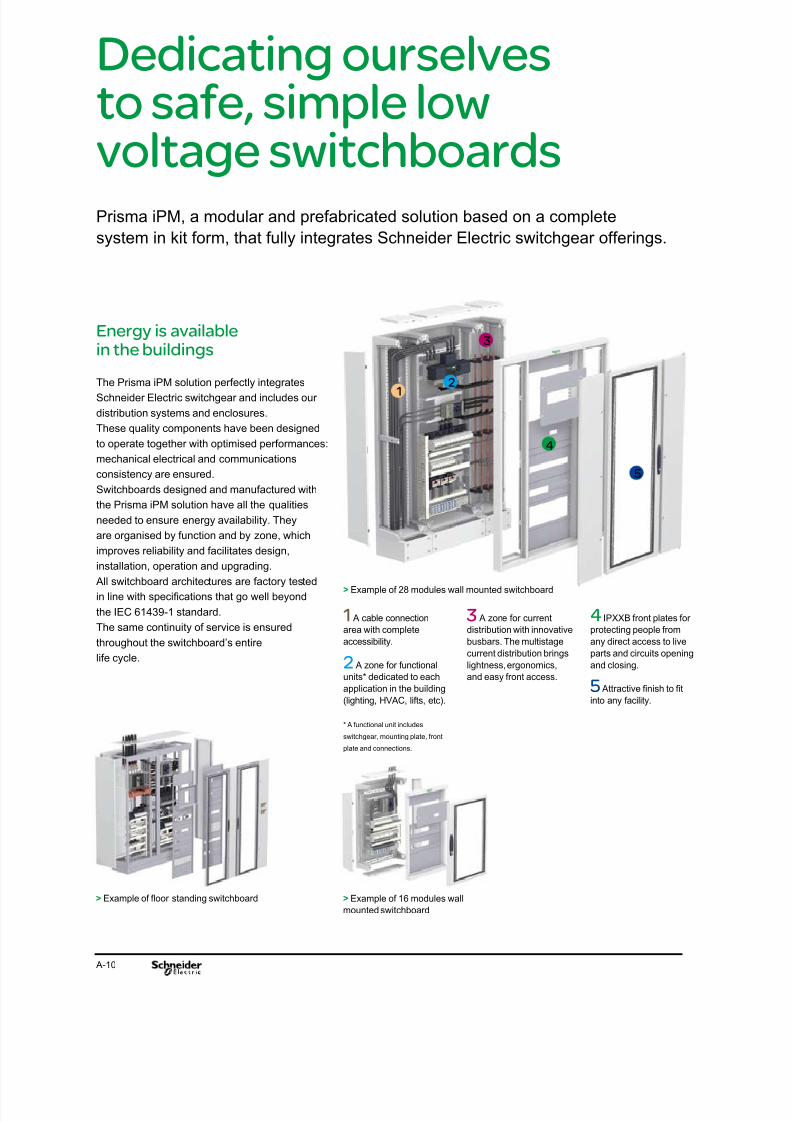
Dedicating ourselvesto safe, simple low
voltage switchboardsPrisma iPM, a modular and prefabricated solution based on a complete
system in kit form, that fully integrates Schneider Electric switchgear offerings.
1 A cable connection
area with complete
accessibility.
2 A zone for functional
units* dedicated to each
application in the building
(lighting, HVAC, lifts, etc).
* A functional unit includes
switchgear, mounting plate, front
plate and connections.
3 A zone for current
distribution with innovative
busbars. The multistage
current distribution brings
lightness, ergonomics,
and easy front access.
4 IPXXB front plates for
protecting people from
any direct access to live
parts and circuits opening
and closing.
5 Attractive nish to t
into any facility.
> Example of 28 modules wall mounted switchboard
Energy is available
in the buildings
The Prisma iPM solution perfectly integrates
Schneider Electric switchgear and includes our
distribution systems and enclosures.
These quality components have been designed
to operate together with optimised performances:
mechanical electrical and communications
consistency are ensured.
Switchboards designed and manufactured with
the Prisma iPM solution have all the qualities
needed to ensure energy availability. Theyare organised by function and by zone, which
improves reliability and facilitates design,
installation, operation and upgrading.
All switchboard architectures are factory tested
in line with specications that go well beyond
the IEC 61439-1 standard.
The same continuity of service is ensured
throughout the switchboard’s entire
life cycle.
> Example of 16 modules wall
mounted switchboard
> Example of oor standing switchboard

8/15/2019 Prisma iPM System L Catalogue 2011
http://slidepdf.com/reader/full/prisma-ipm-system-l-catalogue-2011 15/128 A-11
People and propertiesare safe
With the Prisma iPM solution, you can be sure
that the coordination between the switchgear
and the current distribution system has been
tested on all types of switchboard architecture.
This favours awless equipment operation.
The busbars are located in a protected area.
The clearances between conductors have been
calculated to prevent any risk of internal arc
or current leakage.
The switchgear, installed behind a front
plate, reveals only the operating handles.
Cable connection is performed in dedicated
areas preventing any contact with live parts.
The electrical installation is protected,
the panelbuilder and contractor as well as
the operator are in perfect safety.
Deadlines and costsare controlled
The Prisma iPM solution facilitates switchboard
upgrading allowing its size to be optimised
during the design phase.
It offers tools and support services to effectivelyhelp designers, panelbuilders, contractors as
well as operators develop their skills.
The environmentis respected
The Prisma iPM solution reduces the
environmental impact of the installations through
a process of continual improvement in favour of
sustainable development.
Schneider Electric uses all its expertise to set up
switchboard architectures which optimise energy
consumption.99%of material used
can be recovered
by dismantling.
7 expertisefields> Mechanical
> Electrodynamics
> Thermal
> Internal arc
> Electromagnetic compatibility
> Seismic
> Insulation
Schneider Electric low voltage assembly
expertise: an answer to customer requests
> Short-circuit withstand
> Electromagnetic compatibility
> Protection of persons against electric shock
> Protection of persons and the assembly
against risk of re
> Protection of the assembly against
environmental conditions
8/15/2019 Prisma iPM System L Catalogue 2011
http://slidepdf.com/reader/full/prisma-ipm-system-l-catalogue-2011 16/128 A-12
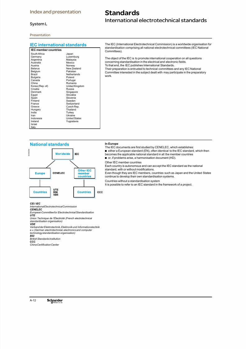
IEC international standardsIEC member countries
South AfricaGermany
Argentina Australia AustriaBelarusBelgiumBrazilBulgariaCanadaChinaKorea (Rep. of)CroatiaDenmarkEgyptSpainFinlandFranceGreece
HungaryIndiaIranIndonesiaIrelandIsraelItaly
JapanLuxemburgMalaysiaMexicoNorwayNew ZealandPakistanNetherlandsPolandPortugalRumaniaUnited KingdomRussiaSingaporeSlovakiaSloveniaSwedenSwitzerlandCzech Rep.
ThailandTurkeyUkraineUnited StatesYugoslavia
The IEC (International Electrotechnical Commission) is a worldwide organisation for
standardisation comprising all national electrotechnical committees (IEC National
Committees).
The object of the IEC is to promote international cooperation on all questions
concerning standardisation in the electrical and electronic elds.To that end, the IEC publishes International Standards.
Their preparation is entrusted to technical committees and any IEC National
Committee interested in the subject dealt with may participate in the preparatory
work.
National standards In Europe
The IEC documents are rst studied by CENELEC, which establishes:
either a European standard (EN), often identical to the IEC standard, which thenb
becomes the applicable national standard in all the member countries
or, if problems arise, a harmonisation document (HD).b
Other IEC member countriesEach country is autonomous and can accept the IEC standard as the national
standard, with or without modications.Even though they are IEC members, countries such as Japan and the United States
continue to develop their own standardisation systems.
Countries without a standardisation system
It is possible to refer to an IEC standard in the framework of a project.
CEI / IEC
International Electrotechnical CommissionCENELEC
European Committee for Electrotechnical StandardisationUTE
Union Technique de l’Électricité (French electrotechnicalstandardisation organisation)VDE
Verband der Elektrotechnik, Elektronik und Informationstechnike.v. (German electrotechnical, electronics and computertechnology standardisation organisation)BSI
British Standards InstitutionCCCChina Certifcation Center
D D 3 8 2 0 0 9
Presentation
StandardsInternational electrotechnical standards
Index and presentation
System L

8/15/2019 Prisma iPM System L Catalogue 2011
http://slidepdf.com/reader/full/prisma-ipm-system-l-catalogue-2011 17/128 A-13
The different types of standards There are different types of standards, including:
management standards,b
installation standards,b
product standards.b
Management standardsISO 9004: Quality management system - guidelines for performance improvement.
Used in setting up quality management systems.
ISO 9001: Quality management system - requirements. Used for certication audits.
ISO 14004: Environmental management system - major guidelines on the principles.
Systems and techniques implemented.
ISO 14001: Environmental management system - specication with guidance for
use.
A majority of Schneider Electric development centres and factories are certiedISO 9001 and ISO 14001.
Installation standardsThe set of IEC 60364-X standards denes the main principles and rules on:
assessment of general characteristics of installations,b
protection,b
selection and erection of equipment,b
verication and maintenance of installations.b
Product standardsThey apply to LV switchgear devices or LV switchgear assemblies, where the
purpose is to ensure the correct operation and safety of the concerned products.
standards on switchgear devices:b
v IEC 60947-1: general rules,
v IEC 60947-2: circuit breakers,
v IEC 60947-3: switches and disconnectors,v IEC 60947-4: contactors,
v IEC 62208 / EN 50298: empty enclosures.
standards on switchgear assemblies:b
v IEC 61439-1: General rules
v IEC 61439-2: Power switchgear and controlgear ASSEMBLIES (PSC-
ASSEMBLIES)
v IEC 61439-3: Distribution boards (to supersede IEC 60439-3)
v IEC 61439-4: ASSEMBLIES for construction sites (to supersede IEC 60439-4)
v IEC 61439-5: ASSEMBLIES for power distribution (to supersede IEC 60439-5)
v IEC 61439-6: Busbar trunking systems (to supersede IEC 60439-2).
Design and manufacture. Switchgear assemblies.
Switchgear devices. Installation.
RegulationsThe regulations in a given country may make certain standards legally binding and
may also create additional safety requirements.
Quality assurance In addition to providing proof of the conformity of its quality management system, a
product manufacturer can demonstrate the quality of products by providing proof
that their design and manufacture comply with the requirements in the applicable
standard.
Proof of conformity may be a declaration by the manufacturer or a certicate suppliedby an independent organisation.
D D 3 8 1 7 7 5
D D 3 8 1 7 7 6
D D 3 8 1 7 7 7
D D 3 8 1 7 7 8
Presentation
StandardsTools for quality assurance
Index and presentation
System L

8/15/2019 Prisma iPM System L Catalogue 2011
http://slidepdf.com/reader/full/prisma-ipm-system-l-catalogue-2011 18/128 A-14
All elements making up the electrical switchboard are concerned.
The object of standard IEC 61439-1 is to lay down the denitions and to state theservice conditions, construction requirements, technical characteristics and tests for
low-voltage switchgear and controlgear assemblies (U < 1000 V).The standard denes a low-voltage switchgear and controlgear assembly (theelectrical switchboard) as “a combination of one or more low-voltage switching
devices together with associated control, measuring, signalling, protective,
regulating equipment, etc., completely assembled under the responsibility of the
manufacturer with all the internal electrical and mechanical inter-connections and
structural parts”.
Standard IEC 61439-1 These tests ensure the conformity of the electrical switchboard and are intended to
check switchboard characteristics.
b tests are carried out on typical congurations
b routine tests are carried out on the completely nished switchboard. Their purposeis the check that the characteristics validated by the type tests were not altered
during the manufacturing operations.
The 12 design points tested byschneider electric
1 - Strength of materials and partsThe mechanical, electrical and thermal capability of constructional materials and
parts of the assembly shall be deemed to be proven by verication of constructionand performance characteristics.
where an empty enclosure in accordance with IEC 62208 is used, and it has not
been modied so as to degrade the performance of the enclosure, no repetition of
the enclosure testing is required.
2 - Degree of protection of assembliesThe degree of protection shall be veried in accordance with IEC 60529; the testmay be carried out on a representative equipped assembly. Where an empty
enclosure in accordance with IEC 62208 is used, and no external modication hasbeen carried out that may result in a deterioration of the degree of protection, no
further testing is required.
3 - Clearances and creepage distancesFor dimensioning clearances and creepage distances between separate circuits, the
highest voltage ratings shall be used (rated impulse withstand voltage for clearances
and rated insulation voltage for creepage distances).
The clearances and creepage distances apply to phase to phase, phase to neutral,
and except where a conductor is connected directly to earth, phase to earth and
neutral to earth.
4 - Protection against electric shock and integrity of protective
circuitsb Effectiveness of the protective circuit
b Effective earth continuity between the exposed conductive parts of the assembly
and the protective circuit
b Short-circuit withstand strength of the protective circuit
5 - Incorporation of switching devices and componentsCompliance with the design requirements, the incorporation of switching devices
and components shall be conmed by inspection and veried to the requirements of
this standard.
b Electromagnetic compatibility
6 - Internal electrical circuits and connections
7 - Terminals for external conductorsCompliance with the design requirements for terminals for external conductors shall
be conrmed by inspection.
8 - Dielectric properties All the electrical equipment of the assembly shall be connected, except those items
of apparatus which, according to the relevant specications, are designed for a lower
test voltage; current-consuming apparatus (e.g. windings, measuring instruments,
voltage surge suppression devices) in which the application of the test voltage wouldcause the ow of a current, shall be disconnected. Such apparatus shall be
disconnected at one of their terminals unless they are not designed to withstand the
full test voltage, in which case all terminals may be disconnected.
Presentation
StandardsStandards IEC 61439-1
Index and presentation
System L

8/15/2019 Prisma iPM System L Catalogue 2011
http://slidepdf.com/reader/full/prisma-ipm-system-l-catalogue-2011 19/128 A-15
Routine tests Series of test under responsibility of the assemblers that must be performed for each
LV assembly.
1 - General inspection of the assembly
2 - Dielectric test3 - Checking of protective measures and of the electrical
continuity of the protective circuits.
9 - Verication of temperature riseb Verication by testing with current
b Derivation of ratings for similar variants
b Verication by calculation
10 - Short-circuit withstand strengthThe short-circuit withstand strength declared by the originalmanufacturer shall be
veried. Verication may be by the application of design rules, by calculation or bytest as specied.
b Circuits of assemblies which are exempted from the verication of the short-circuit
withstand strength
b Verication by the application of design rules
b Verication by comparison with a reference design
b Verication by test
11 - Electromagnetic compatibility(EMC)b Assembles not incorporating electronic circuits
b Assembles incorporating electronic circuits
12 - Mechanical operationThis verication test shall not be made on such devices of the assembly which have
already been type tested according to their relevant product standard unless their
mechanical operation is impaired by their mounting.
For parts, which need verication by test, satisfactory mechanical operation shall be
veried after installation in the assembly. The number of operating cycles shall be
200.
Presentation
StandardsStandards IEC 61439-1
Index and presentation
System L

8/15/2019 Prisma iPM System L Catalogue 2011
http://slidepdf.com/reader/full/prisma-ipm-system-l-catalogue-2011 20/128 A-16
Standards IEC 62208 and EN 50298
Empty enclosures for low-voltage switchgear and
controlgear assemblies
General rules for empty enclosures
Standards IEC 62208 and EN 50298 lay down denitions, classications,characteristics and test requirements for the enclosures used for assemblies.
They apply to empty enclosures before installation of the devices by the panelbuilder, as supplied by the manufacturer.
They apply to one-piece enclosures and to enclosures supplied in kit form.
Type tests 1 - Static load
2 - Hoisting
3 - Axial loads of metal inserts
4 - IK code
5 - IP code
6 - Thermal stability
7 - Resistance to heat
8 - Resistance to abnormal heat and to re
9 - Dielectric strength
10 - Protective-circuit continuity
11 - Weather resistance12 - Corrosion resistance
13 - Marking.
Presentation
StandardsEnclosure standards
IEC 62208 and EN 50298
Index and presentation
System L
8/15/2019 Prisma iPM System L Catalogue 2011
http://slidepdf.com/reader/full/prisma-ipm-system-l-catalogue-2011 21/128 A-17
A switchboard must comply with the requirements in standard IEC 61439-1 to
guarantee the safety and reliability of the installation.
Managers of installations, fully aware of the professional and legal liabilities weighing on their
company and on themselves, demand a high level of safety for the electrical installation.What is more, the serious economic consequences of prolonged halts in production
mean that the electrical switchboard must provide excellent continuity of service,
whatever the operating conditions.
The Schneider Electric solution Specify switchboards that comply with standard IEC 61439-1.b
Guarantee a level of safety that has been 100% tested, from the day theb
switchboard is installed and throughout its service life.
Ensure the return on investment through easy upgrading of the installation inb
compliance with the standard.
Guarantee that the switchboard complies with the technical specications.b
Prisma iPM tested switchboards
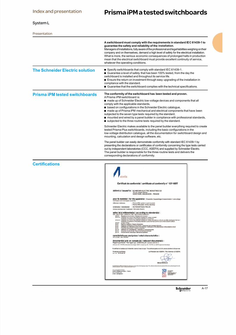
Certications
The conformity of the switchboard has been tested and proven.
A Prisma iPM switchboard is:
made up of Schneider Electric low-voltage devices and components that allb
comply with the applicable standards,based on congurations in the Schneider Electric catalogue,b
made up of Prisma iPM mechanical and electrical components that have beenb
subjected to the seven type tests required by the standard,
mounted and wired by a panel builder in compliance with professional standards,b
subjected to the three routine tests required by the standard.b
Schneider Electric makes available to the panel builder everything required to create
tested Prisma Plus switchboards, including the basic congurations in thelow-voltage distribution catalogue, all the documentation for switchboard design and
mounting, calculation and design software, etc.
The panel builder can easily demonstrate conformity with standard IEC 61439-1 by
presenting the declarations or certicates of conformity concerning the type tests carried
out by independent laboratories (CCC, ASEFA) and supplied by Schneider Electric.
The panel builder is responsible for the three routine tests and delivers the
corresponding declarations of conformity.
Presentation
Prisma iPM a tested switchboardsIndex and presentation
System L

8/15/2019 Prisma iPM System L Catalogue 2011
http://slidepdf.com/reader/full/prisma-ipm-system-l-catalogue-2011 22/128 A-18
Wall mounted system L
up to 630 A
Currents up to 6300 A.
Currents up to 630 A.
Currents up to 250 A.
Incoming feeders and main LV
switchboards
Power distribution
and loads
Currents up to 4000 A.
Currents up to 4000 A.
D D 8 0 0 4 6 2
Presentation
Index and presentation
System L

8/15/2019 Prisma iPM System L Catalogue 2011
http://slidepdf.com/reader/full/prisma-ipm-system-l-catalogue-2011 23/128 A-19
Wall mounted system L
up to 630 A
Main characteristicsIn-door wall mounted system
Electrical characteristics
Nominal rated current (A) 630
Rated insulation voltage Ui
(V AC)
1000
Rated operation voltage
(V AC)
690
Rated impulse withstand
voltage (KV)
8
Frequency (Hz) 50 / 60
Main busbar rated current
max. Ie (A)
630
Rated short-time withstand
current Icw (KA / 1 s.)
25
Rated peak withstand
current Ipk (KA)
53
Neutral network TNC v TNS v IT v TT v
Enclosure characteristics (dimensions, IP, …)
Overall height (mm) 300 500 700 900 1100 1300 1650 1850
Number of vertical modules
(functional height)
1 module = 50 mm
4 8 12 16 20 24 28 32
Depth (mm) 235 305
Width of enclosure for
devices (mm)
600
Width of cable duct (mm) 300
Partitioning 1
IP 30 / 31 / 40 / 54
IK 07 / 08 / 10
Aplicable standards
Type test IEC61439-1
IP class IEC60529Insulation materials inside
of enclosures
IEC60695
Environment conditions
Operation indoor
Altitude max. (m) 2000
Temperature average max.
(˚C)
35
Temperature max. (˚C) 45
Temperature min. (˚C) 0
Moisture 40 % to 20 %
Climatic class T2
Degree of pollution 3
OthersEnclosure materials sheet metal
Painting epoxy resin powder electrostatic sprayed
Colour RAL 7047 (enclosure) and RAL 9022 (functional unit)
Insulation materials inside
of enclosure
high-temperature withstand, combustion self-prevent
D D 8 0 0 1 6 2
Presentation
Index and presentation
System L
8/15/2019 Prisma iPM System L Catalogue 2011
http://slidepdf.com/reader/full/prisma-ipm-system-l-catalogue-2011 24/128 A-20
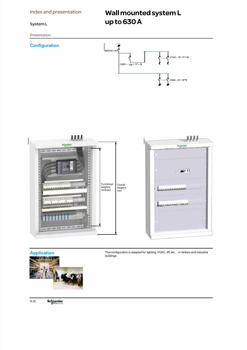
Wall mounted system L
up to 630 A
Vigi
Application This conguration is adapted for lighting, HVAC, lift, etc… in tertiary and industrial
buildings.
Conguration D D 8 0 0 3 3 2
Presentation
P D 8 0 0 0 6 9
Functionalheight inmodules
Overallheight inmm
P D 8 0 0 0 7 1
Index and presentation
System L
8/15/2019 Prisma iPM System L Catalogue 2011
http://slidepdf.com/reader/full/prisma-ipm-system-l-catalogue-2011 25/128 A-21
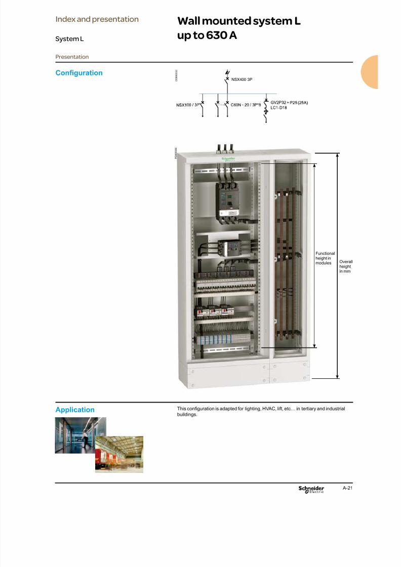
Wall mounted system L
up to 630 A
NSX400 3P
Conguration
Application This conguration is adapted for lighting, HVAC, lift, etc… in tertiary and industrial
buildings.
D D 8 0 0 3 3 3
Presentation
Functionalheight inmodules Overall
heightin mm
P D 8 0 0 0 6 6
Index and presentation
System L

8/15/2019 Prisma iPM System L Catalogue 2011
http://slidepdf.com/reader/full/prisma-ipm-system-l-catalogue-2011 26/128 A-22
Tools and services
Presentation
Index and presentation
System L
PromotionalPromotional leaetsb
Posters, videosb
Customer conferencesb
Advice, order
Catalogueb
Specications
Type tested conferenceb
New IEC conferenceb
Specication formsb
Software
Flash quotationb
Specications
& tendering
Order
Design &
implementation
Advice, order
Catalogueb
Software
Bom toolb
On-line support
Customer Care Center b
Training
Training sessionsb
Design, order Catalogueb
Technicial guide for Pnbb
Software
Thermal calculationb
Technical information
AutoCAD libraryb
Bars drawings libraryb
Derating tablesb
On-line support
Customer Care Center b
Schneider Electric provides a large range of tools and
services to support you all along the life cycle of the
product.
For futher information, please consult us or see
Schneider Electric website:
www.schneider-electric.com.

8/15/2019 Prisma iPM System L Catalogue 2011
http://slidepdf.com/reader/full/prisma-ipm-system-l-catalogue-2011 27/128 A-23
Tools and services
Presentation
Index and presentation
System L
Commissioning
Operation
& recycling
Assembling
Guides
Technical guide for Pnbb
Mounting leaets libraryb
Busbar drawingsb
Guides
Technical guide forb
Pnb
Operation
Technical guide for Pnbb
RecyclingProduct Environmentalb
Prole
D D 8 0 0 1 6 3
P B 8 0 0 0 5 9

8/15/2019 Prisma iPM System L Catalogue 2011
http://slidepdf.com/reader/full/prisma-ipm-system-l-catalogue-2011 28/128

8/15/2019 Prisma iPM System L Catalogue 2011
http://slidepdf.com/reader/full/prisma-ipm-system-l-catalogue-2011 29/128 A-25
Determining the commercial
number
Commercial reference
Using the circuit diagram
Draw up the list of devices to be installed grouping
them together in families.
And using the commercial
number tables
Reminder: 1 module = 50 mm
The selection of the functional unit is done after
selectioning the electrical devices (circuit breakers,
modular switchgears, etc.).
1 For the incoming unit, if it is not installed in the duct,
determine:
the number of vertical modules required;b
the commercial numbers for mounting plate andb
front plates.
Determine the connection and its width so as to
connect the incoming unit to the busbars, or the
distribution block and its width.
Circuitbreaker
Mountingplate
Front plates No. ofverticalmodule
cut-out upstream downstream
INS 250 LSL58816V LSX58905V LSX58931A LSX58932A 8
Set of4 drilled bars
Busbarsupport
Frontbarrier
Mountinghardware
04172 4 x LSX58082A 04197 04195
2 For the outgoing units, determine:
the number of vertical modules required,b
the commercial numbers for the modular rail and theb
front plate,
Modulardevices
Modularrail
Front plate Additionalfront plate
No. of verticalmodule
1 rowMulti 9(1)
LSL58801A LSX58884A LSX58931A 5
(1) 48 x 9 mm.
Distribution block Quantity Com. no.
Multicl ip 200 A, 3P 1 LSX58053A
the distribution block: Multiclip, comb, etc.b
Module total = 18
Height of the corresponding enclosure = 203 Add-up the number of modules required.
4 Based on the degree of protection IP, on the number
of modules required, choose the enclosure.
Enclosure Com. no.
IP30 / wall mounted enclosure W = 600 mm,D = 235 mm, H = 1100 mm, 20 modules
LSL58220A
IP30 / wall mounted enclosure with door W = 300 mm,D = 235 mm, H = 1100 mm, 20 modules
LSL58234A
Transparent door W = 600 mm, H = 1100 mm,20 modules
LSL58165T
5 If the devices to be installed do not occupy the whole
enclosure, complete the front panel with an extra plain
front plate.
Plain front plate Com. no.
20 - 18 = 2 modules LSX58932A
6 Determine the necessary accessories:for distribution,b
for cable running,b
for the overall installation.b
Description Com. no.12 cable straps for horizontal cables 04239
4 covers for horizontal cable straps L = 430 mm 04243
4 wall mounted cable tie supports, W = 300 mm LSL58293A
4 wall mounted cable tie supports, W = 600 mm LSL58296A
Cu earth / neutral bar, 24 modules LSX58070A
Circuit breaker Mounting plate Front plate No. of verticalmodule
NSX 100 LSL58815H LSX58900H 5
LSX58931A
D D 8 0 0 1 3 7
D D 8 0 0 0 0 6
D D 8 0 0 1 4 0
D D 8 0 0 0 1 9
D D 3 8 1 5 8 3
D D 8 0 0 1 3 8
D D 8 0 0 1 3 9
Index and presentation
System L

8/15/2019 Prisma iPM System L Catalogue 2011
http://slidepdf.com/reader/full/prisma-ipm-system-l-catalogue-2011 30/128
8/15/2019 Prisma iPM System L Catalogue 2011
http://slidepdf.com/reader/full/prisma-ipm-system-l-catalogue-2011 31/128B-1
Contents
Description B-2Functional units up to 630 A B-2
Commercial numbers B-4Compact NSX 400 to 630 A B-4
Compact NSX 100 to 250 A B-6
Compact CVS 400 to 630 A B-8
Compact CVS 100 to 250 A B-10
Easypact EZC from 100 to 400 A B-12
Interpact INS 250 to 630 A B-14
Fupact INF 32 to 160 A B-16
Widths of modular devices B-18
Multi 9 ≤ 63 A B-20
NG 125, C120 B-20
INS 40 / 160 switch disconnectors B-22
Industrial and control devices B-24
Human / Machine interface B-26Other devices B-28
Reserve space B-29
Functional unit accessories B-30
Functional units
System L

8/15/2019 Prisma iPM System L Catalogue 2011
http://slidepdf.com/reader/full/prisma-ipm-system-l-catalogue-2011 32/128B-2
Functional units up to 630 A
Description
D D 8 0 0 4 3 2
P D 8 0 0 0 0 3
The functional unit is dened in the IEC 61439.1 standard as
followed:
“A part of an assembly comprising all the mechanical and electricalelements that contribute to the fullment of the same function.”
Each device is part of a functional unit comprising:
a dedicated mounting plate for device installation,ba front plate to block direct access to live parts,bthe device connections or distribution solutions,bsystems for on-site connections and running of auxiliary wires.b
The functional units are modular and are arranged rationally, one on top of another,
within the enclosure.
The system includes everything required for functional unit mounting, supply and on
site connection.
The components of the Prisma iPM functional units have been designed and tested
taking into account device characteristics.
This design approach ensures a high degree of reliability in system operation and
optimum safety for people.
The devices are mounted on a mounting plate. The space occupied by the mounting
plate corresponds to the device dimensions: optimization of the occupied space.
Prisma iPM offers a complete range of mounting plates for each type of devices up
to 630 A:
Compact CVS and NSX,bInterpact INS,bEasypact EZC,bmodular devices,...b
Plain or slotted mounting plates are available for other devices.
The mounting plates have threaded holes for direct mounting from the front.
The xing screws of the mounting plate are supplied with.
The mounting plates have slots for tightening power cable and auxiliary connection.
It is front connected, without nuts, using thread-forming screws.
The use of thread-forming screws is mandatory to ensure electrical continuity
between exposed conductive parts.
Mounting plates
Functional units
System L
8/15/2019 Prisma iPM System L Catalogue 2011
http://slidepdf.com/reader/full/prisma-ipm-system-l-catalogue-2011 33/128B-3
Functional units up to 630 A
Description
D D 8
0 0 1 2 3
D D 8 0 0 2 7 9
D D 8 0 0 4 6 5
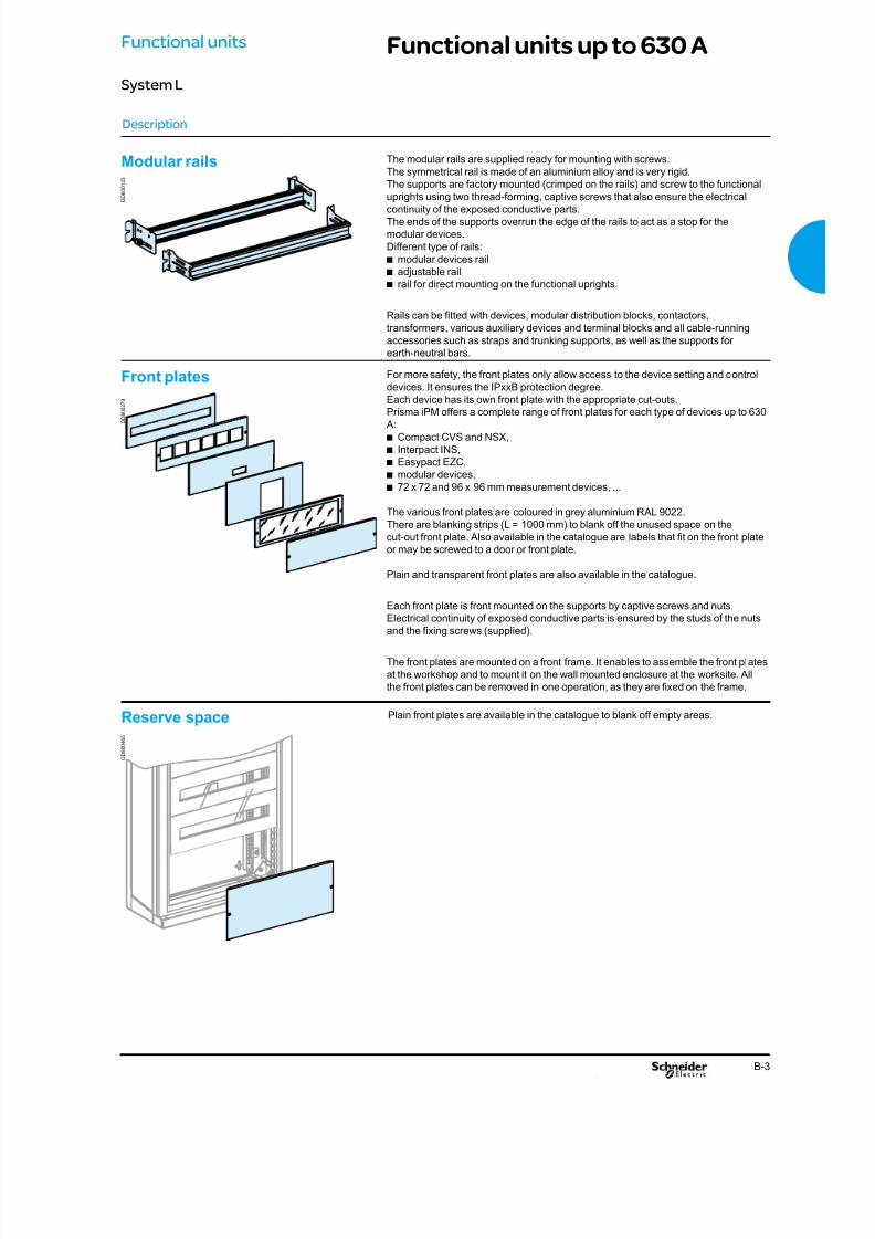
The modular rails are supplied ready for mounting with screws.
The symmetrical rail is made of an aluminium alloy and is very rigid.
The supports are factory mounted (crimped on the rails) and screw to the functional
uprights using two thread-forming, captive screws that also ensure the electricalcontinuity of the exposed conductive parts.
The ends of the supports overrun the edge of the rails to act as a stop for the
modular devices.
Different type of rails:
modular devices railbadjustable railbrail for direct mounting on the functional uprights.b
Rails can be tted with devices, modular distribution blocks, contactors,
transformers, various auxiliary devices and terminal blocks and all cable-running
accessories such as straps and trunking supports, as well as the supports for
earth-neutral bars.
For more safety, the front plates only allow access to the device setting and control
devices. It ensures the IPxxB protection degree.Each device has its own front plate with the appropriate cut-outs.
Prisma iPM offers a complete range of front plates for each type of devices up to 630
A:
Compact CVS and NSX,bInterpact INS,bEasypact EZC,bmodular devices,b72 x 72 and 96 x 96 mm measurement devices, ...b
The various front plates are coloured in grey aluminium RAL 9022.
There are blanking strips (L = 1000 mm) to blank off the unused space on the
cut-out front plate. Also available in the catalogue are labels that t on the front plate
or may be screwed to a door or front plate.
Plain and transparent front plates are also available in the catalogue.
Each front plate is front mounted on the supports by captive screws and nuts.
Electrical continuity of exposed conductive parts is ensured by the studs of the nuts
and the xing screws (supplied).
The front plates are mounted on a front frame. It enables to assemble the front plates
at the workshop and to mount it on the wall mounted enclosure at the worksite. All
the front plates can be removed in one operation, as they are xed on the frame.
Plain front plates are available in the catalogue to blank off empty areas.Reserve space
Front plates
Modular rails
Functional units
System L
8/15/2019 Prisma iPM System L Catalogue 2011
http://slidepdf.com/reader/full/prisma-ipm-system-l-catalogue-2011 34/128B-4
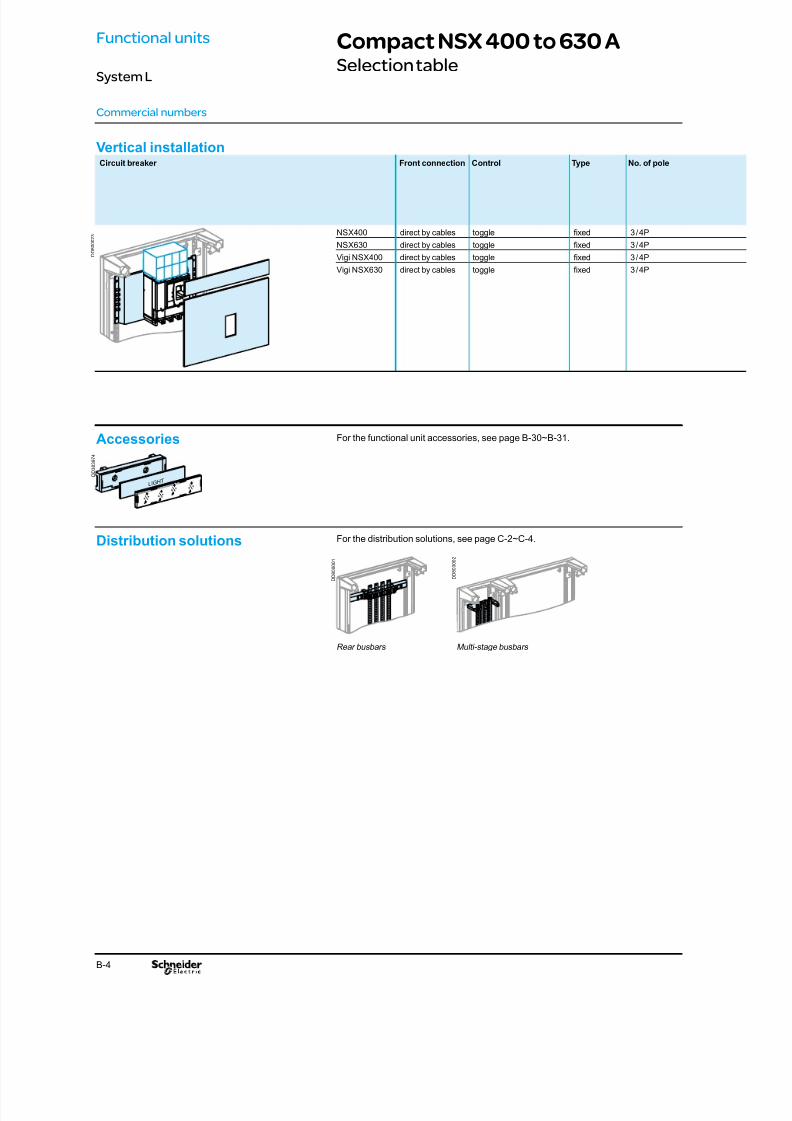
Vertical installationCircuit breaker Front connection Control Type No. of pole
NSX400 direct by cables toggle xed 3 / 4P
NSX630 direct by cables toggle xed 3 / 4P
Vigi NSX400 direct by cables toggle xed 3 / 4P
Vigi NSX630 direct by cables toggle xed 3 / 4P
Compact NSX 400 to 630 ASelection table
Commercial numbers
LIGHT
Accessories
Distribution solutions
Rear busbars Multi-stage busbars
For the functional unit accessories, see page B-30~B-31.
For the distribution solutions, see page C-2~C-4.
D D 8 0 0 0 0 1
D D 8 0 0 0 0 2
D D 8 0 0 0 2 3
D D 3 8 3 9 7 4
Functional units
System L

8/15/2019 Prisma iPM System L Catalogue 2011
http://slidepdf.com/reader/full/prisma-ipm-system-l-catalogue-2011 35/128B-5
No. of vertical modules
(1 module = 50 mm)
Mounting plate Front plate Long terminal
shieldcut-out + upstream + downstream
11 LSL58820V 9 modules LSX58913V 1 modules LSX58931A 1 modules LSX58931A b
14 LSL58820V 9 modules LSX58913V 2 modules LSX58932A 3 modules LSX58933A b
13 LSL58820V 9 modules LSX58921V 2 modules LSX58932A 2 modules LSX58932A b
16 LSL58820V 9 modules LSX58921V 3 modules LSX58933A 4 modules LSX58934A b
Mandatory.
Optional.
Compact NSX 400 to 630 ASelection table
Commercial numbers
Functional units
System L
D D 8 0 0 1 7
8
D D 8 0 0 1 7 9
D D 8 0 0 1 8 0
D D 8 0 0 1 8 1
8/15/2019 Prisma iPM System L Catalogue 2011
http://slidepdf.com/reader/full/prisma-ipm-system-l-catalogue-2011 36/128B-6
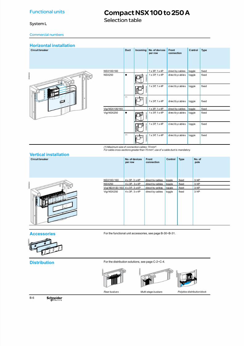
Horizontal installationCircuit breaker Duct Incoming No. of devices
per row
Front
connection
Control Type
NSX100/160 1 x 3P, 1 x 4P direct by cables toggle xed
NSX250 b 1 x 3P, 1 x 4P direct by cables toggle xed
1 x 3P, 1 x 4P direct by cables toggle xed
(1)
1 x 3P, 1 x 4P direct by cables toggle xed
Vigi NSX100/160 1 x 3P, 1 x 4P direct by cables toggle xed
Vigi NSX250 b 1 x 3P, 1 x 4P direct by cables toggle xed
1 x 3P, 1 x 4P direct by cables toggle xed
(1) 1 x 3P, 1 x 4P direct by cables toggle xed
(1) Maximum size of connection cables: 70 mm².For cable cross-sections greater than 70 mm², use of a cable duct is mandatory.
Vertical installationCircuit breaker No. of devices
per row
Front
connection
Control Type No. of
pole
NSX100 / 160 4 x 3P, 3 x 4P direct by cables toggle xed 3 / 4P
NSX250 4 x 3P, 3 x 4P direct by cables toggle xed 3 / 4P
Vigi NSX100 / 160 4 x 3P, 3 x 4P direct by cables toggle xed 3 / 4P
Vigi NSX250 4 x 3P, 3 x 4P direct by cables toggle xed 3 / 4P
Compact NSX 100 to 250 ASelection table
Commercial numbers
D D 8 0 0 0 2 5
D D 8 0 0 0 2 4
D D 8 0 0 1 8 3
D D 8 0 0 1 8 4
D D 8 0 0 5 2 9
D D 8 0 0 5 2 9
D D 8 0 0 1 8 3
D D 8 0 0 1 8 4
Distribution
Rear busbars Multi-stage busbars
For the distribution solutions, see page C-2~C-4.
Polybloc distribution block
D D 8 0 0 0 0
1
D D 8 0 0 0 0 2
D D 8 0 0 4 6 3
Functional units
System L
LIGHT
Accessories For the functional unit accessories, see page B-30~B-31.
D D 3 8 3 9 7 4

8/15/2019 Prisma iPM System L Catalogue 2011
http://slidepdf.com/reader/full/prisma-ipm-system-l-catalogue-2011 37/128B-7
No. of pole No. of vertical
modules(1 module = 50 mm)
Mounting plate Front plate
cut-out + upstream + downstream
3 / 4P 5 LSL58815H 4 modules LSX58904H 1 module LSX58931A - -
3 / 4P 6 LSL58815H 4 modules LSX58904H - 2 modules LSX58932A
3 / 4P 6 LSL58815H 4 modules LSX58904H 2 modules LSX58932A -
3 / 4P 8 LSL58815H 4 modules
LSX58904H 2 modules LSX58932A 2 modules LSX58932A
3 / 4P 5 LSL58815H 4 modules LSX58904H 1 module LSX58931A - -
3 / 4P 6 LSL58815H 4 modules LSX58904H - 2 modules LSX58932A
3 / 4P 6 LSL58815H 4 modules LSX58904H 2 modules LSX58932A -
3 / 4P 8 LSL58815H 4 modules LSX58904H 2 modules LSX58932A 2 modules LSX58932A
No. of vertical modules
(1 module = 50 mm)
Mounting plate Front plate Blanking strip
cut-out + upstream + downstream
6 LSL58816V 5 modules LSX58902V - 1 modules LSX58931A LSX58751A
9 LSL58816V 5 modules LSX58902V 2 modules LSX58932A 2 modules LSX58932A LSX58751A
8 LSL58816V 7 modules LSX58903V - 1 modules LSX58931A LSX58751A
11 LSL58816V 7 modules LSX58903V 2 modules LSX58932A 2 modules LSX58932A LSX58751A
Mandatory.
Optional.
Compact NSX 100 to 250 ASelection table
Commercial numbers
D D 8 0 0 1 7 8
D D 8 0 0 1 7 9
D D 8 0 0 1 8 0
D D 8 0 0 1 8 1
D D 8 0 0 1 8 2
D D 8 0 0 1 7 9
D D 8 0 0 1 8 0
D D 8 0 0 1 8 1
Functional units
System L
8/15/2019 Prisma iPM System L Catalogue 2011
http://slidepdf.com/reader/full/prisma-ipm-system-l-catalogue-2011 38/128B-8
Compact CVS 400 to 630 ASelection table
Commercial numbers
LIGHT
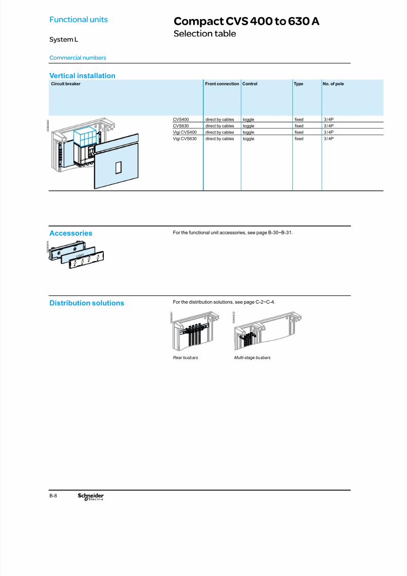
Accessories For the functional unit accessories, see page B-30~B-31.
D D 3 8 3 9 7 4
Distribution solutions For the distribution solutions, see page C-2~C-4.
Rear busbars Multi-stage busbars
D D 8 0 0 0 0 1
D D 8 0 0 0 0 2
Functional units
System L
Vertical installationCircuit breaker Front connection Control Type No. of pole
CVS400 direct by cables toggle xed 3 / 4P
CVS630 direct by cables toggle xed 3 / 4P
Vigi CVS400 direct by cables toggle xed 3 / 4P
Vigi CVS630 direct by cables toggle xed 3 / 4P
D D 8 0 0 0 0 0

8/15/2019 Prisma iPM System L Catalogue 2011
http://slidepdf.com/reader/full/prisma-ipm-system-l-catalogue-2011 39/128B-9
Compact CVS 400 to 630 ASelection table
Commercial numbers
Functional units
System L
No. of vertical modules
(1 module = 50 mm)
Mounting plate Front plate Long terminal
shieldcut-out + upstream + downstream
11 LSL58820V 7 modules LSX58911V 2 modules LSX58932A 2 modules LSX58932A b
14 LSL58820V 7 modules LSX58911V 3 modules LSX58933A 4 modules LSX58934A b
13 LSL58820V 9 modules LSX58912V 2 modules LSX58932A 2 modules LSX58932A b
16 LSL58820V 9 modules LSX58912V 3 modules LSX58933A 4 modules LSX58934A b
Mandatory.
Optional.
D D 8 0 0 1 7 8
D D 8 0 0 1 7 9
D D 8 0 0 1 8 0
D D 8 0 0 1 8 1
8/15/2019 Prisma iPM System L Catalogue 2011
http://slidepdf.com/reader/full/prisma-ipm-system-l-catalogue-2011 40/128B-10
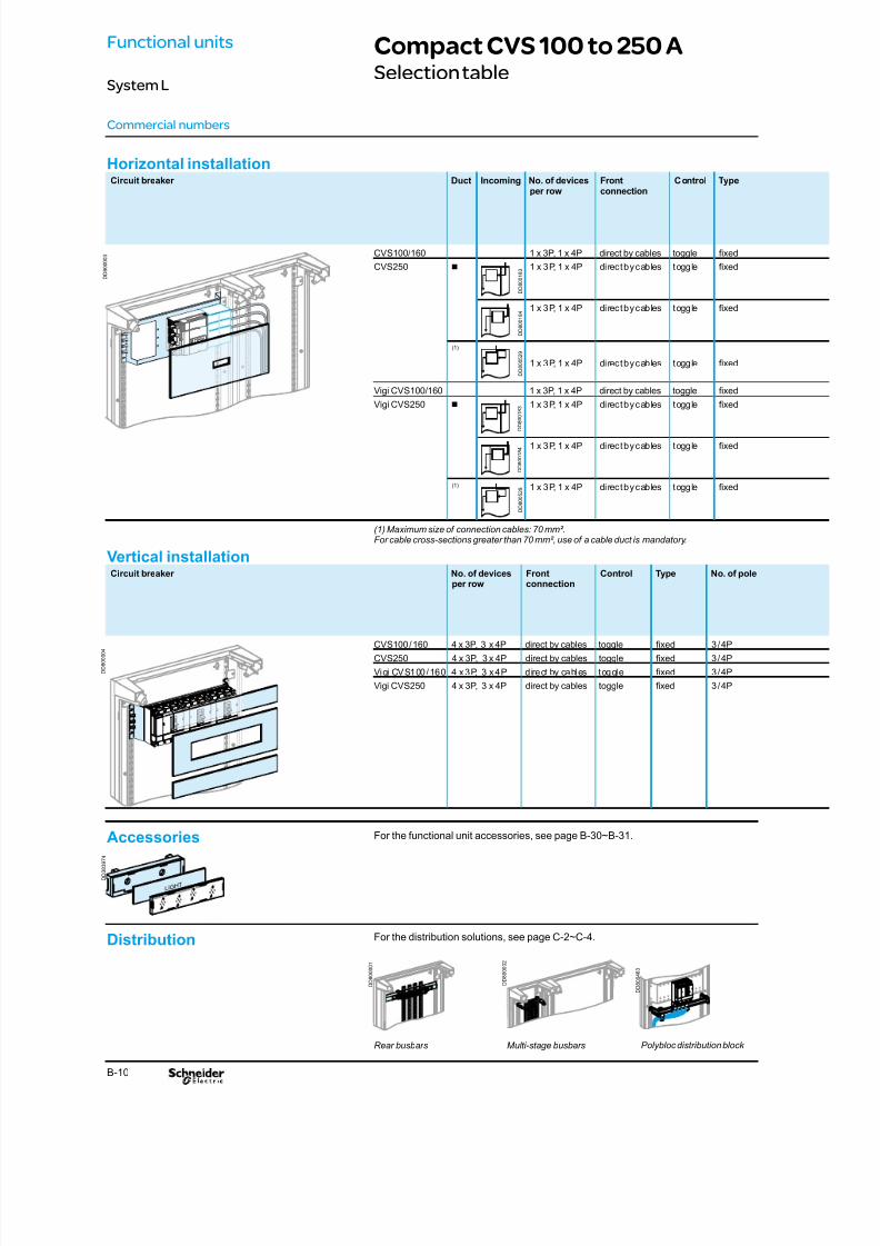
Horizontal installationCircuit breaker Duct Incoming No. of devices
per row
Front
connection
Control Type
CVS100/160 1 x 3P, 1 x 4P direct by cables toggle xed
CVS250 b 1 x 3P, 1 x 4P direct by cables toggle xed
1 x 3P, 1 x 4P direct by cables toggle xed
(1)
1 x 3P, 1 x 4P direct by cables toggle xed
Vigi CVS100/160 1 x 3P, 1 x 4P direct by cables toggle xed
Vigi CVS250 b 1 x 3P, 1 x 4P direct by cables toggle xed
1 x 3P, 1 x 4P direct by cables toggle xed
(1) 1 x 3P, 1 x 4P direct by cables toggle xed
(1) Maximum size of connection cables: 70 mm².For cable cross-sections greater than 70 mm², use of a cable duct is mandatory.
Vertical installationCircuit breaker No. of devices
per row
Front
connection
Control Type No. of pole
CVS100 / 160 4 x 3P, 3 x 4P direct by cables toggle xed 3 / 4P
CVS250 4 x 3P, 3 x 4P direct by cables toggle xed 3 / 4P
Vigi CVS100 / 160 4 x 3P, 3 x 4P direct by cables toggle xed 3 / 4P
Vigi CVS250 4 x 3P, 3 x 4P direct by cables toggle xed 3 / 4P
Compact CVS 100 to 250 ASelection table
Commercial numbers
D D 8 0 0 1 8 3
D D 8 0 0 1 8 4
D D 8 0 0 5 2 9
D D 8 0 0 5 2 9
D D 8 0 0 1 8 3
D D 8 0 0 1 8 4
LIGHT
Accessories For the functional unit accessories, see page B-30~B-31.
D D 3 8 3 9 7 4
Distribution
Rear busbars Multi-stage busbars
For the distribution solutions, see page C-2~C-4.
Polybloc distribution block
D D 8 0 0
0 0 1
D D 8 0 0 0 0 2
D D 8 0 0 4 6
3
D D 8 0 0 0 0 3
D D 8 0 0 0 0 4
Functional units
System L

8/15/2019 Prisma iPM System L Catalogue 2011
http://slidepdf.com/reader/full/prisma-ipm-system-l-catalogue-2011 41/128B-11
No. of
pole
No. of vertical
modules(1 module = 50 mm)
Mounting plate Front plate
cut-out + upstream + downstream
3 / 4P 5 LSL58815H 4 modules LSX58900H 1 module LSX58931A - -
3 / 4P 6 LSL58815H 4 modules LSX58900H - 2 modules LSX58932A
3 / 4P 6 LSL58815H 4 modules LSX58900H 2 modules LSX58932A -
3 / 4P 8 LSL58815H 4 modules
LSX58900H 2 modules LSX58932A 2 modules LSX58932A
3 / 4P 5 LSL58815H 4 modules LSX58900H 1 module LSX58931A - -
3 / 4P 6 LSL58815H 4 modules LSX58900H - 2 modules LSX58932A
3 / 4P 6 LSL58815H 4 modules LSX58900H 2 modules LSX58932A -
3 / 4P 8 LSL58815H 4 modules LSX58900H 2 modules LSX58932A 2 modules LSX58932A
No. of vertical modules
(1 module = 50 mm)
Mounting plate Front plate Blanking strip
cut-out + upstream + downstream
7 LSL58816V 5 modules LSX58902V - 2 modules LSX58932A LSX58751A
9 LSL58816V 5 modules LSX58902V 2 modules LSX58932A 2 modules LSX58932A LSX58751A
9 LSL58816V 7 modules LSX58903V - 2 modules LSX58932A LSX58751A
11 LSL58816V 7 modules LSX58903V 2 modules LSX58932A 2 modules LSX58932A LSX58751A
Mandatory.
Optional.
Compact CVS 100 to 250 ASelection table
Commercial numbers
D D 8 0 0 1 7 8
D D 8 0 0 1 7 9
D D 8 0 0 1 8 0
D D 8 0 0 1 8 1
D D 8 0 0 1 8 2
D D 8 0 0 1 7 9
D D 8 0 0 1 8 0
D D 8 0 0 1 8 1
Functional units
System L

8/15/2019 Prisma iPM System L Catalogue 2011
http://slidepdf.com/reader/full/prisma-ipm-system-l-catalogue-2011 42/128B-12
Easypact EZC from 100 to 400 ASelection table
Commercial numbers
LIGHT
Accessories For the functional unit accessories, see page B-30~B-31.
D D 3 8 3 9 7 4
Distribution solutions
Rear busbars Multi-stage busbars
For the distribution solutions, see page C-2~C-4.
D D 8 0 0 0 0 2
D D 8 0 0 0 0 1
Functional units
System L
Horizontal installationCircuit breaker Duct Incoming No. of
devicesper row
Front
connection
Control Type
EZC100 1 x 3P direct by cables toggle xed
EZC250 b 1 x 3/4P direct by cables toggle xed
1 x 3/4P direct by cables toggle xed
(1) 1 x 3/4P direct by cables toggle xed
(1) Maximum size of connection cables: 70 mm².For cable cross-sections greater than 70 mm², use of a cable duct is mandatory.
(2) If EZC100 connected to rear busbars, add a 2 modules front plate LSX58932A.
Vertical installationCircuit breaker No. of devices
per rowFrontconnection
Control Type No. of pole
EZC100 5 x 3P, 3 x 4P direct by cables toggle xed 3 / 4P
EZC250 4 x 3P direct by cables toggle xed 3P
3 x 4P direct by cables toggle xed 4PEZC400 1 x 3P direct by cables toggle xed 3P
D D 8 0 0 0 0 7
D D 8 0 0 0 3 6
D D 8 0 0 1 8 3
D D 8 0 0 1 8 4
D D 8 0 0 5 2 9
8/15/2019 Prisma iPM System L Catalogue 2011
http://slidepdf.com/reader/full/prisma-ipm-system-l-catalogue-2011 43/128B-13
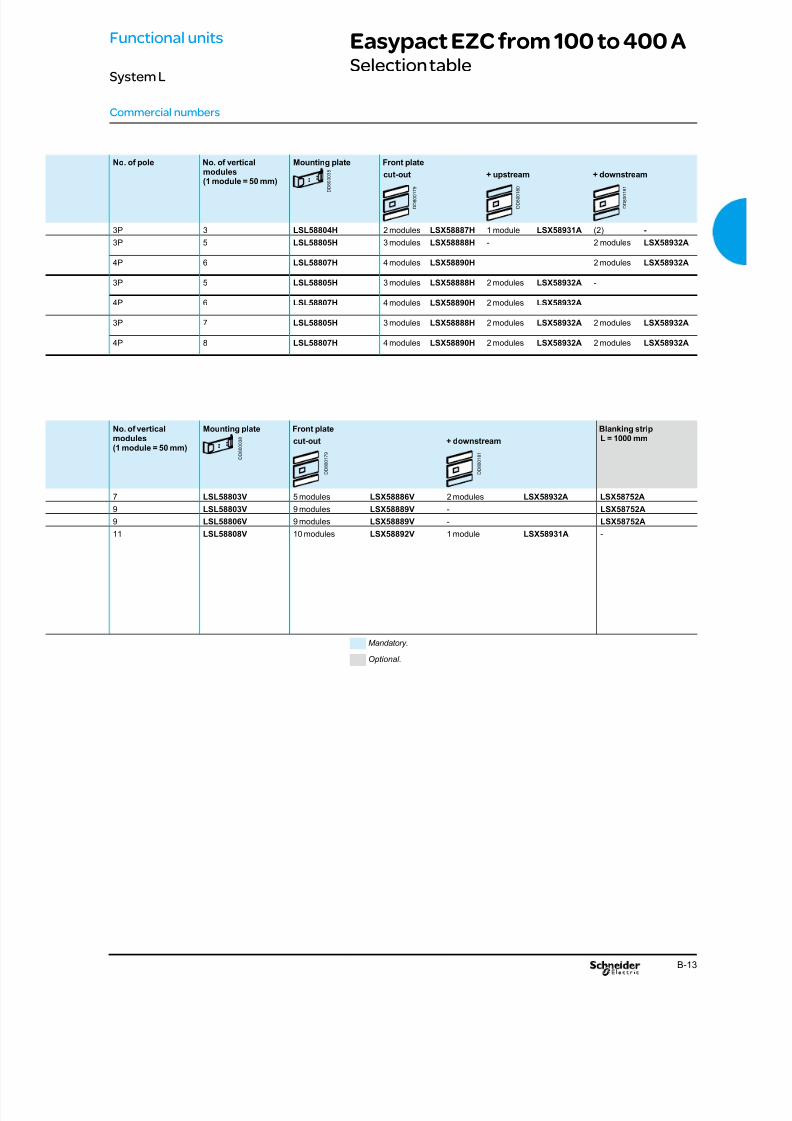
Easypact EZC from 100 to 400 ASelection table
Commercial numbers
Functional units
System L
No. of pole No. of vertical
modules(1 module = 50 mm)
Mounting plate Front plate
cut-out + upstream + downstream
3P 3 LSL58804H 2 modules LSX58887H 1 module LSX58931A (2) -
3P 5 LSL58805H 3 modules LSX58888H - 2 modules LSX58932A
4P 6 LSL58807H 4 modules LSX58890H 2 modules LSX58932A
3P 5 LSL58805H 3 modules LSX58888H 2 modules LSX58932A -
4P 6 LSL58807H 4 modules LSX58890H 2 modules LSX58932A
3P 7 LSL58805H 3 modules LSX58888H 2 modules LSX58932A 2 modules LSX58932A
4P 8 LSL58807H 4 modules LSX58890H 2 modules LSX58932A 2 modules LSX58932A
No. of verticalmodules(1 module = 50 mm)
Mounting plate Front plate Blanking stripL = 1000 mmcut-out + downstream
7 LSL58803V 5 modules LSX58886V 2 modules LSX58932A LSX58752A
9 LSL58803V 9 modules LSX58889V - LSX58752A
9 LSL58806V 9 modules LSX58889V - LSX58752A11 LSL58808V 10 modules LSX58892V 1 module LSX58931A -
Mandatory.
Optional.
D D 8 0 0 0 3
8
D D 8 0 0 0 3 8
D D 8 0 0 1 7 9
D D 8 0 0 1 8 0
D D 8 0 0 1 8 1
D D 8 0 0 1 7 9
D D 8 0 0 1 8 1

8/15/2019 Prisma iPM System L Catalogue 2011
http://slidepdf.com/reader/full/prisma-ipm-system-l-catalogue-2011 44/128B-14
Interpact INS 250 to 630 ASelection table
Commercial numbers
LIGHT
Accessories For the functional unit accessories, see page B-30~B-31.
D D 3 8 3 9 7 4
Distribution solutions
Rear busbars Multi-stage busbars
For the distribution solutions, see page C-2~C-4.
Polybloc distribution block
D D 8 0 0 0 0 2
D D 8 0 0 0 0 1
D D 8 0 0 4 6 3
Functional units
System L
Horizontal installationCircuit breaker Duct Incoming Front
connection
Control No. of pole
INS250 ■ direct by cables direct frontrotary handle
3 / 4P
direct by cables direct frontrotary handle
3 / 4P
(1) direct by cables direct frontrotary handle
3 / 4P
(1) Maximum size of connection cables: 70 mm².For cable cross-sections greater than 70 mm², use of a cable duct is mandatory.
Vertical installationCircuit breaker No. of device per
rowFrontconnection
Control No. of pole
INS250 3x3P, 3x4P direct by cablesdirect frontrotary handle
3 / 4P
INS320 / 400 1x3P, 1x4P direct by cables direct frontrotary handle 3 / 4P
INS500 / 630 1x3P, 1x4P direct by cables direct frontrotary handle
3 / 4P
D D 8 0 0 0 0 5
D D
8 0 0 0 0 6
D D 8 0 0 1 8 3
D D 8 0 0 1 8 4
D D 8 0 0 5 2 9
8/15/2019 Prisma iPM System L Catalogue 2011
http://slidepdf.com/reader/full/prisma-ipm-system-l-catalogue-2011 45/128B-15
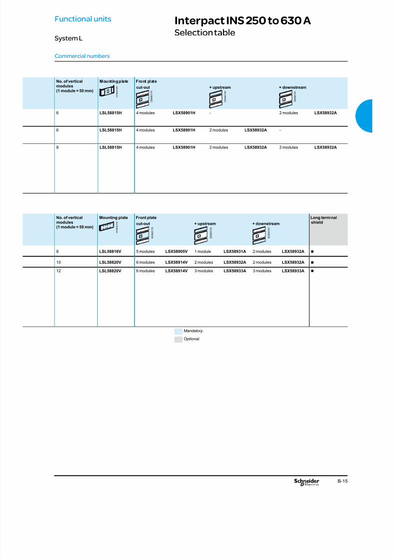
Interpact INS 250 to 630 ASelection table
Commercial numbers
Functional units
System L
No. of vertical
modules(1 module = 50 mm)
Mounting plate Front plate
cut-out + upstream + downstream
6 LSL58815H 4 modules LSX58901H - 2 modules LSX58932A
6 LSL58815H 4 modules LSX58901H 2 modules LSX58932A -
8 LSL58815H 4 modules LSX58901H 2 modules LSX58932A 2 modules LSX58932A
No. of verticalmodules(1 module = 50 mm)
Mounting plate Front plate Long terminalshieldcut-out + upstream + downstream
8 LSL58816V 5 modules LSX58905V 1 module LSX58931A 2 modules LSX58932A b
10 LSL58820V 6 modules LSX58914V 2 modules LSX58932A 2 modules LSX58932A b
12 LSL58820V 6 modules LSX58914V 3 modules LSX58933A 3 modules LSX58933A b
Mandatory.
Optional.
D D 8 0 0 1 7 9
D D 8 0 0 1 8 0
D D 8 0 0 1 8 1
D D 8 0 0 1 7 9
D D 8 0 0 1 8 0
D D 8 0 0 1 8 1
D D 8 0 0 1 7 8
D D 8 0 0 1 8 2

8/15/2019 Prisma iPM System L Catalogue 2011
http://slidepdf.com/reader/full/prisma-ipm-system-l-catalogue-2011 46/128B-16
Fupact INF 32 to 160 ASelection table
Commercial numbers
LIGHT
Accessories For the functional unit accessories, see page B-30~B-31.
D D 3 8 3 9 7 4
Functional units
System L
Vertical installationCircuit breaker No. of devices
per row
Front
connection
Control No. of pole
INF32 / 40 4 x 3P direct by cables front control 3P
INF63 3 x 3P direct by cables front control 3P
INF100 / 160 2 x 3P direct by cables front control 3P
Fupact INF32 / 40
Fupact INF100 / 160
D D 8 0 0 1 4 5
D D 8 0 0 1 4 4

8/15/2019 Prisma iPM System L Catalogue 2011
http://slidepdf.com/reader/full/prisma-ipm-system-l-catalogue-2011 47/128
8/15/2019 Prisma iPM System L Catalogue 2011
http://slidepdf.com/reader/full/prisma-ipm-system-l-catalogue-2011 48/128B-18
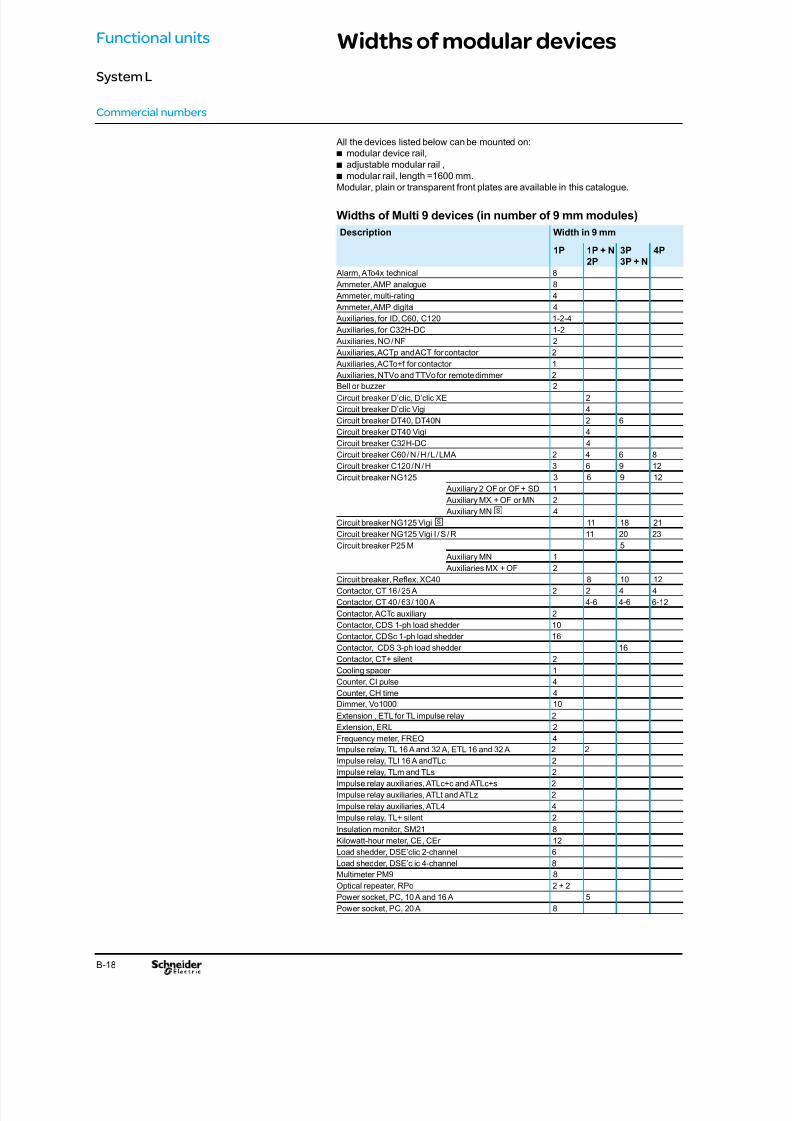
Widths of modular devices
Commercial numbers
All the devices listed below can be mounted on:
modular device rail,badjustable modular rail ,b
modular rail, length =1600 mm.bModular, plain or transparent front plates are available in this catalogue.
Widths of Multi 9 devices (in number of 9 mm modules)
Description Width in 9 mm
1P 1P + N
2P
3P
3P + N
4P
Alarm, ATo4x technical 8
Ammeter, AMP analogue 8
Ammeter, multi-rating 4
Ammeter, AMP digital 4
Auxiliaries, for ID, C60, C120 1-2-4
Auxiliaries, for C32H-DC 1-2
Auxiliaries, NO / NF 2
Auxiliaries, ACTp and ACT for contactor 2
Auxiliaries, ACTo+f for contactor 1
Auxiliaries, NTVo and TTVo for remote dimmer 2
Bell or buzzer 2
Circuit breaker D’clic, D’clic XE 2
Circuit breaker D’clic Vigi 4
Circuit breaker DT40, DT40N 2 6
Circuit breaker DT40 Vigi 4
Circuit breaker C32H-DC 4
Circuit breaker C60 / N / H / L / LMA 2 4 6 8
Circuit breaker C120 / N / H 3 6 9 12
Circuit breaker NG125 3 6 9 12
Auxiliary 2 OF or OF + SD 1
Auxiliary MX + OF or MN 2
Auxiliary MNs 4
Circuit breaker NG125 Vigis 11 18 21Circuit breaker NG125 Vigi I / S / R 11 20 23
Circuit breaker P25 M 5
Auxiliary MN 1
Auxiliaries MX + OF 2
Circuit breaker, Reex, XC40 8 10 12
Contactor, CT 16 / 25 A 2 2 4 4
Contactor, CT 40 / 63 / 100 A 4-6 4-6 6-12
Contactor, ACTc auxiliary 2
Contactor, CDS 1-ph load shedder 10
Contactor, CDSc 1-ph load shedder 16
Contactor, CDS 3-ph load shedder 16
Contactor, CT+ silent 2
Cooling spacer 1
Counter, CI pulse 4
Counter, CH time 4
Dimmer, Vo1000 10
Extension , ETL for TL impulse relay 2
Extension, ERL 2
Frequency meter, FREQ 4
Impulse relay, TL 16 A and 32 A, ETL 16 and 32 A 2 2
Impulse relay, TLI 16 A andTLc 2
Impulse relay, TLm and TLs 2
Impulse relay auxiliaries, ATLc+c and ATLc+s 2
Impulse relay auxiliaries, ATLt and ATLz 2
Impulse relay auxiliaries, ATL4 4
Impulse relay, TL+ silent 2
Insulation monitor, SM21 8
Kilowatt-hour meter, CE, CEr 12
Load shedder, DSE’clic 2-channel 6
Load shedder, DSE’clic 4-channel 8
Multimeter PM9 8Optical repeater, RPo 2 + 2
Power socket, PC, 10 A and 16 A 5
Power socket, PC, 20 A 8
Functional units
System L

8/15/2019 Prisma iPM System L Catalogue 2011
http://slidepdf.com/reader/full/prisma-ipm-system-l-catalogue-2011 49/128B-19
Widths of modular devices
Commercial numbers
Widths of Multi 9 devices (in number of 9 mm modules)
Description Width in 9 mm
1P 1P + N
2P
3P
3P + N
4P
Pushbuttons 2
Rccb, ID’clic 4
Rccb, ID’clic XE 4
Regulator, REGad1 / REGad2 12
Relay, RBN low level 2
Switch disconnector, INS 40 to 80 A 10 10
Switch disconnector, INS 100 to 160 A 15 15
Functional units
System L
8/15/2019 Prisma iPM System L Catalogue 2011
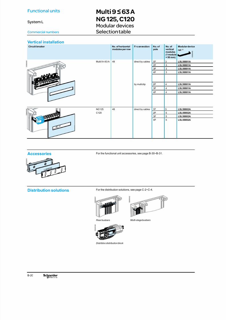
http://slidepdf.com/reader/full/prisma-ipm-system-l-catalogue-2011 50/128B-20
Vertical installationCircuit breaker No. of horizontal
modules per row
Fr connection No. of
pole
No. of
verticalmodules(1 module= 50 mm)
Modular device
rail (1)
Multi 9 ≤ 63 A 48 direct by cables 1P 3 LSL58801A
2P 3 LSL58801A
3P 3 LSL58801A
4P 3 LSL58801A
by multiclip 2P 4 LSL58801A
3P 4 LSL58801A
4P 4 LSL58801A
NG125 48 direct by cables 1P 5 LSL58802A
C120 2P 5 LSL58802A
3P 5 LSL58802A
4P 5 LSL58802A
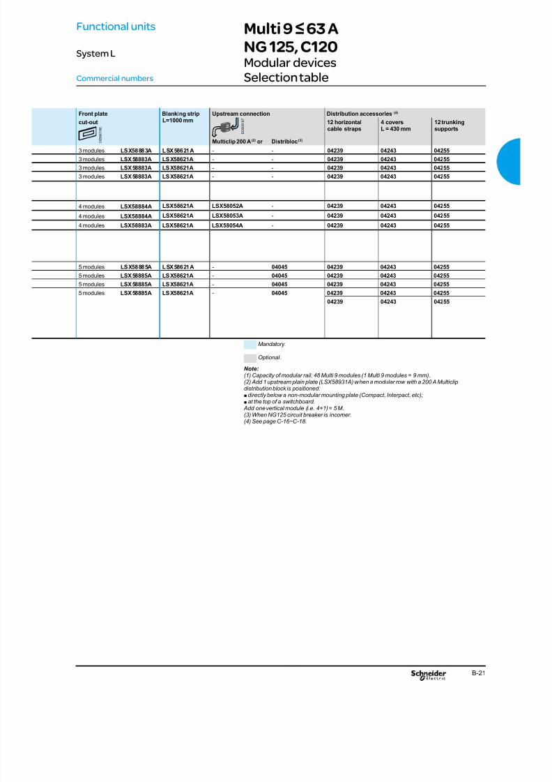
Multi 9 ≤ 63 ANG 125, C120Modular devicesSelection tableCommercial numbers
LUMIERE
Accessories For the functional unit accessories, see page B-30~B-31.
D D 8 0 0 0 0 8
D D 8 0 0 0 0 9
D D 8 0 0 0 4 0
D D 3 8 3 9 7 4
Distribution solutions
Rear busbars Multi-stage busbars
Distribloc distribution block
For the distribution solutions, see page C-2~C-4.
D D 8 0
0 0 0 1
D D 8 0 0 0 0 2
D D 3 8 1 3 0 8
Functional units
System L
8/15/2019 Prisma iPM System L Catalogue 2011
http://slidepdf.com/reader/full/prisma-ipm-system-l-catalogue-2011 51/128

8/15/2019 Prisma iPM System L Catalogue 2011
http://slidepdf.com/reader/full/prisma-ipm-system-l-catalogue-2011 52/128B-22
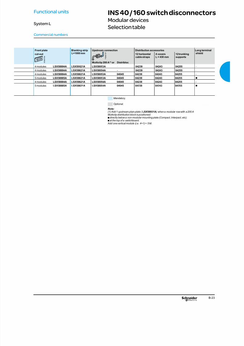
INS 40 / 160 switch disconnectorsModular devices
Selection table
Commercial numbers
LUMIERE
Accessories For the functional unit accessories, see page B-30~B-31.
D D 3 8 3 9 7 4
Distribution solutions
Rear busbars Multi-stage busbars
Distribloc distribution block
For the distribution solutions, see page C-2~C-4.
D D 8 0 0 0 0 1
D D 3 8 1 3 0 8
Functional units
System L
Vertical installationCircuit breaker No. of
horizontalmodulesper row
Front
connection
No. of
pole
No. of
verticalmodules(1 module= 50 mm)
Adjustable device rail
INS 40 / 63 / 80 48 direct by cables 3P 4 LSL58802A
4P 4 LSL58802A
INS 100 / 125 / 160 48 direct by cables 3P 4 LSL58802A
5 LSL58802A
4P 4 LSL58802A
5 LSL58802A
D D 8 0 0 0 1 0
D D 8 0 0 0 3 9
8/15/2019 Prisma iPM System L Catalogue 2011
http://slidepdf.com/reader/full/prisma-ipm-system-l-catalogue-2011 53/128

8/15/2019 Prisma iPM System L Catalogue 2011
http://slidepdf.com/reader/full/prisma-ipm-system-l-catalogue-2011 54/128B-24
GV2+Series D contactor NO. of vertical modules(1 module=50mm)
GV2 + contactor 5
5
Series D contactors <=95A NO. of vertical modules(1 module=50mm)
Series D contactor <=40A(Side by side)
3
Series D contactor <=95A
(Side by side)
4
GV2 circuit breakers NO. of vertical modules(1 module=50mm)
GV2 circuit breakers(Side by side)
3
Vertical installationCircuit breaker + Contactors up to 45kw NO. of vertical modules
(1 module=50mm)
NSX100-MA 6
Soft starter up to 11kw NO. of vertical modules(1 module=50mm)
ATS48D17 ATS48D22 ATS48D32 ATS48D38 ATS48D47
8
8
ATS48D62 ATS48D75
ATS48D88 ATS48C11
8
LV/LV transformers NO. of vertical modules(1 module=50mm)
LV/LV transformers 4
8
12
Accessories For the function unit and front plate accessories, see page B-30~B-31.
LIGHT
D D 8 0 0 5 2 7
D D 8 0 0 5 2 4
D D 8 0 0 5 2 6
D D 8 0 0 5 2 5
D D 8 0 0 0 4 1
D D 8 0 0 5 2 3
D D 8 0 0 5 2 2
D D 8 0 0 5 2 1
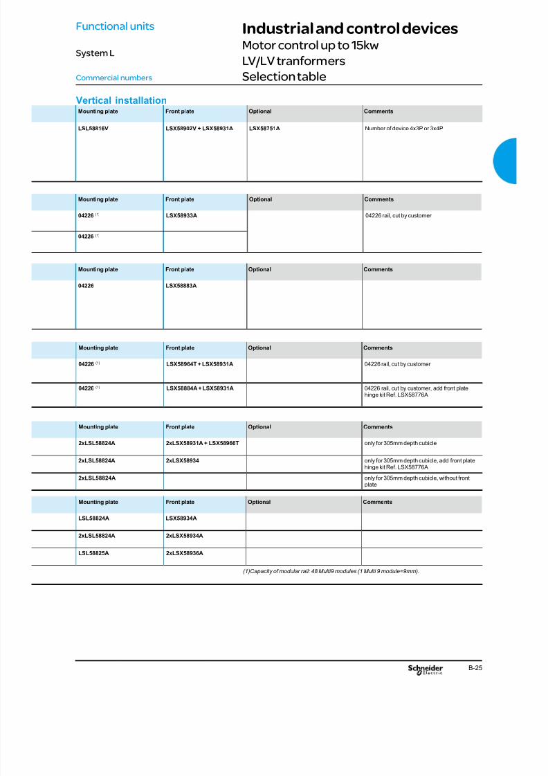
Industrial and control devicesMotor control up to 15kw
LV/LV tranformers
Selection tableCommercial numbers
Functional units
System L
8/15/2019 Prisma iPM System L Catalogue 2011
http://slidepdf.com/reader/full/prisma-ipm-system-l-catalogue-2011 55/128B-25
Mounting plate Front plate Optional Comments
04226 (1) LSX58964T + LSX58931A 04226 rail, cut by customer
04226 (1) LSX58884A + LSX58931A 04226 rail, cut by customer, add front platehinge kit Ref. LSX58776A
Mounting plate Front plate Optional Comments
04226 (1) LSX58933A 04226 rail, cut by customer
04226 (1)
Mounting plate Front plate Optional Comments
04226 LSX58883A
Vertical installationMounting plate Front plate Optional Comments
LSL58816V LSX58902V + LSX58931A LSX58751A Number of device 4x3P or 3x4P
Mounting plate Front plate Optional Comments
2xLSL58824A 2xLSX58931A + LSX58966T only for 305mm depth cubicle
2xLSL58824A 2xLSX58934 only for 305mm depth cubicle, add front platehinge kit Ref. LSX58776A
2xLSL58824A only for 305mm depth cubicle, without front
plate
Mounting plate Front plate Optional Comments
LSL58824A LSX58934A
2xLSL58824A 2xLSX58934A
LSL58825A 2xLSX58936A
Industrial and control devicesMotor control up to 15kw
LV/LV tranformers
Selection tableCommercial numbers
(1)Capacity of modular rail: 48 Multi9 modules (1 Multi 9 module=9mm).
Functional units
System L

8/15/2019 Prisma iPM System L Catalogue 2011
http://slidepdf.com/reader/full/prisma-ipm-system-l-catalogue-2011 56/128B-26
Human / Machine interface72 x 72 and 96 x 96 mm devices
Presentation
Commercial numbers
Dedicated front plates are available for 72 x 72 mm and 96 x 96 mm devices.
It is installed in the device zone.
Blanking plate are available to blank off any unused locations.They have knock-outs to t lights, push-buttons, etc..
72 x 72 mm and 96 x 96 mm devices can be directly adapted on plain door: cut-out to
be made by the customer.
The degree of protection for installed devices is IP30.
To maintain the IP54 degree of protection, the devices must be installed behind a
transparent door.
Presentation
Front plate of 72x72 mm diameter for 6 devices.
Front plate of 96x96 mm diameter for 4 devices.
D D 8 0 0 0 1 2
D D 8 0 0 0 1 3
Functional units
System L

8/15/2019 Prisma iPM System L Catalogue 2011
http://slidepdf.com/reader/full/prisma-ipm-system-l-catalogue-2011 57/128B-27
Human / Machine interface72 x 72 and 96 x 96 mm devices
Presentation
Commercial numbers
Designation Com. no.
Metal front plate with cut-outs, 3 modules (for six 72 x 72 mm devices) LSX58956A
Blanking plate (for 72 x 72 mm hole) LSX58961A
72 x 72 mm measurement devices
The blanking plates have knock-outs:3 holes, 22 mm diameter,b1 hole, 45 x 45 mm.b
Designation Com. no.
Metal front plate with cut-outs, 3 modules (for four 96 x 96 mm devices) LSX58955A
Blanking plate (for 96 x 96 mm hole) LSX58960A
96 x 96 mm measurement
devices
The blanking plates have knock-outs:3 holes, 22 mm diameter,b1 hole, 45 x 45 mm,b1 hole, 72 x 72 mm.b
D D
3 8 1 6 8 9
D D 3 8 2 6 3 7
D D 3 8 1 7 1 1
D D 3 8 2 6 3 7
Functional units
System L

8/15/2019 Prisma iPM System L Catalogue 2011
http://slidepdf.com/reader/full/prisma-ipm-system-l-catalogue-2011 58/128B-28
Other devicesFor all type of device
Selection table
Commercial numbers
Designation Depth behindfront plate (mm)
Useful length(mm)
Com. no.
Adjustable modular device rail 47 to 114 432 LSL58802A
2 modular device rails 144 1600 04226
L modular device rail 49 1600 LSL58801A
Installation on modular rail
Adjustable modular device rail (LSL58802A).
Modular rail, L=1600 mm (04226).
Installation on slotted plate Designation No. of vertical modules(1 module = 50 mm)
Depth behind frontplate (mm)
Com. no.
Slotted mounting plate 4 122 LSL58824A
12 122 LSL58825A
Clip-nuts for slotted mounting plates (for device xing)Designation Com. no.
20 M4 clip-nuts for slotted mounting plate 03180
20 M5 clip-nuts for slotted mounting plate 03181
20 slotted mounting plate clip-nuts M6 03182
Installation on plain plate Designation No. of vertical modules(1 module = 50 mm)
Depth behind frontplate (mm)
Com. no.
Plain mounting plate 4 116 LSL58826A
12 116 LSL58827A
Cut-out front plate for modular
devices
Designation No. of vertical modules(1 module = 50 mm)
Com. no.
Front plate for modular devices 3 LSX58883A
4 LSX58884A
5 LSX58885A
Blanking strip (for blanking off unused locations)Designation Com. no.
Blanking strip modular device, L = 1000 mm LSX58621A
D D 3 8 1 3 1 2
D D 8 0 0 0 4 4
D D 3 8 0 8 0 5
D D 8 0 0 1 6 1
D D 8 0 0 0 4 2
D D
8 0 0 3 9 3
D D 8 0 0 3 9 4
Functional units
System L

8/15/2019 Prisma iPM System L Catalogue 2011
http://slidepdf.com/reader/full/prisma-ipm-system-l-catalogue-2011 59/128B-29
Reserve spaceSelection table
Commercial numbers
Plain front plate
Transparent front plate
Designation No. of vertical modules (1 module = 50 mm) Cat. no.
Plain front plate 1 LSX58931A
2 LSX58932A3 LSX58933A
4 LSX58934A
6 LSX58936A
Designation No. of vertical modules (1 module = 50 mm) Cat. no.
Transparent front plate 4 LSX58964T
6 LSX58966T
D D 3 8 1 5 8 3
D D 3 8 1 5 8 2
Functional units
System L

8/15/2019 Prisma iPM System L Catalogue 2011
http://slidepdf.com/reader/full/prisma-ipm-system-l-catalogue-2011 60/128B-30
Functional unit accessoriesSelection table
The angle brackets are used for:
vertical mounting of the earth / neutral bar in the duct,bmounting of the modular rail L = 1600 mm (com. no. 04226).b
Designation Com. no.
2 universal angle brackets 03581
The hexagonal spacers are used for:
the raising and the mounting of the modular rail,b
the raising and the mounting of the earth / neutral bar.bDesignation Com. no.
4 M6 hexagonal spacers H = 9 mm 03195
H = 23 mm 03196
H = 55 mm 03197
Universal angle bracket
Hexagonal spacers
Designation Com. no.
Front plate hinge kit LSX58776A
Hinge kit
Lead-sealable screws For restricted access, the front plate can be sealed as visual checking.
Designation Com. no.
4 front plate lead-sealable screws LSX58777A
The blanking strips are used to ll the space on the cut-out front plates.
Designation Com. no.
Blanking strip modular device, L = 1000 mm LSX58621A
Blanking strip CVS/NSX250/INS250, L = 148 mm LSX58751A
Blanking strip EZC250, L = 1000 mm LSX58752A
Blanking strip
D D 8 0 0 3 9 0
D D 8 0 0 1 6 0
D D 8 0 0 0 1 4
D D 8 0 0 0 1 5
D D 3 8 1 5 7 7
D D 8 0 0 1 5
9
Commercial numbers
Functional units
System L
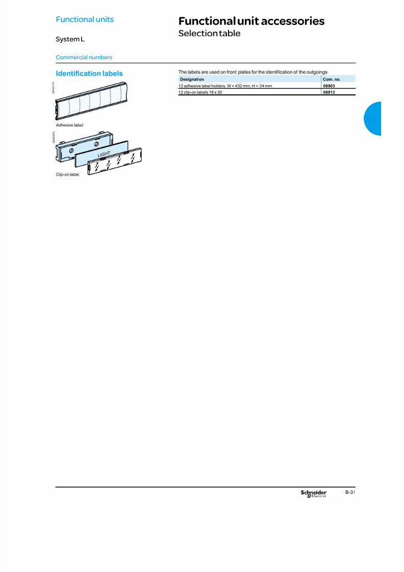
8/15/2019 Prisma iPM System L Catalogue 2011
http://slidepdf.com/reader/full/prisma-ipm-system-l-catalogue-2011 61/128B-31
Functional unit accessoriesSelection table
LIGHT
Identication labels The labels are used on front plates for the identication of the outgoings.
Designation Com. no.
12 adhesive label holders, W = 432 mm, H = 24 mm 08903
12 clip-on labels 18 x 35 08913
Clip-on label.
Adhesive label.
D D 3 8 3 9 7 4
D D 3
8 1 7 1 5
Commercial numbers
Functional units
System L

8/15/2019 Prisma iPM System L Catalogue 2011
http://slidepdf.com/reader/full/prisma-ipm-system-l-catalogue-2011 62/128C-2

8/15/2019 Prisma iPM System L Catalogue 2011
http://slidepdf.com/reader/full/prisma-ipm-system-l-catalogue-2011 63/128C-1
Contents
Description C-2Overview of distribution solutions C-2Different type of distribution solutions C-4
Busbars C-5Multi-stage busbars C-5
Rear busbars C-6
Distribution blocks C-7Distribloc distribution block C-7
Polybloc distribution block C-8
Multiclip distribution block C-9
Multi-stage current distribution blocks C-10
Comb busbars C-11
Commercial numbers C-12Busbars from 160 to 630 A C-12Distribution blocks C-14
Distribution accessories C-16Partitioning C-19
Distribution
System L
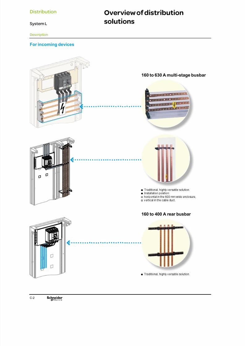
8/15/2019 Prisma iPM System L Catalogue 2011
http://slidepdf.com/reader/full/prisma-ipm-system-l-catalogue-2011 64/128

8/15/2019 Prisma iPM System L Catalogue 2011
http://slidepdf.com/reader/full/prisma-ipm-system-l-catalogue-2011 65/128C-3
Overview of distribution
solutions
Description
For rows of modular devices
125 A Distribloc
80 to 125 A comb busbars
200 A Multiclip
D D 8 0 0 1 5 8
Distribution
System L
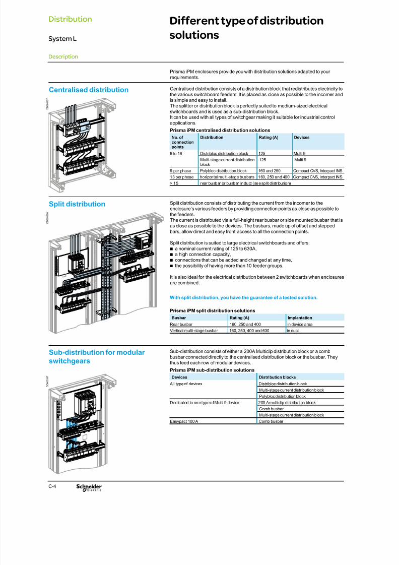
8/15/2019 Prisma iPM System L Catalogue 2011
http://slidepdf.com/reader/full/prisma-ipm-system-l-catalogue-2011 66/128C-4
Different type of distribution
solutions
Prisma iPM enclosures provide you with distribution solutions adapted to yourrequirements.
Centralised distribution Centralised distribution consists of a distribution block that redistributes electricity tothe various switchboard feeders. It is placed as close as possible to the incomer andis simple and easy to install.The splitter or distribution block is perfectly suited to medium-sized electricalswitchboards and is used as a sub-distribution block.It can be used with all types of switchgear making it suitable for industrial controlapplications.
Prisma iPM centralised distribution solutions
No. ofconnectionpoints
Distribution Rating (A) Devices
6 to 16 Distribloc distribution block 125 Multi 9
Multi-stage current distributionblock
125 Multi 9
9 per phase Polybloc distribution block 160 and 250 Compact CVS, Interpact INS
13 per phase horizontal multi-stage busbars 160, 250 and 400 Compact CVS, Interpact INS> 15 rear busbar or busbar in duct (see split distr ibution)
Split distribution Split distribution consists of distributing the current from the incomer to theenclosure’s various feeders by providing connection points as close as possible tothe feeders.The current is distributed via a full-height rear busbar or side mounted busbar that isas close as possible to the devices. The busbars, made up of offset and steppedbars, allow direct and easy front access to all the connection points.
Split distribution is suited to large electrical switchboards and offers:a nominal current rating of 125 to 630A,b
a high connection capacity,b
connections that can be added and changed at any time,b
the possibility of having more than 10 feeder groups.b
It is also ideal for the electrical distribution between 2 switchboards when enclosuresare combined.
With split distribution, you have the guarantee of a tested solution.
Prisma iPM split distribution solutions
Busbar Rating (A) Implantation
Rear busbar 160, 250 and 400 in device area
Vertical multi-stage busbar 160, 250, 400 and 630 in duct
Sub-distribution for modularswitchgears
Sub-distribution consists of either a 200A Multiclip distribution block or a combbusbar connected directly to the centralised distribution block or the busbar. Theythus feed each row of modular devices.
Prisma iPM sub-distribution solutions
Devices Distribution blocks
All type of devices Distribloc distribution block
Multi-stage current distribution block
Polybloc distribution block
Dedicated to one type of Multi 9 device 200 A multiclip distribution block
Comb busbar
Multi-stage current distribution block
Easypact 100 A Comb busbar
D D 8 0 0 1 5 7
D D 8 0 0 3 9 7
D D 8 0 0 3 9 8
Description
Distribution
System L
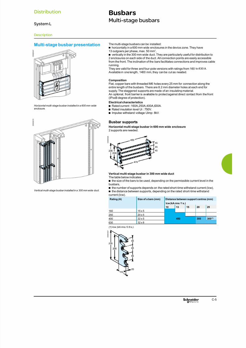
8/15/2019 Prisma iPM System L Catalogue 2011
http://slidepdf.com/reader/full/prisma-ipm-system-l-catalogue-2011 67/128C-5
BusbarsMulti-stage busbars
The multi-stage busbars can be installed:horizontally in a 600 mm wide enclosures in the device zone. They haveb
13 outgoers per phase, max. 50 mm2,
vertically in the 300 mm wide duct. They are particularly useful for distribution tob
2 enclosures on each side of the duct. All connection points are easily accessiblefrom the front. The inclination of the bars facilitates connections and improves cablerunning.They are valid for three and four-pole versions with ratings from 160 to 630 A. Available in one length, 1400 mm, they can be cut as needed.
Composition
Flat, copper bars with threaded M6 holes every 25 mm for connection along theentire length of the busbars. There are 8.2 mm diameter holes at each end forsupply. The staggered supports are made of an insulating material. An optional, front barrier is available to protect against direct contact from the front(IPxxB degree of protection).
Electrical characteristics
Rated current :160A,250A,400A,630A.b
Rated insulation level Ui : 750V.b
Impulse withstand voltage Uimp: 8kV.b
Busbar supports
Horizontal multi-stage busbar in 600 mm wide enclosure
2 supports are needed.
Multi-stage busbar presentation
Vertical multi-stage busbar in 300 mm wide duct
The table below indicates:the size of the bars to be used, depending on the permissible current level in theb
busbars,the number of supports depends on the rated short-time withstand current (Icw),b
the distance between supports, depending on the rated short-time withstandb
current (Icw).
Rating (A) Size of a bars (mm) Distance between support centres (mm)
Icw (kA rms / 1 s.)
10 13 15 20 25
160 15 x 5
250 20 x 5
400 32 x 5 450 300 300(1)
630 32 x 8
(1) Icw (kA rms / 0.6 s.).
Horizontal multi-stage busbar installed in a 600 mm wide
enclosure.
Vertical multi-stage busbar installed in a 300 mm wide duct.
D D 8 0 0 0 2 8
D D 8 0 0 0 2 7
D D 8
0 0 0 4 7
D D 8 0 0 0 1 9
Description
Distribution
System L

8/15/2019 Prisma iPM System L Catalogue 2011
http://slidepdf.com/reader/full/prisma-ipm-system-l-catalogue-2011 68/128C-6
BusbarsRear busbars
The rear busbar is installed in a 600 mm wide enclosures and is mounted directly onthe uprights of the frameworks.It is valid for three or four-pole versions with ratings from 160 to 400 A.
Available in one length, 1400 mm, the bars can be cut as needed.The connection with a Compact or Interpact incoming device occupies two verticalmodules ( 50 mm each).
Composition
Flat, copper bars with threaded M6 holes every 25 mm for connection along theentire length of the busbars.The insulating supports can receive a fth bar, 15 x 5 mm or 20 x 5 mm, to create an
earth bar.
Installation
The busbars are mounted directly on the functional uprights of a 600 mm wideenclosure.
Connection
16 mmb2 to 50 mm2 exible cables, with crimped lugs,
insulated exible bars.b
Electrical characteristicsRated peak withstand current Ipk (kÂ)b
v 30 k for 160 A busbars,v 40 k for 250 A busbars,v 55 k for 400 A busbars.
Rated insulation level Ui = 1000 V.b
Rear busbars presentation
Busbar calculation Busbar size and distance between supports
The table below indicates:the size of the bars to be used, depending on the permissible current level in theb
busbars,the distance between supports, depending on the rated short-time withstandb
current (Icw).Rating (A) Size of a bars (mm) Distance between support centres(1) (mm)
Icw (kA rms / 1 s.
10 13 15 20 25160 15 x 5
250 20 x 5 450
400 32 x 5 300 250
(1) Multiclip 200 A distribution blocks equipped with connections (04029) can be used asintermediate supports (200 mm max. distance between centres) in addition to the top and bottomsupports.
Rear busbar installed in a 600 mm wide enclosure.
D D 8 0 0 0 1 8
Description
Distribution
System L

8/15/2019 Prisma iPM System L Catalogue 2011
http://slidepdf.com/reader/full/prisma-ipm-system-l-catalogue-2011 69/128C-7
Distribution blocksDistribloc distribution block
Downstream circuits are connected from the front, to spring terminals.Contact pressure automatically adapts to the size of the conductor. It does notdepend on the operator.Contacts are insensitive to vibrations and thermal variations.Only one cable (exible or rigid, without a metal ferrule) can be inserted in a spring
terminal.Degree of protection: IPxxB.
Advantages
A reliable electrical connection, no maintenance required (tightness guaranteedb
over time).Very fast connection.b
Easy phase balancing.b
Rewiring is very easy if the switchboard is expanded or modied.b
The spring terminals
Distribloc distribution block
presentation
The Distribloc distribution block is particularly suited to small and medium-sizedenclosures. It gives lots of exibility when there are few feeders. It provides safety
and makes maintenance easy.
It has been optimised for enclosures containing mainly modular devices. It can beused equally as a main or sub-distribution block, or for industrial control applications.It is easily installed by simply cl ipping it onto the modular rail. It can also be xed to
the backplate for industrial control applications.
The Distribloc distribution block provides you with:safetyb
v IPxxB protection of live conductors,v tightening quality guaranteed by spring terminals,v electrical performance levels adapted to your needs,
simplicityb
v easy installation and wiring,v simple choice depending on device rating,
exibilityb
v selection of combinations,v
possibility of adding and changing feeders.
Composition
The four-pole distribution block is made up of:a fully insulated, one-piece distribution block complying with the degree ofb
protection IPxxB (protection against direct contacts),a modular cover.b
The design of the front (45 mm nose) blends perfectly into a row comprising modulardevices.
Electrical characteristics
Rated insulation level: Ui = 750 V.b
Rated operational current Ie (40°C):b
v 125 A for the 125 A Distribloc,Short-circuit withstand current: the reinforced breaking capacity due to cascadingb
in circuit-breaker combinations is maintained. The worst-case situations have been
tested.Complies with the low-voltage device standard IEC 60947.7.1 and / orb
IEC 61439.1Impulse withstand voltage Uimp = 8 kV.b
Supply
Tunnel terminal on 125 A Distribloc 125 for 6 to 35 mmb2 exible cables (10 to
35mm2 rigid cables).
Distribution
Spring terminals:b
v 2 outgoers from 1 to 10 mm2, exible or rigid,
v 3 outgoers from 1 to 6 mm2, exible or rigid,
v 7 outgoers from 1 to 4 mm2, exible or rigid.
Tunnel terminals:b
v 1 outgoer from 4 to 16 mm2, exible (4 to 25 mm2 rigid).
Supply
An identication label.b
Adhesive labels for phase identication.b
Installation
Clipped onto a modular rail.b
Width occupied is 12 modules (9 mm each).b
Screwed to plain or slotted backplate. Distances between centres = 100 x 75 mm.b
Distribloc distribution block supplying the modular devices.
Dimensions
D D 3 8 1 3 9 9
D D 3 8 1 6 0 8
D D 3 8 1 6 0 9
D D 8 0 0 4 6 4
Description
Distribution
System L

8/15/2019 Prisma iPM System L Catalogue 2011
http://slidepdf.com/reader/full/prisma-ipm-system-l-catalogue-2011 70/128C-8
Distribution blocksPolybloc distribution block
38
70
95
The Polybloc distribution block is particularly suited to small and medium-sizedenclosures. It gives lots of exibility when there are few feeders. It provides safety
and makes maintenance easy.
It has been optimised for enclosures containing mainly modular devices. It can beused equally as a main or sub-distribution block.
The Polybloc is available in two versions :the 250 A Polybloc distribution block is designed for installation directlyb
downstream of Compact circuit breakers and Interpact switch-disconnectors devicesup to 250 A. It can be rapidly mounted in the vertical position. Electrical connectionsare made directly to the device terminals. The connection terminals are slanted tofacilitate cable entry and not exceed the bending radius of the exible and rigid
cables,the 160 A Polybloc is made up of individual elements that can be used alone orb
with others to make two-pole, three-pole or four-pole distribution blocks.Mounting is very fast. It clips onto a modular rail and is supplied by cables via a tunnelterminal. The connection spring terminals are slanted to facilitate cable entry andbending of the exible and rigid cables. It is supplied with a cover that also guides the
cables.Electrical characteristics
Rated insulation level Ui = 750 V.b
Short-circuit withstand current: the reinforced breaking capacity due to cascadingb
in circuit-breaker combinations is maintained. The worst-case situations were tested.Impulse withstand voltage Uimp = 8 kV.b
Supply
250 A Polybloc distribution block:b
v directly to the terminals of the Compact NSX and Interpact INS devices up to250 A.
160 A Polybloc distribution block:b
v direct to a tunnel terminal, for cables up to 70 mm2.
Distribution
250 A Polybloc distribution block:b
v via cables, up to six 10 mm2 cables and three 16 mm2 cables per phase.
160 A Polybloc distribution block:b
v via cables, up to six 16 mm2 cables.
Installation
250 A Polybloc distribution block:b
It is mounted downstream of vertically mounted Compact NS100 / 250 andb
NSX100 / 250 and Interpact INS250 devices in the enclosures. The Polybloc ismounted on the modular device rail (LSL58801A).
160 A Polybloc distribution block:b
v the blocks clip onto a modular rail.
Dimensions
Polybloc distribution block
presentation
Downstream circuits are connected from the front, to spring terminals.Contact pressure automatically adapts to the size of the conductor. It does notdepend on the operator.Contacts are insensitive to vibrations and thermal variations.Only one cable (exible or rigid, without a metal ferrule) can be inserted in a spring
terminal.Degree of protection: IPxxB.
Advantages A reliable electrical connection, no maintenance required (tightness guaranteedb
over time).Very fast connection.b
Easy phase balancing.b
Rewiring is very easy if the switchboard is expanded or modied.b
The spring terminals
D D 3 8 1 3 9 9
160 A Polybloc distribution block installedin a 600 mm wide enclosure.
250 A Polybloc distribution block installedin a 600 mm wide enclosure.
250 A Polybloc distribution block 160 A Polybloc distribution block
D D 8 0 0 1 4 7
D D 8 0 0 4 4 1
Description
Distribution
System L
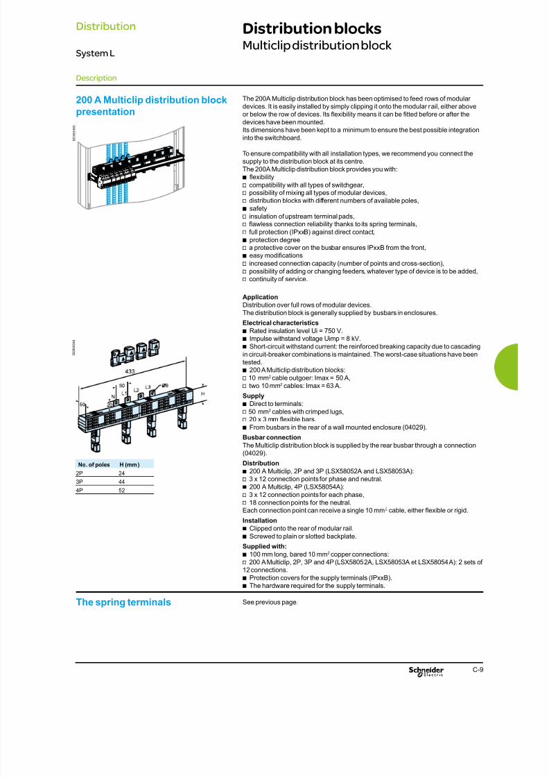
8/15/2019 Prisma iPM System L Catalogue 2011
http://slidepdf.com/reader/full/prisma-ipm-system-l-catalogue-2011 71/128C-9
Distribution blocksMulticlip distribution block
The spring terminals
The 200A Multiclip distribution block has been optimised to feed rows of modulardevices. It is easily installed by simply clipping it onto the modular rail, either aboveor below the row of devices. Its exibility means it can be tted before or after the
devices have been mounted.Its dimensions have been kept to a minimum to ensure the best possible integrationinto the switchboard.
To ensure compatibility with all installation types, we recommend you connect thesupply to the distribution block at its centre.The 200A Multiclip distribution block provides you with:
exibilityb
v compatibility with all types of switchgear,v possibility of mixing all types of modular devices,v distribution blocks with different numbers of available poles,
safetyb
v insulation of upstream terminal pads,v awless connection reliability thanks to its spring terminals,
v full protection (IPxxB) against direct contact,
protection degreeb
v a protective cover on the busbar ensures IPxxB from the front,easy modicationsb
v increased connection capacity (number of points and cross-section),v possibility of adding or changing feeders, whatever type of device is to be added,v continuity of service.
Application
Distribution over full rows of modular devices.The distribution block is generally supplied by busbars in enclosures.
Electrical characteristics
Rated insulation level Ui = 750 V.b
Impulse withstand voltage Uimp = 8 kV.b
Short-circuit withstand current: the reinforced breaking capacity due to cascadingb
in circuit-breaker combinations is maintained. The worst-case situations have been
tested.200 A Multiclip distribution blocks:b
v 10 mm2 cable outgoer: Imax = 50 A,v two 10 mm2 cables: Imax = 63 A.
Supply
Direct to terminals:b
v 50 mm2 cables with crimped lugs,v 20 x 3 mm exible bars.
From busbars in the rear of a wall mounted enclosure (04029).b
Busbar connection
The Multiclip distribution block is supplied by the rear busbar through a connection(04029).
Distribution
200 A Multiclip, 2P and 3P (LSX58052A and LSX58053A):b
v 3 x 12 connection points for phase and neutral.
200 A Multiclip, 4P (LSX58054A):b
v 3 x 12 connection points for each phase,v 18 connection points for the neutral.Each connection point can receive a single 10 mm2 cable, either exible or rigid.
Installation
Clipped onto the rear of modular rail.b
Screwed to plain or slotted backplate.b
Supplied with:
100 mm long, bared 10 mmb2 copper connections:
v 200 A Multiclip, 2P, 3P and 4P (LSX58052A, LSX58053A et LSX58054A): 2 sets of12 connections.
Protection covers for the supply terminals (IPxxB).b
The hardware required for the supply terminals.b
200 A Multiclip distribution block
presentation
See previous page.
No. of poles H (mm)
2P 24
3P 44
4P 52
D D 3 8 3 4 8 3
D D 8 0 0 0 4 8
Description
Distribution
System L

8/15/2019 Prisma iPM System L Catalogue 2011
http://slidepdf.com/reader/full/prisma-ipm-system-l-catalogue-2011 72/128C-10
Distribution blocksMulti-stage current distribution blocks
The multi-stage current distribution block is easy to install and can be either clippedonto the modular rail or xed to a solid or perforated mounting plate.
Electrical characteristics
Rated operating current: Ie (40 °C) = 125 A.b
Rated insulation level Ui = 500 V.b
Rated short-time withstand current Icw = 3.5 kA rms / 1 s.b
Peak withstand current Ipk = 20 kÂ.b
Impulse withstand voltage Uimp = 8 kV.b
Supply
Connected with exible or rigid cable with or without crimped lugs.b
Installation
Clipped onto the modular rail.b
Screwed to plain or slotted backplate.b
Supplied with:
transparent, insulating cover,b
mounting hardware.b
Dimensions
Multi-stage current distribution
block presentation
D D 3 8 2 8 1 3
E 1 9 4 5 3
Description
Distribution
System L
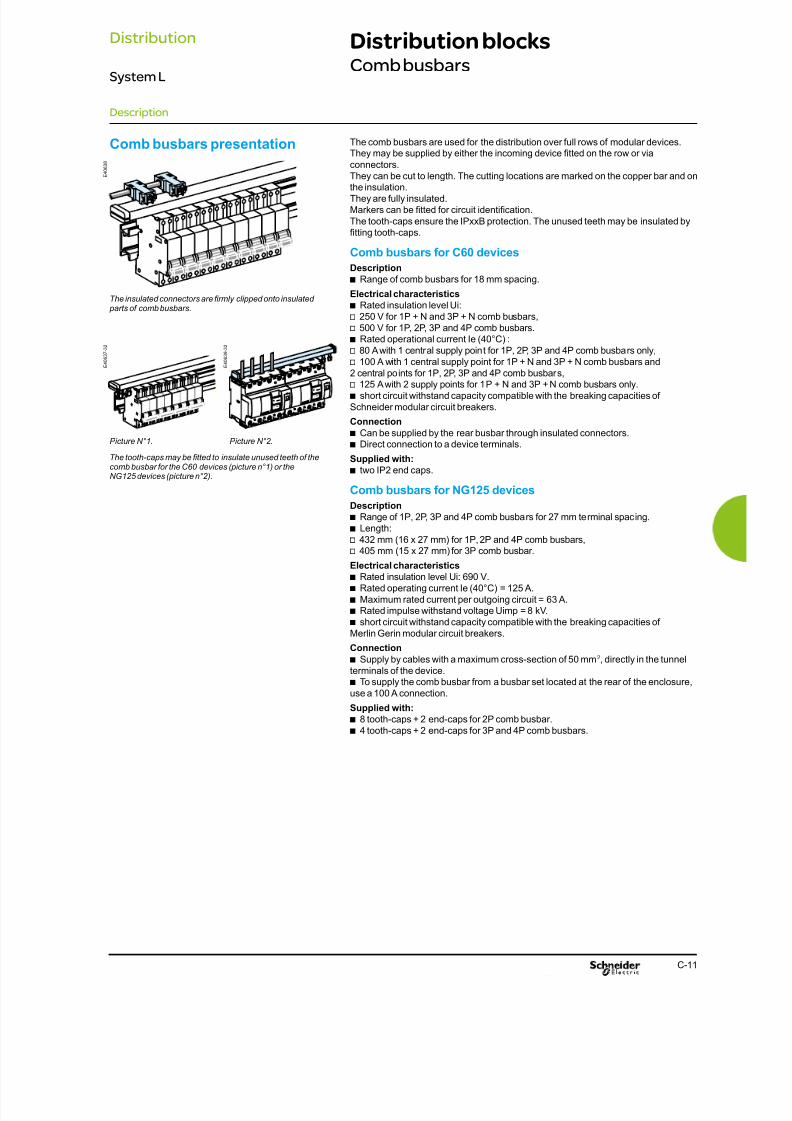
8/15/2019 Prisma iPM System L Catalogue 2011
http://slidepdf.com/reader/full/prisma-ipm-system-l-catalogue-2011 73/128C-11
Distribution blocksComb busbars
I . O N
I . O N
The comb busbars are used for the distribution over full rows of modular devices.They may be supplied by either the incoming device tted on the row or via
connectors.
They can be cut to length. The cutting locations are marked on the copper bar and onthe insulation.They are fully insulated.Markers can be tted for circuit identication.
The tooth-caps ensure the IPxxB protection. The unused teeth may be insulated bytting tooth-caps.
Comb busbars for C60 devices
Description
Range of comb busbars for 18 mm spacing.b
Electrical characteristics
Rated insulation level Ui:b
v 250 V for 1P + N and 3P + N comb busbars,v 500 V for 1P, 2P, 3P and 4P comb busbars.
Rated operational current Ie (40°C) :b
v 80 A with 1 central supply point for 1P, 2P, 3P and 4P comb busbars only,v 100 A with 1 central supply point for 1P + N and 3P + N comb busbars and2 central points for 1P, 2P, 3P and 4P comb busbars,v 125 A with 2 supply points for 1P + N and 3P + N comb busbars only.
short circuit withstand capacity compatible with the breaking capacities ofb
Schneider modular circuit breakers.
Connection
Can be supplied by the rear busbar through insulated connectors.b
Direct connection to a device terminals.b
Supplied with:
two IP2 end caps.b
Comb busbars for NG125 devices
Description
Range of 1P, 2P, 3P and 4P comb busbars for 27 mm terminal spacing.b
Length:b
v 432 mm (16 x 27 mm) for 1P, 2P and 4P comb busbars,v 405 mm (15 x 27 mm) for 3P comb busbar.
Electrical characteristics
Rated insulation level Ui: 690 V.b
Rated operating current Ie (40°C) = 125 A.b
Maximum rated current per outgoing circuit = 63 A.b
Rated impulse withstand voltage Uimp = 8 kV.b
short circuit withstand capacity compatible with the breaking capacities ofb
Merlin Gerin modular circuit breakers.
Connection
Supply by cables with a maximum cross-section of 50 mmb2, directly in the tunnel
terminals of the device.To supply the comb busbar from a busbar set located at the rear of the enclosure,b
use a 100 A connection.
Supplied with:
8 tooth-caps + 2 end-caps for 2P comb busbar.b
4 tooth-caps + 2 end-caps for 3P and 4P comb busbars.b
Comb busbars presentation
The insulated connectors are rmly clipped onto insulated parts of comb busbars.
The tooth-caps may be tted to insulate unused teeth of thecomb busbar for the C60 devices (picture n°1) or theNG125 devices (picture n°2).
Picture N°1. Picture N°2.
E 4 0 6 3 8
E 4 0 6 3 7 - 3 2
E 4 0 6 3 9 - 3 2
Description
Distribution
System L
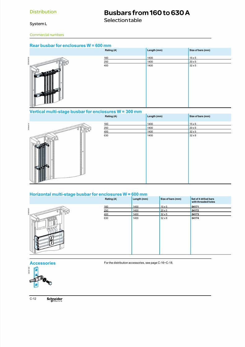
8/15/2019 Prisma iPM System L Catalogue 2011
http://slidepdf.com/reader/full/prisma-ipm-system-l-catalogue-2011 74/128C-12
Rear busbar for enclosures W = 600 mmRating (A) Length (mm) Size of bars (mm)
160 1400 15 x 5
250 1400 20 x 5
400 1400 32 x 5
Vertical multi-stage busbar for enclosures W = 300 mmRating (A) Length (mm) Size of bars (mm)
160 1400 15 x 5
250 1400 20 x 5
400 1400 32 x 5
630 1400 32 x 8
Horizontal multi-stage busbar for enclosures W = 600 mmRating (A) Length (mm) Size of bars (mm) Set of 4 drilled bars
with threaded holes
160 1400 15 x 5 04171
250 1400 20 x 5 04172
400 1400 32 x 5 04173
630 1400 32 x 8 04174
Busbars from 160 to 630 ASelection table
Commercial numbers
D D 3 8 0 0 0 1 8
D D 8 0 0 0 1 9
D D 8 0 0 0 4 7
Accessories For the distribution accessories, see page C-16~C-18.
D D 3 8 1 3 9 8
Distribution
System L
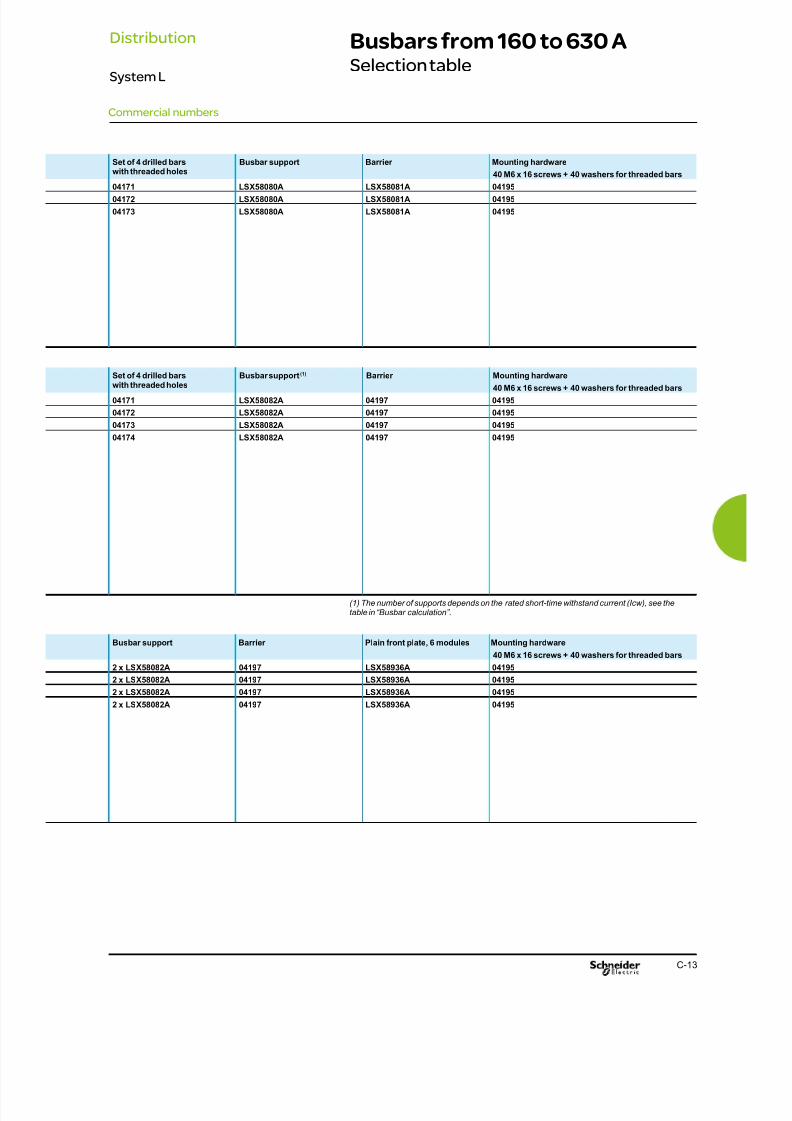
8/15/2019 Prisma iPM System L Catalogue 2011
http://slidepdf.com/reader/full/prisma-ipm-system-l-catalogue-2011 75/128C-13
Busbars from 160 to 630 ASelection table
Commercial numbers
Set of 4 drilled bars
with threaded holes
Busbar support Barrier Mounting hardware
40 M6 x 16 screws + 40 washers for threaded bars04171 LSX58080A LSX58081A 04195
04172 LSX58080A LSX58081A 04195
04173 LSX58080A LSX58081A 04195
Set of 4 drilled barswith threaded holes
Busbar support(1) Barrier Mounting hardware
40 M6 x 16 screws + 40 washers for threaded bars
04171 LSX58082A 04197 04195
04172 LSX58082A 04197 04195
04173 LSX58082A 04197 04195
04174 LSX58082A 04197 04195
(1) The number of supports depends on the rated short-time withstand current (Icw), see thetable in “Busbar calculation”.
Busbar support Barrier Plain front plate, 6 modules Mounting hardware
40 M6 x 16 screws + 40 washers for threaded bars
2 x LSX58082A 04197 LSX58936A 04195
2 x LSX58082A 04197 LSX58936A 04195
2 x LSX58082A 04197 LSX58936A 04195
2 x LSX58082A 04197 LSX58936A 04195
Distribution
System L

8/15/2019 Prisma iPM System L Catalogue 2011
http://slidepdf.com/reader/full/prisma-ipm-system-l-catalogue-2011 76/128

8/15/2019 Prisma iPM System L Catalogue 2011
http://slidepdf.com/reader/full/prisma-ipm-system-l-catalogue-2011 77/128
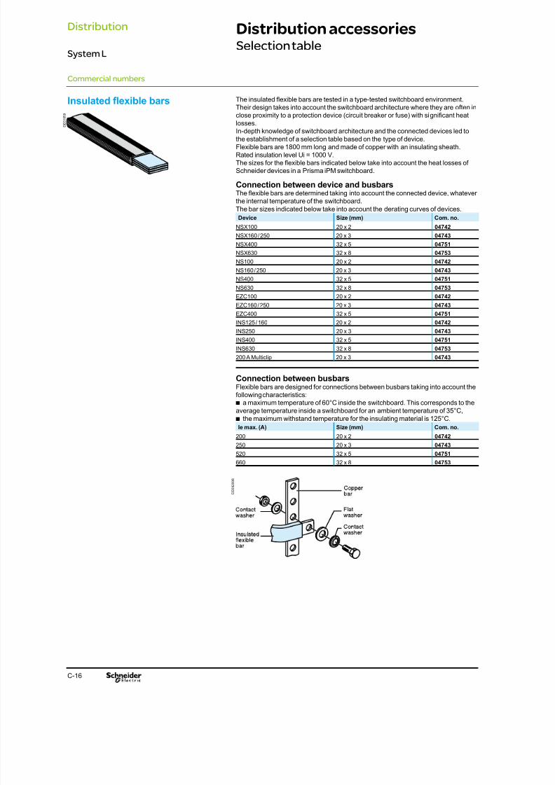
8/15/2019 Prisma iPM System L Catalogue 2011
http://slidepdf.com/reader/full/prisma-ipm-system-l-catalogue-2011 78/128C-16
Distribution accessoriesSelection table
Commercial numbers
The insulated exible bars are tested in a type-tested switchboard environment.
Their design takes into account the switchboard architecture where they are often inclose proximity to a protection device (circuit breaker or fuse) with signicant heat
losses.In-depth knowledge of switchboard architecture and the connected devices led tothe establishment of a selection table based on the type of device.Flexible bars are 1800 mm long and made of copper with an insulating sheath.Rated insulation level Ui = 1000 V.The sizes for the exible bars indicated below take into account the heat losses of
Schneider devices in a Prisma iPM switchboard.
Connection between device and busbarsThe exible bars are determined taking into account the connected device, whatever
the internal temperature of the switchboard.The bar sizes indicated below take into account the derating curves of devices.Device Size (mm) Com. no.
NSX100 20 x 2 04742
NSX160 / 250 20 x 3 04743
NSX400 32 x 5 04751NSX630 32 x 8 04753
NS100 20 x 2 04742
NS160 / 250 20 x 3 04743
NS400 32 x 5 04751
NS630 32 x 8 04753
EZC100 20 x 2 04742
EZC160 / 250 20 x 3 04743
EZC400 32 x 5 04751
INS125 / 160 20 x 2 04742
INS250 20 x 3 04743
INS400 32 x 5 04751
INS630 32 x 8 04753
200 A Multiclip 20 x 3 04743
Connection between busbarsFlexible bars are designed for connections between busbars taking into account thefollowing characteristics:
a maximum temperature of 60°C inside the switchboard. This corresponds to theb
average temperature inside a switchboard for an ambient temperature of 35°C,the maximum withstand temperature for the insulating material is 125°C.b
Ie max. (A) Size (mm) Com. no.
200 20 x 2 04742
250 20 x 3 04743
520 32 x 5 04751
660 32 x 8 04753
Insulated fexible bars
D D 3 1 6 5 9
D D
3 8 2 0 0 8
Distribution
System L
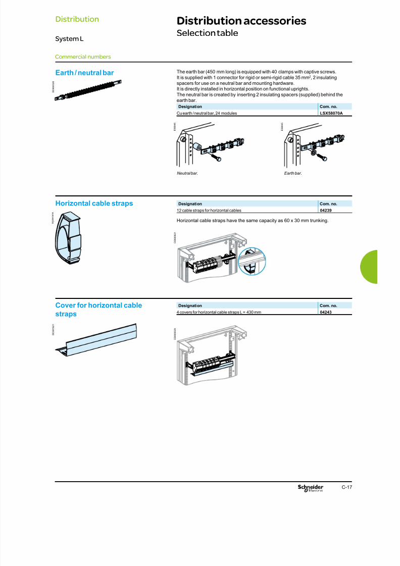
8/15/2019 Prisma iPM System L Catalogue 2011
http://slidepdf.com/reader/full/prisma-ipm-system-l-catalogue-2011 79/128C-17
Distribution accessoriesSelection table
Commercial numbers
The earth bar (450 mm long) is equipped with 40 clamps with captive screws.It is supplied with 1 connector for rigid or semi-rigid cable 35 mm2, 2 insulatingspacers for use on a neutral bar and mounting hardware.
It is directly installed in horizontal position on functional uprights.The neutral bar is created by inserting 2 insulating spacers (supplied) behind theearth bar.Designation Com. no.
Cu earth / neutral bar, 24 modules LSX58070A
Designation Com. no.
12 cable straps for horizontal cables 04239
Earth / neutral bar
Earth bar.Neutral bar.
Cover for horizontal cable
straps
Horizontal cable straps
D D 8
0 0 0 2 0
E 5 6 8 4 5
E 5 6 8 4 6
D D 3 8 1 6 2 1
D D 3 8 1 6 1 8
D D 8 0 0 0 2 1
Horizontal cable straps have the same capacity as 60 x 30 mm trunking.
Designation Com. no.
4 covers for horizontal cable straps L = 430 mm 04243
D D 8 0 0 0 2 9
Distribution
System L

8/15/2019 Prisma iPM System L Catalogue 2011
http://slidepdf.com/reader/full/prisma-ipm-system-l-catalogue-2011 80/128C-18
Distribution accessoriesSelection table
For cable trunking, height = 60 or 80 mm.Designation Com. no.
12 horizontal trunking supports 04255
Horizontal trunking support
D D 3 8 1 6 2 6
D D 8 0 0 0 1 6
Designation Com. no.
Set of 40 M6 x 16 screws (40 screws + 40 contact washers) 04195
Mounting hardware
D D 3 8 1 3 9 8
Commercial numbers
Distribution
System L

8/15/2019 Prisma iPM System L Catalogue 2011
http://slidepdf.com/reader/full/prisma-ipm-system-l-catalogue-2011 81/128C-19
PartitioningSelection table
The partition is a metal barrier installed in a wall mounted enclosure or a 300 mmwide enclosure.It is used to:
separate the functional units from one another,b
create a physical separation between devices and a terminal block, for example.b
It is mounted directly on the functional uprights.Lateral and rear knock-outs are available for cable running or the installation ofbusbars at the rear of the switchboard.Designation Com. no.
Horizontal partition W = 500 mm D = 235 mm LSL58281H
D = 305 mm LSL58282H
Horizontal partition
D D 8 0 0 0 5 1
Vertical partition The metal partition creates a physical separation between the device compartmentand the 300 mm wide duct of a wall mounted enclosure.It is used to:
separate the devices from busbars or a distribution block installed in the duct,b
set up a special zone for terminal blocks in the duct.b
There are knock-outs for cable running.Vertical partitioning It can be cut to length every 150 mm and can be used forpartitioning up to 32-module in wall mounted enclosure (H = 1850 mm).Designation Com. no.
Vertical partition 4 to 24 modules LSL58280V
28 and 32 modules LSL58279V
D D 8 0 0 0 5 2
Commercial numbers
Distribution
System L

8/15/2019 Prisma iPM System L Catalogue 2011
http://slidepdf.com/reader/full/prisma-ipm-system-l-catalogue-2011 82/128D-2
8/15/2019 Prisma iPM System L Catalogue 2011
http://slidepdf.com/reader/full/prisma-ipm-system-l-catalogue-2011 83/128D-1
ContentsEnclosures
System L
Description D-2IP30 / 31/ 40 / 54 in-door enclosures D-2
Commercial numbers D-4IP30 / 40 PAK wall mounted enclosures D-4
IP30 / 31 wall mounted enclosures D-5
IP40 wall mounted enclosures D-6
IP54 wall mounted enclosures D-7
IP30 / 31 / 40 / 54 enclosures accessories D-8
Dimensions D-10

8/15/2019 Prisma iPM System L Catalogue 2011
http://slidepdf.com/reader/full/prisma-ipm-system-l-catalogue-2011 84/128

8/15/2019 Prisma iPM System L Catalogue 2011
http://slidepdf.com/reader/full/prisma-ipm-system-l-catalogue-2011 85/128D-3
Description
Enclosures
System L
IP30 / 31/ 40 / 54 in-door enclosuresGeneral information
1 The enclosureEnclosure size is determined simply according to the switchgear installed, the
connection method and positioning and the required free rows.The enclosures can be ush mounted or surface mounted.
Pre punch-outs at the wall mounted enclosure back are provided for rear cable
insertion.
Square holes every 50 mm make it easy to count modules.
The 600 mm wide wall mounted enclosures are dedicated for functional unit area.
The 300 mm wide duct is dedicated to the cables and busbar area.
The panelling is assembled after mounting devices and cabling to maintain complete
accessibility in the switchboard during its implementation.
2 Removable chassisIt enables to install the empty enclosure on site; then to assemble and cable the
devices on the removable frame at the workshop and to mount it in the PaK
enclosure at the worksite.
3 Front frame
The front frame is supplied with the full kit enclosures. It enables the mounting of thefront plates.
It can be removed for fast, direct access to all the devices, with all the front plates
mounted on.
4 DoorsBoth plain and transparent doors are reversible and designed for quick and easy left
or right-hand mounting by a single person.
A handle is only available on the 600 mm wide doors. The 300 mm wide duct is
dedicated to the professional staff. For greater safety, it is closed with screws.
A range of locks are available for the “push and pull” handle.
The wall mounted enclosures must have the same depth to be combined each other
horizontally and vertically.
The 28-module and 32-module height enclosures can be horizontally combined only.
An assemby kit is supplied with the 300 mm wide duct.For other combinations than 600 + 300 mm wide enclosures, assembly kits are
available in option.
The degrees of protection are maintained.
Side-by-side combinationIt ensures the mechanical connection between the wall mounted enclosures and the
duct.
Vertical combination A combination kit ensures the mechanical connection between the two functional
unit wall mounted enclosures.
“L” shape combinationThe “L” shape is created by combining two enclosures (extension or duct) with a
600 mm wide enclosure.
Square combinationThe square shape is created by combining three enclosures (extension or duct) with
a basic enclosure.
Square combinations are only possible with enclosures that have the same number
of vertical modules.
Enclosure description
Enclosure combination
IP30 / 31 / 40 wall mounted enclosuresFrom 4 to 24 modules, switchboards is mounted on a wall through the holes at theb
rear of the switchboard. It is possible to mount the switchboards on a wall by using
external wall mounted xing rings (2 x LSL58274A).
From 28 to 32 modules, switchboards is mounted on a wall by using external wallb
mounted xing rings (LSL58274A).
IP54 wall mounted enclosuresSwitchboards is mounted on a wall by using external wall mounted xing ringsb
(supplied).
Enclosure xing
D D 8 0 0 0 3 2
D D
8 0 0 0 5 4
D D 8 0 0 4 7 3

8/15/2019 Prisma iPM System L Catalogue 2011
http://slidepdf.com/reader/full/prisma-ipm-system-l-catalogue-2011 86/128
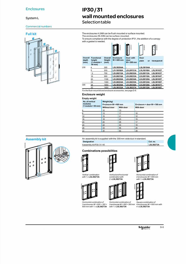
8/15/2019 Prisma iPM System L Catalogue 2011
http://slidepdf.com/reader/full/prisma-ipm-system-l-catalogue-2011 87/128D-5
Commercial numbers
The enclosures 4-24M can be ush mounted or surface mounted.
The enclosures 28-32M can be surface mounted.
To ensure compliance with the degree of protection IP31, the addition of a canopy
with a gasket is needed.
Overalldepth(mm)
Functionalheight(1 module =50 mm)
OverallHeight(mm)
EnclosureW = 600 mm
Duct withdoorW = 300 mm
Door
plain or transparent
235 4 300 LSL58204A - LSL58104A -
8 500 LSL58208A LSL58231A LSL58108A LSL58162T
12 700 LSL58212A LSL58232A LSL58112A LSL58163T
16 900 LSL58216A LSL58233A LSL58116A LSL58164T
20 1100 LSL58220A LSL58234A LSL58120A LSL58165T
24 1300 LSL58224A LSL58235A LSL58124A LSL58166T305 28 1650 LSL58328A LSL58336A LSL58128A LSL58167T
32 1850 LSL58332A LSL58337A LSL58132A LSL58168T
For the ush-mount kit and enclosure accessories, see page D-8.
Enclosure weight
Empty weight
No. of verticalmodules(1 module = 50 mm)
Weight (kg)
Enclosure W = 600 mm Enclosure + door W = 300 mm
Without door With door With door
4 10 13 -
8 13 17 10
12 15 21 12
16 18 25 15
20 20 29 17
24 22 33 19
28 33 46 26
32 35 50 28
Full kit
D D 8 0 0 4 7 8
D D 3 8 0 6 2 3
D D 3 8 0 6 2 4
D D 8 0 0 0 5 7
An assembly kit is supplied with the 300 mm wide duct in standard.
Designation Cat. no.
4 assembly kit IP30 / 31 / 40 LSL58273A
Combinations possibilities
Vertical combinationwith 1 x LSL58273A
Vertical and horizontalcombination with2 xLSL58273A
Horizontal combination of2 enclosures W = 600 mm with 1 x LSL58273A
Horizontal combination of3 enclosures W = 600 + 300 +
600 mm with 1 x LSL58273A
Horizontal combination of2 enclosures W = 600 + 300 mm
with 1 x LSL58273A
Square combination of4 enclosures W = 600 mm with
4 xLSL58273A
Assembly kit
D D 8 0 0 0 8 8
D D 8 0 0 0 6 4
D D 8 0 0 0 6 2
D D 8 0 0 0 6 1
D D 8 0 0 0 6 0
D D 8 0 0 0 5 8
Enclosures
System L
IP30 / 31
wall mounted enclosuresSelection table
D D 8
0 0 0 5 4

8/15/2019 Prisma iPM System L Catalogue 2011
http://slidepdf.com/reader/full/prisma-ipm-system-l-catalogue-2011 88/128D-6
Commercial numbers
Overalldepth(mm)
Functional height(1 module= 50 mm)
OverallHeight(mm)
EnclosureW = 600 mm
Duct withdoorW = 300 mm
Door Gasket kit
and
accessoriesplain or transparent
235 4 300 LSL58204A - LSL58104A - LSL58276A
8 500 LSL58208A LSL58231A LSL58149A LSL58162T LSL58276A
12 700 LSL58212A LSL58232A LSL58150A LSL58163T LSL58276A
16 900 LSL58216A LSL58233A LSL58151A LSL58157T LSL58276A
20 1100 LSL58220A LSL58234A LSL58152A LSL58158T LSL58276A
24 1300 LSL58224A LSL58235A LSL58153A LSL58159T LSL58276A
305 28 1650 LSL58328A LSL58336A LSL58154A LSL58167T LSL58276A
32 1850 LSL58332A LSL58337A LSL58155A LSL58168T LSL58276A
Enclosure accessories, see page D-8.
Enclosure weight
Empty weight
No. of verticalmodules(1 module = 50 mm)
Weight (kg)
Enclosure W = 600 mm Enclosure + door W = 300 mm
Without door With door With door
4 10 13 -
8 13 17 10
12 15 21 12
16 18 25 15
20 20 29 17
24 22 33 19
28 33 46 26
32 35 50 28
Full kit D D 8 0 0 4 7 8
D D 3 8 0 6 2 4
D D 8 0 0 3 1 1
D D 8 0 0 0 5 7
An assembly kit is supplied with the 300 mm wide duct in standard.
Designation Cat. no.
4 assembly kit IP30 / 31 / 40 LSL58273A
Combinations possibilities
Vertical combinationwith 1 x LSL58273A
Vertical and horizontalcombination with2 xLSL58273A
Horizontal combination of2 enclosures W = 600 mm with 1 x LSL58273A
Horizontal combination of3 enclosures W = 600 + 300 +600 mm with 1 x LSL58273A
Horizontal combination of2 enclosures W = 600 + 300mm with 1 x LSL58273A
Square combination of4 enclosures W = 600 mm with4 xLSL58273A
Assembly kit
D D 8 0 0 0 8 8
D D 8 0 0 0 6 4
D D 8 0 0 0 6 3
D D 8 0 0 0 6 2
D D 8 0 0 0 6 1
D D 8 0 0 0 6 0
D D 8 0 0 0 5 8
Enclosures
System L
IP40
wall mounted enclosuresSelection table
D D 8
0 0 0 5 4
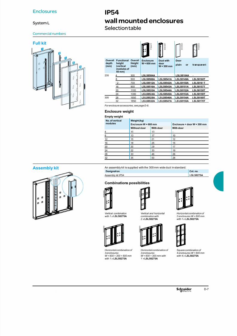
8/15/2019 Prisma iPM System L Catalogue 2011
http://slidepdf.com/reader/full/prisma-ipm-system-l-catalogue-2011 89/128D-7
Commercial numbers
Enclosures
System L
IP54
wall mounted enclosuresSelection table
D D 8
0 0 0 5 4
Overalldepth(mm)
Functionalheight(verticalmodules of50 mm)
OverallHeight(mm)
EnclosureW = 600 mm
Duct withdoorW = 300 mm
Door
plain or transparent
235 4 300 LSL58504A - LSL58104A -
8 500 LSL58508A LSL58541A LSL58149A LSL58160T
12 700 LSL58512A LSL58542A LSL58150A LSL58161T
16 900 LSL58516A LSL58543A LSL58151A LSL58157T
20 1100 LSL58520A LSL58544A LSL58152A LSL58158T
24 1300 LSL58524A LSL58545A LSL58153A LSL58159T
305 28 1650 LSL58528A LSL58546A LSL58154A LSL58169T
32 1850 LSL58532A LSL58547A LSL58155A LSL58170T
For enclosure accessories, see page D-8.
Enclosure weight
Empty weight
No. of verticalmodules
Weight (kg)
Enclosure W = 600 mm Enclosure + door W = 300 mm
Without door With door With door
4 10 13 -
8 13 17 10
12 15 21 12
16 18 25 15
20 20 29 17
24 22 33 19
28 33 46 26
32 35 50 28
Full kit
D D 8 0 0 4 7 8
D D 8 0 0 0 5 7
D D 3 8 0 6 2 3
D D 3 8 0 6 2 4
An assembly kit is supplied with the 300 mm wide duct in standard.
Designation Cat. no.
Assembly kit IP54 LSL58275A
Combinations possibilities
Vertical combinationwith 1 x LSL58275A
Vertical and horizontalcombination with2 x LSL58275A
Horizontal combination of2 enclosures W = 600 mm with 1 x LSL58275A
Horizontal combination of3 enclosuresW = 600 + 300 + 600 mmwith 1 x LSL58275A
Horizontal combination of2 enclosuresW = 600 + 300 mm with1 x LSL58275A
Square combination of4 enclosures W = 600 mmwith 4 x LSL58275A
Assembly kit
D D 8 0 0 0 8 9
D D 8 0 0 0 9 2
D D 8 0 0 0 9 1
D D 8 0 0 0 9 0
D D 8 0 0 0 9 3
D D 8 0 0 0 9 4
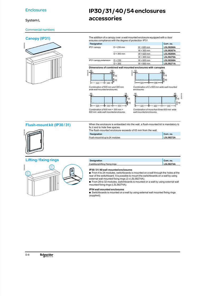
8/15/2019 Prisma iPM System L Catalogue 2011
http://slidepdf.com/reader/full/prisma-ipm-system-l-catalogue-2011 90/128
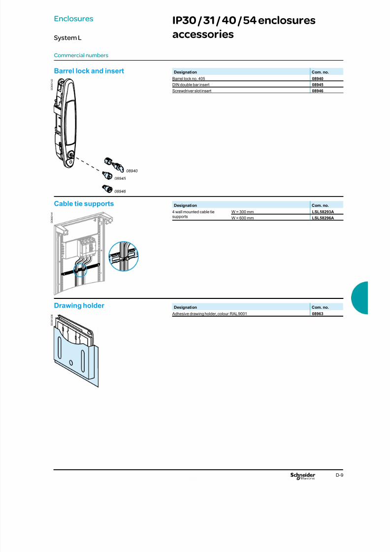
8/15/2019 Prisma iPM System L Catalogue 2011
http://slidepdf.com/reader/full/prisma-ipm-system-l-catalogue-2011 91/128D-9
Commercial numbers
IP30 / 31 / 40 / 54 enclosures
accessories
Designation Com. no.
Barrel lock no. 405 08940
DIN double bar insert 08945Screwdriver slot insert 08946
Barrel lock and insert
Designation Com. no.
4 wall mounted cable tiesupports
W = 300 mm LSL58293A
W = 600 mm LSL58296A
Cable tie supports
Designation Com. no.
Adhesive drawing holder, colour RAL 9001 08963
Drawing holder
08940 08945
08946
D D 3 8 1 2 0 8
D D 8
0 0 1 2 2
D D 8 0 0 1 4 1
Enclosures
System L

8/15/2019 Prisma iPM System L Catalogue 2011
http://slidepdf.com/reader/full/prisma-ipm-system-l-catalogue-2011 92/128D-10
Dimensions
Enclosures
System L
IP30 / 40 PAK
wall mounted enclosures
49
93
LSL58802A LSL58824A and LSL58825A LSL58826A and LSL58827A
Wall mounted enclosures Door
Wall mounting
Depth behind front plateFunctional uprights Adjustable device rail Slotted mounting plates Plain mounting plate
No of modules
12 16 20 24
H 700 900 1100 1300
Aperture
Top cable entry
No of modules
12 16 20 24
A 800 1000 1200 1400
A’ 620 820 1020 1220
D D 8
0 0 0 9 5
D D 8 0 0 4 7 6
D D 8
0 0 4 7 9
D D 8 0 0 4 7 7
D D 8 0 0 0 7 7
D D 8 0 0 1 0 9
D D 8 0 0 1 1 5
D D 8 0 0 1 1 6
D D 8 0 0 1 1 7
D D 8 0 0 5 3 8
D D 8 0 0 4 1 0
D D 8 0 0 5 4 7
320
527
105
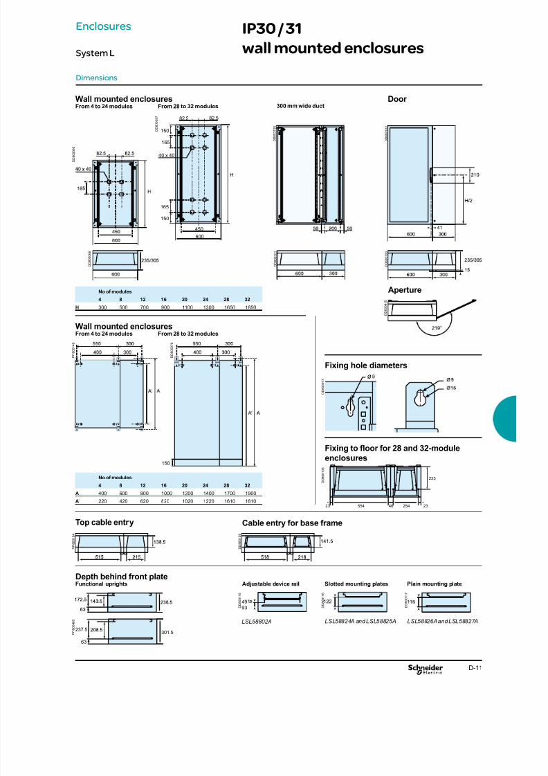
8/15/2019 Prisma iPM System L Catalogue 2011
http://slidepdf.com/reader/full/prisma-ipm-system-l-catalogue-2011 93/128D-11
Dimensions
49
93
82.5 82.5
150
150
165
165
40 x 40
450
600
H
237.5
63
301.5
LSL58802A LSL58824A and LSL58825A LSL58826A and LSL58827A
Wall mounted enclosuresFrom 4 to 24 modules From 28 to 32 modules
Top cable entry
Depth behind front plateFunctional uprights
Fixing to oor for 28 and 32-module
enclosures
300 mm wide ductDoor
Cable entry for base frame
Adjustable device rail Slotted mounting plates Plain mounting plate
No of modules
4 8 12 16 20 24 28 32
H 300 500 700 900 1100 1300 1650 1850
Aperture
No of modules
4 8 12 16 20 24 28 32
A 400 600 800 1000 1200 1400 1700 1900
A’ 220 420 620 820 1020 1220 1610 1810
Wall mounted enclosuresFrom 4 to 24 modules From 28 to 32 modules
Fixing hole diameters
D D 8 0 0 0 9 5
D D 8 0 0 0 6 6
D D 8 0 0 0
9 7
D D 8 0 0 1 0 0
D D 8 0 0 1 0 1
D D 8 0 0 1 0 2
D D 8 0 0 1 0 3
D D 8 0 0 1 0 4
D D 8 0 0 1 0 5
D D 8 0 0 1 1 5
D D 8 0 0 1 1 6
D D 8 0 0 1 1 7
D D 8 0 0 4 8 0
D D 8 0 0 4 1 0
D D 8 0 0 1 4 9
D D 8 0 0 0 7 6
D D 8 0 0 1 0 8
23 2346554 254
225
D D 8 0 0 0 7 7
Enclosures
System L
IP30 / 31
wall mounted enclosures
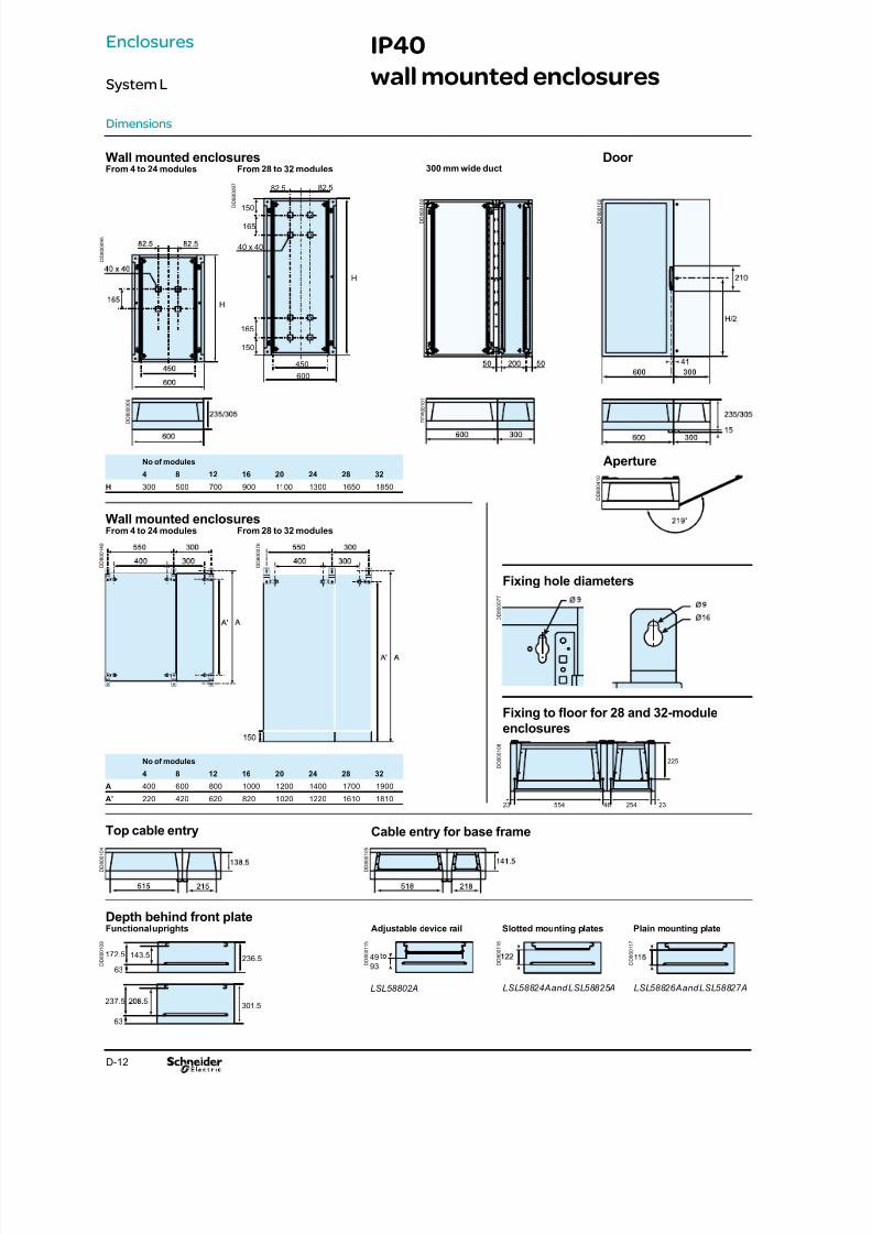
8/15/2019 Prisma iPM System L Catalogue 2011
http://slidepdf.com/reader/full/prisma-ipm-system-l-catalogue-2011 94/128D-12
Dimensions
172.5
63
143.5236.5 49
93
82.5 82.5
150
150
165
165
40 x 40
450
600
H
237.5
63
301.5
D D 8 0 0 0 6 6
LSL58802A LSL58824A and LSL58825A LSL58826A and LSL58827A
Wall mounted enclosuresFrom 4 to 24 modules From 28 to 32 modules
Top cable entry
Depth behind front plateFunctional uprights
Fixing to oor for 28 and 32-module
enclosures
300 mm wide ductDoor
Cable entry for base frame
Adjustable device rail Slotted mounting plates Plain mounting plate
No of modules
4 8 12 16 20 24 28 32
H 300 500 700 900 1100 1300 1650 1850
Aperture
No of modules
4 8 12 16 20 24 28 32
A 400 600 800 1000 1200 1400 1700 1900
A’ 220 420 620 820 1020 1220 1610 1810
Wall mounted enclosuresFrom 4 to 24 modules From 28 to 32 modules
Fixing hole diameters
D D 8 0 0 0 9 7
D D 8 0 0 1 0 0
D D 8 0 0 1 0 1
D D 8 0 0 1 0 2
D D 8 0 0 1 0 4
D D 8 0 0 1 0 5
D D 8 0 0 0 7 7
D D 8 0 0 1 0 9
D
D 8 0 0 1 1 5
D
D 8 0 0 1 1 6
D
D 8 0 0 1 1 7
D D 8 0 0 4 1 0
D D 8 0 0 1 4 9
D D 8 0 0 0 7 6
D D 8 0 0 0 9 5
D D 8 0 0 1 0 8
23 2346554 254
225
Enclosures
System L
IP40
wall mounted enclosures

8/15/2019 Prisma iPM System L Catalogue 2011
http://slidepdf.com/reader/full/prisma-ipm-system-l-catalogue-2011 95/128

8/15/2019 Prisma iPM System L Catalogue 2011
http://slidepdf.com/reader/full/prisma-ipm-system-l-catalogue-2011 96/128E-2

8/15/2019 Prisma iPM System L Catalogue 2011
http://slidepdf.com/reader/full/prisma-ipm-system-l-catalogue-2011 97/128E-1
Contents
Spare parts E-2
Electrical characteristics E-3Designing Prisma iPM power circuits E-3
Designing connections y 630 A E-4
Designing connections with cables E-6
Designing the PEN conductor E-7
Mechanical characteristics E-8Degree of protection E-8
Properties of metal enclosure E-10
Environment E-12Environmental prole of Prisma iPM switchboards E-12
Characteristics
System L

8/15/2019 Prisma iPM System L Catalogue 2011
http://slidepdf.com/reader/full/prisma-ipm-system-l-catalogue-2011 98/128E-2
Spare parts
Spare parts
Wall mounted enclosure Com. no.
Door spare parts for system L LSL58033A
20 front plate screws + nuts LSX58030A
Prisma iPM spare parts handle LSX58031A
Door accessories
Characteristics
System L
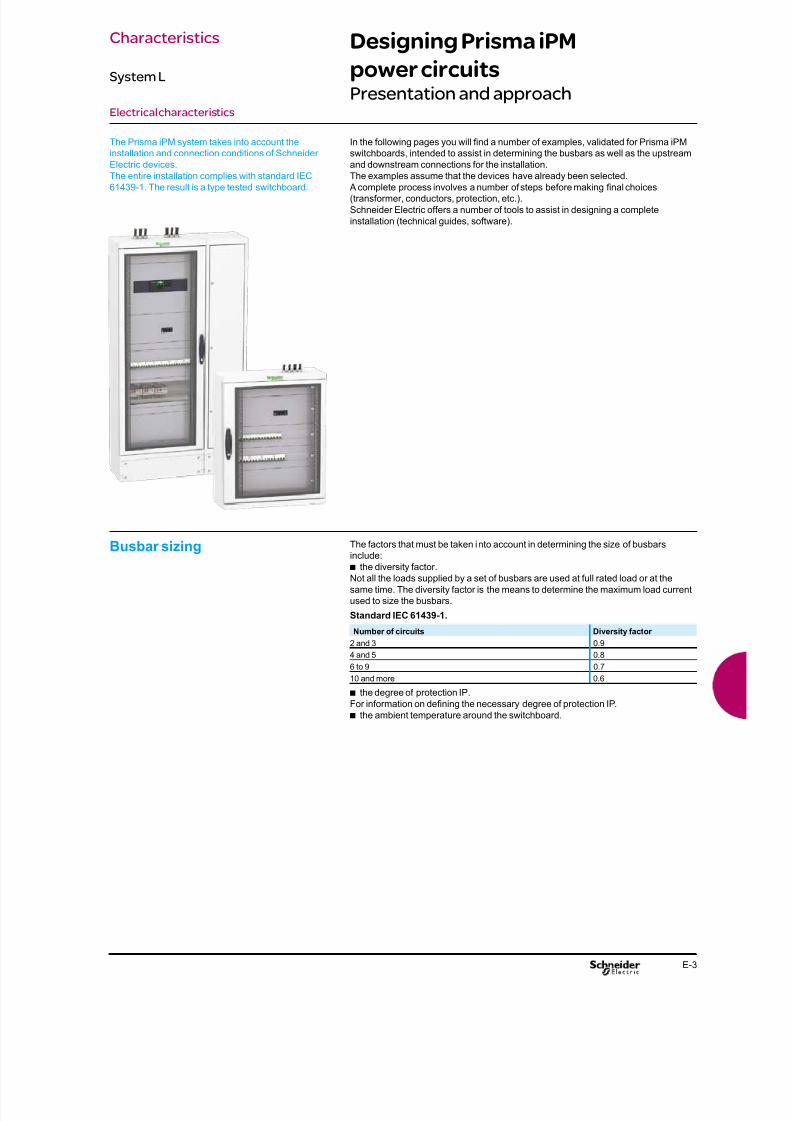
8/15/2019 Prisma iPM System L Catalogue 2011
http://slidepdf.com/reader/full/prisma-ipm-system-l-catalogue-2011 99/128E-3
Designing Prisma iPM
power circuitsPresentation and approach
Electrical characteristics
The Prisma iPM system takes into account the
installation and connection conditions of Schneider
Electric devices.
The entire installation complies with standard IEC61439-1. The result is a type tested switchboard.
In the following pages you will nd a number of examples, validated for Prisma iPM
switchboards, intended to assist in determining the busbars as well as the upstream
and downstream connections for the installation.
The examples assume that the devices have already been selected. A complete process involves a number of steps before making nal choices
(transformer, conductors, protection, etc.).
Schneider Electric offers a number of tools to assist in designing a complete
installation (technical guides, software).
Busbar sizing The factors that must be taken into account in determining the size of busbars
include:
the diversity factor.b
Not all the loads supplied by a set of busbars are used at full rated load or at the
same time. The diversity factor is the means to determine the maximum load current
used to size the busbars.
Standard IEC 61439-1.
Number of circuits Diversity factor
2 and 3 0.9
4 and 5 0.8
6 to 9 0.7
10 and more 0.6
the degree of protection IP.b
For information on dening the necessary degree of protection IP.
the ambient temperature around the switchboard.b
Characteristics
System L
8/15/2019 Prisma iPM System L Catalogue 2011
http://slidepdf.com/reader/full/prisma-ipm-system-l-catalogue-2011 100/128E-4
Designing connections y 630 ADevice connections
Electrical characteristics
Insulated exible copper bars Switchboards that comply with standard IEC 61439-1It is imperative to use the values indicated below that have been validated for the
installation of devices in Prisma iPM switchboards.
The parameters determining the size of exible bars are:
the environment in which the devices are installed:b
v position in the enclosure,
v dimensions of other conductors in the circuit,
v ambient temperature around the switchboard,
the characteristics of the connected devices:b
v device heat losses,
v the type of installation (horizontal or vertical),
v the type of device (xed or withdrawable).
Only the equipment manufacturer with in-depth knowledge on:
the characteristics of the installed devicesb
the conguration of the installation in the enclosure can provide the correct sizes of
exible bars for a given permissible current. Insulated, exible bars make for easy,
fast and exible implementation up to 630 A, but higher ratings require sizes that
cancel these advantages.For high Isc values, it is advised to use rigid bars which require fewer supports.
Insulated exible bars are better than cables, they offer:exible copper bars with an insulating sheath,b
better insulation temperature withstand (125°C for bars, 105°C for cables) and ab
larger exchange surface for an equivalent size, i.e. a smaller size for a given current,
greater rigidity offering better electrodynamic characteristics for short-circuitb
currents,
no intermediate parts (lugs) for a direct connection between the device and theb
busbars therefore less temperature rise and less risk of error,
fast implementation of prefabricated connections already cut to length, formed andb
drilled.
Technical characteristics
thickness of the insulation: variable depending on the bar size, 2 mm on average,b
rated insulation level Ui = 1000 V,b
impulse withstand voltage Uimp = 12 kV,b
maximum withstand temperature of insulating material = 125°C.b
Connection
Note: The values indicated above have been validated for Prisma iPM switchboards.
In all cubicles with IP y 54
the switchboard internal temperature is 60°C,b
the withstand temperature of the insulating material is 125°C.b
If the withstand temperature of the insulation is only 105°C, use the next largest
exible bar.
The bar sizes indicated below take into account the derating curves of devices.
Connection of devices and distribution blocks to busbars
Device INS125 (1) INS160 (1) INS250 (1) INS320 (1)
INS400 (1)
INS500 (1)
INS630 (1)
NS100(1) NS160(1)
S (mm) 20 x 2 20 x 2 20 x 3 32 x 5 32 x 8 20 x 2 20 x 3
DeviceNS250(1) NS400(1) NS630 (1) NSX100 (1) NSX160 (1) NSX250 (1) NSX400 (1)
S (mm) 20 x 3 32 x 5 32 x 8 20 x 2 20 x 3 20 x 3 32 x 5
Device NSX630 (1) EZC100 (1) EZC160 (1) EZC250 (1) EZC400 (1)
S (mm) 32 x 8 20 x 2 20 x 3 20 x 3 32 x 5
(1) The values for circuit breakers apply to contactors with the same ratings.
Device Multiclip distributionblock (200 A)
S (mm) 20 x 3
Disconnectors, terminal blocks, connections, busbars to
busbars
I max. (60 °C) 200 A 250 A 400 A 400 A 480 A 520 A 660 A
S (mm) 20 x 2 20 x 3 24 x 5 24 x 5 24 x 6 32 x 5 32 x 8
Characteristics
System L

8/15/2019 Prisma iPM System L Catalogue 2011
http://slidepdf.com/reader/full/prisma-ipm-system-l-catalogue-2011 101/128E-5
Electrical characteristics
Designing connections y 630 ACompact circuit breakers
NSX100 to NSX630
Compact NSX100 to NSX250
Insulated exible copper bars
Devices Permissible current (A)
Ambient temperature around the switchboard25 °C 30 °C 35 °C 40 °C 45 °C 50 °C
IP y 54
NSX100TMD-TMG
Size per phase 20 x 2 20 x 2 20 x 2 20 x 2 20 x 2 20 x 2
I (A) 100 97.5 95 92.5 90 85
NSX125TMD-TMG
Size per phase 20 x 2 20 x 2 20 x 2 20 x 2 20 x 2 20 x 2
I (A) 125 122 119 116 113 100
NSX160 (1)
TMD-TMGSize per phase 20 x 3 20 x 3 20 x 3 20 x 3 20 x 3 20 x 3
I (A) 160 156 152 147 144 140
NSX250 (1)
TMD-TMGSize per phase 20 x 3 20 x 3 20 x 3 20 x 3 20 x 3 20 x 3
I (A) 250 244 238 231 225 198
NSX100STR
Size per phase 20 x 2 20 x 2 20 x 2 20 x 2 20 x 2 20 x 2
I (A) 100 100 100 100 100 100
NSX160STR
Size per phase 20 x 3 20 x 3 20 x 3 20 x 3 20 x 3 20 x 3I (A) 160 160 160 160 160 160
NSX250 (2)
STRSize per phase 20 x 3 20 x 3 20 x 3 20 x 3 20 x 3 20 x 3
I (A) 250 250 237.5 237.5 225 225
(1) For a withdrawable NSX160 or NS250 equipped with a Vigi or an insulation-monitoringmodule, multiply the In values by 0.9.(2) For a withdrawable NSX250 equipped with a Vigi or an insulation-monitoring module, multiplythe In values by 0.86.
Compact NSX400 to NSX630
Insulated exible copper bars
Devices Permissible current (A)
Ambient temperature around the switchboard25 °C 30 °C 35 °C 40 °C 45 °C 50 °C
IP y 54
NSX400N/H/Lxed
Size per phase 32 x 5 32 x 5 32 x 5 32 x 5 32 x 5 32 x 5
I (A) 400 400 400 390 380 370
NSX400N/H/Lwith Vigi
Size per phase 32 x 5 32 x 5 32 x 5 32 x 5 32 x 5 32 x 5
I (A) 400 390 380 370 360 350
NSX630N/H/Lxed
Size per phase 32 x 8 32 x 8 32 x 8 32 x 8 32 x 8 32 x 8
I (A) 630 615 600 585 570 550
NSX630N/H/Lwith Vigi
Size per phase 32 x 8 32 x 8 32 x 8 32 x 8 32 x 8 32 x 8
I (A) 570 550 535 520 505 490
Characteristics
System L
8/15/2019 Prisma iPM System L Catalogue 2011
http://slidepdf.com/reader/full/prisma-ipm-system-l-catalogue-2011 102/128E-6
Designing connections with
cables
Electrical characteristics
Cables Practical guidelinesSchneider Electric provides cabling recommendations according to the rating of the
circuit breaker.
The size of cables must be selected according to:the level of current,b
the ambient temperature around the conductors,b
the degree of protection for the switchboard.b
The tables below take into account the installation conditions for each type of device
(permissible temperature at connection terminals, etc.).
They follow the temperature derating values for installed devices in all cubicles with
cover panels rated IP y 55.
switchboard internal temperature 60°C,b
connections using copper cables.b
For wall mounted enclosures, the volumes, ratings and connection lengths are low.
Select the values in the “Cables tied together” column, according to the IP.
Connection of circuit breakers Size of
cables
(mm²)
Permissible current (A)
Cables tied individually Cable tied together
IP y 31 IP > 31 IP y 31 IP > 31
1.5 16 14 14 12
2.5 25 25 22 20
4 32 29 28 24
6 40 39 36 33
10 63 55 55 50
16 90 77 80 70
25 110 100 100 93
35 135 125 125 120
50 180 15070 230 190
95 275 230
Note: Schneider Electric recommends connecting NSX400 / 630 circuit breakers with insulatedexible bars or rigid bars.
Size of
cables
(mm²)
Permissible current (A)
Cables tied individually Cable tied together
IP y 31 IP > 31 IP y 31 IP > 31
1.5 13 12 12 10
2.5 23 21 20 19
4 28 26 25 22
6 36 35 32 30
10 55 50 50 46
16 80 70 72 63
25 100 90 90 84
35 120 115 110 103
50 165 135
70 210 176
95 250 210
Connection of other devices
Supply of devicesfor outgoers y 630 A
Flexible copper bars with an insulating cover.
To determine the required sizes for exible bars, see the tables starting on, whichindicate the correct size for each type of connected device.
an insulated exible bar (not connected) must meet standards IEC 60243-1b
(dielectric) and IEC 60332-1 (re),
a exible bar connected to a device in an enclosure must comply with standardb
IEC 61439-1 (see explanations on).
Cables
To determine the cables required, see the table on.
They can be used to determine:
the size of cables as a function of:b
v the circuit breaker rating,
v the current,
v the ambient temperature around the switchboard,
the permissible current for individually tied cables or touching cables as a functionb
of:
v the size of the cables,v the degree of protection for the switchboard.
Characteristics
System L
8/15/2019 Prisma iPM System L Catalogue 2011
http://slidepdf.com/reader/full/prisma-ipm-system-l-catalogue-2011 103/128E-7
Designing the PEN conductorPower circuit
Electrical characteristics
Size of PEN protective conductor Practical guidelinesThe size of the PEN is determined in the same manner as a neutral conductor, i.e.:
for copper single-phase circuits or sizedb y 16mm², it must be the same size as the
phase conductorsfor copper three-phase circuits sized > 16 mm², it can be:b
v the same size as the phase conductors,
v smaller on the condition that:
- the current likely to ow in the neutral during normal operation is less than the
permissible current for the conductor,
- the power rating of single-phase loads does not exceed 10% of the total rating.
The conductor must be accessible to enable connections both in the factory and on
site, as well as checks on the tightness of connections.
Implementing the PEN protectiveconductor
Practical guidelines According to standard IEC 61439-1, the practical guidelines for implementing the
PEN are the following:
at the entry to the assembly, the PEN connection must be next to the phaseb
connections,within the assembly, the PEN does not need to be insulated from the exposedb
conductive parts (except on sites where there is a risk of re or explosion),
the size of the conductor must be at least equal to that of the neutral,b
the size must remain constant throughout the main busbars,b
the change from a TNC to a TNS system must take place at a single point in theb
switchboard, via a marked neutral-disconnection bar that is accessible and can be
dismantled to facilitate the impedance measurement of the fault loop,
after the TNS creation point, it is forbidden to recreate a TNC system.b
The PE and the neutral must meet their specic requirements.
Characteristics
System L

8/15/2019 Prisma iPM System L Catalogue 2011
http://slidepdf.com/reader/full/prisma-ipm-system-l-catalogue-2011 104/128E-8
Degree of protectionGeneral
Mechanical characteristics
Standard IEC 60364-5-51 listed and codied a large number of external
inuences to which electrical installations can be subjected, including the
presence of water, solid objects, shocks, vibrations, corrosive substances,
etc.
Degree of protection IP Standard IEC 60529 (IP code, February 2001) indicates the degrees of protection
provided by an enclosure for electrical devices against access to hazardous parts,
against penetration of solid foreign objects and against penetration of water.
These standards do not apply for the protection against the risks of explosion or
conditions such a humidity, corrosive vapour, fungus or vermin.
The IP code is made up of two characteristic numerals and can include an additional
letter when the actual protection for persons against access to the hazardous parts
is better than that indicated by the rst numeral.
The rst numeral characterises the protection provided against the ingress of solid
foreign objects and the protection of persons.
The second numeral characterises the protection provided against the ingress of
water with harmful effects.
1st numeral 2nd numeral
Protection of persons Protection against ingress of solid objects Protection against ingress of water
1 Protected againstaccess with back ofhand
Protected againstsolid foreign objects larger than 50 mm
1 Protected againstvertically falling waterdrops (condensation)
2 Protected againstaccess with a nger
Protected againstsolid foreign objectslarger than 12.5 mm
2 Protected againstvertically falling waterdrops when enclosuretilted up to 15°
3 Protected againstaccess with a tool
Protected againstsolid foreign objectslarger than 2.5 mm
3 Protected againstspraying water up to60° from vertical
4 Protected againstaccess with a wire
Protected againstsolid foreign objectslarger than 1 mm
4 Protected againstsplashing water fromall directions
5 Protected againstaccess with a wire
Protected against dust(dust protected)
5 Protected againstwater jets from alldirections
6 Protected againstaccess with a wire
Dust tight 6 Protected againstpowerful water jetsfrom all directions
7 Protected against theeffects of temporaryimmersion in water
8 Protected against theeffects of continuousimmersion in water
D D 3 8 1 9 5 9
D D 3 8 1 9 6 2
D D 3 8 1 9 6 1
D D 3 8 1 9 6 2
D D 3 8 1 9 6 2
D D 3 8 1 9 6 0
D D 3 8 1 9 6 4
D D 3 8 1 9 6 3
D D 3 8 1 9 6 1
D D 3 8 1 9 6 2
D D 3 8 1 9 5 9
D D 3 8 1 9 6 5
D D 3 8 1 9 7 0
D D 3 8 1 9 6 7
D D 3 8 1 9 6 8
D D 3 8 1 9 6 9
D D 3 8 1 9 6 6
D D 3 8 1 9 7 1
D D 3 8 1 9 7 2
D D 3 8 1 9 7
3
Characteristics
System L

8/15/2019 Prisma iPM System L Catalogue 2011
http://slidepdf.com/reader/full/prisma-ipm-system-l-catalogue-2011 105/128E-9
Degree of protectionGeneral
Mechanical characteristics
Additional letter (optional) Protection of persons against access to hazardous parts.
Designation Protection
A Protected against access with back of handB Protected against access with a nger
C Protected against access with a tool
D Protected against access with a wire
The additional letter is used only if the actual protection of persons is higher than that
indicated by the rst characteristic numeral of the IP code.
If only the protection of persons is of interest, the two characteristic numerals are
replaced by “X”, e.g. IPxxB.
Example
Protected against solid foreign objectslarger than 2.5 mm
No protection
Protected against access witha tool 1 mm in diameter
IP30D
Remarks on the degree of
protection IP
the degree of protection IP must always be read and understood numeral byb
numeral and not as a whole.
For example, an IP31 wall mounted enclosure is suitable for an environment that
requires a minimum degree of protection IP21. But an IP30 wall mounted enclosure
is not suitable.
the degrees of protection indicated in this catalogue are valid for the enclosures asb
presented. However, the indicated degree of protection is guaranteed only when the
installation and device mounting are carried out in accordance with professional
standards.
Degree of protection against
mechanical impacts IK
Standard IEC 62262 denes an IK code characterising the capacity of products to
resist mechanical impacts from all sides.
IK code Impact energy (joules(1))
01 0.14
02 0.2
03 0.35
04 0.5
05 0.7
06 1
07 2
08 5
09 10
10 20
(1)The SI derived unit used to measure energy or work. One joule is equal to the energy used toaccelerate a body with a mass of one kilogram using one newton of force over a distance of onemeter. One joule is also equivalent to one watt-second.
RecommendationIn terms of the risks of impacts, selection of the IK code can be summed up as
indicated below.
Site Recommended IK
No risk of major impact Technical rooms 07
Signicant risk of impact thatcan damage devices
Hallways 08 (switchboard with door)
Maximum risk of impact that candamage the switchboard
Workshops 10
Characteristics
System L

8/15/2019 Prisma iPM System L Catalogue 2011
http://slidepdf.com/reader/full/prisma-ipm-system-l-catalogue-2011 106/128E-10
Properties of metal enclosure
Mechanical characteristics
Schneider Electric enclosures comply with standard EN 50298 for empty enclosures.
The sheet metal used for Schneider Electric enclosures receives a thermosetting,
polyester-resin-modied epoxy powder for colour and appearance.
This coat system provides excellent nish and corrosion protection.
Mechanical properties of powdercoated surfaces
Test conditions
Adhesion (cross-hatch and pull-off) class 0 required (ISO 2409)
Impact strength (1) > 1 kg / 40 cm (ISO 6272)
Mandrel bending test (2) < 10 mm (ISO 6860)
Persoz hardness 300 s (ISO 1522)
(1) No cracking of the paint lm after dropping a weight of one kilogram on the test piece from aheight of 50 centimetres.(2) Film cracks over a length of 10 millimetres maximum.
Test conditions:
Two tests carried out on the same 1 mm thick steel sheet test piece.
cyclical damp-heat test:b
v as per standard IEC 68-2-30,
- six 24-hour cycles at temperatures higher than 40°C,
continuous resistance to neutral salt mist:b
v the tests were carried out over a period of 400 hours, far more than the 48 hours
required by the standard for indoor installations,
v as per standard IEC 68-2-11 and ISO 7253
- 400 hours without blistering for normal surface on test piece,
- 250 hours for a scratched surface.
Evaluation of corrosion as per ISO 4628:
adhesion: classb y 1,
blistering: degree 1 dim.1,b
rusting: Ri 1,b
cracking: class 1,b
aking imp. 1 dim. 1.b
propagation of corrosion under scratch with respect to the scratch axis: 3 mm
max.
Articial ageing test on powdercoating
Characteristics
System L

8/15/2019 Prisma iPM System L Catalogue 2011
http://slidepdf.com/reader/full/prisma-ipm-system-l-catalogue-2011 107/128
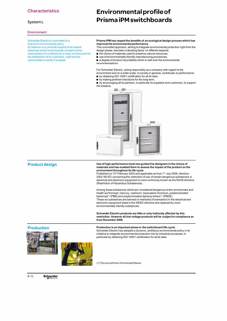
8/15/2019 Prisma iPM System L Catalogue 2011
http://slidepdf.com/reader/full/prisma-ipm-system-l-catalogue-2011 108/128E-12
Environmental profile of
Prisma iPM switchboards
Environment
Prisma iPM has reaped the benets of an ecological design process which has
improved its environmental performance.
This committed approach, aiming to integrate environmental protection right from the
design phase, has been a deciding factor on different aspects:the choice of materials used to preserve natural resources,b
use of environmentally friendly manufacturing procedures,b
a degree of product recyclability which is well over the environmentalb
recommendations.
For Schneider Electric, acting responsibly as a company with regard to the
environment and on a wider scale, to society in general, contributes to performance:
by obtaining ISO 14001 certication for all its sites,b
by making pertinent decisions for the long term,b
by encouraging all its partners, in particular its suppliers and customers, to supportb
the initiative.
Schneider Electric is committed to a
long-term environmental policy.
Its intention is to promote respect of all natural
resources and to work towards constant activeimprovement of conditions for a clean environment for
the satisfaction of its customers, staff and the
communities in which it is based.
Product design Use of high-performance tools has guided the designers in the choice of
materials and has enabled them to assess the impact of the product on the
environment throughout its life-cycle.
Published on 13th February 2003 and applicable as from 1st July 2006, directive
2002 / 95 / EC concerning the restriction of use of certain dangerous substances in
electrical and electronic equipment is more commonly known as the RoHS directive
(Restriction of Hazardous Substances).
Among these substances which are considered dangerous to the environment and
health we nd lead, mercury, cadmium, hexavalent chromium, polybrominated
biphenyls(1) (PBB) and polybrominated diphenyl ethers(1) (PBDE).
These six substances are banned or restricted (if exemption) in the electrical andelectronic equipment listed in the WEEE directive and replaced by more
environmentally friendly substances.
Schneider Electric products are little or only indirectly affected by this
restriction. However all low voltage products will be subject to compliance as
from December 2008.
Production Production is an important phase in the switchboard life-cycle.
Schneider Electric has adopted a dynamic, ambitious environmental policy in its
initiative to integrate environmental protection into its industrial processes, in
particular by obtaining ISO 14001 certication for all its sites.
(1) They are self-timer of brominated ames.
P D 3 9 5 0 2 3
P D 3 9 5 0 9 0
Characteristics
System L
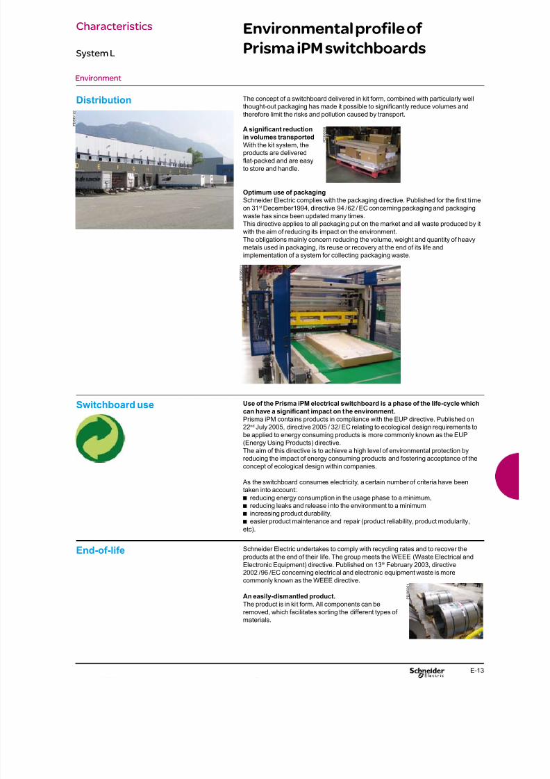
8/15/2019 Prisma iPM System L Catalogue 2011
http://slidepdf.com/reader/full/prisma-ipm-system-l-catalogue-2011 109/128E-13
Environmental profile of
Prisma iPM switchboards
Environment
Distribution The concept of a switchboard delivered in kit form, combined with particularly well
thought-out packaging has made it possible to signicantly reduce volumes and
therefore limit the risks and pollution caused by transport.
A signicant reduction
in volumes transported
With the kit system, the
products are delivered
at-packed and are easy
to store and handle.
Optimum use of packaging
Schneider Electric complies with the packaging directive. Published for the rst time
on 31st December1994, directive 94 / 62 / EC concerning packaging and packaging
waste has since been updated many times.
This directive applies to all packaging put on the market and all waste produced by it
with the aim of reducing its impact on the environment.
The obligations mainly concern reducing the volume, weight and quantity of heavy
metals used in packaging, its reuse or recovery at the end of its life and
implementation of a system for collecting packaging waste.
P D 3
9 5 1 2 2
P D 3 9 5 0 9 6
P D 3 9 5 0 1 1
Switchboard use Use of the Prisma iPM electrical switchboard is a phase of the life-cycle which
can have a signicant impact on the environment.
Prisma iPM contains products in compliance with the EUP directive. Published on
22nd July 2005, directive 2005 / 32 / EC relating to ecological design requirements to
be applied to energy consuming products is more commonly known as the EUP
(Energy Using Products) directive.
The aim of this directive is to achieve a high level of environmental protection by
reducing the impact of energy consuming products and fostering acceptance of the
concept of ecological design within companies.
As the switchboard consumes electricity, a certain number of criteria have been
taken into account:
reducing energy consumption in the usage phase to a minimum,b
reducing leaks and release into the environment to a minimumb
increasing product durability,b
easier product maintenance and repair (product reliability, product modularity,b
etc).
End-of-life Schneider Electric undertakes to comply with recycling rates and to recover the
products at the end of their life. The group meets the WEEE (Waste Electrical and
Electronic Equipment) directive. Published on 13th February 2003, directive
2002 / 96 / EC concerning electrical and electronic equipment waste is more
commonly known as the WEEE directive.
An easily-dismantled product.
The product is in ki t form. All components can be
removed, which facilitates sorting the different types of
materials.
P D 3 9 5 0 5 1
Characteristics
System L
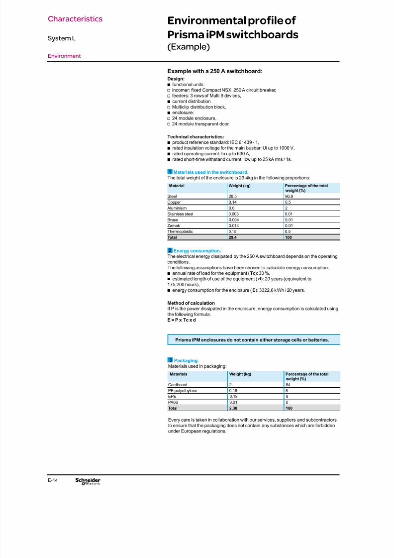
8/15/2019 Prisma iPM System L Catalogue 2011
http://slidepdf.com/reader/full/prisma-ipm-system-l-catalogue-2011 110/128E-14
Environmental profile of
Prisma iPM switchboards(Example)
Environment
Example with a 250 A switchboard:
Design:
functional units:b
v incomer: xed Compact NSX 250 A circuit breaker,
v feeders: 3 rows of Multi 9 devices,
current distributionb
v Multiclip distribution block,
enclosure:b
v 24 module enclosure,
v 24 module transparent door.
Technical characteristics:
product reference standard: IEC 61439 - 1,b
rated insulation voltage for the main busbar: Ui up to 1000 V,b
rated operating current: In up to 630 A,b
rated short-time withstand current: Icw up to 25 kA rms / 1s.b
1 Materials used in the switchboard.The total weight of the enclosure is 29.4kg in the following proportions:
Material Weight (kg) Percentage of the totalweight (%)
Steel 28.5 96.9
Copper 0.14 0.5
Aluminium 0.6 2
Stainless steel 0.003 0.01
Brass 0.004 0.01
Zamak 0.014 0.01
Thermoplastic 0.15 0.5
Total 29.4 100
2 Energy consumption.
The electrical energy dissipated by the 250 A switchboard depends on the operating
conditions.The following assumptions have been chosen to calculate energy consumption:
annual rate of load for the equipment (b Tc): 30 %,
estimated length of use of the equipment (b d): 20 years (equivalent to
175,200 hours),
energy consumption for the enclosure (b E): 3322.6 kWh / 20 years.
Method of calculation
If P is the power dissipated in the enclosure, energy consumption is calculated using
the following formula:
E = P x Tc x d
3 Packaging.
Materials used in packaging:
Materials Weight (kg) Percentage of the totalweight (%)
Cardboard 2 84
PE polyethylene 0.18 8
EPE 0.19 8
PA66 0.01 0
Total 2.38 100
Every care is taken in collaboration with our services, suppliers and subcontractors
to ensure that the packaging does not contain any substances which are forbidden
under European regulations.
Prisma iPM enclosures do not contain either storage cells or batteries.
Characteristics
System L
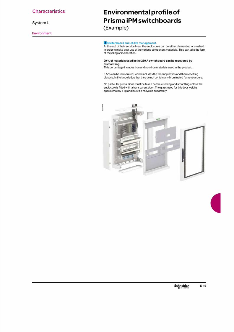
8/15/2019 Prisma iPM System L Catalogue 2011
http://slidepdf.com/reader/full/prisma-ipm-system-l-catalogue-2011 111/128E-15
Environmental profile of
Prisma iPM switchboards(Example)
Environment
P B 8 0 0 0 0 4
4 Switchboard end-of-life management.
At the end of their service lives, the enclosures can be either dismantled or crushed
in order to make best use of the various component materials. This can take the form
of recycling or incineration.
99 % of materials used in the 250 A switchboard can be recovered by
dismantling.
This percentage includes iron and non-iron materials used in the product.
0.5 % can be incinerated, which includes the thermoplastics and thermosetting
plastics, in the knowledge that they do not contain any brominated ame retarders.
No particular precautions must be taken before crushing or dismantling unless the
enclosure is tted with a transparent door. The glass used for this door weighs
approximately 4 kg and must be recycled separately.
Characteristics
System L

8/15/2019 Prisma iPM System L Catalogue 2011
http://slidepdf.com/reader/full/prisma-ipm-system-l-catalogue-2011 112/128F-2
8/15/2019 Prisma iPM System L Catalogue 2011
http://slidepdf.com/reader/full/prisma-ipm-system-l-catalogue-2011 113/128F-1
Contents
Assembling recommendations F-2 Assembling sequences F-2
Assembling tips F-8 Assemble the wall mounted enclosure Install the busbars F-8
Install the mounting plates F-9
Run and cable the power circuits F-10
Route and cable the low power and auxiliary circuits F-11
Finish and t the switchboard with panels F-12
Recommendations
System L
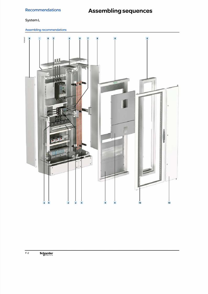
8/15/2019 Prisma iPM System L Catalogue 2011
http://slidepdf.com/reader/full/prisma-ipm-system-l-catalogue-2011 114/128F-2
1 2 4
2 5
78
923 6
8 8 8 8 8
9 10 10
Assembling sequences
Assembling recommendations
P D 8 0 0 0 6 7
Recommendations
System L

8/15/2019 Prisma iPM System L Catalogue 2011
http://slidepdf.com/reader/full/prisma-ipm-system-l-catalogue-2011 115/128F-3
Assembling sequences
Assembling recommendations
Chronology of the opposite switchboard conguration assembly:
1 - Wall mounted enclosure structureRear panel.b
2 - Mounting plates and switchgears
Mounting plate with NSX 400b
Mounting plate with Compact NSX100.b
Modular device rails.b
Multi9 and IC devices.b
3 - Distribution blocks
200 A Multiclip distribution block.b
4 - Cable duct association
Cable duct.b
Assembly kit.b
5 - Busbars
Vertical multi-stage busbar.b
6 - Wiring trunking
Trunking.b
Tunking for the ne wiring.b
7 - Power cables
Connection devices to busbar.b
Terminal blocks.b
Earth / neutral bar.b
Connection devices to terminal blocks.b
8 - Wall mounted enclosure coveringPillars.b
2 side panels.b
Top and bottom plates.b
Front frame.b
9 - Front plates
Front plates.b
10 - Doors
Transparent door.b
Plain door.b
Recommendations
System L
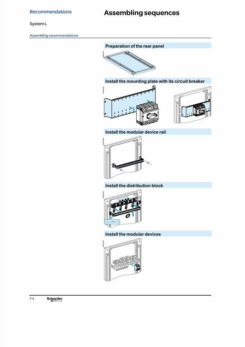
8/15/2019 Prisma iPM System L Catalogue 2011
http://slidepdf.com/reader/full/prisma-ipm-system-l-catalogue-2011 116/128F-4
Assembling sequences
Assembling recommendations
Preparation of the rear panel
Install the modular device rail
Install the modular devices
Install the distribution block
Install the mounting plate with its circuit breaker
D D 8 0 0 4 0 0
D D 8 0 0 4 8 7
D D 8 0 0 4 8 8
D D 8 0 0 4 9 0
D D 8 0 0
4 9 4
Recommendations
System L

8/15/2019 Prisma iPM System L Catalogue 2011
http://slidepdf.com/reader/full/prisma-ipm-system-l-catalogue-2011 117/128F-5
Assembling sequences
Assembling recommendations
x 2
Install the selected busbar
Install the cable duct
D D 8 0 0 4 0 3
D D 8 0 0 4 8 3
D D 8 0 0 4 8 4
D D 8 0 0 4 8 5
D D 8 0 0 4 8 6
D D 8 0 0 4 0 1
D D 8 0 0 4 0 2
Recommendations
System L
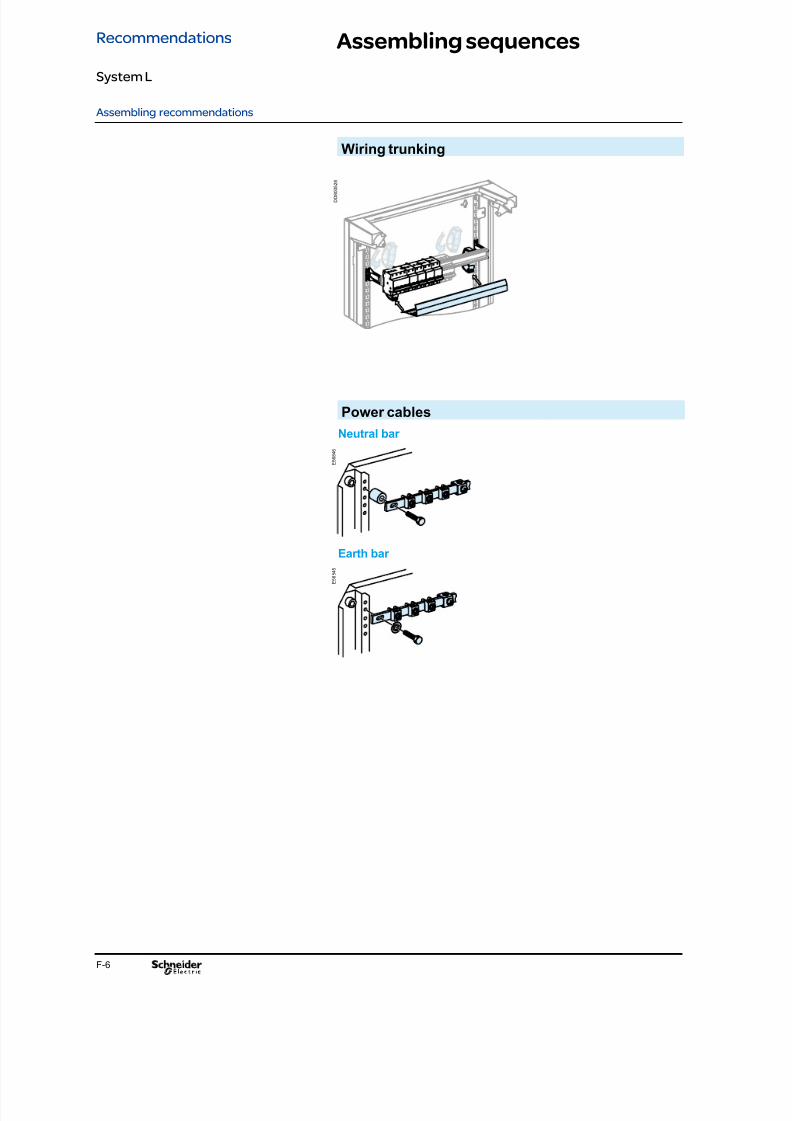
8/15/2019 Prisma iPM System L Catalogue 2011
http://slidepdf.com/reader/full/prisma-ipm-system-l-catalogue-2011 118/128F-6
Assembling sequences
Assembling recommendations
Power cables
Neutral bar
Wiring trunking
Earth bar
E 5 6 8 4 6
D D 8 0 0 5 2 8
E 5 6 8 4 5
Recommendations
System L

8/15/2019 Prisma iPM System L Catalogue 2011
http://slidepdf.com/reader/full/prisma-ipm-system-l-catalogue-2011 119/128
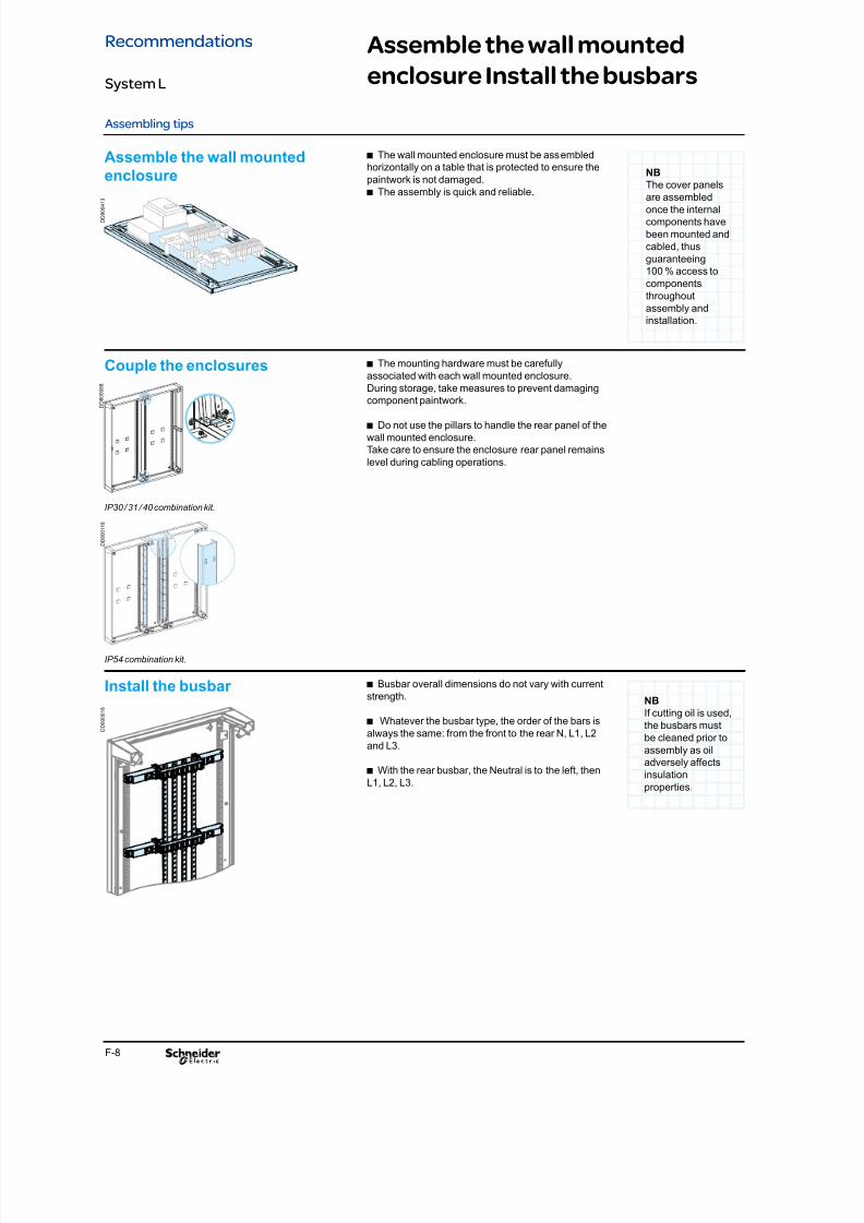
8/15/2019 Prisma iPM System L Catalogue 2011
http://slidepdf.com/reader/full/prisma-ipm-system-l-catalogue-2011 120/128F-8
Assembling tips
Assemble the wall mounted
enclosure Install the busbars
The wall mounted enclosure must be assembledb
horizontally on a table that is protected to ensure the
paintwork is not damaged.
The assembly is quick and reliable.b
Assemble the wall mounted
enclosure
The mounting hardware must be carefullyb
associated with each wall mounted enclosure.
During storage, take measures to prevent damaging
component paintwork.
Do not use the pillars to handle the rear panel of theb
wall mounted enclosure.
Take care to ensure the enclosure rear panel remains
level during cabling operations.
Couple the enclosures
NB
The cover panels
are assembled
once the internal
components have
been mounted and
cabled, thus
guaranteeing
100 % access to
components
throughout
assembly and
installation.
Busbar overall dimensions do not vary with currentb
strength.
Whatever the busbar type, the order of the bars isb
always the same: from the front to the rear N, L1, L2
and L3.
With the rear busbar, the Neutral is to the left, thenb
L1, L2, L3.
Install the busbar NB
If cutting oil is used,
the busbars must
be cleaned prior to
assembly as oil
adversely affectsinsulation
properties.
IP30 / 31 / 40 combination kit.
IP54 combination kit.
D D 8 0 0 0 1 8
D D 8 0 0 4 1 3
D D 8 0 0 0 8 8
D D 8 0 0 1 1 8
Recommendations
System L

8/15/2019 Prisma iPM System L Catalogue 2011
http://slidepdf.com/reader/full/prisma-ipm-system-l-catalogue-2011 121/128F-9
Install the mounting plates
Assembling tips
Checking switchgear position
Assemble order
The order of assembly of the mounting plates and devices depends on theb
technical features of the devices.
To dene the position of a mounting plate of a functional unit, you need to know theb
overall dimensions of the functional unit (H), i.e. the number of modules
(1 module = 50 mm). This number is given in the functional unit pages catalogue.
The reference starting point for the installation of the mounting plate (b) is given in
the leaets.
Install the mounting plates
Table showing the assembly order according to the device type:b
Device Assembly order
Compact CVS and NSX, Interpact INS andEasypact EZC and EZC y 630 A
Place the device on the mounting plate.b
Install the equipped mounting plate.b
Modular devices Install the rail system.b
Place the modular devices on the rail.b
This operation allows operators inspection and prevents incorrect positioning ofb
the functional unit with respect to the front panel, before the wall mounted enclosure
has been cabled.
D D 8
0 0 4 1 4
D D 8 0 0 4 1 5
D D 8 0 0 4 1 6
D D 8 0 0 4 9 5
Recommendations
System L
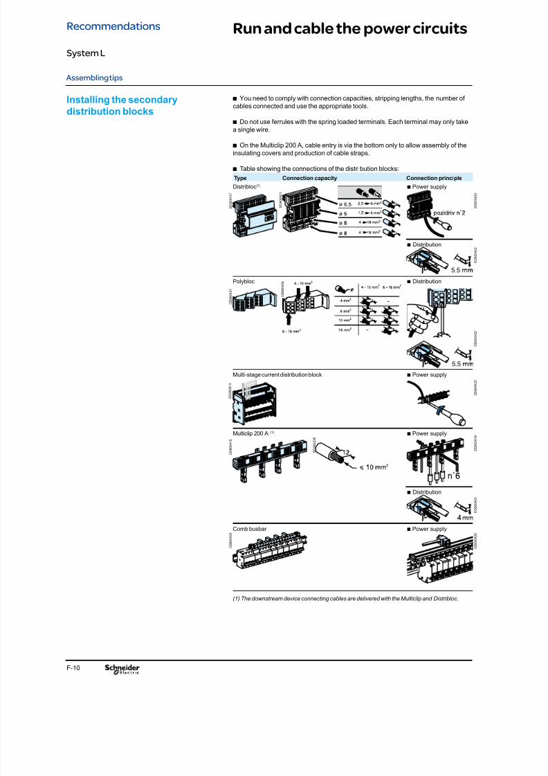
8/15/2019 Prisma iPM System L Catalogue 2011
http://slidepdf.com/reader/full/prisma-ipm-system-l-catalogue-2011 122/128F-10
Assembling tips
Run and cable the power circuits
You need to comply with connection capacities, stripping lengths, the number ofb
cables connected and use the appropriate tools.
Do not use ferrules with the spring loaded terminals. Each terminal may only takeb
a single wire.
On the Multiclip 200 A, cable entry is via the bottom only to allow assembly of theb
insulating covers and production of cable straps.
Table showing the connections of the distribution blocks:b
Type Connection capacity Connection principle
Distribloc(1)b Power supply
b Distribution
Polybloc b Distribution
Multi-stage current distribution block b Power supply
Multiclip 200 A (1)b Power supply
b Distribution
Comb busbar b Power supply
(1) The downstream device connecting cables are delivered with the Multiclip and Distribloc.
Installing the secondary
distribution blocks
D D 8 0 0 4 1 7
D D 8 0 0 4 1 8
D D 3 8 2 8 1 3
D D 8 0 0 4 1 9
D D 3 8 2 2 3 5
D D 8 0 0 4 2 1
D D 8 0 0 4 2 3
D D 8 0 0 4 2 2
D D 8 0 0 4 2 0
D D 8 0 0 4 2 5
D D 8 0 0 4 2 6
D D 8 0 0 4 2 4
D D 8 0 0 4 2 7
D D 8 0 0 4 2 2
D D 8 0 0 4 2 8
Recommendations
System L
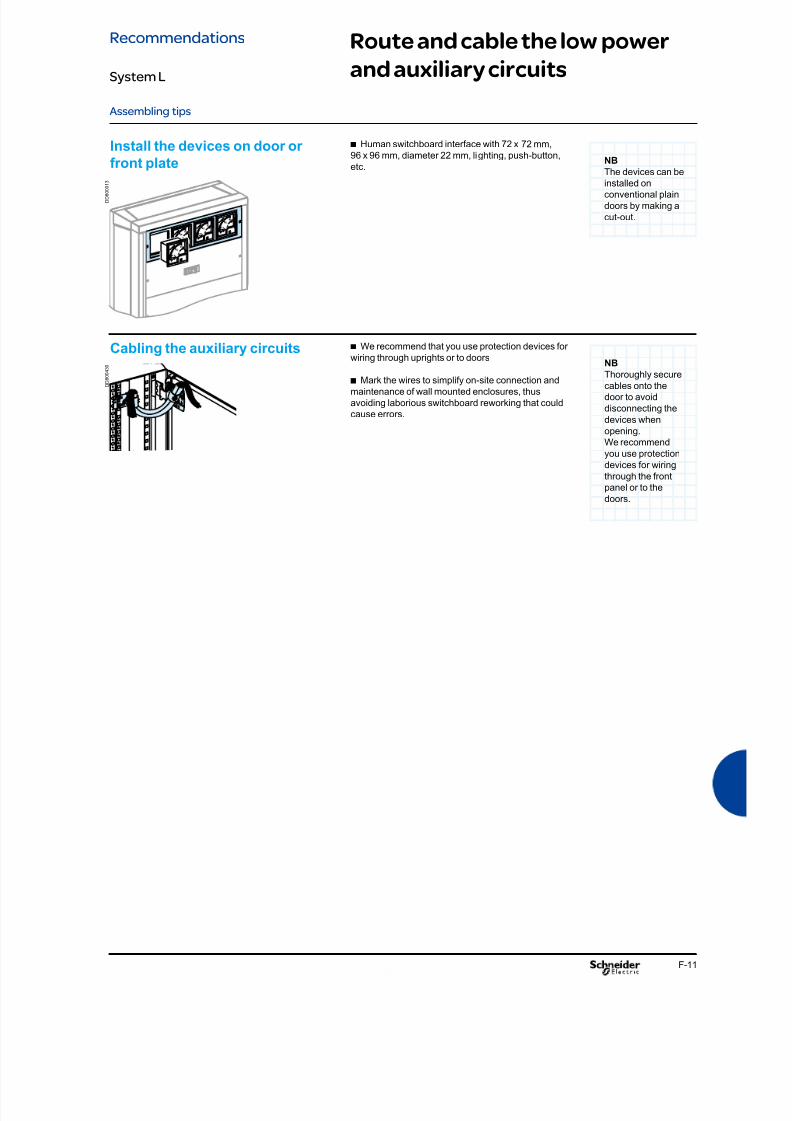
8/15/2019 Prisma iPM System L Catalogue 2011
http://slidepdf.com/reader/full/prisma-ipm-system-l-catalogue-2011 123/128F-11
Route and cable the low power
and auxiliary circuits
Assembling tips
Human switchboard interface with 72 x 72 mm,b
96 x 96 mm, diameter 22 mm, lighting, push-button,
etc.
Install the devices on door or
front plate NB
The devices can beinstalled on
conventional plain
doors by making a
cut-out.
We recommend that you use protection devices forb
wiring through uprights or to doors
Mark the wires to simplify on-site connection andb
maintenance of wall mounted enclosures, thus
avoiding laborious switchboard reworking that could
cause errors.
Cabling the auxiliary circuitsNB
Thoroughly secure
cables onto the
door to avoid
disconnecting the
devices when
opening.
We recommend
you use protection
devices for wiring
through the front
panel or to the
doors.
D D 8 0 0 4 3 0
D D 8 0 0 0 1 3
Recommendations
System L

8/15/2019 Prisma iPM System L Catalogue 2011
http://slidepdf.com/reader/full/prisma-ipm-system-l-catalogue-2011 124/128F-12
Finish and fit the switchboard
with panels
Assembling tips
Fitting the switchboard When the doors are tted, for safety reasons, ensureb
that the door opening direction will not obstruct on site
access to an evacuation corridor or passageway. The
door must open in the direction of the evacuation.
It is advisable to install barrels and inserts beforeb
tting the handle on the door and before installation on
the wall mounted enclosure.
NB
Take care to
degrease surfaces
thoroughly before
sticking on the
gaskets.
Labelling and marking Device marking: this enables users of the system tob
identify clearly the various circuits involved. Marking
should be fully legible, durable and properly attached to
the device.
Inside the switchboard: marking identies theb
devices, thus avoiding all risk of confusion when
working inside the switchboard
NB
Barriers preventing
access to live parts
should be markedwith a “DANGER”
sign.
D D 3 8 2 1 8 0
E 2 0 5 7 8
D D 8
0 0 1 9 0
D D 8 0 0 4 3 1
Recommendations
System L

8/15/2019 Prisma iPM System L Catalogue 2011
http://slidepdf.com/reader/full/prisma-ipm-system-l-catalogue-2011 125/128F-13
Notes

8/15/2019 Prisma iPM System L Catalogue 2011
http://slidepdf.com/reader/full/prisma-ipm-system-l-catalogue-2011 126/128F-14
Notes

8/15/2019 Prisma iPM System L Catalogue 2011
http://slidepdf.com/reader/full/prisma-ipm-system-l-catalogue-2011 127/128

8/15/2019 Prisma iPM System L Catalogue 2011
http://slidepdf.com/reader/full/prisma-ipm-system-l-catalogue-2011 128/128