printing from undefined - wtxmc.orgwtxmc.org/minicooperdocs/auto trans overview.pdf · transmission...
TRANSCRIPT

2006-07 GENINFO
Automatic Transmission - Overview - MINI
MINI GA6F21WA
GA6F21WA 6-SPEED AUTOMATIC GEARBOX
From January 2005, a 6-speed automatic transmission (manufacturer: AISIN AW CO. LTD, Japan) will be used for the first time in the MINI COOPER S and the MINI COOPER S Convertible.
The MINI COOPER will continue to be equipped with the ECVT (electronically controlled continuously variable automatic transmission).
The 6-speed automatic transmission is characterized by its short gearshift times (1/4 second) in conjunction with Agitronic.
Agitronic enables individual gear selection in drive position D by means of shift paddles on the steering wheel. The driver can shift manually in drive position D without having to use the selector lever to switch to Steptronic mode beforehand. There are four innovative shift modes associated with the Agitronic:
DRIVE POSITION SPECIFICATION
Drive Position "D"
Normal Automatic gear shifting. Perfect combination of comfort, sportiness and fuel consumption.
AgitronicIndividual gear selection by means of shift paddles on the steering wheel. If there is no acceleration or manual gearshift, the automatic transmission shifts back to the normal drive position D after a short time.
Drive Position "S"
SportAutomatically provides extremely sporty configuration for maximum agility and ultra-quick response by the car.
SteptronicManual gear shifting by means of shift paddles on the steering wheel or the selector lever without exiting from automatic.
2006 MINI Cooper S
2006-07 GENINFO Automatic Transmission - Overview - MINI
2006 MINI Cooper S
2006-07 GENINFO Automatic Transmission - Overview - MINI
Microsoft
Tuesday, February 16, 2010 10:24:31 AM Page 1 © 2005 Mitchell Repair Information Company, LLC.
Microsoft
Tuesday, February 16, 2010 10:24:36 AM Page 1 © 2005 Mitchell Repair Information Company, LLC.

Fig. 1: ECVT (Electronically Controlled Continuously Variable Automatic Transmission) Courtesy of BMW OF NORTH AMERICA, INC.
Changes to the Engine and the Vehicle
Extensive changes have been made to the engine and the vehicle for automatic transmission operation:
Absence of an engine oil cooler. The engine oil cooler can be omitted due to the reduced rpm range of the engine in conjunction with the automatic transmission.
Adaptation of the coolant lines with a connection for the transmission oil cooler.
Adaptation of the crankshaft flange to the new flywheel.
Modification of the engine mounting location. The engine has been moved 7 mm upwards and 10 mm to the right on account of the size of the transmission.
Transmission mounting with hydro-mounts.
Use of a suction jet pump. The vacuum pressure for operation of the brake booster may be insufficient in certain operating states. The suction jet pump uses its Venturi effect to boost the vacuum pressure at the brake servo.
2006 MINI Cooper S
2006-07 GENINFO Automatic Transmission - Overview - MINI
Microsoft
Tuesday, February 16, 2010 10:24:31 AM Page 2 © 2005 Mitchell Repair Information Company, LLC.

Air intake duct with a connection for the suction jet pump.
Adaptation of the exhaust manifold due to the new engine position.
Extended body wiring harness for transmission control.
A/C refrigerant lines have been redesigned due to engine mounting change.
Output shafts adapted to the automatic transmission.
Modification of the underbody paneling of the engine compartment. The underbody paneling has an air duct for cooling the power steering.
Technical Data
TECHNICAL DATA
System Components
Gearbox 6-speed planetary gearbox (6-speed automatic transmission) with hydrodynamic torque converter for front-wheel drive
Transmission Output
max. torque 220 Nm
Transmission Ratios
1st gear: 4.040 4th gear: 1.160 2nd gear: 2.370 5th gear: 0.850 3rd gear: 1.550 6th gear: 0.670 Reverse gear: 3.193
Lever Position P-R-N-D-M/S and SteptronicControl electrohydraulicWeight with transmission oil and torque converter: 82.6 kg (63 lbs.)
Towability 50 km at up to 50 km/hMaintenance Maintenance-free with life-time oil filling
2006 MINI Cooper S
2006-07 GENINFO Automatic Transmission - Overview - MINI
Microsoft
Tuesday, February 16, 2010 10:24:31 AM Page 3 © 2005 Mitchell Repair Information Company, LLC.

Fig. 2: 6-Speed Automatic Gearbox Components Courtesy of BMW OF NORTH AMERICA, INC.
Arrangement of components:
1. Multiple pin connector 1 to EGS control unit
2. Multiple pin connector 2 to EGS-control unit
3. Selector lever position switch 7 Selector lever unit
4. Transmission oil cooler
5. Bowden cable
6. EGS control unit
2006 MINI Cooper S
2006-07 GENINFO Automatic Transmission - Overview - MINI
Microsoft
Tuesday, February 16, 2010 10:24:31 AM Page 4 © 2005 Mitchell Repair Information Company, LLC.

Fig. 3: Section View Of Transmission Courtesy of BMW OF NORTH AMERICA, INC.
Section View of Transmission
EXPLANATION CHART Index Explanation Index Explanation
A Oil Pump S1 Sun GearB Intermediate Drive K1 Multi-plate ClutchB1 Multi-plate Brake S2 Sun GearB2 Multi-plate Brake K2 Multi-plate ClutchC Output P3 Planetary Gears S3 Sun GearF Freewheel K3 Multi-plate Clutch
2006 MINI Cooper S
2006-07 GENINFO Automatic Transmission - Overview - MINI
Microsoft
Tuesday, February 16, 2010 10:24:31 AM Page 5 © 2005 Mitchell Repair Information Company, LLC.

System IPO
PT1 Planet Carrier P1 Planetary GearsPT2 Planet Carrier P2 Planetary Gears
2006 MINI Cooper S
2006-07 GENINFO Automatic Transmission - Overview - MINI
Microsoft
Tuesday, February 16, 2010 10:24:31 AM Page 6 © 2005 Mitchell Repair Information Company, LLC.

Fig. 4: System IPO Function Courtesy of BMW OF NORTH AMERICA, INC.
Legend for System IPO
EXPLANATION CHART
DESCRIPTION OF COMPONENTS AND OPERATION
Selector Lever
The selector lever has a newly designed selector lever grip. The selector lever mechanism and the arrangement of the drive positions are identical to those of the ECVT (electronically controlled continuously variable automatic transmission).
Selector Lever Positions
The selector lever is used to select drive positions P, R, N, D and M/S.
Selector Lever Position P
The cable and the selector shaft are used to place the automatic gearbox in Park.
Selector Lever Position R
Index Explanation1 EGS control unit
2-3 Solenoid valves4-8 Pressure control valves9 Electromagnet for selector lever interlock (Shiftlock10 On-board diagnostics socket11 Earth connection12 Fuse13 Gearshift paddles on steering wheel14 Switch for sport program and manual gear changes (on selector lever)
15
Selector lever position switch with connectors:
Terminal 87
Signal for electronic immobilizer (EWS)
Terminal 15
Reversing light control 16 Automatic transmission fluid temperature sensor17 Engine speed sensor (transmission input speed)18 Engine speed sensor (transmission output speed)
2006 MINI Cooper S
2006-07 GENINFO Automatic Transmission - Overview - MINI
Microsoft
Tuesday, February 16, 2010 10:24:31 AM Page 7 © 2005 Mitchell Repair Information Company, LLC.

Reverse gear
Selector Lever Position D
Gears 1 to 6 are selected automatically accordance with the shift characteristics in selector lever position D.
Selector Lever Position D (Agitronic)
Gears can also be selected manually with the selector lever in position D: The system switches automatically to manual if the paddles on the steering wheel are operated.
The gears are selected by pushing or pulling on the paddles. The gear selected is engaged as soon as the appropriate rpm and speed are reached.
The gear selected is shown on the instrument cluster display (M1 to M6).
During overtaking or if the car is driven hard, the gear can be changed quickly without first moving the selector lever to the M/S (Steptronic) position. Pulling away is only possible in 1st or 2nd gear.
If the gears are not shifted for more than 6 seconds and the vehicle is not deliberately accelerated, the gears will be shifted automatically again.
Selector Lever Position M/S
Moving the selector lever sideways to the M/S position engages the Sport program. Upshifts are made later in the Sport program, making more sporty driving possible.
To quit M/S mode, you move the selector lever forward (-) or backward (+) or use the paddles on the steering wheel to switch to manual mode (Steptronic). You move the selector lever again or use the paddles on the steering wheel, to select gears manually. The gearbox remains in manual mode until the selector lever is returned to the D position.
Changing gears using the paddles on the steering wheel puts greater pressure on the linkages than does changing gear with the selector lever. Gear changes using the pad-
Selector Lever Position Switch
The selector lever position switch is located on the selector shaft on the transmission housing. It is connected to the selector lever via a cable. The selector lever position switch sends the signals for selector lever positions P, R, N, and D to control the transmission control and the selector lever interlock (Shiftlock) on the EGS control unit.
The selector lever position is displayed on the instrument cluster. The display is controlled by the EGS control unit via the Power Train-CAN.
The reversing lights are supplied with 12 V vehicle voltage directly by the selector lever position switch.
The P/N signal for the starter lock comes from the selector lever position switch via a line to the immobilizer
2006 MINI Cooper S
2006-07 GENINFO Automatic Transmission - Overview - MINI
Microsoft
Tuesday, February 16, 2010 10:24:31 AM Page 8 © 2005 Mitchell Repair Information Company, LLC.

control unit.
The selector lever position switch must be readjusted after replacement and installation of the automatic gearbox. Observe the Repair Instructions.
Fig. 5: Selector Lever Position Switch Courtesy of BMW OF NORTH AMERICA, INC.
Selector Lever Interlock (Shiftlock)
The shiftlock prevents the driver pulling away inadvertently by shifting the selector lever by mistake with the engine running. The selector lever is blocked by an electromagnet in positions P and N. Power to the electromagnet is supplied by the EGS from terminal 15 ON.
When the brake pedal is depressed, the power supply is interrupted and the selector lever released. At terminal 15 OFF, the lever can still be shifted to position P and is then locked.
Safety Catch (Interlock)
2006 MINI Cooper S
2006-07 GENINFO Automatic Transmission - Overview - MINI
Microsoft
Tuesday, February 16, 2010 10:24:31 AM Page 9 © 2005 Mitchell Repair Information Company, LLC.

The ignition key can only be removed with the selector lever in position P. The ignition lock housing has a bowden cable coming from the selector lever.
Starter Lock
The engine can only be started with the selector lever in positions P or N. This information is sent along a separate lead from the selector lever position switch to the electronic vehicle immobilizer (EWS) control module.
Converter Lockup Clutch
Torque from the engine is transferred to the gearbox by a torque converter fitted with a gradual lockup clutch. The lockup clutch ensures a positive lock between the engine and automatic gearbox, thus reducing consumption.
The converter lockup clutch is closed in gears 2 to 6 as a function of the following factors:
Accelerator pedal position
Transmission output speed (locked above 1800 rpm)
Drive program
Transmission fluid temperature (always unlocked below 20°C so the that the transmission oil heats up faster).
Selected gear
2006 MINI Cooper S
2006-07 GENINFO Automatic Transmission - Overview - MINI
Microsoft
Tuesday, February 16, 2010 10:24:31 AM Page 10 © 2005 Mitchell Repair Information Company, LLC.
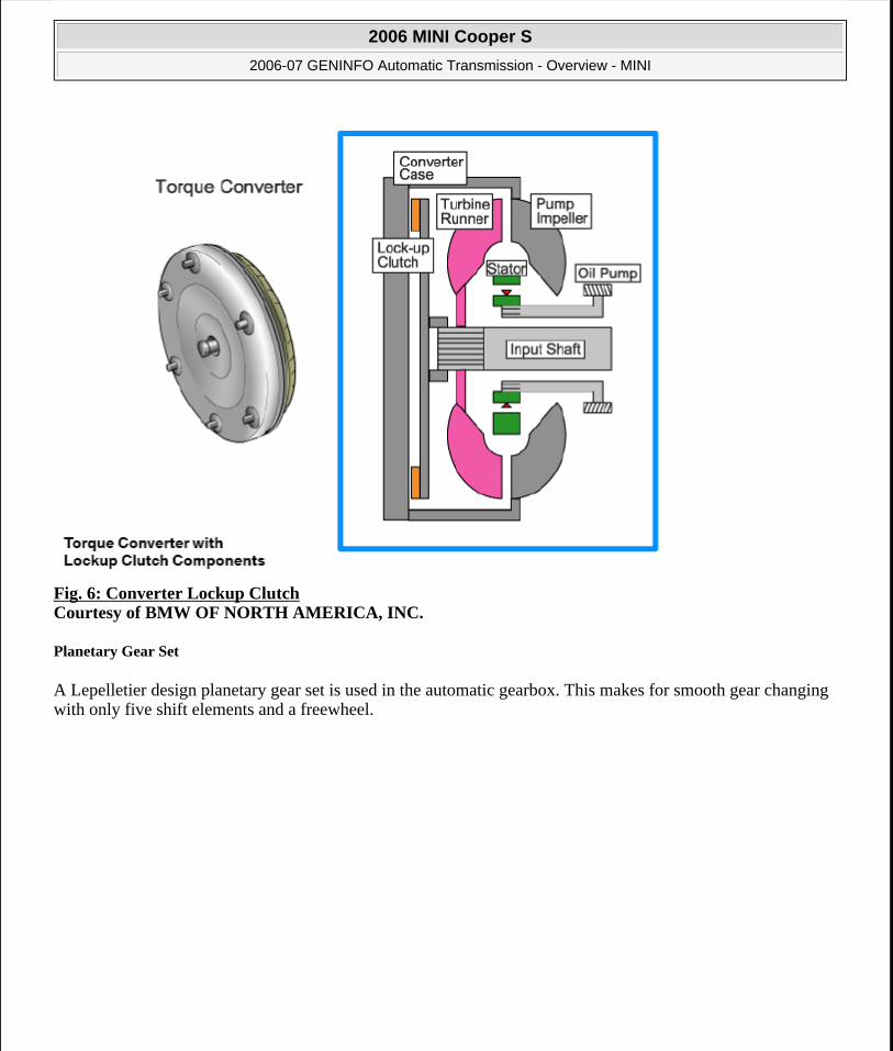
Fig. 6: Converter Lockup Clutch Courtesy of BMW OF NORTH AMERICA, INC.
Planetary Gear Set
A Lepelletier design planetary gear set is used in the automatic gearbox. This makes for smooth gear changing with only five shift elements and a freewheel.
2006 MINI Cooper S
2006-07 GENINFO Automatic Transmission - Overview - MINI
Microsoft
Tuesday, February 16, 2010 10:24:31 AM Page 11 © 2005 Mitchell Repair Information Company, LLC.

Fig. 7: Planetary Gear Set Courtesy of BMW OF NORTH AMERICA, INC.
Oil Pump
The automatic gearbox is fitted with an oil pump to supply the necessary hydraulic pressure. The oil pump is driven by the input shaft.
Transmission Oil Cooler
The transmission oil cooler is bolted to the gearbox housing. It connects to the engine coolant circuit via two lines. The transmission oil cooler speeds up transmission oil heating while the engine is warming up. When the engine reaches operating temperature, the coolant reduces the temperature of the transmission oil.
ELECTRONIC GEARBOX CONTROL (EGS)
EGS Control Unit
2006 MINI Cooper S
2006-07 GENINFO Automatic Transmission - Overview - MINI
Microsoft
Tuesday, February 16, 2010 10:24:31 AM Page 12 © 2005 Mitchell Repair Information Company, LLC.
The EGS control unit in located in the vehicle interior underneath the steering column. Data is exchanged with the following controllers on the Power Train-CAN:
DME
DSC (including. ABS / ASC)
Instrument cluster.
Throttle-valve Signal
The throttle-valve signal is the load requirement signal and is needed by the electronics when selecting gears.
Injection Signal
The injection signal is the engine load status signal. It, plus the throttle-valve signal and the pulling-away signal are needed when changing gears.
Engine Intervention
During gear changing, the transmission electronics complement the engine electronics by retarding ignition timing for about 200 ms. This reduces the engine torque momentarily, improves shift quality, the load on the transmission is reduced, and the shift time is reduced.
Kickdown
If the driver presses the accelerator pedal to the floor (kickdown), the full load voltage value of the accelerator pedal module is exceeded.
Once a voltage value set in the engine control unit is reached (4300 mV), this is interpreted by the DME as kickdown, and this information sent from the DME via the PTCAN to the EGS control unit.
Transmission Input Speed
There is a speed sensor for the transmission input speed on the gearbox input shaft. The speed sensor operates on the Hall principle. The electronic gearbox controller needs to know the exact transmission input speed for the following functions:
Control, adaptation and monitoring of gear changes
Control and monitoring of the converter lockup clutch
Diagnosis of shift elements and plausibility checking of engine and gearbox output speeds.
Gearbox Output Speed
There is a speed sensor for the gearbox output speed on the parking interlock gear. The speed sensor operates on the Hall principle. The electronic gearbox controller needs to know the exact transmission input speed for the
NOTE: The adaptive values must be reset using the BMW diagnosis system after the EGS control unit has been replaced.
2006 MINI Cooper S
2006-07 GENINFO Automatic Transmission - Overview - MINI
Microsoft
Tuesday, February 16, 2010 10:24:31 AM Page 13 © 2005 Mitchell Repair Information Company, LLC.

following functions:
Selection of gear change point
Diagnosis of shift elements and plausibility checking of engine and turbo unit output speeds.
DSC
The selected gear is limited to 4500 rpm during DSC intervention. Changing gear would have a negative effect on driving stability. The transmission changes up automatically above 4500 rpm to reduce the torque to the wheels. No special winter program is needed in the electronic transmission controller, thanks to DSC control and front-wheel drive.
Transmission Fluid Temperature
The transmission fluid temperature sensor is located in the gearbox oil in the electrohydraulic control gear. Transmission fluid temperature information is needed for the following functions:
To match the shift pressure (system pressure) and pressure increase and decrease during gear changes
To activate and deactivate temperature dependent function such as engaging the converter lockup clutch.
Brake Light Switch
The brake-light-switch signal comes from the PT-CAN. It is needed for the operation of the selector lever interlock (shift-lock) and for transmission control (e.g. gradient detection function).
Engine Speed
Engine speed data is needed in the EGS control unit for safety functions, e.g. to prevent downshifting if it could over-rev the engine.
Shift Characteristics
The EGS control unit determines the change-up and change-down points as a function of:
Driver's desired load (accelerator pedal and throttle-valve position)
Transmission output speed
Selector-lever setting
Kickdown signal
The shift points vary, depending on temperature (temperature sensor in electrohydraulic control gear).
2006 MINI Cooper S
2006-07 GENINFO Automatic Transmission - Overview - MINI
Microsoft
Tuesday, February 16, 2010 10:24:31 AM Page 14 © 2005 Mitchell Repair Information Company, LLC.

Fig. 8: Shift Characteristics In Drive Position Graph Courtesy of BMW OF NORTH AMERICA, INC.
Fig. 9: Shift Characteristics In Sport Program Graph Courtesy of BMW OF NORTH AMERICA, INC.
2006 MINI Cooper S
2006-07 GENINFO Automatic Transmission - Overview - MINI
Microsoft
Tuesday, February 16, 2010 10:24:31 AM Page 15 © 2005 Mitchell Repair Information Company, LLC.

Fig. 10: Shift Characteristics During Gradient Detection Graph Courtesy of BMW OF NORTH AMERICA, INC.
Gradient Detection
The transmission control is fitted with a gradient detection function in shift lever positions D and SD. It detects whether the vehicle is travelling uphill or downhill by comparing the engine torque and the selected gear on the one hand, and wheel speed on the other.
When travelling uphill, the controller selects the gear which best provides the vehicle with sufficient reserves of traction.
When travelling downhill, the gear is held after use of the brake or a manual downshift. The transmission changes down when brake use is detected.
Fast-off Detection
To decelerate, the driver takes his foot off the accelerator pedal and uses the brakes is necessary. Closure of the throttle caused by the change in shift characteristics, tends to make the transmission upshift.
This gear change is not desirable because it hinders the braking effect of the engine. In addition, in many cases, using the brake pedal again shortly after shifting up or down considerably increases shift frequency.
The objective of this function is, therefore, to block upshifting in the circumstances described. The driver's desire to decelerate is detected by very fast return of the pedal into the zero position (Fast-Off). If this action is detected, upshifting is suppressed while the accelerator is in the zero position and the vehicle is moving.
2006 MINI Cooper S
2006-07 GENINFO Automatic Transmission - Overview - MINI
Microsoft
Tuesday, February 16, 2010 10:24:31 AM Page 16 © 2005 Mitchell Repair Information Company, LLC.

Cornering Detection
Shifting up in corners is prevented above a defined lateral acceleration. The radius of the bend is detected from the differences in speed of the inside and outside wheels. An accurate enough calculation of the lateral acceleration is made by taking the travelling speed into consideration. Identical front wheel tire circumferences are a prerequisite for this calculation.
VALVE BODY
The valve body (electrohydraulic selector unit) is located in the automatic gearbox. It is covered by the transmission oil sump. The valve body sets the drive and brake clutches to the correct hydraulic pressure.
A selector switch is triggered in the valve body by the cable on the selector lever. The gear selector valve regulates the transmission oil (main pressure) as a function of the selector lever position in relation to the corresponding solenoid valves in the transmission.
The following components for transmission control are also located in the valve body:
Oil temperature sensor
Solenoid valves (2x)
Pressure control valves (6x).
The valve body is connected to the EGS control unit by two multiple pin connectors (on the gearbox housing).
2006 MINI Cooper S
2006-07 GENINFO Automatic Transmission - Overview - MINI
Microsoft
Tuesday, February 16, 2010 10:24:31 AM Page 17 © 2005 Mitchell Repair Information Company, LLC.

Fig. 11: Valve Body Function Courtesy of BMW OF NORTH AMERICA, INC.
Automatic Transmission Fluid Temperature Sensor
The automatic transmission fluid temperature sensor is located in the transmission oil in the electrohydraulic selector unit. It is soldered into the transmission wiring harness.
TRANSMISSION OIL TEMPERATURE CHART
Solenoid Valves
There are two solenoid valves (3/2-way valves) in the valve body for sending switching signals such as "Fill clutch" or "Bleed" to the hydraulic controller.
Transmission Oil Temperature 10°C 25°C 110°CResistance Value 5.62-7.31 (kohms) 3.5 (kohms) 0.22-0.27 (kohms)
2006 MINI Cooper S
2006-07 GENINFO Automatic Transmission - Overview - MINI
Microsoft
Tuesday, February 16, 2010 10:24:31 AM Page 18 © 2005 Mitchell Repair Information Company, LLC.

Both solenoid valves are controlled by the EGS controller. They switch either open or closed. First gear or reverse are selected when the valves are activated.
Delivery pressure is blocked in the de-energized state and the working volume connected to zero drain. When current is applied, the delivery pressure is the same as the working pressure and zero drain is blocked.
Fig. 12: Solenoid Valves Courtesy of BMW OF NORTH AMERICA, INC.
Pressure Control Valves
The pressure control valves translate an electrical current into a proportional hydraulic pressure. They are controlled by the EGS control unit and operate the valves associated with the shift elements. They are controlled by a PWM signal (300Hz at 0.1A to 1A).
There are six pressure control valves in the electrohydraulic selector unit. Valves (8, 9, 11, 12) use fluid pressure to control the 3 drive clutches and both brake clutches.
Valve (2) switches the converter lockup clutch.
Valve (3) regulates the oil pressure in the transmission as a function of the throttle-valve-position and engine torque.
The pressure control valves are used to make gear overlap and adaptive pressure control of each clutch possible.
2006 MINI Cooper S
2006-07 GENINFO Automatic Transmission - Overview - MINI
Microsoft
Tuesday, February 16, 2010 10:24:31 AM Page 19 © 2005 Mitchell Repair Information Company, LLC.

Fig. 13: Pressure Control Valves Courtesy of BMW OF NORTH AMERICA, INC.
Overlap Control
Automatic gearboxes differentiate between overlap control and freewheel control. In the case of overlap control, one clutch is partially filled while another is drained. Partial filling is maintained (pressure approximately 1 bar) until a synchronous speed is achieved. After that, the pressure for the clutch being filled can be increased to full.
Freewheel control is only used when changing from first to second gear.
Adaptive Pressure Control
Adaptive pressure control improves shift quality during the life of the vehicle. Slip times are measured during upshifting and compared with a specified value. As soon as a programmed limit value is exceeded, the pressure is first increased, then reduced to the correct value using an approximation technique. This compensates for differences in the friction pad and brings about height matching.
Diagnostics
Faults in the sensors, actuators and the EGS controller are stored in the fault code memory, and can be read using the BMW diagnostic system.
Emergency Operation Program
The solenoid and pressure control valves are no longer controlled by the EGS control unit if a fault occurs. In this case, an emergency operation program is activated and 3rd gear selected to make it possible to continue driving slowly. The display on the instrument cluster shows the letters EP (Emergency Program).
2006 MINI Cooper S
2006-07 GENINFO Automatic Transmission - Overview - MINI
Microsoft
Tuesday, February 16, 2010 10:24:31 AM Page 20 © 2005 Mitchell Repair Information Company, LLC.

SERVICE INFORMATION
Selector Lever Position Switch
The selector lever position switch must be readjusted after replacement and refitting of the automatic gearbox.
Fig. 14: Selector Lever Position Switch Courtesy of BMW OF NORTH AMERICA, INC.
Adjustment
1. Place selector lever in vehicle to Neutral.
2. Align the selector switch on the transmission to Neutral.
3. Tighten switch assembly as per tightening torque.
EGS Control Unit
The information on of the transmission control unit can be read as follows:
2006 MINI Cooper S
2006-07 GENINFO Automatic Transmission - Overview - MINI
Microsoft
Tuesday, February 16, 2010 10:24:31 AM Page 21 © 2005 Mitchell Repair Information Company, LLC.

Fig. 15: EGS Control Unit Label Courtesy of BMW OF NORTH AMERICA, INC.
The adaptive values must be reset using the BMW diagnostic system after the EGS control unit has been replaced.
Transmission
The Aisin transmission has two label on the side. One label is the factory label from AISIN and the other is the BMW Group label.
2006 MINI Cooper S
2006-07 GENINFO Automatic Transmission - Overview - MINI
Microsoft
Tuesday, February 16, 2010 10:24:31 AM Page 22 © 2005 Mitchell Repair Information Company, LLC.
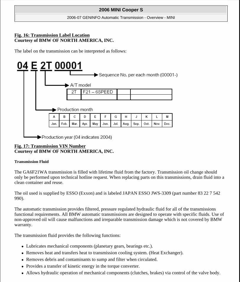
Fig. 16: Transmission Label Location Courtesy of BMW OF NORTH AMERICA, INC.
The label on the transmission can be interpreted as follows:
Fig. 17: Transmission VIN Number Courtesy of BMW OF NORTH AMERICA, INC.
Transmission Fluid
The GA6F21WA transmission is filled with lifetime fluid from the factory. Transmission oil change should only be performed upon technical hotline request. When replacing parts on this transmissions, drain fluid into a clean container and reuse.
The oil used is supplied by ESSO (Exxon) and is labeled JAPAN ESSO JWS-3309 (part number 83 22 7 542 990).
The automatic transmission provides filtered, pressure regulated hydraulic fluid for all of the transmissions functional requirements. All BMW automatic transmissions are designed to operate with specific fluids. Use of non-approved oil will cause malfunctions and irreparable transmission damage which is not covered by BMW warranty.
The transmission fluid provides the following functions:
Lubricates mechanical components (planetary gears, bearings etc.).
Removes heat and transfers heat to transmission cooling system. (Heat Exchanger).
Removes debris and contaminants to sump and filter when circulated.
Provides a transfer of kinetic energy in the torque converter.
Allows hydraulic operation of mechanical components (clutches, brakes) via control of the valve body.
2006 MINI Cooper S
2006-07 GENINFO Automatic Transmission - Overview - MINI
Microsoft
Tuesday, February 16, 2010 10:24:31 AM Page 23 © 2005 Mitchell Repair Information Company, LLC.
Also, transmission fluid has various properties to prevent oxidation and breakdown from heat and friction. Each type of transmission fluid has properties specific for each transmission application.
Fluid level is crucial in the proper operation of an automatic transmission. Improper fluid levels will cause improper operation and eventually irreparable transmission damage.
Improper fluid level can cause:
A low fluid level can cause an interruption in oil flow during fast acceleration or hard braking which can cause gear shift malfunctions and noises.
An excessively high fluid level can cause the rotating mechanical components to paddle in the oil. This produces foam which introduces air into the hydraulic system.
A low fluid level can also cause transmission overheating causing premature transmission failure.
Transmission Fluid Checking Procedures
Transmission fluid checking is accomplished using the DISplus or GT1. The DISplus or GT1 is used to monitor transmission fluid temperature to insure the transmission is not over or under-filled. There is no dipstick, the fluid level is checked by monitoring the overflow coming from the overflow hole while filling via the fill plug.
Transmission fluid should be checked between 35 and 45°C. Use the DISplus and/or GT1 to determine transmission temperature. The transmission temperature information can be found in the diagnosis section under Service Functions.
When checking transmission fluid, observe the following items:
Transmission in Park
Parking brake applied
Vehicle level
No engine load
Trans Temp 35-45°C
Observe correct drain plug torque
Use correct fluid
2006 MINI Cooper S
2006-07 GENINFO Automatic Transmission - Overview - MINI
Microsoft
Tuesday, February 16, 2010 10:24:31 AM Page 24 © 2005 Mitchell Repair Information Company, LLC.

Fig. 18: Overflow Plug (Oil Pan) Courtesy of BMW OF NORTH AMERICA, INC.
Fig. 19: Fill Plug Courtesy of BMW OF NORTH AMERICA, INC.
Transmission Fluid Checking Procedures (cont.)
1. Park the vehicle on a flat load and lock the tires.
2. Shift the shift lever to "P" range. Do not start engine.
3. Remove the overflow plug and filling plug.
4. Check if automatic transmission fluid drops from the overflow hole.
If Automatic transmission fluid does not drop, additional automatic transmission fluid to be filled until automatic transmission fluid drops.
5. Start the engine.
2006 MINI Cooper S
2006-07 GENINFO Automatic Transmission - Overview - MINI
Microsoft
Tuesday, February 16, 2010 10:24:31 AM Page 25 © 2005 Mitchell Repair Information Company, LLC.

6. Check if automatic transmission fluid drops again from the overflow hole.
If Automatic transmission fluid does not drop, additional automatic transmission fluid to be filled until automatic transmission fluid drops.
7. At this point try to maintain automatic transmission fluid in less than 35°C.
8. Shift all range from "P" to "D" with the expenditure of more than 2 seconds per each range and return to "P" after performing the 2 times shifting with foot braking.
9. Check automatic transmission fluid drops from the overflow hole.
If automatic transmission fluid drops: Confirm the automatic transmission fluid at temperature between 35-45°C with oil temperature sensor and wait until automatic transmission fluid does dribble out from overflow plug.
10. Coat a new "O" ring with automatic transmission fluid, and install it to the fill plug.
11. Using a hexagon wrench, install the overflow plug.
NOTE: Be sure to wipe off spilled automatic transmission fluid completely after tighten fill plug.
2006 MINI Cooper S
2006-07 GENINFO Automatic Transmission - Overview - MINI
Microsoft
Tuesday, February 16, 2010 10:24:31 AM Page 26 © 2005 Mitchell Repair Information Company, LLC.