printable programmable viscoelastic materials for...
TRANSCRIPT

Printable Programmable Viscoelastic Materials for Robots
Robert MacCurdy∗, Jeffrey Lipton∗, Shuguang Li and Daniela Rus
Abstract— Impact protection and vibration isolation are animportant component of the mobile robot designer’s toolkit;however, current damping materials are available only inbulk or molded form, requiring manual fabrication steps andrestricting material property control. In this paper we demon-strate a new method for 3D printing viscoelastic materialswith specified material properties. This method allows arbitrarynet-shape material geometries to be rapidly fabricated andenables continuously varying material properties throughoutthe finished part. This new ability allows robot designers totailor the properties of viscoelastic damping materials in orderto reduce impact forces and isolate vibrations. We present acase study for using this material to create jumping robotswith programmed levels of bouncing.
I. INTRODUCTION
Robots have to cope with various situations that requiredamping in locomotion and manipulation. For locomotion,bouncing can help propel the robot to the next step [1]although in other applications landing with minimal rebounds(“sticking the landing”) is important. When manipulatingvibrating tools it is desirable to absorb the vibrations of thetools. In this paper we present and analyze a new fabricationmethod for materials whose viscoelastic properties can bespecified in software and realized automatically; in otherwords the mechanical properties can be programmed. Wethen apply this approach to building jumping robots whosebodies can absorb the forces generated upon contact withthe ground. Our method is a 3D printed approach thatcombines the printing of solids with liquids to achievematerials with graded viscoelastic properties. These materialshave a storage modulus E
′ ∈ {0.1, ...,1} MPa and a tangentdelta tan(δ ) ∈ {0.2, ...,0.9}, at 1Hz. We use a data-drivenapproach to develop a model for the placement of solidand liquid droplets deposited by a 3D inkjet printer thatwill achieve a desired mechanical property within this range,and we measure the mechanical properties of these printedmaterials. Finally, we use these materials to create a newjumping cube robot that can ”stick the landing”.
In this paper we contribute:• A new fabrication method for printing viscoelastic ma-
terials• Data-driven models that describe the mechanical prop-
erties of these materials
∗These authors contributed equally to this workAuthors are from the Computer Science and Artificial Intelligence Labo-
ratory, Massachusetts Institute of Technology, The Stata Center, Building 32,32 Vassar Street, Cambridge, Massachusetts 02139, USA (maccurdy,jlipton, lisg, rus)@mit.edu
This work was supported by the National Science Foundation, grantnumbers IIS-1226883 and CCF-1138967
• Algorithms for generating the printable material designfiles
• Measurements that characterize these materials in dy-namic low- and high-strain regimes.
• A comparative study of the application of these materi-als to a jumping robot
A. Prior Work
Soft and hard jumping robots have been made for a widevariety of purposes but none have used custom viscoelasticdamping to improve their performance and durability. The”Sand Flea” robot launches itself over obstacles with apressurized air cannon, and uses its rigid plastic wheels toabsorb the impact [2]. Others such as the Mowgli use anarticulated spring system on legs to absorb the impact forces[3]. The Jollbot encloses the entire lightweight robot intoa much larger cage, limiting the space it can fit into andrequiring it to operate in a smooth environment to ensurenothing penetrates the cage [4]. Soft robots can sustain largefalls and hard impacts due to their light weight and lackof rigid structure [5]. Their elastomeric bodies can easilydeform without damage but can flail on impact causing themslide off of their targets. [6].
Power sources such as motors and pumps canshake a system adding unwanted noise and dynamics[7],[8],[9],[10],[11]. This can lead robots to be difficultto control. Traditionally discrete spring mass dampersystems have been used to adjust vibration responses inlarger structures [12]. Others have used active acousticcancellation to eliminate vibrations in structures [13].However, simple passive damping materials are the mostcommonly used and robust approach to reduce vibrations[14], [15], yet these materials are only commerciallyavailable with specific material properties and dimensions.
II. BACKGROUND
Dampers are energy-absorbing elements that convert me-chanical work into heat, dissipating that thermal energyin the ambient environment. Energy dissipating damperscan be implemented in various ways through the use ofliquid (hydraulic), gas (pneumatic), and viscoelastic (rubber,plastic, foam) materials. Dampers based on gasses or liquidsforce the working fluid through an orifice, causing flowsthat generate heat. Because they must constrain the workingfluid, devices based on this principle usually contain multipleparts including sliding seals and cylinders, which contributeto component cost and size [16]. In contrast, viscoelasticmaterials are inherently dissipative: they have a stress-strainrelationship that exhibits a phase lag, creating a hysteretic

loop [17]. This relationship can be seen in Equation 1,where σ is stress, ε is strain, and the Young’s modulus,E∗, is represented as a complex number. E ′ represents thein-phase response of the material and is known as thestorage modulus. It is the component of E∗ that stores andreleases energy when compressed. E ′′ is the loss moduluswhich represents the out of phase dissipative response of thematerial to deformation.
σ = εE∗,E∗ = E ′+ iE ′′ (1)
Viscoelastic materials are widely used as dampers becausethey are simple, compact, inexpensive, and widely available;most natural rubbers are viscoelastic. As bulk materials, theycan be shaped into the desired net geometry by conventionalmethods (casting, cutting/stamping, extruding, heat-forming,molding etc). However, this simplicity comes at a cost. Thetooling required to create the desired geometry can be time-consuming to setup, and the materials have isotropic materialproperties; if regions with varying stiffness or damping aredesired, they must be implemented with physically differentpieces of material, placed adjacent to each other.
Additive manufacturing (3D printing) provides a means toovercome these limitations. By providing a mechanism forsimultaneously depositing different materials (with differentmechanical properties) within a design, multi-material ad-ditive manufacturing allows computer code to specify themechanical properties of every region of a part using anew composite “Programmable Material”. This new materialcan have mechanical properties that vary continuously as afunction of position by controlling the proportions of eachconstitutive element.
III. USING THIS METHODWe recently showed that a commercially available inkjet
3D printer could be modified to simultaneously print withdifferent solid and liquid materials. We used the liquidmaterial, within a rigid shell, as a force-transmitting el-ement via hydraulic pressure [18]. In this paper we usea similar approach to configure the printer (Objet Connex260, Stratasys Corp.), but employ continuous distributionsof a flexible material (TangoBlack+, Stratasys Corp.) and aliquid material (Model Cleaning Material, Stratasys Corp.)by depositing adjacent droplets of each material type. Multi-material objects fabricated in this manner are specified byan occupancy matrix in R3. The entries of this matrix corre-spond to the voxels of the part that will be built. Materialswith mechanical properties that differ from the base materials(in this case, TangoBlack+ and liquid) can be specified byassigning different fractions of randomly chosen voxels toone material type or the other, assuming that the chosenvoxels lie within the bounding surface of the part (STLfile) that will be fabricated, according to Algorithm 2. Thisapproach allows customized printed viscoelastic materials(PVMs) to be designed and fabricated using modificationsof an existing toolset.
This method is used according to Algorithm 1. We providean overview here; specific examples of impact-absorbing
applications and vibration isolation are shown in sections V-A and V-B. First, the designer must determine whetherthe viscoelastic material is likely to be used in small (ε <0.01) or large deformations (ε > 0.01). Vibration dampingapplications will typically fall into the former category,while impact absorbing cases fit the latter. Next, the desiredmaterial property is chosen, and the liquid percentage thatdetermines it is obtained in the following way.
In the small deformation regime (ε < 0.01), E∗ is acomplex function of frequency and liquid percentage, asshown in Equation 2. E∗ can be expanded, using the param-eters and models from Table II. Note that when expandingEquation 5, the constant values a, b, c, and d are model-specific and must be read from the corresponding row of thetable. Similarly, the models for n1 and n2 are specific to theliquid concentration used. Equation 5 cannot be algebraicallysolved for Pl , but can be numerically evaluated across therange of its inputs ω ∈ [0, ...,2π ∗ 100], PL ∈ [0, ...,50], andthen satisfying liquid percentages can be read from a lookuptable.
We chose to characterize the coefficient of restitution forimpact applications (large deformation regime, ε > 0.01),since e∗ is defined as the ratio of energy in an object beforeand after a collision. Equation 6 shows the model for PVMsin this application, which may be evaluated to return therequired Pl for a desired e∗.
The liquid percentage is used, along with a user-generatedobject outline STL file, as an input to Algorithm 2, yieldingthe occupancy matrix M(v). M(v) is an element-by-elementlist of all voxels in the printer’s build envelope, and identifieswhich material type will be deposited in each possible voxel.The voxels define the minimum resolution of the printer.Finally, M(v) is converted into the surface files (STL format,one per material) used to print the part.
The present method uses Pl as the only determining prop-erty of the printed material. Algorithm 2 works by randomlyassigning a certain percentage of the voxels in the part tothe liquid, and the rest to the solid. This approach producesa material with isotropic mechanical properties. Though wedo not include them here, other variations of this algorithmyield voxel distributions that lead to interesting anisotropicmaterial properties.
Algorithm 1 Procedure to use this method1: if Small strain then2: Choose desired E
′, E
′′or tan(δ )
3: Compute Pl numerically from Equation 5 and Table II4: else if Large strain then5: Choose desired e∗ or Ft6: Compute Pl numerically from Equation 67: end if8: Generate a desired object shape using CAD tools and
export an STL file9: M(v)← Algorithm 2(ST L,Pl)
10: Convert M(v) into constitutive STL files11: Print STL files

Algorithm 2 Calculate M(v) ∈ R3, given ST L and Pl
1: for all voxels v in M do2: if v is inside ST L then3: r← random ∈ [0,1]4: if r > Pct then5: M(v)←Material A6: else7: M(v)←Material B8: end if9: else
10: M(v)← Empty11: end if12: end for
TABLE IVARIABLE NAMES AND DEFINITIONS
Variable Names
E∗ Complex Young’s Modulus
E′
Storage Modulus
E′′
Loss Modulus
σ Stress
ε Strain
E0 Impacter energy before collision
∆E Change in impacter energy
e∗ Coefficient of restitution e∗ ≡ ∆E/E
Ft Peak transmitted force
tan(δ ) tan(δ )≡ E′′/E′
ω Frequency (rad/sec)
i Imaginary number i≡√−1
Pl Percent liquid by volume in a material Pl ∈ [0, ...,100]
a, b, c, d Model-fit constants
A0 Undeformed cross-sectional area of sample
L0 Undeformed length of sample
M(v) Occupancy matrix defining voxel materialassignments in the printed part
IV. MODELING
The 3D printer deposits droplets of UV-cured resin cre-ating voxels that are approximately 30 x 30 x 40 µm(X,Y,Z). When non-curing liquids and UV-curing materi-als are in close proximity, as they would be during thefabrication of a PVM with high liquid concentration, pre-curing mixing between these materials is likely to occur. Itis also likely that some fraction of the liquid is absorbedinto the solid soon after printing. Therefore, although the3-dimensional pattern of voxels is prescribed by M(v), themicroscopic structure of the 3D printed materials realized bythis method is currently unknown. Additionally, modelingviscoelastic materials with a bottom-up approach, basedon finite elements or lumped parameters is an active areaof research and is application-specific [19], [20]. Thoughdeveloping a material model from first-principles would be
an interesting area of research, in this paper we chose to char-acterize the achievable material properties experimentally,and used those measurements to build phenomenologicalmodels of the material for impact- and vibration-absorbingapplications (see Table II and Equations 2 - 6).
A. DMA Measurements
In order to characterize the material’s response to vibra-tions, we tested printed samples on a TA Q800 DynamicMechanical Analyzer (DMA). Five samples of each con-centration were printed on a Connex 260 3D printer fortesting. We 3D printed samples at 0 through 50% liquidconcentrations in increments of 5%. Each sample was 10 mmin diameter and 10 mm tall, in accordance with DIN 53 513.The samples were tested in accordance with ASTM standardD5992-96. Test frequencies were varied from 1 Hz to 100Hz on an evenly spaced log scale of frequencies with 10frequencies per decade. Each sample was compressed 75µmat 22 ◦C.
As seen in Figure 1(a) and 1(b) the storage modulus E ′
and loss modulus E” lie along lines in a loglog plot forall of the frequencies and liquid concentrations tested. Thisclearly shows that there is a power law relationship of theform of Equation 2. Each line varies in slope, indicatingthat there is a different power law exponent for each ofthe concentrations of liquid. The higher slopes of the fitsin Figure 1(b) shows that there is a faster increase in E ′′
with frequency than E ′. If we can model E ′ and E ′′ at 1Hz, and the power law exponents n1 and n2, as a functionof the liquid concentration, we are able to predict the valueof E∗ at any frequency greater than 1 Hz. Figure 1(c) and1(d) show that both moduli can be fit to a model in terms ofthe liquid concentration. The model is a function of Pl of theform aebPl +cedPl . The coefficients a,b,c,d can be found inTable II.
E∗(ω,Pl) = E ′(ω,Pl)+ i∗E ′′(ω,Pl) (2)E ′(ω,Pl) = E ′|1Hz ∗ω
n1 (3)E ′′(ω,Pl) = E ′′|1Hzω
n2 (4)E∗(ω,Pl) = E ′|1Hz ∗ (ωn1 + i∗ tan(δ )|1Hzω
n2) (5)(see Table II for n1, n2)
We can see in Figures 1e and 1f that the relationship ofn1 and n2 with Pl are modeled differently for concentrationsbelow 25% and above 25%. This suggests a physical changein the material at 25%. Modeling the power terms as linear(E ′′) or quadratic (E ′) with Pl when Pl ≤ 25%, producesan acceptable fit, while the linear model for behavior above25% does not hold. The coefficients of the models can beseen in Table II. We observed under optical magnificationthat at liquid concentrations below 25%, PVMs look likea single soft material, while at concentrations above 25%liquid films form on their surface and the PVMs slowlyleak liquid over time. We were not able to directly observe,but we hypothesize that at liquid concentrations higher than25% PVMs form an open-cell foam, providing an exit path

100 101 102
Frequency (Hz)
10-1
100
101E
' (M
Pa)
Graph of E' vs Frequency0 %0 % model5 %5 % model10 %10 % model15 %15 % model20 %20 % model25 %25 % model30 %30 % model35 %35 % model40 %40 % model45 %45 % model50 %50 % model
100 101 102
Frequency (Hz)
10-1
100
101
E''
(MP
a)
Graph of E'' vs Frequency0 %0 % model5 %5 % model10 %10 % model15 %15 % model20 %20 % model25 %25 % model30 %30 % model35 %35 % model40 %40 % model45 %45 % model50 %50 % model
(a) (b)
Percent Liquid0 10 20 30 40 50
E' (
MP
a)
0
0.2
0.4
0.6
0.8
1
1.2
1.4E' at 1 Hz
E'E' model
Percent Liquid0 10 20 30 40 50
E''
(MP
a)
0
0.2
0.4
0.6
0.8
1
1.2
1.4E'' at 1 Hz
E''E'' model
(c) (d)
Percent Liquid0 10 20 30 40 50
n of
E'
0.3
0.35
0.4
0.45
0.5power law n for E'
nFit of pre 25%Fit of post 25%
Percent Liquid0 10 20 30 40 50
n of
E''
0.6
0.65
0.7
0.75
0.8power law n for E''
nFit of pre 25%Fit of post 25%
(e) (f)
Percent Liquid0 10 20 30 40 50
tan /
0
0.2
0.4
0.6
0.8
1tan / at 1 Hz
tan /tan / model
Percent Liquid-10 0 10 20 30 40 50 60
tan /
0
2
4
6Graph of tan / vs percent liquid
1.0 Hz1.6 Hz2.5 Hz3.0 Hz6.3 Hz10.0 Hz15.8 Hz25.0 Hz39.8 Hz63.0 Hz100.0 Hz
(g) (h)
Fig. 1. The complex modulus of the material varies as a function of liquid percentage. The storage modulus E ′ (a) and loss modulus E ′′ (b) can bemodeled as a power law function of frequency for all of the material concentrations tested. The power exponent n for the storage modulus (e) loss modulus(f) can be fit as two different models which switch at 25% concentration. The value of E ′ at 1 Hz (c) and E ′′ at 1Hz can be modeled as a function ofpercentage liquid. The tanδ at 1 Hz (g) can be modeled and applied over the range of frequencies (h)

TABLE IITHE PHYSICAL PROPERTIES OF THE COMPLEX MODULUS E∗ CAN BE
MODELED AS A FUNCTION OF Pl
PhysicalProperty
PhysicalProperty
Modela b c d Range of Pl
E ′|1Hz aebPl + cedPl 0.595 -0.282 0.635 -0.031 0%-50%
E ′′|1Hz aebPl + cedPl 1.00 -0.272 0.135 -0.021 0%-50%
tan(δ )|1Hz aebPl + cedPl 0.832 -0.118 0.085 0.032 0%-50%
n1 of E ′ aP2l +bPl + c 2.21e−4 −1.37e−2 0.494 - 0%-25%
n2 of E” aPl +b −3.82e−3 7.51e−1 - - 0%-25%
n1 of E ′ aPl +b 4.30e−3 1.85e−1 - - 25%-50%
n2 of E” aPl +b 0 6.73e−1 - - 25%-50%
for the deposited fluid. This could provide one explanationfor the different models required above and below the 25%concentration.
From these results we can conclude that printable vis-coelastic materials (PVM) can be modeled as a soft glassymaterial (SGM) because the storage and loss moduli of SGMmaterials have a power law relation with frequency [21]. Thehigh value of n1 and n2 (see Table II) also indicate that thematerials should not have a significant aging effect [21].
In order to simplify calculations it is convenient to replaceE ′′|1Hz with E ′|1Hz ∗ tan(δ )|1Hz. This allows us to combineEquations 2, 3, and 4 to get Equation 5. Figure 1(g) showsthat tan(δ )|1Hz can be modeled by a double exponentialfunction as well.
B. Impact Measurements
In contrast to the low-strain, controlled-rate cyclic testingperformed on the DMA, impact loads are often rapid, highmagnitude, one-time events. In order to characterize theimpact protection that PVMs could provide, we performedimpact tests using a custom built testing apparatus. Thetest consisted of 44.4g or 223g masses suspended fromnylon lines that were dropped from predetermined heightsat samples which were mounted on a quartz crystal forcesensor. The sensor, sampled at 48 kHz by at 14 bit USBDAQ card, was attached to a granite slab to ensure there wasno compliance in the sensor mount. Test PVM samples were63.5 mm in diameter (A0 = 3.17e−3 m2), 12.7 mm in height(L0 = 1.27e−2 m). The masses were dropped from heightsof 100 mm through 500 mm in increments of 100 mm. Highspeed videos (1820 fps) of the impact were collected via anEdgertronic high speed camera and processed in MATLABto determine incoming and outgoing velocities of the masses.The coefficient of restitution e∗ = |Vout/Vin| was calculatedfrom the processed video data and plotted against Pl forthe nine different impact energy cases in Figure 2 (a). Aquadratic model, shown in Equation 6, fit this data witha standard error of RMSE = 0.0136 and yields a mappingbetween the coefficient of restitution in impacts, e∗, and Pl .
As seen in Figure 2, the coefficient of restitution finds aminimum in the range of 4% to 10% liquid concentration,
indicating that this range of liquid concentration yields ma-terials with the highest energy absorption. The peak impactforce on the sample is directly correlated with the stiffness ofthe sample. Since we can model the sample as a spring withk ∝ E∗ the stopping distance of the impacting mass shouldbe inversely proportional to E∗ and the force is inverselyproportional to the stopping distance. Therefore the weakersamples which we can produce at high liquid concentrationsprovide lower peak forces (and presumably greater impactpenetration distances). Figure 2 shows a decrease in peakforce with liquid concentration as expected.
e∗ = p1P3l + p2P2
l + p3P1l + p4 (6)
p1 =−1.23e−5, p2 = 8.05e−4, p3 =−8.55e−3, p4 = 1.5e−1
The reduction in peak force can be a significant protectionfor mobile robots. In our experiments, we see a 700N reduc-tion in peak force by varying from 0% to 25% liquid con-centration. This can be the difference in a circuit surviving ashock, a sensor lens cracking upon impact with the ground,or a strut breaking off of a quadrotor. While traditionalelastomers can be placed on robots for protection, their highlevel of recoil can lead to the object simply bouncing off theground in an uncontrolled manner, causing further damage.A gradual stop without high recoil is preferred to protectany robot from both planned and unplanned ground contact.The programmable relationship between e∗ and peak force,allows designers of mobile robots to make a tradeoff betweenrecoil and peak force.
V. APPLICATIONS
A. Impact Protection for a Jumping Robot
We used our recent jumping robot [1] to demonstratethe utility of PVMs in this application by printing impactabsorbing skins. 3D printing these parts allowed more rapiddevelopment of the skin than was possible during the originalfabrication, which involved printing molds and casting acommercially available elastomer (Soma Foama, Smooth-On Corp.). Our robot has a cubic shape, and each of itssix faces has an opening to allow the jumping mechanism tomake contact with the ground. By winding up and releasing astrip spring, the robot can jump in two directions, regardlessof orientation. The robot has a main rigid body, 3D printedusing ABS materials, that houses the actuation, control, andpower. The rigid body is then encased in a soft skin forlanding. We used 4 layers of looped metal strip as the springin each half of our robot. The strips are made of stainlesssteel 316, and they are 12.7 mm wide, 0.254 mm thick, and60 mm long. We used two micro DC gear motors (1.1 N-m) to drive the metal strips. The microcontroller (ArduinoPro Micro, 3.3V/8MHz), rechargeable battery (3.7V, 400mAh), regulator (9V), motor driver (DRV8833), wirelesscommunication module (XBee 1mW, 2.4G Hz), and 9-axisIMU sensors (L3GD20H and LSM303D) are mounted withinthe space between the bottom plates of two halves.

Percent Liquid-5 0 5 10 15 20 25 30 35 40
Co
effi
cien
t o
f R
esti
tuti
on
, e*
-0.1
-0.05
0
0.05
0.1
0.15
0.2
0.25
0.3
0.35
0.4
Impact test: Coefficient of Restitution vs Percent Liquid vs Impact Energy
E=0.04361 JE=0.08722 JE=0.13083 JE=0.17444 JE=0.21785 JE=0.21805 JE=0.43571 JE=0.65356 JE=0.87142 J
Impact Energy (J)
y = p1*x3 + p2*x2 + p3*x + p4
(a)
Percent Liquid-5 0 5 10 15 20 25 30 35 40
Pea
k T
ran
smit
ted
Fo
rce
0
200
400
600
800
1000
1200
Impact test: Transmitted force vs Percent Liquid vs Impact Energy
E=0.04361 JE=0.08722 JE=0.13083 JE=0.17444 JE=0.21785 JE=0.21805 JE=0.43571 JE=0.65356 JE=0.87142 J
Impact Energy (J)
(b)Fig. 2. Impact test results. Nine different mass/drop height combinationswere used with 5 sample types. The coefficient of restitution (a) and theforce transmitted through the sample (b) and are shown, along with acurve fit for e∗. Notice that the amount of energy absorbed by the samplereaches a maximum when the sample contains ≈ 6 percent liquid. Sampletypes: {0=100% TangoBlack+; 4=96% TangoBlack+, 4% liquid; 14=86%TangoBlack+, 14% liquid; 25=75% TangoBlack+, 25% liquid; 36=64%TangoBlack+, 36% liquid}
We fit this jumping robot with different PVM skins (Pl ∈[0%, 18%, 25%, 36%]) and compared them to the originalelastomeric foam design. We used the accelerometer insidethe robot to measure the peak acceleration (as a proxyfor likely damage) and the number of bounces after eachjump. By minimizing acceleration, a designer can predictthat the robot will have a longer cycle life before failure.Additionally, a lower peak acceleration on landing reducesthe damage to the surface the robot lands on. The number ofbounces after landing serves as a metric for the maintenanceof orientation and position during the landing process.
All of the printed skins outperformed the original elas-tomeric foam on peak acceleration and number of bounces.Figure 4 shows that the peak acceleration can be reduced byhalf with an 18% liquid concentration. From the data we canconclude that the PVM reduces the number of bounces anddecreases the acceleration compared to the elastomer, but wecannot determine a clear trend within the PVMs with respectto peak acceleration. In fact, it appears that peak accelerationactually increases slightly with concentrations above 18%.This could be because the higher liquid concentrations causethe robot to bottom out upon landing. The 36% has a E ′|1Hz
which is nearly half the 18% value. The lower resulting Kvalue should double the stopping distance and halve the peakforce, unless the impact-absorber bottoms out, which wouldtransfer the remaining impact to the rigid inner skeleton.These results suggest that the concentrations need to betailored not only for minimum spring constants, but also forthe allowable compression distances.
Fig. 3. Jumping robots from [1]. A motor rotates and compresses a spring-steel leg, propelling the robot. A vibration-absorbing skin assists landing.
Material TypeWF B0 B18 B25 B36
Pea
k A
ccel
erat
ion
(g
)
5
10
15
20
25
30
35
40
Nu
mb
er o
f L
and
ing
Bo
un
ces
3
5
7
9
11
PeakAccelNum Bounces
Fig. 4. Impact absorbing skin test on a jumping robot. By applyinga 3D-printed skin to a jumping robot the peak acceleration and numberof landing bounces can be reduced, relative to a commercially-availablebulk material. WF=SomaFoama 25; B0=100% TangoBlack+; B18=82%TangoBlack+, 18% liquid; B25=75% TangoBlack+, 25% liquid; B36=64%TangoBlack+, 36% liquid
We compared the performance of two cubes fitted withPl =18% PVM and elastomer skins by commanding thecubes to repeatedly jump from the same location, in thesame direction. The reduced bouncing observed with thePVM skin leads to a more consistent landing pattern. Figure6 shows that the PVM cube traveled a shorter distance thanthe elastomer cube, though in a more consistent manner. Theelastomer-skinned cube bounces and rolls farther with eachjump than the same cube with a PVM skin, but it has alarger variance in its final position. The results in Figure 6demonstrate that the PVM skins help to reduce the landingpoint uncertainty.
B. Vibration IsolationSince we can model the complex modulus E∗ of the
material as a function of Pl we can design transfer functions
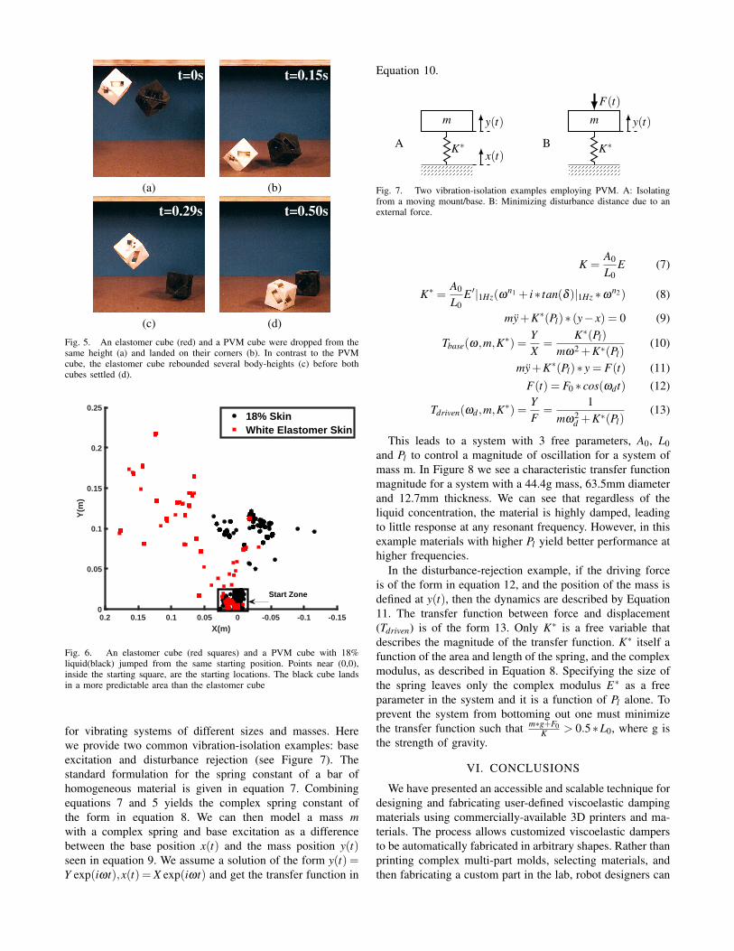
t=0s t=0.15s
(a) (b)
t=0.29s t=0.50s
(c) (d)Fig. 5. An elastomer cube (red) and a PVM cube were dropped from thesame height (a) and landed on their corners (b). In contrast to the PVMcube, the elastomer cube rebounded several body-heights (c) before bothcubes settled (d).
-0.15-0.1-0.0500.050.10.150.2X(m)
0
0.05
0.1
0.15
0.2
0.25
Y(m
)
18% SkinWhite Elastomer Skin
Start Zone
Fig. 6. An elastomer cube (red squares) and a PVM cube with 18%liquid(black) jumped from the same starting position. Points near (0,0),inside the starting square, are the starting locations. The black cube landsin a more predictable area than the elastomer cube
for vibrating systems of different sizes and masses. Herewe provide two common vibration-isolation examples: baseexcitation and disturbance rejection (see Figure 7). Thestandard formulation for the spring constant of a bar ofhomogeneous material is given in equation 7. Combiningequations 7 and 5 yields the complex spring constant ofthe form in equation 8. We can then model a mass mwith a complex spring and base excitation as a differencebetween the base position x(t) and the mass position y(t)seen in equation 9. We assume a solution of the form y(t) =Y exp(iωt),x(t) = X exp(iωt) and get the transfer function in
Equation 10.
m
Ax(t)
K∗
y(t) m
B K∗
F(t)
y(t)
Fig. 7. Two vibration-isolation examples employing PVM. A: Isolatingfrom a moving mount/base. B: Minimizing disturbance distance due to anexternal force.
K =A0
L0E (7)
K∗ =A0
L0E ′|1Hz(ω
n1 + i∗ tan(δ )|1Hz ∗ωn2) (8)
my+K∗(Pl)∗ (y− x) = 0 (9)
Tbase(ω,m,K∗) =YX
=K∗(Pl)
mω2 +K∗(Pl)(10)
my+K∗(Pl)∗ y = F(t) (11)F(t) = F0 ∗ cos(ωdt) (12)
Tdriven(ωd ,m,K∗) =YF
=1
mω2d +K∗(Pl)
(13)
This leads to a system with 3 free parameters, A0, L0and Pl to control a magnitude of oscillation for a system ofmass m. In Figure 8 we see a characteristic transfer functionmagnitude for a system with a 44.4g mass, 63.5mm diameterand 12.7mm thickness. We can see that regardless of theliquid concentration, the material is highly damped, leadingto little response at any resonant frequency. However, in thisexample materials with higher Pl yield better performance athigher frequencies.
In the disturbance-rejection example, if the driving forceis of the form in equation 12, and the position of the mass isdefined at y(t), then the dynamics are described by Equation11. The transfer function between force and displacement(Tdriven) is of the form 13. Only K∗ is a free variable thatdescribes the magnitude of the transfer function. K∗ itself afunction of the area and length of the spring, and the complexmodulus, as described in Equation 8. Specifying the size ofthe spring leaves only the complex modulus E∗ as a freeparameter in the system and it is a function of Pl alone. Toprevent the system from bottoming out one must minimizethe transfer function such that m∗g+F0
K > 0.5∗L0, where g isthe strength of gravity.
VI. CONCLUSIONS
We have presented an accessible and scalable technique fordesigning and fabricating user-defined viscoelastic dampingmaterials using commercially-available 3D printers and ma-terials. The process allows customized viscoelastic dampersto be automatically fabricated in arbitrary shapes. Rather thanprinting complex multi-part molds, selecting materials, andthen fabricating a custom part in the lab, robot designers can

100 101 102 103
!
10-3
10-2
10-1
100
101|T
|T vs !
0 percent5 percent10 percent15 percent20 percent25 percent30 percent35 percent40 percent45 percent50 percent
Fig. 8. The transfer function magnitude can be controlled by varying thepercent liquid concentration of the material
now optimize the material properties and directly 3D printtheir custom soft damper parts.
Our model of the material allows designers to determinethe correct liquid concentration for the desired E ′ and E ′′
properties and frequency response of the material. By takinginto account the working space, the spring constant can beoptimized to reduce the impact force and recoil. For vibratingsystems, the transfer function of the mass-spring systemcan be minimized against the frequency range, maximumdisplacements and mass.
There are many potential applications in the roboticscommunity. For example, this technique could make itpossible to design grippers with printable PVM layers thatminimize the transmitted vibrations from the end-effector tothe arm, reducing actuator wear and control effort to maintainposition. Customized impact protecting skins/pads based onPVMs could allow robots to be more resilient to impacts,to be more accurate when landing, and to reduce controllercomplexity and effort. The vibration damping properties ofPVMs can be used in traditional hard robotics to protectsensitive parts such as cameras and electronics from thevibrations of motors, generators and movement. In the futurethis material and process may find applications in a widerange of fields, including custom sporting gear, personalprotective equipment, and vibration isolation in cameras orindustrial equipment.
ACKNOWLEDGMENT
The authors would like to thank Dr. Abigail Lytton-Jean ofthe Peterson Nanotechnology Materials Facility in the KochInstitute at MIT for supporting data collection efforts.
REFERENCES
[1] S. Li, R. Katzschmann, and D. Rus, “A soft cube capable of control-lable continuous jumping,” in Intelligent Robots and Systems (IROS),2015 IEEE/RSJ International Conference on. IEEE, 2015, pp. 1712–1717.
[2] SandFlea spec sheet, Boston Dynamics. [Online]. Available: http://www.bostondynamics.com/img/SandFlea%20Datasheet%20v1 0.pdf
[3] R. Niiyama, A. Nagakubo, and Y. Kuniyoshi, “Mowgli: A bipedaljumping and landing robot with an artificial musculoskeletal system,”in Proc. IEEE Int. Conf. on Robotics and Automation (ICRA 2007),Roma, Italy, April 2007, pp. 2546–2551 (ThC5.2).
[4] R. Armour, K. Paskins, A. Bowyer, J. Vincent, and W. Megill,“Jumping robots: a biomimetic solution to locomotion across roughterrain,” Bioinspiration & biomimetics, vol. 2, no. 3, p. S65, 2007.
[5] R. V. Martinez, A. C. Glavan, C. Keplinger, A. I. Oyetibo, and G. M.Whitesides, “Soft actuators and robots that are resistant to mechanicaldamage,” Advanced Functional Materials, vol. 24, no. 20, pp. 3003–3010, 2014.
[6] M. T. Tolley, R. F. Shepherd, M. Karpelson, N. W. Bartlett, K. C.Galloway, M. Wehner, R. Nunes, G. M. Whitesides, and R. J. Wood,“An untethered jumping soft robot,” in Intelligent Robots and Systems(IROS 2014), 2014 IEEE/RSJ International Conference on. IEEE,2014, pp. 561–566.
[7] B. M. Yamauchi, “Packbot: a versatile platform for military robotics,”in Defense and Security. International Society for Optics andPhotonics, 2004, pp. 228–237.
[8] J. Paulos, A. Argondizza, and E. Garcia, “Reduced weight hydraulicactuation for small mobile applications,” in 50th AIAA AerospaceSciences Meeting including the New Horizons Forum and AerospaceExposition, 2012, p. 137.
[9] A. D. Marchese, C. D. Onal, and D. Rus, “Autonomous soft roboticfish capable of escape maneuvers using fluidic elastomer actuators,”Soft Robotics, vol. 1, no. 1, pp. 75–87, 2014.
[10] C. Stergiopulos, D. Vogt, M. T. Tolley, M. Wehner, J. Barber, G. M.Whitesides, and R. J. Wood, “A soft combustion-driven pump forsoft robots,” in ASME 2014 Conference on Smart Materials, AdaptiveStructures and Intelligent Systems. American Society of MechanicalEngineers, 2014, pp. V002T04A011–V002T04A011.
[11] M. Raibert, K. Blankespoor, G. Nelson, R. Playter et al., “Bigdog,the rough-terrain quadruped robot,” in Proceedings of the 17th WorldCongress, International Federation of Automatic Control, 2008, pp.10 823–10 825.
[12] B. Samali and K. Kwok, “Use of viscoelastic dampers in reducingwind-and earthquake-induced motion of building structures,” Engi-neering Structures, vol. 17, no. 9, pp. 639–654, 1995.
[13] D. Karnopp, “Active damping in road vehicle suspension systems,”Vehicle System Dynamics, vol. 12, no. 6, pp. 291–311, 1983.
[14] K. B. Shimoga and A. A. Goldenberg, “Soft robotic fingertips part i:A comparison of construction materials,” The International Journal ofRobotics Research, vol. 15, no. 4, pp. 320–334, 1996.
[15] E. I. Rivin, E. I. Rivin, and E. I. Rivin, Passive vibration isolation.Asme press New York, 2003.
[16] D. Lee and D. P. Taylor, “Viscous damper development and futuretrends,” The Structural Design of Tall Buildings, vol. 10, no. 5, pp.311–320, 2001.
[17] J. C. Snowdon, “Vibration isolation: use and characterization,” RubberChemistry and Technology, vol. 53, no. 5, pp. 1041–1087, 1980.
[18] R. MacCurdy, R. Katzschmann, Y. Kim, and D. Rus, “Printable hy-draulics: A method for fabricating robots by 3d co-printing solids andliquids,” in Robotics and Automation (ICRA), 2016 IEEE InternationalConference on. IEEE, 2016.
[19] I. Argatov, “Mathematical modeling of linear viscoelastic impact:Application to drop impact testing of articular cartilage,” TribologyInternational, vol. 63, pp. 213–225, 2013.
[20] F. Varga, M. Drzik, M. Handl, J. Chlpik, P. Kos, E. Filova, M. Rampi-chova, A. Necas, T. Trc, and E. Amler, “Biomechanical character-ization of cartilages by a novel approach of blunt impact testing,”Physiological research, vol. 56, p. S61, 2007.
[21] D. T. Chen, Q. Wen, P. A. Janmey, J. C. Crocker, and A. G. Yodh,“Rheology of soft materials,” Condensed Matter Physics, vol. 1, 2010.