printability and properties of conductive inks on primer...
TRANSCRIPT

Research ArticlePrintability and Properties of Conductive Inks onPrimer-Coated Surfaces
Hector R. Mendez-Rossal and Gernot M. Wallner
Institute of Polymeric Materials and Testing, Johannes Kepler University Linz, Linz 4040, Austria
Correspondence should be addressed to Gernot M. Wallner; [email protected]
Received 26 November 2018; Revised 3 February 2019; Accepted 13 February 2019; Published 7 March 2019
Academic Editor: Gianluca M. Farinola
Copyright © 2019 Hector R. Mendez-Rossal and Gernot M. Wallner. This is an open access article distributed under the CreativeCommons Attribution License, which permits unrestricted use, distribution, and reproduction in any medium, provided theoriginal work is properly cited.
Conductive inks’ performance is affected by the printing conditions and the substrate’s properties. In this study, one graphite-, onepolymer-, and two silver-based conductive inks were printed on four primer-coated metal substrates by screen printing. Thecompatibility and wettability between the inks and the primers were evaluated by infrared spectroscopy and surface energymeasurements. The printed structures were characterized by laser confocal microscopy, peel-off tape testing, and four-pointprobe electrical resistivity testing. In general, silver inks exhibited the best performance in terms of printability and electricalconductivity. The graphite ink presented the worst printing, adhesion, and functional properties. The polymer-based inkrevealed poor wettability but good adhesion and functionality. The surface roughness, energy, and polarity of the primer coatinghad no significant influence on the electrical conductivity of the printed inks.
1. Introduction
Conductive inks are mainly used in the printed electronicsindustry to produce printed circuits, organic light-emittingdiodes, radio-frequency identification tags, and battery teststripes [1–5]. The main advantages of such products are theirflexibility, lightweight design, and lower costs [6]. Conduc-tive inks are based on complex formulations with differentcomponents. The most important is the conductive compo-nent, which may be based onmetal or carbon particles as wellas conductive polymers. Resins are used to disperse the con-ductive particles and provide the mechanical and adhesiveproperties. Solvents are added to dissolve the resins and tocontrol the rheological properties of the ink, and additivesare used to adjust the processability or the functional proper-ties [7–10].
Specific challenges in printing conductive inks areachieving continuous and uniform ink deposition andachieving compatibility of the ink to various substrates, bothof which have a significant impact on electrical conductivityand other functional properties. Printability is dependenton the ink formulation, content, particle size distribution,and shape of the conductive filler, as well as the surface
tension and energy of both ink and substrate. Besides theprinting conditions, including the drying/curing process,the substrate’s properties such as permeability, surfaceroughness, porosity, or surface energy also affect the qualityof the printed structures [7, 8].
Conductive inks have been processed by screen printing,gravure printing, flexography, or inkjet printing [2, 7, 11, 12].Previous research focused on analysing the conductive inks’performance on substrates, such as paper, glass, and poly-mer films [2, 11–14]. So far, the printability and functionalproperties of conductive inks on anticorrosive primer coat-ings have not yet been investigated. Hence, the main objec-tive of this study is to evaluate the printability and propertiesof various conductive inks on selected primer coatings forpotential use in the printed electronics industry. Further-more, potential correlations between the structure of thesubstrate and the functional properties of the printed inksshould be evaluated.
2. Materials and Methods
Four commercially available conductive inks based on silver(two different suppliers), graphite, and PEDOT : PSS were
HindawiInternational Journal of Polymer ScienceVolume 2019, Article ID 3874181, 8 pageshttps://doi.org/10.1155/2019/3874181
selected (see Table 1). Graphite and silver inks are paste-likesolvent inks. The silver ink formulations presented the high-est conductive particle fraction of between 60 and 70%. Thepolymer ink was a gelatinous water-based ink with a rela-tively low amount of PEDOT : PSS polymer. Accordingly,the sheet resistance was higher for the polymer ink comparedto the silver inks.
The substrates were primer-coated 0.5mm metalsheets. The primers are anticorrosive coatings which alsoimprove the printability of the inks. These were appliedby wire-wound rods on the metal substrates and were differ-entiated by the type of binder and content of fillers (silicaparticles as roughness modifiers) in their formulations. Thecoating thicknesses varied from 9 to 16μm. Due to the silicaroughness modifiers with particle diameters of around 5μm,the thickness of the layer was higher for the rough primers. Inagreement with the gloss values ranging from 5 to 84%, theroot mean square roughness was about 0.6μm for the scatter-ing primer coatings Pr_1m and Pr_2m and 0.07μm for thespecular primers Pr_3s and Pr_4s (see Table 2).
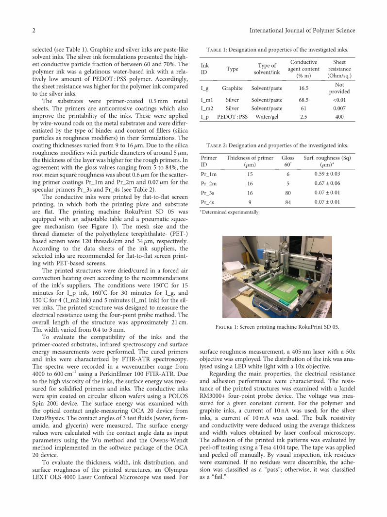
The conductive inks were printed by flat-to-flat screenprinting, in which both the printing plate and substrateare flat. The printing machine RokuPrint SD 05 wasequipped with an adjustable table and a pneumatic squee-gee mechanism (see Figure 1). The mesh size and thethread diameter of the polyethylene terephthalate- (PET-)based screen were 120 threads/cm and 34μm, respectively.According to the data sheets of the ink suppliers, theselected inks are recommended for flat-to-flat screen print-ing with PET-based screens.
The printed structures were dried/cured in a forced airconvection heating oven according to the recommendationsof the ink’s suppliers. The conditions were 150°C for 15minutes for I_p ink, 160°C for 30 minutes for I_g, and150°C for 4 (I_m2 ink) and 5 minutes (I_m1 ink) for the sil-ver inks. The printed structure was designed to measure theelectrical resistance using the four-point probe method. Theoverall length of the structure was approximately 21 cm.The width varied from 0.4 to 3mm.
To evaluate the compatibility of the inks and theprimer-coated substrates, infrared spectroscopy and surfaceenergy measurements were performed. The cured primersand inks were characterized by FTIR-ATR spectroscopy.The spectra were recorded in a wavenumber range from4000 to 600 cm-1 using a PerkinElmer 100 FTIR-ATR. Dueto the high viscosity of the inks, the surface energy was mea-sured for solidified primers and inks. The conductive inkswere spin coated on circular silicon wafers using a POLOSSpin 200i device. The surface energy was examined withthe optical contact angle-measuring OCA 20 device fromDataPhysics. The contact angles of 3 test fluids (water, form-amide, and glycerin) were measured. The surface energyvalues were calculated with the contact angle data as inputparameters using the Wu method and the Owens-Wendtmethod implemented in the software package of the OCA20 device.
To evaluate the thickness, width, ink distribution, andsurface roughness of the printed structures, an OlympusLEXT OLS 4000 Laser Confocal Microscope was used. For
surface roughness measurement, a 405 nm laser with a 50xobjective was employed. The distribution of the ink was ana-lysed using a LED white light with a 10x objective.
Regarding the main properties, the electrical resistanceand adhesion performance were characterized. The resis-tance of the printed structures was examined with a JandelRM3000+ four-point probe device. The voltage was mea-sured for a given constant current. For the polymer andgraphite inks, a current of 10nA was used; for the silverinks, a current of 10mA was used. The bulk resistivityand conductivity were deduced using the average thicknessand width values obtained by laser confocal microscopy.The adhesion of the printed ink patterns was evaluated bypeel-off testing using a Tesa 4104 tape. The tape was appliedand peeled off manually. By visual inspection, ink residueswere examined. If no residues were discernible, the adhe-sion was classified as a “pass”; otherwise, it was classifiedas a “fail.”
Table 1: Designation and properties of the investigated inks.
InkID
TypeType of
solvent/ink
Conductiveagent content
(% m)
Sheetresistance(Ohm/sq.)
I_g Graphite Solvent/paste 16.5Not
provided
I_m1 Silver Solvent/paste 68.5 <0.01I_m2 Silver Solvent/paste 61 0.007
I_p PEDOT : PSS Water/gel 2.5 400
Table 2: Designation and properties of the investigated inks.
PrimerID
Thickness of primer(μm)
Gloss60°
Surf. roughness (Sq)(μm)∗
Pr_1m 15 6 0 59 ± 0 03Pr_2m 16 5 0 67 ± 0 06Pr_3s 16 80 0 07 ± 0 01Pr_4s 9 84 0 07 ± 0 01∗Determined experimentally.
Figure 1: Screen printing machine RokuPrint SD 05.
2 International Journal of Polymer Science

3. Results and Discussion
3.1. Chemical Structure and Surface Energy of Inks andPrimer-Coated Substrates. Characteristic IR bands identifiedin the primers’ and conductive inks’ transmission spectraare summarized in Table 3. Aliphatic (-CH2), carbonyl(-C=O), and ester (-C(=O)O-) bands were found in all theprimers and inks. Except for the polymer-based ink, theprimers and other inks exhibited characteristic bandsrelated to polyester resins. The aliphatic H-C stretchingvibration bands were distinguished at 2950 and 2850 cm-1.For the majority of the samples, a strong band attributedto a carbonyl in the ester groups was distinguished at1720 cm-1. Medium intensity bands were obtained for aro-matic ring stretching at 1600 cm-1 and out-of-plane bendingat between 900 and 670 cm-1. Ester and ether group bandsat 1260-1150 cm-1 and 1125-1020 cm-1, respectively, werefound in all of the samples [15, 16].
The identified amine (-CN and -NH) and isocyanate(N=C=O) bands were the second characteristic of the spec-tra. At 2270-2250 cm-1, bands related to the asymmetricstretch of the isocyanate group were detected [17]. Further-more, stretching carbonyl bands in a urethane group werefound at 1690 cm-1. Also, peaks at 1550-1500 cm-1 wereattributed to the bending of secondary amine groups [16,18]. The primers Pr_2m and Pr_3s revealed weak peaks inthe three mentioned wavenumber regions. For Pr_1m, thesecondary amine peaks were not discernible. Pr_4s and I_gpresented peaks just in the amino region. Both silver inks,I_m1 and I_m2, exhibited a weak isocyanate peak but dif-fered in the secondary amine band, which was perceived justfor I_m2. Presumably, polyisocyanates were used as thecrosslinking agent for the polyester-based inks and residuesof the crosslinking agent were found for the silver inks [19].
All primers and binders from the conductive inks, exceptI_p, were polyester and polyurethane based, maybe as ablended resin system or as polyesterurethanes. These bindersare commonly used for coatings applied on metal substratesand for metallic conductive inks [17, 20]. Due to the chemicalnature, a good compatibility between the primers and thesolvent-based inks was expected.
For the polymer-based ink, the obtained spectrum didnot present a good resolution. However, some bands in thehydroxyl group region at 3500-3300 cm-1 and in the aliphaticH-C stretching vibration range at 2900 cm-1 were identified.Some weak peaks were observed at 1380, 1270, 1120, and1030 cm-1. These peaks were attributed to the aromatic andether groups from PEDOT : PSS, and those at 1180 and1020 cm-1 were attributed to the sulfonate group in PSS[21]. The chemical nature of the polymer-based ink differedsignificantly from the investigated primer systems. Hence,the compatibility may be critical.
In Figure 2, the surface energy and polarity (evaluatedusing the Wu method) of the primers and the conductiveinks as solid layers are depicted. The surface energies ofthe primers ranged between 22 and 28mN/m with low stan-dard deviation, while the surface polarities varied between33 and 43%. Both primers with a smoother surface, Pr_3sand Pr_4s, exhibited lower surface energy and polarity
values. Compared to the IR spectra, this is in agreement withthe weak polar group absorption peaks of these primers.
The surface energy of the inks was slightly higher forI_g, I_m1, and I_m2 and significantly higher for I_p com-pared to that of the primers. The I_g and both silver inksrevealed a surface energy of about 30mN/m. In contrast,the value for the water-based I_p ink was 46mN/m. This isin agreement with findings in the literature [9]. In terms ofsurface polarity, significant differences with values between19 and 69% were determined. I_p showed the highest valuewhich can also be attributed to the water-based formulation.I_m1 was characterized by the lowest polarity percentage.Using the Owens-Wendt method, similar trends wereobtained. In general, the surface energy and especially thesurface polarity values were lower if evaluated by theOwens-Wendt method (except for the surface polarity ofthe water-based polymer ink I_p).
It was observed that all primers had lower surface ener-gies than the inks, which could represent bad wettability[9]. By comparing the primers as well as the graphite and sil-ver inks, a low variation of surface energy was exhibited witha coefficient of error below 10%. These materials also hadsurface polarities below 50%. Hence, a good chemical com-patibility was expected. On the contrary, the compatibilityof the I_p ink and the primers should be lower due to thehigher significant differences in surface energy and polarity.
3.2. Dimensional and Topographical Features of PrintedStructures. In Table 4, the morphological and surface proper-ties of the printed structures are depicted and summarized.The light microscopic images of the lines indicate a patternstructure for the I_g and I_p inks. This was attributed tothe screen grid of the printing process. I_p also showed lim-ited wettability. The amount of voids and nonwetted areaswere quantified between 9 and 25%. In contrast, a uniformand homogeneous print quality was obtained for thesilver-based inks I_m1 and I_m2. The edges of the lines werejagged for the particle-based inks. The quality of the edgeimproved with increasing line width. The best edge definitionwas obtained for the I_p ink, which had few width variations.
Regarding the thickness of the lines, average values ofabout 4.5μm were obtained for the I_g and I_m1 inks. Thethickness variations were lower for I_m1, which did notreveal a pattern morphology. Interestingly, a lower thicknessof 3μmwith a deviation of about 10% was determined for theI_m2 ink. The thickness of the I_p printed structures wasdetected to approximately 400nm, with significant devia-tions. The low accuracy is also attributable to the measure-ment uncertainties of the laser confocal microscope. All thethickness values were independent of the structure’s widthand the topography of the primer coating. This is in contrastto information in the literature where a significant impact ofthe substrate’s surface on the ink transfer and printability wasdescribed, specifically for substrates with roughness values upto the millimeter range. In this study, the average surfaceroughness of the investigated primer coatings was below1μm. These results were in agreement with previous data,where the applicability of conductive inks on surfaces withroughness values below 1μm was evaluated [22].
3International Journal of Polymer Science

Table 3: Identified FTIR bands of the commercial primers and conductive inks.
Functional group (wavenumber)Intensity
Pr_1m Pr_2m Pr_3s Pr_4s I_g I_m1 I_m2 I_p
νb CH2 (3200-2700 cm-1) Weak Weak Meda Med Med Med Med Weak
ν N=C=O (2275-2250 cm-1) Weak Weak Weak — — Weak Weak —
ν C=O (1750-1700 cm-1) Strong Strong Strong Strong Strong Med Strong Weak
ν C=O (urethane) (1690-1680 cm-1) Weak Weak Weak — — — — —
ν Ph (1600 cm-1) Weak Weak Weak Weak Weak Weak Weak —
ν CN and δ NH (1550-1500 cm-1) — Weak Weak Med Med — Med —
ν C(=O)O and δc =CH (1260-1150 cm-1) Strong Strong Strong Strong Weak Weak Med —
ν O-C and δ =CH (1125-1020 cm-1) Weak Weak Med Med Weak Strong Strong Weak
ν Si-O (1100-900 cm-1) Strong Strong — — — — — —
γd Ph (900-670 cm-1) Strong Med Med Med Weak — Weak WeakaMedium intensity. bStretching. cIn-plane deformation. dOut-of-plane deformation.
Surfa
ce en
ergy
(mN
/m)
50
40
30
20
10
0Pr_1m Pr_2m Pr_3s Pr_4s I_g I_m1 I_m2 I_p
InkPrimer
28 28 27
22
3228 31
46
(a)
3338
43 40
31
19
43
69
Surfa
ce p
olar
ity (%
)
80
70
60
50
40
30
20
10
0Pr_1m Pr_2m Pr_3s Pr_4s I_g I_m1 I_m2 I_p
InkPrimer
(b)
Figure 2: Surface energy (a) and surface polarity (b) of primer coatings and conductive inks.
4 International Journal of Polymer Science
The width accuracy for most of the printed linesshowed that the actual value was below the nominal one.This deviation was highest for the I_g ink and the thinnerline with a nominal width of 0.4mm. The width accuracyof the silver-based inks was significantly better and in acomparable range. The best width accuracy was obtainedfor the I_p ink. The differences in the width accuracy werepresumably related to the size of the conductive particles.While the accuracy was worst for the I_g ink with thelargest particles, it was best for the I_p ink without addi-tional particles.
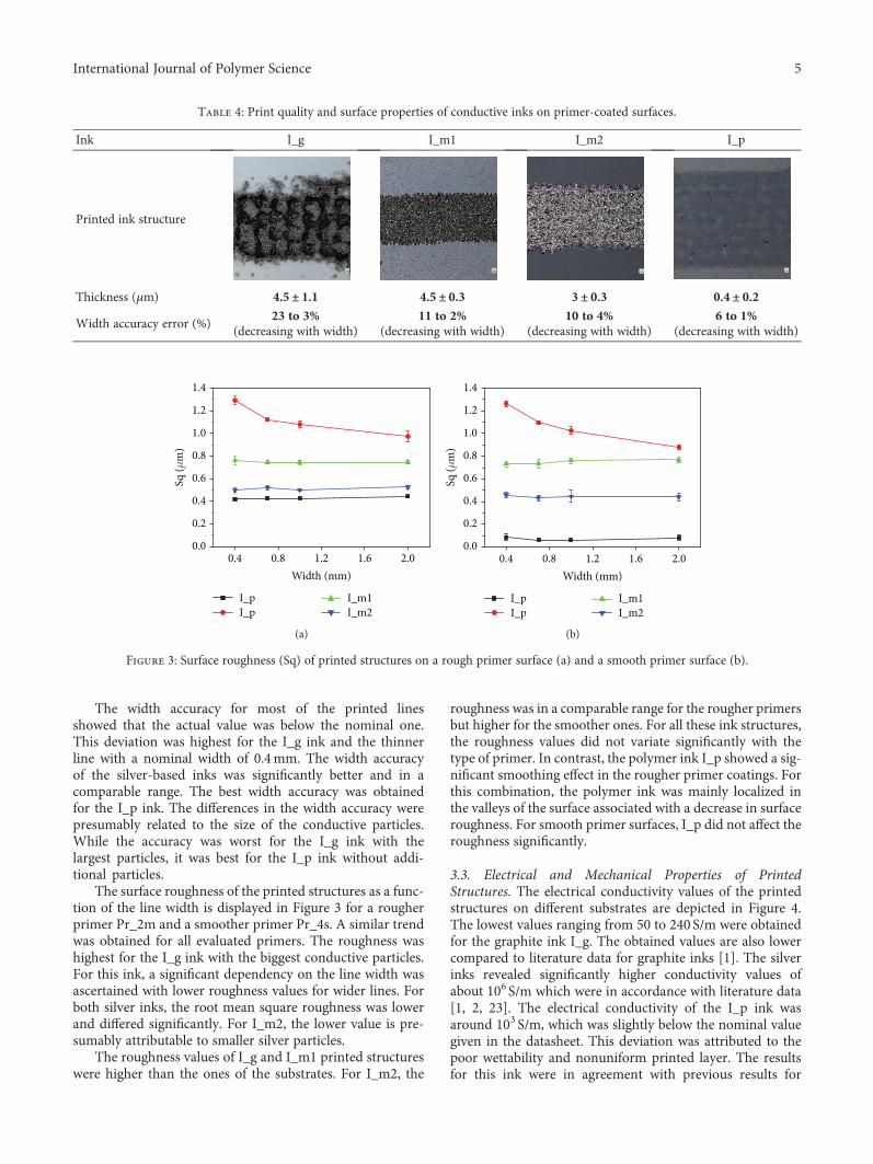
The surface roughness of the printed structures as a func-tion of the line width is displayed in Figure 3 for a rougherprimer Pr_2m and a smoother primer Pr_4s. A similar trendwas obtained for all evaluated primers. The roughness washighest for the I_g ink with the biggest conductive particles.For this ink, a significant dependency on the line width wasascertained with lower roughness values for wider lines. Forboth silver inks, the root mean square roughness was lowerand differed significantly. For I_m2, the lower value is pre-sumably attributable to smaller silver particles.
The roughness values of I_g and I_m1 printed structureswere higher than the ones of the substrates. For I_m2, the
roughness was in a comparable range for the rougher primersbut higher for the smoother ones. For all these ink structures,the roughness values did not variate significantly with thetype of primer. In contrast, the polymer ink I_p showed a sig-nificant smoothing effect in the rougher primer coatings. Forthis combination, the polymer ink was mainly localized inthe valleys of the surface associated with a decrease in surfaceroughness. For smooth primer surfaces, I_p did not affect theroughness significantly.
3.3. Electrical and Mechanical Properties of PrintedStructures. The electrical conductivity values of the printedstructures on different substrates are depicted in Figure 4.The lowest values ranging from 50 to 240 S/m were obtainedfor the graphite ink I_g. The obtained values are also lowercompared to literature data for graphite inks [1]. The silverinks revealed significantly higher conductivity values ofabout 106 S/m which were in accordance with literature data[1, 2, 23]. The electrical conductivity of the I_p ink wasaround 103 S/m, which was slightly below the nominal valuegiven in the datasheet. This deviation was attributed to thepoor wettability and nonuniform printed layer. The resultsfor this ink were in agreement with previous results for
Table 4: Print quality and surface properties of conductive inks on primer-coated surfaces.
Ink I_g I_m1 I_m2 I_p
Printed ink structure
Thickness (μm) 4.5± 1.1 4.5± 0.3 3± 0.3 0.4± 0.2
Width accuracy error (%)23 to 3%
(decreasing with width)11 to 2%
(decreasing with width)10 to 4%
(decreasing with width)6 to 1%
(decreasing with width)
I_pI_p
I_m1I_m2
0.4 0.8 1.2 1.6 2.0Width (mm)
1.4
1.2
1.0
0.8
0.6
0.4
0.2
0.0
Sq (�휇
m)
(a)
I_pI_p
I_m1I_m2
0.4 0.8 1.2 1.6 2.0Width (mm)
1.4
1.2
1.0
0.8
0.6
0.4
0.2
0.0
Sq (�휇
m)
(b)
Figure 3: Surface roughness (Sq) of printed structures on a rough primer surface (a) and a smooth primer surface (b).
5International Journal of Polymer Science

PEDOT : PSS ink formulations containing alcohols and/orsurfactants [24, 25].
The obtained conductivity values were increasing withthe line width. This was more perceived at the lines withwidths of 0.4 and 0.7mm. Such effects were also reportedin literature and were related to the different surface/bulkratio [13]. As to the effect of the primer, the electrical per-formance was dependent on the ink/primer combination.The lowest conductivity values for all printed inks weredetected for the smoother primer Pr_3s. On the contrary,the highest values for I_g and I_m1 inks were also obtainedin combination with a smooth primer Pr_4s. I_m2 achievedthe highest conductivity on the rougher primer Pr_2m andI_p on Pr_1m.
To elucidate the potential effects of the substrates’ surfaceproperties on the electrical conductivity, a one-way ANOVAwas conducted for each conductive ink. It was deduced thatthere were statistically significant differences on the electricalconductivity performance of the inks I_g (F 3, 4 = 31 1,p = 0 003), I_m1 (F 3, 4 = 7 6, p = 0 04), I_m2 (F 3, 4 = 26,p = 0 04), and I_p (F 3, 4 = 458 60, p = 1 6E − 5) at thep < 0 05 level. The LSD-Fisher post hoc test also revealedthat for each ink, a different pair of primers did not havestatistically significant differences. Therefore, no general
tendencies were observed for all the inks, only ink-specificbehaviours. Similar results were previously reported forsilver-based inks, but for a polymer ink a correlation betweenthe conductivity and the surface roughness of the printedstructures was stated [7, 24]. However, in this research, theink-primer combination showed a higher effect on the con-ductivity than the surface properties of the substrate andthe printed structures.
The peel-off test revealed a good adhesion performanceof the printed ink I_m1 and I_p on all substrates (seeTable 5). No residues were detected on the tape. I_m2 passedthe test in all primers except for the smooth primer Pr_4s. It
0.0 0.4 0.8 1.2 1.6 2.0 2.4
Pr_1mPr_2m
Pr_3sPr_4s
Width (mm)
2.4E + 02
2.0E + 02
1.6E + 02
1.2E + 02
8.0E + 01
4.0E + 01
Con
duct
ivity
(S/m
)
I_g
(a)
0.0 0.4 0.8 1.2 1.6 2.0 2.4
Pr_1mPr_2m
Pr_3sPr_4s
Width (mm)
1.1E + 07
1.0E + 07
9.0E + 06
8.0E + 06
7.0E + 06
6.0E + 06
5.0E + 06
Con
duct
ivity
(S/m
)
I_m1
(b)
0.0 0.4 0.8 1.2 1.6 2.0 2.4
Pr_1mPr_2m
Pr_3sPr_4s
Width (mm)
1.1E + 07
1.0E + 07
9.0E + 06
8.0E + 06
7.0E + 06
6.0E + 06
5.0E + 06
Con
duct
ivity
(S/m
)
I_m2
(c)
0.0 0.4 0.8 1.2 1.6 2.0 2.4
Pr_1mPr_2m
Pr_3sPr_4s
Width (mm)
I_p
1.2E + 04
1.1E + 04
1.0E + 04
9.0E + 03
8.0E + 03
7.0E + 03
6.0E + 03
Con
duct
ivity
(S/m
)
(d)
Figure 4: Electrical conductivities of printed structures with different line widths based on graphite (I_g), silver (I_m1 and I_m2), andconjugated polymer (I_p).
Table 5: Qualitative adhesion of conductive inks on primer-coatedsubstrates.
Primer I_g I_m1 I_m2 I_p
Pr_1m Fail∗ Pass Pass Pass
Pr_2m Fail∗ Pass Pass Pass
Pr_3s Fail∗ Pass Pass Pass
Pr_4s Fail∗ Pass Fail+ Pass
Failure mode. ∗Intense ink removal/printed structure not affected.+Delamination of primer from substrate.
6 International Journal of Polymer Science

failed via delamination in the substrate-to-primer interface(see Figure 5). Most likely, the solvent of I_m2 was able topenetrate through the primer layer and weaken the interfaceby an environmental stress cracking mechanism [26]. How-ever, this phenomenon was detected only for this primer/inkcombination.
A poor adhesion performance was attained for the I_gink on all primers investigated. As depicted in Figure 5, a sig-nificant amount of graphite had remained on both the tapeand the primer. For this reason, this ink was characterizedby a cohesive failure mechanism. Such failure types are char-acteristic for graphite-based ink formulations [1].
4. Conclusions
Four commercial conductive inks based on silver, graphite,and PEDOT : PSS were screen printed on differentprimer-coated substrates. A basic characterization of theprimers, inks, and their printed structures was performedto determine their compatibility, printability, and functionalproperties. According to the identified IR bands, all primersand conductive inks, except the polymer-based ink, werebased on polyester and polyurethane resins. Additionally,they exhibited low variations of surface energy values and asimilar surface polarity percentage. Due to the similar chem-ical nature and surface properties, good compatibility wasexpected between graphite, silver inks, and primers. In con-trast, the compatibility of the polymer-based ink was pre-sumed to be lower because of the significant differencesobserved in its properties.
By laser confocal microscopy, the dimensional and topo-graphical features of the printed structures were analysed.Both silver inks presented the best printability propertieswith uniform and continuously deposited ink layers. Graph-ite ink showed an average printability characterized by con-tinuous lines but low uniformity and morphologicalproperties. The worst performer was the polymer ink whichexhibited nonwetted areas ranging from 9 to 25%. However,the polymer ink structures revealed the best width accuracyand edge definition. While the surface roughness of thegraphite and the silver inks’ printed lines were independentfrom the substrates’ properties, a smoothing effect was ascer-tained for the polymer ink on rough primer surfaces.
The highest electrical conductivity was obtained by thesilver inks’ printed lines with values of about 106 S/m. Thegraphite ink structures presented the lowest conductivitywith values ranging from 50 to 240 S/m. The electrical con-ductivity for the printed polymer ink was around 103 S/m.This was attributed to the poor printability on the substrates.No significant correlations between electrical conductivityand the substrate’s surface properties were deduced. Thepeel-off test revealed a good adhesion performance of theprinted polymer and silver inks. The silver ink I_m2 printedon the smooth primer Pr_4s failed the test via delaminationin the substrate-to-primer interface. The graphite ink showeda cohesive failure mechanism with ink residues in both thetape and the primer.
Data Availability
The experimental data used to support the findings of thisstudy are included within the article.
Conflicts of Interest
The authors declare that there is no conflict of interestregarding the publication of this paper.
Acknowledgments
The authors kindly acknowledge the support of the Instituteof Microelectronics and Microsensors at the Johannes KeplerUniversity Linz for providing the devices for screen printing.The publication of this article was supported by the JohannesKepler Open Access Publishing Fund.
References
[1] S. Bhore, “Formulation and evaluation of resistive inks forapplications in printed electronics,” MSc Thesis, WesternMichigan University, USA, 2013.
[2] R. Kattumenu, “Flexography printing of silver based conduc-tive inks on packaging substrates,” PhD Thesis,WesternMich-igan University, USA, 2008.
[3] S. Joshi, “Evaluation of silver/graphite ink blends for use inprinted electronics,” MSc Thesis, Western Michigan Univer-sity, USA, 2011.
(a) (b)
Figure 5: Adhesive failure of I_m2 (a) and cohesive failure of I_g (b).
7International Journal of Polymer Science

[4] M. Cruz, M. Joyce, P. Fleming, M. Rebros, andA. Pekarovicova, “Surface topography contribution to RFIDtag efficiency related to conductivity,” in Coating and GraphicArts Conference, vol. 2, pp. 1290–1326, TAPPI, 2007.
[5] A. Kamyshny, J. Steinke, and S. Magdassi, “Metal-based inkjetinks for printed electronics,” The Open Applied Physics Jour-nal, vol. 4, no. 1, pp. 19–36, 2011.
[6] K. Ghaffarzadeh, Y. Yamamoto, and H. Zervos, “Conductiveink markets 2017–2027: forecasts, technologies, players,” June2017 http://www.idtechex.com/research/reports/conductive-ink-markets-2017-2027-forecasts-technologies-players-000521.asp.
[7] E. Hrehorova, A. Pekarovicova, and P. Fleming, “Gravureprintability of conducting polymer inks,” in Proceedings ofIS&T Digital Fabrication, Denver, USA, 2006.
[8] E. Hrehorova, “Materials and processes for printed electronics:evaluation of gravure printing in electronics manufacture,”PhD Thesis, Western Michigan University, USA, 2007.
[9] J. Izdebska and S. Thomas, “Printing on polymers,” in Printingon Polymers: Theory and Practice, Elsevier B.V., Oxford, UK,2016.
[10] J. Ouyang, C. W. Chu, F. C. Chen, Q. Xu, and Y. Yang,“Polymer optoelectronic devices with high‐conductivitypoly(3,4‐ethylenedioxythiophene) anodes,” Journal of Macro-molecular Science, Part A, vol. 41, no. 12, pp. 1497–1511,2004.
[11] N. Perinka, C. H. Kim, M. Kaplanova, and Y. Bonnassieux,“Preparation and characterization of thin conductive polymerfilms on the base of PEDOT : PSS by ink-jet printing,” PhysicsProcedia, vol. 44, pp. 120–129, 2013.
[12] L. K. Wood, E. Hrehorova, T. W. Joyce et al., “Paper substratesand inks for printed electronics,” in Pira Ink on Paper Sympo-sium, p. 7, Smithers Pira, Surrey, UK, 2005.
[13] M. Borghetti, M. Ghittorelli, E. Sardini, M. Serpelloni, andF. Torricelli, “Electrical characterization of PEDOT : PSS stripsdeposited by inkjet printing on plastic foil for sensormanufacturing,” IEEE Transactions on Instrumentation andMeasurement, vol. 65, no. 9, pp. 2137–2144, 2016.
[14] J. Y. Kim, J. H. Jung, D. E. Lee, and J. Joo, “Enhancement ofelectrical conductivity of poly(3,4-ethylenedioxythiophene)/-poly(4-styrenesulfonate) by a change of solvents,” SyntheticMetals, vol. 126, no. 2-3, pp. 311–316, 2002.
[15] U. Knuutinen and P. Kyllonen, “Two case studies of unsatu-rated polyester composite art objects,” Morana RTD,E-Preservation Science, vol. 3, pp. 11–19, 2006.
[16] G. A. Verleye, N. P. Roeges, and M. O. De Moor, Easy Identi-fication of Plastics and Rubbers, Rapra Technology Limited,UK, 2001.
[17] D. Stoye and W. Freitag, Paints, Coatings and Solvents,Wiley-VCH, GER, 1998.
[18] J. Coates, “Interpretation of infrared spectra, a practicalapproach,” in Encyclopedia of Analytical Chemistry, R. A.Meyers and M. L. McKelvy, Eds., USA, 2014.
[19] Z. W. Wicks Jr, F. N. Jones, S. P. Pappas, and D. A. Wicks,Organic Coatings: Science and Technology, John Wiley andSons, USA, 2007.
[20] K. Gilleo, Polymer Thick Film: Today’s Emerging Technologyfor a Clean Environment Tomorrow, Van Nostrand Reinhold,USA, 2016.
[21] N. G. Yasri, A. K. Sundramoorthy, W. J. Chang, andS. Gunasekaran, “Highly selective mercury detection at
partially oxidized graphene/poly(3,4-ethylenedioxythiophe-ne) : poly(styrenesulfonate) nanocomposite film-modifiedelectrode,” Frontiers in Materials, vol. 1, p. 33, 2014.
[22] Y. Y. Lim, Y. M. Goh, M. Yoshida et al., “Silver screen printedtransmission lines—analyzing the influence of substrateroughness on the RF performance up to 30GHz,” in 2014 IEEE16th Electronics Packaging Technology Conference (EPTC),pp. 22–26, Singapore, December 2014.
[23] A. Karwa, “Printing studies with conductive inks and explora-tion of new conducting polymer compositions,” MSc Thesis,Rochester Institute of Technology, USA, 2006.
[24] E. Hrehorova, M. Rebros, A. Pekarovicova, P. Fleming, andV. Bliznyuk, “Characterization of conductive polymer inksbased on PEDOT : PSS,” TAGA Journal, vol. 4, pp. 219–231,2008.
[25] R. Lubianez, S. Kirchmeyer, and D. Gaiser, Advances in PED-OT : PSS Conductive Polymer Dispersions, H.C. Starck GmbH,GER, 2008.
[26] W. C. Golton, Analysis of Paints and Related Materials:Current Techniques for Solving Coatings Problems, ASTMInternational, Philadelphia, USA, 1992.
8 International Journal of Polymer Science

CorrosionInternational Journal of
Hindawiwww.hindawi.com Volume 2018
Advances in
Materials Science and EngineeringHindawiwww.hindawi.com Volume 2018
Hindawiwww.hindawi.com Volume 2018
Journal of
Chemistry
Analytical ChemistryInternational Journal of
Hindawiwww.hindawi.com Volume 2018
Scienti�caHindawiwww.hindawi.com Volume 2018
Polymer ScienceInternational Journal of
Hindawiwww.hindawi.com Volume 2018
Hindawiwww.hindawi.com Volume 2018
Advances in Condensed Matter Physics
Hindawiwww.hindawi.com Volume 2018
International Journal of
BiomaterialsHindawiwww.hindawi.com
Journal ofEngineeringVolume 2018
Applied ChemistryJournal of
Hindawiwww.hindawi.com Volume 2018
NanotechnologyHindawiwww.hindawi.com Volume 2018
Journal of
Hindawiwww.hindawi.com Volume 2018
High Energy PhysicsAdvances in
Hindawi Publishing Corporation http://www.hindawi.com Volume 2013Hindawiwww.hindawi.com
The Scientific World Journal
Volume 2018
TribologyAdvances in
Hindawiwww.hindawi.com Volume 2018
Hindawiwww.hindawi.com Volume 2018
ChemistryAdvances in
Hindawiwww.hindawi.com Volume 2018
Advances inPhysical Chemistry
Hindawiwww.hindawi.com Volume 2018
BioMed Research InternationalMaterials
Journal of
Hindawiwww.hindawi.com Volume 2018
Na
nom
ate
ria
ls
Hindawiwww.hindawi.com Volume 2018
Journal ofNanomaterials
Submit your manuscripts atwww.hindawi.com