print preview - … · the oceanus-e3 (figure 1-1) is a 440 vac three-phase electric air compressor...
TRANSCRIPT

S6220-EV-MMO-0100910-LP-104-3316
OPERATION AND MAINTENANCE MANUAL WITHILLUSTRATED PARTS BREAKDOWN
ORGANIZATIONAL LEVEL
OCEANUS-E3 COMPRESSORBAUER COMPRESSORS, INC.
DISTRIBUTION STATEMENT A: Approved for public release; distribution is unlimited.
PUBLISHED BY DIRECTION OF COMMANDER, NAVAL SEA SYSTEMS COMMAND
21 OCTOBER 2005


S6220-EV-MMO-010
Insert List of Effective Pages Here.
LIST OF EFFECTIVE PAGES
Date of Original Pages is:
Original............0............21 OCTOBER 2005
Total number of pages in this publication is 68 consisting of the following:
Page No. Change No.* Page No. Change No.*Title/A.................................................... 0 3-1 - 3-5/(3-6 blank)................................ 0Change Record....................................... 0 4-1 - 4-3/(4-4 blank)................................ 0i - iv ....................................................... 0 5-1 - 5-2................................................... 0Foreward-1 - Foreward-3....................... 0 6-1 - 6-14................................................. 0i - ii......................................................... 0 7-1 - 7-14................................................. 01-1 - 1-4.................................................. 0 A-1 - A-4................................................. 02-1 - 2-10................................................ 0

S6220-EV-MMO-010
A

S6220-EV-MMO-010
RECORD OF CHANGES
CHANGE NO.* DATE TITLE OR BRIEFDESCRIPTION
ENTERED BY
* List each advance change notice (ACN) and formal change as received. When an ACN is canceled by a formal change,cross out the ACN.
Change Record-1/(Change Record-2 blank)


S6220-EV-MMO-010
TABLE OF CONTENTS
Chapter Page
LIST OF EFFECTIVE PAGES . . . . . . . . . . . . . . . . . . . . . . . . . . . . . . . . . . .FOREWORD . . . . . . . . . . . . . . . . . . . . . . . . . . . . . . . . . . . . . Foreword-1SAFETY SUMMARY . . . . . . . . . . . . . . . . . . . . . . . . . . . . . . . . . . . . . . i1 INTRODUCTION AND SAFETY PRECAUTIONS . . . . . . . . . . . . . . . . . . . . . 1-1
1.1 INTRODUCTION. . . . . . . . . . . . . . . . . . . . . . . . . . . . . . . . . . . . . 1-11.1.1 Purpose. . . . . . . . . . . . . . . . . . . . . . . . . . . . . . . . . . . . . . . . . 1-11.2 SYSTEM DESCRIPTION. . . . . . . . . . . . . . . . . . . . . . . . . . . . . . . . . 1-11.3 SPECIFICATIONS. . . . . . . . . . . . . . . . . . . . . . . . . . . . . . . . . . . . 1-11.4 SAFETY PRECAUTIONS. . . . . . . . . . . . . . . . . . . . . . . . . . . . . . . . . 1-31.5 EQUIPMENT AND ACCESSORIES SUPPLIED. . . . . . . . . . . . . . . . . . . . . . 1-31.6 REFERENCE PUBLICATIONS NOT SUPPLIED. . . . . . . . . . . . . . . . . . . . . . 1-31.7 RETURNING TO DEPOT. . . . . . . . . . . . . . . . . . . . . . . . . . . . . . . . . 1-4
2 OPERATION . . . . . . . . . . . . . . . . . . . . . . . . . . . . . . . . . . . . . . . 2-12.1 INTRODUCTION. . . . . . . . . . . . . . . . . . . . . . . . . . . . . . . . . . . . . 2-12.2 CONTROLS AND INDICATORS. . . . . . . . . . . . . . . . . . . . . . . . . . . . . 2-12.3 OPERATING PROCEDURES. . . . . . . . . . . . . . . . . . . . . . . . . . . . . . . 2-3
3 FUNCTIONAL DESCRIPTION . . . . . . . . . . . . . . . . . . . . . . . . . . . . . . 3-13.1 INTRODUCTION. . . . . . . . . . . . . . . . . . . . . . . . . . . . . . . . . . . . . 3-13.2 DESCRIPTION. . . . . . . . . . . . . . . . . . . . . . . . . . . . . . . . . . . . . . 3-1
4 SCHEDULED MAINTENANCE . . . . . . . . . . . . . . . . . . . . . . . . . . . . . . 4-14.1 INTRODUCTION. . . . . . . . . . . . . . . . . . . . . . . . . . . . . . . . . . . . . 4-14.2 SCOPE. . . . . . . . . . . . . . . . . . . . . . . . . . . . . . . . . . . . . . . . . . 4-14.3 SAFETY REQUIREMENTS. . . . . . . . . . . . . . . . . . . . . . . . . . . . . . . . 4-14.4 MAINTENANCE CONCEPTS. . . . . . . . . . . . . . . . . . . . . . . . . . . . . . . 4-14.5 PLANNED MAINTENANCE SYSTEM. . . . . . . . . . . . . . . . . . . . . . . . . . 4-24.6 USN MAINTENANCE AND MATERIAL MANAGEMENT (3-M) SYSTEM COVERAGE AND
PROBLEM REPORTING. . . . . . . . . . . . . . . . . . . . . . . . . . . . . . . . . 4-24.7 GENERAL MAINTENANCE INSTRUCTIONS. . . . . . . . . . . . . . . . . . . . . . 4-2
5 TROUBLESHOOTING . . . . . . . . . . . . . . . . . . . . . . . . . . . . . . . . . . 5-15.1 INTRODUCTION. . . . . . . . . . . . . . . . . . . . . . . . . . . . . . . . . . . . . 5-15.2 GENERAL TROUBLESHOOTING INSTRUCTIONS. . . . . . . . . . . . . . . . . . . 5-1
6 CORRECTIVE MAINTENANCE . . . . . . . . . . . . . . . . . . . . . . . . . . . . . 6-16.1 INTRODUCTION. . . . . . . . . . . . . . . . . . . . . . . . . . . . . . . . . . . . . 6-16.2 GENERAL MAINTENANCE INFORMATION. . . . . . . . . . . . . . . . . . . . . . . 6-16.3 TEST EQUIPMENT AND TOOLS. . . . . . . . . . . . . . . . . . . . . . . . . . . . . 6-16.4 MATERIALS. . . . . . . . . . . . . . . . . . . . . . . . . . . . . . . . . . . . . . . 6-2
i
S6220-EV-MMO-010
TABLE OF CONTENTS - CONTINUED6.5 GENERAL MAINTENANCE PROCEDURES. . . . . . . . . . . . . . . . . . . . . . . 6-26.6 CORRECTIVE MAINTENANCE. . . . . . . . . . . . . . . . . . . . . . . . . . . . . 6-2
7 ILLUSTRATED PARTS BREAKDOWN . . . . . . . . . . . . . . . . . . . . . . . . . . 7-17.1 INTRODUCTION. . . . . . . . . . . . . . . . . . . . . . . . . . . . . . . . . . . . . 7-17.2 PARTS LISTS AND ILLUSTRATIONS. . . . . . . . . . . . . . . . . . . . . . . . . . 7-17.3 LIST OF MANUFACTURERS . . . . . . . . . . . . . . . . . . . . . . . . . . . . . 7-14
Appendix A OPERATIONAL CHECKLIST . . . . . . . . . . . . . . . . . . . . . . . . . A-1A.1 INTRODUCTION. . . . . . . . . . . . . . . . . . . . . . . . . . . . . . . . . . . . A-1A.2 CHECKLIST PROVIDED. . . . . . . . . . . . . . . . . . . . . . . . . . . . . . . . A-1
ii
S6220-EV-MMO-010
LIST OF ILLUSTRATIONS
Number Title Page
1-1 Oceanus-E3. . . . . . . . . . . . . . . . . . . . . . . . . . . . . . . . . . . . . . . 1-32-1 Oceanus-E3 Controls and Indicators. . . . . . . . . . . . . . . . . . . . . . . . . . . 2-22-2 Fill Hose Assembly Controls and Indicator. . . . . . . . . . . . . . . . . . . . . . . . 2-32-3 Check CO and Moisture Indicator. . . . . . . . . . . . . . . . . . . . . . . . . . . . 2-42-4 Dipstick Indents. . . . . . . . . . . . . . . . . . . . . . . . . . . . . . . . . . . . . 2-52-5 Compressor Valves. . . . . . . . . . . . . . . . . . . . . . . . . . . . . . . . . . . 2-62-6 Fill Hose Assembly Attached to SCBA Assembly. . . . . . . . . . . . . . . . . . . . . 2-72-7 Compressor Shut Down. . . . . . . . . . . . . . . . . . . . . . . . . . . . . . . . . 2-82-8 Fill Hose Assembly. . . . . . . . . . . . . . . . . . . . . . . . . . . . . . . . . . . 2-92-9 Fill Hose Assembly Stowage Position. . . . . . . . . . . . . . . . . . . . . . . . . . 2-103-1 Compressor Block without Front Shroud. . . . . . . . . . . . . . . . . . . . . . . . . 3-13-2 P0 Filter System. . . . . . . . . . . . . . . . . . . . . . . . . . . . . . . . . . . . . 3-23-3 CO and Moisture Indicator. . . . . . . . . . . . . . . . . . . . . . . . . . . . . . . . 3-33-4 Fill Hose Assembly. . . . . . . . . . . . . . . . . . . . . . . . . . . . . . . . . . . 3-43-5 Electric Motor. . . . . . . . . . . . . . . . . . . . . . . . . . . . . . . . . . . . . . 3-43-6 Compressor Frame. . . . . . . . . . . . . . . . . . . . . . . . . . . . . . . . . . . 3-56-1 Compressor Frame Removal. . . . . . . . . . . . . . . . . . . . . . . . . . . . . . . 6-36-2 Front and Rear Shroud Removal. . . . . . . . . . . . . . . . . . . . . . . . . . . . . 6-46-3 Loosening Bolts on Electric Motor. . . . . . . . . . . . . . . . . . . . . . . . . . . . 6-66-4 Approximate V-Belt Deflection. . . . . . . . . . . . . . . . . . . . . . . . . . . . . . 6-66-5 Proper Pulley Alignment. . . . . . . . . . . . . . . . . . . . . . . . . . . . . . . . . 6-76-6 1st Stage Safety Valve. . . . . . . . . . . . . . . . . . . . . . . . . . . . . . . . . 6-106-7 2nd Stage Safety Valve. . . . . . . . . . . . . . . . . . . . . . . . . . . . . . . . 6-116-8 Final Pressure Safety Valve Assembly. . . . . . . . . . . . . . . . . . . . . . . . . 6-126-9 Fill Hose Connected to Check Valve. . . . . . . . . . . . . . . . . . . . . . . . . . 6-137-1 Compressor Frame Parts. . . . . . . . . . . . . . . . . . . . . . . . . . . . . . . . . 7-27-2 Front and Rear Shroud Parts. . . . . . . . . . . . . . . . . . . . . . . . . . . . . . . 7-47-3 Electric Motor and Pulley Parts. . . . . . . . . . . . . . . . . . . . . . . . . . . . . . 7-67-4 Air Intake and Safety Valves Parts. . . . . . . . . . . . . . . . . . . . . . . . . . . . 7-87-5 Filter Assembly Parts. . . . . . . . . . . . . . . . . . . . . . . . . . . . . . . . . 7-107-6 Fill Hose Assembly Parts. . . . . . . . . . . . . . . . . . . . . . . . . . . . . . . 7-12
iii

S6220-EV-MMO-010
LIST OF TABLES
Number Title Page
1-1 Oceanus-E3 Specifications. . . . . . . . . . . . . . . . . . . . . . . . . . . . . . . . 1-21-2 Equipment and Accessories Supplied. . . . . . . . . . . . . . . . . . . . . . . . . . . 1-31-3 Reference Publications Not Supplied. . . . . . . . . . . . . . . . . . . . . . . . . . . 1-42-1 Oceanus-E3 Controls and Indicators. . . . . . . . . . . . . . . . . . . . . . . . . . . 2-12-2 Fill Hose Assembly Controls and Indicator. . . . . . . . . . . . . . . . . . . . . . . . 2-35-1 Troubleshooting Guidelines. . . . . . . . . . . . . . . . . . . . . . . . . . . . . . . 5-16-1 Tools Required. . . . . . . . . . . . . . . . . . . . . . . . . . . . . . . . . . . . . 6-17-1 Compressor Frame Parts List. . . . . . . . . . . . . . . . . . . . . . . . . . . . . . . 7-37-2 Front and Rear Shroud Parts List. . . . . . . . . . . . . . . . . . . . . . . . . . . . . 7-57-3 Electric Motor and Pulley Parts List. . . . . . . . . . . . . . . . . . . . . . . . . . . 7-77-4 Air Intake and Safety Valves Parts List. . . . . . . . . . . . . . . . . . . . . . . . . . 7-97-5 Filter Assembly Parts List. . . . . . . . . . . . . . . . . . . . . . . . . . . . . . . 7-117-6 Fill Hose Assembly Parts List. . . . . . . . . . . . . . . . . . . . . . . . . . . . . 7-137-7 List of Manufacturers. . . . . . . . . . . . . . . . . . . . . . . . . . . . . . . . . 7-14A-1 Operational Use Checklist. . . . . . . . . . . . . . . . . . . . . . . . . . . . . . . A-1
iv

S6220-EV-MMO-010
FOREWORD
This technical manual contains procedures for operation and maintenance of the Oceanus-E3. Theinformation in this manual is presented in seven chapters and one appendix, as follows:
• Chapter 1 - Introduction and Safety Precautions• Chapter 2 - Operation• Chapter 3 - Functional Description• Chapter 4 - Scheduled Maintenance• Chapter 5 - Troubleshooting• Chapter 6 - Corrective Maintenance• Chapter 7 - Illustrated Parts Breakdown• Appendix A - Operational Checklist.
Ships, training activities, supply points, depots, Naval Shipyards and Supervisors of Shipbuilding arerequested to arrange for the maximum practical use and evaluation of NAVSEA technical manuals.Reporting of errors, omissions, inconsistencies, and suggestions for improving this manual is encouraged,using NAVSEA Technical Manual Deficiency/Evaluation Report (TMDER). Submit TMDER via theNaval Systems Data Support Activity web site at http://nsdsa.phdnswc.navy.mil/tmder/tmder.asp. Allfeedback comments will be thoroughly investigated and originators will be advised of resulting action.Should the need arise, the In-Service Engineering Agent (ISEA) may be contacted at CommandingOfficer, Naval Surface Warfare Center Panama City, Attn: Code S14, 110 Vernon Avenue, Panama City,FL 32407-7001. The Damage Control Web site is another reference tool the ISEA provides for DamageControl personnel. This Web site provides Navy messages, tips, technical manuals, and other helpfulinformation on Damage Control equipment and can be accessed at http://www.dcfp.navy.mil.Distribution of this manual and subsequent changes are automatic to all authorized users. Additionalcopies are available from the U. S. Army Media Distribution Center, 1655 Woodson Road, St. Louis MO63114-6128. To change the number of copies authorized on automatic distribution, address request to:Commanding Officer, Attn: Code A15 Bldg 79, Naval Surface Warfare Center, Panama City, 110 VernonAvenue, Panama City, FL 32407-7001.
Foreword-1
S6220-EV-MMO-010
ABBREVIATIONS AND ACRONYMS3-M Maintenance and Material Management
CAGE Commercial and Government EntityCCW CounterclockwiseCGA Compressed Gas AssociationCO Carbon MonoxideCOSAL Coordinated Shipboard Allowance ListCW Clockwise
dB Decibel
FEDLOG Federal Logistics Record
HP HorsepowerHz Hertz
IAW In Accordance WithIPB Illustrated Parts BreakdownISEA In-Service Engineering Agent
MDS Maintenance Data Systemmg/m³ Milligrams Per Cubic MeterMIL-STD Military StandardMIP Maintenance Index PageMRC Maintenance Requirement Card
NAVOSH Navy Occupational Safety and HealthNAVSEA Naval Sea Systems Command
OPNAV Office of the Chief of Naval OperationsOPNAVINST Office of the Chief of Naval Operations Instruction
PMS Planned Maintenance SystemPART NO. Part NumberPSI Pound Per Square Inch
Foreword-2

S6220-EV-MMO-010
QTY Quantity
RA Return AuthorizationRPM Revolutions Per Minute
SCBA Self-Contained Breathing ApparatusSCF Standard Cubic FeetSCFM Standard Cubic Feet Per MinuteSPMIG Standard PMS Materials Identification Guide
TMDER Technical Manual Deficiency/Evaluation Report
USN United States Navy
VAC Volts Alternating Current
Foreword-3/(Foreword-4 blank)


S6220-EV-MMO-010
SAFETY SUMMARY
GENERAL SAFETY NOTICES.The following general safety notices supplement specificwarnings and cautions appearing in thismanual. All generalsafety notices and specific warnings and cautions must be understood and applied during all Oceanus-E3 operationand maintenance functions. Should situations arise that are not covered in the general or specific safety precautions,the commanding officer, or other authority, will issue orders as deemed necessary to cover the specific situation. Inaddition, refer to Office of the Chief of Naval Operations Instruction (OPNAVINST) 5100.19, Navy OccupationalSafety and Health (NAVOSH) ProgramManual for Forces Afloat, Vol I/II/III or OPNAVINST 5100.23, NavyOccupational Safety and Health (NAVOSH) Program Manual for any situation not covered in the general orspecific safety precautions.WARNINGS, CAUTIONS, NOTES.The warnings, cautions, and notes appearing throughout this technical manual must be followed to prevent hazardsto personnel and damage to equipment. The following notations define warnings, cautions, and notes as they areused in the text of this manual:
WARNING
Warnings highlight an essential operating or maintenance procedure, practice,condition, or statement, which, if not strictly observed, could result in injury to,or death of, personnel.
CAUTION
Cautions refer to an operating or maintenance procedure, practice, condition,or statement, which, if not strictly observed, could result in damage to, ordestruction of, equipment, loss of mission effectiveness, or long-term healthhazards to personnel.
NOTE
Notes refer to an operating or maintenance procedure, practice, condition, or statement that is essential,but not of a known hazardous nature.
i/(v blank)


S6220-EV-MMO-010
CHAPTER 1INTRODUCTION AND SAFETY PRECAUTIONS
1.1 INTRODUCTION.
1.1.1 Purpose. The purpose of this manual is to provide the information and procedures necessary tooperate, troubleshoot, maintain, and restore the Oceanus-E3 to an operable condition.
1.1.2 Scope. Information in this manual is presented in seven chapters and one appendix as follows:• Chapter 1, Introduction and Safety Precautions, provides a system description, complianceinformation, Oceanus-E3 specifications, safety considerations, reference data and publications, liststhe equipment, accessories, documents supplied with each system and instructions for returns tothe depot.•Chapter 2,Operation, provides a description of Oceanus-E3 controls, indicators, and mechanisms.The following procedures are also addressed: compressor setup, compressor startup, (Self-ContainedBreathing Apparatus) SCBA cylinder assembly air charging procedures, and Oceanus-E3 stowage.• Chapter 3, Functional Description, provides a detailed description of the function of eachmajor component of the Oceanus-E3.• Chapter 4, Scheduled Maintenance, provides a reference to the Planned Maintenance System(PMS) for the Oceanus-E3 and contains general maintenance instructions.• Chapter 5, Troubleshooting, contains procedures for locating malfunctions or potential faultsand for identifying possible corrective actions.• Chapter 6, Corrective Maintenance, provides instructions for inspecting, adjusting, andtesting the Oceanus-E3 and for removing and replacing damaged or defective components. Safetyprecautions, tools, and materials are also identified.• Chapter 7, Illustrated Parts Breakdown, contains exploded views of Oceanus-E3 componentsand corresponding parts lists.• Appendix A, Operational Checklist, provides a reproducible copy of an operational use checklistfor the following procedures: compressor setup, compressor startup, Self-Contained BreathingApparatus (SCBA) cylinder assembly charging, post-operation, and stowage.
1.2 SYSTEM DESCRIPTION.The Oceanus-E3 (Figure 1-1) is a 440 Vac three-phase electric air compressor that is installed upon selectUnited States Navy (USN) ships to charge SCBA 4,500 psi cylinder assemblies with Compressed GasAssociation (CGA) G-7.1 Grade D compressed air with a moisture content of 20 mg/m³ (dewpoint of -65°F) or less.
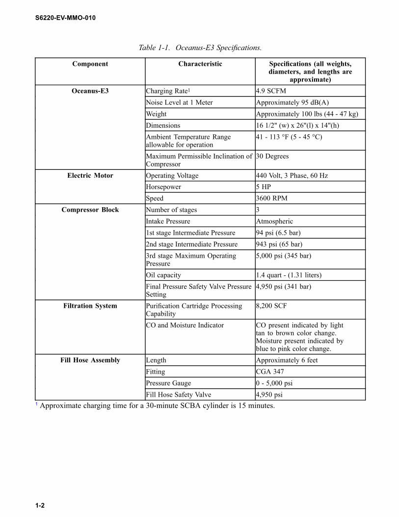
1.2.1 Compliance. The Oceanus-E3 complies with CGA G-7.1, Commodity Specification for Air.1.3 SPECIFICATIONS.Table 1-1 lists Oceanus-E3 specifications. Figure 1-1 provides an illustration of the Oceanus-E3.
1-1
S6220-EV-MMO-010
Table 1-1. Oceanus-E3 Specifications.
Component Characteristic Specifications (all weights,diameters, and lengths are
approximate)Charging Rate1 4.9 SCFMNoise Level at 1 Meter Approximately 95 dB(A)Weight Approximately 100 lbs (44 - 47 kg)Dimensions 16 1/2" (w) x 26"(l) x 14"(h)Ambient Temperature Rangeallowable for operation
41 - 113 °F (5 - 45 °C)
Oceanus-E3
Maximum Permissible Inclination ofCompressor
30 Degrees
Operating Voltage 440 Volt, 3 Phase, 60 HzHorsepower 5 HP
Electric Motor
Speed 3600 RPMNumber of stages 3Intake Pressure Atmospheric1st stage Intermediate Pressure 94 psi (6.5 bar)2nd stage Intermediate Pressure 943 psi (65 bar)3rd stage Maximum OperatingPressure
5,000 psi (345 bar)
Oil capacity 1.4 quart - (1.31 liters)
Compressor Block
Final Pressure Safety Valve PressureSetting
4,950 psi (341 bar)
Purification Cartridge ProcessingCapability
8,200 SCFFiltration System
CO and Moisture Indicator CO present indicated by lighttan to brown color change.Moisture present indicated byblue to pink color change.
Length Approximately 6 feetFitting CGA 347Pressure Gauge 0 - 5,000 psi
Fill Hose Assembly
Fill Hose Safety Valve 4,950 psi1 Approximate charging time for a 30-minute SCBA cylinder is 15 minutes.
1-2

S6220-EV-MMO-010
Figure 1-1. Oceanus-E3.
1.4 SAFETY PRECAUTIONS.Personnel using the Oceanus-E3 shall comply with the safety instructions listed in paragraph 1.4.2 andwith the safety precautions presented in this manual. Operation and maintenance procedures require theuse of high-pressure air, therefore it is important that safety precautions must be understood and followedby all personnel during operation and maintenance procedures.
1.4.1 Standard Safety Precautions. The Oceanus-E3 shall be used only after personnel have beenproperly instructed in its operation. Maintenance of the Oceanus-E3 shall be performed only by personnelwho have read this manual in its entirety. Personnel must use the equipment in accordance with (IAW)posted instructions, labels, and limitations. Personnel must be thoroughly familiar with all safety practicesand understand the potential hazards associated with the Oceanus-E3 before operating or maintaining theequipment.
1.4.2 General Safety Instructions. Standard operational andmaintenance safety precautions containedin the following documents apply to the Oceanus-E3:
• Forces afloat must comply with OPNAVINST 5100.19, Navy Occupational Safety and Health(NAVOSH) Program Manual for Forces Afloat, Vol I/II/III.• Shore activities must comply with OPNAVINST 5100.23, Navy Occupational Safety and Health(NAVOSH) Program Manual.
1.4.3 Special Precautions. The warnings, cautions, and notes appearing throughout this technicalmanual must be followed to prevent injury to personnel and damage to equipment.1.5 EQUIPMENT AND ACCESSORIES SUPPLIED.Table 1-2 provides a listing of the equipment and accessories that are supplied with the Oceanus-E3.
Table 1-2. Equipment and Accessories Supplied.
Quantity Item Reference Number1 Oceanus-E3 Compressor OCEANUS-E3/NAVY1 Cover
1.6 REFERENCE PUBLICATIONS NOT SUPPLIED.Table 1-3 lists reference publications that are not supplied with the Oceanus-E3.
1-3
S6220-EV-MMO-010
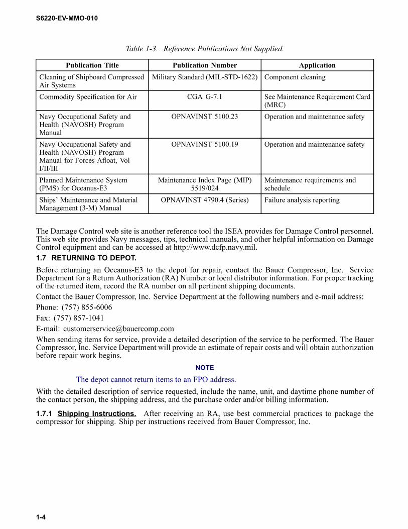
Table 1-3. Reference Publications Not Supplied.
Publication Title Publication Number ApplicationCleaning of Shipboard CompressedAir Systems
Military Standard (MIL-STD-1622) Component cleaning
Commodity Specification for Air CGA G-7.1 See Maintenance Requirement Card(MRC)
Navy Occupational Safety andHealth (NAVOSH) ProgramManual
OPNAVINST 5100.23 Operation and maintenance safety
Navy Occupational Safety andHealth (NAVOSH) ProgramManual for Forces Afloat, VolI/II/III
OPNAVINST 5100.19 Operation and maintenance safety
Planned Maintenance System(PMS) for Oceanus-E3
Maintenance Index Page (MIP)5519/024
Maintenance requirements andschedule
Ships’ Maintenance and MaterialManagement (3-M) Manual
OPNAVINST 4790.4 (Series) Failure analysis reporting
The Damage Control web site is another reference tool the ISEA provides for Damage Control personnel.This web site provides Navy messages, tips, technical manuals, and other helpful information on DamageControl equipment and can be accessed at http://www.dcfp.navy.mil.1.7 RETURNING TO DEPOT.Before returning an Oceanus-E3 to the depot for repair, contact the Bauer Compressor, Inc. ServiceDepartment for a Return Authorization (RA) Number or local distributor information. For proper trackingof the returned item, record the RA number on all pertinent shipping documents.Contact the Bauer Compressor, Inc. Service Department at the following numbers and e-mail address:Phone: (757) 855-6006Fax: (757) 857-1041E-mail: [email protected] sending items for service, provide a detailed description of the service to be performed. The BauerCompressor, Inc. Service Department will provide an estimate of repair costs and will obtain authorizationbefore repair work begins.
NOTE
The depot cannot return items to an FPO address.With the detailed description of service requested, include the name, unit, and daytime phone number ofthe contact person, the shipping address, and the purchase order and/or billing information.
1.7.1 Shipping Instructions. After receiving an RA, use best commercial practices to package thecompressor for shipping. Ship per instructions received from Bauer Compressor, Inc.
1-4

S6220-EV-MMO-010
CHAPTER 2OPERATION
2.1 INTRODUCTION.This chapter contains the following information:
• A description and illustrations of the controls, indicators, and mechanisms of the Oceanus-E3.• Operational use procedures providing compressor setup, compressor startup, and SCBA cylinderassembly air charging procedures. A checklist of these procedures is provided in Appendix A.• Emergency operation procedures. A corresponding checklist is provided in Appendix A.• Post-operating procedures providing compressor shut down and stowage procedures.
2.2 CONTROLS AND INDICATORS.The controls and indicators on each component of the Oceanus-E3 are described in Table 2-1 and illustratedin Figure 2-1. The controls and indicators on the fill hose assembly are described in Table 2-2 and illustratedin Figure 2-2. The following information is provided for each item illustrated:
• Figure Reference Number - identifies corresponding callout• Nomenclature - item name• Function - provides brief description of function of item• Normal Operating Condition - position of item during operational use.
Table 2-1. Oceanus-E3 Controls and Indicators.
Figure 2-1 ReferenceNumber
Nomenclature Function Normal OperatingCondition
1 Final Pressure SafetyValve
Releases compressed airwhen pressure reaches4,950 psi.
Closed
2 CO andMoisture Indicator Provides visualconfirmation when CO ormoisture is present. COwill turn indicator brownand moisture will turnindicator pink.
CO - Light Tan; Moisture- Blue
3 Check Valve Prevents high-pressureair from beingforced back into thecompressor whilecylinders are beingrefilled. Also preventsthe CO and moistureindicator and theP0 filter from beingcontaminated by outsideair.
Closed
4 Pressure MaintainingValve
Maintains a constant backpressure of 2,000 psiwithin the P0 filter systembefore allowing air flow.
Pre-set
2-1

S6220-EV-MMO-010
Table 2-1. Oceanus-E3 Controls and Indicators. - Continued.Figure 2-1 Reference
NumberNomenclature Function Normal Operating
Condition5 P0 Condensate Drain
ValveDrains the condensateaccumulated in the P0filter assembly. Short,periodic openings arerequired after eachcylinder air chargingprocedure is completed.
Closed
6 P0 Bleed Valve Releases pressure in P0purification chamber.
Closed
7 Intermediate SeparatorCondensate Drain Valve
Drains condensate fromthe intermediate separator.Short, periodic openingsare required after eachcylinder air chargingprocedure is completed.
Closed
8 2nd Stage Safety Valve Preventsover-pressurization andlifts at 1,160 psi (77 bar).
Closed
9 Dipstick Indicates oil level incompressor block.
Inserted
10 1st Stage Safety Valve Preventsover-pressurization andlifts at 116 psi (8 bar).
Closed
10
9 8
1
SHROUDS NOT SHOWN IN THIS VIEW
24567 3
Figure 2-1. Oceanus-E3 Controls and Indicators.
2-2

S6220-EV-MMO-010
Table 2-2. Fill Hose Assembly Controls and Indicator.
Figure 2-2 ReferenceNumber
Nomenclature Function Normal OperatingCondition
1 Pressure Gauge Indicates pressure ofcompressed air in attachedSCBA cylinder assembly.
Visible
2 Fill Hose Shutoff Valve Allows air flow fromcompressor to SCBAcylinder assembly.
Open (during charging)
3 Fill Hose Bleed Valve Releases pressure in hoseafter charging.
Closed
4 Fill Hose Safety Valve Releases excess pressure ifSCBA cylinder has beenovercharged.
Closed
0 5000
4000
3000
1000
2000
1 2
34
Figure 2-2. Fill Hose Assembly Controls and Indicator.
2.3 OPERATING PROCEDURES.Paragraphs 2.3.1 and 2.3.2 address operational use and post-operating procedures. Appendix A containsthe corresponding checklist to be copied and used as needed.
2.3.1 Operational Use.2.3.1.1 Compressor Setup.
a. Visually inspect fill hose, fill hose connections, fill hose threads, and pressure gauge (1, Figure2-2) for damage. If damage is observed, repair or replace.
b. Ensure fill hose shutoff valve (2) is closed. Check by turning clockwise (CW).c. Ensure pressure gauge calibration is current.d. Check CO and moisture indicator (Figure 2-3). Indicator display should be light tan (1) and blue
(2). If indicator display is brown (1) and/or pink (2), perform procedures IAW appropriate MRC.
2-3

S6220-EV-MMO-010
2
1
Figure 2-3. Check CO and Moisture Indicator.
WARNING
It is imperative that atmospheric air being drawn into intake filter is as free ofcontaminants as possible. Failure to comply may result in serious injury or deathto personnel.
e. Place compressor in level operational position. If inclination exceeds 30°, shim to less than 30°.f. Remove orange-handled dipstick and wipe dry with clean rag.g. Reinsert dipstick until cap is completely seated. Do not rotate cap.
CAUTION
Compressor oil level must be sufficient to remain between minimum andmaximum indents during operational use to prevent equipment damage.
h. Withdraw dipstick and ensure oil level is between minimum and maximum indents as illustratedin Figure 2-4. If oil level is incorrect, add or remove oil IAW the appropriate MRC.
2-4

S6220-EV-MMO-010
Figure 2-4. Dipstick Indents.
CAUTION
Do not overtighten condensate drain and bleed valves. Overtightening willdamage valve seats and reduce effectiveness of compressor.
i. Ensure P0 condensate drain valve (5, Figure 2-1), P0 bleed valve (6), and intermediatecondensate drain valve (7) are closed (CW).
2.3.1.2 Compressor Start-up.a. Turn (CW) knurled knob (1, Figure 2-5) on final pressure safety valve until fully open.
CAUTION
An ON/OFF switch is not installed on the compressor unit. Ensure 440 voltreceptacle with safety switch is used to avoid arcing and premature operation ofcompressor.
b. Plug compressor power cord into ship’s power receptacle.NOTE
A knocking noise may be heard for the first 10 seconds of operation.c. Turn switch on at ship’s power receptacle.d. Turn knurled knob (1, Figure 2-5) on final pressure safety valve counterclockwise (CCW) until
fully closed.e. When compressor is fully pressurized, the final pressure safety valve (1) will start bleeding
compressed air.
2-5

S6220-EV-MMO-010
SHROUDS NOT SHOWN IN THIS VIEW
3 2
1
Figure 2-5. Compressor Valves.
WARNING
Before venting high-pressure air, ensure all personnel stand clear to avoidserious injury or death from flying debris. Operator shall announce “BLEEDINGDOWN” to warn nearby personnel. Operator must wear protective eyewear andhearing protection to prevent personal injury.
NOTE
Condensate will drain in a few seconds and should be similar to the consistencyand color of skim milk.
f. Open (CCW) P0 condensate drain valve (2) and intermediate separator condensate drain valve(3) and note color and consistency of condensate. If condensate is brownish in color, shut downsystem IAW paragraph 2.3.2.1 and perform corrective maintenance IAW paragraph 6.6.10.
g. Close (CW) P0 condensate drain valve (2) and intermediate separator condensate drain valve(3). Verify by feel that no air is leaking from condensate drain valves.
2-6

S6220-EV-MMO-010
0 50 0 0
40 0 0
30 0 0
10 0 0
20 0 0
0
5
2 3
4
1
Figure 2-6. Fill Hose Assembly Attached to SCBA Assembly.
2.3.1.3 SCBA Cylinder Assembly Air Charging.a. Connect fill hose assembly (1, Figure 2-6) to SCBA cylinder assembly.b. Ensure fill hose bleed valve (4) is closed (CW).c. Open (CCW) SCBA cylinder valve (5) fully, then back off 1/4 turn.
NOTEPressure gauge on fill hose assembly will indicate SCBA cylinder pressure duringcharging. Charging time to fill an SCBA cylinder is approximately 15 minutes.
d. Fully open (CCW) fill hose shutoff valve (3) on fill hose assembly.e. Observe pressure gauge (2). Close (CW) fill hose shutoff valve (3) when pressure gauge indicates
4,500 psi.f. Close (CW) SCBA cylinder valve (5) fully.g. Open (CCW) fill hose bleed valve (4) until air flow stops (2-3 seconds).h. Disconnect SCBA cylinder assembly from fill hose assembly.
WARNING
Before venting high-pressure air, ensure all personnel stand clear to avoidserious injury or death from flying debris. Operator shall announce “BLEEDINGDOWN” to warn nearby personnel. Operator must wear protective eyewear andhearing protection to prevent personal injury.
i. Open (CCW) P0 condensate drain valve (2, Figure 2-5) and intermediate separator condensatedrain valve (3) and drain until no condensate is observed.
j. Close (CW) P0 condensate drain valve (2) and intermediate separator condensate drain valve(3). Verify by feel that no air is leaking from condensate drain valves.
k. If additional SCBA cylinder assemblies need charging, repeat air charging procedures until allbottles have been charged. Otherwise, proceed to paragraph 2.3.2.
2.3.2 Post-Operating Procedures.2.3.2.1 Compressor Shut Down.
2-7

S6220-EV-MMO-010
a. Turn switch off at ship’s power receptacle.b. Unplug compressor power cord.
SHROUDS NOT SHOWN IN THIS VIEW
2 1
Figure 2-7. Compressor Shut Down.
WARNING
Before venting high-pressure air, ensure all personnel stand clear to avoidserious injury or death from flying debris. Operator shall announce “BLEEDINGDOWN” to warn nearby personnel. Operator must wear protective eyewear andhearing protection to prevent personal injury.
CAUTION
Do not open P0 bleed valve (6, Figure 2-1). P0 bleed valve maintains pressure onpurification cartridge. Relieving pressure on cartridge shortens life of cartridge.
c. Open (CCW) condensate drain valves (1 and 2, Figure 2-7) to relieve pressure until air flowstops.
d. Close (CW) condensate drain valves (1 and 2).
2-8

S6220-EV-MMO-010
1
3
2
4
0
20 0 0
10 0 0
30 0 0
40 0 0
50 0 00
Figure 2-8. Fill Hose Assembly.
e. Connect fill hose assembly (1, Figure 2-8) to SCBA cylinder assembly.f. Ensure SCBA cylinder shutoff valve (4) is closed (CW) and fill hose bleed assembly bleed valve
(3) is closed (CW).g. Open (CCW) fill hose shutoff valve (2) fully.
WARNING
Before venting high-pressure air, ensure all personnel stand clear to avoidserious injury or death from flying debris. Operator shall announce “BLEEDINGDOWN” to warn nearby personnel. Operator must wear protective eyewear andhearing protection to prevent personal injury.
h. Slowly open (CCW) fill hose bleed valve (3) until air flow stops and pressure is vented.i. Close (CW) fill hose shutoff valve (2).j. Disconnect fill hose assembly (1) from SCBA cylinder assembly.
2.3.2.2 Stowage.a. Return compressor to compressor foundation.b. Neatly coil hose and connect fill hose assembly coupling to stowage plug on compressor frame
(1, Figure 2-9).
2-9

S6220-EV-MMO-010
21
Figure 2-9. Fill Hose Assembly Stowage Position.
c. Neatly coil electric cord (2).d. Cover compressor.e. Secure compressor with tie-downs.
2-10

S6220-EV-MMO-010
CHAPTER 3FUNCTIONAL DESCRIPTION
3.1 INTRODUCTION.This chapter provides a description of the major components of the Oceanus-E3. The descriptions areintended to provide personnel with a basic understanding of how each component achieves the desiredpurpose.3.2 DESCRIPTION.The Oceanus-E3 is a three-phase, 440 VAC electric air compressor, used to charge Self-ContainedBreathing Apparatus (SCBA) cylinders (4,500 psi) with CGA G-7.1 Grade D air with a moisture contentof 20 mg/m³ (dewpoint of -65°F) or less.The Oceanus-E3 consists of five major components: compressor block, P0 filter system, fill hose,three-phase electric motor, and compressor frame.
3.2.1 Compressor Block. Atmospheric air that is drawn into the compressor block (Figure 3-1) firstpasses through an intake filter and will be compressed through a series of three cylinders, two intercoolers,an intermediate separator and one after-cooler before entering the P0 filter system. The compressor blockutilizes a gravity lubrication system that must be operated in a level position (less than 30° incline). Afanwheel (6) that cools the compressor block is connected to the crankshaft at the end opposite the V-beltpulley and is covered by the front shroud. The paragraphs below give a brief description of how air flowsthrough the compressor during operational use.
9
8
7
1 2
4
6
3
5
Figure 3-1. Compressor Block without Front Shroud.
3.2.1.1 Intake Filter. Atmospheric air is drawn through the intake filter (1) for removal of particles, suchas dust and debris, before entering the 1st stage cylinder.3.2.1.2 1st Stage Cylinder. Air entering the 1st stage cylinder (2), which is at the same pressure asthe ambient air, will be compressed to 94 psi while in the 1st stage cylinder, and then enters the 1st stageintercooler.3.2.1.3 1st Stage Intercooler. The 1st stage intercooler (9) is coiled tubing that is fan-cooled. Thecompressed air is cooled as it flows through the coiled tubing and remains at 94 psi when entering the 2ndstage cylinder. A factory-set safety valve relieves pressure should over-pressurization occur within the 1st
3-1

S6220-EV-MMO-010
stage of compression. This safety valve is located at the end of the 1st stage intercooler coiled tubing justprior to the 2nd stage cylinder.3.2.1.4 2nd Stage Cylinder. The cooled, compressed air enters the 2nd stage cylinder (8) at 94 psi,will be further compressed to 943 psi while in the 2nd stage cylinder, and will then enter the 2nd stageintercooler.3.2.1.5 2nd Stage Intercooler. The second stage intercooler (7) is coiled tubing that is fan-cooled. Thecompressed air is cooled as it flows through the coiled tubing, and remains at 943 psi when entering theintermediate separator. A factory-set safety valve relieves pressure should over-pressurization occur withinthe 2nd stage of compression and is physically located on top of the intermediate separator.3.2.1.6 Intermediate Separator. The intermediate separator (4) is a preliminary air cleaner andmoisture separator. To ensure air is properly cleaned in the intermediate separator and prevent equipmentdamage, the intermediate separator condensate drain on the intermediate separator must be opened for afew seconds after every SCBA cylinder assembly air charging procedure is completed.3.2.1.7 3rd Stage Cylinder. The cooled, clean, compressed air enters the 3rd stage cylinder (5) at 943psi where it will be compressed to 5,000 psi and will then enter the after cooler.3.2.1.8 After Cooler. The after cooler (3) is coiled tubing that is fan-cooled. The compressed air iscooled as it flows through the coiled tubing, then enters the P0 filter system. A factory-set safety valvecontrols the pressure throughout the 3rd stage of compression and is located on the top of the P0 filterassembly housing.
3.2.2 P0 Filter System. As the compressed air passes through each layer of the 3-layer purificationcartridge in the P0 filter system (1, Figure 3-2), moisture and impurities are removed before entering thefill hose assembly connected to an SCBA cylinder assembly. Routine maintenance of the P0 filter system isimperative to ensure proper purification of the air so contaminants do not enter the SCBA cylinder assemblywhile being charged.3.2.2.1 P0 Condensate Drain Valve. The P0 condensate drain valve (3) is the right knob on the baseof the P0 filter assembly housing. To ensure air is properly cleaned and prevent equipment damage, the P0condensate drain valve must be opened for a few seconds after every SCBA cylinder assembly air chargingprocedure is completed.
1
23
4
Figure 3-2. P0 Filter System.
3-2

S6220-EV-MMO-010
3.2.2.2 P0 Bleed Valve. The P0 bleed valve (4) is the left knob on the base of the P0 filter assemblyhousing. The P0 bleed valve is opened only when changing the purification cartridge.3.2.2.3 Purification Cartridge. The purification cartridge (1) contains three layers as follows: a toplayer of catalyst, a middle layer of activated carbon, and a bottom layer of molecular sieve. As compressedair passes through the purification cartridge, moisture and impurities are removed from the compressed air.O-rings on the purification cartridge provide for a proper seal and allow pressure to build up in the P0 filtersystem.3.2.2.4 Pressure Maintaining Valve. The pressure maintaining valve (2) is located on the base of theP0 filter assembly housing and maintains pressure on the filter assembly to prevent moisture contaminationwhen the Oceanus-E3 is in stowage. The pressure maintaining valve is set at the factory and shall not beadjusted.3.2.2.5 CO and Moisture Indicator. The CO and moisture indicator (Figure 3-3) is located betweenthe P0 filter system and the fill hose assembly to provide a visual alert that the compressed air entering thefill hose is contaminated. Should CO be the source, the detection strip color will change from light tan tobrown (2); whereas if moisture contamination is indicated, the detection strip color will change from blueto pink (1).
12
3
Figure 3-3. CO and Moisture Indicator.
3.2.2.6 Check Valve. The check valve (3) prevents high-pressure air from being forced back into thecompressor while cylinders are being refilled. The check valve also prevents the CO and moisture indicatorand the P0 filter from being contaminated by outside air.
3.2.3 Fill Hose Assembly. Purified, compressed air enters the fill hose (Figure 3-4) immediately afterpassing through the P0 filter system. The fill hose is attached to an SCBA cylinder assembly via a CGA347 fitting (1). The fill hose assembly consists of a pressure gauge (2), shutoff valve (3) with a bleed valve(4), safety relief valve (5),and the CGA 347 fitting (1).
3-3

S6220-EV-MMO-010
0 5000
4000
3000
1000
2000
1 2 3
45
Figure 3-4. Fill Hose Assembly.
3.2.4 Electric Motor. The Oceanus-E3 is powered by a 5 HP 440 VAC three-phase electric motor(Figure 3-5) that drives the compressor using a V-belt pulley.
Figure 3-5. Electric Motor.
3.2.5 Compressor Frame. The compressor frame (Figure 3-6) provides structure for tie-down strapsand portability. The compressor frame should only be removed when necessary to facilitate repair.
3-4

S6220-EV-MMO-010
Figure 3-6. Compressor Frame.
3-5/(3-6 blank)


S6220-EV-MMO-010
CHAPTER 4SCHEDULED MAINTENANCE
WARNING
Omission or negligent performance of prescribed maintenance procedures forthis equipment could result in equipment failure and serious injury or death topersonnel.
4.1 INTRODUCTION.Proper scheduling and performance of preventive maintenance actions reduces equipment failures andensures efficient performance of the Oceanus-E3. This chapter outlines safety requirements, defines themaintenance concept, references the Oceanus-E3 PlannedMaintenance System (PMS), discusses reportingrequirements, and provides general maintenance instructions relating to both scheduled and unscheduled(corrective) maintenance actions.4.2 SCOPE.The preventive maintenance requirements for the Oceanus-E3 are addressed in this chapter to assistsupervisors and maintenance personnel in planning, scheduling, and documenting maintenance actions.The information in this chapter supplements the Oceanus-E3 PMS (paragraph 4.5) and is presented inthe following sequence:
• Safety Requirements• Maintenance Concepts• PMS• United States Navy (USN) Maintenance and Material Management (3-M) System Coverageand Problem Reporting• General Maintenance Instructions
4.3 SAFETY REQUIREMENTS.Maintenance personnel shall read and thoroughly understand the safety precautions contained in thismanual and the appropriate Maintenance Requirement Card (MRC) contained in the Oceanus-E3 PMSbefore performing any maintenance on the Oceanus-E3. Forces afloat should also comply with Officeof Naval Operations Instruction (OPNAVINST) 5100.19, Navy Occupational Safety and Health(NAVOSH) Program Manual for Forces Afloat, Vol I/II/III. Shore activities should comply withOPNAVINST 5100.23, Navy Occupational Safety and Health (NAVOSH) Program Manual.4.4 MAINTENANCE CONCEPTS.The Oceanus-E3 maintenance concept is based on the USN PMS, which classifies maintenance into twocategories: scheduled and unscheduled.
4.4.1 Scheduled Maintenance. Scheduled maintenance primarily involves actions required to ensurereliable system operation and includes such actions as inspection, cleaning, lubrication, leak testing, andoperational testing. Scheduled maintenance requirements are provided in the Oceanus-E3 PMS (seeparagraph 4.5).
4.4.2 Unscheduled Maintenance. Unscheduled (corrective) maintenance includes actions required tolocate equipment faults and to correct failures or performance degradations. Unscheduled maintenanceactions include troubleshooting and parts replacements and are performed by maintenance technicians whoare adequately trained in the appropriate service requirements. Unscheduled maintenance is covered inChapter 5, Troubleshooting, and in Chapter 6, Corrective Maintenance.
4-1

S6220-EV-MMO-010
4.5 PLANNED MAINTENANCE SYSTEM.MRCs are indexed and referenced on Maintenance Index Page (MIP) 5519/024, Oceanus-E3. MIP5519/024 provides a summary of the maintenance actions found on the MRCs, along with periodicitycodes, personnel requirements, man-hours, and any related maintenance.4.6 USN MAINTENANCE AND MATERIAL MANAGEMENT (3-M) SYSTEM COVERAGE ANDPROBLEM REPORTING.The provisions of the OPNAVINST 4790.4 series, Ships’ Maintenance and Material Management(3-M) Manual, apply to the Oceanus-E3. Accordingly, any problems or need for corrective maintenancearising from performance of the maintenance actions contained in the Oceanus-E3 MRCs should beproperly reported using OPNAV Form 4790/2K to ensure timely and accurate Maintenance Data System(MDS) documentation of Oceanus-E3 performance in the Fleet. In addition to Fleet requirements,MDS input from Fleet units is used by the In-Service Engineering Agent (ISEA) to identify and correctproblems within the system itself or the related documentation and provisioning, including CoordinatedShipboard Allowance List (COSAL) support. The ISEA may be contacted at Commanding Officer, NavalSurface Warfare Center Panama City, Attn: Code S14, 110 Vernon Avenue, Panama City, FL 32407-7001.4.7 GENERAL MAINTENANCE INSTRUCTIONS.
WARNING
If in doubt about the serviceability of a part, replace it immediately. Wornor damaged parts shall be replaced with authorized replacement parts only.Component failure during operations may result in serious injury or death topersonnel.
WARNING
Do not disassemble components or loosen or tighten fittings while the system ispressurized. Prior to performing maintenance, ensure high-pressure air supplyhas been shut down and all pressure has been bled from the system. Exposure toescaping high-pressure air may result in serious injury or death to personnel.
4.7.1 Equipment Disassembly and Parts Replacement. Disassemble the equipment only to theextent necessary to perform the required maintenance action. Ensure electrical power to the compressorhas been turned off, the compressor has been depressurized, and that proper tag-out procedures areperformed prior to conducting maintenance.If any component fails inspection or testing, replace the worn or damaged part with authorized replacementparts only (see parts lists in paragraph 7.2). Approved general cleaning procedures and lubricants arelisted in the following paragraphs. All the tools, parts, and materials used for maintenance are listed onthe individual MRCs and are identified by their Standard PMS Materials Identification Guide (SPMIG)numbers.
WARNING
Cleanliness is imperative in handling and maintaining the Oceanus-E3. Alltools and parts must be kept free of oil, grease, rust, or other contamination.Contamination of the breathing air system could result in serious injury or deathto personnel.
.
4-2

S6220-EV-MMO-010
WARNING
Use of other than recommended cleaning agents may result in equipment failureand personnel injury or death.
4.7.2 General Cleaning Procedure. Clean is defined as free of all loose scale, rust, grit, filings, dirt,oil, grease, and other foreign substances when viewed by the unaided eye. It is vitally important to keepthe work area and parts clean during maintenance of breathing air systems and equipment.
4.7.3 Lubricants. Only use lubricants authorized on appropriate MRCs. Apply lubricants sparingly.4.7.3.1 Greases. Only use greases authorized on appropriate MRCs. Apply greases sparingly.4.7.3.2 Oil. Add or remove oil in accordance with appropriate MRC.
4.7.4 O-Ring Removal and Installation. If possible, visually inspect O-rings without removing themto avoid unnecessary disassembly that may cause undue wear.4.7.4.1 Inspection. Exposed O-rings which are not required to be removed shall be visually inspectedfor damage and replaced if necessary.
CAUTION
To avoid damage to O-ring groove, remove O-rings using fingers only or theappropriate tool from an O-ring extractor kit.
4.7.4.2 Removal. If an O-ring cannot be removed with fingers, use an O-ring installation/removal tool.Scratching the O-ring groove may cause leakage or premature seal failure. Unless otherwise directed, allremoved O-rings shall be cut and discarded.4.7.4.3 Installation. Strict cleanliness and proper lubrication are essential during O-ring installation.Ensure new O-rings are of the proper size and material. To ensure correct installation, observe thefollowing:
• Visually inspect new O-rings for deformities or compression set, hardening or brittleness, nicks orcuts, pits or blisters, or any other signs of damage. Cut and discard damaged O-rings and obtainnew O-rings for replacement.• Ensure parts are clean throughout the installation procedure. Dirt, chips, or foreign particles inO-ring grooves can cause leakage or damage to O-rings.• Lubricate O-rings before assembly. Use only approved lubricants for O-rings. Apply lubricantsparingly; excess lubricant can foul other components.• Do not overstretch O-rings during installation. To avoid O-ring damage, stretch only as neededfor proper installation.• Ensure O-rings are not twisted in groove as twisting occurs easily during replacement of largeO-rings with relatively small cross-sectional diameters.• Do not force O-rings over corners, threads, splines, ports, or other sharp edges. Use thimble,support, cone, or other device to prevent O-rings from contacting sharp edges of parts.
4-3/(4-4 blank)


S6220-EV-MMO-010
CHAPTER 5TROUBLESHOOTING
5.1 INTRODUCTION.This chapter contains the troubleshooting procedures and data necessary to assist personnel in locatingthe source of equipment malfunction or performance degradation in the Oceanus-E3. Table 5-1 presentssymptoms that may occur during operation of the Oceanus-E3 and suggests possible causes and actionsthat should correct the problem. Removal and installation procedures are provided in Chapter 6.5.2 GENERAL TROUBLESHOOTING INSTRUCTIONS.Troubleshooting is based on locating potential faults in the equipment and taking timely corrective action.This manual cannot possibly list all malfunctions that may occur nor all causes, tests, inspections, orcorrective actions that may apply. If a malfunction is not listed or is not remedied by the suggestedcorrective action(s), notify the supervisor.
Table 5-1. Troubleshooting Guidelines.
Symptom Possible Cause(s) Corrective Action(s)a. Ensure Oceanus-E3 is plugged inand switch is turned on.
Oceanus-E3 will not begin running. Insufficient source of electricity.
b. Ensure ship’s 440 VAC source isavailable.
a. Condensate drain valves open. a. Close (CW) condensate drainvalves.
b. P0 purification cartridge notseated properly.
b. Re-seat P0 purification cartridgeIAW appropriate MRC.
c. V-belt slippage. c. Adjust V-belt IAW paragraph6.6.2.
d. Clogged intake filter. d. Replace intake filter IAWappropriate MRC.
e. Defective final pressure safetyvalve.
e. Replace final safety pressurevalve IAW paragraph 6.6.7.
Pressure not building up in systemduring operation or excessivecharging times (greater than 20minutes per cylinder assembly).
f. Worn floating piston (more likelyafter 5 years of use).
f. Return Oceanus-E3 fordepot-level repair IAW paragraph1.7.
a. If there is air flow through fillhose assembly, then defective reliefvalve.
a. Replace defective safety reliefvalve IAW appropriate paragraphs6.6.5 and 6.6.6.
1st and/or 2nd safety valve lifting.
b. If there is no air flow throughfill hose assembly, then internalcompressor block componentfailure.
b. Return Oceanus-E3 fordepot-level repair IAW paragraph1.7.
a. Oil is over-filled. a. Drain excess oil IAW appropriateMRC. Perform sanitation procedureIAW 6.6.10.
Condensate is tan in color (air iscontaminated with compressorblock oil).
b. Compressor operation while atan incline in excess of 30°.
b. Perform sanitation procedureIAW 6.6.10.
5-1

S6220-EV-MMO-010
Table 5-1. Troubleshooting Guidelines. - Continued.Symptom Possible Cause(s) Corrective Action(s)
a. Clogged intake filter. a. Replace intake filter IAWappropriate MRC.
Overheating is observed (paintpeeling, smoke, compressor frameis hot to touch, etc.). b. Low or no oil in compressor
block.b. Add oil IAW appropriate MRC.
Knocking noise heard for more than10 seconds after start-up.
Free-floating piston not seatingproperly.
Return Oceanus-E3 for depot-levelrepair IAW paragraph 1.7.
5-2
S6220-EV-MMO-010
CHAPTER 6CORRECTIVE MAINTENANCE
6.1 INTRODUCTION.
6.1.1 Scope. The corrective maintenance information presented in this chapter includes the actionsand procedures required to restore the Oceanus-E3 equipment to a fully operable condition. This chapterprovides general maintenance information and specific maintenance procedures to assist maintenancepersonnel in the removal and replacement of inoperative parts or assemblies. The corrective maintenanceprocedures identify maintenance actions; provide safety precautions; list tools, parts, and materials; andpresent step-by-step instructions with supporting illustrations. The corrective maintenance procedures inthis chapter are provided for qualified maintenance personnel working at the organizational level.The procedures included in this chapter are prescribed in the interest of safety and optimum service life ofthe equipment. Components requiring correctivemaintenance beyond the limits described in this documentmust be returned to the depot (in accordance with [IAW] paragraph 1.7) for repair or overhaul.
The information in the remainder of this chapter is arranged in the following sequence:General Maintenance InformationTest Equipment and ToolsMaterialsGeneral Maintenance ProceduresOceanus-E3 Corrective Maintenance.
6.1.2 Safety Requirements. Before performing corrective maintenance on the Oceanus-E3,maintenance personnel shall review and become thoroughly familiar with the general safety notices andprecautions listed in the Safety Summary. Replacement procedures, along with the associated warningsand cautions, shall be read in full before beginning corrective maintenance.6.2 GENERAL MAINTENANCE INFORMATION.
CAUTION
If in doubt about the serviceability of a part, replace it immediately. Worn ordamaged parts shall be replaced with authorized replacement parts only. Failureto comply may result in equipment damage.
6.2.1 Maintenance Parts. Only approved replacement parts listed in Chapter 7 shall be used on theOceanus-E3.
6.2.2 Related Maintenance. Related corrective maintenance actions may include inspection, removal,and replacement of O-rings, as well as inspection of component parts. O-ring inspection, removal, andreplacement procedures are provided in paragraph 4.7.4. Ensure cleanliness of the system is maintained atall times IAW the requirements in paragraphs 4.7.1 and 4.7.2.6.3 TEST EQUIPMENT AND TOOLS.No special test equipment is required for corrective maintenance on the Oceanus-E3. Table 6-1 lists thetools used in this chapter.
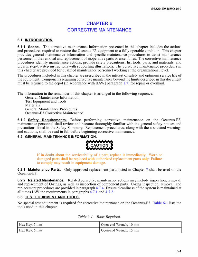
Table 6-1. Tools Required.
Hex Key, 5 mm Open-end Wrench, 10 mmHex Key, 6 mm Open-end Wrench, 15 mm
6-1

S6220-EV-MMO-010
Table 6-1. Tools Required. - Continued.Open-end Wrench, 5/8 inch Open-end Wrench, 17 mm
Open-end Wrenches (2), 1/2 inch Open-end Wrench, 24 mmOpen-end Wrench, 3/4 inch Screwdriver, Phillips-head, #3Open-end Wrench, 9/16 inch Socket, 5/16 inch with reversible ratchet handleOpen-end Wrench, 1 1/8 inch Straight Edge
6.4 MATERIALS.The only material used in this chapter is anti-seize tape MIL-T-27730 (Teflon tape).6.5 GENERAL MAINTENANCE PROCEDURES.
CAUTION
Disassembly of the Oceanus-E3 components beyond the procedures describedin this manual shall not be performed. Additional disassembly may causecomponent failure.
6.6 CORRECTIVE MAINTENANCE.
6.6.1 Compressor Frame and Shrouds Removal and Installation.a. Tools, Parts, and Materials.
(1) Hex key, 5 mm(2) Open-end wrench, 10 mm(3) Screwdriver, Phillips head, #3
b. Front Shroud Removal.(1) Using #3 Phillips head screwdriver, remove (CCW) four screws (top, Figure 6-2) holding
front shroud in place.c. Compressor Frame Removal.
6-2

S6220-EV-MMO-010
1
2
3
4
5
Figure 6-1. Compressor Frame Removal.
(1) Disconnect fill hose from frame.(2) Begin removing the frame at the front left side of the compressor (1, Figure 6-1). Use 5 mm
hex key and turn CCW to loosen and remove bolts while using 10 mm open-end wrench tohold hex nut.
(3) At the back of the compressor (2), by the intermediate filter condensate drain, remove(CCW) two bolts using 5 mm hex key while using 10 mm open-end wrench to hold hexnut.
(4) On the right side center of the compressor (3), remove (CCW) one bolt using 5 mm hex key.(5) On front right side of compressor (5), remove (CCW) two bolts using 5 mm hex key.(6) On the front right side of the compressor (4), inside the frame, remove (CCW) one bolt
using the 5 mm hex key. Frame must be lifted as bolt is removed.
6-3

S6220-EV-MMO-010
FRONT SHROUD
REAR SHROUD
1
2
Figure 6-2. Front and Rear Shroud Removal.
d. Rear Shroud Removal.(1) To remove rear shroud, use 5 mm hex key to remove (CCW) two hex head bolts (1, Figure
6-2).(2) Remove “H” clamp (2) holding shroud in place.(3) Disconnect P0 drain tube from intermediate separator drain tube.(4) Remove shroud from compressor by lifting and slightly twisting to free shroud from
intermediate separator condensate valve.e. Rear Shroud Installation.
(1) Install rear shroud by slightly twisting and placing over fanwheel, avoiding contact withintermediate separator condensate valve.
(2) Connect P0 drain tube to intermediate separator drain tube.(3) Secure rear shroud to compressor by attaching “H” clamp and fastening (CW) with two 5
mm hex head screws.f. Compressor Frame Installation.
NOTE
Use washers (3, Figure 7-1) between frame and all bolt heads and nuts.(1) On the front right side of the compressor, (4, Figure 6-1) inside the frame, install one bolt
using the 5 mm hex key (CW).(2) On the right side center of the compressor, install (CW) one bolt (3) and two bolts (5) using
5 mm hex key.
6-4

S6220-EV-MMO-010
(3) At the back of the compressor (2), by the condensate drain, install (CW) two bolts and nutsusing 5 mm hex key and 10 mm open-end wrench.
(4) At the front left side of the compressor (1), install (CW) two bolts and nuts using the 5 mmhex key and 10 mm open-end wrench.
(5) Reconnect fill hose to compressor frame.g. Front Shroud Installation.
(1) Install the front shroud using #3 Phillips head screwdriver and four screws (CW) as shownin Figure 6-2.
6.6.2 V-Belt Adjustment.a. Tools, Parts, and Materials.
(1) Straight edge(2) Open-end wrenches (2), 1/2 inch(3) Socket, 5/16 inch with reversible ratchet handle
b. Adjustment.
WARNING
Power supply must be unplugged prior to conducting corrective maintenance.Failure to comply may result in serious injury or death to personnel.
(1) Ensure electric power cord has been unplugged.(2) Remove front shroud IAW procedures in paragraph 6.6.1.b.
NOTE
Lock nuts on bottom of electric motor plate (4, Figure 6-3) may be easier to loosenthan bolts (1) on top of base plate.
(3) Using two 1/2-inch open-end wrenches, one wrench holding the nut in place while otherwrench turns the bolt CCW, loosen two bolts (1, Figure 6-3) on each side of electric motor(2) until it can slide on the base plate (3).
6-5

S6220-EV-MMO-010
1
2
4
3
Figure 6-3. Loosening Bolts on Electric Motor.
APPROXIMATE DEFLECTION3/8" (10 mm)
Figure 6-4. Approximate V-Belt Deflection.
(4) Adjust electric motor position until the v-belt deflection is approximately 3/8 inch asillustrated in Figure 6-4.
6-6

S6220-EV-MMO-010
(5) Hold straight edge against the middle of both pulleys. Ensure the straight edge touches thepulleys at all points (1, Figure 6-5).
(6) Using two 1/2-inch open-end wrenches, one wrench holding the nut in place while otherwrench turns the bolt (CW), tighten bolts on electric motor.
WARNING
The shroud is off when performing the next step; personnel should exerciseextreme caution. Failure to comply may result in injury or death to personnel.
(7) Operate the compressor IAW paragraph 2.3.1 for 5 minutes.(8) Shut down the compressor IAW paragraph 2.3.2.1.(9) Check for v-belt deflection of approximately 3/8 inch as illustrated in Figure 6-4.(10) Hold straight edge against the middle of both pulleys. Ensure the straight edge touches
the pulleys at all points (1, Figure 6-5). If proper alignment is not achieved in previoussteps, (i.e., pulley sheave needs to slide on motor shaft) proceed to step (11). If alignmentis correct, proceed to step (15).
WHERE STRAIGHTEDGE INTERSECTS4 POINTS ON PULLEYS
1
4
3
25
6
6
6
Figure 6-5. Proper Pulley Alignment.
NOTE
The pulley adjustment step below is also an alternate method of changing the belt.(11) To adjust pulley alignment, begin by removing (CCW) three 5/16 inch bolts (2) from
non-threaded holes in pulley bushing (3) using 5/16 socket.(12) Insert three 5/16 inch bolts (2) into threaded holes (6) in pulley bushing (3), using 5/16 inch
socket and turn CW to tighten bolts. This action pulls pulley bushing away from pulley (4)allowing the pulley to be moved along the motor shaft.
(13) After pulley (4) alignment has been adjusted, remove three 5/16 inch bolts (2) from threadedholes (6) in pulley bushing (3) with 5/16 inch socket, turning CCW. Reinsert bolts (2) intonon-threaded pulley bushing holes.
(14) If further adjustment is required, repeat procedures in steps (3) and (4) until proper deflectionis obtained.
(15) Reattach front shroud IAW procedures in paragraph 6.6.1.g.
6.6.3 V-Belt Removal and Installation.
6-7

S6220-EV-MMO-010
a. Tools, Parts, and Materials.(1) Straight edge(2) Open-end wrenches (2), 1/2 inch(3) Socket, 5/16 inch with reversible ratchet handle(4) V-belt (3, Figure 7-2)
b. Removal.(1) Ensure power cord is unplugged.(2) Begin v-belt removal by removing front shroud IAW procedures in paragraph 6.6.1.b.(3) Loosen bolts securing electric motor using two 1/2 inch open-end wrenches IAW paragraph
6.6.2.b.(3).(4) Slide electric motor towards compressor block to loosen tension on v-belt.(5) Remove v-belt from pulleys.
c. Installation.(1) Inspect replacement v-belt for cracks, scuffing, or other damage. If damage is noted, install
new v-belt.(2) Install v-belt on pulleys.(3) Slide electric motor away from compressor block to increase tension on v-belt.(4) Holding the straight edge against the pulleys, ensure that the straight edge touches the
pulleys at all points as shown in Figure 6-5.(5) Check that the v-belt has deflection of approximately 3/8 inch as shown in Figure 6-4.(6) Using two 1/2 inch open-end wrenches, tighten (CW) four bolts (1, Figure 6-3) to secure
electric motor.(7) Reattach front shroud and compressor frame IAW procedures in paragraph 6.6.1.g.
6.6.4 Electric Motor Removal and Installation.a. Tools, Parts, and Materials.
(1) Straight edge(2) Open-end wrenches, 1/2 inch(3) Socket, 5/16 inch with reversible ratchet handle(4) Electric motor (3, Figure 7-3)
b. Removal.(1) Ensure power cord has been disconnected.(2) Remove compressor frame and shrouds IAW procedures in paragraphs 6.6.1. b through d.(3) Remove v-belt IAW procedures in paragraph 6.6.3.b.
NOTE
Lock nuts on bottom of electric motor plate (4, Figure 6-3) may be easier to loosenthan bolts (1) on top of base plate.
(4) Using two 1/2 inch wrenches (one wrench holds nut in place while other wrench turns boltCCW), remove four bolts (1, Figure 6-4) and nuts (4) that secure electric motor (2) to baseplate (3).
(5) Use 5/16 inch socket to remove (CCW) three 5/16 inch bolts (2, Figure 6-5) fromnon-threaded holes on pulley bushing (3).
(6) Insert three 5/16 inch bolts (2) into threaded pulley bushing holes (6), using 5/16 inch socketand turning CW to tighten. This action pulls the pulley bushing away from the pulley.
6-8

S6220-EV-MMO-010
(7) Tighten (CW) bolts (2) until pulley bushing is free from pulley and remove pulley bushingfrom motor shaft.
(8) Remove (CCW) 5/16 inch bolts (2) from threaded holes (6) and reinsert into non-threadedpulley bushing holes.
(9) Remove pulley (4) with key (5) and v-belt from motor shaft.(10) Remove electric motor.
c. Installation.(1) Position electric motor in place on base plate (3, Figure 6-3).(2) Using two 1/2 inch open-end wrenches, one wrench holding nut in place while other wrench
turns bolt CW, install bolts (1) on each side of electric motor (2). Do not tighten.(3) Place pulley bushing (3, Figure 6-5) on pulley (4).(4) Place key (5) in key way on motor shaft and align pulley on motor shaft.(5) Inspect v-belt for cracks, scuffing or other damage. If damage is noted, install new v-belt.
CAUTION
Do not force v-belt around pulleys. Slide electric motor toward pulleys to reducetension on v-belt. Failure to comply may result in equipment damage.
(6) Place v-belt around both pulleys. Slide electric motor toward compressor block to loosentension if v-belt does not easily fit around pulleys.
(7) Complete adjustment of v-belt IAW procedures in paragraph 6.6.2.b.(8) Reattach shrouds and compressor frame IAW procedures in paragraphs 6.6.1.e through g.
6.6.5 1st Stage Safety Valve Removal and Installation.
WARNING
Ensure system is bled down before removing valves. Failure to complymay resultin injury or death to personnel.
a. Tools, Parts, and Materials.(1) Open-end wrench, 15 mm(2) Open-end wrench, 24 mm(3) 1st Stage Relief Valve with Crush Washer (7, Figure 7-4)
b. Removal.(1) Ensure power cord is unplugged.
CAUTION
Position wrench only as shown in 1, Figure 6-6. Failure to comply may result inequipment damage.
NOTE
Valve removal procedures are intended only for valve calibration or replacement.(2) Using 15 mm open-end wrench, turn CCW to loosen while holding fitting in place with 24
mm wrench and remove 1st stage safety valve (1, Figure 6-6) and crush washer (2).
6-9
S6220-EV-MMO-010
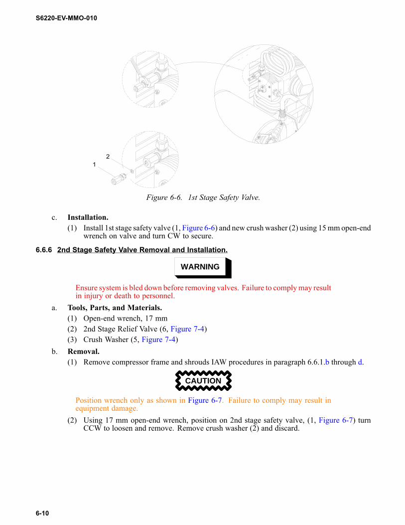
21
Figure 6-6. 1st Stage Safety Valve.
c. Installation.(1) Install 1st stage safety valve (1, Figure 6-6) and new crush washer (2) using 15mmopen-end
wrench on valve and turn CW to secure.
6.6.6 2nd Stage Safety Valve Removal and Installation.
WARNING
Ensure system is bled down before removing valves. Failure to complymay resultin injury or death to personnel.
a. Tools, Parts, and Materials.(1) Open-end wrench, 17 mm(2) 2nd Stage Relief Valve (6, Figure 7-4)(3) Crush Washer (5, Figure 7-4)
b. Removal.(1) Remove compressor frame and shrouds IAW procedures in paragraph 6.6.1.b through d.
CAUTION
Position wrench only as shown in Figure 6-7. Failure to comply may result inequipment damage.
(2) Using 17 mm open-end wrench, position on 2nd stage safety valve, (1, Figure 6-7) turnCCW to loosen and remove. Remove crush washer (2) and discard.
6-10
S6220-EV-MMO-010
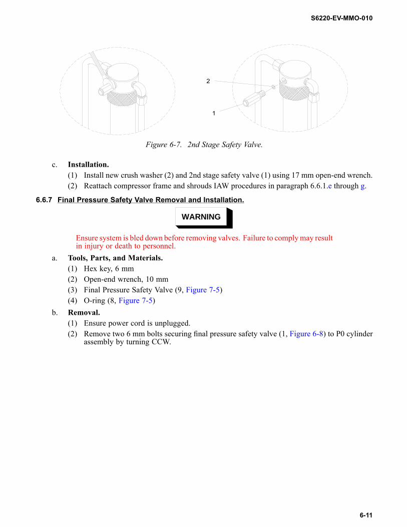
2
1
Figure 6-7. 2nd Stage Safety Valve.
c. Installation.(1) Install new crush washer (2) and 2nd stage safety valve (1) using 17 mm open-end wrench.(2) Reattach compressor frame and shrouds IAW procedures in paragraph 6.6.1.e through g.
6.6.7 Final Pressure Safety Valve Removal and Installation.
WARNING
Ensure system is bled down before removing valves. Failure to complymay resultin injury or death to personnel.
a. Tools, Parts, and Materials.(1) Hex key, 6 mm(2) Open-end wrench, 10 mm(3) Final Pressure Safety Valve (9, Figure 7-5)(4) O-ring (8, Figure 7-5)
b. Removal.(1) Ensure power cord is unplugged.(2) Remove two 6 mm bolts securing final pressure safety valve (1, Figure 6-8) to P0 cylinder
assembly by turning CCW.
6-11
S6220-EV-MMO-010
3
2
5 6
4
1
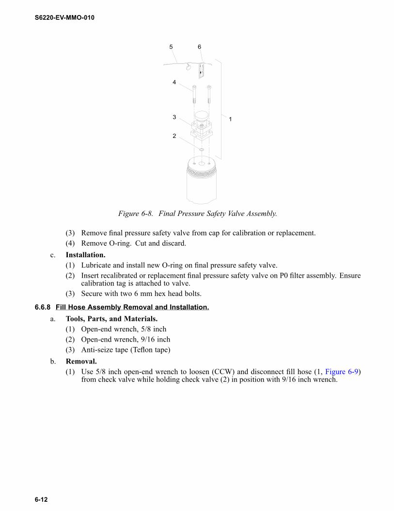
Figure 6-8. Final Pressure Safety Valve Assembly.
(3) Remove final pressure safety valve from cap for calibration or replacement.(4) Remove O-ring. Cut and discard.
c. Installation.(1) Lubricate and install new O-ring on final pressure safety valve.(2) Insert recalibrated or replacement final pressure safety valve on P0 filter assembly. Ensure
calibration tag is attached to valve.(3) Secure with two 6 mm hex head bolts.
6.6.8 Fill Hose Assembly Removal and Installation.a. Tools, Parts, and Materials.
(1) Open-end wrench, 5/8 inch(2) Open-end wrench, 9/16 inch(3) Anti-seize tape (Teflon tape)
b. Removal.(1) Use 5/8 inch open-end wrench to loosen (CCW) and disconnect fill hose (1, Figure 6-9)
from check valve while holding check valve (2) in position with 9/16 inch wrench.
6-12

S6220-EV-MMO-010
1
2
Figure 6-9. Fill Hose Connected to Check Valve.
(2) Unscrew (CCW) other end of fill hose from frame stowage position, if attached.c. Installation.
(1) Thoroughly clean male and female threads of fill hose connection (1) and check valve,removing all previously applied anti-seize (Teflon) tape. Do not allow tape particles toenter the valves.
(2) Wrap anti-seize (Teflon) tape around male threads in a spiral direction, starting at the secondor third thread. Encircle the threads three times.
(3) Using 5/8 inch open-end wrench, turn CW to attach fill hose to check valve, holding checkvalve in place with 9/16 inch open-end wrench.
(4) Attach fill hose to frame stowage position.
6.6.9 Check Valve Removal and Installation.a. Tools, Parts, and Materials.
(1) Open-end wrench, 1 1/8 inch(2) Anti-seize tape (Teflon tape)(3) Check Valve (2, Figure 7-5)(4) Open-end wrench, 3/4 inch
b. Removal.(1) Before removing check valve, follow procedure in paragraph 6.6.8.b to remove fill hose.(2) Using 1 1/8 inch open-end wrench on check valve, turn CCW to loosen, then remove. Use
3/4 inch wrench on fitting below check valve to hold in place.c. Installation.
(1) Thoroughly clean male and female threads of check valve and connection, removing allpreviously applied anti-seize (Teflon) tape. Do not allow tape particles to enter the valves.
(2) Wrap anti-seize (Teflon) tape around male threads of check valve connection in a spiraldirection, starting at the second or third thread. Encircle the threads three times.
(3) Using 1 1/8 inch open-end wrench on check valve, turn CW to secure and use 3/4 inchwrench on fitting below to hold in place.
6-13

S6220-EV-MMO-010
(4) Follow procedure in paragraph 6.6.8.cto install fill hose onto check valve.
6.6.10 Sanitizing Compressor After Oil Contamination.a. Tools, Parts, and Materials.
No tools, parts, or materials are required to sanitize system.b. Sanitizing Compressor.
(1) Start compressor IAW paragraph 2.3.1 and allow to run for 5 minutes. This will build uppressure inside the system.
(2) Drain the P0 condensate drain valve intermediate separator condensate drain valve andobserve discharge. If discharge is brownish, continue performing previous step untildischarge observed is pale white. This process should not take longer than 6 cycles (30minutes) to complete.
(3) After observed discharge changes color to pale white, perform step (1) above two additionalcycles. If brownish discharge is still present after 1 hour, tag the compressor as “Out ofService” and follow procedures in paragraph 1.7 to return the compressor for depot-levelrepair.
(4) Change purification cartridge.(5) Store compressor IAW procedures in paragraph 2.3.2.2.
6-14

S6220-EV-MMO-010
CHAPTER 7ILLUSTRATED PARTS BREAKDOWN
7.1 INTRODUCTION.This chapter provides the Illustrated Parts Breakdown (IPB) for the Oceanus-E3. Each assembly orcomponent has an exploded or cutaway view of the item and a corresponding table listing the parts andinformation necessary for ordering.7.2 PARTS LISTS AND ILLUSTRATIONS.Figures 7-1 through 7-5 provide parts lists for principle Oceanus-E3 components. Table column headingsare as follows:
FIGURE - ITEM NO.: Indicates the figure and item numbers relating to part location on thecorresponding illustration.CAGE: Identifies the Commercial and Government Entity (CAGE) code for the part manufacturer.PART NO.: The Federal Logistics Record (FEDLOG) part number is provided, which is themanufacturer’s part number.DESCRIPTION: Contains the item nomenclature and pertinent descriptive data about the part.QTY: Indicates the quantity required per assembly.
7-1

S6220-EV-MMO-010
A
A
38
8
3
1
3
7
37
37
7
1
3
2
37
3654
31332
10
3
3
1
13
13
9
31
Figure 7-1. Compressor Frame Parts.
7-2

S6220-EV-MMO-010
Table 7-1. Compressor Frame Parts List.
FIGURE 7-1 ITEMNO.
CAGE PART NO. DESCRIPTION QTY
1 39428 91292A137 Socket Head CapScrew M6 x 20 mm
7
2 39428 91292A142 Socket Head CapScrew M6 x 40 mm
2
3 80205 MS15795-853 Flat Washer 164 53711 7246035-1 Polyurethane Foot 45 80205 MS15795-814 Flat Washer 46 39428 91287A168 Hex Head Cap
Screw M10 pitch1-5 mm x 16 mm
4
7 39428 93625A250 Lock Nut, M6 58 39428 91292A143 Socket Head Cap
Screw, M6 x 45 mm2
9 53711 7246034-1 Spacer 110 53711 7246032-1 Oceanus Electric
Compressor FrameAssembly
1
7-3

S6220-EV-MMO-010
2
1
54
3
Figure 7-2. Front and Rear Shroud Parts.
7-4

S6220-EV-MMO-010
Table 7-2. Front and Rear Shroud Parts List.
FIGURE 7-2 ITEMNO.
CAGE PART NO. DESCRIPTION QTY
1 57328 N15769 Socket Head CapScrew M6 x 16 mm
2
2 57328 77674 H-Clamp 13 57328 BET-0172 V-Belt 14 57328 SPC-0024 Plastic Washer 45 57328 SCR-0292 #3 Self-Tapping
Phillips Screw4
7-5

S6220-EV-MMO-010
5
62
7
8
9
32
1
4
Figure 7-3. Electric Motor and Pulley Parts.
7-6

S6220-EV-MMO-010
Table 7-3. Electric Motor and Pulley Parts List.
FIGURE 7-3 ITEMNO.
CAGE PART NO. DESCRIPTION QTY
1 57328 N17082 Self-Locking CapScrew
4
2 57328 N02460 Washer 83 57328 MTR-0022 5 HP Electric Motor 14 99820 M19622-19-0001 Electrical Packing 15 57328 M2726/3-001 Electric Plug 16 57328 NUT-0119 Lock Nut 47 57328 078019 Motor Brace 28 57328 SHE-0246 Motor Pulley 19 57328 BUS-0031 Pulley Bushing 1
7-7

S6220-EV-MMO-010
6
7
8
5
43
21
Figure 7-4. Air Intake and Safety Valves Parts.
7-8

S6220-EV-MMO-010
Table 7-4. Air Intake and Safety Valves Parts List.
FIGURE 7-4 ITEMNO.
CAGE PART NO. DESCRIPTION QTY
1 57328 N04877 Intake Filter CapO-Ring
1
2 57328 N04823 Intake Air Filter 13 57328 059433 Filter Cap 14 57328 N4870 Knurled Nut 15 57328 64498 Crush Washer (2nd
Stage)1
6 57328 012886 2nd Stage SafetyRelief Valve
1
7 57328 010776 1st Stage SafetyRelief Valve(includes #8-CrushWasher)
1
8 57328 8263 Crush Washer (1stStage)
1
7-9

S6220-EV-MMO-010
8
3
2
4 1
56
7
9
10
Figure 7-5. Filter Assembly Parts.
7-10

S6220-EV-MMO-010
Table 7-5. Filter Assembly Parts List.
FIGURE 7-5 ITEMNO.
CAGE PART NO. DESCRIPTION QTY
1 57328 IND-0015 CO and MoistureIndicator Assembly
1
2 57328 ELM-0056 Indicator Element(includes CO andmoisture strips)
1
3 57328 N04483 CO and MoistureIndicator O-Ring
1
4 57328 VAL-0176 Check Valve 15 57328 N25212 P0 Filter Assembly
O-Ring (outer)1
6 57328 N04586 P0 Filter AssemblyO-Ring (inner)
2
7 57328 059183A PurificationCartridge
1
8 57328 N04882 Final PressureSafety Valve O-Ring
1
9 57328 059410 Final PressureSafety Valve
1
10 57328 SCR-0139 Socket Head CapScrew
4
7-11

S6220-EV-MMO-010
1
2
11
10
9
87
6
5
4
3
Figure 7-6. Fill Hose Assembly Parts.
7-12

S6220-EV-MMO-010
Table 7-6. Fill Hose Assembly Parts List.
FIGURE 7-6 ITEMNO.
CAGE PART NO. DESCRIPTION QTY
1 57328 CVR-0002 Gauge Cover 12 57328 GAG-0010W Pressure Gauge 13 57328 HOS-0080 Fill Hose 14 57328 CON-0348 Male Connector 15 57328 VAL-0006 Fill Hose Shutoff
Valve1
6 57328 ADP0325 Adapter 17 57328 CON0017SS Male Connector 18 57328 VAL-0169 Safety Relief Valve 19 57328 CON0042SS Cross Connector 110 57328 ADP-0113 CGA 347 Coupling 111 57328 N04483 Nipple O-Ring 1
7-13

S6220-EV-MMO-010
7.3 LIST OF MANUFACTURERSTable 7-7 below lists the manufacturers and their Commercial and Government Entity (CAGE) Codes forall of the parts listed in Chapter 7.
Table 7-7. List of Manufacturers.
CAGE Code Manufacturer39428 McMaster-Carr Supply Company
600 County Line RoadElmhurst, IL 60126-2081(630) 833-0300
53711 Naval Sea Systems Command1333 Isaac Hull Ave., S.E.Washington Navy YardWashington DC 20376
57328 Bauer Compressors, Inc.1328 Azalea Garden RoadNorfolk VA 23502-1944(757) 855-6006
80205 National Aerospace Standards CommitteeAerospace Industries Association of America Inc.
99820 Dorn Equipment Corp.27 Upham St.Melrose, MA 02176-6350(781) 662-9300
7-14
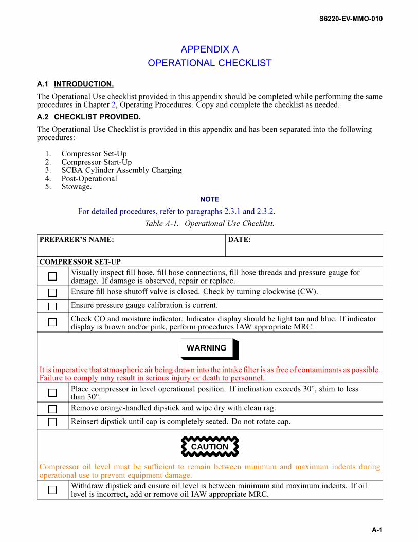
S6220-EV-MMO-010
APPENDIX AOPERATIONAL CHECKLIST
A.1 INTRODUCTION.The Operational Use checklist provided in this appendix should be completed while performing the sameprocedures in Chapter 2, Operating Procedures. Copy and complete the checklist as needed.A.2 CHECKLIST PROVIDED.The Operational Use Checklist is provided in this appendix and has been separated into the followingprocedures:
1. Compressor Set-Up2. Compressor Start-Up3. SCBA Cylinder Assembly Charging4. Post-Operational5. Stowage.
NOTE
For detailed procedures, refer to paragraphs 2.3.1 and 2.3.2.Table A-1. Operational Use Checklist.
PREPARER’S NAME: DATE:
COMPRESSOR SET-UPVisually inspect fill hose, fill hose connections, fill hose threads and pressure gauge fordamage. If damage is observed, repair or replace.Ensure fill hose shutoff valve is closed. Check by turning clockwise (CW).
Ensure pressure gauge calibration is current.
Check CO and moisture indicator. Indicator display should be light tan and blue. If indicatordisplay is brown and/or pink, perform procedures IAW appropriate MRC.
WARNING
It is imperative that atmospheric air being drawn into the intake filter is as free of contaminants as possible.Failure to comply may result in serious injury or death to personnel.
Place compressor in level operational position. If inclination exceeds 30°, shim to lessthan 30°.Remove orange-handled dipstick and wipe dry with clean rag.
Reinsert dipstick until cap is completely seated. Do not rotate cap.
CAUTION
Compressor oil level must be sufficient to remain between minimum and maximum indents duringoperational use to prevent equipment damage.
Withdraw dipstick and ensure oil level is between minimum and maximum indents. If oillevel is incorrect, add or remove oil IAW appropriate MRC.
A-1

S6220-EV-MMO-010
Table A-1. Operational Use Checklist. - Continued.
CAUTION
Do not overtighten condensate drain and bleed valves. Overtightening will damage valve seats and reduceeffectiveness of compressor.
Ensure P0 condensate drain valve, P0 bleed valve, and intermediate condensate drain valveare closed (CW).
COMPRESSOR START-UPTurn (CW) knurled knob on final pressure safety valve until fully open.
CAUTION
An ON/OFF switch is not installed on the compressor unit. Ensure 440 volt receptacle with safety switchis used to avoid arcing and premature operation of compressor.
Plug in compressor power cord to ship’s power receptacle.
NOTE
A knocking noise may be heard for the first 10 seconds of operation.Turn switch on at ship’s power receptacle.
Turn knurled knob on final pressure safety valve counterclockwise (CCW) until fully closed.
When compressor is fully pressurized, the final pressure safety valve will start bleedingcompressed air.
WARNING
Before venting high-pressure air, ensure all personnel stand clear to avoid serious injury or death fromflying debris. Operator shall announce “BLEEDING DOWN” to warn nearby personnel. Operator mustwear protective eyewear and hearing protection to prevent personal injury.
NOTE
Condensate will drain in a few seconds and should be similar to the consistency and color of skim milk.Open (CCW) P0 condensate drain valve and intermediate separator condensate drain valveand note color and consistency of condensate. If condensate is brownish in color, shut downsystem IAW paragraph 2.3.2.1 and perform corrective maintenance IAW paragraph 6.6.10.Close (CW) P0 condensate drain valve and intermediate separator condensate drain valve.Verify by feel that no air is leaking from condensate drain valves.
SCBA CYLINDER ASSEMBLY AIR CHARGINGConnect fill hose assembly to SCBA cylinder assembly.Ensure fill hose bleed valve is closed (CW).
Open (CCW) SCBA cylinder valve fully, then back off 1/4 turn.
A-2

S6220-EV-MMO-010
Table A-1. Operational Use Checklist. - Continued.
NOTE
Pressure gauge on fill hose assembly will indicate SCBA cylinder pressure during charging. Chargingtime to fill an SCBA cylinder is approximately 15 minutes.
Fully open (CCW) fill hose shutoff valve on fill hose assembly.
Observe pressure gauge. Close (CW) fill hose shutoff valve when pressure gauge indicates4,500 psi.Close (CW) SCBA cylinder valve fully.
Open (CCW) fill hose bleed valve until air flow stops (2-3 seconds).
Disconnect SCBA cylinder assembly from fill hose assembly.
WARNING
Before venting high-pressure air, ensure all personnel stand clear to avoid serious injury or death fromflying debris. Operator shall announce “BLEEDING DOWN” to warn nearby personnel. Operator mustwear protective eyewear and hearing protection to prevent personal injury.
Open (CCW) P0 condensate drain valve and intermediate separator condensate drain valveuntil no condensate is observed.Close (CW) P0 condensate drain valve and intermediate separator condensate drain valve.Verify by feel that no air is leaking from condensate drain valves.If additional SCBA cylinder assemblies need charging, repeat air charging procedures until allbottles have been charged. Otherwise, proceed to compressor shutdown procedures.
COMPRESSOR SHUTDOWNTurn switch off at ship’s power receptacle.
Unplug compressor power cord.
WARNING
Before venting high-pressure air, ensure all personnel stand clear to avoid serious injury or death fromflying debris. Operator shall announce “BLEEDING DOWN” to warn nearby personnel. Operator mustwear protective eyewear and hearing protection to prevent personal injury.
CAUTION
Do not open P0 bleed valve. P0 bleed valve maintains pressure on purification cartridge. Relievingpressure on cartridge shortens life of cartridge.
Open (CCW) condensate drain valves to relieve pressure until air flow stops.
Close (CW) condensate drain valves.Connect fill hose assembly to SCBA cylinder assembly.
Ensure SCBA cylinder shutoff valve is closed (CW) and fill hose bleed valve is closed (CW).
Open (CCW) fill hose shutoff valve fully.
A-3

S6220-EV-MMO-010
Table A-1. Operational Use Checklist. - Continued.
WARNING
Before venting high-pressure air, ensure all personnel stand clear to avoid serious injury or death fromflying debris. Operator shall announce “BLEEDING DOWN” to warn nearby personnel. Operator mustwear protective eyewear and hearing protection to prevent personal injury.
Slowly open (CCW) fill hose bleed valve until air flow stops and pressure is vented.
Close (CW) fill hose shutoff valve (2).
Disconnect fill hose assembly from SCBA cylinder assembly.STOWAGE
Return compressor to compressor foundation.
Neatly coil hose and connect fill hose assembly coupling to stowage plug on compressor frame.Neatly coil electric cord.
Cover compressor.Secure compressor with tie-downs.
A-4